Embed Size (px)
Citation preview

SERVICE INFORMATION
Audi/Jaguar/BMW"ZF6HP26”
TECHNICIANS DIAGNOSTIC GUIDE
Technical
TOYOTA/LEXUS
U140/240-E
TOYOTA/LEXUS
U140/240-E
TOYOTA/LEXUS
U140/240-E
TOYOTA/LEXUS
U140/240-E
TOYOTA/LEXUS
U140/240-E
TOYOTA/LEXUS
U140/240-E
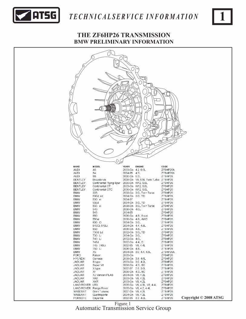
THE ZF6HP26 TRANSMISSIONBMW PRELIMINARY INFORMATION
Copyright © 2008 ATSG
Automatic Transmission Service Group
T E C H N I C A L S E R V I C E I N F O R M A T I O N 1
Figure 1

The ZF Company has produced several 6 speed transmissions which are being used in car lines such as Jaguar, BMW, Volkswagen and Audi.
Currently they have the 6HP19, the 6HP19FL and FLA, the 6HP26 and 6HP26A61, the 6HP32 and 32A. Although there are similarities among these units, they also have very significant differences. As a result, this short presentation will only be in regard to the 6HP26.
ZF6HP26 transmission within itself has several versions so as to accommodate the different car manufacturers and various engines they are fitted with, but the basic design and function of the transmission are the same.
The fundamental design that will be seen in all versions are as follows:
1. A torque converter with lockup clutch2. 3 driving clutches referred to as clutch A, B and E.3. 2 brake clutches referred to as clutch C and D.4. A Lepelletier Planetary Gear Train5. A Mechatronics Module
The differences that will be observed with regard to the various versions are as follows:
1. Power output and torque characteristics2. Torque converter configuration3. Clutches with different number of steel discs and lined plates4. Lepelletier planetary gear train with a different number of planet gears5. Valve body
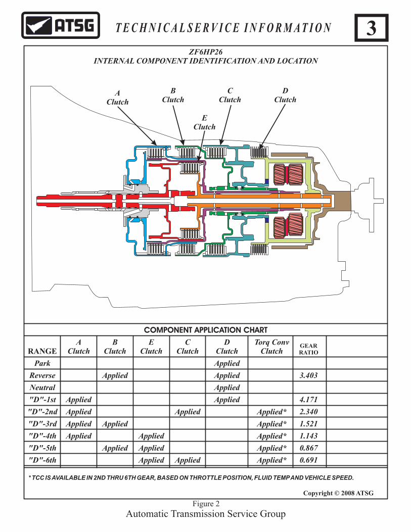
Mechanically, the six forward speeds and reverse are accomplished through the use of what is known as a Lepelletier planetary gear train, 3 driving clutches and 2 holding clutches as seen in the application chart displayed in Figure 2.
Electrically and hydraulically, this gear box is controlled by what is known as "The Mechatronic Module." This is a combination of a transmission control module and valve body configured as one unit. In other words, the computer for the transmission is mounted onto the valve body and is submerged in transmission fluid. As a result of this Mechatronic Module technology, the pass through case connector from the module to the vehicle harness will basically contain only power, ground and CAN Bus network wiring.
Another major deviation from the standard operational procedures we are familiar with in automatic transmissions is that with some models, there is not a mechanical connection from a selector lever to the manual valve. Instead, the driver makes a request of the desired gear engagement either through buttons or paddles or a shift lever, which then sends an electrical signal over the CAN bus network to the TCM. The TCM implements those commands taking into account various ambient conditions. This information is also used over the network so that the relevant gear positions are illuminated in the instrument cluster.
With the elimination of the conventional gear shift mechanism for a "shift by wire" strategy, there becomes a need for safety enhancements associated with this type system. One such example would be that when the ignition key is removed, it will automatically initiate a park engagement. Another is a hard wire serial data link from the various styles of selector lever input signals to the Mechatronic as a redundancy signal to the CAN bus input. Any errors will be reported and displayed either in the instrument cluster or via a scanner. And there will be the need for a mechanical emergency park release.
In addition to six forward speeds, there is a torque converter clutch strategy to further enhance fuel economy. Most of these converters use a two-friction surface lockup clutch design which is slip- controlled in all forward gears (1 through 6).
Automatic Transmission Service Group
T E C H N I C A L S E R V I C E I N F O R M A T I O N 2
Copyright © 2008 ATSG
THE ZF6HP26 TRANSMISSION
AClutch
BClutch
EClutch
CClutch
DClutch
Torq ConvClutchRANGE
GEARRATIO
4.171
3.403
2.340
1.521
1.143
0.867
0.691
COMPONENT APPLICATION CHART
Park
Reverse
Neutral
"D"-1st Applied
Applied Applied
Applied Applied*
Applied*
Applied*
Applied*
Applied*
Applied Applied
Applied
Applied
Applied
Applied
Applied
Applied
Applied Applied
Applied
Applied
"D"-2nd
"D"-3rd
"D"-4th
"D"-5th
"D"-6th
* TCC IS AVAILABLE IN 2ND THRU 6TH GEAR, BASED ON THROTTLE POSITION, FLUID TEMP AND VEHICLE SPEED.
ZF6HP26INTERNAL COMPONENT IDENTIFICATION AND LOCATION
AClutch
BClutch
DClutch
EClutch
CClutch
Automatic Transmission Service GroupFigure 2
3T E C H N I C A L S E R V I C E I N F O R M A T I O N
Copyright © 2008 ATSG
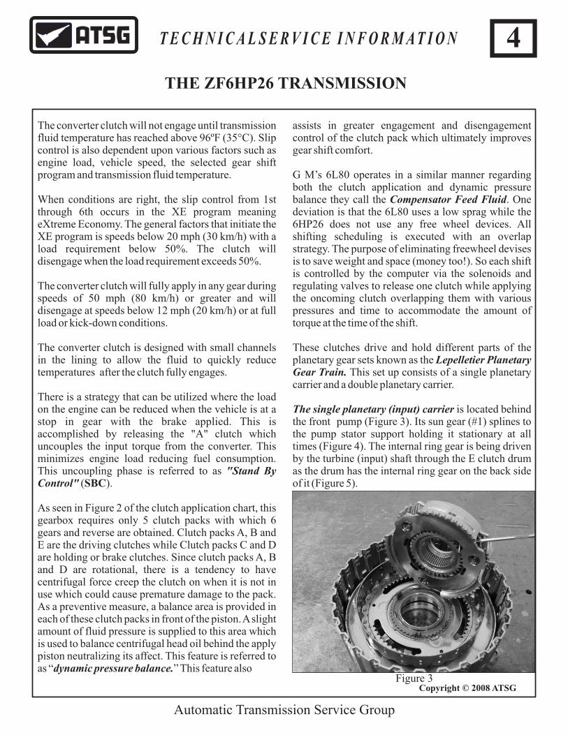
assists in greater engagement and disengagement control of the clutch pack which ultimately improves gear shift comfort.
G M’s 6L80 operates in a similar manner regarding both the clutch application and dynamic pressure balance they call the Compensator Feed Fluid. One deviation is that the 6L80 uses a low sprag while the 6HP26 does not use any free wheel devices. All shifting scheduling is executed with an overlap strategy. The purpose of eliminating freewheel devises is to save weight and space (money too!). So each shift is controlled by the computer via the solenoids and regulating valves to release one clutch while applying the oncoming clutch overlapping them with various pressures and time to accommodate the amount of torque at the time of the shift.
These clutches drive and hold different parts of the planetary gear sets known as the Lepelletier Planetary Gear Train. This set up consists of a single planetary carrier and a double planetary carrier.
The single planetary (input) carrier is located behind the front pump (Figure 3). Its sun gear (#1) splines to the pump stator support holding it stationary at all times (Figure 4). The internal ring gear is being driven by the turbine (input) shaft through the E clutch drum as the drum has the internal ring gear on the back side of it (Figure 5).
The converter clutch will not engage until transmission fluid temperature has reached above 96ºF (35°C). Slip control is also dependent upon various factors such as engine load, vehicle speed, the selected gear shift program and transmission fluid temperature.
When conditions are right, the slip control from 1st through 6th occurs in the XE program meaning eXtreme Economy. The general factors that initiate the XE program is speeds below 20 mph (30 km/h) with a load requirement below 50%. The clutch will disengage when the load requirement exceeds 50%.
The converter clutch will fully apply in any gear during speeds of 50 mph (80 km/h) or greater and will disengage at speeds below 12 mph (20 km/h) or at full load or kick-down conditions.
The converter clutch is designed with small channels in the lining to allow the fluid to quickly reduce temperatures after the clutch fully engages.
There is a strategy that can be utilized where the load on the engine can be reduced when the vehicle is at a stop in gear with the brake applied. This is accomplished by releasing the "A" clutch which uncouples the input torque from the converter. This minimizes engine load reducing fuel consumption. This uncoupling phase is referred to as "Control" ( ).
As seen in Figure 2 of the clutch application chart, this gearbox requires only 5 clutch packs with which 6 gears and reverse are obtained. Clutch packs A, B and E are the driving clutches while Clutch packs C and D are holding or brake clutches. Since clutch packs A, B and D are rotational, there is a tendency to have centrifugal force creep the clutch on when it is not in use which could cause premature damage to the pack. As a preventive measure, a balance area is provided in each of these clutch packs in front of the piston. A slight amount of fluid pressure is supplied to this area which is used to balance centrifugal head oil behind the apply piston neutralizing its affect. This feature is referred to as “dynamic pressure balance.” This feature also
Stand By SBC
Automatic Transmission Service Group
Figure 3
4T E C H N I C A L S E R V I C E I N F O R M A T I O N
Copyright © 2008 ATSG
THE ZF6HP26 TRANSMISSION

The carrier is then linked to the A clutch drum as seen in figure 3. So the front powerflow begins with the turbine shaft being driven by the converter which drives the internal ring gear that is integral to the turbine shaft. The internal ring gear then drives the pinions around the stationary sun gear causing the carrier to drive the A clutch drum in a reduction. When the A clutch applies, it will then drive a rear sun gear (#3) in the rear planetary in that reductive rotation. When the B clutch applies, it locks onto the A clutch drum which then drives a front (or middle #2 ) sun gear in the rear planetary in the same reductive speed.
The double planetary (output) carrier is located in the back of the transmission where its’ internal ring gear drives the output shaft (Figure 6). The rear sun gear (#3) in this double planetary assembly is driven by the A clutch and meshes with three short pinions. The front sun gear (#2) which meshes with three long pinions in this double planetary assembly is driven by the B clutch (Figure 7) while the C clutch is used to hold the # 2 sun gear stationary.
Automatic Transmission Service Group
Figure 4
Figure 5
The E clutch drum drives the carrier assembly (Figure 7) while the D clutch is used to hold it stationary.
Figure 6
Figure 7
1. A clutch drum hub drives rear sun gear.
1 23
3. E clutch drum hubdrives the rear planetary carrier.
2drives rear (or middle)sun gear.
. B clutch drum hub
5T E C H N I C A L S E R V I C E I N F O R M A T I O N
Copyright © 2008 ATSG
THE ZF6HP26 TRANSMISSION
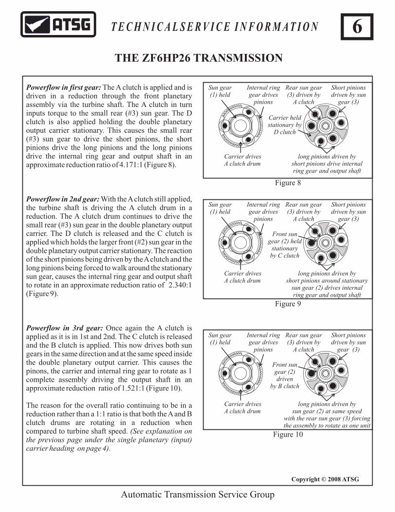
Powerflow in first gear: The A clutch is applied and is driven in a reduction through the front planetary assembly via the turbine shaft. The A clutch in turn inputs torque to the small rear (#3) sun gear. The D clutch is also applied holding the double planetary output carrier stationary. This causes the small rear (#3) sun gear to drive the short pinions, the short pinions drive the long pinions and the long pinions drive the internal ring gear and output shaft in an approximate reduction ratio of 4.171:1 (Figure 8).
Powerflow in 2nd gear: With the A clutch still applied, the turbine shaft is driving the A clutch drum in a reduction. The A clutch drum continues to drive the small rear (#3) sun gear in the double planetary output carrier. The D clutch is released and the C clutch is applied which holds the larger front (#2) sun gear in the double planetary output carrier stationary. The reaction of the short pinions being driven by the A clutch and the long pinions being forced to walk around the stationary sun gear, causes the internal ring gear and output shaft to rotate in an approximate reduction ratio of 2.340:1 (Figure 9).
Powerflow in 3rd gear: Once again the A clutch is applied as it is in 1st and 2nd. The C clutch is released and the B clutch is applied. This now drives both sun gears in the same direction and at the same speed inside the double planetary output carrier. This causes the pinons, the carrier and internal ring gear to rotate as 1 complete assembly driving the output shaft in an approximate reduction ratio of 1.521:1 (Figure 10).
The reason for the overall ratio continuing to be in a reduction rather than a 1:1 ratio is that both the A and B clutch drums are rotating in a reduction when compared to turbine shaft speed. (See explanation on the previous page under the single planetary (input) carrier heading on page 4).
Automatic Transmission Service Group
Sun gear (1) held
Internal ringgear drives
pinions
Carrier drivesA clutch drum
Short pinionsdriven by sun
gear (3)
Rear sun gear (3) driven by
A clutch
long pinions driven by short pinions drive internal ring gear and output shaft
Figure 8
Sun gear (1) held
Internal ringgear drives
pinions
Carrier drivesA clutch drum
Short pinionsdriven by sun
gear (3)
Rear sun gear (3) driven by
A clutch
long pinions driven by short pinions around stationary
sun gear (2) drives internal ring gear and output shaft
Figure 9
Carrier heldstationary by
D clutch
Front sungear (2) held
stationary by C clutch
Sun gear (1) held
Internal ringgear drives
pinions
Carrier drivesA clutch drum
Short pinionsdriven by sun
gear (3)
Rear sun gear (3) driven by
A clutch
long pinions driven by sun gear (2) at same speed
with the rear sun gear (3) forcing the assembly to rotate as one unit
Figure 10
Front sungear (2) driven
by B clutch
6T E C H N I C A L S E R V I C E I N F O R M A T I O N
Copyright © 2008 ATSG
THE ZF6HP26 TRANSMISSION

Powerflow in 4th gear: The A clutch still applied drives the small rear (#3) sun gear. The B clutch is released and the E clutch applies driving the double planetary output carrier at turbine shaft speed. The action of the carrier forcing the pinions to rotate around a reductive spinning sun gear causes the internal ring gear and output shaft to rotate in an approximate reduction ratio of 1.143:1 (Figure 11).
Powerflow in 5th gear: The A clutch is released and the B clutch is applied which drives the larger front (#2) sun gear in the double planetary output carrier. The E clutch is still applied driving the double planetary output carrier at turbine shaft speed. The reaction of the long pinions being forced to rotate around a reductive spinning sun gear (#2) causes the internal ring gear and output shaft to rotate in an approximate overdrive ratio of 0.867:1 (Figure 12).
Powerflow in 6th gear: The B clutch is released while the E clutch is still applied driving the double planetary output carrier at turbine shaft speed. The C clutch applies which now holds the larger (#2) sun gear in the double planetary output carrier. The reaction of the double planetary output carrier spinning at turbine shaft speed forcing the long pinions to rotate around a stationary larger (# 2) sun gear, causes the rear internal ring gear and output shaft to rotate in an approximate overdrive ratio of 0.691:1 (Figure 13).
Automatic Transmission Service Group
Sun gear (1) held
Internal ringgear drives
pinions
Carrier drivesA clutch drum
Short pinionsdriven by sun
gear (3)
Rear sun gear (3) driven by
A clutch
The carrier forces the pinionsto rotate around a reductive
turning rear sun gear (3) causing the ring gear and output shaft to
rotate just under a 1:1 ratio
Figure 11
Figure 12
Carrier drivenby E clutchat turbine
shaft speed
Figure 13
Front Planetary Assembly Inactive
(Freewheeling)
Front sun gear (2) driven by
B clutch
The carrier forces the pinionsto rotate around a reductive
turning front sun gear (2) causing an overdrive rotation of thering gear and output shaft
Carrier drivenby E clutchat turbine
shaft speed
Front Planetary Assembly Inactive
(Freewheeling)
Front sun gear (2)held stationary by
C clutch
The carrier forces the pinionsto rotate around a stationary
front sun gear (2) causing an overdrive rotation of thering gear and output shaft
Carrier drivenby E clutchat turbine
shaft speed
7T E C H N I C A L S E R V I C E I N F O R M A T I O N
Copyright © 2008 ATSG
THE ZF6HP26 TRANSMISSION
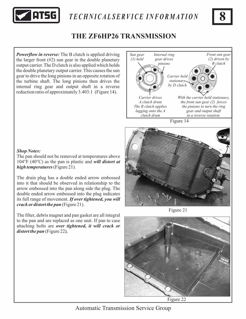
Powerflow in reverse: The B clutch is applied driving the larger front (#2) sun gear in the double planetary output carrier. The D clutch is also applied which holds the double planetary output carrier. This causes the sun gear to drive the long pinions in an opposite rotation of the turbine shaft. The long pinions then drives the internal ring gear and output shaft in a reverse reduction ratio of approximately 3.403:1 (Figure 14).
Automatic Transmission Service Group
Sun gear (1) held
Internal ringgear drives
pinions
Carrier drivesA clutch drum
The B clutch applieslugging onto the A
clutch drum
Front sun gear (2) driven by
B clutch
With the carrier held stationary,the front sun gear (2) forces the pinions to turn the ring
gear and output shaft in a reverse rotation.
Figure 14
Carrier heldstationary
by D clutch
8T E C H N I C A L S E R V I C E I N F O R M A T I O N
THE ZF6HP26 TRANSMISSION
Shop Notes:The pan should not be removed at temperatures above 104°F (40°C) as the pan is plastic and will distort at high temperatures (Figure 21).
The drain plug has a double ended arrow embossed into it that should be observed in relationship to the arrow embossed into the pan along side the plug. The double ended arrow embossed into the plug indicates its full range of movement. If over tightened, you will crack or distort the pan (Figure 21).
The filter, debris magnet and pan gasket are all integral to the pan and are replaced as one unit. If pan to case attaching bolts are over tightened, it will crack or distort the pan (Figure 22).
Figure 22
Figure 21

Whether you are working on an E-version or the M-version of the 6HP26, both contain the combination valve body and electronic control module called the Mechatronic Module located in the oil sump. The electronic module is completely sealed and oil tight designed to withstand temperatures up to 284ºF (140° C). It manages the complete electronic control of the transmission and is considered to be an integral part of the valve body making it not replaceable separately.
The electronic control module contains a Micro-Position Switch which monitors the position of the Park Cylinder with E-versions and the Manual Valve with M-versions. It also contains the Turbine and Output Speed Sensors, the Temperature Sensor and the Transmission Control Module (Figure 16).
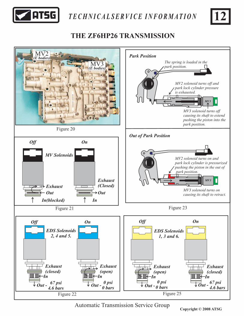
The valve body contains all the valves, springs, dampers and solenoids. The E-versions have 3 MV solenoids and 6 EDS or pressure control solenoids. The M-versions have the same 6 EDS solenoids but only 1 MV solenoid (Figure 17).
The MV 1 and 2 solenoids are identified by a black cap and contains an inlet, outlet and exhaust port. When the solenoid is energized, the inlet is open to the outlet port and the exhaust is blocked. When the solenoid turns off, the inlet is blocked and the outlet is opened to exhaust (Figure 21).
The MV3 solenoid is identified by a green cap and is part of the park lock cylinder.
The EDS or pressure control solenoids convert electrical current into a proportional hydraulic pressure. They are designed in two different ways:
EDS solenoids 1, 3 and 6 are identified by a yellow cap and are designed using a rising curve. In other words, at 0 mA it produces an output pressure of 0 psi (0 bars). At 700 mA output pressure rises as high as 67 psi (4.6 bar)s.
At 68ºF (20°C) they measure approximately 5 ohms. They are supplied with system voltage and are ground side controlled.
EDS solenoids 2, 4 and 5 are identified by a blue cap and are designed using a falling curve. In other words, at 0 mA it produces an output pressure of 67 psi (4.6 bars). At 700 mA output pressure rises as low as 0 psi (0 bars).
At 68ºF (20°C) they measure approximately 5 ohms. They are supplied with system voltage and are ground side controlled.
ISS
OSS
TCM
Park CylinderPosition SwitchTFT
Figure 16
Figure 17
EDS 6
MV1
EDS 4
EDS 5
EDS 3
EDS 2
EDS 1
9
Automatic Transmission Service Group
T E C H N I C A L S E R V I C E I N F O R M A T I O N
Copyright © 2008 ATSG
THE ZF6HP26 TRANSMISSION

10
Automatic Transmission Service Group
T E C H N I C A L S E R V I C E I N F O R M A T I O N
Copyright © 2008 ATSG
THE ZF6HP26 TRANSMISSION
CASE CONNECTOR TERMINAL FUNCTION
12
34
56
7
89
10
1112
1314
1516
PIN # FUNCTION NOTES
1
2
3
4
5
6
7
8
9
10
11
12
13
14
15
16
“M” SHIFT
“M” GATE POSITION
TCM TERMINAL31-1
CAN L
ISO K
TOUCH -
TOUCH +
CAN H
SHIFTLOCK
NOT IN USE
TCM TERMINAL 15
“P” SIGNAL
SHIFTLOCK
NOT IN USE
TCM TERMINAL 30
INTERLOCK
TCM TERMINAL31-2
MANUAL SHIFT PROGRAM
CONTROL SIGNAL FOR SHIFTLOCK & INTERLOCK
PERMANENT POSITIVE (EGS SUPPLY VOLTAGE)
CAN LOW
K LINE
MANUAL DOWNSHIFT SIGNAL
MANUAL UPSHIFT SIGNAL
CAN HIGH
WAKE-UP SIGNAL
P LINE FOR STARTER INHIBIT
APPLY BRAKE BEFORE SELECTING POSITION
GROUND
GROUND
Figure 18

11
Automatic Transmission Service Group
T E C H N I C A L S E R V I C E I N F O R M A T I O N
Copyright © 2008 ATSG
THE ZF6HP26 TRANSMISSION
CASE CONNECTOR TERMINAL FUNCTION
12
34
56
7
89
10
1112
1314
1516
PIN # FUNCTION NOTES
1
2
3
4
5
6
7
8
9
10
11
12
13
14
15
16
“E” SHIFT
SERIES LINE
TCM TERMINAL31-1
CAN L
ISO K
NOT IN USE
NOT IN USE
CAN H
NOT IN USE
NOT IN USE
TCM TERMINAL 15
“P” SIGNAL
NOT IN USE
NOT IN USE
TCM TERMINAL 30
NOT IN USE
TCM TERMINAL31-2
AVAILABILITY LINE FROM STEERING COLUMN SWITCH CENTER
PERMANENT POSITIVE (EGS SUPPLY VOLTAGE)
CAN LOW
K LINE
CAN HIGH
WAKE-UP SIGNAL
P LINE FOR STARTER INHIBIT
GROUND
GROUND
Figure 19
MV3
Out of Park Position
MV2 solenoid turns on andpark lock cylinder is pressurizedpushing the piston in the out of park position.
MV3 solenoid turns on causing its shaft to retract.
MV3
Park Position
MV2 solenoid turns off andpark lock cylinder pressure is exhausted.
MV3 solenoid turns off causing its shaft to extendpushing the piston into thepark position.
The spring is loaded in the park position.
In(blocked)
Out
Exhaust
In
Out
Off On
Out -
Exhaust(open)
In
Off
Out - 67 psi4.6 bars
In
OnOff On
Figure 21
Figure 25Figure 22
Exhaust(Closed)
Exhaust(closed)
Out -
Exhaust(open)
In
Out -
In
Exhaust(closed)
MV Solenoids
EDS Solenoids1, 3 and 6.
EDS Solenoids2, 4 and 5.
Automatic Transmission Service Group
12T E C H N I C A L S E R V I C E I N F O R M A T I O N
Copyright © 2008 ATSG
THE ZF6HP26 TRANSMISSION
Figure 20
MV3(E bodies)
MV2(E bodies)
Figure 23
0 psi0 bars
0 psi0 bars
67 psi4.6 bars
Automatic Transmission Service Group
13T E C H N I C A L S E R V I C E I N F O R M A T I O N
Copyright © 2008 ATSG
THE ZF6HP26 TRANSMISSION
Automatic Transmission Service Group
T E C H N I C A L S E R V I C E I N F O R M A T I O N
Copyright © 2008 ATSG
THE ZF6HP26 TRANSMISSION
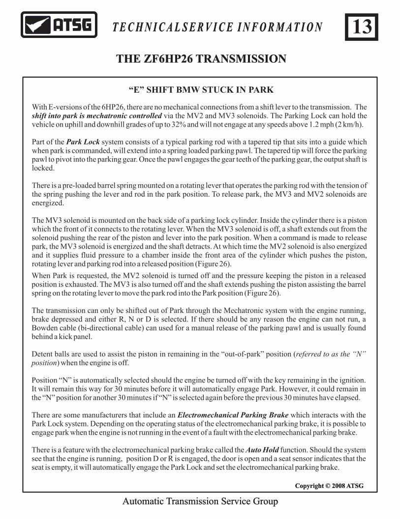
With E-versions of the 6HP26, there are no mechanical connections from a shift lever to the transmission. The shift into park is mechatronic controlled via the MV2 and MV3 solenoids. The Parking Lock can hold the vehicle on uphill and downhill grades of up to 32% and will not engage at any speeds above 1.2 mph (2 km/h).
Part of the Park Lock system consists of a typical parking rod with a tapered tip that sits into a guide which when park is commanded, will extend into a spring loaded parking pawl. The tapered tip will force the parking pawl to pivot into the parking gear. Once the pawl engages the gear teeth of the parking gear, the output shaft is locked.
There is a pre-loaded barrel spring mounted on a rotating lever that operates the parking rod with the tension of the spring pushing the lever and rod in the park position. To release park, the MV3 and MV2 solenoids are energized.
The MV3 solenoid is mounted on the back side of a parking lock cylinder. Inside the cylinder there is a piston which the front of it connects to the rotating lever. When the MV3 solenoid is off, a shaft extends out from the solenoid pushing the rear of the piston and lever into the park position. When a command is made to release park, the MV3 solenoid is energized and the shaft detracts. At which time the MV2 solenoid is also energized and it supplies fluid pressure to a chamber inside the front area of the cylinder which pushes the piston, rotating lever and parking rod into a released position (Figure 26).
“E” SHIFT BMW STUCK IN PARK
When Park is requested, the MV2 solenoid is turned off and the pressure keeping the piston in a released position is exhausted. The MV3 is also turned off and the shaft extends pushing the piston assisting the barrel spring on the rotating lever to move the park rod into the Park position (Figure 26).
The transmission can only be shifted out of Park through the Mechatronic system with the engine running, brake depressed and either R, N or D is selected. If there should be any reason the engine can not run, a Bowden cable (bi-directional cable) can used for a manual release of the parking pawl and is usually found behind a kick panel.
Detent balls are used to assist the piston in remaining in the “out-of-park” position (referred to as the “N” position) when the engine is off.
Position “N” is automatically selected should the engine be turned off with the key remaining in the ignition. It will remain this way for 30 minutes before it will automatically engage Park. However, it could remain in the “N” position for another 30 minutes if “N” is selected again before the previous 30 minutes have elapsed.
There are some manufacturers that include an Electromechanical Parking Brake which interacts with the Park Lock system. Depending on the operating status of the electromechanical parking brake, it is possible to engage park when the engine is not running in the event of a fault with the electromechanical parking brake.
There is a feature with the electromechanical parking brake called the Auto Hold function. Should the system see that the engine is running, position D or R is engaged, the door is open and a seat sensor indicates that the seat is empty, it will automatically engage the Park Lock and set the electromechanical parking brake.

Automatic Transmission Service Group
14T E C H N I C A L S E R V I C E I N F O R M A T I O N
Copyright © 2008 ATSG
THE ZF6HP26 TRANSMISSION
Automatic Transmission Service Group
T E C H N I C A L S E R V I C E I N F O R M A T I O N
Copyright © 2008 ATSG
THE ZF6HP26 TRANSMISSION
“E” SHIFT BMW STUCK IN PARK....continued
Another aspect of this electromechanical parking brake is if it can not switch from the “hold” to “lock” mode, the Park Lock is automatically engaged following a plausibility check in the EGS control unit. The plausibility check determines whether position N is engaged, the speed is zero and the engine and ignition are off.
As mentioned previously, a Bowen cable is used as a mechanical emergency release of the parking lock system should it not be able to release automatically. This could be caused by several reasons such as a battery failure, the engine can not start, a problem with the engine’s electrical system or the transmission’s electrical system to name a few.
It is imperative that this emergency release be used when towing. Depending on the type of fault present, the “N” hold function can not be guaranteed during the entire time of the tow even if output speed is recognized (Please refer to owners manual for the vehicle being towed).
In some applications, this Bowden cable is only accessible by unlocking a cover with the vehicle key.
Whenever the emergency cable is used to release Park, a message of some form will be displayed in the instrument cluster indicating so.
For M-versions of the 6HP26, there is a mechanical connection from a shift lever to a manual valve with which P, R, N and D can be selected. As a result, MV2 and MV3 solenoids are eliminated.
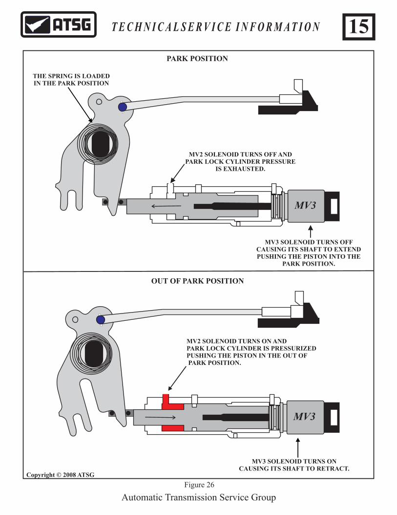
MV2 SOLENOID TURNS ON ANDPARK LOCK CYLINDER IS PRESSURIZEDPUSHING THE PISTON IN THE OUT OF PARK POSITION.
MV3
PARK POSITION
OUT OF PARK POSITION
MV3
MV3 SOLENOID TURNS ON CAUSING ITS SHAFT TO RETRACT.
Figure 26
THE SPRING IS LOADED IN THE PARK POSITION
MV3 SOLENOID TURNS OFF CAUSING ITS SHAFT TO EXTENDPUSHING THE PISTON INTO THE
PARK POSITION.
MV2 SOLENOID TURNS OFF ANDPARK LOCK CYLINDER PRESSURE
IS EXHAUSTED.
Automatic Transmission Service Group
15T E C H N I C A L S E R V I C E I N F O R M A T I O N
Copyright © 2008 ATSG

MV3 MV2
PARK ACTUATORROD
Figure 27
EDS 6
MV 1
EDS 4
EDS 5
EDS 3
EDS 2
EDS 1
EDS 2
Automatic Transmission Service Group
16T E C H N I C A L S E R V I C E I N F O R M A T I O N
Copyright © 2008 ATSG

Automatic Transmission Service Group
Electronic Transmission Control
As previously stated, there is no mechanical connection from the gear shift lever to the transmission with E-version units. The positions selected by the shift lever are sent over the CAN bus network to the Mechatronic Module and is known as shift by wire.
Shift by Wire StylesOne example of a shift lever used for shift by wire has some features that resembles a typical shift lever (Figure 28). What will catch your attention quickly is that from top to bottom the lever will begin with the reverse position symbolized by an upper case R.
P for Park is located at the mid-position while D for Drive follows underneath.
Along side the R is a corresponding Up arrow, along side the P is an Up and Down arrow while along side the D is a Down arrow.
Position R: To select reverse the brake needs to be depressed and the selector lever be pushed to its fullest travel in the up or counter clockwise direction.
Position N: If a neutral position is desired while in Reverse, a simple downward tap of the shift lever is all that is needed. Likewise from the Drive position, a simple upward tap is all that is required. From the Park position, a tap of the lever in either direction will place the vehicle in Neutral. Neutral will automatically be selected when the ignition is turned off but the key remains in the cylinder. Park will automatically be selected after 30 minutes unless N is selected before the 30 minutes have elapsed at which time an additional 30 minutes is added to the time in Neutral.
Position D: Depress the brake and pull the selector lever to its fullest travel in the downward or clockwise direction.
Position P: Park engages by a push of a button built into the shift lever. Park automatically disengage when R, N or D is selected when the engine is running. Park will automatically engage when the ignition key is removed from the cylinder.
RND
P
Figure 28
RN PD
0
20
40
6080 00
200220
240
260 0
1
2 5
6
7
D
L4
RN PD
RN PD
RN PD
RN PD
Park Display Neutral Display
Reverse DisplayDrive Display
L Program(1 through 6)
Figure 30
17T E C H N I C A L S E R V I C E I N F O R M A T I O N
Copyright © 2008 ATSG
THE ZF6HP26 TRANSMISSION
1
2
34 5
6
7
8
90120
210
300
0
20
40
6080
100120
140
160
200
0
20
40
60
80100
120 150180
210
240
270
300
330180
mph
0 11/2
1/min x 1000
M
ON
B
w
w
Figure 29
Copyright © 2008 ATSG

ZF 0501 212931
2-4737-000
DAMAGED BRIDGE SEAL
Figure 31
ENOUGH LINE PRESSURE IS LOSTFROM THE DAMAGED BRIDGE SEAL
TO CAUSE THE TCM TO PUT THETRANSMISSION BACK INTO PARK
BRIDGE SEAL
Automatic Transmission Service Group
18T E C H N I C A L S E R V I C E I N F O R M A T I O N
Copyright © 2008 ATSG
ZF Part Number0501215718

Another feature that could be encountered is referred to the L Push Button in MFL (Figure 32). This as a multi-function push button switch with a limiting function strategy. When D is selected, the transmission will automatically shift through all 6 speeds utilizing a variety of shift profiles programmed into the computer to accommodate the operator’s driving habits.
In the limitation mode there are no manual up shift controls nor is there a forced up-shift at maximum engine rpm. The computer will also not allow certain downshift requests that would cause damage to the transmission and/or engine.
(Most Jaguar models utilize the Mechanical Mechatronics in conjunction with a J Gate shifter).
Indication Details:
In addition to the limitation mode lights being illuminated in the instrument cluster, Park, Reverse, Neutral and Drive selections are also displayed.
Similar to the previous style shift lever option, R, N and D positions are associated with up and down arrows. When reverse is selected the R will illuminate as is with P for Park, N for Neutral and D for Drive. The L1 through L6 will illuminate below the D light in a separate window.
When the vehicle is running in Park for a period of time, all gear position indicator lights will go off.
This will occur when the CAN bus enters the sleep mode. If the CAN bus is wakened by a signal other than a gear selection, the lights may remain in the off state.
As previously mentioned, the vehicle will hold a neutral position for 30 minutes when the engine is off and the key remains in the cylinder, after which it will automatically go to the Park position. The N light will begin to flash at a 1.5 Hz frequency prior to 30 minute expiration time.
L
Figure 32
Whenever the limitation mode is selected by pressing the L button, the current gear at that time is retained and an indicator light is illuminated identifying the selected gear (Figure 32). If the vehicle was in 4th gear at the time L was selected, the highest gear will be 4th. Gears 1 through 4 will then be shifted automatically.
The transmission will downshift 1 gear at a time each time the L button is pressed. That gear will then be maintained as the most upper gear it will shift up to automatically. And as previously stated the highest gear selected in the limitation mode will be illuminated in the instrument cluster (L1 through L6) as illustrated in figure 32.
19
Automatic Transmission Service Group
T E C H N I C A L S E R V I C E I N F O R M A T I O N
Copyright © 2008 ATSG
THE ZF6HP26 TRANSMISSION
Automatic Transmission Service Group
T E C H N I C A L S E R V I C E I N F O R M A T I O N 20
Copyright © 2008 ATSG
THE ZF6HP26 TRANSMISSION
DTC
!
SPORT
PR
ND
M S
+
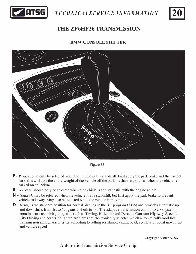
BMW CONSOLE SHIFTER
Figure 33
P - Park, should only be selected when the vehicle is at a standstill. First apply the park brake and then select park, this will take the entire weight of the vehicle off the park mechanism, such as when the vehicle is parked on an incline.
R - Reverse, should only be selected when the vehicle is at a standstill with the engine at idle.
N - Neutral, may be selected when the vehicle is at a standstill, but first apply the park brake to prevent vehicle roll away. May also be selected while the vehicle is moving.
D - Drive, is the standard position for normal driving in the XE program (AGS) and provides automatic up and downshifts from 1st to 6th gears and 6th to 1st. The adaptive transmission control (AGS) system contains various driving programs such as Towing, Hillclimb and Descent, Constant Highway Speeds, City Driving and cornering. These programs are electronically selected which automatically modifies transmission shift characteristics according to rolling resistance, engine load, accelerator pedal movement and vehicle speed.

Automatic Transmission Service Group
T E C H N I C A L S E R V I C E I N F O R M A T I O N 21
Copyright © 2008 ATSG
THE ZF6HP26 TRANSMISSION
“S” ProgramThe “S” Program is a performance oriented program, where the gear changing characteristics of the transmission are moved up to higher engine speeds. To select the “S” Program, push the button located on the console that says “SPORT” as seen in Figure ??. Gears 1-6 and 6-1 are selected automatically.
“M” ProgramThe “M” program is a manual shift program which is activated by simply pushing the selector lever to the left and then to the plus sign for upshifting or the minus sign for downshifting. It is possible to drive off in first, second or third gears, however fourth gear can be manually selected from a speed of 6 mph (10 km/h). Fifth gear can be selected manually from a speed of 22 mph (35 km/h and sixth gear can be selected manually from a speed of 28 mph (45 km/h).
Failsafe OperationWhen a fault occurs all solenoids turn off. The hydraulic system is designed so that restricted operation is still possible. This means that if the transmission is in 1st, 2nd or 3rd at the time of the fault, when all solenoids turn off, the hydraulic design is to force a 3rd gear hold. Likewise, if the transmission is in 4th, 5th or 6th when the fault occurs, when all solenoids turn off, the hydraulic design is to force a 5th gear hold.
The vehicle will then move forward under these restrictions. Once the engine is turned off and restarted, it will not be possible to select D. The vehicle will remain in the Park position.
If the fault should occur while in the reverse range, neutral will be selected and when the vehicle drops below 3 mph (5 km/h), Park will engage.
Under these conditions the only way park can be released is with the emergency mechanical release cable.
Shift lever operation can not be detected or implemented if total transmission control failure should occur or failure with the Steering Column Switch Center (SZL) has occurred. In addition to flashing warning lights, a notable acoustic warning “gong” type sound will occur notifying the driver that a problem exists. A decrease in acceleration will then follow these warning signals.
The EGS has the capability to output various text messages in a “Check Control Message” display in the instrument cluster.
Should there be CAN bus failure the transmission will shift to 3rd or 5th depending upon vehicle speed and the previous gear engaged at the time of fault. After a restart, 3rd gear is engaged in the D position. All gear select ranges will occur from the hard wire input. The shift lock function is deactivated making it possible to select a gear without depressing the brake. The N hold feature turns off and Park will engage below 1.2 MPH (2 km/h) automatically.
BMW CONSOLE SHIFTER
Automatic Transmission Service Group
T E C H N I C A L S E R V I C E I N F O R M A T I O N 22
Copyright © 2008 ATSG
THE ZF6HP26 TRANSMISSION
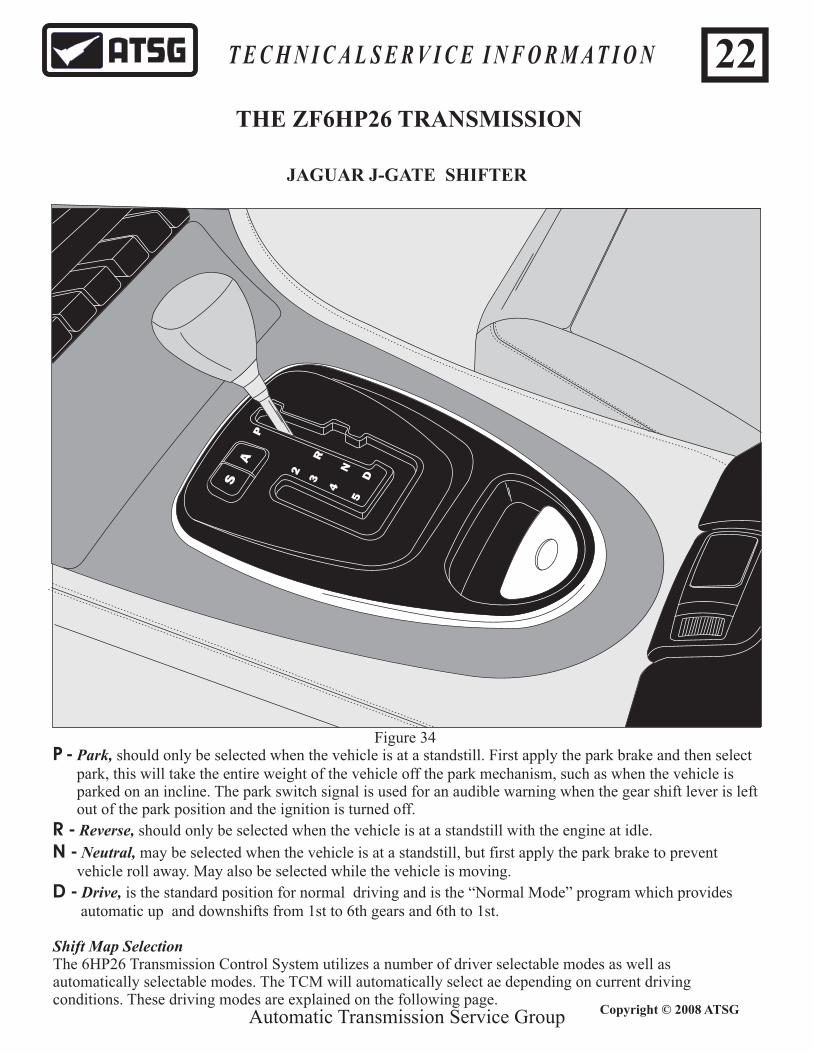
JAGUAR J-GATE SHIFTER
P
R
N
D2
3
4
5
SA
P - Park, should only be selected when the vehicle is at a standstill. First apply the park brake and then select park, this will take the entire weight of the vehicle off the park mechanism, such as when the vehicle is parked on an incline. The park switch signal is used for an audible warning when the gear shift lever is left out of the park position and the ignition is turned off.
R - Reverse, should only be selected when the vehicle is at a standstill with the engine at idle.
N - Neutral, may be selected when the vehicle is at a standstill, but first apply the park brake to prevent vehicle roll away. May also be selected while the vehicle is moving.
D - Drive, is the standard position for normal driving and is the “Normal Mode” program which provides automatic up and downshifts from 1st to 6th gears and 6th to 1st.
Shift Map SelectionThe 6HP26 Transmission Control System utilizes a number of driver selectable modes as well as automatically selectable modes. The TCM will automatically select ae depending on current driving conditions. These driving modes are explained on the following page.
Figure 34

Automatic Transmission Service Group
T E C H N I C A L S E R V I C E I N F O R M A T I O N 23
Copyright © 2008 ATSG
THE ZF6HP26 TRANSMISSION
JAGUAR J-GATE SHIFTER
Manual ModeWhen the driver moves the shift lever to the left in the J-Gate, second, third, fourth or fifth gears can be selected. When the shifter is moved from the “D” position to position 5 in manual mode, selector position in transmitted to the TCM via CAN by hall effect switches in the J-Gate assembly.
Sport Mode“Sport Mode” is a driver selected program which can be activated by pressing the “S” button on the console. Sport mode raises the transmission shift points as well as operating pressure.
Cruise ModeWhen the driver engages cruise control the TCM will select a new shift map to reduce shift busyness during cruise mode.
Hot Mode“Hot Mode” is an adaptive mode the transmission will enter when atf, engine coolant, engine oil temperature or substrate (TCM) temperature becomes too high. This mode will automatically select new shift and TCC apply maps in an attempt to reduce the temperature.The shift map for “Hot Mode” will enable the transmission to shift to higher gears at lower speeds and apply TCC at lower vehicle speeds in lower gears.
Traction Control Mode“Traction Control Mode” is an adaptive program which automatically engages when wheel slippage is detected. The TCM will react by allowing the transmission to upshift thereby lowering the torque applied the the wheels in an effort to reduce wheel spin and will also engage the ABS system.
Hill & Trailer Towing Mode“Hill & Trailer Mode” is an adaptive program, when the TCM detects reduced acceleration for a certain percentage of throttle opening, hill and trailer mode is automatically engaged by the TCM. When this program is engaged, a new shift and TCC apply map will be selected by the TCM. This is designed to reduce shift hunting when climbing a steep incline under load. The transmission will stay in a particular gear longer under these conditions.

Automatic Transmission Service Group
Fault Indications:
1. If for any reason CAN bus signals become invalid, the shift pattern and P position indicator lights will remain illuminated regardless of gear selection.
2. When the ignition switch is cycled to the ON position and position P is not detected, position N will begin to flash in addition to the illumination of the “emergency release may be operated” message.
3. While in the D range, should the transmission develop a mechanical problem, the R and N indicator lights illuminate while all the arrows and the D indicator light flash at a frequency of 1.5 Hz. When P is selected under the same conditions, the P, R, N and D positions remain lite while the arrows continue to flash.
4. If the transmission is develops a problem and the CAN bus communication is not functional, the instrument cluster assumes control flashing the arrows at a 1.5Hz frequency while illuminating the R, N and D positions. P will be off.
Interlock
The “ignition key inserted or not inserted” are monitored by the CAS module which signals ths status to the transmission control module (EGS). When it sends the “ignition key not inserted” signal to the EGS the Park Lock is engaged. The Park Lock can only be released when the ignition key is inserted and the engine is running.
Starter Interlock
This same CAS module is used to allow start up by monitoring signals from the EGS; the gear selection over the CAN bus and the P signal over a hard wire input directly from the P position sensor. When a P or N selection has been verified, start up is then permitted. The hard wire P input allows for start up in P should the CAN bus be down.
If the emergency release is operated, the vehicle will not start.
Warm-up Program
When engine temperature is below 60
60
°C, a warm-up strategy is immediately selected causing up-shifts to occur at a higher engine RPM. This strategy allows for the engine and the catalytic converter to reach operating temperature quicker. The strategy is aborted after 120 seconds or the engine temperature has risen above 140ºF ( °C), which ever occurs first.
Reverse Interlock
If 5 km/h or higher speeds are observed when reverse is selected, the computer will place the transmission neutral illuminating the N indicator lamp. When speed drops below 3 mph (5 km/h) will a reverse engagement be allowed.
Adaptive Transmission Control
When in the D range, the computer automatically shifts the transmission through all 6 speeds and converter clutch apply adjusting both the shift points and shift feel providing the driver with most comfortable gear shift characteristics possible. It can on the fly, depending upon the speed in which the accelerator pedal is depressed, switch from an extreme economy shift profile to a performance-oriented shift profile.
Curve recognition
Curve recignition is another type of shift control strategy preventing up-shifts or downshift while in turns. The DSC module detects variations in front and rear wheel speeds as well as yaw rate signals, steering wheel angle signals and vehicle speed to further determine cornering forces. Once signals indicate straight ahead driving, up-shifts and downshift strategies resume.
24T E C H N I C A L S E R V I C E I N F O R M A T I O N
Copyright © 2008 ATSG
THE ZF6HP26 TRANSMISSION

Automatic Transmission Service Group
Tire Size
It is important to note that tire size plays an important role in proper curve recognition strategy. For example, ATSG had experienced a call where a persons BMW had 4 very worn tires. One of the tires went flat and was temporarily replaced with the spare. The spare had a much taller tread profile in comparison to the other three tires. As a result, the computer saw a variation in wheel speed and interpreted it as being in a slight turn. The faster the accelerator was depressed, the less it would up-shift. At lighter throttle openings a loss of higher gears was noticed. Kick-down shifts were also prohibited. A capable scan tool provided curve recognition data parameters and it was observed that while driving straight the parameter read “activated” causing the various forward driving shift complaints.
Brake evaluation is another shift strategy where the computer monitors wheel speed and the degree in which the brake pedal is depressed. From these inputs as well as what gear the transmission was in when braking began will the computer determine the optimum downshift profile.
There is a constant driving evaluation program that observes freeway driving taking note that a constant accelerator pedal position and vehicle speed is maintained. As a result, kick-down shifts become more responsive. Should the driver decide to enter a passing situation, when requested, a downshift will occur immediately. The winter program is activated when wheel slip is observed causing the transmission to have 2nd gear starts and lower shift points. All downshift request that would cause the wheels to spin will also be suppressed.
The hill recognition function provides raised shift points when it detects slow vehicle speed and high engine load during a climb. High altitude adaptations also take place to compensate for performance reduction.
The cruise control shift strategy obviously maintains the speed requested by the driver. The strategy is such to prevent shift business as well as converter clutch cycling without compromising on the required shifts while ensuring driving comfort.
Besides different shift profiles, shift adapt control maintains shift quality over the lifetime of the transmission. By monitoring engine torque, turbine and output speed, the EGS calculates slip time and slip ratio. It then makes necessary adjustments by operating the EDS solenoids to control clutch pressure optimizing shift quality and increasing the life span of the friction plates.
It is imperative that after repairs the shift adapts are reset using a capable scan tool (factory uses a new and improved version of the GT1 which is a computer based diagnostics called DISplus).
There are several strategies used for Emergency Programs depending on the type of failure. There could be electrical failures, CAN bus communication failures and mechanical failures.
The use of the Mechatronic Assembly and redundant selector lever inputs (CAN bus and hard wire) aid in reducing the possible faults. Multiple substitute programs are used when a fault does occur in an attempt to prevent further damage to the transmission such as restricted gear selection, restricted shifting and deactivation of all solenoids.
25T E C H N I C A L S E R V I C E I N F O R M A T I O N
Copyright © 2008 ATSG
THE ZF6HP26 TRANSMISSION

Automatic Transmission Service Group
26T E C H N I C A L S E R V I C E I N F O R M A T I O N
Figure 35 Figure 36
The Valve BodyWhen removing the valve body, BMW says to remove only the green colored bolts. If you are working with a Jaguar unit, the bolts may not be color coded. In these cases you may notice the use of both round and square top bolt heads. Only the square top bolts should be removed to release the valve body assembly from the case (Figure 35). When splitting the valve body, use the slot shown in Figure 36 to lift the spacer plate and lower valve body off of the upper valve body. The upper valve body (channel plate) contains all the check balls, check valves, damper pistons and screens.
The Valve Body Separator PlatesReferred to as Intermediate Plates have a coating that is damaged during valve body dis-assembly and should be replaced. Available through ZF for the 6HP19, 26 & 32 according to transmission tag and valve body code.Part: # 1068 227 035 01 #1068 227 047 01 #1068 227 051 01 #1068 227 052 01 #1068 227 053 01
Copyright © 2008 ATSG
THE ZF6HP26 TRANSMISSION

Manual Valve (M Shift) - Used for manual gear selection for Park, Neutral, Forward and Reverse.
Lubricating Valve - Reduces and guarantees the pressure needed for lubrication. It also imposes an upper limit on the pressure.
Converter Pressure Valve - Reduces system pressure and guarantees the pressure needed for the converter. It also limits maximum converter pressure to prevent the converter from expanding. If EDS 6 is actuated, the oil passage behind the converter lock-up piston is vented.
Main Pressure Regulator Valve - Regulates the oil pressure built up by the primary pump, excess oil is returned to the pump intake port.
Converter Lock-up Clutch Valve - Is controlled jointly with the converter pressure valve by the EDS 6 Solenoid. When the solenoid operates, the direction of flow is reversed. As the converter pressure valve vents the piston chamber behind the lock-up clutch piston, the area in front of the lock-up clutch plate is charged.
Retaining Valve/Clutch “E”, “B”, “A” & “D” - Retaining Valves “E”, “B”, “A” and “D” prevents the regulating function of clutch valves “E”, “B”, “A” and “D” during the shift at the appropriate time, so clutch pressure rises to system pressure. Both the retaining valves and the clutch valves are regulated by the corresponding EDS solenoids.
Clutch Valves “E”, “B”, “A”, “C”, “D1” & “D2” - The Clutch Valves are a variable pressure reducing valve. It is controlled by the relevant EDS Solenoid which determines clutch pressure during the shift.
Shift Valve 2 - Shift Valve 2 is actuated by solenoid valve 2 and supplies system pressure to operate the relevant clutches.
Shift Valve 1 - Shift Valve 1 keeps the gear actually selected in use if the power should fail while driving. If the car is restarted and the EGS is in the emergency program, a predetermined gear is selected.
Pressure Reducing Valve - The Pressure Reducing Valve lowers system pressure to approximately 73 PSI (5 Bar), which is then applied to the downstream pressure control circuits (EDS 1-6) and solenoid valves (MV1-2). The pressure control circuits and solenoid valves need a constant feed pressure if the are to function properly.
Position Valve “D” (E Shift Only) - The Position Valve takes the place of the manual valve and diverts system pressure to regulate the individual friction elements.
Park Lock Cylinder (E Shift Only) - The park lock is engaged electrically by the park lock cylinder.
Parking Lock Valve (E Shift Only) - The Parking Lock Valve is ti shift the park lock cylinder to the neutral or park positions. The parking lock valve is actuated by MV2. MV2 Active = Neutral Position MV2 Inactive = Park Position
Automatic Transmission Service Group
27T E C H N I C A L S E R V I C E I N F O R M A T I O N
Copyright © 2008 ATSG
THE ZF6HP26 TRANSMISSION
DESCRIPTION OF VALVES

1. MV1 Solenoid Damper2. Shift Valve 23. Shift Valve 14. Holding Valve D1
3 4
5
6 7
EDS6
EDS4
EDS5
EDS3
EDS2
EDS1
MV1
Automatic Transmission Service Group
28
5. Solenoid Feed Limit Valve6. Holding Valve B7. Holding Valve A* Shaded area in the valve body indicate retainer location
ZF6HP26 M-SHIFT LOWER VALVE BODY
Figure 37
T E C H N I C A L S E R V I C E I N F O R M A T I O N
Copyright © 2008 ATSG
1
2

Automatic Transmission Service Group
29
5. Pressure Regulator Valve6. TCC Switch Valve7. Lubrication/Cooler Valve8. Manual Valve* Shaded area in the valve body indicate retainer location
1. Clutch Valve A2. Clutch Valve E3. Holding Valve E4. TCC Regulator Valve
1 2
3
4
5
6
7
8
ZF6HP26 M-SHIFT LOWER VALVE BODY
Figure 38
T E C H N I C A L S E R V I C E I N F O R M A T I O N
Copyright © 2008 ATSG
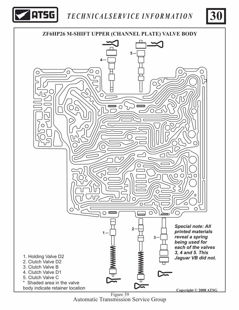
1. Holding Valve D2 2. Clutch Valve D23. Clutch Valve B4. Clutch Valve D15. Clutch Valve C* Shaded area in the valve body indicate retainer location
1
4
5
2
3
Automatic Transmission Service Group
30
ZF6HP26 M-SHIFT UPPER (CHANNEL PLATE) VALVE BODY
Special note: Allprinted materialsreveal a spring being used foreach of the valves 3, 4 and 5. This Jaguar VB did not.
Figure 39
T E C H N I C A L S E R V I C E I N F O R M A T I O N
Copyright © 2008 ATSG

32 4
5
6 7
EDS6
EDS4
EDS5
EDS3
EDS2
EDS1
MV1
Automatic Transmission Service Group
31
5. Pressure Reducing Valve6. Holding Valve B7. Holding Valve A* Shaded area in the valve body indicate retainer location
ZF6HP26 E-SHIFT LOWER VALVE BODY
Figure 40
T E C H N I C A L S E R V I C E I N F O R M A T I O N
Copyright © 2008 ATSG
MV3
1
1. MV3 Solenoid Valve/Park Lock Cylinder2. Shift Valve 23. Shift Valve 14. Holding Valve D1
1 2
3
4
5
6
7 8
MV2
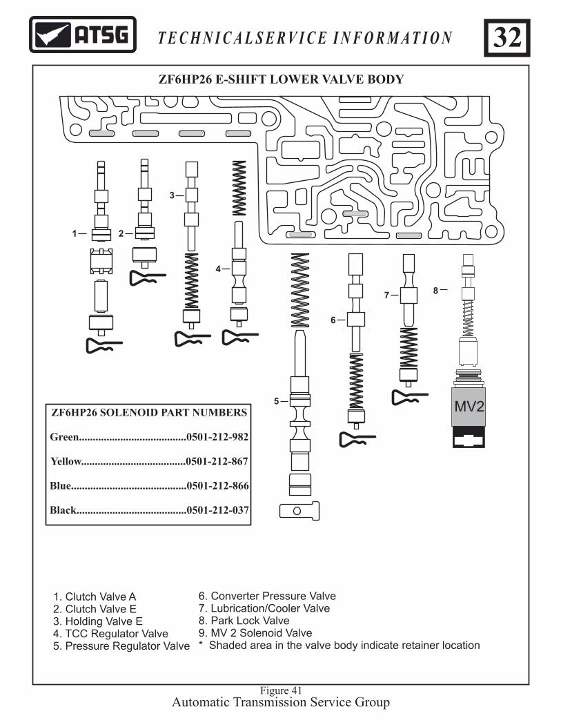
ZF6HP26 E-SHIFT LOWER VALVE BODY
Automatic Transmission Service Group
T E C H N I C A L S E R V I C E I N F O R M A T I O N
Figure 41
6. Converter Pressure Valve7. Lubrication/Cooler Valve8. Park Lock Valve9. MV 2 Solenoid Valve* Shaded area in the valve body indicate retainer location
1. Clutch Valve A2. Clutch Valve E3. Holding Valve E4. TCC Regulator Valve5. Pressure Regulator Valve
32
ZF6HP26 SOLENOID PART NUMBERS
Green.......................................0501-212-982
Yellow......................................0501-212-867
Blue..........................................0501-212-866
Black........................................0501-212-037
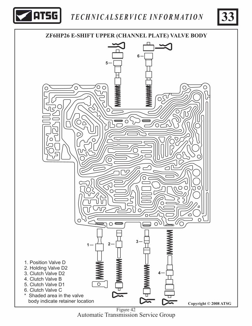
1. Position Valve D2. Holding Valve D2 3. Clutch Valve D24. Clutch Valve B5. Clutch Valve D16. Clutch Valve C* Shaded area in the valve body indicate retainer location
1
5
6
23
Automatic Transmission Service Group
33
ZF6HP26 E-SHIFT UPPER (CHANNEL PLATE) VALVE BODY
Figure 42
T E C H N I C A L S E R V I C E I N F O R M A T I O N
Copyright © 2008 ATSG
4
Automatic Transmission Service GroupFigure 43
34T E C H N I C A L S E R V I C E I N F O R M A T I O N
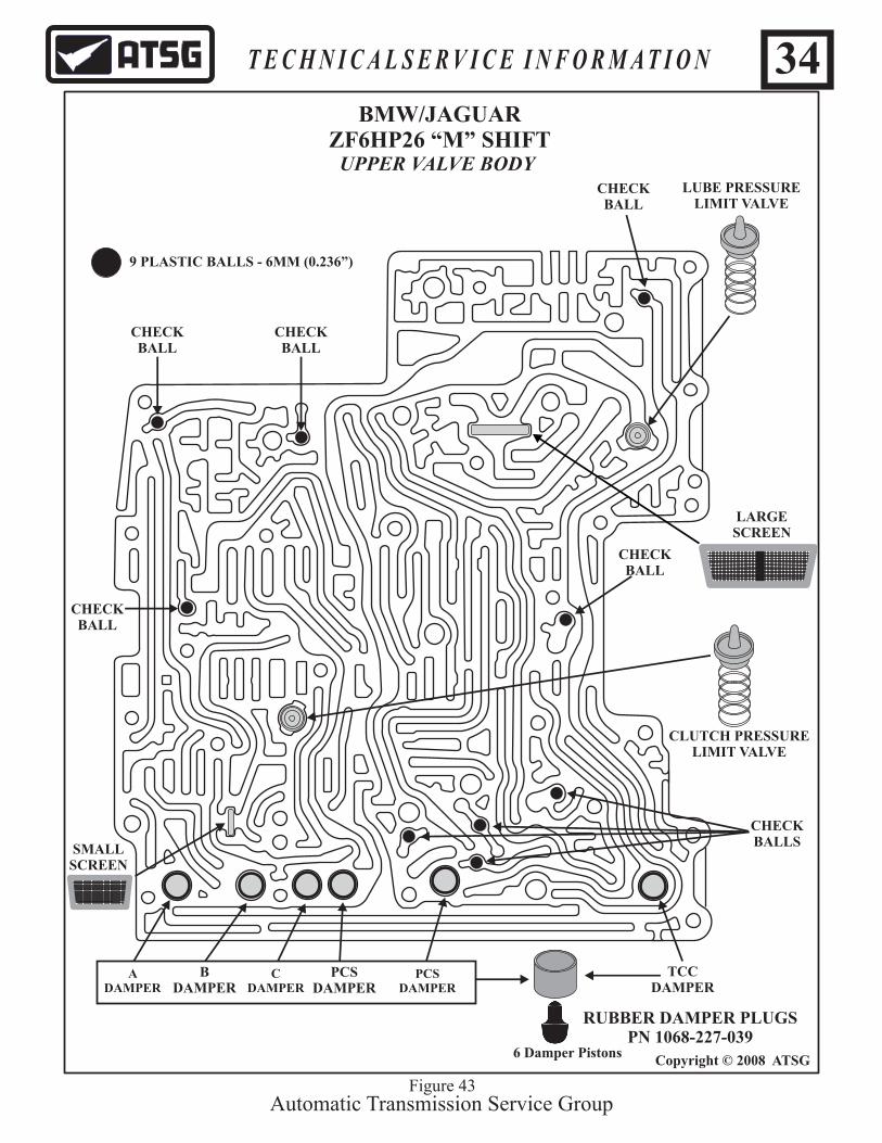
A DAMPER
B DAMPER
C DAMPER
PCS DAMPER
PCS DAMPER
TCC DAMPER
CHECKBALL
CHECKBALL
LUBE PRESSURELIMIT VALVE
CLUTCH PRESSURELIMIT VALVE
Copyright © 2008 ATSG
UPPER VALVE BODY
BMW/JAGUARZF6HP26 “M” SHIFT
SMALLSCREEN
6 Damper Pistons
9 PLASTIC BALLS - 6MM (0.236”)
CHECKBALL
CHECKBALL
CHECKBALL
CHECKBALLS
LARGESCREEN
RUBBER DAMPER PLUGSPN 1068-227-039

Automatic Transmission Service GroupFigure 44
35T E C H N I C A L S E R V I C E I N F O R M A T I O N
A DAMPER
B DAMPER
C DAMPER
PCS DAMPER
PCS DAMPER
TCC DAMPER
CHECKBALL
LUBE PRESSURELIMIT VALVE
CLUTCH PRESSURELIMIT VALVE
Copyright © 2008 ATSG
UPPER VALVE BODY
BMWZF6HP26 “E” SHIFT
6 DAMPER PISTONS
6 PLASTIC BALLS - 6MM (0.236”)
LARGESCREEN
CHECKBALL
CHECKBALLS
ROCKER
RUBBER DAMPER PLUGSPN 1068-227-039
Automatic Transmission Service GroupFigure 45
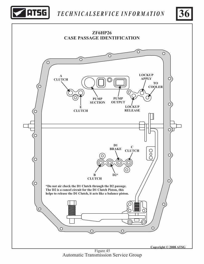
ZF6HP26CASE PASSAGE IDENTIFICATION
36T E C H N I C A L S E R V I C E I N F O R M A T I O N
Copyright © 2008 ATSG
PUMPSUCTION
PUMPOUTPUT
TOCOOLER
LOCKUPAPPLY
LOCKUPRELEASE
ECLUTCH
BCLUTCH
CCLUTCH
ACLUTCH
D2*
D1BRAKE
*Do not air check the D1 Clutch through the D2 passage.The D2 is a cancel circuit for the D1 Clutch Piston, thishelps to release the D1 Clutch, it acts like a balance piston.
Park
Reverse
Neutral
D 1st gear
D 2nd gear
D 3rd gear
D 4th gear
D 5th gear
D 6th gear
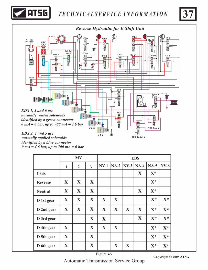
Reverse Hydraulic for E Shift Unit
Automatic Transmission Service Group
XX
X
X
XX
X
X
XX
XX
XX
XX X
X
X
X
X
X
XX
X
X
X
XX
X
X
X
X
X
X
X
X
X
X
X
X
X
X
X
X
X
X
X
X
X
X
X
X
X
X
XX
X
X
X
X
X
XX
X
X
X
X
X
X
X
X
ED
S 6
ED
S 5
ED
S 4
ED
S 3
ED
S 2
ED
S 1
EDS 1, 3 and 6 arenormally vented solenoidsidentified by a green connector 0 mA = 0 bar, up to 700 mA = 4.6 bar
EDS 2, 4 and 5 arenormally applied solenoidsidentified by a blue connector0 mA = 4.6 bar, up to 700 mA = 0 bar
XMV
2
MV
1
MV3
P
N
DA B C EA
M M
E
HV-A
CV-A
HV-B
CV-BCV-C CV-D1 CV-D2
HV-D1
HV-D2HV-E
CV-E
Sol. Fd.Limit V.
Pos.V
PRV
PS-V
SV-1
SV-2
Lube V
TCC Reg. V
TCC Switch V.
PCS
TCC
MV
1 2 3
EDS
NV-1 NA-2 NA-4NV-3 NA-5 NV-6
Figure 46
37
X X X* X*X X XX X
X X X
X X X
X
X
X*
X*
X*
X XX X X X* X*
X X* X*X X
X X* X*X X X
X X* X*X
X X* X*X XX
T E C H N I C A L S E R V I C E I N F O R M A T I O N
Copyright © 2008 ATSG

XX
X
X
X X X
X
X X XX
XX
XX
XX
X
X
X
X
XX X
X
X
X X
X
X
X
X
X
X
X
X
X
X
X
X
X
X
X
X
X
X
X
X
X
X
X
X
X
X
X X
X
X
X
X
X
XX
X X
X
X
X
X X
X
EDS 6
EDS 5
EDS 4
EDS 3
EDS 2
EDS 1
X
MV2
MV1
MV
3
P N
DA
BC
E
1st
gea
r h
ydra
uli
c fo
r E
Un
it
Automatic Transmission Service Group
MM
E
HV
-A
CV
-A
HV
-B
CV
-BC
V-C
CV
-D1
CV
-D2
HV
-D1
HV
-D2
HV
-E
CV
-E
So
l. F
d.
Lim
it V
.P
os
.V
PR
V
PS
-V
SV
-1
SV
-2
Lu
be
V
TC
C R
eg
. V
TC
C S
wit
ch
V.
PC
S
TC
C
Figure 47
38
In f
irst
gea
r al
l of
the
no
rmal
ly v
ente
d M
V s
olen
oids
are
en
erg
ized
su
pp
lyin
g p
ress
ure
to t
hei
r re
spec
tive
cir
cuit
s.
ED
S 1
wh
ich
is
a no
rmal
ly v
ente
d s
ole
no
id i
s en
erg
ized
sup
plyi
ng p
ress
ure
to
its
resp
ecti
ve c
ircu
it.
ED
S 2
wh
ich
is
a no
rmal
ly a
pp
lied
so
len
oid
is
ener
gize
d bl
ock
ing
pre
ssur
e fr
om i
ts r
esp
ecti
ve c
ircu
it.
ED
S 3
wh
ich
is
a no
rmal
ly v
ente
d s
ole
no
id i
s n
ot
ener
gize
d ve
nti
ng
pre
ssur
e fr
om i
ts r
esp
ecti
ve c
ircu
it.
ED
S 4
wh
ich
is
a no
rmal
ly a
pp
lied
so
len
oid
is
no
t en
ergi
zed
sup
plyi
ng p
ress
ure
to
its
resp
ecti
ve
circ
uit.
D 1
st g
ear
XX
XX
*X
*
MV
1
2
3
P-E
DS
NV
-1N
A-2
NA
-4N
V-3
NA
-5N
V-6
XX
GE
AR
A
B
C
D/E
T E C H N I C A L S E R V I C E I N F O R M A T I O N
Copyright © 2008 ATSG

XX
X
X
X X X
X
X X XX
XX
XX
XX
X
X
X
X
XX X
X
X
X X
X
X
X
X
X
X
X
X
X
X
X
X
X
X
X
X
X
X
X
X
X
X
X
X
X
X
X X
X
X
X
X
X
XX
X X
X
X
X
X X
X
EDS 6
EDS 5
EDS 4
EDS 3
EDS 2
EDS 1
X
MV2
MV1
MV
3
P N
DA
BC
E
2nd
gea
r h
ydra
uli
c fo
r E
Un
it
Automatic Transmission Service Group
MM
E
HV
-A
CV
-A
HV
-B
CV
-BC
V-C
CV
-D1
CV
-D2
HV
-D1
HV
-D2
HV
-E
CV
-E
So
l. F
d.
Lim
it V
.P
os
.V
PR
V
PS
-V
SV
-1
SV
-2
Lu
be
V
TC
C R
eg
. V
TC
C S
wit
ch
V.
PC
S
TC
C
Figure 48
39
D 2
nd
gea
rX
XX
X*
X*
MV
1
2
3
P-E
DS
NV
-1N
A-2
NA
-4N
V-3
NA
-5N
V-6
XX
GE
AR
C
XX
A
B
C
D/E
In s
eco
nd
gea
r
ED
S 1
wh
ich
is
a no
rmal
ly v
ente
d s
ole
no
id i
s en
erg
ized
sup
plyi
ng p
ress
ure
to
its
resp
ecti
ve c
ircu
it.
ED
S 2
wh
ich
is
a no
rmal
ly a
pp
lied
so
len
oid
is
ener
gize
d bl
ock
ing
pre
ssur
e fr
om i
ts r
esp
ecti
ve c
ircu
it.
ED
S 3
wh
ich
is
a no
rmal
ly v
ente
d s
ole
no
id i
s en
erg
ized
sup
plyi
ng p
ress
ure
to
its
resp
ecti
ve c
ircu
it.
ED
S 4
wh
ich
is
a no
rmal
ly a
pp
lied
so
len
oid
is
ener
gize
d bl
ock
ing
pre
ssur
e to
its
res
pec
tiv
e ci
rcu
it.
all
of t
he n
orm
ally
ven
ted
MV
so
leno
ids
are
ener
giz
ed s
up
ply
ing
pre
ssur
e to
th
eir
resp
ecti
ve c
ircu
its.
T E C H N I C A L S E R V I C E I N F O R M A T I O N
Copyright © 2008 ATSG

XX
X
X
X X X
X
X X XX
XX
XX
XX
X
X
X
X
XX X
X
X
X X
X
X
X
X
X
X
X
X
X
X
X
X
X
X
X
X
X
X
X
X
X
X
X
X
X
X X
X
X
X
X
X
XX
X X
X
X
X
X X
X
EDS 6
EDS 5
EDS 4
EDS 3
EDS 2
EDS 1
X
MV2
MV1
MV
3
P N
DA
BC
E
3rd
gear
hyd
rau
lic
for
E U
nit
Automatic Transmission Service Group
X
MM
E
HV
-A
CV
-A
HV
-B
CV
-BC
V-C
CV
-D1
CV
-D2
HV
-D1
HV
-D2
HV
-E
CV
-E
So
l. F
d.
Lim
it V
.P
os
.V
PR
V
PS
-V
SV
-1
SV
-2
Lu
be
V
TC
C R
eg
. V
TC
C S
wit
ch
V.
PC
S
TC
C
Figure 49
D 3
rd g
ear
XX
*X
*
MV
1
2
3
P-E
DS
NV
-1N
A-2
NA
-4N
V-3
NA
-5N
V-6
X
GE
AR
X
A
B
C
D/E
In t
hir
d g
ear
norm
ally
ven
ted
MV
sol
eno
ids
1 an
d 2
tu
rn o
ff v
enti
ng
th
eir
circ
uit
s w
hil
e 3
rem
ain
s en
erg
ized
. E
DS
1 w
hic
h i
s a
norm
ally
ven
ted
so
len
oid
is
ener
giz
ed s
uppl
ying
pre
ssu
re t
o it
s re
spec
tive
cir
cuit
.E
DS
2 w
hic
h i
s a
norm
ally
ap
pli
ed s
ole
no
id i
s n
ot
ener
gize
d s
uppl
ying
pre
ssu
re t
o it
s re
spec
tiv
e ci
rcui
t.E
DS
3 w
hic
h i
s a
norm
ally
ven
ted
so
len
oid
is
no
t en
ergi
zed
exh
aust
s pr
essu
re t
o it
s re
spec
tiv
e ci
rcui
t.E
DS
4 w
hic
h i
s a
norm
ally
ap
pli
ed s
ole
no
id i
s en
ergi
zed
blo
ckin
g p
ress
ure
to i
ts r
esp
ecti
ve
circ
uit
.
T E C H N I C A L S E R V I C E I N F O R M A T I O N
Copyright © 2008 ATSG
40
XX
X
X
X X X
X
X X XX
XX
XX
XX
X
X
X
X
XX X
X
X
X X
X
X
X
X
X
X
X
X
X
X
X
X
X
X
X
X
X
X
X
X
X
X
X
X
X
X X
X
X
X
X
X
XX
X X
X
X
X
X X
X
EDS 6
EDS 5
EDS 4
EDS 3
EDS 2
EDS 1
X
MV2
MV1
MV
3
P N
DA
BC
E
4th
gea
r h
ydra
uli
c fo
r E
Un
it
Automatic Transmission Service Group
X
MM
E
HV
-A
CV
-A
HV
-B
CV
-BC
V-C
CV
-D1
CV
-D2
HV
-D1
HV
-D2
HV
-E
CV
-E
So
l. F
d.
Lim
it V
.P
os
.V
PR
V
PS
-V
SV
-1
SV
-2
Lu
be
V
TC
C R
eg
. V
TC
C S
wit
ch
V.
PC
S
TC
C
Figure 50
D 4
th g
ear
XX
*X
*
MV
1
2
3
P-E
DS
NV
-1N
A-2
NA
-4N
V-3
NA
-5N
V-6
X
GE
AR
A
B
C
D/E
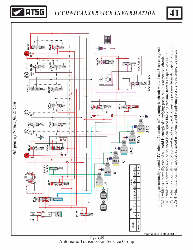
In f
our
th g
ear
no
rmal
ly v
ente
d M
V s
olen
oid
2 r
emai
ns o
ff v
enti
ng i
ts c
ircu
it w
hil
e 1
and
3 ar
e en
erg
ized
. E
DS
1 w
hic
h i
s a
norm
ally
ven
ted
so
len
oid
is
ener
giz
ed s
uppl
ying
pre
ssu
re t
o it
s re
spec
tive
cir
cuit
.E
DS
2 w
hic
h i
s a
norm
ally
ap
pli
ed s
ole
no
id i
s en
ergi
zed
blo
ckin
g p
ress
ure
from
its
res
pec
tive
cir
cuit
.E
DS
3 w
hic
h i
s a
norm
ally
ven
ted
so
len
oid
is
no
t en
ergi
zed
exh
aust
ing
pres
sure
fro
m i
ts r
esp
ecti
ve
circ
uit
.E
DS
4 w
hic
h i
s a
norm
ally
ap
pli
ed s
ole
no
id i
s n
ot
ener
gize
d s
uppl
ying
pre
ssu
re t
o it
s re
spec
tiv
e ci
rcui
t.
XX
T E C H N I C A L S E R V I C E I N F O R M A T I O N
Copyright © 2008 ATSG
41

XX
X
X
X X X
X
X X XX
XX
XX
XX
X
X
X
X
XX X
X
X
X X
X
X
X
X
X
X
X
X
X
X
X
X
X
X
X
X
X
X
X
X
X
X
X
X
X
X X
X
X
X
X
X
XX
X X
X
X
X
X X
X
EDS 6
EDS 5
EDS 4
EDS 3
EDS 2
EDS 1
X
MV2
MV1
MV
3
P N
DA
BC
E
5th
gea
r h
ydra
uli
c fo
r E
Un
it
Automatic Transmission Service Group
X
MM
E
HV
-A
CV
-A
HV
-B
CV
-BC
V-C
CV
-D1
CV
-D2
HV
-D1
HV
-D2
HV
-E
CV
-E
So
l. F
d.
Lim
it V
.P
os
.V
PR
V
PS
-V
SV
-1
SV
-2
Lu
be
V
TC
C R
eg
. V
TC
C S
wit
ch
V.
PC
S
TC
C
Figure 51
PC
S
TC
C
D 5
th g
ear
XX
*X
*
MV
1
2
3
P-E
DS
NV
-1N
A-2
NA
-4N
V-3
NA
-5N
V-6
GE
AR
A
B
C
D/E
In f
ifth
gea
r no
rmal
ly v
ente
d M
V s
ole
no
id 2
rem
ains
off
ven
tin
g it
s ci
rcu
it w
hile
1 a
nd
3 a
re e
nerg
ized
. E
DS
1 w
hic
h i
s a
norm
ally
ven
ted
so
len
oid
is
no
t en
ergi
zed
exh
aust
ing
pres
sure
fro
m i
ts r
esp
ecti
ve
circ
uit
.E
DS
2 w
hic
h i
s a
norm
ally
ap
pli
ed s
ole
no
id i
s n
ot
ener
gize
d s
uppl
ying
pre
ssu
re t
o it
s re
spec
tiv
e ci
rcui
t.E
DS
3 w
hic
h i
s a
norm
ally
ven
ted
so
len
oid
is
no
t en
ergi
zed
exh
aust
ing
pres
sure
fro
m i
ts r
esp
ecti
ve
circ
uit
.E
DS
4 w
hic
h i
s a
norm
ally
ap
pli
ed s
ole
no
id i
s n
ot
ener
gize
d s
uppl
ying
pre
ssu
re t
o it
s re
spec
tiv
e ci
rcui
t.
X
T E C H N I C A L S E R V I C E I N F O R M A T I O N
Copyright © 2008 ATSG
42

XX
X
X
X X X
X
X X XX
XX
XX
XX
X
X
X
X
XX X
X
X
X X
X
X
X
X
X
X
X
X
X
X
X
X
X
X
X
X
X
X
X
X
X
X
X
X
X
X X
X
X
X
X
X
XX
X X
X
X
X
X X
X
EDS 6
EDS 5
EDS 4
EDS 3
EDS 2
EDS 1
X
MV2
MV1
MV
3
P N
DA
BC
E
6th
gea
r h
ydra
uli
c fo
r E
Un
it
Automatic Transmission Service Group
X
MM
E
HV
-A
CV
-A
HV
-B
CV
-BC
V-C
CV
-D1
CV
-D2
HV
-D1
HV
-D2
HV
-E
CV
-E
So
l. F
d.
Lim
it V
.P
os
.V
PR
V
PS
-V
SV
-1
SV
-2
Lu
be
V
TC
C R
eg
. V
TC
C S
wit
ch
V.
PC
S
TC
C
Figure 52
D 6
th g
ear
XX
*X
*
MV
1
2
3
P-E
DS
NV
-1N
A-2
NA
-4N
V-3
NA
-5N
V-6
GE
AR
A
B
C
D/E
In s
ixth
gea
r n
orm
ally
ven
ted
MV
sol
enoi
d 2
rem
ains
off
ven
ting
its
cir
cuit
wh
ile
1 an
d 3
are
ener
giz
ed.
ED
S 1
wh
ich
is
a no
rmal
ly v
ente
d s
ole
no
id i
s n
ot
ener
gize
d ex
hau
stin
g pr
essu
re f
rom
its
res
pec
tiv
e ci
rcu
it.
ED
S 2
wh
ich
is
a no
rmal
ly a
pp
lied
so
len
oid
is
ener
gize
d bl
ock
ing
pre
ssur
e fr
om i
ts r
esp
ecti
ve c
ircu
it.
ED
S 3
wh
ich
is
a no
rmal
ly v
ente
d s
ole
no
id i
s en
erg
ized
sup
plyi
ng p
ress
ure
to
its
resp
ecti
ve c
ircu
it.
ED
S 4
wh
ich
is
a no
rmal
ly a
pp
lied
so
len
oid
is
no
t en
ergi
zed
sup
plyi
ng p
ress
ure
to
its
resp
ecti
ve
circ
uit.
XX
X
T E C H N I C A L S E R V I C E I N F O R M A T I O N
Copyright © 2008 ATSG
43
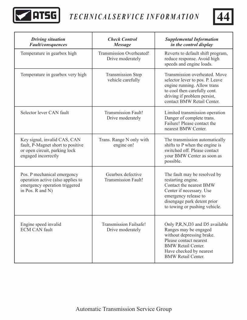
Temperature in gearbox high Transmission Overheated!Drive moderately
Reverts to default shift program,reduce response. Avoid highspeeds and engine loads.
Temperature in gearbox very high Transmission Stopvehicle carefully
Transmission overheated. Moveselector lever to pos. P. Leaveengine running. Allow trans to cool then carefully cont.driving if problem persist,contact BMW Retail Center.
Selector lever CAN fault Transmission Fault!Drive moderately
Limited transmission operationDanger of complete trans.Failure! Please contact thenearest BMW Center.
Key signal, invalid CAS, CANfault, P-Magnet short to positiveor open circuit, parking lockengaged incorrectly
Trans. Range N only withengine on!
The transmission automaticallyshifts to P when the engine isswitched off. Please contact your BMW Center as soon aspossible.
Pos. P mechanical emergencyoperation active (also applies toemergency operation triggeredin Pos. R and N)
Gearbox defectiveTransmission Fault!
The fault may be resolved byrestarting engine. Contact the nearest BMW Center if necessary. Use emergency release to disengage park detent priorto towing or pushing vehicle.
Engine speed invalidECM CAN fault
Transmission Failsafe!Drive moderately
Only P,R,N,D3 and D5 availableRanges may be engaged without depressing brake.Please contact nearest BMW Retail Center.Have checked by nearestBMW Retail Center.
Automatic Transmission Service Group
Driving situationFault/consquences
Check ControlMessage
Supplemental Informationin the control display
T E C H N I C A L S E R V I C E I N F O R M A T I O N 44
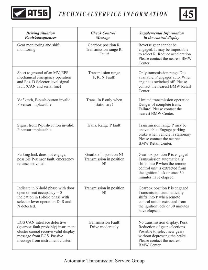
Gear monitoring and shift monitoring
Gearbox position R.Transmission range R,
Fault!
Reverse gear cannot be engaged. It may be impossibleto select R. Reduce acceleration.Please contact the nearest BMWCenter.
Short to ground of an MV, EPSmechanical emergency operationand Pos. D Selector level signalfault (CAN and serial line)
Transmission rangeP, R, N Fault!
Only transmission range D isavailable. P engages auto. Whenengine is switched off. Please contact the nearest BMW RetailCenter.
V>3km/h, P-push-button invalid.P-sensor implausible
Trans. In P only whenstationary!
Limited transmission operationDanger of complete trans.Failure! Please contact thenearest BMW Center.
Signal from P-push-button invalid.P-sensor implausible
Trans. Range P fault! Transmission range P may beunavailable. Engage parkingbrake when vehicle is stationaryPlease contact the nearest BMW Retail Center.
Parking lock does not engage,possible P-sensor fault, emergencyrelease activated.
Gearbox in position N!Transmission in position
N!
Gearbox position P is engaged Transmission automaticallyshifts into P when the remotecontrol unit is extracted from the ignition lock or once 30minutes have elapsed.
Indicate in N-hold phase with dooropen or seat occupancy = 0indication in H-hold phase withselector lever operation D, R and N detected.
Transmission in positionN!
Gearbox position P is engagedTransmission automatically shifts into P when remotecontrol unit is extracted from the ignition lock or 30 minuteshave elapsed.
EGS CAN interface defective (gearbox fault probably) instrumentcluster cannot receive valid displaymessage from EGS. Passive message from instrument cluster.
Transmission Fault!Drive moderately
No transmission display. Poss.Reduction of gear selections.Possible to select new gearswithout depressing the brake.Please contact the nearestBMW Center.
Automatic Transmission Service Group
Driving situationFault/consquences
Check ControlMessage
Supplemental Informationin the control display
T E C H N I C A L S E R V I C E I N F O R M A T I O N 45

Indicate at terminal 15 on and dooropen or seat occupancy = 0
Gearbox in position N!Transmission in position N!
Gearbox position P is engaged.
Shift lock note To engage gear brake Only transmission range D isavailable. P engages auto. Whenengine is switched off. Please contact the nearest BMW RetailCenter.
Brake signal invalidBrake signal implausible
Gear engage withoutbrake possible!
Before engaging gear, press brake.When leaving the vehicle, switchoff the engine. Accident Hazard!Please contact your BMW RetailCenter as soon as possible.
Indication in the event of sloppyoperation or P-push-button faulty
Repeat gear selection Transmission range P may beunavailable. Engage parkingbrake when vehicle is stationaryPlease contact the nearest BMW Retail Center.
Message before N-hold phaseelapse (30 minutes)
Transmission position Pengaging!
To maintain transmission range N, press selector leverwithin 10 seconds to position N.
Gear monitoringShift monitoring
Transmission Failsafe!Drive moderately
Transmission failsafe programPossible reduced acceleration.Please contact the nearest BMWCenter.
Ignition on and N engine = 0and gearbox Position P and selector lever push to N.
Position R, N, D only withinengine on.
Automatic Transmission Service Group
Driving situationFault/consquences
Check ControlMessage
Supplemental Informationin the control display
T E C H N I C A L S E R V I C E I N F O R M A T I O N 46

P0605P0606P0610
P0641P0651P0666P0701
P0702
P0705P0706
P0709P0710P0711P0715P0720
P0721P0729
P0730
P0731
P0732
P0733
P0734
P0735
P0736
EPROM FLASH, ChecksumWatchdog locking mechanismIncorrect configuration or calibration loaded
Sensor supply voltageEDS and MV solenoid supplySubstrate Temp. Sensor open or short circuitCombination of impossible substitute functions
Undervoltage
Position switch open or short circuitImplausible J Gate Position (Jaguar)
Intermediate positionFluid Temp Sensor open or short circuitFluid Temp Monitoring out of rangeTurbine Speed Signal open or short circuitOutput Speed Signal open or short circuit
Reverse Gear Ratio Errorth6 Gear Ratio Error
Gear Ratio Fault
st1 Gear Ratio Error
nd2 Gear Ratio Error
rd3 Gear Ratio Error
th4 Gear Ratio Error
th5 Gear Ratio Error
Reverse Gear Ratio Error
New TCM and ValvebodyNew TCM and ValvebodyShould never be seen - mismatch with ECM and TCM
New TCM and ValvebodyNew TCM and ValvebodyNew TCM and ValvebodyYou will see another code as well (ATF or OSS)
Engine must be running to log code - charging fault
New TCM and ValvebodyNo manual side operation of J-Gate-test J-Gate - check cable set up
Should not be seenNew TCM and ValvebodyNew TCM and ValvebodyNew TCM and ValvebodyCompare output speed with wheel speed - New TCM and Valvebody
Output speed gradient faultCheck oil level and condition - replace transmission
Check oil level and condition - replace transmission
Check oil level and condition - replace transmission
Check oil level and condition - replace transmission
Check oil level and condition - replace transmission
Check oil level and condition - replace transmission
Check oil level and condition - replace transmission
Incorrect ratio calculated for revers - check oil level and condition - replace transmission
Automatic Transmission Service Group
DTC DTC DESCRIPTION COMMENTS
T E C H N I C A L S E R V I C E I N F O R M A T I O N 47

P0740P0741P0743P0750P0753P0755P0758P0760P0763P0765P0768P0770P0773
P0780
P0781
P0782
P0783
P0784
P0787P0788P0825P0829
P1571P1603
P1605P1749
P1774P1783P1794P1796P1797P1798P1799
EDS 6 solenoid open or short circuitTCC stuck open, excessive slipEDS 6 performance faultEDS 1 solenoid open or short circuitEDS 1 solenoid performance faultEDS 2 solenoid open or short circuitEDS 2 solenoid performance faultEDS 3 solenoid open or short circuitEDS 3 solenoid performance faultEDS 4 solenoid open or short circuitEDS 4 solenoid performance faultEDS 5 solenoid open or short circuitEDS 5 solenoid performance fault
Car load fault, incorrect calculation during shift
Gear load 1-2 or 2-1
Gear load 2-3 or 3-2
Gear load 3-4 or 4-3
Gear load 4-5 or 5-4
MV1 solenoid open or short circuitMV1 solenoid performance faultJ Gate Plausibility in position R/D (Jaguar) Gear load 5-6 or 6-5
Brake Pedal SignalEEPROM Communications internal error
Battery buffered RAM’P and N signal invalid
CAN message J-Gate time-out (Jaguar)Over Temperature Shut downPower supply open or short circuitCAN bus off, network faultCAN timeout EMSCAN timeout INSTCAN timeout ABS
New TCM and ValvebodyNew TCM and ValvebodyNew TCM and ValvebodyNew TCM and ValvebodyNew TCM and ValvebodyNew TCM and ValvebodyNew TCM and ValvebodyNew TCM and ValvebodyNew TCM and ValvebodyNew TCM and ValvebodyNew TCM and ValvebodyNew TCM and ValvebodyNew TCM and Valvebody
Check oil level and condition -replace transmission
Check oil level and condition - replace transmission
Check oil level and condition - replace transmission
Check oil level and condition - replace transmission
Check oil level and condition - replace transmission
New TCM and ValvebodyNew TCM and ValvebodyTest J-Gate (Jaguar)Check oil level and condition - replace transmission
Test ECM InputsClear code first and retry -New TCM and Valvebody
New TCM and ValvebodyCarry out pin pint test-used by EMS for starting
Check networkCheck for cause of overheatingCheck fuse feed etc.Harness or ModuleCheck networkCheck networkCheck network
Automatic Transmission Service Group
T E C H N I C A L S E R V I C E I N F O R M A T I O N 48

Input/Turbine Speed Sensor 'A' CircuitOutput Speed Sensor CircuitGear 1 Incorrect RatioGear 2 Incorrect RatioGear 3 Incorrect RatioGear 4 Incorrect RatioGear 5 Incorrect RatioTorque Converter Clutch Circuit/OpenTorque Converter Clutch Circuit Performance or Stuck OffTorque Converter Clutch Circuit ElectricalPressure Control Solenoid 'A'Pressure Control Solenoid 'A' ElectricalShift Solenoid 'A' Performance or Stuck OffShift Solenoid 'A' ElectricalShift Solenoid 'B' Performance or Stuck OffShift Solenoid 'B' ElectricalShift Solenoid 'C' Performance or Stuck OffShift Solenoid 'C' ElectricalPressure Control Solenoid 'B'Pressure Control Solenoid 'B' Electrical1-2 Shift2-3 Shift3-4 Shift4-5 ShiftPressure Control Solenoid 'C'Pressure Control Solenoid 'C' ElectricalDouble Error Position Information CAN / Serial LineCombination Substitute FunctionCAN Timeout Control ModuleCAN Timeout ASC/DSCCAN Engine SpeedEngine Over-speed ConditionGear 6 Incorrect RatioPressure Control Solenoid 'E' Electrical (M44/M52: Brake Band Electrical)Pressure Control Solenoid 'E'CAN-BUS MonitoringPressure Control Solenoid 'D' ElectricalPressure Control Solenoid 'D'CAN Torque Interface PlausibilityInternal Transmission Control Module Memory Checksum/EPROM ErrorInternal Transmission Control Module Memory Checksum/EEPROM ErrorInternal Transmission Control Module Watchdog ErrorETC Cut-Off due to Over-temperature ConditionShift Solenoid 'A' Low InputShift Solenoid 'B' Low InputShift Solenoid 'C' Low InputShift Solenoid 'A' or 'B' Mechanically StuckInput/Turbine Speed Sensor Circuit High
P0715P0720P0731P0732P0733P0734P0735P0740P0741P0743P0745P0748P0751P0753P0756P0758P0761P0763P0775P0778P0781P0782P0783P0784P0795P0798P1701P1702P1720P1721P1727P1728P1736P1743P1745P1747P1753 P1755 P1771 P1790P1791P1792P1793P1801P1802P1803P1806P1810
20200 20201 20301 20302 20303 20304 20305 20005 20307 20005 20000 20000 20100 20100 20101 20101 20102 20102 20001 20001 20311 20312 20313 20314 20002 20002 20700 20701 20800 20801 20903 20336 20306 20004 20004 52999 20003 20003 20901 20400 20401 20402 20330 20100 20101 20102 20105 20200
P Code Code Description BMW-FC
Automatic Transmission Service Group
T E C H N I C A L S E R V I C E I N F O R M A T I O N 49

Input/Turbine Speed Sensor Circuit LowOutput Speed Sensor Circuit High InputOutput Speed Sensor Circuit Low InputOutput Speed Sensor Gradient Too HighPressure Control Solenoid Current Error in P/R/NPressure Control Solenoid 'A" Circuit HighPressure Control Solenoid 'B' Circuit HighPressure Control Solenoid 'C' Circuit HighPressure Control Solenoid 'D' Circuit HighPressure Control Solenoid 'E' Circuit HighTorque Converter Clutch Circuit HighPressure Control Solenoid 'A' Circuit LowPressure Control Solenoid 'B' Circuit LowPressure Control Solenoid 'C' Circuit LowPressure Control Solenoid 'D' Circuit LowPressure Control Solenoid 'E' Circuit LowTorque Converter Clutch Circuit Low2-1 Shift3-2 Shift4-3 Shift5-4 Shift6-5 Shift2-1 Shift Circuit High3-2 Shift Circuit High4-3 Shift Circuit High5-4 Shift Circuit High6-5 Shift Circuit High1-2 Shift Circuit High2-3 Shift Circuit High3-4 Shift Circuit High4-5 Shift Circuit High5-6 Shift Circuit High5-6 ShiftCAN Timeout Instrument Pack during Operation Parking Interlock Emergency ReleaseSystem VoltageSystem Voltage High InputSystem Voltage Low InputSupply Voltage Pressure Control Solenoid/Shift Solenoid Circuit HighSupply Voltage Pressure Control Solenoid/Shift Solenoid Circuit LowSupply Voltage Pressure Control Solenoid/Shift Solenoid No SignalSupply Voltage Pressure Control Solenoid/Shift SolenoidSupply Voltage Sensors High InputSupply Voltage Sensors Low Input
P1811 P1812 P1813 P1814 P1830 P1831 P1832 P1833 P1834 P1835 P1836 P1841 P1842 P1843 P1844 P1845 P1846 P1861 P1862 P1863 P1864 P1865 P1871 P1872 P1873 P1874 P1875 P1881 P1882 P1883 P1884 P1885 P1886 P1888 P1890 P1891 P1892 P1893 P1894 P1895 P1896 P1897 P1898
20200202012020120203200062000020001200022000320004200052000020001200022000320004200052031620317203182031920320203162031720318203192032020311203122031320314203152031520337
205002050020500205012050120501205012050220502
P Code Code Description BMW-FC
Automatic Transmission Service Group
50T E C H N I C A L S E R V I C E I N F O R M A T I O N
ZF6HP26
TRANSMISSION FLUID LEAK
COMPLAINT:
CAUSE:
CORRECTION:
The transmission appears to be leaking from the front seal (Refer to Figure 1).
The vent is routed to the bell-housing in a similar fashion as Ford’s 5R55S&W transmissions and could be mistaken as a front seal leak should fluid be pushed out of the vent.
Check the fluid and level to determine if the transmission is either over filled, aerated or overheated. If overfull, correct level. If aerated it could be that it was so overfull that the gear train churned the fluid. Once the correct fluid level has been obtained, if the fluid continues to aerate the pump is sucking in air from either the filter seal, cracked seal neck or the pump is taking in air between the pump halves or from the pump to case surface area. If the fluid has overheated, suspect converter clutch apply issues or a defective converter.
Automatic Transmission Service Group
T E C H N I C A L S E R V I C E I N F O R M A T I O N 51

ZF6HP26 TRANSMISSION FLUID LEAK
MISTAKEN FRONT SEAL LEAK
VENT TUBEVENT
Figure 1 Copyright © 2008 ATSG
Automatic Transmission Service Group
T E C H N I C A L S E R V I C E I N F O R M A T I O N 52
ZF6HP26
TRANSMISSION FLUID LEAK
COMPLAINT:
CAUSE:
CORRECTION:
SERVICE INFORMATION:
The transmission appears to be leaking from the pan gasket, (Refer to Figure 1).
The Mechatronic Sealing Sleeve o-rings (Refer to Figure 2) is leaking and running down along the pan rail giving the appearance that the pan gasket is leaking.
Replace the Mechatronic Sealing Sleeve.
Mechatronic Sealing Sleeve.......................................................ZF Part Number 0501212190Oil Pan/Filter Assembly For Manual Valve Body.....................ZF Part Number 0501215789
Automatic Transmission Service Group
T E C H N I C A L S E R V I C E I N F O R M A T I O N 53

ZF6HP26 TRANSMISSION FLUID LEAK
Figure 1
THE LEAK APPEARS TO BE COMINGFROM THE PAN GASKET AREA
ALIGNMENTTAB
"O" RINGS"LIP" SEAL
MECHATRONIC SEALING SLEEVE
Automatic Transmission Service Group
T E C H N I C A L S E R V I C E I N F O R M A T I O N
Copyright © 2008 ATSG
Copyright © 2008 ATSG
54
Figure 2

Automatic Transmission Service Group
T E C H N I C A L S E R V I C E I N F O R M A T I O N
JAGUAR ZF6HP26
HARSH KICKDOWN
Copyright © 2008 ATSG
COMPLAINT:
CAUSE:
CORRECTION:
Under medium to hard throttle, upshift and kickdown shifts are harsh. This could be intermittent and could be worse when hot.
A crack has developed in the intake snorkel to the Mass Airflow Sensor (MAF), See Figure 1, this creates a miscalculation of engine load thereby causing the shift complaints.
Repair or replace the air intake snorkel.
Figure 1
MAFSENSOR
CRACKDEVELOPS
HERE
55

Automatic Transmission Service Group
T E C H N I C A L S E R V I C E I N F O R M A T I O N
Copyright © 2008 ATSG
56BMW ZF6HP26

Automatic Transmission Service Group
T E C H N I C A L S E R V I C E I N F O R M A T I O N
Copyright © 2008 ATSG
57BMW ZF6HP26
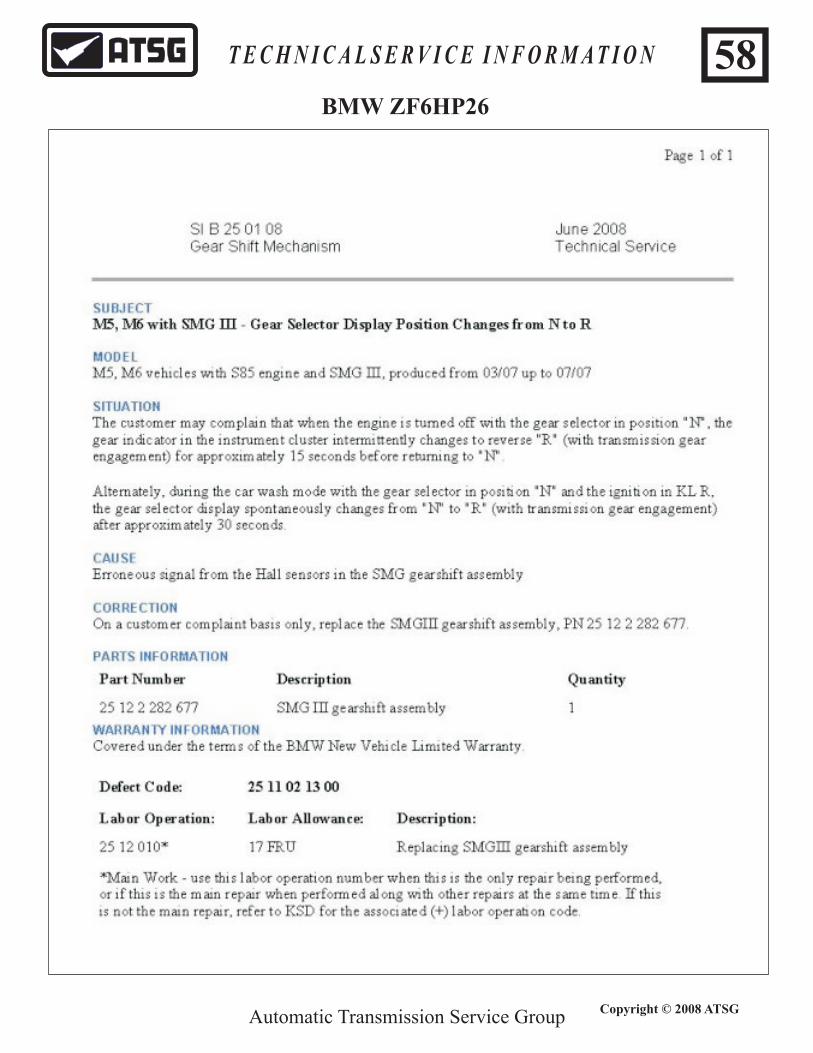
Automatic Transmission Service Group
T E C H N I C A L S E R V I C E I N F O R M A T I O N
Copyright © 2008 ATSG
58BMW ZF6HP26

Automatic Transmission Service Group
T E C H N I C A L S E R V I C E I N F O R M A T I O N
Copyright © 2008 ATSG
59BMW ZF6HP26

Automatic Transmission Service Group
T E C H N I C A L S E R V I C E I N F O R M A T I O N
Copyright © 2008 ATSG
60BMW ZF6HP26

Automatic Transmission Service Group
T E C H N I C A L S E R V I C E I N F O R M A T I O N
Copyright © 2008 ATSG
61BMW CHASSIS ID
1988
1989
1990
1991
1992
1993
1994
1995
1996
1997
1998
1999
2000
2001
2002
2003
2004
2005
2006
2007
VEH
ICLE
MO
DEL
BMW
CH
ASS
IS ID
ENTI
FIC
ATI
ON
31
8i
E30
E36
E36
E36
E36
E36
E36
31
8i C
onve
rtib
le
31
8is
E30
E30
E36
E36
E36
E36
E36
E36
E36
E36
E36
E36
31
8ti
E36
/5E3
6/5
E36
/5E3
6/5
E36
/5
32
3C
iE4
6E4
6
32
3C
i Co
nve
rtib
le
E46
E46
32
3i
E46
E46
32
3i C
onve
rtib
le
32
3is
E46
E46
32
5
32
5
E30
E30
32
5E9
0/9
1
32
5C
i Co
nve
rtib
leE4
6E4
6
E46
E46
E46
E46
E46
32
5C
iE4
6E4
6
32
5i
E30
E30
E30
E36
E36
E36
E36
E46
E46
E46
32
5i C
onve
rtib
leE3
0E3
0E3
0E3
0E3
0E3
0E3
6E3
63
25
i Sp
ort
Wa
go
n
E46
E46
E46
32
5is
E30
E30
E30
E30
E36
E36
E36
E36
32
5ix
E30
32
5ix
AW
DE3
0E3
0E3
0E3
0
32
5xi
Se
da
n3
25
xi S
po
rt W
ag
on
E46
E46
E46
E46
E46
32
8E9
0/1
/2/3
32
8C
iE4
6
32
8i
E36
E36
E36
E46
E46
32
8i C
onve
rtib
leE3
6E3
6E3
6E3
6
32
8is
E36
E36
E36
E36
33
0E4
6
E90
33
0
33
0C
i Co
nve
rtib
leE4
6E4
6E4
63
30
Ci C
oup
eE4
6E4
6E4
6
33
0i
33
0xi
AW
D S
ed
an
E46
E46
E46
E46
E46
E46

Automatic Transmission Service Group
T E C H N I C A L S E R V I C E I N F O R M A T I O N
Copyright © 2008 ATSG
BMW CHASSIS ID1988
1989
1990
1991
1992
1993
1994
1995
1996
1997
1998
1999
2000
2001
2002
2003
2004
2005
2006
2007
VEH
ICLE
MO
DEL
BMW
CH
ASS
IS ID
ENTI
FIC
ATIO
N
E90/
2/3
335
525
E60
E60
E60
E60
525i
E34
E34
E34
E34
E34
E34
E34
525i
Se
da
nE3
9E3
9E3
952
5i S
po
rt W
ag
on
E39
E39
E39
525i
To
urin
g W
ag
on
E34/
2E3
4/2
E34/
2
528e
E28
528i
E39
E39
E39
528i
Sp
ort
Wa
go
nE3
9E3
9
530
E60
E60
E60/
1E6
0/1
530i
E34
E34
530i
Se
da
nE3
9E3
9E3
953
0i T
our
ing
Wa
go
n
535i
E34/
3E3
4/3
E28
E34
E34
E34
E34
E34
535i
sE2
8
540i
E34
E34
540i
Se
da
nE3
9E3
9E3
9
540i
Sp
ort
Wa
go
n
E39
E39
E39
E39
E39
540i
E39
E39
E39
E39
545
E60
E60
550
E60
E60
635c
siE2
4E2
464
5E6
3/64
E63/
64
650
E63/
64E6
3/64
735i
E32
E32
E32
E32
E32
735i
LE3
2/2
E32/
2E3
2/2
740i
E32
E32
E38
E38
E38
E38
E38
E38
740i
LE3
2/2
E32/
2E3
8E3
8E3
8E3
8E3
8E3
8E3
8
745i
E65
E65
E65
E65
745L
iE6
6E6
6E6
6
750
E63/
64E6
3/64
750i
LE3
2/2
E32/
2E3
2/2
E32/
2E3
2/2E
32/2
E32/
2E3
8E3
8E3
8E3
8E3
8E3
8E3
8
760i
E65
E65/
66
62

Automatic Transmission Service Group
T E C H N I C A L S E R V I C E I N F O R M A T I O N
Copyright © 2008 ATSG
BMW CHASSIS ID19
8819
8919
9019
9119
9219
9319
9419
9519
9619
9719
9819
9920
0020
0120
0220
0320
0420
0520
0620
07VE
HIC
LE M
OD
EL
BMW
CH
ASS
IS ID
ENTI
FIC
ATIO
N
760L
iE6
6E6
6E6
6
840C
iE3
1E3
1E3
1E3
1
850i
E31
E31
850C
iE3
1E3
1E3
1E3
1E3
1
850C
SiE3
1
L6E2
4E2
4Al
pin
a B
7E6
5
M C
oup
eE3
6/7
E36/
7E3
6/7
E36/
7E3
6/7
E85
E85/
86
M R
oad
ster
E36/
7E3
6/7
E36/
7E3
6/7
E36/
7
M3
E30
E30
E30
E30
E36
E36
E46
E46
E46
E46
M3
Con
verti
ble
E36
E36
E46
E46
E46
M3
Cou
pe
E36
E36
E46
E46
E46
M3
Sed
an
E36
M5
E28
E34
E34
E34
E39
E60
E60
M5
Sed
an
E39
E39
E39
M6
E24
E63
E63/
64
X3E8
3E8
3E8
3E8
3
X5E5
3E5
3E5
3E5
3E7
0
X5 3
.0i
E53
E53
E53
E53
X5 4
.4i
E53
E53
E53
X5 4
.6iS
E53
E53
Z3 C
oup
eE3
6/7
E36/
7
Z3 C
oup
e 3.
0iE3
6/7
E36/
7
Z3 R
oad
ster
2.5
E36/
7E3
6/7
Z3 R
oad
ster
2.5
iE3
6/7
E36/
7
Z3 R
oad
ster
3.0
iE3
6/7
E36/
7
Z3 R
oad
ster
2.8
E36/
7E3
6/7
E36/
7E3
6/7
E36/
7
Z4E8
5E8
5E8
5E8
5/86
Z4 R
oad
ster
E85
E85
Z8 R
oad
ster
E52
E52
63

AUDI 09E ( ZF6HP26)
Automatic Transmission Service Group
T E C H N I C A L S E R V I C E I N F O R M A T I O N
Copyright © 2008 ATSG
64

JAGUAR ZF6HP26)
Automatic Transmission Service Group
T E C H N I C A L S E R V I C E I N F O R M A T I O N
Copyright © 2008 ATSG
65
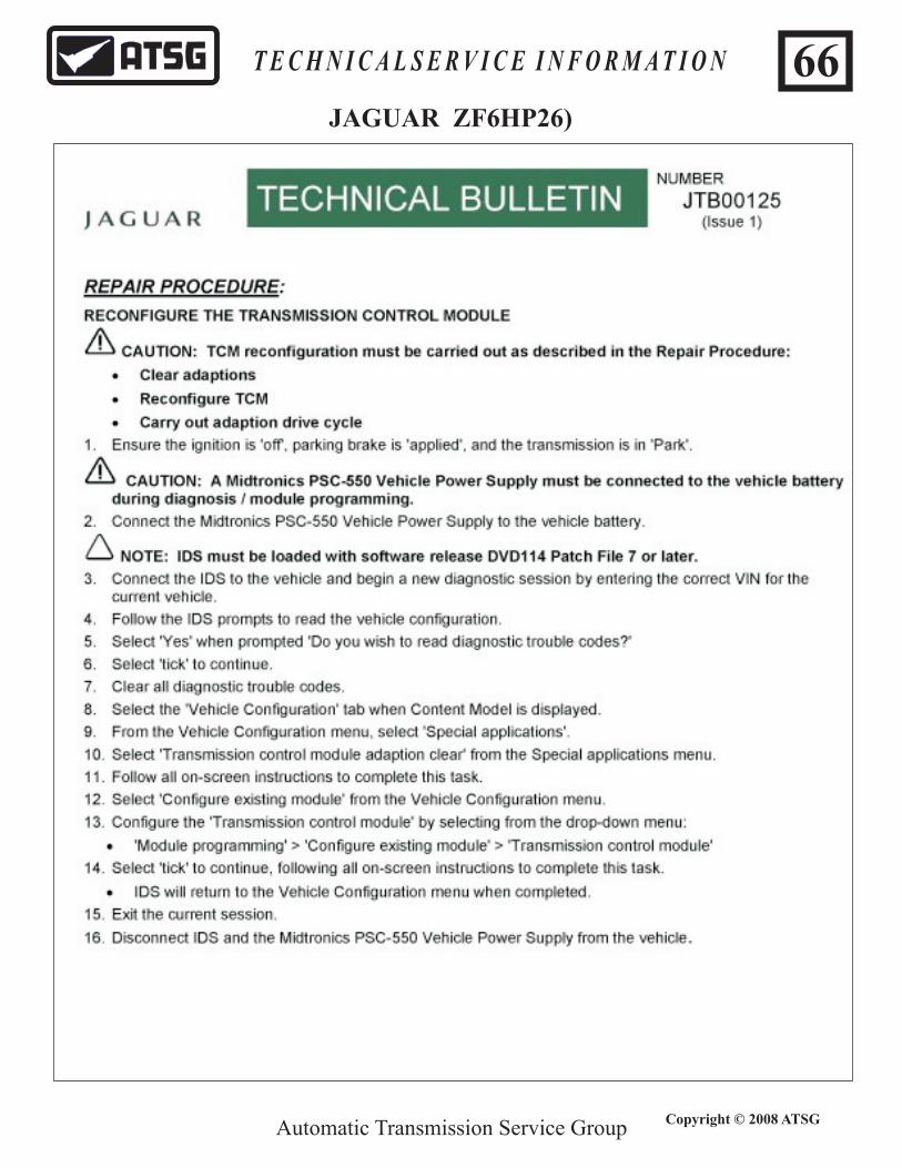
Automatic Transmission Service Group
T E C H N I C A L S E R V I C E I N F O R M A T I O N
Copyright © 2008 ATSG
66JAGUAR ZF6HP26)

Automatic Transmission Service Group
T E C H N I C A L S E R V I C E I N F O R M A T I O N
Copyright © 2008 ATSG
67JAGUAR ZF6HP26)

Automatic Transmission Service Group
T E C H N I C A L S E R V I C E I N F O R M A T I O N
Copyright © 2008 ATSG
68JAGUAR ZF6HP26)

Automatic Transmission Service Group
T E C H N I C A L S E R V I C E I N F O R M A T I O N
Copyright © 2008 ATSG
69JAGUAR ZF6HP26)

Automatic Transmission Service Group
T E C H N I C A L S E R V I C E I N F O R M A T I O N
Copyright © 2008 ATSG
70JAGUAR ZF6HP26)
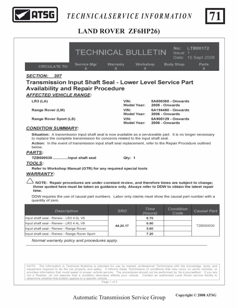
Automatic Transmission Service Group
T E C H N I C A L S E R V I C E I N F O R M A T I O N
Copyright © 2008 ATSG
71LAND ROVER ZF6HP26)