Embed Size (px)
Citation preview

REPAIR, EVALUATION, MAINTENANCE, ANDREHABILITATION RESEARCH PROGRAM
* * TECHNICAL REPORT REMR-GT-3
GEOTECHNICAL ASPECTS OF ROCK EROSIONIN EMERGENCY SPILLWAY CHANNELS
Report 3
REMEDIATIONI by
Christopher P. Cameron, David M. Patrick
CV (,Department of Geology, University of Southern Mississippi
SHattiesburg, Mississippi 39406-5044
S, -and
Craig 0. Bartholomew, Allen W. Hatheway._ . Department of Geological Engineering
University of Missouri, Rolla, Missouri 65401-6540
and
James H. May
Geotechnical Laboratory
DEPARTMENT OF THE ARMYWaterways Experiment Station, Corps of Engineers
PO Box 631, Vicksburg, Mississippi 39181-0631
JJN 3 1196
September 1988
Report 3 of a Series
Approved For Public Release; Distribution Unlimited
Prepared for DEPARTMENT OF THE ARMY
ARCH US Army Corps of EngineersWashington, DC 20314-1000
Under Civil Works Work Unit 32317891 30 096

The following two letters used as part of the number designating technical reports of reseaiJ1 publis•hed under the Repair,Evaluation. Maintenance. and Rehabilitation tREMR) Research Program identify the problem area under which the reportwas prepared.
Problem Area Problem Area
CS Concrete and Steel Structures EM Electrical and Mechanical
GT Geotechnical El Environmental Impacts
HY Hydraulics OM Operations Management
CO Coastal
Destroy this report when no longer needed. Do not returnit to the originator.
The findings in this report are not to be construed as an official
Department of the Army position unless so designatedby other authorized documents.
The contents of this report are not to be used for
advertising. punication. or promotional purposes.Citation of tradle names does not Constitute an
official endorsement or approval of the use of such
commercial products.
COVEHl PHOTOS
TOP R,)'k protec(tjon structulre ih emergency sp!llway channelat Black Butte Reservoir (California;
MIDDLE -. Sullway iischarge shortly before weir failure at DMAD
Resevoir (Utah)
BOTTOM - Rsjlts of erosion in errierqency spillway channel at)aylorvilfl Reservoir flowat

UnclassifiedSECURITY CCZASWII`CATION Or TFH S PAGE~
REPORT DOCUMENTATION PAGE OMBn lppo. 70.0FO
la REPORT SECURiTY CL-ASS!F.CATiON lb RESTRICTIVE %MARK!NGS
2a SECURITY CLASSIFICATION AUTIHORITr 3 DSTR'Bu ION; AVAILABILITY OF REPORTApproved for public release; distribution
2b DECLASSIFICATION]/ DOWNGRADING SCHEDULE unlimited.
4 PERI-ORMING ORGANIZATION REPORT NUMBER(S) 5 MONITORING ORGANIZATION REPORT NUMBER(S)
6a NAME OF PERFORMING ORGANIZATION 6b OFFICE SYMBOL 7a NAME OF MONITOR!NG ORGANIZATION
(See reverse) (If pcbe6c. ADDRESS (City, State, arid ZIP Code) 7b ADDRESS (City. State. and ZIP Code)
(See reverse)
8a NAME OF FUNDING/ SPONSORING 8b OFF'CE SYMBOL 9 PROCuREMENT INSTRUMENT IDENTIPICATIOIN NUMBERORGANIZATION (if applicable)
US Army Corps of Engineers 1Bc ADDRESS (City, State, and ZIP Code) 10 SOURCE OF FUNDING NUMBERS
ELEMENT NO NO. NO ACCESSION NO
Washingtun, DC 20314-1000 I 3231711 TITLE (Include Security Claussification)
Geotechnical Aspects of Rock Erosion in Emergency s)piilway Channels; Report 3: RcineLd i,1L i on
12 PERSONAL AUTHOR(S) (See reverse)
13a TYPE OF REPORT--- 13b TIME COVERED 174 DATE OF REPORT (Year, Month, Day) 15 PAGE COUNTReport 3 of a ere3 F R 0NA~iýj9 8 7 TCSP19871 September 1988
16 SUPPLEMENTARY NOTATION
(See reverse)
17 COSATI COD)ES 18 SuBJECT TERMS (Continue on reverse if necessary and identify by block number)FIELD GROUP SUB-GROIJP Cement-based materials Rock mass
Erosion SpillwaysHydraulic structures
19 ABS TPACT (Contmnue on reverse if necessary andJ identify by block number)
RL1AR research at the US Army Engineer torterwa 'vs Experiment Station has establishedtfA;it rorned st ion of Un ined emergency spililway erosion damage is a relatively new, butmajor , concern tIo Lthe US'Army Corps of Engineers (CE) bIistricts and to other dam owners andolmeraLors. The REMR wrrk unit conducting the current investigation has Identified numerousCE and IlLiler FeOderal, institutional, and private-.sector dams that have experienced erosiondainitl;e in thmeir unlined spillway chaninels. However, only a few Iprojects have implementedor 1 rndreinedial and/or prevent ive tseaisuros.
!Hesiidiuatioan (esiýýn Is highly site-s~pecific and must be Cost-effectiVe, address pub~lcand( provide continuied resecrvoir operations. Select!on of remedial technique(s)
inlist h~e esrtab) ishe:d by si to-spell1 fir characLerh'.ot ion of the rocks forming an unl Ined
(cont inued)10) 0'STF I UI JIJ 11Qj !A/A ILA GI3LI I" lOt AaSII1AC. 1 1 ABSTRACT SECUJRITY CLASSIFICATION
El '.IGASFL~ M, - U i SAM AS vp l ' US inc I ssif Ied
22a.. TAME OF RESPQI~jSISI E IFDIVIOUAL 2 2h TEL-EPHiONE (lnrlude Area Code) 122c OF/ICE SYMBOL
DD Form 1473, JUN 86 Previous editions aeobsolete ',ECaRiTY CLASSIFICATION OF THIS PAGE
Unc lascs if ied

Unclassified89CURITY CLASSIFICATION OP TNHI 1AGE
6a. NAME OF PERFORMING ORGANIZATION (Continued).
Department of Geology
Department of Geological Engineering
USAEWESGeotechnical Laboratory
6c. ADDRESS (Continued).
Uni, vrsity of Southern Miassissippidt La~ tu•U/g, '~i '~ ss i 39406-5044
UuijvtLrs.-ity: of Missouri, RollnRoll a, Missouri 65401-65410
PO Box 631
Vicksburg, MS 39181-0631
12. PERSONAL AUTHOR(S)
coo rolihrist opher P.; Patrick, David M; Bartholomew, Craig 0.; Hatheway, Allen W.;May, lames Ii.
16. SUPPLEMENTARY NOTATION (Continued).
A report of the geotechnical problem area of the Repair, Evaluation, Maintenance, andRehabilitation (REMR) Research Program. Available from National Technical InformationService, 5285 Port Royal Road, Springfield, VA 22161.
19. ABSTRACT (Continued).
.spillway channel In terms of rock composition(s), hardness, structural and stratigraphicdiscontinuities, and precursor erosion elements, all of which determine rock erodibilityand its rate. Erosion probability indices based on methods which combine rock mass param-eters (compsition, hardness, structural discontinuity, etc.), which determine "rippabil-ity," with lithostratigraphic continuity may allow for site-prioritization in terms of theneed for remedial and preventive techniques.
Potentially utcful remedial engineerIng-techniques include cement-based methods suchas grouting, shotcrete, soil cement/roll crete, and high-strength unreinforced and rein-forced concrete, as well as rock bolts, wire mesh, gabions, and riprap. Potentially use-ful erosion preventive measures include construction of energy dissipators and cut-offwalls and the removal of vegetation and other obstacles to flow. Flow rerouting, therelief of uplift pressures, and theC'placement of geotextiles and natural grasses (espe-cially in poorly lithified rocks and soils) may also offer useful alternatives. Themajority of these remedial techniques have been utilized previously in various erosionprotection schemes (e.g., stream banks, canals, levees, etc.); however, their use inunlined emergency spillway channels has not been extensive and there is little documenta-tion available. The selection of a particular remýelial technique will depend upon siteconditions and costs which are highly variable for a given method.
The present study established a need for more published documentation of performanceand effectiveness of remedial measures as well as efforts to predict rock erosion in emer-gency spillway channels by the use of erosional indices.
.Vnc la-s I fdSECURITY CLASSIPICATION OF THIS PAGE

PREFACE
This study addresses rock erosion in emergency spillway channels, a
problem area of the Repair, Evaluation, Maintenance, and Rehabilitation (REMR)
Research Program being conducted by the US Army Engineer Waterways Experiment
Station (WES).
This third report of a series summarizes work performed during FY 87.
Results of work currently in progress and ongoing research programs will be
the topic of further reports to be completed during FY 88 and FY 89. This
study was under the direct supervision of Messrs. J. S. Huie, the Problem Area
Leader, and D)r. J. It. May, the Principal Investigator, Engineering Geology and
Rock Mechanics Division (EGRMD), Geotechnical Laboratory (GL). General super-
vision was provided by Drs. L. M. Smith, Chief, Engineering Geology Applica-
tions Group, EGRnMD; D. C. Banks, Chief, EGRMD; and W. F. Marcuson III, Chief,
GL, WES.
Mr. James E. Crews and Dr. Tony C. Liu served on the Overview Committee;
Mr. Ben Kelly was the REMR Technical Monitor at Headquarters, US Army Corps of
Engineers. Mr. William F. McCleese, Concrete Technology Division, Structures
Laboratory, WES, was the REMR Program Manager.
This report was written by Drs. C. P. Cameron and D. M. Patrick, Depart-
ment of Geology, University of Southern Mississippi, Hattiesburg; Mr. C. 0.
Bartholomew and Dr. A. W. Hatheway, Department of Geological Engineering, Uni-
versity of Missouri, Rolla; and Dr. J. It. May, EGRMI), WES. The report was
edited by Mrs. Joyce Ii. Walker, Information Products Division, Information
Technology Laboratory, WES. The helpful comments and contributions of District
hydraulic -iind geotechnical engineers as well as those from individuals in the
privaLtc sector are appreciated by WES.
COL Dwayne G. Lee, EN, was Commander and Director of WES. Dr. Robert W.
Whalin was Technical Director.
i For
y .-
• -' ,. I :II

CONTENTS
Page
PREFACE ............................................................... 1
CONVERSION FACTORS, NON-SI TO SI (METRIC)UNITS OF MEASUREMENT .............................................. . 3
PART I: INTRODUCTION ................................................... 4Background .......................................................... 4Objectives ...................................................... 4Scope .............................................................. 5
PART II: PREDICTION AND REMEDIATION ................................ 6Overview ........................................................ 6Erosion Prediction .................................................. 8Erosion Probability Index .......................................... 11
PART III: REMEDIATION METHODS ........................................ 15Objectives of Remediation .......................................... 15Factors of Safety ..................... .............................. 16RemediJl and Preventive Measures ................................ 17
PART IV: CONCLUSIONS AND RECOMMENDATIONS ............................ 58Conclusions ......................................................... 58Recommendations ..................................................... 60
REFERENCES .... .. ....................................................... 61
2~
CONVERSION FACTORS, NON-SI TO SI (METRIC)UNITS OF MEASUREMENT
Non-SI units of measurement used in this report can be converted to SI(metric) units as follows:
Multiply By To Obtain
acres 4,046.873 square metres
acre-feet 1,233.489 cubic metres
cubic feet 0.02831685 cubic metres
cubic yards 0.7645549 cubic metres
degrees (angle) 0.01745329 radians
feet 0.3048 metres
inches 2.54 centimetres
p1-unds (force) per square inch 6.894757 kilopascals
square feet 0.09290304 square metres
square yards 0.8361274 square metres
tons (2,000 pounds mass) 907.1847 kilograms
3

GEOTECHNICAL ASPECTS OF ROCK EROSION
IN EMERGENCY SPILLWAY CHANNELS
REMEDIATION
PART I: INTRODUCTION
Background
I. Prediction of initiation, rate, and intensity of erosion in earth
materials is not a precise science, and a significant amount of erosion-
induced damage has occurred in unlined emergency spillway channels at flood-
control and water-storage projects buiit and managed by the US Army Corps of
Engineers (CE), other Federal agencies, state, and local interests. The
potential exists for severe erosion of the rock and associated soils flooring
of unlined emergency spillways to cause undermining or failure of spillway
structures and catastrophic release of reservoir waters, damage to dam embank-
ments, spillway channel bank failure, and sedimentation in the spillway exit
and main chb.nnel. Theretore, the CE was prompted to include this problem as a
work unit in the Repair, Evaluation, Maintenance, and Rehabilitation (REMR)
Research Program being conducted by the US Army Engineer Waterways Experiment
Station (WES).
Objectives
2. The objectives of this work unit include the following:
a. To identify and document the geotechnical and hydraulic factorsinfluencing the rate and mechanism of erosion in unlined emer-gency spillway channels.
b. To identify and document channel response to emergency spillwayflow and to assess the nature, magnitude, and severity of down-stream Impacts.
c. To develop methods of predicting erosion in unlined emergencyspillway channels.
d. To develop cost-effective remedial aind preventive measures tominimize the problem of severe erosion In unlined emergencyspil]way channels.
4
e. To maintain and continually update an observational data basewhich documents important erosive spillway overflow events at CEprojects.
f. To provide timely tcc[,nology transfer in this problem area to CEpersonnel and other interested parties in Federal, state, andlocal agencies.
Scope
3. Geotechnical factors control the selection of appropriate cost-
effective remedial and preventive engineering techniques capable of minimizing
existing and potential spillway channel erosion, maintaining the integrity of
spillway structures, and reducing downstream impacts. This report is primar-
ily dedicated to addressing remediation of erosion in rock; however, selected
remediation measures for soils and overburden are also presented since these
unlithified materials are usually closely associated with rock in emergency
spillway channels. This report, the third in a series, provides documentation
and assessment of remedial measures implemented (or contemplated) to solve or
impede erosion in emergency spillway channels. The combined results of
research conducted during FY 86 provide the rationale for proposing new meth-
ods of predicting erosion in unlined emergency spillway channels.
4. These reports are intended to serve as a mechanism for communicat-
inr research results. ideas, and concepts to interested CE personnel and their
counterparts in other Federal, state, and local agencies. CE District experi-
ence, case histories, and site visits, as well as technical input from other
concerned agencies, continue to provide vital elements of the working observa-
tional data base and serve as tbe IoundaLior for development and refining of
rese.irch tasks.

PART 11: PREDICTION AND REMEDIATION
Overview
5. Selection of an appropriate, cost-effective remedial technique at an
emergency spillway involves a number of alternatives. Remedial action options
range from a "do nothing" alternative, to expensive blankets of reinforced
concrete covering the entire spillway discharge channel. Choosing the most
appropriate combination of technologies for a given spillway is further com-
plicated by hydraulic design variables, geotechnical conditions, public
safety, downstream impacts, and the importance and present use of the
reservoir.
6. Emergency spillways are designed to protect the main embankment dur-
ing peak flood conditions. Spillway failure can lead to catastrophic loss of
reservoir waters. At many locations, loss of stored water would not have pre-
sented a serious problem at the time of construction. However, urbanization
has occurred downstream of many dam sites, and many reservoirs have become a
major source of water, hydroelectric power, and income through recreational
use. Loss of storage may result in loss of life at some locations, destruc-
tion of property, water shortages, and loss of revenue.
7. Remediation design is therefore highly site-specific and must be
cost-effective, address public safety, and provide continued reservoir opera-
cions. Optimal remediation design will provide, in some way, for all of the
design variables weighted against site-specific factors and conditions. If
this is not accomplished and remediation is performed strictly on the basis of
nasL pruieut experience or with excessive factors of safety, then either money
will be wasted or safety will be compromised. A tailor-made remedial plan
should not only save money, but provide a high degree of safety and
performance.
8. To create this tailor-made plan, the engineers and geologists
involved in remediation work must obtain all of the site and areal geologic
information, determine geotechnical conditions, consider the hydrologic set-
ting and the hydraulic characteristics of the structure and discharge channel,
and consider the implications Gf the interrelationship of each set of these
characteristics. Along with this, the remedial team (composed of hydraulic,
civil, an(d geolo;Iczi enginoers ;i, well as geologists) must consider
6

downstream impacts and reselvoir use. After assessing all of these elements
and the implications of their interrelationship, then an appropriate cost-
effective remedial plan can be formulated.
9. One important option in emergency spillway remediation that is not
available ii, •nost other engineering projects is that the remedial structure or
structures need not always be permanent. "There are situations due to rarity
of major events or other site-specific conditions where it may be justified to
construct a remedial structure that will be destroyed by that major event.
Such a situation presents itself when several of these lesser structures can
be constructed and reconstructed for the cost of one structure that will with-
stand the major event without damage to the dam or reservoir" (California
Department of Natural Resources 1974).
10. An example of this type of situation occurred at the Bridgeport Dam
in California, where hydrologic investigations showed that the emergency
spillway needed to be enlarged--a responsibility of the Walker River Irriga-
tion District (California Department of Natural Res'irces 1974). The major
problem in enlarging the emergency spillway was the fact that it was con-
structed in highly erodible glacial till, and that it was unlined. "Low-cost
concrete sills were installed to provide erosion protection" (California
Department of Natural Resources 1974). These structures were justified even
though they would be substantially damaged during a flow event and thus
require repair; however, they would retard the rate of channel erosion and
protect the main embankment. This measure was further justified by the fact
that the structures could be repaired or replaced several times with the cost
being substantially less than it would be for completely lining the spillway
with concrete. Options like the "impermanent structure" must be considered
when designing a remedial plan for an emergency spillway.
11. Another important consideration during emergency spillway remedia-
tion is the fact that all remedial structures must withstand a number of dif-
ferent forces. Many of these structures will be able to withstand the direct
torces of erosion but unable to withstand indirect forces such as undercut-
ting. Therefore, when considering remedial options for emergency spillways,
il I 1 thu possible effects of erosion must be addressed.
12. For large projects, which includes most of the CE dams, it may be
very expensive to employ preventive or remedial measures. Due to this fact,
-cale ind/or nuimerlcal models might be considered to assist in determining the
7

effects of employment of various measures. Proper use of such models can
create a great cost savings as well as providing a data base for more effec-
tive employment of engineering techniques. However, it should be remembered
that model studies cannot be effectively undertaken until after thorough
hydrologic, hydraulic, and geotechnical characterizations have been performed.
The models should be designed not only to reflect siLe hydrologic and hydrau-
lic characteristics but should also be designed in such a way as to adequately
represent the geotechnical and geologic properties of the site.
13. Many effective model studies have been carried out at WES. One
such study dealt with a scale model (Murphy and Cummins 1965). This study was
performed to determine the different effects of various remedial technologies
on arresting the erosion that had occurred downstream of the spillway at
Miraflores Dam in Panama. By employing a model study, it was determined "that
adequate protection would be provided by addition of a stilling basin consist-
ing of a 40-ft-long* apron terminated by a 3-ft-high dentated end sill"
(Murphy and Cummins 1965).
14. The major advantage of a model study comes from the fact that many
different combinations can be tried for a relatively small expense, especially
if numerical models are being used.
Erosion Prediction
15. Because the CE manages too many projects for each to be evaluated
individually, Cameron et al. (1986) recommended development of potential meth-
ods and techniques which could be used at District levels to force-rank or
prioritize unlined cmergency spillway channels in terms of their erodibility.
Using such methods, problem sites could be identified early and treated
promptly. The same authors proposed that the rock-mass parameters that govern
rippability, when combined with lithostratigraphic continuity factors, may
provide predictive erosion indices from a geotechnical point of view.
16. Rippability is a form of rock-mass classification, or rating, that
enhinces engineering judgment with respect to the assessment of the excavation
clharacteristfcs ,,f earth materials and bulldozer or backhoe ripping capability
A table (,t factors for converting non--5I units of measurement to SI (met-r c) un1 it ts I) preseInte(2d on page 3.
S... . . . . . . . . . . .. . . . . . __ . . . . . .. . .. .. . . . . .
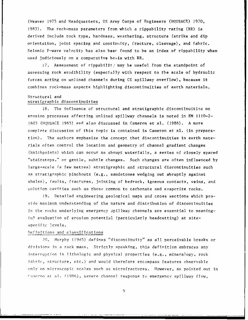
(Weaver 1975 and Headquarters, US Army Corps of Engineers (HOUSACE) 1970,
1983). The rock-mass parameters from which a rippability rating (RR) is
derived include rock type, hardness, weathering, structure (strike and dip
orientation, joint spacing and continuity, fracture, cleavage), and fabric.
Seismic P-wave velocity has also beer found to be an index of rippability when
used Judiciously on a comparative basis with RR.
17. Assessment of rippabilit., may be useful from the standpoint of
assessing rock erodibility (especially with respect to the scale of hydraulic
forces acting on unlined channels during CE spillway overflow), because it
combines rock-mass aspects highlighting discontinuities of earth materials.
Structural andstratigraphic discontinuities
18. The Influence of structural and stratigraphic discontinuiti'es on
erosion processes affecting unlined spillway channels is noted in EM 1110-2-
1603 (HQUSACE 1965) and also discussed in Cameron et al. (1986). A more
complete discussion of this topic is contained in Cameron et al. (in prepara-
tion). The authors emphasize the concept that discontinuities in earth mate-
rials often control the location and geometry of channel gradient changes
(knickpoints) which can occur as abrupt waterfalls, a series of closely spaced"stairsteps," or gentle, subtle changes. Such changes are often influenced by
large-scale (a few metres) stratigraphic and structural discontinuities such
as stratigraphic pinchouts (e.g., sandstones wedging out abruptly against
shales), faults, fractures, jointing of bedrock, igneous contacts, veins, and
solution cavities such as those common to carbonate and evaporite rocks.
19. Detailed engineering geological maps and cross sections which pro-
vide maximum understanding of the nature and distribution of discontinuities
In the rocks underlying emergency spillway channels are essential to meaning-
ful evaluation of erosion potential (particularly headcutting) at site-
specific levels.
)efinitions and classifications
20. Murphy (1985) defines "discontinuity" as all perceivable breaks or
divlsions in a rock mass. Strictly speaking, this definition embraces any
interruption in lithologic and physical properties (e.g., mineralogy, rock
fabric, structure, etc.) and would therefore encompass features observable
only on microscopic scales such as microfractures. However, as pointed out in
(•>neqron et al. (1986), severe channel response to emergency spillway flow,
9

particularly in CE spillway channel;, appears to be goveraed more by discon-
tinuities which occur on a megascopic scale rather than on a microscopic or
grain-to-grain basis. To maintain consistency in usage, definitions of
specific types of discontinuities discussed in the following sections are
those given in Glossary of Geology, (American Geological Institute 1987).
21. It is possible to classify discontinuities under two broad
headings--structural and stratigraphic. Structural discontinuities can occur
in all rock associations and are caused by movements resulting from natural
compressive and t:.nsile stress fields which affect rock masses in the upper
crust of the earth. The resulting rock deformation produces folds, fractures,
faults, joints, and, in the case of some orogenic belts, regional metamorphism
and the forceful injection of molten rock and other fluids. Depending on the
rock associations involved at a given crustal level, these processes can
result in variable orientations of such planar structural elements as stratal
dip, schistosity, foliation, formation of igneous contact zones, and veins,
all of which have significance as important structural discontinuities from an
eng•ineering point of view.
22. Stratigraphic discontinuities are usually lintwted to stratified
rock sequences (sedimentary rocks) including those hosting or admixed with
volcanic igneous rocks (lavas, tuffs, volcanic breccias, and volcano-clastic
sedimentary rocks). Stratigraphic discontinuities include depositional fea-
tures such as bedding planes, bed contacts, unconformities, sedimentary struc-
tures and textures as well as bed pinchouts and tacies changes within the same
lithostratigraphic unit.
23. Dissolution pits, cracks, and cavities result from chemical weath-
ering and erosion and comprise a special type of discontinuity. Although most
common in carbonates (limestones and dolomites) and evaporites (gypsum, anhy-
drite, salt, etc.), dissolution features can also occur occasionally in other
rock associations as well.
24. Faults and rap.id changes in dip orientation (tight folding),
stratigraphic pinchouts, rapid facies changes, and unconformities are of con-
siderable importance when present in an unlined spillway channel in that these
features often juxtapose rocks of widely varying competence and resistance to
eosion. For example, at Grapevine Spillway (near Dallas in the CE Fort Worth
Dilstrlct, "leyas) the pinchout of a moderately bedded sandstone unit controlled
the location of a channel gradient change (knickpoint). The steepened
10
dounstream reach, being underlain by soft, weathered, erodible shales, reacted
negatively to the first spillway flow event in 1983. Rapid undercutting of
the shale substrate resulted in collapse of the sandstone layer and headward
retreat of the knickpoint. A large stilling basin was constructed at a cost
of $10 million to Inhibit further headcutting during emergency spillway over-
flow. Other cases are cited in Cameron et al. (1986).
25. Lithostratigraphic continuity is a key factor controlling the rate
and intensity of spillway erosion in stratified rock sequences. Rapid changes
in lithostratigraphic facies, both laterally and vertically, appear to control
the location and rate of headward retreat of knickpoints and waterfalls and
locally ::aximizing hydraulic energies and scour intensity. Cameron et al.
(in preparation) discuss controls of lithostratigraphic continuity and propose
that modern methods of facies analysis allows for intelligent estimates of
facies variability and lithostratigraphic continuity on both regional and
local scales.
26. If structural and stratigraphic discontinuities are to be used
effectively in the evaluation and prediction of bedrock erodibility in unlined
emergency spillway channels, then rigorous attempts must be made to accurately
describe a',id quantify the features discussed above. Comprehensive methods for
describing and quantifying the rock mass features described above are given in
Murphy (1985).
Erosion Probability Index
27. The idea that an "Erosion Probability Index" (EPI) can be generated
for a given unlined emergency spillway channel is based on the concept that
the key geotechnical factors controlling erosion during spillway flow are con-
tained In rock-mass rippability and lithostratigraphic continuity and that
these factors can be quantified or assessed in a semiquantitative manner.
Assuming that the methods and techniques used to assess rock-mass rippability
and lithostratigraphic continuity are applied uniformly and consistently in
spillway channel evaluations, it should be possible to force-rank spillway
JAiannels in a given District based on their EI'1 values. This approach will
a~sisL estailishilng priorietIs for channel remediation, at least from the geo-
technical standpoint.
11

28. The major assumptions which govern the application of this approach
are:
a. All weighting processes and probability estimate methods havelimitations.
b. There are no universal formulas. Detailed site-specific evalu-ations are prerequisite to the successful application of thismethod.
c. All CE unlined emergency spillway channels will undergo futureflow events. Lack of previous flow events should never be anupgrading factor in terms of geotechnical evaluation of bedrockerodibility.
d. Data are based on measured parameters. Judgmental interpreta-tions are based on empirical observations and experience. Dataand Judgmental interpretations are both valid and necessarycriteria in site-specific evaluations.
e. Uniform and consistent methods of spillway channel evaluationwill be applied within a given District. This assumptionrequires that the geotechnical data base for each spillwaychannel be complete and that data quality is uniform throughoutthe District.
f. Where facility safety is a real concern, conservative interpre-tations should prevail; particuJarly with respect to subsurfacecorrelations based on wide-spaced borehole control.
29. The proposed method for calculating a geotechnical EPI (EPI ) is
illustrated in Table 1. The rating values used are illustrative only; indi-
vidual Districts should attempt to establish their own rating changes and fac-.
tor weightings based on local experience as to which factors exert major
erosional controls. For example, rock weathering varies in character and
intensity as a function of both rock type and climate and may be expected to
be weighted differently over state, provincial, or national areas.
30. From the standpoint of rock erosion in unlined emergency spillway
channels, rock masses with low RR values are easily excavated by conventional
rlppers (tractor- and bulldozer-mounted narrow profile instruments), and are
also those expected to be relatively nonresistant to the high hydraulic
stresses prevailing during spillway overflow events. At the other end of the
spectrum, very high RR can imply that the rock can only be excavated by blast-
ing. Such rock masses are often highly resistant to erosion. For example,
the exposed, hard sandstone ledge which floors the upper portion of the
unlined channel at the Saylorville (Iowa) spillway still bears the elongate
scars of a futile attempt to rip and excavate the channel to uniform grade
during dam construction. When ripping proved impossible, a decision was made
12

Table 1
Geotechnical Erosion Probability Indices (EPI )
Rippability Parameters (E )
Parameter Rating*
Rock mass parameters
Rock hardness 0-10Rock weathering 1-15Joint spacing 5-30Joint continuity 0-5Joint separation 1-5Strike/dip 3-15
Seismic P-wave velocity 5-20
Total rating 15-100
Continuity Parameters (E )
Vertical continuity
(bed thickness) 5-15
Lateral continuity 5-25
EPI = E + Eg r c
E = rippability (sum of weighted rock mass parameter ratings and seismicwave velocity)
E = lithostratigraphic continuity (sum of vertical and lateral bed/rockcunit continuity ratings
* Illustrative purposes only.
13

to leave the sandstone in place as a flooring for the upper portion of the
unlined channel rather than go to the expense of a drill ar.d blast excavation
exercise. The resistant sandstone body proved to be relatively nonerodible
and impeded serious headcutting during the 1984 flow event (Cameron et al.
1986).
31. Seismic P-wave velocity should be used with caution in estimating
rippability. HQUSACE (1983) recommends that seismic wave velocity be used
with caution in estimating rippability--further stating "When data can be
obtained on the parameters required for use of the rock-mass rating or other
similar systems in rippability assessment, their use will supplemert an
assessment using only seismic data and rock type and should enhance overall
engineering judgment."
32. Hydraulic factors controlling erosion during emergency spillway
overflow were studied by the WES Hydraulics Laboratory. Both geotechnical
(EPIg) and hydraulic (EPIh) indices should be used in the final rankings ofgh
unlined spillway channels in a given District, for example;
EPI = EPI + EPIh
g1
14

PART III: REMEDIATION METHODS
Objectives of Remediation
33. Remediation efforts should be designed to minimize, reduce, or to
obviate spillway erosion while meeting the necessary primary hydraulic design
criteria for passage of flood waters. The primary determination as to how
much water must be accommodated during Probable Maximum Flood (PMF) is the
responsibility of the hydraulic engineer(s). Following this determination,
the spillway surface should be evaluated as to what remedial engineering mea-
sures will be required to maintain the spillway under PMF conditions, or por-
tions thereof.
34. PMF or Spillway Design Flood (SDF) estimates have little relation
to the ability of rocks and soils forming the floor of an unlined emergency
spillway channel to withstand the erosive impact(s) of spillway overflow. PMF
and SDF estimates are used in the hydraulic design of the spillway structure.
These hydraulic parameters do not consider the geotechnical aspects of the
unlined spillway channel, and, hence, have no bearing on its erodibility.
Case histories at CE and other projects provide ample proof that severe chan-
nel erosion can occur during the overflows which represent only small frac-
tions of the project PMF or SDF (Cameron et al. 1986). For example, overflow
representing 9 percent of design discharge caused severe erosion of the rocks
underlying the unlined portion ot the Saylorville, Iowa, spillway during June-
July 1984. Three overflows in the range 4 to 8 percent of design discharge
caused considerable erosion in the Lake Brownwood (Texas) spillway. The
21-day overflow during 1981 at the Grapevine (Texas) spillway reached only
5 percent of design discharge, yet produced severe, rapid headward erosion in
thu channel, and a rugged erosional landscape developed downstream with up to
30 ft of local relief.
35. Remediation techniques for unlined emergency spillways rely on the
ability of spillway channel earth materials to resist erosion. This must be
established by site-specific identification of material properties or charac-
teristics that would lead to erosion. This determination is followed by con-
sideration of remedial measures to strengthen the spillway material(s) at
points susceptible to erosion.
15

36, Suitable remedial methods can be devised for virtually every spill-
way, but most cases will retain an element of uncertainty as it relates to
the factor of safety and risk assessment in achieving remediate goals. The
uncertainty relates to characterization of site geotechnical factors as well
as the selection of design-related variables and t-' inadequate quantitative
prediction methods for rates of erosion or headward migration of erosion.
These factors, strength, abrasive resistance, and chemical stability of reme-
diated earth materials must be determined in terms of the hydraulic stresses
generated by spillway overflows.
Factors of Safety
37. An important goal in the selection and design of remediation should
be the computation of a factor of safety for the performance of each designed
remedial method. Factors of safety, considering strength alone, may be calcu-
lated for spillway slopes either with or without remediaton. The factor of
safety should also incorporate the additional remedial strength, abrasion
resistance, and chemical stability (sum of resisting forces) afforded by the
remediate method and which are opposed by the sum of the hydraulic (driving)
forces acting on the channel. However, uncertainty Is inherent in terms of
calculating both resisting and driving forces. The uncertainty derives from
our inability to calculate either theoretical or empirical values for the ero-
sion resistance of remedial measures due to the absence of a base of theoreti-
cal knowledge on erosion resistance and a lack of sufficient experience and
case histories pertaining to the success or failures of the various remedial
measures. Further uncertainty involves the calculation of the hydraulic driv-
ing forces acting on the channel. Current experience at CE dams indicates
that severe erosion has occurred at spillway discharges which were merely
fractions of the PMF (Cameron et al. 1986). Preliminary laboratory and addi-
tional field investigations have verified these occurrences of erosion at low
discharges and explained them in terms of spillway geometry and thresholds
(Cameron et al. keport 2 of this series (in preparation)). Thus, factors of
saietr Lor remediation cannot be calculated at this time.
16
Remedial and Preventive Measures
38. Measures are designated as remedial or preventive based only on the
time of application; that is, whether the measure used before or after the
spillway channel has been damaged.
39. Each of the measures to be discussed represents a technology, or
set of technologies, that are well proven in a variety of engineering applica-
tions. However, some of the remedial measures to be recommended herein have
not yet, at least within the knowledge of the present authors, been well docu-
mented for use in emergency spillways. Those technologies that are not well
ducuUL~ittd fur use in emergency spillways are measures which the authors
believe can provide viable and cost-effective alternatives at many emergency
spillway locations.
40. During the present study, the authors found a need for more pub-
lished documentation of the effectiveness of different remedial measures for
emergeiic) spiliu.&,. Alt_1iUL, the authors have conducted a thorough litera-
ture search and have consulted the CL data base, as well as those data bases
for other Federal dams, there is very little published information on remedial
engineering. Also, there is very little published information on state, pri-
vate, or local interest dams, even though we suspect that there may be a num-
ber of successful case histories for some of these dams, which have not been
formally published.
Reservoir reregulation
41. Reregulation should be considered as a temporary means of reducing
the potential for erosion of unlined emergency spillway channels. This simple
act entails lowering the reservoir, prior to the flood season, so that the
emergency spillway may either not experience flow or so that such flow may be
at velocities and heads less than those estimated to initiate erosion.
42. This approach is particularly appropriate whenever the emergency
spillway has been previously damaged by flood flows, has a significant poten-
tial for such damage, or is awaiting ýr undergoing remediation (e.g., Black
Butte Dam, California, Sacramento District). In all cases, reregulation is a
temporary (yearly) solution to a recurring problem. Reregulation cannot be
applied to dams at which the service and emergency spillways are one and the
same, or to dams that have been built without mechanical regulatory
•tructures.
17

43. Reregulation is often not an acceptable, long-term solution to a
real or perceived erosion problem at the emergency spillway. For those reser-
voirs that rerve as flood regulation facilities, this approach is conservative
to the degree that it provides additional reservoir storage capability and
therefore reduced potential for negative downstream impacts. For those reser-
voirs that also serve as irrigation storage, this form of protection may be
unacceptable, in that the protective, empty storage volume may not be replen-
ished by wet-season runoff, and the irrigation function may not be met. In
this case, the portion of the available reregulation storage may be limited to
the degree that irrigation demands may still be met on a low-precipitation
basis. Reregulation may also be unacceptable where the dam serves to maintain
a navigation pool or is primarily for hydropower poses.
44. Costs associated with adoption of reservoir reregulation are
entirely related to secondary impacts related in turn to the function of the
reservoir. Unlike costs associated with remedial engineering of emergency
spillways, these cannot be linked directly to specific unit, nor can such
costs be directly estimated. The actual costs of implementing reregulation
are contained in the normal operating budget of the reservoir, being mainly
associated with manpower required to monitor storage volumes and rates and to
operate control structures (Table 2).
Table 2
Cost Factors Related To Reregulation
Secondary Impacts Function of Reservoir
Crop loss Insufficient irrigation storage
Recreation inactivity Insufficient water to provide boat ramp access,boat movement, and access to fishing grounds
Erosion and siltation Water level reduced to elevations producing ero-sion and sedimentation within the reservoirbody (and upstream due to lowering of localbase level resulting in increased erosionalenergy in the watershed)
Loss of wildlife Nesting for aquatic birds and a reduction in liv-habitat ing space and spawning areas for fish and other
aquatic life forms
Hydropower and water Waaer levels reduced leaving insufficient head tosupply loss supply power and water
18

45. One example of reregulation occurred at the Brooktrails No. 3 North
Dam in Willits, California, where the reservoir is used for domestic water
supply (Redlinger et al. 1975). At this location an old landslide threatened
to block the spillway. One of the first immediate remedial measures was to
empty the reservoir--a type of reregulation. After the reservoir was empty,
permanent repair, consisting of a series of drains, was carried out.
Cement-based remediation
46. Concrete and various other portland cement-based pavings are tradi-
tional lining materials for a wide variety of spillway channel construction
and repair applications. In addition to its use os a reinforced lining blan-
ket, options such as lean concrete, shotcrete, high-strength mixtures, grout-
ing, dental concrete, acid rollcrete are available. One great advantage to
cement-based remediate techniques is that most of them tend to reduce or elim-
inate the possibility of rock plucking occurring within the emergency
spillways and their unlined channels. Due to its extensive technological
development, concrete is often the first and sometimes only measure considered
in construction and/or repair of emergency spillways and their unlined chan-
nels. There are many situations in which a concrete application will be the
best choice, both from the standpoint of cost and from hydrological and
geotechnical/geological characteristics. However, there will be many situa-
tions where these same factors create conditions which make concrete cost-
prohibitive or structurally inappropriate.
47. Most cement-based remediation techniques are those that are applied
by workers and/or machines directly to the area of the emergency spillway
requiring attention. An alternative use of cement-based materials is in
grouting, in which the cement-based material is delivered to a remote point or
place of application by borehole injection mainly along rock discontinuities.
Grouting
48. Grout is a cement- or chemical-based mixture generally placed in
voids and open discontinuities that cannot normally be reached by workers or
equipment. Portland cement grout is a traditional dam construction material
that is generally used to consolidate a mass of rock; whereas, chemical grout
is used as a primary med1os Of soil consolidation. Both will help in forming a
harrier to ground water flow. As applied to remediation of unlined emergency
sp51] way chaniil•i, cement-based grout would serve primarily to consolidate or
19

strengthen an entire rock mass. The consolidation takes place by grout fill-
ing the open voids or discontinuities, thereby removing treated discontinu-
ities as low-strength features susceptible to plucking or other forms of
erosion. A secondary advantage of grouting is that, when properly applied,
grout will strengthen the entire treated rock mass and provide an increase in
the overall strength of the rock mass. A tertiary advantage is that, once
consolidated, a grouted rock mass will likely not be subject to uplift forces,
possibly against even the maximum flood discharge that can be accommodated by
the spillway channel.
49. Grouting has an inherent problem in application to remediation of
emergency spillway channels. Grout injection requires pressurization of rock
intervals below the ground surface. Most spillway channel remediation needs
call for consolidation of the exposed and very near-surface (usually the
uppermost 3-4 m) spillway channel material and would involve procedures very
similar to consolidation grouting for foundations (Table 3).
Table 3
Conditions for Employment of Grouting
Applied to uppermost few metres of spillway surface.
Can serve as final flow-resistant surface where adjacent intact rock is
erosion-resistant.
I.ean concrete
50. Lean (low cement content) concrete is a low-cost void-filling mate-
rial f,'r -onditions where high structural, loads are not present. Most lean
concretes are mixed with fine sand aggregate and cement in sufficient quantity
to assure an easfly placeable viscosity and ease of movement into voids and
open discontinuities. Typical compressive strength of such lean mixtures
averages 10 to 20 MI'a (1,500 to 3,000 psi) for most applications.
51, The sole purpose of lean concrete should be to fill voids and open
discontinulties, and to prevent plucking, which will increase erosion resis-
tai(:ce. Typical remediation uses of lean concrete would be to fill open
structural discontinuities it, the channel bottom where the lean concrete
inIJllIng wil, be capped with erosion-resistant material . Even this
erosion-resistanit layer wil I L not requirct expensive, high-streingth concrete or
20

large-aggregate mixtures, as flood bedloads in emergency spillways are small,
due to clear water releases at the crest (Table 4).
Table 4
Conditions for Employment of Lean Concrete
Bulk filler not exposed to erosive forces.
Open-fracture filling.
Shotcrete
52. Shotcrete refers to a specific mixing and placement method for
pneumatically applied surficial mortar. Dry-mix mortar components (cement and
aggregate) are led to the application gun and mixed together with water prior
to being projected through a nozzle equipped with a perforated manifold. This
sprayed concrete can be placed with a low water-cement ratio, and therefore
can achieve a high compressive strength (Merritt 1968). The term gunite is
syrionlymous with shotcrete, but is not preferred as it stems from proprietary
sources. Shotcrete may also be applied as a wet-mix.
53. Design uses of shotcrete should be based on achievement of suffi-
cient compressive strength to represent erosion resistance and to serve in
whatever rock mass reinforcing role it has been assigned (Table 5).
Table 5
Conditions for Employment oi Shotcrete
Applied to expsed inclined surfaces.
Nut a primary hannel surface material.
Musit be protec ed from uplilt pressures.
Must not be applied over areas of variable compressive strength.
S -. ,_t Yr en ct n, ret e
V4. fligh-str,,tgt h, reinfo~rced or iinrefimlorcd, concrete relers to vari-
,,,r. ii. zt tires•o roltrrete that pro vide added abrasive re. ;i.;tamice and o:ompres-
,;iv- A-re:igth. ' Mhese miztumres may cuts .st of tie I,'.ic concrete mixture
V 1

with the addition of silica fume, a high-range water reducer, providing a
lower water/cement ratio and a hard aggregate.
55. High-strength concrete was placed in the stilling basin of the
Kinzua Dam (Pennsylvania) that had experienced "severe abrasion-erosion."
Silica-jume and limestone available near the site proved suitable and cost
effective (Holland et al. 1986). Repair concrete met a 28-day compressive
strength of 86 MPa (12,500 psi) and also had the required abrasion-erosion
resistance.
56. The result of a companion study (Holland 1983) showed that the
performnance of aggregates cannot be determined from the rock name or classifi-
cation. Samples with diabase and gabbro aggregate had the same erosion resis-
tance as a sample with limestone aggregate. "The answer to this apparent
anomaly lies in the difficulty of attempting to prejudge the performance of an
aggregate based upon a rock name. The resistance of an aggregate to abrasion-
erosion damage is apparently closely related to the hardness of the aggregate"
(Holland 1983). Hardness is not dependent upon rock name or classification.
It is dependent upon such factors as cement type, grain size and type, weath-
ering, etc.
57. Erosion resistant concretes made from silica fume and high-range
water-reducing admixtures (HRWRA) will perform as well as polymer con-
cretes (PC), polymer UCP portland-cement concretes (PPCC), and polymer-
impregnated concretes (PIC), and will be less expensive and easier to produce
and install (Holland 1983). However, "The use of a silica-fume concrete will
require careful control and inspection. The batch plant will have to be capa-
ble of handling the silica fume in whatever form It is made available by the
producer (slurry or dry). To achieve the full benefits of the silica fume, it
will, also be necessary to use a high-range water-reducing admixture (HRWRA)"
(Holland 1983), which is a polymer additive that increases workability and
particle contact (Elifrits 1987*). "The use of an HRWRA will raise the
problems normally associated with these products, particularly slump loss
versus travel time from the batch plant. Overall, it must be recognized that
i silica-fume concreLe is a sophisticated material that will require greater
tlhan norinai care and Inspection" (Holland 10)83). If time and financial
* Personal communication, 1987, C. 1. ElIfrits, Associate P'ro•essor of ;eo-logical El'gineering, tlniversity of Missouri, Rolla.
2?

constraints, or other site-specific conditions, do not allow for this greater
care and inspection, "It would be better to select a more conventional con-
crete for the repair material" (Holland 1983).
58. Silica-fume concrete is especially effective •n withstanding
abrasion-erosion. At most emergency spillways, overtopping of the spillway
structure involves a "clear water release"; i.e., waters entering the spillway
discharge channel do not contain a bedload or suspended load. Abrasion-
erosion of emergency spillway channels during a flow event is not likely to
occur except in the downstream portions of large channels. The use of silica-
fume concrete would only need to be considered for the downstream portions of
the emergency spillway channel and not fo'- other areas except in special cir-
cumstances. If the entire spillway channel is to be lined, thus removing the
source of abrasive material, it wculd be unnecessary to use silica-fume con-
crete in any portion of the spillway channel (Table 6).
Table 6
Conditions for Employment of High-Strength Concrete
A primarv meanc: of resisting erosion forces.
Reinforced or unreinforced.
Most expensive of concrete-based treatments when used over large areas.
Must consider deformation moduli of underlying geologic materials.
Must have drainage provisions to resist uplift pressures.
Soil cement and rollcrete
59. Cement has long been used as an additive to stabilize and
•tZreogthei soil and overburder to serve as a bearing substratum for roads and
airfields. Small percentages of cement are added and mixed with soil prior to
compa( io n. The technique has been extended over the past decade to use in
intifor dam embankments as rollcrete (roller-compacted concrete). This technol-
.. is ziuw ,I well-accepted innovation. One of the remediate measures consid-
C rId lor us.e on t Lhe emergency spillway at Sam Ravburn Dam, eas t Texas,
iIi'UilvL( a fU-cm (2A-in.) hlanket o1 rollcrete over the first 700 m (2,000 ft)
('I the ef [l.gency spill way channel. Ihis alternative would cost approximately
1h., million; however, some damage to the emergency spillwav would still occur
dur ili j ;I.ag1' (dI ilt, 'MI (Cainmeron et al. 106h) ('able 7).
21

Table 7
Conditions for Employment of Soil Cement/Rollcrete
Not generally considered for primary resistance to erosion.
Used to fill in relatively large voids.
Must have accessibility for placement.
Has relatively high shear strength and very low compressibility when placed inthick (say more than I m) bodies.
Employs cement 8 to 12 percent range, as an additive.
Applicability limited to soils/overburden and very weak rock.
Reinforced concrete
60. Reinforced concrete has been in use for a long time in hydraulic
structures. It is particularly used for constructing portions of concrete
gravity dams, spillway weirs, and also for the aprons below such weirs. Due
to the fact that this method involves the use of large amounts of reinforcing
steel, which must be installed prior to placement of the concrete, it is
qecond in expense to high-strength concrete. Due to the large size of most
emergency spillways at CE dams, it would be cost-prohibitive to consider using
reinforced concrete to line the entire spillway channel. One example of the
great expense that can be encountered when using reinforced concrete is at Sam
Rayburn D)am in east Texas. At this location, one of the proposed remedial
measures involves the placement of a 43-cm (18-in.) blanket of reinforced con-
crete over the first 700 m (2,000 ft) of the unlined emergency spillway chan-
nel at an estimated cost of $85 million. Even at this great expense, passage
of the PMF could still fail the spillway weir, while smaller "flows might
result in extensive damages to the channel" surface (Cameron et al. 1986).
Keeping this example in mind, it is recommended that reinforced concrete only
be considered for use in small portions of the spillway channel.
61. Another factor which must be kept in mind when considering rein-
forced concrete in remediation is that it is only effective as long as the
flow passes over the top. If flood waters are able to flow beneath a
reintorced-concrete section, failure will possibly occur due to the removal of
the subgrade material by floodwaters. A similar type of failure can occur at
the outlet portions of an emergency spillway when steep slopes or cliffs exist
24
below a reinforced-concrete section. This type of failure occurs due to tur-
bulence at the bottom of a steep channel section causing undercutting
(Table 8).
Table 8
Conditions for Employment of Reinforced Concrete
As primary resistance to erosion.
Often proves to be very expensive.
Can be used to span bodies of earth materials having a wide range of deforma-tion moduli.
Offers highest assurance of erosion resistance, under conditions of properplacement.
May be susceptible to undercutting erosion.
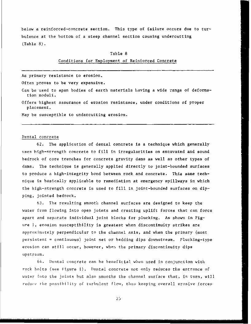
Dental concrete
62. The application of dental concrete is a technique which generally
uses hIgh-strength concrete to fill in irregularities on excavated and sound
bedrock of core trenches for concrete gravity dams as well as other types of
dams. The technique is generally applied directly to joint-bounded surfaces
to produce a high-integrity bond between rock and concrete. This same tech-
nique is basically applicable to remediation at emergency spillways in which
the high-strength concrete is used to fill in joint-bounded surfaces on dip-
ping, jointed bedrock.
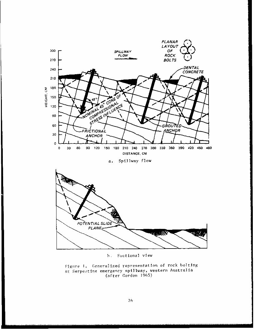
63. The resulting smoothi channel surfaces are designed to keep the
water from flowing into open joints and creating uplift forces that can force
apart and separate individual joint blocks for plucking. As shown in Fig-
ure 1, erosion susceptibility is greatest when discontinuity strikes are
approximately perpendicular to the channel axis, and when the primary (most
persistent = continuous) joint set or bedding dips downstream. Plucking-type
erosion can still occur, however, when the primary discontinuity dips
upstream.
64. Dental concrete can be beneficial when used in conjunction with
rock bolts (see Figure 1). Dental concrete not only reduces the entrance of
water into the joinlts but also smooths the channel surface that, in turn, will
red:•e t:he possbil1ity of turbulent flow, thu;; keeping overall erosive forces
25
PLANAR /LAYOUT
300 SPILLWAY OFFLOW ROCK
270 BOLTS
240 DENTALCONCRETE
210
; 180I-
:2 150
- 120
90 G
60 s' GRO
FRICTIONA LANCHO30 ANCHOR
0 _ .L ._._L
0 30 60 90 120 150 180 210 240 270 300 330 360 390 420 450 480
DISTANCE, CM
a. Spillway flow
S~POTENTIAL SLIDE
PLAN
b. 8Ictional view
Flgtire 1. Ceneralized representation of rock bolting
at Serpeitine emergency spillway, western Australia
(after Gordon 1965)
26
S. .. ... .. . ... .. . ..... .. . . . . .. i .. .. .. .. . . .. ... . .. .. ] .. .. . . .. . .. . .. . . .. .. . ... . . .. ..I .. . . .. .. . ..... .. .. .. . . .. . .. . . ...- -.... .. . .

to a minimum. Dental concrete should be applied as a continuous surface with-
out feathered edges. A minimum thickness of perhaps 20 cm should be consid-
ered as being capable of resisting erosion (Table 9).
Table 9
Conditions for Employment of Dental Concrete
Presence of open (approximately 10 mm or more) discontinuities and a signifi-cant degree (approximately 15 to 30 cm) of vertical microtopography betweenhigh and low areas of the rock surface.
Where discontinuity frequency is excessively high (i.e., of very close spac-ing; less than 15 to 30 cm), the ability of dental concrete to hold channel-suriace blocks to the spillway is probably minimal.
Competent, reasonably strong (> 5 MPa) rock at the channel surface, to createa concrete-rock bond capable of resisting uplift and plucking around rela-tively thin edges.
Costs of cement-based remediation
65. Costs of implementing concrete-based remediate measures are greatly
affected by site-specific conditions. Table 10 gives approximate cost ranges
for typical emergency spillway remediation conditions.
Rock boltiný
66. Rock reinforcement through rock bolting addresses two general con-
cepts, (1) consolidation of the rock mass or (2) application of sufficient
compressive force normal to failure-susceptible discontinuities to overcome
tendencies to slide (Figure 1a). Rock bolts represent a method of distribut-
ing COL,,pressive forces across discontinuity surfaces; either to resist sliding
(the must common application) or to bring individual discontinuity-bounded
rock-mass blocks closer together, so as to be in tight contact and to offer
resistance to uplift. Resistance to uplift, in a rock-bolted rock mass is
gained not only by friction between more tightly-contacting rock blocks, but
by the fact that discontinuities become largely closed to entry of water,
hence reducing the potential for uplift (IIQUSACE 1.978 and Bennett et al.
1985) .
67. Subhorizontal stress relief (exfoliation or sheet jointing) is
2specially adaptable to rock-bolt retention. Such a case was encountered at
Serpentine Dam, near Perth, western Australia. Sheet joints were there
27

Table 10
Approximate Costs of Cement-Based Remediation Methods
Technique Cost/Unit
Grouting* $1.50-150/m2 ($0.50-50/ft )
Lean concreteBulk filler not exposed to
erosive forces $30/m
Open-fracture filling $75-125/m 2
Shotcrete (Gunite)** Assuming coverage of 10 cm (4 in.) thick
Standard $20-40/m2 ($ 2-4/ft2)
Reinforced $60-90/m2 ($7.20/ft )
High strength concrete
Standard (unreinforced) $70/m2 ($2-4/ft )
Soil cement/rollcrete
Used as a blanket-type cover $10-25/m2 ($7-14/ft )
over selected (erosion-initiation) points in theemergency spillway channel
Reinforced concrete
A primary resistance to erosion $50-10/mr2 ($5-10/ft 2 )
Notes: All cost multipliers to convert from earlier years to present weremodified from Albritton, Jackson, and Bangert (1984); costs giveconsideration to the relatively smaller volumes of cement-based reme-dial methods than are normally applied with cement-based material onconstruction projects. The costs given above are approximations andare to be used in a relative sense.
* See Albritton et al. 1984.(1.6 1 1984 dollars = 1987 dollars)
** Sage (197?) (1974 prices / 3 = 1987 prices).
28

"subparallel to the natural rock surface," herein interpreted to outcrop along
one side of the channel and to strike about parallel to the channel axis, and
dipping, unfavorably, at 50 deg toward the channel (Gordon 1965). Rock bolt-
ing was considered (Figure ib) as a means of limiting the potential of a block
slide of jointed rock into the spillway channel.
68. A large variety of rock-bolt types and anchorage technologies are
available. Most of rock-bolt technology deals with the need to reinforce rel-
atively large masses of rock slopes. For emergency spillway applications, in
which most of the force-resistance requirements are to reduce or to counter
uplift and plucking, rock bolts need only be single-rod varieties of rela-
tively short length and held under only modest compression or by relatively
short lengths of borehole cementation (Tables 11 and 12).
Table 11
Conditions for Employment of Rock Bolts
Most effective when the spillway channel or channel walls contain a discontin-uity set that dips parallel or subparallel to the wall slope or channelfloor.
Least effective when dominant discontinuity set is vertical or when multiplesets are closely spaced (at spacings of less than approximately 60 cm).
Rock masses to be reinforced must be composed of material having a compressivestrength > 5 MPa.
For application in relatively small areas of the spillway or channel walls,especially at those areas/locations that appear to be particularly suscepti-ble to erosion or to initiation of erosion.
Commonly utilized in conjunction with grouting, dental concrete, and wire-meshblankets.
69. Yieldable rock bolts offer a means of resistance to surge-type
dynamic, hydraulic forces. Such force might be encountered in downstream
portions of some spillway channels subject to heavy debris flow (such as
timber and boulders), which could originate in steep forested terrane,
especially in weak-rock or tectonically active regions. Yieldable rock bolts
can be used to elastically react to dynamic impact from bedload passage simi-
lar to shock absorbers.
29

Table 12
Costs Related to Employment of Rock Bolts
Element Cos;t
Drilling
medium hard rock $ 9-13/mhard rock $12-20/m
Bolt $ 6-9/m
Installation to includeepoxy or grout $20-30 each
Wire mesh
70. Highly jointed rock masses approach a condition in which the spill-
way channel is composed essentially of rock blocks. Where weathering is not
extensive, it may be adequate to employ only a heavy, rock-bolt-anchored, wire
mesh stretched over the channelway. Wire mesh may be plastic-coated to pre-
vent corrosion. A double-twist mesh should be considered as a means of limit-
ing propagation of any local break. The mesh should be anchored by bolt
tension less than the tensile strength of the wire. Properly installed mesh
should effectively stop the scouring of blocks larget Wan the mesh openings,
essentially retaining the competence of the spillway channel surface.
71. Design considerations for mesh retention are: (a) appropriate
mesh-opening size which is smaller than the smallest blocks in the channel,
(b) proper anchorage in competent rock, and (c) the use of an upstream debris
barrier to eliminate ripping of the mesh by floating and suspended trees and
other debris.
72. The use of a mesh-blanketed channel to resist erosion is completely
dependent upon mesh continuity and anchorage. Debris, such as uprooted trees,
will cause the greatest damage to both mesh and anchorage. Ideally, trees and
logs should be cleared from emergency spillway channels. Where this is not
possible, an appropriate debris barrier must catch whatever are the typical
floating debris of the upstreali channel. Where a significant debris-
generation potential exists in the watershed, more than one barrier might be
required. For example, two or three nets suspended from buoyed cables could
be instaiLed as a series. However, under no circumstances should debris bar-
riers impede passage of spillway overflow. Only under special circumstances,
30

such as water drawn from below the surface of the reservoir, would considera-
tion of bedload debris be necessary.
73. A less common threat of mesh damage stems from rock brought down
from spillway channel reaches located upstream from the repaired section. In
most cases this rock should not result in ripping and widespread destruction
of the wire-mesh blanket. Even if one section of the mesh was damaged by
these rocks, it is probable that only a small area would be effected, and
repairs would be inexpensive (Tables 13 and 14).
Hydraulic energy dissipators
74. An energy dissipator is a concrete, gabion, or riprap (rock) struc-
ture so placed as to reduce the energy of impinging water. Such structures
act to reduce flow velocity or to turn the direction of flow without destruc-
tive erosion. A variety of sizes and shapes can be used for almost any
Table 13
Conditions for Employment of Wire Mesh
Where sections of the channel floor or sidewall are composed of rock blockswhich are too small to employ rock bolting techniques.
Rock blocks must be large enough not to pass through the mesh.
When rock block size varies to a large degree, mesh can be used in conjunctionwith rock bolts.
Corrosion resistance of wire must be included in design.
Table 14
Costs Related to Wire Mesh
Mesh Size Cost/Unit
Chain-link type
6 gage = 4.9mm (0.192 in.) $13-27/m2 ($l-$1.25/ft )
9 gage = 3.7mm (0.144 in.) $6-$21/m2 ($0.60-$0.84/ft2)11 gage = 2.9mm (0.116 in.) $4-$11/m 2 ($0.40-$0.60/ft2)
Triple-twist type
11 gage = 2.9mm (0.116 in.) $12/m2 ($0.50/ft2
Note: After Sage (1977) (1987 prices = 1975 price x 2.79).
31

location. Dissipators are constructed from concrete blocks, gabions, riprap,
or any other durable material that will effectively dissipate flow energy to
force levels su.all enough to preclude unacceptable erosion.
75. Energy dissipation is dependent upon disvipator size and location
in tI channel as well as distance from any other dissipators. Design of
energy dissipators is based on hydraulic theory and considers such parameters
as channel shape, discharge, tailwater elevation, and maximum expected flow
velocity.
76. Energy dissipators can effectively reduce the erosive force of any
given flow event. They may be effective by themselves in appropriately mini-
mizing the erosion potential, but, at many locations, it may be advisable to
use energy dissipators in conjunction with other measures to ensure the com-
petence of the reservoir, retention of the main embankment, and appropriate
reduction of downstream impacts (Table 15).
Table 15
Conditions for Employment of Energy Dissipators
SLeep channel gradients where turbulent flow is possible.
Provision for a suitable subgrade or anchor for the dissipation structures toensure their competence.
Appropriate hydraulic conditions particularly with respect to headwater andtailwater elevation(s).
Scale and numeric modelling is appropriate for large projects.
77. Stairstep energy dissipators are formed to slope backward, into the
upstream section of a spillway, creating numerous inclined surfaces that
dissipate flow energy as the water travels up each surface. In a situation
where the emergency spillway is excavated into tightly jointed, competent
bedrock, with weak or weathered rock in the channel below the spillway, it may
be very beneficial to construct the downstream portion of the spillway
structure as a tilted, stairstep structure. This would reduce the energy of
the water at the toe of the spillway and thus reduce the erosion by the flow
downstream.
78. This option could also be considered in cases where the emergency
spillway channel has a very steep outlet slope.
32

79. Costs related to eniergy dissipation will vary depending upon mate-
rials used (onsite, as compared with man-made or brought in), site conditions
(geologic materials and discontinuities present), what type of anchoring must
be applied, and location. Due to these factors no costs have been quoted,
however the cost of properly designed energy dissipators would be less than
most types of cement-based channel linings.
Gabions
80. Gabions, an outgrowth of an ancient military engineering technique,
may be uF.ed as liners for channels subjected to erosion. When used as channel
lining, they may require a proper filter bed as a measure to stop channel-type
undercutting (especially on gradients in excess of 5 percent, 1:20 V:H). The
latter situation prevails if the velocity beneath the gabion is great enough
to remove the subgrade material.. The velocity felt by the subgrade material.
will depend upon the hydraulic setting as well as the gabion thickness. There
have been situations where the use of a geotextile as a filter blanket mate-
rial has resulted in pore-pressure problems*. For designs against high-
velocity flow, a sufficient thickness of filter bedding should be placed
between the surface of the channel and the gabions to provide relief of uplift
pressures without removal of the natural ground (Copeland 1980). Gabions and
Reno Mattresses (essentially, a gabion that is mattress-shaped instead of
boxshaped) require a rock-fill material of less than one-half the diameter
required for riprapped channel surfaces (Agostini and Cesario 1984).
81. Heavy bedload transport of hard, angular particles, such as chert,
can eventually cut or shear the basket wire. However, such failure is not a
problem at most emergency spillways due to the fact that all water entering
the channel will usually flow from the top of the reservoir and, thus, be
without bedload except as scoured from upper reaches of the emergency spillway
channel itself. Also, the wire must withstand corrosion and is usually
plastic coated.
82. Gabions have been observed to withstand velocities up to
8 mps (25 fps) on 33 percent (1L3) slopes if the gabion layer is at least
45 cm (18 in.) thick. Normally, gabions lining channels will not require
anchorage, because they are wired together and the weight of the combined
* Personal Comiunication, 1987, A. Crowhurst, Technical Director, Macciferri
(c;b ions , Inc.
33

units is great enough to provide stability against flow. In situations where
additional anchorage is required, the gabions can be partially buried bclow
subgrade, providing additional flow resistance. A recommended gablon design*
in order of installation is, geotextiles, basal sand/gravel bedding filter,
then gabions. In most cases, a sand/gravel bedding filter or geotextile blan-
ket will be sufficient to protect the gabion subgrade material from being
scoured**. Where the interface velocity is expected to be high, such as along
a steep channel or from oblique flow directions, an open-work gravel filter of
sufficient thickness is recommended to dissipate energy at the gabion/
substrate interface (Simons, Chen, and Swenson 1984). For channel gradients
greater than 5 percent (1:20), gabion blanket installation can be considered
as an energy dissipation mechanism to reduce flow velocity.
83. Gabions can be more cost-effective than riprap whenever the
required gabion liner thickness is less than what is needed for riprap.
"Overall thickness of gabions can typically be one-half to one-third that of
riprap protection."** Research at Colorado State University revealed that
gabion or Reno Mattress fill rock of a specific diameter can withstand greater
flow velocities than riprap of the same diameter (Simons, Chen, and Swenson
1984) (Figure6 2 dLd 3).
84. Another model study found that gabions oriented with their longitu-
dinal (long) axes parallel to the flow were more effective than those oriented
perpendicular to the flow (Copeland 1980). However, when gabions or Reno Mat-
tresses are tied together, gabion orientation does not appear important on the
basis that "The strength of the wiring between adjacent gabl.onQ If prnnerly
installed is greater than that of the mesh itself."**
85. Size range of infilling stone selected must be uniform, although
sufficiently large so as not to pass through the wire mesh (Copeland 1980).
86. Reno Mattresses are a modern (since the early 1960's) innovation of
the "box gabion" (Agostini and Cesario 1984) in which the basket is made con-
siderably wider and longer than Its thickness (height), as a flat parallele-
piped. This monolithic blanket, or mattress-effect resists displacement by
high-velocity flow (Simons, Chen, and Swenson 1984). During high-velocity
* Personal C(ommunication, 1986 (Dec), Mel Schaefer, Consulting Hydrologist,
Spokane, Washington.** Personal Communication, 1987, A. Crowhurst, Technical Director, Macciferri
Gabions, Inc.
34

25
V)u. 20
0I--
Uj
-J
41
C_ 10
0.
LEGEND
•CONVERTED MODEL DATA IFROUDE NO.. F <[1.5)
0 PROTOTYPE MATTRESS DATA (FROUDE: NO., F •>3)
5 I -- I LI5 10 15 20 25 30
o lC L LEGEN
A CONVERATTEDS MODEL, DT FROUDE NO.. F <t1.5)
* PROTOTYPE MATTRESS (AA FROUDE NO. . F >33
0 10 15 20 25 30
PROTOTYPE MATTRESS THICKNESS. IN.
255
a- 20 0-- --
00
-id00
00
cc0-
0~
£WITH MATTRESS (MODEL. FROUDE NO.. F -<1.5 I
0 RIPRAP ONLY
* PROTOTYPE MATTRESS (FROUDE NO., F >3)
,1 4 5 6 7 8 9 10PROTOTYPE PARTICLE SIZE. IN.
Figure 2. Critical velocity that Initiates rock movement as afunction of mattress thickness (Simons, Chen, and Swenson 1984)
35

PROPAGATION OF ROCK MOVEMENT
F LOWWIRE SURFACE
4 F LOWDO
Figure 3. General pattern of rock movement within a RenoMattress-type gabion as velocity is increased 1-4
(SimoLIs, Chen, and Swenson 1984)
flow, the rock filling tends to migrate downstream and bunch-up within
individual, large baskets (Figure 3). Such migration can be minimized by
placement of vertical wire baffles to divide the mattress into cells (Fig-
ure 3). Migration of rock infilling does not appear to reduce mattress effec-
tiveness unless portions of the underlying channel surface become exposed.
Once in-basket rock movement occurs, an equilibrium state is reached for each
particular flow velocity.
36

87. Reno Mattresses can be strengthened and made flexible, yet non-
deforming, by injection with sand/asphalt mastic. A mix ratio of 66-73 per-
cent by weight sand, 12-16 percent filler, and 15-18 percent bitumen is
recommended by Agostini and Cesario (1984). Such mastic stabilization can be
partial or can be extended through the entire thickness of the mattress to
provide not only an impermeable structure but a variable degree of flexibility
as well. Mastic-grouted Reno Mattresses can accommodate relatively large set-
tlements and deflections wherever the underlying soil is threatened by ero-
sion. Mastic grouting can also be used to create a relatively smooth upper or
side flow surface in which bedload abrasion is reduced significantly because
there are fewer microdepressions and other indentations offering points of
attack. fhe inherent lining flexibility is equally attractive in areas of
high seismicity.
88. Reno Mattresses can serve as spillway armoring, especially when
injected with mastic. Such a lining has advantages at emergency spillway
channels excavated into coarse, erodible, unconsolidated materials, incapable
of supporting a vegetated surface or where anticipated flows would create
rapid erosion. Sand/a'phalt mastic may be susceptible to abrasion and would
require a formulation to resist that erosive mechanism.
89. Critical velocities as well as the limit velocities, as shown in
Table 16, are for sustained flow and are dependent upon the spacing of the
bafJle within the gabion or Reno Mattresses. If the baffle spacing is reduced
to about one-half that used in the standard gabion (Reno Mattress), then the
limit velocities can be expected to increase by about 25 percent* (Table 17).
90. Due to the fact that a flow event in an emergency spillway is usu-
illy of short duration (clays or weeks at most), the limit velocity should be
cons;idered for design purposes in reducing erosion at emergency spillways. A
mhior amount of repair following a flow event should be anticipated when using
the limiting velocities. However, such flow events are usually rare, and the
amo•ntt of repair relatively minor (i.e., rearrangement of the rockfill, and
some gablon baskCL cover lid repairs) such that cost savings will occur.
91. Costs for gabions and Reno Mattresses are presented in Table 18 and
dI niot Include delivery and Installation charges; these costs can be expected
to go U p only a few percent each year.* The largest variable for gabion
* Crowhurst, ()p. cit.
:37
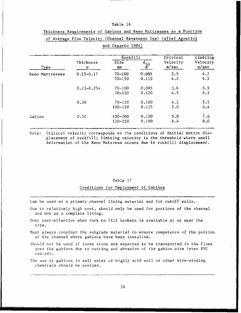
Table 16
Thickness Requirements of Gabions and Reno Mattresses as a Function
of Average Flow Velocity (Channel Revetment Use) (after Agostini
and Cesario 1984)
Rockfill Critical LimitingThickness Size d50 Velocity Velocity
Type m mm m m/sec m/sec
Reno Mattresses 0.15-0.17 70-100 0.085 3.5 4.270-150 0.110 4.2 4.5
0.23-0.254 70-100 0.085 3.6 5.570-150 0.120 4.5 6.1
0.30 70-120 0.100 4.2 5.5100-150 0.125 5.0 6.4
Gabion 0.50 100-200 0.150 5.8 7.6120-250 0.190 6.4 8.0
Note: Critical velocity corresponds to the conditions of initial motion dis-placement of rockfill; limiting velocity is the threshold where smalldeformation of the Reno Mattress occurs due to rockfill displacement.
Table 17
Conditions for Employment of Gabions
Can be used as a primary channel lining material and for cutoff walls.
Due to relatively high cost, should only be used for portions of the channeland not as a complete lining.
Host cost-effective when rock to fill baskets is available at or near thesite.
Must always consider the subgrade material to ensure competence of the portionof the channel where gabiorts have been installed.
Should not be used if loose stone are expected to be transported in the flows
over the gabions due to cutting and abrasion of the gabion wire (even PVCcoaed).
The use of gabions In salt water or highly acid soil or other wire-erodingchemicals should be avoided.
38
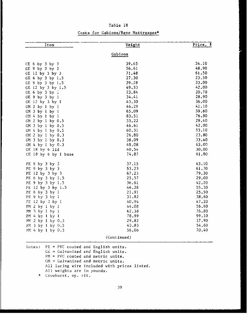
Table 18
Costs for Gabions/Reno Mattresses*
Item Weight Price, $
Gabions
CE 6 by 3 by 3 39.65 34.10GE 9 by 3 by 3 56.61 48.90GE 12 by 3 by 3 71.48 61.50GE 6 by 3 by 1.5 27.30 23.50GE 9 by 3 by 1.5 39.28 33.00GE 12 by 3 by 1.5 49.33 42.00GE 6 by 3 by 1 23.84 20.70GE 9 by 3 by 1 34.41 28.90GE 12 by 3 by 1 43.30 36.00GM 2 by I by 1 46.29 42.10GM 3 by I by 1 65.09 59.60GM 4 by I by 1 83.51 76.80CM 2 by 1 by 0.5 33.22 29.40GM 3 by 1 by 0.5 46.61 42.00GM 4 by I by 0.5 60.31 53.10GM 2 by I by 0.3 26.80 23.80GM 3 by I by 0.3 38.09 33.40GM 4 by 1 by 0.3 49.08 43.00GE 18 by 6 lid 40.54 30.00GE 18 by 6 by 1 base 74.87 61.80
PE 6 by 3 by 3 37.15 43.10PE 9 by 3 by 3 53.23 61.70PE 12 by 3 by 3 67.25 79.30PE 6 by 3 by 1.5 25.57 29.00PE 9 by 3 by 1,5 36.61 42.20PE 12 by 3 by 1.5 46.28 55.30PE 6 by 3 by 1 21.91 25.50PE 9 by 3 by 1 31.82 38.60PE 12 by 3 by 1 40.94 47.20I'M 2 by I by 1 44.08 56.60PM 3 by I by 1 62.38 76.80PM 4 by I by 1 78.99 99.10PM 2 by 1 by 0.5 29.82 37.90PM 3 by I by 0.5 43.83 54.60PM 4 by 1 by 0.5 56.06 70.40
(Continued)
Notes: PE = PVC coated and English units.GE = Galvanized and English units.PM = PVC coated and metric units.GM = Galvanized and metric units.All lacing wire Included with prices listed.All weights are in pounds.Crowhurst, op. cit.
39

Table 18 (Concluded)
Item Weight Price, $
Gabions (Continued)
PM 2 by 1 by 0.3 25.42 31.50PM 3 by I by 0.3 35.12 44.40PM 4 by 1 by 0.3 46.14 56.80PE 12 by 3 by I base 28.01 26.68
Reno Mattresses
GE 9 by 6 by 6 base 22.38 23.60GE 12 by 6 by 6 base 28.37 27.00GE 9 by 6 by 9 base 24.04 27.80PE 9 by 6 lid 14.26 13.10GE 12 by 6 by 9 base 30.98 35.50GE 12 by 6 lid 18.27 16.20PE 9 by 6 by 6 base 28.58 36.80PE 12 by 6 by 6 base 37.09 40.50PE 9 by 6 by 9 base 28.63 44.50PE 9 by 6 lid 17.51 21.70PE 12 by 6 by 9 base 37.45 57.50PE 12 by 6 lid 22.71 28.30PE 40 by 6 lid 71.30 100.00PE 40 by 6 by 9 base 120.15 185.60
40

installations is labor cost. Average man-hours for gabion/Reno Mattress
installation done by hand are:
a. 2-4 man-hours/cubic yard for gabions.
b. 0.5-1.25 man-hours/square yard for Reno Mattresses.
If portions of the gabion installation are mechanized, the final cost ends up
being about the same.* Presently, a good grade of short-haul (< 7 km)
Midwest aggregate, for example, runs about $15/ton (I cu yd = 1.5 tons). With
all costs taken into account, the average installed cost in Missouri is about
$80/cu yd.**
Cutoff wall
92. This technique places a vertical wall-barrier, installed to an
appropriate depth, at the top of the emergency spillway and/or at other loca-
tions along the channel.t Cutoff walls can be designed in a variety of types
and can be constructed of a number of materials. Such materials include con-
crete, sheet piles, logs, gabions, etc. (Table 19).
Table 19
Conditions for Employment of a Cutoff Wall
Situations where there is a high probability of headward cutting taking placeduring a flow event.
Effective when site conditions allow the wall to be keyed into a competentrock unit with minimal erosion potential.
Most effective when used as a series of walls,
Most suitable in weak rock with closely spaced discontinuities.
93. One example of a cutoff wall being considered is at the Sam Rayburn
Dam, east Texas, which embodies "the construction of a deep drilled pier
cutoff wall along the alignment of the existing spillway weir" supplemented by
a "series of three additional cascade walls across the spillway discharge
channel" (Cameron et al. 1986). The measure would be designed to "prevent
total failure of the spillway," but "extensive repairs would be required after
* Crowhurst, op. cit.
** Personal Communication, 1987, R. Russo, Maccaferi Gabions, Inc.,St. Louis, Missouri.
t Schaefer, op. cit.
41

the passage of any significant spillway discharge. This system has an esti-
mated cost of $50 million" (Cameron et al. 1986).
94. Costs related to employment of cutoff walls will vary depending on
the type of material and site depth conditions. The costs quoted here are
only for concrete walls (Table 20).
Table 20
Costs Related to Concrete Cutoff Wails
Technique Assumption Cost/unit
Excavated in the dry, Reinforced concrete, $20 to 40/ft2 of surfaceshored/formed less than 10 ft deep area (one side)
Excavated in the wet, Reinforced concrete, $25 to 50/ft 2
pumped, shored/formed less than 10 ft deep
Excavated in weak rock, Reinforced concrete, $30 to 70/ft 2
dry, unshored/unformed less than 10 ft deep
Removal of woody vegetation
95. Woody vegetation and fallen (or toppled) tre2s can cause turbulent
flow concentration, which, in turn, increases the erosive forces or can actu-
ally cause a logjam in the spillway channel. At the Grenada Dam in Missis-
sippi, one flow event caused channel widening which toppled a large number of
trees into the channel. A recommendation was made to remove these trees to
avoid the possibility of a logjam. Bodies of woody vegetation are also known
to increase the probability of damage through flow concentration, which
increases the velocity and flow rate in portions of the channel which are
adjacent to the vegetation. Vegetation removal was recommended at
Little Youghiogheny Dam No. 1, Maryland, during the National Dam Inspection
Program (Ackertheil and Associates 1979). Removal of woody vegetation would be
far less expensive than the possible damage that such vegetation could cause
during flooding (Table 21).
96. Costs related to vegetation removal will vary considerably. The
two end members of this cost range are the minimal outlay required for rough
mowing or herbicide treatment in an arid environment to the significant costs
related to grubbing-removal of small, rooted trees in a humid climate
(Table 22).
42

Table 21
Conditions Requiring Removal of Vegetation
When trees or shrubs of any kind are present on the floor of the emergencyspillway channel.
Most effectively employed as a preventive ý,easure; i.e., removing trees andshrubs as they begin to grow, either by hand or with an herbicide (in thiscase the use of an herbicide may be less expensive).
Table 22
Costs Related to Removal of Woody Vegetation
Technique Assumption Cost/unit
Rough mowing, Denial of substantial growth of woody vege- $125-175/hectaredry climate tation (per 12 months) $ 50- 70/acre
Rough mowing, Denial of substantial growth of woody vege- $500-650/hectacehumid climate tation (per 3 months) $200-265/acre
Herbicide, Initial kill of substantial growth $ 90-100/hectarehumid climate $ 35-110/acre
Spot cutting, Removal of substantial growth of woody $185-285/hectaredry climate vegetation, plus removal of cuttings $ 75-110/acre
(2-person crew)
Spot cutting, Removal of substantial growth of woody $370-560/hectarehumid climate vegetation, plus removal of cuttings $150-225/acre
(2-person crew)
Removal of erosional outliers
97. Erosional outliers are defined herein as any structure or natu-
rally occurring feature that has the tendency to concentrate flow and, there-
fore, increase the erosive force in a specific section of the emergency
spillway channel. Such features include access roads, fences, boulders, a
fault scarp or similar feature, or a stand of trees, etc. The presence of
these types of features can cause specific sections of an otherwise erosion-
resistant channel to be severely damaged. In the worst case such damage can
spread during the flow event and creatp a breach, through the spillway, or in
some very severe cases, through the main embankment, causing failure.
43

98. Removal of such features, in many cases will be relatively inex-
pensive. However, in situations where an access road crosses the spillway,
appropriate modifications may require large sums of money along with creative
engineering. Following the erosion assessment, a decision will need to be
made at each location as to the cost effectiveness of removing or modifying
all of the erosional outliers to address the problems of safety and financial
considerations that will be incurred in the event of flow. At many locations
it may be more effective to combine removal or modification with another mea-
sure to provide adequate channel protection (Table 23).
Table 23
Conditions for Removing Erosional Outliers
Any site condition that will interrupt flow should be considered for removal.
99. No costs are quoted herein for the removal of erosional outliers.
This is due to the fact that the types of outliers are quite variable, and the
cost of removal is totally dependent on the type. For example, the cost of
rerouting an access road will be quite different from the cost of grading or
removing a fault scarp.
Riprap
100. During one model study regarding the design of a rock-fill dam
(Shannon and Wilson 1961), it was found that the greatest protection against
erosion occurred if the rocks are placed in two layers with the rocks in the
bottom layer raked to grade, and the top layer placed with the thin dimension
vertical and the long dimension parallel to flow. Additionally, all of the
upper-layer stones were placed so that they were wedged against the downstream
rock. By placing rock in this manner, it was found that only the first row of
rock 4ould be disturbed during flow, and "when any one rock was displaced at
all, it was immediately swept downstream from the model" (Shannon and Wilson
1961) without disturbing any of the other rock. The conclusion of this study
is "that properly placed tabular rock with a long dimension noticeably greater
than its average minimum dimension is stable with the following slopes and
average riprap thickness dimensions":
44

1:6 slope - 0.5 m
1:5.5 slope - 0.66 m
1:5 slope - 0.77 m
101. When designing a riprapped emergency spillway surface, it is
important to determine the equivalent thickness of sufficiently large rock to
rasiSL the Lrdetive force of the design discharge. Depending on the gradient
and expected flow velocities, it may be necessary to use some type of filter
material to dissipate pore pressures and provide stability. Guidance for the
design of riprap protection is given in Shannon and Wilson (1960, 1961) and
HQUSACE (1970) (Table 24).
Table 24
Conditions for Employment of Riprap
Most cost-effective when rock cdn be obtained on or near the site.
Most appropriate where near-horizontal channel slopes exist.
When used over clays and/or silts and when high velocities are expected an
appropriate filter should be considered.
102. Lower Chapman Dam, Oregon, wh`ýh is owned and operated by the Star
Mountain Ranch (US Bureau of Land Management 1983), has a total capacity of
1,460 acre-ft, and is used for irrigation and flood control (US Soil Conserva-
tion Services 1982). The dam is 32 m (105 ft) high, and the emergency spill-
way was designed according to the "100 year exceedence interval to 1/2 PMF"
(US Soil Conservation Services 1982). The 100 year PMF at this dam was calcu-
lated to be 1,835 cfs. A large-flow event of February 1982 removed several
thousand cubic metres of material from the emergency spillway constructed in
an unconsolidated cobble, boulder, and sand alluvium (US Soil Conservation
Services 1982). Over this alluvium was placed 60-cm (2-ft) armour of angular
cobble and boulder-size basalt riprap (US Soil Conservation Services 1932).
All of the riprap was stripped by the 1982 flood event (US Bureau of Land Man-
agement 1983), and vertical erosion channels of 7 to 8 m (20 to 25 ft) were
created (US Soil Conservation Services 1982).
103. The prime remedial measure recommended was to compact onsite fill
to a 1:2 slope, overlaid with 2.6 m (5 ft) of riprap, held in place by a
welded mesh of No. 5 rebar, and secured by concrete cutoff trenches upstream
45

and downstream. The estimated cost of the treatment was $90,000 (US Soil Con-
servation Services 1982). Dimensions of the emergency spillway were not
included in the report; therefore, unit costs could not be determined
(Table 25).
Table 25
Costs Related to Riprap
Stone riprap; excavated from dedicatedquarry producing select rock $20-50/yd3
104. The recommended measures were not carried out by the owner, and a
flood the following March brought about a spillway failure which released
ahout 1,000 acre-ft of water from reservoir storage, following about 2 cm
(0.75 in.) of rain over the previous 24 hr (US Bureau of Land Management
1983).
Relief of uplift pressure
105. utherwise, intact rock masses bound by widely spaced discontinui-
ties (spaced at more than 1.0 m) are subject to hydrostatic uplift pressures
especially during flooding. Where these massive blocks are bound by a regular
network of open joints (such as at Black Butte Dam, California), uplift pres-
sures may be naturally relieved through the joint boundaries.
106. Measures to relieve uplift pressures should be considered at those
sites treated by closure of bounding joints, such as by grouting or a combina-
tion of grouting and rock bolting. A simplistic method of relieving uplift
pressure would be to place one or more centrally located, vertical boreholes
into each distinct joint block and terminate at some depth (say 30 to 60 cm)
below the most distinct lateral (horizontal) bounding discontinuity. Such
near-horizontal discontinuities can often be detected by manual probing with a
hooked stiff wire. Uplift pressure-relief boreholes should be relatively
small (70- to 100-mm diam) and backfilled with small-diameter granular
material, graded to act as a barrier to sedimentation plugging of the relief
hole yet porous enough to allow for pressure relief* (Tables 26 and 27).
Personal communication, 1986 (Oct), J. H. May, US Army Engineer WaterwaysExperiment Station, Vicksburg, Mississippi.
46

Table 26
Conditions for EmployinS Relief of Uplift Pressures
Any situation where large rock blocks are present, and the potential existsfor those blocks to be fragmented by uplift pressures during flow, thusbeing susceptible to plucking.
Rock blocks must be unweathered to a depth of less than 1 cm from surface.
Table 27
Costs Related to Relief of Uplift Pressures
Technique Requirements Costs
Pressure relief 70- to 100-mm diam, -5-ft-deep $900/day for drilling rig,boreholes (minimum) Trn-cone bit 25 holes/day, $8 to $11/ft
urabo lininc,
107. Ordinarily, there would be little need or applicability for the
use of vegetation in excavated spillways in hard indurated rocks, however,
vegetation may be helpful in spillways cut in softer rocks and in the outlet
channels. Selection of natural grasses for channel lining must be made on the
basis of climatic and soil characteristics. The grass must be chosen either
to provide stability as a function of projected flow velocity or on the basis
of discharge channel gradient. Bunch grasses, such as lespedeza, alfalfa, and
kudzu, can develop localized flow channels and are therefore unsatisfactory
for lining (Chow 1959). For gradients greater than 5 percent fine, uniformly
distributed sod-forming grasses (e.g., Kentucky bluegrass, Bermuda grass, and
smooth brome) are recommended. Fast establishing Bermuda grass, weeping love
grass, or annuals should be used for temporary protection until native or
other grassqF are established (Chow 1959). Chow also recommends that bunch
grasses be used to reduce silting. Grasses, in general, require semicohesive
soils as a rooting medium and 20-25 cm (8-10 in.) of precipitation per year
for sustenance.*
* Schaefer, op. cit.
47
108. Grass linings serve to "consolidate the soil mass of the channel
perimeter," and to retard bedload movement along the channel surface (French
1985). However, grass-lined channels cannot generally withstand prolonged
inundation and wetness, and they may lose vitality during seasonal dry periods
(French 1985). Maximum tolerable velocities for various grasses are given in
Table 26; conditions of employment are in Table 29; and costs are in Table 30.
109. Selection of grass species for channel lining should consider the
following factors:
a. Spare vegetal cover should be exposed to velocities less than3 ft/sec (0.91 m/sec).
b. Seeded vegetation can generally withstand velocities in therange of 3 to 4 ft/sec (0.91 to 1.2 m/sec).
c. Quickly developed dense sod is generally resistant tovelocities of 4 to 5 ft/sec (1.2 to 1.5 m/sec).
110. Additional flow resistance is gained by deep-rooted, long-stemmed
grass, such as fescues which lay over in flow. Such grasses can protect
slopes of 5 to 6 percent, with flow velocities as high as 8 to 9 ft/sec.*
111. When a grass lining is planned, consideration needs to be given to
the maintenance of the grass. The upkeep will not be as extensive as that of
maintaining a lawn. However, occasional repairs will be necessary to keep a
gnod continuous cover, and "volunteers" (trees and bushes) will require
removal vn an on-going basis.
112. It should be stressed that in case history after case history the
velocities experienced in spillway channels are much greater than those that
natural grasses can withstand, and, therefore, natural grasses should only be
considered in those special situations where the expected velocity is within
the range discussed above.
Geotechnical grass
113. The Construction Industry Research and Information Associa-
tion (CIRIA), of the United Kingdom, is in the process of performing tests on
grasses for spillway linings that are reinforced with geotextiles and concrete
lattices (Birchall and Pinyan 1986). Thus far, CIRIA has had great success
with both the concrete lattice and geotextile systems. The concrete lattice
systems perform the best when used in conjunction with a geotextile. This
combination proved to be very erosion resistant; however, it is somewhat
* Schaefer, op. cit.
48
S. . . . . . . . . . . ... . .. . . . . . .. .... . . . . . . . .... . . . ..~- - - - - - - . - - -

Table 28
Maximum Velocities for Grassed Channel Grade
(after French 1985)
Maximum Tolerable Velocity*
Gradient Range** Erosion-Resistant Easily ErodedCover percent Soils, ft/sec Soils, ft/sec
Fescue 5-6 8-9 5Bermuda grasst 0-5 8 6
5-10 7 510 6 4
BahiaBuffalo grassKentucky blue 0-5 7 5Smooth brome 5-10 6 4Blue grammat 10 5 3Tall fescue
Grass mixtures 0-5 5 4Reed canary 5-10 4 3
Lespedeza servicea ......Weeping love grass ......Yellow bluestem ......
Redtoptt 0-5 3.5 2.5Alfalfa ......Red fescue ......
Common lespedezat, ......
Sudan grasst 0-5 3.5 2.5
* Specify velocities exceeding 1 m/sec (5 ft/sec) only where good covers andproper maintenance can be obtained.
** Specify for slopes less than 10 percent except for vegetated side slopesin combination with a stone, concrete, or highly resistant vegetativecenter section.
t These annuals should be used on mild slopes (less than or equal to5 percent) or as temporary protection until permanent covers areestablished.
tt Specify for slopes less than 5 percent except for vegetated side slopes incombination with a stone, concrete, or highly resistant vegetative centersection.
tUse on slopes steeper than 5 percent is not recommended.
49

Table 29
Conditions for Employment of Grass Lining
Sufficient annual precipitation and appropriate temperatures.
Expected velocities are low enough to allow grass to provide desired level ofprotection.
Table 30
Costs Related to Grass Lining
Components Costs
Topsoil $ 20/yd 3
Seeding $ 940/acre
Sodding $ 5/yd2
Fertilizer (no insecticides) $ 710/acre
Maintenancemowing $ 100/acre/yrrefertilization $ 270/acre/yrweeding/pruning $2,000/acre/yr
Note: Costs taken from US Environmental Protection Agency (1985) and adjustedfor inflation.
Table 31
Conditions for Employment of Geotechnical Grass
Most appropriate in areas where climate is suitable for grass lining, butexpected velocities are greater than standard grass linings can withstand.
Appropriate for spillways in soil and soft rock.
Appropriate where aesthetics are important.
50

Table 32
Costs Related to Geotechnical Grass
Components Costs
Topsoil $ 20/yd 3
Seeding $ 940/acre
Sodding $ 5/yd2
Fertilizer (no insecticides) $ 716/acre
Maintenancemowing $ 100/acre/yrrefertilization $ 270/acre/yrweeding/pruning $2,000/acre/yr
Geotextile $ 0.70/ft2
Note: Costs taken from US Environmental Protection Agency (1985) andincreased by 5 percent per year for inflation.
i14. The most surprising portion of the CIRIA study was the performance
of grass J nin6 s that were only reinforced with a geotextile to strengthen the
root system. Geotextiles used in these tests were a three-dimensional nylon
mat and a tt.o-dimensional polyethylene mat. Bor gee 2xtiles performed in
such a way as to show that design velocities could be in the range of 14.8 to
18 ft/sec. Compared with the concrete mesh, the geote•ctjles are approximately
$0.70/sq ft. By comparing the CIRIA velocities with those in the previous
part, it can be seen that the geotextile actually doubles erosion resistance
of the grass with respect to velocity.
Flow rerouting
115. Flow rerouting can be achieved by a number of devices. At Sam
Rayburn Dam In east Texas, a new ogee weir, which would raise the level of the
emergency spillway crest, was considered as a preventive measure by the
11S Army Engineer District, Fort Wcrth. Also, eight 40- by 33-ft tainter
gates, located in the mair 'am, would divert the flood discharge from the
emergency spillway and route it to the main channel of the Angelina River.
This ine•sure would cost approximately $58 million (Cameron et al. 1986).
1 11. In situatioiis where the emergency spillway is quite large, located
ij t1ighiy erodibhe a] luvial or residual deposi ts, and no type of lining is
feasible, consideration can be given to rerouting the flow. One possible
51

condition that might call for such a measure is when the emergency spillway is
actually being used as farmland (not a recommended practice) and, therefore,
is very erosive and not feasible for lining.
117. It should be remembered that this option only reduces the possi-
bility of flow going over the emergency spillway and does not improve the
emergency spillway channel in any way. In most situations, this option will
also be very expensive and, therefore, should only be considered as a last
resort, after all other options have been considered. When considering this
option, it would be important to evaluate the entire reservoir area for
another possible location of the emergency spillway. There may be situations
where relocation of the emergency spillway would be less expensive than adding
a new service spillway (Table 33).
Table 33
Conditions for Employment of Flow Rerouting
Considered only as a last resort when there are no other options forremediation.
118. Costs related to flow rerouting will be greatly variable depending
on what is to be done. Such costs will be related to the materials and con-
structions costs incurred during the raising of an emergency spillway weir,
and/or the construction of additional service spillways, and/or the construc-
tion (relocation) of a new (or additional) emergency spillway.
Compaction
119. Emergency spillway channels excavated into unconsolidated alluvial
or residual deposits are especially susceptible to erosion, especially when
the fine-grained materials are low in cohesion. Compaction may be very help-
ful in reducing erodibility. Creating a more cohesive mass will in turn
reduce the erodibility. Compaction densification of the uppermost 6-12 in. of
the flow surface will reduce the erodibility. Compaction relative densities
of less than 90 percent are generally sufficient for this purpose. The ero-
sion resistance of some spillway channels can often be increased to an appro-
priate degree by compaction only. Compaction is especially effective when the
combined silt and clay fraction is greater than about 25 percent. Among
poorly consolidated soils, loess deposits are generally too silt-rich to yield
52

an increase in their erosion resistance. Recompaction may be required after
significant flood events and after freeze-thaw cycles.
120. Compaction is particularly effective when used in conjunction with
other measures. For example, subgrade compaction below a topsoil grass-lining
layer will provide enhanced protection against erosion in the event that a
section of the grass fails. Concrete or gabion-type linings often require
compaction of unconsolidated subgrade to protect against settlement (Tables 34
and 35).
121. Compaction can be carried out with a standard roller. A southern
California (Gutschick 1985) canal, constructed in montmorillonitic clay soil,
has exhibited considerable erosion resistance after being mixed with quicklime
and being compacted with a sheeps-foot roller. Mixing with quicklime tended
to have a pozzolanic effect on the clay soil. Other than being mixed with
Table 34
Conditions for Employment of Compaction
When the spillway is bedded in sufficient thickness (Z 1 it) of unconsolidatedmaterial.
Especially when this material has cohesion; e.g., is of silt or clay particlesize.
In climates in which grass linings are not possible because of other factors.
Table 35
Costs Related to Compaction
Conditions Cost
Tilled, meisture-controlled, two 6-in. lifts,onsite material $1-2/yd2
Onsite, hauled, mixed, moisture-controlled, 2two 6 -in. lifts $1.50-3/yd
onsite, moisture-controlled, mixed in place,additive soil or mineral, two 6-in. lifts $2-4/yd2
Onsite, hauled, moisture-controlled, mixedadjacent to spillway, addItive soil or 2mineral, two 8-in. lifts $2.50-5/yd
53
lime and being compacted, the canal is unprotected. Very little erosion has
occurred after 12 years of service, including service under one peak flow of
5,300 cfs (Gutschick 1985). This is evidenced by the fact that 12-year old
canal grader marks were still visible on the surface.
Multiple use options
122. There are certain conditions in which the location of the spillway
makes it possible to use the spillway for more L .n one purpose. In these
situations the uses will compliment each other. One example of such a use is
constructing a parking lot in the emergency spillway channel. There may also
be other possibilities.
123. At some locations, dams have been constructed in urban areas or
recreational park areas. In these situations, if the spillway is conveniently
located and it is presently unlined, one possible option would be to construct
a parking lot in the channel. To be effective in creating an erosion-
resistant channel, the parking lot in such cases would have to be concrete or
asphalt paved instead of gravel and oil. This option has been used in a
number of emergency spillways located in the US Army Engineer Division, Ohio
River* (Table 36).
Table 36
Conditions for Employing Multiple Use Options
Appropriate when spillway is located near populated areas or located in parkareas.
Any situation where a second use will reduce the erodibility of the spillwayand continue to address safety and proper reservoir use.
Costs Related to Multiple Use Options
Gravel (compacted, 12 in.) $9/yd2 (US EnvironmentalProtection Agency 1985)
Asphaltic concrete, 6 in. Variable
Asphaltic concrete, 6 in., with 8-in.pressure relief gravel base course Variable
* Personal Communication, 1987, C. P. Cameron, University of SouthernMississippi, Hattiesburg, Mississippi.
54

Modified ogee weir (ski-jump structure)
124. In situations where the outlet slope on the emergency spillway
channel is steep (approaching a small cliff), a ski-jump structure can be
installed at the top of this knickpoint. Hydraulic structures of this type
will cause the water to shoot out away from the base of the cliff and reduce
the possibility of undercutting. Such structures are n-.: only less expensive
than a complete channel lining but in some situations are more effective in
that they substantially arrest the process of headcutting.
125. Structures of this type can be used in situations where the chan-
nel is lined with a competent, relatively erosion-resistant geologic unit that
extends to the point of the cliff-like outlet slope. This would be particu-
larly important if the competent unit is not as thick as the height of the
cliff (see Figure 4) (Tables 37 and 38).
126. Concrete baffles were used to repair the spillway at the Kerri-
ville State Hospital Dam, Texas. At this location, three reinforced concrete
baffles were placed across the spillway to retard the movement of riprap that
had been used to bring the spillway to hydraulic grade. The baffles used were
9 in. by 5 ft by 100 ft, with 4-in.-diam drains placed 1.5 ft below the top of
the baffle placed at 10-ft centers. During 1978, a flow of 3,200 cfs
(90.6 cm/sec) was accommodated by the baffles with only a minor amount of
acceptable riprap displacement (Tables 39 and 40).
55

FLOW
0
3 W-2
10
a. Spillway channel before remediation
F LOWo mom
* ~ ~ ~ M DFE OGE WEIR***. ~ . *.*~.
b plwycanl fe eeito
Figure ~ ~ ~ ~ IP P D.UeoEamdfedoe e RasaRemeC aor prevntiv mesReFRE
56 CEEEEG

Table 37
Conditions for Employing Modified Ogee Weir
Any situation where the potential for undercutting is high, i.e., a very steepoutlet slope.
Especially appropriate at steep discharge slopes with very erodible underly-ing geologic material.
Table 38
Costs Related to Modified Ogee Weir
Components Cost
Scaling of loose, jointed, and/or 0.3 cycles/yd2 $ 8-12/yd2
bedded rock at vertical inter- of exposed face (one face)face with ogee; by manual means
Dental removal of loose, 0.3 cycles/yd 2 of $15-30/yd 2
weathered, jointed, and/or exposed surface (base sur-bedded rock at base of ogee; face area)by hydraulic means
Table 39
Conditions for Employing Baffles
Any situation where cut walls would be appropriate but where drainage throughthe walls is needed.
Table 40
Costs Related to Baffles
Components Costs
Excavation into cohesionless, Formwork required $25-50/yd2 face area,unconsolidated spillway one sidesubstratum; 5-fL depth
Placement of drain septum and Formwork required $55-70/yd2 face area,reinforced-concrete wall one side
57

PART IV: CONCLUSIONS AND RECOMMENDATIONS
127. REMR research at WES has established that remediation of emergency
spillway erosion damage is a relatively new, but major concern to CE Districts
and to other dam owners and operators. The REMR work unit conducting the cur-
rent investigation has identified numerous CE and other Federal, institu-
tional, and private-sector dams that have experienced erosion damage in their
unlined spillway channels (Cameron et al. 1986). However, only a few projects
have implemented or planned remedial and/or preventive measures.
128. Potentially useful remedial engineering techniques include cement-
based methods such as grouting, shotcrete, soil cement/rollcrete, and high-
strength unreinforced and reinforced concrete as well as rock bolts, wire
mesh, gabions, and riprap. Potentially useful erosion preventive measures
include construction of energy dissipators, cutoff walls, and the removal of
vegetation and other obstacles to flow. Flow rernuting, the relief of uplift
pressures, and the placement of geotechnical and natural grasses (especially
in poorly lithified rocks and soils) may also offer useful alternatives. The
majority of these remedial techniques have been utiliz. d p• 'iously in various
erosion protection scheres (e.g., streambanks, canals, evees, etc.); however,
their use in unlined emergency spillway channels has rlt been extensive and
there is little document.,ion available. The selectio c. a particular
remedial technique will depend upon site conditions and co.ts which are highly
variable for a giver metho(.
129. The present study established a need fr more aublished documenta-
tion of performance and effectiveness of remedia: -•ee a- w-o1 as efforts
to predict rock erosion in emergency spillway channel, by t~e use of erosional
indices. It is believed that case histories, enlL-ti-s ad fr--- rankings
based on erosional indices have been written on the sucýe-; tl anc uinsuccess-
ful application of a variety of remedial technologies. Hl)we er, manr ')f these
reports are unpublished and, therefore, not readily availablc.
Cooiclusions
130. Remediation design is highly site-speclfic, must be ci'-t-
effective, address p-iblic safety, and provide continued reservoir operatirs
for its intended use.
58
131. Selection of appropriate remedial measures is complicated by
hydraulic design variables, geotechnical conditions, public safety, downstream
impacts, and Congress-mandated purposes of the reservoir.
132. There is a need to produce documentation relating to the perfor-
mance of remedial techniques alre-ady chosen and implemented in emergency
spillways and channels which have experienced erosion damage or where such
damage is anticipated.
133. An important option in emergency spillway and channel remediation,
not always available in most other engineering projects, is that the remedial
measure or structure need not be permanent, especially in those spillway chan-
nels which only rarely experience flow events. Thus, the "impermanent struc-
ture" is a viable remedial option in some cases.
134. Physical and numeric model studies are useful when remediation
design involves high-cost measures. These studies have an advantage in that
many combinations of parameters can be tried tor a relatively small expense,
especially if numerical models are being used. However, the effectiveness of
model studies is a function of thorough hydrologic, hydraulic, and geotechni-
cal characterization of the site under consideration. Models should not be
considered if input parameters are poorly known or if time and money con-
straints do not allow for proper mo'hi design and use.
135. Selection of remedial technique(s) must be established by site-
specific characterization of the rocks forming an unlined spillway channel in
terms of rock composition(s), hardness, structure and stratigraphic disconti-
nuities, and precursor erosion elements--all of which determine rock erodibil-
ity and its rate.
136. Erosion probability indices based on methods which combine rock-
mass parameters (composition, hardness, structural discontinuity, etc.) which
determine "rippability," with lithostratigraphic continuity, may allow for
site pr~oritization in terms of the need for remedial and preventive
techniques.
137. Suitable remedial engineering can be designed for virtually every
spillway but in most cases will retain an element of uncertainty as relates to
the factor of safety in achieving remediation goals. This uncertainty relates
t- tie characterization of site geotechnical factors and the selection of
ih i --related variables. These factors, strength, abrasive resistance, and
59

chemical stability of remediated earth materials must be determined in terms
of the hydraulic stresses generated by spillway overflows.
138. Natural grasses combined with geotextiles may provide cost-
effective erosion prevention in emergency spillway channels excavated in soft,
poorly indurated, rock strata and soils.
Recommendations
139. Compile a list of varied remediated unlined spillway channels on a
nationwide (or even worldwide) basis. Document the erosion damage caused or
anticipated. These spillway channels should then be monitored for performance
of remediation during future flow events. It is suggested that preflood and
postflood photographs and videos be used to provide visual documentation of
the performance of remediation employed.
140. Review, periodically by WES, research currently being conducted by
CIRIA in the United Kingdom on the performance of natural and geotextile
grasses in providing cost-effective erosion prevention in some unlined spill-
way channels.
1'1. Conduct detailed site-specific studies in selected Districts to
test the validity of EPI (both geoterhnical and hydraulic) derived from com-
bining "rippability" with lithostratigraphic continuity factors as well as
hydraulic factors. If valid, this approach should then be employed by Dis-
tricts to prioritize unlined channels in terms of remedial or preventive engi-
neering works. These site-specific studies should also be directed toward
developing methods for calculating factors of safety.
60

REFERENCES
Ackenheil and Associates. 1979 (Jul). "Little Youghiogheny River Site Num-ber I., Ohio River Basin, Cherry Glade Run, Garrett County, Maryland,"National Dam Inspection Program, Phase I Inspection Report, DTIC No. 802962AD-A088 788/5, Baltimore, MD.
Agostini, R., and Cesario, L. 1984. "Sand Asphalt Mastic Grouted Reno Mat-tresses for Impermeable Rivetments," unpublished paper, presented at Proceed-ings, Materials for Dams, December 12-14, (available Maccaferi Gabions, Inc.),Monte Carlo.
Albritton, J., Jackson, L., and Bangert, R. 1984 (Oct). "Foundation GroutingPractices at Corps of Engineers Dams," Technical Report GL-84-13, US ArmyEngineer Waterways Experiment Station, Vicksburg, MS.
American Geological Institute. 1987. Glossary of Geology, Washington, DC.
Bennett, R. D., Hignett, H. J., Johansson, S., Patrick, D. M., Taylor, P. A.,Smith, H. J., and McAneny, C. C. 1.985. "State-of-the-Art Technology for DeepTunnels and Shafts in Rock," Technical Report GL-85-1, US Army Engineer Water-ways Experiment Station, Vicksburg, MS.
Birchall, J., and Pinyan, C. 1986 (Aug). "Grass Roots Approach to Spill-ways," Engineering News Records, Vol 217, No. 9, pp 40-41.
California Department of Natural Resources. 1974. "Spillways," InformalReport, Field Engineering Branch, Department of Water Resources, Sacramento,
Cameron, C. P., Cato, K. D., McAneny, C. C., and May, J. H. 1986 (Aug)."Geotechnical Aspects of Rock Erosion in Emergency Spillway Channels," Techni-cal. Report REMR-GT-3, US Army Engineer Waterways Experiment Station,Vicksburg, MS.
Cameron, C. P., Patrick, D. M., Cato, K. D., and May, J. H. 1988. "Geotech-nical Aspects of Rock Erosion in Emergency Spillway Channels, Report 2,Analysi3 of Field and Laboratory Data" (in preparation) TechnicalReport REMR-GT-3, US Army Engineer Waterways Experiment Station, Vicksburg,MS.
Chuw, V. T. 1959. Open-Chainiel Hydraulics, McGraw-Hill, New York.
Copeland, R. R. 1980 (Oct). "Old River Overbank Structure Outlet Modifica-tions," Miscellaneous Paper HL-80-5, US Army Engineer Waterways ExperimentStation, Vicksburg, MS.
Farrow, E. S. 1895. Farrows Military Encyclopedia, a Dictionaru ,i MilitaryKnowledge, Military-Naval Publishing Company, Vol 1, New York.
French, H1. F. 1985. Open-Channel Hydraulics, McGraw-Hill, New York.
(;ordon, F. R. 1965. "Frosion of the Bywash Spillway at Serpentine Dam:Western Australia," Geological Survey Annual Report, Perth, Australia,pp 28-30.
Gutschick, K. A. 1985 (May). "Canal Lining Stabilization Proves Successful."lir and Quarry, pp 58-60.
61

Headquarters, Department of the Army. 1944 (Jan). "Dictionary of UnitedStates Army Terms," TM 20-205, Washington, DC.
Headquarters, US Army Corps of Engineers. 1965 (Mar). "Hydraulic Design ofSpillways," Engineer Manual EM 1110-2-1603, Washington, DC.
. 1970. "Hydraulic Design of Flood Control Channels," EngineerManual EM-I10-2-1601, Washington, DC.
. 1978 (Sep). "Tunnels and Shafts in Rock," EngineerManual EM 1110-2-2901, Washington, DC.
_ 1983 (Jun). "Rock Mass Classification Data Requirements for Rip-pability," Engineering Technical Letter ETL 1110-2-282, Washington, DC.
Holland, T. C. 1983 (Sep). "Abrasion-Erosion Evaluation of Concrete Mixturesfor Stilling Basin Repairs, Kinzua Dam, Pennsylvania," MiscellaneousPaper SL-83-16, US Army Engineer Waterways Experiment Station, Vicksburg, MS.
Holland, T. C., Krysa, A., Luther, M. D., and Lui, T. C. 1986. "Use ofSilica-Flume Concrete to Repair Abrasion-Erosion in the Kinzua Dam StillingBasin," Journal of the American Concrete Institute, Vol 83, No. 2, p 335.
Merritt, F. S., ed. 1968. Standard Handbook for Civil Engineers, McGraw-Hill, New York.
Murphy, T. E., and Cummins, R. S., Jr. 1965 (Jan). "Spillway Modifications,Mirafloraes Dam, Panama Canal Zone; Hydraulic Model Investigation," US ArmyEngineer Waterways Experiment Station, Vicksburg, MS.
Murphy, W. L. 1985. "Geotechnical Description of Rock and Rock Masses,"Technical Report GL--85-3, US Army Engineer Waterways Experiment Station,Vicksburg, MS.
Redlinger, J. F., Chairman, Copen, M. D., Judd, W. R., Matthews, J. S.,Perdue, J. M., Jr., Sherlock, P., Vithalani, J., Wahler, W. A., andWilson, G. R. 1975. "Lessons From Dam Incidents USA:, The Committee onFailures and Accidents to Large Darns of the United States Committee on LargeDams," Proceedings, American Society of Civil Engineers, NY.
Sage, R. 1977 (Apr). "Mechanical Support; CANMET" (Canada Centre for Mineraland Energy Technology, formerly Mines Branch, Energy, Mines and ResourcesCanada), Pit Slope Manual, Chapter 6, CANMET Report 77-3, p 111.
Shannon and Wilson, Inc. 1.960 (Aug). Consulting Geotechnical Engineers andGeologists. "Valsetz Dam Investigation," Seattle, WA.
. 1961 (Mar). Consulting Geotechnical Engineers and Geologists."A Report on Soma Factors Regarding the Design of a Rock Dam at Valsetz,Oregon," Seattle, WA.
Simons, D. B., Chen, Y. H., and Swenson, L. J. 1984 (Mar). "Hydraulic Testto Develop Design Criteria for the Use of Reno Mattresses," Civil EngineeringDepartment, Colorado State University, Fort Collins, CO, and Simons, Li, andAssociates, Inc., Fort Collins, CO.
Smith, G. 1779. Universal Military Dictionary, printed f-r J. Millan,Whitehall, London.
Thomas, B., Brookes, W., Runge, B., and Andrews, J. 1983 (May). US Bureau ofLand Management, "Report on Lower Chapman Dam," Vale Oregon District.
62

US Environmental Protection Agency. 1985 (Oct). 1985 Handbook; RemedialAction at Waste Sites, Report No. EPA/625/6-85/006, Hazardous Waste Engineer-ing Research Laboratory, Office of Research and Development, Cincinnati, OH.
US Soil Conservation Services. 1982 (Sep). "Summary Engineering Report,Design and Construction and Spillway Erosion, Lower Chapman Reservoir, StarMountain Ranch, Riverside, Oregon," Century West Engineering Corporation,Bend, OR.
Weaver, J. M. 1975 (Dec). "Geological Factors Significant in the Assessmentof Rippability," Die Sievele Ingenieur in Suid Afrika, pp 313-316.
63
- - - -- - -


![Technical Report REMR-CS-45 September 1994 of Engineers AD … · 2011-05-13 · Technical Report REMR-CS-45 September 1994 of US Engineers Army Corps AD-A285 l111t1l ]t11111[ I I](https://img.pdfslide.us/doc/110x75/5f47d13a9383701a85554b97/technical-report-remr-cs-45-september-1994-of-engineers-ad-2011-05-13-technical.jpg)