Embed Size (px)
Citation preview
+
Straight-Through Cable Construction
Lab 4
+Data Transmission
In data transmission system, the transmission medium is the physical path between transmitter and receiver.
The transmission medium that are used to convey information can be classified as :
Guided
Unguided
+Guided Vs. Unguided medium
Guided media (Wired) provide a physical path along which the signals are propagated; these include twisted pair, coaxial cable, and optical fiber.
Unguided media (Unwired) employ an antenna for transmitting through air, vacuum or water.
Unguided transmission techniques commonly used for information communications include broadcast radio, microwave, and satellite.
+Guided Transmission media
For guided transmission media, the transmission capacity, in terms of either data rate or bandwidth, depends critically on the distance and on whether the medium is point to point or multi point
The three guided media commonly used for data transmission are twisted pair, coaxial cable, and optical fiber.
+Twisted Pair
The least expensive and most widely used guided transmission medium is twisted pair.
Physical Description : A twisted pair consists of two insulated cooper wires arranged in a regular spiral pattern. A wire pair acts as a single communication link.
+Shielded and unshielded Twisted Pair
Twisted Pair comes in tow varieties:
1. unshielded Twisted Pair (UTP) :
Is ordinary telephone wire, office buildings, this is least expensive of all the transmission media commonly used for LAN and is easy to use to work with and easy to install.
unshielded Twisted Pair is subject to external electromagnetic interference, including interference from nearby Twisted Pair and from noise generated in the environment. A way to improve the characteristics of this medium is to shield the twisted pair with a metallic braid sheathing that reduces interference.
+Shielded and unshielded Twisted Pair
2. Shielded Twisted Pair (STP):
This Shielded Twisted Pair provides better performance at higher data rats. However, it is more expensive and more difficult to work with than unshielded Twisted Pair
+Category 5
Category 5:
UTP cables and associated connecting hardware whose transmission characteristics are specified up to 100 MHz
Category 5 has been superseded by the Category 5e (enhanced) specification
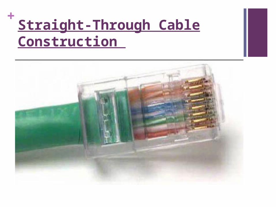
+Straight-Through Cable Construction
+Objective
Build a Category 5 or Category 5e Unshielded Twisted Pair (UTP) Ethernet network patch cable or patch cord.
Test the cable for continuity and correct pinouts, the correct color of wire on the right pin.
+Background
The cable constructed will be a four-pair, eight-wire, straight-through cable, which means that the
color of wire on Pin 1 on one end of the cable will be the same as that of Pin 1 on the other end. Pin 2 will be the same as Pin 2, and so on. The cable will be wired to either TIA/EIA T568B or T568A standards for 10BASE-T Ethernet, which determines what color wire is on each pin. T568B, also called AT&T specification, is more common in the U.S., but many installations are also wired to T568A, also called ISDN.
+Background
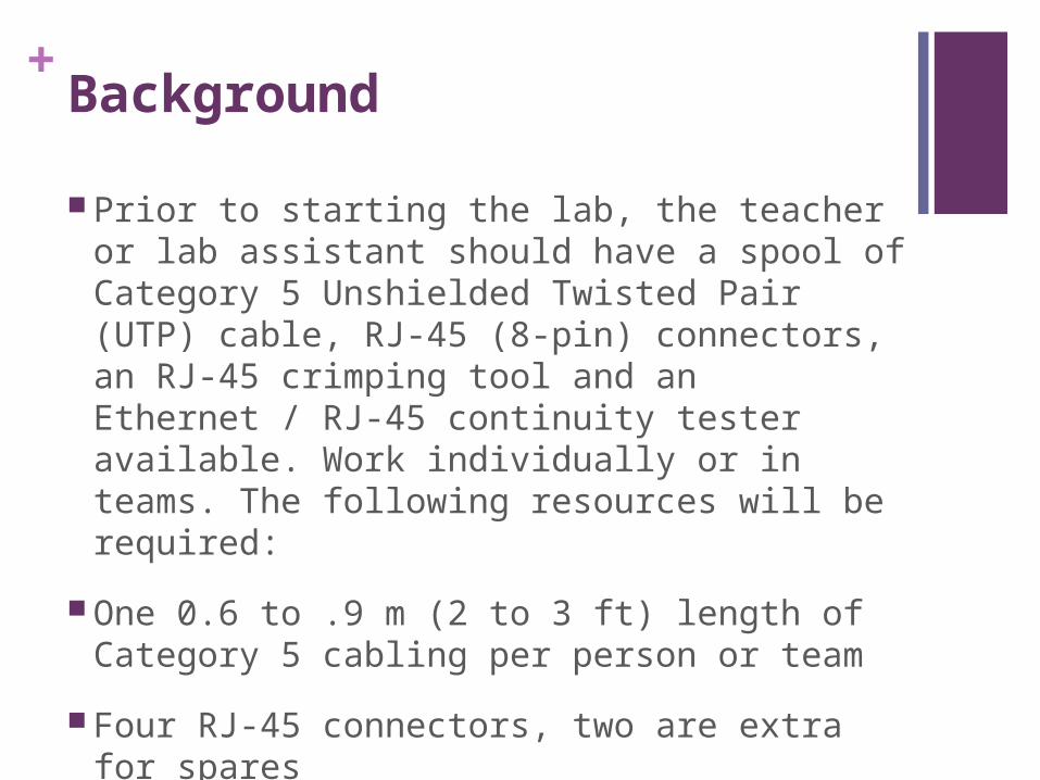
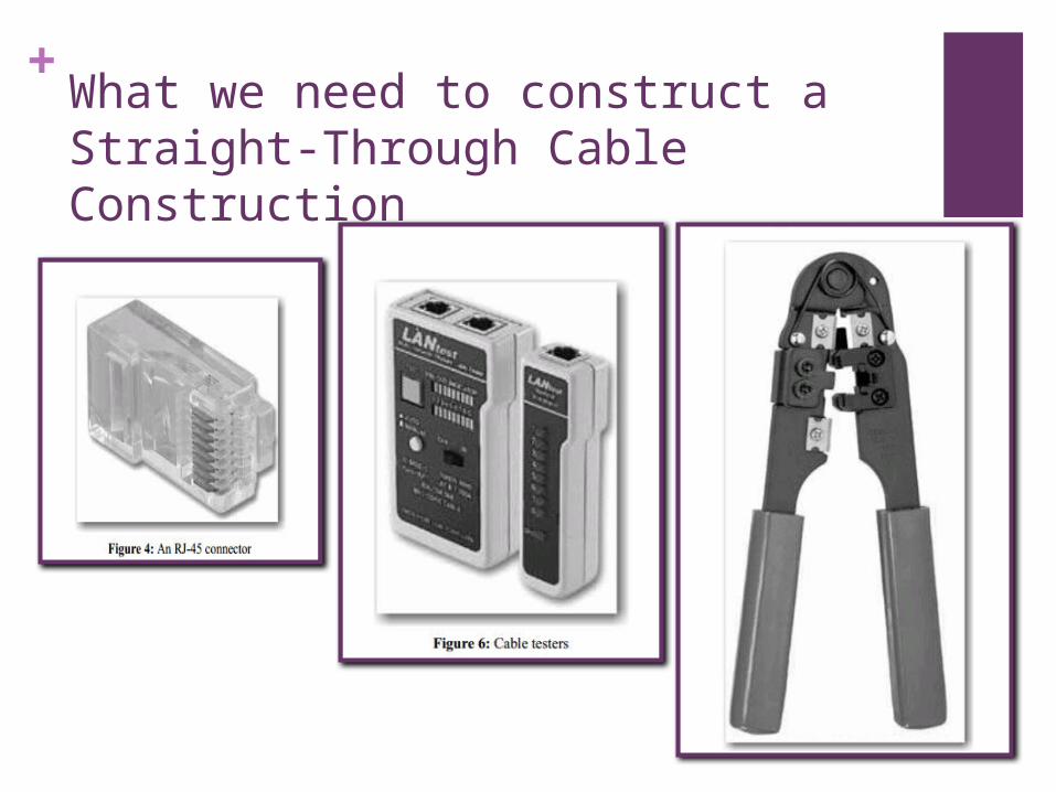
Prior to starting the lab, the teacher or lab assistant should have a spool of Category 5 Unshielded Twisted Pair (UTP) cable, RJ-45 (8-pin) connectors, an RJ-45 crimping tool and an Ethernet / RJ-45 continuity tester available. Work individually or in teams. The following resources will be required:
One 0.6 to .9 m (2 to 3 ft) length of Category 5 cabling per person or team
Four RJ-45 connectors, two are extra for spares
?RJ-45 crimping tools to attach the RJ-45 connectors to the cable ends
+Background
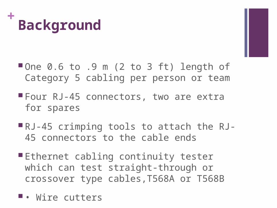
One 0.6 to .9 m (2 to 3 ft) length of Category 5 cabling per person or team
Four RJ-45 connectors, two are extra for spares
RJ-45 crimping tools to attach the RJ-45 connectors to the cable ends
Ethernet cabling continuity tester which can test straight-through or crossover type cables,T568A or T568B
• Wire cutters
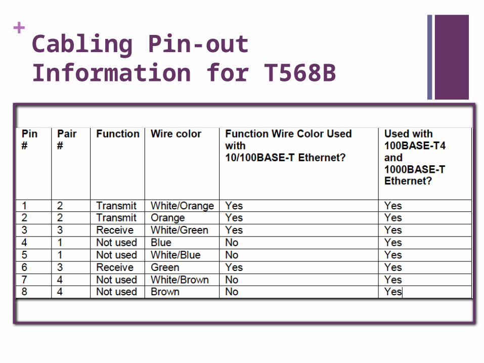
+Cabling Pin-out Information for T568B
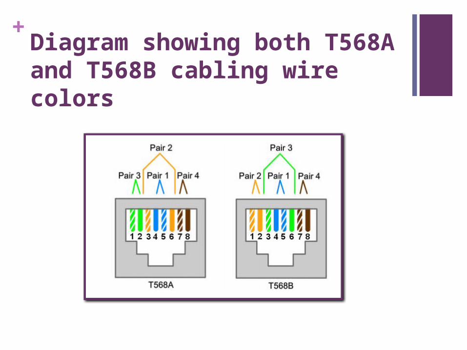
+Diagram showing both T568A and T568B cabling wire colors
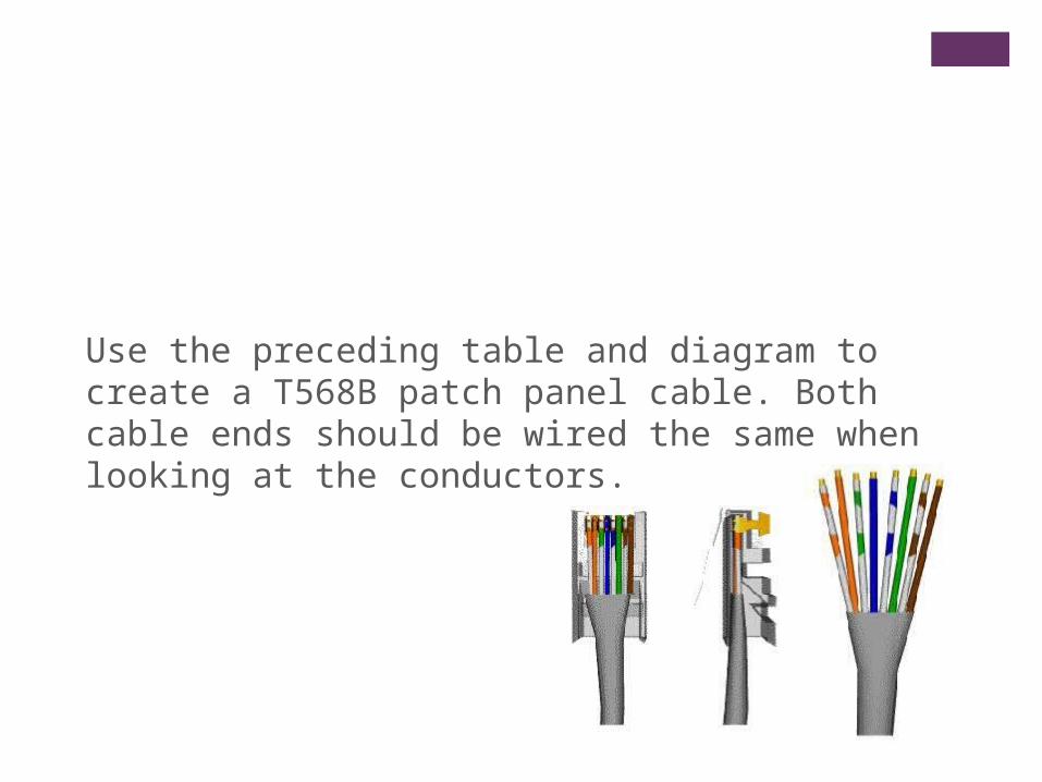
Use the preceding table and diagram to create a T568B patch panel cable. Both cable ends should be wired the same when looking at the conductors.
+What we need to construct a Straight-Through Cable Construction
+Step 1
Determine the distance between devices or device and plug. Add at least 30.48 cm (12 in.) to the
distance. The maximum length for this cable, according to TIA/EIA structured wiring standards is 3 m (9.84 ft), although this can vary. Standard lengths are 1.83 m (6ft) and 3.05 m (10 ft).
+Step 2
Cut a piece of stranded Category UTP cable to the desired length. Use stranded cable for patch
cables because it is more durable when bent repeatedly. Solid wire is used for cable runs that are
punched down into jacks.
+Step 3
Strip 5.08 cm (2 in.) of jacket off of one end of the cable.
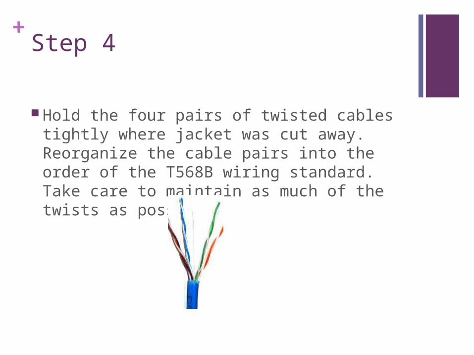
+Step 4
Hold the four pairs of twisted cables tightly where jacket was cut away. Reorganize the cable pairs into the order of the T568B wiring standard. Take care to maintain as much of the twists as possible
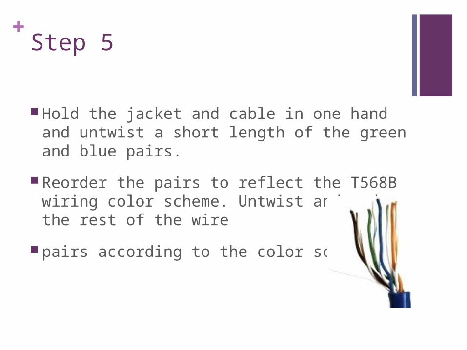
+Step 5
Hold the jacket and cable in one hand and untwist a short length of the green and blue pairs.
Reorder the pairs to reflect the T568B wiring color scheme. Untwist and order the rest of the wire
pairs according to the color scheme.
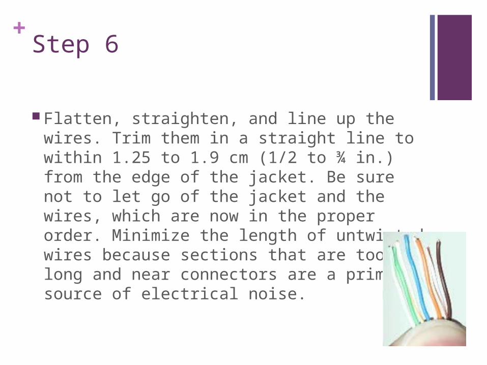
+Step 6
Flatten, straighten, and line up the wires. Trim them in a straight line to within 1.25 to 1.9 cm (1/2 to ¾ in.) from the edge of the jacket. Be sure not to let go of the jacket and the wires, which are now in the proper order. Minimize the length of untwisted wires because sections that are too long and near connectors are a primary source of electrical noise.
+Step 7
Place an RJ-45 plug on the end of the cable, with the prong on the underside and the orange pair to the left side of the connector.
+Step 8
Gently push the plug onto wires until the copper ends of the wires can be seen through the end of
the plug. Make sure the end of the jacket is inside the plug. This provides for stress relief and to
ensure that all wires are in the correct order. If the jacket is not inside the plug, the plug will not be
properly gripped and will eventually cause problems. If everything is correct, crimp the plug hard
enough to force the contacts through the insulation on the wires, completing the conducting path.

+Step 9
Repeat Steps 3 through 8 to terminate the other end of the cable. Use the same scheme to finish the straight through cable.
+Step 10
Test the finished cable. Have the instructor check the finished cable. How is it possible to tell if the cable is functioning properly?
Check the following:
1. Are the correct wires in the correct position on pins 1 thru 8?
2. Is the sheathing inside the connector and untwisting within the specifications?
3. Does the cable test correctly, with all pins crossed, with cable tester?