Embed Size (px)
Citation preview

Table of Contents
Hatz Diesel of America, Inc. W229 N1645 Westwood Drive P.O. Box 258 Waukesha, WI 53187-0258
Fax: 2621 544-6120 E-Mail: sales@.?hatzusa.com Web site: www.hatzusa.com
Ph: 2621 544-0254
SERIAL NO. NFOFWATION/HOW TO USE YOUR PARTS MANUALR.R.0.
KITS CATALOG
BASIC ELECTFUCALL & M ELECTRICAL SYSTEM AND
TESTINGBLECTRTCAL PRINTS
TROUBLESHOOTING GUIDE
WARRANTY
READY INDEX- INDEXING SYSTEM

information SALES Bulletin No. SE02C 0
0 ENGINEERING Date OW0 1/99 m SERVICE 0 PARTS
Subject= SERIAL NUMBER DATA PLATE - LOCATION AND INFORMATION (Information Bulletin SE02B should be discarded and replaced with SE02C)
TYP = Engine Type and Model
,.@ MOTORENFABRIK NO. = Serial Number* P KENNZ. = Customer-Specification Number
(on some engines) Output in kW.
ABWAUSF. = Execution Code (not used in USA)
CM3 = Engine Displacement
8 PV = Special Factory Adjustment Lb 7 NH = Fuel Rack Setting in Millimeters
MIN-l= Maximum Engine Speed (R.P.M.)
Sample Serial Number 024 10 78 123456 Type Series Y W Consecutive Model of Numbering (E79) Manufacture
*Beginning in 1994 the 12-digit serial number was increased to 13 digits. The TypeModel designation is now preceded with a zero because of the 3-digit model numbers.
I
David Carlson, Service Manager
c:\sEO3C.~am (dls) 8/01/99
lB20 lB30
On center of air ducting on PTO side.
Later models, also on crankcase by oil fill plug.
1B20V 1B30V
On center of air ducting between muffler and air cleaner on back side (can’t see it in this view) and on crankcase by side oil fill plug.
E671 E672 E673
On crankcase housing surrounding flywheel (injection pump side),
E71 E75 E79 E780 E785 E786
On air ducting below air cleaner near dipstick.

E80 ES5 E88 ES9
Early: On air ducting near exhaust poa (early),
Late: Near throttle lever (late).
S d l block - 1D30/3 1 1D4014 Large block - ID60 lD80/81
Early: On air filter housing.
9 \ Late: Onflywheelhousing (iijktion pump side).
EAKLY
1/50
1D30/3 1C 1D40/41C 1D60C lD80/81C
On sheetmetal panel on oil dipstick side.
Same location on the engine as above.
1D90V lD9OW
On flywheel housing, injection pump side.

E 950
.
Early: On air ducting behind air filter (early),
Late: Near oil filter (late),
2G30 2G40
On air ducting above flywheel.
2782 2788 2789 2790
Near breather tube on flywheel side,
El08 2108 D108 V108
On air ducting behind fan

2L30 3L30 4L30 2L31 3L31 4L31 2L40 3L40 4L40 2M31 3M31 4M31 2M40 3M40 4M40 2M41 3M41 4M41
Below exhaust manifold behind timiig gear cover,
Silent Packs "C"
2L30 3L30 4L30 2L31 3L31 a 3 1 2L40 3L40 4L40 2L41 3L41 4L41
Near throttle lever, also below exhaust manifold inside capsule. -

MODEL INFORMATION
SIN ** FirstlLast SIN ** Firstllast . . ~
MODEL (Type) Year of Production MODEL (Type) Year of Production
E 90 2 9 0 R E 80 E 100 Z I00 R E 85 E 8 5 F E 89 E 80 F D 100 E 85 F-B E 80 F-B E 75 Z 105 R D 105 E 95 z 95 D 95 v 95 E 71 E 79 E 780 E 785 E 671 E 571 Z 782 E 108 'Z 108 D 108 V 108 Z 790 E 950 E 572 E 672 Z 788 Z 789 2L30 3L30 4L30
1 2 3 4 5 9 10 11 12 13 14 15 16 17 18 19 20 21 22 23 24 27 28 29 30 32 33 34 35 36 37 44 45 46 48 49 51 52 53
1952 - 1956 I953 - 1965 1953 - 1960 1953 - 1965 1954 - 1959 1954 - 1960 1954 - 1957 1955 - 1995 1955 - 1997 1956 - 1959 1956 - 1984 1957 - 1984 1958 - I958 - 1967 1959 - 1967 1964 - 1974 1964 - 1974 1965 - 1974 1965 - 1974 1961 - 1991 1962 - 1964 - 1998 1965 - I984 1966 - 1974 1966 - 1975 1968 - 1974 I969 - I985 1970 - 1987 1970 - 1987 1970 - 1987 1971 - 1973 - 1990 1974 - 1977 I972 - 1977 1973 - 1994 1973 - 1994 I977 - 1988 1977 - 1988 1977 - 1988
E 88 E 673 E 573 HE 673 HE 780 H 2L30 H 3L30 A ID40 2L40 3L40 4L40 2L31 3L31 4L31 ID31 1D81 E 786 2M40 3M40 4M40 2G30 2M3 1 3M31 4M31 ID40 ID60 ID80 2G40 ID30 I D35 1041 A1 041 1820 1830 2L41 3L41 4L41 2M41 3M41 4M41 1 D90 I D50 1 B40 1 B20V I B30V 1 D90V
55 56 57 58 59 60 61 62 64 65 66 68 69 70 71 73 77 78 79 80 82 84 85 86 88 89 90 91 92 93 94 95 100 101 I02 103 I04 105 106 107 108 109 110 111 112 113
1984 - 1993 1977 - 1977 - 1998 1978 - 1992 1978 - 1992 1978 - 1989 1979 - 1989 1989 - 1995 1981 - 1998 1982 - 1998 1982 - 1998 1986 - 1995 1985 - 1995 1986 - 1995 1995 - 1998 1994 - I984 - 1996 1984 - 1998 1984 - 1998 1984 - 1998 1986 - 1995 1987 - 1995 1987 - 1995
1989 - 1995 1989 - 1998 1989 - 1995 1988 - 1989 - 1995 1989 - 1997 1994 - 1995 -1 998 1997 - 1997 - 1997 - 1997 - 1997 - 1997 - 1997 - 1997 - 1997 - 1998 - 2000 - 1998 - 1998 - 1998 -
1987 - 1995
** Beginning nurnber(s) of engine serial nos. 6/99
c:lnodlinfo.wk4 (dls)

LIST OF ENGINE FAMILIES, TYPES AND VERSIONS Ed. 04,99
Kge olouc L.
PPle reen
it6
blue
I
3 s b
'Pe
8 20 0 2 0 v 8 30 830V
8 40 !ria( produe an propastd ic May 2000
: 673.2
375
zEs&z 0 35..*
4 1 040 . .
z%EE 25isZz
1 0 6 0
1081.. 1 OOOS" 1 OOOV2'
bre x ;troke mm) i9 X 62 i9 x 62 i0 X 69 $0 X 69
I
71 x 57
71 x 57 71 x67 73 x 67 73 x 67
71 X67
73 X 67
7imxa( 75 x 80 82 x 80 82 x 100 85 x 1 i O 85 x i i a
82 X I00
86 x 6! -+he!
86 X 6! 86 x 6! 86 x 65 90 X 65 90 X 65 07 x 70
-86xt35- 400 X 85 100 x 85 104 x 85 104 x 85
- 'Pe >.
I0 11 11 12
10
-
I
3 3 5 S 7 S
8'
.3 6 :4 I7 !8 '7
i9
02 - V t 93 88 62 94 95
10s ,-fx QC 7:
1 ot 11:
ferslons
- 4 -6 -7 - 8 -9
- X
E.. Es..
Z780U 2785U 3786U
!emark and explanation of code letters
t.t.o.-shaft, Integral with crankshaft
: ftaG tapered 23 mm : SAEcyI. 34' (keyway) : ditto with male-thread : cylindr. 20 mm 0 (keyway) ..x = short crankshaft, to screw in stubshaft or any Ither p.t.0. component .V = horizontal posM0n with gertical crankshaft
: SAC tapered, % '
... ... = single cylinder
.. L. = antlclockwlse rotation
.. R. = clockwise rotation .. .N = protruding camshaft'
.. .K = protruding crankshaft' .. ..F = flangeable at governor side* ,-. .HK = add. handstart gear (prevlous version for
crankhandle) start' ,.. LS = short version for handcrank start and upto-
date (short version) (antkAockwlse only)
(antiiockwke only) -4. = flange SAEA ,.. CR = recoilstart -3. = Rat. flange*
. ..* .- = waterooo(ed ..6. = KaLstubshaft * = for p.t.0. gov. side ..7. = stubhsaft cyl.
..N' = tapered cam- SAE 314"
shaft end
3 = single Cyt. power-takeoff on flywheel as well as
23 = power-takeoff on ftywheel slde on[% crankhaft
.A= counter-rotatlng balance wdght installed
on gov. end
not protruding on gov. end
no "EF-versions
H. ...= watercooled
f[awe dub. rhaf gav.dde gov.dde p.t.Q. p.t.0. .
4 .F K m i e e d ,A= antl4dck.w. mtatbn.uncaosuled 2.e accord. .2= cv(.ch
no courrter-ba(anoe shafts SAE SAE 1 ..T= dodcw. rotath. cmcamed 0 146.1 -3= kal.da
na CountcdNke shafts mm tap .sha ..Z= wtklodm.rotatlon. uwapsuted 3.r: #al.ctand. 30 mr
wUh count~-bakncc shafts 0 105 mm .6= dito ..U= dodwkt rotation, uncapsu(ed 23 mi
with counter-bakncc %hafts .4= tao.6-h ..C= antkbckw. rotdlon, capsuled .CC.St
wHh coucrter-baknce+hafts 1- ..V= horizontal posttion with yettical crankshaft + W+ X+ Y % 1 0 00 oclly VetXhS T - U: more With 4 0 60 - 81 - 00

-. Range Saslc, Borex Type V ~ ~ k n s .nd type stroke No. dour (mm)
I 1 I I
80x100 I 15 ) 85x100 14 )E ... 90x105 55 )....ffi 90 X 105 11 I...... G
1..
ot
3.. 95x105 44 - orange
2- 88x75 82 )..H
ireen ght- 2 G40 9%x75 91 )
r 82x100
m u n
32 ) 90x90 48 )..H 90x100 49 )
Z 790. 90x100 37 )
-.
102x90 84 ) 102x90 85 ) 102x90 86 )..H(LS)
102x105 78 ) ..Z 102x105 79 ) 02x105 80 )
U..
) ..L
I%:: 4 M 41
ark- Iue IpZJ L 31 .*
2 L41 3 L41 4 t 4 1
e 5 ~ i o o 51
95x100 63 ) 1
102x90 68 ).A7 I02x90 69 )..P
95x100 52 )
102x00 70 )..C
102 x105 102 x105 102 x105
lo%$ 05 102x105 102x105
1 64 )..K 65 1 66 1
1 $02 ) 103 ) 104 )
95x100 60 85x100)61 I
1 I
and exp[anatkn of code tetters I. 3 = singk cylinder .- = flangeable on flywheel side ... G = heavy-flywh~l+ersiOt\; not flangeable
+ single cylinder, genedly equipped with counter- rotating-balance shaft: hydr.pump directly flangeable
?. = two-cylinder-type .H = prepared to fit a hydraulic Pump (introduced as a
separate versbn in '97. before Included in standard build)
z= twocyiinder-type ..H = two positions for flanging hydraulic pump
2-, 3-, 4-cylinder .H= high swirl cylinder head + special camshaft
for more power h the speed range n S 2300 rnlri')
.L = tow avid cylinder head 4 standard camshaft for operation speed n= > 2300 mid
.Z= with counter rotating balance shafts
2 - 3 - 4 M 41: no versions "L" respect. "H"
(IS) = initially named the "low-speed" version
!-, 3-, 4cylinder !3= semlcapsded, & muntef-rotating-balance sW(s) Z= teml-capusled. with oounter-rotatlng-bdance shaft($' C= capsukd, y& counter-rotatlng-balance shafts K= capsukd, qvithout counter-rotatlng-batanoe shafts
(with 4qLvewions at n S f800 mine' only) .H = high wid cylinder head 4. special camshaft for
more power in the speed range n L 2300 dn-'
Vmions S - Z from 1993 on part of the M-range, In whIch semi- capsulation is available as additional equipment
2 - 3 - 4 L 41: no version "H" (high wid cylinder head1
BMW "0 20". "0 35" BMW '0 50" H. = WaterCOOled
-
[>(1 = outofproduction

Original - Ersatzteile Original - spare parts
Pieces de rechange d' origine Repuestos originales
Pezzi di ricambio originali
U
2 M 4 0 . 3 M 4 0 . 4 M 4 0 . 2M41. 3M41. 4M41.
How To Use Your Parts Manual

HOW TO USE YOUR HATZ PARTS MANUAL
Your Hatz parts manual contains a wealth of information. To get correct parts you need to reference the engine serial number of the specific engine that is to be repaired. See Service Bulletin SEO2C for serial number information and tag location. The engine type series number will guide you to the correct parts manual. Alternatively a newer pa& manual along with the appropriate IMT Parts Bulletin (See page 17 through 22) may be referenced.
Gasket Kits, Maintenance Kits, and Emergency Kits are also available. The 15 X 21-cm parts manuals from Germany use a system, explained herein, to indicate which parts are included in different kits. See page 9 and 10. H.D.A. also supplies 8 W’ X 11” size parts manual and a P.RO. Kits Catalog, p/n-00000017 which lists component parts in the kits. F€..D.A. supplied “large” manuals also include the description of the part in English. Germany supplied manuals are designed for worldwide use. Due to space limitation, no description is used.
0 When locating a part number make sure you reference the correct column and correct item number. Pay special attention to the notes in the right hand column, especially if an item is listed more than once. Notes will indicate if the part is for a capsuled engine, clockwise rotation, counter-clockwise rotation, or other difference.
The larger capital letters with the black background indicate where the use of adhesives and sealants are necessary. A section in the front of the manual identifies which specific material to use and supplies the Hatz part number for it. See page 11 through 15.
Some parts are not listed in the standard Hatz parts manual. These include specialized parts for OEM applications, and component parts. Component Part Catalog 42, p/n-00000097 provides component parts of vendor supplied items. H.D.A. large size manuals also supply more information in the back sections. Your Hatz distributor can also determine specialized parts by referencing his Hatz microfiche library in most cases.
1-19-00
How to Use Your Parts Manual - page 1

Bestellung far HATZ-Original-Ersatzteile Order for HATZ Original spare parts Cornrnande de pieces d'origine HATZ Pedido de repuestos originales HATZ Ordine parti di ricambio originali HATZ
Stdck/Qly/Q.P
Ersatzteilliste Nrl Spare parts list nol Ciste des pikes de rechange no l Lista de repuestos Nol Lista ricambi n. I
HATZ ldent No. Stiick/QtyIQ.tA HATZ ldent No.
2M40.19 Cl 3~40.19 a 4 ~ 4 0 . 1 9 a 1. 2M41.12 Cl 3 ~ 4 1 . 1 2 a 4 ~ 4 1 . 1 2 a
Versandadresse I Consignee / Adresse destination I Direcci6n / Indirimo di destinazione
I I
Bestellung an: Order at: Commande a: Pedido a: - die nichste HATZ-Servicestelle (siehe Senricestellenveaeichnis) - your nearest HATZ service station (see service-list) - votre station-service HATZ la plus proche (voir fiste 'Service') - al servicio HATZ mas cercano (ver cuaderno de Servicio) - al piu vicino centro di servizio HATZ (vedi lista centri autotiuati)
MOTORENFABRIK HATZ 0-94099 RUHSTORF Tel: 0 85 31 I319 - 0 Fax: 0 85 31 I31 94 21
Note: The engine model series is listed in the third information box next to the engine model type.
How to Use Your Parts Manual - page 2

pJ INFORMATION REQUIRED FOR SPARE PARTS ORDERS
Hatz supplies a Spare Parts List with every engine. Corresponding part numbers can be found in the spare parts list for ordering.
To avoid costly mistakes by supplying the wrong parts, the following information should be provided when ordering parts. See engine name plate sample.
+ EngineType + Engine Serial Number (MotorFabrik No.) + Spare Parts List Series No. -
If the series number of the engine (3rd and 4' or 4' and 5* digit of the engine serial number, see picture) correspond to the series number of the spare parts list (last two digits), one can be assured that the parts ordered are the correct vintage for the engine.
If the above numbers do not correspond, one cannot be sure that the correct parts are ordered. Please obtain a spare parts list with the same series number before ordering parts.
Type designation r
LEngine No. LEngine Series No.
PICTURED EXAMPLE:
Correct series number of Spare Parts Catalog: 3M41.10
How to Use Your Parts Manual - page 3
c:inforequ .... doc (dls) January 18.2000
. I

lnhaltsverzeichnis
M _. Grundmotor
Index
Basic engine
Spare parts kits Accessories
Tafel-Nr. Table No.
Ersatzteilsiitze Zubehdr
01 02
01 Kurbelgehause Crankcase 03 + 04 01 Massenausgleich Compensation of masses 05 02, 03 Kurbelwelle Crankshaft 06 04 Nockenw., Regler. Spritzversteller Camshaft, governor, timer 07
04 05.06 07 08 09,lO 1 1 12 13 14 - 16, 17 20 22,27 26
Drehzahlverstellung Kolben, Pleuel, Zylinder Zylinderkopf Deckel z. Zyl.-Kopf,. StoOstangen, dlpumpe Steuerdeckel .,
Startfiillung Geblase
. Einspritzausriistung Riemenscheibe, Schwungrad Hydr. Abstellvorrichtung Luftfilter, Luftansaugrohr Luftfiihrung
Speed control Piston, conrod, cylinder Cylinder head Cover cy1.-head Pushrod, oil pump Timing cover Extra fuel device Blower Injection equipment Pulley, flywheel, hydr. belt tensioner Air filter, air intake manifold Air ducting
A .. Zusatzausrustung Equipements
01 01 02
04 04 04 05 05,lO 05, iO 06
Fijrderpumpe Kraftstoff be hail ter ZyMon Auspuff Andrehkurbel, Andrehvorr. Oekompressionsautomatik Abschaltautomatik mech. Starter, Generator Armaturenkasten Armaturen. Leitungen MotorfiiOe. SchwingungsdBmpfer
Fuel feed pump Fuel tank Cyclon Exhaust Starting handle, starting device Autom. decompression Autom. shut-off device mec. Starter, alternator Instrument box Electric equipment, wirings Engine brackets, vibration damper
08 09 10 11 11 12 13 14 15
16 17 18,19 20
21 22 23 24 25 26 27 28 29 30 31
07 Oikiihler. Olwanne Oil cooler, oil sump 32 08 Anbaut. Zuluftschacht, Air duct. adaption. air ducting 33
16 Elastische Kupplung Flexible coupling 35 18 Steuerdeckel f. Hydraulik Timing cover hydr. 35
Serien-Nr .-Anderungen Serial-code modification list 98
Abluftschacht 12. 15 Keilriernenschutz, Anschlufigeh. V-belt guard, intermediate housing 34
SeiteIPage
Note: The “M’ section refers to basic engine equipment and the “A” section refers to accessory or additional equipment. The number in the far right-hand column indicates the table number, the page number.
How to Use Your Parts Manual - page 4

IDENTIFICATION CODE FOR STANDARD ENGINES
Each engine is split up into a certain number of individual groups, the total of these group results in a complete standard equipment.
HATZ Diesel engines are split up according to the following systems:
IDENT. CODE
M 00.00 M 01-00 M 02.00
M 03.00 M 04.00 M 05.00
M 06.00 M 07.00 M 08.00
M 09.00 M 10.00 M 11.00
M 12.00 M 13.00 M 14.00
M 15.00 M 16.00 M 17.00
M 18.00 M 19.00 M 20.00
M 21 .OO M 22.00 M 23.00
M 24.00 M 25.00 M 26.00
M 27.00 M 28.00 M 29.00
M 30.00 M.31 .OO M 32.00
M 33.00 M 34.00 M 35.00 M 36.00
DESCRIPTION OF GROUP
Spare parts sets Crankcase Crankshaft
Bearing flange Camshaft Piston with conrod
Cylinder Cylinder head Cover for cylinder head
.. ~ ~
Push rod and protection tube Oil pump Governor housing
Extra fuel device Blower Injection pump and injedion valve
Starting device V-belt pulley resp. crank jaw Flywheel
Suctiin nipple Oil relief valve Tension pulley, stop devicehlt tensioner device
Fuel tank with fitter (also see A 01 -00) Air fitter (aiso see A 02.00) Fuel filter with support (also see A 01.30)
Fuel lines (also see A 01 -20) Fuel tank with console (also see A 01 .OO) Cowling / air duct
Air-intake manifold Exhaust manifold (also see A 03.00) Oil return pipe
Lifiing bracket Breather Speed control (also see A 09-00)
Oil pressure gauge Tools and labels Capsule Cooling liquids hoses (also see A 30.00)
How to Use Your Parts Manual - page 5

IDENTIFICATION CODE FOR ADDITIONAL EQUIPMENT
Due to a comprehensive availability of additional equipment each and every engine is adaptable to the very special demands of installations. This additional equipment program is subdivided as follows:
A 01-00 Fuel A 01.1 0 Fuel tanks A 01 -20 Fuel lines A 01 -30 Fuel filters A 01.40 Fuel feed pumps A 01 -50 Supports, brackets
A 02.00 Combustion air A 02.1 0 Oil bath air filters A 02.1 1 Dry-type air filters A 02.1 2 Wet-type air filters A 02.13 Service indicators; vacuum gauges A 02.20 Pre-cleaners; cyclones A 02.30 Supports A 02.40 Air intake pipes; manifolds
~
.
A 03.00 Exhausts A 03.10 Exh. silencers / pepperbox A 03.1 1 Exh. silencers / standard A 03.12 Exh. silencers / high performance A 03.13 Exh. silencers / special classification A 03.20 Exh. silencers / combinations A 03.30 Supports A 03.40 Exhaust pipes; manifolds ' A 04.00 Start mechanical / pneumatic A 04.1 0 Starting handles without supports A 04.1 1 Starting handles with supports A 04.12 Cranking claws A 04.20 Automatic decompression devices A 04.21 Manual decompression devices A 04.30 Rope starts A 04.40 Spring starters A 04.50 lnertion starters A 04.60 Compressed air starters A 04.70 Starting devices A 04.80 Starting aids
A 05.00 Start electrical A 05.10 Electric starter equipment compl. A 05.20 Starter motors A 05.30 Mount. parts for starter motors A 05.40 Alternator / regulators A 05.50 Mount. parts for alternators A 05.60 Accessories; control panels A 05.70 Glow plugs; electric starting aids;
A 05.80 Ring gears A 05.90 Interference suppressions
preheatings
A 06.00 Engine mountings A 06.10 Standard engine brackets / rigid mount. A 06.1 1 Special engine brackets / rigid mount. A 06.20 Engine brackets / flexible mount. A 06.30 Resilient mounts
A 07.00 Lubrication oil A 07.10 Lub.-oil coolers A 07.20 Lub.-oil filters; strainers A 07.30 Oil sumps A 07.40 Special oil filling devices A 07.50 Special oil drain devices A 07.60 Separate oil reservoirs with feed pump
A 08.00 Cooling air A 08.10 Blower Covers A 08.20 Inlet air ducts A 08.30 Dirt protectors A 08.40 Cleaning openings
-.' A 08.50 Air ductings A 08.60 Heating devices A 08.70 Blowers
A 09.00 Speed controls A 09-10 Speed control / infinitely variable A 09.20 Speed control / Bowden control A 09.30 Speed control /toothed segment A 09.40 Speed control / adjustable speeds A 09.50 Speed control 1 idle speed device A 09.60 Special governors
A 10.00 Engine Controls A 10.10 Fuel level A 10.20 Oil pressure A 10.21 Oil level A 10.22 Oil temperature A 10.30 Cylinder / cylinder head temp. A 10.40 Exhaust gas temperature A 10.50 Cooling air blower A 10.60 Revolution counter A 10.70 Hour meter A 10.80 Indicators
A 11 .OO Remote engine controls A 1 1.10 Stop devices A 1 1.20 Automatic shut down A 11.30 Start-stop devices A 11.60 Accessories; control panels
How to Use Your Parts Manual - page 6

A 12.00 Protection devices A 12.10 Belt guards A 12.20 Flywheel / shaft protection devices A 12.30 Exhaust silencer protections
A 13.00 Dynamic dampening A 13.1 0 Torsional dynamic damper -. c
A 14.00 Flywheels A 14.10 Standard flywheels A 14.20 Special flywheel
A 15.00 Housing-flanges-adaptors A 15.10 Engine flanges A 15.20 Adaptor housings A 15.30 Governor housings
(see also 16.50 outboard bearings)
A 16.00 P.T.O. not disengageable A 16.70 P.T.O. flanges A 16.20 Stub shafts A 16.30 Flexible couplings A 16.40 Bett pulleys A 16.50 Outboard bearings A 16.60 Gear drives A 16.61 Gears P.T.O. camshaft
A 17.00 P.T.O. disengageable A 17.10 Clutch without outboard bearing:
A 17.1 I Clutch with outboard bearing: short-time diseng ageable
short-time disengageable
I permanent disengageable ~
permanent disengageable
I A 17.20 Clutch without outboard bearing:
A 17.21 Clutch with outboard bearing:
A 17.30 Initial drive clutches A 17.40 Pivot bearings A 17.50 Mount. parts forA 17.30
I 1
A 18.00 P.T.O. Hydraulic A 18.1 0 Mount. parts for hydraulic pumps A 18.20 Hydraulic pumps A 18.30 Hydraulic oil coolers
A 19-00 P.T.0 Compressed air A 19.10 Mount. parts for auxiliary
A 19.20 Lubrication for auxiliary compressor
compressor
A 20.00 Gear boxes-reverse direction A 20.10 Reduction gears without clutch A 20.1 1 Reduction gears with clutch A 20.20 Gear boxes / mechanical A 20.30 Gear boxes / hydrostatic A 20.40 Gear boxes / hydrodynamic A 20.50 Marine reverse gears A 20.60 Mount. parts for gears
A 21 .OO Gear boxes-direct direction A 21.1 0 Reduction gears without clutch A 21.1 1 Reduction gears with clutch A 21.20 Gear boxes / mechanical A 21 -30 Gear boxes / hydrostatic A 21 -40 Gear boxes / hydrodynamic A 21.60 Mount. parts for gears
A 30.00 Water cooling A 30.10 Mount. parts for pumps A 30.20 Fresh water pumps A 30.30 Pipes; hoses A 30.40 Accessories
A 40.00 Pump units A 40.10 Mount. parts for pumps A 40.20 Pumps A 40.30 Frames A 40.40 Accessories
A 90.00 Classifications-regulations A 90.1 1 Special outfit - Germanischer Lloyd A 90.1 2 Special outlit - Lloyd register of shipping A 90.13 Special outfit - Det Norske Veritas
Bureau Veritas
I ( How to Use Your Parts Manual - page 7

1 --- ~ - --- I -- .-
How to Use Your Parts Manual - page 8

M 00 J&JX de pieces de rechange Juegos de piecas de recambios Serie guarnitioni
Fig.- HAT2 No. Ident-No.
Tafel Na Tab4. No.
StOck Qty. e P / W Bemerku
d / D Notes - Tavola N. 2 M . . 3 M . . 4 M . .
01
Contenu dans le ieu d'entretien.
w -''w' 3
lncluido en el juego de rnantenimiento. Contenuto nella serie manutenti'one
Contenu dans le jeu de joint p. 1 culasse. lncluido en el juego de juntas p. 1 culata. Contenuto nella serie guamitioni p. 1 testa.
- Note: Component parts of the gasket :
sets are located in the column to the far right of the part number. The quantity of each item is also indicated.
1 00992202 2 3 4
3
1 1
3 00987104 1 3 0~0991504 1 3 01203304 1
4 01226201 1 1 1 4 01544200 1 1 1
5 01215601 1 1 1
2 01230902 1
How to Use Your Parts Manual - page 9
Contenu dans le jeu secour. lncluido en el juego para averias. Contenuto nella serie di prima necessith.
Contenu dans le jeu de joints carter moteur. lncluido en el juego de juntas caja ciguenal. Contenuto nella seri's guamitioni basamento.
1 : Antahl pro Sat2 + QLQ.&i& Ouantite par jeu Cantidad por juego. Oantita per serie.
Dichtungssatz fur 1 Zylinderkopl Gasket set for 1 cvl. hea t Jeu de joint p, 1 CulaSSe Juego de juntas para 1 culata. Serie guarnitioni per 1 testa.
Dichtungssatz far Kurbelgehguse Gasket set for crankcas Jeu de joints p. carter moteur Juego de juntas para caia ciguenal. Serie guarnizioni basamento.
Wanungssatt fur 1000 h
Kit d'entretien 1000 heures a Juego de piezas para Sewicio 1000 horas. Kit di manutenzione a 1000 ore.
Pannensatz Emerqencv kit 2-4M41 Kit de secours . Juego para averias.
Kit di prima necessith.
Gummiteilesatz, Rubber comp. set Garniture caout.. Guamicion goma Guarnitioni in gomma.
P:1
; jooo hours maiwlance kit

Deckel 2. 2yl.-Kopf StoBstangen dpumpe Tafel Nr. Cover @.-head Pushrod Oil pump Tabl. No.
M 08Cowerc1e culasse M 09 Tige de culbuteur M 10 Pompe huile Tavola N. Tapa culata Varilla dje balancin Bomba de aceite Coperchio bilanc. Asta bilan'ciere Pompa olio 11
9 .i Fig.- HAT2 Stuck No. Ident-No. Qty.
2 M 3 M 4 M
1 01205900 2 3 4 2 3 40224900 2 3
4 50132300 2 3 5 00743600 4 6 8 6 03566701 4 6 8
7 03185100 4 6 8 8 03185200 4 6 8 9 50288000 4 6 8 @ 1 7 x 3
. . I . . . . 4 W4l6l8 123 x 2,5
4 -0 W2l3l4 M 10
10 00924204 1 1
12 03562020 1 1 1
13 50316800 1 1 1 4 x 4 x 20 DIN 6885 14
16 50002800 3 3 3 8 DIN 128 17 50288100 4 6 8 @ 15 x 3,2 18 50289400 0...1 0 1 0 1 55 mm
11 00923904 I 1
- -. - - - . 15 50206800 3 3 3 M 8 x 10⁵ DIN 912-8.8
Note: P indicates Emergency Kit W " Maintenance Kit d " Gasket Set for onel cylinder head D " Gasket Set for crankcase
W4/6/8 indicates Fig. No.3 is included in the Maintenance Kit (W), quantities, (4) (6) (8).
dl indicates Fig. No.3 is included in the Gasket Set for one cylinder head (d), quantity (1).
How to Use Your Parts Manual - page 10
0

Accessoiros Kit accessori
Fig.- HATZ Stuck P I W Bemerkung ‘’b Tav No. Ident-No. Qty. d / D Notes
nr, 2 M . . 3 M . . 4 M
1 00938301 1 1 1 Zubehorsatz . Accessolres kil U1;
Sort. accessolres Juego Ue accessonos Serie accessorl
2 03788101 1 3 03430612 1 4 03325400 1
2 04039000 1 ohne Zusatz61wann8e without aad 011 sume sans carter U’hurle sin carter de aceite Senza coppa olio
1 1
1 1
1 1
\ I
1 Dicht- und Klebestoffe Etanchbifiant et Colle /
Sealing- and bonding adhesives Materias para empaquetar y pegar 3 2
A = 502 230 01 Loctite Activator N 500 ml siehe Hinweis auf den B = 502 231 00 Loctite 573 C = 502 232 00 Loctite 601 0 = 502 233 00 Loctite 221 50 ml E = 502 234 00 Loctite 640 correspondant F = 502 238 00 fechnicoll8058
G = 502 565 01 Loctite IS 407 H 502 825 01 Silicon ’
J = 502 830 03 Hochtemp. Paste 100 mi
eintelnen Bildtafeln as specified in the individual tables suivant les relmarques sur les tableau
segljn las indicacibnes de las tablas
seguire le indicazioni sul quadro
m******D
+ 502 239 00 Technicoll 8367 correspondientes
* =~....,--~.. - Note: Accessory Kit and Decals. Sealants and Adhesives. .--L-----
I L....I...-.---. -...-“UI-.-l”
;I=--. a. Y - 1
anuals also indicate where adhesives are required. The letter in the left-hand
column refers to the item (noted inside a black box) required for assembly. Sample page follows.
, re--*- .-.u...- .- -..-.-.-- , ,.”.r.u..̂ -.-. .-.-,.-I-.-- -........-.. -.-.-
How to Use Your Parts Manual - page 1 I

Kurbelgehiiuse Crankcase
M 01 Cartermoteur Caja ciguefial Basamento motore
Tafel Nr. Tabl. No. Tavola N.
04
16
- Note: Samples.
How to Use Your Parts Manual - page 12

SEALING AND BONDING ADHESIVES AS SPECIFIED IN THE INDIVIDUAL TABLES
FIG. NO. NUMBER I DESCRIPTION A B C
D E F 4-
G H
J K L M
502 230 01 502 231 00 502 232 00
502 233 00 502 234 00 502 238 00 502 239 00
502 565 01 502 825 01
502 830 03 503 426 00 502 566 00 504 851 00
Loctite Activator N Loctite 573 Loctite 601
Loctite 221 Loctite 648 Technicoll 8058 Adhesive Technicoll 8367 Solvent
Loctite IS 407 Super Glue Silicone Sealer
High Temperature Paste (Can) High Temperature Paste (Tube) Silicon Sealer Grinding Paste
- 500 ml - 50 m!
50 ml
50 ml 10 ml
0.750 kg 0.750 kg
20 g 30 ml
100 ml 100 g 100 g 80 ml
How to Use Your Parts Manual - page 13

Material used in repair work
Letter Identification Number Designation Code Purpose Location
Loctite 573 B Surface jointing solution Between the halves 502 231 00 green
Loctite 60 1 C Jointing Crankcase plugs 502 232 00 green Loctite 22 1 D Screw locking Screw connections 502 233 00 red
~ - - of the crankcase _ _
~~~~~ ~ ~~~~~
Loctite A Surface pre-treatment For cleaning and 502 230 01 Activator N de-greasing parts to
Loctite 648 E Jointing For the breather valve 502 234 00 green in the governor
Loctite IS 407 G Adhesive Adhesive for rubber 502 565 01
be sealed
housing.
gasket strips Technicoll8058 F Adhesive Adhesive for rubber 502 238 00
Technic0118367 Solvent cooling system 502 239 00
Silicon H Surface jointing solution For crankcase bottom 502 825 00
gasket strips on the
oil sump cover High temp paste J Slushing grease - 100 ml Exhaust high temp. 502 830 03
K - tube screw fittings 503 426 00 __ -
How to Use Your Parts Manual - page 14

SALES 0 ENGINEERING rn SERVICE 0 PARTS
inf orrnation Bulletin No. SF,47
0 ate 09125/97
Subject: Sealant and Adhesive Product Conversions
We have found that the Loctite Corporation products vary between the European market and the North American market. The following are appropriate substitutes:
Hatz Part Number European Market North American Market
50223 100 Loctite 573 Loctite Gasket Eliminator 5 18 50223200 Loctite 60 1 Loctite Retaining Compound 609 50223300 Loctite 22 1 Loctite Threadlocker 222 50223400 Loctite 648 Loctite Retainer 642 50256501 Loctite IS407 Loctite Super Bonder 498
All Hatz part numbers are supplied as European market products.
David Carlson, Service Manager
How to Use Your Parts Manual - page 15
9/97

Fig.- HAT2 No. Ident-No.
Stiick P I W Bemerkungen Qty. d ID Notes
1 2 3
4 5 6
7 8 9
10 11 12
13 14 15
16 17 18
19 20 21
22 23 24
25 26
501 70800 00932700 501 70800
0092 1400 04068900 04069000
03575500 03646800 03646900
50002800 50051 600 01 301 500
50081 200 50 144400 40033300
5015901 1
50026700 50380500 - - - - - - - 50081 200 50025400
~~
2 . .4M. _.
4 1 1
2 -- 1
1
4 4
0...1
1
1
0...1
1 1
1 2
M 6 x 25 DIN 912-8.8 A3C
M 6 x 25 DIN 912-8.8 A3C
220 mm 143 mm
8 DIN 128 M 8 x 16 DIN 912-8.8
A 6 DIN 137
F 21 M 6 DIN 934-8 A3C
113 mm 65 mm
M 8 x 16 DIN 933-8.8 6 4 DIN 6797 A3C
A 6 DIN 137 A3C M 6 x 10 DIN 933-8.8 A3C
- Note: This is an international spare parts list, no part descriptions are used because of the five languages. Some DIN or dimensional information may be available.
59
How to Use Your Parts Manual - page 16

Serien-Nr.-Anderungen Serial-code modification list Modification des 140s de serien Modificaci6n de 10s N o s d e serie IMT.-No.
. -
3 M 40.15
4 M 40.15
2 M 40.16
2 M 40.17
3 M 40.16
3 M 40.17
4 M 40.16
4 M 40.17
2 M 41.10
3 M 41.10
3 M 41.11
4 M 41.10
4 M 41.11
2 M 40.16
3 M 40.16
4 M 40.16
2 M 40.17
2 M 40.18
3 M 40.17
3 M 40.18
4 M 40.17
4 M 40.18
2 M 41.11
2 M 41.12
3 M 41.11
3 M 41.12
4 M 41.11
4 M 41.12
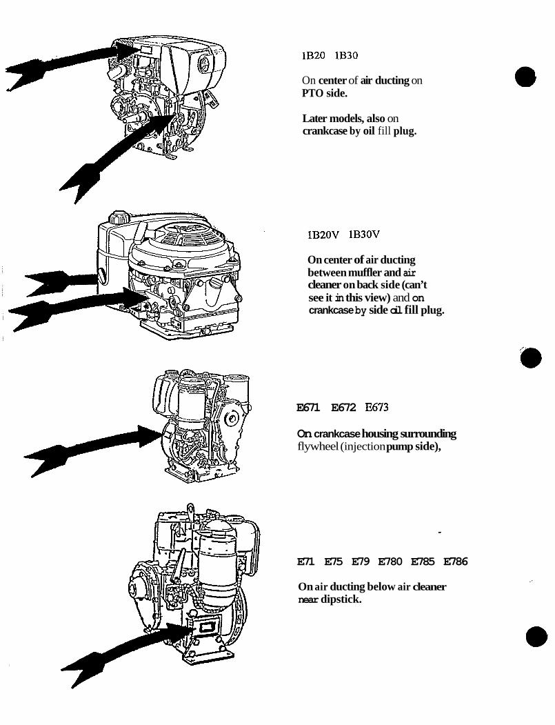
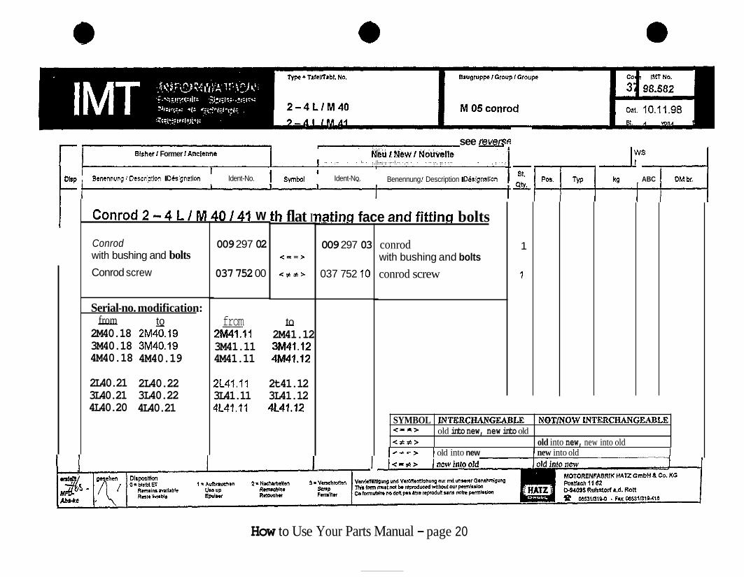
- Note: Use this modification page, found in the back of the parts manual, to determine which parts are not interchangeable between series.
Example: If ordering parts for a 2M4 1.10 (Series 10) from a 2M41.12 (Series 12) parts manual, you must review IMT (Parts Bulletins) numbers; 98.578 and 98.582. Samples follow.
89.487
89.487
89.487
89.488
91.51 3
89.488
91.51 3
89.488
91.51 3
98.578
98.582
98.578
98.582
98.578
98.582
How to Use Your Parts Manual - page 17 98

Blsher I Former I Anclenne
I
Cvlinder head and tehperature
cylinder head temperature switch 180" C interned. piece joint
Modification of series no.: 2-4 M 41.10 to 2-4 M 41.11 2-4 L41.10 to2-4 L41.11
013 175 01 400 328 0 050 278 01 500 010 01
Symbol
witch fl
<==>
Neu I New I Nouvelle
Ident-No.
' 2 - 4 M L
013 175 1 502 686 0
Benennung I Description I DBslgnetion
and 2- 4 L41 C/K
cylinder head temperatur swith 220 O C
- St
S Y
1 1 1 1
- Pas. -
42 43 44
SI
ABC -
SYMBOL INTERCHANGEABLE NOT/NOW INTERCHANGEABLE < = = > < # f > old into new, new into old < # - > old into new new into old
old into new < = # >
old into new, new into old
new into old
DM bf.
How to Use Your Parts Manual - page 18

_-
Bisher / Former / Ancienne h
Neu / New / Nouvelle
1
How to Use Yo* s Manual - page 19 * i
c
SYMBOL < = - > <#??>
r
JNTERCBANGEABLE NOTRYOW INTERCHANGEABLE old into new, new into old
old into new, new into old
see reven Bishef I Former I Anciennc Neu t N w 1 Nouwelle
I I
Bemnnung I Dcscriptlon I DCslgnation Ident-No. Ident-No.
Conrod2=4L/M40/41 w
Conrod with bushing and bolts Conrod screw
Serial-no. modification:
2M40.18 2M40.19 3M40.18 3M40.19 4M40.18 4M40.19
- from to
2L40.21 2L40.22 3L40.21 3L40.22 4L40.20 4L40.21
009 297 02
037 752 00
from
h flat I
< = = >
< * # >
- to 2M7.11 2M41.12 3M41.11 3M41.12 4M41.11 4M41.12
2L41.11 2t41.12 3L41.11 3L41.12 4L41.11 4L41.12
Benennung I Description I Ddslgnallon
iating face and fitting bolts
009 297 03
037 752 10
I
conrod with bushing and bolts
conrod screw
- St.
AYL
1
1
- ABC DM br.
~- ~
> I old into new I new into old I
How to Use Your Parts Manual - page 20

_-
VI
C I%
:
3

IMT PARTS BULLETIN INDEX
SYMBOL
<#=>
<=#>
The old & interchangeable with the new
The new & interchangeable with the old. and
The old is not interchangeable with the new and
The new is not interchangeable with the old.
The old & interchangeable with the new and
The new is not interchangeable with the old.
The new & interchangeable with the old and
The old is not interchangeable with the new.
How to Use Your Parts Manual - page 22

NUMBERING SYSTEM
HATZ identifies all their products as engines, engine accessories, spare parts, and special tools by a - standardized numbering system.
Each item or part is specified by an 8-digit identification number.
Identification Numbers are partitioned into sections as follows:
Engines
Customer spec. lists
- 000 001 ..- 002 999 .. 003 000 ..- 029 999 ..
- = Engines accessories, assemblies, sub-assemblies,
030 000 ..- 599 999 .. 600 000 ..- 699 999 .. = Special tools 950 000 ..- 950 999 .. - - Technical advice
- - . Individual parts
HATZ 8-digit part numbers can be broken down as follows:
ISt 6 digits - - Part Number Part Number Modification Index - Final 2 digits -
Part Number Modification Index (last 2 digits of all HAT2 spare parts numbers)
00 I EXAMPLE P/N 400001
00 = ORIGINAL STATE 01 = FIRST MODIFICATION 02 = SECOND MODIFICATION, ETC.
As each modification is made to the part, the unit digit of the part number is incremented by one.
First, second, third modifications, etc. up to 09 are designed to be interchangeable in most cases therefore are not stated in the obsolete/replacement parts listing.
(00-09 interchangeable) (1 0-19 interchangeable) (20-29 interchangeable)
In case of major modifications to the part, the tenth’s digit of the part number is incremented by one. EXAMPLES: from 0 1 to 10
from 10 to 20
These parts are NOT directly interchangeable.
How to Use Your Parts Manual - page 23 c:Wavc\nurnbcringsys.doc January 17,2000

ar M 13 Soufflerie
Ventilador Ventil at ore
1 (2-7) - Fig.- HAT2 Stuck P / W Bemerk
d I D Notes Qty. Tabl. No. @ No. Ident-No. Tavola N.
2 M
1 1 2
3 4 5 6 7 8
9 ’ 10
11
12 13 14
15 16 17
18 19 20
14
- Note: The spare parts manual section “M” or “A” corresponds with the same section in the repair manual. Sample follows.
00740202 1 01 203701 ....-.- 03562500 2 03552600 1 03598500 1
03552401 1
00959000 1
00989701 0099001 1 50055100 2
50061700 4 50070600 2 50002900 2
50023500 2 03595600 0.. .4 00919800 2
_ _ _ _ _ _ ^
03552600 2 50052600 2
3 M
1
2 1 1
1
1
2
4 2 2
2 0...4
2
2 2
4 M
1
2 1 1
1
1 2
4 2 2
2 0...4
2
2 2
335 mm 33 mm
240 mm,
M 10 x 55 A 10 DIN 137
DIN 7349 105 DIN 128 10
DIN 934-8 M 10
DIN 912-8.8
M 8 x 45 DIN 912-8.8
How to Use Your Parts Manual - page 24
~

Preparatory work: - Take off the exhaust-system capsule (en-
capsulated engines only) and the silencer (muffler); see A 03.00.
Encapsulated engines: - Take off the capsule side panel, air outlet
duct, air guide housing and fan impeller; see M 35.00.
Non-encapsulated engines: - Take off t he cooling air guide. - Take off the hydraulic shutdown device;
- Disconnect the battery. see M 20.00.
Removing: - Mark and disconnect the wiring at the alter-
- Take out screws (I 17/1). - Pull out the fan housing.
nator.
Checking parts: - Check the fan housing sealing strips for
signs of damage; if necessary, attach new sealing strips with adhesive G.
Installing: - Apply a slip agent, e.g. Vaseline, to the
contact faces of the fan housing sealing strips.
- Install the fan housing and check that the sealing strips are correctly positioned.
- Re-assemble the items removed from the engine in the opposite order of work to that described for their removal.
accurately. - Make sure that the Poly-V belt is installed
When connecting cables to the alternator, do not accidentally interchange them; see Fig. 118.
P C I M . 01.97
- Note: Sample.
How to Use Your Parts Manual - page 25, The End. I

P.R.O. KITS
CATALOG
HAT2 DIESEL OF AMERICA, INC. W229 N 1645 WESTWOOD DRIVE
P.O. BOX 258 WAUKESHA, WI 5 3 187-0258
MARCH, 1999

P . R . 0 . KITS CATALOG PARTS REQUIRED FOR OVERHAUL
Crankcase Gasket Sets ..............................
Cylinder Head Gasket Sets ........................
Maintenance Kits .......................................
Emergency Kits ..........................................
Rubber Parts Kits ......................................
Exhaust Capsule Kits .................................
Engine Capsule Kits ..................................
Rebuilt Kits Lower End .............................
Rebuilt Kit Top End ...................................
Capsule Foam Kits ...................................
1
17
32
41
58
63
65
69
73
75
Part#: 000 000 17

1) CRANKCASE GAS
E7 1 -E780
E786
E80-E89
1 D3 0/40/4 1
(ET SETS
~
012 298 00 4
012 299 00 5
012 300 00 6
012 798 01 7
MODEL
Z782/2790
1B20
012 302 00
CRANKCASE GASKETSETS I PAGE
015 542 00 1 16
1B30 015 822 00 I l6
E673LS 012 759 00 1 3
E673 012 297 00 l 2
1D60/80/8 1/90 012 493 11
012 301 00 I E950 1 9
2G30/40 012 280 00 I lo
I l1
El 08/21 08 012 305 00 I l2
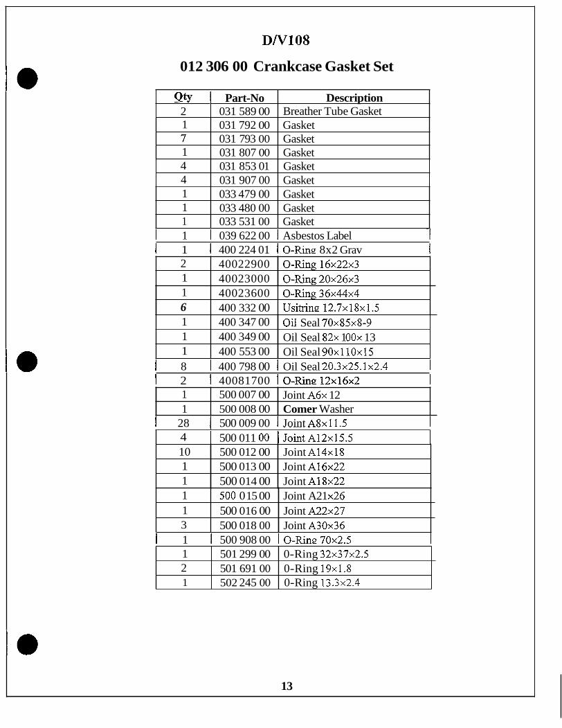
D108N108 012 306 00 I l3
2,3,4L30 012 307 01 I l4
2,3,4L/M40/41 012 309 02

E673
Qty 1
012 297 00 Crankcase Gasket Set
Part-No I Description 032 092 02 1 Gasket
2 1 2
040 713 00 Gasket 400 217 00 0-Ring 4.5x8.1x1.8 400 220 00 0-Ring. 5 x 9 ~ 2 u
2 I 40022300 I O-Ring8x12x2 1 1
~
400 228 00 0-Ring 15x21.4~3,2 400 238 00 O-Ring 74x3
1 1
400 337 00 I Oil Seal 30x47~8 400 342 00 1 Oil Seal 60x75~8
1 5
I 1 I 501 54000 I O-Ring110x116x3 ~
~~
400 863 00 Felt Washer 500 010 00 Joint A10x16
2 500 01 1 00 Joint A12x15.5 1 500 015 00 Joint A21x26 2 500 624 00 Joint A10x13.5 fl 1
2
1 1
502 524 00 502 826 03 Sticker
Oil Seal 40x47~4
1 503 244 00 Seal

E673LS
012 759 00 Crankcase Gasket Set
Qty Part-No Description 1 032 092 02 Gasket 1 039 131 00 Gasket 2 040 713 00 Gasket 1 400 2 17 00 0-Ring 4.5x8.1 x 1.8 2 40022000 O-Ring5x9x2
I 1 I 400 339 00 I Oil Seal 40x52~7 1 1 1 400 342 00 1 Oil Seal 60x75~8 1
5 500 010 00 Joint A10x16 2 500 01 1 00 Joint A12x15.5 1 500 015 00 Joint A 2 M 6 2 500 624 00 Joint A10x13.5 1 501 538 00 0-Ring: 23~29x3
I 1 I 501 540 00 I 0-Ring 110x1 16x3 1 I 1 I 502 524 00 I Oil Seal 40x47~4 1
1 502 826 03 Sticker 1 503 244 00 Seal
3

E71-780
1 2 1
012 298 00 Crankcase Gasket Set
031 502 02 031 684 00 Gasket 031 745 00 Gasket
Gasket f. Fuel Tank I O h I Part-No 1 Descrbtion i
1 1
400 339 00 400 347 00
Oil Seal 40x52~7-8.5 Oil Seal 70x85~8-9
I 1 031 99200 I Gasket 1
2 2
I 2 1 40021700 I O-Ring;4.5x8.1x1.8 1
500 009 00 500 01 1 00
Copper Washer A8 Copper Washer A12
I 2 1 400 223 00 I 0-Ring 8x12~2 1
1
1 2
I 2 1 400 229 00 I 0-Rine 16x22~3 1
501 53800
502 826 03 Sticker
-- 502 229 00 O-Ring 1 0 0 ~ 1 0 8 ~ 4
1 1 1 40023600 I O-Rine36x44x4 1 I 1- I 400338 00 1 Oil Seal 35x47~7-9 1
1 ~~
I 2 I 500-01200 I CotmerWasherA14 I 1 I 500 015 00 I Comer Washer A21 1
~ _ _ ~
1 1 503 244 00 1 Sealing Ring
a
(I
4

E786
012 299 00 Crankcase Gasket Set
2 1
Otv I Part-No 1 DescriDtion i
031 684 00 Gasket 031 745 00 Gasket
1 I 031 502 02 I Gasket f. Fuel Tank
2 1
40022900 O-Ring16x22x3 400338 00 Oil Seal 35x47~7-9
1 1 031 99200 ]-Gasket 1
2 2
2 1 400 217 00 I 0-Ring 4.5x8.1x1.8 1
500 009 00 500 01 1 00
Copper Washer A8 Copper Washer A12
2 I 400223 00 1 O-Ring8x12x2
2 1 1
500 012 00 500 0 15 00 501 538 00 0-Ring: 32~29x3
Copper Washer A14 Copper Washer A2 1
1 1 400 339 00 I o i l Seal 40x52~7-8.5 1
1 1
1 1 400 341 00 I Oil Seal 50x65~8-10 1
502 826 03 Sticker .?? ... -- 503 244 00 Sealing Ring
1 1 400 347 00 I Oil Seal 70x85~8-9 1
1 1 501 542 00 1 0-Ring. 5 x 7 ~ 1 1 1 I 502 229 00 1 0-Ring 100x108~4 1
5

E80-89
012 300 00 Crankcase Gasket Set
6

lD30-41
012 798 01 Crankcase Gasket Set
Qty Part-No Description 1 037 951 00 0-Ring 265x269.4x3.6 2 037 958 00 0-Ring 12x18.3x7.3 2 040 713 00 Gasket 1 040 886 00 Sticker Label 1 050 689 00 Gasket 2 500 011 00 Joint A12x15.5 2 500 016 00 Joint A22x27 2 500 624 00 Joint A10x13.5 1 501 299 00 0-Ring. 3 2 ~ 3 7 ~ 2 . 5
I 1 I 502 245 00 I 0-Ring: 13.3x2.4 1 I I 1 - " 1
1 502 825 01 Silicon Sealer 1 502 826 03, Sticker 1 502 864 00 Joint A24x29 1 503 258 10 Oil Seal 54x70~8 2 503 289 00 0-Ring 2 2 ~ 1,6 3 503 290 00 0-Ring 9.5~2.5
I 2 I 503 29200 I 0-Ring: 50x55~3 1 1 503 304 00 0-Ring 27x2N 1 5033 18 00 0-Ring 1 503 354 00 0-R.h~ 4.7~1.6 1 I 503 497 00 0-Ring 100~2.5 2 503 597 00 0-Ring 20.29x2.62 1 1 503 681 01 Oil Seal 52x80~10
503 63400 2 --
I 1 I 50460400 I 0-Ring18x2
7

lD60-90
012 493 11 Crankcase Gasket Set
Qty 1 2
Part-No Description 037 951 00 0-Ring 265~26.94~3.6 037 958 00 0-Ring 12x18.3x7.3
2 I 500 01600 I Joint A22x27 2 1 1
500 624 00 Joint A10x13.5 501 299 00 0-Ring 32~37~2.5 50224500
1 1 1
1 50335400 - 2 503 597 00 0-m~ 20.29~2.62
502 249 00 0-Ring 123~2.5 502 825 01 Silicon Sealer 502 826 03 Sticker
2 1
u 1
503 292 00 0-Ring 50x55~3 503 304 00 0-Ring 27x2N
8
1 I 503 627 00 Oil Seal 62x90~10 1 50363400 1 1 503 861 00 0-Ring 21x2 1 504 604 00 0-Ring 18x2
- ~ -

E950
Qty 2
012 301 00 Crankcase Gasket Set
Part-No Description 031 684 00 Gasket
1 1
I 1 I 033921 00 1 Gasket I 034 385 00 Gasket 034 387 00 Gasket
2 1
I 1 I 034 445 01 I Gasket f. Blower I ~ ~~ ~ -
400 220 00 0-Ring 5 x 9 ~ 2 40022900 O-Ring16x22x3
I 1 7 2
400 371 00 0-Ring 152.5~157.5~2.5 500 008 00 Copper Washer 500 009 00 Joint A8x11.5 500 011 00 Joint A12x15.5
I 2 I 50001200 I JointA14x18 I 3 4
500 01600 Joint A22x27 500 624 00 Joint A10x13.5
I 1 I 500 82200 1 Oil Seal50x72x8 BBL I 1 1 1
3 1 14701 Oil Seal 64x90~10 501 152 00 50153800 O-Ring23x29x3
Oil Sea1 40x62~7 BBL
I 2 1 501 691 00 I 0-Ring. 19x1.8 I I 1 I 50222900 I 0-Ring. 100x108~4 I I 2 I 502245 00 I 0-Ring 13.3x2.4 I I 1 I 502 481 00 I 10x14~2 I
1 - I 1 1 502 826 03 I Sticker 1 1
9

2 G3 0/4 0
012 280 00 Crankcase Gasket Set
Qty 1 1
Part-No Description 503 362 00 0-Ring 10x3 041 18500 Shiml.O
1 5
041 186 00 Shim 1.4 500 009 00 Joint A8x11.5
-
3 1
1 I 503 112 00 I Oil Seal 38x52~8 1
~~ ~~~
500 01 1 00 500 012 00 Joint A14x18
Joint A12x15.5
1 8
1 ] 503 362 00 I 0-Ring 10x3
50153800 O-Ring23x29x3 502 750 00 0-Ring 14~1.78
10
~~
2 2 503 123 00 Gasket 0.1 1 503 124 00 Gasket 0.2 2 503 125 00 Gasket 0.3 1
503 115 00 ' Gasket Timing Cover
I 503 235 00 I 0-Ring 7 0 ~ 7 5 ~ 3 . 1

782/790
Qty 1 2
012 302 00 Crankcase Gasket Set
Part-No Description Breather Tube Gasket 03 1 589 00
031 907 00 Gasket
1 1 1 2 1
032 118 01 Gasket 032 121 00 Gasket, Sum 032 124 00 Fuel Pum Gasket 032 164 01 Gasket
1 032 168 00 Gasket 032 702 00 Gasket 032 704 00 Gasket 400 224 01 0-Ring 8x2 Gray 40022900 O-Ring16x22x3 400 234 00 0-King: 32x38~3
1 1
v I I 400 236 00 I 0-King 36x44~4 I
1 400 347 00 Oil Seal 70x85~8-9 400 371 00 O-Rine 152.5~157.5~2.5
2 pp-400817 00 1 500 008 00 7 500 009 00
pp 1 Copper Washer Joint A8x11.5
1 1 501 147 01 Oil Seal 64x90~10 -
1 1 501 299 00 0-Ring 3 2 ~ 3 7 ~ 2 . 5
2 1
1 1 - "
1 1 501 538 00 1 0-Ring 23x29~3
502 245 00 0-Ring 13.3x2.4 502 826 03 Sticker 2
1 1 I 501 691 00 I 0-Ring 19x13 1
11

E/Zl08
012 305 00 Crankcase Gasket Set
1 1
2 1 I
4
400 349 00 Oil Seal 82x lOOx 13 400 553 00 Oil Seal 9Ox 1 1 Ox 15
40081700 O-Ring12x16x2 500 007 00 Joint A6x 12 500 008 00 Copper Washer
400 798 00 0-Ring 20.3~25.1~2.4
1 1 3 1 2 I
12
500 0 15 00 Joint A2 1 x26 500 016 00 Joint A22x27 500 018 00 Joint A30x36 500 908 00 0-Ring 70~2.5 501 691 00 0-Ring 19x13 502 245 00 0-Ring 13.3x2.4
DN108
012 306 00 Crankcase Gasket Set
Qty 1 Part-No 2 1 031 589 00
Description Breather Tube Gasket
1 7 1
031 792 00 Gasket 031 793 00 Gasket 031 807 00 Gasket
4 4
I 1 I 039 622 00 1 Asbestos Label -1
031 853 01 Gasket 031 907 00 Gasket
I 1 1 400 224 01 I 0-Ring 8x2 Grav 1
1 1 1
033 479 00 Gasket 033 480 00 Gasket 033 531 00 Gasket
2 1
~
40022900 O-Ring16x22x3 40023000 O-Ring2Ox26x3
I 8 I 400 798 00 I Oil Seal 20.3x25.1x2.4 1
1 6
I 2 I 40081700 1 O-Ring:12x16x2 1
40023600 O-Ring36x44x4 400 332 00 Usitring 12.7x18x1.5
1 1 1
I 28 1 500 009 00 I Joint A8x11.5 1
400 347 00 400 349 00 400 553 00
Oil Seal 70x85~8-9 Oil Seal 82x 1 OOx 13 Oil Seal 90x110~15
1 ~ ____. ~ ~.
4 I 500 011 00 1 JointA12x15.5
1 1
500 007 00 500 008 00 Comer Washer
Joint A6x 12
10 1 1
1 1 I 500 908 00 10-Ring70x2.5 1
500 012 00 Joint A14x18 500 013 00 Joint A16x22 500 014 00 Joint A18x22
1 1 3
13
~
500 0 15 00 Joint A21 x26 500 016 00 Joint A22x27 500 018 00 Joint A30x36
1 2 1
~
501 299 00 0-Ring 3 2 ~ 3 7 ~ 2 . 5 501 691 00 0-Ring 19x1.8 502 245 00 0-Ring 13.3x2.4

2-4L30
012 307 01 Crankcase Gasket Set
1 1
I Otv 1 Part-No 1 Descrintion . i
034 620 00 Gasket 034 659 00 Gasket
L 8 I 031 684 00 I Gasket 1
1 1
035 681 00 Gasket 035 870 00 Rubber Ring
I 1 I 035 50601 1 Gasket. Sealcarrier 1
4 3 2
I 1 I 035 680 00 I Gasket, Pump 1
500 014 00 Joint A18x22 500 016 00 Joint A22x27 501 290 00 Gasket Oil Filler
1 1
I 1 ~ I 036 14001 I Gasket. Side Cover 1
502 245 00 0-Ring13.3x2.4 502 825 01 Silicon Sealer
I 2 I 400 223 00 I 0-Ring. 8 x 1 2 ~ 2 1
13 I 3 I 50001200 I JointA14x18 1
1 1 501 291 00 I Oil Seal B55x70x8
r I-- 1502 82603 I Sticker I
14
.-
I

012 309 02 Crankcase Gasket Set
1 1
I 4 I 03969400 I Joint
400 217 00 0-Ring 4.5x8.1x1.8 400 223 00 0-Ring 8~ 12x2
1
1 8 9 5
I 1 I 041 027 00 I Washer f. Belt Tens. i
400 817 00 0-Ring 12~16x2 500 009 00 Joint A8x11.5 500 01 1 00 500 012 00 Joint A14x18
Joint A12x15.5
1 1 2
501 324 01 O-Ring 53.57~3.53 501 399 00 0-Ring 23.3x2.4 501 422 00 O-Rine 24.8~1.5
1 2 I 500 01400 1 JztA18x22
1 1
I 4 I 50001600 I JointA22x27 1
502 025 02 0-Ring 3.0x1.6 502 194 00 0-Ring 12x2
I 3 I 50062400 I JointAlOx13.5 1
1 2
I 2 I 501 304 00 IO-Rine 16.3~2.4~21.1 1
503 244 00 Seal 503 267 00 0-Ring 9 .7~1
I 2 I 501 307 00 I 0-Ring 42~2.5 1
I 6 I 501 629 00 I JointA8x14 1
I 1 I 502631 00 10-Ring I 1 I 502 825 01 I SiIiconSealer 1
1 1 . 502 826 03 I Sticker 1
I 1 I 503 467 00 I 0-Ring 7.5x2.5
15

lB20
015 542 00 Crankcase Gasket Set
Qty 1
Part-No Description 015 837 00 Breather Tube
I 1 040 980 00 I Sealing. Striu 331 Smm 1
2 1
I 1 400 337 00 I Oil Seal 30x47~8 1 1 501 629 00 Joint A8x14 504 232 00 Oil Seal 40x55~10
Qty Part-No 1 041 126 00 1 400 337 00
1 1 I 504 403 00 1 0-Ring: 8x1.5 1
Description Sealing Strip 4 19mm Oil Seal 30x47~8
I 2 I 504 698 00 1 Joint A8x11.5
2 1
13330
015 823 00 Crankcase Gasket Set
501 629 00 Joint A8x14 504 403 00 O-Ring 8~1.5
1 2
504 6 18 00 Rubber Sleeve 504 698 00 Joint A8x11.5
~~ ~
1 1 404 498 00 1 Oil Seal 42x55~10 1
16

I 2) CYLINDER HEAD GASKET SETS
E51673 I 009 106 10 1 18 I
MODEL
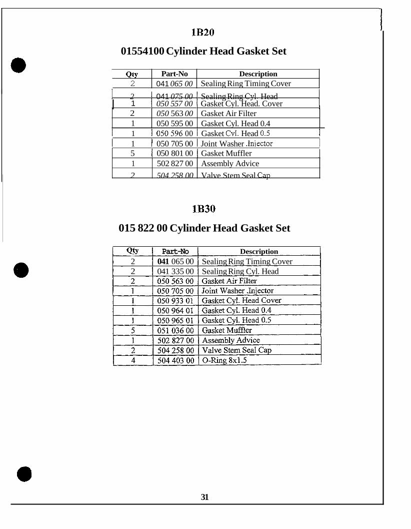
1B20
1B30
E7 1 I75
CYLINDER HEAD GASKETSETS PAGE
015 541 00 31
015 822 00 31
003 394 -10
E786
E80/85
I l8 I
003 589 10 19
003 312 11 20
E79E780
E88/89
1 D3 0140
003 552 11
003 333 10 21
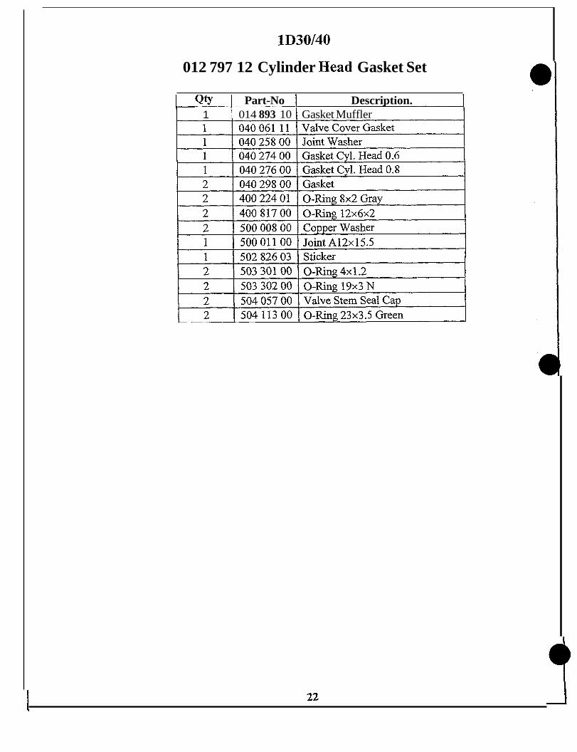
012 797 12 22
I l9 I
1D3 1
1D41
015 225 00 23
015 051 01 23 . . .
1D60
ID80
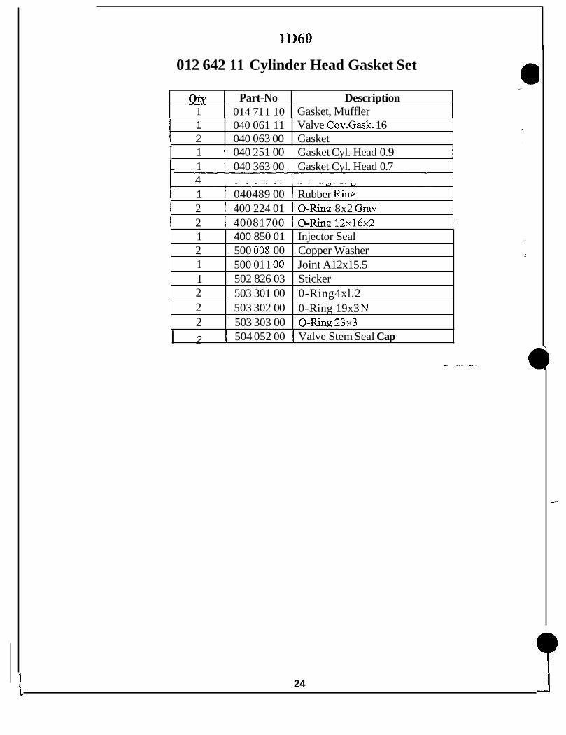
012 642 11 24
012 492 11 25
I I 1
1D81
E950
2G3O
2G40
2788-2790
E/Z/D/V108
015 17800 26
007 037 10 27
012 281 00 28
012 477 00 28
005 695 10 29
005 582 11 29
2/3/4L3 0 I 009 919 00 I 30 I 2/3/4L/M40/4 1 I 009 922 02 I 30 I
17

E673
Qty 1
009 106 10 Cylinder Head Gasket Set
Part-No Description 012 846 00 Gasket Oil Bath Air Cleaner
1 1 1
012 861 00 Gasket Muffler 032 089 02 Gasket 035 81800 Gasket Cvl. Head 0.4
1 I 035 820 00 I Gasket Cyl. Head 0.6 2 1
400 81700 O-Kng12x16x2 500 01 1 00 Joint A12x15.5
I 1 I 501 543 00 1 0-Rina7.5x10.5x1.5 1 1 I 501 542 00 0-Ring 5 x 7 ~ 1
E71/75
1 1 4
003 394 10 Cylinder head Gasket Set
502 826 03 Sticker 502 827 00 Assembly Advice 502 880 00 0-Ring. 17x3
Qty 1
Part-No Description 01 1 539 00 Gasket Muffler
1 1 1
1 502 826 03 Sticker 1 502 827 00 Assembly Advice
01 1 540 00 031 605 00 Joint Washer 031 735 00
Gasket Kit
Gasket Cyl. Head 0.5
18
1 1 031 737 00 1 I 031 741 00
Gasket Cyl. Head 0.7 Gasket

E79E780
012 858 00 031 729 01
003 552 11 Cylinder Head Gasket Set
Gasket Muffler. Gasket
1 031 729 01 1 031 741 00
1 1
Gasket Muffler -7
032 038 00 Gasket Cyl. Head 0.7 032 040 00 Gasket Cyl. Head 0.9
Gasket Kit I
1 032 042 00 1 I 032 288 00
Gasket Gasket
Gasket Joint Washer 1.0
I - -~~~
1 1 031 974 00 I Gasket. Cvl. Head 0.5 I 031 976 00 I Gasket Cvl. Head 0.7 ~ -7 032 288 00 I Joint Washer 1.0 I 039 402 01 I Gasket Application J
1 1 I 1
501 542 00 o - s n g 507cll 501 629 00 Joint A81314 502 826 03 Sticker 502 827 00 Assemblv Advice
E785E786
003 589 10 Cylinder Head Gasket Set
I 1 I 01 1 587 00 I Gasket Oil Bath Air Cleaner I I 1
1 4 400 223 00 400 232 00 400 817 00 400 850 01 500 009 00 501 542 00 501 629 00 502 826 03 502 827 00
0-Ring 80 1202 0-Ring 3 104Kl4.5 0-Ring 120 l a 2 Injector Seal Joint A80 1 1 -5
Joint A80 14 Sticker
0-Ring 507Cl1
-~
Assembly Advice
19

ES0/85
003 312 11 Cylinder Head Set
1 032 288 00 Joint Washer 1,0 2 400 216 00 0-Ring 2.5174.901.2 4
2 500 009 00 Joint A80 1 1.5 1 500 020 01 Gasket 26SP-AF
20

E88/89
Qty Part-No Description 1 01 1 587 00 Gasket Oil Bath Air Cleaner/F
003 333 10 Cylinder Head Gasket Set
1 2
0 12 860 00 Gasket Muffler 031 487 00 Joint Washer
I I 0 12 847 00 I Gasket Air Intake Tube 1
1 1
03 1 597 01 Gasket Cover 031 605 00 Joint Washer
1 1 I 031 589 00 I Breather Tube Gasket 1
4 2 2 2 2
I 1 I 03 1 593 00 I Gasket Cyl. Head 0.7
400 223 00 0-Ring 8 x 1 2 ~ 2 400225 00 O-Ringllx19x4 400 235 00 0-Ring 35x47~6 400 817 00 0-Ring 12x16~2 500 009 00 Joint A8x11.5
1 ~~~
1 1 1 032 288 00 I Joint Washer 1.0 I 1 1 032 682 00 I Gasket Cvl. Head 0.5 1 I 2 1 400 216 00 I 0-Ring 2.5x4.9x1.2 1
I 1 I 50282603 I Sticker 1 I 1 I 502 827 00 I Assembly Advice 1
21
lD30/40
012 797 12 Cylinder Head Gasket Set
Qty Part-No I Description. 014 893 10 I Gasket Muffler 1

9
Qty 1 1
lD31
015 225 00 Cylinder Head Gasket Set
Part-No Description 014 893 10 Gasket Muffler 040 061 1 1 Valve Cover Gasket
1 2 1 1
040 258 00 Joint Washer 040 298 00 Gasket 041 010 00 Gasket Cyl. Head 0.6 041 012 00 Gasket Cvl. Head 0.8
I I I
~
2 2
I 2 1 400 224 01 I 0-Ring: 8x2 Grav I ~~
400 817 00 0-Ring 12x16~2 500 008 00 Copper Washer
Qty Part-No 1 014 893 10 1 040 061 1 1
I 1 I 500 011 00 1 Joint A12x15.5 I
Description Gasket Mufner Valve Cover Gasket
I
lD41
015 051 01 Cylinder Head Gasket Set
1 I 040 258 00 I Joint Washer 1
2 503 302 00 0-Ring 19x3 N 2 504 057 00 Valve Stem Seal Cap
I 2 I 504 113 00 1 0-Ring 23~3.5 Green I
23 L
lD60
Qty 1
012 642 11 Cylinder Head Gasket Set
Part-No Description ' 014 71 1 10 Gasket, Muffler
1 2
040 061 1 1 040 063 00 Gasket
Valve Cov.Gask. 16
I 1 I 040 251 00 I Gasket Cyl. Head 0.9 i
1 2 1 1 2 2 2
- 1 040 363 00 Gasket Cyl. Head 0.7 4
400 850 01 Injector Seal 500 008 00 Copper Washer 500 01 1 00 Joint A12x15.5 502 826 03 Sticker 503 301 00 0-Ring4xl.2 503 302 00 0-Ring 19x3 N 503 303 00 O-Ring 23x3
I 1 I 040489 00 I Rubber Ring 1 I 2 I 400 224 01 I 0-Ring 8x2 Gray 1 I 2 I 40081700 IO-Ring: 12x16~2 1
I 2 I 504 052 00 { Valve Stem Seal Cap
. . . . . _. .
24

t lD80
Qty 1 1
012 492 11 Cylinder Head Gasket Set
Part-No Description .
014 71 1 10 040 027 00
Gasket, Muffler Gasket. Cyl. Head 0.9
2 1
~~
1 1 040 061 11 1 Valve Cover Gasket 040 063 00 Gasket 040 365 00 Gasket Cyl. Head 0.7
1 1 4 2
1 2
~ -- 040 366 00 040 489 00 Rubber Ring 040 845 00 Sealing Ring 400 224 01
400 850 01 Joint
Gasket Cyl. Head 0.8
0-Ring 8x2 Gray 40081700 O-Ring12~16~2
2 1 1
~~
500 008 00 Copper Washer 500 01 1 00 Joint A12x15.5 502 826 03 Sticker
I 2 1 503 303 00 1 0-Ring.23~3 7
2 I 503 301 00 2 1 503 302 00
I Y I
0-Ring 4x1.2 0-Ring 19x3 N
i 2 I 504 052 00 I Valve Stem Seal Cap I
25

lD81
015 178 00 Cylinder Head Gasket Set
Qty 1
Part-No [ Description 0 14 29 1 00 I Gasket Muffler
1 1 2
1 1 1 040258 00 I Jointwasher 1
040 027 00 040 061 11 Valve CoverGasket 040 063 00 Gasket
Gasket Cyl. Head 0.9
I 1 I 040 365 00 I Gasket Cvl. Head0.7 1 1 04036600 1 040 489 00 4 I 040 845 00
- 1 Rubber Ring Sealing Ring
2 2 2 1
I 1 I 502 82603 I Sticker 1
400 224 01 0-Ring 8x2 Gray 40081700 O-Ring12x16x2 500 008 00 Copper Washer 500 01 1 00 Joint A12x15.5
1 2
502 827 00 Assembly Advice 503 301 00 0-Ring4x1.2
2 2
26
503 302 00 503 303 00 0-Ring 23x3
0-Ring 19x3 N
2 2
504 052 00 504 598 00
Valve Stem Seal Cap Sealing Cyl. Screw

E950
007 037 10 Cylinder Head Gasket Sets
Qty Part-No I Description 1 012 858 00 I Gasket Muffler
r
1 1 1 032 288 00 I Joint Washer 1.0 I 1 1 033 941 00 I Gasket
033 668 00 I Gasket Cyl. Head 0.6 1
I 1 034767 00 1 Gasket 2 400 228 00 0-Ring 15x21.4x3.2 1 400 558 00 Joint 1 400 734 00 Rubber Ring 012-1 1 400 815 00 0-Ring 8 ~ 1 3 ~ 2 . 5 3 500 009 00 Joint A8x11.5 2 50154200 O-Ring5x7xI
1 1 502 827 00 Assembly Advice
27

2G30
012 281 00 Cylinder Head Gasket Set
Qty 1
Part-No Description 012 855 00 Gasket Muffler
I 1 I 032288 00 I Jointwasher 1.1 ~ -1 1 1
037 819 00 Gasket Cyl. Head 0.7 037 935 00 Gasket Cyl. Head 0.6
1 1 1 03783902 I Gasket ~ ~~ 1 1 2
400 850 01 Injector Seal 500 009 00 Joint A8x11.5
I 1 I 500 016 00 1 Joint A22x27 1 2 1 1
501 629 00 Joint A8x14 502 084 00 0-Ring 32x3 502 826 03 Sticker
I 1 1 502 827 00 I Assembly Advice 1
Qty 1 1
I 1 I 502 901 00 1 Joint 38x3 1
Part-No Description 012 855 00 Gasket Muffler 032 288 00 Joint Washer 1.0
I 1 I 502 902 00 I 0-Ring 115.6~121~3.1 1
1 2
1 2 1 503 131 00 I Joint A6x10 1
502 902 00 0-Ring 115.6~121~3.1 503 13 1 00
I
Joint A6x10
2G40
012 477 00 Cylinder Head Gasket Set
I 1 I 03783902 I Gasket I
28

2788-2790 I 005 695 10 Cylinder Head Gasket Set
I
3 500 009 00 Joint A8x 1 I .5 2 502 580 00 0-Ring 17x3 1 502 826 03 Sticker 1 502 827 00 Assembly Advice
005 582 11 Cylinder Head Gasket Set
I Qty I Part-NO { Description 2 031 839 01 Gasket 1 03 1 847 01 Gasket, Valve Cover 1 031 923 00 Gasket 1 1 032 300 00 I Gasket 1 1 032 923 00 Gasket 0,6 1 032 924 00 Gasket 0,s 1 034 771 00 Gasket 4 400 228 00 O-Ring 15~21.4~3.2 2 400 555 00 Valve Stem Seal Cap 1 400 558 00 Joint 3 500 009 00 Joint A8x 1 1.5 1 500 024 01 Gasket 5OSP-AF 1 1 502 827 00 1 Assembly Advice
29

2 L3 0/3 L3 0 /4 L3 0
009 919 00 Cylinder Head Gasket Set
Qty 2
Part-NO Description 034 615 01 Air Intake Gasket
I 1 I 034699 00 I Cover Gasket ~ - 1 1 1 2 1
035 590 00 Gasket Cyl. Head 0.9 035 592 00 Gasket Cyl. Head 1.1 400 228 00 0-Ring 15x21.4x3.2 400 850 01 Injector Seal
1 2
500 008 00 Copper Washer 500 009 00 Joint A8x11.5
2 1
2-4MlL40/41
009 922 02 Cylinder Head Gasket Sets
502 580 00 0-Ring 17x3 502 826 03 Sticker
1 2
1 1 I 03624402 I Gasket 1
502 827 00 Assembly Advice 502 881 00 0-Ring 15x3.2
036 260 01 036 262 01 040 857 00 Hose 7x10~10 041 073 00 Joint
1 400 850 01 Injector Seal
Gasket Cyl. Head 0.8 Gasket Cyl. Head 1.0
Qty 1
Part-NO Description 012 845 01 Gasket. Exhaust Man.
1 2 1 1
500 008 00 Copper Washer 500 009 00 Joint A8x11.5 501 323 00 NylockNut 502 249 00 0-Ring 123~2.5
0
1 1
30
502 826 03 Sticker 502 827 00 Assemblv Advice
2 2 4
502 848 00 502 880 00 0-Ring 17x3 502 881 00 0-Ring 15~3.2
Valve Stem Seal
lB20
01554100 Cylinder Head Gasket Set
QtY 2
Part-No Description 041 065 00 Sealing Ring Timing Cover
I 2 I 041 075 00 I Sealing Ring Cyl. Head I 2 1
I I 050 557 00 I Gasket Cyl. Head. Cover 1 1 050 563 00 Gasket Air Filter 050 595 00 Gasket Cyl. Head 0.4
1 502 827 00 Assembly Advice L 2 504 258 00 Valve Stem Seal Cap
I 1 I 050-596 00 1 Gasket Cvl. Head 0.5 1 I 1 1 050 705 00 I Joint Washer .Iniector I
5 I 050 801 00 1 Gasket Muffler 1
lB30
015 822 00 Cylinder Head Gasket Set
Bty Part-No 1 Description 2 041 065 00 Sealing Ring Timing Cover 2 041 335 00 Sealing Ring Cyl. Head
31

3) MAINTENANCE KITS
E7 1-780
E786
E88/89
~ ~~ ~~
MODEL I MAINTENANCE KITS I PAGE
009 613 02 33
009 614 02 34
009 616 02 34
015 543 00 I 1B20
4wM40/4 1
I 40 015 824 00 I 1B30
I 39 012 033 04
E5/673 I 009 612 02 I 33
1D30-41 I 012 799 10 I 35
012494 10 I 1D60-90
lD60C-81C 1 012 929 10
009 617 01 I E950
1 37 012 282 02 I 2G3 0140
278 8-2790 I 009 618 01 I 37
2LM40/4 1 I 009 871 04 I 38
I 38 009 915 04 I 3 L/M40/4 1

E673
Qty
009 612 02 Maintenance Kit
Part-No I Description
3 2 7 2
I 1 I 031 G 7 0 3 I Oil Drain Plug R1-2 i
032 089 02 Gasket 400 894 01 Fuel Filter 500 015 00 Joint A21x26 500 035 00 Locking Washer
I I 03 1 73 1 00 I Hexagon Nut 2
Qty 1 2
Part-No Description 006 321 01 Oil Fill Cap 031 502 02 Gasket Fuel Tank
I 2 1 500 234 00 I Hexagon Nut M 8x1 1
1 031 506 00 Disc & 1
E71-780
009 613 02 Maintenance Kit
2 3 2 4 7 2
031 73 1 00 Hexagon Nut 031 741 00 Gasket 400 438 00 Filter Element 500 012 00 Joint A14x18 500 015 00 Joint A21x26 500 232 00 Hexagon Nut
4 6
500 627 00 501 629 00 Joint A8x14
All, Scr.M 6x10
33

E786
009 614 02 Maintenance Kit
1 2 1
I om I Part40 I Descrbtion 1 006 321 01 Oil Fill Cap 03 1 502 02 Gasket Fuel Tank 031 506 00 Disc
2 3
I
1 I 03 1 691 03 1 Oil Drain Plug R1-2 1 03 1 73 1 00 Hexagon Nut 032 042 00 Gasket
7 2 4 6
I 2 I 400 438 00 I Filter Element 1
500 0 15 00 JointA21 x26 500 232 00 Hexagon Nut 500 627 00 All. Scr. M6x 10 501 629 00 Joint A8x14
1 4 I 50001200 I JointA14x18 1
Qty Part-No 1 005 623 00
Description Oil Fill Cap
2 2 1
03 1 490 00 Lock Nut 03 1 502 02 Gasket Fuel Tank 031 506 00 Disc
1
1 3 I 03 1 597 01 I Gasket Cover 1 1 2
03 1 691 03 400 438 00 Filter Element
Oil Drain Plug R1-2
1--4p1?00012 00 I Joint A14x18 1
34

1D30-41
4 2
012 799 10 Maintenance Kit
0 14 800 00 Supra Oil Filter 03 1 73 1 00 Hexagon Nut
[ Qty 1 Part-No I Description
2 2 4 1 1
040 301 00 Air Filter 400 894 01 Fuel Filter 500 016 00 Joint A22x27 501 404 00 Drain-Plug 50329200 O-Ring50x55x3
I 3 I 040 06111 1 Valve Cover Gasket 1
lD60-90
012 494 10 Maintenance Kit
_. .
35

lD60C-lD81C
4 2
012 929 10 Maintenance Kit
014 800 00 Supra Oil Filter 014 930 00 Air Filter 1D60/81
1 Qty 1 Part-No I Description
3 2
040 061 1 1 400 894 01 Fuel Filter
Valve Cover Gasket 2 I 031 731 00 I HexagonNut
4 500 014 00 Joint A18x22 , 1 4
500 442 00 Closing Screw M18xl.5 500 812 00 Spring Washer A6
I 2 I 501 708 00 I All.Scr.M6x25
Qty 1 2
1 I 503 292 00 I 0-Ring 50x55~3 1
Part-No Description 006 321 01 Oil Fill Cap 03 1 490 00 Lock Nut
E950
009 617 01 Maintenance Kit
1 1 4
. 2 4 1
034 767 00 Gasket 035 697 00 Pressure Spring 400 38 1 00 400 894 01 Fuel Filter 500 0 16 00 500 444 00
Oil Filter
Joint A22x27 Closing Screw AM22x 1.5
I 1 I 033 659 01 1 Pressure SDring: 1 1 2 1 033941 00 I Gasket I
1 1 I 501 542 00 I 0-Ring 5 x 7 ~ 1 1
36

2630/40
012 282 02 Maintenance Kit
Qty 1
e
Part-No Description 006 321 01 Oil Fill CaD
2 4
I 2 1 031 731 00 I HexanonNut 1 400 894 01 Fuel Filter 500 012 00 Joint A14x18
4 4
I 8 I 501 629 00 I Joint A8x14 I 502 902 00 0-Ring 115.6~121~3.1 503 028 00 Oil Filter
Qty 1
I 1 I 503 11000 1 DrainPlugM14x1.5 1
Part-No Description 006 321 01 Oil Fill CaD
2788-790
009 618 01 Maintenance Kit
4 2 1
032 162 12 Valve Cover Gasket 400 073 00 Filter Element 400 284 00 Hex. Nut M8
I 2 I 031 49000 I LockNut I
1 4
I 2 I031 88401 I Gasket I
490 365 00 Packing Rig 500 012 00 Joint A14x18
4 1 5 1
I 4 I 400 381 00 I Oil Filter 2788/790 1
500 016 00 Joint ~ 2 2 x 2 7 500 444 00 Clos. Screw AM22x1.5 500 627 00 All. Scr. M6x10 500 629 00 Disc B8.4
1 37

2L/M40/4 1
009 871 04 Maintenance Kit
. Qty Part-No Description 2 009 529 00 Air Filter L&M
03 1 490 00 036 476 00
Lock Nut Sealin2 StriD v
2 I 400 653 00 I Oil Filter L&M 1 4 4
500 014 00 Joint A18x22 500 016 00 Joint A22x27
I 1 I 500 442 00 I Clos.Screw M18x1.5 I
Qty 2
I 4 I 503 356 00 I Combi Screw M6x 16
Part-No I Description 009 529 00 1 Air Filter L&M
3L/M40/4 1
009 915 04 Maintenance Kit
p 4 4
031 490 00 LockNut 037 698 00 Sealing Strip 400 653 00 Oil Filter L&M 500 014 00 Joint A18x22 500 0 16 00 Joint A22x27
I 4 I 503 356 00 I Combi Screw M6x16 I
38 I

4L/M40/41
012 033 04 Maintenance Kit
- Qty Part-No Description 4 009 529 00 Air Filter L&M 2 03 1 490 00 Lock Nut 2 036 476 00 Sealing. StriD 2 400 653 00 Oil Filter L&M 4 500 014 00 Joint A18x22
I 4 I 500 016 00 I Joint A22x27 1 1 500 442 00 Clos. Screw M18x1.5 4 501 323 00 NylockNut 1 501 404 00 Drain Plug 4 502 249 00 0-Ring 123~2.5 1 502 5 15 00 Fuel Filter Element 2 503 170 00 Fuel Prefilter
I ~ ~ ~ -~~
4 1 503 356 00 1 Combi Screw M6x16
39

lB20
Qty 4 2
015 543 00 Maintenance Kit ~~ ~
Part-No Description 050 557 00 Gasket Cyl. Head Cover 503 580 00 Grub Screw M8x10
2 2
I 1 I 503 73 1 00 1 Drain Plug M 22~1 .5 504 260 00 504 405 00 Fuel Filter
Air Filter Element
Qty 4
I 4 I 5 0 4 6 9 8 0 I JointA22x27
Part-No Description 050 933 01 Gasket Cvl. Head Cover
lB30
015 824 00 Maintenance Kit
1 2
503 73 1 00 Drain Plug M 22x 1.5 504 260 00 Air Filter Element
I 2 I 503 580 00 I Grub ScrewM8xlO 1
I 2 I 504 405 00 I Fuel Filter I 1 4 I 504 698 00 I Joint A22x27 1
40

4) EMERGENCY KITS
E5/673
E7 1-75
009 656 03 43
009 657 04 43
2G40
2788-2790
~~~~~- ~ -
.012 778 01 51
009 665 03 51
MODEL I EMERGENCY KITS 1 PAGE
1B20 I 015 544 00 I 57
lB30 015 825 00 1 57
I 1 44 E79 009 658 04
E780 I 009 659 04 I 44
I 009 659 04 I 45 E786
1 D3 0/40 012801 11 I 45
1D31 015 226 00 I 46
ID41 015 052 01 I 46
1D60 I 47 012 643 11
1D60C 012930 11 I 47
1D80 012495 11 I 48
ID81 I 48 015 084 00
1D80C I 49 012931 11
1D81C I 49 015 085 00
E950 009 664 03 I 50
2G3O 012 283 03
41

2/3/4M40 012 262 01 52
2/3/4M4 1 015 442 00 53
2L40C 012 057 01 54
2L4 1 C 015 441 00 54
3/4L40C 009 872 02 55
3/4L4 1 C 015 443 00 56

E5J673
009 656 03 Emergency Kit
Qty I 1
Part-No Description .
007 363 00 Closing Plug 009 106 10 Gasket Set Cvl. Head E5/673 037 423 00 Fuel Hose 7/1000 037 663 00 Washer 8.4x17x1.5 400 031 00 Joint Washer 400 046 00 Nozzle 400 326 1 1 Car, B30 Fuel Tank
1 4
I 1 1 400 995 00 I Rain Protection CaD 1 490 375 00 I Packing Ring 500 234 00 I Hexagon Nut M8x 1
1 003 394 10 Gasket Set Cyl. Head E71/75 1 007 363 00 Closing Plug 1 008 055 00 Vent Valve 4 031 71700 Disc 2 03 1 71 8 00 Collar Nut
t
1 2 I 501 444 00 I Hexagon Nut M6 1
1
E71fE75
036 934 00 Fuel Pipe LW 7x360
009 657 04 Emergency Kit
2 034 580 00
[ Qty I Part-No I Description 1
Collar Nut
1 400 046 00 Nozzle 1 400 327 01 Cap Fuel Tank 1 400 995 00 Rain Protection Cap 1 490 375 00 Packing Ring
1
I 1 I 040 897 00 I Fuel Hose 4.5~530 1
1 2 I 500 229 00 I Hexagon Nut M8
43

E79
Qty 1 1
009 658 04 Emergency Kit
Part-No Description 003 552 11 007 363 00 Closing Plug
Gasket Set Cyl Head E79/780
1 4 2
008 055 00 Vent Valve 031 71700 Disc 03 1 718 00 Collar Nut
1 2 I 034 580 00 I Collar Nut 1
1 1 1 1
I 1 I 03693400 1 FuelHose7x360 1
400 046 00 Nozzle 400 327 01 400 404 00 490 196 00 Packing Ring
Cap 340 Fuel Tank Rain Protection Cap
I 1 1 040 897 00 I Fuel Hose 4.5~580 1
I 2 I 500 229 00 I HexagonNut M8 1
I 1- I 400 030 00 I Joint Washer 1
I 2 1 501 444 00 1 Hexagon Nut M6 1
- Qty Part-No I Description 1 003 552 11 Gask.S.Cyl.H.79/780 1 00736300 1 008 055 00 Vent Valve --
-
2 2 1 1
~
03 1 71 8 00 Collar Nut 034 580 00 Collar Nut 040 897 00 Fuel Hose 4,5x580 036 934 00 Fuel Hose 7x360
E780
009 659 04 Emergency Kit
1 [ 40004600 1 I 400 327 01
Nozzle CaD B40.Fuel Tank
I 4- 1-031 717 00 I Disc I
1 2 2
490 380 00 Packing Ring 500 229 00 501 444 00
Hexagon Nut M8 Hexagon Nut M6
1 I I
{ 400 030 00 I Joint Washer 1
I 1- 1200 404 00 I Rain Protection Cap I
a
44 I

E786
Qty 1
012 010 03 Emergency Kit
Part-No Description 003 589 10 Gasket Set Cyl. Hd.785/786
1 1 4 ’
007 363 00 Closing Plug 008 055 00 Vent Valve 03171700 Disc
2 2 1 1
f 1
031 830 00 Collar Nut 031 873 01 Collar Nut 040 897 00 036 934 00
Fuel Hose 4.5~580 Fuel Hose 7x360
1 I 400 327 01 I Cap B40 Fuel Tank 1 1 1 400 367 00 Rain Protection Cap 1 490 380 00 Packing Ring 2 500 028 00 Spring Washer 2 500 229 00 Hexagon Nut M8
- 2 501 444 00 Hexagon Nut M6 1 502 576 10 Nozzle
Qty 1 1 1 1 2 1
1 D30/40
012 801 11 Emergency Kits
Part-No Description 008 055 00 Vent Valve 012 797 12 Gasket Set Cyl. Hd. 036 734 00 Fuel Hose 7x510 400 327 01 Cap B40.Fuel Tank 503 470 00 Circlip As 24~1.75 503 832 00 Nozzle DLLA 170P260
1 1
039 020 00 Fuel Pipe 037 422 00 Fuel Pipe
I 1 I 013 083 00 1 Close. Plug I
45

lD31
1 1
015 226 00 Emergency Kit
013 083 00 Closing Plug 015 225 00 Gasket Set Cyl. Hd.lD31 1
1 Qty 1 Part-No I Description .
1 1
I 1 I 008 055 00 I Vent Valve i
037 422 00 1 Fuel Hose 4.5~1000 039 020 00 I Fuel PiDe
1 1 1
1 1 I 036 734 00 I Fuel Hose 7x510 1
008 055 00 Vent Valve 013 083 00 Closing Plug 015 051 01 Gasket Set Cvl. Head 1D41
1
I 1 I 400 327 01 I Cax, F. Fuel Tank €340 1
037 422 00 Fuel Hose 4.5~1000
I 2 1 503 470 00 1 CircliD 24~1.75 1
1 039 020 00 1 I 400 327 01
I 1 I 504 154 00 I Nozzle DLLA 160P469 1
Fuel Pipe CaD Fuel Tank B40
lD41
015 052 01 Emergency Kit
1 1 504 154 00
1 Qty Part-No ] Description 1
Nozzle DLLA 160P469
I I - I 1
I 1 I 036 734 00 1 Fuel Hose 7x510 1
46

lD60
012 643 11 Emergency Kit
Qty Part-No Description 1 008 055 00 Vent Valve 1 I 012 642 11 I Gasket Set Cyl. Hd.lD60
- 1 013 083 00 Closing Plug 1 036 736 00 Fuel Hose 7x600
I 2 1 503 470 00 I CircliD 24~1.75 1 1 1 I 503 834 00 I Nozzle DLLA 160s 1 181 1 I 1 I 503 858 01 I CaD Fuel Tank B60 1
1 037 422 00 Fuel Hose 4.5~1000 1 039 020 00 Fuel Pipe
lD60C
012 930 11 Emergency Kit
Part-No
-
1
I 1 r637 423 00 I Fuel Hose 7x1000 1 1 039 020 00 Fuel Pipe 2 503 470 00 Circlip 24x1 -75 1 503 834 00 Nozzle DLLA 160s 1 18 1
47

I D80
012 495 11 Emergency Kits
QtY 1 1
Part-No Description 008 055 00 Vent Valve 012 492 11 Gasket Set Cvl. Hd.lD80 013 083 00 1 1
1 036 736 00 Fuel Hose 7x600 1 037 422 00 Fuel Hose 4.5~1000
I t 1 I 039 020 00 I Fuel Pipe 2 1 503 470 00 I I 503 625 00
Circlip 24~1.75 Nozzle LLA 158s 1 146
I 1 I 503 858 01 I CaD FueI Tank B60 1
1
lD81
015 084 00 Emergency Kit
008 055 00 Vent Valve I otv I Part-No I DescriDtion 1
1 013 083 00 1 I 015 178 00
Closing Plug Gasket Set Cvl. Hd.lD81
1 1 I 036736 00 I Fuel Hose 7x600 1 1 1 2
037 422 00 Fuel Hose 4.5~1000 039 020 00 Fuel Pipe 503 470 00 Circlip 24~1.75
1 1
48
503 858 01 504 152 0 1
Cap Fuel Tank B60 Nozzle DLLA 154P620

1DSOC
QtY 1
012 931 11 Emergency Kit
Part-No Description .
008 055 00 Vent Valve
Qty 1
I 1 I 503 625 00 1 Nozzle DLLA 15851 146 1
Part-No Description 008 055 00 Vent Valve
lD81C
015 085 00 Emergency Kit
1 1 1
012 756 10 Closing Plug 015 178 00 Gasket Set Cyl. Hd.lD81 037 422 00 Fuel Hose 4,5x1000
1 1
037 423 00 039 020 00 Fuel Pipe
Fuel Hose 7x1000
2 1
49
503 470 00 504 152 01
Circlip AS 24~1.75 Nozzle DLLA 154P620

E950
009 664 03 Emergency Kit
Qty Part-No Description -
- 1 007 037 10 Gask.S.Cyl.H.E950
4 1 4
I 1 008 055 00 1 Vent Valve i 033 665 00 Hexagon Nut .Cyl. 034 441 01 Pin f. Rocker Shaft 034 575 00 Disc f. Stud
1 1 1 1 1 3
I 1 I 037 422 00 I Fuel Hose 4.5~1000 1
400 327 01 Cap f. Fuel Tank B40 400 827 01 Nozzle DLLA 1563822 400 829 00 V-Belt 9.5~1100 490 377 00 Packing Ring 501 238 00 Ball 7MM I11 501 444 00 Hexagon Nut M6
I 1 1 037 423 00 1 Fuel Hose7xl000 1
Qty 1 1
Part-No Description 01 1 253 00 Cap Fuel Tank 012 232 00 1 Connectine Piece
2G30
- 1 012 281 00 Gasket Set Cyl. Hd .2G3O 2 031 718 00 Collar Nut 1 036 734 00 Fuel Hose 7x510
012 283 03 Emergency Kit .. .. -
2 4
037 845 01 CollarNut M10 037 914 00 Washer 10.1x22x2.1
1 1 1 2 1
039 226 00 Fuel Hose 3.5/1000 039 271 00 Fuel Hose 3.51460 040 357 00 Washer 400 284 00 Hex. Nut M8 400 404 00 Rain Protection Cap
1 2
490 380 00 Packing Ring 500 028 00 Spring Washer 8
1 I 500 061 00 I Banjo Bolt 4-5-3 1 2 1 1
501 480 00 Hexagon Nut M8 503 453 00 Switch Box Key 503 556 00 Nozzle DLLAl59S 1 141

2G40
Qty 1
012 478 01 Emergency Kit
Part-No 011 253 00
Spring Washer 8 Banjo Bolt 4-5-3
Switch Box Kev j
Description CaD Fuel Tank
1 1 1 012 232 00 I Connecting Piece I
I
2 037 845 01 4 037 914 00
I 1 I 03922600 1 039 271 00 1 040 357 00 2 400 284 00 1 400 404 00
Gasket Set Cyl. Hd.2G40 Collar Nut Fuel Hose 7x5 10 Collar Nut M 10
1 1 - I
I I l 3 0 3 8 0 0 0 1 ~ a c k i n e ~ i n g . I I 2 I 50002800
I 1 I 503 556 00 I Nozzle DLLA159S1141 I
2788-790
009 665 03 Emergency Kit
Part-No Descri tion 005 695 10 032 148 00 Washer 9.1x20x2.1 032 150 00 Collar Nut 400 327 01 Can Fuel Tank B40
Gasket Set. Cyl. Hd -2790
I 2 I 501 481 00 I Flat Washer 8.4
I 51

2-4M40
Qty
012 262 01 Emergency Kit
Part-No Description 1 009 922 02 Gasket Set Cyl. Hd. 2 2 2
012 078 00 Fastener 035 927 00 Rubber Sleeve 036 252 00 Shank-Nut
52
3 4 4
501 444 00 Hexagon Nut M6 502 051 00 Tooth. Lock W.V.8.4 502 052 00 Flat Head Screw.M8x 16
1 50287900 1 503 453 00
~ { IGN Key DS 14603

2-4M41
015 442 00 Emergency Kit
Qty Part-No Description 1 009 922 02 Gasket Set Cvl. Hd. 2 I 012 078 00 I Fastener
I l l 500 028 00 I Lock Washer 8 4 I 4 I 500 229 00 I Hexagon Nut M8 ~~ 1 I 4 I 500 507 00 I Allen Screw M6x16 ~~ 1
I 0 - - - - ~ - - - - - ~~ _ . -
1 501 415 00 Poly. V-Belt 9J910 3 501 444 00 Hexuon Nut M6 4 502 051 00 Tooth. Lock W.V.8.4 4 502 052 00 Flat Head Screw M8x 16
I 1 I 502 879 00 I Rain Cap 1 503 453 00 IGN Key DS 14603 1 504 441 00 Nozzle DSLA 150P645

2L40C
012 057 01 Emergency Kit
Part-No I Description . i 1 009 922 02 Gasket .Set Cyl. Hd 2 035 927 00 Rubber Sleeve 2 036 252 00 Shank-Nut
I 5 I 036481 00 I CollarNutMlOx1.25 1 1 6 I 40028400 1 Hex.NutM8 1
3 500 027 00 Spring Washer 6 4 500 028 00 Lock Washer 8
I 4 I 500 22900 1 Hexagon Nut M8 1 4 500 507 00 Allen Screw M6x16 4 500 812 00 Spring Washer A6
I 1 1 501 413 01 1 Nozzle DLLA 160S908 1 1 3 I 501 444 00 I ,HexagonNut M6
1 502 03 1 00 I Poly-V Belt 9J920 4 502 051 00 1 Tooth. Lock W.V.8,4 4 502 052 00 Flat Head Screw M8x16 1 503 453 00 IGN Key DS 14603
2L41C
015 441 00 Emergency Kit
Qty Part-No Description 1 009 922 02 Gasket Set Cyl. Hd 2 035 927 00 Rubber Sleeve 2 036 252 00 Shank-Nut 5 036 481 00 Collar Nut M10x1.25 6 400 284 00 Hex. Nut M8 3 500 027 00 Spring Washer 6 4 500 028 00 Lock Washer 8 4 500 229 00 HexagonNut M8 4 500 507 00 Allen Screw M6x 16 4 500 8 12 00 Spring Washer A6 3 501 444 00 Hexanon Nut M6 1 502 031 00 Poly-V Belt 95920 4 502 051 00 Tooth. Lock W.V.8,4
~~ ~~
4 502 052 00 Flat Head Screw M8x 16 1 503 453 00 IGN Kev DS 14603
I 1 I 504 441 00 I Nozzle DSLA 150P645 1
54

3/4L40C
00 9872 02 Emergency Kit
Qty 1 2
Part-No Description 009 922 02 035 927 00 Rubber Sleeve
Gasket Set Cyl. Hd.
1 2 I 03625200 I Shank-Nut I 5 6 3
036 481 00 COllar-NUt 400 284 00 500 027 00
Hex. Nut M8 SDrina Washer 6
I 4 I 500028 00 I Lockwasher 8 I 4 4
500 229 00 HexagonNut 8 500 507 00 Allen Screw M6x16
4 1
55
500 8 12 00 Spring Washer A6 501 413 01 Nozzle DLLA 160S908

3/4L4 1 C
015 443 00 Emergency Kit
Qty 1 2
Part-No Description 009 922 02 Gasket Set Cyl. Hd. 035 927 00 Rubber Sleeve
2 5 6
~
036 252 00 Shank-Nut 036 481 00 Collar-Nut 400 284 00 Hex. Nut M8
3 50002700 4 500 028 00 4 500 229 00 4 500 507 00
- 4 Lock Washer 8 HexagonNut 8 Allen Screw M6x 16
4
1 1 I 504 441 00 1 Nozzle DSLA 150P645 1
500 8 12 00 Spring Washer A6
56
1 501 415 00 Po1y.V-Belt 9J910 3 4
501 444 00 Hexagon Nut M6 502 05 1 00 Tooth. Lock W.V.8.4
4 1
~~
502 052 00 Flat Head Screw M8x16 503 453 00 IGN Kev DS 14603

lB20
1 1
015 544 00 Emergency Kit
015 541 00 Fuel Leak-Off Pipe 015 791 00 Gasket Set Cyl. Head 1B20
I Qty Part-No I Description 1 1 I 015 096 00 I Closing Plug 1
I 1 1 504 41 1 6 1 Hose Clix, 1 1 I 504 422 00 I Injection Nozzle 1
lB30
015 825 00 -Emergency Kit
Part-No I Description 1
57

5) RUBBER PARTS KITS
MODEL
D3 OC-D4 1 C
D60C/D80C/D8 1 C
2.3.4MJ4OL3 1 -4OS/Z
RUBBER PARTS KIT PAGE ’ 01 502100 59
01487900 60
01215601 61
2.3.4L3 1-40C
-0
~~ ~
0 121 5700 62
58

1 D30C-4 1 C
015 021 00 Rubber Parts Kit
59

lD60C-lD81 C
014 879 00 Rubber Parts Kit
Qty Part-No 1 Description 1 035 798 00 Joint Washer 4 037 553 00 Gasket 1 039 931 00 Rubber Sleeve 1 040 388 00 Sealg. Strip 94mm 4 4 040 4 19 00 Sealing Ring
04041800 1 ~~
1 040 434 00 Sealing Plate 1 040 470 10 Rubber Insert 1 040 490 00 Sealing Strip 1 040 491 00 Sealing Strip 1 040 495 00 Sealing Strip 1 040 497 00 Sealing S t r i ~ 13x1~195 1 040553 00 Rubber Sleeve 1 040 554 01 Joint Washer 1 040 563 00 Sealing Strip 3 040 664 00 Gasket 1ntermed.Wall 2 040 667 00 Sealing Strip 104mm
1 040 858 00 Sealing Strip 1 040 859 00 Sealing Strip 1 040 860 00 Sealing Strip 1 040 861 00 Sealing Strip 8x8~640 1 502 565 01 Loctite IS 407 1
~~
1 I 502 566 00 I Silicon Sealer
60

2-4M40/41
012 156 01 Rubber Parts Kit
Qty 2 1
Part-No Description 035 662 00 Sealing Strip 035 689 00 Rubber Sleeve
-~ -~
I 1 I 035 690 00 1 Filing Piece
1 1 4
1 035 694 00 Gasket
035 794 00 Sealing Ring 035 797 00 Sealing Ring 035 927 00 Rubber Sleeve
1 2
035 940 01 Sealing Ring 035 977 00 0-Ring
I 1 I 040 690 00 I Sealing. StriD 143LG 1 1 1
040 691 00 040 692 00
Sealing Strip 65LG Sealing Strip 113LG
1 1
61
050 687 00 Rubber Sleeve 502 565 01 Lmtite IS 407 . . .

2-4L4OC
012 157 00 Rubber Parts Kit
Qty Part-No Description 3 035 654 00 Rubber Sleeve 1 035 689 OQ Rubber Sleeve 1 035 690 00 Filing Piece 9 035 755 00 Sealing Ring 2 035 772 00 Sealing Strip 2 035 776 00 Sealing Strip 1 035 794 00 Sealing Ring
I " u
1 I 035 795 00 I Sealing Ring 1 035 797 00 Sealing Ring 2 035 799 00 Joint Washer 1 035 862 01 Sealing Strip 4 035 927 00 Rubber Sleeve 2 035 935 00 Sealing Strip
1 036 463 00 Sealing Strip 1 036 473 00 Gasket 1 036 485 00 Sealing Strip 2 036 486 00 Joint
~
I 1
1 I 037 654 00 I Sealing Strip 1 037 785 00 Sealing Strip
1 502 565 01 Loctite IS 407 037 799 00
~
4 1 -
62

6) EXHAUST CAPSULE KITS 2-4L40/41C
MODEL 1 EXHAUST CAPSULE KITS 1 PAGE 1 Bottom Outlet 015 115 00 I 64 I
015 114 00 Top Outlet I I 64 I
63

2-4L40/4 1 C
Qty 1
015 115 00 Exhaust Capsule Kit -Bottom Outlet
Part-No Description 009 029 01 Exhaust Capsule
1 1
I 1 I 008 71 8 0 1 I Exhaust Capsule 1 038 779 00 Cover 008 492 01 Guard
2 2 5
501 389 00 503 574 00 Screw M8x25 501 390 00
All. Scr. M8x12
All. Scr. M6x10 1 I 1
I 400 286 00 I Nut M10 2
Qty 1
015 114 00 Exhaust Capsule Kit -Top Outlet
Part-No Description 010 830 00 Exhaust Capsule -
~ ~~
1 i 8 718 01 1 038 780 00 1 038 192 01 2 501 389 00 2 503 574 00
Exhaust Capsule Cover Guard All. Scr. M8x12 Screw M8x25
~~ ~
5 2
64 I
-
501 390 00 All. Scr. M6x10 400 286 00 Nut M10

7) ENGINE CAPSULE KITS
MODEL
2L40/4 1 C
3L40/4 1 C
ENGINE CAPSULE KITS PAGE
015 11600 66
015 11700 67 ~
4L40/4 1 C
. 65
~~~~~
015 118 00 68

2L40/4 1 C
015 116 00 Engine Capsule
2 2 1
1 Otv 1 Part-No 1 DescriDtion i 036 389 00 036 144 01 Sticker Label 037 883 01 Sticker Label
Sticker Silent Pack
1 1
1 I 033 254 00 I Sticker Label 031 752 00 1 Sticker Label 12V 036 694 00 I Sticker Label 24V
1 1
1 1 1 034 306 12 I Sticker Label 1 008 173 00 Electric Wire 1300L 036 928 00 Earth Strap
1 4 4
014 729 00 Cable Conduct 036 372 00 Rubber Ring 035 952 00 Sealing Ring
2 035 799 00 Joint Washer
I 1 I 035 690 00 I Filing Piece 1
1 1
035 929 01 Sealing Strip 035 940 01 Sealing Ring
t I -~
4 I 400 025 00 I Rivet 2,4x6 SL51
1 1 14 4 4
035 795 00 Sealing Ring 035 794 00 Sealing Ring 502 892 00 Hex Screw M6x12 501 390 00 All. Screw M6x10
I 503 356 00 Combi Screw M6x16
5 3 5
500 254 00 Hex Screw M6x 10 501 444 00 Hexagon Nut M6 500 812 00 Spring Washer A6
1 1
I 1 I 009 741 00 I Cover Cpl 1
009 985 10 Cover 009 503 10 Blower Ducting
1 1
014 661 00 037 528 00 Plate
End Plat CPL
1 1
009 256 01 Air Ducting 009 499 00 Cover
1 1 1 1
009 353 20 Side Panel 009 024 01 Hood 035 788 00 Stiffner 036 160 01 Rubber Seal
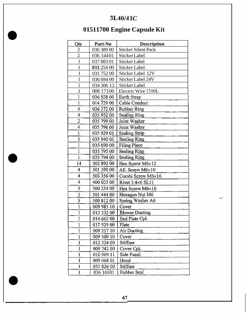
3L40/4 1 C
Qty 2 2 1 1 1 1
01511700 Engine Capsule Kit
Part-No Description '
036 389 00 036 144 01 Sticker Label 037 883 01 Sticker Label 033 254 00 Sticker Label 031 752 00 036 694 00
Sticker Silent Pack
Sticker Label 12V Sticker Label 24V
1 1
034 306 12 Sticker Label 008 173 00 Electric Wire 1300L

4L40/4 1
015 118 00 Engine Capsule Kit
Qty Part-No Description '
2 036 389 00 Sticker Silent Pack 2 I 036 144 01 I Sticker Label i 1 037 883 01 Sticker Label 1 033 254 00 Sticker Label 1 03 1 752 00 Sticker Label 12V 1 036 694 00 Sticker Label 24V 1 034 306 12 Sticker Label 1 008 173 00 Electric Wire 1300L
I 1 1 03692800 I EarthStraD 1 014 729 00 Cable Conduct 036 372 00 Rubber Ring
2 035 799 00 Joint Washer 4 035 798 00 Joint Washer 1 I 035 929 01 I Sealing Strip
~~
1 035 794 00 1 Sealing Ring . . 14 502 892 00 1 Hex Screw M6x12 4 50 1 390 00 All. Screw M6x 10 4 503 356 00 Combi Screw M6x16 4 400 025 00 Rivet 2 . 4 ~ 6 SL51 5 500 254 00 Hex Screw M6x10
I I -
3 I 501 444 00 I HexagonNut M6 1
1 009 069 01 Hood 1 036 162 01 Rubber Seal
1 1I 035 827 00 I Stiffner
68

8) IREBUILT KIT LOWER END
a MODEL REBUILTKITLOWER END
2LIM40 994 005 30
PAGE
70
3L/M40
4LM40
2LM4 1
994 005 31 70
994 005 32 71
994 005 43 71
69
3LM4 1
4LM4 1
994 005 44 72
994 005 45 72

2L/M40
. Qty Part-No Description 1 009 529 00 Air Filter LA4
994 005 30 Rebuilt Kit Lower End
2 1
009 734 01 012 309 02
Cyl. with Piston LM40 Gasket Set Crankcase L/M40/41
3 I 2 I 034633 00 I Thrust Washer ~ - 1
035 555 00 Main Bearing, Std. 1 035 687 00
I 2 I 036 18401 1 RodBearinrz I Rubber Diaphragm
I 1 1 036 489 00 I Breather Hose 1
Qty Part-No 1 009 529 00
3L/M40
Description Air Filter L M
994 005 31 Rebuilt Kit Lower End
I 1 1 400 213 00 1 1 400 653 00
Oil Pressure Switch Oil filter
I 3 I 009 734 01 I Cvl. With Piston LM40 I I 1 I 012 309 02 I Gasket Set Crankcase LM40/41 I
3 I 037 530 00 I Connect Rod Bushing
I ~ 1 ~ I 502515 00 I Fuel Filter Element I 1 1 I 503 170 00 I Fuel Pre Filter 1
70

4L/M40
Qty I Part-No 2 1 009 529 00
994 005 32 Rebuilt Kit Lower End ~
Description Air Filter L/M
4 1 009 734 01 1 I 012 309 02
~~
Cyl. with Piston LM40 Gasket Set Crankcase L/M40/41
2 5 1
~~
4 1 036 184 01 1 Rod Bearing
034 633 00 Thrust Washer 035 555 00 Main Bearing, Std. - 035 687 00 Rubber Diaphragm
1 4 1
I 1 I 400 653 00 1 Oil Filter 7
036 489 00 Breather Hose 037 530 00 502 722 00
Connect Rod Bushing Oil Pressure Switch
1 1
2LM41
502 5 15 00 Fuel Filter Element 503 170 00 Fuel Pre Filter
994 005 43 Rebuilt Kit Lower End
Qty 1 Part-No 1 I 009 529 00
Description Air Filter L/M
I 2 I 015 447 00 I Cvl. with Piston LM41 1
1 1 1
I 1 I 03648900 I BreatherHose 1
400 213 00 Oil Pressure Switch 400 653 00 Oil Filter 502 515 00 Fuel Filter Element
I 2 1 03753000 I ConnectRodBushina 1
I 1 I 503 170 00 I Fuel Pre Filter 1
71

3LM41
Qty 2 4 1 2 5
994 005 44 Rebuilt Kit Lower End
Part-No Description 009 529 00 Air Filter L/M 0 1 5 447 00 Cyl. with Piston L/M4 1 012 309 02 Gasket Set Crankcase wM40/41 034 633 00 Thrust Washer 035 555 00 Main Bearing.. Std.
4L/M41
1 4
994 005 45 Rebuilt Kit Lower End
036 489 00 Breather Hose 037 530 00 Connect Rod Bushine
1 1 1
I 1 I 035 687 00 I Rubber DiaDhrarrrn ~ - - I
400 653 00 Oil Filter 502 5 15 00 503 170 00
Fuel Filter Element Fuel Pre Filter
L 4 I03618401 I RodBearing
I 1 I 50272200 I OilPressure Switch I I I
72

0 9) REBUILT KIT TOP END
1 MODEL I REBUILTKIT TOP END
IZL/M40/41 1 994 005 29
I PAGE 1 I
74 1
7 One kit required per cylinder. 0
73

L/M40/4 1
994 005 29 REBUILT KIT TOP END One required per cylinder
Qty Part-No Description 1 009 922 02 Gasket Set Cyl. Head L/M40/41 2 I 030 434 02 Valve Retainer
I 2 I 031 490 00 I LackNut 1 2 031 835 00 Valve Spring, Inner 2 03 1 841 00 Rocker Bushing 2 031 851 00 Pressure Spring 2 031 852 00 Pressure Ring 4 032 332 00 Shim 0.2 4 032 333 00 Shim 0.3 2 033 256 00 Valve Spring, Outer 4 034 560 00 Shim 0.4 4 035 806 00 Shim 0.15 2 I 036 209 00 I Keeper (2=1) 1
74

10) CAPSULE FOAM KIT
I I 1 MODEL 1 REBUILTKITLOWER END 1 PAGE 1 2L40/4 1 C 994 005 33 76
3L40/4 1 C 994 005 34 76
4L40/4 1 C 994 005 35 77
Foam Kits do not include sealing strips and washers. ? For a complete foam and rubber overhaul, the corresponding rubber parts sets should be 0 ordered in addition to the foam kit.
75

2L40/4 1 C
994 005 33 Capsule Foam Kit
1 I 037 61 401 1 Rubber Insert, Oil
3L40/4 1 C
994 005 34 Capsule Foam Kit
1 Qty I Part-No 1 Description 1 ~
1 035 602 00 Sealing Strip, 93mm 1 035 637 01 Sealing Strip, 215mm
1 035 879 01 Sealing Plate 1 035 929 01 Sealing Plate 1 036 474 00 Insulation Board 1 037 504 01 Insulating Plate 1 037 614 01 Rubber Insert, Oil 1 035 874 00 Insulation Board 1 035 877 00 Insulation Board 1 035 934 00 Sealing Strip 1 036 161 01 Rubber Seal , 1 I 037 698 00 I Sealing Strip
76

4L40/4 1 C
Qtsr 1 1
994 005 35 Capsule Foam Kit
Part-No Description Sealing Strip, 93mm Sealing: Strin 215mm
035 602 00 035 637 01
1 1
I 1 I 035 651 00 I Sealing: S t r i ~ I 035 798 00 Rubber Washer 035 850 02 Sealing Plate
1 1
035 879 01 Sealing Plat 035 929 01 Sealing Plat
1 2 1 1 1 1
I 1 I 037 687 00 I Sealing Plate I
036 474 00 Insulation Board 036 476 00 Sealing Strip 03 7 6 14 0 1 012 055 00 Lining 035 935 00 Sealing Strip 036 162 01 Rubber Seal
Rubber Insert, Oil
1 037 690 00 Insulation Board 1 037 767 00 Insulation Board
t 77
1 1 037 768 00 Insulation Board

MAINTENANCE
L-M SERIES
LUBRICATION
Use API CD - CE - CF4 Oil
Viscosity according to temperature straight weight r .
multiviscosity 15W40 1QW30
summer winter
FUELS
ASTM D 975 DFlDF2
Extreme cold weather - dilute with kerosene
.
8/95

MAINTENANCE
L-M SERIES
General Information
At 25 hours - NewRebuilt
change engine oil and filter
check and adjust valves
check hardware for tightness
DO NOT RETORQUE CYLINDER HEAD BOLTS
8/95 0

* * suction tube way of pressurized oil baween pump and'fiiter (at engines without oil-coolW) way of pressurized oil between pump and filter i f engine is equipped with oil-cooler
r way of pressurized oil after oil filter
Rockers Pushrods Pushrod tubes Excessive fuel device resp. HATZ auto-protection device Cranks haft Main bearings Hydraulic belt tensioner lub.-oil pump Oil sump
10
11
12 13 14 15 16 17
Closing plugs (engines without oil cooler) Closing screw (engines with oil cooler) Oil suction sieve Counter rotating balance shaft(s) Lub.-oil filtec with bypass valve Oil cooler \ Oil pressureswitch Oil relieve valve

Oil Viscosity
Ed. 08,97 MSS-schi-es
Choose an engine oil viscosity that matches the ambient temperature
I when the engine is cold.

0
0
I
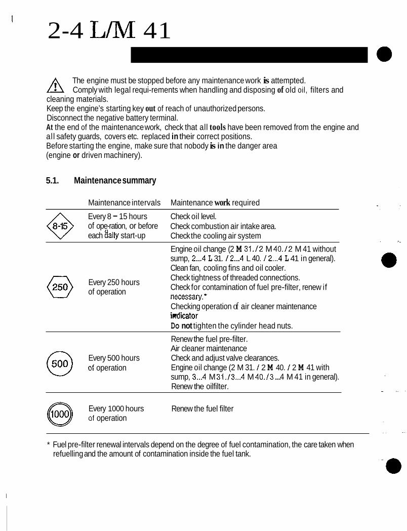
2-4 L M 41
The engine must be stopped before any maintenance work is attempted. A Comply with legal requi-rements when handling and disposing of old oil, filters and cleaning materials. Keep the engine’s starting key out of reach of unauthorized persons. Disconnect the negative battery terminal. At the end of the maintenance work, check that all tools have been removed from the engine and all safety guards, covers etc. replaced in their correct positions. Before starting the engine, make sure that nobody is in the danger area (engine or driven machinery).
5.1. Maintenance summary
Maintenance intervals Maintenance work required
Every 8 - 15 hours of ope-ration, or before each 8aily start-up
Check oil level. Check combustion air intake area. Check the cooling air system Engine oil change (2 M 31./2 M 40./2 M 41 without sump, 2...4 L 31. / 2...4 L 40. / 2...4 L 41 in general). Clean fan, cooling fins and oil cooler. Check tightness of threaded connections. Check for contamination of fuel pre-filter, renew if necessary.*
Every 250 hours of operation
Checking operation of air cleaner maintenance iRdicator Do not tighten the cylinder head nuts. Renew the fuel pre-filter. Air cleaner maintenance Check and adjust valve clearances. Engine oil change (2 M 31. / 2 M 40. / 2 M 41 with sump, 3...4 M 31 ./3...4 M 40./3 ... 4 M 41 in general). Renew the oilfilter.
Every 500 hours @ of operation
Every 1000 hours Renew the fuel filter @ of operation
* Fuel pre-filter renewal intervals depend on the degree of fuel contamination, the care taken when refuelling and the amount of contamination inside the fuel tank.

L/M VALVE ADJUSTMENT
Type
lmportan t: * urn the engine over in the normal direction of
Valve No. . Check valves fully open at cyi. No.
- rotation. This is counter-clockwise in either case - at the flywheel or timing gear end.
Important: Repeat the procedure for all valves, noting the adjusting method described above.
Adjusting method for two-cylinder engines - The valves in cylinder 1 (at the fan end) must
be in the overlap position (exhaust valve not yet closed, inlet valve just starting to open).
- Turn the crankshaft through 180 degrees in the normal direction of rotation, and check valve clearances at cylinder 2.
- Turn the crankshaft a further 180 degrees in the same direction as before, and check the valve clearances at cylinder 1.
Adjusting method for three- and four-cylinder engines (Figure 28)
1 3-cylinder 5 2 I 1 1 1 4-cylinder
I 3 1 I - Check valve clearances with a feeler gauge. -Valve clearances (inlet and exhaust valves)
= 0.10 mrn with engine cold. - If valve clearance is incorrect, slacken off hex
nut -1’. Turn adjusting screw ‘2’ until feeler gauge ‘3’ can just be pulled through between the rocker and the valve stem, with slight re- sistance to its movement, after nut “1‘ has been retightened (Figure 29).
.. f ’’
I W 4 6

0 SALES 0 ENGINEERING m SERVICE 0 PARTS
information Bulletin NO. SE36
Oate 09/30/96 -
Snbfectt J&M Engines Belt Replacem e&
This bulletin is designed to address the occasional belt life complaint on L and M Hatz engines. The belt generally lasts 2000 to 4000 operating hours, or two to three years, depending on operating conditions (i.e.: heat, dust, and other contaminants). If belt problems exist, please ask the customer to reference the L and M Instruction Book or send your customer th is information by fax or mail.
Major reasons for premature belt failure or repeated belt failure are:
Foreign material entering the blower fan. Binder twine and plastic, if they enter the blower fan, can strangulate the blower belt and pull it off the sheaves. This is not a common failure.
The major reason for repeated failure is incorrect installation and failure to inspect why they failed.
Inspection and Installation:
1) Remove covers to access belt. Look for foreign materials which may have caused failure.
2) Remove .lower pulley. Clean area below pulley.
3) Inspection
i r.. .-.
a) Does the alternator shaft turn h l y ? b) Are the blower/alternator pulley grooves in good condition? (i-e.: no knicks, no
c) Check sheaves and bearings of the hydraulic belt tensioner pulley. d) Check grooves for knicks and embedded material of the lower pulley.
material embedded)
Page 1 of3
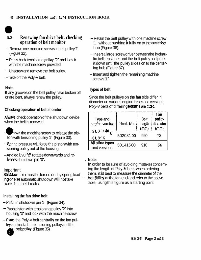
4) INSTALLATION ref: L/M INSTRUCTION BOOK
6.2. Renewing fan drive belt, checking operation of belt monitor
- Remove one machine screw at belt pulley '1' (Figure 32).
- Press back tensioning pulfey '12' and lock it with the machine screw provided.
- Unscrew and remove the belt pulley. -Take off the Poly-V belt.
8
Note: If any grooves on the belt pulley have broken off or are bent, always renew the pulley.
Checking operation of belt monitor
hvays check operation of the shutdown device when the belt is renewed.
m o v e the machine screw to release the pis-
-Spring pressure will force the piston with ten-
-Angled lever '2' rotates downwards and re-
ton with tensioning pulley '1' (Figure 33).
sioning pulley out of the housing.
leases shutdown pin T.
Important Shtrtdown pin must be forced out by spring load- ing or else automatic shutdown will not take place if the belt breaks.
installing the fan drive belt -?ush in shutdown pin '1' (Figure 34). - Push piston with tensioning pulley 2' into
housing 3' and lock with the machine screw. -Place the Poly-V belt centrally on the fan pul-
ley and install the tensioning pulley and the
- Retain the belt pulley with one machine screw '1' without pushing it fully on to the centthg hub (Figure 36).
- Insert a large screwdriver between the hydrau- lic belt tensioner and the belt pulley and press it down until the pulley slides on to the center- ing hub (Figure 37).
screws '1 '. - Insert and tighten the remaining machine
Types of belt
Since the belt pulleys on the fan side differ in diameter on various engine types and versions, Poly-V belts of differing lengths are frtted.
Type and
72 2L31 '40 3L31 c 502031 00 920
*Ii Other types 501 415 00 910 64 and versions
Note: In order to be sure of avoiding mistakes concern- ing the length of Poly-V belts when ordering them, it is best to measure the diameter of the belt ofilfey at the fan end and refer to the above table, using this figure as a starting point.
(y belt pulley (Figure 35).
SE 36 Page 2 of 3

32 33
36 c.%nikeke36.sam
37 SE 36 Page 3 of 3

HAT2 DlESEL OF AMERICA, I".
9 40. Hydr. beIt tensioner, disassembly and assembly
Preliminary work: L30, L3 I , L40 C/K - Remove cover from cooling air duct (6/20). L..S/Z,M 3 1, M40 - Remove belt guard if fitted. - Remove belt - (See attached instructions) - Remove allen screw (109/3) spring washers and adapter plate (109/4).
- Unscrew oil pipe (1 09/1) and remove allen screws (I 09/2)
- Lift out belt tensioner (10916).
- e r n b l e In Reverse Order ( S e e Tips Fig 110 & 111
must be in both sides of tensioner housing
Grease 0-Ring to hold in place against tensioner
ML I 1/96
8 ' I9

H a t z #009 529 00 A f t e r m a r k e t
( M f 9, unknown)
SEALING R I N G
170 FILTER PLEATS
NOTI3 SEALING RING COMPLETELY SEATED A R E A S OF POSSIBLE LEAKAGE CAUSED BY POORLY FITTING SEALING RING.
SEALING R I N G A N T A K E INTERFACE

L&M FILTER COMPARISON
Max operating psi Max flow rate (GPM)
Tesmurst psi Anti drain-back valve?
L&M series lubrication Characteristics:
203 psi 210 psi 14.3 GPM 9 GPM
232/? ?/500 ?/290 Yes Yes Yes
Flow 0 40 litre/min. @ 3000 RPM 0 23 litre/min. @ 1500 RPM 4 cyl. = 10.5 gal./&. = 6.0 gal./&.
20 litre/min @ 3000 RPM 0 11.5 litre/& @ 1500 RPM Flow 2 & 3 cyl. = 5.3 gal./min. = 3 gal./min..
Maximum oil temperature a 120" C (245" F) Operating oil pressure 3 .6 Bar to 3 Bar (8.7 to 44 psi)

WARTUNG .MAINTENANCE Xl"-l'ETIEN .MANTENIMIENTC
MANUTENZIONE
A n
STUNOEN .HOURS .HEURES HORAS .ORE
W A R N N G * MAINTENANCE ENlRETlEN . MANTENIMIENTO
MANUTENZONE
STUNOEN .HOURS. HEURES HORAS . ORE
J E N C A S O D E NECESIDAO
SE NECESSARIO

HATZ DIESEL OF AMERICA, INC.
Mounting Order Of Exhaust Gasket Sets
Auspuff Exhaust Echapp. Escape
Zyl.-Kopf Cy I.- head Culasse Culata
1 . . Cyl.-head I I CuIasse
P.O. BOX 2581 W229 N1645 WESTWOOD OR. 1 WAUKESHA, WI'53187-02581 PH: (414) 544-0254 FAX: 414-544-6120

FOREIGN MATERIAL IN ENGINE LUBRICATION OILS AND THEIR ORIGIN
Fe
Cr
Sn (tin)
A1
Ni
c u
Pb
Mo
Ca
Ba
P
Zn (zinc)
Na
Si
H C
Origin All gray casting and steel parts.
Piston rings, valves, gudgeon pin (top layer), component alloy of crankshaft and camshaft (with Cu).
Bearing shells (top layer) and component of bronze.
Piston, cylinder head and crankcase (light alloy).
Valves, valve guides, steel, etc.
Bearing bushings (second layer) etc.; one element of brass and bronze.
Component of secondary layer of bearings.
Piston rings and oil additive.
Additive of lubrication oil and anti-freeze fluid.
Additive of lubrication oil and anti-freeie fluid.
Light alloy parts and oil additive.
Oil additives and mineral dust.
Oil additive.
Oil additive.
Oil additive and one component of brass (with Cu).
Oil additive and anti-freeze fluid.
Light alloy (with A1 + Mg), mineral dust, oil additive, seal rings, etc. to verify: check for relationship with A1 + Mg.
Fuel Enters the oil due to improperly functioning injector nozzles or porosity of pump housing. Fuel in the oil mainly counts if the engine is operated under light load and speed only which keeps the lubrication oil temperature at a very low level thus fuel does not vaporize and remains in the oil.

Element Origin Negative influences of fuel in the oil.
Oil viscosity getting too low with the risk of improper lubrication mainly with bearings and camshaft to cam followers.
Lubricating oil level getting too high (over maximum mark of dipstick) which causes the crankshaft and conrods to dip into the oil and came a lot of internal fi-iction with high temperature of the engine and of the lubricating oil.
Water Is a product of combustion of fuel but in vapor form. Through the blow-by a certain percentage of the exhaust gas enters the lubrication oil. In all cases where the oil temperature is extremely low the water will not vaporize, then it undergoes a chemical reaction with sulfur oxide and may lead to corrosion on internal engine components. Engine oils usually contain bases to neutralize such acids.
Glycol The main component of coolant fluid (anti-freeze additive.) If Glycol enters the oil and the oil reaches extremely high temperatures (about 150°C) it leads to heavy oxidation and thickening of the oil. In extreme cases the oil becomes solid like bitumen and can no longer be pumped to the bearings. Though Hatz engines are air cooled and do not require coolant fluid, we already experienced Glycol entering the lubrication oil just by using an oil drum or canister which was used to refill Glycol into water-cooled engines (2 percent or 20 cm3 per liter is sufficient to cause the afio described problem).
Oxidation and viscosity
Oil is a hydrocarbon and undergoes oxidation if it gets in contact with oxygen. Oxidation causes thickening of oil to an extent which may block the whole oil circuit. The oxidation can be measured, but is also indicated by increased viscosity which is also measured and indicated in “centi-stokes” and the corresponding SAE class.

Cr Sn Al Ni c u Pb Mo K B Mg Ca Ba P Zn Na Si
Element Abbreviations
Iron Chromium Tin Aluminum Nickel Copper Lead Molybdenum Potassium Boron Magnesium Calcium Barium Phosphorus zinc Sodium Silicon

BASIC TRICAL
-
WIRING DIAGRAMS

H.D.A. WIRE COLOR CODING - AS OF 10199
WIRENO. COLOR: APPLICATION: 0 1 2 3
4 5 6 7
9 10
11
12 13 14 15 16 17
18 19 20 21 22 23 24 25 26 27 28 29
8
green red white yellow (see note A) blue/white blue/black brown orange brown (see note B)
blue/red
orangeblack (see note C)
blue (see note D) bludyellow (see note C) yellowMack blacWwhite blueJwhite (see note B) blue (see note B) redwhite red/blue (see note B) black blac Wred blue (see note C)
violet (see note C)
NOTES -Wire Color Coding A = Before new power box system B = Wire color subject to change C = Used after Sept 99’ D = Used before Oct 99’
Ground B+ D+ Starter solenoid - terminal 50 Stop solenoid - “pull” coil Oil pressure switch Cylinder head temperature switch Glow plug Stop solenoid - “hold” coil Glow plug - 4 cylinder Auto-start input (Special application) Precision speed adjustment - motor positive (Special application) Precision speed adjustment - motor negative (Special application) Oil pressure gauge Reserved for special applications Two-speed - “hold” coil Reserved €or special applications Decompression solenoid (Special Application) Air restricter switch Air restricter switch Stop solenoid - “pull” coil Cylinder head temperature gauge Oil temperature switch Belt break switch Tachometer signal Ammeter Alternator Ducati C Oil temperature gauge Anti-restart module - AUS terminal Reserved for special applications Speed adjustment solenoid - “pull” coil Reserved for special applications

HATZ-specific markings Terminal designations in the HAT2 instrument box
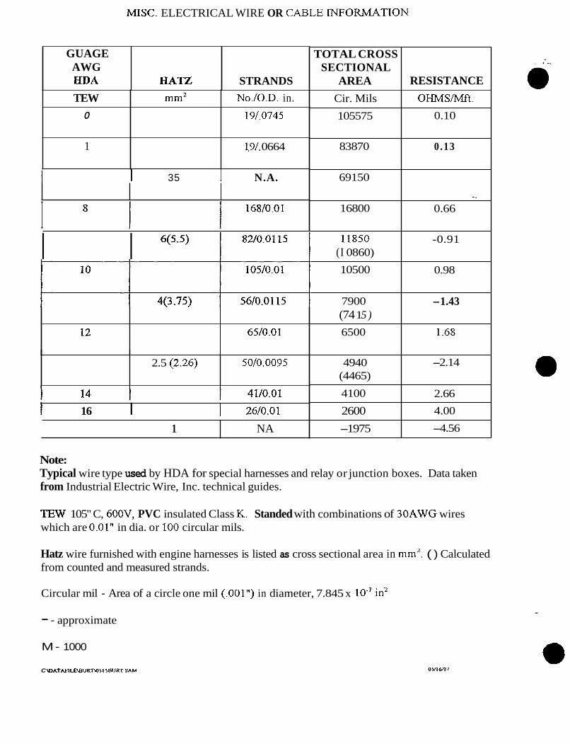
M I X . ELECTRICAL WIRE OR CABLE i"FORMATI0N
TOTAL CROSS SECTIONAL
AREA Cir. Mils 105575
83870
69150
16800
I1850 (I 0860)
10500
7900 (74 1 5 ) 6500
4940 (4465)
4100
2600 -1975
RESISTANCE oHMs/Mft. ~
0.10
0.13
-_ -
0.66
~
-0.91
0.98
-1.43
1.68
-2.14
2.66 4.00
-4.56
GUAGE AWG €IDA
I 35 I N.A.
HATZ STRANDS
I 8 l I 168/o.01
TEW 0
1
6(5.5) I I
mm2 No./O.D. in. 19/.0745
1.9/. 0664
2.5 (2.26)
I 16 I I 26/0.01
50/0.0095
1 NA
Note: Typical wire type used by HDA for special harnesses and relay or junction boxes. Data taken from Industrial Electric Wire, Inc. technical guides.
TEW 105" C, 600V, PVC insulated Class K. Standed with combinations of 30AWG wires which are 0.01" in dia. or 100 circular mils.
Hatz wire furnished with engine harnesses is listed as cross sectional area in mm'. ( ) Calculated from counted and measured strands.
Circular mil - Area of a circle one mil (.001") in diameter, 7.845 x in2
- - approximate
M- 1000
C \DATMLRBURT\OII IHURT S A M

HATZ DIESEL OF AMERICA, INC. W229 N1645 Westwood Drive
WIRE SIZE CONVERSION TABLE Wiring diagrams for the Hatz engines show a wire identification which is a European standard. These standards have a cross reference to American wire sizes as follows:
HATZ SYMBOL
.752
l2
1 .52
2.52
42
62
1 62
252
AMERICAN WIRE GAUGE NO.
18
16
14-16
12-14
10-12
10
4-6
2-4
In many cases, past experience of the application will allow the customer to select between the two sizes as noted above. To be on the safe side, the larger wire size should be used when making modifications to the wiring because most likely the new wire length will be longer than the original.

~
Motorenfabrik HATZ. Dept. 1 A I Mr. Buchinger, Mr. Lohmuller Date: 01.03.95
Markings in HATZ circuit diagrams (as per DIN 40779)
New mark- ing
A l A 2 A 3 A 4
B 1 B 2 B 3 B 4
C l
E l
F 1
G I G 2 G 3
H 1 H 2 H 3 H 4 H 5 H 6 H 7 H 8
K 1 K 2 K 3 K 4 K 5 K 6 K 7 K 8
(DIN)
Designation of electricaI components
Instrument box Instrument panel Automatic start-stop Starter protection module
Temperature sensor Pulse speed sensor Oil pressure sensor Acoustic signal
Capacitor
Heater for fuel filter
Fuse
Battery 3-phase generator Flywheel alternator
Indicator, charging indicator lamp Indicator, oil pressure Indicator, engine temperature Indicator, air filter (maintenance switch) Indicator, belt monitor Indicator, glow indicator Indicator, fan monitor Remote indicator lamp: engine on
Control relay 1 start / antirepeat start Controi relay 2 pre-glowing Control relay 3 ‘speed adjustment Engine protection relay Time-lag relay Start interlock relay Timing relay (pulse relay) Leistungsrelais
-
Former mark- @ ing (HATZ)
- 202 201
171
167 193
-
197
179
125 126 126 0 129 129 129 129 129 123 129
151a 151b 151c 177 160 153 198

Motorenfabrik HATZ, Dept. TA / Mr. Buchinger, Mr. Lohmuller Date: 01.03. 95
N 1 N 2 N 3 N 4
P 1 P 2 P 3
R 1 R 2 R 3 R 4 R 5
s1 s2
s5 S 6 s7 S 8 s9 s 10 s 11 s 12
T 1
v 1 v 2 v 3
w1 w2
a
Starter motor Starter alternator
Regulator for starter alternator Reguiator for flywheel alternaror Regulator for 3 -phase generator (unless integrated) pulse generator (supplementary to Syncro regulator)
Hours meter Rev counter Pressure indicator
Glow plug Heater flange Series resistor for preheater Resistor Series resistor with thermostatic switch
Glow starting switch Ignition light switch Preheater starter switch
Switch for speed adjustment Temperature switch €or engine temperature Oil pressure switch Pressure switch for air filter Fan monitoring switch Temperature switch for preheating Remote start switch Remote stop switch
Start-Stop switch
Transformer for rev counter
Decoupling diode Free-wheeling diode Zener diode
Ground, negative return line Shielded line on alternator
127 120
124 124 124 - 169 203 168
121 130 163 181 -- 182 128 122 191 190 161 167 170 176 - - - - 159 159 195 - -

Motorenfabrik HATZ, Dept. TA I Mr. Buchinger, Mr. Lohmtiller Date: 01.03.95
x1 x2 x3 x4 xs X 6
Y 1 Y 2 Y 3 Y 4 Y 5
21 2 2
Terminal strip on instrument box Flat quick-connect distribution box Connector on Emergency Stop switch Socket on Emergency Stop switch Terminal block in operators panel Terminal block in terminal box
Solenoid for speed adjustment Solenoid for engine shut-off Servo-magnet (= solenoid valve) for engine shut-off Fuel shut-off valve High-pressure shut-off valve
Interference suppression filter Interference suppression capacitor
- 173 156 155 - - 172 157 194 158 18 1
199 200

Siartrtnrichtunq Start inq aevtrc Oisous ac acraarr 1 Stroarrrsnrgung I I aoccinrithtung
P a w S U D D I V I Charging device Altrrntllion t lrctr / Chrrpcur
siaiilrnt l t i tungen onnt Ouerschnittsangabc sin0 1' AI I m s wiihout tonouctur cross section d b t i drt 1 ' rou t ler cdalts m s indication de section sont dr 1'
u *. -I- .-- ....- ifberrachunq I Antcige Monitoring I diSDlay Sur.tci I lancr t tcaoin - I - . u < - c ....-
Hubragnet tur HotordbslclIunq miuqsslroh 4 4 3 A , Hallestroa 0.t A
Solrnotd lor engine slop irirush Lurrenl 44.5 A . holding current o,b 1 El:aimant d drrct OII mot ' courant d action 44.5 A . caurdnt or main1 0 . b A
1 ..VU -...- -.-.---_I---.. *..-...*--I-
HlWCiS: Jtoc inochny der vcrdrdntunq erforaert cine Gicksrvxne ail ammk ! r Instruct hi cnanqa in h e wiring rcqvire a consul~ation ol lhr ldclorr I 2 G 30 / 2 G 40:

(-3) Jowuapuox w 6un3IoISn3z~~ej
neo '00 9L1 510
6ue1 001. '6un~13t6naz~uej VKiO '00 106 010
\. /
J~U~PW~H we 6un31316nazJ~Uej (-) two '00 ELI EIO
6uot 001 '6unTlo16.nmuej WO '00 9f6 010
6UQ[ '6unqlo[6naz~uoj (7) rZ80 '00 168 010

Me* Codt l o r HA12 C i r c u i t Otagr. (acc. t o german stand. sgtc . OIM407191
@ode ~SIGNATIOH OF ELECTR. COUP.
A1 Instrument box AZ fnstrument panel A 3 AUtOm8t lC S t a r t stoo device A4 Stwter oro tec t ion module 81 l e w e c a t u r e sensor 82 Rev. DUlSe counter 03 O i l o r e s su rc sensor 04 Horn
E l He8teP device f o r f u t l f i l t e r F1 f u s e 61 Bat t e ry 62 3-phase gcnerr tor 63 Flyuheel a l t e r n a t o r H l Ind ica to r 1aro f o r b a t t . /generetor w Indicrtor larg fo r oil gressure H3 Ind ica to r lrrp l o r engine terg. I44 Indic. l a w for air f i l t e r (mainten.) it5 I n d i c r t o r lamp fo r V-belt f a i l u r e
H7 Ind ica to r Iaro for blower HI3 Remote ind ica to r leap: engine on K t Control cclry 1 for s t a r t / a n t i - r e s t a r t K2 Control r e l a y 2 for ore-glowtng
a4 Engine w o t c c t i a n r e l a y ~5 T i m e r e l a y (delay) K6 Star t- locking r e l ay
K8 Power rtflay MI S t a r t e r motor nG S t a r t e r genera tor N1 Aegulatur f o r s t a r t e r genera tor NZ Regulator for f lyuheel a l t e r n a t o r ~3 Regulator f o r 3-phase genera tor Nd Impulse t r ansmi t t e r I f . Syncro-regul. 1 Pi Hows-run reter P2 Rcvoluttons counter P3 Pressure i nd ica to r R1 Glow plug R2 Heater f lange A 3 Series resistor for glowing device R4 Reslrtor RS Series rasistor w i t h thermostat. w i t c h Si 610w s t a r t i n g switch (5 pos.1 SZ Main twitch S3 S4 St~t-StOo-SWitCh s5 WjtCh f W Speed 8djUStclent s6 1e.pcrr tue s n i t c h for engine teap. s7 O i l p r e s s u r t switch 30 Press. w i t c h f o r air f i l t e r ( 8 a i n t t n . l S9 Switch far blower con t ro l SlO lcwtrrture switch for oreheating
TI Trsnrlormer l o r speed mesurcment VI Oecouallng diode v2 Suppressor diode v3 Zener diode v4 Surge rupressor Qladc HI Ear th / ground. minus return wi? Screened cable r t genera tor xi lermlnrl s t r i p a t instrument box x2 l a b connector block x3 Plug a t emergency $tog switch x4 Socket a t s t a r t s t o p swi tch x5 Terminal block i n ope ra to r s panel X 6 Terminal block i n terminal box ri Solenole for speed rdjustmcnt y2 Solenoid f o r engine s t o p y3 Solenoid-valve l o r englnc stop ~4 m i w t - o r r W I V ~ rs High-pressure shut o I f va lve 21 tntcrtcrmce suaorersbon c o i l 22 Suopresslon caoacr tor
c1 C l O l C ~ t O f '
H6 Glow plug ind ica to r
KJ COntPOl cel8y 3 for speed 8djUStUtnt ,
K7 IBDUlSe r e l ay
610w S t a r t i 0 9 switch (3 QOS.1
Sli RLMte S t a r t switch 312 ReWte St00 Sn i t ch

1 I I I I
t 1
L

Instrument Control Boxes
Standard Control Box Engine Accessory Part Number
01112202
B I
. r
Standard Control Box
Indicator L i g h t Options 1 w i t h Preheat and Temperature
Auto Stop Control Box Spare Parts Number
01112802 . Engine Accessory Part Number
01112302 Preheat Kguipment is Optional

-0 Wire Terminals in the Standard Control Box
24 - charge wire 18 - shutdown solenoid - cLpullyy voltage (if so equipped) 1 - shutdown solenoid - ccholdyy voltage (if so equipped) 6 - pre-heat 5 -temperature switch 4 - oil pressure switch 3 - starter motor solenoid 2 - charge light and anti-restart 1 - positive wire (plus) 0 - ground wire (negative)
Extra Wires
1 14 - two-speed solenoid - LCholdyy voltage I
22 -tachometer / hourmeter 28 - two-speed solenoid - LLpullyy voltage
I

HAT2 INSTRUMENT BOXES
a
-. DESCRIPTION I 'ART NUMBER ENGINE SERIES
10776900 €75 €79
1D31/41Z & ID81 C,Z 11 402901 STANDARD
1D31/41Z & I D8lC,Z 11406901 UJTO SHUT DOWN
I1 524900 STANDARD 2G40
I1 526700 UJTO SHUT DOWN 2G40
I1 112202 STANDARD 2790
11 1 12302 AUTO SHUT DOWN 2790
2/3/4/M40/41 & 2/3/4/L40/41 C 1081 7702 STANDARD 12 VOLT
2/3/4/M40/41 & 2/3/4/L40/41 C 30826502 STANDARD 24 VOLT
2/3/4/M40/4 1 & 2/3/4/L40/41 C WTO SHUT DOWN 12V. 00824603
2/3/4/M40/41 & 2/3/4/L40/4 I C 0081 9603 AUTO SHUT DOWN 24V.
ALL 99400253 RELAY CONTROL PANEL

- HkTZ O I E S E L K E Y S M I T C H
~
..*-
o l d style key s w i t c h P.N. SO276500 incl. k e y 0 new style key s w i t c h
P o N o 50276501
k e y P.N. SO166400 key P.N. 50166410
FRONT VIEW REAR VIEW
U
15 8 30
17
6 PR O N G CONNECTOR 4 PRONG PLUG COGHECTEIR PLUG P , N o SO276700 P o N o 50276600

.. i 6 30 P -ACCESSORY 0 -OFF I -RUN I I - PREHEAT 1 SPRING RETURN TO I 111 - START RESET START BY TURNING TO OFF
MAXIMUM ELECTRICAL LOAD OF TERMINALS:
TERMlNAl MAXIMUM LOAD AT - LOAD 24v PERIOD
m POSITION flUMBEq l2.X -
P 58 8A 4A . UNLIMITED
I 15/54 8 35A 17.5A UNLIMITED
I I 15/54 35A 17.5A UNLIMITED 19 60A 30A 2 MINUTES
111 15/54 35A 17.5A UNLIMITED
FRONT VIEW
17 50a
60A 60A
60A I MINUTE 40A SHORT TIME 50276502
REAR VIEW -
KEY SWITCH
wiringlm.pre 12/95 jk

7
HATZ DIESEL KEY SWITCH USED ON ALL ENGINEX WITH ELECTRIC INSTRUMENT BOX i
The key switch used by HATZ is an automotive type Switch which has five key positions. The key can be inserted or removed in either position F or 0. In the other three positions (I, 11, 111) the key cannot be removed . Also, position I1 and I11 are spring-loaded and upoK releasing the key it will re tu rn to position I.
The front mounting surface of the switch has two raised square pegs for proper installation. These pegs properly align the switch and.also hold the switch in place when the mounting nut is tightened. It is also possible to install the switch upside down. NOTE: Mounting the switch upside down should be avoided.
The rear of the switch has ten plug-in type terminals. Two are for battery connections and the other eight are output terminals.
The new key switch 50276501 has an improved internal mechanism, which has no tendency to get stuck in the wrong position. The new switch alsc has a new key. NOTE: The keys of the two switches are not inter- .changeable- The installation of the switch, measurement or size and electrical load of the teminals are identical to the old switch.
KEY SWITCH POSITIONS: P - ACCESSORIES 0 - OFF I - ON OR RUN I1 - PREHEAT - SPRING REZURN TO POSITION I III - START AND PREHEAT - SPRING RETURN TO P O S I T I O N I
TERMINAL NUMBERS AND USE: 15/54 - GENERAL OUTPUT - 2 TERMINALS 30 - POSITIVE BATTERY INPUT - 2 TEXMINALS 19 - OUTPUT TO GLOW PLUG - 2 TERMINALS 17 - OUTPUT TO GLOW PLUG - 2 TERMINALS 5Oa - OUTPUT TO STARTER SOLENOID - 1 TERMINAL 58 - TERMINAL NOT USED - 1 TERMINAL frLAXIMUM ELECTRICAL LOAD OF TERMINALS: KEY TERMINAL MAXIMUM LOAD AT LOAD PERIOD
POSITION NUMBER 12 v 24 V
P - 5a 8A 4A UNLIMITED I 15/54 3 5A 17 . 5A UNLIMITED I1 15/54 3 5A 17 . 5A UNLIMITED
19 6 OA 3 OA 2 MINUTES I11 .15/54 3 5A 17.5A UNLIMITED
17 6 O A 6 0 A 1 MINUTE 5Oa 60A 4 OA SHORT TIME

I I I I I I I
. I I I 1 I I I I I I I I -
.. .
0
..
I I id I
I I I I I I 1 I I I I I I 1 I I I I

a 2.2 Pf
VI 1 I v1
I I
I s1 H1
I
I
CHARGING CIRCUIT j
B t D-
Y
REGULATOR >
)-I-
1
I I

CHARGING CIRCUIT
HATZ uses a Valeo 12 volt alternator in the L and M model engines. The alternator stator windings produce 3 phase alternating current, which is then rectified to DC. The voltage regulator is also a part of the alternator. Take care when removing the regulator from the alternator as the field brushes are a part of the regulator module.
The charge light and the number two wire are used for field excitation and indication of charging. A bad connection or bulb will cause a charging failure. The diode is used to block alternator voltage from returning through w i r e 2 to the switch, when it is switched off.
The enlarged diagram is of a Pharis Rhone alternator. For proper service information and repair procedure, consult the HAT2 Repair Manual.
.. . I

4MPERES
/
!
?500
10 4c ,O
MXll ~ O W N O . l 0 0 0 W U L M ? W U T r
/
3000
6c
2.11:l Pulley Ratios 1.9: 1 Engine Models 2-3L3 1 2-4M31
2L41c 2-4M40 2-4M41
2L40c 2L40S/Z
3L40C 3L41C 4L31/40C/41C I
4,-
-L_
u -..\ ENGINE R.P.M. - 1.9 : 1 ra'
3000 ENGINE R.P.M. - 2.11 : 1 t
80DO ALTERNATOR R.1
ALTERNATOR OUTPUT I DRAWN BY I APCROVEDBY: SCALE: -
L & M 40121001 DRAWNO NUMU
HAT2 DIESEL of AMERICA, INC. 99400

WIRE TERMINAL CONNECTIONS FOR 99400383 AND
40121001 ALTERNATORS
B+ Battery positive cable No. 1 D+ To indicator lamp cable No. 2 D- Ground connection cable No. 0 W Tachometer connection cable No. 22
NOTE : If the bulb circuit (cable 2) is not functioning correctly, or the bulb is burned out, the D+ circuit will not excite alternator. (Alternators will not charge if bulb is burned out.) Replacement bulb is P/N 40009700, the rating is 2 watt. Do not attempt to bypass bulb circuit.
BOX 258 W229 N1645 WESTWOOD OR. 1 WAUKESHA, WI 53187-0258 3 PH: (414) 544-0254 FAX: 414-544-6120

COMMON CAUSES OF ALTERNATOR FA.lLURE
Interchange positive and negative battery cables
0 Disconnect of battery with engine running
Short of positive cables to fiame
0 Burned out bulb
Welding on chassis without disconnecting (B+ D-)dternator
* Water, dust Contamination
Use of solenoid devices without use of clamping .. . diodes

4

Starter Circuit - *
The starter motor is a 12-volt solenoid operated positive engagement pinion gear type. The starter protection relay is used to keep an operator from engaging the starter while the engine is running. Since it was introduced around the end of 1986, starter failures have decreased.
0-
Major reasons for starter failure:
1). Keyswitch to start when the engine is running, causing starter pinion and ring gear damage. NOTE: Always inspect the ring gear teeth all the way around the gear before replacing a starter only.
2). Cranking the engine beyond the duty cycle, causing the starter motor windings to overheat and burn. NOTE: Duty Cycle: crank the engine a maximum of 15 to 20 seconds at one time, then allow 40 to 60 seconds for the starter motor to cool before cranking again.
3). Corrosion, dampness and rust in the starter; A). Do not high-pressure wash directly on the starter motor or starter
solenoid. B). If a ''sticky" starter is observed, the unit should go to the shop for
0 maintenance.
We tend to see more starter failures in colder weather. The chart below indicates cranking power vs. temperature.
i-
The amount of work the battery hacr to perform i n c r e a s e s a s t h e t e l l l p m ~ 1 6 I o d Duetofit€€€ oiI encountered atIooptempemtares, i t e s 2% times as muchtorque or crddngpowerto auP an engine over at 0" F as compared to 80" F, see Fig. 2.
'80' F 32' F 0' F FIG. 2 - R A W OF CRANNNG POWER
REQUIRED VS. TEMP. . .
The charge of t h e battery has an important bearing on the amount of work that the battery is capable of,

B A m R Y CAPACITY .(TEMPERATURESENSITIVE)
vs. POWER NEEDED TO START ENGINE
-1 a i? .... . . ....... ...... ..... . . . , . . .. ....... ..... ....... .... .......... ............... .........
~ 08.; - - .............. . . . .. ._._.-.. _. . ............ . . . . . . . . . . . . . .. . . . . .. ............ ................. ........... ......... ........ . . . . . .......... ......... . . . . . . . . .
I to I
I to 2.5
I to 6
k-3 ..... .... .... .....
I to 15

L
L ccs t
10 9
8
7
6
5
4
3
2
I
OC -10 .
Force of Cranking
Oil Viscosity vs.

Engine Model E 673 1 B20/30 E 75/79 1 D31/41 1 D81 2 G40 2 790 2L41COM41 3L41C/3M41 4L41CI4M41
Battery Size Recommendations - 12 Volt System Values Shown in CCA (cold crank amps)
Capacity of Maximum At At At 12VStarter Recommended
68F 3 2 F OF in kW Capacity of Battery 220 280 340 0.8 370 220 280 340 0.8 370 220 280 340 0.8 3 70 220 280 340 1.4 370 280 340 410 1.5 430 280 340 410 1.7 430 310 410 600 1.9 680 340 430 600 2.7 890 430 550 680 2.7 890 550 680 780 2.7 890
If approximate Amp. hour (Ah) ratings are required, divide cold cranking Amp. rating by 6. Example 890/6 = 148 Amp. hours.
The necessary capacity for a 24-volt battery is approximately 0.5 x capacity of the 12-volt
0 battery- When comecting batteries in series, the voltage is additive and CCA remains the same; connected in parallel voltage remains the same and CCA is additive.
Baffew Cables Recommended battery cable size is shown below.
Minimum Battery cable Size (Wire Gage) for 1 Meter Length
Wire %e
Single Cylinder Two Cylinder Three - Four cylinder
- 4 2 0
- -

COLD WEATHER STARTING CHARACTERJSTICS
> FUEL - DFl below 32" F
> OIL - Multi-Viscosity 15 W40 above 32" F 5W30 below 32" F
>BATTERY - 680min. CCA 890max. CCA
> BATTERY CABLE SIZE - 0 gauge
k GLOW PLUG - 2 - 3 minutes on while cranking
> THROTTLE - high speed position for start-up
> REMOVE PARASITIC LOAD?

Elektrostarter ISKRA 12 V und 24 V Spare Parts for Electric Starter ISKRA 12 V and 24 V
Prikes d6tach6es pour demarreur electrique ISKRA 42 V et 24 V
A

MOTOREN . L 4 1 C u n d . M 4 1
Pa.
0
ENGINES . L 4 1 C a n d . M 4 1 MOTEIJRS . L 4 1 C e t . M 4 1
Ersaizteilefiir Elektrosrarter ISKRA Spare Partsfor Nectric Starter IS= Pr2ces d6tWhkes pour d 6 m e u r 6lechique ISKRA
~
Benennung, description, dhignation
Starterkomplett 504 761 00 starter motor unit d6marreur cornplet
Ident-Nr., No. ident. l 2 V 24V
504 791 00
2
1 Frontgehtiwe I front end cover I carter avant
Magnetschalter 490 717 00
149071600 I
4
5
6
7
8
Lagerbuchse vorne 490 720 00 front end bush douille de palier, avant wicklung 490 721 00 coil bobme Biirstenhalter 490 723 00 brush holder
Kohlebihten 490 725 00 carbon brushes balais de clxxbon hintererDecke1 490 727 00
Wrte-balai
solenoid
fork mechanism mhnisme fourchu.
9 . couvercle d ? x e hinteres Lager 490 728 00
10
11
12
13
I rear end bearing I Dalier arrihre Anker 490 729 00 rotor rotor Ritzel wid Freilauf pinion gear engrenage A pignon Mitteldeckel 490 732 00 cover between couvercle central
fastening parts pi- de fixation
490 731 00
Befestigungsteile 490 733 00
90 716 00 -l 90 719 00
.90 720 00 -7 190 722 00
19072400 I $90 726 00
490 728 00 I
MF-Mei-rl 25.02.99

a- x!&!
+n

INDICATOR LIGHT CIRCUIT
THE CHARGE LIGHT
The charge light is controlled by the alternator. When the alternator starts to produce, the light w i l l extinguish.
~
~~ THE L O W OIL PRESSURE LIGHT
The oil light is controlled by the low o i l pressure switch (162) which is normally closed. When oil pressure reaches about 0.7 bar, the switch opens.
THE AIR RESTRICTION LIGHT
The air switch (170) is normally open and works by vacuum. A restricted air cleaner or obstructed air i n l e t will close the switch. 0 THE HIGH TEMPERATURE LIGHT (OPTIONAL)
The temperature light is controlled by a normally open switch (161). This switch will close at or near 220 degrees Celsius. __.I.
~~
Another optional warning light is the belt breakage light. Sfnce all the engines are automatically protected f r o m belt breakage, this light is not used.

Oldruckschalter-Bestuckung Application of oil pressure switches
Standard 2 G...
2-pol.
Motor Engine Moteur
1
502 938 10
503 452 01
0,3 ... 0,6
l,o 2 0,2 *
Version
2 / 3 / 4 M 3 1 - 4 0 - 4 1
2 /3 /4L30 -31 -40 -41
2 /3L30 -31 -40-41
Ident-No.
alle / all / tout
S - Z
C
bar (2025 oC)
4 L 40 - 41 I C (n ~ 2 3 0 0 ) 502 722 00 2, I
400 213 00 I , I 504 691 00 1 B20 1630
0.8 ... 1.2 1
1 I
1 D 30 ... 81 400 213 00 I altern. 502 722 00 I alle / all / tout
0,5 ... 0,8
400 213 00
400 213 00")
0,5 ... 0.8 ..
0,5 ... 0,8
.drift: 0.15 bar 40 "C ') Pos.: Kurbelgehause / crankcase 2, Pos.: olkiihler / oil cooler 3, alpumpe 1 Oil pump / pompe huile: 9.5 rnm
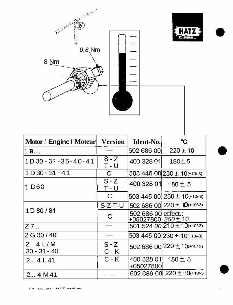
0,8 Nm
8 Nm \
Motor I Engine I Moteur Version 1 B...
1 D 30 - 31 - 4.1 I KJ 1 D30-31 -35-40-41
C
502 686 00 502 686 00
I
1 s - z
220 t I O(+10/-3)
effect.:
I D60
t05027800 501 524 00
1
250 f I 0 Z I O ?- I O(+1OW
I T - U
2G30140
C
---
I S-Z-T-U
502 686 00
1 D80/81
220 f I O(+?O/--3)
I c I --- z 7...
2... 4 L I M 30 - 31 - 40
s - z 1 C - K 2... 4 L 41 I C - K 2... 4 M 41 -
Ident-No.
400 328 011 180 2 5

HATZ RELAY (m?) P e N . 50277701 - RELAY 9 2 V P.N* SO277801 0 RELAY 24V P.N. SO276000 0 RELAY BASE P.N. 40074700 0 U I R E TERnINALS
07 - I
RELAY FRONT VIEW
RELAY B OTT CIPl V I E W
RELAY BASE fRONT VIEW
RELAY BASE TOP VIEW
RELAY BASE eaTTam VIEW
WIRING O I A G R A f l SYPlEOL

40074700 40098700 TERN I NAL TERN1 NAL
LOCK I FIG TAB
LUCK I NC TAB
C 0 N NE CT OR
I N S E R T REFlOVAL T O O L HERE
CUTAWAY SIDE VIEW
TERPIINAL AND CONNECTOR TOP VIEW
Open barrel terminals require special crimping pliers. After the terminal is crimped on the wire, check it. Give a little tug on the wire and terminal to m a k e sure the connection is tight. If a proper connection cannot be achieved, solder the joint. This will insure that you have a good connection.
REMOVAL OF LOCKING BLADE TYPE TERMINALS
A small screwdriver or piece of flattened wire can be used as a removal tool-
Insert removal t o o l into the slot in the top of the connector. Then turn the tool 180 degrees, this should push in the locking tab. This procedure may need to be repeated before removal is possible- If this procedure fails, turn the tool 90 degrees and pry against the terminal. This should force the locking tab in.
NOTE:. -It helps if you push up on the terminal while using the removal tool.

B
.. .
I I I
I I I
I 1
I I
I I
I I I
I
1 I 1
I
I I I
I I
I
I I I I I
I I I 1 I
I I I I I I I I 1 I
I t I I I t I I I I

GLOW PLUG CIRCUIT
The glow plugs utilized by HAT2 in multi-cylinder engines are actually intake manifold preheaters. The dropping resistor (123) is used to limit current flow and not necessarily as an indicator. Terminal 19 of switch 182 is a low current contact, terminal 17 can handle the higher current which is needed during the starting mode, Four- cylinder engines require a relay to energize the second glow plug, which again protects the switch from too much current draw.
., .

GLOW PLUG
E 71, 75, 7 9 and 780
F l A N l F O l D PREHEATER
DROPPING RESISTOR ASS€RBLY
T 4 //
lSTOR flE NT
VIEW
P SCREW

n
I - - - - - - -
/ $";"\ I
I
1- I - - - - -
-tr' " la;
1

STOP SOLENOID
The stop solenoid indirectly controls the fuel control rack. This solenoid has two windings, the number 3 wire powers t he pull in winding and the number 7 wire powers the hold winding.
Two other stop solenoids are also shown from earlier wiring diagrams 03852302 and 01.
..

a e e Electrical connection and test arrangement
Note: Colour of leads and ident-no. of solenoid are depending on manu-
039 380 02 = Schramme 039 380 03 = [TI 039 380 19 = chnmme
h a x . S sec. I J
039 380 02 / 03 / 10 Plug with 039 380 10 (016 809 00)
Schramme suokel-i 6 mm I I 3 yellow
new: SCHRAMME
(0)
F ("hold") (7) m a . 25 N (cond.: 15 V / 1,6 A)
Start-Stop-Solenoid 12 V I desin No. 039 380 02 / 03 / I 0 For spare part gets delivered: Ident-No. 016 609 00 (composed from 039 380 10 + adaptor lead 016 515 00 to connect to previous execution of engine side wiring)
Ed. 11,1999 MSS-+chba
ENGINES L I M 31 -40 -41
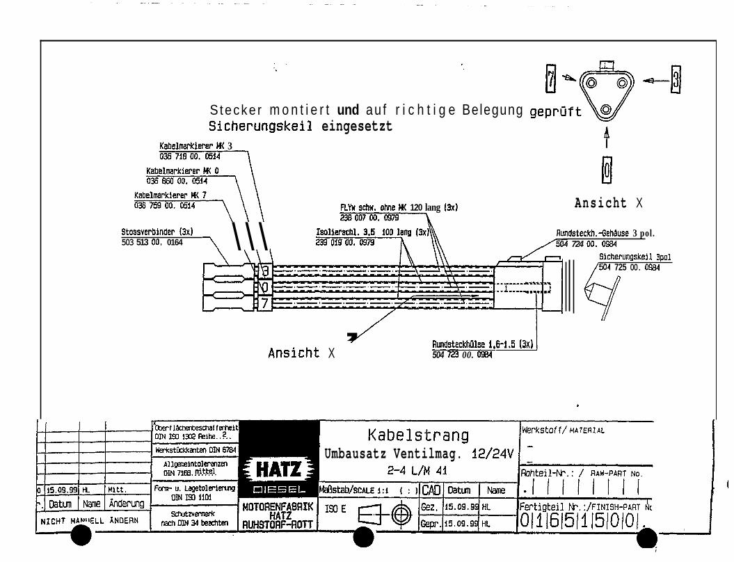
Stecke r m o n t i e r t und au f r i c h t i g e Belegung Sicherungskeil eingesetzt
Kabelmaskferer M 3
\ \ \ \ Stossverbinder (3x1 503 513 00. 0164
RYn schn. ohm u( 120 lang (3x1
239 Of9 00. 0979
Ansicht X
Aundsteckh.-GehAuse 3 pol. /5M 724 00. 0984
Sicherungskeil 3pOl /504 725 00. OW
/ Ansicht X ’ RundsteckhDlse 1,6-1.5 (3x1
504 723 00. 0984
Umbausatz Ventilmag. 12/24V
I

I !
mp connectors 0 Ed. 09, 9E
iNSTAtLAtlON PROCESS:
Cut off Ihe rnultiptug from wire-harness and crimp cable connectors h f y to adspfor.
CAUION: Mgke sure wire numbers matchiag mooer[
O f 6 609 00 msgne t valve
C = 501 707 00 all. screw M 6 x16
A = 039 380 I 0 magnet valve El = 016 51 5 00 hstallation kit
\
x = view yellow green
.... -..-. -"(7'F3' brown (0) 4

.. .-
0 0
0

*ION of FUNCTION: Position I(term.15) - The output term.87 is activated for approx. 15sec.(Tl) and the fuel valve opens and' remains open even if a failure signal exists at terminal SE. Position I I & 111 (term. 19 & 17) - The output term, 87 remains activated if the preheat and start phase is initated during the time period (T l ) . At the end of starting procedure and with the switch back at position I the time period T1 runs out and the relay supervises the engine. A failure signal(low oil pressure, high cylinder head temperature,etc.)which exists longer than 3sec.(T2), will ground out the relay, deactivate the term,87, allow the fuel valve to close and will shut down the engine. --mTz-
- DIESEL 50275800
m o 20A n SR185
TIMED DELAY - AUTO SHUTDOWN ---- u15
31 0 F p, CHARGE
0 87 OUTPUT 30
182
P - ACCESSORY 0 - OFF
:N SWITCH
I -I I - RUN - no flow c-- +- 159 -....--- Optional fault
signals. 4 1 I
B w qrp--jo I a 194 1 1 ENGINE PROTECTION
RELAY CIRCUIT
open open
START - STOP SOLENOID
CAD bLT0479 BE 10/29/98 4

ENGINE PROTECTION RELAY
DESCRIPTION OF OPERATION
When the keyswitch is turned to position 1 output 87 and timer 1 (Tl) are energized. T1 will hold output terminal 87 on for approximately 15 seconds, even though a failure signal exists at terminal SE. This ensures complete attraction of the relay and stop solenoid (attraction voltage 1OV) before a voltage drop is caused by starting (hold on voltage 6V).
If the engine is preheated or started during period T1, the relay will remain activated during these phases. At the end of these procedures, T1 is disengaged. The relay will remain engaged if there is no failure signal.
In case of a failure signal (oil pressure, temperature, etc.) which exists longer than 3 seconds T2 will cause the relay to de-energize and the engine will shut down.
DESCFWTION OF TERMINALS
Terminal 15 - Positive Input Terminal 3 1 - Ground Terminal 50 - Key Switch Input Terminal 87 - N.O. Contact (output to stop solenoid) Terminal 87A - N.C. Contact (output not used) Terminal SE - Failure Indication Input
INSTALLATION RULES
Installation Location - must be free of any vibration Installation Position - at convenience
TECHNICAL DATA
Max. perm. operating voltage VMAX Pull in voltage Vp Hold on voltage at terminal 15 VH Interference voltage at VB = 12 V Induction voltage Period of induction voltage Voltage peak Failure suppression 1 T1 Failure suppression 2 T2 Max. switching current 1 MAX (free of ind.) Max. resistance at SE R SE
Max. Resistance at 3 1 R 31
Voltage interr. after pilot impulse Perm. ambient temperature TM" Perm. ambient temperature TMAX
16 V 9.3 v 5.2 V 7.7 v 6 Vss/SO HZ 12 KV 100V/0.4rns every lOs, 50V/20s 8-15s 1.5-3s 20A 100 10 -~
2.5s -40 c +85 C
~

Testing Auto-Protection Relav Part Number - 50275802
The following procedure checks for the approximate 15-second start-up delay and also for the 3-second shut-down fault delay.
Tools needed: A). 12V test battery. B). 4 test leads. C). 1 test lead with indicator light.
Step One
A). Connect two test leads from battery negative to terminal “31” and terminal “SE” on the relay.
B). Connect a 12V indicator light from terminal “87” to the negative of the battery.
0 Step Two - TestinP the 15-second timer (Tl) in the relay
A). Connect a test lead fiom battery positive to terminal “15” on the relay. Note that the indicator light is now lit and will stay lit for approximately 8 - 15 seconds.
After the fight goes out this portion of the test is complete and the T1 timer is working properly.
Sten Three - Testing the 3-second fault timer (T2) in the relay
A). With everything connected as above:
B).With your last test lead, apply a positive 12V momentan, contact to terminal“50”. Note the indicator light is lit and will stay lit for approximately 3 seconds.
After the light goes out this portion of the test is complete and the T2 timer is working properly.

r n
F z
6
i-
s I= > a u1
ern I
I

Straavemwgung / Ladeeinrichtung Power supply / Charging device Alirentation clectr. / Charnew
Starteinrichtung Starting device I Otsnos. de derarr.
W t l i c h e Leitagen ohne Ouerschnittsangabe sind iz . A11 wires without conductor cross section data are 1' . Tout 1% cables sans indication de section sont de l2 .
Verdrahtung kundensei ts wiring done by custwer -----
Starter Protection Relay Part Number - 05062402 Kit Number - 01536900

-c I \ \
0 el

8. Miscefianeous (rev counter, hours meter, interference suppression)
important notes
Rev counter @Connect rev counter to terminal W of the 3-phase generator. @Use 8 rev counter to match the type of alternator concerned.
= Frequency or speed of alternator 7 Speedofengine = Number of alternator pole pairs = Transmission ratio between engine and alternator
. Revolution Counter
Bemerkung: fur 3/4L41C und 2/3/4M41: trotz D=138,8 der Scheibe 035 898 01 und d=63.8 der Scheibe 035 897 01 bei einer Profiltiefe von 2.lrnm beWgt die gemessene Ge-zahl 6350 mm-1 bei 3000min-1 an der 6lpumpenwelle. d am 2C41C iSt 71.8. -

Installation Instructions for L & M Two Speed Control Assembly
Part Numbers 12 Volt Solenoid - 00843802 24 Volt Solenoid - 00843902
2 Cylinder Mounting Kit - 00834902 3 & 4 Cylinder Mounting Kit - 00835002
See picture (1) for index and reference. Parts supplied in kit:
Quantitv 1 1 1 2 2 1 1 1 CI L 1 4
e
Description Part Number Console Bracket 00793100 Guide Bracket 01 141200 support 03650900 Tie Strap 50358400 Nut M8 50022900 Nut M5 50094300 Dwt Boot 50180400 Clamp 03924700 Spacer 031 16700 Pivot Block 0365 1520 Allen Screw M5X10 50049300 Electrical Wire Lead 01016500 Hex Bolt M6X30 50026000 Tension Spring 50324500 Roll Pin 4x16 50132000 Allen Capscrew M8X30 50268800 Lockwasher 8 50002800 Joint A2 1 X26 50001500
Note: The only difference between the 2 cylinder and 3 & 4 cylinder mounting kits is the design of the solenoid console bracket.
Pre-Assembly Instructions 1). If the solenoid console bracket is to be painted, do not paint areas were solenoid, console, ground wire lead and engine block come in contact with one another. Proper ground connection is required for correct operation.
-1 -

Installation Instructions for L & M Two Speed Control Assembly (cant.)
2). The solenoid is installed to the console bracket with three of the M5X10 0 allen screws. The ground wire (0) (supplied with the solenoid) is secured to the bracket with the bottom screw. The spring support (#lo) is installed with the middle screw. See picture (2).
3). Assemble tension spring to the guide bracket (#18) using the last M5XlO allen screw and M5 jam nut. The spring must move freely. See picture (2).
4). Lnstall guide bracket on solenoid using the two M8 nuts. One thread length of the solenoid control rod should protrude past the top jam nut. See picture (2).
Engine Preparation -
1). Remove throttle lever. Remove the top locknut and stud, wliich secures the throttle friction plate. Remove the lower two plate bolts. Note: On EPA certified engines, use a 4.5mm dia. drill to remove the locking plug in the lower left flathead capscrew. If this capscrew is damaged on removal, order P/N-50470800. Discard rubber bumper and remove plate. Remove any paint ikom the throttle shaft. See picture (3).
2). On non-EPA engines, discard the plate and install PM-03924700 clamp with the radius up and the bend facing towards the engine.
3). On EPA certified engines, modie the original fiction plate to look like the plate in picture (4). Install fiiction plate. The lower left flathead capscrew must have a new tamperproof plug installed, order P/N-04 128900.
Final Installation 1). The solenoid mounts on the engine at the oil fill tube. Remove and discard the old oil fill tube mounting bolts. Note: Do not disturb or damage the oil fill tube gasket or oil leaks may occur.
2). Install the solenoid with the M8X30 capscrews, #8 lockwashers and the two P/N-03 1 16700 spacers on the backside of the console. See picture (5). Plug the ground (0) and speed hold winding (14) wires into the solenoid. Install long wire through proper looming to switch control point.
-2-

Installation Instructions for L & M Two Speed Control Assembly (cont.)
3). Set proper high and low speed settings. On EPA certified engines, the high-speed setting is tamperproof. Attach spring to guide bracket as per picture (6).
4). Install the 4x16 roll pin into the Phi-03651520 pivot block, the roll pin protrudes out of the back side of the pivot block when the M6X30 hex bolt is on the right side of the throttle shaft. See picture (7). The roll pin must go through the slot in the guide bracket and contact the throttle assembly.
5). With the engine running at full throttle, energize solenoid. See picture (8). Tighten hex bolt on pivot block. Re-check for proper operation and speed settings. Do not adjust high-speed setting without re-adjusting pivot block. Solenoid must always be at end of stroke for proper operation.
6) . Insert the A21X26 copper joint into the large end of the dust boot for support. Install dust boot over the throttle shaft with the large end facing away firom the engine. Push on until boot meets pivot block. Use the wire ties to secure the electrical wire at convenient points.
09-16-99
-3-

Picture %dex # Description Part Number
EPA Friction Plate 04 13 1800 8 Clamp 03924700 3 Modified EPA Friction Plate 4 Joint A2 1 X26 5000 1500 5 Dust Boot 50 180400 6 Electrical Wire Lead 0 10 16500 7 Roll Pin 4x16 50 1 3 2000 8 Pivot Block 03651520 9 Hex Bolt M6X30 50026000 10 Spring Suppoit 03650900
Picture Index #
11 12 13 14 15
16 17 18 19 20 21
Description Part Number Nut M8 50022900 Allen Screw M5X10 50049300 Nut M5 50094300 Tension Spring 50324500 12V Solenoid 00843802 24V Solenoid 00843902 2/3/4 Cyl. Console Allen Screw M5X10 50049300 Guide Bracket 01 141200 Lockwasher #8 50002800 Spacer 03 1 16700 Allen Screw M8X30 50268800
Picture (1 )

i . ’ .. .
-Step 2-
a
Picture (2) -Step 3-

Picture (3)

I Picture (4)

Picture ( 5 )

Picture (6)

Picture (7)

Picture (8)

HATZ Diesel Engines
I D .. SUPRA m L41 C SILENT PACK
m M41
With the NEW electrical equipment for Man Lifts
Complete Starter Protection from Accidental restarting of engine
Less down time
1

0 Electrical protection against starter engagement during operation and Electrical protection against starter engagement up to complete engine stop.
From now on, HATZ Diesel Engines can be equipped with a new electrical system which consists out of a control part (Instrument Panel) and a load part (Power Box).
This new electrical setup does not only avoid restart of a running engine (Starter damage, Ring Gear damage, down time ...), it also senses any movement of the ring gear, which means that an engine slowly spinning to stop is electronically protected against restart and avoids damages due to starter re-engagement into a still rotating ring gear.
With this equipment from HATZ, the engine will offer a higher degree of reliability. The small cost for this equipment will pay for its self, in less down time and maintenance problems and increased customer satisfaction. 0
.-
The main components are explained on the following pages.
2

The Power Box 0 is the main switching station for all load devices. It is mounted along side the flywheei housing.
The relatively high current for the starter solenoid, motor, and glow plug system are activated within the power box, with very little voltage drop. @ Relays, @ Removable fuses.
In the past without any relay box, the wiring was heavier & limited to 2-3 meter with a larger voltage drop.
The harness can now be much longer than in the old electrical system.
Easy plug connectors @ are located at the engine
3

I
I The electrical connector 0 can be protected from dirt, moisture, and crrosion with a cover 0.
4

The starter protection relay @ is a standard feature to prevent restart on the key switch.
This feature is in addition to our anti-restart key switch.
The starter protection relay is integrated into the power box.

The starter protection module 0 is specially used where the customer cannot hear his engine running. Especially important in the lift industry.
The starter protection module is used to sense engine revolution down to zero.
The module allows only restart with no engine movement for about 8 seconds.
The starter protection module is the only reliable device to protect the starter from mis-engaging.
6

I Automatic Shut Down I
The shut down control panel includes the relay for the auto shut down feature.
This shut down control monitors cylinder head temperature and oil pressure and reacts if the tolerance limits are exceeded.
The starter protection relay has a timing circuit to protect against false signals and false shut down.
7

n
The glow start timing circuit 0 senses temperature and allows for a longer or shorter glow time depending on ambient temperature.
The key switch turned to "On" will start the timing for the glow process. When the indicator light @ goes off, the engine can be started.
The relatively high current for the glow plug at approximately 55 amps runs through a relay @ which is mounted to the engine and protected by a fuse @.
HATZ Diesel engines require pre heat only if the temperature is below -15°C (5°F)
8

The shut down solenoid 0 is mounted on the mechanical oil pressure shut down device 0. The solenoid is activated during operation (when key switch @ is turned on). Deactivation of the solenoid will shut the engine down immediately.
The powerbox makes an engine shut down from a remote position possible.
9

I
I
6.5 ft
1
10 ft
I
10 ft extension
Standard harnesses available
10

Relay Type Function ~ 5E RVIC E
Load switch relay
New L/M 41 Electrical Circuit Relays
0 A). Start operation of starter solenoid 6). Load circuit for pre-heating
C). Stop operation of starter solenoid THE POWERBOX CONTAINS THESE RELAYS!
device
Timing relay An additional three second delay for the start-up of four cylinder engines after the shut-off of the starter solenoid signal. The timing relay is part of the new instrument box for automatic shut-off.
Engine protection relay The engine protection relay is a combination of the load switch and timing relay. It is used for the auto- matic shut-off due to low oil pressure or overheating. The engine protect- ion relay is part of the new instru- ment box for automatic shut-off.
’. Starter protection module The starter protection module in
conjunction with the load switch relay prevents the re-start of a running engine. From 600 rpm to 0 rpm plus a safety period. The starter protection module is installed on the engine and the load switch relay is located in the POWERBOX.
6-28-99

*
v)
CD
x a l o x c n n
.- - I
-I a c(
w c 4 I
2 %- 0 U cn Y L I 2

^ - A -
' T t - M h
I l l I 1 I
Mu tor Engine Mloteur
I i i i
.- i
Armaturenkasten m i t Anteige
Instrument box with indication
Boitier de bord avec indication
Armnt w e n k a s ten instrument box bo 1 t I (!r fie bord w-.: tur Power box to [ IOWt ' f ' t,ox boitier u t b f'f 'lais
to nower D O X b01tler cle relais wEwrrr.:
Motor E ngirie
Stromlaufplan -̂-

Power Boxes and Lnstrument Panels for HAT2 M41 & LA1 Series
0 1610700 Panel #2
Power Box and Mounting
0 1608800
Indicators only. not for shutdown or glow plugs. Note: Replaces # 00817702. Used for auto shutdown and
Power box # 1 used for all M & L engines.
01614200* 2M length (6.6 feet) Note: # 14 wire included for 2 -speed. 3M (9.8 feet) harness (special application). 2M extended harness, has connectors on both ends for easy connection to power box and to instrument panel.
01653400
0161 1600
0 1609000
Murphy panel or customer panels using HAT2 loose key switch and electrical relays. For customer panels (power box required). Extends instrument panel hrther from power box.
~-
0 1608600*
50366200 50148000
0 1608700
Power box #3 used for all M & L engines.
Mounting p& for power box. (For M series only).
Studs (3) Nuts (3)
Mounting parts for power box. (for L series only).
* Included on sales standard engines.
0 Instrument Panels Part # Descriotion
Used for all instrument panels and glow plug.
Special use only, used exclusively with the Zero RPM module.
Bracket bolts to side of bell housing, and has power cable fiorn starter to electrical terminals on bracket. Required for remote fie1 filter mounting, M series.
Mounts power box to bell housing. ( Bracket &hardware) Positive & negative are provided on w s u l e housing.
Used With
Used For
Instrument panels shown below.
Zero RPM module. (Consult Factory) Factory mounted
part # 01642700. For power box and for customer supplied instrument box. Positive & negative terminals provided. Used with power box mounting kit # 01608600.
Used with power box.
for glow plugs. Note: replaces # 00824603.
4/6/00

Anlage ZU
Annex 4.1.1 'a" WSI 2000.162 Annexe Anexo para
Kabelnummem Lead numbers zum Armaturenkasten
to switch box vers boitier de commande
por cuadro de mando Numbros de cables Numeros de cables
Laufende Nr. der Steckerplatze Current numbering of co No. d'ordre sur le connecteur No. comelativo sobre el conector
turn Motor to engine
vels moteur por motor
Power Box I 12 v 2 - 4 LIM 41
Ident-Nr. auf dem Typenschild Ident-No. as indicated on label No. ident sur la plaque signalktique No. ident sobre la placa signaletica
Ed. MSS-schi-es 12, 99 01 597900,1023

Kabeinummern Lead numbers Num6ros de cdbles Numeros de cables zum Armaturenkasten
lo swilch box v e n boitier de oomrnande Laufende Nr. der SteckerplBtze \ por cuadm de mando
Current numberina of connector locations @$?@@PP 4@@P@P , No, d'ordre sur le zonnecteur
+ No. correlativo sobre el conector
for Verwendung mit Starterschutzmodul I for use with stitter protection module I avec module de protection demarreur I Dor modulo de protecci6n arranque
t u r n Motor to engine
vefs moteur por motor
Ident-Nr. auf dem Typenschild Ident-No. as Indicated on label No. ident sur la plaque signalhtique No. ident sobre la placa signaletica
I
Ed, MSS-schi-es 12,99 01591000,7023 0 0

c I c o
0 0 0 0 0
0 Q a a 4 - g
X a J o x c 330

I I Arnat ureaasten lnstrmnt box
?.5 2.Y Boitler de b o d A5
Armaturenkasten mit Vorglfih- , und Abschaltautomatik
_ - Instrument box with preheating and shut o f f automatic
Boitier de bord avec prechauff
ho
6.0 X x n b vv" ~ Q I et arret automatique
instrument box hni t i ~ r dP horf l
zur Power box to [ I f I W t Y ' box
- A t u r Power box t o power box *
b o t t l e r (1c relais
Uotor Engine
Standard m i t Abschaltaut.

= nicht belegt / not applied /
Lead numbers NUiii6iaS de cables Numeros de 10s cables
Anlage ZU
3.1 .I WSI 2000. I62 Annex Annexe Anexo para
Nummemreihe auf Gehguse Numbering on plug housing Num6rotation sur le connecteur
SteckhUlsen (female) sockets prise femelle manguito de enchufe
Ed. 12, 99 MSS-schi-es
Steckstifte (male) pins prise male pemo de clavija
Armaturen kasten Switch box Boitier de commande Cuadro de mando
I 4 2 V
Ident-Nr. auf dem Typenschild Ident-No. as indicated on label No. ident sur la plaque signalbtique No. ident sobre la placa signaletica
01 551 802, 1 003
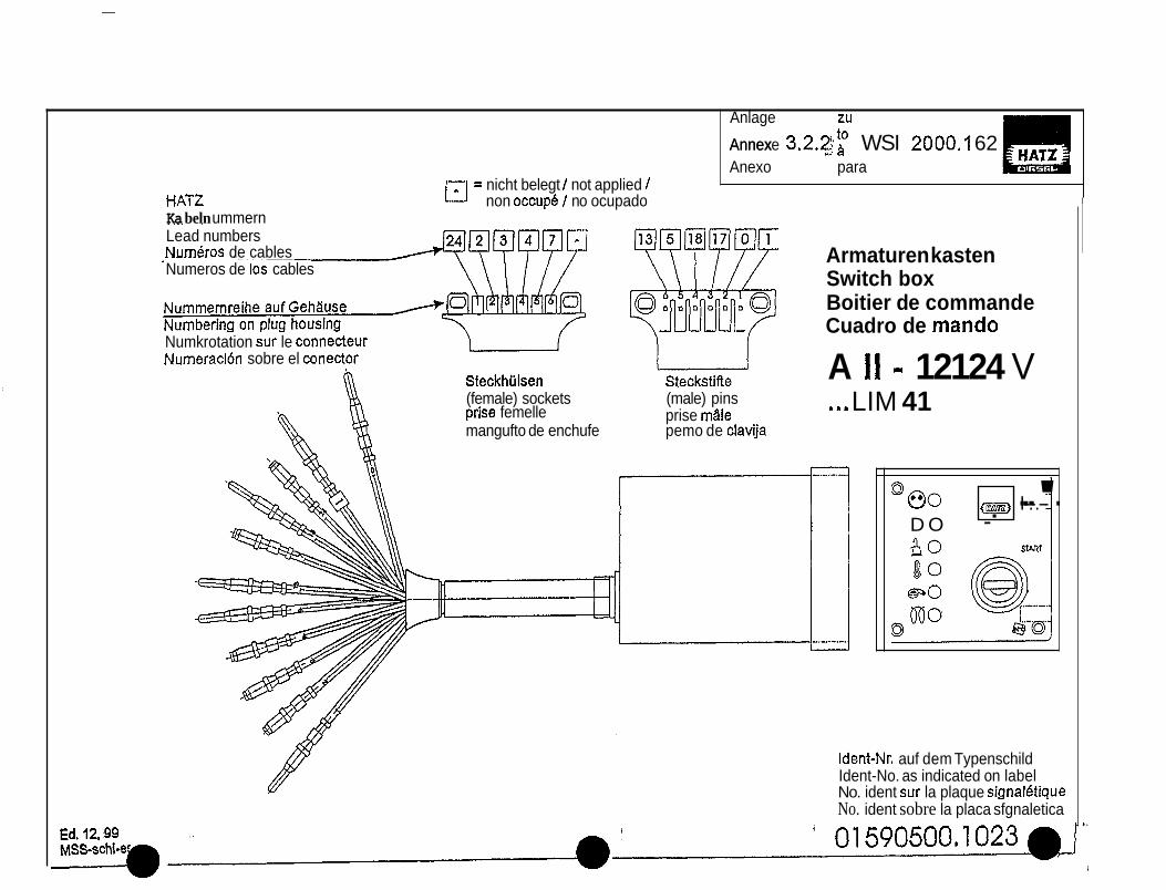
Anlage ZU
Annex Annexe 3.2.2;; >I WSI 2OOO.A 62 Anexo para
r-7 = nicht belegt I not applied I HAT2 L-J non occup6 I no ocupado Ka beln ummern . -. Lead numbers Numkros de cables Numeros de 10s cables
Numkrotation sur le connecteur Numeraci6n sobre el conector
SteckhUlsen Steckstifle (female) sockets (male) pins
prise mi le prise femelle mangufto de enchufe pemo de clavija
Armaturen kasten Switch box Boitier de commande Cuadro de mando
A I I - 12124 V LIM 41 s m s
I I-.-.-- 80 _. ---'- D O
I
Ident-Nr. auf dem Typenschild Ident-No. as indicated on label No. ident sur la plaque signaletique No. ident sobre la placa sfgnaletica

INDEX H.D.A. WIRING DIAGRAMS
03852303
03 852303
03 852303
03 852303
03 852303
1 Engine 1 Description 99400347
99400348
99400369
99400349
99400350
L & M
2 & 3 Cyl.
2 & 3 Cyl.
4 Cyl.
4 Cyl.
4 Cyl.
4 Cyl.
2 & 3 Cyl.
2 & 3 Cyl
Standard Panel w/Temp Sw.
Standard Panel w/Temp. Sw. & G.P.
Standard Panel w/Temp. Sw. & G.P. & 2 Speed
Standard Panel w/Temp. Sw. & 2 G.P.
Standard Panel w/Temp. Sw. & 2 G.P. & 2 Speed
Auto Shut Down Panel w/T" Sw. & 2 G.P. & 2 Speed
Auto Shut Down Panel w/T" Sw. & 2 G.P.
Auto Shut Down Panel w/T" Sw. & G.P.
Auto Shut Down Panel w/T" Sw.
L & M Standard Panel wflemp. Sw.
03852603 994003 5 1
b
HatzNo. I HDA
8 & G.P. & 2 Speed
Auto Shut Down Panel WE" Sw. L & M 03852603
I 03852603 I 99400366
994003 54
03 852403
03852703
9940067 1
99400672
I
2 & 3 Cyl.
4 Cyl.
2 & 3 Cyl.
November 25. 1997
Auto Shut Down Panel w/Temp. Sw.
Auto Shit Down Panel wfTemp. Sw. & 2 G.P. Auto Shut Down Panel
w/Temp. Sw. G.P.

511 I I I 1 126 127 129 151 159 161 162 170 182 194
INSTRUMENT PANEL WIRING
7
0 B2.i wf 4 1 I t
WIRING
.) STANDARD
WIRING DIAGRAM L & M ENGINE
PANEL w/TEMP, SWITCH 99400347

/ d r w I
I N S R U M M PANEL WIRING
MI- R M Y 151
I L 2
ENGINE WIRING W I Ri NG DIAGRAM
2&3 CYL, L & M ENGINE STANDARD PANEL w/ TEMP. SW. & GLOW PLUG & SPEED CQNT'L SOLENOID,
9 9 4003 69

e 0- -m r
f " I
j
1
i I d
i 1
1 1 -c qEl* m 129
r4
INSTRUMENT PANEL WIRING
ENGINE
m 1510
1 21 123 126 127 17.9 151 159 161 162 170 182 184
WIRING DIAGRAM 2&3 CYL, L & M ENGINE STANDARD PANEL w/ TEMP, SW. & GLOW PLUG
99400348

P

I
I 1 WPS
1 I": 121 123 126 127 129 1510 l51b 159 161 162 170 172 179 182 190 194
HI I I
I I I lri I - INSTRUMENT PANEL WIRING
1 ENGINE
WIRING DIAGRAM 4 CYL, L & M ENGINE STANDARD PANEL w/ TEMP. SW, & GLOW PLUG & SPEED CONT'L SOLENOIC

1 I

1
I
I P 1 I ' I
L
msHvIDM( rmED WAY
INSTRUMENT PANEL mmRE22cmNJ.m lAcmmERm WmaUroRTERUiW. WIRING - - - - - - ------
WIRING DIAGRAM 4 CYL. L & M ENGINE AUTO SHUTDOWN PANEL w/ TEMP. SW. 8 GLOW PLUG
121 123 126
129 1510 l5 lb 159 161 162 170 1l3 tn 182
in
194 sHuTwyo( SCN.EW6
SOLaKRD 99400352 --.

I I I I
I
I I / I I I--l I
INSTRUMENT PANEL WIRING
------ ENGINE WIRING
m 1. lorM 4n f 3" 011 ~ W l l E L W S U I O T -
ammlSmAILIILD. t . m m r m m m
WIRING DIAGRAM 2&3 CYL. L CJC M ENGINE AUTO SHUTDOWN PANEL w/ TEMP, SW. & GLOW PLUG
99400353 ,. ,

-

I P
. ..
i I.
i
e
r 1 1 I
I
I II
’!1 d
I - I
im . t tmxznlrrrrrsa rmnancpmcum INSTRUMENT PANEL
WIRING ruakaatw4v.
WIRING DIAGRAM L & M ENGINE AUTO SHUTDOWN PANEL w/ TEMP. SW.
= / I

\
I I I I
1 1 I
I ‘ I
1. i

w

_I W z a a
' I I t
1

.9-
* I , @ 1 23
GLOW PLUG NDIUTOR/
58 xl IS 19 I 7 P - ACCESSORY
I - RUN 1 - PREHUT SPRING RE- lU - STAN [TURN TO I
KM WCH 112
STARTER PROTECTlON
GLOW PLUG
-ID no flew
INDICATOR DIODE GROUND ' lAMP
STMT - STOP SOLENOID 99400674
EM1
R E F 03852703 BE 10/17/97

ELECTRICAL HARDWARE PARTS
LIST
HATZ DIESEL OF AMERICA, INC. W229 N1645 WESTWOOD DRIVE
P.O. BOX 258 WAUKESHA, WI 53187-0258
August 2000
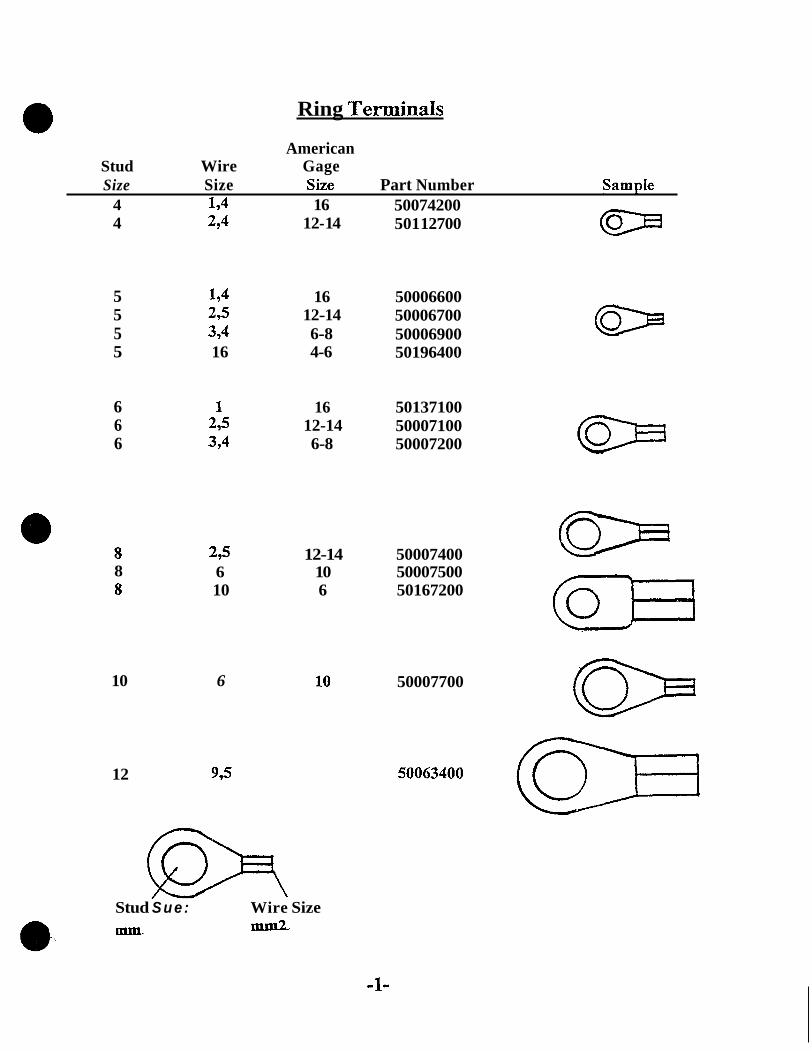
Ring Terminah
American Stud Wire Gage Size Size Size Part Number Sample
D 4 194 16 50074200 4 294 12- 14 501 12700
5 194 16 50006600 5 295 12-14 50006700 5 394 6-8 50006900 5 16 4-6 50196400
6 1 16 50137100 6 295 12-14 50007100 6 394 6-8 50007200
8 8 8
10
295 12-14 50007400 6 10 50007500 10 6 50167200
6 10 50007700
12 995
Stud S u e : Wire Size mm.
-1-

Terminals
Butt Connector PM - 50189200 - 15 x 1mm cI--D
Open Barrel Tab Terminals
Locking Tab - Female “A” Terminal P/N - 50331 100 - 6.3 X 1mm MITl/-7
- &qJ 6 P/N - 40074700 - 6;3 x 1-4mm P/N - 50196700 - 6,3 X 6mm
Locking Tab - Male “B” Terminal P/N - 40103200 - 6,3 X lmm P/N - 40098700 - 6,3 X 1-4mm
L KF] 0
G Locking Tab - Female “C” Terminal P/N - 50276800 - 9,5 X 6mm
u Female - “D” Terminal
WII-J P/N - 40043200 - 6,3 X 194mm PIN - 50162000 - 6,3 X 6mm
Male - “E” Terminal P N - 50184000 - 6 3 X 1-4mm
TvmG- 0
cz) Dual Locking - Female “Fn Terminal P N - 50350100 - 6,3 X lmm P/N - 50350200 - 6,3 X 2,5mm
0 Open Barrel Type - Female and Male “G” Terminal & g pm - 50135300 - 6,s x 1-4mm
@Q=.-c3 Locking Tab - Female 4‘H’’ Terminal P/N - 50157500 - 3,2 X 1-4mm G
-2-

Pin dk Socket Terminals
Pin - “I” Terminal P/N - 50374100 - 2,5 X 2,5mm PM - 50374300 - 2,5 X 2,5-4mm ‘
Socket - “J” Terminal P/N - 50373800 - 23 X 0,5-lmm ”- P/N - 50373900 - 2,5 X 1,5-2,5mm P/N - 50374000 - 2,5 X 2,5-4mm
3
Pin - “K” Terminal P/N - 50351000 - 1,5 X 0,75-1,5mm
Socket - “L” Terminal PM - 50350900 - 1,5 X 0,75-1,5mm m
Pin - “M” Terminal pz P/N - 50352600 - 3,5 X 2,5-4mm
Socket - “N” Terminal P/N - 50352500 - 3,5 X 2,5-4mm -1
Spade - “0” Terminal .(Murphy Gauge Panel Terminal) * P/N - 99400198 ~ PM - 99400199
Pin - “P” Terminal (Princeton Forklift Terminal) PN - 50393700 - 3/32 X 16g.
Spade - “Q” Terminal (Princeton Forklift Terminal) P/N - 50393800 - % X 10-14g.
[-I Socket - “R” Terminal PN - 50472300 - 1,5 X 1,0-1,5mm
Pin - “S” Terminal P/N - 50407000 - 1,5 X 1,0-1,5mm I
-3-

Connector Plugs
P/N-50379700 Uses “I” Terminals 1
@ U N
0-
P/N-50373600 Uses- “I” Terminals
PAY - 50402000 Uses “I“ Terminals
PAY-50351200 Uses “K” Terminals
P/N - 50498500 Uses “S” Terminals
PIN - 50379800 Uses “J” Termipals
P/N-50373700 Uses “J” Terminals
P/N-50402100 Uses “J” Terminals
P/N-50351100 Uses “L” Terminals
P/N-50472400 Uses “R” Terminals
-4-

Connector PIYES
Phi-40103300 Uses “A” Terminals
Phi - 40103400 Uses “A” Terminals
e P/N - 50324600 Uses “An Terminals
P/N-50276700 Uses “A” Terminals
P/N - 40098800 Uses “B” Terminals
P/N - 40103500 Uses “B” Terminals
-5-
P/N - 50324700 Uses uB” Terminals
P/N - 50276600 Uses “C” Terminals

Connector P€um
P/N-50190700 Uses “D” terminals
P/N-50350300 Uses “F” Terminals
PIN - 50352700 Uses “M” Terminals
P/N-503528OG Uses “N” Terminals
P/N - 99400196 Uses “0” Terminals For Murphy Gauge Panel
P/N-50283900 Uses “A” Terminals Voltage Regulator Plug - 70 Series
-6-
P/N-99400197 Uses “0” Terminals For Murphy Gauge Panel
P/N-50159011Socket PIN - 50159100 Nut
101 I I
P/N-50434000 Uses “A” Terminals

Pigtail Assemblies
P/N - 01651500 Complete Pigtail Assembly
Fuses
I0 amp - P/N - 50459300 30 amp - P/N - 50430700 40 amp - P/N - 50433000 0 20 amp - P/N - 50486900
50 amp - PM - 50485400
-7-

Fuse Holders
P/N - 50485900 Mounting Bracket (on backside of fuse holder) with P/N - 50485800 Fuse Holder
P/N - 50485800 Fuse Holder
-8-

L-l
Relays and Bases
kelay 12V 20/30A P N - 50277701 !4V 10/20A P N - 50277801
Relay 12V 70A PN-50432700 24V 40A P/N-50454000
Relay 12V 20/30A P/N - 50162100
-9-
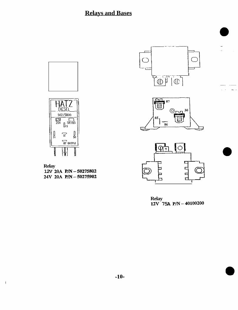
Relays and Bases
so ' a 87 OUlPUl
Relay 12V 2OA P/N-50275802 24V 20A P/N-50275902
I I I l l I I I
OeJ
Relay 12V 75A P/N-40100200
-10- I

Relays and Bases
I: I
Relay Base
Uses “A” Terminals To be used with: 12V 20/30A P/N - 50277701 relay 24V 10/20A P/N - 50277801 relay
P/N - 50276000 Relay Base
To be used with: 12V 70A P/N - 50432700 relay 24V 40A P/N - 50454000 relay
P/N-50432800
-1 1-

Indicator Lights
Light Socket Assembly
/
P/N-40009700 12V-2W P/N - 40009800 24V-2W
Symbol
+
Charging Indicator Socket PN-50176500
b w QiLPressure Socket P/N- 50176600
High Head Temperaturesocket P/N - 50176400
Diodes
P Diode Assembly - Length = 90mm Diode
P/N-50344400 Diode M8 X 1.25 Thread p, - 01178700 P/N-40027900
Diode Assembly - Length = 185mm P/N - 01150101 Diode Assembly - Length = 320mm
P/N - 01154901
-12-

Cable Fastening Hardware
Insulated Cable Clamps
Bolt Hole Size Clamr, Area Part Number M6 lOmm 50 173500 M6 14mm 50 158400 M6 21mm 50190310 M8 21mm 50 1970 10
Non-insulated Cable Clamps
Bolt Hole Size Clamp Area Part Number M8 12mm 03 165500 MI0 12mm 03538000
Wire Ties PM-40092700 120mm long X 5mm wide
PM-50358400 180mm long X 5mm wide -
P/N-50167400 s) 290mm long X 5mm wide
0
Rubber Components
Rubber Boot P/N-40026700
c Rubber Boot P N - 40026600
Rubber Sleeves P/N - 50160300 2mm dia. X 20mm long P/N - 50160500 3mm dia. X 25mm long
- 13-

LETTER SYMBOLS AND ABBREVIATIONS
A
ac
Ah
Alt
am
amp
amp1
assy
auto
aux 0 avg
AWG
B
B
B+
B a t t
C
C
- Ampere
- Alternating current
- Ampere hour
- Alternator
- Ammeter
- Ampere
- Amplifier
- Assembly
- Automat ic
- A u x i l i a r y
- Average
- American W i r e G a u g e
- B a s e
- B a t t e r y terminal
- Positive battery terminal or w i r e
- B a t t e r y
- Capacitor
- Capacitance
-1-

C
cal
cap
Qm
Cmil
CMOS
dB
dc
D F
D F
D i s c
D-
a? dPdt
apst
D+
dt
DTL
LETTER SYMBOLS AND ABBREVIATIONS (cont.)
- Collector
- Calibrate
- Capacitor
- Centimeter
- Circular m i l
- C o m p l e m e n t a r y m e t a l - o x i d e semiconductor
- D e c i b e l
- D i r e c t current
- Alternator field terxninal or w i r e
- Generator field terminal or w i r e
- D i s c o n n e c t
- G r o u n d terminal or w i r e
- Double-pole
- Double-pole, d o u b l e - t h r o w
- D o u b l e - p o l e , s i n g l e - t h r o w
- Alternator excitation terminal or w i r e
- D o u b l e - t h r o w
- Diode-transistor logic
-2-

LETTER SYMBOLS AND ABBREVIATIONS (cont.)
DVOM - Digital voltohm meter 0 E - Voltage
E - Electromotive force E - Emitter F
fb
FET
f il
fu
G 0 G
G
G
- Farad (Capacitor value)
- Fuse block
- Field-effect transistor - Filament
- Fuse
- Generator - G r o u n d
- Gelb (yellow)
- Giga (lo9)
- Wire gauge
- G r o u n d e d
- G r o u n d
- High voltage
- Hertz
-3-

I
I
IC
incr
ind lp
inp
insp
inst
inst
instr
insul
insul
jb
jct
K
KA
kV
kW
LETTER SYMBOLS AND ABB€UWIATIONS (cont . ) - Current - Input
Integrated circuit
Increase
Indicating Lamp
Input
Inspect
Install
Installation
Instrument
Insulate
Insulation
Junction box
Junction
mi0 (lo3)
Kilohm (1,000)
Kilovolt
Kilowatt
-4-

LETTER SYMBOLS AND ABBREWIaTTQNS (cont.)
@ lim sw - L i m i t q c h
lr
M
M
m
-
M
38
mA
ms
mV
mW
n
N-m
nc
nc
nc
- Load resistor
- Mega (lo6)
- Motor
- Meter or Milli
- Megohm (1,000,000)
- Square meter
- Milliamp (-001)
- Magnet
- Millimeter
- Square millimeter
- Millisecond - Millivolt (.001)
- Milliwatt (-001)
- NEUIO
- Neuton meter
- Normally closed - No connection
- No coil
-5-
LETTER SYMBOLS AND ABBREVIATIONS (cont.)
neut
no
O P r
out
P --
P -
PC
PF
Ph
POS
Pwr
R
res
re-ct
rgltr
r l Y
r p m
S
- N e u t r a l
- N o r m a l l y open
- O p e r a t o r
- Output
- P i c 0 (lo-'')
- P o l e
- P r i n t e d circuit
- P i c o f a r a d
- P h a s e
- positive (+)
- Power
- Resistance
- R e s i s t o r :
- R e c t i f i e r
- R e g u l a t o r
- R e l a y
- R e v o l u t i o n s per minute
- Signal p o w e r
-6-

S -
sig
snsr
sol
sw
t sw
t
t
tb
tm
TTL a v
- Second (time)
- Signal
- Sensor
- Solenoid - Switch
- Temperature switch
- Temperature - Time - Terminal board
- Temperature meter
- Transistor-transistor logic
- Volt - Vacuum - Voltmeter - Voltage regulator - Watt - Winding - Wire gauge - Wattmeter
-7-

LETTER SYMBOLS AND ABBREVIATIONS (cont.)
wrg - Wiring wtrprf - Waterproof
- Micro
- Microamp (.OOOOOl)
- Microfarad ( . 000001) - Microvolt - Microwatt
-8-

FIU.EL SYSTEMS.
. .
Sedan Urmugh 1Jrpe P f 3 t K. I DeNvsrynlve holder. 2 Ddivsry valve. 3 Pump barrsl. 4 Pump plunger. 5 Contml m a 6 Coml slssva 7 Plunger contml urn 8 Roller capper.

L/M Series Fuel SVstem
I I
I

FUEL CIRCUIT

. NCZZLE BODY
INJECTOR
1
Shim 6 c3>
Spring 5
spring -I Q Seat
Intermediate Piece
Nozzle - I
! d I .
Nozzle Holder

NO-ZZLE AND HOLDER ASSEMBLY
1 I 6
7
8
9
10
11
12
13
1 Inlet, 2 Holder body, 3 Pressure channel, 4 In- termediate disc, 5 Nozzle-retaining nut, 6 Union nut for fuel-injection tubing, 7 Edge-type filter, 8 Leak-off porr, 9 Pressure-adjusting shims, 10 Pressure spring, 17 Pressure spindle, 12Locat- ing pins (locating the nozzle), 73 lnjection nozzle.

Nozzle-Holder Assembly Operation
The nozzle-holder assembly is used for fastening the injection nozzle in the cylinder head of the 0 engine. It establishes the connection with the injection tubing and contains a spring which determines the nozzle-opening pressure.
Construction The nozzle-and-holder assembly consists of the nozzle holder and injection nozzle together. The nozzle holder consists of the holder body, intermediate disc and nozzle-retaining nut as well as the pressure spindle, pressure spring, pressure-adjusting shims and locating pins (not in the case of pintle nozzles.
The injection nozzle is fastened centrally in the holder body with the nozzle-retaining nut. When the holder body and the nozzle-retaining nut are screwed together the intermediate disc is pressed against the flat face of the holder body. The pressure spindle, pressure spring and pressure-adjusting shims are located in the holder body. The pressure spring is guided by the pressure spindle while the pressure spindle itself is guided by the nozzle needle.
In the holder body the pressure channel leads to the inlet bore of the nozzle body and thus connects the nozzle to the fuel-injection tubing of the injection pump. Depending on the area of application of the nozzle holder an edge-type filter may be installed in the pressure channel of the holder body.
Operation The pressure spring in the holder body presses on the nozzle needle via the pressure spindle. The initial tension of this spring determines the opening pressure of the injection nozzle. The opening pressure is adjusted by means of pressure-adjusting shims. The fuel reaches the nozzle seat via the respective inlet bore in the holder body, intermediate disc and injection nozzle. During injection the injection pressure lifts up the nozzle needle and the fuel flows into the combustion chamber through the blind hole and the spray holes. When the injection pressure drops the spring forces the nozzle needle back onto its seat, thus terminating the injection of fuel.
I
I

Injection Pump Operation
c Plunger-stroke phases
I Sotiorn 2 Prestroke 3 Retraction 4 Effkclive 5 Residual 6 Topdead deadcenter1 I stroke 1 stroke 1 stroke I center ( B W croc)
1 L
Fuel Rows from the injec- tion pump's fuel m e w and into the high-pressure chamber of the plunger- and-barrel assernw.
V
IL t x
Plunger stroke from 8OC to dosure of the inlet port by
top edge of the plunger (variable de- pending upon plunger-and- barrel ==nblY).
Plunger strokc from end of the prestroke until the deli- very valve opens (only if a constant- volume valve is used).
L 7
Plunger stroke from opening of the delivery valve to open- ing of the inlet port by the plunger helix (overflow).
Plunger strokc from opening of the inlet port to TDC.
Reversal of plunger travel.
A Totalstroke
.. Figure4 Page# 08 - 13 Issue 1
August 1, 1997

Injection Pump Delivery Control
Fuet-deliveiy control Using a toothed control rack. a) Zero delivery, 6) Partial delivery, c) Maximum delivery. I Pump barrel, 2 Inlet port, 3 Pump plunger, 4 Helix, 5 Control rack.
I 2 3
a b
Y-----f C
Figure 5 Page# 08 - 14 Issue 1 August 1,1997

Executions'of direct injection (multi-hole) nozzles
A
Standard sac-note nonie
1 D 30 - 35 - 40 -60- 80 2 G... j Z 7... L / M 3 0 - 3 1 -40
B c
Sac-hole nozzle wfth reduced sac-volume
1 D31 /41 1 D81 1jm41
5e43
06/12/97
Seat-hole nozzle
Ed. 09, '96 MSS-sChl-es

FUEL PUMP
Piston style fuel pump P/N 50242400 Used with JET FUELS
Pressure range ApproX. 40 p.s .1 . (2.75 bar)
JP48 JP58 &3P8
Diaphragm style firel pump
Used with DIESEL ECFELS: Diesel 1 and Diesel 2 Pressure range of approx 4 to 6 p.s.i. (0.3 to 0.4 bar)
P/N-01562700

-
INSECTION PUMP
Delivery Valve Holder
5 Delivery Valve Spring
a 6 Copper Washer 3 Delivery Valve
Banjo Bolt i7
Stop i 6 Wire
Retaining Pin
2 Barrel and plunger assy.
12 Gear
8 Spring Seat
70 Spring
9 Spring Retainer
13 Roller Assy -
..

On the subject of injection pumps:
Why individd injection pumps ?
The logistic actvantages - One 8hgle type of p u p : A l l types of engines from these series are equipped with the same injection p u p irrespective of the power and speed, - One single type of governor: Easily adjustable to all control requirements. control governor, - One single type of preaswce pipe for all cylinders: The ex- tremely short lengths of lines are an additional advantage - the pumps are installed directly in front of the cylinders. More precise injection for the entire range of speed and load, results is economic use of the fuel with the minimum thermal and mechanical loading of the engine.
All engines are equipped with the same speed
The
The service admntages -No special tools or special knowledge is necessary for the ex- change of injection pumps, - The the takn for the exchange of pumps is 1/3 of the the necessary for in-line pumps. - The danger of incorrect fuel adjustment, exhaust and noise emission is eliminated by a simple exchange- - New or exchange pumps are ready for installation. The previous adjustment at the test bench is unnecessary because full load and speed are adjusted on the engine, - Immediate availability, because of the low cost of storage the injection PUMPS may be stored by the user himself. In-line pumps are usually not stored for economic reasons but are repaired. This could mean considerable waiting times. - In the case of failure of one pump element only this individual pump must be changed. - In the case of in-line pumps, all elements must be changed and and the engine is out of action.

'phs financial actvantages - Three new injection pumps for a three cylinder engine cost approx. 40% of a corresponding in-line pump. - When only one element is faulty the costs are reduced to a third f o r the injection pump. remain the same, as in every case all elements have to be changed. - Even on changes of pumps alone, there is a time-savings of approx. 2 hours, which results in saving on costs. - The immediate availability of pumps, the shorter time needed for the replacement, and the fact that an adjustment at the test bench is not needed, reduces the non-productive times for machines and the consequential costs.
For the in-line punnp the costs
The HAT2 system of injection pumps simplifies storage, reduces labor and the non-productive thms for machines - it is an economic solution and easy for maintenance.

HAT2 DIESEL OF AMERICA, INC. W229 N1645 WESWOOD DRIVE P.O. BOX 258
W1 531 86-0258 HONE: (414) 544-0254
Service Bulletin
SUBJECn Adjustment of Injection Pump Timing for Models Using Number 6Q3-* Injection Pumps Marked PFR I K90A498
Models affected: 2M40 beginning with Series 13 3M40 'I 13 4M40 'I 'I 13 2L40 beginning with Series 17 3L40 " " 16 4L40 " 'I 16
li
I t
11
11
2L31 all 0 3L31 d l 4L31 all
Sample serial number: 79U85000226
of Crankcase
*NOTE: Kit P/N 01268500 includes fie1 injection pump, shims, and inst~~ctions.
Spill timing is no longer possible with these injection pumps. To determine the correct shim pack to time the engine proceed as follows:
1) Take the number on the injection pump (+7) See Picture 1. 2) Add it to the number stamped in the crankcase (5). Example 7+5=12 3) Move decimal point one place to the left. Example 12 = 1.2 4) Your correct shim pack €or timing will be 1.2m.m thick. 5) When mounting the injection pump to the crankcase, push the pump towards the cylinders and
make sure the locating marks are lined up at the right mounting hole. See Picture 1.
NOTE: Do not break the paint seal at the delivery valve holder or pump calibration could be affected. Also do not mix injection pumps between the old and new style systems-
irk
so see parts bulletin IMT 85.445 a 10/1/86 112A - 1/23/96

Installation of injection pumps Adjustment of begin of delivery
Synchronization of injected fuel quantity
2 I3 / 4 L 31 as from serial No. 10 2 13 1 4 L 40 as from serial No. 1711 611 6 2 I3 / 4 M 31 as from serial No. 13 2 / 3 / 4 M 40 as from serial No. 13
7 Push iniection DumD in direction
0.2 / 0.3 mm
0.3 / 0.6 / 0.9 mm
Q . : ::. -. '. . .: . i.. , i :*:;
.. .-. ..
to cylinder before tightening hex.-n u ts!
0.2 / 0.3 mm c,
Numeral value for adjustment
of start of delivery
(x1/10mm) a Marks for syncronization
of injected fuel quantity
I Adjustment of start of delivery
Numerical value on injection pump housing (Example 7) and crankcase (Example .3) have
thickness required and combined by either one to be added to obtain the coriect amount of
shim with two gaskets or one ortwo gaskets only.
.A
I
MOTORENFABRIK HAT2 GmbH&CoKG D-94099 RUHSTORF

a r C
0 SALES 0 ENGINEERING a SERVICE 0 PARTS
PRESSURE TEST ADAPTER
Bulletin No. SE 12
01/14/93 Date
In order to rule out an injection pump that is suspected of leaking diesel fuel into the crankcase, it is necessary to pressure test the injection pump.
Air pressure (approximately 30 p.s.i.) is applied through the fuel supply port while the pump is submerged in test oil or fuel.
Additional test instructions are provided in the Hatz Troubleshooting Guide, P/N 00000103.
We are now able to supply a test adapter for this purpose, which is 0 equipped with an "industrial" style quick disconnect fitting, which allows it to be used with your shop air supply.
This adapter has the correct thread for testing all Hatz injection Pumps
Part No. Description 99400372 Pressure Test Adapter
Price listed is subject to your normal parts discount.
Keith Kichefski Manager, Service 8t Product Ed.

,
P
I
BOSCH F.I.P. TYPE DESIGNATION AS USED WITH HATZ ENGINES
- Pump
- External Control
- Roller (R) - Plain Tappet (E)
F
@ 0 0
R
E - I
2 -
I K 2K
K A
Q
- -
55 60 65 70 75 80 90
Single Unit
3 Screw Housing (4 w/double unit pump) r 332/1 I 498 2005
- Double Unit
L Plunger Dia. (75 = 7.5 mm)
Specific Build And Tune
Not Currently Used
1 1
~
28.6 min
-1
I Q a n d I A IQ I A

LAM41
FIG HATZPARTg BOSCH PART# DESCRIPTION
1 2 3 4 5 6 6 6 6 6 6 6 6
- 6 6 6 6 6 6 6 6 6 6 6 6 7
504 440 00 490 707 00 490 709 00 490 708 00 490 403 00 490 404 00 490 405 00 490 406 00 490 407 00 490 408 00 490 409 00 490 41 0 00 490411 00 490 41 2 00 490 413 00 490 414 00 490 415 00 490 41 6 00 490 41 7 00 490 41 8 00 490 41 9 00 490 420 00 490421 00 490 422 00 490 423 00 504441 00
0 432 193 722 2 433 314 053 2 430 136 166 2433 124445 2 434 61 9 040 2430 101 170 2430101 172 2430 101 175 2430 101 177 2 430 101 180 2430 101 182 2430 101 185 2430 101 187 2 430 101 190 2430 101 192 2 430 101 195 2430 101 197 2 430 101 200 2 430 101 202 2 430 101 205 2 430 101 207 2 430 101 210 2 430 101 212 2430 101 215 2 430 101 217 0 433 175 130
INJECTOR L/M41 NOZZLE HOLDER INTERNED. DISK PRESSURE SPINDLE PRESSURE SPRING SHIM 1,OO SHIM 1,04 SHIM 1,lO SHIM 1,14 SHIM 1,20 SHIM 1,24 SHIM 1,30 SHIM 1,34 SHIM 1,40 SHIM 1,44 SHIM 1,50 SHIM 1,54 SHIM 1,60 SHIM 1,64 SHIM 1,70 SHIM 1,74 SHIM 1,80 SHIM 1,84 SHIM 1,90 SHIM 1,94 NOZZLE DSLA 150P645 L/M41
5
7
\ / 1

LM41
PFR IK90A546
- FIG
1 2 3 4 5 6 7 8 9 10 1 1 12 13 14 15 16 17 18 19
HATZ PART #
01 5 448 00 490 739 00 490 044 00 490 036 00 490 557 00 504 765 00 490 552 00 490 740 00 490 553 00 490 050 00 490 554 00 490 741 00 503 315 01 490 327 00 490 557 00 504 776 00 490 090 00 490 091 00 490 742 00
BOSCH PART#
0414 197 010 3 418 520 004 1 410 105 001 1 414 613 013 1413 121 016 1410210017 3 413 372 020 9412 038 356 341630000’1 1 410 501 000 3 414 619 005 9 41 1 030 530 3 418 700004 3 414 603 002 3413 121 016
4 70 AL 3413 180000 3 410 210 004 3 416 001 029
DESCRIPTION
INJECTION PUMP L/M41 DELIVERY VALVE COPPER SEAL RING DEL. VALVE SPRING GUIDING PIN
CONNECTOR DELIVERY VALVE CONTROL SLEEVE SPRING PLATE PLUNGER SPRING SPRING PLATE ROLLER TAPPET CPL. LOCKING RING GUIDING PIN JOINT WAS HER ECCENTRIC PIN
CONTROL RACK
O-RING 17 X 2
O-RING
16
1
k

information SALES Bulletin No. sugc
Date 04/0 1 /98 SERVICE PARTS
ENGINEERING
Subject: Fuel Injection Pump Rebuild Program for HAT2 L&M Engines
This new Information No. SE18C should be placed in your information file to replace SEl8B (Please discard old SEl8B)
NOTE: This program applies only to PFRlK90A498 injection pumps. Older PFRlK80---- pumps are not part of this program.
PFRl K90A498 fuel injection pumps for L&M engines require special injection calibration equipment for proper timing and fuel delivery. This specialized equipment is only available at Bosch, Broadview, Illinois and Hatz Diesel of America.
HATZ PROGRAM Order a rebuilt pump kit from HDA under P/N 99400410. This kit contains a rebuilt injection pump, shims, gaskets, and installation instructions. A core charge under P N 99400408 will also be applied.
The core charge will be credited when the old core is received at HDA. For credit: 1) The core must be serviceable. * 2) A copy of the original invoice for the rebuilt injector pump and core must accompany the
3) Mark the outside of the shipping carton "Injection Pump Core for Credit". core.
NOTE: all shipping charges are the responsibility of the distributor. Normal distributor discounts apply to the rebuilt pump and core (no stocking orders). Please issue a separate purchase order for rebuilt components.
*If the core is not rebuildable, a new replacement injection pump is generally more economical than a rebuilt one. Hatz supplies it as a kit with shims, gaskets, and instructions under P N 01268500.
Reference the attached Parts Price List for current pricing.
David Carlson Service Manager
4/1/98 I

.&
REBUILT L/M INJECTION PUMPS*
HAT2 P/N DESCRIPTION LIST PRICE *
0 1268500 Injection pump, new 324.14 PFRl K90A498
994004 I 0 Injection pump, rebuilt 238.83 PFRlK90A498
99400408 Core charge 86.37
* Prices effective 4/1/98 and are subject to change.

---------
HATZ Protection und Start/Stop System
Automatic engine protection device for multi-cylinder series L40, M40, L41 and M41.
This device protects the engine against operating- and maintenance failures. It automatically stops the engine in case of too low oil pressure. Possible failures could be: Lack of oil, choice of wrong oil viscosity. exceeding the per- missible tilting position, etc. Thus, the owner of the engine is protected against economi- cal loss. The HAlZ automatic engine protection device - is included in the standard equipment - is delivered without additional cost - does not require additional engine com-
ponents and electric control - and switch elements, thus eliminates additional potential failure areas.
The HATZ automatic engine protection device can be utilized for most different engine applications:
1) In case engine operates with visible or or acoustic oil pressure control, the engine stops if operator does not react to signals.
2) If engine is not equipped with waming signals, the automatic engine protection device reacts immediately and shuts off the engine without any pre-warning.
3) Additionalcontroldevices, for example for cylinder temp., cylinderhead temp., and exhaust temperature, speed, contami- nation degree of airfilter, oil temperature, etc. can be combined with the HATZ engine protection system. -
4) Also control devices of driven machines can be adopted to the HATZ automatic engine protection device (for example excess temperature of compressors. level controll or rundry of pumps, excess speed of hydraulic drives).
5) Furthermore the stop of the engine viathe ignition lock can be linked with the HAR: automatic engine ptotection. Thus. start/stop automatics are made considerably inore simple and msider- ably cheaper in price.
HAlZ-automatic engine protection device for normal engine application 1) with oil pressure control 21 without oil pressure control
The pressure of the engine oil (2) determines the control function of the servo piston (1) which is integrated in the governor (3). The scheme shows also luboil pump (4) - luborl circuit (5) - oil sump (6).
HAlZ-automatic engine pmtecticn device combined with 3) addiial control of engine 4) control of driven machine 5) startkitop-functian
External limit switch (8) whlch governs the ser- vo piston eleericalty by magnet valve (7).

xtra -el Device
' Y Opera-ting
Operating Position
When the engine is cranking a d oil pressure of 4.25 psi is obtained, the piston assembly "t" moves towar- the engine. W h e n the piston assembly is forward half WZy, lever "cn -8 Ehe governor rack frm the "stupn position to
Star-, the increased oil pressure move8 the piston to the end of the bore. A small control valve opens the by-pass bore "tw. The steady
o i l flow through this bore keeps the o i l pressure against the piston a t approx- 4-25 to 7.25 psi lower the pressure in the whole lubrication o i l
sy-stem of the engine.
the "tiitart" position. After the engine has

E x t r a Fuel Device
Stop Position
When the o i l pressure in the engine lubrication system drops below approx. 10 psi , the o i l pressure inside the control housing drops below 4.25 psi and this causes the spring loaded piston assembly =tn
to move backwards,
When the piston assembly is back half way, the lever pushes the governor rack into the nstopff position.
A t this t i m e the small spring loaded valve **un is pushedinto its seat. The bypass bore -tff is out of
function. Oil pressure of 4.25 psi is needed to actuate the whole system when the engine is started.

A - Side View B - Tap View

A - Side View B - Tap View
- . . . ...

A - Side View B - Top View

A - Side View B - TOP View
A). The governor ltmr “a” COBlfticfiil the full load locking pin “e” ifthe eagine is uader full load.

B - TOP VieW A - Side View

Explanation on the auto- protec t ion device of the L/M-range engines a s shown on the at tached list
This list indicates all basic versions and executions of the auto- shut-off-block with all incorporated functions and side matters worthwile to be known.
The sheet is devided into three columns, indicating:
Version I:
The old system which was used on the L 30 and the first executions of the L-M 40 engines.
Execution "an was acting as an oil-pessure operated excessive fuel device with no other functions.
Execution "b" had a stop-solenoid incorporated which the engine either stopped by turning the switch-key (line 5 ) or by utilizing the signals of failure sensors (line 71.
Note: This block was used together with injection pump of the PFR 1K 80. - type only ( l ine 21 . Version I1 was the first version of the auto-protection device which was used and available in four different executions:
w a n : With this execution the auto-shut-off was de-activated which means that by using a closing plug with a spiral pin of about 22 mm of length on the front side of the block the internal piston was held in half-way position. The only basic function of this execution I s to give excessive fuel during starting.
"b" Auto-shut-off + start re1ease device: Originally dedicated to handstarted engines or engines with a Spring type starter, this device later-on was used with electrically started engines as well. This execution had the Oil pressure operated auto-shut-off activated (line 61, also handstart was possible because the fuel-pressure operated device on top of the auto-shut-off block was holding the internal piston in start position even with no oil pressure. Immediately after the engine starting, this additional device became disengaged through the supply pressure of the fuel feed pump.
n I S
This execution originally was dedicated for electrically started engines for the oil pressure shut-off activated and additionallY allowing to stop the engine via the switch key and through signais from electrical failure sensors with the engine or the attached equipment (lines 5. 6, 7 1 .

However, with t h i s device the starting t h e (Line 8) could reach some 3 - 5 or even more seconds, depending on the v i scos i ty of o i l and the cranking speed.
To overcome t h i s disadvantage of the extended s tar t ing time finally the execution ''d" was generally used when an engine was supplied with the auto-shut-off system activated-
This execution "d" is nothing else than the combination of nb" and "c" and consequently w a s holding a l l advantages at once. Even hand- or spring-type starter use was possible in case that the battery of the engine was dead.
version I r X
i s the one that has been used in serial production from about 1988 onwards. The execution exists i n four versions as w e l l .
a '* : The auto-shut-off is deactivated, the block acts as an automatic excessive fuel device only.
"b" : This version has the o i l pressure operated auto-shut-off activated ( l i n e 6) but is additionally equipped w i t h the fuel pressure operated start release device (same as I1 "b'l) to enable hand- or spring-type starter start. W C " .
This version is the one used with electrically started engines, and with the hydraulic- as w e l l as electric auto-shut-off (lines 5 , 6, 7 ) .
With this version the start solenoid acts not only as a shut-off- valve for electric stop of the engine but also is giving a first push of the internal piston in to starting posit ion. That's why the t i m e for staxting the engine is "0" ( l ine 8 ) .
Due to the fact t ha t t h i s block i s additionally equipped with a hand lever fo r emergency start or -operation, also hand start is possible in case that the battery has become dead.
"d": This version is a combination of versions "b" and '*c" and i s used i E an engine i s normally started electrically, but in paral le l needs to be capable of hand- or spring-type starr as well.
I

Let's now Look for additional functions incorporated to these blocks. and let's also look for some other details (refers to blocks of versions I1 and 111 only)!
Line 9: In all canes where excessive fuel during starting is not required to the whole extend, it can be reduced by turning.the respective adjusting screw as it is done with engines for bus-airconditioners and Maco-Meudon compressors.
Line 10: Specially for gen.-set application the so-called governor stabilizing spring gets activated through a special adjusting screw. This shortens drastically the time which the governor needs to stabilize the top idle speed after switching off the load.
Line 11: Together with the blocks I1 or I11 a special governor lever has been used with the possibility to adjust a tailor-made torque characteristic if such-is required with particular applications.
Line 12: Whenever the so called start-release device is fitted, one has to take care that the pressure on the inlet side of the fuel feed pump does not exceed 0.2 bar. Otherwise the start release device remains active and overrides the auto-shut-off system.
L i n e 13: Together with the start-release device on 4-cylinder engines only the connecting piece at the end of the engine-side fuel return hose has a bore of 1.5 mm diameter (compared to 4 mm with t h e 2- and 3-cylinder engines) to guarantee sufficient back-pressure of the fuel for proper function of the start-release device.
Line 14: Again with engines equipped with the start-release device it is recommended to use the fuel feed pump made by IMSA instead of the one made by APG for a more stabilized pressure level.

..
c I I 1 1
+ + I

0 Motoren \
Engines LIM Auto-shut-off-systems; basic executions and versions Moteurs i
Motorschutzautomatik; Basis-Ausfuhrungen und Versionen
Protection automatique; executions de base et versiones
lIal
43
JIbJ 46,47149 -54; 12 V: 008 ’767 01 24 V: 008 i68 01
5 -‘92i/MSS-schi

Mot o re n ‘I I
Engines > L / M Auto-shut-off-systems; basic executions and versions Moteurs I
Motorschutzautomatik; Basis-Ausfuhrungen und Versionen
Protection automatique; executions de base et versiones
, i \ A
6
9
0-79 ~ 7 a
5 -‘92/Mss-schi I 55
fie

Motoren I
Engines ; L I M Auto-shut-off-systems; basic executions and versions Moteurs ,
Motorschutzautomatik; Basis-Ausfuhrungen und Versionen
Protection automatique; executions de base et versiones
6
21,Z ( 3 L-37 1

HATZ TROUBLESHOOTING GUIDE
L M SERIES ENGINE
Dec. 1999

L and M BASIC TROUBLESHOOTING
Malfunction Possible Causes Remedv
1) The engine does not start or is hard to -Speed control lever is in the “Stop” -Move the lever to Start/Run” start, but can be turned over with the position. position. starter motor.
-Start/Stop solenoid is not energizing. -Check electrical system for faults.
-Broken or stretched fan belt.
-No oil in crankcase.
-Replace belt.
-Fill with oil.
-Auto protection device malhctionhg.
-No fuel to the injection pump-
-Repair as necessary.
-Check tank for fuel and refill.
-Check for kinked lines - replace as necessary.
-Check for clogged fuel filter - replace.
-Check feed pump operation; check top screen, replace as necessary.
1A) At low temperatures.
-Extremely slow cranking speed.
Ensuffkient compression:
-Wrong valve clearance.
-Valves worn
-Worn cylinder and/or piston Rings.
-Worn rod bearings.
-Below the start limit temperature.
-High parasitic load.
-Find cause.
Check valve clearance, adjust if necessary.
-Requires repair or overhaul.
u “
-Observe cold start mmmenda- tions in the instruction book.
-Operate pre-heat equipment.
-Check for malfunction in hydraulic system.
-Wrong weight oil in hydraulic system.
-Disengage manual clutch.
1

Malfunction Possible Causes Remedv
-Fuel waxing due to inadequate cold -Pull off the fuel l i e and check stability. whether clear, uncloudy fuel
comes out. Operate feed pump.
-If the fuel is waxing, either warm up the engine or drain off the complete fuel supply system. Refill with temperature resistant fuel mixture. Example: Diesel No. 1.
1B) With auto protection.
2) Starter motor does not operate, so engine does not turn over.
Starting speed too low:
-Oil too heavy.
-Battery inadequately charged, or too small.
-Direct coupled load too great.
-Auto protection device solenoid unserviceable or discrepancies in the electrical system.
-Battery and/or other cable connections.
-Loose and/or corroded cable connections.
-Battery defective andlor not charged.
-Starter motor defKtive.
-Starter solenoid defective.
-Key switch defective.
3) Engine fues but stops running as soon as the starter motor is disengaged.
-Unit not disengaged.
-Fuel filter clogged.
-Auto protection device solenoid not not remaining energized.
-Low oil level.
-Key switch faulty.
-Drain and refill with correct viscosity.
-Check the battery. Recharge if necessary.
-Disconnect if possible.
-Repair or replace as necessary.
Check the electrical system and components. Repair or replace as necessary.
" "
u '
u ' u
u u 6'
" 66 "
-Disengage the engine from the unit if possible.
-Replace &el filter.
-Check and repair electrical circuit.
-Refill crankcase.
-Replace as necessary.
2

Malfunction
4) Engine shuts down independently during operation
4A) For engines with fuel stop valve.
5 ) Drop off in performance and speed of engine, no black smoke fkom the
6) Drop-off in engine performance and speed, black smoke fkom the exhaust.
Possible Causes Remedv
-Tank ran dry.
-Fuel filter clogged.
-Fill up with fuel.
-Replace fuel filter.
-Fuel feed pump defective.
-Broken fan belt.
-Check entire fuel supply system.
-Replace belt.
-Speed control lever slipping. -Readjust tension.
-No oil or oil pressure. -Repair as necessary.
-Mechanical malfunctions. -Repair as necessary.
-Electrical malfunctions. -Repair as necessary.
-Overloading. -Find cause and correct.
-Loose wire connections. -Correct as required.
-Auto protection solenoid defective. -Replace.
-Auto protection malfkxtionhg.
-No fuel in tank.
-Fuel filter clogged.
-Inadequate tank ventilation.
-Find cause of fault signal.
-Fill up with fuel.
-Replace fuel filter.
-Ensure adequate ventilation of the tank
-Fuel line connections lealcy. -Check fuel supply connections for leaks.
-Speed control lever does not remain -Readjust the speed control. in the required position.
-Auto protection device partially closing. -Check oil supply system and/or mechanical faults.
-Ai filter contaminated.
-Incorrect tappet clearance.
-hjector(s) unserviceable. -Check nozzle €unction.
-Excessive load. -Find cause.
-Thin air due to high altitude.
-Clean air filter.
-Adjust tappet clearance.
-Reduce load.
-Seized bearing or piston. -Repair as required.
3

Malfunction Possible Causes Remedv
7) Engine runs very hot.
8) Poor combustion of fuel.
9) Unusual knocks and noises.
-Restricted muffler.
-Too much oil in engine.
-Contamination in the entire area of the cooling fins and blower fan.
-Excessive load.
-Improper ventilation.
-Improper or malfimctioning temperature sending unit.
-Wrong fuel.
-Water in fuel.
-Air in he1 system.
-Extremely cold intake air.
-Carbon buildup.
-Injection timiig incorrect.
-Injector faulty.
-Restricted muffler.
-Loose mounting bolts.
-Misalignment of engine to drive unit.
-Engine overloaded.
-Loose or unbalanced flywheel.
-Worn or damaged W i g s or incorrect clearance.
-Damaged gear teeth.
-Broken crankshaft.
-Incorrect timing.
-Carbon buildup.
-Replace.
-Drain off oil to the upper marking on the dipstick.
-Clean the cooling air system.
-Find cause.
-Check application and correct.
-Verify and replace.
-Drain and refill.
-Drain and refill.
-Check vent valve.
-Consult factory.
-Repair as necessary.
-Readjust.
-Repair or replace.
-Replace.
-Tighten/replace.
-Realign.
-Find cause.
-Tightenheplace.
-Repair as necessary.
-Repair as necessary.
-Replace.
-Readjust.
-Repair as necessary.
4
Possible Causes Remedy 0 Ma’function
10) Engine missing.
11) Excessive oil consumption. a
-Broken or deteriorated rubber isolator(s).
-Capsule touching engine (C version).
-Air in fuel system.
-Poor quality or improper fuel.
-Dirty or damaged injector.
-Sticking governor.
-Damaged or weak valve springs.
-Sticking or burned valves.
-Injection pump damaged.
-Feed pump sucking air.
-Loose valve guides.
-Seized injection pump.
-High oil temperature.
-Oil too thin.
-Piston rings worn.
-Piston ring grooves worn or drain holes clogged.
-Engine overloaded.
-Oil leaks.
-Worn valve guides.
-Damaged crankcase breather diaphragm
12) Charging system inoperative. -Bad bulb or socket.
-Charge light stays on and engine takes a longer period of tihe to stop.
-Bad voltage regulator.
-Replace.
-Reposition.
-Check vent valve, fuel lines and connections.
-Drain and refill.
-Repairheplace.
-Find cause and repair.
-Replace.
-Repairheplace.
-Replace.
-Replace.
-Replace.
-Repaidreplace.
-Find cause.
-Drain and refill.
-Replace.
-Replace.
-Find cause.
-Repair as required.
-Replace as necessary.
-Repair as required.
-Replace.
-Diode from key switch to charge light bad.
-Test and replace as required.
5

~
0 Malfunction Possible Causes Remedy
-Bad alternator.
-Wiring harness faulty.
-Test and replace as required.
-Repair as necessary. ~ ~
-Ruptured fuel pump diaphragm. -Replace. 13) Fuel in oil.
-Damaged injection pump. -Pressure test and replace as required.
-Dripping injector nozzle. -Replace.
-Normal condition from blow-by. -Change oil.
6

L AND M SERIES TROUBLESHOOTING Specific Model Related Items:
Auto protection shaft sticking. Governor can sleeve binding. Oil coolers bursting. Governor rack spring coming off. Main bearings wear more rapidly than rod bearings. Rocker arm wear. Push rod tube oil leaks. Timing cover oil seal leaking. Alternator will not function with bad charge bulb. Broken belt tensioner ears. Injection pump O-ring leaks. Improper fan belt replacement problems. Dipsticks blowing out. IMSA fuel pump arms. Air entering fuel at top lift pump screw. Fuel filter plugging. Broken exhaust manifolds. Starter armature explosions. Starter solenoid corrosion. Smoking. Combustion knocks. False starts. Blown alternator diodes. Cold weather starting. Wet stacking. Diesel fuel in oil. Oil pickup tube separating. Oil pickup tube bloating and blockage. Governor rack bowing and coming off rollers, or pump jumping out. Mechanical start release kit not fimctioning - IMSA fuel pump. Alternator slip ring wear. Failure to shut down. Key switches. Governor hunting.
c:\troubleshooting.doc (dls) 1 November 30,1999

1) Rust and corrosion at the shaft of the automatic protection system could cause this device to stick resulting in either a no-start condition, or a no-stop condition. See service bulletin SPLll4 for details. On later units the internal O-ring on the shaft was repositioned to keep out moisture, reducing or eliminating the need for the additional v-ring seal.
2) Governor hunting in some rare instances has been traced to a seizing or galling governor sleeve, which is part of the camshaft assembly on the injection pump drive Cam.
3) Oil coolers, generally of the Steeb brand could bloat and burst as a result of high oil pressure. This type of failure is usually a result of starting a cold engine with heavy oil at fiill throttle and letting it rev way up to high idle. Normally once an engines starts, it should be throttled back for a brief warm-up period.
4) The small spring on the end of the governor rack applies light tension towards the full speed direction of the governor rack. Failure to start or a lack of proper governor function could be the result of a broken or disconnected spring.
5 ) When doing an overhaul, the condition of the main bearings should also be inspected. Assuming that the main bearings will be OK Because the rod bearings appear serviceable is not a good indicator. Usually the main bearings will show copper before the rod bearings.
6) Rocker arm wear at the point of contact with the valve stem can in most cases be traced to a failure to maintain the proper valve clearance. Too much clearance results in unneasssary wear.
7) Push rod tube oil leaks can sometimes be corrected by twisting the push rod tube back and forth very slightly with a pliers. This will sometimes help seat an O-ring and stop a tube leak. If this does not work, the cylinder head does not necessarily need to be removed It is possible to remove the valve springs after putting the piston on top dead center. The rocker a m box can be removed fiom the head separately. With the rocker arm box removed, the push rod tube O-rings can be replaced.
8) Timing gear cover oil seal leaks that cannot be corrected by properly installing a new seal, may benefit fiom a repair sleeve which will compensate for a worn shaft in the seal area. The Speedy-sleeve is Hatz part no. 50289400.
9) The alternator relies upon a functioning charge bulb for rotor excitation. An alternator will not charge if the bulb is blown because the rotor is not energized.
c:\troubleshooting.docoubleshooting.doc (dls) 2 November 30,1999

10) The upper mounting ears or tabs on the belt tensioner support the lower mounting points for the blower/altemator assembly. Improper replacement of the fan belt without removing the lower pulley each time can put unnecessary strain on these “ears” and can cause breakage. Out-of-balance conditions of the fan can also cause mounting breakage. Out-of-balance conditions are usually traced to mud or concrete on the inside of the blower blade.
11) Injection pump O-ring leaks should be left up to an injection pump repair center for repair. Loosening of the delivery valve, in order to change the O-ring can result in calibration changes within the pump itself. This will cause either underfueling or overfueling with the affected injection pump.
proper replacement. The correct procedure is shown in the Hatz instruction booklet > 12) Fan belts that are pried over the pulleys usually fail in short order. Cord breakage and shredding are usually the results. Sharp edges or nicks on the pulleys can also cause premature belt failures. The lower pulley must be removed each time for
13) Dipsticks that blow out are a result of excess crankcase pressure. Scored pistons and broken rings are usually the major cause. Excessive ring wear as a result of a dusted engine will also demonstrate this condition.
14) Engines that will carry a load, or properly maintain high rpms can be affected by malfunctioning fuel lift pumps. Insufficient pump stroke can be caused by excessive play in the pump arm. Any play usually indicates a problem. Pumps marked IMSA could be suspect. A plugged fuel filter should not be ruled out because the symptoms are the same.
15) The top screw and cover of the fuel lift pump is operating at a vacuum. Air can be drawn in at this point and external fuel leaks are unliiely. Air in the fuel results in intermittent missing and skipping, sometimes with puffs of white smoke. To help diagnose air in the fuel, a piece of clear, plastic hose can be inserted on the inlet and outlet fuel connections of the engine. This will allow you to see the air bubbles. Pin holes between the fuel tank and the fuel lift pump also allows air to be dram in.
16) Restricted filters will cause fuel starvation and loss of power. Just because you see fuel coming out of the return line does not guarantee an unrestricted filter.
17) Broken exhaust manifolds may be the result of a broken or missing lower support bracket on the muffler.
18) Starter armature explosions from overspeeding are usually the result of operator error from not releasing the switch soon enough, as the engine revs up. Engaging the starter while the engine is running is another reason.
c:\troubleshooting.doc (dls) 3 November 30,1999

19) Starter solenoid corrosion is a result of wash water or road spray entering the solenoid. The water drain hole in the starter nose housing casting helps to drain water.
20) Engine smoking needs to be classified by the color of the smoke: Black smoke is an indication of plenty of fuel, but a lack of combustion air. The inability of an engine to breath properly results in black smoke and can be cawed by:
A) Restricted air cleaner. B) Plugged muffler or too much back pressure. C) Loose valve adjustment. D) An injector not atomizing the fuel properly. E) Overloading. F) Poor fuel, etc.
White smoke or bluish white smoke is usually the result of one or more problems: A. Weak compression. B. Very cold weather. C. Air in fuel - usually accompanied by missing or skipping. D. Inconrect head gasket (too thick). E. Valve seats cut too deep (lowering compression ratio). F. Weak valve springs (made worse by item E, acts like item C at high
idle). G. Governor does not operate smoothly or sticks. H. Low quality of fuel (sometimes summer blends of fuel used in winter). I. Rust pitted cylinder.
Heavy blue smoke sometimes bluish black, is the result of oil entering the cylinder and can be caused by:
A. Faulty breather valve. B. Worn or broken oil rings. C. Plugged oil holes in the piston behind the oil ring. D. Stuckrings. E. Rust pitted cylinder. F. Worn valve guides. G. Valve stem seals broken (if so equipped). H. Preservation oil added to he1 tank.
21) In some engines a prominent cylinder can develop a combustion knock, even though the timing has not been altered. In a majority of the known cases, removing and swapping injection pumps from one location to another, will remedy the audible knock.
22) A false start is considered to be an engine that starts fine, runs about 5-10 seconds and stops. This problem is most likely a fault in the electrical circuit of the fuel stop valve/auto protection device.
c:\troubleshooting.doc (dls) 4 November 30,1999

23) We have some people that still do not know that all Hatz engines are negative ground. Battery positive always goes to terminal B+ or on the diagram as position “30”. On the starter this is the largest terminal towards the bottom.
24) Glow plugs which preheat intake manifold air are meant for cold weather operation, and are not a proper cure for engines with weak compression or other starting problems. Consult the operator’s instruction booklet for starting procedures and guidelines.
25) Wet stacking is a condition that looks, for all practical purposes, like the engine is throwing raw oil out of the exhaust. Usually when this condition exists, the oil level seldom drops, and if anything, actually rises, due to fuel contamination. Wet stacking is the result of an engine that does not come up to operating temperature. In almost all cases, this is due to insufficient load on the engine. The longer an engine is allowed to wet stack before an adequate load is applied, the longer, if ever, it will take to reverse the condition. This is especially critical in new or recently rebuilt engines that have not had a chance for the rings to seat. The cylinders become glazed and in severe cases the engine must be disassembled and have the glaze mechanically removed with a glaze breaker.
_:a-
.‘-I
It is suicide to rebuild (or take a new engine) and run it more than 10 minutes without a load. Air-cooled diesels must be mn under a load to bring them up to operating temperature. Blocking the air inlet, while not recommended, is only a partial cure.
26) Some diesel fuel enters the oil in the form of blowby past the piston rings. Diesel fuel, once in the crankcase, does not evaporate l i e gasoline entering in the same manner. Maintaining regular scheduled oil changes are very important. Fuel entering from other sources is rare, but could be traced to a torn, cracked or porous diaphragm in the lift pump. This can be checked by disassembly of the pump and an inspection of the diaphragm. Injection pumps seldom leak fuel into the crankcase, but in order to rule out this possibility, the pump must be removed ftom the engine. An air supply (approx. 30 p.s.i.) is connected to the fuel supply hole. The pump is then submerged in test oil or diesel fuel. Initially a few bubbles may escape as the casting fills up with oil, but should stop and remain stopped after that. No additional bubbles means no leakage. Poorly functioning and dripping injector nozzles can cause contamination of the oil in the same manner as blowby previously mentioned, only faster. Incorrectly plumbed injector retum lines can cause fuel in the crankcase if the tank is mounted higher than the engine, and the return line is connected near the bottom of the tank. Gravity flow past the nozzles will leak past the piston rings and remain in the crankcase.
c =.s
c:\troubleshooting.dw (dls) 5 November 30, 1999
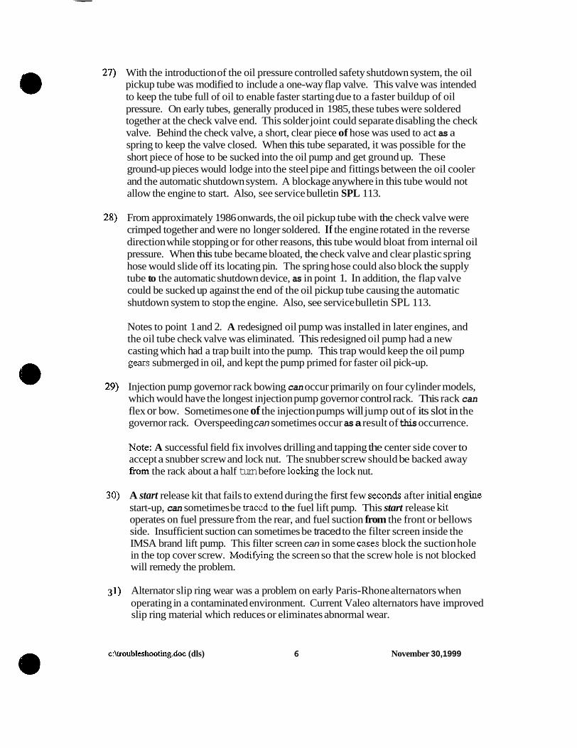
30)
3 1)
With the introduction of the oil pressure controlled safety shutdown system, the oil pickup tube was modified to include a one-way flap valve. This valve was intended to keep the tube full of oil to enable faster starting due to a faster buildup of oil pressure. On early tubes, generally produced in 1985, these tubes were soldered together at the check valve end. This solder joint could separate disabling the check valve. Behind the check valve, a short, clear piece of hose was used to act as a spring to keep the valve closed. When this tube separated, it was possible for the short piece of hose to be sucked into the oil pump and get ground up. These ground-up pieces would lodge into the steel pipe and fittings between the oil cooler and the automatic shutdown system. A blockage anywhere in this tube would not allow the engine to start. Also, see service bulletin SPL 1 13.
From approximately 1986 onwards, the oil pickup tube with the check valve were crimped together and were no longer soldered. If the engine rotated in the reverse direction while stopping or for other reasons, this tube would bloat from internal oil pressure. When this tube became bloated, the check valve and clear plastic spring hose would slide off its locating pin. The spring hose could also block the supply tube to the automatic shutdown device, as in point 1. In addition, the flap valve could be sucked up against the end of the oil pickup tube causing the automatic shutdown system to stop the engine. Also, see service bulletin SPL 113.
Notes to point 1 and 2. A redesigned oil pump was installed in later engines, and the oil tube check valve was eliminated. This redesigned oil pump had a new casting which had a trap built into the pump. This trap would keep the oil pump gears submerged in oil, and kept the pump primed for faster oil pick-up.
Injection pump governor rack bowing can occur primarily on four cylinder models, which would have the longest injection pump governor control rack. This rack can flex or bow. Sometimes one of the injection pumps will jump out of its slot in the governor rack. Overspeeding can sometimes occur as a result of this occurrence.
Note: A successful field fix involves drilling and tapping the center side cover to accept a snubber screw and lock nut. The snubber screw should be backed away from the rack about a half turn before locking the lock nut.
A start release kit that fails to extend during the first few seconds after initial engine start-up, can sometimes be traced to the fuel lift pump. This start release kit operates on fuel pressure from the rear, and fuel suction from the front or bellows side. Insufficient suction can sometimes be traced to the filter screen inside the IMSA brand lift pump. This filter screen can in some cases block the suction hole in the top cover screw. Modifling the screen so that the screw hole is not blocked will remedy the problem.
Alternator slip ring wear was a problem on early Paris-Rhone alternators when operating in a contaminated environment. Current Valeo alternators have improved slip ring material which reduces or eliminates abnormal wear.
c:\troubleshooting.doc (dls) 6 November 30,1999
32) Engines equipped with electrical shutoff. The small square cube solenoid mounted on top of the automatic protection device could sometimes malfunction. This solenoid is basically an electro-magnet which interrupts oil flow to the protection device stopping the engine. The oil supply tube brings up unfiltered oil from the oil cooler to the automatic protection device. Sometimes metal particles that are attracted to the magnet lodge the magnet piston in either the up position (run), or the down position (stop). Cleaning these parts restores proper function.
33) Key switches can become intermittent from moisture and in some cases vibration. This will cause starting problems, unwanted engine stopping, dead batteries, etc. Problems can be reduced by improved mounting methods, removing the key when not in use and shutting the protection flap. Most water enters the switch through the keyhole.
34. Governor “hunting” can be caused by the following: sticking fuel injection pump(s), bent or misaligned control rack, worn governor weight pivot bushings and/or thrust bearings, elongated hole on center governor rod, worn bushings andor pin connecting rod to spool on camshaft. See #2 and #29.
c:\troubleshooting.doc (dls) 7 November 30, 1999

DEALE WARRANTY POLICY
March 1999

HAT2 DIESEL PREMIER
LIMITED ENGINE WARRANTY
HATZ DIESEL OF AMERICA, INC., hereinafter referred to as “HATZ” warrants each new 4- cycle air-cooled diesel engine automatic low oil pressure shutoff device and sold by Hatz to be free from defects in material and workmanship, under normal use and service, for a period of twenty-four (24) months or 2,000 operating hours after the date of delivery to the original retail purchaser, or twenty-eight (28) months after the date of invoice by Hatz, whichever occurs first, and Hatz will, at their option, repair or replace at Hatz’s sales headquarters, or at a point designated by Hatz, any part or parts which shall appear to the satisfaction of Hatz upon inspection at such point, to have been defective in material or workmanship. This Warranty does not obligate Hatz to bear any transportation charges in connection with the repair or replacement of defective parts and such charges shall be borne by the original retail purchaser.
In order to obtain service under this Warranty, the original retail purchaser shall give notice in writing to Hatz within ten (10) days of the time that the defect becomes apparent. Repairs must be completed in a timely manner. Claims must be received at Hatz no later than thirty (30) days after repair date.
This Warranty shall not apply to any engine which shall have been installed or operated in a manner not recommended by Hatz; nor to any engine which shall have been repaired, altered, neglected or used in any way which, in the opinion of Hatz, adversely affects its performance; nor to any engine in which parts not authorized by Hatz have been used, which parts or the use of which have damaged, caused defects in, or otherwise adversely affected the engine or its performance; nor to any accessories installed on the engine where the accessory manufacturer has its own warranty; nor to normal maintenance services or replacement of normal service items.
Hatz reserves the right to modify, alter and improve any engine or parts without incurring any obligation to replace any engine or parts previously sold without such modified, altered or improved engine or parts.
Hatz reserves the right to require that any engine upon which warranty service is sought be made available to Hatz at Hatz’s sales headquarters or point designated by Hatz free and clear of any liens and other encumbrances.
THIS LIMITED ENGINE WARRANTY, AND THE OBLIGATION OF HATZ HEREUNDER, ARE IN LIEU OF ALL OTHER WARRANTIES, EXPRESSED, IMPLIED, OR STATUTORY, INCLUDING ANY WARRANTIES OF MERCHANTABILITY OR FITNESS FOR A PARTICULAR PURPOSE, and all other obligations or liabilities, including actual, special, direct, indirect, incidental or consequential damages, lost profits, lost sales, lost time, lost use, or contingent liabilities arising out of the failure of any engine or part to operate properly. No person is authorized to give any other warranty or to assume any additional obligation on behalf of Hatz unless made in writing and signed by an officer of Hatz. a
-1 - March 1999

HATZ DIESEL LIMITED ENGINE WARRANTY
HATZ DIESEL OF AMERICA, INC., hereinafter referred to as “HATZ, warranty each new 4- cycle air-cooled diesel engine without, automatic low oil shutoff device and sold by Hatz to be free from defects in material and workmanship, under normal use and service, for a period of twelve (12) months or 2,000 operating hours after the date of delivery to the original retail purchaser, or sixteen (16) months after the date of invoice by Hatz, whichever occurs first, and Hatz will, at their option, repair or replace at Hatz’s sales headquarters, or at a point designated by Hatz, any part or parts which shall appear to the satisfaction of Hatz upon inspection at such point, to have been defective in material or workmanship. This Warranty does not obligate Hatz to bear any transportation charges in connection with the repair or replacement of defective parts and such charges shall be borne by the original retail purchaser.
In order to obtain service under this Warranty, the original retail purchaser shall give notice in Writing to Hatz within ten (10) days of the time that the defect becomes apparent. Repairs must be completed in a timely manner. Claims must be received at Hatz no later than thirty (30) days after repair date.
This Warranty shall not apply to any engine which shall have been installed or operated in a manner not recommended by Hatz; nor to any engine which shall have been repaired, altered, neglected or used in any way which, in the opinion of Hatz, adversely affects its perforinanw, nor to any engine in which parts not authorized by Hatz have been used, which parts or the use of which have damaged, caused defects in, or otherwise adversely affected the engine or its performance; nor to any accessories installed on the engine where the accessory manufacturer has its own warranty; nor to normal maintenance services or replacement or normal service items.
Hatz reserves the right to modify, alter and improve any engine or parts without incurring any obligation to replace any engine or parts previously sold without such modified, altered or improved engine or parts. ~
Hatz reserves the right to require that any engine upon which warranty service is sought be made available to Hatz at Hatz’s sales headquarters or point designated by Hatz free and clear of any liens anil other encumbrances.
~ ..
THIS LlMITED ENGINE WARRANTY, AND THE OBLIGATION OF HATZ HEREUNDER, ARE IN LIEU OF ALL OTHER WARRANTIES EXPRESSED, IMPLIED, OR STATUTORY, INCLUDING A N Y WARRANTIES OF MERCHANTABILITY OR FITNESS FOR A PARTICULAR PURPOSE, and all other obligations or liabilities, including actual, special, direct, indirect, incidental or consequential damages, lost profits, lost sales, lost time, lost use, or contingent liabilities arising out of the failure of any engine or part to operate properly. No person is authorized to give any other warranty or to assume additional obligation on behalf of Hatz unless made in writing and signed by an officer of Hatz.
-2- March 1999

HATZ DIESEL LIMITED PARTS WARRANTY
HATZ DIESEL OF AMERICA, INC., hereinafter referred to as “HATZ”, warrants each new spare part sold by Ha@ to be free from defects in material and workmanship, under normal use and service, for a period of six (6) months after the date of delivery to the original retail purchaser, and Hatz will, at their option, repair or replace at Hatz’s sales headquarters, or at a point designated by Hatz, any part or parts which shall appear to the satisfaction of Hatz upon inspection at such point, to have been defective in material or workmanship. This Warranty does not obligate Hatz to bear any labor or transportation charges in connection with the repair or replacement of defective parts and such charges shall be borne by the original retail purchaser.
In order to obtain service under this Warranty, the original retail purchaser shall give notice in writing to Hatz within ten (10) days of the time the defect becomes apparent. Claims must be received at Hatz no later than thirty (30) days after part defect date.
This Warranty shall not apply to any parts which shall have been installed or used in a manner not recommended by Hatz; nor to any part which shall have been repaired, altered, neglected or used in any way which, in the opinion of Ha@ adversely affects its performance; nor to any part which is not a genuine Hatz part, the use of which will damage, cause defects in, or otherwise adversely affect the engine or its performance; nor to any accessories installed where the accessory manufactured has its own warranty; nor to normal maintenance services or replacement of normal service items.
Hatz reserves the right to require that any part upon which warranty service is sought be made available to Hatz at Hatz’s sales headquarters or point designated by Hatz free and clear of any liens and other encumbrances.
THIS LIMITED PARTS WARRANTY, AND THE OBLIGATION OF HATZ HEWUNDER, ARE IN LIEU OF AlLL OTHER WARRANTIES, EXPRESSED, IMPLIED, OR STATUTORY, INCLUDING ANY WARRANTIES OF MERCHANTABILITY OR OF FITNESS FOR A PARTICULAR PURPOSE, and all other obligations or liabilities, including actual, special, direct, indirect, incidental or consequential damages, lost profits, lost sales, lost time, lost use, or contingent liabilities arising out of the failure of any part to operate properly. No person is authorized to give any other warranty or to assume any additional obligation on behalf of Hatz unless made in writing and signed by an officer of Hatz.
-3- March 1999

WARRANTY EXCLUSIONS
.- The following items will not be covered in the second year under the Premier Engine Warranty:
+ Electrical components. + Hoses. + Belts. + Sealants.
+ Sealingcompounds. . + Adhesives. + Gaskets. + Clutches.
+ Hydraulic components. + Injection nozzles. + GearCases.
+ Incidental expenses: travel time, mileage, and freight.
+ Components functionally dependent on the oil circuit on engines without low oil pressure shutoff devices.
ITEMS NOT COVERED BY WARRANTY
+ Lubricants, fuels, shop towels, and supplies.
+ PhonelFadCommunication costs.
+ Deterioration caused by poor or prolonged storage of an engine such as rust, corrosion or gum and varnish caused by deteriorating fuel.
+ Anysalestaxes.
+ Diagnostic andor cleaning time.
+ Overtime labor.
+ Damage caused by the use of any starting aid or fluid.
4 March 1999