Embed Size (px)
Citation preview

ТРУБЫ, ФЛАНЦЫ, КРЕПЕЖ, ДЕТАЛИТРУБОПРОВОДА
ПО МЕЖДУНАРОДНЫМ
СТАНДАРТАМ:
ASME, DIN, NF, UNI, EN, JIS И ДР.
INMOTEH.RU
ДАННЫЙ МАТЕРИАЛ ПРЕДОСТАВЛЕН ИСКЛЮЧИТЕЛЬНО ДЛЯ ОЗНАКОМЛЕНИЯ
+7 (495) 133-39-24 INMOTEH.RU
Designation: A252 − 10
Standard Specification forWelded and Seamless Steel Pipe Piles1
This standard is issued under the fixed designation A252; the number immediately following the designation indicates the year oforiginal adoption or, in the case of revision, the year of last revision. A number in parentheses indicates the year of last reapproval. Asuperscript epsilon (´) indicates an editorial change since the last revision or reapproval.
1. Scope
1.1 This specification covers nominal (average) wall steelpipe piles of cylindrical shape and applies to pipe piles inwhich the steel cylinder acts as a permanent load-carryingmember, or as a shell to form cast-in-place concrete piles.
1.2 The values stated in inch-pound units are to be regardedas standard. The values given in parentheses are mathematicalconversions to SI units that are provided for information onlyand are not considered standard.
1.3 The text of this specification contains notes and foot-notes that provide explanatory material. Such notes andfootnotes, excluding those in tables and figures, do not containany mandatory requirements.
1.4 The following precautionary caveat pertains only to thetest method portion, Section 16 of this specification. Thisstandard does not purport to address all of the safety problems,if any, associated with its use. It is the responsibility of the userof this standard to establish appropriate safety and healthpractices and determine the applicability of regulatory limita-tions prior to use.
2. Referenced Documents
2.1 ASTM Standards:2
A370 Test Methods and Definitions for Mechanical Testingof Steel Products
A751 Test Methods, Practices, and Terminology for Chemi-cal Analysis of Steel Products
A941 Terminology Relating to Steel, Stainless Steel, RelatedAlloys, and Ferroalloys
E29 Practice for Using Significant Digits in Test Data toDetermine Conformance with Specifications
3. Terminology
3.1 Definitions:
3.1.1 Definitions of terms used in this specification shall bein accordance with Terminology A941.
3.1.2 defect—an imperfection of sufficient size or magnitudeto be cause for rejection.
3.1.3 imperfection—any discontinuity or irregularity foundin the pipe.
4. Ordering Information
4.1 Orders for material under this specification shall containinformation concerning as many of the following items as arerequired to describe the desired material adequately:
4.1.1 Quantity (feet or number of lengths),4.1.2 Name of material (steel pipe piles),4.1.3 Method of manufacture (seamless or welded),4.1.4 Grade (Tables 1 and 2),4.1.5 Size (outside diameter and nominal wall thickness),4.1.6 Lengths (single random, double random, or uniform)
(see Section 13),4.1.7 End finish (Section 15), and4.1.8 ASTM specification designation and year of issue,4.1.9 Location of purchaser’s inspection (see 19.1), and4.1.10 Bar coding (see 22.2).
5. Materials and Manufacture
5.1 The piles shall be made by the seamless, electricresistance welded, flash welded, or fusion welded process. Theseams of welded pipe piles shall be longitudinal, helical-butt,or helical-lap.
NOTE 1—For welded pipe piles, the weld should not fail when theproduct is properly fabricated and installed and subjected to its intendedend use.
6. Process
6.1 The steel shall be made by one or more of the followingprocesses: open-hearth, basic-oxygen, or electric-furnace.
7. Chemical Composition
7.1 The steel shall contain no more than 0.050 % phospho-rous.
8. Heat Analysis
8.1 Each heat analysis shall conform to the requirementspecified in 7.1. When requested by the purchaser, the appli-cable heat analyses shall be reported to the purchaser ro thepurchaser’s representative.
1 This specification is under the jurisdiction of ASTM Committee A01 on Steel,Stainless Steel and Related Alloys and is the direct responsibility of SubcommitteeA01.09 on Carbon Steel Tubular Products.
Current edition approved Oct. 1, 2010. Published November 2010. Originallyapproved in 1944. Last previous edition approved in 2007 as A252 – 98(2007).DOI: 10.1520/A0252-10.
2 For referenced ASTM standards, visit the ASTM website, www.astm.org, orcontact ASTM Customer Service at [email protected]. For Annual Book of ASTMStandards volume information, refer to the standard’s Document Summary page onthe ASTM website.
Copyright © ASTM International, 100 Barr Harbor Drive, PO Box C700, West Conshohocken, PA 19428-2959. United States
1Copyright by ASTM Int'l (all rights reserved);
9. Product Analysis
9.1 Chemical analysis shall be in accordance with TestMethods, Practices, and Terminology A751.
9.2 It shall be permissible for the purchaser to make productanalyses using samples from lots of pipe piles as follows:
Pipe Size OutsideDiameter, in. (mm)
Number of Samples and Size of Lot
Under 14 (355.6) 2 from 200 pipe or fraction thereof14 to 36, incl (355.6
to 914)2 from 100 pipe or fraction thereof
Over 36 (914) 2 from 3000 ft (914 m) or fraction thereof
The product analyses shall conform to the requirement in7.1.
9.3 If the chemical compositions of both of the samplesrepresenting a lot fail to conform to the specified requirement,the lot shall be rejected or analyses of four additional samplesselected from the lot shall be made, and each shall conform tothe specified requirement. If the chemical composition of onlyone of the samples representing a lot fails to conform to thespecified requirement, the lot shall be rejected or analyses oftwo additional samples selected from the lot shall be made, andeach shall conform to the specified requirement.
10. Tensile Requirements
10.1 The material shall conform to the requirements as totensile properties prescribed in Tables 1 and 2.
10.2 The yield point shall be determined by the drop of thebeam, by the halt in the gage of the testing machine, by the useof dividers, or by other approved methods. When a definiteyield point is not exhibited, the yield strength corresponding toa permanent offset of 0.2 % of the gage length of the specimen,or to a total extension of 0.5 % of the gage length under loadshall be determined.
11. Weights Per Unit Length
11.1 The weights per unit length for various sizes of pipepiles are listed in Table 3.
11.2 For pipe pile sizes not listed in Table 3, the weight perunit length shall be calculated as follows:
W 5 10.69~D 2 t!t (1)
where:W = weight per unit length, lb/ft,
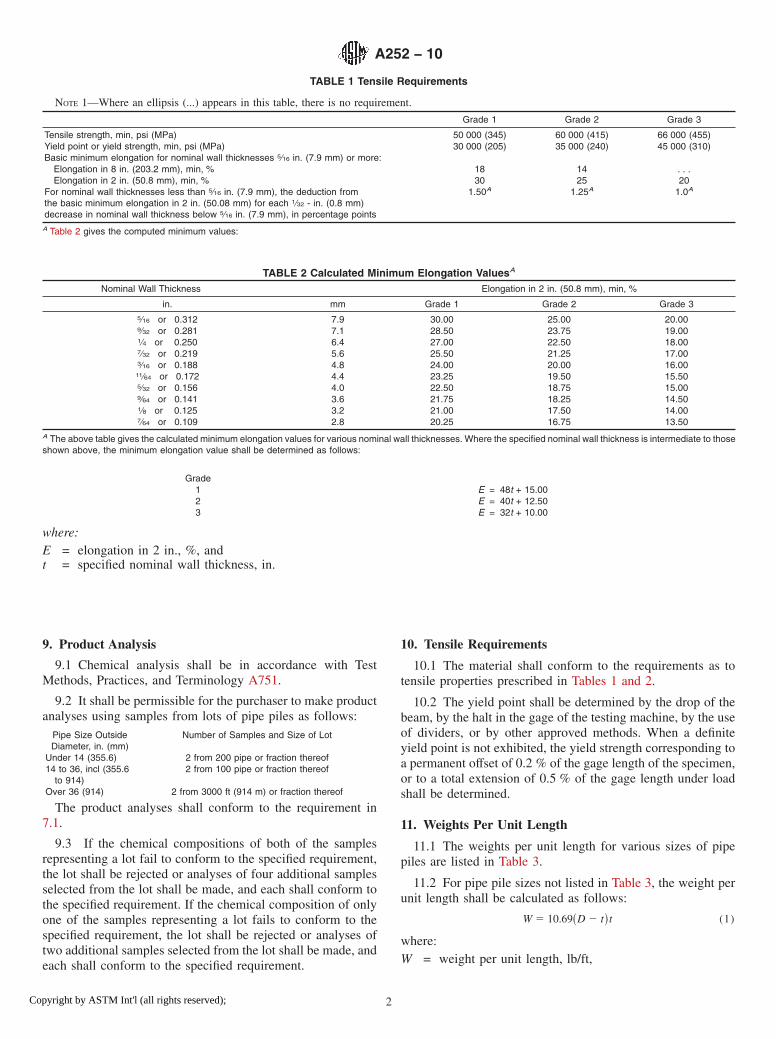
TABLE 1 Tensile Requirements
NOTE 1—Where an ellipsis (...) appears in this table, there is no requirement.
Grade 1 Grade 2 Grade 3
Tensile strength, min, psi (MPa) 50 000 (345) 60 000 (415) 66 000 (455)Yield point or yield strength, min, psi (MPa) 30 000 (205) 35 000 (240) 45 000 (310)Basic minimum elongation for nominal wall thicknesses 5⁄16 in. (7.9 mm) or more:
Elongation in 8 in. (203.2 mm), min, % 18 14 . . .Elongation in 2 in. (50.8 mm), min, % 30 25 20
For nominal wall thicknesses less than 5⁄16 in. (7.9 mm), the deduction fromthe basic minimum elongation in 2 in. (50.08 mm) for each 1⁄32 - in. (0.8 mm)decrease in nominal wall thickness below 5⁄16 in. (7.9 mm), in percentage points
1.50A 1.25A 1.0A
A Table 2 gives the computed minimum values:
TABLE 2 Calculated Minimum Elongation ValuesA
Nominal Wall Thickness Elongation in 2 in. (50.8 mm), min, %
in. mm Grade 1 Grade 2 Grade 35⁄16 or 0.312 7.9 30.00 25.00 20.009⁄32 or 0.281 7.1 28.50 23.75 19.001⁄4 or 0.250 6.4 27.00 22.50 18.007⁄32 or 0.219 5.6 25.50 21.25 17.003⁄16 or 0.188 4.8 24.00 20.00 16.0011⁄64 or 0.172 4.4 23.25 19.50 15.505⁄32 or 0.156 4.0 22.50 18.75 15.009⁄64 or 0.141 3.6 21.75 18.25 14.501⁄8 or 0.125 3.2 21.00 17.50 14.007⁄64 or 0.109 2.8 20.25 16.75 13.50
A The above table gives the calculated minimum elongation values for various nominal wall thicknesses. Where the specified nominal wall thickness is intermediate to thoseshown above, the minimum elongation value shall be determined as follows:
Grade1 E = 48t + 15.002 E = 40t + 12.503 E = 32t + 10.00
where:E = elongation in 2 in., %, andt = specified nominal wall thickness, in.
A252 − 10
2Copyright by ASTM Int'l (all rights reserved);
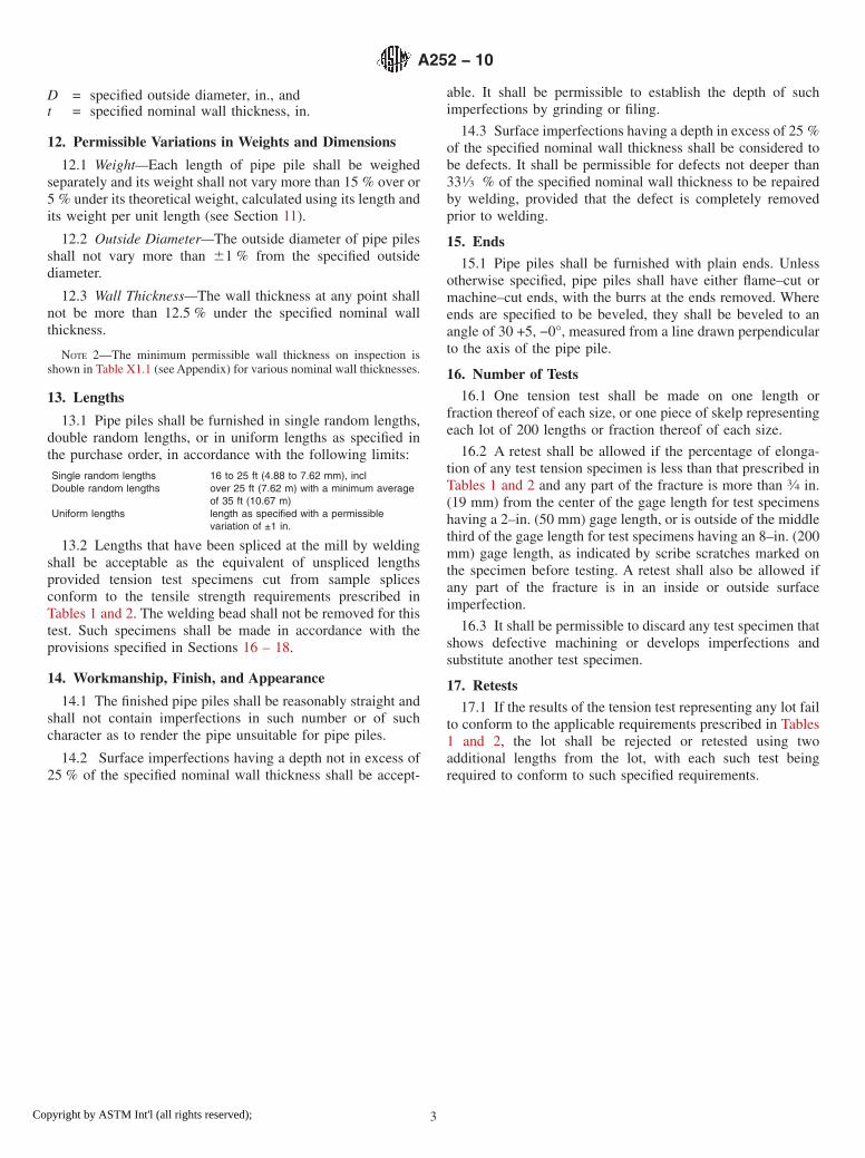
D = specified outside diameter, in., andt = specified nominal wall thickness, in.
12. Permissible Variations in Weights and Dimensions
12.1 Weight—Each length of pipe pile shall be weighedseparately and its weight shall not vary more than 15 % over or5 % under its theoretical weight, calculated using its length andits weight per unit length (see Section 11).
12.2 Outside Diameter—The outside diameter of pipe pilesshall not vary more than 61 % from the specified outsidediameter.
12.3 Wall Thickness—The wall thickness at any point shallnot be more than 12.5 % under the specified nominal wallthickness.
NOTE 2—The minimum permissible wall thickness on inspection isshown in Table X1.1 (see Appendix) for various nominal wall thicknesses.
13. Lengths
13.1 Pipe piles shall be furnished in single random lengths,double random lengths, or in uniform lengths as specified inthe purchase order, in accordance with the following limits:Single random lengths 16 to 25 ft (4.88 to 7.62 mm), inclDouble random lengths over 25 ft (7.62 m) with a minimum average
of 35 ft (10.67 m)Uniform lengths length as specified with a permissible
variation of ±1 in.
13.2 Lengths that have been spliced at the mill by weldingshall be acceptable as the equivalent of unspliced lengthsprovided tension test specimens cut from sample splicesconform to the tensile strength requirements prescribed inTables 1 and 2. The welding bead shall not be removed for thistest. Such specimens shall be made in accordance with theprovisions specified in Sections 16 – 18.
14. Workmanship, Finish, and Appearance
14.1 The finished pipe piles shall be reasonably straight andshall not contain imperfections in such number or of suchcharacter as to render the pipe unsuitable for pipe piles.
14.2 Surface imperfections having a depth not in excess of25 % of the specified nominal wall thickness shall be accept-
able. It shall be permissible to establish the depth of suchimperfections by grinding or filing.
14.3 Surface imperfections having a depth in excess of 25 %of the specified nominal wall thickness shall be considered tobe defects. It shall be permissible for defects not deeper than331⁄3 % of the specified nominal wall thickness to be repairedby welding, provided that the defect is completely removedprior to welding.
15. Ends
15.1 Pipe piles shall be furnished with plain ends. Unlessotherwise specified, pipe piles shall have either flame–cut ormachine–cut ends, with the burrs at the ends removed. Whereends are specified to be beveled, they shall be beveled to anangle of 30 +5, −0°, measured from a line drawn perpendicularto the axis of the pipe pile.
16. Number of Tests
16.1 One tension test shall be made on one length orfraction thereof of each size, or one piece of skelp representingeach lot of 200 lengths or fraction thereof of each size.
16.2 A retest shall be allowed if the percentage of elonga-tion of any test tension specimen is less than that prescribed inTables 1 and 2 and any part of the fracture is more than 3⁄4 in.(19 mm) from the center of the gage length for test specimenshaving a 2–in. (50 mm) gage length, or is outside of the middlethird of the gage length for test specimens having an 8–in. (200mm) gage length, as indicated by scribe scratches marked onthe specimen before testing. A retest shall also be allowed ifany part of the fracture is in an inside or outside surfaceimperfection.
16.3 It shall be permissible to discard any test specimen thatshows defective machining or develops imperfections andsubstitute another test specimen.
17. Retests
17.1 If the results of the tension test representing any lot failto conform to the applicable requirements prescribed in Tables1 and 2, the lot shall be rejected or retested using twoadditional lengths from the lot, with each such test beingrequired to conform to such specified requirements.
A252 − 10
3Copyright by ASTM Int'l (all rights reserved);
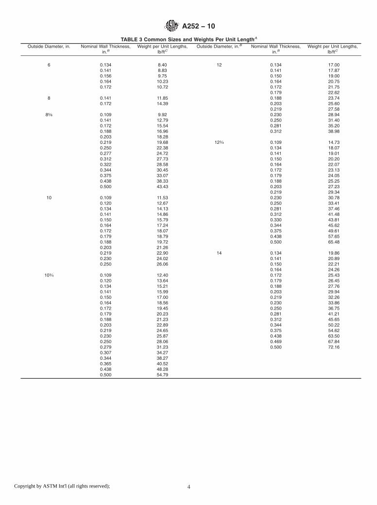
TABLE 3 Common Sizes and Weights Per Unit LengthA
Outside Diameter, in. Nominal Wall Thickness,in.B
Weight per Unit Lengths,lb/ftC
Outside Diameter, in.B Nominal Wall Thickness,in.B
Weight per Unit Lengths,lb/ftC
6 0.134 8.40 12 0.134 17.000.141 8.83 0.141 17.870.156 9.75 0.150 19.000.164 10.23 0.164 20.750.172 10.72 0.172 21.75
0.179 22.628 0.141 11.85 0.188 23.74
0.172 14.39 0.203 25.600.219 27.58
85⁄8 0.109 9.92 0.230 28.940.141 12.79 0.250 31.400.172 15.54 0.281 35.200.188 16.96 0.312 38.980.203 18.280.219 19.68 123⁄4 0.109 14.730.250 22.38 0.134 18.070.277 24.72 0.141 19.010.312 27.73 0.150 20.200.322 28.58 0.164 22.070.344 30.45 0.172 23.130.375 33.07 0.179 24.050.438 38.33 0.188 25.250.500 43.43 0.203 27.23
0.219 29.3410 0.109 11.53 0.230 30.78
0.120 12.67 0.250 33.410.134 14.13 0.281 37.460.141 14.86 0.312 41.480.150 15.79 0.330 43.810.164 17.24 0.344 45.620.172 18.07 0.375 49.610.179 18.79 0.438 57.650.188 19.72 0.500 65.480.203 21.260.219 22.90 14 0.134 19.860.230 24.02 0.141 20.890.250 26.06 0.150 22.21
0.164 24.26103⁄4 0.109 12.40 0.172 25.43
0.120 13.64 0.179 26.450.134 15.21 0.188 27.760.141 15.99 0.203 29.940.150 17.00 0.219 32.260.164 18.56 0.230 33.860.172 19.45 0.250 36.750.179 20.23 0.281 41.210.188 21.23 0.312 45.650.203 22.89 0.344 50.220.219 24.65 0.375 54.620.230 25.87 0.438 63.500.250 28.06 0.469 67.840.279 31.23 0.500 72.160.307 34.270.344 38.270.365 40.520.438 48.280.500 54.79
A252 − 10
4Copyright by ASTM Int'l (all rights reserved);

TABLE 3 Continued
Outside Diameter, in. Nominal Wall Thickness,in.B
Weight per Unit Lengths,lb/ftC
Outside Diameter, in.B Nominal Wall Thickness,in.B
Weight per Unit Lengths,lb/ftC
16 0.134 22.73 20 0.141 29.930.141 23.90 0.172 36.460.150 25.42 0.188 39.820.164 27.76 0.219 46.310.172 29.10 0.250 52.780.179 30.27 0.281 59.230.188 31.78 0.312 65.660.203 34.28 0.344 72.280.219 36.95 0.375 78.670.230 38.77 0.438 91.590.250 42.09 0.469 97.920.281 47.22 0.500 104.230.312 52.320.344 57.57 22 0.172 40.130.375 62.64 0.188 43.840.438 72.86 0.219 50.990.469 77.87 0.250 58.130.500 82.85 0.281 65.24
0.312 72.3418 0.141 26.92 0.375 86.69
0.172 32.78 0.438 100.960.188 35.80 0.469 107.950.219 41.63 0.500 114.920.230 43.690.250 47.44 24 0.172 43.810.281 53.23 0.188 47.860.312 58.99 0.219 55.670.344 64.93 0.250 63.470.375 70.65 0.281 71.250.438 82.23 0.312 79.010.469 87.89 0.375 94.710.500 93.54 0.438 110.32
0.469 117.980.500 125.62
A Subject to agreement between the manufacturer and the purchaser, sizes and weights per unit length other than those listed shall be permitted.B 1 in. = 25.4 mmC 1 lb/ft = 1.49 kg/m.
18. Test Specimens and Test Methods
18.1 The tension test specimens and test methods shall be inaccordance with Test Methods and Definitions A370, espe-cially Annex A2.
18.2 At the option of the manufacturer, the tension testspecimens shall be longitudinal or transverse strip testspecimens, with a gage length of 2 in. (50 mm) or 8 in. (200mm), taken from the pipe or the skelp. Within their gagelength, longitudinal strip test specimens shall be nominally 11⁄2in. (38 mm) wide, non-flattened, and with parallel sides.
18.3 For welded pipe piles, the tension test specimens shallbe taken as follows:
18.3.1 For longitudinal–seam pipe piles, any longitudinalstrip test specimens shall be taken from the pipe parallel to thepipe axis and 90° from the weld, or from the skelp at acorresponding location and orientation, and any transversestrip test specimens shall be taken from the pipe 90° to the pipeaxis and 180° from the weld, or from the skelp at a correspond-ing location and orientation.
18.3.2 For helical-seam pipe piles, any longitudinal striptest specimens shall be taken from the pipe parallel to the pipeaxis and at such a location that the center of the specimen islocated at least a quarter of the distance between adjacent weldconvolutions, or from the skelp at a corresponding location andorientation; and transverse specimens shall be taken from the
pipe 90° to the pipe axis and at such a location that the centerof the specimen is located approximately half the distancebetween adjacent weld convolutions, or from the skelp at acorresponding location and orientation.
18.4 Specimens shall be tested at room temperature.
19. Inspection
19.1 The inspector representing the purchaser shall haveentry, at all times while work on the contract of the purchaseris being performed, to all parts of the manufacturer’s worksthat concern the manufacture of the material ordered. Themanufacturer shall afford the inspector all reasonable facilitiesto satisfy the inspector that the material is being furnished inaccordance with the requirements of this specification and anyother requirements specified in the purchase order. All tests andinspections shall be made at the place of manufacture prior toshipment, unless otherwise specified in the purchase order, andshall be so conducted as not to interfere unnecessarily with theoperation of the works.
20. Rejection
20.1 It shall be permissible for the purchaser inspect thepipe piles received from the manufacturer and reject any pipepile that does not meet the requirements of this specificationand the purchase order, based upon the applicable inspectionand test methods. The purchaser shall notify the manufacturer
A252 − 10
5Copyright by ASTM Int'l (all rights reserved);
of any pipe pile that has been rejected, and the disposition ofsuch pipe piles shall be subject to agreement between themanufacturer and the purchaser.
20.2 It shall be permissible for the purchaser to set aside anypipe pile that is found in fabrication or installation within thescope of this specification to be unsuitable for the intended enduse, based on the requirements of this specification. Thepurchaser shall notify the manufacturer of any pipe pile thathas been set aside. Such pipe piles shall be subject to mutualinvestigation as to the nature and severity of the deficiency andthe forming or installation, or both, conditions involved. Thedisposition of such pipe piles shall be subject to agreementbetween the manufacturer and the purchaser.
21. Certification
21.1 Where specified in the purchase order, the manufac-turer shall furnish a certificate of compliance stating that thepipe pile was manufactured, tested, and inspected in accor-dance with the requirements of this specification (includingyear date) and any requirements specified in the purchaseorder, and was found to meet such requirements, and shall
furnish a test report containing the results of the applicable heatanalyses, product analyses, and tension tests.
22. Product Marking
22.1 Each length of pipe pile shall be legibly marked bystenciling, stamping, or rolling to show: the name or brand ofthe manufacturer; the heat number; the process of manufacture(seamless, flash welded, fusion welded, or electric resistancewelded), the type of helical seam (helical-lap or helical-butt), ifapplicable; the outside diameter, nominal wall thickness,length, and weight per unit length; the specification designation(year date not required); and the grade.
22.2 Bar Coding—In addition to the requirements in 22.1, itshall be permissible for bar coding to be used as a supplemen-tary identification method; when a specific bar coding systemis specified in the purchase order, that system shall be used.
23. Keywords
23.1 seamless steel pipe; steel piles; steel pipe; welded steelpipe
APPENDIX
(Nonmandatory Information)
X1. Minimum Permissible Pipe Wall Thicknesses on Inspection
X1.1 See Table X1.1 for minimum wall thicknesses.
A252 − 10
6Copyright by ASTM Int'l (all rights reserved);
ASTM International takes no position respecting the validity of any patent rights asserted in connection with any item mentionedin this standard. Users of this standard are expressly advised that determination of the validity of any such patent rights, and the riskof infringement of such rights, are entirely their own responsibility.
This standard is subject to revision at any time by the responsible technical committee and must be reviewed every five years andif not revised, either reapproved or withdrawn. Your comments are invited either for revision of this standard or for additional standardsand should be addressed to ASTM International Headquarters. Your comments will receive careful consideration at a meeting of theresponsible technical committee, which you may attend. If you feel that your comments have not received a fair hearing you shouldmake your views known to the ASTM Committee on Standards, at the address shown below.
This standard is copyrighted by ASTM International, 100 Barr Harbor Drive, PO Box C700, West Conshohocken, PA 19428-2959,United States. Individual reprints (single or multiple copies) of this standard may be obtained by contacting ASTM at the aboveaddress or at 610-832-9585 (phone), 610-832-9555 (fax), or [email protected] (e-mail); or through the ASTM website(www.astm.org). Permission rights to photocopy the standard may also be secured from the ASTM website (www.astm.org/COPYRIGHT/).
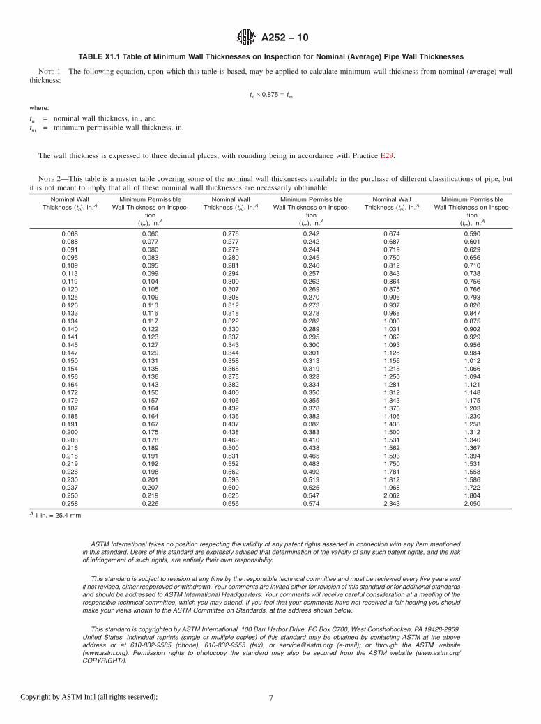
TABLE X1.1 Table of Minimum Wall Thicknesses on Inspection for Nominal (Average) Pipe Wall Thicknesses
NOTE 1—The following equation, upon which this table is based, may be applied to calculate minimum wall thickness from nominal (average) wallthickness:
tn 3 0.875 5 tm
where:
tn = nominal wall thickness, in., andtm = minimum permissible wall thickness, in.
The wall thickness is expressed to three decimal places, with rounding being in accordance with Practice E29.
NOTE 2—This table is a master table covering some of the nominal wall thicknesses available in the purchase of different classifications of pipe, butit is not meant to imply that all of these nominal wall thicknesses are necessarily obtainable.
Nominal WallThickness (tn), in.A
Minimum PermissibleWall Thickness on Inspec-
tion(tm), in.A
Nominal WallThickness (tn), in.A
Minimum PermissibleWall Thickness on Inspec-
tion(tm), in.A
Nominal WallThickness (tn), in.A
Minimum PermissibleWall Thickness on Inspec-
tion(tm), in.A
0.068 0.060 0.276 0.242 0.674 0.5900.088 0.077 0.277 0.242 0.687 0.6010.091 0.080 0.279 0.244 0.719 0.6290.095 0.083 0.280 0.245 0.750 0.6560.109 0.095 0.281 0.246 0.812 0.7100.113 0.099 0.294 0.257 0.843 0.7380.119 0.104 0.300 0.262 0.864 0.7560.120 0.105 0.307 0.269 0.875 0.7660.125 0.109 0.308 0.270 0.906 0.7930.126 0.110 0.312 0.273 0.937 0.8200.133 0.116 0.318 0.278 0.968 0.8470.134 0.117 0.322 0.282 1.000 0.8750.140 0.122 0.330 0.289 1.031 0.9020.141 0.123 0.337 0.295 1.062 0.9290.145 0.127 0.343 0.300 1.093 0.9560.147 0.129 0.344 0.301 1.125 0.9840.150 0.131 0.358 0.313 1.156 1.0120.154 0.135 0.365 0.319 1.218 1.0660.156 0.136 0.375 0.328 1.250 1.0940.164 0.143 0.382 0.334 1.281 1.1210.172 0.150 0.400 0.350 1.312 1.1480.179 0.157 0.406 0.355 1.343 1.1750.187 0.164 0.432 0.378 1.375 1.2030.188 0.164 0.436 0.382 1.406 1.2300.191 0.167 0.437 0.382 1.438 1.2580.200 0.175 0.438 0.383 1.500 1.3120.203 0.178 0.469 0.410 1.531 1.3400.216 0.189 0.500 0.438 1.562 1.3670.218 0.191 0.531 0.465 1.593 1.3940.219 0.192 0.552 0.483 1.750 1.5310.226 0.198 0.562 0.492 1.781 1.5580.230 0.201 0.593 0.519 1.812 1.5860.237 0.207 0.600 0.525 1.968 1.7220.250 0.219 0.625 0.547 2.062 1.8040.258 0.226 0.656 0.574 2.343 2.050
A 1 in. = 25.4 mm
A252 − 10
7Copyright by ASTM Int'l (all rights reserved);