Embed Size (px)
Citation preview

SPECIFICATION (Reference sheet)
· Supplier : Samsung electro-mechanics · Samsung P/N: CL05A105KP5NNNC
· Product : Multi-layer Ceramic Capacitor · Description : CAP, 1uF, 10V, ±10%, X5R, 0402
CL 05 A 105 K P 5 N N N C① ② ③ ④ ⑤ ⑥ ⑦ ⑧ ⑨ ⑩ ⑪
①①①① Series Samsung Multi-layer Ceramic Capacitor
②②②② Size 0402 (inch code) L: 1.00 ± 0.05 ㎜ W: 0.50 ± 0.05 ㎜
③③③③ Dielectric X5R ⑧ Inner electrode
④④④④ Capacitance 1 Termination
⑤⑤⑤⑤ Capacitance ±10 % Plating (Pb Free)
tolerance ⑨⑨⑨⑨ Product Normal
⑥⑥⑥⑥ Rated Voltage 10 V ⑩⑩⑩⑩ Special Reserved for future use
⑦⑦⑦⑦ Thickness 0.50 ± 0.05 ㎜ ⑪⑪⑪⑪ Packaging Cardboard Type, 7" reel
B. Structure & Dimension
CL05A105KP5NNNC 1.00 ± 0.05 0.50 ± 0.05 0.50 ± 0.05 0.25 ± 0.10
A. Samsung Part Number
Ni
uF
Sn 100%
Samsung P/NDimension(㎜)
WL T BW
Cu
1

C. Samsung Reliablility Test and Judgement Condition
Capacitance Within specified tolerance
Tan δ (DF) 0.1 max.
Insulation 10,000Mohm or 100Mohm×㎌ Rated Voltage 60~120 sec.
Resistance Whichever is smaller
Appearance No abnormal exterior appearance Microscope (×10)
Withstanding No dielectric breakdown or of the rated voltage
Voltage mechanical breakdown
Temperature X5RCharacteristics (From-55℃ to 85℃, Capacitance change should be within ±15%)
Adhesive Strength No peeling shall be occur on the 500g·f, for 10±1 sec.
of Termination terminal electrodeBending Strength Capacitance change : within ±12.5% Bending to the limit (1㎜)
with 1.0mm/sec.
Solderability More than 75% of terminal surface SnAg3.0Cu0.5 solderis to be soldered newly 245±5℃, 3±0.3sec.
(preheating : 80~120℃ for 10~30sec.)
Resistance to Capacitance change : within ±7.5% Solder pot : 270±5℃, 10±1sec.
Soldering Heat Tan δ, IR : initial spec.Vibration Test Capacitance change : within ± 5% Amplitude : 1.5mm
Tan δ, IR : initial spec. From 10㎐ to 55㎐ (return : 1min.)2hours × 3 direction (x, y, z)
Moisture Capacitance change : within ±12.5% With rated voltageResistance Tan δ : 0.2 max 40±2℃, 90~95%RH, 500+12/-0hrs
IR : 500Mohm or 12.5Mohm × ㎌
Whichever is smaller
High Temperature Capacitance change : within ±12.5% With of the rated voltage
Resistance Tan δ : 0.2 max Max. operating temperature
IR : 1,000Mohm or 25Mohm × ㎌ 1000+48/-0hrsWhichever is smaller
Temperature Capacitance change : within ±7.5% 1 cycle conditionCycling Tan δ, IR : initial spec. Min. operating temperature → 25℃
→ Max. operating temperature → 25℃
5 cycle test※ The reliability test condition can be replaced by the corresponding accelerated test condition.
D. Recommended Soldering method :Reflow ( Reflow Peak Temperature : 260+0/-5℃, 10sec. Max )
Product specifications included in the specifications are effective as of March 1, 2013. Please be advised that they are standard product specifications for reference only.We may change, modify or discontinue the product specifications without notice at any time. So, you need to approve the product specifications before placing an order.Should you have any question regarding the product specifications,please contact our sales personnel or application engineers.
250%
150%
Judgement Test condition
1㎑ ±10% / 1.0±0.2Vrms
*A capacitor prior to measuring the capacitance is heattreated at 150℃+0/-10℃ for 1 hour and maintained inambient air for 24±2 hours.
2

MLCC Pro
E. Recomm
(Subs
☞ Materia
☞
☞ Caution
oduct Ma
mended TE
strate for be
Siz
al : Glass ep
: Copper f
: Abnormali
nual
EST PCB
Size cod
02
03
05
10
21
31
32
43
55
ending stren
ze code
02
03
05
10
21
31
32
43
55
oxy substrat
foil (T=0.035
ity can occu
( Adhesive
de Siz
0.
0.
1.0
1.
2.0
3.
3.
4.
5.
gth test)
Size (mm)
0.4 × 0.2
0.6 × 0.3
1.0 × 0.5
1.6 × 0.8
2.0 × 1.25
3.2 × 1.6
3.2 × 2.5
4.5 × 3.2
5.7 × 5.0
te ☞ T
5 ㎜) ☞
r if lead-bas
strength of
ze (mm)
.4 × 0.2
.6 × 0.3
0. × 0.5
.6 × 0.8
0 × 1.25
.2 × 1.6
.2 × 2.5
.5 × 3.2
.7 × 5.0
a
0.2
0.3
0.4
1.0
1.2
2.2
2.2
3.5
4.5
Thickness : T
: So
sed solder (K
d
b
termination)
a b
0.20 0.1
0.30 0.3
0.40 0.5
1.00 1.0
1.20 1.4
2.20 1.4
2.20 1.4
3.50 1.7
4.50 1.7
(Su
b c
0.6 0.2
0.9 0.3
1.5 0.5
3.0 1.2
4.0 1.6
5.0 2.0
5.0 2.9
7.0 3.7
8.0 5.6
T=1.6 ㎜ (T=
older resist
KSD 6704) w
)
b c
17 0.26
30 0.30
55 0.50
00 1.20
40 1.65
40 2.00
40 2.90
75 3.70
75 5.60
ubstrate for R
d
2 5.0
3 5.0
5 5.0
2 5.0
65 5.0
0 5.0
9 5.0
7 5.0
6 5.0
0.8 ㎜ for 0
with 3% silver
Reliability te
e
5.5
5.5
5.5
5.5
5.5
5.5
5.5
5.5
5.5
03/05)
r is used.
est)
e
a
c
3
MLCC Pro
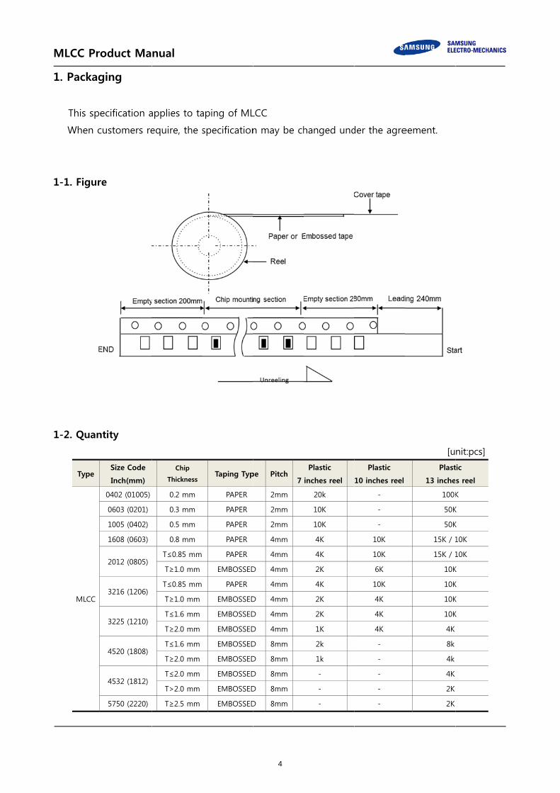
1. Packag
This spe
When c
1-1. Figur
1-2. Quan
Type
MLCC
oduct Ma
ging
ecification a
customers re
e
ntity
Size Code
Inch(mm)
0402 (01005)
0603 (0201)
1005 (0402)
1608 (0603)
2012 (0805)
3216 (1206)
3225 (1210)
4520 (1808)
4532 (1812)
5750 (2220)
nual
applies to ta
equire, the s
Chip
Thickness
0.2 mm
0.3 mm
0.5 mm
0.8 mm
T≤0.85 mm
T≥1.0 mm
T≤0.85 mm
T≥1.0 mm
T≤1.6 mm
T≥2.0 mm
T≤1.6 mm
T≥2.0 mm
T≤2.0 mm
T>2.0 mm
T≥2.5 mm
aping of ML
specification
Taping Typ
PAPER
PAPER
PAPER
PAPER
PAPER
EMBOSSED
PAPER
EMBOSSED
EMBOSSED
EMBOSSED
EMBOSSED
EMBOSSED
EMBOSSED
EMBOSSED
EMBOSSED
LCC
n may be ch
pe Pitch7
2mm
2mm
2mm
4mm
4mm
D 4mm
4mm
D 4mm
D 4mm
D 4mm
D 8mm
D 8mm
D 8mm
D 8mm
D 8mm
hanged und
Plastic
inches reel
20k
10K
10K
4K
4K
2K
4K
2K
2K
1K
2k
1k
-
-
-
der the agre
Plastic
10 inches reel
-
-
-
10K
10K
6K
10K
4K
4K
4K
-
-
-
-
-
eement.
[u
Plast
13 inche
100K
50K
50K
15K / 1
15K / 1
10K
10K
10K
10K
4K
8k
4k
4K
2K
2K
nit:pcs] tic
s reel
K
K
K
10K
10K
K
K
K
K
4

MLCC Product Manual
1-3. Tape Size
1-3-1. Cardboard(Paper) tape : 4mm pitch
[unit:mm] Size
Inch(mm) A B W F E P1 P2 P0 D t
0603 (1608)
1.00 ±0.10
1.90 ±0.10
8.00 ±0.30
3.50±0.05
1.75±0.10
4.00±0.10
2.00±0.05
4.00±0.10
φ1.50 +0.10/-0
1.1 Below
0805 (2012)
1.55 ±0.10
2.30 ±0.10
1206 (3216)
2.05 ±0.10
3.60 ±0.10
※ The A, B in the table above are based on normal dimensions. The data may be changed
with the special size tolerances.
1-3-2. Cardboard(Paper) tape : 2mm pitch
[unit:mm]
Size Inch(mm)
A B W F E P1 P2 P0 D t
01005 (0402)
0.25 ±0.02
0.46 ±0.02
8.00 ±0.30
3.50 ±0.05
1.75 ±0.10
2.00 ±0.05
2.00 ±0.05
4.00 ±0.10
φ1.50 +0.10/-0.03
0.25 ±0.02
0201 (0603)
0.38 ±0.03
0.68 ±0.03
0.35 ±0.03
0402 (1005)
0.62 ±0.05
1.12 ±0.05
0.60 ±0.05
0204 (0510)
0.62 +0.05/-0.10
1.12 +0.05/-0.10
0.37 ±0.03
※ The A, B in the table above are based on normal dimensions. The data may be changed
with the special size tolerances.
5

MLCC Product Manual
1-3-3. Embossed(Plastic) tape
[unit:mm]
Size
Inch(mm) A B W F E P1 P2 P0 D t1 t0
01005
(0402)
0.23
±0.02
0.45
±0.02
4.00
±0.05
1.80
±0.02
0.90
±0.05
1.00
±0.02
1.00
±0.02
2.00
±0.03
φ0.80
±0.04 0.35
Below
0.50
Below 015008
(05025)
0.32
±0.03
0.58
±0.03
8.00
±0.30
3.50
±0.05
1.75
±0.10
2.00
±0.05
2.00
±0.05
4.00
±0.10
φ1.50
+0.10
/-0.03
0603
(1608)
1.05
±0.15
1.90
±0.15
4.00
±0.10
φ1.50
+0.10
/-0
2.50
Below
0.60
Below
0805
(2012)
1.45
±0.20
2.30
±0.20
1206
(3216)
1.90
±0.20
3.50
±0.20
1210
(3225)
2.80
±0.20
3.60
±0.20
1808
(4520)
2.30
±0.20
4.90
±0.20
12.0
±0.30
5.60
±0.05
8.00
±0.10
3.80
Below
1812
(4532)
3.60
±0.20
4.90
±0.20
2220
(5750)
5.50
±0.20
6.20
±0.20
0204
(0510)
0.62
+0.05
/-0.10
1.12
+0.05
/-0.108.00
±0.30
3.50
±0.05
4.00
±0.10
2.50
Below 0306
(0816)
1.10
±0.20
1.90
±0.20
※ The A, B in the table above are based on normal dimensions. The data may be changed
with the special size tolerances.
6

MLCC Pro
1-3-4. Reel
Symbol
7”Reel
10”Reel
13”Reel
1-4. Cover
1-4-1. Peel-
10 g
1-4-2. Meas
-Tap
(IE
* If t
oduct Ma
Size
Tape Widt
4mm
8mm
12mm
8mm
8mm
12mm
r tape pee
-off force
.f ≤ peel-of
surement M
ping Packag
C 60286-3 P
he static ele
nual
th A
φ178±2.
φ178±2.
φ178±2.
φ258±2.
φ330±2.
φ330±2.
l-off force
ff force ≤ 70
ethod
ing design :
Packaging of
ectricity of SM
B
0 MINφ50
0 MINφ50
0 MINφ50
0 MINφ70
0 MINφ70
0 MINφ70
0 g.f
Packaging
f componen
MT process
C
φ13±0.5
φ13±0.5
φ13±0.5
φ13±0.5
φ13±0.5
φ13±0.5
design follo
ts for autom
causes any
D
21±0.8
21±0.8
21±0.8
21±0.8
21±0.8
21±0.8
ws IEC 6028
matic handlin
problems, p
E
2.0±0.5
2.0±0.5
2.0±0.5
2.0±0.5
2.0±0.5
2.0±0.5
86-3 standard
ng - parts 3)
lease contac
W
5±0.5
10±1.5
13±0.5
10±1.5
10±1.5
13±0.5
d.
ct us.
[unit:mm]
t
1.2±0.2
0.9±0.2
1.2±0.2
1.8±0.2
1.8±0.2
2.2±0.2
7
MLCC Pro
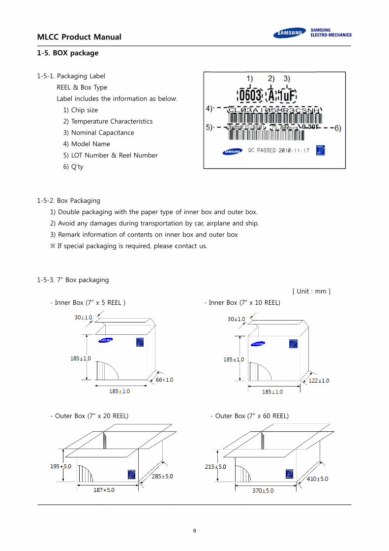
1-5. BOX
1-5-1. Pack
REEL
Labe
1)
2)
3)
4)
5)
6)
1-5-2. Box
1) Dou
2) Avoi
3) Rem
※ If sp
1-5-3. 7" Bo
- Inner
- Outer
oduct Ma
package
kaging Label
L & Box Type
el includes th
Chip size
Temperature
Nominal Ca
Model Nam
LOT Numbe
Q’ty
Packaging
ble packagin
id any dama
mark informat
pecial packag
ox packaging
r Box (7" x 5
r Box (7" x 2
nual
e
he informatio
e Characteris
apacitance
me
er & Reel Nu
ng with the
ages during
tion of cont
ging is requi
g
REEL )
20 REEL)
on as below.
stics
umber
paper type o
transportatio
ents on inne
red, please c
w.
of inner box
on by car, ai
er box and o
contact us.
- I
-
x and outer b
irplane and s
outer box
nner Box (7"
- Outer Box
box.
ship.
" x 10 REEL)
(7" x 60 REE
[ Unit : m
EL)
mm ]
8

MLCC Product Manual
1-5-4. 13” Box packaging
- Inner Box (13" x 4 REEL) - Outer Box (13" x 20 REEL)
1-6. Chip Weight
Size(L/W)
Inch(mm)
Size(T)
(mm) Temp.
Weight
(mg/pc)
Size(L/W)
Inch(mm)
Size(T)
(mm) Temp.
Weight
(mg/pc)
01005
(0402)
0.20 C0G 0.082 0201
(0603)
0.30 C0G 0.233
0.20 X7R 0.083 0.30 X7R 0.285
0.20 X5R 0.093 0.30 X5R 0.317
0402
(1005)
0.50 C0G 1.182 0603
(1608)
0.80 C0G 4.615
0.50 X7R 1.559 0.80 X7R 5.522
0.50 X5R 1.560 0.80 X5R 5.932
0805
(2012)
0.65 C0G 7.192 1206
(3216)
1.25 C0G 28.086
1.25 X7R 16.523 1.60 X7R 54.050
1.25 X5R 16.408 1.60 X5R 45.600
1210
(3225)
2.50 X7R 116.197 1808
(4520)
1.25 C0G 47.382
2.50 X5R 121.253 1.25 X7R 63.136
1812
(4532) 1.25 X7R 96.697
2220
(5750) 1.60 X7R 260.897
The weight of product is typical value per size, for more details, please contact us.
9

MLCC Product Manual
2. Product Characteristic data
2-1. Capacitance
The capacitance is the ratio of the change in an electric charge according to voltage change.
Due to the fact that the capacitance may be subject to change with the measured voltage and
frequency, it is highly recommended to measure the capacitance based on the following
conditions.
2-1-1. Measure capacitance with voltage and frequency specified in this document.
Regarding the voltage/frequency condition for capacitance measurement of each MLCC model,
please make sure to follow a section “C. Reliability test Condition - Capacitance” in this document.
The following table shows the voltage and frequency condition according to the capacitance
range.
[The voltage and frequency condition according to MLCC the capacitance range]
◆ Class I
Capacitance Frequency Voltage
≤ 1,000 pF 1 MHz ± 10% 0.5 ~ 5 Vrms
> 1,000 pF 1 kHz ± 10%
◆ Class II
Capacitance Frequency Voltage
≤ 10 ㎌ 1 kHz ± 10% 1.0 ± 0.2 Vrms
> 10 ㎌ 120 Hz ± 20% 0.5 ± 0.1 Vrms
Exception* 1 kHz ± 10% 0.5 ± 0.1 Vrms
Capacitance shall be measured after the heat treatment of 150+0/-10℃
for 1hr, leaving at room temperature for 24±2hr. (Class II)
2-1-2. It is recommended to use measurement equipment with the ALC (Auto Level Control) option.
The reason is that when capacitance or measurement frequency is high, the output voltage of
measurement equipment can be lower than the setting voltage due to the equipment limitation.
Note that when capacitance or measurement frequency is excessively high, the measurement
equipment may show ALC off warning and provide a lower output voltage than the setting
voltage even with ALC option selected. It is necessary to ensure the output voltage of
measurement equipment is the same as the setting voltage before measuring capacitance.
10

MLCC Product Manual
2-1-3. Capacitance value of high dielectric constant (Class II) MLCC changes with applied AC and DC
voltage. Therefore, it is necessary to take into account MLCC’s AC voltage characteristics and DC-
bias voltage characteristics when applying MLCC to the actual circuit.
2-1-4. The capacitance is in compliance with the EIA RS-198-1-F-2002.
2-2. Tan δ (DF)
2-2-1. An ideal MLCC’s energy loss is zero, but real MLCC has dielectric loss and resistance loss of
electrode. DF (Dissipation Factor) is defined as the ratio of loss energy to stored energy and
typically being calculated as percentage.
2-2-2. Quality factor (Q factor) is defined as the ratio of stored energy to loss energy.
The equation can be described as 1/DF. Normally the loss characteristic of Class I MLCC is
presented in Q, since the DF value is so small whereas the loss characteristic of Class II MLCC is
presented in DF.
2-2-3. It is recommended to use Class I MLCC for applications to require good linearity and low loss
such as coupling circuit, filter circuit and time constant circuit.
2-3. Insulation Resistance
Ceramic dielectric has a low leakage current with DC voltage due to the high insulating properties.
Insulation resistance is defined as the ratio of a leakage current to DC voltage.
2-3-1. When applying DC voltage to MLCC, a charging current and a leakage current flow together at
the initial stage of measurement. While the charging current decreases, and insulation resistance
(IR) in MLCC is saturated by time. Therefore, insulation resistance shall be measured 1 minute after
applying the rated voltage.
2-4. Capacitance Aging
The aging characteristic is that the high dielectric (Class II) MLCC decreases capacitance
value over time. It is also necessary to consider the aging characteristic with voltage and
temperature characteristics when Class II MLCC is used in circuitry.
11

MLCC Pro
2-4-1. In ge
follow
diffe
2-4-2. After
shou
2-5. Temp
Please
capac
2-5-1. It is
Char
[ Exam
oduct Ma
eneral, aging
wing graph.
rent models
r heat treatm
uld be consid
perature Ch
e consider te
itance chang
necessary to
racteristics” f
ple of Temp
* Sample
nual
g causes cap
Please chec
.
ment (150 °C
dered again
haracteristi
emperature
ges which is
o check the v
for the temp
erature Cha
: 10uF, Rated
pacitance to
ck with SEMC
C, 1hour), the
from the tim
[ Example
* Samp
ics of Capa
characteristi
caused by a
values speci
perature and
racteristics (X
d voltage 6.3
decrease lin
CO for more
e capacitanc
me of heat t
of Capacitan
ple : C0G, X7
acitance (T
cs of capaci
a change in
fied in sectio
capacitance
X5R) ]
3V *
nearly with th
e details, sin
ce decreased
reatment.
nce Aging ]
7R, X5R
TCC)
tance since
ceramic die
on “C. Reliab
e change ran
[ Ex
Sample : 10
he log of tim
ce the value
d by aging is
the electrica
electric const
bility test Co
nge of MLCC
xample of Bia
uF, Rated vo
me as shown
e may vary b
s recovered,
al characteris
tant by temp
ondition–Tem
C.
as TCC ]
oltage 6.3V
n in the
between
so aging
stics such as
perature.
mperature
s
12

MLCC Pro
2-5-2. Whe
temp
MLCC
2-5-3. In ad
2-6. Self-h
It is n
(Equi
2-6-1. Whe
or pu
insul
2-6-2. The
circu
There
1) Th
AC
2) Th
oduct Ma
en selecting
perature and
C.
ddition, Bias
heating Te
necessary to
valent Series
en MLCC is u
ulse current
ating prope
reliability of
it, even the
efore, make
he surface te
C or Pulse vo
he rise in inc
nual
MLCC, it is n
d TCC of MLC
TCC of MLC
mperature
o design the
s Resistance)
used in an A
flows throug
rties.
MLCC may
AC voltage
sure to chec
emperature o
oltage is app
crease by sel
* S
necessary to
CC, since the
CC should be
system, with
) of MLCC w
C voltage or
gh MLCC. Sh
be affected
or the pulse
ck the follow
of MLCC mu
plied.
lf-heating of
[ Examp
Sample : X5R
consider th
e applied tem
e taken into
h considerin
when AC volt
r pulse volta
hort-circuit m
by MLCC be
e voltage is w
wing conditi
ust stay with
f MLCC must
le of Ripple
R 10uF, Rate
he heat chara
mperature m
account wh
g self-heatin
tage or puls
age circuit, se
may be occu
eing used in
within the ra
ons.
in the maxim
t not exceed
current ]
ed voltage 6.
acteristics of
may change
en DC volta
ng generated
e voltage is
elf-heating i
urred by the
an AC volta
ange of rated
mum operati
d 20℃
.3V
f a system, r
the capacita
ge is applied
d by the ESR
applied to M
s generated
degradation
age or pulse
d voltage.
ing tempera
oom
ance of
d to MLCC.
R
MLCC.
when AC
n of MLCC’s
e voltage
ature after
13

MLCC Pro
2-7. DC &
It is r
dielec
2-7-1. Pleas
parti
capa
chara
2-7-2. It is
since
AC v
oduct Ma
& AC Voltag
required to c
ctric constan
se ensure th
cular, when
citance toler
acteristics an
necessary to
e the capacit
voltage.
nual
ge Charact
consider volt
nt MLCC(Cla
e capacitanc
high dielect
rance, a syst
nd aging cha
*
o consider th
tance value
[ E
* S
teristics
tage charact
ss II) is chan
ce change is
ric constant
tem should b
aracteristics
[ Example of
Sample : X5
he AC voltag
of high diele
Example of A
Sample : X5R
teristics in th
nged by app
s within the
type MLCC
be designed
of MLCC.
f DC Bias cha
R 10uF, Rate
ge character
ectric consta
AC voltage c
R 10uF, Rate
he circuit sin
plied DC & A
allowed ope
(Class II) is
d with consid
aracteristics ]
d voltage 6.3
istics of MLC
ant type MLC
characteristic
ed voltage 6.
nce the capa
AC voltage.
erating range
used in circu
dering DC vo
3V
CC and the A
CC (Class II)
cs ]
.3V
acitance valu
e of a system
uit with narr
oltage, temp
AC voltage o
varies with
e of high
m. In
row allowed
perature
of a system,
the applied
14

MLCC Pro
2-8. Impe
Electr
curre
(Z=V/
consi
There
MLCC
2-8-1. MLC
incre
The
from
2-8-2. MLC
(Equi
frequ
come
2-8-3. SRF
induc
2-8-4. The
Whe
impe
oduct Ma
dance Cha
rical impeda
ent (I) when a
/I). Impedan
isting of the
efore, it is re
C based on t
C operates a
eases ( X_C=
resistance (E
m the loss of
C operates a
ivalent Serie
uency increa
es from the
(Self Resona
ctive reactan
impedance o
n using the
edance of low
nual
racteristic
nce (Z) of M
a voltage (V
nce extends t
real part of
equired to de
the frequenc
as a capacito
1/j2πfC ) wh
ESR; Equivale
its dielectric
as an induct
es Inductance
ses ( X_L=j2
loss of its e
ant Frequenc
nce(XL) canc
of MLCC can
network ana
w capacitan
[
*
MLCC is the m
V) is applied.
the concept
f resistance (
esign circuit
cy ( Z = R +
or in the low
here f is freq
ent Series Re
c material.
tor in the hig
e). The react
2πf∙ESL ). The
lectrode me
cy) of MLCC
el each othe
n be measur
alyzer, pleas
ce caused b
Example of I
* Sample : X5
measuremen
It is defined
of resistanc
(R) and the i
with consid
jX )
w frequency
quency and C
esistance) of
gh frequency
tance (XL) of
e resistance
etal.
is the frequ
er and the im
red by a net
e note that
by the AC vo
Impedance c
5R 1uF, Rated
nt of the opp
d as the ratio
ce to AC circ
imaginary pa
deration of th
and its reac
C is capacita
f MLCC in th
y and the in
f MLCC in th
(ESR) of ML
uency where
mpedance o
twork analyz
the small-sig
oltage charac
characteristics
d voltage 6.3
position that
o of the volt
uits and is a
art of reacta
he impedanc
tance (XC) d
ance.
he low freque
ductance of
he high frequ
LCC in the hi
its capacitiv
f MLCC has
er or an imp
gnal input m
cteristic of M
s ]
V
t MLCC pres
tage to the c
a complex n
ance (X) as Z
ce character
decreases as
ency mainly
f MLCC is ca
uency increa
igh frequenc
ve reactance
only ESR at
pedance ana
may lead to
MLCC.
sents to a
current
umber
Z=R+jX.
ristics of
s frequency
comes
alled ESL
ases as
cy mainly
(XC) and
SRF.
alyzer.
the
15
MLCC Pro
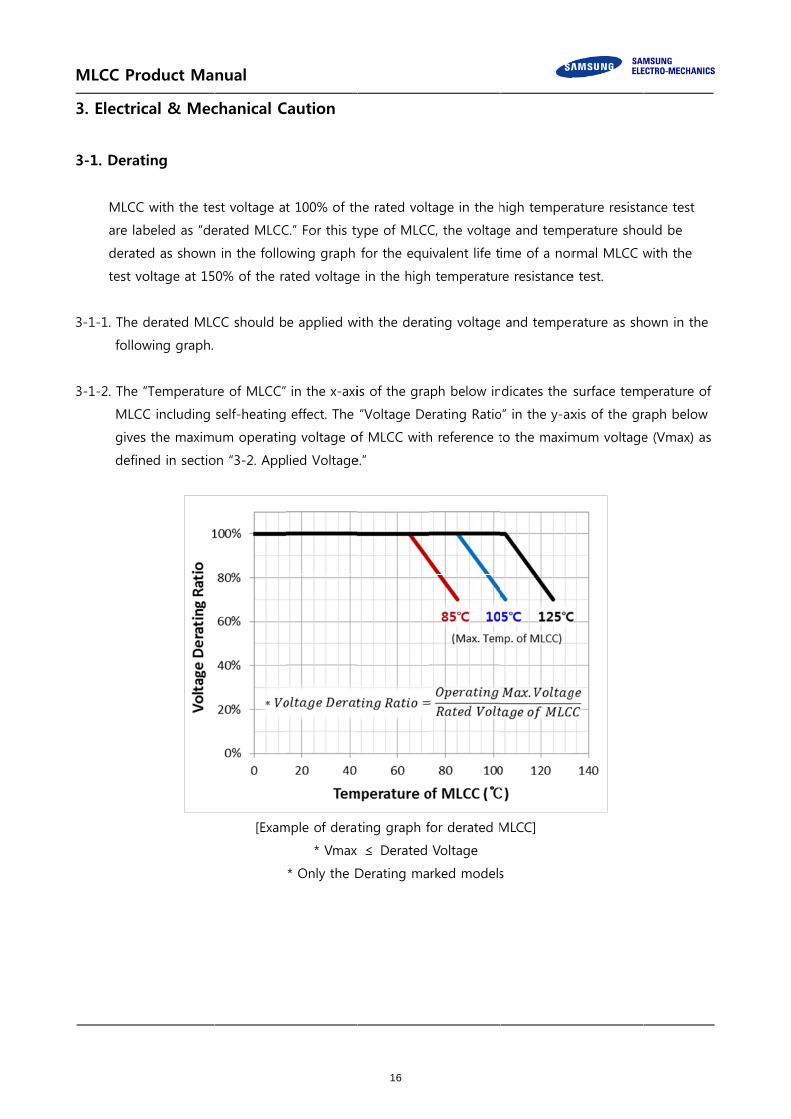
3. Electric
3-1. Derat
MLCC
are la
derate
test vo
3-1-1. The
follow
3-1-2. The
MLCC
gives
defin
oduct Ma
cal & Mec
ting
C with the te
beled as “de
ed as shown
oltage at 15
derated MLC
wing graph.
“Temperatur
C including
s the maxim
ned in sectio
nual
chanical C
st voltage at
erated MLCC
n in the follo
0% of the ra
CC should b
re of MLCC”
self-heating
um operatin
on “3-2. App
[Exam
Caution
t 100% of th
C.” For this ty
owing graph
ated voltage
be applied w
in the x-axi
effect. The
ng voltage o
lied Voltage
mple of derat
* Vmax
* Only the D
he rated volt
ype of MLCC
for the equ
e in the high
with the dera
is of the gra
“Voltage De
of MLCC with
e.”
ting graph f
≤ Derated
Derating ma
tage in the h
C, the voltag
ivalent life t
h temperatur
ting voltage
ph below in
erating Ratio
h reference t
for derated M
Voltage
rked models
high temper
ge and temp
ime of a nor
re resistance
and tempe
dicates the
o” in the y-ax
to the maxim
MLCC]
s
rature resista
perature sho
rmal MLCC w
e test.
rature as sh
surface tem
xis of the gr
mum voltage
ance test
uld be
with the
own in the
perature of
raph below
e (Vmax) as
16

MLCC Pro
3-2. Appli
The a
3-2-1. Caut
· For
no
· For
sho
· Abn
ML
DC Vo
3-2-2. Effec
· Elec
the
· Dow
diele
abou
· Plea
pre
(1) Surge
When
induc
electr
surge
(2) ESD
Since
comp
oduct Ma
ied Voltage
actual applie
tions by type
r DC voltage
ot exceed the
r AC voltage
ould not exc
normal volta
LCC.
oltage
ct of EOS (El
ctrical Overs
e electrical s
wn time of M
ectric shock c
ut a failure o
ase use caut
eparing MLC
e
n the overcu
ce the overs
rical short fa
e current into
(Electrostatic
e the voltage
pared to the
nual
e
ed voltage o
es of voltage
e or DC+AC
e rated volta
or pulse vo
ceed the rate
age such as
[Typ
AC Volta
ectrical Ove
stress such a
short failure
MLCC is vari
caused by E
of MLCC in a
tion not to a
CC for testing
urrent caused
hooting phe
ailure in MLC
o MLCC.
c Discharge)
e of the stat
surge, ESD
on MLCC sho
e applied to
voltage, DC
age of MLCC
oltage, the p
ed voltage o
surge voltag
pes of Voltag
ge DC
rstress)
as a surge vo
caused by t
ed with the
OS can acce
market at t
apply excess
g or evaluati
d by surge is
enomenon o
CC. Therefore
ic electricity
can cause d
ould not exc
MLCC
voltage or t
C.
eak-to-peak
of MLCC.
ge, static ele
ge Applied t
C+AC Voltag
oltage or EO
the dielectric
applied volt
elerate heati
the early sta
ive electrica
ing.
s applied to
of voltage as
e, it is neces
is very high
damage to M
ceed the rate
the maximum
k value of AC
ectricity shou
to the Capac
ge 1 DC+A
OS can cause
c breakdown
tage and the
ng on the d
ge.
l overstress
MLCC, the
shown in th
ssary to be c
h but the qu
MLCC with lo
ed voltage s
m value of D
C voltage or
uld not excee
citor]
AC Voltage 2
e damages to
n in MLCC.
e room temp
ielectric. The
including sp
influx of cur
he graph be
careful to pre
antity of ele
ow capacitan
set in the spe
DC + AC vol
pulse voltag
ed the rated
2 DC+Pul
o MLCC, res
perature and
erefore, it ca
pike voltage
rrent into ML
elow and res
revent the in
ectric charge
nce as shown
ecifications.
tage should
ge
d voltage of
se Voltage
ulting in
d a
an bring
MLCC when
LCC can
ult in the
flux of
is small
n in the
n
17

MLCC Pro
follow
high
[ Ex
3-3. Vibra
Pleas
Mana
Whe
and
3-4. Shock
Mecha
Do no
When
preven
3-5. Piezo
MLCC
consta
MLCC
oduct Ma
wing graph,
capacitance
xample of Su
ation
se check the
age MLCC n
n MLCC is u
consider spe
k
anical stress
ot use a drop
n piling up o
nt cracks or
o-electric P
may genera
ant MLCC (C
may cause
nual
whereas sur
MLCC.
urge applied
e types of vib
not to genera
used in a vib
ecial MLCC s
caused by a
pped MLCC
or handling p
any other d
henomeno
ate a noise d
Class Ⅱ) at A
a noise if M
rge with lots
to MLCC ]
bration and
ate resonanc
ration enviro
such as Soft-
a drop may
to avoid any
printed circu
damages to t
on
due to vibra
AC or Pulse c
MLCC is affec
s of electric c
shock, and
ce and avoid
onment, plea
-term, etc.
cause dama
y quality and
it boards, do
the MLCC.
tion at spec
circuits.
cted by any
charge quan
[ Example
the status o
d any kind o
ase make su
ages to a die
d reliability d
o not hit ML
ific frequenc
mechanical v
ntity can cau
of ESD appl
* Simulatio
f resonance.
of impact to
ure to contac
electric or a
deterioration
LCC with the
cy when usin
vibrations or
use damages
ied to MLCC
on for ESD 8
.
terminals.
ct us for the
crack in ML
n.
e corners of
ng the high
r shocks.
s to even
C ]
8kV
e situation
CC
a PCB to
dielectric
18

MLCC Pro
4. Proces
4-1. Moun
4-1-1. Mou
It is r
is ap
4-1-2. Caut
Pleas
PCB.
locat
4-1-3. Caut
If ML
Mou
oduct Ma
ss of Mou
nting
nting positio
recommend
pplied.
Not r
tions during
se take the f
Select the m
tion and a d
tions during
LCC is moun
nt MLCC as
nual
nting and
on
ed to locate
ecommende
mounting n
following me
mounting lo
irection of M
mounting n
nted near a s
far from the
N
d Soldering
e the major a
ed
near the cuto
easures to e
cation show
MLCC mount
near screw
screw hole, t
e screw hole
Not recomm
g
axis of MLCC
out
effectively red
wn below, sin
ted near the
the board d
es as possibl
mended
C in parallel
Reco
duce the str
nce the mech
e cutting line
eflection ma
e.
Recomm
to the direct
ommended
ess generate
hanical stres
e.
ay be occurre
ended
tion in whic
ed from the
ss is affected
red by screw
h the stress
cutting of
d by a
w torque.
19
MLCC Product Manual
4-2. Caution before Mounting
4-2-1. It is recommended to store and use MLCC in a reel. Do not re-use MLCC that was isolated from
the reel.
4-2-2. Check the capacitance characteristics under actual applied voltage.
4-2-3. Check the mechanical stress when actual process and equipment is in use.
4-2-4. Check the rated capacitance, rated voltage and other electrical characteristics before assembly.
Heat treatment must be done prior to measurement of capacitance.
4-2-5. Check the solderability of MLCC that has passed shelf life before use.
4-2-6. The use of Sn-Zn based solder may deteriorate the reliability of MLCC.
4-3. Cautions during Mounting with Mounting (pick-and-place) Machines
4-3-1. Mounting Head Pressure
Excessive pressure may cause cracks in MLCC.
It is recommended to adjust the nozzle pressure within the maximum value of 300g.f.
Additional conditions must be set for both thin film and special purpose MLCC.
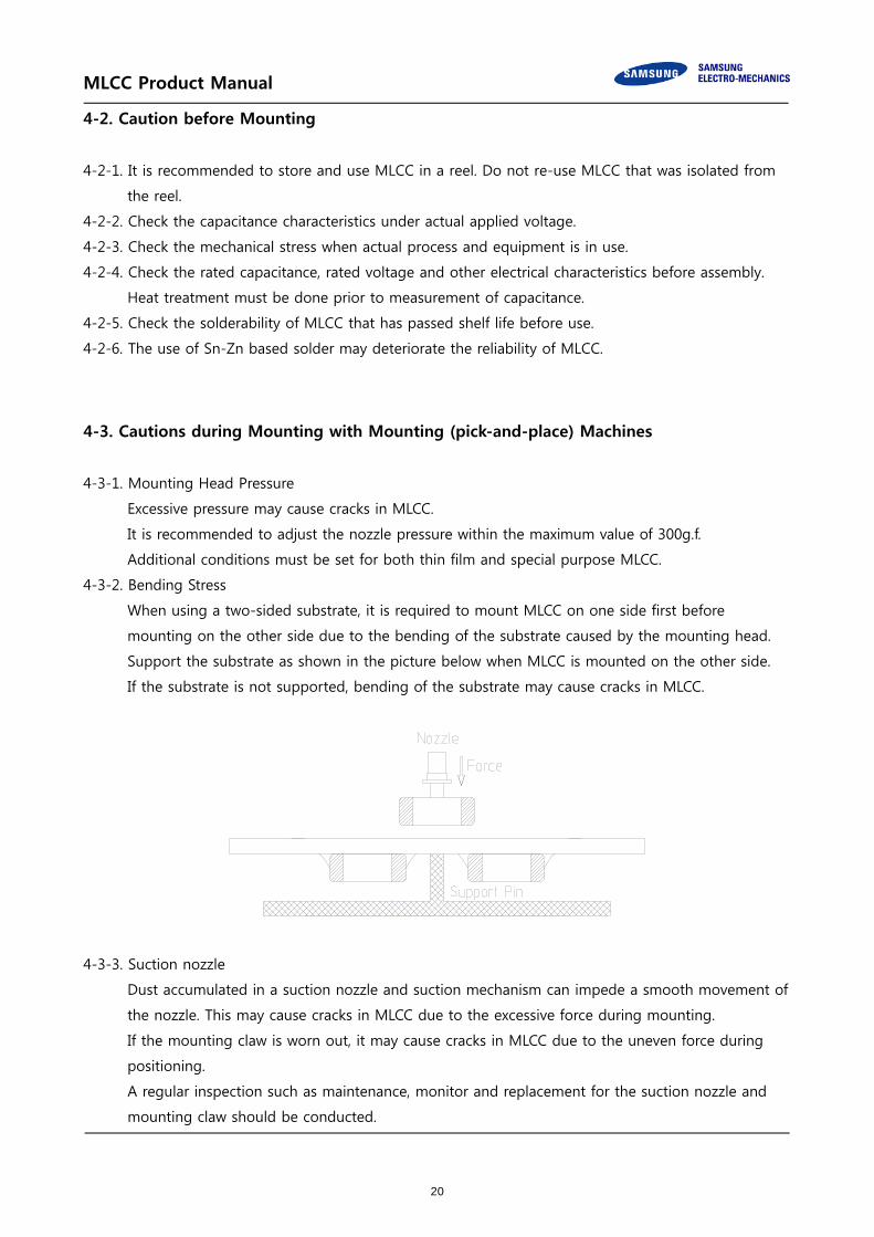
4-3-2. Bending Stress
When using a two-sided substrate, it is required to mount MLCC on one side first before
mounting on the other side due to the bending of the substrate caused by the mounting head.
Support the substrate as shown in the picture below when MLCC is mounted on the other side.
If the substrate is not supported, bending of the substrate may cause cracks in MLCC.
4-3-3. Suction nozzle
Dust accumulated in a suction nozzle and suction mechanism can impede a smooth movement of
the nozzle. This may cause cracks in MLCC due to the excessive force during mounting.
If the mounting claw is worn out, it may cause cracks in MLCC due to the uneven force during
positioning.
A regular inspection such as maintenance, monitor and replacement for the suction nozzle and
mounting claw should be conducted.
20

MLCC Pro
4-4. Reflo
MLCC
poten
Theref
For th
4-4-1. Reflo
Use c
Pre-h
on M
to th
As fo
three
times
MLCC
oduct Ma
ow solderin
is in a direc
ntial mechan
fore, MLCC m
he reason, th
Reflo
ow Profile
caution not
heating is ne
MLCC. The te
he minimum.
or reflow sol
e times. Plea
s. Care must
C as they ca
nual
ng
ct contact w
ical stress ca
may be cont
he mounting
M
ow soldering
to exceed th
ecessary for
emperature d
.
dering, it is
ase check wit
t be exercise
an be affecte
ith the disso
aused by the
taminated b
process mu
Method
g
Overa
Loca
[Reflow S
he peak tem
all constitue
difference be
recommend
th us when
ed especially
ed by therma
olved solder
e sudden tem
by the locatio
ust be closel
all heating
al heating
Soldering Co
mperature (26
ents includin
etween the
ded to keep
the number
y for the ultr
al stress mo
during sold
mperature c
on movemen
y monitored
C
In
VPS
L
onditions]
60℃) and tim
ng the PCB t
PCB and the
the number
of reflow so
ra-small size,
ore easily.
ering, which
hange.
nt and flux.
d.
lassification
nfrared rays
Hot plate
S(Vapor phas
Air heater
Laser
Light beam
me (30sec) a
o prevent th
e componen
r of reflow so
oldering nee
, thin film an
h may be ex
n
se)
as shown.
he mechanic
nt surface mu
oldering to
eds to excee
nd high cap
posed to
cal damages
ust be kept
less than
d three
acitance
21
MLCC Product Manual
4-4-2. Reflow temperature
The following quality problem may occur when MLCC is mounted with a lower temperature than
the reflow temperature recommended by a solder manufacturer. The specified peak temperature
must be maintained after taking into consideration the factors such as the placement of
peripheral constituent and the reflow temperature.
・Drop in solder wettability
・Solder voids
・Potential occurrence of whisker
・Drop in adhesive strength
・Drop in self-alignment properties
・Potential occurrence of tombstones
4-4-3. Cooling
Natural cooling with air is recommended.
4-4-4. Optimum solder flux for reflow soldering
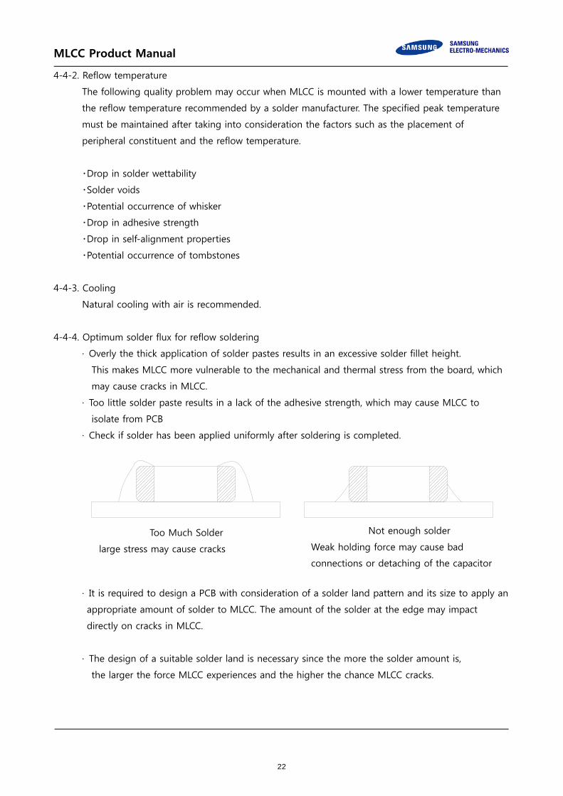
· Overly the thick application of solder pastes results in an excessive solder fillet height.
This makes MLCC more vulnerable to the mechanical and thermal stress from the board, which
may cause cracks in MLCC.
· Too little solder paste results in a lack of the adhesive strength, which may cause MLCC to
isolate from PCB
· Check if solder has been applied uniformly after soldering is completed.
· It is required to design a PCB with consideration of a solder land pattern and its size to apply an
appropriate amount of solder to MLCC. The amount of the solder at the edge may impact
directly on cracks in MLCC.
· The design of a suitable solder land is necessary since the more the solder amount is,
the larger the force MLCC experiences and the higher the chance MLCC cracks.
Too Much Solder
large stress may cause cracks
Not enough solder
Weak holding force may cause bad
connections or detaching of the capacitor
22
MLCC Pro
4-5. Flow
4-5-1. Flow
Ta
In
re
P
ex
4-5-2. Caut
· Wh
inter
the m
surfa
· If t
may
value
term
oduct Ma
soldering
w profile
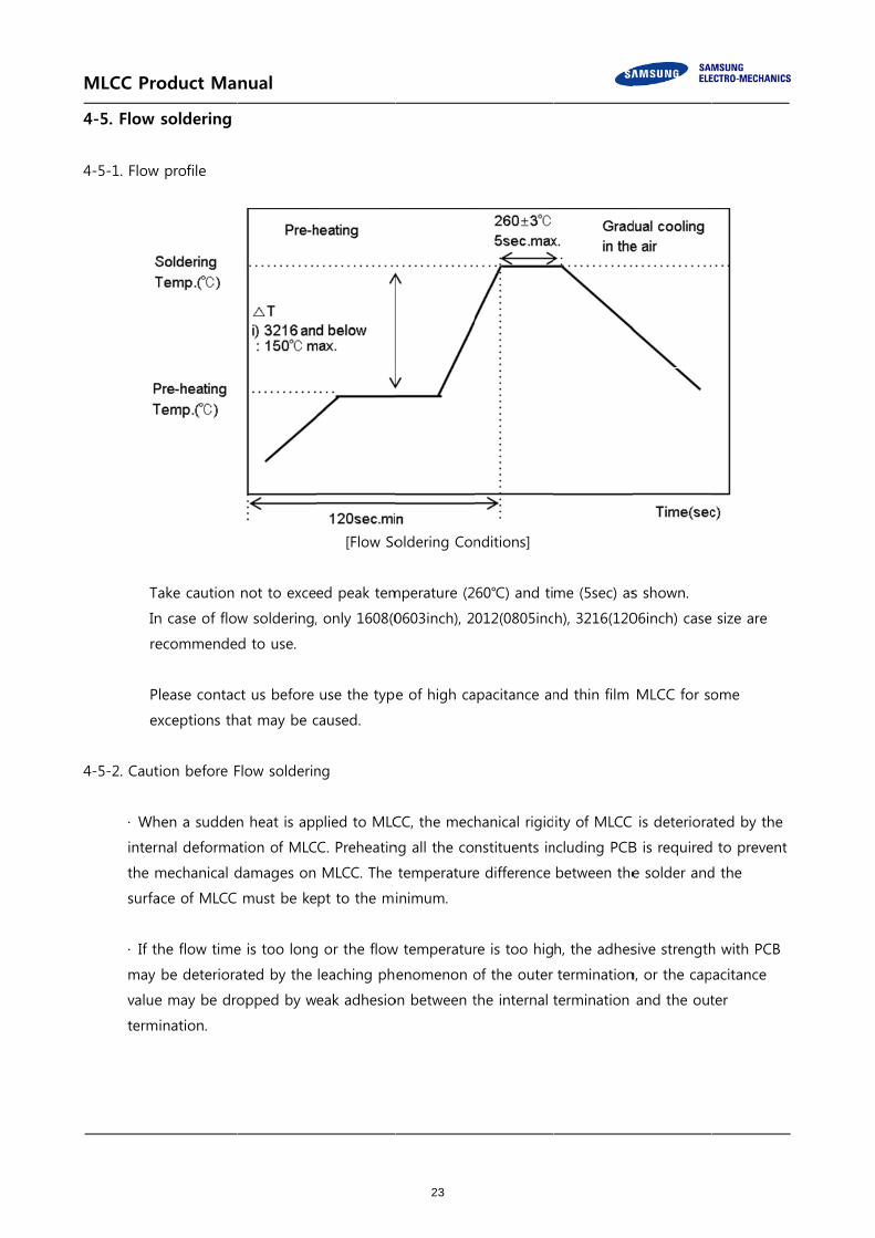
ake caution
n case of flo
ecommende
lease contac
xceptions th
tion before F
hen a sudden
nal deforma
mechanical d
ace of MLCC
he flow time
be deteriora
e may be dro
ination.
nual
not to exce
w soldering,
d to use.
ct us before
hat may be c
Flow solderin
n heat is ap
ation of MLC
damages on
must be ke
e is too long
ated by the
opped by w
[Flow So
ed peak tem
, only 1608(0
use the typ
caused.
ng
plied to MLC
CC. Preheatin
MLCC. The
pt to the m
g or the flow
leaching ph
eak adhesio
oldering Con
mperature (2
0603inch), 2
e of high ca
CC, the mec
ng all the co
temperature
inimum.
w temperatur
enomenon o
on between t
nditions]
60℃) and ti
012(0805inc
apacitance an
hanical rigid
nstituents in
e difference
re is too hig
of the outer
the internal
me (5sec) as
h), 3216(120
nd thin film
ity of MLCC
ncluding PCB
between the
h, the adhes
termination
termination
s shown.
06inch) case
MLCC for so
is deteriora
B is required
e solder and
sive strength
n, or the cap
and the out
size are
ome
ated by the
to prevent
d the
h with PCB
acitance
ter
23
MLCC Product Manual
4-6. Soldering Iron
Manual soldering can pose a great risk on creating thermal cracks in MLCC. The high temperature
soldering iron tip may come into a direct contact with the ceramic body of MLCC due to the
carelessness of an operator. Therefore, the soldering iron must be handled carefully, and close
attention must be paid to the selection of the soldering iron tip and to temperature control of the
tip.
4-6-1. How to use a soldering Iron
· In order to minimize damages on MLCC, preheating MLCC and PCB is necessary.
A hot plate and a hot air type preheater should be used for preheating
. Do not cool down MLCC and PCB rapidly after soldering.
· Keep the contact time between the outer termination of MLCC and the soldering iron as short as
possible. Long soldering time may cause problems such as adhesion deterioration by the
leaching phenomenon of the outer termination.
Variation of
Temp.
Soldering
Temp.(℃)
Pre-heating
Time(sec)
Soldering
Time(sec)
Cooling
Time(sec)
ΔT ≤ 130 300±10℃ max ≥60 ≤4 -
* Control Δ T in the solder iron and preheating temperature.
Condition of Iron facilities
Wattage Tip diameter Soldering time
20W max 3 ㎜ max 4sec max
* Caution - Iron tip should not contact with ceramic body directly
Lead-free solder: Sn-3.0Ag-0.5CU
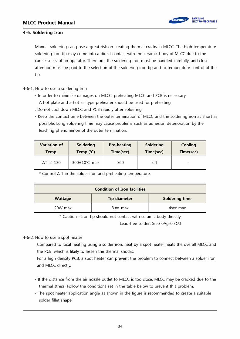
4-6-2. How to use a spot heater
Compared to local heating using a solder iron, heat by a spot heater heats the overall MLCC and
the PCB, which is likely to lessen the thermal shocks.
For a high density PCB, a spot heater can prevent the problem to connect between a solder iron
and MLCC directly.
· If the distance from the air nozzle outlet to MLCC is too close, MLCC may be cracked due to the
thermal stress. Follow the conditions set in the table below to prevent this problem.
· The spot heater application angle as shown in the figure is recommended to create a suitable
solder fillet shape.
24
MLCC Product Manual
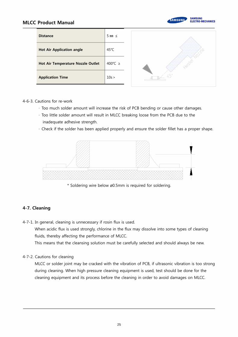
4-6-3. Cautions for re-work
· Too much solder amount will increase the risk of PCB bending or cause other damages.
· Too little solder amount will result in MLCC breaking loose from the PCB due to the
inadequate adhesive strength.
· Check if the solder has been applied properly and ensure the solder fillet has a proper shape.
* Soldering wire below ø0.5mm is required for soldering.
4-7. Cleaning
4-7-1. In general, cleaning is unnecessary if rosin flux is used.
When acidic flux is used strongly, chlorine in the flux may dissolve into some types of cleaning
fluids, thereby affecting the performance of MLCC.
This means that the cleansing solution must be carefully selected and should always be new.
4-7-2. Cautions for cleaning
MLCC or solder joint may be cracked with the vibration of PCB, if ultrasonic vibration is too strong
during cleaning. When high pressure cleaning equipment is used, test should be done for the
cleaning equipment and its process before the cleaning in order to avoid damages on MLCC.
Distance 5 ㎜ ≤
Hot Air Application angle 45℃
Hot Air Temperature Nozzle Outlet 400℃ ≥
Application Time 10s>
25

MLCC Product Manual
4-8. Cautions for using electrical measuring probes
· Confirm the position of the support pin or jig when checking the electrical performance of MLCC
after mounting on the PCB.
· Watch for PCB bending caused by the pressure of a test-probe or other equipment.
· If the PCB is bent by the force from the test probe, MLCC may be cracked or the solder joint may
be damaged.
· Avoid PCB flexing by using the support pin on the back side of the PCB.
· Place equipment with the support pin as close to the test-probe as possible.
· Prevent shock vibrations of the board when the test-probe contacts a PCB.
Not recommended Recommended
4-9. Printed Circuit Board Cropping
· Do not apply any stress to MLCC such as bending or twisting the board after mounting MLCC
on the PCB.
· The stress as shown may cause cracks in MLCC when cutting the board.
· Cracked MLCC may cause degradation to the insulation resistance, thereby causing short circuit.
· Avoid these types of stresses applied to MLCC.
[Bending] [Twisting]
4-9-1. Cautions for cutting PCB
Check a cutting method of PCB in advance.
The high density board is separated into many individual boards after the completion of soldering.
If the board is bent or deformed during separation, MLCC may be cracked.
Carefully select a separation method that minimizes the deformation of the PCB.
26

MLCC Product Manual
4-10. Assembly Handling
4-10-1. Cautions for PCB handling
Hold the edges of the board mounted with MLCC with both hands since holding with one hand
may bend the board.
Do not use dropped boards, which may degrade the quality of MLCC.
4-10-2. Mounting other components
Pay attention to the following conditions when mounting other components on the back side of
The board after MLCC has been mounted on the front side.
When the suction nozzle is placed too close to the board, board deflection stress may be
applied to MLCC on the back side, resulting in cracks in MLCC.
Check if proper value is set on each chip mounter for a suction location, a mounting gap and a
suction gap by the thickness of components.
4-10-3. Board mounting components with leads
If the board is bent when inserting components (transformer, IC, etc.) into it, MLCC or solder
joint may be cracked.
Pay attention to the following:
· Reduce the stress on the board during insertion by increasing the size of the lead insertion
hole.
· Insert components with leads into the board after fixing the board with support pins or a
dedicated jig.
· Support the bottom side of the board to avoid bending the board.
· Check the status of the height of each support pin regularly when the support pins are used.
Not recommended Recommended
27

MLCC Product Manual
4-10-4. Socket and / or connector attach / detach
Since the insertion or removal from sockets and connectors may cause the board to bent, make
sure that MLCC mounted on the board should not be damaged in this process.
4-10-5. Fastening screw
When attaching a shield on a board, the board may be bent during a screw tightening work
Pay attention to the following conditions before performing the work.
· Plan the work to prevent the board from bending
· Use a torque driver to prevent over-tightening of the screw.
· Since the board may be bent by soldering, use caution in tightening the screw.
4-11. Adhesive selection
Pay attention to the following if an adhesive is used to position MLCC on the board before
soldering.
4-11-1. Requirements for Adhesives
· They must have enough adhesive strength to prevent MLCC from slipping or moving during
the handling the board.
· They must maintain their adhesive strength when exposed to soldering temperatures.
· They should not spread when applied to the PCB.
· They should have a long pot life.
· They should hardened quickly.
· They should not corrode the board or MLCC materials.
· They should be an insulator type that does not affect the characteristic of MLCC.
· They should be non-toxic, not harmful, and particularly safe when workers touch the adhesives.
4-11-2. Caution before Applying Adhesive
Check the correct application conditions before attaching MLCC to the board with an adhesive.
If the dimension of land, the type of adhesives, the amount of coating, the contact surface areas,
the curing temperature, or other conditions are not appropriate, it may degrade the MLCC
performance.
28

MLCC Product Manual
4-11-3. Cautions for selecting Adhesive
Depending on the type of the chosen adhesive, MLCC insulation resistance may be degraded.
In addition, MLCC may be cracked by the difference in contractile stress caused by the different
contraction rate between MLCC and the adhesive.
4-11-4. Cautions for the amount of applied adhesive and curing temperature
· The inappropriate amount of the adhesive cause the weak adhesive strength, resulting in the a
mounting defect in MLCC
· Excessive use of the adhesive may cause a soldering defect, loss of electrical connection,
incorrect curing, or slippage of a mounting position, thereby an inflow of the adhesive onto a
land section should be avoided.
· If the curing temperature is too high or the curing time is too long, the adhesive strength will
be degraded. In addition, oxidation both on the outer termination (Sn) of MLCC and the
surface of the board may deteriorate the solderability.
4-12. Flux
4-12-1. The excessive amount of flux generates excessive flux gases which may deteriorate solderability.
Therefore, apply the flux thin and evenly as a whole.
4-12-2. Flux with a high ratio of halogen may oxidize the outer termination of MLCC, if cleaning is not
done properly. Therefore, use flux with a halogen content of 0.1% max.
4-12-3. Strong acidic flux can degrade the MLCC performance
4-12-4. Check the solder quality of MLCC and the amount of remaining flux surrounding MLCC after the
mounting process.
4-13. Coating
4-13-1. Crack caused by Coating
A crack may be caused in the MLCC due to amount of the resin and stress of thermal
contraction of the resin during coating process.
During the coating process, the amount of resin and the stress of thermal contraction of the
resin may cause cracks in MLCC
The difference of thermal expansion coefficient between the coating, or a molding resin may
cause destruction, deterioration of insulation resistance or dielectric breakdown of MLCC such
as cracks or detachment, etc.
29

MLCC Product Manual
4-13-2. Recommended Coating material
· A thermal expansion coefficient should be as close to that of MLCC as possible.
· A silicone resin can be used as an under-coating to buffer the stress.
· The resin should have a minimum curing contraction rate.
· The resin should have a minimum sensitivity (ex. Epoxy resin).
· The insulation resistance of MLCC can be deteriorated if a high hygroscopic property resin is
used in a high humidity condition.
· Do not use strong acid substances due to the fact that coating materials inducing a family of
halogen substances and organic acid may corrode MLCC.
30

MLCC Product Manual
5. Design
5-1. Circuit design
When the board is dropped or bent, MLCC mounted on the board may be short-circuited by the
drop in insulation resistance. Therefore, it is required to install safety equipment such as a fuse to
prevent additional accidents when MLCC is short-circuited, otherwise, electric short and fire may
occur. This product is not a safety guaranteed product..
5-2. PCB Design
5-2-1. Unlike lead type components, SMD type components that are designed to be mounted directly
on the board are fragile to the stress. In addition, they are more sensitive to mechanical and
thermal stress than lead type components.
5-2-2. MLCC crack by PCB material type
A great difference of the thermal expansion coefficient between PCB and MLCC causes thermal
expansion and contraction, resulting in cracks in MLCC. Even though MLCC is mounted on a
board with a fluorine resin or on a single-layered glass epoxy, cracks in MLCC may occur.
5-3. Design system evaluation
5-3-1. Evaluate the actual design with MLCC to make sure there is no functional issue or violation of
specifications of the finished goods.
5-3-2. Please note that the capacitance may differ based on the operating condition of the actual system
since Class 2 MLCC capacitance varies with applied voltage and temperature.
5-3-3. Surge resistance must be evaluated since the excessive surge caused by the inductance of the
actual system may apply to MLCC.
5-3-4. Note the actual MLCC size and the termination shape.
31

MLCC Pro
5-4 Land d
The rec
R
F
oduct Ma
dimension
commended
Reflow Foo
Chip Size
[mm]
0402
0603
1005
1608
2012
3216
3225
4532
5750
Flow Footp
Chip Size
[mm]
1608
2012
3216
nual
d land dimen
otprint
Chip Tol.
[mm]
± 0.02
± 0.03
± 0.05
± 0.07
± 0.09
± 0.05
± 0.07
± 0.10
± 0.15
± 0.20
± 0.30
± 0.40
± 0.10
± 0.15
± 0.20
± 0.25
± 0.30
±0.10
±0.15
±0.20
±0.25
±0.30
±0.20
±0.30
-
-
-
Chip Tol.
[mm]
-
-
-
nsion is dete
a
[mm]
0.14~0.20
0.16~0.20
0.18~0.26
0.20~0.28
0.22~0.30
0.35~0.40
0.37~0.42
0.40~0.45
0.40~0.45
0.45~0.50
0.45~0.50
0.50~0.55
0.50~0.55
0.55~0.60
0.60~0.65
0.65~0.70
0.70~0.75
0.70~0.75
0.75~0.80
0.80~0.85
0.85~0.90
0.90~0.95
1.70~1.90
1.80~2.00
2.00~2.40
2.80~3.20
4.00~4.60
a
[mm]
0.60~1.00
1.00~1.20
2.00~2.40
ermined by e
b
[mm]
0.14~0.22
0.24~0.32
0.24~0.32
0.25~0.35
0.25~0.35
0.37~0.47
0.37~0.47
0.37~0.47
0.40~0.50
0.40~0.50
0.42~0.52
0.45~0.55
0.60~0.65
0.62~0.67
0.65~0.70
0.70~0.75
0.75~0.80
0.75~0.80
0.80~0.85
0.85~0.90
0.95~1.00
1.05~1.10
0.85~1.00
0.95~1.10
1.00~1.40
1.40~1.80
1.70~2.30
b
[mm]
0.60~0.80
0.80~1.20
1.00~1.20
evaluating th
c
[mm]
0.20~0.26
0.30~0.35
0.32~0.37
0.35~0.39
0.35~0.39
0.50~0.55
0.52~0.58
0.55~0.60
0.60~0.65
0.65~0.70
0.70~0.75
0.75~0.80
0.80~0.85
0.85~0.90
0.90~0.95
0.95~1.00
1.00~1.05
1.25~1.30
1.30~1.35
1.35~1.40
1.40~1.45
1.45~1.50
1.60~1.80
1.70~1.90
1.80~2.20
2.40~3.00
4.10~4.90
c
[mm]
0.60~0.80
0.80~1.20
1.00~1.40
he actual SET
(a+2b)
min
0.42
0.64
0.66
0.7
0.72
1.09
1.11
1.14
1.2
1.25
1.29
1.4
1.7
1.79
1.9
2.05
2.2
2.2
2.35
2.5
2.75
3
3.4
3.7
4
5.6
7.4
(a+2b)
min
1.8
2.6
4.0
T and a boa
(a+2b)
max0.64
0.84
0.9
0.98
1
1.34
1.36
1.39
1.45
1.5
1.54
1.65
1.85
1.94
2.05
2.2
2.35
2.35
2.5
2.65
2.9
3.15
3.9
4.2
5.2
6.8
9.2
(a+2b)
max
2.6
3.6
4.8
rd.
32

MLCC Product Manual
6. Others
6-1. Storage environment
6-1-1. Recommendation for temperature/humidity
Even taping and packaging materials are designed to endure a long-term storage, they should
be stored with a temperature of 0~40°C and an RH of 0~70% otherwise, too high temperatures
or humidity may deteriorate the quality of the product rapidly.
As oxidization is accelerated when relative humidity is above 70%RH, the lower the humidity is,
the better the solderability is.
As the temperature difference may cause dew condensation during the storage of the product,
it is a must to maintain a temperature control environment
6-1-2. Shelf Life
An allowable storage period should be within 6 months from the outgoing date of delivery in
consideration of solderability. As for products in storage over 6 months, please check solderability
before use.
6-2. Caution for corrosive environment
As corrosive gases may deteriorate the solderability of MLCC outer termination, it is a must to
store MLCC in an environment without gases. MLCC that is exposed to corrosive gases may cause
its quality issues due to the corrosion of plating layers and the penetration of moisture.
6-3. Equipment in operation
6-3-1. Do not touch MLCC directly with bare hands to prevent an electric shock or damage.
6-3-2. The termination of MLCC shall not be contacted with a conductive object (short –circuit).
Do not expose MLCC to conductive liquid containing acidic or alkaline material.
6-3-3. Do not use the equipment in the following conditions.
(1) Exposure to water or oil
(2) Exposure to direct sunlight
33
MLCC Product Manual
(3) Exposure to Ozone or ultra-violet radiation.
(4) Exposure to corrosive gas (e.g. hydrogen sulfide, sulfur dioxide, chlorine, ammonia gas)
(5) Exposure to vibration or mechanical shock exceeding specified limit
(6) Exposure to high humidity
6-3-4. If the equipment starts generating any smoke, fire or smell, immediately switch it off or unplug
from the power source.
If the equipment is not switched off or unplugged, serious damage may occur due to the
continuous power supply. Please be careful with the high temperature in this condition.
6-4. Waste treatment
In case of scrapping MLCC, it is incinerated or buried by a licensed industrial waste company.
When scrapping MLCC, it is recommended to incinerate or bury the scrappage by a licensed
industrial waste company.
6-5. Operating temperature
The operating temperature limit is determined by the specification of each models.
6-5-1. Do not use MLCC over the maximum operating temperature.
Pay attention to equipment’s temperature distribution and the seasonal fluctuation of ambient
temperature.
6-5-2. The surface temperature of MLCC cannot exceed the maximum operating temperature including
self-heating effects.
6-6. Transportation
The performance of MLCC may be affected by transportation conditions.
6-6-1. MLCC shall be protected from excessive temperature, humidity and a mechanical force during
transportation.
34

MLCC Product Manual
During transportation, the cartons shall not be deformed and the inner packaging shall be
protected from excessive external forces.
6-6-2. Do not apply excessive vibrations, shocks or excessive forces to MLCC.
· If excessive mechanical shock or stress are applied, MLCC’s ceramic body may crack.
· When the surface of MLCC is hit with the sharp edge of an air driver, a soldering iron, or a
tweezer, etc, MLCC may crack or become short-circuited.
6-6-3. MLCC may crack and become non-functional due to the excessive shocks or dropping during
transportation.
6-7. Notice
Some special products are excluded from this document.
Please be advised that this is a standard product specification for a reference only.
We may change, modify or discontinue the product specifications without notice at any time.
So, you need to approve the product specifications before placing an order.
Should you have any question regarding the product specifications,
please contact our sales personnel or application engineers.
35

MLCC Product Manual
Caution of Application
Disclaimer
The products listed as follows are NOT designed and manufactured for any use and applications set
forth below.
Please note that any misuse of the products deviating from products specifications or information
provided in this Spec sheet may cause serious property damages or personal injury.
① Aerospace/Aviation equipment
② Automotive of Transportation equipment (vehicles,trains,ships,etc)
③ Military equipment
④ Atomic energy-related equipment
⑤ Undersea equipment
⑥ Any other applications with the same as or similar complexity or reliability to the applications
Limitation
Please contact us with usage environment information such as voltage, current, temperature, or other
special conditions before using our products for the applications listed below. The below application
conditions require especially high reliability products to prevent defects that may directly cause damages
or loss to third party's life, body or property.
If you have any questions regarding this 'Limitation',you should first contact our sales
personnel or application engineers.
① Medical equipment
② Disaster prevention/crime prevention equipment
③ Power plant control equipment
④ Traffic signal equipment
⑤ Data-processing equipment
⑥ Electric heating apparatus,burning equipment
⑦ Safety equipment
⑧ Any other applications with the same as or similar complexity or reliability to the applications
36