Embed Size (px)
Citation preview
Sitescan D-10+ & D-20+
User’s Guide
Version: 5
Version: 5


Sitescan D-10+ & D-20+ User’s Guide
Page i
Copyright © 2011 Sonatest Limited
All rights reserved. No part of this publication may be reproduced, stored in a retrieval system or transmitted in any form or by any means, electronic, mechanical, photocopying, recording or otherwise, without the prior written permission of Sonatest Limited.
Sonatest Limited Sonatest Inc. Dickens Road 12775 Cogburn Milton Keynes San Antonio MK12 5QQ Texas England 78249 Phone: +44 (0)1908 316345 USA Fax: +44 (0)1908 321323 Phone: +1 (210) 697 0335 e-mail: [email protected] Fax: +1 (210) 697 0767 Web: www.sonatest.com e-mail: [email protected]
Document Number: 147320 Issue 5 February 2012

Sitescan D-10+ & D-20+ User’s Guide ~ Contents
Page ii
Contents 1 How to Use This User’s Guide .............................................................................. 1
1.1 Typographical Conventions ....................................................................... 2 2 Disclaimers and Notices ...................................................................................... 3
2.1 Specific Warnings ..................................................................................... 3 2.2 General Warnings .................................................................................... 3 2.3 Operator Training .................................................................................... 3 2.4 Testing Limitations ................................................................................... 4 2.5 Critical Operating Factors .......................................................................... 4
2.5.1 Calibration of the Sound Velocity ........................................................... 4 2.5.2 Transducer (Probe) Zero Procedure ....................................................... 4 2.5.3 Flaw Detection Calibration .................................................................... 4 2.5.4 Effects of Temperature on Calibration .................................................... 5 2.5.5 Transducer Condition ........................................................................... 5 2.5.6 Use of Couplant ................................................................................... 5
2.6 Disclaimer of Liability ............................................................................... 6 2.7 Electromagnetic Compatibility ................................................................... 6
3 Quick Start ........................................................................................................ 7 3.1 Front Panel .............................................................................................. 7 3.2 Flaw Detection ........................................................................................ 13 3.3 Thickness Gauging .................................................................................. 14 3.4 Sitescan D-10+ & D-20+ Memory ............................................................. 15
3.4.1 Reset to factory defaults ..................................................................... 15 3.4.2 Clearing the Memory ........................................................................... 15
4 Detailed Menu Description ................................................................................. 17 4.1 Menu Tree.............................................................................................. 17 4.2 Main Menu ............................................................................................. 19
4.2.1 Main Menu Selection ........................................................................... 19 4.3 CAL Menu .............................................................................................. 20
4.3.1 Calibration Menu ................................................................................ 20 4.3.2 Amplifier Menu ................................................................................... 20 4.3.3 TX Menu ............................................................................................ 21 4.3.4 GATE1 & GATE2 Menus ....................................................................... 21 4.3.5 Auto-Cal Menu ................................................................................... 22
4.4 MEAS Menu ............................................................................................ 23 4.4.1 Measurement Menu ............................................................................ 23 4.4.2 TRIG ................................................................................................. 24 4.4.3 PROBE Menu ...................................................................................... 24 4.4.4 T-COMP ............................................................................................. 25 4.4.5 BSCAN (Optional Feature) ................................................................... 25 4.4.6 AGC (Automatic Gain Control) .............................................................. 26 4.4.7 TCG Time Corrected Gain Menu (D-20+ Only) ....................................... 27 4.4.8 Distance Amplitude Correction (DAC) Menu (Optional Feature) ............... 28 4.4.9 AWS Menu (Optional Feature).............................................................. 29 4.4.10 API Menu (Optional Feature) ............................................................... 30 4.4.11 DGS/AVG (Optional Feature) ................................................................ 31

Sitescan D-10+ & D-20+ User’s Guide ~ Contents
Page iii
4.5 MEMORY Menu ....................................................................................... 33 4.5.1 PANEL Memory Menu .......................................................................... 33 4.5.2 A-LOG Memory Menu .......................................................................... 34 4.5.3 REF Menu .......................................................................................... 34 4.5.4 B-LOG Memory Menu .......................................................................... 35 4.5.5 T-LOG Mode - Off Mode ...................................................................... 36 4.5.6 T-LOG Mode - Logging Mode ............................................................... 36 4.5.7 T-LOG Menu - Review Mode ................................................................ 36
4.6 UTIL Menu ............................................................................................. 37 4.6.1 MENU Menu ....................................................................................... 37 4.6.2 VIDEO Menu ...................................................................................... 37 4.6.3 MISC Menu ........................................................................................ 38 4.6.4 PRINT Menu ...................................................................................... 38 4.6.5 CLOCK Menu ...................................................................................... 39 4.6.6 U-KEYS Menu ..................................................................................... 39
4.7 Storage & Recall of Calibration Setups ...................................................... 41 4.7.1 To store a panel set: ........................................................................... 41 4.7.2 Thumbnail Viewer ............................................................................... 42 4.7.3 To recall a panel set: .......................................................................... 42 4.7.4 To delete a panel set: ......................................................................... 42 4.7.5 Adding NOTES to PANEL, A-LOG and B-LOG sets ................................... 43 4.7.6 Using the Optional Keyboard ............................................................... 44 4.7.7 Entering License Key to Activate Options .............................................. 45
5 Flaw Testing ..................................................................................................... 47 5.1 Basic Flaw Testing .................................................................................. 47 5.2 Flaw Testing Calibration .......................................................................... 48 5.3 TCG Operation (D-20+ Only) ................................................................... 51 5.4 DAC Operation (Optional Feature) ............................................................ 53 5.5 Weld Inspection Using the AWS Menu (Optional Feature) ........................... 56 5.6 Evaluating Pipe Imperfections ~ API 5UE (Optional Feature) ...................... 59 5.7 DGS/AVG Operation (Optional Feature) ..................................................... 62
5.7.1 Theory .............................................................................................. 62 5.7.2 DGS/AVG Frequency, NFL and ERS ...................................................... 63 5.7.3 DGS/AVG T-Loss, Ref dB and Mat dB .................................................... 64 5.7.4 DGS/AVG dVK, REF TYPE and REFSIZE ................................................. 65 5.7.5 DGS/AVG Calibration (SET SIG) ........................................................... 66 5.7.6 Adjustment ........................................................................................ 67 5.7.7 Measurement ..................................................................................... 69
5.8 Weld Inspection Using Trigonometry Mode ............................................... 70 5.9 B-Scan Measurement Technique .............................................................. 72
5.9.1 Overview ........................................................................................... 72 5.9.2 Configuring B-Scan Measurement Mode ................................................ 72 5.9.3 Using B-Scan Mode ............................................................................. 73
5.10 Temperature Compensation ..................................................................... 75 5.10.1 Overview ........................................................................................... 75 5.10.2 The Calculation .................................................................................. 75 5.10.3 Configuring Temperature Compensation ............................................... 75 5.10.4 Using Temperature Compensation ....................................................... 76
Sitescan D-10+ & D-20+ User’s Guide ~ Contents
Page iv
5.11 Flank – Flank Measurement Mode ............................................................. 78 5.11.1 Overview ........................................................................................... 78 5.11.2 Setting up Flank - Flank Mode .............................................................. 78 5.11.3 Using Flank - Flank Mode .................................................................... 79
6 A-LOG, A-Scan Storage ...................................................................................... 80 6.1.1 To Store An A-Scan: ........................................................................... 80 6.1.2 Thumbnail Viewer ............................................................................... 81 6.1.3 To Recall an A-Scan: ........................................................................... 81 6.1.4 To Delete a Stored A-Scan................................................................... 82 6.1.5 REF, Reference Waveform Comparisons ............................................... 82 6.1.6 To Recall an A-Scan as a Reference Waveform: ..................................... 82 6.1.7 Peak Echo & Hold Dynamics ................................................................ 83
7 B-Log, B-Scan Storage ....................................................................................... 85 8 Thickness Gauging ............................................................................................ 87
8.1 Basic Thickness Gauging .......................................................................... 87 8.2 Auto-Cal ................................................................................................. 90 8.3 TCG for Reliable Gauging ......................................................................... 91 8.4 Advanced Thickness Mode - Initial Overview ............................................. 92 8.5 Thickness Logging Without Advanced Thickness ........................................ 92 8.6 Using Advanced TLOG Mode .................................................................... 93
8.6.1 Setting up an inspection plan on the DFD ............................................. 93 8.6.2 Thickness Logging .............................................................................. 98 8.6.3 Review Mode ................................................................................... 100 8.6.4 B-Scan’s .......................................................................................... 101 8.6.5 Old Readings .................................................................................... 102 8.6.6 Sequence Mode ................................................................................ 103 8.6.7 Customised Row / Column Titles ........................................................ 104
9 Upgrading to Version 3 Software ...................................................................... 105 9.1 FPGA Version: ...................................................................................... 105 9.2 Memory Stores: .................................................................................... 105
10 Battery ........................................................................................................... 106 10.1 Battery Cautions ................................................................................... 106 10.2 Battery Charging ................................................................................... 108
Charging Caution ............................................................................................ 108 11 Interface Connections ...................................................................................... 110
11.1 USB ..................................................................................................... 110 11.2 Composite Video ................................................................................... 110
12 Features of the Sitescan D-10+ & D-20+ .......................................................... 111 Functional Testing Methods ................................................................................. 111
13 Specifications .................................................................................................. 112 14 Warranty ........................................................................................................ 114 Index .................................................................................................................... 115

Sitescan D-10+ & D-20+ User’s Guide ~ How to Use This User’s Guide
Page 1
1 How to Use This User’s Guide This user’s guide has been designed so that a person with a good knowledge of the basics of ultrasonic non-destructive testing may understand the operation and use of the features offered by the Sitescan D-10+ & D-20+. The user is advised, however, of the important nature of ultrasonic non-destructive testing and is referred to Section 2 for important information on the proper use of this technology.
Section 1: How to Use This User’s Guide is this section.
Section 2: Disclaimers and Notices contains important information that must be understood by users of the Sitescan D-10+ & D-20+
Section 3: Quick Start provides a user familiar with ultrasonic testing a means to operate the instrument’s basic functions and to quickly achieve
familiarity without having to understand all of its features in detail.
Section 4: Detailed Menu Description is an in-depth description of the menu items found in the Sitescan D-10+ & D-20+ with brief descriptions of each item.
Section 5: Flaw Testing gives guidelines on performing flaw testing with examples of how to calibrate the Sitescan D-10+ & D-20+ and how to set up the unit for DAC and TCG and how to use the A-Scan storage facilities.
Section 6: A-LOG, A-Scan Storage describes the process of storing, recalling A-Scans on the Sitescan D-10+ & D-20+. It includes loading a waveform and displaying as a reference trace on the display.
Section 7: B-Log, B-Scan Storage describes the process of storing and recalling B-Scans on the Sitescan D-10+ & D-20+.
Section 8: Thickness Gauging gives guidelines on performing thickness measurements including the calibration of the Sitescan D-10+ & D-20+, using TCG and how to use the thickness measurement memory functions.
Section 9: Upgrading to Version 3 Software describes the actions needed if upgrading the D-10+ & D-20+ from and older version of software to version 3
Section 10: Battery describes important aspects of using and caring for the battery.
Section 11: Interface Connections is for users who desire to operate the Sitescan D-10+ & D-20+ with ancillary equipment.
Section 12: Features of the Sitescan D-10+ & D-20+ is a quick reference listing the pertinent characteristics of the instrument and the various functional testing methods that may be used with the instrument.
The function keys are shown throughout this manual as shown in Section 3.1, Front Panel.

Sitescan D-10+ & D-20+ User’s Guide ~ How to Use This User’s Guide
Page 2
1.1 Typographical Conventions
When describing front panel buttons the text is printed in this font.
When describing settings in the Sitescan D-10+ & D-20+ the text is. printed in
this font

Sitescan D-10+ & D-20+ User’s Guide ~ Disclaimers and Notices
Page 3
2 Disclaimers and Notices The following information must be read and understood by users of the Sonatest Sitescan D-10+ & D-20+ ultrasonic flaw detector and thickness gauge. Failure to follow these instructions can lead to serious errors in test results or damage to the flaw detector. Decisions based on erroneous results can lead to property damage, personal injury or death. Anyone using this instrument should be fully qualified by their organization in the theory and practice of ultrasonic testing, or under the direct supervision of such a person.
2.1 Specific Warnings
The Sitescan D-10+ & D-20+ contains a high-energy, precision pulser allowing optimum testing results to be obtained by matching the pulse width to the probe characteristics. This circuitry may be damaged by voltage spikes. It is recommended that the instrument
be switched off, or the pulser stopped (by pressing the FREEZEPEAK
key) before changing transducers (probes).
2.2 General Warnings
Proper use of the ultrasonic test equipment requires three essential elements:
Knowledge of the specific test or inspection and applicable test equipment.
Selection of the correct test equipment based on knowledge of the application.
Competent training of the instrument operator.
This user’s guide provides instruction in the basic operation of the Sitescan D-10+ & D-20+ flaw detector. In addition to the methods included, many other factors can affect the
use of this flaw detector. Specific information regarding these factors is beyond the scope of this manual. The user should refer to appropriate textbooks on the subject of ultrasonic testing and thickness gauging for more detailed information.
2.3 Operator Training
Operators must receive adequate training before using this ultrasonic flaw detector. Operators must be trained in general ultrasonic testing procedures and in the set-up and performance required by each specific test or inspection. Operators must understand:
Sound wave propagation theory.
Effects of the velocity of sound in the test material.
Behaviour of the sound wave at the interface of two different materials.
Sound wave spread and mode conversion.
More specific information about operator training, qualification, certification and test specifications can be obtained from technical societies, industry groups and government agencies.
Sitescan D-10+ & D-20+ User’s Guide ~ Disclaimers and Notices
Page 4
2.4 Testing Limitations
In ultrasonic testing, information is obtained only from within the confines of the sound
beam as it propagates into the test material. Operators must exercise great caution when making inferences about the nature of the test material outside the limits of the sound beam. The condition of materials can vary significantly and the results can be erratic if operators don’t exercise good judgment.
2.5 Critical Operating Factors
The following procedures must be observed by all users of this ultrasonic flaw detector in order to obtain proper and accurate results.
2.5.1 Calibration of the Sound Velocity
An ultrasonic flaw detector operates on the principle of measuring the time of flight of a
burst of high frequency sound through the test piece as well as evaluating the amplitude of reflected or transmitted echoes. The sound velocity of the test piece multiplies this time in order to obtain an accurate distance or thickness reading. Since the actual sound velocity in materials can vary from the published values, the best result is obtained when the instrument is calibrated on a reference block made from the same material as the test piece. This block should be flat, smooth and as thick as the maximum thickness expected of the test piece.
Users should also be aware that the sound velocity might not be constant throughout the test piece due to effects such as heat-treating. This must be taken into consideration when evaluating the results of ultrasonic thickness testing. The calibration should always be checked after testing to minimize errors.
2.5.2 Transducer (Probe) Zero Procedure
The transducer calibration procedures must be performed as described in this manual. The calibration block must be clean, in good condition and free of noticeable wear. Failure to perform the transducer zero and calibration procedure will cause inaccurate thickness readings.
2.5.3 Flaw Detection Calibration
When performing flaw detection, it is important to note that the amplitude of indications is not only related to the size of the discontinuity; the depth of a discontinuity below the test piece surface will also have an effect on the amplitude due to characteristics of the sound beam spread and near field zone of the transducer. In addition, the characteristics of the discontinuity such as orientation and classification can alter the expected amplitude
response. For these reasons, calibration should be performed on test blocks made of the same material as the test piece with artificial discontinuities within the range of size and depth in the material to be detected. The user is again cautioned to refer to reference books which are beyond the scope of this manual.

Sitescan D-10+ & D-20+ User’s Guide ~ Disclaimers and Notices
Page 5
2.5.4 Effects of Temperature on Calibration
The sound velocity in test pieces and the transducer wear face changes with temperature
variations. All calibrations should be performed on site with test blocks at or near the same temperature as that expected on the test piece, to minimize errors.
2.5.5 Transducer Condition
The transducer used for testing must be in good condition, without noticeable wear of the front surface. The specified range of the transducer must encompass the complete range of the thickness to be tested and/or the types of discontinuities to be investigated. The temperature of the material to be tested must be within the transducer’s specified temperature range.
2.5.6 Use of Couplant
Operators must be familiar with the use of ultrasonic couplant. Testing skills must be developed so that couplant is used and applied in a consistent manner to eliminate variations in couplant thickness which can cause errors and inaccurate readings. Calibration and actual testing should be performed under similar coupling conditions, using a minimum amount of couplant and applying consistent pressure to the transducer.

Sitescan D-10+ & D-20+ User’s Guide ~ Disclaimers and Notices
Page 6
2.6 Disclaimer of Liability
All statements, technical information and recommendations contained in this manual or any other information supplied by Sonatest Limited in connection with the use, features and qualifications of the Sitescan D-10+ & D-20+ are based on tests believed to be reliable, but the accuracy or completeness thereof is not guaranteed. Before using the product you should determine its suitability for your intended use based on your knowledge of ultrasonic testing and the characteristics of materials. You bear all risk in connection with the use of the product.
You are reminded that all warranties as to merchantability and fitness for purpose are excluded from the contract under which the product and this manual have been supplied to you. The Seller’s only obligation in this respect is to replace such quantity of the product proved to be defective.
Neither the seller nor the manufacturer shall be liable either in contract or in tort for any direct or indirect loss or damage (whether for loss of profit or otherwise), costs, expenses or other claims for consequential or indirect compensation whatsoever (and whether caused by the negligence of the company, its employees or agents or otherwise).
2.7 Electromagnetic Compatibility
This product conforms to the following European Directives:
Directive 2002/95/EC on the Restriction of the Use of certain Hazardous Substances in Electrical and Electronic Equipment (RoHS)
Directive 2002/96/EC on Waste Electrical and Electronic Equipment (WEEE)
Low Voltage Directive (LVD) 73/23/EEC
CE Marking Directive 93/68/EEC
EMC Directive 89/336/EEC. However, in order to ensure the equipment meets the requirements, the following should be read:
WARNING! This is a “CLASS A” product. In a domestic environment, this product may cause radio interference. In which case the user may be required to take adequate measures.
Note: This product should not be connected to cables greater than three (3) meters in length. If this is necessary, the installation may require further EMC testing to ensure conformity.
The Sitescan D-10+ & D-20+ also complies with EN 12668-1, Non-destructive testing and verification of ultrasonic examination equipment – Part 1: Instruments. For any questions relating to the proper use of this product, please contact the manufacturer at the number indicated on page i.
Sitescan D-10+ & D-20+ User’s Guide ~ Quick Start
Page 7
3 Quick Start
3.1 Front Panel
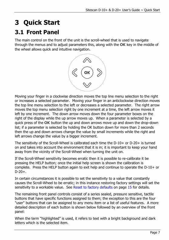
The main control on the front of the unit is the scroll-wheel that is used to navigate
through the menus and to adjust parameters this, along with the OK key in the middle of
the wheel allows quick and intuitive navigation.
Moving your finger in a clockwise direction moves the top line menu selection to the right or increases a selected parameter. Moving your finger in an anticlockwise direction moves the top line menu selection to the left or decreases a selected parameter. The right arrow moves the top menu selection right by one increment at a time, the left arrow moves it left by one increment. The down arrow moves down the four parameter boxes on the right of the display while the up arrow moves up. When a parameter is selected by a
quick press of the OK button the up and down arrows move up and down the drop-down
list; if a parameter is selected by holding the OK button down for more than 2 seconds then the up and down arrows change the value by small increments while the right and left arrows change the value by a bigger increment.
The sensitivity of the Scroll-Wheel is calibrated each time the D-10+ or D-20+ is turned on and takes into account the environment that it is in; it is important to keep your hand away from the vicinity of the Scroll-Wheel when turning the unit on.
If the Scroll-Wheel sensitivity becomes erratic then it is possible to re-calibrate it be pressing the HELP button; once the initial help screen is shown the calibration is complete. Press the HELP button again to exit help and continue to operate the D-10+ or D-20+.
In certain circumstances it is possible to set the sensitivity to a value that constantly causes the Scroll-Wheel to be erratic; in this instance restoring factory settings will set the sensitivity to a workable value. See Reset to factory defaults on page 15 for details.
The remaining front panel controls consist of a series sealed, pressure sensitive, tactile buttons that have specific functions assigned to them; the exception to this are the four "user" buttons that can be assigned to any menu item or a list of useful features. A more detailed description of each button is shown below followed by an overview of the front panel:
When the term “highlighted” is used, it refers to text with a bright background and dark letters which is the selected item.
Sitescan D-10+ & D-20+ User’s Guide ~Quick Start
Page 8
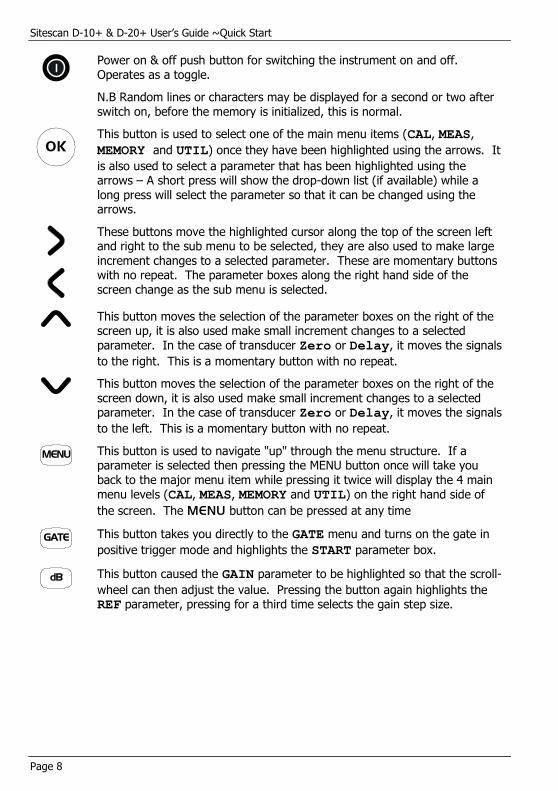
Power on & off push button for switching the instrument on and off. Operates as a toggle.
N.B Random lines or characters may be displayed for a second or two after switch on, before the memory is initialized, this is normal.
OK
This button is used to select one of the main menu items (CAL, MEAS,
MEMORY and UTIL) once they have been highlighted using the arrows. It
is also used to select a parameter that has been highlighted using the arrows – A short press will show the drop-down list (if available) while a long press will select the parameter so that it can be changed using the arrows.
These buttons move the highlighted cursor along the top of the screen left and right to the sub menu to be selected, they are also used to make large increment changes to a selected parameter. These are momentary buttons with no repeat. The parameter boxes along the right hand side of the screen change as the sub menu is selected.
This button moves the selection of the parameter boxes on the right of the screen up, it is also used make small increment changes to a selected parameter. In the case of transducer Zero or Delay, it moves the signals
to the right. This is a momentary button with no repeat.
This button moves the selection of the parameter boxes on the right of the screen down, it is also used make small increment changes to a selected parameter. In the case of transducer Zero or Delay, it moves the signals
to the left. This is a momentary button with no repeat.
MENU
This button is used to navigate "up" through the menu structure. If a parameter is selected then pressing the MENU button once will take you back to the major menu item while pressing it twice will display the 4 main menu levels (CAL, MEAS, MEMORY and UTIL) on the right hand side of
the screen. The MENU button can be pressed at any time
GATE
This button takes you directly to the GATE menu and turns on the gate in
positive trigger mode and highlights the START parameter box.
dB
This button caused the GAIN parameter to be highlighted so that the scroll-
wheel can then adjust the value. Pressing the button again highlights the REF parameter, pressing for a third time selects the gain step size.
Sitescan D-10+ & D-20+ User’s Guide ~ Quick Start
Page 9
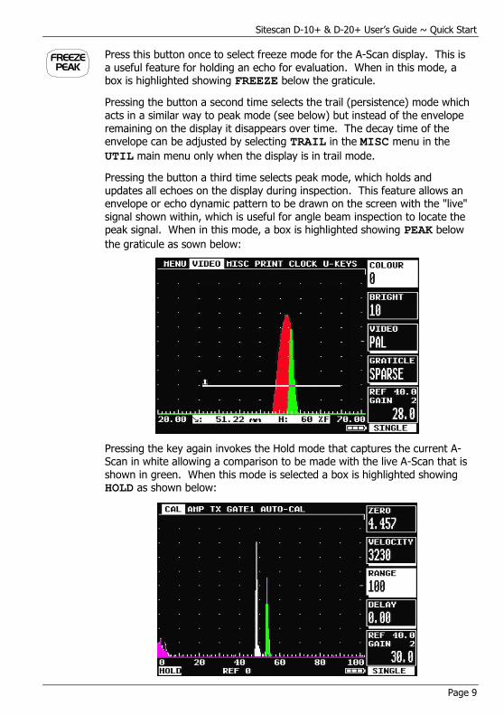
FREEZEPEAK
Press this button once to select freeze mode for the A-Scan display. This is a useful feature for holding an echo for evaluation. When in this mode, a box is highlighted showing FREEZE below the graticule.
Pressing the button a second time selects the trail (persistence) mode which acts in a similar way to peak mode (see below) but instead of the envelope remaining on the display it disappears over time. The decay time of the envelope can be adjusted by selecting TRAIL in the MISC menu in the
UTIL main menu only when the display is in trail mode.
Pressing the button a third time selects peak mode, which holds and updates all echoes on the display during inspection. This feature allows an envelope or echo dynamic pattern to be drawn on the screen with the "live" signal shown within, which is useful for angle beam inspection to locate the peak signal. When in this mode, a box is highlighted showing PEAK below
the graticule as sown below:
Pressing the key again invokes the Hold mode that captures the current A-Scan in white allowing a comparison to be made with the live A-Scan that is shown in green. When this mode is selected a box is highlighted showing HOLD as shown below:
Sitescan D-10+ & D-20+ User’s Guide ~Quick Start
Page 10
Pressing the button a fourth time returns the A-Scan display to normal mode. This is a momentary button with no repeat action.
Any of the freeze, peak or hold modes can be exited quickly by pressing and
holding the FREZE / PEAK key.
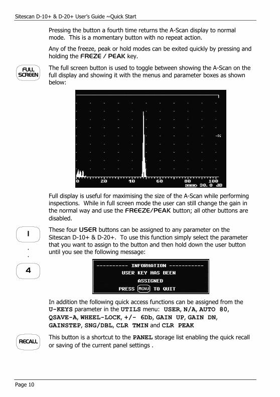
FULLSCREEN
The full screen button is used to toggle between showing the A-Scan on the full display and showing it with the menus and parameter boxes as shown below:
Full display is useful for maximising the size of the A-Scan while performing inspections. While in full screen mode the user can still change the gain in
the normal way and use the FREEZE/PEAK button; all other buttons are
disabled.
1
.
.
4
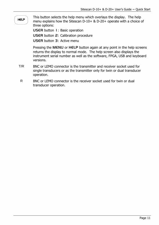
These four USER buttons can be assigned to any parameter on the
Sitescan D-10+ & D-20+. To use this function simply select the parameter that you want to assign to the button and then hold down the user button until you see the following message:
In addition the following quick access functions can be assigned from the U-KEYS parameter in the UTILS menu: USER, N/A, AUTO 80,
QSAVE-A, WHEEL-LOCK, +/- 6Db, GAIN UP, GAIN DN,
GAINSTEP, SNG/DBL, CLR TMIN and CLR PEAK
RECALL
This button is a shortcut to the PANEL storage list enabling the quick recall
or saving of the current panel settings .
Sitescan D-10+ & D-20+ User’s Guide ~ Quick Start
Page 11
HELP
This button selects the help menu which overlays the display. The help menu explains how the Sitescan D-10+ & D-20+ operate with a choice of three options:
USER button 1: Basic operation
USER button 2: Calibration procedure
USER button 3: Active menu
Pressing the MENU or HELP button again at any point in the help screens
returns the display to normal mode. The help screen also displays the instrument serial number as well as the software, FPGA, USB and keyboard versions.
T/R BNC or LEMO connector is the transmitter and receiver socket used for single transducers or as the transmitter only for twin or dual transducer operation.
R BNC or LEMO connector is the receiver socket used for twin or dual transducer operation.
Sitescan D-10+ & D-20+ User’s Guide ~Quick Start
Page 12
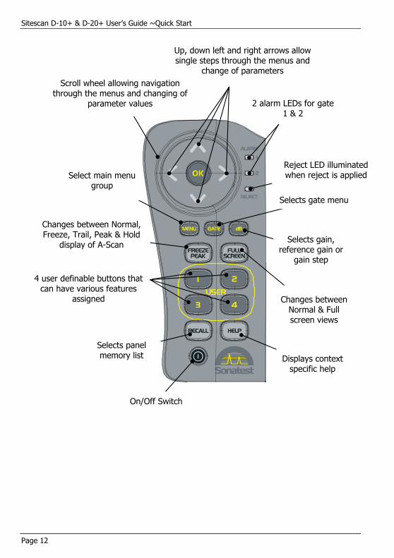
Displays context specific help
Select main menu group
On/Off Switch
Changes between Normal & Full screen views
Changes between Normal, Freeze, Trail, Peak & Hold
display of A-Scan
4 user definable buttons that can have various features
assigned
Up, down left and right arrows allow single steps through the menus and
change of parameters
Selects gain, reference gain or
gain step
Selects gate menu
2 alarm LEDs for gate 1 & 2
Reject LED illuminated when reject is applied
Selects panel memory list
Scroll wheel allowing navigation through the menus and changing of
parameter values
Sitescan D-10+ & D-20+ User’s Guide ~ Quick Start
Page 13
3.2 Flaw Detection
Perform the following steps to establish a basic flaw detection mode for the Sitescan D-10+ & D-20+. Units shown are in inches. For inch units, select INCHES from the UTIL
menu and use the corresponding values for the parameters.
1. Select a suitable transducer, preferably a 5MHz, 10mm diameter narrow band.
2. In the CAL menu, set the following parameters:
ZERO to 0.000
VELOCITY should be set the specimen material velocity.
RANGE to 125 or other suitable value to cover the test range of interest.
DELAY to 0.000
GAIN to 50.0
3. In the AMP menu, set the following parameters:
FREQ to 5.0 MHZ (Sitescan D-20+ only)
DETECT to FULL
REJECT-S to 0
SMOOTH to OFF
4. In the TX menu set the following parameters:
PRF MAX to 150Hz
DAMPING to 400
TX MODE to SINGLE
5. In the GATE1 menu, set the following parameters:
STATE to ON +VE
START to 10.0
WIDTH to 50 or other suitable value to cover the test range of interest.
LEVEL to 50.0
6. In the MEAS menu, set the following parameters:
MODE to DEPTH
TRIGGER to FLANK
HUD to OFF
T-MIN to OFF
The Sitescan D-10+ or D-20+ is now configured for basic flaw detection. Using an appropriate calibration block, adjust the GAIN parameter to establish the correct
sensitivity. Adjust other parameters as necessary to optimize the calibration. For more in-depth features of the Sitescan D-10+ & D-20+, see Flaw Testing on page 47.

Sitescan D-10+ & D-20+ User’s Guide ~Quick Start
Page 14
3.3 Thickness Gauging
Perform the following steps to establish a basic thickness-gauging mode for the Sitescan D-10+ & D-20+. Units shown are in metric. For inch units, select INCHES from the
UTIL menu and use the corresponding values for the parameters.
1. Select a suitable transducer, preferably a broadband, 5MHz, with a 10mm diameter.
2. Select an appropriate calibration block with at least three known thickness sections covering the range to be inspected and made from the same material as the test piece.
3. In the CAL menu, set the following parameters:
ZERO can be left alone
VELOCITY should be set the specimen material velocity.
RANGE to 100 or other suitable value to cover the test range of interest.
DELAY to 0.000
GAIN to 50.0
4. In the AMP menu, set the following parameters:
FREQ to 5.0 MHZ
DETECT to +VE HW
5. In the TX menu, set PRF to 150Hz
6. In the GATE1 menu, set the following parameters:
STATE to +VE
START to 10
WIDTH to 50 or other suitable value to cover the test range of interest.
LEVEL to 25.0
7. In the MEAS menu, set the following parameters:
MODE to DEPTH
TRIGGER to FLANK
HUD to ON
T-MIN to OFF
8. Calibrate the thickness readout on the selected calibration block using the procedure in Auto-Cal on page 90.
The Sitescan D-10+ or D-20+ is now configured for basic thickness gauging. Adjust parameters as necessary to optimize the calibration. For more in-depth features of the Sitescan D-10+ & D-20+, see Advanced Thickness Mode - Initial Overview on page 85.
Sitescan D-10+ & D-20+ User’s Guide ~ Quick Start
Page 15
3.4 Sitescan D-10+ & D-20+ Memory
The settings of the Sitescan D-10+ & D-20+ always remain in memory when the instrument is turned off, even if the battery pack is removed. That is, whatever the settings are just prior to turning the instrument off will be the settings in place the next time the instrument is turned on.
At times it may be desirable to start with default settings. This is especially true when beginning a new test procedure or going from flaw detection to a thickness gauging procedure. Otherwise, it may be necessary to go through all of the menus to reset various functions. A reset function is provided to facilitate the returning of all panel calibration settings to the factory defaults.
3.4.1 Reset to factory defaults
1. Switch the instrument off.
2. Depress the RECALL button and hold while switching the instrument on until the
reset display is seen.
3. Press the FREEZE PEAK or FULL SCREEN button to reset the instrument to
factory defaults depending on whether imperial or metric units are required.
NOTE: Before performing this procedure, be sure to save any favourite settings to memory by using the procedure outlined in Storage & Recall of Calibration Setups on page 41.
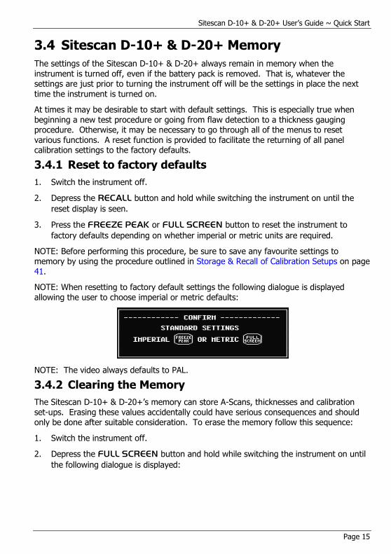
NOTE: When resetting to factory default settings the following dialogue is displayed allowing the user to choose imperial or metric defaults:
NOTE: The video always defaults to PAL.
3.4.2 Clearing the Memory
The Sitescan D-10+ & D-20+’s memory can store A-Scans, thicknesses and calibration set-ups. Erasing these values accidentally could have serious consequences and should only be done after suitable consideration. To erase the memory follow this sequence:
1. Switch the instrument off.
2. Depress the FULL SCREEN button and hold while switching the instrument on until
the following dialogue is displayed:
Sitescan D-10+ & D-20+ User’s Guide ~Quick Start
Page 16
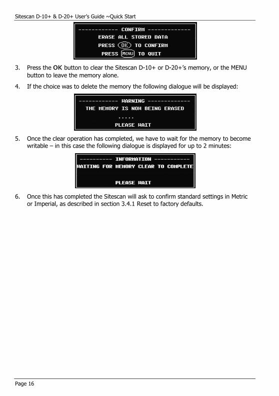
3. Press the OK button to clear the Sitescan D-10+ or D-20+’s memory, or the MENU
button to leave the memory alone.
4. If the choice was to delete the memory the following dialogue will be displayed:
5. Once the clear operation has completed, we have to wait for the memory to become writable – in this case the following dialogue is displayed for up to 2 minutes:
6. Once this has completed the Sitescan will ask to confirm standard settings in Metric or Imperial, as described in section 3.4.1 Reset to factory defaults.
Sitescan D-10+ & D-20+ User’s Guide ~ Detailed Menu Description
Page 17
4 Detailed Menu Description Before proceeding with this section, the user should be familiar with the front panel controls described in section 3.1 Front Panel on page 7. It is also assumed that the user has a good understanding of the theory and practice of ultrasonic testing.
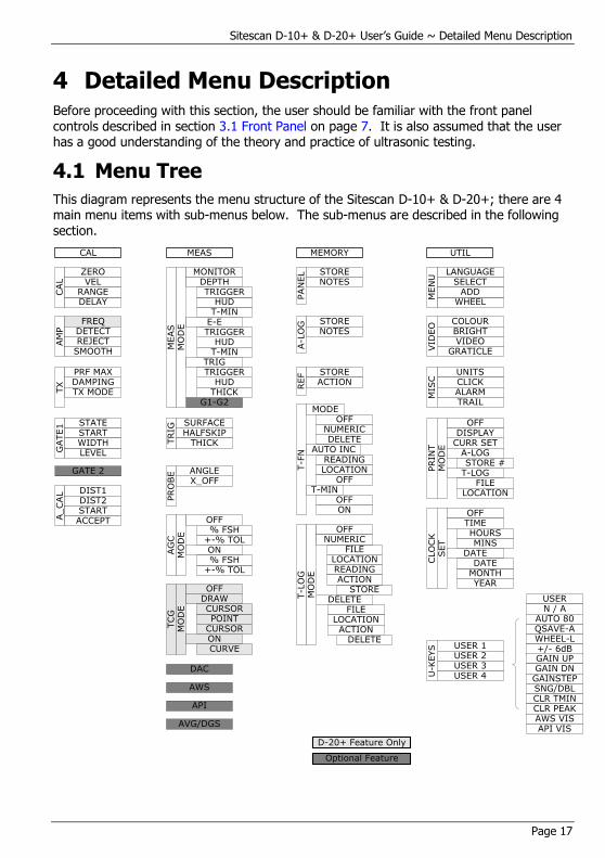
4.1 Menu Tree
This diagram represents the menu structure of the Sitescan D-10+ & D-20+; there are 4 main menu items with sub-menus below. The sub-menus are described in the following section.
CAL MEAS UTILMEMORY
GATE1 STATE
START
LEVELWIDTH
GATE 2
CAL
ZEROVEL
DELAYRANGE
TRIG HALFSKIP
SURFACE
THICK
CLO
CK
SET
OFFTIME
MINSHOURS
DATE
MONTHDATE
YEAR
AG
CM
OD
E
OFF
+-% TOL% FSH
ON
+-% TOL% FSH
PRO
BE
X_OFFANGLE
DAC
A_CAL DIST1
DIST2STARTACCEPT
AVG/DGS
AWS
API
PAN
EL STORE
NOTES
A-L
OG STORE
NOTES
AM
P
FREQDETECT
SMOOTHREJECT
TX DAMPING
PRF MAX
TX MODE
MEAS
MO
DE
DEPTH
TRIG
E-E
G1-G2
HUDTRIGGER
T-MINHUD
TRIGGER
HUDTRIGGER
THICK
T-MIN
MONITOR
TCG
MO
DE
DRAW
POINTCURSOR
OFF
ONCURVE
CURSOR
REF STORE
ACTION
T-F
N
DELETE
MODEOFF
NUMERIC
READINGLOCATION
AUTO INC
OFFT-MIN
OFFON
T-L
OG
FILELOCATION
DELETE
READING
MO
DE
OFFNUMERIC
FILELOCATIONACTION
STOREACTION
DELETE
VID
EO
COLOURBRIGHT
GRATICLEVIDEO
UNITSCLICKALARMM
ISC
PRIN
TM
OD
E
OFF
CURR SETDISPLAY
A-LOG
T-LOGFILE
LOCATION
STORE #
WHEEL
LANGUAGESELECT
ADD
MEN
U
Optional Feature
D-20+ Feature Only
U-K
EYS USER 1
USER 2USER 3USER 4
USERN / A
QSAVE-AAUTO 80
WHEEL-L+/- 6dBGAIN UPGAIN DNGAINSTEPSNG/DBLCLR TMINCLR PEAKAWS VISAPI VIS
TRAIL
Sitescan D-10+ & D-20+User’s Guide ~ Detailed Menu Description
Page 18
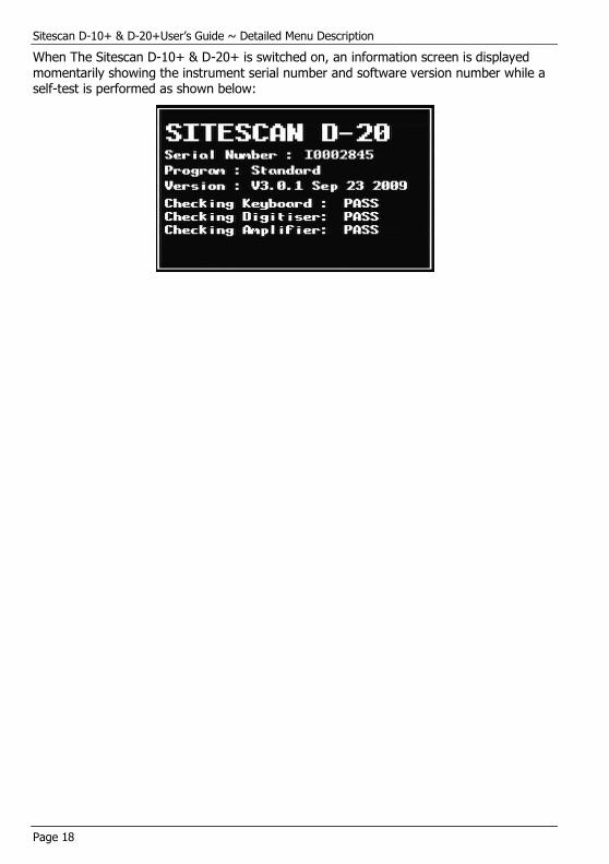
When The Sitescan D-10+ & D-20+ is switched on, an information screen is displayed momentarily showing the instrument serial number and software version number while a self-test is performed as shown below:
Sitescan D-10+ & D-20+ User’s Guide ~ Detailed Menu Description
Page 19
4.2 Main Menu
After the information screen disappears the main menu selections are shown on the right
hand side of the screen. To select a particular menu use the and keys. You can
return to the main menu selection at any time by pressing the MENU button.
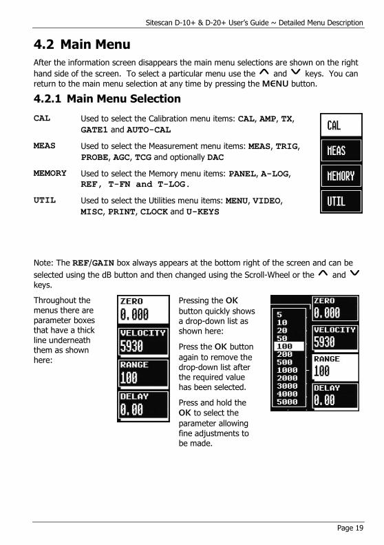
4.2.1 Main Menu Selection
CAL Used to select the Calibration menu items: CAL, AMP, TX,
GATE1 and AUTO-CAL
MEAS Used to select the Measurement menu items: MEAS, TRIG,
PROBE, AGC, TCG and optionally DAC
MEMORY Used to select the Memory menu items: PANEL, A-LOG,
REF, T-FN and T-LOG.
UTIL Used to select the Utilities menu items: MENU, VIDEO,
MISC, PRINT, CLOCK and U-KEYS
Note: The REF/GAIN box always appears at the bottom right of the screen and can be
selected using the dB button and then changed using the Scroll-Wheel or the and keys.
Throughout the
menus there are parameter boxes that have a thick line underneath them as shown here:
Pressing the OK
button quickly shows a drop-down list as shown here:
Press the OK button
again to remove the drop-down list after the required value has been selected.
Press and hold the
OK to select the
parameter allowing
fine adjustments to be made.
Sitescan D-10+ & D-20+User’s Guide ~ Detailed Menu Description
Page 20
4.3 CAL Menu
The CAL menu is the most used menu and contains those items that allow the Sitescan D-10+ & D-20+ to be easily calibrated. For full instruction on how to perform a calibration see Flaw Testing Calibration on page 48
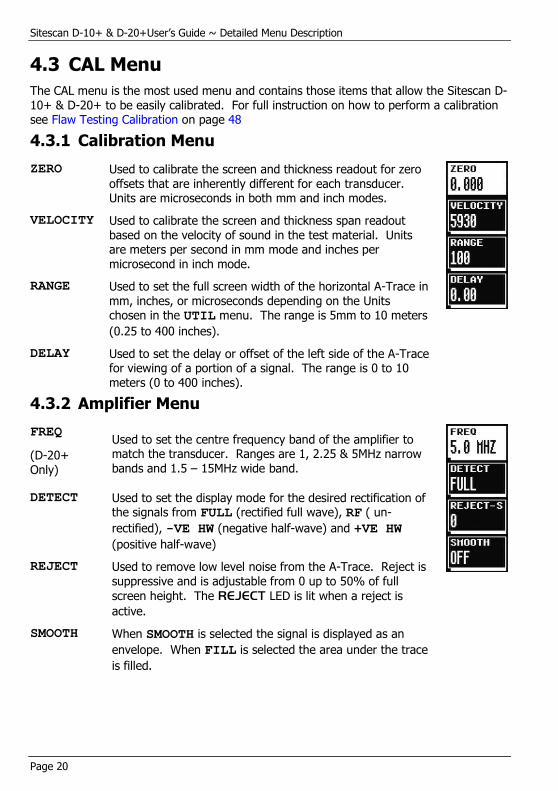
4.3.1 Calibration Menu
ZERO Used to calibrate the screen and thickness readout for zero offsets that are inherently different for each transducer. Units are microseconds in both mm and inch modes.
VELOCITY Used to calibrate the screen and thickness span readout based on the velocity of sound in the test material. Units are meters per second in mm mode and inches per
microsecond in inch mode.
RANGE Used to set the full screen width of the horizontal A-Trace in mm, inches, or microseconds depending on the Units chosen in the UTIL menu. The range is 5mm to 10 meters
(0.25 to 400 inches).
DELAY Used to set the delay or offset of the left side of the A-Trace for viewing of a portion of a signal. The range is 0 to 10 meters (0 to 400 inches).
4.3.2 Amplifier Menu
FREQ
(D-20+ Only)
Used to set the centre frequency band of the amplifier to match the transducer. Ranges are 1, 2.25 & 5MHz narrow bands and 1.5 – 15MHz wide band.
DETECT Used to set the display mode for the desired rectification of the signals from FULL (rectified full wave), RF ( un-
rectified), -VE HW (negative half-wave) and +VE HW
(positive half-wave)
REJECT Used to remove low level noise from the A-Trace. Reject is suppressive and is adjustable from 0 up to 50% of full
screen height. The REJECT LED is lit when a reject is
active.
SMOOTH When SMOOTH is selected the signal is displayed as an
envelope. When FILL is selected the area under the trace
is filled.

Sitescan D-10+ & D-20+ User’s Guide ~ Detailed Menu Description
Page 21
4.3.3 TX Menu
PRF MAX Used to set the maximum pulse repetition frequency. Selectable values are from 35 to 1,000 in 5Hz steps. Lower values will reduce ghosting and noise echoes.
DAMPING Used to select either 400 or 50 Ohms. Select the best to
suite the transducer and cable being used
TX MODE Select SINGLE for single crystal transducers and DOUBLE
for twin crystal transducers
4.3.4 GATE1 & GATE2 Menus
There is one gate available in the Sitescan D-10+ & D-20+ as standard with a second gate as an option, when both gates are installed they have slightly different options depending on the gate and the measurement mode chosen. The following describes the available settings for each gate with the differences between the gates stated. The gates can be identified by the fact that gate 1 has the number “1” above the line and gate 2 has the number “2” above it.
STATE Set the state of the gate as follows:
OFF: Switches the gate off.
+VE: The alarm triggers when an echo in the gate
exceeds the threshold level.
-VE: The alarm triggers when an echo in the gate
falls below the threshold level. Usually used to monitor for loss of back wall echo.
EXPAND: Expands the gate width to fill the horizontal
display width. Only applies to gate 1.
START Used to set the start position of the gate .
Units are mm or inches and range is from 0 to the full time base of the horizontal display.
WIDTH Used to set the width of the gate. Units are mm or inches and range is from 0.02mm (0.001 inch), depending on the range selected, to the full time base of the horizontal display.
LEVEL Used to adjust the alarm threshold level, which corresponds to the vertical height on the A-Trace. Adjustable from 0% to 100% full screen height.
Sitescan D-10+ & D-20+User’s Guide ~ Detailed Menu Description
Page 22
BLANK Only available when E-E measurement is selected. This function sets the blanking distance, as a percentage of the total gate width, which is a blind zone after the first echo, after which a second echo can be measured. This helps to eliminate undesired noise in the first echo from being measured, as thickness but will limit the minimum thickness capability if set too large
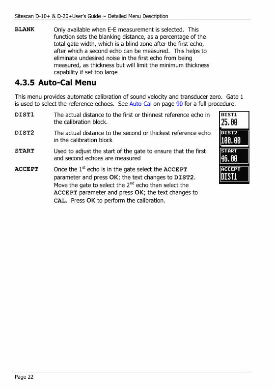
4.3.5 Auto-Cal Menu
This menu provides automatic calibration of sound velocity and transducer zero. Gate 1 is used to select the reference echoes. See Auto-Cal on page 90 for a full procedure.
DIST1 The actual distance to the first or thinnest reference echo in the calibration block.
DIST2 The actual distance to the second or thickest reference echo in the calibration block
START Used to adjust the start of the gate to ensure that the first and second echoes are measured
ACCEPT Once the 1st echo is in the gate select the ACCEPT
parameter and press OK; the text changes to DIST2.
Move the gate to select the 2nd echo than select the
ACCEPT parameter and press OK; the text changes to
CAL. Press OK to perform the calibration.

Sitescan D-10+ & D-20+ User’s Guide ~ Detailed Menu Description
Page 23
4.4 MEAS Menu
The menus in this section allow the various measurement techniques to be configured; these include the general measurement set-up and specialist methods such as AGC, TCG
and DAC. Select the MEAS menu at any time by pressing the MENU button.
4.4.1 Measurement Menu
In the measurement menu, the top selection box shows the selected measurement mode and the remaining three selection boxes vary depending on the mode selected as follows:
MODE:
MONITOR In this mode, gates 1 & 2 act as independent monitor gates
MODE:
DEPTH
In this mode, gate 1 functions as a depth or thickness monitor and displays the depth (D:) and height (H:) of the first signal after the start of the gate that reaches or exceeds the gate level threshold. Values are displayed in a highlighted box below the A-Scan.
TRIGGER Used to select the depth or thickness measurement to the FLANK (left edge) of the first echo after the start of the
gate or the PEAK measurement within the gate i.e. the
largest value in the gate.
HUD When turned ON, provides a large, Head-Up Display of the
depth or thickness reading at the top right of the A-Scan.
The button sequences the selections as follows:
DEPTH E-E TRIG
OFF OFF OFF
(Beam Path) (Beam Path) (Beam Path)
HEIGHT (Surface Distance)
(Defect Depth)
HEIGHT
MODE:
E-E
In this mode, gate 1 functions as a thickness monitor and measures the thickness between the first signal in the gate and the second signal in the gate that reaches or exceeds the level threshold. A second bar is shown representing the blanking (see BLANK in GATE2)
MODE:
TRIG
The Trigonometry mode is used with angle beam transducers for weld inspection to calculate the three important measurements based on the echo position: the Beam path distance (:), the Surface distance (:), and the Depth distance (:) from the index point of the
transducer.
Sitescan D-10+ & D-20+User’s Guide ~ Detailed Menu Description
Page 24
MODE:
F-F
Flank to Flank measurement mode provides a more dynamic echo – echo measurement mode.
It is forced into flank mode, detecting the first rising flank that passes through the gate – the TRIGGER menu option
is removed.
When activated gate 2 becomes an automatic gate, used for measuring between repeat echoes. On a correctly calibrated Sitescan gate 2 will automatically position itself over the repeated echo based on the position of gate 1.
It provides a number of options in the gate 2 menu to allow fine adjustment & control over the gate.
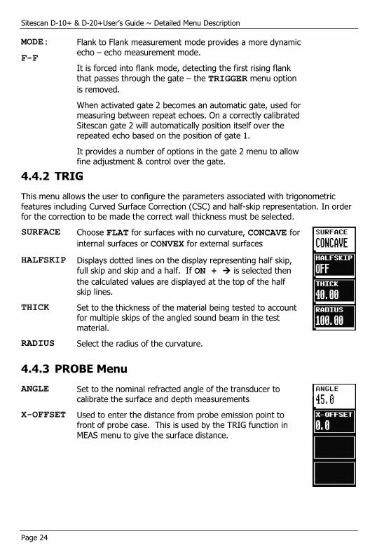
4.4.2 TRIG
This menu allows the user to configure the parameters associated with trigonometric features including Curved Surface Correction (CSC) and half-skip representation. In order for the correction to be made the correct wall thickness must be selected.
SURFACE Choose FLAT for surfaces with no curvature, CONCAVE for
internal surfaces or CONVEX for external surfaces
HALFSKIP Displays dotted lines on the display representing half skip, full skip and skip and a half. If ON + is selected then
the calculated values are displayed at the top of the half skip lines.
THICK Set to the thickness of the material being tested to account for multiple skips of the angled sound beam in the test material.
RADIUS Select the radius of the curvature.
4.4.3 PROBE Menu
ANGLE Set to the nominal refracted angle of the transducer to calibrate the surface and depth measurements
X-OFFSET Used to enter the distance from probe emission point to front of probe case. This is used by the TRIG function in
MEAS menu to give the surface distance.
Sitescan D-10+ & D-20+ User’s Guide ~ Detailed Menu Description
Page 25
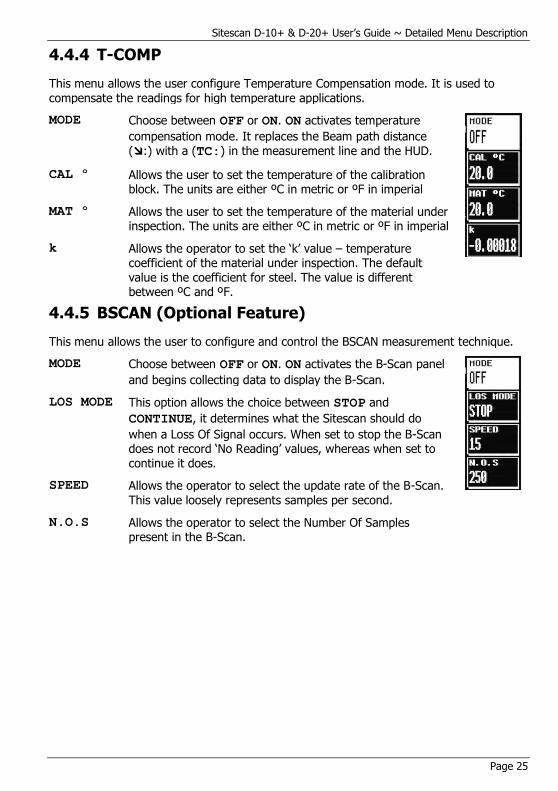
4.4.4 T-COMP
This menu allows the user configure Temperature Compensation mode. It is used to
compensate the readings for high temperature applications.
MODE Choose between OFF or ON. ON activates temperature
compensation mode. It replaces the Beam path distance (:) with a (TC:) in the measurement line and the HUD.
CAL º Allows the user to set the temperature of the calibration block. The units are either ºC in metric or ºF in imperial
MAT º Allows the user to set the temperature of the material under inspection. The units are either ºC in metric or ºF in imperial
k Allows the operator to set the ‘k’ value – temperature coefficient of the material under inspection. The default value is the coefficient for steel. The value is different between ºC and ºF.
4.4.5 BSCAN (Optional Feature)
This menu allows the user to configure and control the BSCAN measurement technique.
MODE Choose between OFF or ON. ON activates the B-Scan panel
and begins collecting data to display the B-Scan.
LOS MODE This option allows the choice between STOP and
CONTINUE, it determines what the Sitescan should do
when a Loss Of Signal occurs. When set to stop the B-Scan does not record ‘No Reading’ values, whereas when set to continue it does.
SPEED Allows the operator to select the update rate of the B-Scan. This value loosely represents samples per second.
N.O.S Allows the operator to select the Number Of Samples present in the B-Scan.
Sitescan D-10+ & D-20+User’s Guide ~ Detailed Menu Description
Page 26
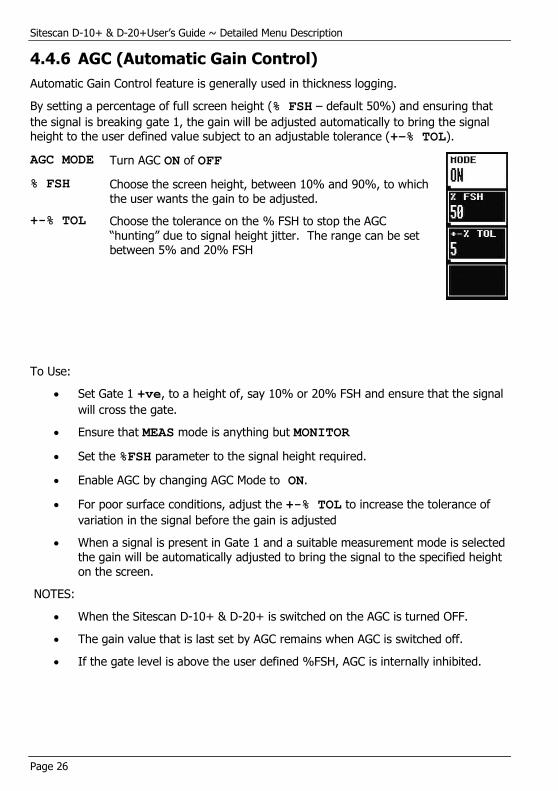
4.4.6 AGC (Automatic Gain Control)
Automatic Gain Control feature is generally used in thickness logging.
By setting a percentage of full screen height (% FSH – default 50%) and ensuring that
the signal is breaking gate 1, the gain will be adjusted automatically to bring the signal height to the user defined value subject to an adjustable tolerance (+–% TOL).
AGC MODE Turn AGC ON of OFF
% FSH Choose the screen height, between 10% and 90%, to which the user wants the gain to be adjusted.
+-% TOL Choose the tolerance on the % FSH to stop the AGC “hunting” due to signal height jitter. The range can be set between 5% and 20% FSH
To Use:
Set Gate 1 +ve, to a height of, say 10% or 20% FSH and ensure that the signal
will cross the gate.
Ensure that MEAS mode is anything but MONITOR
Set the %FSH parameter to the signal height required.
Enable AGC by changing AGC Mode to ON.
For poor surface conditions, adjust the +-% TOL to increase the tolerance of
variation in the signal before the gain is adjusted
When a signal is present in Gate 1 and a suitable measurement mode is selected the gain will be automatically adjusted to bring the signal to the specified height on the screen.
NOTES:
When the Sitescan D-10+ & D-20+ is switched on the AGC is turned OFF.
The gain value that is last set by AGC remains when AGC is switched off.
If the gate level is above the user defined %FSH, AGC is internally inhibited.
Sitescan D-10+ & D-20+ User’s Guide ~ Detailed Menu Description
Page 27
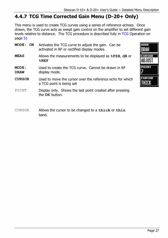
4.4.7 TCG Time Corrected Gain Menu (D-20+ Only)
This menu is used to create TCG curves using a series of reference echoes. Once
drawn, the TCG curve acts as swept gain control on the amplifier to set different gain levels relative to distance. The TCG procedure is described fully in TCG Operation on page 51
MODE: ON Activates the TCG curve to adjust the gain. Can be activated in RF or rectified display modes.
MEAS Allows the measurements to be displayed as %FSH, dB or
%REF
MODE:
DRAW
Used to create the TCG curve. Cannot be drawn in RF display mode.
CURSOR Used to move the cursor over the reference echo for which a TCG point is being set
POINT Display only. Shows the last point created after pressing
the OK button.
CURSOR Allows the cursor to be changed to a thick or thin
band.
Sitescan D-10+ & D-20+User’s Guide ~ Detailed Menu Description
Page 28
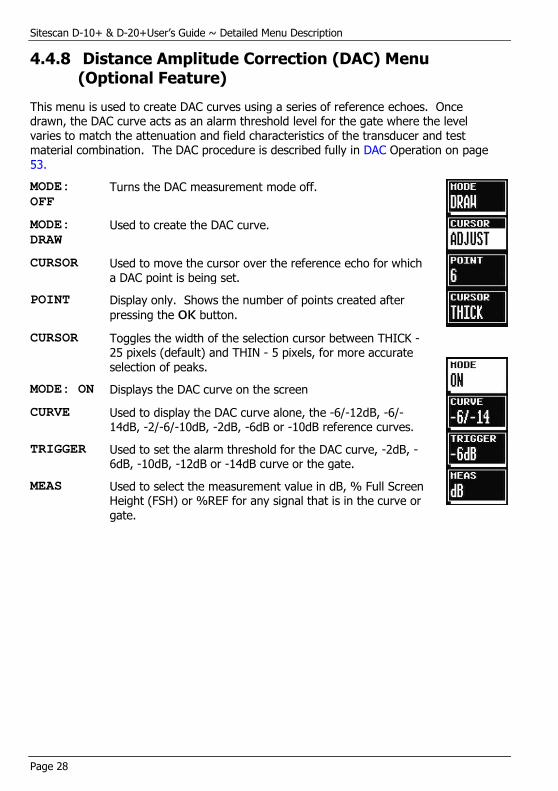
4.4.8 Distance Amplitude Correction (DAC) Menu (Optional Feature)
This menu is used to create DAC curves using a series of reference echoes. Once drawn, the DAC curve acts as an alarm threshold level for the gate where the level varies to match the attenuation and field characteristics of the transducer and test material combination. The DAC procedure is described fully in DAC Operation on page 53.
MODE:
OFF
Turns the DAC measurement mode off.
MODE:
DRAW
Used to create the DAC curve.
CURSOR Used to move the cursor over the reference echo for which a DAC point is being set.
POINT Display only. Shows the number of points created after
pressing the OK button.
CURSOR Toggles the width of the selection cursor between THICK - 25 pixels (default) and THIN - 5 pixels, for more accurate selection of peaks.
MODE: ON Displays the DAC curve on the screen
CURVE Used to display the DAC curve alone, the -6/-12dB, -6/-14dB, -2/-6/-10dB, -2dB, -6dB or -10dB reference curves.
TRIGGER Used to set the alarm threshold for the DAC curve, -2dB, -6dB, -10dB, -12dB or -14dB curve or the gate.
MEAS Used to select the measurement value in dB, % Full Screen Height (FSH) or %REF for any signal that is in the curve or gate.
Sitescan D-10+ & D-20+ User’s Guide ~ Detailed Menu Description
Page 29
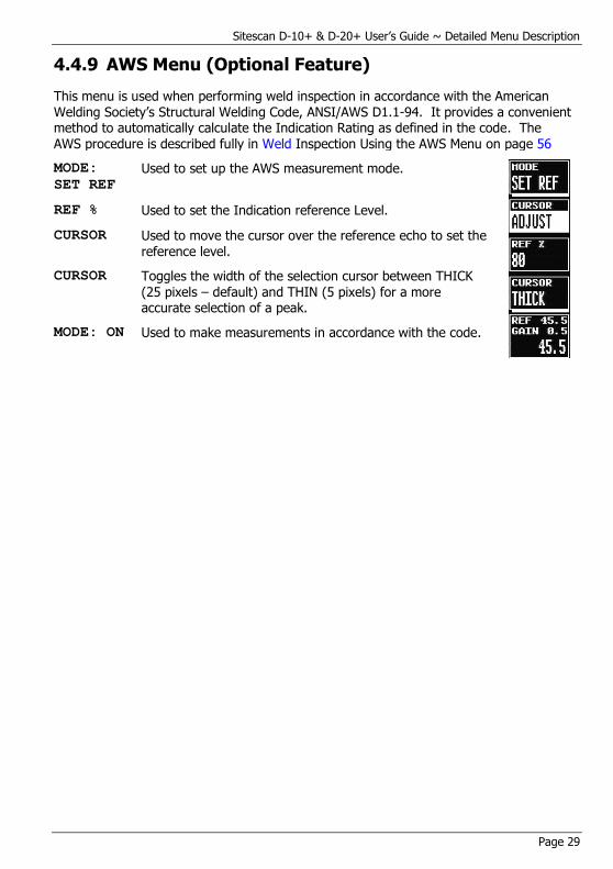
4.4.9 AWS Menu (Optional Feature)
This menu is used when performing weld inspection in accordance with the American Welding Society’s Structural Welding Code, ANSI/AWS D1.1-94. It provides a convenient method to automatically calculate the Indication Rating as defined in the code. The AWS procedure is described fully in Weld Inspection Using the AWS Menu on page 56
MODE:
SET REF
Used to set up the AWS measurement mode.
REF % Used to set the Indication reference Level.
CURSOR Used to move the cursor over the reference echo to set the reference level.
CURSOR Toggles the width of the selection cursor between THICK
(25 pixels – default) and THIN (5 pixels) for a more accurate selection of a peak.
MODE: ON Used to make measurements in accordance with the code.
Sitescan D-10+ & D-20+User’s Guide ~ Detailed Menu Description
Page 30
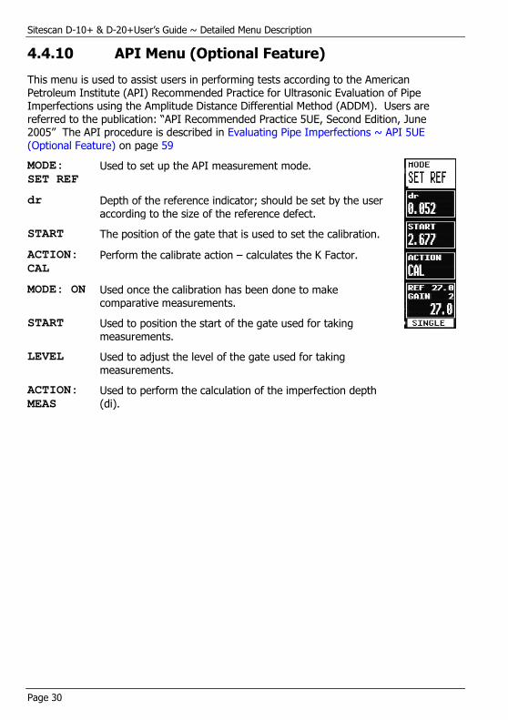
4.4.10 API Menu (Optional Feature)
This menu is used to assist users in performing tests according to the American Petroleum Institute (API) Recommended Practice for Ultrasonic Evaluation of Pipe Imperfections using the Amplitude Distance Differential Method (ADDM). Users are referred to the publication: “API Recommended Practice 5UE, Second Edition, June 2005” The API procedure is described in Evaluating Pipe Imperfections ~ API 5UE (Optional Feature) on page 59
MODE:
SET REF
Used to set up the API measurement mode.
dr Depth of the reference indicator; should be set by the user according to the size of the reference defect.
START The position of the gate that is used to set the calibration.
ACTION:
CAL
Perform the calibrate action – calculates the K Factor.
MODE: ON Used once the calibration has been done to make comparative measurements.
START Used to position the start of the gate used for taking measurements.
LEVEL Used to adjust the level of the gate used for taking measurements.
ACTION:
MEAS
Used to perform the calculation of the imperfection depth
(di).

Sitescan D-10+ & D-20+ User’s Guide ~ Detailed Menu Description
Page 31
4.4.11 DGS/AVG (Optional Feature)
This menu is used to create a DGS/AVG curve that allows flaw sizing and distance compensation without requiring the reference standards that would be required for establishing a DAC curve or to set up a TCG correction. The DGS/AVG procedure is described fully in DGS/AVG Operation on page 62.
MODE:
OFF
Initial mode. Turns off the display of the DGS/AVG curve
FREQ Used to set the transducer frequency taken from its datasheet.
TBVEL Used to set the reference (test) block velocity in m/s
ERS Used to set the Equivalent Reflector Size.
MODE:
SET PRB
Mode used to define curvature correction and probe delay
NFL Used to set the Near Field Length taken from the transducer datasheet
DELAY Used to set the probe delay material velocity in m/s and is used in conjunction with the probe zero and specimen velocity to calculate the sound field equivalent length.
PED This parameter is internally calculated and represents the probe effective diameter. It is not manually adjustable.
MODE:
SET ATT
Used to set attenuation parameters
T-LOSS Used to set the transfer loss in dB due to surface condition, poor coupling etc…
REF dB/m Used to set the reference material attenuation in dB/m
MAT dB/m Used to set the test material attenuation in dB/m
MODE:
SET REF
Used to define the various reference values
dVK Used to set the curvature correction factor in dB and is taken from the transducer datasheet.
REF TYPE Used to select the reference reflector type: Flat Bottom Hole (FBH), Side Drilled Hole (SDH) or Back Wall Echo (BWE)
REFSIZ Used to define the size of the reference type. If REF
TYPE is set to BWE, REFSIZE is set to INFINITE
MODE:
SET SIG
Mode used to perform calibration

Sitescan D-10+ & D-20+User’s Guide ~ Detailed Menu Description
Page 32
CURSOR Select than use the and keys to move the selection over the echo and press OK. The Sitescan 150 will calculate
the sensitivity and draw the curve on the screen
CURSOR Toggles the width of the selection cursor between THICK - 25 pixels (default) and THIN - 5 pixels, for more accurate selection of peaks.
MODE: ON Mode in which DGS/AVG is on.
TRIGGER Used to select either the GATE or the CURVE as the
measurement reference
ERS Used to set the Equivalent Reflector Size.
T-LOSS Used to set the transfer loss in dB due to surface condition, poor coupling etc…

Sitescan D-10+ & D-20+ User’s Guide ~ Detailed Menu Description
Page 33
4.5 MEMORY Menu
Press the MENU button then use the and to select the MEMORY option. These
menus allow the user to save panel settings, A-Scans and thicknesses as well as recalling an A-Scan to be used as a reference.
4.5.1 PANEL Memory Menu
This menu provides storage and recall of up to 100 calibration settings. The use of this feature is described fully in Storage & Recall of Calibration Setups on page 41
STORE # Used to display the list of 100 stores and the status of each – either empty or used; if the store is used the notes label is displayed with the date and time that the panel was stored. The area at the bottom of the window shows the controls for deleting, storing and recalling the panel:
NOTES Shows the notes associated with the stored calibration set.
The bottom of the window shows the controls used to navigate around the notes and to make changes:
(See Adding NOTES to PANEL, A-LOG on page 43. for more details)
Sitescan D-10+ & D-20+User’s Guide ~ Detailed Menu Description
Page 34
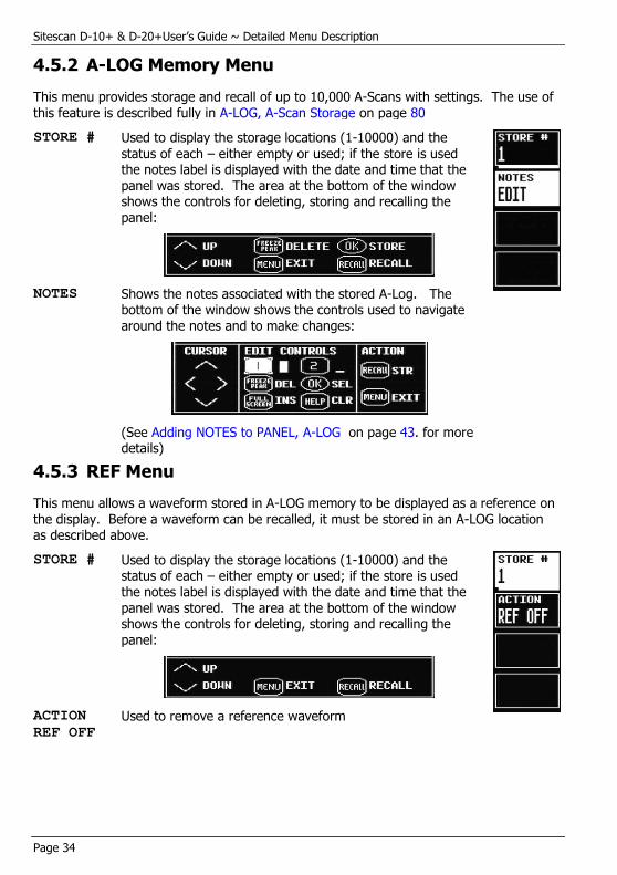
4.5.2 A-LOG Memory Menu
This menu provides storage and recall of up to 10,000 A-Scans with settings. The use of this feature is described fully in A-LOG, A-Scan Storage on page 80
STORE # Used to display the storage locations (1-10000) and the status of each – either empty or used; if the store is used the notes label is displayed with the date and time that the panel was stored. The area at the bottom of the window shows the controls for deleting, storing and recalling the panel:
NOTES Shows the notes associated with the stored A-Log. The bottom of the window shows the controls used to navigate around the notes and to make changes:
(See Adding NOTES to PANEL, A-LOG on page 43. for more details)
4.5.3 REF Menu
This menu allows a waveform stored in A-LOG memory to be displayed as a reference on the display. Before a waveform can be recalled, it must be stored in an A-LOG location as described above.
STORE # Used to display the storage locations (1-10000) and the status of each – either empty or used; if the store is used the notes label is displayed with the date and time that the panel was stored. The area at the bottom of the window shows the controls for deleting, storing and recalling the panel:
ACTION
REF OFF
Used to remove a reference waveform

Sitescan D-10+ & D-20+ User’s Guide ~ Detailed Menu Description
Page 35
4.5.4 B-LOG Memory Menu
This menu provides storage and recall of up to 100 B-Scans with settings. The use of this feature is described fully in B-Log, B-Scan Storage.
STORE # Used to display the storage locations (1-100) and the status of each – either empty or used; if the store is used the notes label is displayed with the date and time that the B-Scan was stored. The area at the bottom of the window shows the controls for deleting, storing and recalling the panel:
Note: The store option is only available in the BSCAN:
MODE is set to ON.
NOTES Shows the notes associated with the stored B-Log. The bottom of the window shows the controls used to navigate around the notes and to make changes:
(See Adding NOTES to PANEL, A-LOG on page 43. for more details)
Sitescan D-10+ & D-20+User’s Guide ~ Detailed Menu Description
Page 36
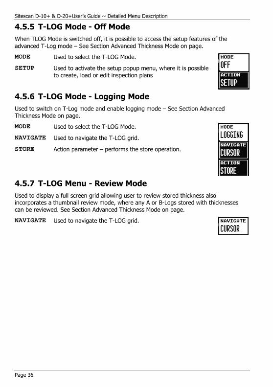
4.5.5 T-LOG Mode - Off Mode
When TLOG Mode is switched off, it is possible to access the setup features of the
advanced T-Log mode – See Section Advanced Thickness Mode on page.
MODE Used to select the T-LOG Mode.
SETUP Used to activate the setup popup menu, where it is possible to create, load or edit inspection plans
4.5.6 T-LOG Mode - Logging Mode
Used to switch on T-Log mode and enable logging mode – See Section Advanced Thickness Mode on page.
MODE Used to select the T-LOG Mode.
NAVIGATE Used to navigate the T-LOG grid.
STORE Action parameter – performs the store operation.
4.5.7 T-LOG Menu - Review Mode
Used to display a full screen grid allowing user to review stored thickness also incorporates a thumbnail review mode, where any A or B-Logs stored with thicknesses can be reviewed. See Section Advanced Thickness Mode on page.
NAVIGATE Used to navigate the T-LOG grid.
Sitescan D-10+ & D-20+ User’s Guide ~ Detailed Menu Description
Page 37
4.6 UTIL Menu
Press the MENU button then use the and to select UTIL to display these menu
options. The items in this section allow the user to configure features such as units, display preferences, language, print options, date and time settings and to assign functions to the user keys
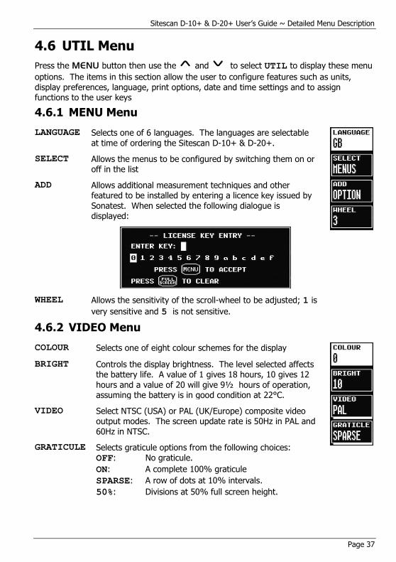
4.6.1 MENU Menu
LANGUAGE Selects one of 6 languages. The languages are selectable at time of ordering the Sitescan D-10+ & D-20+.
SELECT Allows the menus to be configured by switching them on or off in the list
ADD Allows additional measurement techniques and other featured to be installed by entering a licence key issued by Sonatest. When selected the following dialogue is displayed:
WHEEL Allows the sensitivity of the scroll-wheel to be adjusted; 1 is
very sensitive and 5 is not sensitive.
4.6.2 VIDEO Menu
COLOUR Selects one of eight colour schemes for the display
BRIGHT Controls the display brightness. The level selected affects the battery life. A value of 1 gives 18 hours, 10 gives 12 hours and a value of 20 will give 9½ hours of operation, assuming the battery is in good condition at 22°C.
VIDEO Select NTSC (USA) or PAL (UK/Europe) composite video output modes. The screen update rate is 50Hz in PAL and 60Hz in NTSC.
GRATICULE Selects graticule options from the following choices: OFF: No graticule.
ON: A complete 100% graticule
SPARSE: A row of dots at 10% intervals.
50%: Divisions at 50% full screen height.

Sitescan D-10+ & D-20+User’s Guide ~ Detailed Menu Description
Page 38
4.6.3 MISC Menu
UNITS Selects INCHES, or METRIC measurement units.
CLICK Can be set to the following actions:
OFF No click
KEYS Click when a key is pressed
WHEEL Click when the Scroll-Wheel is used
BOTH Click when either the keys or Scroll-Wheel is
used
ALARM Can be set to the following actions:
MUTE No sound when an alarm signal is generated
AUDIBLE Sounds the internal buzzer if an alarm signal is
generated.
4.6.4 PRINT Menu
This menu allows printing of information to a suitable USB printer connected to the USB port on the Sitescan D-10+ & D-20+. Please note that this requires a printer with a USB port from the Sonatest certified list of printers.
OFF The print mode is switched OFF
DISPLAY With the print mode in DISPLAY, the screen display will be
sent to the printer when the OK button is pressed.
CURR SET With the print mode in CURR SET, the current calibration
settings, the screen and all notes are sent to the printer
when the OK button is pressed.
A-LOG In the A-Log print mode, all of the stored A-Scans that are
valid will be printed when the OK button is pressed, along
with the calibration settings and notes. This can take considerable time if the A-Scans memory is full.

Sitescan D-10+ & D-20+ User’s Guide ~ Detailed Menu Description
Page 39
4.6.5 CLOCK Menu
SET OFF Do not display the time at the bottom of the display
SET TIME Used to set the current time.
HOURS Used to set the current hour in 24 hour format
MINS Used to set the current minutes.
SET DATE Used to set the current date.(Selected by pressing the plain
grey button next to SET , then )
DATE Used to set the current day.
MONTH Used to set the current month.
YEAR Used to set the current year.
4.6.6 U-KEYS Menu
This menu allows the user to allocate actions to each of the 4 user keys. These actions are in addition being able to select any menu item and then pressing the required user key for a couple of seconds to allocate that menu item to the key.
Each user button can be assigned to one of the following actions:
PANEL The button has been assigned to a panel – pressing the
button for a short time recalls the panel, pressing for a longer time stores the panel.
USER The button has been defined by the user
N/A Not allocated
AUTO 80 Increases the signal crossing the gate to 80%
QSAVE-A Performs a quick save of the current A-Log
WHEEL-L Locks the Scroll-Wheel
+/- 6dB 1st click increases the gain by 6dB the second click
reduces the gain by 6dB
GAIN UP Increments the gain by the gain step
GAIN DN Reduces the gain by the gain step
GAINSTEP Scrolls through the available gain steps
SNG/DBL Switches between single and double transducers
CLR TMIN Clears the T-MIN if set
CLR PEAK Clears the peak wave form
AWS VIS Shows the HUD when in AWS mode
API VIS Shows the HUD when in API mode
BSCAN ON Toggles B-Scan panel on and off
Sitescan D-10+ & D-20+User’s Guide ~ Detailed Menu Description
Page 40
CLR BSCAN Clears the B-Scan
A-ZERO When T-COMP is active performs an auto probe zero
QSAVE-B Performs a quick save of the current B-Log
Sitescan D-10+ & D-20+ User’s Guide ~ Detailed Menu Description
Page 41
4.7 Storage & Recall of Calibration Setups
After the Sitescan D-10+ & D-20+ has been properly calibrated for a particular testing scheme, it is possible to store all of the panel settings for subsequent recall when performing the same test at a later time. Although the last panel settings are “remembered” by the Sitescan D-10+ & D-20+’s memory, this feature is useful when the instrument is being used for many different tests requiring substantially different panel calibration settings. In addition to the panel settings, a freeform note can be stored with the panel set that includes provision for a label, an operator name or number, a location identifier, and a transducer identifier. It is possible to store up to 100 sets of panel settings; each assigned a set number from 1 to 100. A set of panel settings can be printed after the set is recalled to active memory by using the LIST CPY function in the PRINT menu.
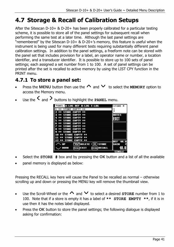
4.7.1 To store a panel set:
Press the MENU button then use the and to select the MEMORY option to
access the Memory menu.
Use the and buttons to highlight the PANEL menu.
Select the STORE # box and by pressing the OK button and a list of all the available
panel memory is displayed as below:
Pressing the RECALL key here will cause the Panel to be recalled as normal – otherwise scrolling up and down or pressing the MENU key will remove the thumbnail view.
Use the Scroll-Wheel or the and to select a desired STORE number from 1 to
100. Note that if a store is empty it has a label of ** STORE EMPTY **, if it is in
use then it has the notes label displayed.
Press the OK button to store the panel settings; the following dialogue is displayed
asking for confirmation:
Sitescan D-10+ & D-20+User’s Guide ~ Detailed Menu Description
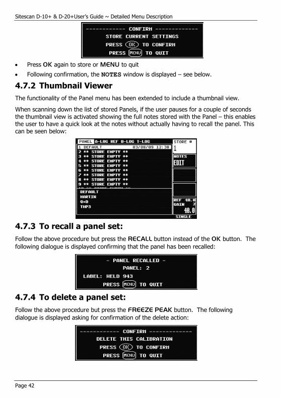
Page 42
Press OK again to store or MENU to quit
Following confirmation, the NOTES window is displayed – see below.
4.7.2 Thumbnail Viewer
The functionality of the Panel menu has been extended to include a thumbnail view.
When scanning down the list of stored Panels, if the user pauses for a couple of seconds the thumbnail view is activated showing the full notes stored with the Panel – this enables the user to have a quick look at the notes without actually having to recall the panel. This can be seen below:
4.7.3 To recall a panel set:
Follow the above procedure but press the RECALL button instead of the OK button. The
following dialogue is displayed confirming that the panel has been recalled:
4.7.4 To delete a panel set:
Follow the above procedure but press the FREEZE PEAK button. The following
dialogue is displayed asking for confirmation of the delete action:
Sitescan D-10+ & D-20+ User’s Guide ~ Detailed Menu Description
Page 43
4.7.5 Adding NOTES to PANEL, A-LOG and B-LOG sets
When storing panel calibration settings or waveforms, it is often useful to add some notes
to the set so it can later be identified, or to help the user recall the correct set. This is possible in the PANEL, A-LOG and B-LOG menus by using the EDIT NOTES feature.
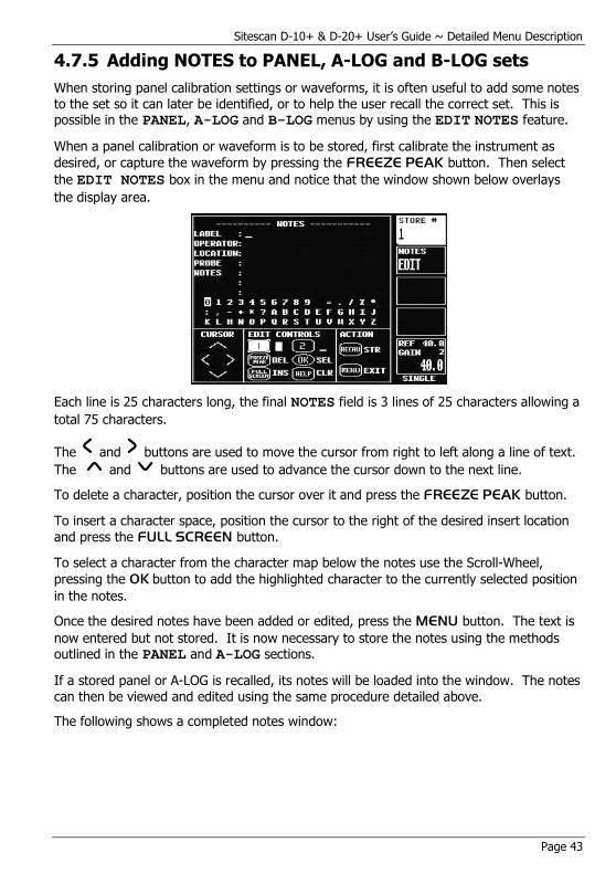
When a panel calibration or waveform is to be stored, first calibrate the instrument as
desired, or capture the waveform by pressing the FREEZE PEAK button. Then select
the EDIT NOTES box in the menu and notice that the window shown below overlays
the display area.
Each line is 25 characters long, the final NOTES field is 3 lines of 25 characters allowing a
total 75 characters.
The and buttons are used to move the cursor from right to left along a line of text.
The and buttons are used to advance the cursor down to the next line.
To delete a character, position the cursor over it and press the FREEZE PEAK button.
To insert a character space, position the cursor to the right of the desired insert location
and press the FULL SCREEN button.
To select a character from the character map below the notes use the Scroll-Wheel,
pressing the OK button to add the highlighted character to the currently selected position
in the notes.
Once the desired notes have been added or edited, press the MENU button. The text is
now entered but not stored. It is now necessary to store the notes using the methods outlined in the PANEL and A-LOG sections.
If a stored panel or A-LOG is recalled, its notes will be loaded into the window. The notes
can then be viewed and edited using the same procedure detailed above.
The following shows a completed notes window:

Sitescan D-10+ & D-20+User’s Guide ~ Detailed Menu Description
Page 44
4.7.6 Using the Optional Keyboard
The Sitescan D-10+ & D-20+ support a standard 102 – 104 key USB keyboard. A Sonatest USB adapter lead is required to connect the keyboard. The British keyboard
layout is used.
The external keyboard can be used to fully control the Sitescan D-10+ & D-20+ using the arrow keys, enter and escape to navigate the menus. The function keys (F1 – F12) provide a method to activate certain features.
Pressing enter on a parameter that has a popup box associated with it will activate the popup box, pressing shift + enter together will select the parameter for free adjustment using the arrow keys.
It is possible to use the keyboard to type in new values (using the Insert key) for numeric parameters, rather than use the arrows to increment and decrement – in this operation the Sitescan pops up an entry panel for the user to input the value, if the value is accepted the new value will appear in the parameter box, if an incorrect value is entered an error message displayed.
Caps Lock and Num Lock keys operate as expected. The unit will display CAPSL and / or NUM-L in the information line to indicate to the user that it is active. The keyboard driver is unable to activate any of the LED’s that may be present on the keyboard.
It is also possible to use the keyboard normally to type notes into the notes pages. The shift keys are available to obtain capital letters (when caps lock is switched off)
Sitescan D-10+ & D-20+ User’s Guide ~ Detailed Menu Description
Page 45
External Keyboard Key-press Action
Escape Same operation as the front panel Menu Key
Arrow Keys (incl. Num-pad Arrows)
Same operation as the front panel D-Pad
F1 – F4 Quick access to right hand menu bar, F1 = Top menu / parameter, F4 = Bottom menu / parameter
F5 Same as front panel Help Key
F6 Same as front panel Recall Key
F7 Same as front panel Freeze / Peak Key
F8 Same as front panel Full Screen Key
F9 – F12 Same as user keys, F9 = User 1, F12 = User 4
D / d Same as front panel dB key
F / f Same as front panel Freeze / Peak Key
G / g Same as front panel Gate Key
H / h Same as front panel Help Key
R / r Same as front panel Recall Key
S / s Single / Double (toggles TX Mode)
X / x Gain Step function – (increments gain step value)
Page Up Adjust Gain Up
Page Down Adjust Gain Down
Enter (incl. Num-pad Enter) Same as front panel OK key
Shift+Enter (incl. Num-pad Enter) Same as press & hold front panel OK key
Insert Allows free entry of numeric parameters.
Backspace Operates as Menu Key.
4.7.7 Entering License Key to Activate Options
The Sitescan software contains the optional features as standard but require a license key in order to enable them.
License keys can be obtained for the (paid for) optional features by contacting your local distributor.
The MENU menu can be found under the UTIL menu. Pressing the OK button on the ADD: OPTION parameter will activate the license key entry panel as shown below:

Sitescan D-10+ & D-20+User’s Guide ~ Detailed Menu Description
Page 46
Use the scroll wheel to select characters from the key map, pressing the OK key to add to the currently selected character to the license key entry field.
The user key 1 and user key 2 toggle the navigation mode, 1 is used to navigate they key map and 2 is used to navigate the entry field. The highlight indicates which is currently active.
Pressing the HELP key will clear all characters and return the cursor to the beginning of the field. The FREEZE / PEAK key will delete the character currently under the cursor and the FULL SCREEN key will insert a space at the currently selected position.
Pressing the MENU key when complete will exit the license key entry panel displaying a confirmation message whether the license key was accepted or not. If the license key is accepted the Sitescan will return the main menu and the new option will be available in
the menu system.
The bottom section of the license key entry panel shows the options that are currently enabled.
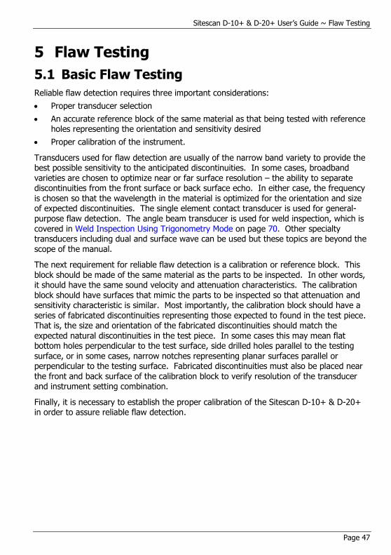
Sitescan D-10+ & D-20+ User’s Guide ~ Flaw Testing
Page 47
5 Flaw Testing
5.1 Basic Flaw Testing
Reliable flaw detection requires three important considerations:
Proper transducer selection
An accurate reference block of the same material as that being tested with reference holes representing the orientation and sensitivity desired
Proper calibration of the instrument.
Transducers used for flaw detection are usually of the narrow band variety to provide the best possible sensitivity to the anticipated discontinuities. In some cases, broadband varieties are chosen to optimize near or far surface resolution – the ability to separate discontinuities from the front surface or back surface echo. In either case, the frequency is chosen so that the wavelength in the material is optimized for the orientation and size of expected discontinuities. The single element contact transducer is used for general-purpose flaw detection. The angle beam transducer is used for weld inspection, which is covered in Weld Inspection Using Trigonometry Mode on page 70. Other specialty transducers including dual and surface wave can be used but these topics are beyond the scope of the manual.
The next requirement for reliable flaw detection is a calibration or reference block. This block should be made of the same material as the parts to be inspected. In other words, it should have the same sound velocity and attenuation characteristics. The calibration block should have surfaces that mimic the parts to be inspected so that attenuation and sensitivity characteristic is similar. Most importantly, the calibration block should have a
series of fabricated discontinuities representing those expected to found in the test piece. That is, the size and orientation of the fabricated discontinuities should match the expected natural discontinuities in the test piece. In some cases this may mean flat bottom holes perpendicular to the test surface, side drilled holes parallel to the testing surface, or in some cases, narrow notches representing planar surfaces parallel or perpendicular to the testing surface. Fabricated discontinuities must also be placed near the front and back surface of the calibration block to verify resolution of the transducer and instrument setting combination.
Finally, it is necessary to establish the proper calibration of the Sitescan D-10+ & D-20+ in order to assure reliable flaw detection.
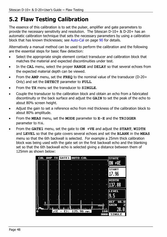
Sitescan D-10+ & D-20+User’s Guide ~ Flaw Testing
Page 48
5.2 Flaw Testing Calibration
The essence of this calibration is to set the pulser, amplifier and gate parameters to provide the necessary sensitivity and resolution. The Sitescan D-10+ & D-20+ has an automatic calibration technique that sets the necessary parameters by using a calibration block that has known thicknesses; see Auto-Cal on page 90 for details.
Alternatively a manual method can be used to perform the calibration and the following are the essential steps for basic flaw detection:
Select the appropriate single element contact transducer and calibration block that matches the material and expected discontinuities under test.
In the CAL menu, select the proper RANGE and DELAY so that several echoes from
the expected material depth can be viewed.
From the AMP menu, set the FREQ to the nominal value of the transducer (D-20+
Only) and set the DETECT parameter to FULL.
From the TX menu set the transducer to SINGLE.
Couple the transducer to the calibration block and obtain an echo from a fabricated discontinuity or the back surface and adjust the GAIN to set the peak of the echo to
about 80% screen height.
Adjust the gain to set a reference echo from mid thickness of the calibration block to about 80% amplitude.
From the MEAS menu, set the MODE parameter to E-E and the TRIGGER
parameter to PEAK.
From the GATE1 menu, set the gate to ON +VE and adjust the START, WIDTH
and LEVEL so that the gate covers several echoes and set the BLANK in the MEAS
menu so that the 6th backwall is selected. For example a 25mm thick calibration block was being used with the gate set on the first backwall echo and the blanking set so that the 6th backwall echo is selected giving a distance between them of 125mm as shown below:
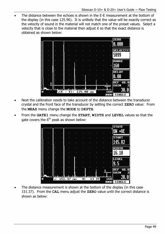
Sitescan D-10+ & D-20+ User’s Guide ~ Flaw Testing
Page 49
The distance between the echoes is shown in the E-E measurement at the bottom of the display (in this case 125.96). It is unlikely that the value will be exactly correct as the velocity of sound in the material will not match one of the preset values. Select a velocity that is close to the material then adjust it so that the exact distance is obtained as shown below:
Next the calibration needs to take account of the distance between the transducer crystal and the front face of the transducer by setting the correct ZERO value: From
the MEAS menu change the MODE to DEPTH.
From the GATE1 menu change the START, WIDTH and LEVEL values so that the
gate covers the 6th peak as shown below:
The distance measurement is shown at the bottom of the display (in this case 151.37). From the CAL menu adjust the ZERO value until the correct distance is
shown as below:
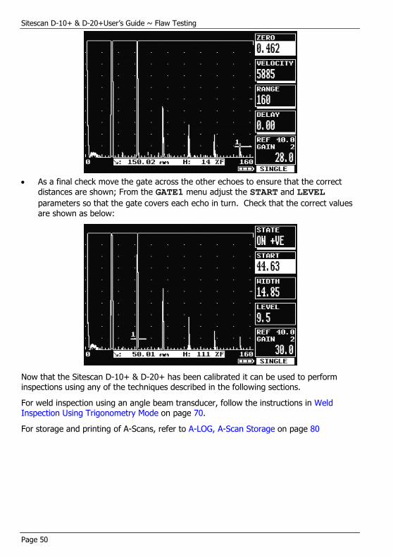
Sitescan D-10+ & D-20+User’s Guide ~ Flaw Testing
Page 50
As a final check move the gate across the other echoes to ensure that the correct
distances are shown; From the GATE1 menu adjust the START and LEVEL
parameters so that the gate covers each echo in turn. Check that the correct values are shown as below:
Now that the Sitescan D-10+ & D-20+ has been calibrated it can be used to perform inspections using any of the techniques described in the following sections.
For weld inspection using an angle beam transducer, follow the instructions in Weld Inspection Using Trigonometry Mode on page 70.
For storage and printing of A-Scans, refer to A-LOG, A-Scan Storage on page 80

Sitescan D-10+ & D-20+ User’s Guide ~ Flaw Testing
Page 51
5.3 TCG Operation (D-20+ Only)
The Time Corrected Gain feature provides a means of creating an attenuation curve that sets the gain in a swept manner as a function of transit time. A properly constructed TCG curve will compensate for material attenuation and sound beam characteristics so that discontinuities of equal relative size at different depths in the test piece will give an equal amplitude response on the display.
Proper use of the TCG feature requires a reference block made from the same material as that being examined, with flat-bottom or side-drilled holes of the desired size placed at depths covering the range to be inspected.
To establish a TCG curve, follow the following instructions:
Establish the basic calibration of the Sitescan D-20+ using the desired transducer and the proper reference block.
From the MEAS menu, select the TCG feature.
Select the MODE parameter by pressing the OK button then use the and
keys to select the select DRAW then press OK again to enter draw mode The other
parameters will now be CURSOR and POINT.
The TCG system is now ready to accept reference points. Position the transducer to give a maximum echo from the first or topmost reference hole in the reference block. Be careful to use a consistent amount of coupling and transducer pressure.
Use the Scroll-Wheel to position the bright cursor bar over the echo from the reference hole.
Press the OK button to accept the point. The POINT parameter will then increment
to indicate the next point. As each point is entered, the gain will change to place the echoes at about 80% amplitude as shown below:
Repeat steps 5 and 6 for each additional reference hole in the reference block, being careful to be consistent with the amount of coupling and transducer pressure. A maximum of 10 points can be recorded for a TCG curve.

Sitescan D-10+ & D-20+User’s Guide ~ Flaw Testing
Page 52
Press MENU to come out of the adjust parameter then use the key to move to
the MODE box, use the OK button to display the drop down list then use the to
select ON mode then OK again to actually turn TCG on.
NOTE: A TCG curve cannot be drawn while in RF display mode. It should be noted that the range of TCG is limited by the dynamic range of 40dB.

Sitescan D-10+ & D-20+ User’s Guide ~ Flaw Testing
Page 53
5.4 DAC Operation (Optional Feature)
Distance Amplitude Correction curves act as monitoring gate triggering thresholds to compensate for attenuation and sound beam characteristics. When properly established, the DAC curve will provide consistent alarming from discontinuities of equal relative size at different depths in the test piece. Functionality is provided to automatically draw 6dB and 14dB or 6dB and 12dB reference curves below the calibrated curve.
It should be noted that since the DAC function only provides a dynamic alarm threshold capability, the dynamic range is limited to about 16dB. Therefore, for materials that attenuate more than 16dB over the depth range of interest, DAC should not be used. Instead, the TCG function may be more applicable. See TCG Operation on page 51 for the use of the Time Corrected Gain feature.
Proper use of the DAC feature requires a reference block made from the same material as
that being examined, with flat-bottom or side-drilled holes of the desired size placed at depths covering the range to be inspected.
To establish a DAC curve, follow these instructions:
Establish the basic calibration of the Sitescan D-10+ & D-20+ using the desired transducer and the proper reference block. From the MEAS menu, select the DAC
feature.
Select the MODE parameter by pressing the OK button then use the and
keys to select the select DRAW then press OK again to enter draw mode The other
parameters will now be CURSOR and POINT.
The DAC system is now ready to accept reference points. Position the transducer to give a maximum echo from the first or topmost reference hole in the reference block.
Be careful to use a consistent amount of coupling and transducer pressure.
Use the Scroll-Wheel to position the bright cursor bar over the echo from the reference hole.
Press the OK button for a minimum of 2 seconds to accept the point. The POINT
parameter will then increment to indicate the next point. A small square will appear as a reference point on the display showing the peak of the signal just recorded.
Repeat steps 4 and 5 for each additional reference hole in the reference block, being careful to be consistent with the amount of coupling and transducer pressure. A maximum of 10 points can be recorded for a DAC curve.
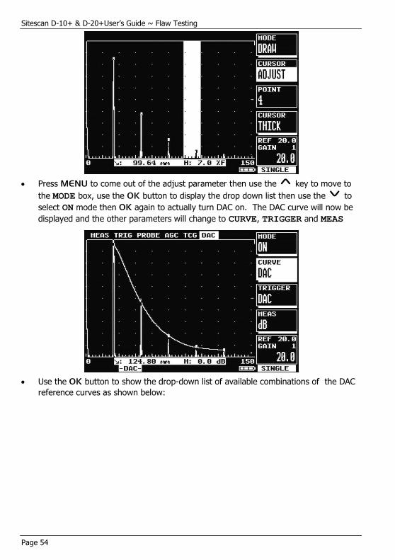
Sitescan D-10+ & D-20+User’s Guide ~ Flaw Testing
Page 54
Press MENU to come out of the adjust parameter then use the key to move to
the MODE box, use the OK button to display the drop down list then use the to
select ON mode then OK again to actually turn DAC on. The DAC curve will now be
displayed and the other parameters will change to CURVE, TRIGGER and MEAS
Use the OK button to show the drop-down list of available combinations of the DAC
reference curves as shown below:

Sitescan D-10+ & D-20+ User’s Guide ~ Flaw Testing
Page 55
These additional, automatically generated, reference curves provide a method for
helping to evaluate discontinuities smaller than those in the reference block.
Use the TRIGGER parameter to select the alarm trigger from Gate 1, the DAC curve,
or any of the additional curves listed in the curve parameter above that are currently selected.
The MEAS parameter allows the measurements to be displayed as %FSH
(percentage of Full Screen Height) dB (as referenced to the DAC curve) or %REF
(percentage of DAC curve)
To turn off the DAC feature, select the MODE parameter from the DAC menu and press
the OK to display the drop-down list then use the and keys the button until OFF
is indicated, finally press OK again to turn DAC off

Sitescan D-10+ & D-20+User’s Guide ~ Flaw Testing
Page 56
5.5 Weld Inspection Using the AWS Menu (Optional Feature)
The AWS menu provides a means for evaluating discontinuities when inspecting welds in accordance with the American Welding Society’s Structural Welding Code, ANSI/AWS D1.1-94. The user is referred to the AWS standard for full details of the method.
The AWS menu provides a convenient method of automatically calculating the “Indication Rating” (IR) as defined by the standard. The AWS menu can be used in conjunction with the trigonometry mode which will simultaneously indicate beam path, surface distance and depth distance at the bottom of the graticule. The AWS menu will not operate with any of DAC, TCG, AVG, API or T-LOG mode switched on.
To set up the AWS measurements, perform the following:
1. Calibrate the Sitescan D-10+ or D-20+ for weld testing and set up the trigonometry mode by following the steps in Weld Inspection Using Trigonometry Mode on page 70.
2. From the MEAS menu, select AWS and place the MODE to SET REF.
3. Highlight REF % on the menu and set to the desired reference level, usually 80% of
full screen height.
4. Place the probe on the test block and obtain the maximum signal from the reference indication.
5. Place the cursor over the indication by selecting CURSOR: ADJUST and using the
scroll-wheel.
6. With the signal maximized, press the OK key whilst the ACTION: CAL parameter
is highlighted.
The Sitescan D-10+ or D-20+ is now calibrated to make Indication Rating measurements in accordance with AWS D1.1-94. To use the AWS mode, do the following:

Sitescan D-10+ & D-20+ User’s Guide ~ Flaw Testing
Page 57
1. On the AWS menu, highlight MODE and select ON. Switching AWS on will enable the
AWS HUD at the top of the display, where the live measurements will be displayed.
2. Ensure that the gate and measurement (TRIG) function are operative and properly
adjusted.
3. When the AWS menu is selected and a signal is in the gate, the HUD will show the
resulting AWS measurements as follows:
AFRGILIR
(Indication Rating = Indication level – Reference Gain – Attenuation Factor)
Where:
IL: Indication Level The dB setting required to bring an indication to the reference level.
RG: Reference Gain The dB setting of the calibrated reference indication as a function of the reference standard and probe being employed.
AF: Attenuation Factor The attenuation factor required by the AWS standard and is: Depth in inches minus 1, multiply by 2 and then rounded to the nearest ½ dB.
IR: Indication Rating The difference in dB between the indication and the reference gain with attenuation factor correction.
It is not necessary to bring the indication to the reference level to obtain the correct measurement information as the Sitescan D-10+ & D-20+ adjusts for gain offset. However, to ensure the best accuracy of calculation, it is advised to adjust the indication to be above 40% and below 100% of full screen height. In addition, in the AWS mode, gain offset is shown as +/- dB from reference as opposed to absolute gain.
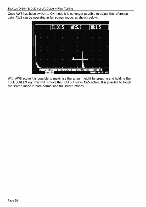
Sitescan D-10+ & D-20+User’s Guide ~ Flaw Testing
Page 58
Once AWS has been switch to ON mode it is no longer possible to adjust the reference gain. AWS can be operated in full screen mode, as shown below:
With AWS active it is possible to maximise the screen height by pressing and holding the FULL SCREEN key, this will remove the HUD but leave AWS active. It is possible to toggle the screen mode in both normal and full screen modes.

Sitescan D-10+ & D-20+ User’s Guide ~ Flaw Testing
Page 59
5.6 Evaluating Pipe Imperfections ~ API 5UE (Optional Feature)
The Sitescan D-10+ & D-20+ is able to assist the user in making measurements in accordance with the American Petroleum Institute (API) Recommended Practice for Ultrasonic Evaluation of Pipe Imperfections using the Amplitude Distance Differential Method (ADDM). Users are referred to the publication: “API Recommended Practice 5UE, Second Edition, June 2005”
The ADDT employs a combination of amplitude comparison and 6dB drop techniques to determine the radial depth of an imperfection. The technique is based on the premise that radial depth of an imperfection affects both the amplitude of the received echo signal and the differential time of flight of the transmitted ultrasonic wave as it passes over the imperfection.
The first step is to perform ‘standardisation’ using a reference indicator such as a notch at a known depth or a through drilled hole. It is assumed that the Sitescan D-10+ or D-20+ has been setup with the correct values for the transducer and specimen under inspection.
First turn on GATE1 from the CAL menu and position it on the display so that it will
cover the signal that will be produced by the reference indicator; the height of the gate is not important. Ensure that the signal will be between 5% and 100% of full screen height. Select API from the MEAS menu and select ACTIVE PEAK MODE by pressing the
button twice then capture the reference signal and the following display should be shown:
Once the desired signal is obtained press the OK button whilst the ACTION: CAL
parameter is highlighted and the K factor (a derived factor for calculating depth) is calculated and displayed as shown:
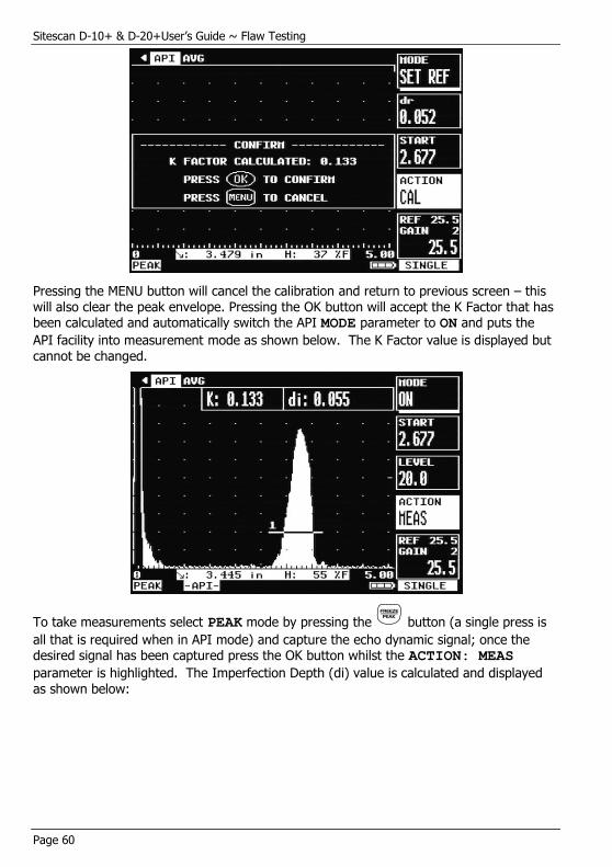
Sitescan D-10+ & D-20+User’s Guide ~ Flaw Testing
Page 60
Pressing the MENU button will cancel the calibration and return to previous screen – this will also clear the peak envelope. Pressing the OK button will accept the K Factor that has been calculated and automatically switch the API MODE parameter to ON and puts the
API facility into measurement mode as shown below. The K Factor value is displayed but cannot be changed.
To take measurements select PEAK mode by pressing the button (a single press is
all that is required when in API mode) and capture the echo dynamic signal; once the desired signal has been captured press the OK button whilst the ACTION: MEAS
parameter is highlighted. The Imperfection Depth (di) value is calculated and displayed
as shown below:
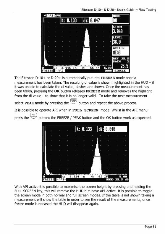
Sitescan D-10+ & D-20+ User’s Guide ~ Flaw Testing
Page 61
The Sitescan D-10+ or D-20+ is automatically put into FREEZE mode once a
measurement has been taken. The resulting di value is shown highlighted in the HUD – if it was unable to calculate the di value, dashes are shown. Once the measurement has
been taken, pressing the OK button releases FREEZE mode and removes the highlight
from the di value – to show that it is no longer valid. To take the next measurement
select PEAK mode by pressing the button and repeat the above process.
It is possible to operate API when in FULL SCREEN mode. Whilst in the API menu
press the button; the FREEZE / PEAK button and the OK button work as expected.
With API active it is possible to maximise the screen height by pressing and holding the FULL SCREEN key, this will remove the HUD but leave API active. It is possible to toggle the screen mode in both normal and full screen modes. If the table is not shown taking a measurement will show the table in order to see the result of the measurements, once freeze mode is released the HUD will disappear again.
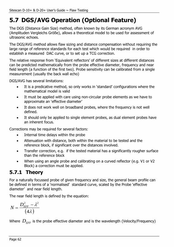
Sitescan D-10+ & D-20+ User’s Guide ~ Flaw Testing
Page 62
5.7 DGS/AVG Operation (Optional Feature)
The DGS (Distance Gain Size) method, often known by its German acronym AVG (Amplituden Vergleichs Größe), allows a theoretical model to be used for assessment of ultrasonic echoes.
The DGS/AVG method allows flaw sizing and distance compensation without requiring the large range of reference standards for each test which would be required in order to establish a measured DAC curve, or to set up a TCG correction.
The relative response from ‘Equivalent reflectors’ of different sizes at different distances can be predicted mathematically from the probe effective diameter, frequency and near field length (a function of the first two). Probe sensitivity can be calibrated from a single measurement (usually the back wall echo)
DGS/AVG has several limitations:
It is a predicative method, so only works in ‘standard’ configurations where the mathematical model is valid
It must be applied with care using non-circular probe elements as we have to approximate an ‘effective diameter’
It does not work well on broadband probes, where the frequency is not well defined.
It should only be applied to single element probes, as dual element probes have an inherent focus.
Corrections may be required for several factors:
Internal time delays within the probe
Attenuation with distance, both within the material to be tested and the reference block, if significant over the distances involved.
Transfer correction, e.g. if the tested material has a significantly rougher surface than the reference block
When using an angle probe and calibrating on a curved reflector (e.g. V1 or V2 Block) a correction must be applied.
5.7.1 Theory
For a naturally focussed probe of given frequency and size, the general beam profile can be defined in terms of a ‘normalised’ standard curve, scaled by the Probe ‘effective diameter’ and near field length.
The near field length is defined by the equation:
4
22 EFFD
N
Where EFFD is the probe effective diameter and is the wavelength (Velocity/Frequency)
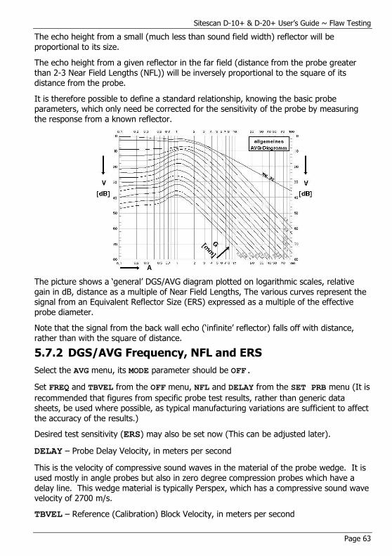
Sitescan D-10+ & D-20+ User’s Guide ~ Flaw Testing
Page 63
The echo height from a small (much less than sound field width) reflector will be proportional to its size.
The echo height from a given reflector in the far field (distance from the probe greater than 2-3 Near Field Lengths (NFL)) will be inversely proportional to the square of its distance from the probe.
It is therefore possible to define a standard relationship, knowing the basic probe parameters, which only need be corrected for the sensitivity of the probe by measuring the response from a known reflector.
The picture shows a ‘general’ DGS/AVG diagram plotted on logarithmic scales, relative gain in dB, distance as a multiple of Near Field Lengths, The various curves represent the signal from an Equivalent Reflector Size (ERS) expressed as a multiple of the effective
probe diameter.
Note that the signal from the back wall echo (‘infinite’ reflector) falls off with distance, rather than with the square of distance.
5.7.2 DGS/AVG Frequency, NFL and ERS
Select the AVG menu, its MODE parameter should be OFF.
Set FREQ and TBVEL from the OFF menu, NFL and DELAY from the SET PRB menu (It is
recommended that figures from specific probe test results, rather than generic data sheets, be used where possible, as typical manufacturing variations are sufficient to affect the accuracy of the results.)
Desired test sensitivity (ERS) may also be set now (This can be adjusted later).
DELAY – Probe Delay Velocity, in meters per second
This is the velocity of compressive sound waves in the material of the probe wedge. It is used mostly in angle probes but also in zero degree compression probes which have a delay line. This wedge material is typically Perspex, which has a compressive sound wave velocity of 2700 m/s.
TBVEL – Reference (Calibration) Block Velocity, in meters per second
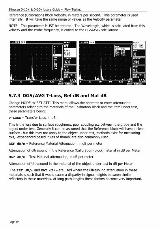
Sitescan D-10+ & D-20+ User’s Guide ~ Flaw Testing
Page 64
Reference (Calibration) Block Velocity, in meters per second. This parameter is used internally. It will take the same range of values as the Velocity parameter.
NOTE: This parameter MUST be entered. The Wavelength, which is calculated from this velocity and the Probe frequency, is critical to the DGS/AVG calculations.
5.7.3 DGS/AVG T-Loss, Ref dB and Mat dB
Change MODE to ‘SET ATT’. This menu allows the operator to enter attenuation parameters relating to the materials of the Calibration Block and the item under test, these parameters being:
T-LOSS – Transfer Loss, in dB.
This is the loss due to surface roughness, poor coupling etc between the probe and the
object under test. Generally it can be assumed that the Reference block will have a clean surface , but this may not apply to the object under test, methods exist for measuring this, experienced based ‘rules of thumb’ are also commonly used.
REF dB/m – Reference Material Attenuation, in dB per meter
Attenuation of ultrasound in the Reference (Calibration) block material in dB per Meter
MAT dB/m – Test Material attenuation, in dB per meter
Attenuation of Ultrasound in the material of the object under test in dB per Meter
The REF dB/m and MAT dB/m are used where the ultrasound attenuation in these
materials is such that it would cause a disparity in signal heights between similar reflectors in these materials. At long path lengths these factors become very important.
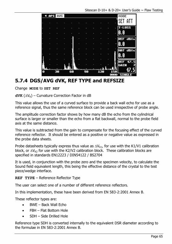
Sitescan D-10+ & D-20+ User’s Guide ~ Flaw Testing
Page 65
5.7.4 DGS/AVG dVK, REF TYPE and REFSIZE
Change MODE to SET REF
dVK (VK) – Curvature Correction Factor in dB
This value allows the use of a curved surface to provide a back wall echo for use as a reference signal, thus the same reference block can be used irrespective of probe angle.
The amplitude correction factor shows by how many dB the echo from the cylindrical surface is larger or smaller than the echo from a flat backwall, normal to the probe field axis at the same distance.
This value is subtracted from the gain to compensate for the focusing effect of the curved reference reflector. It should be entered as a positive or negative value as expressed in the probe data sheets.
Probe datasheets typically express thus value as VK1, for use with the K1/V1 calibration
block, or VK2 for use with the K2/V2 calibration block. These calibration blocks are
specified in standards EN12223 / DIN54122 / BS2704
It is used, in conjunction with the probe zero and the specimen velocity, to calculate the Sound field equivalent length, this being the effective distance of the crystal to the test piece/wedge interface.
REF TYPE – Reference Reflector Type
The user can select one of a number of different reference reflectors.
In this implementation, these have been derived from EN 583-2:2001 Annex B.
These reflector types are:
BWE – Back Wall Echo
FBH – Flat Bottom Hole
SDH – Side Drilled Hole
Reference type SDH is converted internally to the equivalent DSR diameter according to the formulae in EN 583-2:2001 Annex B.
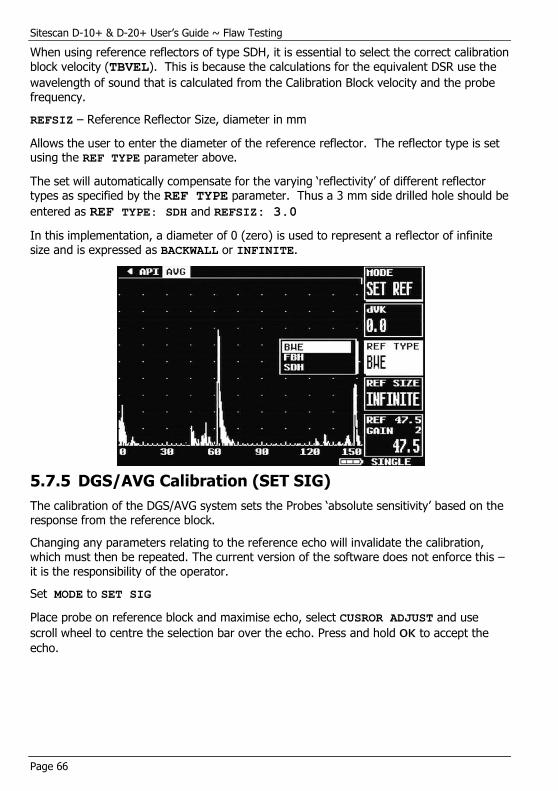
Sitescan D-10+ & D-20+ User’s Guide ~ Flaw Testing
Page 66
When using reference reflectors of type SDH, it is essential to select the correct calibration block velocity (TBVEL). This is because the calculations for the equivalent DSR use the
wavelength of sound that is calculated from the Calibration Block velocity and the probe frequency.
REFSIZ – Reference Reflector Size, diameter in mm
Allows the user to enter the diameter of the reference reflector. The reflector type is set using the REF TYPE parameter above.
The set will automatically compensate for the varying ‘reflectivity’ of different reflector types as specified by the REF TYPE parameter. Thus a 3 mm side drilled hole should be
entered as REF TYPE: SDH and REFSIZ: 3.0
In this implementation, a diameter of 0 (zero) is used to represent a reflector of infinite size and is expressed as BACKWALL or INFINITE.
5.7.5 DGS/AVG Calibration (SET SIG)
The calibration of the DGS/AVG system sets the Probes ‘absolute sensitivity’ based on the response from the reference block.
Changing any parameters relating to the reference echo will invalidate the calibration, which must then be repeated. The current version of the software does not enforce this – it is the responsibility of the operator.
Set MODE to SET SIG
Place probe on reference block and maximise echo, select CUSROR ADJUST and use
scroll wheel to centre the selection bar over the echo. Press and hold OK to accept the
echo.

Sitescan D-10+ & D-20+ User’s Guide ~ Flaw Testing
Page 67
The instrument will adjust gain as necessary to get a good echo reference and then
perform the necessary sensitivity calculations; the curve will then be drawn and DGS/AVG will automatically be switched on.
Once DGS/AVG has been switched on it is possible to adjust the curve ERS level (the instrument will redraw the curve, but a new calibration is not required) and select either the Curve or Gate as the measurement reference. It is also possible to make adjustments to the transfer loss parameter (T-LOSS).
5.7.6 Adjustment
When the DGS/AVG has been calibrated it is possible to leave the DGS/AVG menus and adjust other settings of the instrument, for example range and gate settings.

Sitescan D-10+ & D-20+ User’s Guide ~ Flaw Testing
Page 68
Gain may be adjusted with understanding – Changing the Gain setting will remove the correlation with the DGS/AVG curve, so should only be done in accordance with a specification , for example to compensate for varying material conditions (better done with the T-LOSS function).
If it is desired to change the gain to give a larger signal (for example at long range) the REF gain should be adjusted. This will change the curve by an equivalent amount and preserve the measurement accuracy.
Increasing REF Gain by 6dB moves curve and preserves measurement.

Sitescan D-10+ & D-20+ User’s Guide ~ Flaw Testing
Page 69
Decreasing Gain by 6dB returns to original height, but loses measurement.
The Reference gain may be selected by pressing the REF/GAIN Button. (DGS/AVG is
only appropriate for Single probe mode)
When the Display Range or REF Gain is changed the DGS/AVG curve will recalculate at each step. If the settings must be changed by more than one or two steps it may be more convenient to Switch DGS/AVG off, Change REF gain and range etc as needed, and then switch DGS/AVG on again. This will not invalidate the curve provided the following are not changed:
FREQ, NFL, dVK, DELAY, REF dB/m, TBVEL, REF TYPE, REFSIZ, (new
REFERENCE Entered), Probe Zero, Filter, Contour or Probe Angle.
The following should not be used in DGS/AVG Mode:
Detect Modes other than Full Wave, non-zero REJECT, Dual probe mode, Smoothing, AUTO-CAL (other than for initial setup before using DGS/AVG), DAC, AWS, API or AGC
5.7.7 Measurement
Having set up the DGS/AVG system, it is possible to use the measurement system to calculate an Equivalent Reflector Size for the flaw.
This is achieved by using Gate 1 to identify the flaw indication and the DEPTH measurement mode to calculate its equivalent size. This Equivalent Size is calculated as the Test Sensitivity (ERS value) multiplied by the Ratio of the Signal height to the DGS/AVG curve height at that distance. It is displayed in place of the signal amplitude (%FSH) as a diameter, in mm.
It is also possible to ‘size’ the flaw in terms of dB with respect to the DGS/AVG curve. This is achieved by increasing, or decreasing, the set gain until the peak of the flaw signal lies on the DGS/AVG curve. The difference in Gain required can then be read directly from the displayed Gain Value.
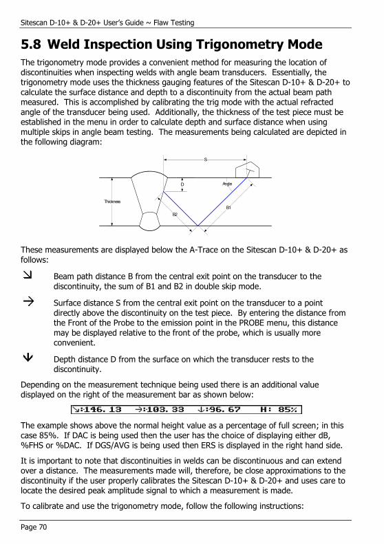
Sitescan D-10+ & D-20+ User’s Guide ~ Flaw Testing
Page 70
5.8 Weld Inspection Using Trigonometry Mode
The trigonometry mode provides a convenient method for measuring the location of discontinuities when inspecting welds with angle beam transducers. Essentially, the trigonometry mode uses the thickness gauging features of the Sitescan D-10+ & D-20+ to calculate the surface distance and depth to a discontinuity from the actual beam path measured. This is accomplished by calibrating the trig mode with the actual refracted angle of the transducer being used. Additionally, the thickness of the test piece must be established in the menu in order to calculate depth and surface distance when using multiple skips in angle beam testing. The measurements being calculated are depicted in the following diagram:
B1
B2
S
D
Thickness
Angle
These measurements are displayed below the A-Trace on the Sitescan D-10+ & D-20+ as follows:
Beam path distance B from the central exit point on the transducer to the discontinuity, the sum of B1 and B2 in double skip mode.
Surface distance S from the central exit point on the transducer to a point directly above the discontinuity on the test piece. By entering the distance from the Front of the Probe to the emission point in the PROBE menu, this distance may be displayed relative to the front of the probe, which is usually more convenient.
Depth distance D from the surface on which the transducer rests to the discontinuity.
Depending on the measurement technique being used there is an additional value displayed on the right of the measurement bar as shown below:
The example shows above the normal height value as a percentage of full screen; in this case 85%. If DAC is being used then the user has the choice of displaying either dB, %FHS or %DAC. If DGS/AVG is being used then ERS is displayed in the right hand side.
It is important to note that discontinuities in welds can be discontinuous and can extend over a distance. The measurements made will, therefore, be close approximations to the discontinuity if the user properly calibrates the Sitescan D-10+ & D-20+ and uses care to locate the desired peak amplitude signal to which a measurement is made.
To calibrate and use the trigonometry mode, follow the following instructions:
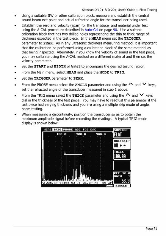
Sitescan D-10+ & D-20+ User’s Guide ~ Flaw Testing
Page 71
Using a suitable IIW or other calibration block, measure and establish the central sound beam exit point and actual refracted angle for the transducer being used.
Establish the zero and velocity (span) for the transducer and material under test using the A-CAL procedure described in Auto-Cal on page 90. Use a suitable calibration block that has two drilled holes representing the thin to thick range of thickness expected in the test piece. In the MEAS menu set the TRIGGER
parameter to PEAK. As in any ultrasonic thickness measuring method, it is important
that the calibration be performed using a calibration block of the same material as that being inspected. Alternately, if you know the velocity of sound in the test piece, you may calibrate using the A-CAL method on a different material and then set the velocity parameter.
Set the START and WIDTH of Gate1 to encompass the desired testing region.
From the Main menu, select MEAS and place the MODE to TRIG.
Set the TRIGGER parameter to PEAK.
From the PROBE menu select the ANGLE parameter and using the and keys,
set the refracted angle of the transducer measured in step 1 above.
From the TRIG menu select the THICK parameter and using the and keys
dial in the thickness of the test piece. You may have to readjust this parameter if the test piece had varying thickness and you are using a multiple skip mode of angle beam testing.
When measuring a discontinuity, position the transducer so as to obtain the maximum amplitude signal before recording the readings. A typical TRIG mode display is shown below.
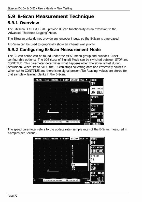
Sitescan D-10+ & D-20+ User’s Guide ~ Flaw Testing
Page 72
5.9 B-Scan Measurement Technique
5.9.1 Overview
The Sitescan D-10+ & D-20+ provide B-Scan functionality as an extension to the ‘Advanced Thickness Logging’ Mode.
The Sitescan units do not provide any encoder inputs, so the B-Scan is time-based.
A B-Scan can be used to graphically show an internal wall profile.
5.9.2 Configuring B-Scan Measurement Mode
The B-Scan option can be found under the MEAS menu group and provides 3 user configurable options: The LOS (Loss of Signal) Mode can be switched between STOP and CONTINUE. This parameter determines what happens when the signal is lost during acquisition. When set to STOP the B-Scan stops collecting data and effectively pauses it. When set to CONTINUE and there is no signal present ‘No Reading’ values are stored for that sample – leaving blanks in the B-Scan.
The speed parameter refers to the update rate (sample rate) of the B-Scan, measured in ‘Samples per Second’.

Sitescan D-10+ & D-20+ User’s Guide ~ Flaw Testing
Page 73
The N.O.S parameter refers to the ‘Number of Samples’ stored in the B-Scan; 250 is the maximum, with one pixel line per sample.
Once the above parameters have been chosen, B-Scan mode can be switched on. It is possible to adjust the SPEED and N.O.S with B-Scan mode switched on, however due to the B-Scans dependence on the values the B-Scan is cleared. The LOS MODE can be changed without clearing the B-Scan.
5.9.3 Using B-Scan Mode
Switching B-Scan mode on causes the screen to be resized, creating a half-size A-Scan and showing the B-Scan panel at the bottom. The B-Scan panel depth represents the range of the A-Scan, with the time-based aspect displayed across the width.
The minimum thickness (depth) in the currently shown B-Scan is displayed in the bottom left corner.
Shown below is an example B-Scan. The user is expected to select an appropriate scanning speed related to the SPEED parameter.
Setting the LOS MODE to STOP, when the user wants to stop or pause scanning, one should simply remove the transducer from the scanning surface.
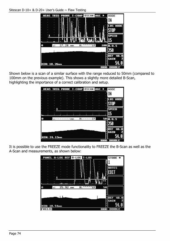
Sitescan D-10+ & D-20+ User’s Guide ~ Flaw Testing
Page 74
Shown below is a scan of a similar surface with the range reduced to 50mm (compared to 100mm on the previous example). This shows a slightly more detailed B-Scan, highlighting the importance of a correct calibration and setup.
It is possible to use the FREEZE mode functionality to FREEZE the B-Scan as well as the A-Scan and measurements, as shown below:

Sitescan D-10+ & D-20+ User’s Guide ~ Flaw Testing
Page 75
5.10 Temperature Compensation
5.10.1 Overview
The Sitescan D-10+ & D-20+ provide, as a standard option, a ‘temperature compensation feature’ (T-COMP) to enable measurements to be corrected for a temperature disparity between a calibration block and the actual material under test. This feature can be found under the MEAS menu group.
The temperature compensation feature does not operate in trigonometric measurement mode due to the correction required for change in refractive index of the wedge material.
It allows users to calibrate and measure accurately between -250 ºC and 1000 ºC.
5.10.2 The Calculation
The calculation used to correct the beam path measurement in the Sitescan D-10+ & D-20+ is shown below:
Corrected_Beam_Path = TOF * V(1 - k(T₁ - T₀))
Where TOF is the time of flight, V is the calibrated velocity, k is the temperature
coefficient of the material, T₀ is the temperature at calibration and T₁ is the measured
temperature.
5.10.3 Configuring Temperature Compensation
Temperature compensation provides 3 configurable parameters. These must be set correctly to enable the feature to accurately compensate the measurements:
CAL ºC’ The temperature of the calibration block.
‘MAT ºC’ The temperature of the material under inspection.
‘k’ The temperature coefficient of the material. This parameter allows free adjustment, defaulting to the value for Steel.
‘
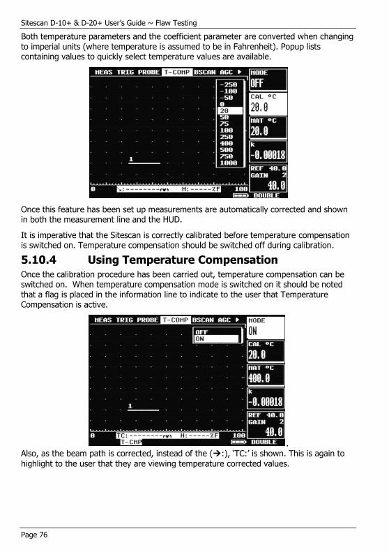
Sitescan D-10+ & D-20+ User’s Guide ~ Flaw Testing
Page 76
Both temperature parameters and the coefficient parameter are converted when changing to imperial units (where temperature is assumed to be in Fahrenheit). Popup lists containing values to quickly select temperature values are available.
Once this feature has been set up measurements are automatically corrected and shown in both the measurement line and the HUD.
It is imperative that the Sitescan is correctly calibrated before temperature compensation is switched on. Temperature compensation should be switched off during calibration.
5.10.4 Using Temperature Compensation
Once the calibration procedure has been carried out, temperature compensation can be switched on. When temperature compensation mode is switched on it should be noted that a flag is placed in the information line to indicate to the user that Temperature Compensation is active.
. Also, as the beam path is corrected, instead of the (:), ‘TC:’ is shown. This is again to
highlight to the user that they are viewing temperature corrected values.
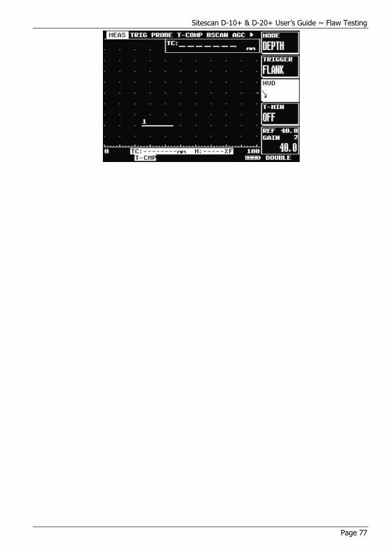
Sitescan D-10+ & D-20+ User’s Guide ~ Flaw Testing
Page 77
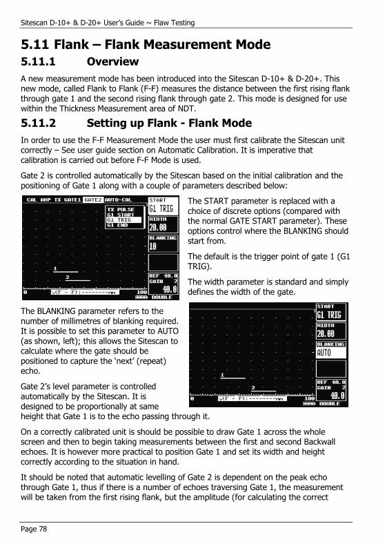
Sitescan D-10+ & D-20+ User’s Guide ~ Flaw Testing
Page 78
5.11 Flank – Flank Measurement Mode
5.11.1 Overview
A new measurement mode has been introduced into the Sitescan D-10+ & D-20+. This new mode, called Flank to Flank (F-F) measures the distance between the first rising flank through gate 1 and the second rising flank through gate 2. This mode is designed for use within the Thickness Measurement area of NDT.
5.11.2 Setting up Flank - Flank Mode
In order to use the F-F Measurement Mode the user must first calibrate the Sitescan unit correctly – See user guide section on Automatic Calibration. It is imperative that calibration is carried out before F-F Mode is used.
Gate 2 is controlled automatically by the Sitescan based on the initial calibration and the
positioning of Gate 1 along with a couple of parameters described below:
The START parameter is replaced with a choice of discrete options (compared with the normal GATE START parameter). These options control where the BLANKING should start from.
The default is the trigger point of gate 1 (G1 TRIG).
The width parameter is standard and simply defines the width of the gate.
The BLANKING parameter refers to the number of millimetres of blanking required. It is possible to set this parameter to AUTO (as shown, left); this allows the Sitescan to calculate where the gate should be positioned to capture the ‘next’ (repeat) echo.
Gate 2’s level parameter is controlled automatically by the Sitescan. It is designed to be proportionally at same height that Gate 1 is to the echo passing through it.
On a correctly calibrated unit is should be possible to draw Gate 1 across the whole screen and then to begin taking measurements between the first and second Backwall echoes. It is however more practical to position Gate 1 and set its width and height correctly according to the situation in hand.
It should be noted that automatic levelling of Gate 2 is dependent on the peak echo through Gate 1, thus if there is a number of echoes traversing Gate 1, the measurement will be taken from the first rising flank, but the amplitude (for calculating the correct
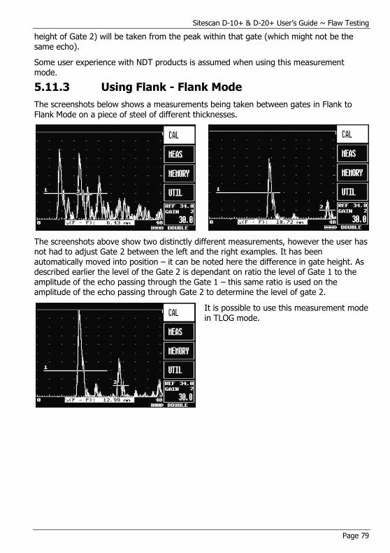
Sitescan D-10+ & D-20+ User’s Guide ~ Flaw Testing
Page 79
height of Gate 2) will be taken from the peak within that gate (which might not be the same echo).
Some user experience with NDT products is assumed when using this measurement mode.
5.11.3 Using Flank - Flank Mode
The screenshots below shows a measurements being taken between gates in Flank to Flank Mode on a piece of steel of different thicknesses.
The screenshots above show two distinctly different measurements, however the user has not had to adjust Gate 2 between the left and the right examples. It has been automatically moved into position – it can be noted here the difference in gate height. As described earlier the level of the Gate 2 is dependant on ratio the level of Gate 1 to the amplitude of the echo passing through the Gate 1 – this same ratio is used on the amplitude of the echo passing through Gate 2 to determine the level of gate 2.
It is possible to use this measurement mode in TLOG mode.
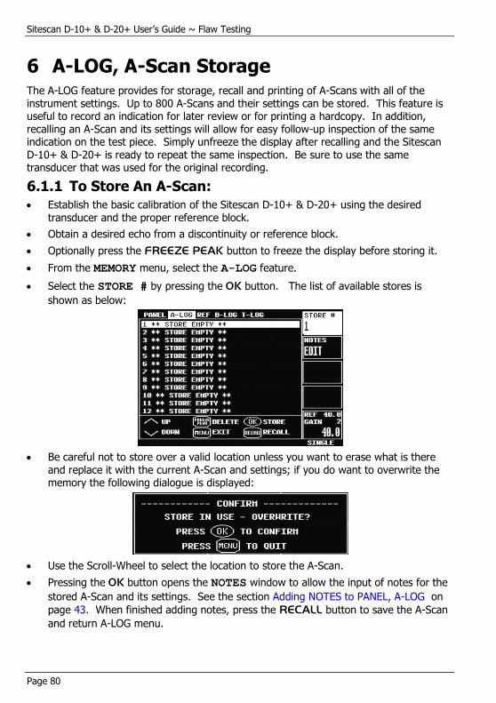
Sitescan D-10+ & D-20+ User’s Guide ~ Flaw Testing
Page 80
6 A-LOG, A-Scan Storage The A-LOG feature provides for storage, recall and printing of A-Scans with all of the instrument settings. Up to 800 A-Scans and their settings can be stored. This feature is useful to record an indication for later review or for printing a hardcopy. In addition, recalling an A-Scan and its settings will allow for easy follow-up inspection of the same indication on the test piece. Simply unfreeze the display after recalling and the Sitescan D-10+ & D-20+ is ready to repeat the same inspection. Be sure to use the same transducer that was used for the original recording.
6.1.1 To Store An A-Scan:
Establish the basic calibration of the Sitescan D-10+ & D-20+ using the desired transducer and the proper reference block.
Obtain a desired echo from a discontinuity or reference block.
Optionally press the FREEZE PEAK button to freeze the display before storing it.
From the MEMORY menu, select the A-LOG feature.
Select the STORE # by pressing the OK button. The list of available stores is
shown as below:
Be careful not to store over a valid location unless you want to erase what is there and replace it with the current A-Scan and settings; if you do want to overwrite the memory the following dialogue is displayed:
Use the Scroll-Wheel to select the location to store the A-Scan.
Pressing the OK button opens the NOTES window to allow the input of notes for the
stored A-Scan and its settings. See the section Adding NOTES to PANEL, A-LOG on
page 43. When finished adding notes, press the RECALL button to save the A-Scan
and return A-LOG menu.

Sitescan D-10+ & D-20+ User’s Guide ~ Flaw Testing
Page 81
6.1.2 Thumbnail Viewer
The functionality of the A-LOG menu has been extended to include a thumbnail view.
When scanning down the list of stored A-Logs, if the user pauses for a couple of seconds the thumbnail view is activated showing an A-Scan thumb along with any notes stored with the A-Scan – this enables a quick look at the A-Scan and the full notes without actually having to recall it. This can be seen on the below:
Pressing the RECALL key here will cause the A-Log to be recalled as normal – otherwise scrolling up and down or pressing the MENU key will remove the thumbnail view.
6.1.3 To Recall an A-Scan:
From the MEMORY menu, select the A-LOG feature.
Select the STORE # by pressing the OK button. The list of available stores is the
same as that for storing an A-Scan
Use the Scroll-Wheel to select the A-Scan to recall then press the RECALL button.
This may take a couple of seconds after which the display will be in FREEZE mode
and the label of the A-LOG is displayed at the bottom of the display.
To return to normal testing mode with the recalled settings, press the FREEZE
PEAK button.
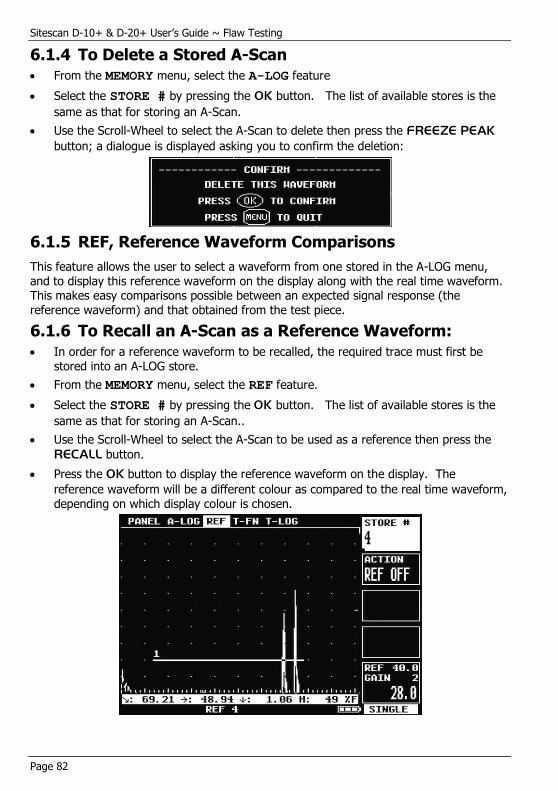
Sitescan D-10+ & D-20+ User’s Guide ~ Flaw Testing
Page 82
6.1.4 To Delete a Stored A-Scan
From the MEMORY menu, select the A-LOG feature
Select the STORE # by pressing the OK button. The list of available stores is the
same as that for storing an A-Scan.
Use the Scroll-Wheel to select the A-Scan to delete then press the FREEZE PEAK
button; a dialogue is displayed asking you to confirm the deletion:
6.1.5 REF, Reference Waveform Comparisons
This feature allows the user to select a waveform from one stored in the A-LOG menu, and to display this reference waveform on the display along with the real time waveform. This makes easy comparisons possible between an expected signal response (the reference waveform) and that obtained from the test piece.
6.1.6 To Recall an A-Scan as a Reference Waveform:
In order for a reference waveform to be recalled, the required trace must first be stored into an A-LOG store.
From the MEMORY menu, select the REF feature.
Select the STORE # by pressing the OK button. The list of available stores is the
same as that for storing an A-Scan..
Use the Scroll-Wheel to select the A-Scan to be used as a reference then press the
RECALL button.
Press the OK button to display the reference waveform on the display. The
reference waveform will be a different colour as compared to the real time waveform, depending on which display colour is chosen.

Sitescan D-10+ & D-20+ User’s Guide ~ Flaw Testing
Page 83
To remove the reference waveform, select ACTION REF OFF and press the OK
button.
NOTE: When the reference is recalled, no setting parameters are changed. Therefore, if the RANGE VELOCITY or DELAY are changed, the reference signal will not match the
real time waveform. This means that the RANGE, VELOCITY and DELAY used for
storing the reference waveform in A-LOG must match that used for the comparison of real time signals to the reference waveform.
6.1.7 Peak Echo & Hold Dynamics
During flaw testing it is sometimes difficult to determine the exact peak of a discontinuity echo due to its geometry, coupling and surface anomalies and part geometry. The Sitescan D-10+ & D-20+ incorporates a Peak feature that, while activated, stores all of the signal excursions on the display.
In addition to providing an effective method of capturing peak echo information, the Peak mode is useful for crack tip diffraction methods in angle beam weld inspection. In the case of crack tip diffraction, the extent of a crack type discontinuity can be inferred by the positional excursions of the signal as it reflects from both tips of a crack. Thus, as the transducer is moved past the indication, the signals will be “filled-in” on the display and the resultant width of the envelope or “echo dynamic pattern” will infer the crack length.
To use the echo dynamic pattern feature, position the transducer just off one side of the
indication. Press the FREEZE PEAK button twice to activate the Peak mode which is
indicated by a box-displaying PEAK below the graticule. Move the transducer past the indication to display the envelope pattern. In the case of angle beam testing, it is advisable to rotate the transducer slightly and move it from side to side while moving forward past the indication. This will assure the capturing of all amplitude and distance
information. An example of peak echo mode capture is shown below:
The envelope can be changed between outline as shown above and filled-in by selecting the SMOOTH parameter and switching between SMOOTH and FILL.
To return the display to normal mode, press and hold the FREEZE PEAK button. This
will erase the envelope pattern and return the instrument to the instantaneous mode of
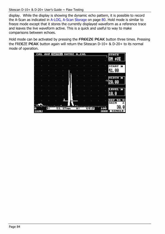
Sitescan D-10+ & D-20+ User’s Guide ~ Flaw Testing
Page 84
display. While the display is showing the dynamic echo pattern, it is possible to record the A-Scan as indicated in A-LOG, A-Scan Storage on page 80. Hold mode is similar to freeze mode except that it stores the currently displayed waveform as a reference trace
and leaves the live waveform active. This is a quick and useful to way to make comparisons between echoes.
Hold mode can be activated by pressing the FREEZE PEAK button three times. Pressing
the FREEZE PEAK button again will return the Sitescan D-10+ & D-20+ to its normal
mode of operation.
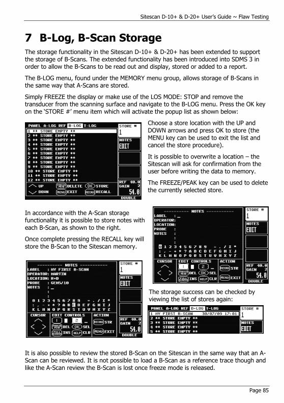
Sitescan D-10+ & D-20+ User’s Guide ~ Flaw Testing
Page 85
7 B-Log, B-Scan Storage The storage functionality in the Sitescan D-10+ & D-20+ has been extended to support the storage of B-Scans. The extended functionality has been introduced into SDMS 3 in order to allow the B-Scans to be read out and display, stored or added to a report.
The B-LOG menu, found under the MEMORY menu group, allows storage of B-Scans in the same way that A-Scans are stored.
Simply FREEZE the display or make use of the LOS MODE: STOP and remove the transducer from the scanning surface and navigate to the B-LOG menu. Press the OK key on the ‘STORE #’ menu item which will activate the popup list as shown below:
Choose a store location with the UP and DOWN arrows and press OK to store (the
MENU key can be used to exit the list and cancel the store procedure).
It is possible to overwrite a location – the Sitescan will ask for confirmation from the user before writing the data to memory.
The FREEZE/PEAK key can be used to delete the currently selected store.
In accordance with the A-Scan storage functionality it is possible to store notes with
each B-Scan, as shown to the right.
Once complete pressing the RECALL key will store the B-Scan to the Sitescan memory.
The storage success can be checked by viewing the list of stores again:
It is also possible to review the stored B-Scan on the Sitescan in the same way that an A-Scan can be reviewed. It is not possible to load a B-Scan as a reference trace though and like the A-Scan review the B-Scan is lost once freeze mode is released.
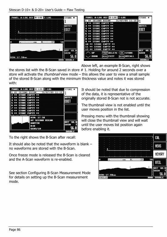
Sitescan D-10+ & D-20+ User’s Guide ~ Flaw Testing
Page 86
Above left, an example B-Scan, right shows the stores list with the B-Scan saved in store # 1. Holding for around 2 seconds over a store will activate the thumbnail view mode – this allows the user to view a small sample of the stored B-Scan along with the minimum thickness value and notes it was stored with:
It should be noted that due to compression of the data, it is representative of the originally stored B-Scan not is not accurate.
The thumbnail view is not enabled until the user moves position in the list.
Pressing menu with the thumbnail showing will close the thumbnail view and will wait until the user moves list position again before enabling it.
To the right shows the B-Scan after recall:
It should also be noted that the waveform is blank – no waveforms are stored with the B-Scan.
Once freeze mode is released the B-Scan is cleared and the A-Scan waveform is re-enabled.
See section Configuring B-Scan Measurement Mode for details on setting up the B-Scan measurement mode.

Sitescan D-10+ & D-20+ User’s Guide ~ Thickness Gauging
Page 87
8 Thickness Gauging
8.1 Basic Thickness Gauging
Accurate and reliable thickness gauging requires three important considerations:
a) Proper transducer selection
b) An accurate reference block of the same material as that being tested, and
c) Proper calibration of the instrument.
There are three types of transducers used in ultrasonic thickness gauging, all employing the straight or longitudinal beam method. The single element contact transducer is used for general purpose thickness gauging where material thickness is generally expected to
be above 2.5mm. The delay line contact transducer is used for measuring thin material down to 0.5mm where the surfaces are clean and parallel. The dual element contact transducer is used for moderately thin materials down to about 1.0mm where the surfaces may be irregular and not necessarily parallel. The dual transducer is most commonly used for corrosion thickness inspection where its ability to obtain echoes from a pitted surface is superior. Nevertheless, dual transducer inspection on corroded materials is nowhere near as accurate as single element and delay line inspection, due to the nature of the material under test. In addition, the dual element transducer usually incorporates a slight included angle on both the transmit and receive side, resulting in a small non-linearity of the measurements. For this reason, dual transducer thickness testing is usually calibrated and performed over a limited thickness range.
Regardless of the type of transducer used, it is important that it be specifically designed for thickness gauging. This means that it must have broadband or highly damped characteristics that provide a sharp leading edge. Otherwise, amplitude variations of the signals can cause half-wavelength errors due to smaller “build-up”
The next requirement for thickness gauging is a calibration or reference block. This block should be made of the same material as the components to be inspected. In other words, it should have the same sound velocity and attenuation characteristics. The calibration block should have parallel machined surfaces representing the thickness range to be inspected. Although two thicknesses representing the minimum and maximum values are sufficient for calibration, it is recommended that the calibration block have four sections covering the range anticipated. This will allow for verification of the calibration.
It is possible to calibrate the Sitescan D-10+ & D-20+ using a generic test block and only
one known sample thickness of the material under inspection. This is a less desirable method because there is no way of verifying the calibration. With this method, the calibration would first be performed on the generic test block, which would have three to four sections covering the expected thickness range. Essentially, calibrating on the generic block would set the transducer zero point. Then the Sitescan D-10+ & D-20+ Velocity would be adjusted on the known sample of the test material until the thickness readout matched the known thickness. This established the sound velocity for the test material.

Sitescan D-10+ & D-20+ User’s Guide ~ Thickness Gauging
Page 88
Finally, it is necessary to establish the proper calibration of the Sitescan D-10+ & D-20+ in order to assure accurate and reliable thickness testing. The essence of this calibration is to set the pulser and amplifier characteristics to provide sharp leading edges on the
echoes. The following are the essential steps for basic thickness gauging:
Select the appropriate broadband transducer and calibration block that matches the material under test.
In the CAL menu, select the proper RANGE and DELAY so those echoes from the
range of thickness can be viewed.
From the AMP menu, set the FREQ to the nominal value of the transducer (D-20+
only) and set the detection mode to RF.
From the TX menu select SINGLE for delay line and single element transducers and
DOUBLE for dual element transducers.
Couple the transducer to a mid-range thickness section on the calibration block and
obtain an echo.
From the AMP menu, set the DETECT parameter to either –VE HW or +VE HW,
depending on which half of the RF provides the best half-cycle as determined above.
Adjust the gain to set the echo at about 80 %FSH and increase the REJECT
parameter to remove any undesirable noise from the baseline.
From the GATE1 menu, set the gate to ON +VE and adjust the START and WIDTH
so that the gate encompasses the thickness range of interest. Place the transducer between the thin and thick area on the calibration block to verify proper coverage. Adjust the LEVEL parameter to about 30 %FSH.
From the MEAS menu, set the MODE parameter to DEPTH and the TRIGGER
parameter to FLANK.
If desired, set the T-MIN parameter to ON so that the thinnest reading obtained will
be held in the display.
If desired, set the HUD parameter to ON to display the thickness in a large window at
the top right of the display.
To calibrate the Sitescan D-10+ & D-20+ for thickness readings, follow the steps outlined in Auto-Cal on page 90. Alternately, you can use an iterative process from the CAL menu of setting the ZERO on the thinnest calibration block sample and the
VELOCITY on the thickest sample. Using this technique, you must repeat ZERO to
VELOCITY several times until the two values are correct.
When using a delay line transducer, there are two modes of measurement:
a) Interface to first return echo, and
b) Multiple echo mode which usually measures from the first to the second return echoes after the interface echo.
The Sitescan D-10+ & D-20+ with Advanced Thickness provide two multiple echo measurement modes:
a) Echo – Echo (E-E)

Sitescan D-10+ & D-20+ User’s Guide ~ Thickness Gauging
Page 89
From the MEAS menu, set the MODE to E-E for echo to echo measurement. You
will notice that a second gate bar appears below gate 1 and that its start point is slightly to the right of gate 1. This is the blanking gate explained below.
For measuring from interface to first echo, position the start of gate 1 before the interface echo. Using the BLANK parameter in the MEAS menu, position the start of
the second gate just after the interface echo but before the thinnest expected first echo.
For measuring multiple echoes after the interface, position the start of gate1 just after the interface echo. Using the BLANK parameter in the MEAS menu, position
the start of the second gate just after the first echo but before the thinnest expected second echo.
The BLANK parameter determines the blanking or starting position of the second
gate relative to the starting position of gate1. This prevents noise and spurious echoes associated with the interface or first echo from terminating the measurement and producing a false reading.
b) Flank – Flank (F-F)
From the MEAS menu, set the MODE to F-F for flank to flank measurement. You
will notice that a second gate appears below and to the right of gate 1. The gate 2 has 3 parameters for controlling this automatic gate (START, WIDTH and
BLANKING).
For a correctly calibrated Sitescan gate 1 can be positioned and with the BLANKING
parameter set to AUTO, gate 2 should position itself correctly over the second echo.
It should be noted that the blanking parameter works differently to the blanking parameter in echo – echo mode. In flank – flank mode the blanking is measured in
timebase units – as opposed to a percentage of gate 1 as in echo – echo mode.
For storage of thickness readings, refer to Thickness Gauging on page 87.
Sitescan D-10+ & D-20+ User’s Guide ~ Thickness Gauging
Page 90
8.2 Auto-Cal
AUTO-CAL is an automated calibration feature for thickness gauging applications or when measuring depth to an indication in flaw testing.
In order to achieve proper calibration for measuring time-of-flight in ultrasonic testing, two factors must be known; the velocity of sound in the material under test, and the offset of the transducer caused by wear face and phase shifts.
Conventional thickness calibration technique usually requires setting the zero (offset) and span (velocity) using an iterative technique. This means alternately placing the transducer on a thin sample to set the zero and a thick sample to set the span. This process is repeated several times until both readings are correct. The reason for this is that raising the span will also raise the zero.
The AUTO-CAL feature automates this process so that only two readings are required, one
on the thin sample and one on the thick sample. The Sitescan D-10+ & D-20+ then calculates the correct offset and span factors and sets the velocity and zero. Any time the test material is changed (velocity) or the transducer is changed (zero); this procedure must be repeated. Using this procedure will result in quicker calibration of the instrument and more accurate measurements.
The AUTO-CAL calibration procedure is as follows:
Select a test block of the same material as that being inspected, with reference thickness covering the minimum to maximum thickness expected in the test parts. The difference between the thick sample and the thin sample should be no less than five to one.
From the main menu, select CAL and adjust the RANGE and DELAY so that the thin
and thick reference echoes show on the display.
From the CAL menu, select GATE1 and place the STATE in ON +VE. Adjust the
START and WIDTH of the gate to encompass the echoes from the thin and thick
samples.
From the main menu, select MEAS and place the MODE to DEPTH.
From the CAL menu, select the AUTO-CAL menu.
Select DIST1 using by pressing the OK button to list common thicknesses then use
the Scroll-Wheel to select the desired value. If the required value is not shown in the
list then select the value closest to it by pressing the OK key then press and hold
down the OK key until the value is highlighted then use the Scroll-Wheel to change
the value using the Scroll-Wheel; once the value is correct press the OK key again to
exit from the DIST1 parameter. Repeat this for the DIST2 parameter.
Place the transducer on the thin reference sample and obtain an echo. Adjust the gate start if necessary to obtain distance readout of the echo.
Select the ACCEPT DIST1 parameter box and press OK to log the echo; the
ACCEPT parameter box will show DIST2.
Place the transducer on the thick reference sample and obtain an echo. Adjust the gate width if necessary to obtain distance readout of the echo.
Sitescan D-10+ & D-20+ User’s Guide ~ Thickness Gauging
Page 91
Press the OK button to log the echo; the ACCEPT parameter box will show CAL
Press the OK button. The transducer zero and velocity will now be adjusted.
The DIST1 and DIST2 values can be stored when the calibration information in PANEL
and A-LOG functions are stored. This overcomes the need to set these values and gate
positions every time a calibration is desired. Once established, all that is required is to
obtain each echo and press OK, and the instrument is calibrated.
If a delay transducer is used set DIST1 to 0.0 and use the interface echo as the thin
reference echo. The instrument will then set the transducer zero to compensate for the delay line.
Once calibrated, it might be desirable to record the velocity and zero values from the CAL menu for future reference. Note that this is a convenient method for determining the velocity of sound in an unknown material. Once the Sitescan D-10+ & D-20+ is calibrated on a known material, all that needs to be known is one fixed thickness point and the velocity can be determined.
8.3 TCG for Reliable Gauging
As previously mentioned, reliable thickness gauging requires that the shape of the echoes be consistent with sharp leading edges. When measuring the thickness of material with higher than normal attenuation to ultrasonic energy or a wide thickness range, it is difficult to maintain proper characteristics of the echoes. One way to overcome this is to use the Time Corrected Gain feature of the Sitescan D-10+ & D-20+. TCG can improve the reliability of thickness gauging by increasing the amplitude of echoes from thicker sections of the test material so as to maintain the correct detection threshold on the leading edge. The objective is to equalize the amplitude of echoes over the entire
thickness range to be expected.
To set up the TCG feature, refer to TCG Operation on page 51.
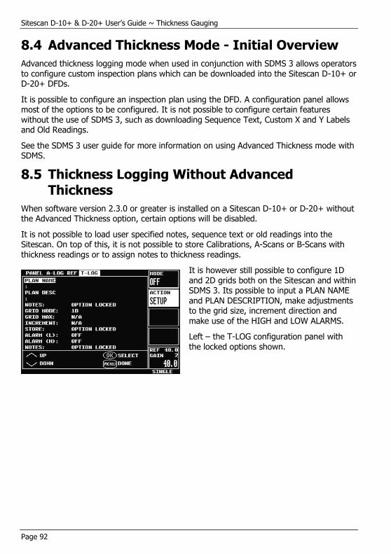
Sitescan D-10+ & D-20+ User’s Guide ~ Thickness Gauging
Page 92
8.4 Advanced Thickness Mode - Initial Overview
Advanced thickness logging mode when used in conjunction with SDMS 3 allows operators to configure custom inspection plans which can be downloaded into the Sitescan D-10+ or D-20+ DFDs.
It is possible to configure an inspection plan using the DFD. A configuration panel allows most of the options to be configured. It is not possible to configure certain features without the use of SDMS 3, such as downloading Sequence Text, Custom X and Y Labels and Old Readings.
See the SDMS 3 user guide for more information on using Advanced Thickness mode with SDMS.
8.5 Thickness Logging Without Advanced Thickness
When software version 2.3.0 or greater is installed on a Sitescan D-10+ or D-20+ without the Advanced Thickness option, certain options will be disabled.
It is not possible to load user specified notes, sequence text or old readings into the Sitescan. On top of this, it is not possible to store Calibrations, A-Scans or B-Scans with thickness readings or to assign notes to thickness readings.
It is however still possible to configure 1D and 2D grids both on the Sitescan and within SDMS 3. Its possible to input a PLAN NAME and PLAN DESCRIPTION, make adjustments to the grid size, increment direction and make use of the HIGH and LOW ALARMS.
Left – the T-LOG configuration panel with the locked options shown.

Sitescan D-10+ & D-20+ User’s Guide ~ Thickness Gauging
Page 93
8.6 Using Advanced TLOG Mode
8.6.1 Setting up an inspection plan on the DFD
Selecting the TLOG Menu (Under Memory) and pressing ok on the ACTION parameter SETUP will activate a popup menu inviting the user to either create a new inspection plan or load a previously saved one.
Pressing the User Assigned Key labelled ‘1’ will activate the configuration panel providing the user with all of the available options: The panel to the left shows the options available to the user.
Using the Up and Down keys on the scroll wheel to select the desired field and then pressing the OK key to select that field for adjustment.
To enter a plan name (analogous with a file name) for the inspection plan press enter on the PLAN NAME field.
This will activate the text entry panel shown to the right. Enter the desired text and when complete press the MENU key to exit and return to the configuration panel shown above. The same method should be used to enter text into the ‘PLAN DESC’ field.

Sitescan D-10+ & D-20+ User’s Guide ~ Thickness Gauging
Page 94
The panel to the right shows a configuration panel with completed plan name and description fields. It is possible
to enter up to 32 characters of text into both fields.
Next to the notes field shows 15 ‘X’ characters, each one relates to a specific field (1 - 15) of the user defined notes. To edit the user notes press OK when the NOTES field is highlighted. This will activate the user notes entry panel which can be seen below editing note field 1:
Selecting a field using the UP and DOWN arrows and the pressing the OK key will
again activate the text entry panel, as shown to the left.
Enter the desired text for the selected note field pressing MENU when complete to return to the notes index list – as shown below. Each note field can be 32 characters long.
Once the desired note fields have been entered pressing MENU again will close the notes panel and return to the configuration
panel. It can be seen below the difference in the characters next to the notes field.
The first four fields are represented by tick characters – this denotes that they have been configured:
The GRID MODE option allows the operator to choose the grid mode – 1D grid or 2D grid. When 2D grid mode is selected the following two parameters (GRID MAX and
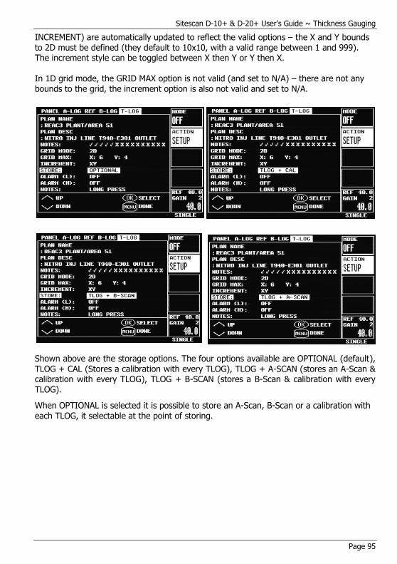
Sitescan D-10+ & D-20+ User’s Guide ~ Thickness Gauging
Page 95
INCREMENT) are automatically updated to reflect the valid options – the X and Y bounds to 2D must be defined (they default to 10x10, with a valid range between 1 and 999). The increment style can be toggled between X then Y or Y then X.
In 1D grid mode, the GRID MAX option is not valid (and set to N/A) – there are not any bounds to the grid, the increment option is also not valid and set to N/A.
Shown above are the storage options. The four options available are OPTIONAL (default), TLOG + CAL (Stores a calibration with every TLOG), TLOG + A-SCAN (stores an A-Scan & calibration with every TLOG), TLOG + B-SCAN (stores a B-Scan & calibration with every TLOG).
When OPTIONAL is selected it is possible to store an A-Scan, B-Scan or a calibration with each TLOG, it selectable at the point of storing.

Sitescan D-10+ & D-20+ User’s Guide ~ Thickness Gauging
Page 96
When TLOG Mode is switched on the alarm LED’s 1 & 2 and no longer controlled by gate transitions but by the ALARM (L) and
the ALARM (H) parameters – if the thickness value is lower than the ALARM (L) value then the LED 1 will be illuminated. If the thickness value is above ALARM (H) then the LED 2 will be illuminated.
The alarm values can be set between OFF and 999.99. The
final option relates to the action to be taken when a thickness value is stored. If set to its default value (LONG PRESS) then the notes panel shown in
section 2.2 will popup during the store process (only if the user presses and holds the OK button when storing a thickness reading). If set to ALWAYS ASK, as shown to the right, then the notes panel will be activated every time the store operation is carried out.
Once the options detailed in this section have been configured it pressing the MENU key will prompt the user to save the inspection plan, as shown below:
It is possible at this point to cancel the storing process by pressing the MENU key.
Pressing OK will attempt to store the inspection plan in the next available store.
Inspection plans are loaded and stored independent of PANELS. This allows the operator to have various PANELS configured within the Sitescan D-10+ or D-20+ and load them without having to re-load an inspection plan. It is also possible to view the inspection plan configuration and make adjustments to some of the options. Pressing OK on the ACTION: SETUP parameter again will show the EDIT option when a plan is loaded.
The GRID MODE and GRID MAX parameters are locked once the inspection plan has been configured – it is not possible to edit these fields.
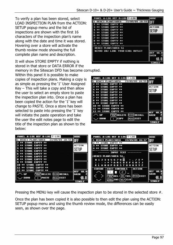
Sitescan D-10+ & D-20+ User’s Guide ~ Thickness Gauging
Page 97
To verify a plan has been stored, select LOAD INSPECTION PLAN from the ACTION: SETUP popup menu and the list of inspections are shown with the first 16 characters of the inspection plan’s name along with the date and time it was stored. Hovering over a store will activate the thumb review mode showing the full complete plan name and description.
It will show STORE EMPTY if nothing is stored in that store or DATA ERROR if the memory in the Sitescan DFD has become corrupted. Within this panel it is possible to make copies of inspection plans. Making a copy is
as simple as pressing the ‘1’ User Assigned Key – This will take a copy and then allow the user to select an empty store to paste the inspection plan into. Once a plan has been copied the action for the ‘1’ key will change to PASTE. Once a store has been selected to paste into pressing the ‘1’ key will initiate the paste operation and take the user the edit notes page to edit the title of the inspection plan as shown to the below:
Pressing the MENU key will cause the inspection plan to be stored in the selected store #.
Once the plan has been copied it is also possible to then edit the plan using the ACTION: SETUP popup menu and using the thumb review mode, the differences can be easily seen, as shown over the page.
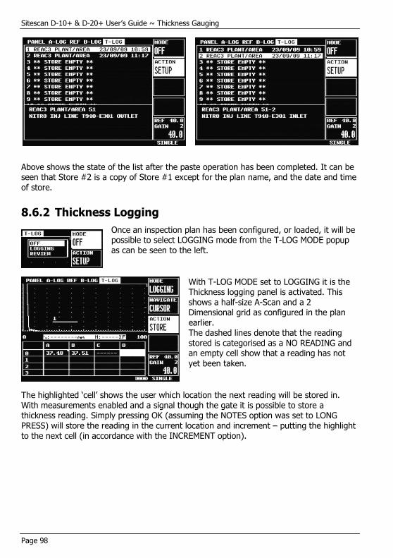
Sitescan D-10+ & D-20+ User’s Guide ~ Thickness Gauging
Page 98
Above shows the state of the list after the paste operation has been completed. It can be seen that Store #2 is a copy of Store #1 except for the plan name, and the date and time
of store.
8.6.2 Thickness Logging
Once an inspection plan has been configured, or loaded, it will be possible to select LOGGING mode from the T-LOG MODE popup as can be seen to the left.
With T-LOG MODE set to LOGGING it is the Thickness logging panel is activated. This shows a half-size A-Scan and a 2 Dimensional grid as configured in the plan earlier. The dashed lines denote that the reading stored is categorised as a NO READING and an empty cell show that a reading has not yet been taken.
The highlighted ‘cell’ shows the user which location the next reading will be stored in. With measurements enabled and a signal though the gate it is possible to store a thickness reading. Simply pressing OK (assuming the NOTES option was set to LONG PRESS) will store the reading in the current location and increment – putting the highlight to the next cell (in accordance with the INCREMENT option).
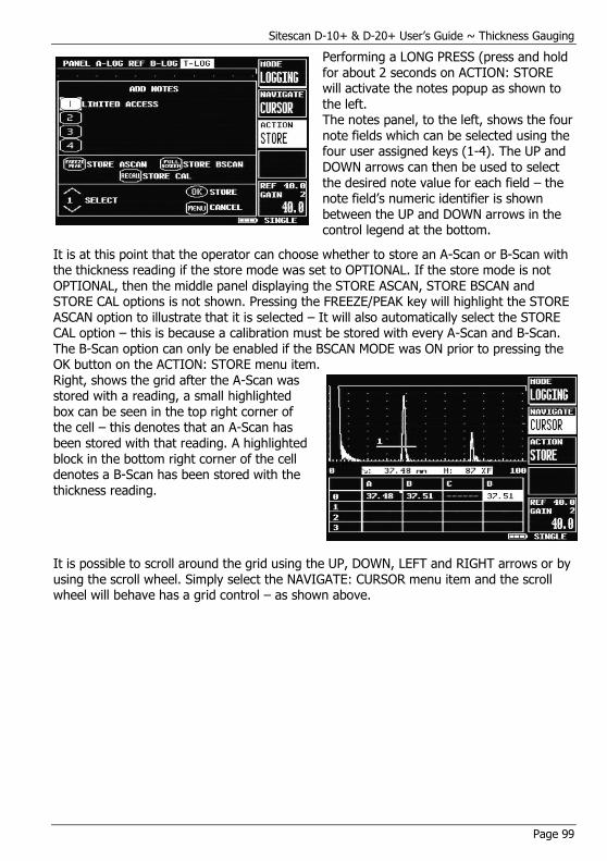
Sitescan D-10+ & D-20+ User’s Guide ~ Thickness Gauging
Page 99
Performing a LONG PRESS (press and hold for about 2 seconds on ACTION: STORE will activate the notes popup as shown to
the left. The notes panel, to the left, shows the four note fields which can be selected using the four user assigned keys (1-4). The UP and DOWN arrows can then be used to select the desired note value for each field – the note field’s numeric identifier is shown between the UP and DOWN arrows in the control legend at the bottom.
It is at this point that the operator can choose whether to store an A-Scan or B-Scan with the thickness reading if the store mode was set to OPTIONAL. If the store mode is not
OPTIONAL, then the middle panel displaying the STORE ASCAN, STORE BSCAN and STORE CAL options is not shown. Pressing the FREEZE/PEAK key will highlight the STORE ASCAN option to illustrate that it is selected – It will also automatically select the STORE CAL option – this is because a calibration must be stored with every A-Scan and B-Scan. The B-Scan option can only be enabled if the BSCAN MODE was ON prior to pressing the OK button on the ACTION: STORE menu item. Right, shows the grid after the A-Scan was stored with a reading, a small highlighted box can be seen in the top right corner of the cell – this denotes that an A-Scan has been stored with that reading. A highlighted block in the bottom right corner of the cell denotes a B-Scan has been stored with the
thickness reading.
It is possible to scroll around the grid using the UP, DOWN, LEFT and RIGHT arrows or by using the scroll wheel. Simply select the NAVIGATE: CURSOR menu item and the scroll wheel will behave has a grid control – as shown above.

Sitescan D-10+ & D-20+ User’s Guide ~ Thickness Gauging
Page 100
8.6.3 Review Mode
It is possible to review the thickness
readings in a larger (full screen grid), chosen via the T-LOG MODE menu item, review mode shown left is simply a larger grid which is automatically in NAVIGATE mode – pressing menu will exit this mode and return to the previous screen.
Hovering over a view for a couple of seconds will activate
the thumbnail view. If an A or B Scan is stored a small thumb will be shown along with any notes, see right.

Sitescan D-10+ & D-20+ User’s Guide ~ Thickness Gauging
Page 101
8.6.4 B-Scan’s
It has been mentioned that it is possible to store a B-Scan with a thickness reading. The
BSCAN menu which can be found under the MEAS menu group is where all the BSCAN configuration takes place. See the section B-Scan Measurement Technique for information relating to the setup and operation.
When an inspection plan is configured with B-SCAN storage an extra option is available in the T-LOG menu: BSCAN: TOGGLE. This action parameter toggles the view between the BSCAN and the grid; it is possible to add this function to a user assigned key (using the BSCAN ON function listed in the U-KEYS menu). A single press will pause the B-Scan and switch to the grid view – this allows the operator to view the grid and return to the B-Scan view without clearing the data; however a long press will clear the B-Scan and then switch to then grid.
It can be noted that the minimum thickness within the current B-Scan is shown in the bottom left corner. It is also the value that is stored in the grid – as shown above.

Sitescan D-10+ & D-20+ User’s Guide ~ Thickness Gauging
Page 102
8.6.5 Old Readings
Using SDMS 3 it is possible to download ‘previous readings’ into the Sitescan DFD’s. The
previous readings can be stored in the DFD but cannot be read out – once a new reading is taken the previous reading for that location is deleted.
A previous reading is denoted using a ‘strike-through’ style as shown below:
As shown above, the grid is filled with the previous readings which allow a user to see the difference between the old and the current. When the reading is stored it is easily distinguishable from the previous readings:
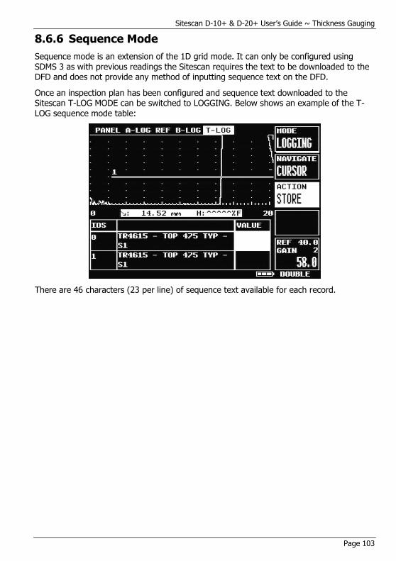
Sitescan D-10+ & D-20+ User’s Guide ~ Thickness Gauging
Page 103
8.6.6 Sequence Mode
Sequence mode is an extension of the 1D grid mode. It can only be configured using
SDMS 3 as with previous readings the Sitescan requires the text to be downloaded to the DFD and does not provide any method of inputting sequence text on the DFD.
Once an inspection plan has been configured and sequence text downloaded to the Sitescan T-LOG MODE can be switched to LOGGING. Below shows an example of the T-LOG sequence mode table:
There are 46 characters (23 per line) of sequence text available for each record.

Sitescan D-10+ & D-20+ User’s Guide ~ Thickness Gauging
Page 104
8.6.7 Customised Row / Column Titles
Using SDMS 3 it is possible to download customised column titles to the Sitescan DFD. In
2D grid mode, a set of row and column titles can be downloaded and displayed each title can be a maximum of five characters long.
This feature enables an operator to achieve a closer relationship between the physical inspection plan and the standard grid layouts common with Thickness Gauges.
Sitescan D-10+ & D-20+ User’s Guide ~ Thickness Gauging
Page 105
9 Upgrading to Version 3 Software In order to upgrade a Sitescan D-10+ or D-20+ to software version 3.x.x, the following must be taken into consideration.
9.1 FPGA Version:
If the FPGA Version is lower than 9 – DO NOT INSTALL V3.x.x software. Installing V3.0.0 will cause the set to fail to boot and give ‘snowy screen’. DFD will need to be returned for repair (NMI Reset).
If the FPGA Version is higher than 9 but lower than 12 – V3.x.x software can be installed BUT the BSCAN option and the new FLANK-FLANK MEAS option will not be available. It will also not be possible to recall A-Logs. Installing V3.x.x will cause warning message, BSCAN and FLANK-FLANK Meas mode will be locked out. A-LOG and REF menus will be disabled.
If the FPGA Version is 12 – V3.x.x software can be installed BUT it will not be possible to recall A-Logs. Installing V3.x.x will cause a warning message; A-LOG and REF menus will be disabled.
If the FPGA Version is 13 or higher everything will work as expected.
9.2 Memory Stores:
Version 3.x.x software is required to format the memory store in order to allow access to the extended memory. This means that all stores will be cleared – all panels, A-Logs and T-Logs.
When installing software version 3.0.0 or above for the first time you must be aware that the DFD’s internal memory must be wiped and formatted.
Before updating the unit you must save any information from the Sitescan D-10+ or D-20+ onto a PC using SDMS that you wish to keep.
Once software version 3.0.0 or higher has been installed it will then be possible to enter your license key for the Advanced Thickness option. Upon entering your license key 2 new menus will appear - BSCAN (under menu group MEAS) and B-LOG (under menu group MEMORY). Some other internal adjustments will occur to enable the locked options.
It is important that you wait for a couple of minutes after the set boots up for the first time with version 3.x.x installed for the memory to be formatted before switching off the unit or attempting to store anything.

Sitescan D-10+ & D-20+ User’s Guide ~ Upgrading to Version 3 Software
Page 106
10 Battery The Sitescan D-10+ & D-20+ is powered by a Lithium-Ion battery pack, which is shown below. The battery pack attaches to the rear of the Sitescan D-10+ & D-20+ by locating the prong in the recess in the battery compartment and then hinge the battery into position and secure using the thumb screw. The battery connects to the instrument via two terminal contact points.
10.1 Battery Cautions
Misuse of Lithium-ion batteries may result in the following hazards: smoke, fire, or battery
rupture. Misuse can also cause other battery damage or degradation of battery performance
DANGER! Use and charge only the specified Sonatest battery pack with the Sitescan D-10+ & D-20+. Only the Sonatest battery pack is tested and approved for use with the Sitescan D-10+ & D-20+. Using third-party or counterfeit battery packs may cause smoke, fire, or cause the battery to burst.
DANGER! DO NOT hammer or otherwise impact the battery. Do not use the battery if it has been severely impacted or dropped, or if the battery has been subjected to heavy pressure. Battery damage may not be visible on the outside of the case. Even if the surface of the battery does not show cracks or any other damage, the cells inside the battery may rupture or catch fire.
DANGER! NEVER use or leave battery pack in areas with temperatures above +60°C. High temperature build-up in the battery, such as could occur near fires or stoves, inside a sun-heated car, or by setting the battery in direct sunlight may cause the battery to rupture or catch fire. Excessive temperatures may also degrade battery performance or shorten battery life.
Sitescan D-10+ & D-20+ User’s Guide ~ Battery
Page 107
DANGER! DO NOT charge or use a wet battery. If the battery gets wet, be sure to wipe it dry before using.
DANGER! NEVER incinerate a used battery pack since internal battery gas may cause a rupture or explosion.
DANGER! NEVER solder the battery terminals, or modify the battery pack. This may cause heat generation, and the battery may rupture, emit smoke or catch fire.
DANGER! Use the battery only with the Sitescan D-10+ & D-20+ for which it is specified. Never use a battery with any other equipment, or for any purpose that is not specified in this instruction manual.
DANGER! If fluid from inside the battery gets in your eyes, blindness can result. Rinse your eyes with clean water, without rubbing them, and see a doctor immediately.
WARNING! Immediately stop using the battery if it emits an abnormal odour, heats up, or is discoloured or deformed. If any of these conditions occur, contact Sonatest.
WARNING! Immediately wash, using clean water, any part of the body that comes into contact with fluid from inside the battery.
WARNING! NEVER put the battery in a microwave oven, high-pressure container, or in an induction heating cooker. This could cause overheating, a fire, or cause the battery to rupture.
• CAUTION! Always use the battery within the specified temperature range for the Sitescan D-10+ & D-20+ (-10°C to +55°C) and the battery itself (-20°C to +60°C). Using the battery out of its specified temperature range will reduce the battery's performance and battery life. Please note that the specified temperature range of the battery may exceed that of the Sitescan D-10+ & D-20+. In such cases, the Sitescan D-10+ & D-20+ may not work properly because it is out of its operating temperature range.
• CAUTION! Shorter battery life could occur if the battery is left fully charged, completely discharged, or in an excessive temperature environment (above +45°C) for an extended period of time. If the battery must be left unused for a long time, it must be detached from the Sitescan D-10+ & D-20+ after discharging. You may use the battery until the battery indicator shows half-capacity, and then keep it safely in a cool dry place with the temperature between -20°C to +25°C. If the battery pack is not going to be used for a long time it must be periodically charged every 4 months; failure to do so will render the battery inoperable and it will need to be returned to Sonatest for re-charging. If a number of spare battery packs are in use the easiest way to maintain optimum conditions is to rotate the battery packs so that when one is discharged it is swapped with a fully charged one.
Sitescan D-10+ & D-20+ User’s Guide ~ Upgrading to Version 3 Software
Page 108
10.2 Battery Charging
Charging Caution
DANGER! Only use the CH700-P charger to charge the battery. Using any other charger may cause smoke, fire, or cause the battery to burst.
DANGER! NEVER charge the battery pack in areas with extremely high temperatures, such as near fires or stoves, inside a sun-heated car, or in direct sunlight. In such environments, the safety/protection circuit in the battery will activate, causing the battery to stop charging.
WARNING! DO NOT charge or leave the battery in the battery charger beyond the specified time for charging. If the battery is not completely charged by the specified time, stop charging and remove the battery from the battery charger. Continuing to charge the battery beyond the specified time limit may cause a fire, overheating, or the battery may rupture.
WARNING! NEVER insert the battery charger into the Sitescan D-10+ & D-20+ or battery if it is wet or soiled. This could corrode the battery charger terminals or damage the charger. The charger is not waterproof.
• CAUTION! DO NOT charge the battery outside of the specified temperature range: 0°C to +40°C. Sonatest recommends charging the battery at +20°C. The battery may heat up or rupture if charged out of the specified temperature range. Additionally, battery performance or battery life may be reduced.
When fully charged, the battery pack should enable the unit to be operated for 19 hours
when the brightness is at level 1 in the VIDEO menu under UTIL, for 12½ hours with a
brightness of 10 (the default) or for 9 hours with a brightness of 20. The battery pack can be charged while mounted to the Sitescan D-10+ & D-20+. Alternately, the battery pack can be charged separate from the Sitescan D-10+ & D-20+ allowing continued operation of the Sitescan D-10+ & D-20+ with the use of multiple battery packs.
When shipped the battery has only a nominal charge and must be fully charged before being used for the first time.
The Sonatest CH700-P battery charger shown below is suitable for use with main supply from 100 to 240 volts AC with a frequency of 50-60Hz. The LED on the charger illuminates to indicate power on. When the battery level is low the LED will glow red. When the battery level is almost full the LED will glow yellow. When the battery level is full the LED glows green. The output voltage from the charger is 16.4 Volts DC. The output current when charging is a constant 2.0 Amps. The part number for a battery pack is Y-04.
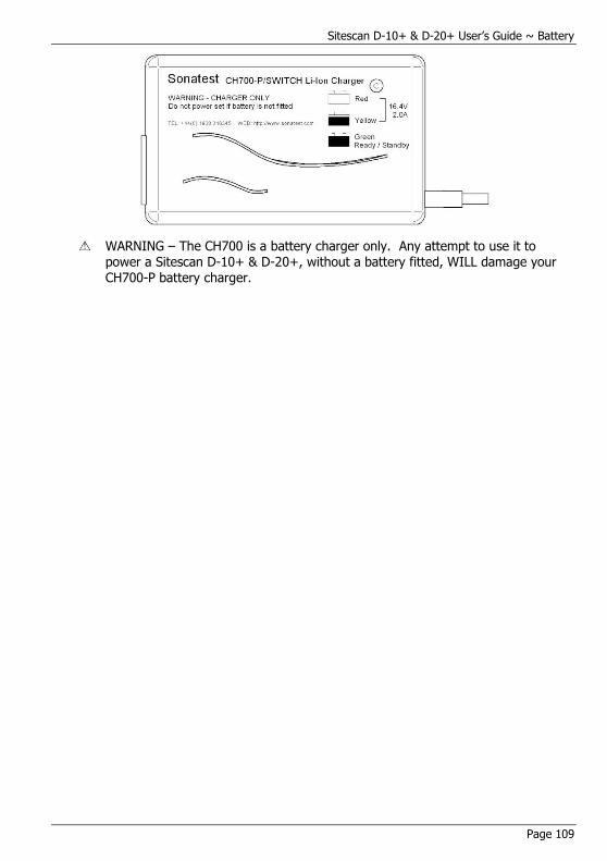
Sitescan D-10+ & D-20+ User’s Guide ~ Battery
Page 109
WARNING – The CH700 is a battery charger only. Any attempt to use it to power a Sitescan D-10+ & D-20+, without a battery fitted, WILL damage your CH700-P battery charger.
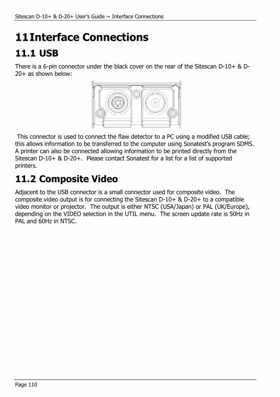
Sitescan D-10+ & D-20+ User’s Guide ~ Interface Connections
Page 110
11 Interface Connections
11.1 USB
There is a 6-pin connector under the black cover on the rear of the Sitescan D-10+ & D-20+ as shown below:
This connector is used to connect the flaw detector to a PC using a modified USB cable; this allows information to be transferred to the computer using Sonatest’s program SDMS. A printer can also be connected allowing information to be printed directly from the Sitescan D-10+ & D-20+. Please contact Sonatest for a list for a list of supported printers.
11.2 Composite Video
Adjacent to the USB connector is a small connector used for composite video. The composite video output is for connecting the Sitescan D-10+ & D-20+ to a compatible video monitor or projector. The output is either NTSC (USA/Japan) or PAL (UK/Europe), depending on the VIDEO selection in the UTIL menu. The screen update rate is 50Hz in PAL and 60Hz in NTSC.
Sitescan D-10+ & D-20+ User’s Guide ~ Interface Connections
Page 111
12 Features of the Sitescan D-10+ & D-20+ The Sitescan D-10+ & D-20+ is a user-friendly ultrasonic digital flaw detector and thickness gauge, which is simple to use and provides the experienced ultrasonic operator with a full-function device that incorporates many productivity enhancing features. All of the features of the Sitescan D-10+ & D-20+ are accessed through a menu system using the front panel keypad.
Functional Testing Methods
The Sitescan D-10+ & D-20+ supports the following ultrasonic testing methods:
Pulse-Echo Flaw Detection
Transmit-Receive Flaw Detection
Time of flight measurement
Contact or Immersion Methods
Angle Beam (Shear Wave) Testing
Angle Beam (Surface Wave) Testing
Crack Diffraction Methods
Depth of Flaw Measurement
Single Transducer Thickness Measurement
Dual Transducer Thickness Measurement
Indirect Measurement of Sound Velocity in Materials
Phase change display in un-rectified mode
Through transmission testing
Creep wave testing
Pitch and catch techniques

Sitescan D-10+ & D-20+ User’s Guide ~ Specifications
Page 112
13 Specifications
Feature Details Test Range 0 - 5mm (0.2in) up to 0 – 5,000 mm (200 in.) at steel velocity.
Variable in 1mm &10mm steps
Velocity 1,000 to 9,999m/s continuously variable.
Probe Zero 0 to 999.999 μs, continuously variable.
Delay Calibrated delay from 0 - 5,000mm in 0.05 mm steps at steel velocity (0-400in. in 0.002 in. steps).
Gain 0 to 110dB. Adjustable in 0.5, 1, 2, 6, 10, 14 and 20dB steps. Direct access to gain control at all times.
Test Modes Pulse echo and transmit/receive.
Pulser -200V square wave pulser. Pulse width from 30 to 250ns duration
linked to filter band. rise/fall times <10ns into 50 ohms
P.R.F Selectable 35 to 1,000 Hz in 5 Hz steps
Update Rate 60Hz (NTSC Mode); 50Hz (PAL Mode).
Rectification Full wave, positive or negative halfwave and unrectified rf.
Frequency Range 3 narrow bands centred at1MHz, 2.25MHz and 5MHz (D-20+ Only) 10MHz. Broad band at 1.5 MHz to 15MHz (-6dB).
System Linearity Vertical = 1% Full Screen Height (FSH). Amplifier Accuracy ± 0.1dB. Horizontal ±0.4% Full Screen Width (FSW).
Reject 50% supressive reject. LED warning light when selected.
Units Metric (mm) or inch (in)
Display Colour Transflective TFT
Display area 116.16 x 87.12 mm (4.57 x 3.43 in) 640 x 480 pixels. A-Scan Area 510 x 400 pixels (610 x 400 expanded), 8 colour options and variable brightness.
Gate Monitor Two fully independent gates for echo monitoring and thickness measurement. Start and width adjustable over full range of unit, amplitude variable from 0 to 100% FSH. Bar presentation. Positive or negative triggering for each gate with audible and visual alarms.
Gate Expansion Expands range to width of Gate 1.
Measurement Modes Mode 1 Signal Monitor
Mode 2 Depth and amplitude of first signal in gate.
Mode 3 Echo-to-Echo distance measurement. (single gate)
Mode 4 Trigonometric display of beam path, surface distance and depth of indication, curve surface correction and X-OFFSET for probe index. Half skip indication on screen.
Mode 5 Gate to Gate distance measurement. (Independent gates). (Option)
Mode 6 T-Min mode for holding minimum thickness reading.
Resolution 0.01mm (0.001in) for distance measurement or 1% FSH for amplitude measurement. Large display of measurement at top of A-Scan display. Measurement mode selectable between peak and
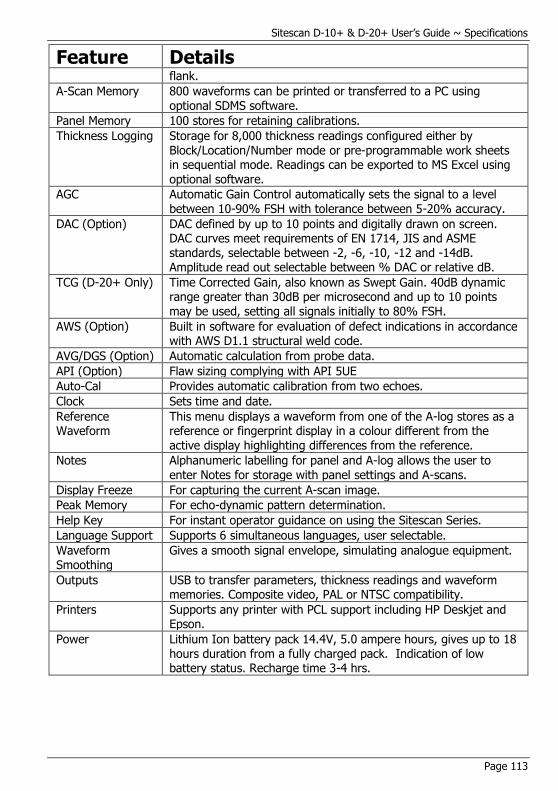
Sitescan D-10+ & D-20+ User’s Guide ~ Specifications
Page 113
Feature Details flank.
A-Scan Memory 800 waveforms can be printed or transferred to a PC using optional SDMS software.
Panel Memory 100 stores for retaining calibrations.
Thickness Logging Storage for 8,000 thickness readings configured either by Block/Location/Number mode or pre-programmable work sheets in sequential mode. Readings can be exported to MS Excel using optional software.
AGC Automatic Gain Control automatically sets the signal to a level between 10-90% FSH with tolerance between 5-20% accuracy.
DAC (Option) DAC defined by up to 10 points and digitally drawn on screen. DAC curves meet requirements of EN 1714, JIS and ASME standards, selectable between -2, -6, -10, -12 and -14dB. Amplitude read out selectable between % DAC or relative dB.
TCG (D-20+ Only) Time Corrected Gain, also known as Swept Gain. 40dB dynamic range greater than 30dB per microsecond and up to 10 points may be used, setting all signals initially to 80% FSH.
AWS (Option) Built in software for evaluation of defect indications in accordance with AWS D1.1 structural weld code.
AVG/DGS (Option) Automatic calculation from probe data.
API (Option) Flaw sizing complying with API 5UE
Auto-Cal Provides automatic calibration from two echoes.
Clock Sets time and date.
Reference Waveform
This menu displays a waveform from one of the A-log stores as a reference or fingerprint display in a colour different from the
active display highlighting differences from the reference.
Notes Alphanumeric labelling for panel and A-log allows the user to enter Notes for storage with panel settings and A-scans.
Display Freeze For capturing the current A-scan image.
Peak Memory For echo-dynamic pattern determination.
Help Key For instant operator guidance on using the Sitescan Series.
Language Support Supports 6 simultaneous languages, user selectable.
Waveform Smoothing
Gives a smooth signal envelope, simulating analogue equipment.
Outputs USB to transfer parameters, thickness readings and waveform memories. Composite video, PAL or NTSC compatibility.
Printers Supports any printer with PCL support including HP Deskjet and Epson.
Power Lithium Ion battery pack 14.4V, 5.0 ampere hours, gives up to 18 hours duration from a fully charged pack. Indication of low battery status. Recharge time 3-4 hrs.
Sitescan D-10+ & D-20+ User’s Guide ~ Warranty
Page 114
14 Warranty Warranty/Defects after Delivery: Immediately upon receipt of the goods the buyer is required to check the goods carefully and thoroughly. In order to benefit from the guarantee, any defect in the product should be immediately reported in writing to Sonatest. Sonatest will make good by repair or by the supply of a replacement or by equivalent adjustment of the price at our sole option, any defects which under proper use appear in the goods within the period of twelve (12) calendar months after the goods have been delivered and which arise solely from faulty design, material or workmanship, provided that the goods are carefully packed and promptly returned by you, free of charge, to the Sonatest works unless otherwise arranged. Said goods should be covered while in transit to us and must be accompanied by a written statement detailing the precise nature of the fault and the operating conditions under which the fault occurred. The repaired goods will be returned by Sonatest free of charge.
Save as in this Clause herein before expressed Sonatest shall not be under any liability in respect of defects in goods delivered or for any injury damage or loss resulting from such defects and our liability under this Clause shall be in lieu of any warranty or condition implied by law as to the quality, fitness or merchantability for any particular purpose of such goods.

Sitescan D-10+ & D-20+ User’s Guide ~ Warranty
Page 115
Index
A
Adjustment · 67 AGC · 19, 23, 26, 69, 113
AGC (Automatic Gain Control) · 26 A-Log · 1, 19, 33, 34, 35, 38, 39,
43, 50, 80, 81, 82, 83, 84, 91,
105 A-Scan Storage · 1, 34, 50, 80, 84
Memory Menu · 34 American Welding Society · 29, 56
Amplifier · 20, 27, 48, 88, 112 Amplifier Menu · 20
angle · 9, 23, 24, 47, 50, 62, 63, 65,
70, 71, 83 Angle · 69, 111
API · 30, 39, 56, 59, 60, 61, 69, 113 Menu · 30
A-Scan · 1, 9, 10, 15, 23, 33, 34, 38, 50, 73, 74, 80, 81, 82, 84, 85,
86, 92, 95, 98, 99, 112, 113
Attenuation · 28, 31, 47, 51, 53, 57, 62, 64, 87, 91
AVG · 31, 56, 62, 63, 67, 69, 113 AWS · 29, 39, 56, 57, 58, 69, 113
AWS Menu · 29
B
Backwall · 48, 65, 78
Basic Flaw Testing · 47 Basic Thickness Gauging · 87
Battery · 1, 15, 37, 106, 107, 108, 109, 113
Battery Charging · 108 Beam · 4, 9, 23, 24, 25, 47, 50, 51,
53, 56, 62, 70, 71, 75, 76, 83, 87,
111, 112
Beam Path Distance · 23, 25, 70
Blank · 86 Block · 4, 13, 14, 22, 25, 31, 47, 48,
62, 63, 64, 65, 66, 71, 75, 87, 88,
99, 113 BNC · 11
Broad Band · 112
C
CAL · 8, 13, 14, 19, 20, 22, 25, 30, 48, 49, 56, 59, 69, 71, 75, 88, 90,
91, 95, 99 Menu · 20
Calibration · 1, 4, 5, 7, 11, 13, 14,
15, 19, 20, 22, 25, 30, 31, 33, 38, 41, 43, 47, 48, 49, 51, 53, 60, 63,
64, 65, 66, 67, 71, 74, 75, 76, 78, 80, 87, 88, 90, 91, 95, 99, 113
Calibration Menu · 20 Calibration of the Sound Velocity · 4
Centre Frequency · 20
Certification · 3 Charge · 106, 107, 108, 114
Charger · 108, 109 Clearing the Memory · 15
Click · 38, 39
Clock · 19, 39, 113 CLOCK Menu · 39
Composite Video · 37, 110, 113 Concave · 24
Connector · 11, 110
Contact · 6, 47, 48, 87, 106, 107, 110, 111
Contents · ii Contour · 69
Controls · 33, 34, 35, 37 Convex · 24
Corrosion · 87
Couplant · 5
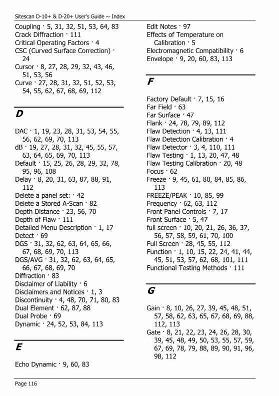
Sitescan D-10+ & D-20+ User’s Guide ~ Index
Page 116
Coupling · 5, 31, 32, 51, 53, 64, 83
Crack Diffraction · 111
Critical Operating Factors · 4 CSC (Curved Surface Correction) ·
24 Cursor · 8, 27, 28, 29, 32, 43, 46,
51, 53, 56 Curve · 27, 28, 31, 32, 51, 52, 53,
54, 55, 62, 67, 68, 69, 112
D
DAC · 1, 19, 23, 28, 31, 53, 54, 55,
56, 62, 69, 70, 113 dB · 19, 27, 28, 31, 32, 45, 55, 57,
63, 64, 65, 69, 70, 113 Default · 15, 25, 26, 28, 29, 32, 78,
95, 96, 108 Delay · 8, 20, 31, 63, 87, 88, 91,
112
Delete a panel set: · 42 Delete a Stored A-Scan · 82
Depth Distance · 23, 56, 70 Depth of Flaw · 111
Detailed Menu Description · 1, 17
Detect · 69 DGS · 31, 32, 62, 63, 64, 65, 66,
67, 68, 69, 70, 113 DGS/AVG · 31, 32, 62, 63, 64, 65,
66, 67, 68, 69, 70 Diffraction · 83
Disclaimer of Liability · 6
Disclaimers and Notices · 1, 3 Discontinuity · 4, 48, 70, 71, 80, 83
Dual Element · 62, 87, 88 Dual Probe · 69
Dynamic · 24, 52, 53, 84, 113
E
Echo Dynamic · 9, 60, 83
Edit Notes · 97
Effects of Temperature on
Calibration · 5 Electromagnetic Compatibility · 6
Envelope · 9, 20, 60, 83, 113
F
Factory Default · 7, 15, 16 Far Field · 63
Far Surface · 47 Flank · 24, 78, 79, 89, 112
Flaw Detection · 4, 13, 111
Flaw Detection Calibration · 4 Flaw Detector · 3, 4, 110, 111
Flaw Testing · 1, 13, 20, 47, 48 Flaw Testing Calibration · 20, 48
Focus · 62 Freeze · 9, 45, 61, 80, 84, 85, 86,
113
FREEZE/PEAK · 10, 85, 99 Frequency · 62, 63, 112
Front Panel Controls · 7, 17 Front Surface · 5, 47
full screen · 10, 20, 21, 26, 36, 37,
56, 57, 58, 59, 61, 70, 100 Full Screen · 28, 45, 55, 112
Function · 1, 10, 15, 22, 24, 41, 44, 45, 51, 53, 57, 62, 68, 101, 111
Functional Testing Methods · 111
G
Gain · 8, 10, 26, 27, 39, 45, 48, 51, 57, 58, 62, 63, 65, 67, 68, 69, 88,
112, 113
Gate · 8, 21, 22, 23, 24, 26, 28, 30, 39, 45, 48, 49, 50, 53, 55, 57, 59,
67, 69, 78, 79, 88, 89, 90, 91, 96, 98, 112

Sitescan D-10+ & D-20+ User’s Guide ~ Warranty
Page 117
Gate 1 · 13, 14, 19, 21, 48, 49, 50,
59, 88, 90
Gate 2 · 21 Gates · 21, 23, 79, 112
General Warnings · 3 Ghosting · 21
H
Hardcopy · 80
Help · 7, 11, 43, 45, 113 HUD · 13, 14, 23, 25, 39, 57, 58,
61, 76, 88
I
Immersion · 111 Included Angle · 87
Interface Connections · 1, 110
L
LEMO · 11 Level · 20, 21, 23, 26, 28, 29, 30,
37, 56, 57, 67, 78, 79, 108, 113
Location · 34, 41, 43, 70, 80, 85, 98, 102, 113
Longitudinal · 87
M
Main Menu · 19 Main Menu Selection · 19
MEAS · 8, 13, 14, 19, 23, 24, 26,
27, 28, 30, 48, 49, 51, 53, 54, 55, 56, 59, 60, 71, 72, 75, 88, 89, 90,
101, 105 MEAS Menu · 23
Measurement · 1, 19, 21, 23, 24,
25, 26, 28, 29, 30, 32, 37, 38, 49,
57, 60, 61, 62, 67, 68, 69, 70, 72, 75, 76, 78, 79, 86, 88, 89, 101,
111, 112 Measurement Menu · 19, 23
Memory · 1, 8, 15, 16, 19, 33, 34, 35, 38, 41, 80, 81, 82, 85, 93, 97,
105, 113
Menu Tree · 17 Metric · 14, 15, 16, 25, 112
Microseconds · 20 MISC · 19, 38
MISC Menu · 38
Mode · 3, 8, 9, 10, 11, 13, 14, 20, 21, 23, 24, 25, 26, 27, 28, 29, 30,
31, 32, 36, 38, 39, 45, 46, 51, 52, 53, 54, 56, 57, 58, 60, 61, 69, 70,
71, 72, 73, 74, 75, 76, 78, 79, 81, 83, 84, 85, 86, 88, 89, 92, 93, 94,
95, 96, 97, 98, 99, 100, 103, 104,
105, 111,112, 113 Mode Conversion · 3
Multiple Echo · 88, 89
N
Near Field · 4, 31, 62, 63 Notes · 33, 34, 35, 38, 41, 42, 43,
44, 80, 81, 85, 86, 92, 94, 96, 99, 100, 113
Notes Window · 43
NTSC · 37, 110, 112, 113
O
Operator Training · 3 Orientation · 4, 47
Outputs · 113
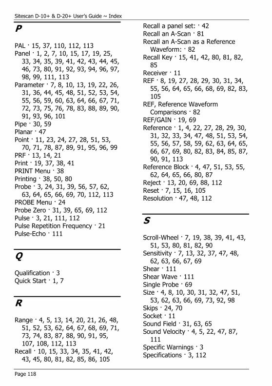
Sitescan D-10+ & D-20+ User’s Guide ~ Index
Page 118
P
PAL · 15, 37, 110, 112, 113 Panel · 1, 2, 7, 10, 15, 17, 19, 25,
33, 34, 35, 39, 41, 42, 43, 44, 45, 46, 73, 80, 91, 92, 93, 94, 96, 97,
98, 99, 111, 113
Parameter · 7, 8, 10, 13, 19, 22, 26, 31, 36, 44, 45, 48, 51, 52, 53, 54,
55, 56, 59, 60, 63, 64, 66, 67, 71, 72, 73, 75, 76, 78, 83, 88, 89, 90,
91, 93, 96, 101
Pipe · 30, 59 Planar · 47
Point · 11, 23, 24, 27, 28, 51, 53, 70, 71, 78, 87, 89, 91, 95, 96, 99
PRF · 13, 14, 21 Print · 19, 37, 38, 41
PRINT Menu · 38
Printing · 38, 50, 80 Probe · 3, 24, 31, 39, 56, 57, 62,
63, 64, 65, 66, 69, 70, 112, 113 PROBE Menu · 24
Probe Zero · 31, 39, 65, 69, 112
Pulse · 3, 21, 111, 112 Pulse Repetition Frequency · 21
Pulse-Echo · 111
Q
Qualification · 3 Quick Start · 1, 7
R
Range · 4, 5, 13, 14, 20, 21, 26, 48,
51, 52, 53, 62, 64, 67, 68, 69, 71, 73, 74, 83, 87, 88, 90, 91, 95,
107, 108, 112, 113 Recall · 10, 15, 33, 34, 35, 41, 42,
43, 45, 80, 81, 82, 85, 86, 105
Recall a panel set: · 42
Recall an A-Scan · 81
Recall an A-Scan as a Reference Waveform: · 82
Recall Key · 15, 41, 42, 80, 81, 82, 85
Receiver · 11 REF · 8, 19, 27, 28, 29, 30, 31, 34,
55, 56, 64, 65, 66, 68, 69, 82, 83,
105 REF, Reference Waveform
Comparisons · 82 REF/GAIN · 19, 69
Reference · 1, 4, 22, 27, 28, 29, 30,
31, 32, 33, 34, 47, 48, 51, 53, 54, 55, 56, 57, 58, 59, 62, 63, 64, 65,
66, 67, 69, 80, 82, 83, 84, 85, 87, 90, 91, 113
Reference Block · 4, 47, 51, 53, 55, 62, 64, 65, 66, 80, 87
Reject · 13, 20, 69, 88, 112
Reset · 7, 15, 16, 105 Resolution · 47, 48, 112
S
Scroll-Wheel · 7, 19, 38, 39, 41, 43,
51, 53, 80, 81, 82, 90 Sensitivity · 7, 13, 32, 37, 47, 48,
62, 63, 66, 67, 69 Shear · 111
Shear Wave · 111
Single Probe · 69 Size · 4, 8, 10, 30, 31, 32, 47, 51,
53, 62, 63, 66, 69, 73, 92, 98 Skips · 24, 70
Socket · 11
Sound Field · 31, 63, 65 Sound Velocity · 4, 5, 22, 47, 87,
111 Specific Warnings · 3
Specifications · 3, 112
Sitescan D-10+ & D-20+ User’s Guide ~ Warranty
Page 119
Start · 15, 21, 22, 23, 30, 78, 89,
90, 112
State · 21, 98 Storage · 1, 15, 33, 35, 41, 85, 113
Storage & Recall of Calibration Setups · 15, 33, 41
Store · 15, 33, 34, 35, 36, 41, 42, 43, 80, 82, 85, 86, 92, 95, 96, 97,
98, 99, 101, 105
Store a panel set · 41 Store An A-Scan · 80
Surface · 4, 23, 24, 26, 31, 32, 47, 48, 56, 62, 64, 65, 70, 73, 74, 83,
85, 87, 106, 111, 112
Surface Wave · 47, 111
T
TCG · 1, 19, 23, 27, 31, 51, 52, 53,
56, 62, 91, 113
Temperature · 5, 25, 75, 76, 106, 107, 108
Temperature Variations · 5 Test Blocks · 4, 5, 56, 87, 90
Testing Limitations · 4
T-FN · 19 Theory · 62
Thickness Gauge · 3, 104, 111 Thickness Gauging · 1, 14, 87, 89
Threshold · 21, 23, 28, 53, 91 Time Corrected Gain · 27, 51, 53,
91, 113
Time of Flight · 4, 59, 75, 111 Time-of-Flight · 90
T-Log · 36, 105 T-Min · 112
Training · 3
Transducer (Probe) Zero Procedure · 4
Transducer Condition · 5 Transmit-Receive · 111
Transmitter · 11
Trigger · 8, 55, 78
Trigonometric · 24, 75, 112
Twin · 11, 21 TX · 13, 14, 19, 21, 45, 48, 88
Typographical Conventions · 2
U
Ultrasonic · 1, 3, 4, 5, 6, 17, 30, 59, 62, 71, 87, 90, 91, 111
Ultrasonic Testing · 1, 3, 4, 6, 17, 90, 111
Unrectified · 112
USB · 11, 38, 44, 110, 113 Use of Couplant · 5
User Keys · 10, 19, 37, 39, 45, 101 Using the Optional Keyboard · 44
UTIL · 8, 13, 14, 19, 20, 37, 45, 108, 110
Utilities · 19
V
Valid · 38, 61, 62, 80, 95
Velocity · 3, 4, 13, 14, 20, 31, 49, 62, 63, 64, 65, 66, 71, 75, 87, 90,
91, 112 Velocity of Sound · 3, 20, 49, 71,
90, 91 Video · 15, 19, 37, 108, 110
VIDEO Menu · 37
W
Warranty · 114
Wave · 3, 20, 39, 59, 63, 69, 111, 112
Wavelength · 47, 62, 64, 66, 87 Wedge · 63, 65, 75
Sitescan D-10+ & D-20+ User’s Guide ~ Index
Page 120
Weld · 23, 29, 47, 50, 56, 70, 83,
113
Weld Inspection · 23, 29, 47, 50, 56, 70, 83
Weld Inspection Using the AWS Menu · 29, 56
Weld Inspection Using Trigonometry Mode · 47, 50, 56, 70
Width · 3, 20, 21, 22, 28, 29, 32,
63, 73, 78, 83, 90, 112
Z
Zero · 4, 8, 20, 22, 63, 66, 69, 71, 87, 90, 91