Embed Size (px)
Citation preview

SIT - ELECTRICAL AND ELECTRONICS ENGINEERING E – SCHEME w.e.f 2016 – 2017
------------------------------------------------------------------------------------------------------------------------------
1
PREFACE
The wave of liberalization and globalization has created an environment for free flow
of information and technology through fast and efficient means the world over. This has
lead to shrinking of world, bringing people from different cultures and environment
together, giving rise to a global village. A shift has been taking place in India from closed
economy to knowledge based and open economy. In order to cope-up with the challenges of
handling new technologies, materials and methods, we have to develop human resources
having appropriate knowledge, professional skills and attitude. Technical education system
is one of the significant components for human resource development. Polytechnics play
an important role in meeting the requirements of trained technical manpower for industries
and field organizations. The initiatives being taken by the State Board of Technical
Education, Tamilnadu to revise the curriculum of existing diploma programmes as per the
needs of the industry are laudable.
In order to meet the requirements of future technical manpower, constant efforts have
to be made to identify new employment opportunities, carryout activity analysis and design
need based curricula of diploma programmes. This curriculum document has been designed
by identifying job potential and competency profile of diploma holders leading to
identification of curriculum areas for the course.
It is needless to emphasize that the real success of the diploma programme depends
upon its effective implementation. This will require harnessing and effective utilization of
resources. In addition to acquisition of appropriate physical resources, the availability of
competent and qualified faculty is essential.
It is time for the managers of technical education system to reorganize the system to
accept the challenges of both quantitative and qualitative expansion of technical education.
The creation of EDUSAT facilities in the country must be exploited to its fullest extent to
reap the benefits of interactive electronic media for teaching-learning process.
It is hoped that polytechnics will carry out job market research on a continuous basis to
identify the new skill requirements and develop innovative methods of course offering and
thereby infuse dynamism in the system.
Principal
Seshasayee Institute of Technology

SIT - ELECTRICAL AND ELECTRONICS ENGINEERING E – SCHEME w.e.f 2016 – 2017
------------------------------------------------------------------------------------------------------------------------------
2
ACKNOWLEDGEMENT
We gratefully acknowledge the assistance and guidance received from the following
persons:
i) Commissioner Technical Education and Special Officer Curriculum Development centre,
DOTE, Chennai for taking keen interest and support in the design of this curriculum.
ii) Academic Board Members
Thiru.G.M.Rajendran, GM (Retd)/ BHEL, Trichy
Dr D.Brahadeeswaran, Professor(Retd), NITTR, Chennai
Tmt.J.Rama, Regional Officer-IV, DOTE, Chennai
Thiru.S.Muruganantham, Principal GPT, Srirangam
Dr.P.Sakthivel, Associate Professor, College of Engineering, Guindy, Chennai
Thiru.P.Srinivasan,Senior Engineer IT, Golden Rock, Trichy
for their suggestions and guidance in execution of the Curriculum and syllabus
iii) Programme Advisory Committee members :
Dr. S.Arul Daniel, Professor / EEE, NIT, Trichy
Dr. G.Balamurali, Assistant Executive Engineer / TANGEDCO, Chennai
Thiru. J.Sathiya Narayanan, Senior Section Engineer, Southern Railway, Trichy,
Thiru. T.Selvakumar, Lecturer(SG) / EEE, Government Polytechnic College, Trichy
for their professional inputs and guidance in execution of the Curriculum and syllabus.
iv) Principal of this Institute for his Guidance and Academic freedom provided to the
Department in design of this curriculum.
v) All the faculty members from Department of Electrical and Electronics Engineering
for their untiring assistance and support in curriculum design workshops.
Coordinator

SIT - ELECTRICAL AND ELECTRONICS ENGINEERING E – SCHEME w.e.f 2016 – 2017
------------------------------------------------------------------------------------------------------------------------------
3
CONTENTS
Sl. No Particulars PageNo
1 Department Vision, Mission, PEO and PO 4
2 Rules and Regulations 5
3 Salient Features of the Diploma Programme 12
4 Employment Opportunities for Diploma Holders in Electrical
and Electronics Engineering 13
5 Competency Profile of Diploma holders in Electrical and
Electronics Engineering 16
6 Deriving Curriculum Areas from Competency Profile 18
7 Curriculum Outline 21
8 Horizontal and Vertical Organisation of the Courses 25
9 Detailed Content of various Courses 27
10 Model Question Papers 151
11 Equivalent Papers 188

SIT - ELECTRICAL AND ELECTRONICS ENGINEERING E – SCHEME w.e.f 2016 – 2017
------------------------------------------------------------------------------------------------------------------------------
4
1. Department Vision, Mission, PEO and PO
Vision
To meet the challenges of new technological advances and to provide update knowledge in the
state of the art technology, re-orientation and up gradation of the curriculum to the level of
industry relevant learning and training and thus to be a premier technical department that strives
continuously for excellence in education
Mission
To produce Electrical Engineers of high Caliber to serve the Society and Nation.
To bridge the gap between industry and academic by framing curriculum and syllabus
based on industrial needs
To create and sustain environment of learning in which students acquire knowledge and
learn to apply it professionally with due consideration of social and economical issues.
To provide opportunity to enhance the creative talents of students and faculty members
To inculcate moral and ethical values among the faculty and students
PROGRAMME EDUCATIONAL OBJECTIVES (PEOs)
Electrical and Electronics Engineering programme of Seshasayee Institute of Technology
will prepare its diploma students
PEO1: To have fundamental and broad knowledge in Electrical and Electronics Engineering
PEO2: To apply creatively their understanding of engineering principles to the solution of
problems arising in whatever career they choose
PEO3: To communicate their ideas and positions clearly and concisely
PEO4: To practice their Professions conforming to Ethical Values and Environmental friendly
policies
PEO5: To work as a team in multi-cultural and multi-disciplinary Environments
PEO6: To adapt evolving Technologies, innovations and stay current with their Professions
PROGRAMME OUTCOMES (POs)
Students of Diploma in Electrical and Electronics Engineering course at our institute will be
PO1: Able to identify, analyze and provide solutions to problems in the field of Electrical and
Electronic Engineering
PO2: Able to adopt energy conservation and renewable energy in order to promote eco-friendly
electrical energy production
PO3: Able to communicate effectively in order to compete globally
PO4: Able to handle any situation with ethical and social responsibility
PO5: Able to work as an individual and as a team member in multi-cultural and multi-
disciplinary Environments
PO6: Able to apply modern techniques and IT tools in Engineering
SIT - ELECTRICAL AND ELECTRONICS ENGINEERING E – SCHEME w.e.f 2016 – 2017
------------------------------------------------------------------------------------------------------------------------------
5
2. R U L E S & R E G U L A T I O N S
DIPLOMA COURSES IN ENGINEERING
(TERM PATTERN)
(Implemented from 2016- 2017)
E – SCHEME
(Common to all Programmes)
1. Description of the Programme:
a. Full Time (3 years)
The Programme for the Full Time Diploma in Engineering shall extend over a period of
three academic years, consisting of 6 terms* and the First Year is common to all Engineering
Programmes.
The Curriculum for all the 6 Terms of Diploma Programmes have been revised and
revised curriculum is applicable for the candidates admitted from 2016 - 2017 academic
year onwards.
b. Sandwich (3½ years)
The Programme for the Diploma in Paper Technology (Sandwich) shall extend over a period of
three and half academic years, consisting of 7 terms* and the First Year is common to all
Engineering Programmes. The courses of diploma Programmes being regrouped for academic
convenience.
During 4th
and 7th
terms, the students undergo industrial training for six months. Examination
will be conducted after completion of every 6 months of industrial training
2. Condition for Admission:
The candidates shall be required to have passed in the S.S.L.C Examination of the Board of
Secondary Education, Tamilnadu.
(Or)
the Anglo Indian High School Examination with eligibility for Higher Secondary Course in
Tamilnadu
(Or)
the Matriculation Examination of Tamil Nadu.
(Or)
Any other Examinations recognized as equivalent to the above by the Board of Secondary
Education, Tamilnadu.
Note: In addition, at the time of admission, the candidate will have to satisfy certain minimum
requirements, which may be prescribed from time to time.

SIT - ELECTRICAL AND ELECTRONICS ENGINEERING E – SCHEME w.e.f 2016 – 2017
------------------------------------------------------------------------------------------------------------------------------
6
3. Admission to Second year (Lateral Entry):
A pass in HSC (Academic)# or (Vocational) courses mentioned in the Higher Secondary
Schools in Tamilnadu affiliated to the Tamilnadu Higher Secondary Board with
eligibility for University Courses of study or equivalent examination, & should have
studied the following Courses
Sl. No
Programmes # H.Sc Academic H.Sc Vocational
Courses Studied Courses Studied
Related courses Vocational courses
1 All the Regular and
Sandwich Diploma
Programmes
Maths, Physics &
Chemistry
Maths, Physics
& Chemistry
(any one)
Related Vocational
Courses - Theory &
Practical
. # Subject to the approval of the AICTE
• For the Diploma Programmes related with Engineering/Technology, the related / equivalent
courses prescribed along with Practicals may also be taken for arriving the eligibility.
• Programmes will be allotted according to merit through counseling by the Principal as per
communal reservation.
• Candidates who have studied Commerce Courses are not eligible for Engineering Diploma
Programmes.
4. Age Limit:
No Age limit.
5. Medium of Instruction:
English
6. Eligibility for the Award of Diploma:
No candidate shall be eligible for the Diploma unless he/she has undergone the
prescribed course of study for a period of not less than 3 / 3½ academic years (Full
Time/Sandwich), affiliated to the State Board of Technical Education and Training,
Tamilnadu, when joined in First Year and 2 / 2½ years (Full Time/Sandwich), if joined
under Lateral Entry scheme in the second year and passed the prescribed examination.
The minimum and maximum period for completion of Diploma Programmes are given below:
Diploma Programmes Minimum Period Maximum Period
Full Time 3 Years 6 Years
Full Time (Lateral Entry) 2 Years 5 Years
Sandwich 3½ Years 6½ Years
Sandwich (Lateral Entry) 2½ Years 5½ Years

SIT - ELECTRICAL AND ELECTRONICS ENGINEERING E – SCHEME w.e.f 2016 – 2017
------------------------------------------------------------------------------------------------------------------------------
7
7. Programmes of Study and Curriculum outline
The Programmes of study shall be in accordance with the syllabus prescribed from time to
time, both in theory and practical courses.
8. Examinations:
Autonomous Examinations in all Programmes of all the terms under the scheme of
examinations will be conducted at the end of each term for 75 marks.
The internal assessment marks for all the courses will be awarded on the basis of continuous
assessment earned during the term concerned. For each course, 25 marks are allotted for
internal assessment and 75 marks are allotted for Autonomous end Examination.
9. Continuous Internal Assessment:
A. For Theory Courses:
The Internal Assessment marks for a total of 25 marks, which are to be distributed as follows:
i) Course Attendance- 5 Marks
Award of marks for attendance to each Theory/Practical course will
be as per the range given below
% of Attendance Marks
80% - 83% 1 Mark
84% - 87% 2 Marks
88% - 91% 3 Marks
92% - 95% 4 Marks
96% - 100% 5 Marks
ii) Tests # - 10 Marks
2 Tests each of 2 hours duration for a total of 50 marks are to be conducted and the marks so
obtained will be reduced to 5 marks. A Model exam covering all the five units is to be
conducted and the marks will be reduced to 5 marks
TEST
UNITS
WHEN TO
CONDUCT
MARKS DURATION
Test I In 2 Units End of 5
th
week 50 2 hours
Test II In 2 Units End of 10
th
week 50 2 hours
Test III
Model Examination - Compulsory
Covering all the 5 Units.
(Autonomous Examinations-
question paper pattern).
End of the
term
75 3 hours
SIT - ELECTRICAL AND ELECTRONICS ENGINEERING E – SCHEME w.e.f 2016 – 2017
------------------------------------------------------------------------------------------------------------------------------
8
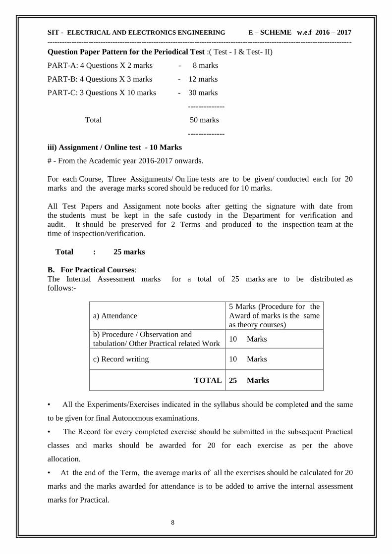
Question Paper Pattern for the Periodical Test :( Test - I & Test- II)
PART-A: 4 Questions X 2 marks - 8 marks
PART-B: 4 Questions X 3 marks - 12 marks
PART-C: 3 Questions X 10 marks - 30 marks
--------------
Total 50 marks
--------------
iii) Assignment / Online test - 10 Marks
# - From the Academic year 2016-2017 onwards.
For each Course, Three Assignments/ On line tests are to be given/ conducted each for 20
marks and the average marks scored should be reduced for 10 marks.
All Test Papers and Assignment note books after getting the signature with date from
the students must be kept in the safe custody in the Department for verification and
audit. It should be preserved for 2 Terms and produced to the inspection team at the
time of inspection/verification.
Total : 25 marks
B. For Practical Courses:
The Internal Assessment marks for a total of 25 marks are to be distributed as
follows:-
a) Attendance
5 Marks (Procedure for the
Award of marks is the same
as theory courses)
b) Procedure / Observation and
tabulation/ Other Practical related Work 10 Marks
c) Record writing 10 Marks
TOTAL 25 Marks
• All the Experiments/Exercises indicated in the syllabus should be completed and the same
to be given for final Autonomous examinations.
• The Record for every completed exercise should be submitted in the subsequent Practical
classes and marks should be awarded for 20 for each exercise as per the above
allocation.
• At the end of the Term, the average marks of all the exercises should be calculated for 20
marks and the marks awarded for attendance is to be added to arrive the internal assessment
marks for Practical.

SIT - ELECTRICAL AND ELECTRONICS ENGINEERING E – SCHEME w.e.f 2016 – 2017
------------------------------------------------------------------------------------------------------------------------------
9
• The students have to submit the duly signed bonafide record note book/file during
the Practical Autonomous Examinations.
• All the marks awarded for assignments, tests and attendance should be entered in
the Personal Log Book of the staff, who is handling the subject. This is applicable to
both Theory and Practical courses.
10. Life and Employability Skills Practical:
Life and Employability Skills Practical with more emphasis is being introduced in IV
Term for Circuit Branches and in V Term for other branches of Engineering.
Much Stress is given to increase the employability of the student
Internal Assessment Mark : 25 Marks
11. Project Work:
The students of all the Diploma Programmes have to do a Project Work as part of the
Curriculum and in partial fulfilment for the award of Diploma by the State Board of Technical
Education and Training, Tamilnadu. The Project work must be reviewed twice in the same
semester.
a) Internal assessment mark for Project Work:
Project Review I 10 marks
Project Review II 10 marks
Attendance 05 marks (Procedure for the Award of marks
is the same as theory courses)
Total 25 marks
Proper records are to be maintained for the two Project Reviews, and they should be preserved
for 2 Semesters and produced to the inspection team at the time of inspection/verification.
b) Allocation of Mark for Project Work & Viva Voce in Board Examination:
Viva Voce 30 marks
Marks for Report Preparation, Demonstration 35 marks
Written Test Mark $ (from 2 topics for 30
minutes duration) 10 Marks
Total 75 marks

SIT - ELECTRICAL AND ELECTRONICS ENGINEERING E – SCHEME w.e.f 2016 – 2017
------------------------------------------------------------------------------------------------------------------------------
10
Written Test Mark $:
i) Environment Management: 2 questions X 2 ½ marks = 5 marks
ii) Disaster Management: 2 questions X 2 ½ marks = 5 marks
Total = 10marks
Selection of Questions should be from Question Bank, by the External Examiner.
No choice to be given to the candidates.
12. Scheme of Examinations:
The Scheme of examinations for courses is given in Curriculam outline
13. Criteria for Pass:
1. No candidate shall be eligible for the award of Diploma unless he/she has undergone the
prescribed course of study successfully in an institution approved by AICTE and affiliated to
the State Board of Technical Education & Training, Tamil Nadu and pass all the
courses prescribed in the curriculum.
2. A candidate shall be declared to have passed the examination in a course if he/she
secures not less than 40% in theory courses and 50% in practical courses out of the total
prescribed maximum marks including both the Internal Assessment and the
Autonomous Examinations marks put together, subject to the condition that he/she secures
at least a minimum of 30 marks out of 75 marks in the Autonomous Theory Examinations and
a minimum of 35 marks out of 75 marks in the Autonomous Practical Examinations.
14. Classification of successful candidates:
Classification of candidates who will pass out the final examinations from April 2019 onwards
(Joined in first year in 2016-2017 / Joined in second year in 2017-2018) will be done as
specified below.
First Class with Superlative Distinction:
A candidate will be declared to have passed in First Class with Superlative Distinction if
he/she secures not less than 75% of the marks in all the courses and passes all the terms in the
first appearance itself and passes all courses within the stipulated period of study 3/ 3½ years
(Full Time/Sandwich) without any break in study.

SIT - ELECTRICAL AND ELECTRONICS ENGINEERING E – SCHEME w.e.f 2016 – 2017
------------------------------------------------------------------------------------------------------------------------------
11
First Class with Distinction:
A candidate will be declared to have passed in First Class with Distinction if he/she secures
not less than 75% of the aggregate of marks in all the terms put together and passes all the terms
except the I and II terms in the first appearance itself and passes all the courses within the
stipulated period of study 3/3½ years (Full Time/Sandwich) without any break in study.
First Class:
A candidate will be declared to have passed in First Class if he/she secures not less than 60%
of the aggregate marks in all terms put together and passes all the courses within the stipulated
period of study 3/3½ years (Full Time/Sandwich) without any break in study.
Second Class:
All other successful candidates will be declared to have passed in Second Class.
15. Duration of a period in the Class Time Table:
The duration of each period of instruction is 1 hour and the total period of instruction hours
excluding interval and Lunch break in a day should be uniformly maintained as 7 hours
corresponding to 7 periods of instruction (Theory & Practical).
******************************

SIT - ELECTRICAL AND ELECTRONICS ENGINEERING E – SCHEME w.e.f 2016 – 2017
------------------------------------------------------------------------------------------------------------------------------
12
3. SALIENT FEATURES
Name of the Programme : Diploma Programme in Electrical and Electronics
Engineering
Duration of the Programme : Three years (Six Semesters)
Entry Qualification : Matriculation or equivalent as prescribed by State
Board of Technical Education,Tamilnadu
Intake : : 60
Pattern Of the Programme : Term (Semester) Pattern
Ratio Between Theory &
Practical Classes
: 50 : 50
SIT - ELECTRICAL AND ELECTRONICS ENGINEERING E – SCHEME w.e.f 2016 – 2017
------------------------------------------------------------------------------------------------------------------------------
13
4. EMPLOYMENT OPPORTUNITIES FOR DIPLOMA HOLDERS IN
ELECTRICAL AND ELECTRONICS ENGINEERING
It is observed that employment in government/public sector undertakings are dwindling
day by day. Keeping present scenario in view, following employment opportunities are
visualized in different sectors of employment for diploma holders in electrical and
electronics engineering.
4.1 Manufacturing Industry (Mechanical)
The Electrical diploma holder will be involved in following activities in
mechanical manufacturing industry:
o Planning and execution for Electrical installation
o Distribution of Electrical Power
o Maintenance of Industrial Electrical System
o Repair and Maintenance of Electrical Machines and Equipment
o Repair and Maintenance of Electronic Control Circuitry
o Testing and Standardization for Quality Control
o Energy Conservation
4.2 Manufacturing Industry (Electrical and Electronics)
The Electrical diploma holder will be involved in following activities in Electrical
and Electronics manufacturing industry:
o Assistance in Research and Development
o Assistance in Planning, Designing and Detailing
o Shop-floor Management including Quality Control
o Power Generation and Distribution
o Installation of Electrical Power Supply Systems
o Maintenance of Electrical and Electronic System(s)
o Repair and Maintenance of Electrical Machines/Equipment (including testing)
o Production
o Inventory Management
o Marketing and Sales
4.3 Government Departments such as Electricity Board, MES, PWD, Railways, Air
bases, Airports, Defence, Thermal, Hydro and Nuclear Power Stations and other
Boards and Corporations
The Electrical diploma holder will be involved in following type of activities in
above mentioned Government Departments:
o Assistance in Planning and Design of Electrical generation, transmission,
distribution and protection system including testing, quality control

SIT - ELECTRICAL AND ELECTRONICS ENGINEERING E – SCHEME w.e.f 2016 – 2017
------------------------------------------------------------------------------------------------------------------------------
14
o Estimating for electrical installation Construction, erection and commissioning
of lines and Sub-stations
o Electrical Safety measures
o Operation and Maintenance of Lines and Sub-stations/underground cables
o Tariffs and Calculations of bills for consumption of electricity
o Inventory Management
o Repair and Maintenance of Electrical Machines/ Equipment
o Operation and maintenance of Thermal, Hydro and Nuclear Power Stations
4.4 Hospitals, Commercial Complexes, Service Sector Organizations like Hotels,
Tourist-Resorts, high-rise buildings, Cinema/Theater Halls etc.
Diploma holder in electrical engineering will be involved in following type of
activities in above mentioned Service Sector Organizations:
o Layout of wiring circuit, planning and execution for Electrical Installation
o Standby or captive Power Generation and its Distribution
o Maintenance of Electrical and Electronic Equipment
o Preventive Maintenance of Communication System, Lifts, Air-Conditioning
o Plants and Water Supply System
o Inventory Management
o Estimation for electrical repair and maintenance work
4.5 Self Employment
Following type of self employment opportunities are available to the diploma holder
in electrical engineering:
o Trading of Electrical Goods
o Establishing Repair and Maintenance Unit/ Centre
o Free Lancer for Repair and Maintenance of House-hold Electrical and
Electronic Gadgets such as: Washing Machines, Geysers, Air Conditioners,
Coolers and electrical installations etc.
o Electrical contractor
o Motor Winding Unit
o Auto-electrical Work
o Service sector
Can work as:
o Service and marketing engineer in the field of automation.
o Trainer of PLC & SCADA system.
o TSE ( Technical Support Executive)

SIT - ELECTRICAL AND ELECTRONICS ENGINEERING E – SCHEME w.e.f 2016 – 2017
------------------------------------------------------------------------------------------------------------------------------
15
4.6 JOB PROFILE/ ACTIVITY PROFILE
(01) Reading and interpreting drawings related to electrical machines, equipment,
wiring installations
(02) Selecting right kind and quality of materials
(03) Using measuring instruments, tools and testing devices for varied field
applications
(04) Understanding of constructional details, principle of working,
characteristics and application of electrical machines, equipment, appliances and
instruments
(05) Understanding of salient features and working principles of generation,
transmission, distribution, protection and utilization of electrical power in
different sectors
(06) Understanding of practices involved in erection, testing/installation and
commissioning of electrical machines, equipment, control panels and systems
(07) Troubleshooting of electrical machines, wiring installations, equipment and
control systems
(08) Knowledge and awareness of: Power Tariff (Power Trade and Control), Indian
Electricity rules, codes and Standards, Electrical Safety and Shock prevention
Measures ,Labour Management,
(09) Understanding of safety practices such as earthing, fire and shock prevention
measures adopted in industry and service sector
(10) Understanding the principles of basic and digital electronics, microprocessors
and micro-controller based systems and their applications in electrical control
circuits
(11) Uses Information Technology and computers for various applications in the
field of electrical engineering
(12) Knowledge and awareness of upcoming technologies of their field like
PLC,SCADA & DCS System
(13) Good knowledge of Electrical AutoCAD.
(14) Competencies in supervising shop floor/ work site operations
(15) Awareness about the environment, use of non-conventional energy sources,
external financial and technical support system, and energy conservation
techniques
(16) Knowledge of latest trends in the field of electronic controls, communication and
and instrumentation

SIT - ELECTRICAL AND ELECTRONICS ENGINEERING E – SCHEME w.e.f 2016 – 2017
------------------------------------------------------------------------------------------------------------------------------
16
5. COMPETENCY PROFILE OF DIPLOMA HOLDER IN ELECTRICAL
AND ELECTRONICS ENGINEERING
Keeping in view the employment scenario and requirement of four domains of learning viz.
Professional Development Domain, Continued Learning Domain, Human Relations
Domain and Personal Development Domain, a diploma holder in Electrical and
Electronics Engineering should have the:
1. Understanding of constructional details, principle of working, characteristics and
application of electrical machines, equipment, appliances and instruments
2. Understanding of salient features and working principles of generation, transmission,
distribution, protection and utilization of electrical power in different sectors
3. Ability to read and interpret drawings related to sub stations, electrical machines,
equipment, wiring installations for light and power.
4. Competency in selection of right kind and quality of materials and preparation of
estimates for installation of control panels used in industry
5. Ability to prepare tender document as per given drawings
6. Ability to use measuring instruments, tools and testing devices for varied field
applications
7. Competency in the design of control circuits for electrical machine control, control
panels, wiring circuits etc.
8. Ability to draw Ladder diagram and write Program for Control of Machines using PLC
9. Understanding of practices involved in erection, testing/installation and
commissioning of electrical machines, equipment, control panels and systems
10. Ability for fault diagnosis and repair of electrical machines, wiring installations,
equipment and control systems
11. Knowledge and awareness of:
o Power Tariff (Power Trade and Control)
o Indian Electricity rules, codes and Standards
o Safety and Shock prevention Measures
o Labour Management
o Technical Report-writing Skills
o Team Working, Interpersonal Relations and Human Values
o Entrepreneurship Development (Self Employment )
o Concern for wastage
11. Understanding of safety practices such as earthing, fire and shock prevention measures
adopted in industry and service sector
12. Understanding the principles of basic and digital electronics, microprocessors and
micro- controller based systems and their applications in electrical control circuits.
13. Ability to use Information Technology and computers for various applications in the
field of electrical engineering.
14. Knowledge of applied and engineering sciences for better comprehension of
technologies used in electrical industry and service sector and to develop scientific
temper, analytical skills and to facilitate continuing education.

SIT - ELECTRICAL AND ELECTRONICS ENGINEERING E – SCHEME w.e.f 2016 – 2017
------------------------------------------------------------------------------------------------------------------------------
17
15. Competencies in general, manual and machining skills for supervising shop floor/ work
site operations
16. Proficiency in oral and written communication, technical report writing, managing
relationship with juniors, pears and seniors for effective functioning in the world of
work
17. Competency in solving simple problems related to various functional areas of
electrical and electronics engineering may it be prototype development, diagnostic and
fault finding or repair and maintenance of plant and equipment
18. Understanding of basic principles of managing men, material and equipment and
techniques of achieving economy and quality
19. Awareness about the environment, use of non-conventional energy sources, external
financial and technical support system, adopting energy conservation techniques
20. Knowledge of latest trends in the field of electronic controls, communication and
instrumentation.
SIT - ELECTRICAL AND ELECTRONICS ENGINEERING E – SCHEME w.e.f 2016 – 2017
------------------------------------------------------------------------------------------------------------------------------
18
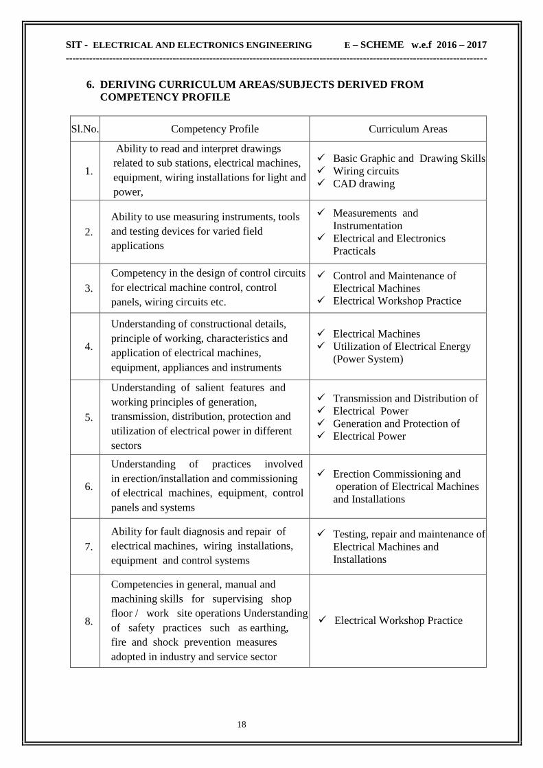
6. DERIVING CURRICULUM AREAS/SUBJECTS DERIVED FROM
COMPETENCY PROFILE
Sl.No. Competency Profile Curriculum Areas
1.
Ability to read and interpret drawings
related to sub stations, electrical machines,
equipment, wiring installations for light and
power,
Basic Graphic and Drawing Skills
Wiring circuits
CAD drawing
2.
Ability to use measuring instruments, tools
and testing devices for varied field
applications
Measurements and
Instrumentation
Electrical and Electronics
Practicals
3.
Competency in the design of control circuits
for electrical machine control, control
panels, wiring circuits etc.
Control and Maintenance of
Electrical Machines
Electrical Workshop Practice
4.
Understanding of constructional details,
principle of working, characteristics and
application of electrical machines,
equipment, appliances and instruments
Electrical Machines
Utilization of Electrical Energy
(Power System)
5.
Understanding of salient features and
working principles of generation,
transmission, distribution, protection and
utilization of electrical power in different
sectors
Transmission and Distribution of
Electrical Power
Generation and Protection of
Electrical Power
6.
Understanding of practices involved
in erection/installation and commissioning
of electrical machines, equipment, control
panels and systems
Erection Commissioning and
operation of Electrical Machines
and Installations
7.
Ability for fault diagnosis and repair of
electrical machines, wiring installations,
equipment and control systems
Testing, repair and maintenance of
Electrical Machines and
Installations
8.
Competencies in general, manual and
machining skills for supervising shop
floor / work site operations Understanding
of safety practices such as earthing,
fire and shock prevention measures
adopted in industry and service sector
Electrical Workshop Practice

SIT - ELECTRICAL AND ELECTRONICS ENGINEERING E – SCHEME w.e.f 2016 – 2017
------------------------------------------------------------------------------------------------------------------------------
19
Sl.No. Competency Profile Curriculum Areas
9.
Competency in selection of right kind and
quality of materials and preparation of
estimates for installation of control panels used
in industry
Electrical Engineering
Drawing
Estimation and Costing
10. Ability to prepare tender document as per given
drawings
Electrical Estimation and
Costing
11.
Understanding the principles of basic and digital
electronics, microprocessors and micro-
controller based systems and their applications
in electrical control circuits
Digital Electronics
Programmable Logic
Controllers (PLCs)
Microcontrollers
12.
Ability to use Information Technology
and computers for various applications in the
field of electrical engineering and Programming
skill
C++ Programming
CAD & Simulation
Computer Networks
13.
Knowledge of applied and engineering sciences
for better comprehension of technologies used
in electrical industry and service sector and to
develop scientific temper, analytical skills and
to facilitate continuing education
Engineering Physics
Engineering Chemistry
Applied Mathematics
Workshop Practice
14.
Proficiency in oral and written
communication, technical report writing,
managing relationship with juniors, pears and
seniors for effective functioning in the world of
work
Communication Skills
Project Work
Exposure to World of Work
Industrial Training
15
Competency in solving simple problems related
to various functional areas of electrical
engineering may it be prototype development,
diagnostic and fault finding or repair and
maintenance of plant and equipment
Control and Maintenance of
Electrical equipments
Estimation and
.16
Awareness about the environment, use of non-
conventional energy sources, external financial
and technical support system, adopting energy
conservation techniques
Environmental Education
Renewable (Non-
Conventional) Sources of
Energy

SIT - ELECTRICAL AND ELECTRONICS ENGINEERING E – SCHEME w.e.f 2016 – 2017
------------------------------------------------------------------------------------------------------------------------------
20
6.1 ABSTRACT OF CURRICULUM AREAS / SUBJECTS
a) Basic Sciences and Humanities Communication Skills – I & II
Life & Employability Skills
b) Applied Sciences
Engineering Mathematics – I & II
Applied Mathematics
Engineering Physics I & II
Engineering Chemistry I & II
c) Basic Courses in
Engineering Engineering Drawing I&II
Workshop Practice
d) Core Courses in Electrical &
Electronics Engineering
Electrical Circuit Theory
Electrical Machines – I
Electronic Devices and Circuits
Measurements and Instrumentation.
e) Applied Courses in Electrical &
Electronics Engineering
Electrical Machines – II
Analog and Digital Electronics
Electrical Workshop Practice
Power System – I
Power System – II
Control and Maintenance of Electrical
Machines
Electrical Machine Design
Power Electronics
Renewable Energy Sources & Energy
Auditing
Wiring, Winding and Estimation
e) Specialized (Diversified) Courses in
Electrical & Electronics Engineering C++ Programming
Micro Controller
VLSI Design
CAD & Simulation
Programmable Logic Controller
Bio-Medical Instrumentation
Computer Hardware and Networking
Project work

SIT - ELECTRICAL AND ELECTRONICS ENGINEERING E – SCHEME w.e.f 2016 – 2017
------------------------------------------------------------------------------------------------------------------------------
21
7. CURRICULUM OUTLINE
TERM - III
Sl
No
Course
Code Course Title
Teaching Scheme Scheme Of Examination
L T P C Inter
nal
End
Exam Total
Min.
Mark
For
Pass
Dura
tion
1 2E3201 Electrical Circuit Theory 5 --- --- 5 25 75 100 40 3
2 2E3202 Electrical Machines – I 5 --- --- 5 25 75 100 40 3
3 2E3203 Electronic Devices &
Circuits 5 --- --- 5 25 75 100 40 3
4 2E3401 C++ Programming 4 --- --- 4 25 75 100 40 3
5 2E3204 Electrical Machines-I Lab --- --- 6 3 25 75 100 50 3
6 2E3205 Electronic Devices &
Circuits Lab --- --- 4 2 25 75 100 50 3
7 2E3402 C++ Programming Lab --- 2 4 4 25 75 100 50 3
TOTAL 19 2 14 28 175 525 700

SIT - ELECTRICAL AND ELECTRONICS ENGINEERING E – SCHEME w.e.f 2016 – 2017
------------------------------------------------------------------------------------------------------------------------------
22
TERM - IV
Sl
No
Course
Code Course Title
Teaching Scheme Scheme Of Examination
L T P C Inter
nal
End
Exam Total
Min.
Mark
For
Pass
Dura
tion
1 2E4301 Electrical Machines – II 5 --- --- 5 25 75 100 40 3
2 2E4302 Analog & Digital
Electronics 5 --- --- 5 25 75 100 40 3
3 2E4206 Measurements &
Instrumentation 5 --- --- 5 25 75 100 40 3
4 2E4303 Electrical Machines-II
Lab --- --- 6 3 25 75 100 50 3
5 2E4304 Analog & Digital
Electronics Lab --- --- 4 2 25 75 100 50 3
6 2E4305 Electrical Workshop 2 --- 4 4 25 75 100 50 3
7 2E4207 Life &Employability skill
Practical 2 --- 2 3 25 75 100 50 3
TOTAL 19 0 16 27 175 525 700

SIT - ELECTRICAL AND ELECTRONICS ENGINEERING E – SCHEME w.e.f 2016 – 2017
------------------------------------------------------------------------------------------------------------------------------
23
TERM -V
Sl
No
Course
Code Course Title
Teaching Scheme Scheme Of Examination
L T P C Inter
nal
End
Exam Total
Min.
Mark
For
Pass
Dura
tion
1 2E5306 Power System – I 5 --- --- 5 25 75 100 40 3
2 2E5307 Control & Maintenance
of Electrical Machines 5 --- --- 5 25 75 100 40 3
3
Elective Theory - I ( Any One)
5 --- --- 5 25 75 100 40 3
2E5403.1 Micro Controller
2E5403.2 VLSI Design
2E5403.3 Electrical Machine
Design
4 2E5308
Control & Maintenance
of Electrical Machines
Lab
--- --- 6 3 25 75 100 50 3
5 2E5309 Wiring, Winding &
Estimation Lab 2 --- 4 4 25 75 100 50 3
6
Elective Practical – I (Any One)
--- --- 4 2 25 75 100 50 3
2E5404.1 Micro Controller Lab
2E5404.2 VLSI Design Lab
2E5404.3 Electrical Machine
Design Lab
7 2E5405 CAD & Simulation Lab 2 --- 2 3 25 75 100 50 3
TOTAL 19 0 16 27 175 525 700

SIT - ELECTRICAL AND ELECTRONICS ENGINEERING E – SCHEME w.e.f 2016 – 2017
------------------------------------------------------------------------------------------------------------------------------
24
TERM - VI
Sl
No
Course
Code Course Title
Teaching Scheme Scheme Of Examination
L T P C Inter
nal
End
Exam Total
Min.
Mark
For
Pass
Dura
tion
1 2E6310 Power System - II 5 --- --- 5 25 75 100 40 3
2 2E6311 Power Electronics 5 --- --- 5 25 75 100 40 3
3 2E6312
Renewable Energy
Sources & Energy
Auditing
5 --- --- 5 25 75 100 40 3
4
Elective Theory - II ( Any One)
4 --- --- 4 25 75 100 40 3
2E6406.1 Programmable Logic
Controller
2E6406.2 Bio-Medical
Instrumentation
2E6406.3 Computer Hardware &
Networking
5 2E6313 Power Electronics Lab --- --- 6 3 25 75 100 50 3
6
Elective Practical – II (Any One)
--- --- 4 2 25 75 100 50 3
2E6407.1 Programmable Logic
Controller Lab
2E6407.2 Bio-Medical
Instrumentation Lab
2E6407.3 Computer Hardware &
Networking Lab
7 2E6408 Project Work 2 --- 4 4 25 75 100 50 3
TOTAL 21 0 14 28 175 525 700

SIT - ELECTRICAL AND ELECTRONICS ENGINEERING E – SCHEME w.e.f 2016 – 2017
------------------------------------------------------------------------------------------------------------------------------
25
8. HORIZONTAL AND VERTICAL ORGANISATION OF THE COURSES
Sl.No. Subject Distribution of credits
Basic Core Applied Diversified
1. Communication English – I 4 - - -
2. Engineering Mathematics – I 7 - - -
3. Engineering Physics – I 5 - - -
4. Engineering Chemistry – I 5 - - -
5. Engineering Physics Practical – I 1 - - -
6. Engineering Chemistry Practical – I 1 - - -
7. Engineering Graphics - I 4 - - -
8 Workshop Practice 2 - - -
9 Communication English – II 5 - -
10 Engineering Mathematics – II 5 - -
11 Applied Mathematics 5 - -
12 Engineering Physics – II 5 - -
13 Engineering Chemistry – II 5 - -
14 Engineering Physics Practical – II 1 - -
15 Engineering Chemistry Practical – II 1 - -
16 Engineering Graphics - II 4 - -
17. Electrical Circuit Theory - 5 - -
18 Electrical Machines-I - 5 - -
19 Electronic Devices & Circuits - 5 - -
20 C++ Pr ogramming - - - 4
21 Electrical Machines-I Lab - 3 - -
22 Electronic Devices & Circuits Lab - 2 - -
23 C++ Programming Lab - - - 4
24 Electrical Machines – II - - 5 -
25 Analog & Digital Electronics - - 5 -
26 Measurements & Instrumentation - 5 - -
27 Electrical Machines-II Lab - - 3 -

SIT - ELECTRICAL AND ELECTRONICS ENGINEERING E – SCHEME w.e.f 2016 – 2017
------------------------------------------------------------------------------------------------------------------------------
26
Sl.No. Subject Distribution of credits
Basic Core Applied Diversified
28 Analog & Digital Electronics Lab - - 2 -
29 Electrical Workshop - - 4 -
30 Life &Employability skill Practical - 3 - -
31 Power System – I - - 5 -
32 Control & Maintenance of Electrical
Machines - - 5 -
33 Elective – I Theory - - - 5
34 Control & Maintenance of Electrical
Machines Lab - - 3 -
35 Wiring, Winding & Estimation Lab - - 4 -
36 Elective – I Practical - - - 2
37 CAD & Simulation Lab - - - 3
38 Power System - II - - 5 -
39 Power Electronics - - 5 -
40 Renewable Energy Sources &
Energy Auditing - - 5 -
41 Elective – II Theory - - - 4
42 Power Electronics Lab - - 3 -
43 Elective –II Practical - - - 2
44 Project work - - - 4
Total 60 28 54 28
SIT - ELECTRICAL AND ELECTRONICS ENGINEERING E – SCHEME w.e.f 2016 – 2017
------------------------------------------------------------------------------------------------------------------------------
27
Detailed Content
of
Various Courses

SIT - ELECTRICAL AND ELECTRONICS ENGINEERING E – SCHEME w.e.f 2016 – 2017
------------------------------------------------------------------------------------------------------------------------------
28
TERM - III

SIT - ELECTRICAL AND ELECTRONICS ENGINEERING E – SCHEME w.e.f 2016 – 2017
------------------------------------------------------------------------------------------------------------------------------
29
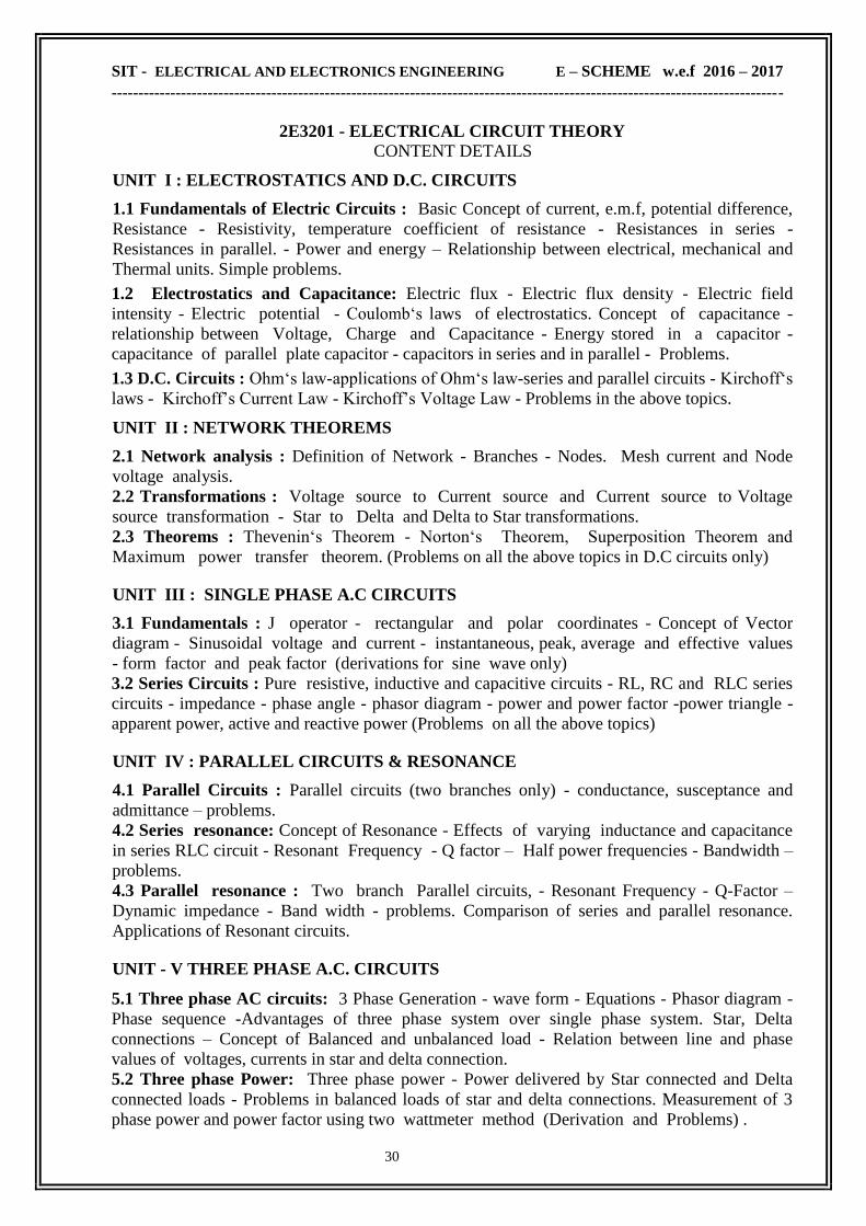
2E3201 - ELECTRICAL CIRCUIT THEORY
RATIONALE
Study of Electric Circuits is an essential in study of Electrical and Electronics
Engineering. The subject forms the foundation of Electrical and Electronics Engineering. It
prepares the students to familiarize with basic concepts and principles of electrical circuits.
Study of Circuits and Network constitutes the basic and fundamental aspect of deriving insight
into the functioning and analysis of Electrical network, instruments and machineries.
OBJECTIVES Understand the fundamentals of Electrostatics
Apply Kirchhoff's current and voltage laws and Ohm's law to circuit problems
Simplify circuits using series and parallel equivalents
Perform Network analysis and other solving techniques for DC circuits
Solve circuit problems using Theorems
Perform Network analysis and other solving techniques for DC circuits.
Understand the basic knowledge on single phase and three phase A.C circuits
Develop knowledge on RLC series and parallel resonance.
SCHEME OF INSTRUCTION & EXAMINATION
Course
Code
Instruction
Credit
Scheme Of Examination
Hours /
week
Hours /
Term
Marks Duration
Internal End Exam Total
2E3201 5 75 5 25 75 100 3
TOPICS AND ALLOCATION OF HOURS & MARKS
Unit No Name of the Topic Hours Marks
I Electrostatics and D.C. Circuits 12 15
II Network Theorems 13 15
III Single phase A.C Circuits 13 15
IV Parallel Circuits & Resonance 12 15
V Three phase A.C. Circuits 13 15
Revision 05
Cycle Tests and Model Examination 07
Total 75 75
SIT - ELECTRICAL AND ELECTRONICS ENGINEERING E – SCHEME w.e.f 2016 – 2017
------------------------------------------------------------------------------------------------------------------------------
30
2E3201 - ELECTRICAL CIRCUIT THEORY
CONTENT DETAILS
UNIT I : ELECTROSTATICS AND D.C. CIRCUITS
1.1 Fundamentals of Electric Circuits : Basic Concept of current, e.m.f, potential difference,
Resistance - Resistivity, temperature coefficient of resistance - Resistances in series -
Resistances in parallel. - Power and energy – Relationship between electrical, mechanical and
Thermal units. Simple problems.
1.2 Electrostatics and Capacitance: Electric flux - Electric flux density - Electric field
intensity - Electric potential - Coulomb‗s laws of electrostatics. Concept of capacitance -
relationship between Voltage, Charge and Capacitance - Energy stored in a capacitor -
capacitance of parallel plate capacitor - capacitors in series and in parallel - Problems.
1.3 D.C. Circuits : Ohm‗s law-applications of Ohm‗s law-series and parallel circuits - Kirchoff‗s
laws - Kirchoff‘s Current Law - Kirchoff‘s Voltage Law - Problems in the above topics.
UNIT II : NETWORK THEOREMS
2.1 Network analysis : Definition of Network - Branches - Nodes. Mesh current and Node
voltage analysis.
2.2 Transformations : Voltage source to Current source and Current source to Voltage
source transformation - Star to Delta and Delta to Star transformations.
2.3 Theorems : Thevenin‗s Theorem - Norton‗s Theorem, Superposition Theorem and
Maximum power transfer theorem. (Problems on all the above topics in D.C circuits only)
UNIT III : SINGLE PHASE A.C CIRCUITS
3.1 Fundamentals : J operator - rectangular and polar coordinates - Concept of Vector
diagram - Sinusoidal voltage and current - instantaneous, peak, average and effective values
- form factor and peak factor (derivations for sine wave only)
3.2 Series Circuits : Pure resistive, inductive and capacitive circuits - RL, RC and RLC series
circuits - impedance - phase angle - phasor diagram - power and power factor -power triangle -
apparent power, active and reactive power (Problems on all the above topics)
UNIT IV : PARALLEL CIRCUITS & RESONANCE
4.1 Parallel Circuits : Parallel circuits (two branches only) - conductance, susceptance and
admittance – problems.
4.2 Series resonance: Concept of Resonance - Effects of varying inductance and capacitance
in series RLC circuit - Resonant Frequency - Q factor – Half power frequencies - Bandwidth –
problems.
4.3 Parallel resonance : Two branch Parallel circuits, - Resonant Frequency - Q-Factor –
Dynamic impedance - Band width - problems. Comparison of series and parallel resonance.
Applications of Resonant circuits.
UNIT - V THREE PHASE A.C. CIRCUITS
5.1 Three phase AC circuits: 3 Phase Generation - wave form - Equations - Phasor diagram -
Phase sequence -Advantages of three phase system over single phase system. Star, Delta
connections – Concept of Balanced and unbalanced load - Relation between line and phase
values of voltages, currents in star and delta connection.
5.2 Three phase Power: Three phase power - Power delivered by Star connected and Delta
connected loads - Problems in balanced loads of star and delta connections. Measurement of 3
phase power and power factor using two wattmeter method (Derivation and Problems) .

SIT - ELECTRICAL AND ELECTRONICS ENGINEERING E – SCHEME w.e.f 2016 – 2017
------------------------------------------------------------------------------------------------------------------------------
31
TEXT BOOK
Sl.No. Title Author Publisher
1 Electric circuit theory
5th Edition-2008
Dr.M.Arumugam
Dr.N. Premkumaran
Khanna Publishers, New
Delhi.,
REFERENCE BOOKS
Sl.No. Title Author Publisher
1
A Text book of Electrical
Technology volume-I
MCE-23-2015
B.L.Theraja S.Chand & Co New Delhi
2
Fundamentals OF
Electrical circuit theory
7th Edition-2006
B. Chattopadhyay
P.C.Rakshit S.Chand & Co New Delhi
3 Circuit and networks
4th Edition-2010
A. Sudhakar &
Shyam Mohan S Palli Tata -Mc Graw Hill.
ONLINE RESOURCES
www.allaboutcircuits.com/textbook/direct.../electric-circuits/
www.electrical4u.com/electrical-engineering-objective-questions-mcq/
COURSE OUTCOME
CO1 Able to understand the fundamentals of Electrostatics and DC circuits
CO2 Able to solve circuits using network theorems
CO3 Able to understand the concept of single phase AC supply
CO4 Knowledge in series and parallel resonance
CO5 Able to understand the concept of three phase AC supply

SIT - ELECTRICAL AND ELECTRONICS ENGINEERING E – SCHEME w.e.f 2016 – 2017
------------------------------------------------------------------------------------------------------------------------------
32
2E3202 - ELECTRICAL MACHINES – I
RATIONALE
This subject is classified under core technology group which intends to teach facts,
concepts, principles & procedure for operation & testing of electrical machines, such as DC
generators, DC motors and single & three phase transformers. Student will be able to analyze the
characteristics of DC motors, Transformers & Qualitative Parameters of these machines.
Knowledge gained by the students will be helpful in the study of technological subjects such as
Power systems, utilization of electrical energy, manufacturing processes & testing and
maintenance of electrical machines.
OBJECTIVES
Understand the concept of magnetic circuit principle and associated laws
Know the DC generator principle, construction, types, characteristics, efficiency and
applications.
Know the DC motor principle, construction, types, characteristics, testing and starters.
Know the principle, construction & characteristics of single phase transformer, auto
transformer
Know the principle, construction and characteristics of three phase transformer
Know the different connection and paralleling of transformers
Know the Maintenance of DC machines
Get an overview of Batteries
SCHEME OF INSTRUCTION & EXAMINATION
Course
Code
Instruction
Credit
Scheme Of Examination
Hours /
week
Hours /
Term
Marks Duration
Internal End Exam Total
2E3202 5 75 5 25 75 100 3
TOPICS AND ALLOCATION OF HOURS & MARKS :
Unit No Name of the Topic Hours Marks
I D.C Generators 12 15
II D.C Motors 13 15
III Single phase Transformers 13 15
IV Three phase Transformers 13 15
V Storage Batteries 12 15
Revision 05
Cycle Tests and Model Examination 07
Total 75 75

SIT - ELECTRICAL AND ELECTRONICS ENGINEERING E – SCHEME w.e.f 2016 – 2017
------------------------------------------------------------------------------------------------------------------------------
33
2E3202 - ELECTRICAL MACHINES - I
CONTENT DETAILS
UNIT I : D C GENERATORS
1.1 Principle : Review of electromagnetic induction – Properties of Magnetic flux - Faraday‘s
laws – Fleming‘s right hand rule – Principle of operation of D.C. generators –Construction of
D.C. generators – Field system– Types of armature windings – Principles of lap and wave
windings – EMF equation – simple problems. .
1.2 Characteristics of D.C. generators – Building up of voltage of D.C. Shunt generators ––
No load characteristics of Shunt generator –Determination of critical field resistance – Causes of
failure to build-up voltage and remedy – Load characteristics of series and shunt generators –
load characteristics of cumulatively and differentially compounded generators .
1.3 Applications of DC Generators - armature reaction – methods of compensating armature
reaction – process of commutation
UNIT II : D C MOTORS
2.1 Principle of D.C. Motors – Fleming‘s left hand rule – Construction and working of DC
motor – Back emf – Torque equation.
2.2 Characteristics of DC motors: Torque-current, Speed-current, Speed-Torque characteristics
of different motors – Speed control of DC motors – Field control and armature control –
necessity of Starters – 3 point and 4 point starter - losses in D.C. Machines.
2.3 Testing of D.C. machines – Predetermination of efficiency of motor and generator by
Swinburne‘s test – Problems in above topics – Applications of D.C. Motors.
UNIT III : SINGLE PHASE TRANSFORMERS
3.1Principle & Construction – Working principle of Transformer - constructional details of
core, shell type transformers – coil assembly.
3.2 EMF Equation – Voltage ratio – Transformer on No load – Transformer on load – Current
ratio – Phasor diagram on no load and on load at different power factors – O.C. test, S.C. test –
Determination of equivalent circuit constants– Determination of voltage regulation and
efficiency – Condition for maximum efficiency– Problems on the above topics
3.3 All day efficiency - polarity test– Parallel operation of single phase transformers– Auto
transformer – principle – saving of copper – applications.
UNIT IV : THREE PHASE TRANSFORMERS
4.1 Three phase Transformer construction – Construction of Three phase Transformer -
Types of connections – Star-star, Star-Delta, Delta-Star, Delta-delta connections – Scott
connection - V connection of transformer – Parallel operation of three phase transformers.
4.2 Grouping of transformers - Conditions – Phasing out test – Pairing of transformer - Load
sharing of transformers with equal and unequal ratings
4.3 Accessories & Testing of transformers – Various cooling arrangements – Transformer
accessories – conservator – breather – explosion vent – Bucholz relay–ON load and OFF load
tap changer – Transformer oil tester – Acidity test -– Earthing – Measurement of earth resistance.
UNIT V : STORAGE BATTERIES
Classification of cells – construction – chemical action and physical changes during charging
and discharging - internal resistance and specific gravity of lead acid, nickel iron and nickel
cadmium cells – indication of fully charged and discharged battery. Defects and their remedies –
capacity – methods of charging – maintenance – applications.

SIT - ELECTRICAL AND ELECTRONICS ENGINEERING E – SCHEME w.e.f 2016 – 2017
------------------------------------------------------------------------------------------------------------------------------
34
TEXT BOOK
Sl.No. Title Author Publisher
1
A course in Electrical
Technology (Vol - II)
MCE-2005
B.L.Theraja S.Chand & Co New Delhi
REFERENCE BOOKS
Sl.No. Title Author Publisher
1
Electrical machines A
course of Electrical Engg
4th Edition-2014.
K.Bhattacharya,
Principal,TTTI,
Chandigar
Tata -Mc Graw Hill ,
New Delhi
2 Operation & Maintenance
of Electrical Machines B.V.S. Rao
Khanna Publishers, New
Delhi
3 Electrical Technology
10th Edition -2010
Edward
Hughes
Addision – Wesley
International Student Ed.
ONLINE RESOURCES
www.nptel.ac.in/courses/108105017/
www.nptel.ac.in/courses/108106071/
www.electrical4u.com/battery-history-and-working-principle-of-batteries/
COURSE OUTCOME
CO1
Able to Understand the concept of magnetic circuits.
Able to Know the DC generator principle, construction, types, characteristics,
efficiency and applications.
CO2 Able to Know the DC motor principle, construction, types, characteristics, efficiency
and applications.
CO3 Able to Know the single phase Transformer principle, construction, types,
characteristics, efficiency and applications.
CO4 Able to Know the three phase Transformer principle, construction, types,
characteristics, efficiency and applications.
CO5 Able to understand the concept of Batteries.

SIT - ELECTRICAL AND ELECTRONICS ENGINEERING E – SCHEME w.e.f 2016 – 2017
------------------------------------------------------------------------------------------------------------------------------
35
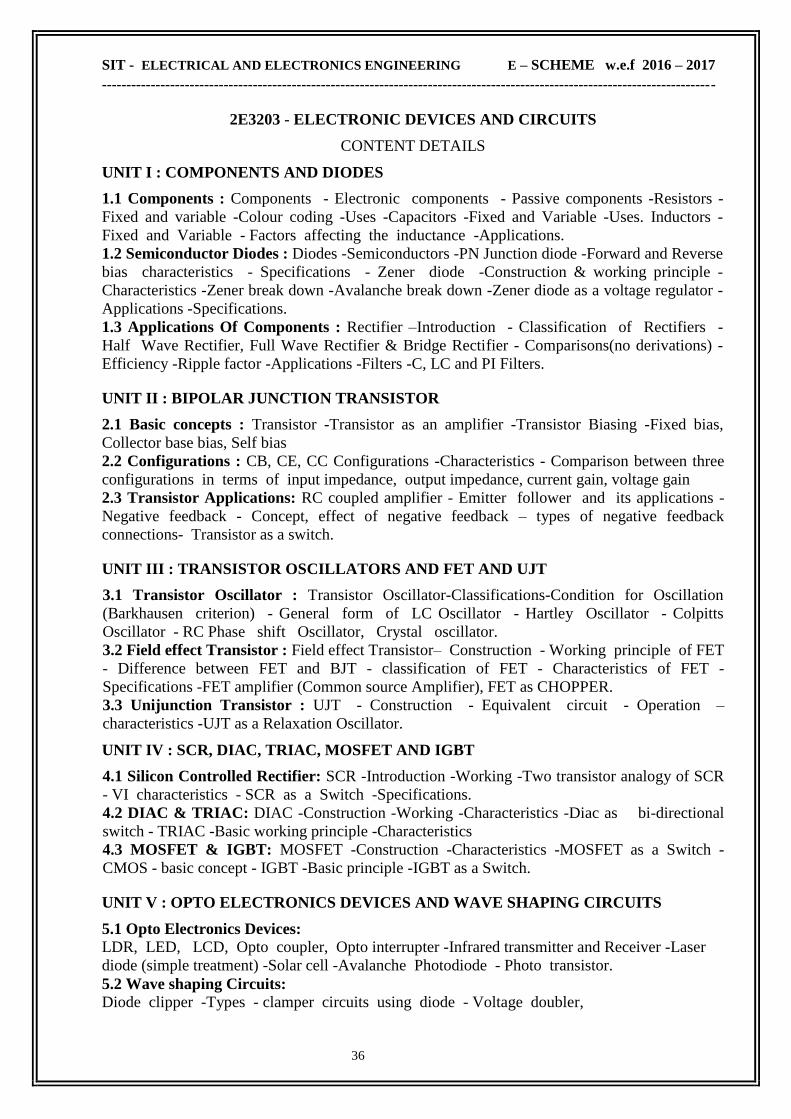
2E3203 - ELECTRONIC DEVICES AND CIRCUITS
RATIONALE The aim of introducing this course is to impart knowledge of basic Electronics devices to
the students of Electronics Engineering. Through the study of this course, the students will get
knowledge of construction, working & characteristics of various types of diodes and transistors.
The study of the devices will be helpful to understand the various basic and applied technology
courses.
OBJECTIVES
Familiarize various passive and active components
Study the working principle of PN junction diode and transistor
Understand the working principle of different types of rectifiers
Differentiate various types of amplifiers
Study the performance of special devices like UJT, FET
Study the performance of different transistor oscillators
Study the performance of SCR, DIAC, TRIAC and IGBT
Know the construction and working principle of optoelectronic devices
Study the performance of solar cell
Explain the concept of wave shaping circuits such as clippers and clampers
SCHEME OF INSTRUCTION & EXAMINATION
Course
Code
Instruction
Credit
Scheme Of Examination
Hours /
week
Hours /
Term
Marks Duration
Internal End Exam Total
2E3203 5 75 5 25 75 100 3
TOPICS AND ALLOCATION OF HOURS & MARKS :
Unit No Name of the Topic Hours Marks
I Components and Diodes 12 15
II Bipolar Junction Transistor 13 15
III Transistor oscillators and FET and UJT 13 15
IV SCR, DIAC, TRIAC, MOSFET and IGBT 13 15
V Opto Electronics Devices and Wave shaping Circuits 12 15
Revision 05
Cycle Tests and Model Examination 07
Total 75 75
SIT - ELECTRICAL AND ELECTRONICS ENGINEERING E – SCHEME w.e.f 2016 – 2017
------------------------------------------------------------------------------------------------------------------------------
36
2E3203 - ELECTRONIC DEVICES AND CIRCUITS
CONTENT DETAILS
UNIT I : COMPONENTS AND DIODES
1.1 Components : Components - Electronic components - Passive components -Resistors -
Fixed and variable -Colour coding -Uses -Capacitors -Fixed and Variable -Uses. Inductors -
Fixed and Variable - Factors affecting the inductance -Applications.
1.2 Semiconductor Diodes : Diodes -Semiconductors -PN Junction diode -Forward and Reverse
bias characteristics - Specifications - Zener diode -Construction & working principle -
Characteristics -Zener break down -Avalanche break down -Zener diode as a voltage regulator -
Applications -Specifications.
1.3 Applications Of Components : Rectifier –Introduction - Classification of Rectifiers -
Half Wave Rectifier, Full Wave Rectifier & Bridge Rectifier - Comparisons(no derivations) -
Efficiency -Ripple factor -Applications -Filters -C, LC and PI Filters.
UNIT II : BIPOLAR JUNCTION TRANSISTOR
2.1 Basic concepts : Transistor -Transistor as an amplifier -Transistor Biasing -Fixed bias,
Collector base bias, Self bias
2.2 Configurations : CB, CE, CC Configurations -Characteristics - Comparison between three
configurations in terms of input impedance, output impedance, current gain, voltage gain
2.3 Transistor Applications: RC coupled amplifier - Emitter follower and its applications -
Negative feedback - Concept, effect of negative feedback – types of negative feedback
connections- Transistor as a switch.
UNIT III : TRANSISTOR OSCILLATORS AND FET AND UJT
3.1 Transistor Oscillator : Transistor Oscillator-Classifications-Condition for Oscillation
(Barkhausen criterion) - General form of LC Oscillator - Hartley Oscillator - Colpitts
Oscillator - RC Phase shift Oscillator, Crystal oscillator.
3.2 Field effect Transistor : Field effect Transistor– Construction - Working principle of FET
- Difference between FET and BJT - classification of FET - Characteristics of FET -
Specifications -FET amplifier (Common source Amplifier), FET as CHOPPER.
3.3 Unijunction Transistor : UJT - Construction - Equivalent circuit - Operation –
characteristics -UJT as a Relaxation Oscillator.
UNIT IV : SCR, DIAC, TRIAC, MOSFET AND IGBT
4.1 Silicon Controlled Rectifier: SCR -Introduction -Working -Two transistor analogy of SCR
- VI characteristics - SCR as a Switch -Specifications.
4.2 DIAC & TRIAC: DIAC -Construction -Working -Characteristics -Diac as bi-directional
switch - TRIAC -Basic working principle -Characteristics
4.3 MOSFET & IGBT: MOSFET -Construction -Characteristics -MOSFET as a Switch -
CMOS - basic concept - IGBT -Basic principle -IGBT as a Switch.
UNIT V : OPTO ELECTRONICS DEVICES AND WAVE SHAPING CIRCUITS
5.1 Opto Electronics Devices:
LDR, LED, LCD, Opto coupler, Opto interrupter -Infrared transmitter and Receiver -Laser
diode (simple treatment) -Solar cell -Avalanche Photodiode - Photo transistor.
5.2 Wave shaping Circuits: Diode clipper -Types - clamper circuits using diode - Voltage doubler,

SIT - ELECTRICAL AND ELECTRONICS ENGINEERING E – SCHEME w.e.f 2016 – 2017
------------------------------------------------------------------------------------------------------------------------------
37
TEXT BOOK
Sl.No. Title Author Publisher
1 Principles of electronics
Re-Ed, 2010 V.K. Mehta S.Chand & Co
REFERENCE BOOKS
Sl.No. Title Author Publisher
1
Electronic devices applications
and integrated circuits
5th Edition, 2010
Mathur
Kulshreshtha Chadha
Umesh publications,
New Delhi – 6
2 Integrated circuits
1st Edition, 2008 K.R. Botkar
Khanna Publishers, New
Delhi
3 Electronic devices and circuits
23rd Edition, 2008 G.K. Mithal
Khanna Publishers, New
Delhi
4 Electronic devices and circuits
2nd Edition 2008
Salivahanan,
N.Suresh Kumar
A.Vallavaraj
Tata -Mc Graw Hill ,
New Delhi
ONLINE RESOURCES
www.electronics.wisc-online.com/category.aspx
www.electrical4u.com/theory-of-semiconductor/
COURSE OUTCOME
CO1 Able to identify electronic components and Understand the working principle of
different types of rectifiers
CO2 Able to know different configurations of transistor and their applications.
CO3 Able to understand different devices like FET, UJT and their applications.
CO4 Able to understand power electronic devices like SCR, DIAC, TRIAC, MOSFET
AND IGBT and their applications.
CO5 Knowing the concept of wave shaping circuits such as clippers and clampers

SIT - ELECTRICAL AND ELECTRONICS ENGINEERING E – SCHEME w.e.f 2016 – 2017
------------------------------------------------------------------------------------------------------------------------------
38
2E3401 C++ PROGRAMMING
RATIONALE
Computers are now-a-days necessary in human routine life. At each and every stage, we find its
importance. In technical side, engineers are using computers extensively to solve their design
problems. Here, an attempt is made to generate different skills in C++ programming like the
concept of function over loading, classes and objects, constructers, operator over loading, virtual
function and writing and reading the data from a file.
OBJECTIVES
After the completion of this laboratory, the student should be able to
Understand the concepts of OOPs, their advantages and applications
Comprehend the features of C++
Know to create classes, objects, constructors and destructors
Know the concepts and advantages of overloading operator and type conversions
Appreciate the concepts of inheritance and the various types of inheritance.
Understand virtual functions & their need and usage
Appreciate the need for manipulators and the design of the same
Use the various operations of files to perform file operations.
SCHEME OF INSTRUCTION & EXAMINATION
Course
Code
Instruction
Credit
Scheme Of Examination
Hours /
week
Hours /
Term
Marks Duration
Internal End Exam Total
2E3401 4 60 4 25 75 100 3
TOPICS AND ALLOCATION OF HOURS & MARKS :
Unit No Name of the Topic Hours Marks
I Introduction to OOPS & C++ programming 10 15
II Functions, Classes and Objects 10 15
III Constructors, Destructors & Operator Overloading 10 15
IV Inheritance, Virtual Base Classes & Virtual Functions 10 15
V Files & Streams 10 15
Revision 03
Cycle Tests and Model Examination 07
Total 60 75

SIT - ELECTRICAL AND ELECTRONICS ENGINEERING E – SCHEME w.e.f 2016 – 2017
------------------------------------------------------------------------------------------------------------------------------
39
2E3401 C++ PROGRAMMING
CONTENT DETAILS
UNIT I : INTRODUCTION TO OOPS & C++ PROGRAMMING
1.1 Introduction to OOPS: Paradigms of Programming Languages – Basic concept of Object
Oriented Programming – Differences between Procedure Oriented Programming & Object
Oriented Programming, characteristics of Object Oriented Languages – Objects, Classes,
Inheritance, Polymorphism, Dynamic binding, message communication – Benefits of OOP -
Application of OOPs.
1.2 C++ : Introduction to C++: Features of C++ - Benefits of C++ - Applications of C++ -
Structure of C++ program- Tokens, Comments, Basic data types, User defined data types,
Derived data types ,Symbolic constants, Type Compatibility, Declaration Of Variables, Dynamic
Inilialization of variables, Reference variables.
1.3 Operators in C++: Scope resolution operator, Member dereferencing operators, Memory
management operators ,Manipulators (setw & endl), Type cast operator , Operator precedence,
control structures.
UNIT II :FUNCTIONS, CLASSES AND OBJECTS
2.1 Functions : Function prototyping,Call by reference, Return by reference, Inline functions,
Default arguments & Function overloading
2.2 Classes and objects : Defining a class - Specifying a class, simple class example , Creating
objects, Accessing class members, Defining member functions,Outside the class
definition,Inside the class definition, C++ program with class
2.3 Memory allocation for objects , Static data members, Static member functions, Arrays
within a class, Arrays of objects.
UNIT III :CONSTRUCTORS, DESTRUCTORS & OPERATOR OVERLOADING
3.1 Constructors & Destructors : Default constructors, Parameterized constructor ,
Overloaded constructor, Copy Constructor, Destructor, Objects as function arguments.
Returning objects from functions, Friend functions, Friend Class (only definition)
3.2 Operator Overloading : Defining operator overloading, Overloading unary operator,
Overloading binary operator, Overloading binary operator using friends, Manipulation of strings
using operators, Rules for overloading operator.
3.3 Type conversions : Basic to class type, Class to basic type, One class to another class type.
UNIT IV :INHERITANCE, VIRTUAL BASE CLASSES & VIRTUAL FUNCTIONS
4.1 Inheritance : Introduction, Defining Derived classes, Single Inheritance, Making a
private member inheritable, Multilevel inheritance, Multiple inheritance, Hierarchical
inheritance, Hybrid inheritance.
4.2 Virtual base classes : Abstract classes, Constructors in Derived classes, nesting of classes
4.3 Virtual Functions : Pointers to objects, this pointer, Pointers to derived classes, Virtual
function, Rules for virtual functions, Pure virtual function

SIT - ELECTRICAL AND ELECTRONICS ENGINEERING E – SCHEME w.e.f 2016 – 2017
------------------------------------------------------------------------------------------------------------------------------
40
UNIT V :FILES & STREAMS
5.1 Managing Console I/O Operations : C++ streams, C++ stream classes for console I/O
operations , Unformatted I/O operations, Formatted console I/O operations, Managing output
with Manipulators, Designing our own manipulator
5.2 Files : Classes for file stream operations, Opening and closing a file, Detecting end of
file, File modes, File pointers and their manipulation, Sequential I/O operations
5.3 Updating a file : Updating a file with Random Access, Error handling functions, Command
line arguments
TEXT BOOK
Sl.No. Title Author Publisher
1 Object Oriented Programming
With C++ (Sixth Edition) 2013 E Balaguruswamy Tata Mc Graw Hill
REFERENCE BOOKS
Sl.No. Title Author Publisher
1 Oops With C++
1st Edition, 2012 Niranjan A. Sapna Publications
2 Object Oriented Programming In
C++, 1st Edition, 2008 Rajesh K Shukla
Wiely Precise Text
Book.2008.
3 C++ Complete Reference
4th Edition, 2003 Herbert Schilt Tata Mc Graw Hill
ONLINE RESOURCES
http://nptel.ac.in/courses/106105151/
www.learncpp.com
www.cplusplus.com/doc/tutorial/
COURSE OUTCOME
CO1 Able to Understand the concepts of OOPs, their advantages and applications.
Able to write,compile and debug programs involving decision structures, loops.
CO2 Able to design programs using functions and Know to create classes, objects,
constructors and destructors
CO3 Able to understand the concepts and advantages of overloading operator and type
conversions
CO4 Knowing the concepts of inheritance and the various types of inheritance and able to
understand virtual functions & their need and usage.
CO5 Developing applications using OOP concepts and files.

SIT - ELECTRICAL AND ELECTRONICS ENGINEERING E – SCHEME w.e.f 2016 – 2017
------------------------------------------------------------------------------------------------------------------------------
41
2E3204 ELECTRICAL MACHINES – I LAB
RATIONALE
The background of theoretical knowledge about Electrical Circuits, machines and
measurements has been imparted in the theoretical papers. However, the electrical Diploma
Holders will require handling various Electrical Instruments and machines in the field whenever
they are given chance. So, it is necessary to acquaint the students with the practical aspects
handling the Instruments & machines to increase their confidence and develop skill of
measurements, data entry, graph reading, analysis of the experimental results, etc.
The coverage of syllabus is made in such a way that the students will get through
knowledge of Handling the machines & Instruments. By performing such experiments they will
gain confidence to face the problems and rectify them boldly. The students will develop skills of
measuring data, their tabulations, plotting graphs, interpreting the data and the graphs to develop
analytical skill.
OBJECTIVES
After the completion of this laboratory, the student should be able to
Verify Ohm‘s Law and Kirchoff‘s Law
Verify Superposition, Thevinin‘s and Maximum power transfer theorems
Obtain resonance of the given RLC Series circuit
Measure Single phase and Three phase ac power
Calibrate the given Ammeter and Voltmeter and to obtain error
Obtain Open Circuit Characteristics of self excited DC shunt generator
Obtain Load characteristics of DC generators( Series, shunt & compound generator )
Conduct Load test on Dc Series motor and DC Shunt motor
Control the speed of DC shunt motor
Predetermine the efficiency of DC machine by Swinburne‗s tests
Predetermine the efficiency and regulation of the single phase transformer.
Understand the construction and working of DC starters
SCHEME OF INSTRUCTION & EXAMINATION
Course
Code
Instruction
Credit
Scheme Of Examination
Hours /
week
Hours /
Term
Marks Duration
Internal End Exam Total
2E3204 6 90 3 25 75 100 3
Scheme Of Evaluation:
SLNO Description Maximum Marks
1 Circuit diagram 20
2 Connections and proceeding the Experiment 25
3 Reading/calculation/graph/result 25
4 Viva Voce 05
5 TOTAL 75
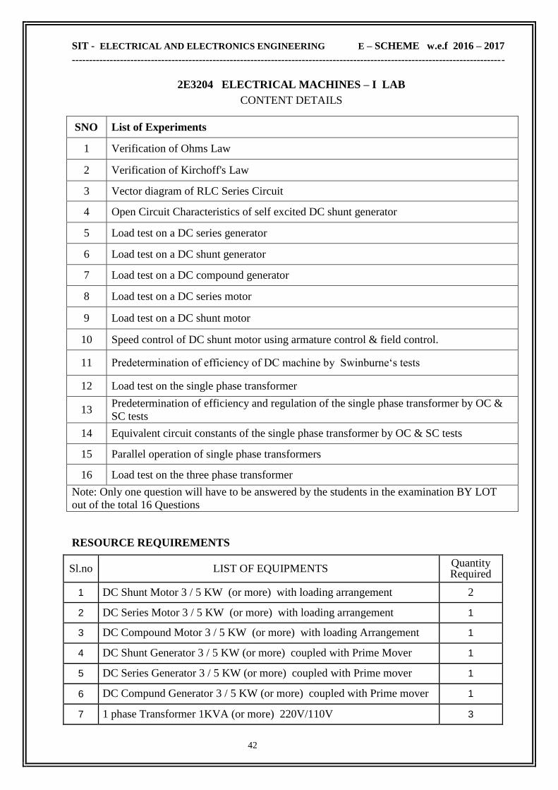
SIT - ELECTRICAL AND ELECTRONICS ENGINEERING E – SCHEME w.e.f 2016 – 2017
------------------------------------------------------------------------------------------------------------------------------
42
2E3204 ELECTRICAL MACHINES – I LAB
CONTENT DETAILS
SNO List of Experiments
1 Verification of Ohms Law
2 Verification of Kirchoff's Law
3 Vector diagram of RLC Series Circuit
4 Open Circuit Characteristics of self excited DC shunt generator
5 Load test on a DC series generator
6 Load test on a DC shunt generator
7 Load test on a DC compound generator
8 Load test on a DC series motor
9 Load test on a DC shunt motor
10 Speed control of DC shunt motor using armature control & field control.
11 Predetermination of efficiency of DC machine by Swinburne‗s tests
12 Load test on the single phase transformer
13 Predetermination of efficiency and regulation of the single phase transformer by OC &
SC tests
14 Equivalent circuit constants of the single phase transformer by OC & SC tests
15 Parallel operation of single phase transformers
16 Load test on the three phase transformer
Note: Only one question will have to be answered by the students in the examination BY LOT
out of the total 16 Questions
RESOURCE REQUIREMENTS
Sl.no LIST OF EQUIPMENTS Quantity Required
1 DC Shunt Motor 3 / 5 KW (or more) with loading arrangement 2
2 DC Series Motor 3 / 5 KW (or more) with loading arrangement 1
3 DC Compound Motor 3 / 5 KW (or more) with loading Arrangement 1
4 DC Shunt Generator 3 / 5 KW (or more) coupled with Prime Mover 1
5 DC Series Generator 3 / 5 KW (or more) coupled with Prime mover 1
6 DC Compund Generator 3 / 5 KW (or more) coupled with Prime mover 1
7 1 phase Transformer 1KVA (or more) 220V/110V 3

SIT - ELECTRICAL AND ELECTRONICS ENGINEERING E – SCHEME w.e.f 2016 – 2017
------------------------------------------------------------------------------------------------------------------------------
43
8 3 phase Transformer 1 KVA (or more) 440V/220V 1
9 1 phase Variac 15 Amps 3
10 3 phase Variac 15 Amps 1
11 Loading Rheostat 220V, 30A, Single phase loading Rheostat 2
12 Tachometer Analog / Digital type 2
13 3 point starter / 4 point starter 3
14 Rheostat – various ranges 50Ω-100Ω,1300Ω-600Ω 10
15 DC Ammeter- various ranger 0-1,0-2,0-15,0-30 Amps 10
16 DC Voltmeter- various ranges 0-75V,0-150V, 0-300V,0-600V 10
17 Wattmeter-various ranges LPF 75/150/300/600 Volts 1
18 Wattmeter-various ranges UPF 75/150/300/600 Volts 3
COURSE OUTCOME
CO1
Able to Obtain resonance of the given RLC Series circuit.
Able to Measure Single phase and Three phase ac power.
Able to Calibrate the given Ammeter and Voltmeter .
CO2
Able to Obtain Open Circuit Characteristics of self excited DC shunt generator
Able to Obtain Load characteristics of DC series generator, shunt generator and
compound generator
CO3 Able to Conduct Load test on Dc Series motor and DC Shunt motor.
Able to Control the speed of DC shunt motor.
CO4 Able to Predetermine the efficiency of DC machine by Swinburne‗s tests
Able to Conduct Load test on single phase transformer
CO5
Able to Predetermine the efficiency and regulation of the single phase transformer by
OC & SC tests
Able to understand the construction and working of Dc starters

SIT - ELECTRICAL AND ELECTRONICS ENGINEERING E – SCHEME w.e.f 2016 – 2017
------------------------------------------------------------------------------------------------------------------------------
44
2E3205 ELECTRONIC DEVICES & CIRCUITS LAB
RATIONALE To expose the students to the basic operation of the electronic equipments and helps them
to develop experimental skills for developing the electronic circuits for the required applications.
OBJECTIVES After the completion of this laboratory, the student should be able to
Draw the circuit diagrams of biasing circuit and obtain characteristics of PN
junction diode, Zener diode, JFET, UJT, SCR, DIAC, TRAIC, LDR, Photo diode
and Photo transistor, clipper clamper and voltage doubler. Draw the circuit diagrams of Rectifiers, filters, transistors, amplifier and
oscillators
Assemble / construct all the above circuits.
Test the above circuits for their performance
Analyses the above circuits
SCHEME OF INSTRUCTION & EXAMINATION
Course
Code
Instruction
Credit
Scheme Of Examinations
Hours /
week
Hours /
Term
Marks Duration
Internal End Exam Total
2E3205 4 60 2 25 75 100 3
Scheme Of Evaluation:
SLNO Description Maximum Marks
1 Circuit diagram 20
2 Connection 25
3 Execution 15
4 Output / Result 10
5 Viva Voce 05
6 TOTAL 75

SIT - ELECTRICAL AND ELECTRONICS ENGINEERING E – SCHEME w.e.f 2016 – 2017
------------------------------------------------------------------------------------------------------------------------------
45
2E3205 - ELECTRONIC DEVICES & CIRCUITS LAB
CONTENT DETAILS
SLNO List of Experiments
1 VI Characteristics of PN Junction Diode
2 VI Characteristics of Zener diode
3 Half wave with and without filter
4 Full wave rectifier with and without filter
5 Bridge Rectifier with and without filter
6 VI characteristics of Regulator using zener diode.
7 Input/output characteristics of CE Transistor
8 Frequency response of RC coupled amplifier
9 Emitter follower
10 RC phase shift oscillator.
11 Hartley and Colpitts oscillator
12 JFET characteristics
13 UJT characteristics.
14 SCR characteristics
15 DIAC and TRIAC characteristics
16 Clipper, clamper and voltage doubler.
17 LDR, Photo diode and Photo transistor characteristics.
18 Solar cell and opto coupler.
Note: Only one question will have to be answered by the students in the examination BY
LOT out of the total 18 Questions.
RESOURCE REQUIREMENTS
Sl.no LIST OF EQUIPMENTS Quantity Required
01 Regulated Power Supply 3
02 Dual RPS 2
03 Variac 3
04 Function Generator 4
05 CRO 4
06 Ammeters 12
07 Voltmeters 6
08 Digital Multimeter 6
09 Digital IC trainer kit 6
10 Half wave & Full wave rectifier kit 1
11 Bridge rectifier kit 1

SIT - ELECTRICAL AND ELECTRONICS ENGINEERING E – SCHEME w.e.f 2016 – 2017
------------------------------------------------------------------------------------------------------------------------------
46
COURSE OUTCOME
CO1
Able to Draw the circuit diagrams of biasing circuit and obtain characteristics of PN
junction diode, Zener diode, JFET, UJT, SCR, DIAC, TRAIC, LDR, Photo diode and
Photo transistor, clipper clamper and voltage doubler.
CO2 Able to Draw the circuit diagrams of Rectifiers, filters, transistors, amplifier and
oscillators
CO3 Able to Assemble / construct all the above circuits.
CO4 Able to Test the above circuits for their performance.
CO5 Able to Analyses the above circuits
12 Pi filter kit 1
13 Clipper (+ve & -ve) kit 1
14 Clamper (+ve & -ve) kit 1
15 Voltage doubler kit 1
16 CE transistor kit 1
17 RC coupled amplifier kit 1
18 RC phase shift oscillator kit 1
19 Common source amplifier kit 1
20 Emitter follower kit 1
21 Negative feedback amplifier kit 1
22 Relaxation oscillator kit 1
23 Hartley & colpitts oscillator kit 1
24 DIAC kit 1
25 TRIAC kit 1
26 LDR, Photo diode &
Photo transistor kit 1
27 Solar cell & opto coupler kit 1
28 Bread board 6
29 Soldering Iron & Tools set 2

SIT - ELECTRICAL AND ELECTRONICS ENGINEERING E – SCHEME w.e.f 2016 – 2017
------------------------------------------------------------------------------------------------------------------------------
47
2E3402 C++ PROGRAMMING LAB
RATIONALE Computers are now-a-days necessary in human routine life. At each and every stage, we find its
importance. In technical side, engineers are using computers extensively to solve their design
problems. Here, an attempt is made to generate different skills in C++ programming like the
concept of function over loading, classes and objects, constructers, operator over loading, virtual
function and writing and reading the data from a file.
OBJECTIVES
After the completion of this laboratory, the student should be able to Write a program in function over loading.
Write a program in classes and objects.
Write a program in constructers and operator over loading.
Write a program in virtual function and writing and reading the data from a file.
SCHEME OF INSTRUCTION & EXAMINATION
Course
Code
Instruction
Credit
Scheme Of Examinations
Hours /
week
Hours /
Term
Marks Duration
Internal End Exam Total
2E3205 6 90 4 25 75 100 3
Scheme Of Evaluation:
SNO Description Maximum
Marks
1 Aim & Procedure 10
2 Program 25
3 Execution 25
4 Result [ Input & Output ] 10
5 Viva Voce 05
6 TOTAL 75

SIT - ELECTRICAL AND ELECTRONICS ENGINEERING E – SCHEME w.e.f 2016 – 2017
------------------------------------------------------------------------------------------------------------------------------
48
2E3402 - C++ PROGRAMMING LAB
CONTENT DETAILS
SLNO List of Experiments
1 Program to read n numbers and display the largest value
2 Program to generate Fibonacci series
3 Program for addition /subtraction of two matrices.
4 Program to multiply two matrices.
5 Program to find the sum of numbers in a list
6 Program for sorting the name in alphabetical order.
7 Program to arrange the given set of numbers in ascending order.
8 Program to find the roots of quadratic equation
9 Program to perform arithmetic operation depending upon user‗s choice
10 Program to convert lower case to upper case and vice versa
11 Program to illustrate the concept of function over loading
12 Program to illustrate the concepts of classes and objects
13 Program to add two complex numbers using constructers.
14 Program to illustrate the concept of operator over loading.
15 Program to convert one data type to another data type.
16 Program to illustrate the concept of virtual function.
17 Program to count number of characters, words & lines in a text.
18 Program to define a class string, use overload operator to compare two strings.
19 Write a function to swap the values of to variables to illustrate the concept of
pass by reference. 20 Program to use a single file for writing and reading the data
Note: Only one question will have to be answered by the students in the examination BY LOT
out of the total 20 Questions.
LIST OF EQUIPMENTS AND THE QUANTITY REQUIRED
(FOR A BATCH OF 30 STUDENTS)
OPERATING SYSTEM : WINDOWS XP OR WINDOWS VISTA OR WINDOWS 7 /
LINUX
OFFICE PACKAGE : MICROSOFT OFFICE 2000 OR OFFICE 2003 OR
OFFICE 2007/OPEN OFFICE
HARDWARE REQUIREMENTS :
DESKTOP COMPUTER SYSTEM
WITH LATEST CONFIGURATION 30 NOS
POWER BACKUP (UPS)
10 KVA
LASER PRINTER 3 NOS
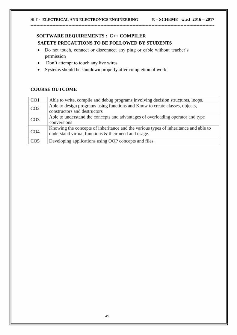
SIT - ELECTRICAL AND ELECTRONICS ENGINEERING E – SCHEME w.e.f 2016 – 2017
------------------------------------------------------------------------------------------------------------------------------
49
SOFTWARE REQUIREMENTS : C++ COMPILER SAFETY PRECAUTIONS TO BE FOLLOWED BY STUDENTS
Do not touch, connect or disconnect any plug or cable without teacher‘s
permission
Don‘t attempt to touch any live wires
Systems should be shutdown properly after completion of work
COURSE OUTCOME
CO1 Able to write, compile and debug programs involving decision structures, loops.
CO2 Able to design programs using functions and Know to create classes, objects,
constructors and destructors
CO3 Able to understand the concepts and advantages of overloading operator and type
conversions
CO4 Knowing the concepts of inheritance and the various types of inheritance and able to
understand virtual functions & their need and usage.
CO5 Developing applications using OOP concepts and files.

SIT - ELECTRICAL AND ELECTRONICS ENGINEERING E – SCHEME w.e.f 2016 – 2017
------------------------------------------------------------------------------------------------------------------------------
50
TERM - IV
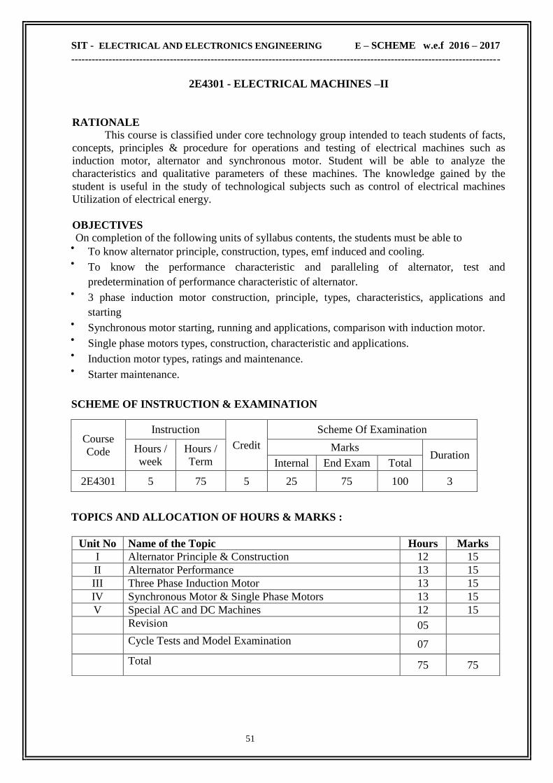
SIT - ELECTRICAL AND ELECTRONICS ENGINEERING E – SCHEME w.e.f 2016 – 2017
------------------------------------------------------------------------------------------------------------------------------
51
2E4301 - ELECTRICAL MACHINES –II
RATIONALE This course is classified under core technology group intended to teach students of facts,
concepts, principles & procedure for operations and testing of electrical machines such as
induction motor, alternator and synchronous motor. Student will be able to analyze the
characteristics and qualitative parameters of these machines. The knowledge gained by the
student is useful in the study of technological subjects such as control of electrical machines
Utilization of electrical energy.
OBJECTIVES On completion of the following units of syllabus contents, the students must be able to
To know alternator principle, construction, types, emf induced and cooling.
To know the performance characteristic and paralleling of alternator, test and
predetermination of performance characteristic of alternator.
3 phase induction motor construction, principle, types, characteristics, applications and
starting
Synchronous motor starting, running and applications, comparison with induction motor.
Single phase motors types, construction, characteristic and applications.
Induction motor types, ratings and maintenance.
Starter maintenance.
SCHEME OF INSTRUCTION & EXAMINATION
Course
Code
Instruction
Credit
Scheme Of Examination
Hours /
week
Hours /
Term
Marks Duration
Internal End Exam Total
2E4301 5 75 5 25 75 100 3
TOPICS AND ALLOCATION OF HOURS & MARKS :
Unit No Name of the Topic Hours Marks
I Alternator Principle & Construction 12 15
II Alternator Performance 13 15
III Three Phase Induction Motor 13 15
IV Synchronous Motor & Single Phase Motors 13 15
V Special AC and DC Machines 12 15
Revision 05
Cycle Tests and Model Examination 07
Total 75 75

SIT - ELECTRICAL AND ELECTRONICS ENGINEERING E – SCHEME w.e.f 2016 – 2017
------------------------------------------------------------------------------------------------------------------------------
52
2E4301 - ELECTRICAL MACHINES – II
CONTENT DETAILS
UNIT I : ALTERNATOR PRINCIPLE & CONSTRUCTION
1.1 Alternator Principle & Construction: Basic Principle & Requirements of alternator –
Rotating Field System & Rotating Armature System -Advantages of Rotating Field (Stationary
Armature) System -Types of Rotor - Salient Pole rotor - Non Salient pole rotor -
Construction -Salient Pole -Non Salient Pole -Turbo Alternator
1.2 Windings & EMF equation: Types of armature windings (No winding diagram) - Single
layer- Double layer -Lap & Concentric winding -Integral slot winding - Fractional Slot winding -
Phase spread -Pitch Factor -Distribution factor-EMF equation of alternators-Simple problems-
Effect of Pitch factor on EMF-Advantages of chorded pitch winding - Effect of pitch
factor on harmonics-Methods of obtaining Sine wave in salientpole & non salientpole alternators
1.3 Cooling of alternators: Different methods -Horizontal, vertical -Natural & forced cooling -
Hydrogen Cooling & its Merits.
UNIT II : ALTERNATOR PERFORMANCE
2.1Alternator Performance: Alternator on No load -Effective Armature resistance –Leakage
reactance -Reactance due to armature reaction– Synchronous reactance - Synchronous
impedance –Causes for Voltage drop in alternators (Simple problems)– Vector diagram of
alternators on load (for lag, lead and unity power factors)
2.2 Testing : Open circuit & Short circuit test –Determination of regulation by direct load
test - Pre-determination of Regulation by EMF method, MMF method, ZPF method
2.3 Parallel operation of alternators : Necessity of Synchronization -Advantages -Methods –
Dark lamp method -Bright Lamp method -Synchroscope method - Synchronizing current,
Synchronizing power, Synchronizing torque -Effect of change in excitation of alternators in
parallel -Load sharing of two alternators (Simple problems)
UNIT III : SYNCHRONOUS MOTOR & SINGLE PHASE MOTORS
3.1 Synchronous Motor: Basic theory - Reasons for not self starting - Different methods of
starting Synchronous motor - Vector diagram on No load (Simple problems) - V Curve and
inverted V curve for different excitation at constant input power -Effect of change in
excitation
3.2 Power Factor Improvement: Power factor improvement using Synchronous motor
(Simple problems) Hunting -Applications of Synchronous Motors –Comparison between
Synchronous motor & Three phase induction motor.
3.3 Single Phase Induction Motor: Double Field Revolving theory for Single phase Induction
Motor -Construction, Principle of working & applications of Split Phase motors, Capacitor type
motors, Shaded pole motor, Universal motor, Repulsion motor.
UNIT IV : THREE PHASE INDUCTION MOTOR
4.1 principle & construction: rotating magnetic field produced by 2 phase and 3 phase system -
principle of operation of 3 phase induction motor - construction - slip and slip frequency -
comparison between cage and slip ring induction motors
4.2 Characteristics of motor : starting torque derivation -condition for maximum starting
torque - torque under running condition -torque in synchronous watts -slip-torque characteristics
- relationship between starting torque and full load torque (no problems) - development of phasor
diagram of three phase induction motor no load test and blocked rotor test - development of
approximate equivalent circuit -development of circle diagram -determination of maximum
torque, slip etc., (no problems) - speed control by injected e.m.f. method, rotor resistance
method

SIT - ELECTRICAL AND ELECTRONICS ENGINEERING E – SCHEME w.e.f 2016 – 2017
------------------------------------------------------------------------------------------------------------------------------
53
4.3 starters & other induction motors: starters for induction motor -direct on line starter, rotor
resistance starter -auto transformer starter - star delta starter- soft starters , crawling, cogging
in induction motor. -construction, working principle and applications of double cage motor,
linear induction motor and induction generator
UNIT V : SPECIAL AC AND DC MACHINES
5.1 SPECIAL AC MACHINES : Permanent magnet Synchronous motors – Construction and
performance – Advantages – Applications –Synchros – Constructional features – Control
Transmitter – Control receiver - Applications of synchros – A.C. Servo motors – Two phase
A.C. Servo motor – Linear induction motor
5.2 SPECIAL DC MACHINES : Permanent Magnet D.C. Motor – Construction–Working
principle – Speed control – Advantages – Applications – Servo motors – D.C. Servomotors –
Stepper motors – Variable reluctance stepper motor – Permanent magnet stepper motor.
TEXT BOOK
Sl.No. Title Author Publisher
1 A text book of Electrical Technology
23rd Re-edition, 2006
B.L.Theraja
A.L. Theraja
S.Chand & Co
New Delhi
REFERENCE BOOKS
Sl.No. Title Author Publisher
1 Electrical machines
4th Edition, 2014 S.K.Bhattacharya
Tata -Mc Graw Hill , New
Delhi
2 Operation and Maintenance of
Electrical Machines B.V.S. Rao
Khanna Publishers, New
Delhi
3 Electrical Technology
10th Edition, 2010 Edward Hughes
Addision -Wesley
International Student Ed.
4 Performance and design of AC
machines, 3rd Edition 2002 M.G.Say
CBS Publication,
New Delhi
ONLINE RESOURCES
www.nptel.ac.in/courses/108106072/
www.electrical4u.com/alternator-or-synchronous-generator/
www.electrical4u.com/electrical-motor-types-classification-and-history-of-motor/
www.electrical4u.com/electrical-power-transformer-definition-and-types-of-transformer/
COURSE OUTCOME
CO1
Able to know alternator principle, construction, types, emf induced and cooling.
Able to know the performance characteristic and paralleling of alternator, test and
predetermination of performance characteristic of alternator.
CO2 Able to understand 3 phase induction motor construction, principle, types,
characteristics, applications and starting
CO3 Able to understand Synchronous motor starting, running and applications, comparison
with induction motor.
CO4 Knowing the concepts of Single phase motors types, construction, characteristic and
applications.
CO5 Knowing the concepts of Induction motor types, ratings and maintenance and Starter
maintenance.
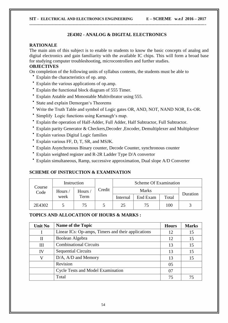
SIT - ELECTRICAL AND ELECTRONICS ENGINEERING E – SCHEME w.e.f 2016 – 2017
------------------------------------------------------------------------------------------------------------------------------
54
2E4302 - ANALOG & DIGITAL ELECTRONICS
RATIONALE The main aim of this subject is to enable to students to know the basic concepts of analog and
digital electronics and gain familiarity with the available IC chips. This will form a broad base
for studying computer troubleshooting, microcontrollers and further studies.
OBJECTIVES On completion of the following units of syllabus contents, the students must be able to
Explain the characteristics of op. amp.
Explain the various applications of op.amp.
Explain the functional block diagram of 555 Timer.
Explain Astable and Monostable Multivibrator using 555.
State and explain Demorgan‗s Theorems
Write the Truth Table and symbol of Logic gates OR, AND, NOT, NAND NOR, Ex-OR.
Simplify Logic functions using Karnaugh‗s map.
Explain the operation of Half-Adder, Full Adder, Half Subtractor, Full Subtractor.
Explain parity Generator & Checkers,Decoder ,Encoder, Demultiplexer and Multiplexer
Explain various Digital Logic families
Explain various FF, D, T, SR, and MSJK.
Explain Asynchronous Binary counter, Decode Counter, synchronous counter
Explain weighted register and R-2R Ladder Type D/A convertor
Explain simultaneous, Ramp, successive approximation, Dual slope A/D Converter
SCHEME OF INSTRUCTION & EXAMINATION
Course
Code
Instruction
Credit
Scheme Of Examination
Hours /
week
Hours /
Term
Marks Duration
Internal End Exam Total
2E4302 5 75 5 25 75 100 3
TOPICS AND ALLOCATION OF HOURS & MARKS :
Unit No Name of the Topic Hours Marks
I Linear ICs: Op-amps, Timers and their applications 12 15
II Boolean Algebra 12 15
III Combinational Circuits 13 15
IV Sequential Circuits 13 15
V D/A, A/D and Memory 13 15
Revision 05
Cycle Tests and Model Examination 07
Total 75 75

SIT - ELECTRICAL AND ELECTRONICS ENGINEERING E – SCHEME w.e.f 2016 – 2017
------------------------------------------------------------------------------------------------------------------------------
55
2E4302 - ANALOG & DIGITAL ELECTRONICS
CONTENT DETAILS
UNIT I : . LINEAR ICS: OP-AMPS, TIMERS AND THEIR APPLICATIONS
1.1 Op-amps : Operational amplifier -Ideal Op.Amp -Block diagram and characteristics -
(Minus input follows Plus input and No current through Minus and Plus input) -op-amp
parameters -CMRR -Slew rate -Virtual ground
1.2 Applications of opamp : Inverting amplifier - Summing amplifier -Non inverting
amplifier -Voltage follower -Comparator -Zero crossing detector - Integrator– Differentiator–
Op.Amp Specifications.
1.3 Timer : 555 Timer - Functional Block diagram -Astable, Monostable and Schmitt Trigger
. IC voltage regulator -3 pin IC regulators -78 xx, 79xx, LM317
UNIT II : BOOLEAN ALGEBRA
2.1 Number systems & Boolean Algebra : Decimal -Binary -Octal -Hexadecimal -BCD -
Conversion from one number system to other –Boolean Algebra -Basic laws and
Demorgan‗s Theorems
2.2 Logic gates : OR -AND -NOT -NOR -NAND -EXOR : Symbols, Truth table and Boolean
expression -Realization of gates using universal gates NAND and NOR
2.3 Simplification Of Boolean Expressions : Problems using 2, 3, and 4 variables -Boolean
expression for outputs -Simplification of Boolean expression using karnaugh map (upto 4
variable)- Constructing logic circuits for the Boolean expressions.
UNIT III : COMBINATIONAL LOGIC
3.1 Arithmetic circuits : Binary addition -Binary Subtraction -1‗s complement and 2‗s
complement -Signed binary numbers -Half adder -Full adder -Half subtractor -Full subtractor
3.2 Functional Logic circuits : Parity Generator and checker– Digital comparator -
Arithmetic Logic Unit -Decoder -3 to 8 decoder -BCD to seven segment decoder - Encoder
- Multiplexer –Demultiplexer -Digital Logic families
3.3 Digital Logic families : TTL NAND – CMOS NOR -LS series - Fan in - Fan out -
Propagation delay - Noise immunity for the above families.- Tristate Logic.
UNIT IV : SEQUENTIAL LOGIC
4.1 Flip-flops : RS -D -T -JK -Master Slave Flip Flops -Edge triggered FF
4.2 Counters : Asynchronous Binary Counter -Decade counter -Mod n counter -Up/ Down
Counter - Presettable counter -Ring counter -Johnson counter -Synchronous counter
4.3 Shift register : 4 bit shift register -Serial in Serial out -Serial in Parallel out -Parallel in
serial out - Parallel in Parallel out.
UNIT V : D/A, A/D AND MEMORY
5.1 D/A Converter : Basic concepts -Weighted Resistor D/A converter -R-2R Ladder D/A
converter -Specification of DAC IC.
5.2 A/D Converter : Analog to digital conversion using Ramp method –Successive
approximation method - voltage to frequency converter - Frequency to voltage converter
specification of A/D converter.
5.3 Memory : Static Memory - Dynamic Memory - Static Memory organization in terms of
address lines, control lines and data lines - Expanding memory (say 8k to 16k) SDRAM -
DDR RAM.
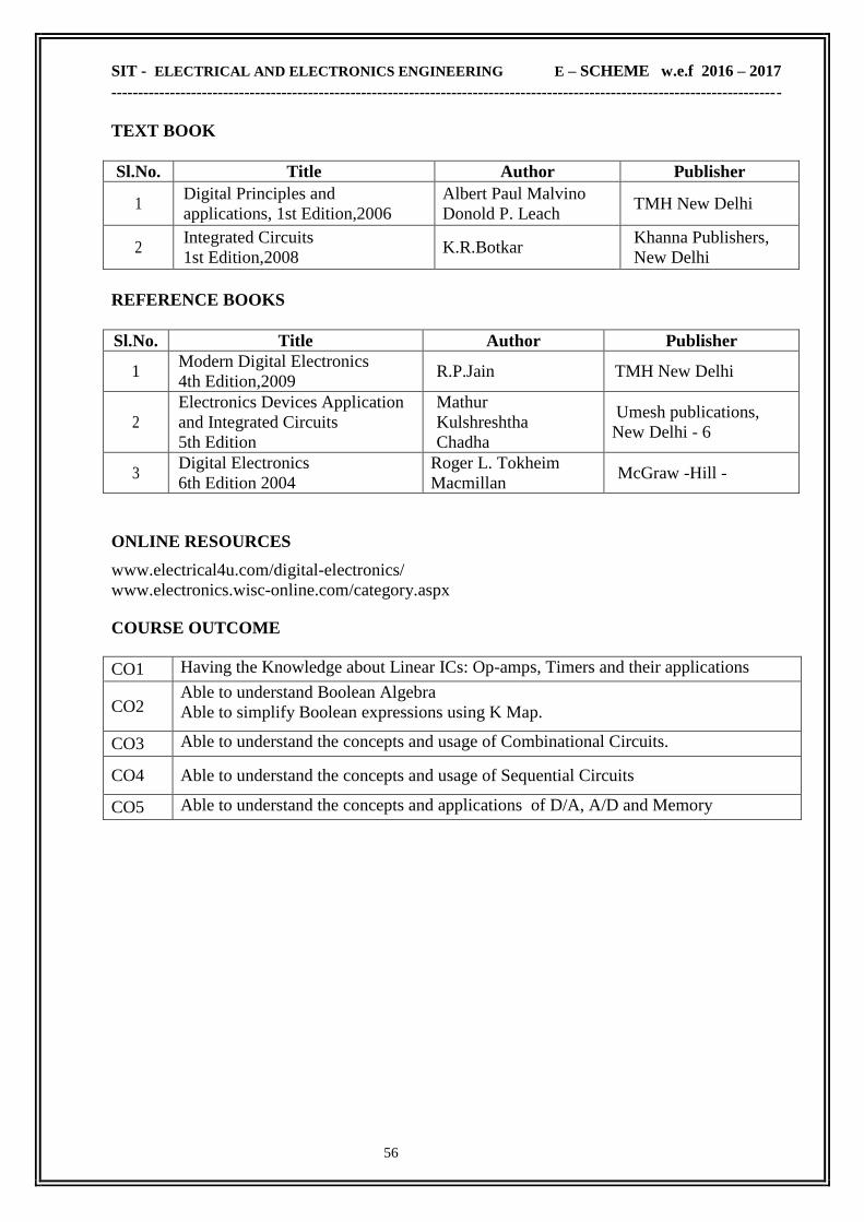
SIT - ELECTRICAL AND ELECTRONICS ENGINEERING E – SCHEME w.e.f 2016 – 2017
------------------------------------------------------------------------------------------------------------------------------
56
TEXT BOOK
Sl.No. Title Author Publisher
1 Digital Principles and
applications, 1st Edition,2006
Albert Paul Malvino
Donold P. Leach TMH New Delhi
2 Integrated Circuits
1st Edition,2008 K.R.Botkar
Khanna Publishers,
New Delhi
REFERENCE BOOKS
Sl.No. Title Author Publisher
1 Modern Digital Electronics
4th Edition,2009 R.P.Jain TMH New Delhi
2
Electronics Devices Application
and Integrated Circuits
5th Edition
Mathur
Kulshreshtha
Chadha
Umesh publications,
New Delhi - 6
3 Digital Electronics
6th Edition 2004
Roger L. Tokheim
Macmillan McGraw -Hill -
ONLINE RESOURCES
www.electrical4u.com/digital-electronics/
www.electronics.wisc-online.com/category.aspx
COURSE OUTCOME
CO1 Having the Knowledge about Linear ICs: Op-amps, Timers and their applications
CO2 Able to understand Boolean Algebra
Able to simplify Boolean expressions using K Map.
CO3 Able to understand the concepts and usage of Combinational Circuits.
CO4 Able to understand the concepts and usage of Sequential Circuits
CO5 Able to understand the concepts and applications of D/A, A/D and Memory

SIT - ELECTRICAL AND ELECTRONICS ENGINEERING E – SCHEME w.e.f 2016 – 2017
------------------------------------------------------------------------------------------------------------------------------
57
2E4206 - MEASUREMENTS AND INSTRUMENTATION
RATIONALE
The course ―Electrical Measurement And Measuring Instruments‖ is important in the
field of electrical engineering. This course deals with the methods of measuring voltage,
current, power, energy, frequency, power factor & parameters like resistance, inductance and
capacitance and constructional detail and principle of operation of the instruments used for
such measurements. Also it provides the methods to extend the range of low range
instruments to measure higher values. The detailed classification of all instruments used for
the above measurement is dealt.
OBJECTIVES
On completion of the following units of syllabus contents, the students must be able to Understand the basic concepts on measuring system and definition of important terms,
Know the various analog instruments used to measure voltage, current and resistance
and their principle of working, construction and applications.
Know the construction, working and applications of Cathode Ray Oscilloscope
Know the construction, working and applications of Wattmeters and Energy Meters
Understand the concept of Digital meters.
Know the special instruments like MD indicator, trivector meter, synchroscope, etc.
Understand Basic transducers and their working.
SCHEME OF INSTRUCTION & EXAMINATION
Course
Code
Instruction
Credit
Scheme Of Examination
Hours /
week
Hours /
Term
Marks Duration
Internal End Exam Total
2E4206 5 75 5 25 75 100 3
TOPICS AND ALLOC ATION OF HOURS & MARKS
Unit No Name of the Topic Hours Marks
I Characteristics Of Instruments and CRO
12 15
II Measurement Of Current, Voltage And Resistance
13 15
III Measurement Of Power And Energy
13 15
IV Special Instruments
13 15
V Principle Of Instrumentation 12 15
Revision 03
Cycle Tests and Model Examination 07
Total 75 75

SIT - ELECTRICAL AND ELECTRONICS ENGINEERING E – SCHEME w.e.f 2016 – 2017
------------------------------------------------------------------------------------------------------------------------------
58
2E4206 - MEASUREMENTS AND INSTRUMENTATION
CONTENT DETAILS
UNIT I : CHARACTERISTICS AND CLASSIFICATION OF INSTRUMENTS
1.1 Definition & Classification: Definition of True value -accuracy -precision -errors -
correction - sensitivity -resolution -instrument efficiency. Classification of instruments -
Absolute and secondary instruments -indicating, integrating and recording instruments -
Effects utilized in instruments
1.2 Operating forces: Deflecting, controlling and damping forces– control system -
comparison of spring and gravity control -different types of damping systems - constructional
details of supports - balancing -torque weight ratio.
1.3 CRO: Block diagram of a general purpose CRO - Functions of each block – Dual trace and
dual beam CRO - Storage oscilloscope - Applications of CRO
UNIT II : MEASUREMENT OF CURRENT, VOLTAGE AND RESISTANCE
2.1 MC and MI Instruments: Constructional details and working of permanent magnet
moving coil meters - constructional details and working of moving iron (Attraction and
repulsion) meters as ammeters and voltmeters. Extension of instrument range by shunts and
multipliers -problems.
2.2 Instrument transformers: Principle of working -connection in a circuit -rating -ratio and
phase angle error (definition and formula only) -Effect of sudden opening of secondary of CT.-
Introduction to optical instrument transformers
2.3 Measurement of resistance: Classification of Resistances (low, medium and high) -
construction and working principle of shunt and series ohmmeters, Construction, working and
applications of Megger and multi meter.
UNIT III : MEASUREMENT OF POWER AND ENERGY
3.1 Watt meters: Classification of watt meters - dynamometer type wattmeter- construction -
theory of operation - low p.f. Wattmeter -two element, three-phase wattmeter. Maximum
demand (M.D). indicator.
3.2 Energy Meter: Construction principle and working of static type energy meters - smart
meters - integrated measuring digital instruments for measuring electrical power in KW,
KVA, KVAR & KWh. use of CT and PT for energy measurement.
3.3 Power factor Meter: Construction - principle of working of dynamometer type power factor
meter - single phase and three phase.
UNIT IV : SPECIAL INSTRUMENTS 4.1 Frequency meters: principle and working of Weston frequency meter - - Block diagram of
digital frequency meter - advantages and applications.- Block diagram of digital voltmeter -
advantages and applications.
4.2 Synchroscope: Construction -working of Weston synchroscope. Phase sequence meter:
Construction - principle of working of rotating type Indicator.
4.3 Bridges: Anderson bridge for measurement of inductance, Schering bridge for measurement
of capacitance (No derivation, formula under balanced condition only). Cable fault location -
Murray and Varley loop tests.
4.4 Recorders: Construction, working and applications of X Y recorder and Strip chart recorder
UNIT V : PRINCIPLE OF INSTRUMENTATION (Qualitative treatment only)
5.1 Transducers: Primary and secondary transducers -active and passive transducers - electrical
transducers - types - advantages of electrical transducers over mechanical transducers - Analog
and Digital transducers - Comparison between Analog & Digital transducers -Block diagram of
instrumentation system - Use of computers in process control

SIT - ELECTRICAL AND ELECTRONICS ENGINEERING E – SCHEME w.e.f 2016 – 2017
------------------------------------------------------------------------------------------------------------------------------
59
5.2 Resistive, Inductive & Capacitive Transducers: Resistive transducer – potentiometers -
Measurement of Temperature - Resistance Temperature Detector - Thermocouple - Thermistor -
Strain gauge for the measurement of pressure. Inductive transducer - types -applications -
measurement of displacement using inductive transducer (LVDT). Capacitive transducers - types
- applications – measurement of liquid level using capacitive transducer.
TEXT BOOK
Sl.No. Title Author Publisher
1
A course in electrical and electronic
measurements and instrumentation
Reprint -2015
A.K.Sawhney
Puneet Sawhney
Dhanpat Rai & Co.,
(P) Ltd., New Delhi
REFERENCE BOOKS
Sl.No. Title Author Publisher
1 Electronic instrumentation
3rd Edition -2010 HS Kalsi Tata McGraw Hill,New Delhi
2
Modern Electronic
Instrumentation and
measurement Techniques
Albert D.Heifrick
William David
Cooper
Learning Materials Centre,
ISTE,New Delhi
3
A course in electrical and
electronic measurements and
instrumentation
Umesh Sinha Satya Prakashan,New Delhi
ONLINE RESOURCES
www.electrical-engineering-portal.com/download-center/books-and-guides/
www.vssut.ac.in/lecture_notes/lecture1423813026.pdf
COURSE OUTCOME
CO1 Able to Understand the basic concepts and definition of important terms.
CO2 Able to Know the various analog instruments used to measure voltage, current and
resistance and their principle of working, construction and applications.
CO3 Able to Know the construction, working and applications of CRO
CO4 Able to Know the construction, working and applications of Wattmeters and Energy
Meters, Digital meters, Bridges and Recorders
CO5 Able to understand Basic transducers and their working

SIT - ELECTRICAL AND ELECTRONICS ENGINEERING E – SCHEME w.e.f 2016 – 2017
------------------------------------------------------------------------------------------------------------------------------
60
2E4303 - ELECTRICAL MACHINES - II LAB
RATIONALE In Electrical Machine-II, the students have been imparted with the theoretical knowledge
of different electrical machines. Keeping in view of practical knowledge the syllabus of
Electrical Machines Lab has been preferred. So that it may bring boldness and confidence in the
students regarding the actual working of Electrical machines.
OBJECTIVES After the completion of this laboratory, the student should be able to
Run the alternator and to determine the regulation by synchronous impedance method.
Determine the load characteristic of Single Phase and three Phase alternator.
Run and synchronize two alternators by lamp & synchroscope method.
Determine ‗V‘ and ‗Inverted-V‘ curve of 3 phase synchronous motor.
Run and conduct load test on Single Phase I.M., 3 Phase Cage I.M. and Slipring I.M.
Draw equivalent circuit of an IM, by conducting No load & Blocked rotor test.
Develop Circle diagram of three phase Induction motor
Determine the unknown inductance by using Anderson bridge
Determine the unknown capacitance by using Schering bridge
Calibrate the given Wattmeter, Single Phase energy meter and 3 Phase energy meter.
Measure the earth resistance using earth tester kit.
Measure the displacement using LVDT.
Calibrate the load cell.
SCHEME OF INSTRUCTION & EXAMINATION
Course
Code
Instruction
Credit
Scheme Of Examination
Hours /
week
Hours /
Term
Marks Duration
Internal End Exam Total
2E4303 6 90 3 25 75 100 3
Scheme Of Evaluation:
SLNO Description Maximum Marks
1 Circuit diagram 20
2 Connections and proceeding the Experiment 25
3 Reading/calculation/graph/result 25
4 Viva Voce 05
5 TOTAL 75
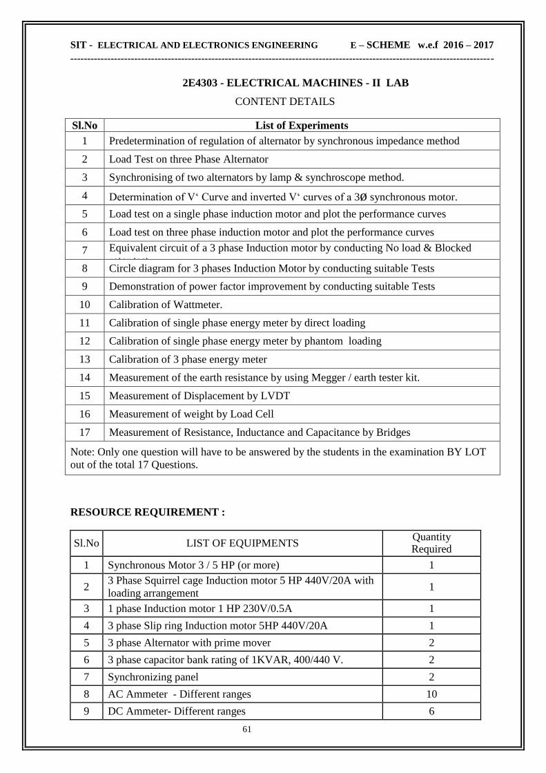
SIT - ELECTRICAL AND ELECTRONICS ENGINEERING E – SCHEME w.e.f 2016 – 2017
------------------------------------------------------------------------------------------------------------------------------
61
2E4303 - ELECTRICAL MACHINES - II LAB
CONTENT DETAILS
Sl.No List of Experiments
1 Predetermination of regulation of alternator by synchronous impedance method
2 Load Test on three Phase Alternator
3 Synchronising of two alternators by lamp & synchroscope method.
4 Determination of V‗ Curve and inverted V‗ curves of a 3ø synchronous motor.
5 Load test on a single phase induction motor and plot the performance curves
6 Load test on three phase induction motor and plot the performance curves
7 Equivalent circuit of a 3 phase Induction motor by conducting No load & Blocked
rotor test 8 Circle diagram for 3 phases Induction Motor by conducting suitable Tests
9 Demonstration of power factor improvement by conducting suitable Tests
10 Calibration of Wattmeter.
11 Calibration of single phase energy meter by direct loading
12 Calibration of single phase energy meter by phantom loading
13 Calibration of 3 phase energy meter
14 Measurement of the earth resistance by using Megger / earth tester kit.
15 Measurement of Displacement by LVDT
16 Measurement of weight by Load Cell
17 Measurement of Resistance, Inductance and Capacitance by Bridges
Note: Only one question will have to be answered by the students in the examination BY LOT
out of the total 17 Questions.
RESOURCE REQUIREMENT :
Sl.No LIST OF EQUIPMENTS Quantity Required
1 Synchronous Motor 3 / 5 HP (or more) 1
2 3 Phase Squirrel cage Induction motor 5 HP 440V/20A with
loading arrangement 1
3 1 phase Induction motor 1 HP 230V/0.5A 1
4 3 phase Slip ring Induction motor 5HP 440V/20A 1
5 3 phase Alternator with prime mover 2
6 3 phase capacitor bank rating of 1KVAR, 400/440 V. 2
7 Synchronizing panel 2
8 AC Ammeter - Different ranges 10
9 DC Ammeter- Different ranges 6

SIT - ELECTRICAL AND ELECTRONICS ENGINEERING E – SCHEME w.e.f 2016 – 2017
------------------------------------------------------------------------------------------------------------------------------
62
10 AC Voltmeter - Different ranges 10
11 DC Voltmeter - Different ranges 6
12 Wattmeter - Different ranges 6
13 Wheatstone bridge 1
14 Anderson Bridge 1
15 Schering Bridge 1
16 1 Phase Energy meter Calibration Induction Type 1
17 3 Phase Energy meter Calibration Induction Type 1
18 Earth Resistance Kit ( Megger) 2
19 LVDT Kit to measure Displacement 1
20 Load Cell kit with Load arrangement 1
21 Tachometer Analog / Digital 2
22 Synchroscope 1
23 Frequency meter 2
24 Power Factor meter 2
25 Single phase R.S.S meter 1
26 3 phase R.S.S meter 1
COURSE OUTCOME
CO1 Able to determine the load characteristic of Single Phase and three Phase alternator.
Able to run and synchronize two alternators by lamp & synchroscope method.
CO2
Able to determine ‗V‘ and ‗Inverted-V‘ curve of 3 ø synchronous motor.
Able to run and conduct load test on 1 ø I.M.,3 ø Phase Cage I.M. and Slipring I.M.
Able to draw equivalent circuit of an IM, by conducting No load & Blocked rotor test.
CO3
Able to develop Circle diagram of three phase Induction motor
Able to determine the unknown inductance by using Anderson bridge
Able to determine the unknown capacitance by using Schering bridge .
CO4 Able to calibrate the given Wattmeter, 1 ø energy meter and 3 ø energy meter.
Able to measure the earth resistance using earth tester kit.
CO5 Able to measure the displacement using LVDT.
Able to calibrate the load cell.

SIT - ELECTRICAL AND ELECTRONICS ENGINEERING E – SCHEME w.e.f 2016 – 2017
------------------------------------------------------------------------------------------------------------------------------
63
2E4304 - ANALOG & DIGITAL ELECTRONICS LAB
RATIONALE In this practical work, the student‗s knowledge about the Analog and Digital systems.
They will become capable of developing and implementing Digital Circuits. They will also be
able to acquire skills of operating A/D and D/A converters, counters and display system.
OBJECTIVES After the completion of this laboratory, the student should be able to
Build and test various applications of operational amplifiers.
Familiarized with use of Digital ICs.
Assemble and study the various multivibrator circuit and voltage regulator circuits.
Construct and study different counter circuits using IC‗s.
Know A/D & D/A conversions.
SCHEME OF INSTRUCTION & EXAMINATION
Course
Code
Instruction
Credit
Scheme Of Examination
Hours /
week
Hours /
Term
Marks Duration
Internal End Exam Total
2E4304 4 60 2 25 75 100 3
Scheme Of Evaluation:
SLNO Description Maximum Marks
1 Circuit diagram 25
2 Connection 15
3 Execution 25
4 Result 05
5 Viva Voce 05
6 TOTAL 75
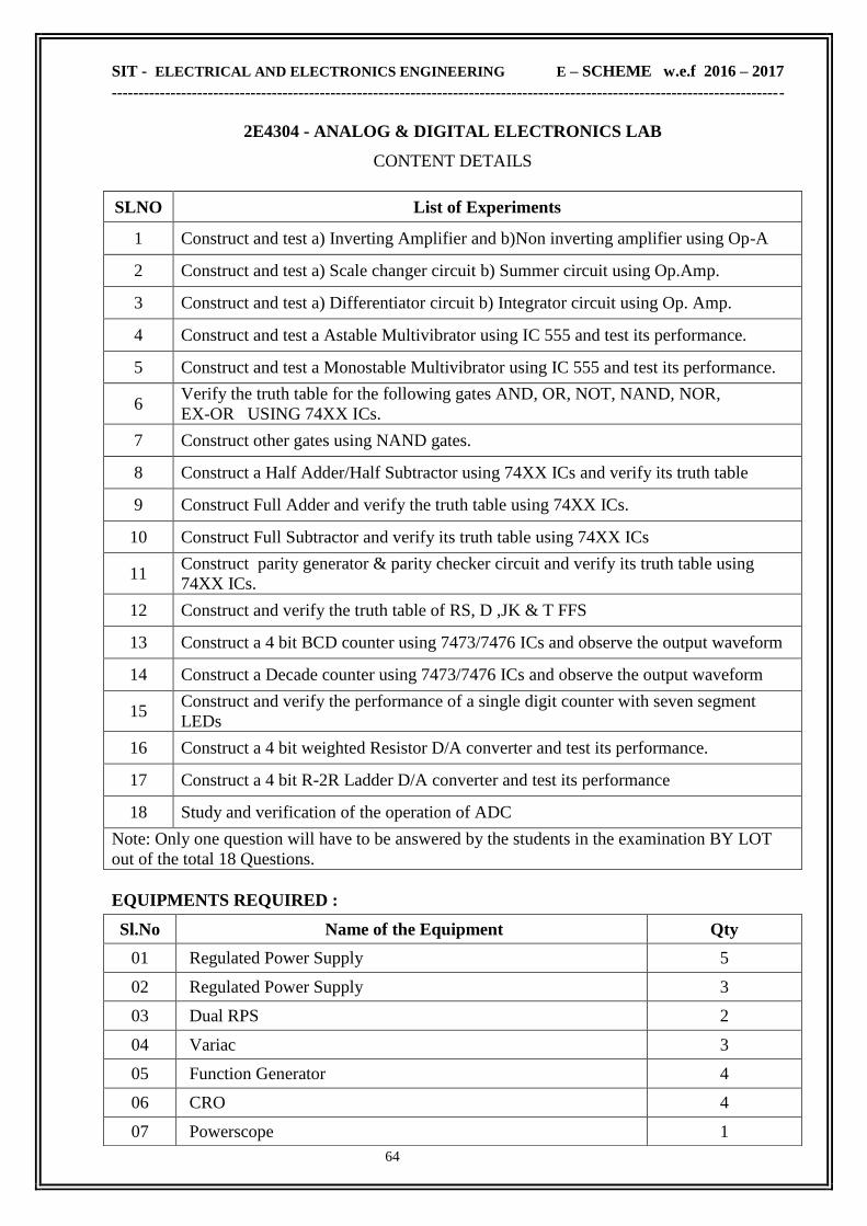
SIT - ELECTRICAL AND ELECTRONICS ENGINEERING E – SCHEME w.e.f 2016 – 2017
------------------------------------------------------------------------------------------------------------------------------
64
2E4304 - ANALOG & DIGITAL ELECTRONICS LAB
CONTENT DETAILS
SLNO List of Experiments
1 Construct and test a) Inverting Amplifier and b)Non inverting amplifier using Op-A
2 Construct and test a) Scale changer circuit b) Summer circuit using Op.Amp.
3 Construct and test a) Differentiator circuit b) Integrator circuit using Op. Amp.
4 Construct and test a Astable Multivibrator using IC 555 and test its performance.
5 Construct and test a Monostable Multivibrator using IC 555 and test its performance.
6 Verify the truth table for the following gates AND, OR, NOT, NAND, NOR,
EX-OR USING 74XX ICs.
7 Construct other gates using NAND gates.
8 Construct a Half Adder/Half Subtractor using 74XX ICs and verify its truth table
9 Construct Full Adder and verify the truth table using 74XX ICs.
10 Construct Full Subtractor and verify its truth table using 74XX ICs
11 Construct parity generator & parity checker circuit and verify its truth table using
74XX ICs.
12 Construct and verify the truth table of RS, D ,JK & T FFS
13 Construct a 4 bit BCD counter using 7473/7476 ICs and observe the output waveform
14 Construct a Decade counter using 7473/7476 ICs and observe the output waveform
15 Construct and verify the performance of a single digit counter with seven segment
LEDs
16 Construct a 4 bit weighted Resistor D/A converter and test its performance.
17 Construct a 4 bit R-2R Ladder D/A converter and test its performance
18 Study and verification of the operation of ADC
Note: Only one question will have to be answered by the students in the examination BY LOT
out of the total 18 Questions.
EQUIPMENTS REQUIRED :
Sl.No Name of the Equipment Qty
01 Regulated Power Supply 5
02 Regulated Power Supply 3
03 Dual RPS 2
04 Variac 3
05 Function Generator 4
06 CRO 4
07 Powerscope 1

SIT - ELECTRICAL AND ELECTRONICS ENGINEERING E – SCHEME w.e.f 2016 – 2017
------------------------------------------------------------------------------------------------------------------------------
65
COURSE OUTCOME
CO1 Able to Build and test various applications of operational amplifiers.
CO2 Familiarized with use of Digital ICs.
CO3 Able to Assemble and study the various multivibrator circuit and voltage regulator
circuits.
CO4 Knowing how to Construct and study different counter circuits using IC‗s.
CO5 Able to Know A/D & D/A conversions.
08 Ammeters 12
09 Voltmeters 8
10 Digital Multimeter 5
11 Digital IC trainer kit 6
12 Differentiator & Integrator kit
1
13 DAC kit 1
14 Half adder & Full adder trainer kit 1
15 ADC kit 1
16 IC 555 10
17 IC 741
10
18 IC 7404,7408.7432,7400,7402,7408,7486 Each 8
19 IC 7474 10
20 IC 7490 2
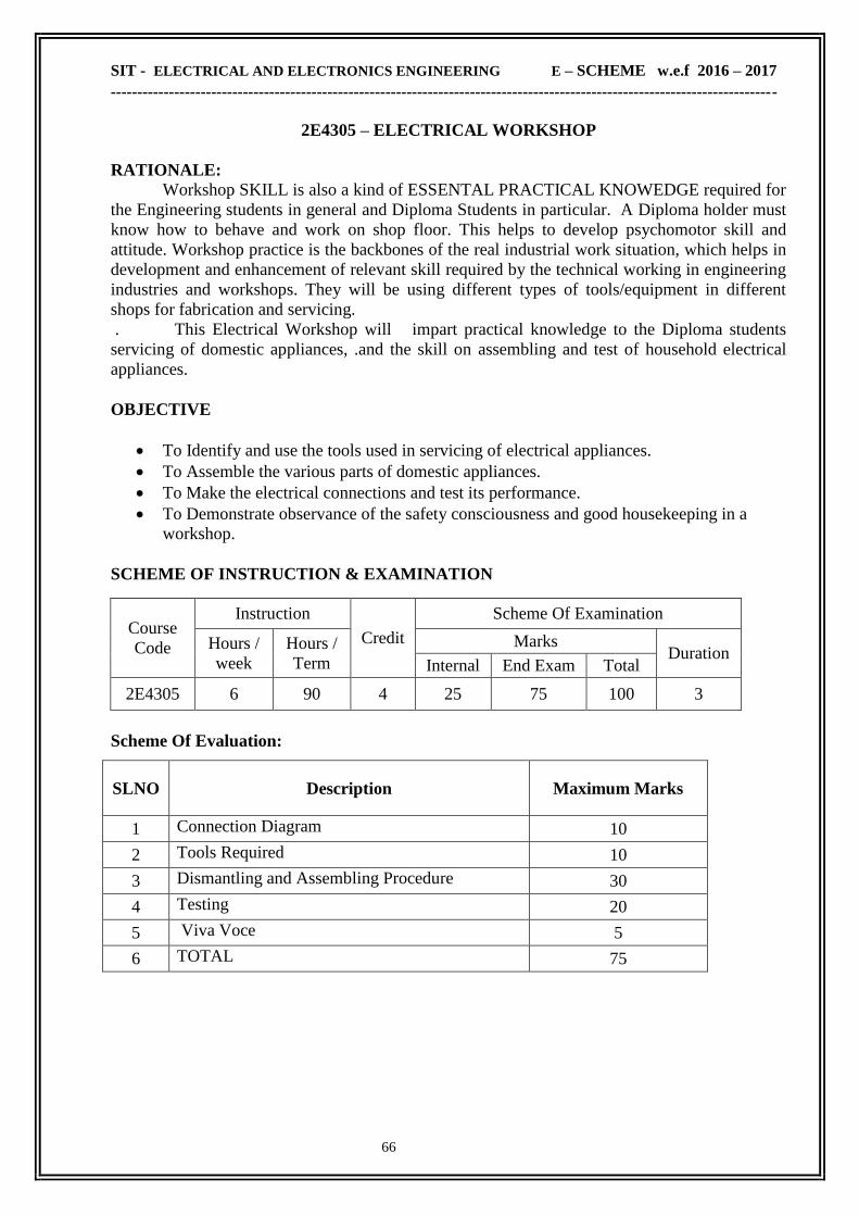
SIT - ELECTRICAL AND ELECTRONICS ENGINEERING E – SCHEME w.e.f 2016 – 2017
------------------------------------------------------------------------------------------------------------------------------
66
2E4305 – ELECTRICAL WORKSHOP
RATIONALE:
Workshop SKILL is also a kind of ESSENTAL PRACTICAL KNOWEDGE required for
the Engineering students in general and Diploma Students in particular. A Diploma holder must
know how to behave and work on shop floor. This helps to develop psychomotor skill and
attitude. Workshop practice is the backbones of the real industrial work situation, which helps in
development and enhancement of relevant skill required by the technical working in engineering
industries and workshops. They will be using different types of tools/equipment in different
shops for fabrication and servicing.
. This Electrical Workshop will impart practical knowledge to the Diploma students
servicing of domestic appliances, .and the skill on assembling and test of household electrical
appliances.
OBJECTIVE
To Identify and use the tools used in servicing of electrical appliances.
To Assemble the various parts of domestic appliances.
To Make the electrical connections and test its performance.
To Demonstrate observance of the safety consciousness and good housekeeping in a
workshop.
SCHEME OF INSTRUCTION & EXAMINATION
Course
Code
Instruction
Credit
Scheme Of Examination
Hours /
week
Hours /
Term
Marks Duration
Internal End Exam Total
2E4305 6 90 4 25 75 100 3
Scheme Of Evaluation:
SLNO Description Maximum Marks
1 Connection Diagram 10
2 Tools Required 10
3 Dismantling and Assembling Procedure 30
4 Testing 20
5 Viva Voce 5
6 TOTAL 75

SIT - ELECTRICAL AND ELECTRONICS ENGINEERING E – SCHEME w.e.f 2016 – 2017
------------------------------------------------------------------------------------------------------------------------------
67
2E4305 – ELECTRICAL WORKSHOP
CONTENT DETAILS
SLNO List of Exercises
1 Familiarization of tools used for electrical repair works and personal
protection equipments.
2 Dismantling of Electrical iron box, identifying the parts, checking the
conditions, assembling and testing.
3 Dismantling of Mixer Grinder, identifying the parts, checking the
conditions, assembling and testing.
4 Dismantling of Wet Grinder, identifying the parts, checking the conditions,
assembling and testing.
5 Assembling the accessories of ceiling fan, test the connections of winding
& capacitor and run the fan with speed regulator.
6 Connect the battery and inverter to supply partial load in a domestic wiring
during mains failure.
7. Assembling and testing of 15 watts LED light.
8. Battery charging through solar panel. Connect solar panel to charge
battery through charge controller.
9. Dismantling of induction heater, identifying the parts, checking the
conditions, assembling and testing
10. Dismantling of Washing Machine, identifying the parts, checking the
conditions, assembling and testing.
Equipment / Materials required: SLNO DESCRIPTION QUANTITY
1 Tools 2 sets
2. Protective Devices 2 sets
3. Electric Iron Box 2
4 Mixer Grinder 2
5. Wet Grinder 2
6. Ceiling Fan 2
7. Inverter 2
8. LED lamp with fitting 5
9. Battery Charger 1
10. Induction heater 1
11 Washing Machine 1

SIT - ELECTRICAL AND ELECTRONICS ENGINEERING E – SCHEME w.e.f 2016 – 2017
------------------------------------------------------------------------------------------------------------------------------
68
COURSE OUTCOME
CO1 Able to identify and use the tools used in servicing of electrical appliances.
CO2 Able to assemble the various parts of domestic appliances.
CO3 Able to make the electrical connections and test its performance.
CO4 Demonstrate observance of the safety consciousness and good housekeeping in a
workshop.
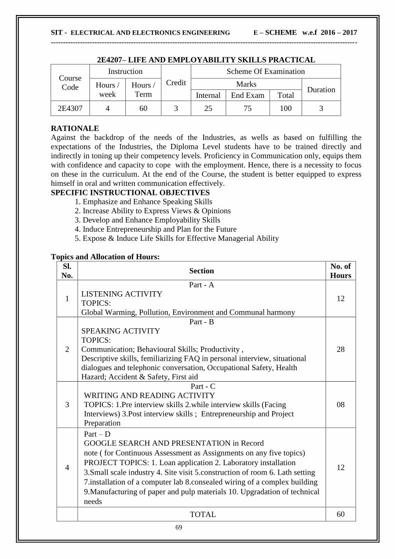
SIT - ELECTRICAL AND ELECTRONICS ENGINEERING E – SCHEME w.e.f 2016 – 2017
------------------------------------------------------------------------------------------------------------------------------
69
2E4207– LIFE AND EMPLOYABILITY SKILLS PRACTICAL
Course
Code
Instruction
Credit
Scheme Of Examination
Hours /
week
Hours /
Term
Marks Duration
Internal End Exam Total
2E4307 4 60 3 25 75 100 3
RATIONALE
Against the backdrop of the needs of the Industries, as wells as based on fulfilling the
expectations of the Industries, the Diploma Level students have to be trained directly and
indirectly in toning up their competency levels. Proficiency in Communication only, equips them
with confidence and capacity to cope with the employment. Hence, there is a necessity to focus
on these in the curriculum. At the end of the Course, the student is better equipped to express
himself in oral and written communication effectively.
SPECIFIC INSTRUCTIONAL OBJECTIVES
1. Emphasize and Enhance Speaking Skills
2. Increase Ability to Express Views & Opinions
3. Develop and Enhance Employability Skills
4. Induce Entrepreneurship and Plan for the Future
5. Expose & Induce Life Skills for Effective Managerial Ability
Topics and Allocation of Hours:
Sl.
No. Section
No. of
Hours
1
Part - A
LISTENING ACTIVITY
TOPICS:
Global Warming, Pollution, Environment and Communal harmony
12
2
Part - B
SPEAKING ACTIVITY
TOPICS:
Communication; Behavioural Skills; Productivity ,
Descriptive skills, femiliarizing FAQ in personal interview, situational
dialogues and telephonic conversation, Occupational Safety, Health
Hazard; Accident & Safety, First aid
28
3
Part - C
WRITING AND READING ACTIVITY
TOPICS: 1.Pre interview skills 2.while interview skills (Facing
Interviews) 3.Post interview skills ; Entrepreneurship and Project
Preparation
08
4
Part – D
GOOGLE SEARCH AND PRESENTATION in Record
note ( for Continuous Assessment as Assignments on any five topics)
PROJECT TOPICS: 1. Loan application 2. Laboratory installation
3.Small scale industry 4. Site visit 5.construction of room 6. Lath setting
7.installation of a computer lab 8.consealed wiring of a complex building
9.Manufacturing of paper and pulp materials 10. Upgradation of technical
needs
12
TOTAL 60

SIT - ELECTRICAL AND ELECTRONICS ENGINEERING E – SCHEME w.e.f 2016 – 2017
------------------------------------------------------------------------------------------------------------------------------
70
2E4207– LIFE AND EMPLOYABILITY SKILLS PRACTICAL
CONTENT DETAILS
Sl.
No SECTION
SKILLS TO BE
ACQUIRED ACTIVITY
No,OF
HOURS
1.
PART-A
LISTENING ACTIVITY
TOPICS:
1. Global Warming,
2. Pollution,
3.Environment,Commun
al Harmony
Deductive/reasoning
skills
Cognitive Skills
Retention Skills
Talking down
notes/hints
Answering question
Fill in the blanks the
exact words heard
Brief the read out
passage
04
04
02
02
2.
PART-B
SPEAKING ACTIVITY
TOPICS:
COMMUNICATION:
Behavioural skills;
Productivity,
Occupational safety,
Health Hazards,Accident
&safety,First-
aid,descriptive skillsFAQ
in personal interview
Various situational
dialogues and telephonic
conversation
Personality/psycholo-
gical skills
Pleasing &Amiable
Skills
Assertive skills
Expressive skills
Fluency/compatibility
skills
Leadership/team
Spirit skills
Interview
skills(FAQ)
Instant sentence
making
Say
expression/phrases
Self introduction/
another higher official
in company
Describe/explain
products
Dialogues on technical
ground discuss
&interact Group
Discussion
02
02
04
06
06
08
3.
PART-C
READING AND
WRITING ACTIVITY
TOPICS:
Facing interviews;
entrepreneurship and
Project Preparation
Creative &
Reasoning Skills
Creative
&Composing
Skills
Attitude& Aim Skills
Entrepreneurship
Skills
Frame New words
with the given
words/Phrases
Prepare an outline of a
project to obtain loan
from bank in
becoming an
entrepreneurship
02
02
02
02
4 PART-D
Google search and
presentation in record
note(for continuous
Assessment on any five
topics)
PROJECT TOPICS:
1. Loan application
2. Laboratory installation
3.Small scale industry
4. Site visit
Cognitive Skills
Presentation Skills
&Interactive Skills
Search in the website
Prepare a presentation
Discuss &Interact
12
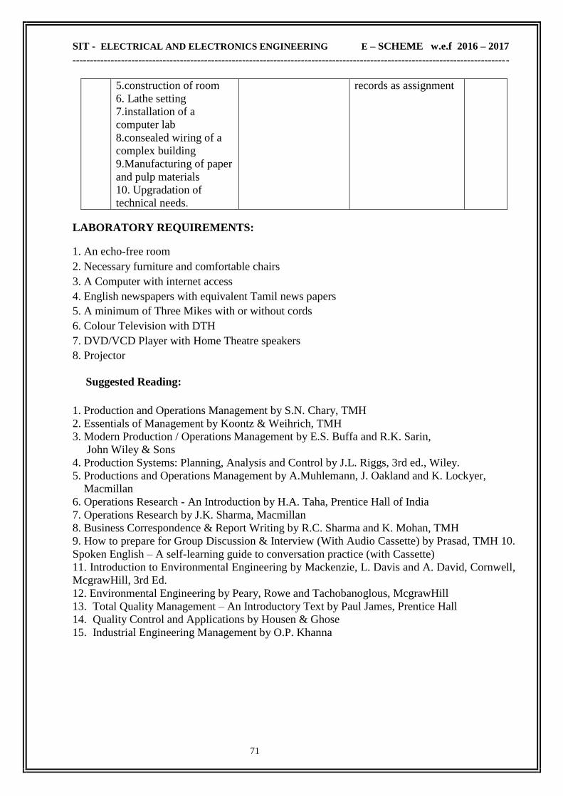
SIT - ELECTRICAL AND ELECTRONICS ENGINEERING E – SCHEME w.e.f 2016 – 2017
------------------------------------------------------------------------------------------------------------------------------
71
5.construction of room
6. Lathe setting
7.installation of a
computer lab
8.consealed wiring of a
complex building
9.Manufacturing of paper
and pulp materials
10. Upgradation of
technical needs.
records as assignment
LABORATORY REQUIREMENTS: 1. An echo-free room 2. Necessary furniture and comfortable chairs 3. A Computer with internet access 4. English newspapers with equivalent Tamil news papers 5. A minimum of Three Mikes with or without cords 6. Colour Television with DTH 7. DVD/VCD Player with Home Theatre speakers 8. Projector
Suggested Reading:
1. Production and Operations Management by S.N. Chary, TMH
2. Essentials of Management by Koontz & Weihrich, TMH
3. Modern Production / Operations Management by E.S. Buffa and R.K. Sarin,
John Wiley & Sons
4. Production Systems: Planning, Analysis and Control by J.L. Riggs, 3rd ed., Wiley.
5. Productions and Operations Management by A.Muhlemann, J. Oakland and K. Lockyer,
Macmillan
6. Operations Research - An Introduction by H.A. Taha, Prentice Hall of India
7. Operations Research by J.K. Sharma, Macmillan
8. Business Correspondence & Report Writing by R.C. Sharma and K. Mohan, TMH
9. How to prepare for Group Discussion & Interview (With Audio Cassette) by Prasad, TMH 10.
Spoken English – A self-learning guide to conversation practice (with Cassette)
11. Introduction to Environmental Engineering by Mackenzie, L. Davis and A. David, Cornwell,
McgrawHill, 3rd Ed.
12. Environmental Engineering by Peary, Rowe and Tachobanoglous, McgrawHill
13. Total Quality Management – An Introductory Text by Paul James, Prentice Hall
14. Quality Control and Applications by Housen & Ghose
15. Industrial Engineering Management by O.P. Khanna
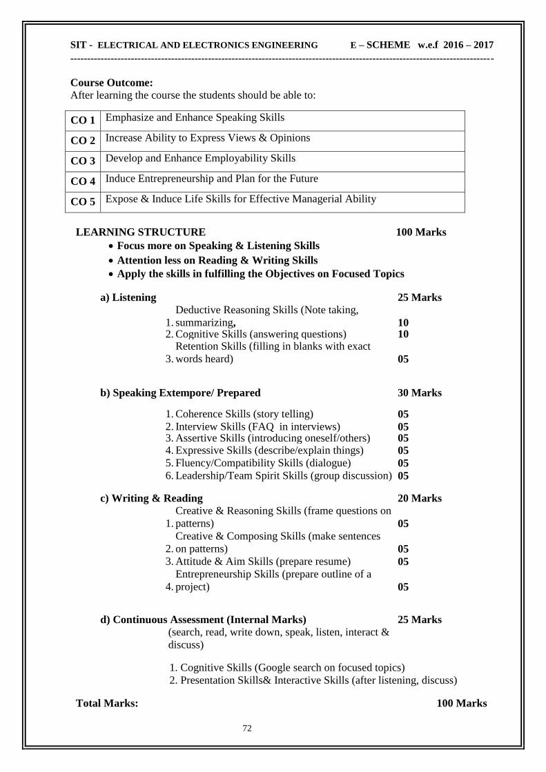
SIT - ELECTRICAL AND ELECTRONICS ENGINEERING E – SCHEME w.e.f 2016 – 2017
------------------------------------------------------------------------------------------------------------------------------
72
Course Outcome:
After learning the course the students should be able to:
CO 1 Emphasize and Enhance Speaking Skills
CO 2 Increase Ability to Express Views & Opinions
CO 3 Develop and Enhance Employability Skills
CO 4 Induce Entrepreneurship and Plan for the Future
CO 5 Expose & Induce Life Skills for Effective Managerial Ability
LEARNING STRUCTURE 100 Marks
Focus more on Speaking & Listening Skills Attention less on Reading & Writing Skills
Apply the skills in fulfilling the Objectives on Focused Topics
a) Listening 25 Marks
1.
Deductive Reasoning Skills (Note taking,
summarizing, 10 2. Cognitive Skills (answering questions) 10
3.
Retention Skills (filling in blanks with exact
words heard) 05
b) Speaking Extempore/ Prepared 30 Marks
1. Coherence Skills (story telling) 05 2. Interview Skills (FAQ in interviews) 05 3. Assertive Skills (introducing oneself/others) 05 4. Expressive Skills (describe/explain things) 05 5. Fluency/Compatibility Skills (dialogue) 05 6. Leadership/Team Spirit Skills (group discussion) 05
c) Writing & Reading 20 Marks
1.
Creative & Reasoning Skills (frame questions on
patterns) 05
2.
Creative & Composing Skills (make sentences
on patterns) 05 3. Attitude & Aim Skills (prepare resume) 05
4.
Entrepreneurship Skills (prepare outline of a
project) 05
d) Continuous Assessment (Internal Marks) 25 Marks (search, read, write down, speak, listen, interact &
discuss) 1. Cognitive Skills (Google search on focused topics)
2. Presentation Skills& Interactive Skills (after listening, discuss) Total Marks: 100 Marks

SIT - ELECTRICAL AND ELECTRONICS ENGINEERING E – SCHEME w.e.f 2016 – 2017
------------------------------------------------------------------------------------------------------------------------------
73
Continuous Assessment (Internal Marks)
I LISTENING (3 exercises), SPEAKING (6 exercises) and 10 Marks READING & WRITING (4 exercises).
All activities shall be recorded in the Record note.
13 exercises x 10 marks = 130 marks. Reduced to 10 marks
II Present in the Record Note on any 5 topics prescribed in syllabus as Assignments 10 Marks
Topics
5 Assignments x 10 Marks = 50 marks. Average of 5 Assignments
is 10 marks
III Attendance 5 Marks
Total 25 Marks

SIT - ELECTRICAL AND ELECTRONICS ENGINEERING E – SCHEME w.e.f 2016 – 2017
------------------------------------------------------------------------------------------------------------------------------
74
TERM - V

SIT - ELECTRICAL AND ELECTRONICS ENGINEERING E – SCHEME w.e.f 2016 – 2017
------------------------------------------------------------------------------------------------------------------------------
75
2E5306 - POWER SYSTEM –I
RATIONALE
Power system comprises generation, transmission and distribution. In this course generation,
transmission and distribution, types of generation schemes , transmission with transmission loss
and efficiencies , different type of sub-stations , different type of distribution schemes, EHV AC
and HVDC transmission, underground cable and economics aspects involved are dealt with.
Further types of tariff are briefly included to give brief and overall idea to the technicians.
In power stations and sub stations applications of switchgear and various protective schemes
applied to various electrical equipment/ machines/ bus bars, feeders, transmission lines/
distribution lines etc. are essential to minimize normal and abnormal faults and for safety of
human being. Safety is the major criteria of every power station and substation for machines/
equipment and human beings. Operating skill of switchgear and protective systems is much
essential for the technician working in the particular work area.
Essential efforts are being made in this course to ensure that students develop skills in operating
various controls and switchgear in power system. He/she needs to make remedial measures for
faults/abnormalities in machines/equipment in power system using appropriate diagnostic
instrument/devices.
OBJECTIVES
To understand Conventional Power Plants - layout, site.
Non conventional power generation - methods.
Grid system.
Energy Conservation, Audit and Management
AC transmission -supports, conductors, lines, effects.
High Voltage DC transmission.
Line insulators, UG cables.
Fuse-types and their characteristics.
Principle, types and location of current limiting reactors.
Causes of over voltages & Methods of reducing over voltages.
Operating principles, construction & applications of lightening arrestor.
Insulation co-ordination & volt- time characteristic.
Importance of Neutral Earthing, Methods, advantages & applications.
Necessity & types of interruption devices like ACB, OCB, ABCB, SF6 and vacuum circuit
breakers.
Working principle and various types of circuit breakers
Concept of protective relay and its selection.
Classification of relays.
Principle of working and operation of relays and their construction.
Basic terms related to relay like pick up value, reset value- and operating current etc.

SIT - ELECTRICAL AND ELECTRONICS ENGINEERING E – SCHEME w.e.f 2016 – 2017
------------------------------------------------------------------------------------------------------------------------------
76
Use the static relays in modern power system.
Settings of various types of relays.
Maintenance and testing of relays.
SCHEME OF INSTRUCTION & EXAMINATION
Course
Code
Instruction
Credit
Scheme Of Examination
Hours /
week
Hours /
Term
Marks Duration
Internal End Exam Total
2E5306 5 75 5 25 75 100 3
TOPICS AND ALLOCATION OF HOURS & MARKS :
Unit No Name of the Topic Hours Marks
I Generation Of Electrical Power 13 15
II A.C Transmission And HVDC Transmission 13 15
III Line Insulators And Underground Cables 13 15
IV Circuit Breakers And Over Voltage Protection 12 15
V Protective Relays And Grounding 12 15
Revision 05
Cycle Tests and Model Examination 07
Total
75 75

SIT - ELECTRICAL AND ELECTRONICS ENGINEERING E – SCHEME w.e.f 2016 – 2017
------------------------------------------------------------------------------------------------------------------------------
77
2E5306 - POWER SYSTEM –I
CONTENT DETAILS
UNIT I : GENERATION OF ELECTRICAL POWER
1.1 Conventional methods of Generation : Introduction-Conventional methods of power
generation -schematic arrangement and choice of site for Hydel, thermal, Nuclear power
plants-Advantages and Disadvantages - Comparison of these power plants - Principle and
types of co generation
1.2 Economics of power Generation : Grid or Inter connected system - Advantages of
Inter connected systems- Load Transfer through Inter connector - Load curves and
Load duration curves - connected load - Average load -Maximum Demand -Demand factor -
Load factor - Plant Use Factor - Diversity factor - Plant capacity factor -Significance of high
load & diversity factors - Load sharing between base load and peak load plants - Load
Despatching centre -Functions - stand alone system
1.3 Tariff : Factors influencing tariff – Types of tariff – Flat rate tariff – Two part tariff –
Maximum demand tariff – Three part tariff – Block rate tariff – Power factor tariff – Simple
problems
UNIT II : A.C TRANSMISSION AND HVDC TRANSMISSION
2.1 A.C. Transmission,conductors & Line supports : Introduction-Typical Layout of A.C.
Power supply scheme various system of power Transmission-Advantages and Disadvantages
of A.C Transmission- High Transmission Voltage-Advantages-Economic choice of
Transmission voltage-Elements of a Transmission Line - Economic choice of conductor size-
Kelvin's Law- Its limitation-over Head Line-Conductor materials and their properties-Line
supports-Its properties - Types of supports and their applications-spacing between
conductors-length of span
2.2 Calculations in overhead lines : Sag in over head lines-Calculation of Sag- When the
supports are at equal and unequal levels – Problems - constants of a Transmission line-
Transposition of Transmission lines-Skin Effect- Ferranti Effect-Corona- formation and
corona loss-Factors affecting corona- Advantages and Disadvantages-Classification of O.H.
Transmission lines- performance of single phase short Transmission line - voltage regulation
and Transmission Efficiency- Problems.
2.3 H.V.D.C Transmission: Advantages and Disadvantages of D.C Transmission- Layout
Scheme and principle of High Voltage D.C Transmission - D.C link configurations
(monopolar, Bipolar and Homopolar)-HVDC convertor Station(Schematic diagram only)-
Comparision between constant current and constant voltage HVDC systems.
UNIT III : LINE INSULATORS AND UNDERGROUND CABLES
3.1 Line Insulators: Introduction-Line Insulator materials-Properties of Insulators-
Types- causes of failure of Insulators-Testing of Insulators-Potential Distribution over
suspension Insulator string-String Efficiency - methods of improving string Efficiency-
problems.
3.2 Underground cables: Introduction-Advantages and requirement of cables- construction-
of a three core cable-Insulating materials for cables- properties of Insulating materials used in
cables- classification of cables-cables for three phase service- construction of Belted cable,
screened cable, Pressure cables
3.3 Laying, Grading & Fault finding in cables : Laying of underground cables-Direct laying,
Draw- in- system, solid system- Advantages and Disadvantages- Grading of cables-
capacitance grading, Inter sheath grading (No derivation and Problems)

SIT - ELECTRICAL AND ELECTRONICS ENGINEERING E – SCHEME w.e.f 2016 – 2017
------------------------------------------------------------------------------------------------------------------------------
78
UNIT IV : CIRCUIT BREAKERS AND OVER VOLTAGE PROTECTION
4.1 Circuit Breakers: Switch gear-Essential features of Switch gear-faults in a Power system
(definition only). Basic principle of circuit Breaker -Arc Phenomenon- methods of Arc
extinction-Arc voltage -Restriking voltage and recovery voltage-Rate of rise of restriking
voltage- current chopping Interruption of capacitive current -resistance switching-C.B
ratings - Breaking capacity, making capacity, short time rating - Auto reclosing in circuit
Breakers - Classification of C.B.S - construction, working principle , merits and Demerits of Air
Blast C.B, SF6 and vacuum C.B-Maintenance schedule for circuit breakers. D.C breaking -
Problems of D.C breaking-Schematic for HVDC C.B- producing current zero.
4.2 Fuses: Desirable characteristics-Fuse Element materials-current rating of fuse elements-
fusing current-Cut off current-L.V fuses-Rewirable fuse, HRC cartridge fuse,HRC fuse with
tripping device -H.V. fuses-cartridge type, liquid type and metal clad-fuses-Comparision of fuse
and circuit breaker.
4.3 Over voltage protection: Voltage surge- causes of over voltage-Lightning-Types of
lightning strokes -Direct stroke, Indirect stroke-Harmful Effects of lightning - Protection
against lightning-Earthing screen, Overhead ground wires, Lightning arresters- Expulsion
type, Gapless arrester.
UNIT V : PROTECTIVE RELAYS AND GROUNDING
5.1 Protective relays: Basic principled -Fundamental requirements of protective
relaying-Primary and back up Protection-relay characteristics-relay timing -Instantaneous
relay –Inverse time relay and Definite time lag relay-Inverse definite minimum time relay-
classification of relays-Construction, Principle of operation and applications of Induction type
over current relay Directional and Non-directional), Distance relay, Differential relay
5.2 Modern relays : Negative sequence relay, Induction type reverse power relay, Earth
leakage relay. Static relays- Basic elements of static relay -Schematic diagram and operating
principle of smart protective relays - current, Impedance, directional, reactance and Mho relays.
5.3 Grounding: Introduction - Equipment grounding - system grounding - ungrounded
Neutral system - Necessity of Neutral grounding -methods - solid grounding, Resistance
grounding - Reactance grounding, Resonant grounding - Earthing Transformer.
TEXT BOOK
Sl.No. Title Author Publisher
1 Principles of Power Systems
3rd re-edition, 2005 VK. Mehta
S.Chand & Co New
Delhi .
REFERENCE BOOKS
Sl.No. Title Author Publisher
1 A Course in Electrical Power
2013 Edition, 2013
Soni , Gupta &
Bhatnagar
Dhanpath Rai & Co (P)
Ltd., New Delhi
2 Electrical Power System
Re print-2009 S.L. Uppal
Khanna Publishers, New
Delhi
3 A Course in Electrical Power
2013 Edition, 2013 J.P. Gupta
Katson Publishing
House, New Delhi

SIT - ELECTRICAL AND ELECTRONICS ENGINEERING E – SCHEME w.e.f 2016 – 2017
------------------------------------------------------------------------------------------------------------------------------
79
ONLINE RESOURCES
www.nptel.ac.in/courses/108102047/
www.electrical4u.com/protection-system-in-power-system/
www.electrical4u.com/electrical-switchgear-protection/
www.electrical4u.com/electrical-power-transmission-system-and-network/
COURSE OUTCOME
CO1
Able to understand Conventional Power Plants - layout, site.
Able to understand Non conventional power generation - methods.
Able to understand Grid system, Energy Conservation, Audit and Management
CO2 Able to understand AC transmission -supports, conductors, lines, effects.
Able to understand High Voltage DC transmission, Line insulators, UG cables.
CO3
Able to know Fuse-types and their characteristics.
Able to know Principle, types and location of current limiting reactors.
Able to know Causes of over voltages & Methods of reducing over voltages.
CO4
Able to know Insulation co-ordination & volt- time characteristic.
Able to know the Importance of Neutral Earthing, Methods, advantages &
applications.
Able to know the Necessity & types of interruption devices like ACB, OCB, ABCB,
SF6 and vacuum circuit breakers.
CO5
Able to understand Working principle and various types of circuit breakers
Able to know the Concept of protective relay and its selection.
Having the knowledge about Classification of relays, Principle of working and
operation of relays and their construction.
Knowledge about Basic terms related to relay like pick up value, reset value- and
operating current etc. ,Use the static relays in modern power system, Settings of
various types of relays, Maintenance and testing of relays.
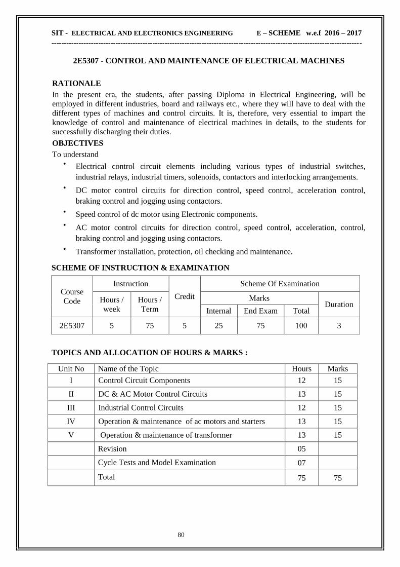
SIT - ELECTRICAL AND ELECTRONICS ENGINEERING E – SCHEME w.e.f 2016 – 2017
------------------------------------------------------------------------------------------------------------------------------
80
2E5307 - CONTROL AND MAINTENANCE OF ELECTRICAL MACHINES
RATIONALE
In the present era, the students, after passing Diploma in Electrical Engineering, will be
employed in different industries, board and railways etc., where they will have to deal with the
different types of machines and control circuits. It is, therefore, very essential to impart the
knowledge of control and maintenance of electrical machines in details, to the students for
successfully discharging their duties.
OBJECTIVES
To understand Electrical control circuit elements including various types of industrial switches,
industrial relays, industrial timers, solenoids, contactors and interlocking arrangements.
DC motor control circuits for direction control, speed control, acceleration control,
braking control and jogging using contactors.
Speed control of dc motor using Electronic components.
AC motor control circuits for direction control, speed control, acceleration, control,
braking control and jogging using contactors.
Transformer installation, protection, oil checking and maintenance.
SCHEME OF INSTRUCTION & EXAMINATION
Course
Code
Instruction
Credit
Scheme Of Examination
Hours /
week
Hours /
Term
Marks Duration
Internal End Exam Total
2E5307 5 75 5 25 75 100 3
TOPICS AND ALLOCATION OF HOURS & MARKS :
Unit No Name of the Topic Hours Marks
I Control Circuit Components 12 15
II DC & AC Motor Control Circuits 13 15
III Industrial Control Circuits 12 15
IV Operation & maintenance of ac motors and starters 13 15
V Operation & maintenance of transformer 13 15
Revision 05
Cycle Tests and Model Examination 07
Total 75 75

SIT - ELECTRICAL AND ELECTRONICS ENGINEERING E – SCHEME w.e.f 2016 – 2017
------------------------------------------------------------------------------------------------------------------------------
81
2E5307 - CONTROL AND MAINTENANCE OF ELECTRICAL MACHINES
CONTENT DETAILS
UNIT I : CONTROL CIRCUIT COMPONENTS
Switches : - Push button, selector, drum, limit, pressure, temperature (Thermostat), float,
zero speed and Proximity switches.
Relays -Voltage relay, dc series current relay, frequency response relay, latching relay and phase
failure relay (single phasing preventer). Over current relay -Bimetallic thermal over load relay
and Magnetic dash pot oil filled relay.
Timer -Thermal, Pneumatic and Electronic Timer. Solenoid Valve, Solenoid type contactor
(Air Break Contactor), Solid State Relay, Simple ON-OFF motor control circuit, Remote
control operation and interlocking of drives.
UNIT II : DC & AC MOTOR CONTROL CIRCUITS
DC Motor Control Circuits : Current limit acceleration starters -Series relay and counter EMF
starters - Definite Time acceleration starters.
AC Motor Control Circuits : Motor current at start and during acceleration – No load speed
and final speed of motor -DOL starter – Automatic auto transformer starter (open circuit and
closed circuit transition) - Star/Delta starter (semi automatic and automatic)– Starter for
two speed, two winding motor –Reversing the direction of rotation of induction motor –Plug
stopping of the motor -Dynamic braking -Three step rotor resistance starter for wound
induction motor - Secondary frequency acceleration starter
UNIT III : INDUSTRIAL CONTROL CIRCUITS
Planner machine — Contactor control circuit — Logic control circuit-- Skip hoist control
Automatic control of a water pump — Control of electric oven — Control of air
compressor - Control of over head crane — Control of conveyor system — Control of
elevator — Trouble spots in control circuits — General procedure for trouble shooting.
UNIT IV : OPERATION & MAINTENANCE OF AC MOTORS AND STARTERS
Change the direction of Rotation, Role of Single phase preventer, Types of enclosures,
Permissible overload, effect of ambient temperature, Insulation classification, Indicating &
Protecting devices for Large Size Motors, If overload mechanism trips frequently what action to
be taken, Control devices for motors, role of relays in motor, Points to be attended during
periodical maintenance, Air gap measurement, Ball & Roller bearing usage, precautions in fitting
bearings, bearing problems, Alignment of directly coupled motors, Static and Dynamic balancing
of rotor, Causes of low insulation resistance, rectification of low insulation resistance problem,
drying out of motors, Step to be taken if a motor is unduly hot, Vacuum impregnation, Selection
of starters for High/Low starting torque applications.
UNIT V : OPERATION & MAINTENANCE OF TRANSFORMER
Forces generated in transformer during short circuit - Noise in operation – Reason for
temperature rise- -insulation resistance-Drying out- precaution for paralleling transformer-inrush
current and remedy- insulation co-ordination-effect on insulation during star point earthing –
transformer maintenance schedule – action to be taken while transformer oil, temperature rises
unduly – points to be checked by oil level tends to fall down – attention required for bushing and
insulator

SIT - ELECTRICAL AND ELECTRONICS ENGINEERING E – SCHEME w.e.f 2016 – 2017
------------------------------------------------------------------------------------------------------------------------------
82
TEXT BOOK
Sl.No. Title Author Publisher
1 Control of Electrical Machines
1st Edition 2006 S.K. Bhattacharya
New Age International
Publishers ,New Delhi.
REFERENCE BOOKS
Sl.No. Title Author Publisher
1
Automation, Production System
And Computer-Integrated
Manufacturing 1st Edition 2016
Mikell P. Groover Prentice Hall of India (P)
Ltd., New Delhi
2 Control of Electrical Machines
1st Edition 1973 Irving L Kosow
Prentice Hall of India (P)
Ltd., New Delhi
3 Electronic motor control
10th Edition 2014 Walter Alrich
Tarapoewala
publications,MUMBAI
ONLINE RESOURCES
electrical-engineering-portal.com/download-center/books-and-guides/
www.electronics.wisc-online.com/category.aspx
COURSE OUTCOME
CO1
Able to understand Electrical control circuit elements including various types of
industrial switches, industrial relays, industrial timers, solenoids, contactors and
interlocking arrangements.
CO2 Able to understand DC motor control circuits for direction control, speed control,
acceleration control, braking control and jogging using contactors.
CO3 Able to understand Speed control of dc motor using Electronic components.
CO4 Able to understand AC motor control circuits for direction control, speed control,
acceleration, control, braking control and jogging using contactors.
CO5 Able to understand Transformer installation, protection, oil checking and maintenance.

SIT - ELECTRICAL AND ELECTRONICS ENGINEERING E – SCHEME w.e.f 2016 – 2017
------------------------------------------------------------------------------------------------------------------------------
83
2E5403.1 - MICRO CONTROLLER
RATIONALE
Microcontrollers have also assumed great significance in the field of electronics and common
goods industry, and thus considered to be an important field of engineering. This course aims
to expose the students to both of these and give them adequate knowledge of these topics.
OBJECTIVES
On completion of the following units of syllabus contents, the students must be able to Understand the history and need of Microprocessor.
Understand the internal architecture details of 8085 Microprocessor.
Explain Architecture of 8051 Microcontroller & the functions of various registers.
Understand interrupt structure of 8051.
Understand serial data communication concepts.
Understand the programming techniques.
Explain various addressing modes & Write simple programs using 8051.
Understand the block diagram and control word formats for peripheral devices.
Understand how to interface with RS232C.
Understand how to interface with 8255.
Understand various application of 8051 Microcontroller
SCHEME OF INSTRUCTION & EXAMINATION
Course
Code
Instruction
Credit
Scheme Of Examination
Hours /
week
Hours /
Term
Marks Duration
Internal End Exam Total
2E5403.1 5 75 5 25 75 100 3
TOPICS AND ALLOCATION OF HOURS & MARKS :
Unit No Name of the Topic Hours Marks
I Architecture of 8051 & their Pin details 13 15
II Overview of 8051 Instruction Sets 13 15
III Interrupts and Programming Examples 13 15
IV Timer/Counter and Serial Communication: 12 15
V Interfacing Techniques 12 15
Revision 05
Cycle Tests and Model Examination 07
Total 75 75

SIT - ELECTRICAL AND ELECTRONICS ENGINEERING E – SCHEME w.e.f 2016 – 2017
------------------------------------------------------------------------------------------------------------------------------
84
2E5403.1 - MICRO CONTROLLER
CONTENT DETAILS
UNIT I : ARCHITECTURE OF 8051 & THEIR PIN DETAILS
1.1 Introduction to microprocessor & microcontroller : Architecture of 8085 -Functions
of each block. Comparison of Microprocessor and Microcontroller -Features of microcontroller -
Advantages of microcontroller -Applications Of microcontroller -Manufactures of
microcontroller.
1.2 Architecture of 8051 : Block diagram of Microcontroller –Functions of each block. Pin
details of 8051 -Oscillator and Clock -Clock Cycle -State - Machine Cycle -Instruction cycle –
Reset - Power on Reset - Special function registers : Program Counter -PSW register -Stack -
I/O Ports .
1.3 Memory Organisation: ROM - RAM - Memory Organization of 8051,Interfacing
external memory to 8051
UNIT II : OVERVIEW OF 8051 INSTRUCTION SETS:
2.1 Assembler and Addressing Modes : Instruction Format, Different addressing modes of
8051, Assembling and running an 8051 program –Structure of Assembly Language -Assembler
directives.
2.2 Instruction Sets : Classification of 8051 Instructions(based on Length) -Classification
of 8051 Instructions(based on Function) .Data Handling instructions - Data transfer
instructions - Arithmetic Instructions - Format of these instructions and examples
2.3 Logical Instructions & control instructions: Logical instructions(byte Operands) ,
Branching instructions – unconditional & conditional jump instructions - Format of these
instructions and examples
UNIT III : I/O , INTERRUPTS AND PROGRAMMING EXAMPLES:
3.1 I/O : Bit addresses for I/O and RAM - I/O programming - I/O bit manipulation
programming - Bit Manipulation Instructions
3.2 Interrupts & Interrupt handling - Interrupts available in 8051,their vector addresses,
Interrupt priority in 8051- Interrupt related SFRs: interrupt enable register (IE) Interrupt
priority register (IP), Interrupt handling - Programming Timer Interrupts –Programming
external hardware interrupts -Programming the serial communication interrupt ( Basic Level)
3.3 Programs : Multibyte Addition - 8 Bit Multiplication and Division - Biggest Number /
Smallest Number -Ascending order / Descending order –Conversion Programs -HEX to BCD,
BCD to HEX , HEX to ASCII & ASCII to Binary -Time delay routines
UNIT IV : TIMER/COUNTER AND SERIAL COMMUNICATION:
4.1 Special function registers : SFRs used for Timer/Counter -Timer 0 and Timer 1 registers -
TCON register – TMOD register - SFRs used for Serial Communication - SCON register -
SBUF register - PCON register .
4.2 Programming 8051 Timers/ Counter programming : Different modes of Timer -
Programming Modes - Mode 0,Mode 1, Mode 2 & Mode 3. Different modes of Counter -
Programming Modes - Mode 0, Mode 1, Mode2 & Mode 3. Simple Programs ( using mode 1 or
mode 2)
4.3 Basics of Serial programming : RS 232 Standards -8051 -connection to RS 232 - 8051
Serial Communication Programming -Programming the 8051 to transfer data serially -
Programming the 8051 to Receive data serially

SIT - ELECTRICAL AND ELECTRONICS ENGINEERING E – SCHEME w.e.f 2016 – 2017
------------------------------------------------------------------------------------------------------------------------------
85
UNIT V : INTERFACING TECHNIQUES
5.1 Programmable interface IC: IC 8255 -Block Diagram -Modes of 8255 -CWR format -
8051 interfacing with the 8255.
5.2 Interfacing circuits : Relays and opto isolators –Sensor interfacing -ADC interfacing -
DAC interfacing -Keyboard interfacing - Seven segment LED Display Interfacing - LCD
display interfacing .
5.3 Microcontroller based Application : Stepper Motor interfacing -DC motor interfacing
PWM.
TEXT BOOK
Sl.No. Title Author Publisher
1
The 8051 microcontroller
And Embedded Systems,
2nd Edition
Muhammad Ali Mazidi
Janice Gillispie Mazidi
Prentice Hall of India
(P) Ltd., New Delhi
REFERENCE BOOKS
Sl.No. Title Author Publisher
1
8051 microcontroller Architecture,
Programming & Applications
2nd Edition 1996
Kenneth J. Ayala Penram International .
2 Using Assembly Language
3rd Edition 1992 Allen L.Wyatt Sr
Prentice Hall of India
(P) Ltd., New Delhi
ONLINE RESOURCES
www.vssut.ac.in/lecture_notes/lecture1423813120.pdf
www.circuitstoday.com/8051-microcontroller
COURSE OUTCOME
CO1 Able to Understand the internal architecture details of 8085 Microprocessor.
Knowledge about Architecture of 8051 Microcontroller
CO2
Able to Understand the programming techniques.
Able to understand various Addressing modes , write,compile and debug programs
involving decision structures, loops.
CO3 Able to understand interrupt structure of 8051.
CO4 Knowing the concepts of serial communication.
Able to understand how to interface with RS232C.
CO5
Able to understand the block diagram and control word formats for peripheral devices
and understand how to interface with 8255.
Able to understand various application of 8051 Microcontroller

SIT - ELECTRICAL AND ELECTRONICS ENGINEERING E – SCHEME w.e.f 2016 – 2017
------------------------------------------------------------------------------------------------------------------------------
86
2E5403.2 - VLSI DESIGN
RATIONALE:
VLSI stands for "Very Large Scale Integration". This is the field which involves packing
more and more logic devices into smaller and smaller areas. Field programmable gate arrays
(FPGAs) can now contain over a million equivalent logic gates and tens of thousands of flip-
flops. The reality is that today digital systems are designed by writing software in the form of
hardware description languages (HDLs). The most common HDLs used today are VHDL and
Verilog. This subject gives the students the complete idea of VLSI design
OBJECTIVES:
After learning this subject, the students will be able to
Explain the Idea about State Machine Mealy and Moore Machines
Explain the basic idea about Memory Organization
Explain the Architecture of PAL
Explain the Macro cell concept, VHDL design flow
Explain About Various Design Types like Structural , Behavioral and RTL
Explain About Data Flow Description, VHDL packages and Functions
Give schematic diagram introduction to CPLD (Complex Programmable Logic
Device) architecture & FPGA architecture.
Explain the CLB‘s, LUT‘s, DCM units in FPGA.
Explain the XILINX FPGA & CPLD families.
Explain the Hierarchal Design flow, Basic concepts of Verilog HDL
SCHEME OF INSTRUCTION & EXAMINATION
Course
Code
Instruction
Credit
Scheme Of Examination
Hours /
week
Hours /
Term
Marks Duration
Internal End Exam Total
2E5403.2 5 75 5 25 75 100 3
TOPICS AND ALLOCATION OF HOURS & MARKS :
Unit No Name of the Topic Hours Marks
I Combinational Logic Circuits 13 15
II VHDL for combinational logic circuit 13 15
III Sequential Logic circuits 13 15
IV VHDL for sequential Logic circuits 12 15
V PLDS and FPGA circuits 12 15
Revision 05
Cycle Tests and Model Examination 07
Total 75 75

SIT - ELECTRICAL AND ELECTRONICS ENGINEERING E – SCHEME w.e.f 2016 – 2017
------------------------------------------------------------------------------------------------------------------------------
87
2E5403.2 - VLSI DESIGN
CONTENT DETAILS
UNIT I : COMBINATIONAL LOGIC CIRCUITS
1.1 COMBINATIONAL CIRCUIT DESIGN: NMOS and CMOS logic implementation of
Switch, NOT, AND, OR, NAND, and NOR Gates CMOS Transmission Gate. Digital logic
variable, functions, inversion, gate/circuits, Boolean algebra and circuit synthesis using gates
(Up to 4 variables).
1.2 COMBINATIONAL CIRCUIT BUILDING BLOCKS:
Circuit synthesis using Multiplexer, Demultiplexer, Encoders, Decoders, Arithmetic
adder, Subtractor and Comparator circuits. Hazards and races
UNIT II : VHDL FOR COMBINATIONAL LOGIC CIRCUIT
2.1 VHDL FOR COMBINATIONAL CIRCUIT: Introduction to VLSI and its design
process. Introduction to CAD tool and VHDL: Design Entry, Synthesis, and Simulation.
Introduction to HDL and different level of abstractions. Behavioural modeling, dataflow
modeling, structural modeling . HDL Statements and Assignments
2.2 VHDL CODE: AND, OR, NAND, NOR gates, Implementation of Mux, Demux,
Encoder, decoder. Four bit Arithmetic adder, sub tractor and comparator in VHDL
UNIT III : SEQUENTIAL LOGIC CIRCUITS
3.1 SEQUENTIAL CIRCUIT DESIGN: Introduction/Refreshing to Flipflops and its
excitation table, counters and Shift registers
3.2 DESIGN STEPS: State diagram, State table, state assignment. Example for Moore
and Mealy machines. Design of modulo counter (upto 3 bit) with only D flip-flops through
state diagram
UNIT IV : VHDL FOR SEQUENTIAL LOGIC CIRCUITS
4.1 VHDL FOR SEQUENTIAL CIRCUIT: VHDL constructs for storage elements. VHDL
code for D Latch / D, JK and T Flip-flops with or without reset input.
4.2 VHDL EXAMPLES: Counters :Synchronous counters-2 bit &3 bit up counter. 3 bit
up/down counter Decade counter, Johnson Counter
UNIT V : PLDS AND FPGA CIRCUITS
PLDS & FPGA: Introduction to PROM,PLA and PAL. Implementation of combinational
circuits with PROM, PAL and PLA (up to 4 variables).Comparison between PROM, PAL and
PLA. Introduction to Complex Programmable Logic device, Field Programmable Gate Array.
Introduction to ASIC. Types Of ASIC

SIT - ELECTRICAL AND ELECTRONICS ENGINEERING E – SCHEME w.e.f 2016 – 2017
------------------------------------------------------------------------------------------------------------------------------
88
TEXT BOOK
Sl.No. Title Author Publisher
1
Fundamentals of Digital Logic
with VHDL design
2nd
Edition -2008
Stephen brown
Varnesic McGrawHill
REFERENCE BOOKS
Sl.No. Title Author Publisher
1 Digital Design
5th Edition 2013
M.Morris Mono
Michael D.Ciletti Pearson Education.
2 A VHDL Primer
3rd Edition 1999 Bhasker.J Prentice Hall India
ONLINE RESOURCES
www.electrical4u.com/digital-electronics/
www.electronics.wisc-online.com/category.aspx
COURSE OUTCOME
CO1
Able to Understand the fundamentals of different types of MOSFET
Able to the Idea about State Machine Mealy, Moore Machines and Memory
Organization
CO2 Able to explain the Architecture of PAL,explain the Macro cell concept.
Able to describe about the VHDL design flow
CO3
Able to explain about Concurrent Signals,about various design Types like Structural ,
Behavioral and RTL
Able to explain about Data Flow Description
CO4
Knowing the concepts Explain About VHDL packages and Functions
Able to understand schematic diagram of CPLD (Complex Programmable Logic
Device) architecture & FPGA architecture.
Able to explain the CLB‘s, LUT‘s, DCM units in FPGA.
CO5
Able to know the concepts of XILINX FPGA & CPLD families.
Able to understand Hierarchal Design flow.
Able to understand Basic concepts of Verilog HDL
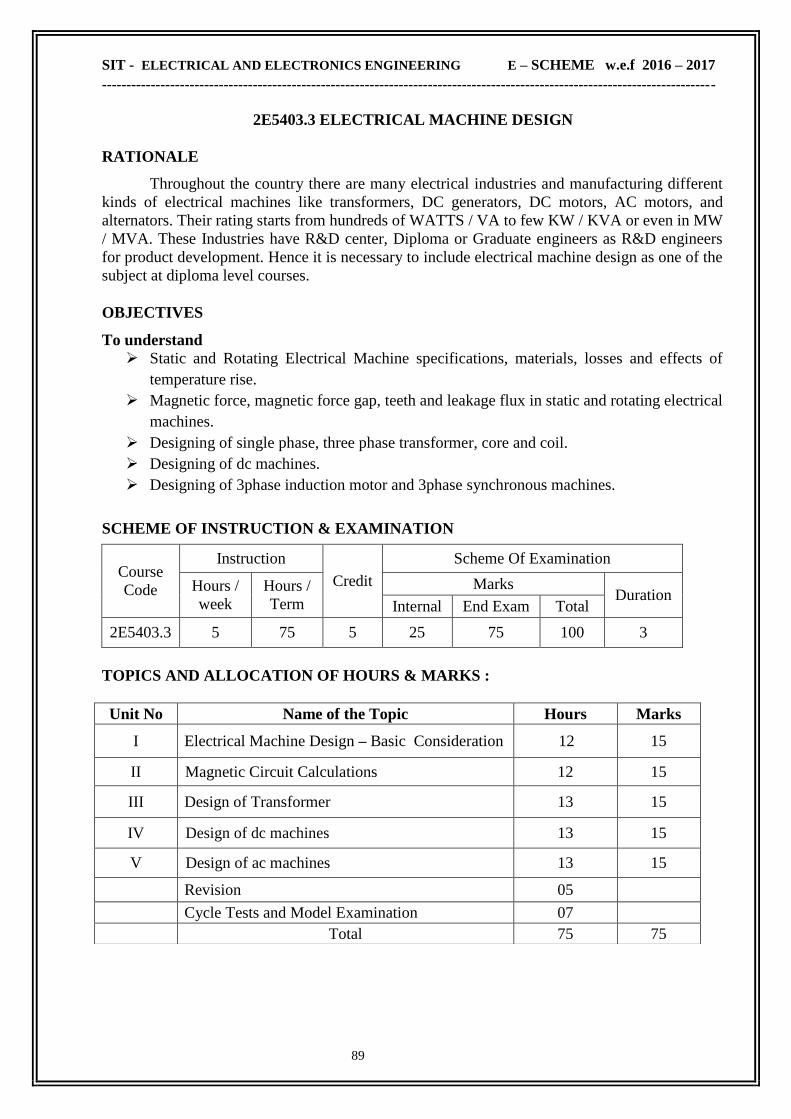
SIT - ELECTRICAL AND ELECTRONICS ENGINEERING E – SCHEME w.e.f 2016 – 2017
------------------------------------------------------------------------------------------------------------------------------
89
2E5403.3 ELECTRICAL MACHINE DESIGN
RATIONALE
Throughout the country there are many electrical industries and manufacturing different
kinds of electrical machines like transformers, DC generators, DC motors, AC motors, and
alternators. Their rating starts from hundreds of WATTS / VA to few KW / KVA or even in MW
/ MVA. These Industries have R&D center, Diploma or Graduate engineers as R&D engineers
for product development. Hence it is necessary to include electrical machine design as one of the
subject at diploma level courses.
OBJECTIVES
To understand
Static and Rotating Electrical Machine specifications, materials, losses and effects of
temperature rise.
Magnetic force, magnetic force gap, teeth and leakage flux in static and rotating electrical
machines.
Designing of single phase, three phase transformer, core and coil.
Designing of dc machines.
Designing of 3phase induction motor and 3phase synchronous machines.
SCHEME OF INSTRUCTION & EXAMINATION
Course
Code
Instruction
Credit
Scheme Of Examination
Hours /
week
Hours /
Term
Marks Duration
Internal End Exam Total
2E5403.3 5 75 5 25 75 100 3
TOPICS AND ALLOCATION OF HOURS & MARKS :
Unit No Name of the Topic Hours Marks
I Electrical Machine Design – Basic Consideration 12 15
II Magnetic Circuit Calculations 12 15
III Design of Transformer 13 15
IV Design of dc machines 13 15
V Design of ac machines 13 15
Revision 05
Cycle Tests and Model Examination 07
Total 75 75

SIT - ELECTRICAL AND ELECTRONICS ENGINEERING E – SCHEME w.e.f 2016 – 2017
------------------------------------------------------------------------------------------------------------------------------
90
2E5403.3 ELECTRICAL MACHINE DESIGN
CONTENT DETAILS
UNIT I : ELECTRICAL MACHINE DESIGN – BASIC CONSIDERATION
1.1 Design Introduction: Design definition – Design consideration – limitation.
1.2 Constructional materials: Constructional elements of Transformers and rotating machines
– constructional materials of electrical machines – conducting magnetic and insulating
materials standard specification.
1.3 General Design & Class of Duty: General design process – main dimensions of rotating
machines – electrical and magnetic losses – temperature – rise – class of duty – limits of
temperature rise.
UNIT II : MAGNETIC CIRCUIT CALCULATIONS
2.1 Magnetic Circuits of Machines: Magnetic circuits of DC machines, round rotation AC
machines, salient poles AC machines and Transformer.
2.2 Magnetic circuit parameters: Specific magnetic and electrical loading – Factor
influencing the specific and magnetic loading –magnetizing curves – calculation of magnetizing
force for the air gap of rotating machines and for teeth.
2.3 Magnetic leakages: Magnetic leakages – leakage flux – leakage reactance – armature slot
leakage reactance
UNIT III : DESIGN OF TRANSFORMER
3.1 Design considerations: Important considerations – core and shell types – distribution
transformers and power transformers – core section – clearance – yoke section – main
dimension.
3.2 Design of Single phase and Three Phase Transformers: Single phase core type
transformers – three phase core type transformer – output coefficient – voltage per turn – specific
magnetic and electric loading of transformer
3.3 Winding design: Winding design – cross over, helix, disc helix.
UNIT IV : DESIGN OF DC MACHINES
4.1 Design considerations: Important design consideration – number of poles – advantages of
large number of poles - air gap.
4.2 Armature and Field System Parameters: Armature slot – current density – field system –
commutator.
4.3 Design of large dc motor: Design of large dc motor – Specific magnetic and electric
loading of dc machines.
UNIT V : DESIGN OF AC MACHINES
5.1 Design Consideration: AC machine design consideration – power equation – separation of
diameter and length – problems.
5.2 Design of Three phase Induction Motor : Three phase induction motor – important design
consideration – standard frames and stampings – gap length – flux density – current density –
power factor – efficiency – slot combination – winding - design of 3 phase induction motors.
5.3 Design of Three phase Synchronous Machines: Three phase synchronous machines –
important design consideration – radial gap length – stator slot – stator coil – rotor construction –
design of 3 phase synchronous machines.

SIT - ELECTRICAL AND ELECTRONICS ENGINEERING E – SCHEME w.e.f 2016 – 2017
------------------------------------------------------------------------------------------------------------------------------
91
TEXT BOOK
Sl.No. Title Author Publisher
1 Principles Of Electrical Machine
Design, 4th Edition 2010 R.K.Agarwal S.K.Kataria & Sons
REFERENCE BOOKS
Sl.No. Title Author Publisher
1
Principles Of Electrical Machine
Design with Computer
2nd Edition 2006
S.K.Sen Oxford & IBH
2 Design of Electrical Machine
5th Edition 2002 Mittle V.N. Standard Book – House
3 Electrical Machine Design
2nd Edition 2000 A. Nagoor kani RBA Publications
4 Performance and Design of AC
Machine 3rd Edition 2005 M.G.Say
CBS Publisher &
Distributor
ONLINE RESOURCES
www.vtu.allsyllabus.com/EEE/sem_6/Electrical_Machine_Design/index.php
COURSE OUTCOME
CO1 Able to understand Static and Rotating Electrical Machine specifications, materials, losses
and effects of temperature rise.
CO2 Able to understand Magnetic force, magnetic force gap, teeth and leakage flux in static
and rotating electrical machines.
CO3 Able to understand Designing of single phase, three phase transformer, core and coil.
CO4 Knowing the concepts of Designing of dc machines.
CO5 Able to understand Designing of 3phase induction motor and 3phase synchronous
machines..

SIT - ELECTRICAL AND ELECTRONICS ENGINEERING E – SCHEME w.e.f 2016 – 2017
------------------------------------------------------------------------------------------------------------------------------
92
2E5308 - CONTROL AND MAINTENANCE OF ELECTRICAL MACHINES LAB
RATIONALE
The purpose of this course is to provide the student with basic skills required to work in the
industry. This course will provides the student a hands-on approach to various types of starters
used for a motor and know the power and control circuit of various starters and braking methods
will be used for AC and DC Motors.
OBJECTIVES
After the completion of this laboratory, the student should be able to Wire and test the control circuit for various types of starters.
Perform breakdown test and acidity test on the given transformer oil.
Wire and test the control circuit for various operations like jogging, reversing control and
braking of Motors.
Conduct test on speed control of DC motor using SCR.
SCHEME OF INSTRUCTION & EXAMINATION
Course
Code
Instruction
Credit
Scheme Of Examination
Hours /
week
Hours /
Term
Marks Duration
Internal End Exam Total
2E5308 6 90 3 25 75 100 3
Scheme Of Evaluation:
SLNO Description Maximum Marks
1 Circuit diagram 20
2 Connection 20
3 Execution 25
4 Result 05
5 Viva Voce 05
6 TOTAL 75

SIT - ELECTRICAL AND ELECTRONICS ENGINEERING E – SCHEME w.e.f 2016 – 2017
------------------------------------------------------------------------------------------------------------------------------
93
2E5308 - CONTROL AND MAINTENANCE OF ELECTRICAL MACHINES LAB
CONTENT DETAILS
SLNO List of Experiments
1 Perform breakdown test and determine the dielectric strength of transformer oil
2 Conduct acidity test on transformer oil.
3 Test the timing characteristic of thermal over load relay
4 Remote and interlocking operation using push button and contactor.
5 Wire and test the control circuit for jogging in 3Φ Cage IM
6 Wire and test the control circuit for semi-automatic star-delta starter
7 Wire and test the control circuit for automatic star-delta starter using thermal timer.
8 Wire and test the control circuit for dynamic braking of 3Φ Cage IM.
9 Wire and test the control circuit for two speed pole changing motor.
10 Wire and test the control circuit for automatic Rotor resistance starter
11 Wire and test the control circuit for dynamic braking of DC Shunt Motor
12 Test the working of single phase preventer.
13 Wire and test the control circuit for Reversing control of 3Φ Cage IM
14 Wire and test the control circuit for automatic star-delta starter using pneumatic timer..
15 Conduct test on speed control of DC motor using SCR
Note: Only one question will have to be answered by the students in the examination BY LOT
out of the total 15 Questions
EQUIPMENTS REQUIRED
Sl.No LIST OF EQUIPMENTS Quantity
1 Transformer oil Test Kit 1
2 Acidity test kit 1
3 Thermal Overload Relay Tester 1
4 Control circuit for Jogging of 3 phase IM 1
5 Control Circuit for Semi-automatic Star –delta Starter 1
6 Control circuit for Automatic star-delta starter 1
7 Control circuit for dynamic braking of cage motor 1
8 Control circuit for two speed pole changing motor 1
9 Control circuit for automatic Rotor resistance starter 1
10 Speed control of DC motor using SCR 1
11 Control circuit for single phase preventer 1
12 Control circuit for DOL starter 1

SIT - ELECTRICAL AND ELECTRONICS ENGINEERING E – SCHEME w.e.f 2016 – 2017
------------------------------------------------------------------------------------------------------------------------------
94
13 Control circuit for Star-Delta starter 1
14 Control circuit for jogging, forward and reverse operations
1
15 Control circuit for single phase preventer 1
16 Control circuit for rotor resistance starter 1
COURSE OUTCOME
CO1 Wire and test the control circuit for various types of starters
CO2 Perform breakdown test and acidity test on the given transformer oil
CO3 Wire and test the control circuit for various operations like jogging, reversing control
and braking of Motors
CO4 Conduct test on speed control of DC motor using SCR

SIT - ELECTRICAL AND ELECTRONICS ENGINEERING E – SCHEME w.e.f 2016 – 2017
------------------------------------------------------------------------------------------------------------------------------
95
2E5309 - WIRING, WINDING & ESTIMATION LAB
RATIONALE
The purpose of this course is to provide the student with basic skills required to work in the
commercial wiring and winding industry and also the students are prepare estimate for
commercial and industrial electrification schemes. This course will provides the student a hands-
on approach
a) to learn various methods of wiring construction including running conduit, wire pulling,
and termination.
b) to learn the size of wire for a particular winding application, methods of laying of wires,
types of insulation used etc.
c) to learn the Knowledge of electrical engineering drawing, IE rules, different types of
electrical Installation and their design considerations.
d) to design and prepare working drawing of different Installation projects.
e) understanding of the methods
f) procedure of estimating the material required
g) skill of preparing schedule of material
OBJECTIVES
After the completion of this laboratory, the student should be able to To execute a staircase wiring for G+3 floors.
To control one emergency bell from three different places.
To connect a 1 phase motor load with main switch, starter, MCB and run.
To connect a 3 phase motor load with main switch, starter, ELCB and run.
To connect a 3 phase Main Switch, DB with suitable load.
To make 1 phase service main with necessary items.
To develop the wiring circuit to control (on/off) lamps (Incandescent lamp, Fluorescent
Lamp, Sodium vapour lamp, Mercury Lamp) with a provision of fuse/ MCB/ electronic
choke /switches.
To prepare a test board with series/ parallel connection testing provisions.
To wind a small transformer and testing it.
To design and wind the No-volt coil used in starters.
To wind and Insert the coils for a given 3 phase induction motor and ceiling fan motor
To give end connection for a 3 phase Winding study motor connection.
To prepare a price list for various Electrical wiring items and other accessories.
To prepare a note on various insulation materials used in motor winding.
Define different types of Electrical Installation
Interpret the Electrical Engineering Drawing
State IE rules
State and describe the basic terms, general rules, circuit design procedure, wiring design

SIT - ELECTRICAL AND ELECTRONICS ENGINEERING E – SCHEME w.e.f 2016 – 2017
------------------------------------------------------------------------------------------------------------------------------
96
and design considerations of Residential/Industrial Installations.
Explain the sequence to be followed in carrying out the estimate of Residential/Industrial
Installations.
Prepare detail estimate and costing of Residential/Industrial Electrical Installations.
SCHEME OF INSTRUCTION & EXAMINATION
Course
Code
Instruction
Credit
Scheme Of Examination
Hours /
week
Hours /
Term
Marks Duration
Internal End Exam Total
2E5309 6 90 4 25 75 100 3
Scheme Of Evaluation:
SL
No. Description
Time
Duration Marks
1 Only one question will have to be answered by the students in
the examination BY LOT out of the total 14 Questions in
PART-A, 2 Hrs
40
2 Writing two IE Rules (no choice) Each 5 mark
(Among 12 rules) 2x 5 = 10 marks 10
3 Writing complete Estimation with either or pattern.[ Plan /
Layout and assumptions made -10 marks
Single line diagram, Calculations- 10 marks
Material schedule with specification -10 marks
1 Hrs 20
4 Viva Voce 05
5 TOTAL 3 Hrs 75

SIT - ELECTRICAL AND ELECTRONICS ENGINEERING E – SCHEME w.e.f 2016 – 2017
------------------------------------------------------------------------------------------------------------------------------
97
2E5309 - WIRING, WINDING & ESTIMATION LAB
CONTENT DETAILS
SLNO List of Experiments
WIRING :
1 To execute Stair case wiring for G + 3 floors
2 To prepare a wiring circuit to check the availability of R/Y/B phases using one
lamp only by operating individual switches for each phase and test it
3 Execute the Emergency alarm circuit with a provision of 3 bells in series to ring
together when any one of the 3 push button is pressed
4 Execute the wiring using single phase main switch, Single phase D.O.L starter and
miniature C.B to install single phase Induction motor.
5
Execute the wiring using Three phase main switch, Star/delta starter and
Earth Leakage C.B to install 3phase Induction motor with a provision for
arrangement to trip ELCB when fault occurs.
6 Execute the wiring for service connection with single phase Energy meter cutout
main switch, 4way D.B and connect a load on any two sub circuit.
7 Execute the wiring for connecting sodium vapour and mercury vapour Lamp with
single phase supply.
8 Execute the Fluorescent Tube light connection with Electronic choke and test it.
Also measure the voltage across the tube light fitting.
9 Prepare a test board with necessary supply provision, Indicator lamp, fuse unit to
test electrical appliances.
10
In a 3 phase, 4 wire system, connect two lamps in different ratings between R-
Phase to Neutral and y-phase to Neutral respectively. Disconnect the Neutral using
SPST switch. Note the changes occur in two lamps
WINDING:
1 Design and wind 230/12-0-12 volt, 500mA Transformer and test it.
2 Design and wind a No volt coil used in starter.
3 Wind and insert the coils for ceiling fan motor (minimum 2 coils)
4 Give end connection for a 3 phase Induction motor winding for a 2 pole or 4 pole
operations and run it. Measure the No load current and speed.
PART –B
ESTIMATION:
1
Wiring systems - Types of wiring - points to be considered for selection of wiring
comparison - Considerations for selecting wire size - size of conductors / cable
used for various installations
2 Indian Electricity Rules (1956)
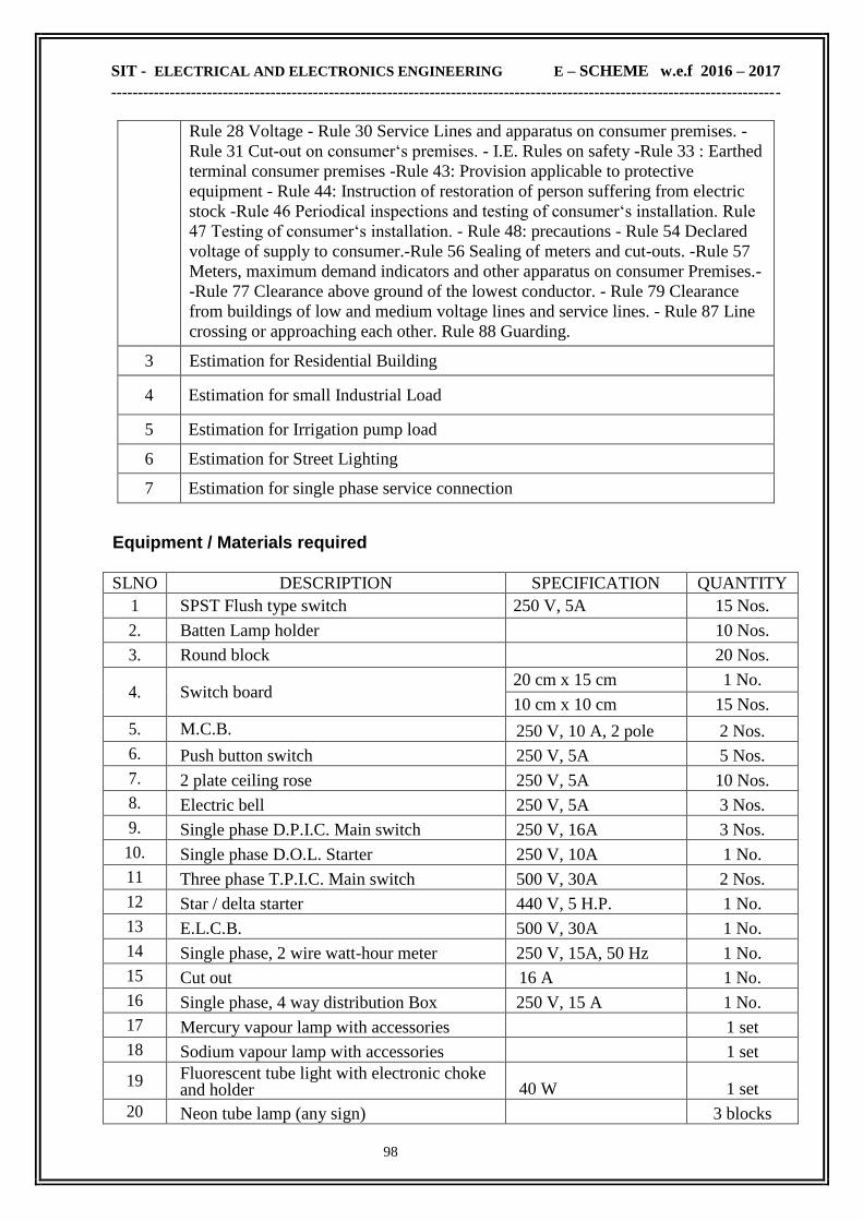
SIT - ELECTRICAL AND ELECTRONICS ENGINEERING E – SCHEME w.e.f 2016 – 2017
------------------------------------------------------------------------------------------------------------------------------
98
Rule 28 Voltage - Rule 30 Service Lines and apparatus on consumer premises. -
Rule 31 Cut-out on consumer‗s premises. - I.E. Rules on safety -Rule 33 : Earthed
terminal consumer premises -Rule 43: Provision applicable to protective
equipment - Rule 44: Instruction of restoration of person suffering from electric
stock -Rule 46 Periodical inspections and testing of consumer‗s installation. Rule
47 Testing of consumer‗s installation. - Rule 48: precautions - Rule 54 Declared
voltage of supply to consumer.-Rule 56 Sealing of meters and cut-outs. -Rule 57
Meters, maximum demand indicators and other apparatus on consumer Premises.-
-Rule 77 Clearance above ground of the lowest conductor. - Rule 79 Clearance
from buildings of low and medium voltage lines and service lines. - Rule 87 Line
crossing or approaching each other. Rule 88 Guarding.
3 Estimation for Residential Building
4 Estimation for small Industrial Load
5 Estimation for Irrigation pump load
6 Estimation for Street Lighting
7 Estimation for single phase service connection
Equipment / Materials required SLNO DESCRIPTION SPECIFICATION QUANTITY
1 SPST Flush type switch 250 V, 5A 15 Nos.
2. Batten Lamp holder 10 Nos.
3. Round block 20 Nos.
4. Switch board 20 cm x 15 cm 1 No.
10 cm x 10 cm 15 Nos.
5. M.C.B. 250 V, 10 A, 2 pole 2 Nos.
6. Push button switch 250 V, 5A 5 Nos.
7. 2 plate ceiling rose 250 V, 5A 10 Nos.
8. Electric bell 250 V, 5A 3 Nos.
9. Single phase D.P.I.C. Main switch 250 V, 16A 3 Nos.
10. Single phase D.O.L. Starter 250 V, 10A 1 No.
11 Three phase T.P.I.C. Main switch 500 V, 30A 2 Nos.
12 Star / delta starter 440 V, 5 H.P. 1 No.
13 E.L.C.B. 500 V, 30A 1 No.
14 Single phase, 2 wire watt-hour meter 250 V, 15A, 50 Hz 1 No.
15 Cut out 16 A 1 No.
16 Single phase, 4 way distribution Box 250 V, 15 A 1 No.
17 Mercury vapour lamp with accessories 1 set
18 Sodium vapour lamp with accessories 1 set
19 Fluorescent tube light with electronic choke and holder 40 W 1 set
20 Neon tube lamp (any sign) 3 blocks

SIT - ELECTRICAL AND ELECTRONICS ENGINEERING E – SCHEME w.e.f 2016 – 2017
------------------------------------------------------------------------------------------------------------------------------
99
21 Two way flush type switch 250 V, 5A 10 Nos.
22 Wooden box 30 cm x 15 cm 1 No.
23 PVC pipe 1‖ Required qty
24 Saddle clips 1‖ Required qty
25 Coppor wire 2.5 sq.mm., 1.5 sq.mm Required qty
26 Bare copper wire 2.5 Sq.mm Required qty
27 Lamps (C.F.L. or Incandescent) Different ratings Required qty
28 Transformer core: EI60 type stampings 0.35mm Thickness 55 Nos
29 Readymade bobbins (EI60/21) Required qty
30 Winding coil (copper) 25 SWG, 36 SWG 37 SWG 38 SWG Required qty
31 Varnish Required qty
32 Winding machine 1 No.
33 Ceiling Fan (motor) 1 No.
34 Single phase induction motor 0.5 H.P. 50 Hz, 240 V 1 No.
COURSE OUTCOME
CO1 Able to Wire and test different circuits
CO2 Able to assemble and test different lamp circuits
CO3 Able to understand and perform different motor Windings
CO4 Able to wind and test Transformer coils
CO5 Able to Estimate Electrical material and cost for different loads
CO6 Able to understand and implement IE rules

SIT - ELECTRICAL AND ELECTRONICS ENGINEERING E – SCHEME w.e.f 2016 – 2017
------------------------------------------------------------------------------------------------------------------------------
100
2E5404.1 - MICRO CONTROLLER LAB
RATIONALE
The importance of the microcontroller based systems is well established. With the advent
of microcontroller only the world of Digital Computer found its place in every sphere of our life.
There are numerous application of this technology in the industries for control and efficient
running of machineries. It is therefore essential that the students who read about this technology
should also perform experiments to acquaint themselves with the actual working. The Assembly
Language is to be introduced in this course for practice.
OBJECTIVES
After the completion of this laboratory, the student should be able to Write a Assembly language program to perform bit level arithmetic operations.
Write a Assembly language program to perform multi bit level arithmetic operations
Write a Assembly language program to perform code conversions.
Write a Assembly language program to solving Boolean equation.
Write a Assembly language program to interfacing relay, seven segment display, LCD
display, 4x4 matrix key board ,ADC 0808 with 89C51.
Write a Assembly language program to interfacing Stepper motor and DC motor with
89C51.
SCHEME OF INSTRUCTION & EXAMINATION
Course
Code
Instruction
Credit
Scheme Of Examination
Hours /
week
Hours /
Term
Marks Duration
Internal End Exam Total
2E5404.1 4 60 2 25 75 100 3
Scheme Of Evaluation:
SLNO Description Maximum Marks
1 Program 20
2 Hexa code conversion 20
3 Execution 20
4 Result with input and output tabulation 10
5 Viva Voce 05
6 TOTAL 75
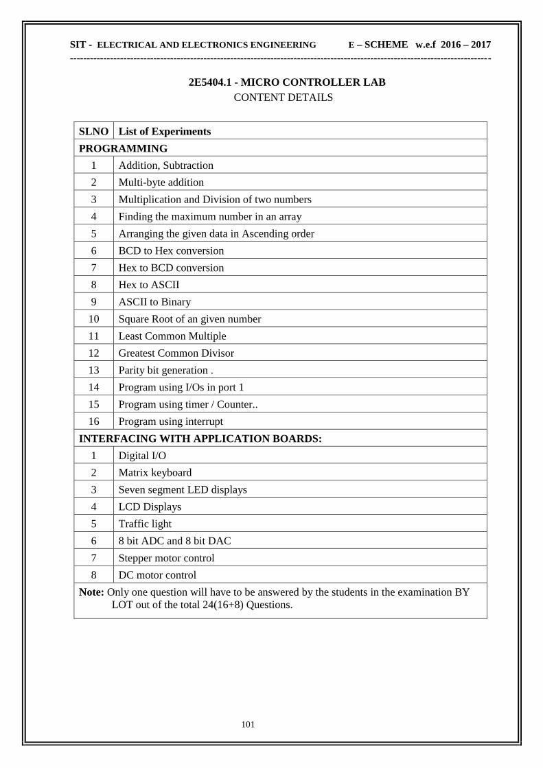
SIT - ELECTRICAL AND ELECTRONICS ENGINEERING E – SCHEME w.e.f 2016 – 2017
------------------------------------------------------------------------------------------------------------------------------
101
2E5404.1 - MICRO CONTROLLER LAB
CONTENT DETAILS
SLNO List of Experiments
PROGRAMMING
(Minimum Twelve Experiments are to be conducted)
1 Addition, Subtraction
2 Multi-byte addition
3 Multiplication and Division of two numbers
4 Finding the maximum number in an array
5 Arranging the given data in Ascending order
6 BCD to Hex conversion
7 Hex to BCD conversion
8 Hex to ASCII
9 ASCII to Binary
10 Square Root of an given number
11 Least Common Multiple
12 Greatest Common Divisor
13 Parity bit generation .
14 Program using I/Os in port 1
15 Program using timer / Counter..
16 Program using interrupt
INTERFACING WITH APPLICATION BOARDS:
(Minimum Six Experiments are to be conducted)
1 Digital I/O
2 Matrix keyboard
3 Seven segment LED displays
4 LCD Displays
5 Traffic light
6 8 bit ADC and 8 bit DAC
7 Stepper motor control
8 DC motor control
Note: Only one question will have to be answered by the students in the examination BY
LOT out of the total 24(16+8) Questions.

SIT - ELECTRICAL AND ELECTRONICS ENGINEERING E – SCHEME w.e.f 2016 – 2017
------------------------------------------------------------------------------------------------------------------------------
102
EQUIPMENTS REQUIRED
Sl.No LIST OF EQUIPMENTS Quantity
1 8051 Microcontroller Kit 12
2 Digital I/O Interface Board 1
3 Matrix keyboard Interface Board 1
4 Seven segment LED display Interface Board 1
5 LCD Display Interface Board 1
6 Traffic light Interface Board 1
7 8 bit ADC and 8 bit DAC Interface Board 1
8 STEPPER MOTOR CONTROL Interface Board 1
9 DC motor control Interface Board 1
10 Lift control Interface Board 1
11 Sending data through serial port between controller kits 1
12 Printer Interface Interface Board. 1
COURSE OUTCOME
CO1 Able to Write a Assembly language program to perform multi bit level arithmetic
operations.
CO2 Able to write a Assembly language program to perform bit level arithmetic operations.
CO3 Able to Write a Assembly language program to perform code conversions & to solving
Boolean equation.
CO4 Able to Write a Assembly language program to interfacing relay, seven segment
display, LCD display, 4x4 matrix key board ,ADC 0808 with 89C51.
CO5 Able to Write a Assembly language program to interfacing Stepper motor and DC
motor with 89C51.

SIT - ELECTRICAL AND ELECTRONICS ENGINEERING E – SCHEME w.e.f 2016 – 2017
------------------------------------------------------------------------------------------------------------------------------
103
2E5404.2- VLSI LAB
RATIONALE:
Today digital systems are designed by writing software in the form of hardware
description languages (HDLs). The most common HDLs used today are VHDL and Verilog.
This lab helps the students to improve their programming skills in the hardware description
language VHDL. The designer typically describes the behavior of the logic circuit rather than
writing traditional Boolean logic equations. In this lab Computer-aided design tools are used
to simulate the VHDL design and to synthesize the design to actual hardware.
OBJECTIVES:
After completion of this lab, the students will be able to
Write the VHDL programs for any logic design
Simulate the design
Synthesize the design
SCHEME OF INSTRUCTION & EXAMINATION
Course
Code
Instruction
Credit
Scheme Of Examination
Hours /
week
Hours /
Term
Marks Duration
Internal End Exam Total
2E5404.2 4 60 2 25 75 100 3
Scheme Of Evaluation:
SLNO Description Maximum Marks
1 Program 25
2 Execution 25
3 Result with input and output tabulation 20
4 Viva Voce 05
5 TOTAL 75

SIT - ELECTRICAL AND ELECTRONICS ENGINEERING E – SCHEME w.e.f 2016 – 2017
------------------------------------------------------------------------------------------------------------------------------
104
2E5404.2- VLSI LAB
CONTENT DETAILS
Sl.
No. LIST OF EXPERIMENTS
1 SIMULATION OF VHDL CODE FOR COMBINATIONAL CIRCUIT
Optimize a 4 variable combinational function (SOP or POS), describe it in VHDL
code and simulate it. Example: F= ( 0,5,8,9,12) in sop or pos
2 SIMULATION OF VHDL CODE FOR ARITHMETIC CIRCUITS
Design and Develop the circuit for the following arithmetic function in VHDL
Codes and Simulate it. Addition, Subtraction Multiplication (4 x 4 bits)
3 SIMULATION OF VHDL CODE FOR MULTIPLEXER
Design and develop a 2 bit multiplexer and port map the same for developing up to
8 bit multiplexer.
4 SIMULATION OF VHDL CODE FOR DEMULTIPLEXER
Design and develop an 8 output demultiplexer. Simulate the same code in the
software.
5 SIMULATION OF VHDL CODE FOR JK,T AND D FLIP FLOP
6 VHDL IMPLEMENTATION OF MULTIPLEXER
Describe the code for a multiplexer and implement it in FPGA kit in which
switches are connected for select input and for data input a LED is connected
to the output.
7 VHDL IMPLEMENTATION OF DEMULTIPLEXER
Switches are connected for select input and data input, Eight LEDs are connected to
the output of the circuit
8 VHDL IMPLEMENTATION OF 7 SEGMENT DECODER
Develop Boolean expression for 4 input variables and 7 output variables. Design
and develop a seven segment decoder in VHDL for 7 equations. A seven segment
display is connected to the output of the circuit. Four switches are connected to the
input. The 4 bit input is decoded to 7 segment equivalent.
9 VHDL IMPLEMENTATION OF 7 SEGMENT DECODER BY LUT
Develop a 7 segment decoder using Look up table. Describe the seven segment
decoder in VHDL using developed LUT. A seven segment display is connected to
the output of the circuit. Four switches are connected to the input. The 4 bit input
is decoded to 7 segment equivalent.
10 VHDL IMPLEMENTATION OF ENCODE
Design and develop HDL code for decimal (Octal) to BCD encoder. There will 10
input switches (or 8 switches) and 4 LEDs in the FPGA kit. The input given from
switches and it is noted that any one of the switch is active. The binary equivalent
for the corresponding input switch will be glowing in the LED as output.
11 VHDL IMPLEMENTATION OF TEST BENCH FOR A BOOLEAN
FUNCTION.

SIT - ELECTRICAL AND ELECTRONICS ENGINEERING E – SCHEME w.e.f 2016 – 2017
------------------------------------------------------------------------------------------------------------------------------
105
12 VHDL IMPLEMENTATION FOR BLINKING A LED
Develop a VHDL Code for delay and verify by simulating it. This delay output is
connected to LED. Delay is adjusted such away LED blinks for every 1 or 2 or 3
seconds
13 VHDL IMPLEMENTATION FOR BLINKING A ARRAY OF LEDS
Design and develop a VHDL Code for 4 bit binary up/down counter. Four LEDs
are connected at the output of the counter and a switch is connected in the input for
selecting up or down. The count up or down should happen in accordance to the
switch input for every one seconds.
14 VHDL IMPLEMENTATION OF A SPELLER WITH AN ARRAY OF LEDS
Design and develop VHDL Code for a 5 bit Johnson ring counter 4 bit The
LEDs are connected at the output of the counter. The speller should work for
every one seconds.
15 VHDL IMPLEMENTATION OF 7 SEGMENT DISPLAY
Design and develop a seven segment decoder in VHDL. Design and develop a 4
bit BCD counter, the output of the counter is given to seven segment decoder. A
seven segment display is connected to the output of the decoder. The display
shows 0,1,2 .. 9 for every one second
16 VHDL simulation and IMPLEMENTATION OF A SIPO SHIFT REGISTER
17 VHDL IMPLEMENTATION OF STEPPER MOTOR INTERFACE
COURSE OUTCOME
CO1 Able to Design and Develop the circuit for the following arithmetic function in VHDL
Codes and Simulate it. Addition, Subtraction Multiplication (4 x 4 bits)
CO2 Able to write Write the VHDL programs for any logic design.
CO3 Able to Simulate the design.
CO4 Able to Synthesis the design.
CO5 Able to understand how to interface stepper motor using VHDL

SIT - ELECTRICAL AND ELECTRONICS ENGINEERING E – SCHEME w.e.f 2016 – 2017
------------------------------------------------------------------------------------------------------------------------------
106
2E5404.3 ELECTRICAL MACHINE DESIGN LAB
RATIONALE:
Apart from theoretical knowledge of designing electrical machineries, there is a need for
students to understand the practical design considerations and their implementations. The main
aim of this course is to provide advanced knowledge and understanding about the construction
and design of the electrical machines. The course provides to the students the basis and the
methodologies to a correct design of the electrical machines (transformers, rotating AC machines
and DC machines). Innovative tools and techniques used for the design optimization of the
electrical machine for industrial, automotive and aerospace applications. The applying
knowledge and understanding capabilities will allow the students to approach the problem linked
to the design of the electrical machines.
OBJECTIVES
To provide sound knowledge about constructional details and design of various electrical
machines, in order
to study magnetic circuit parameters and thermal rating of various types of electrical
machines.
to design and assemble armature and field systems for D.C. machines.
to design and assemble core, yoke and windings of transformers.
to design stator and rotor of induction machines and synchronous machines.
SCHEME OF INSTRUCTION & EXAMINATION
Course
Code
Instruction
Credit
Scheme Of Examination
Hours /
week
Hours /
Term
Marks Duration
Internal End Exam Total
2E5404.3 4 60 2 25 75 100 3
Scheme of Evaluation:
SLNO Description Maximum Marks
For exercises requiring circuit diagram and connection
1 Circuit Diagram 25
2 Connection , Readings Taken & Tabulation (25+10) 35
3 Calculation & Result and Graph if any 10
4 Viva Voce 5
TOTAL 75
For other exercises
1 Design Particulars / Theory behind exercises 35
2 Workmanship & finishing / carrying of the test &
finding the result 35
3 Viva Voce 5
TOTAL 75

SIT - ELECTRICAL AND ELECTRONICS ENGINEERING E – SCHEME w.e.f 2016 – 2017
------------------------------------------------------------------------------------------------------------------------------
107
2E5404.3 ELECTRICAL MACHINE DESIGN LAB
CONTENT DETAILS
SNO List of Experiments
1 By simple experiment, verify the magnetic laws using Coil, permanent magnet
and Galvanometer
2 Verify the rotating magnetic field with stator and ball.
3 Measure magnetic flux using flux meter.
4 Using Crawler test the windings.
5 Design a 1 phase 1 KVA , 230/15V core type transformer and assemble the core.
6 Design a 1 phase 1KVA, 230/15V shell type transformer and assemble the core.
7 Design 3 phase 1 KVA transformer and assemble winding, core, etc.,
8 Design 3 phase 1 KVA transformer (delta/star connected) and wind one coil set.
9 Design armature for 5 KW dc machine and insert one coil set.
10 Design field pole for 5 KW dc machine and assemble one pole and insert in the body.
11 Assemble the given dc machine (pole, inter pole, armature, commutator, brush etc).
12 Design and assemble ceiling fan.
13 Design and assemble a 3 HP induction motor.
14 Design and assembled 3phase 3HP synchronous motor.
15 Dismantle and assemble a 3 phase wound rotor induction motor.
16 Design and assembled 1phasesalient pole 5KVA alternator.
Note: Only one question will have to be answered by the students in the examination BY LOT out
of the total 16 Questions
COURSE OUTCOME
CO1 Able to to understand study magnetic circuit parameters and thermal rating of various
types of electrical machines.
CO2 Able to design and assemble armature and field systems for D.C. machines.
CO3 Able to design and assemble core, yoke and windings of transformers..
CO4 Able to design stator and rotor of induction machines and synchronous machines.
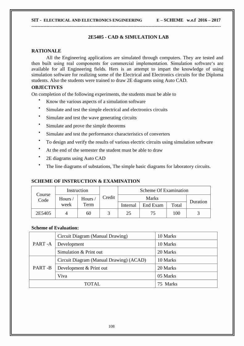
SIT - ELECTRICAL AND ELECTRONICS ENGINEERING E – SCHEME w.e.f 2016 – 2017
------------------------------------------------------------------------------------------------------------------------------
108
2E5405 - CAD & SIMULATION LAB
RATIONALE
All the Engineering applications are simulated through computers. They are tested and
then built using real components for commercial implementation. Simulation software‗s are
available for all Engineering fields. Hers is an attempt to impart the knowledge of using
simulation software for realizing some of the Electrical and Electronics circuits for the Diploma
students. Also the students were trained to draw 2E diagrams using Auto CAD.
OBJECTIVES
On completion of the following experiments, the students must be able to Know the various aspects of a simulation software
Simulate and test the simple electrical and electronics circuits
Simulate and test the wave generating circuits
Simulate and prove the simple theorems
Simulate and test the performance characteristics of converters
To design and verify the results of various electric circuits using simulation software
At the end of the semester the student must be able to draw
2E diagrams using Auto CAD
The line diagrams of substations, The simple basic diagrams for laboratory circuits.
SCHEME OF INSTRUCTION & EXAMINATION
Course
Code
Instruction
Credit
Scheme Of Examination
Hours /
week
Hours /
Term
Marks Duration
Internal End Exam Total
2E5405 4 60 3 25 75 100 3
Scheme of Evaluation:
PART -A
Circuit Diagram (Manual Drawing) 10 Marks
Development 10 Marks
Simulation & Print out 20 Marks
PART -B
Circuit Diagram (Manual Drawing) (ACAD) 10 Marks
Development & Print out 20 Marks
Viva 05 Marks
TOTAL 75 Marks
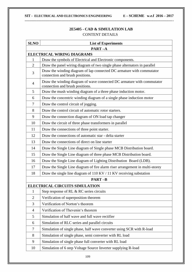
SIT - ELECTRICAL AND ELECTRONICS ENGINEERING E – SCHEME w.e.f 2016 – 2017
------------------------------------------------------------------------------------------------------------------------------
109
2E5405 - CAD & SIMULATION LAB
CONTENT DETAILS
SLNO List of Experiments
PART –A
ELECTRICAL WIRING DIAGRAMS
1 Draw the symbols of Electrical and Electronic components.
2 Draw the panel wiring diagram of two single phase alternators in parallel
3 Draw the winding diagram of lap connected DC armature with commutator
connection and brush positions.
4 Draw the winding diagram of wave connected DC armature with commutator
connection and brush positions.
5 Draw the mush winding diagram of a three phase induction motor.
6 Draw the concentric winding diagram of a single phase induction motor
7 Draw the control circuit of jogging.
8 Draw the control circuit of automatic rotor starters.
9 Draw the connection diagram of ON load tap changer
10 Draw the circuit of three phase transformers in parallel
11 Draw the connections of three point starter.
12 Draw the connections of automatic star - delta starter
13 Draw the connections of direct on line starter
14 Draw the Single Line diagram of Single phase MCB Distribution board.
15 Draw the Single Line diagram of three phase MCB Distribution board.
16 Draw the Single Line diagram of Lighting Distribution Board (LDB).
17 Draw the Single Line diagram of fire alarm riser arrangement in multi-storey
building. 18 Draw the single line diagram of 110 KV / 11 KV receiving substation
PART –B
ELECTRICAL CIRCUITS SIMULATION
1 Step response of RL & RC series circuits
2 Verification of superposition theorem
3 Verification of Norton‗s theorem
4 Verification of Thevenin‗s theorem
5 Simulation of half wave and full wave rectifier
6 Simulation of RLC series and parallel circuits
7 Simulation of single phase, half wave converter using SCR with R-load
8 Simulation of single phase, semi converter with RL load
9 Simulation of single phase full converter with RL load
10 Simulation of 6 step Voltage Source Inverter supplying R-load
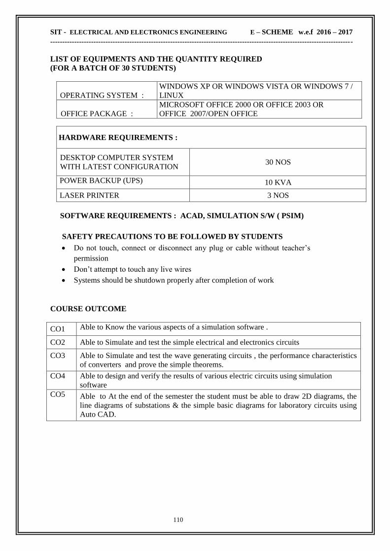
SIT - ELECTRICAL AND ELECTRONICS ENGINEERING E – SCHEME w.e.f 2016 – 2017
------------------------------------------------------------------------------------------------------------------------------
110
LIST OF EQUIPMENTS AND THE QUANTITY REQUIRED
(FOR A BATCH OF 30 STUDENTS)
OPERATING SYSTEM :
WINDOWS XP OR WINDOWS VISTA OR WINDOWS 7 /
LINUX
OFFICE PACKAGE :
MICROSOFT OFFICE 2000 OR OFFICE 2003 OR
OFFICE 2007/OPEN OFFICE
HARDWARE REQUIREMENTS :
DESKTOP COMPUTER SYSTEM
WITH LATEST CONFIGURATION 30 NOS
POWER BACKUP (UPS)
10 KVA
LASER PRINTER 3 NOS
SOFTWARE REQUIREMENTS : ACAD, SIMULATION S/W ( PSIM)
SAFETY PRECAUTIONS TO BE FOLLOWED BY STUDENTS Do not touch, connect or disconnect any plug or cable without teacher‘s
permission
Don‘t attempt to touch any live wires
Systems should be shutdown properly after completion of work
COURSE OUTCOME
CO1 Able to Know the various aspects of a simulation software .
CO2 Able to Simulate and test the simple electrical and electronics circuits
CO3 Able to Simulate and test the wave generating circuits , the performance characteristics
of converters and prove the simple theorems.
CO4 Able to design and verify the results of various electric circuits using simulation
software
CO5 Able to At the end of the semester the student must be able to draw 2D diagrams, the
line diagrams of substations & the simple basic diagrams for laboratory circuits using
Auto CAD.

SIT - ELECTRICAL AND ELECTRONICS ENGINEERING E – SCHEME w.e.f 2016 – 2017
------------------------------------------------------------------------------------------------------------------------------
111
TERM - VI

SIT - ELECTRICAL AND ELECTRONICS ENGINEERING E – SCHEME w.e.f 2016 – 2017
------------------------------------------------------------------------------------------------------------------------------
112
2E6310 - POWER SYSTEM –II
RATIONALE
Importance of Electrical Engineering is well known. This subject deals with Distribution
and utilization Electrical Energy at various levels. Industrial application of electrical engineering
such as electrolysis and illumination, electrical heating, electrical welding, electrical traction and
for electrical drives have been dealt vigorously in this paper. Students reading this paper will be
well versed in primary application of electrical power in industries.
OBJECTIVES
On completion of the following units of syllabus contents, the students must be able to Network of Electrical distribution system and its components.
Distinguish between various types of substations and bus bar arrangement
Understand the characteristics of all types of motors together with various ratings,
braking arrangements and their application
select the proper drive for industrial application
Gain knowledge about Electronic Traction system
Draw speed time curves and solve problem on max speed
Understand the concept of traction control methods of equipments
Gain knowledge on illumination‗ solve problem using laws
Understand the concept various methods of electrical heating of furnace operations
temperature control
Gain knowledge on welding methods &control equipments
SCHEME OF INSTRUCTION & EXAMINATION
Course
Code
Instruction
Credit
Scheme Of Examination
Hours /
week
Hours /
Term
Marks Duration
Internal End Exam Total
2E6310 5 75 5 25 75 100 3
TOPICS AND ALLOCATION OF HOURS & MARKS :
Unit No Name of the Topic Hours Marks
I Distribution 13 15
II Industrial Drives 13 15
III Electric Traction 13 15
IV Illumination 13 15
V Electric Heating And Welding 12 15
Revision 05
Cycle Tests and Model Examination 07
Total 75 75

SIT - ELECTRICAL AND ELECTRONICS ENGINEERING E – SCHEME w.e.f 2016 – 2017
------------------------------------------------------------------------------------------------------------------------------
113
2E6310 - POWER SYSTEM –II
CONTENT DETAILS
UNIT I : DISTRIBUTION
1.1 SUBSTATION: Introduction-Sub stations-classification of sub stations-Indoor and
outdoor S.S - Gas insulated S.S-comparisions-Layout110/11KV Substation and 11KV/400V
Distribution Substation- substation equipments-Bus bar- Types of bus bar arrangement -
Advantages and Disadvantages.
1.2 DISTRIBUTION: Distribution system-Requirements of a Distribution system-parts of
Distribution system-Classification of Distribution systems-comparison of different
distribution systems (A.C and D.C) -A.C Distribution - Types- connection - schemes of AC
Distribution system
1.3 A.C DISTRIBUTION CALCULATIONS-Calculation of voltage at load points on
single phase distribution systems (With concentrated load only)- Distributor fed at one end,
both ends and ring mains-problems- Three phase, four wire, Star connected unbalanced load
circuit- Problems- consequence of Disconnection of Neutral in three phase four wire system
(illustration with an example)
UNIT II : INDUSTRIAL DRIVES
2.1 TYPES OF DRIVES: Introduction - Electric drive - Advantages - parts of Electric drives
- Transmission of power - Types of Electric drives-Individual, group and multi motor
drives - Advantages and disadvantages of Individual and group drive – Variable frequency
Drive.
2.2 SELECTION OF DRIVES: Factors governing the selection of motors-Nature and
classification of load Torque-Matching of speed Torque characteristics of load and motor-
Standard ratings of motor- classes of load duty cycles-Selection of motors for different duty
cycles-Selection of motors for specific application
2.3 TRACTION MOTORS AND CONTROL: Desirable characteristics of Traction motors-
Motors used for Traction purpose-Methods of starting and speed control of D.C Traction motors-
Rheostatic Control-energy saving with plain rheostatic control- series-parallel control- Energy
saving with series parallel starting - Shunt Transition -Bridge-Transition- Drum control-
contactor type bridge Transition controller - Metadyne control-multiple unit control -
Regenerative braking. Recent trends in Electric Traction-Magnetic Levitation (MEGLEV)-
Suspension systems
UNIT III : ELECTRIC TRACTION
3.1 SYSTEM OF TRACK ELECTRIFICATION : Introduction-Traction systems-
Advantages and Disadvantages of Electric Traction. Methods of supplying power-Rail
connected system and over head system-O.H. equipments-contact wire, catenary and
droppers- current collection gear for OHE-Bow and pantograph collector-Different systems of
Track Electrification-Advantages of single phase low frequency A.C. system-Booster
Transformer-Necessity- Methods of connecting B.T-Neutral sectioning.
3.2 TRACTION MECHANICS: Units and notations used in Traction mechanics- Speed time
curve for different services - simplified speed time curve-Derivation of maximum speed-crest
speed, Average speed, Schedule speed (definitions only)-Tractive effort and power
requirement- Specific energy output- specific energy consumption

SIT - ELECTRICAL AND ELECTRONICS ENGINEERING E – SCHEME w.e.f 2016 – 2017
------------------------------------------------------------------------------------------------------------------------------
114
UNIT IV : ILLUMINATION
4.1 DEFINITIONS: Introduction - Definition and units of different terms used in illumination -
plane Angle, Solid angle, Light,. Luminous flux, Luminous Intensity, Luminous Efficacy
candle power, Lumen, Illumination, M.S.C.P, M.H.C.P, M.H.S.C.P- Reduction factor,
Luminance, glare Lamp efficiency. Space-height ratio, Depreciation factor Utilization
factor, waste light factor, Absorption factor, Beam factor, Reflection factor
4.2 REQUIREMENTS OF GOOD LIGHTING SYSTEM Laws of Illumination-problems.
Types of lighting scheme- Factors to be considered while designing lighting scheme- Design of
lighting Scheme (Indoor and outdoor)- Problems- Lighting systems- Factory lighting, Flood
lighting, Street lighting.
4.3 SOURCES OF LIGHT: Fluorescent Lamp , Sodium vapour lamp, High pressure
mercury vapour lamp, induction lamps - Energy saving lamps (C.F.L and L.E.D lamps) -
Stroboscopic Effect – Troubleshooting of Fluorescent Lamps -Energy saving consideration for
fluorescent lamp. .
UNIT V : ELECTRIC HEATING AND WELDING
5.1 ELECTRIC HEATING: Introduction -Advantages of Electric heating-modes of heat
transfer- classification of Electric Heating - Power frequency electric heating- Direct and
Indirect resistance heating-Infrared heating-Arc heating -High frequency Electric heating-
Induction heating –Eddy current heating and Dielectric heating.
5.2 ELECTRIC FURNACES: Resistance furnace-Requirements of Heating elements-
commonly used heating element materials - Resistance furnace for special purposes-
Temperature control of resistance furnace-Arc furnace -Direct and Indirect Arc furnace-
Temperature control of Arc furnace-Reasons for employing low voltage and high current supply
–Induction furnace-Direct and Indirect core type Induction furnace - coreless Induction
furnace-Power supply for coreless Induction furnace.
5.3 ELECTRIC WELDING: Introduction-Types of Electric welding-Requirements of good
weld- Preparation of work -Resistance welding- Butt welding, Spot welding, Seam welding,
Projection welding and Flash welding-Arc welding-Carbon Arc welding, metal Arc welding,
Atomic hydrogen Arc welding, Inert gas metal arc welding-Comparison between Resistance
and Arc welding. Radiation welding -Ultrasonic welding, Electron beam welding, LASER
beam welding-Electric welding equipments (A.C. and D.C).
TEXT BOOK :
Sl.no. Name Of The Book Author Publisher
1 A Course in Electrical Power
4th Edition 1971 J.B. Gupta
Katson Publishing House ,
New Delhi

SIT - ELECTRICAL AND ELECTRONICS ENGINEERING E – SCHEME w.e.f 2016 – 2017
------------------------------------------------------------------------------------------------------------------------------
115
REFERENCE BOOKS:
Sl.no. Name Of The Book Author Publisher
1 Electric Power
5th Edition 1976 S.L. Uppal
Khanna Publishers,
New Delhi
2 A course in Electric Power
9th Edition 1987
M.L.Soni, P.V.Gupta &
U.S.Bhatnagar
Dhanpat Rai & Sons,
New Delhi
3 Modern Electric Traction
3rd Edition Reprint 2013 H. Partab
Dhanpat Rai & Sons,
New Delhi..
4 Electrical Power Distribution
6th Ed. 2011 A.S. Pabla
Tata Mc.Graw Hill ,
New Delhi.
7 Electric Drives:concepts and
Applications , 2nd Ed. 2011 Vedam Subrahmanyam
Tata Mc.Graw Hill ,
New Delhi.
ONLINE RESOURCES
www.electrical4u.com/electrical-drives/
www.electrical-engineering-portal.com/download-center/books-and-guides/
COURSE OUTCOME
CO1
Able to Understand the concepts of Network of Electrical distribution system and its
components.
Able to Distinguish between various types of substations and bus bar arrangement
CO2
Able to Understand the characteristics of all types of motors together with various
ratings, braking arrangements and their application. Able to select the proper drive for
industrial application
CO3 Able to Gain knowledge about Electronic Traction system
CO4 Able to Understand the concept of traction control methods of equipments and also
concept various methods of electrical heating of furnace operations temperature control
CO5 Gain knowledge on illumination‗ solve problem using laws . Gain knowledge on
welding methods &control equipments

SIT - ELECTRICAL AND ELECTRONICS ENGINEERING E – SCHEME w.e.f 2016 – 2017
------------------------------------------------------------------------------------------------------------------------------
116
2E6311 - POWER ELECTRONICS
RATIONALE
Power Electronics plays a very vital role in the field of control engineering specifically in the
modern industries as they mostly use electronic controls, which are more efficient, effective and
precise as compare to the conventional methods. The concept of power electronics is to give
broad base Knowledge of power Electronics and its industrial application. It encompasses the
topics like power Semiconductor devices, SCR control Mechanism, Controlled rectifier, chopper,
Inverter & Cycloconvertor. The industrial application will enable the students to gather
knowledge of Industries & automation.
OBJECTIVES
On completion of this unit the student should be able to: o Explain the characteristics of Thyristor family.
o Draw and explain the working of trigger circuits.
o Draw and explain the operation of commutation circuits.
o State the applications of trigger and commutation circuits.
o Familiarize the phase controlled rectifier
o Know the applications of the phase controlled rectifier
o Draw and describe the working of half wave controlled rectifier circuit with R and
RL load
o Draw and explain the working of single phase semiconverter bridge and single
phase full converter Bridge for RL load.
o Draw and explain the operation of single phase and three phase full converter
with RL load
o Study the complete protection of converter circuits
o Understand the working choppers and inverters
o Describe the various methods of inverters with circuit diagram
o Understand the control of DC Drives
o Know the various methods of speed control of DC drives
o Learn the different types of power factor improvement in phase controlled
converter
o Familiarize the control of DC and AC drives
o Know the torque - speed characteristics of three phase induction motor
o Study the speed control of three phase induction motor
o Understand the closed loop control of AC drive
o Know the operation of single phase and three phase cyclo converter

SIT - ELECTRICAL AND ELECTRONICS ENGINEERING E – SCHEME w.e.f 2016 – 2017
------------------------------------------------------------------------------------------------------------------------------
117
SCHEME OF INSTRUCTION & EXAMINATION
Course
Code
Instruction
Credit
Scheme Of Examination
Hours /
week
Hours /
Term
Marks Duration
Internal End Exam Total
2E6311 5 75 5 25 75 100 3
TOPICS AND ALLOCATION OF HOURS & MARKS :
Unit No Name of the Topic Hours Marks
I Overview Of Power Electronics
12 15
II Line Commutated Power Control Circuits
13 15
III Forced Commutated Power Control Circuits
13 15
IV Applications Of Power Electronics
13 15
V Motor Drive Applications
12 15
Revision 05
Cycle Tests and Model Examination 07
Total 75 75
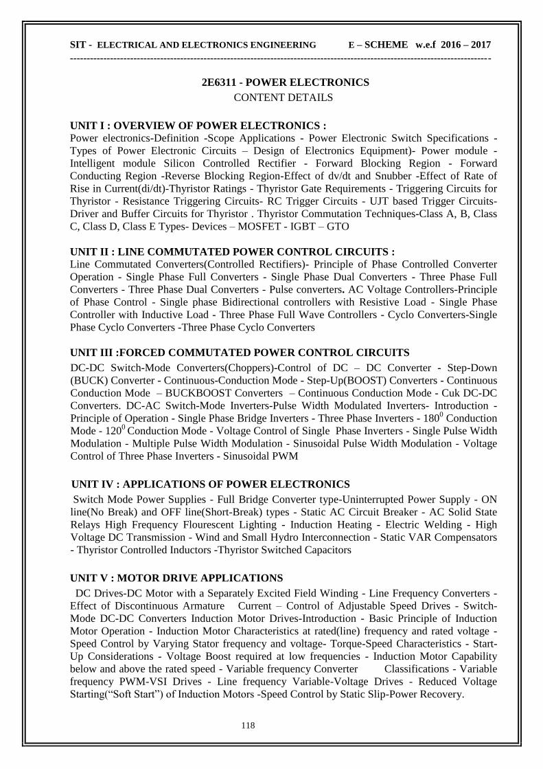
SIT - ELECTRICAL AND ELECTRONICS ENGINEERING E – SCHEME w.e.f 2016 – 2017
------------------------------------------------------------------------------------------------------------------------------
118
2E6311 - POWER ELECTRONICS
CONTENT DETAILS
UNIT I : OVERVIEW OF POWER ELECTRONICS : Power electronics-Definition -Scope Applications - Power Electronic Switch Specifications -
Types of Power Electronic Circuits – Design of Electronics Equipment)- Power module -
Intelligent module Silicon Controlled Rectifier - Forward Blocking Region - Forward
Conducting Region -Reverse Blocking Region-Effect of dv/dt and Snubber -Effect of Rate of
Rise in Current(di/dt)-Thyristor Ratings - Thyristor Gate Requirements - Triggering Circuits for
Thyristor - Resistance Triggering Circuits- RC Trigger Circuits - UJT based Trigger Circuits-
Driver and Buffer Circuits for Thyristor . Thyristor Commutation Techniques-Class A, B, Class
C, Class D, Class E Types- Devices – MOSFET - IGBT – GTO
UNIT II : LINE COMMUTATED POWER CONTROL CIRCUITS :
Line Commutated Converters(Controlled Rectifiers)- Principle of Phase Controlled Converter
Operation - Single Phase Full Converters - Single Phase Dual Converters - Three Phase Full
Converters - Three Phase Dual Converters - Pulse converters. AC Voltage Controllers-Principle
of Phase Control - Single phase Bidirectional controllers with Resistive Load - Single Phase
Controller with Inductive Load - Three Phase Full Wave Controllers - Cyclo Converters-Single
Phase Cyclo Converters -Three Phase Cyclo Converters
UNIT III :FORCED COMMUTATED POWER CONTROL CIRCUITS
DC-DC Switch-Mode Converters(Choppers)-Control of DC – DC Converter - Step-Down
(BUCK) Converter - Continuous-Conduction Mode - Step-Up(BOOST) Converters - Continuous
Conduction Mode – BUCKBOOST Converters – Continuous Conduction Mode - Cuk DC-DC
Converters. DC-AC Switch-Mode Inverters-Pulse Width Modulated Inverters- Introduction -
Principle of Operation - Single Phase Bridge Inverters - Three Phase Inverters - 1800 Conduction
Mode - 1200
Conduction Mode - Voltage Control of Single Phase Inverters - Single Pulse Width
Modulation - Multiple Pulse Width Modulation - Sinusoidal Pulse Width Modulation - Voltage
Control of Three Phase Inverters - Sinusoidal PWM
UNIT IV : APPLICATIONS OF POWER ELECTRONICS
Switch Mode Power Supplies - Full Bridge Converter type-Uninterrupted Power Supply - ON
line(No Break) and OFF line(Short-Break) types - Static AC Circuit Breaker - AC Solid State
Relays High Frequency Flourescent Lighting - Induction Heating - Electric Welding - High
Voltage DC Transmission - Wind and Small Hydro Interconnection - Static VAR Compensators
- Thyristor Controlled Inductors -Thyristor Switched Capacitors
UNIT V : MOTOR DRIVE APPLICATIONS
DC Drives-DC Motor with a Separately Excited Field Winding - Line Frequency Converters -
Effect of Discontinuous Armature Current – Control of Adjustable Speed Drives - Switch-
Mode DC-DC Converters Induction Motor Drives-Introduction - Basic Principle of Induction
Motor Operation - Induction Motor Characteristics at rated(line) frequency and rated voltage -
Speed Control by Varying Stator frequency and voltage- Torque-Speed Characteristics - Start-
Up Considerations - Voltage Boost required at low frequencies - Induction Motor Capability
below and above the rated speed - Variable frequency Converter Classifications - Variable
frequency PWM-VSI Drives - Line frequency Variable-Voltage Drives - Reduced Voltage
Starting(―Soft Start‖) of Induction Motors -Speed Control by Static Slip-Power Recovery.
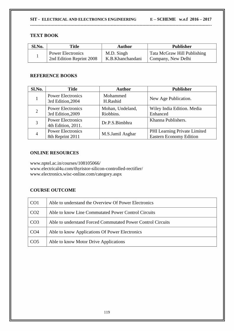
SIT - ELECTRICAL AND ELECTRONICS ENGINEERING E – SCHEME w.e.f 2016 – 2017
------------------------------------------------------------------------------------------------------------------------------
119
TEXT BOOK
Sl.No. Title Author Publisher
1 Power Electronics
2nd Edition Reprint 2008
M.D. Singh
K.B.Khanchandani
Tata McGraw Hill Publishing
Company, New Delhi
REFERENCE BOOKS
Sl.No. Title Author Publisher
1 Power Electronics
3rd Edition,2004
Mohammed
H.Rashid New Age Publication.
2 Power Electronics
3rd Edition,2009
Mohan, Undeland,
Riobbins.
Wiley India Edition. Media
Enhanced
3 Power Electronics
4th Edition, 2011. Dr.P.S.Bimbhra
Khanna Publishers.
4 Power Electronics
8th Reprint 2011 M.S.Jamil Asghar
PHI Learning Private Limited
Eastern Economy Edition
ONLINE RESOURCES
www.nptel.ac.in/courses/108105066/
www.electrical4u.com/thyristor-silicon-controlled-rectifier/
www.electronics.wisc-online.com/category.aspx
COURSE OUTCOME
CO1 Able to understand the Overview Of Power Electronics
CO2 Able to know Line Commutated Power Control Circuits
CO3 Able to understand Forced Commutated Power Control Circuits
CO4 Able to know Applications Of Power Electronics
CO5 Able to know Motor Drive Applications
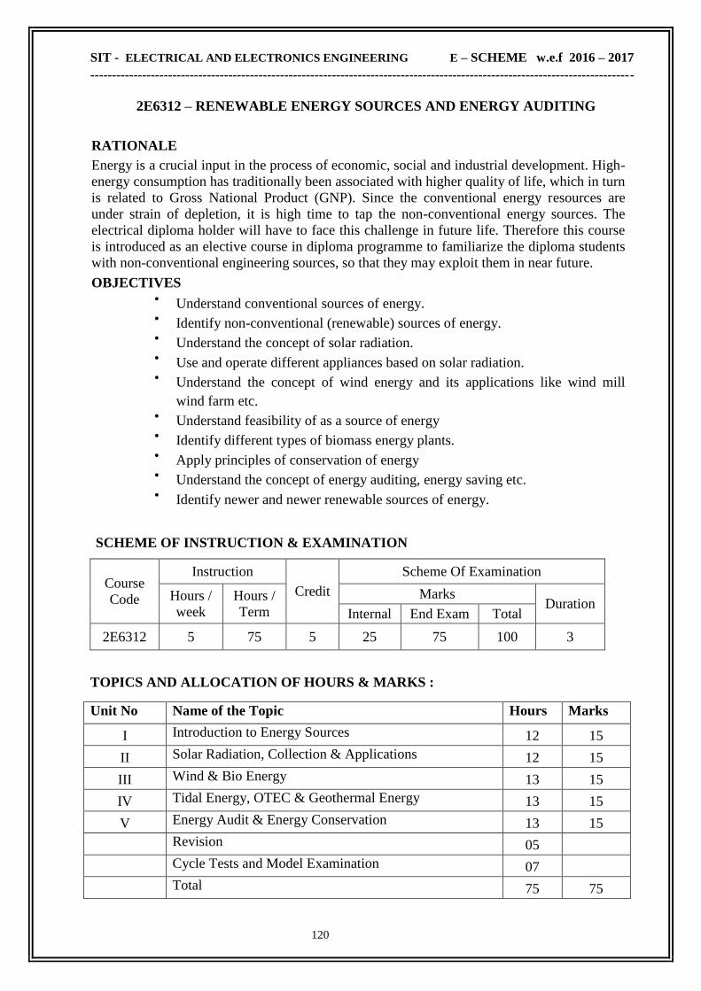
SIT - ELECTRICAL AND ELECTRONICS ENGINEERING E – SCHEME w.e.f 2016 – 2017
------------------------------------------------------------------------------------------------------------------------------
120
2E6312 – RENEWABLE ENERGY SOURCES AND ENERGY AUDITING
RATIONALE
Energy is a crucial input in the process of economic, social and industrial development. High-
energy consumption has traditionally been associated with higher quality of life, which in turn
is related to Gross National Product (GNP). Since the conventional energy resources are
under strain of depletion, it is high time to tap the non-conventional energy sources. The
electrical diploma holder will have to face this challenge in future life. Therefore this course
is introduced as an elective course in diploma programme to familiarize the diploma students
with non-conventional engineering sources, so that they may exploit them in near future.
OBJECTIVES Understand conventional sources of energy.
Identify non-conventional (renewable) sources of energy.
Understand the concept of solar radiation.
Use and operate different appliances based on solar radiation.
Understand the concept of wind energy and its applications like wind mill
wind farm etc.
Understand feasibility of as a source of energy
Identify different types of biomass energy plants.
Apply principles of conservation of energy
Understand the concept of energy auditing, energy saving etc.
Identify newer and newer renewable sources of energy.
SCHEME OF INSTRUCTION & EXAMINATION
Course
Code
Instruction
Credit
Scheme Of Examination
Hours /
week
Hours /
Term
Marks Duration
Internal End Exam Total
2E6312 5 75 5 25 75 100 3
TOPICS AND ALLOCATION OF HOURS & MARKS :
Unit No Name of the Topic Hours Marks
I Introduction to Energy Sources 12 15
II Solar Radiation, Collection & Applications 12 15
III Wind & Bio Energy 13 15
IV Tidal Energy, OTEC & Geothermal Energy 13 15
V Energy Audit & Energy Conservation 13 15
Revision 05
Cycle Tests and Model Examination 07
Total 75 75

SIT - ELECTRICAL AND ELECTRONICS ENGINEERING E – SCHEME w.e.f 2016 – 2017
------------------------------------------------------------------------------------------------------------------------------
121
2E6312 – RENEWABLE ENERGY SOURCES AND ENERGY AUDITING
CONTENT DETAILS
UNIT I : INTRODUCTION TO ENERGY SOURCES & SOLAR RADIATION
1.1 INTRODUCTION TO ENERGY SOURCES: Primary energy Sources -Secondary fuels -
Supplement sources- Energy consumption as a measure of prosperity - World energy futures -
Conclusions of the study on alternate energy strategies
1.2 CONVENTIONAL SOURCES: Energy sources and their availability -Commercial or
conventional energy sources - Coal, Oil, Agriculture and Organic base
1.3 NON-CONVENTIONAL SOURCES: Solar energy, Wind energy. Energy from
Biomass, Energy from Biogas, Energy from ocean, Tidal energy , Geothermal energy , Hydrogen
energy , Fuel cells - Thermionic Convertor- Thermo electric power -Renewable energy
sources - Advantages - Obstacles to the implementation - Prospects of renewable energy sources
- World renewable energy resources.
UNIT II : SOLAR RADIATION, COLLECTION & APPLICATIONS
2.1 SOLAR RADIATION: Solar constant - solar radiation at earth‗ s surface -Beam and diffuse
solar radiation - Solar radiation measurements - Angstrom Compensation pyrheliometer - Abbot
silver disk pyrheliometer -Eppley pyrheliometer Yellot solarimeter -Suryamapi
2.2 SOLAR ENERGY COLLECTION: Introduction - Flat plate collectors - Typical liquid
collector - Heat transport system - Advantages of flat -Plate collectors - Concentrating collector
(focusing type) - Parabolic trough collector - Fresnel lens collector - Point focusing collector
(paraboloidal type) - Concentrating collectors (Non focusing type) -Compound parabolic
concentrator - Advantages & Disadvantages of concentrating collectors over flat plate
collectors - Selective absorber coatings -Characteristics of absorber coatings.
2.3 SOLAR ENERGY APPLICATIONS: Introduction - solar water heating, passive
heating system & active heating system - space cooling - absorption air conditioning -
intermittent absorption cooling - solar thermal electric conversion - Solar electric
power generation - ON Grid and OFF Grid connection of Solar Power Plan - Principles of
solar cells - Photovoltaic system for power generation - Solar photovoltaic arrays -
Storage batteries - Inverters - Applications of solar PV system - Advantages and
Disadvantages of PV solar energy conversion - Solar distillation - Solar pumping - Solar
furnace - Solar green houses - Advantages -Solar production of hydrogen
UNIT III : WIND & BIO ENERGY
3.1 INTRODUCTION: Introduction to wind energy - basic principles of wind energy
conversion - nature of wind - power in the wind -maximum power - forces on the blade -
wind energy conversion
3.2 WIND ENERGY GENERATION: Small producers and large producers -wind data &
(qualitative treatment only) energy estimation -site selection consideration - Basic components of
wind energy conversion systems - classifications of WECS - advantages and
disadvantages of WECS generating system - scheme of electric generation - generator control -
load control -energy storage - applications of wind energy - wind energy in India -prospects
3.3 BIO ENERGY : Introduction to biomass - Biomass conversion Technologies -
wet process and dry process - Biogas generation - classification of biogas plants - continuous
& batch types - The dome and the drum types -Types of Biogas plants - Floating gas holder -
Fixed dome digestor -Comm y biogas plants - Materials used for biogas generation - Utilistion
of biogas - methods of obtaining energy from Biomass Combustion - Anerobic digestion
Pyrolsis - Hydrolyses and Ethanol Fermentation - Gasifier - Classifications - Applications
of Gasifiers
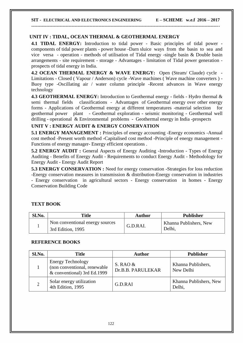
SIT - ELECTRICAL AND ELECTRONICS ENGINEERING E – SCHEME w.e.f 2016 – 2017
------------------------------------------------------------------------------------------------------------------------------
122
UNIT IV : TIDAL, OCEAN THERMAL & GEOTHERMAL ENERGY
4.1 TIDAL ENERGY: Introduction to tidal power - Basic principles of tidal power -
components of tidal power plants - power house -Darn sluice ways from the basin to sea and
vice versa - operation - methods of utilisation of Tidal energy -single basin & Double basin
arrangements - site requirement - storage - Advantages - limitation of Tidal power generation -
prospects of tidal energy in India.
4.2 OCEAN THERMAL ENERGY & WAVE ENERGY: Open (Steam/ Claude) cycle -
Limitations - Closed ( Vapour / Anderson) cycle -Wave machines ( Wave machine converters ) -
Buoy type -Oscillating air / water column principle -Recent advances in Wave energy
technology
4.3 GEOTHERMAL ENERGY: Introduction to Geothermal energy - fields - Hydro thermal &
semi thermal fields classifications - Advantages of Geothermal energy over other energy
forms - Applications of Geothermal energy at different temperatures -material selection for
geothermal power plant - Geothermal exploration - seismic monitoring - Geothermal well
drilling - operational & Environmental problems - Geothermal energy in India -prospects
UNIT V : ENERGY AUDIT & ENERGY CONSERVATION
5.1 ENERGY MANAGEMENT : Principles of energy accounting -Energy economics -Annual
cost method -Present worth method -Capitalised cost method -Principle of energy management -
Functions of energy manager- Energy efficient operations .
5.2 ENERGY AUDIT : General Aspects of Energy Auditing -Introduction - Types of Energy
Auditing - Benefits of Energy Audit - Requirements to conduct Energy Audit - Methodology for
Energy Audit - Energy Audit Report
5.3 ENERGY CONSERVATION : Need for energy conservation -Strategies for loss reduction
-Energy conservation measures in transmission & distribution-Energy conservation in industries
- Energy conservation in agricultural sectors - Energy conservation in homes - Energy
Conservation Building Code
TEXT BOOK
Sl.No. Title Author Publisher
1 Non conventional energy sources
3rd Edition, 1995 G.D.RAI.
Khanna Publishers, New
Delhi,
REFERENCE BOOKS
Sl.No. Title Author Publisher
1
Energy Technology
(non conventional, renewable
& conventional) 3rd Ed.1999
S. RAO &
Dr.B.B. PARULEKAR
Khanna Publishers,
New Delhi
2 Solar energy utilization
4th Edition, 1995 G.D.RAI
Khanna Publishers, New
Delhi,

SIT - ELECTRICAL AND ELECTRONICS ENGINEERING E – SCHEME w.e.f 2016 – 2017
------------------------------------------------------------------------------------------------------------------------------
123
ONLINE RESOURCES
www.vssut.ac.in/lecture_notes/lecture1428910296.pdf
www. eia.gov/energyexplained/?page=renewable_home
www.renewableenergyworld.com/index/tech.html
COURSE OUTCOME
CO1 Able to know various Energy Sources
CO2 Able to understand Solar Radiation, Collection & Applications
CO3 Able to understand the concept of Wind & Bio Energy
CO4 Able to understand the concept of Tidal Energy, OTEC & Geothermal Energy
CO5 Able to understand the concept of Energy Audit & Energy Conservation
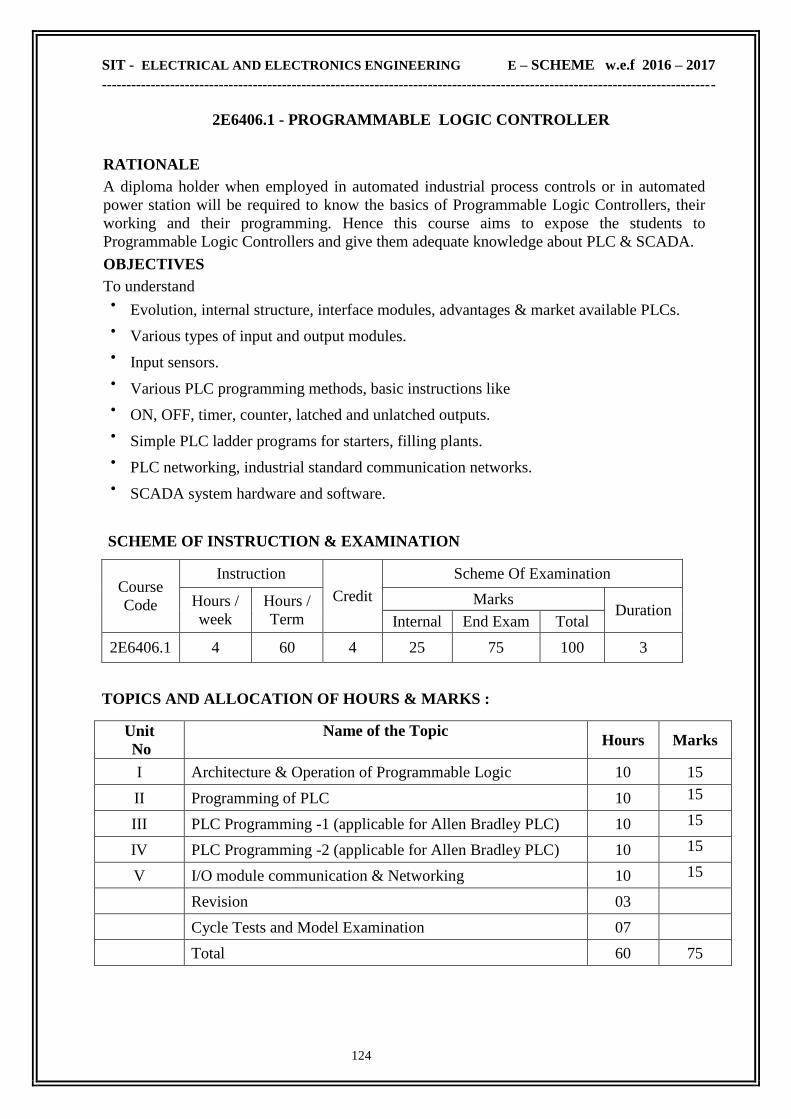
SIT - ELECTRICAL AND ELECTRONICS ENGINEERING E – SCHEME w.e.f 2016 – 2017
------------------------------------------------------------------------------------------------------------------------------
124
2E6406.1 - PROGRAMMABLE LOGIC CONTROLLER
RATIONALE
A diploma holder when employed in automated industrial process controls or in automated
power station will be required to know the basics of Programmable Logic Controllers, their
working and their programming. Hence this course aims to expose the students to
Programmable Logic Controllers and give them adequate knowledge about PLC & SCADA.
OBJECTIVES
To understand Evolution, internal structure, interface modules, advantages & market available PLCs.
Various types of input and output modules.
Input sensors.
Various PLC programming methods, basic instructions like
ON, OFF, timer, counter, latched and unlatched outputs.
Simple PLC ladder programs for starters, filling plants.
PLC networking, industrial standard communication networks.
SCADA system hardware and software.
SCHEME OF INSTRUCTION & EXAMINATION
Course
Code
Instruction
Credit
Scheme Of Examination
Hours /
week
Hours /
Term
Marks Duration
Internal End Exam Total
2E6406.1 4 60 4 25 75 100 3
TOPICS AND ALLOCATION OF HOURS & MARKS :
Unit
No
Name of the Topic Hours Marks
I Architecture & Operation of Programmable Logic
Controller
10 15
II Programming of PLC
10 15
III PLC Programming -1 (applicable for Allen Bradley PLC) 10 15
IV PLC Programming -2 (applicable for Allen Bradley PLC) 10 15
V I/O module communication & Networking 10 15
Revision 03
Cycle Tests and Model Examination 07
Total 60 75

SIT - ELECTRICAL AND ELECTRONICS ENGINEERING E – SCHEME w.e.f 2016 – 2017
------------------------------------------------------------------------------------------------------------------------------
125
2E6406.1 - PROGRAMMABLE LOGIC CONTROLLER
CONTENT DETAILS
UNIT I : INTRODUCTION TO PROGRAMMABLE LOGIC CONTROLLER
1.1 INTRODUCTION TO PLC : Evolution of Automation – Development of PLC -
Requirements of PLC - Features of PLC - Advantages over relay logic - components of PLC –
Types of PLC - Specifications and criteria for selection of suitable PLC.- PLC manufacturers
1.2 ARCHITECTURE OF PLC : Block diagram of PLC – principle of operation - CPU -
memory organization -I/O modules – PLC scan – power supplies to PLC
1.3 PLC PROGRAMMING LANGUAGES -Standard languages-Ladder diagram (LD) -
Function block diagram (FBD), Sequential function chart(SFC)- Statement List(STL), (each one
example program) -Symbols of a PLC Input and output contact graphical languages(IES) and
Ladder methods – program format.
UNIT II : PROGRAMMING OF PLC (Applicable for allen bradley PLC)
2.1 ADDRESSING SCHEMES & I/O COMMANDS: Input Addressing scheme in important
commercial PLCs. Output Addressing scheme in important commercial PLCs. Typical
Numbering mode. Simple instructions -Programming NC and NO contacts EXAMINE ON and
EXAMINE OFF instructions - online, offline methods–Latch and Unlatch outputs -pulse edge
evaluation
2.2 LADDER DIAGRAM: Ladder diagram of AND, OR, NOT, XOR, NAND AND NOR
gate - Equivalent ladder diagram to demonstrates De Morgan‘s theorem, Ladder diagram
practice for simple Logical expressions, Multiplexer and Demultiplexer.
UNIT III : TIMERS & COUNTERS (Applicable for allen bradley PLC)
3.1 Timer : Definition& Classification of a timer. Characteristics of PLC timer – Functions in a
timer – resetting – retentive and non retentive functions and function block format .
3.2 Counter : Operation of PLC counter- Counter parameters – Format of counter instructions &
Data file.
3.3 Instructions Used In Timer & Counter - on-delay and off-delay timer. Counter
instructions- UP/DOWN counters-Timer and Counter applications. Simple problems using
Timer.
UNIT IV : PLC ADVANCED INSTRUCTIONS (Applicable for allen bradley PLC)
4.1 Advanced instructions :Types of Instructions - Addressing data formats - Comparison
Instructions - EQU,NEQ, LES, GRT, GRQ, & LIM. - Program control instructions
4.2 Data manipulating instructions -Math instructions -Logic instructions -Data handling
instructions - Format and simple examples
4.3 Ladder logic diagram for DOL starter, Automatic Star-Delta Starter, Jogging operation of
3Φ IM, Forward and reversing operation of 3Φ IM, Fluid filling operation and 3 - floor Lift
control system.
UNIT V : I/O MODULES,COMMUNICATION & NETWORKING
5.1 INPUT/OUTPUT MODULES : Discrete input module -AC input module -DC input
module – sinking and sourcing -sensor input -special input modules– Sensors -limit switch, reed
switch, photo electric sensor, inductive proximity sensor.. Discrete output module - TTL output
module -Relay output –Isolated output module - surge suppression in output – Analog
outputs -open collector output.
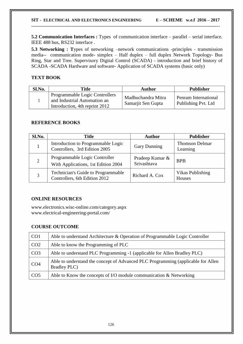
SIT - ELECTRICAL AND ELECTRONICS ENGINEERING E – SCHEME w.e.f 2016 – 2017
------------------------------------------------------------------------------------------------------------------------------
126
5.2 Communication Interfaces : Types of communication interface – parallel – serial interface.
IEEE 488 bus, RS232 interface .
5.3 Networking : Types of networking –network communications -principles - transmission
media-- communication mode- simplex – Half duplex – full duplex Network Topology- Bus
Ring, Star and Tree. Supervisory Digital Control (SCADA) - introduction and brief history of
SCADA -SCADA Hardware and software- Application of SCADA systems (basic only)
TEXT BOOK
Sl.No. Title Author Publisher
1
Programmable Logic Controllers
and Industrial Automation an
Introduction, 4th reprint 2012
Madhuchandra Mitra
Samarjit Sen Gupta
Penram International
Publishing Pvt. Ltd
REFERENCE BOOKS
Sl.No. Title Author Publisher
1 Introduction to Programmable Logic
Controllers, 3rd Edition 2005 Gary Dunning
Thomson Delmar
Learning
2 Programmable Logic Controller
With Applications, 1st Edition 2004
Pradeep Kumar &
Srivashtava BPB
3 Technician's Guide to Programmable
Controllers, 6th Edition 2012 Richard A. Cox
Vikas Publishing
Houses
ONLINE RESOURCES
www.electronics.wisc-online.com/category.aspx
www.electrical-engineering-portal.com/
COURSE OUTCOME
CO1 Able to understand Architecture & Operation of Programmable Logic Controller
CO2 Able to know the Programming of PLC
CO3 Able to understand PLC Programming -1 (applicable for Allen Bradley PLC)
CO4 Able to understand the concept of Advanced PLC Programming (applicable for Allen
Bradley PLC)
CO5 Able to Know the concepts of I/O module communication & Networking

SIT - ELECTRICAL AND ELECTRONICS ENGINEERING E – SCHEME w.e.f 2016 – 2017
------------------------------------------------------------------------------------------------------------------------------
127
2E6406.2 BIO MEDICAL INSTRUMENTATION
RATIONALE Bio medical engineering education is in the growing stage. But every year, there is a
tremendous increase in the use of modern medical equipment in the hospital and health care
industry therefore it is necessary for every student to understand the functioning of various
medical equipments. This subject to enable the students to learn the basic principles of different
biomedical instruments viz Clinical measurement, Bio - medical recorders, Therapeutic
instruments, Biotelemetry and Modern imaging techniques instruments.
OBJECTIVES After learning this subject the student will be able to understand the about
The generation of Bio-potential and its measurement using various
electrodes.
The measurement of blood pressure, lung volume, respiration rate, body temperature
and skin temperature.
The principles of operations of ECG recorder, EEG recorder, ENG recorder.
Pacemaker, various imaging techniques
The working principles of audio meter. telemetry.
The basic principle of dialysis, short wave diathermy, ventilators, telemedicine,
various types of lasers. CT and MRI scanner.
To learn about patient safety.
The various methods of accident prevention.
SCHEME OF INSTRUCTION & EXAMINATION
Course
Code
Instruction
Credit
Scheme Of Examination
Hours /
week
Hours /
Term
Marks Duration
Internal End Exam Total
2E6406.2 4 60 4 25 75 100 3
TOPICS AND ALLOCATION OF HOURS & MARKS :
Unit No Name of the Topic Hours Marks
I Bio - electric signals, electrodes and clinical
measurement 10 15
II Bio - medical recorders 10 15
III Therapeutic instruments 10 15
IV Biotelemetry and patient safety 10 15
V Modern imaging techniques 10 15
Revision 03
Cycle Tests and Model Examination 07
Total 60 75

SIT - ELECTRICAL AND ELECTRONICS ENGINEERING E – SCHEME w.e.f 2016 – 2017
------------------------------------------------------------------------------------------------------------------------------
128
2E6406.2 BIO MEDICAL INSTRUMENTATION
CONTENT DETAILS
UNIT I : BIO-ELECTRIC SIGNALS AND ELECTRODES
1.1 INTRODUCTION: Elementary ideas of cell structure, Bio – potential and their
generation – resting and action potential – propagation of action potential.
1.2 ELECTRODES: Electrodes – Micro – Skin surface – needle electrodes.
1.3 CLINICAL MEASUREMENT: Measurement of Blood pressure (direct, indirect) –
blood flow meter (Electromagnetic & ultrasonic blood flow meter) – blood pH measurement -
Measurement of Respiration rate – measurement of lung volume – heart rate measurement –
Measurement of body and skin temperature - Chromatography, Photometry, Flurometry.
UNIT II : BIO - MEDICAL RECORDERS
2.1 ELECTRO CARDIOGRAPH (ECG): Electro cardiograph (ECG) – Lead system –
ECG electrodes – ECG amplifiers – ECG recording units – analysis of ECG curves.
2.2 EEG recorder: Nervous system – EEG recorder – 10-20 lead system – recording
techniques – EEG wave types – Clinical use of EEG – brain tumour
2.3 Electro myograph (EMG) & Electro retinograph (ERG):
Electro – myograph (EMG) – EMG waves – measurement of conduction velocity – EMG
recording techniques – Electro – retinograph (ERG) Audiometer – principle – types – Basics
audiometer working.
UNIT III : THERAPEUTIC INSTRUMENTS
3.1 PACEMAKER: Cardiac pacemaker – classification – External pace makers –
implantable pacemaker – pacing techniques – programmable pacemaker
3.2 DEFIBRILLATORS & DIALYSIS: Cardiac defibrillators – types – AC and DC
defibrillators - Heart lung machine with Block diagram. Dialysis – Hemo dialysis – peritoneal
dialysis.
3.3 ENDOSCOPES & VENTILATORS: Endoscopes – Endoscopic laser coagulator and
applications – physiotherapy equipment – short wave diathermy – micro wave diathermy –
ultrasonic therapy unit (block / circuit) – Ventilators – types – modern ventilator block diagram.
UNIT IV : BIOTELEMETRY AND PATIENT SAFETY
4.1 BIOTELEMETRY: Introduction to biotelemetry – physiological – adaptable to
biotelemetry – components of a biotelemetry system – application of telemetry – elements of
biotelemetry; AM, FM transmitter and receiver –requirements for biotelemetry system – radio
telemetry with sub carrier– single channel and multi channel telemetry
4.2 TELEMEDICINE & PATIENT SAFETY: Telemedicine – introduction, working,
applications. Patient safety: Physiological effects of electric current – Micro and macro shock –
leakage current – shock hazards from electrical equipment.
4.3 SAFETY ASPECTS: Methods of Accident Prevention – Grounding – Double Insulation –
Protection by low voltage – Ground fault circuit interrupter – Isolation of patient connected parts
– Isolated power distribution system. Safety aspects in electro surgical units – burns, high
frequency current hazards, Explosion hazards.
UNIT V : MODERN IMAGING TECHNIQUES:
5.1 LASER: LASER beam properties – block diagram – operation of CO2 and NDYag LASER
– applications of LASER in medicine.
5.2 X RAY & TOMOGRAM: X ray apparatus – block diagram – operation – special
techniques in X-ray imaging – Tomogram – computerized Axial tomography
5.3 ULTRASONIC IMAGING TECHNIQUES: Ultrasonic imaging techniques – Echo
cardiography – Angiography – CT scanner - Magnetic resonance imaging techniques.

SIT - ELECTRICAL AND ELECTRONICS ENGINEERING E – SCHEME w.e.f 2016 – 2017
------------------------------------------------------------------------------------------------------------------------------
129
TEXT BOOK
Sl.No. Title Author Publisher
1 Bio- Medical Instrumentation
2nd Edition 1994 Dr.M.Arumugam Anuradha Publishers
REFERENCE BOOKS
Sl.No. Title Author Publisher
1 Handbook of Bio- Medical
Instrumentation , 3rd Ed.2015 R.S.Khandpur Tata McGraw Hill
2 Medical Electronics Kumardoss Tata McGraw Hill
3
Bio-Medical Instrumentation and
Measurement
2nd Edition 1980
Cromwell, Weibell,
Pfeiffer
PrenticeHall
international
ONLINE RESOURCES
www.eeeuniversity.com/2013/08/ei2311-biomedical-instrumentation.html
www.biomedikal.in/2009/12/lecture-notes-on-biomedical-instrumentation/
COURSE OUTCOME
CO1 Able to know Bio - electric signals, electrodes and clinical measurement
CO2 Able to know the concept of Bio - medical recorders
CO3 Able to know the concept of Therapeutic instruments
CO4 Able to know the concept of Biotelemetry and patient safety
CO5 Able to know the concept of Modern imaging techniques

SIT - ELECTRICAL AND ELECTRONICS ENGINEERING E – SCHEME w.e.f 2016 – 2017
------------------------------------------------------------------------------------------------------------------------------
130
2E6406.3 - COMPUTER HARDWARE AND NETWORKING
RATIONALE
A computer engineer should be able to install and maintain keyboard, printer, mouse, monitor
etc along with the computer system. This course provides the necessary knowledge and skills
regarding working, construction and interfacing aspects of peripherals. The students will get to
know how various peripherals communicate with central processing unit of the computer system
and pattern their respective operations.
OBJECTIVES
On completion of the following units of syllabus contents, the students must be able to Familiarize themselves the evolution of PCs.
Familiarize with the motherboards, memory chips,various Bus standards, chip sets and
processors. Understand the operation of Keyboard, Mouse and Displays.
Understand the concept of HDD, FDD and special devices.
Understand the operation of CD and DVD.
Familiarize with the working of video capture board, sound blaster cards.
Understand the different I/O ports and SMPS used in the PCs.
Understand the working of Modem, Digital camera, Printer and Scanners.
Acquire knowledge about assembling of PC,.
Understand the concept of CMOS set up program & post diagnostics software and uses.
Familiarize with the different computer networks, network media and hardware.
Understand the concept of installation & configuring network, network administration.
SCHEME OF INSTRUCTION & EXAMINATION
Course
Code
Instruction
Credit
Scheme Of Examination
Hours /
week
Hours /
Term
Marks Duration
Internal End Exam Total
2E6406.3 4 60 4 25 75 100 3
TOPICS AND ALLOCATION OF HOURS & MARKS :
Unit No Name of the Topic Hours Marks
I Motherboards and processors 10 15
II Peripherals 10 15
III I/O ports and External peripherals 10 15
IV PC Assembling and Testing 10 15
V Computer Network and Installation 10 15
Revision 03
Cycle Tests and Model Examination 07
Total 60 75
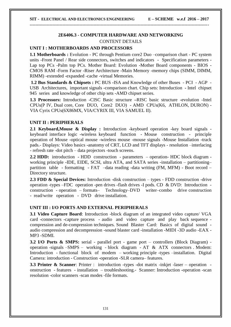
SIT - ELECTRICAL AND ELECTRONICS ENGINEERING E – SCHEME w.e.f 2016 – 2017
------------------------------------------------------------------------------------------------------------------------------
131
2E6406.3 - COMPUTER HARDWARE AND NETWORKING
CONTENT DETAILS
UNIT I : MOTHERBOARDS AND PROCESSORS
1.1 Motherboards : Evolution - PC through Pentium core2 Duo –comparison chart - PC system
units -Front Panel / Rear side connectors, switches and indicators - Specification parameters -
Lap top PCs -Palm top PCs. Mother Board: Evolution -Mother Board components - BIOS -
CMOS RAM -Form Factor -Riser Architecture -Main Memory -memory chips (SIMM, DIMM,
RIMM) -extended -expanded -cache -virtual Memories.
1.2 Bus Standards & Chipsets : PC BUS -ISA and Knowledge of other Buses - PCI - AGP -
USB Architectures, important signals -comparison chart. Chip sets: Introduction - Intel chipset
945 series and knowledge of other chip sets -AMD chipset series.
1.3 Processors: Introduction -CISC Basic structure –RISC basic structure -evolution -Intel
CPUs(P IV, Dual core, Core DUO, Core2 DUO) - AMD CPUs(K6, ATHLON, DURON) -
VIA Cyrix CPUs(6X86MX, VIA/CYRIX III, VIA SAMUEL II).
UNIT II : PERIPHERALS
2.1 Keyboard,Mouse & Display : Introduction -keyboard operation -key board signals -
keyboard interface logic -wireless keyboard function - Mouse construction - principle
operation of Mouse -optical mouse -wireless mouse -mouse signals -Mouse Installation -track
pads.- Displays: Video basics -anatomy of CRT, LCD and TFT displays - resolution –interlacing
- refresh rate -dot pitch – data projectors -touch screens.
2.2 HDD: introduction - HDD construction - parameters – operation- HDC block diagram -
working principle -IDE, EIDE, SCSI, ultra ATA, and SATA series -installation – partitioning–
partition table - formatting - FAT –data reading -data writing (FM, MFM) - Boot record –
Directory structure.
2.3 FDD & Special Devices: Introduction -disk construction – types - FDD construction -drive
operation -types –FDC operation -pen drives -flash drives -I pods. CD & DVD: Introduction -
construction - operation – formats– Technology–DVD writer–combo drive construction
- read/write operation - DVD drive installation.
UNIT III : I/O PORTS AND EXTERNAL PERIPHERALS
3.1 Video Capture Board: Introduction -block diagram of an integrated video capture/ VGA
card -connectors -capture process - audio and video capture and play back sequence -
compression and de-compression techniques. Sound Blaster Card: Basics of digital sound -
audio compression and decompression -sound blaster card -installation -MIDI -3D audio -EAX -
MP3 -SDMI.
3.2 I/O Ports & SMPS: serial - parallel port - game port – controllers (Block Diagram) -
operation -signals –SMPS – working - block diagram - AT & ATX connectors . Modem:
Introduction - functional block of modem – working principle -types –installation. Digital
Camera: introduction - Construction -operation -SLR camera– features.
3.3 Printer & Scanner: Printer : introduction -types -dot matrix -inkjet -laser – operation -
onstruction - features - installation – troubleshooting.- Scanner: Introduction -operation -scan
resolution -color scanners -scan modes -file formats.
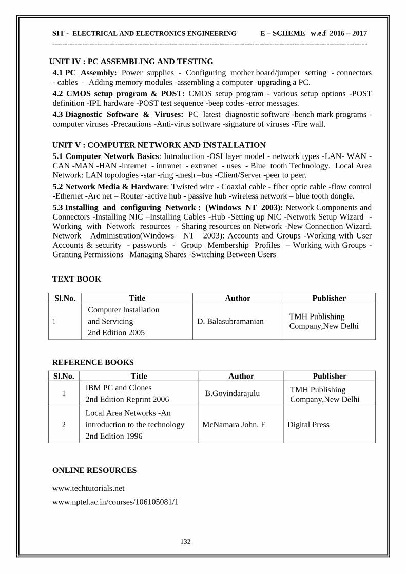
SIT - ELECTRICAL AND ELECTRONICS ENGINEERING E – SCHEME w.e.f 2016 – 2017
------------------------------------------------------------------------------------------------------------------------------
132
UNIT IV : PC ASSEMBLING AND TESTING
4.1 PC Assembly: Power supplies - Configuring mother board/jumper setting - connectors
- cables - Adding memory modules -assembling a computer -upgrading a PC.
4.2 CMOS setup program & POST: CMOS setup program - various setup options -POST
definition -IPL hardware -POST test sequence -beep codes -error messages.
4.3 Diagnostic Software & Viruses: PC latest diagnostic software -bench mark programs -
computer viruses -Precautions -Anti-virus software -signature of viruses -Fire wall.
UNIT V : COMPUTER NETWORK AND INSTALLATION
5.1 Computer Network Basics: Introduction -OSI layer model - network types -LAN- WAN -
CAN -MAN -HAN -internet - intranet - extranet - uses - Blue tooth Technology. Local Area
Network: LAN topologies -star -ring -mesh –bus -Client/Server -peer to peer.
5.2 Network Media & Hardware: Twisted wire - Coaxial cable - fiber optic cable -flow control
-Ethernet -Arc net – Router -active hub - passive hub -wireless network – blue tooth dongle.
5.3 Installing and configuring Network : (Windows NT 2003): Network Components and
Connectors -Installing NIC –Installing Cables -Hub -Setting up NIC -Network Setup Wizard -
Working with Network resources - Sharing resources on Network -New Connection Wizard.
Network Administration(Windows NT 2003): Accounts and Groups -Working with User
Accounts & security - passwords - Group Membership Profiles – Working with Groups -
Granting Permissions –Managing Shares -Switching Between Users
TEXT BOOK
Sl.No. Title Author Publisher
1
Computer Installation
and Servicing
2nd Edition 2005
D. Balasubramanian TMH Publishing
Company,New Delhi
REFERENCE BOOKS
Sl.No. Title Author Publisher
1 IBM PC and Clones
2nd Edition Reprint 2006 B.Govindarajulu TMH Publishing
Company,New Delhi
2
Local Area Networks -An
introduction to the technology
2nd Edition 1996
McNamara John. E Digital Press
ONLINE RESOURCES
www.techtutorials.net
www.nptel.ac.in/courses/106105081/1
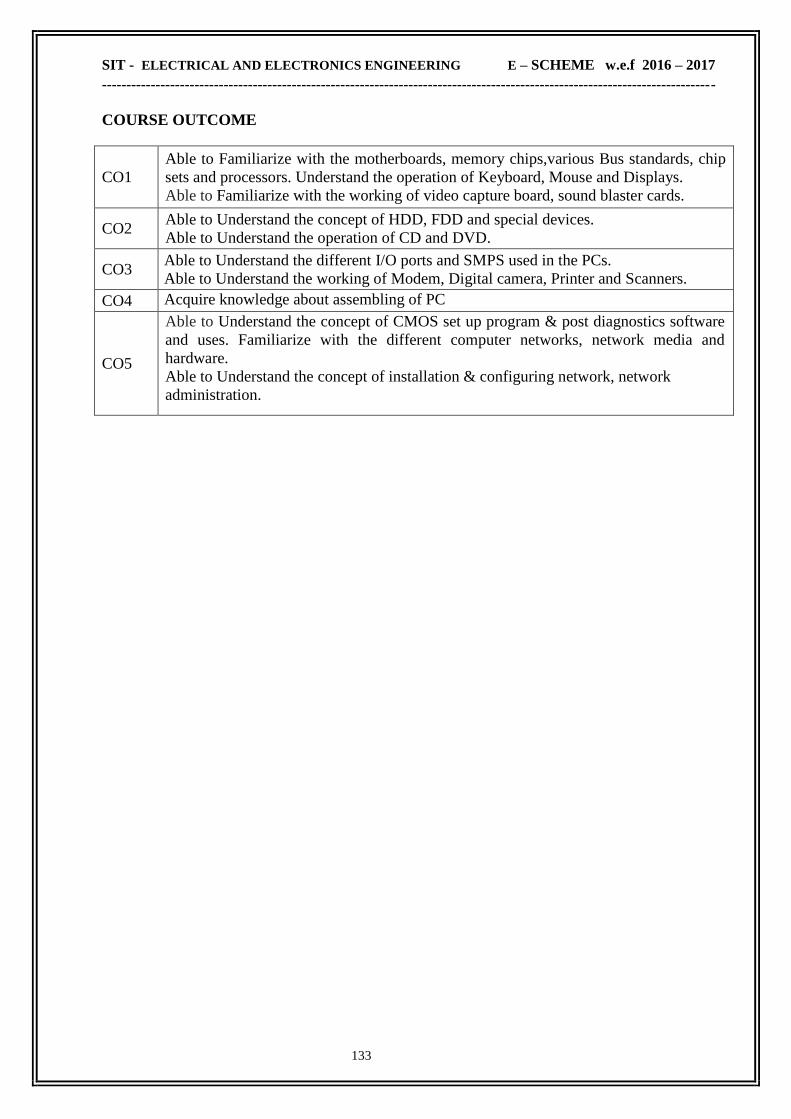
SIT - ELECTRICAL AND ELECTRONICS ENGINEERING E – SCHEME w.e.f 2016 – 2017
------------------------------------------------------------------------------------------------------------------------------
133
COURSE OUTCOME
CO1
Able to Familiarize with the motherboards, memory chips,various Bus standards, chip
sets and processors. Understand the operation of Keyboard, Mouse and Displays.
Able to Familiarize with the working of video capture board, sound blaster cards.
CO2 Able to Understand the concept of HDD, FDD and special devices.
Able to Understand the operation of CD and DVD.
CO3 Able to Understand the different I/O ports and SMPS used in the PCs.
Able to Understand the working of Modem, Digital camera, Printer and Scanners.
CO4 Acquire knowledge about assembling of PC
CO5
Able to Understand the concept of CMOS set up program & post diagnostics software
and uses. Familiarize with the different computer networks, network media and
hardware.
Able to Understand the concept of installation & configuring network, network
administration.

SIT - ELECTRICAL AND ELECTRONICS ENGINEERING E – SCHEME w.e.f 2016 – 2017
------------------------------------------------------------------------------------------------------------------------------
134
2E6313 - POWER ELECTRONICS LAB
RATIONALE
On complication this Lab, the students will familiar with power electronics devices, different
triggering circuit and application of SCR and other industrial application.
OBJECTIVES
On completion of the following experiments, the students must be able to get the knowledge about the trigger circuit
draw the input/output waveform using HCB and FCB
know the performance of lamp control using DIAC-TRIAC
learn the various techniques used for turn-off of Thyristor
draw the waveform of series/parallel inverter
draw the output waveform of DC chopper
measure the output voltage of chopper
find the performance of speed control of universal motor
understand the concept of Closed loop control of AC motor
know the performance of speed control of DC motor by varying firing angle
understand the concept of Closed loop control of DC motor
draw the output waveform of DC chopper using MOSFET/IGBT
measure the variable output voltage using PWM technique
SCHEME OF INSTRUCTION & EXAMINATION
Course
Code
Instruction
Credit
Scheme Of Examination
Hours /
week
Hours /
Term
Marks Duration
Internal End Exam Total
2E6313 6 90 3 25 75 100 3
Scheme Of Evaluation:
SL Description Maximum Marks
1 Circuit diagram 25
2 Connection 20
3 Reading/graph/result 25
4 Viva Voce 05
5 TOTAL 75

SIT - ELECTRICAL AND ELECTRONICS ENGINEERING E – SCHEME w.e.f 2016 – 2017
------------------------------------------------------------------------------------------------------------------------------
135
2E6313 - POWER ELECTRONICS LAB
CONTENT DETAILS
SLNO List of Experiments
1 Line synchronized, Ramp and Pedestal UJT trigger circuit with AC load
2 Single phase Half and Full Controlled Bridge with R load
3 Lamp control circuit using DIAC –TRIAC
4 SCR commutation circuits
5 Basic Series Inverter.
6 Single phase Parallel Inverter using MOSFET / IGBT
7 DC chopper control circuit using thyristor (any one).
8 Universal motor control circuit using TRIAC
9 Closed loop speed control of Single phase AC motor
10 DC shunt motor control circuit
11 Closed loop speed control of DC motor with loading arrangement
12 PWM based step down DC chopper using MOSFET/IGBT
13 Single phase Single pulse / Sinusoidal PWM inverter using MOSFET/IGBT
14 SMPS using MOSFET/IGBT
15 Three phase Half bridge / Full bridge Converter
Note: Only one question will have to be answered by the students in the examination BY
LOT out of the total 15 Questions.
EQUIPMENTS REQUIREMENT:
Sl.No Name of the Equipment Qty
01 Regulated Power Supply 3
02 CRO 3
03 PowerScppe 1
Digital Multimeter 3
04 Line synchronized, Ramp and Pedestal UJT trigger circuit with AC
load kit 1
05 Single phase Half and Full Controlled Bridge with R load kit 1
06 Lamp control circuit using DIAC –TRIAC kit 1
07 SCR commutation circuits kit 1
08 Basic Series Inverter. 1
09 Single phase Parallel Inverter using MOSFET / IGBT 1
10 DC chopper control circuit using thyristor (any one). 1
11 Universal motor control circuit using TRIAC 1
12 Closed loop speed control of Single phase AC motor 1

SIT - ELECTRICAL AND ELECTRONICS ENGINEERING E – SCHEME w.e.f 2016 – 2017
------------------------------------------------------------------------------------------------------------------------------
136
COURSE OUTCOME
CO1 Able to get the knowledge about the trigger circuit
Able to draw the input/output waveform using HCB and FCB
CO2 Able to know the performance of lamp control using DIAC-TRIAC
Able to learn the various techniques used for turn-off of Thyristor
CO3 Able to draw the waveform of series/parallel inverter
CO4
Able to draw the output waveform of DC chopper
Able to measure the output voltage of chopper
Able to find the performance of speed control of universal motor
Able to understand the concept of Closed loop control of AC motor
CO5
Able to know the performance of speed control of DC motor by varying firing angle
Able to understand the concept of Closed loop control of DC motor
Able to draw the output waveform of DC chopper using MOSFET/IGBT
Able to measure the variable output voltage using PWM technique
13 DC shunt motor control circuit 1
14 Closed loop speed control of DC motor with loading arrangement 1
15 PWM based step down DC chopper using MOSFET/IGBT 1
16 Single phase Single pulse / Sinusoidal PWM inverter using
MOSFET/IGBT kit 1
17 SMPS using MOSFET/IGBT kit 1
18 Three phase Half bridge / Full bridge Converter kit
1

SIT - ELECTRICAL AND ELECTRONICS ENGINEERING E – SCHEME w.e.f 2016 – 2017
------------------------------------------------------------------------------------------------------------------------------
137
2E6407.1 - PROGRAMMABLE LOGIC CONTROLLER LAB
RATIONALE
The purpose of this course is to provide the student with basic skills required to work with the
various types of PLC‗s. This course will provides the student a hands-on approach to conversion
of many conventional control circuits into PLC control circuit. Also the students will exposure
into various methods of programming used for PLC.
OBJECTIVES
After the completion of this laboratory, the student should be able to implement a ladder logic program approach to various logic gates, verification of Demorgan‗s
Theorem and demonstration of Multiplexer and De-Multiplexer .
implement a ladder logic program approach to the control circuit for various operations like
jogging, reversing control and braking of Motors.
implement a ladder logic program approach to the control circuit for various types of starters.
implement a ladder logic program approach for load shedding of transformer.
SCHEME OF INSTRUCTION & EXAMINATION
Course
Code
Instruction
Credit
Scheme Of Examination
Hours /
week
Hours /
Term
Marks Duration
Internal End Exam Total
2E6407.1 4 60 2 25 75 100 3
Scheme Of Evaluation:
SNO Description Maximum Marks
1 Ladder Logic diagram 25
2 I/O Addressing, Wiring Diagram and Connection 15
3 Execution 20
4 Result 10
5 Viva Voce 05
6 TOTAL 75
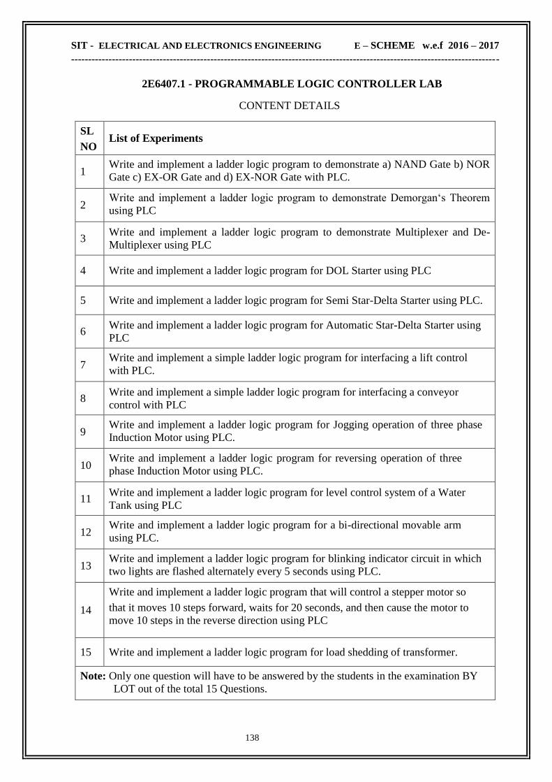
SIT - ELECTRICAL AND ELECTRONICS ENGINEERING E – SCHEME w.e.f 2016 – 2017
------------------------------------------------------------------------------------------------------------------------------
138
2E6407.1 - PROGRAMMABLE LOGIC CONTROLLER LAB
CONTENT DETAILS
SL
NO List of Experiments
1 Write and implement a ladder logic program to demonstrate a) NAND Gate b) NOR
Gate c) EX-OR Gate and d) EX-NOR Gate with PLC.
2 Write and implement a ladder logic program to demonstrate Demorgan‗s Theorem
using PLC
3
Write and implement a ladder logic program to demonstrate Multiplexer and De-
Multiplexer using PLC
4 Write and implement a ladder logic program for DOL Starter using PLC
5 Write and implement a ladder logic program for Semi Star-Delta Starter using PLC.
6 Write and implement a ladder logic program for Automatic Star-Delta Starter using
PLC
7 Write and implement a simple ladder logic program for interfacing a lift control
with PLC.
8
Write and implement a simple ladder logic program for interfacing a conveyor
control with PLC
9 Write and implement a ladder logic program for Jogging operation of three phase
Induction Motor using PLC.
10
Write and implement a ladder logic program for reversing operation of three
phase Induction Motor using PLC.
11
Write and implement a ladder logic program for level control system of a Water
Tank using PLC
12 Write and implement a ladder logic program for a bi-directional movable arm
using PLC.
13
Write and implement a ladder logic program for blinking indicator circuit in which
two lights are flashed alternately every 5 seconds using PLC.
14
Write and implement a ladder logic program that will control a stepper motor so
that it moves 10 steps forward, waits for 20 seconds, and then cause the motor to
move 10 steps in the reverse direction using PLC
15 Write and implement a ladder logic program for load shedding of transformer.
Note: Only one question will have to be answered by the students in the examination BY
LOT out of the total 15 Questions.

SIT - ELECTRICAL AND ELECTRONICS ENGINEERING E – SCHEME w.e.f 2016 – 2017
------------------------------------------------------------------------------------------------------------------------------
139
EQUIPMENTS REQUIREMENT:
COURSE OUTCOME
CO1 Able to implement a ladder logic program approach to various logic gates, verification
of Demorgan‗s Theorem and demonstration of Multiplexer and De-Multiplexer .
CO2 Able to implement a ladder logic program approach to the control circuit for various
operations like jogging, reversing control and braking of Motors.
CO3 Able to implement a ladder logic program approach to the control circuit for various
types of starters.
CO4 Able to implement a ladder logic program approach for load shedding of transformer.
CO5 Able to understand and implement control logic for process applications
Sl.No Name of the Equipment Qty
01 PLC with suitable No of I/O (various brands, Computer interface cables
software etc) 5
02 Push button switch limit switch, reed switch, photo electric sensor,
inductive proximity sensor Capacitive proximity sensor Regulated Power
Supply
5 each
03 PLC Power supply (SMPS if necessary) Required
No
04 DOL Starter Kit 2 No
05 Semi Automatic Star-Delta Starter Kit 5 No
06 Fully Automatic Star-Delta Starter Kit 2 No
07 Kit for Jogging operation of three phase Induction Motor 5 No
08 Kit for reversing operation of three phase Induction Motor 1 No
09 Kit for Level control system of a Water Tank 1 No
10 Kit for Bi-directional movable arm using PLC.
1 No
11 Kit for blinking indicator circuit with two lights 1 No
12 Stepper motor controller kit 1 No
13 Lift control Kit 1 No
14 Conveyor belt kit 2 No

SIT - ELECTRICAL AND ELECTRONICS ENGINEERING E – SCHEME w.e.f 2016 – 2017
------------------------------------------------------------------------------------------------------------------------------
140
2E6407.2 BIO-MEDICAL INSTRUMENTATION LAB
RATIONALE:
Recent advances in medical field have been fuelled by the instruments developed by
the Electronics and Instrumentation Engineers. Pacemakers, Ultrasound Machine CAT,
Medical diagnostic systems are few names which have been contributed by engineers. Now
health care industry uses many instruments which are to be looked after by instrumentation
engineers. This subject will enable the students to learn the basic principles of different
instruments/equipment used in the health care industry. The practical work done in this area
will impart skill in the use, servicing and maintenance of these instruments/equipment.
Proficiency in this area will widen the knowledge and skill of diploma holders in the field of
biomedical instrumentation.
OBJECTIVES:
On completion of the following experiments, the students must be able to
Construct and test differential, high gain and instrumentation amplifiers
Measure pH values, blood pressure, temperatures, etc,.
Handle different types of biomedical equipments
SCHEME OF INSTRUCTION & EXAMINATION
Course
Code
Instruction
Credit
Scheme Of Examination
Hours /
week
Hours /
Term
Marks Duration
Internal End Exam Total
2E6407.2 4 60 2 25 75 100 3
Scheme of Evaluation:
SLNO Description Maximum Marks
For exercises requiring circuit diagram and connection
1 Circuit Diagram 20
2 Connection 20
3 Readings Taken & Tabulation 10
4 Calculation & Result and Graph if any 20
5 Viva 5
TOTAL 75
For other exercises
1 Design Particulars / Theory behind exercises 30
2 Work menship & finishing / carrying of the test &
finding the result 40
3 Viva 5
TOTAL 75

SIT - ELECTRICAL AND ELECTRONICS ENGINEERING E – SCHEME w.e.f 2016 – 2017
------------------------------------------------------------------------------------------------------------------------------
141
2E6407.2 BIO-MEDICAL INSTRUMENTATION LAB
CONTENT DETAILS
SN
O List of Experiments
1 Construction and Testing of Differential amplifier.
2 Construction and Testing of Instrumentation amplifier.
3 Measurement of pH of given solution.
4 Measurement of Blood pressure.
5 Measurement of ECG waveform.
6 Construction and verification of pacemaker circuit.
7 Construction and testing of high gain amplifier.
8 Measurement of Body and Skin temperature
9 Study, handle and use of following instruments/Equipments:
a) Cardiac monitor.
b) Vascular probe with vasoline monitor.
c) ECG stimulator.
d) Muscle stimulator.
e) Vectorodyne electrotherapy equipment.
f) Vascular Doppler recorder.
g) Pressure plethysmograph.
h) Skin sympathetic response meter.
Note: Only one question will have to be answered by the students in the examination BY LOT
out of the total 16 Questions
COURSE OUTCOME
CO1 Able to Construct and test differential, high gain and instrumentation amplifiers
CO2 Able to Measure pH values, blood pressure, temperatures, etc,.
CO3 Able to Handle different types of biomedical equipments

SIT - ELECTRICAL AND ELECTRONICS ENGINEERING E – SCHEME w.e.f 2016 – 2017
------------------------------------------------------------------------------------------------------------------------------
142
2E6407.3 - COMPUTER HARDWARE AND NETWORKING LAB
RATIONALE
The course aims at making the students familiar with various parts of computers and how
to assemble them, and different types of peripherals desired. In addition, the course will provide
the students with necessary knowledge and skills in computer software installation and
maintenance to make him diagnose software faults.
This subject also gives the knowledge and competency to diagnose the problems in computer
hardware and peripherals and also gives the knowledge for trouble shooting for systematic repair
and maintenance of computers and computer peripherals.
OBJECTIVES
On completion of the following exercises, the students must be able to Know the various indicators, switches and connectors used in Pentium.
Familiarize the layout of SMPS, motherboard and various Disk Drives.
Configure Bios set up options.
Install various secondary storage Devices with memory partition and Formatting.
Know the various types of printer installation and to handle the troubleshooting ability.
Acquire the practical knowledge about the installation of various communication and
entertainment devices.
Handle the audio/video devices, interfacing with PC.
Setup Video-conference System..
Assemble PC system and checking the working condition.
Identify the problems in Pentium systems, software installation and rectification also.
SCHEME OF INSTRUCTION & EXAMINATION
Course
Code
Instruction
Credit
Scheme Of Examination
Hours /
week
Hours /
Term
Marks Duration
Internal End Exam Total
2E6407.3 4 60 2 25 75 100 3
Scheme Of Evaluation:
SLNO Description Maximum Marks
1 Circuit diagram 25
2 Connection 15
3 Execution 25
4 Result 05
5 Viva Voce 05
6 TOTAL 75

SIT - ELECTRICAL AND ELECTRONICS ENGINEERING E – SCHEME w.e.f 2016 – 2017
------------------------------------------------------------------------------------------------------------------------------
143
2E6407.3 - COMPUTER HARDWARE AND NETWORKING LAB
CONTENT DETAILS
SLNO List of Experiments
1
Switches, Indicators and connectors of PC: Identification of front panel indicators
and switches in a computer system of table top/ tower case model and also
identification of rear side connectors
2
PC system layout: Draw a Computer system layout and Mark the positions of
SMPS, Mother Board, FDD, HDD, and CD-Drive/DVD-Drive add on cards in
table top / tower model systems
3
Mother Board Layout: Draw the layout of Pentium IV or Pentium Dual core
Pentium Core2 DUO mother board and mark Processor, Chip set ICs. RAM,
Cache, Xtal, cooling fan, I/O slots and I/O ports and various jumper settings.
4 CMOS Setup Program: 1. Changing the Standard settings 2. Changing advanced
settings (BIOS and Chipset features)
5 Installation of FDD: 1. Install and configure an FDD in a computer system. 2.
Floppy drive diagnostics/servicing.
6
USB pen drives and I-pods. 1. Connect and enable a pen drive or I-pod in a PC. 2.
Format the pen drive or I-pod. 3. Copy files and folders from pen drive I-pod to
HDD. 4. Copy files and folders from HDD to pen drive or I-pod.
7 HDD Installation: 1. Install the given HDD. 2. Configure in CMOS-Setup
program 3. Partition the HDD using FDISK. 4. Format the Partitions.
8
Printer Installation & Troubleshooting: 1. Installing and checking a Dot-Matrix
Printer. 2. Installing and checking an Ink jet / Laser Printer. 3.Possible problems
and troubleshooting
9 Modem Installation: 1. Install and configure a Modem in a windows PC. 2. Check
the working condition of modem with PC
10
DVD Multi-recorder drive installation: 1. Install a DVD Multi-recorder drive in a
PC. 2 Configure using device driver. 3. Check the read / write operation using a cd
/ dvd.
11 Installation of Scanner: 1. Connect the given scanner with a PC. 2. Configure the
scanner with driver. 3. Check the scanner by scanning a page / a portion in a page
12 Familiarize: Scandisk, recent Anti-virus software and recent PC Diagnostic
13 Assembling a PC: Assemble a Pentium IV or Pentium Dual Core Duo system
with necessary peripherals and check the working condition of the PC.
14 Install and Configure Windows NT2003 operating system in a PC.
15 Construct Network by connecting one or two computer with a Windows NT2003
Server

SIT - ELECTRICAL AND ELECTRONICS ENGINEERING E – SCHEME w.e.f 2016 – 2017
------------------------------------------------------------------------------------------------------------------------------
144
16 install and Configure LINUX operating system in a PC
17 Construct Network by connecting one or two computer with a LINUX Server.
18 Configure the network for an Internet server
19 Add / Remove devices using Hardware Wizard
20 Add and Manage User Profile, Set permission to the users both in Windows NT
2003/ LINUX
Note: Only one question will have to be answered by the students in the examination BY
LOT out of the total 20 Questions.
COURSE OUTCOME
CO1 Able to know the various indicators, switches and connectors used in Pentium.
CO2 Able to familiarize the layout of SMPS, motherboard and various Disk Drives.
CO3 Able to configure Bios set up options.
CO4 Able to install various secondary storage Devices with memory partition and
Formatting.
CO5 Able to know the various types of printer installation and to handle the troubleshooting
ability
CO6 Able to acquire the practical knowledge about the installation of various communication
and entertainment devices.
CO7 Able to Handle the audio/video devices, interfacing with PC
CO8 Able to Setup Video-conference System
CO9 Able to assemble PC system and checking the working condition
CO10 Able to identify the problems in Pentium systems, software installation and rectification
also

SIT - ELECTRICAL AND ELECTRONICS ENGINEERING E – SCHEME w.e.f 2016 – 2017
------------------------------------------------------------------------------------------------------------------------------
145
2E6408 - PROJECT WORK
Course
Code
Instruction
Credit
Scheme Of Examination
Hours /
week
Hours /
Term
Marks Duration
Internal End Exam Total
2E6408 6 90 4 25 75 100 3
RATIONALE
Project work aims at developing skills in the students whereby they apply in totality the
knowledge and skills gained through the course in the solution of a practical problem undertaken
as a project work. The students have different aptitudes and strengths. Project work, therefore,
should match the strengths of students. For this purpose, students should be asked to identify the
type of project work, they would like to execute. It is also essential that the faculty of the
respective departments may have a brainstorming session to identify suitable project
assignments. The project assignment can be individual assignment or a group assignment. There
should not be more than 3 students if the project work is given to a group. The students should
identify themselves or be given project assignment at least two to three months in advance. The
project work identified in collaboration with industry/field organization should be preferred.
OBJECTIVES
After the completion of this laboratory, the student should be able to o Implement the theoretical and practical knowledge gained through the curriculum
into an application suitable for a real practical working environment preferably in
an industrial environment
o Develop software packages or applications to implement the actual needs of the
community. Get exposure on industrial environment and its work ethics.
o Learn and understand the gap between the technological knowledge acquired
through curriculum and the actual industrial need and to compensate it by
acquiring additional knowledge as required.
o Carry out cooperative learning through synchronous guided discussions within the
class in key dates, asynchronous document sharing and discussions, as well as to
prepare collaborative edition of the final project report.
o Expose students to the field of computing and to gain experience in software
design. Understand the facts and importance of environmental management.
o Understand and gain knowledge about disaster management.

SIT - ELECTRICAL AND ELECTRONICS ENGINEERING E – SCHEME w.e.f 2016 – 2017
------------------------------------------------------------------------------------------------------------------------------
146
SCHEME OF INSTRUCTION & EXAMINATION
Course
Code
Instruction
Credit
Scheme Of Examination
Hours /
week
Hours /
Term
Marks Duration
Internal End Exam Total
2E6408 6 90 4 25 75 100 3
Scheme of Evaluation:
2E6408 - PROJECT WORK
CONTENT DETAILS
PART-A
ENVIRONMENTAL MANAGEMENT
Introduction – Environmental Ethics – Assessment of Socio Economic Impact –
Environmental Audit – Mitigation of adverse impact on Environment – Importance of Pollution
Control – Types of Industries and Industrial Pollution.
Solid waste management – Characteristics of Industrial wastes – Methods of Collection, transfer
and disposal of solid wastes – Converting waste to energy – Hazardous waste management
Treatment technologies. Waste water management – Characteristics of Industrial effluents –
Treatment and disposal methods – Pollution of water sources and effects on human health. Air
pollution management – Sources and effects – Dispersion of air pollutants – Air pollution control
methods – Air quality management. Noise pollution management – Effects of noise on people –
Noise control methods.
PART-B
DISASTER MANAGEMENT
Introduction – Disasters due to natural calamities such as Earthquake, Rain, Flood, Hurricane,
Cyclones etc – Man made Disasters – Crisis due to fires, accidents, strikes etc – Loss of property
and life.. Disaster Mitigation measures – Causes for major disasters – Risk Identification –
Hazard Zones – Selection of sites for Industries and residential buildings – Minimum distances
from Sea – Orientation of Buildings – Stability of Structures – Fire escapes in buildings -
Cyclone shelters – Warning systems. Disaster Management – Preparedness, Response, Recovery
– Arrangements to be made in the industries / factories and buildings – Mobilization of
Marks for Report Preparation, Demo, Viva-voce 65 Marks
Marks for answers of 4 questions which is to be set by the
external examiner from the given question bank consisting of
questions in the following two topics Disaster Management and
Environmental Management. Out of four questions two questions
to appear from each of the above topics
i.e. 2 questions x 2 topics = 4 questions
4 questions x 2 ½ marks = 10 Marks
10 Marks
TOTAL 75 Marks

SIT - ELECTRICAL AND ELECTRONICS ENGINEERING E – SCHEME w.e.f 2016 – 2017
------------------------------------------------------------------------------------------------------------------------------
147
Emergency Services - Search and Rescue operations – First Aids – Transportation of affected
people – Hospital facilities – Fire fighting arrangements – Communication systems – Restoration
of Power supply – Getting assistance of neighbors / Other organizations in Recovery and
Rebuilding works – Financial commitments – Compensations to be paid – Insurances –
Rehabilitation.

SIT - ELECTRICAL AND ELECTRONICS ENGINEERING E – SCHEME w.e.f 2016 – 2017
------------------------------------------------------------------------------------------------------------------------------
148
LIST OF QUESTIONS
1. ENVIRONMENTRAL MANAGEMENT
1. What is the responsibility of an Engineer-in-charge of an Industry with respect to Public
Health?
2. Define Environmental Ethic.
3. How Industries play their role in polluting the environment?
4. What is the necessity of pollution control? What are all the different organizations you
know, which deal with pollution control?
5. List out the different types of pollutions caused by a Chemical / Textile / Leather /
Automobile / Cement factory.
6. What is meant by Hazardous waste?
7. Define Industrial waste management.
8. Differentiate between garbage, rubbish, refuse and trash based on their composition and
source.
9. Explain briefly how the quantity of solid waste generated in an industry could be reduced.
10. What are the objectives of treatments of solid wastes before disposal?
11. What are the different methods of disposal of solid wastes?
12. Explain how the principle of recycling could be applied in the process of waste
minimization.
13. Define the term ‗Environmental Waste Audit‘.
14. List and discuss the factors pertinent to the selection of landfill site.
15. Explain the purpose of daily cover in a sanitary landfill and state the minimum desirable
depth of daily cover.
16. Describe any two methods of converting waste into energy.
17. What actions, a local body such as a municipality could take when the agency appointed for
collecting & disposing the solid wastes fails to do the work continuously for number of days?
18. Write a note on Characteristics of hazardous waste.
19. What is the difference between municipal and industrial effluent ?
20. List few of the undesirable parameters / pollutants anticipated in the effluents from oil
refinery industry / thermal power plants / textile industries / woolen mills / dye industries /
electroplating industries / cement plants / leather industries (any two may be asked)
21. Explain briefly the process of Equalization and Neutralization of waste water of varying
characteristics discharged from an Industry.
22. Explain briefly the Physical treatments ―Sedimentation‖ and ―Floatation‖ processes in the
waste water treatment.
23. Explain briefly when and how chemical / biological treatments are given to the waste
water.
24. List the four common advanced waste water treatment processes and the pollutants they
remove.
25. Describe refractory organics and the method used to remove them from the effluent.
26. Explain biological nitrification and de-nitrification.
27. Describe the basic approaches to land treatment of Industrial Effluent.
28. Describe the locations for the ultimate disposal of sludge and the treatment steps needed
prior to ultimate disposal.
29. List any five Industries, which act as the major sources for Hazardous Air Pollutants.
30. List out the names of any three hazardous air pollutants and their effects on human health.
31. Explain the influence of moisture, temperature and sunlight on the severity of air pollution
effects on materials.
32. Differentiate between acute and chronic health effects from Air pollution.
33. Define the term Acid rain and explain how it occurs.

SIT - ELECTRICAL AND ELECTRONICS ENGINEERING E – SCHEME w.e.f 2016 – 2017
------------------------------------------------------------------------------------------------------------------------------
149
34. Discuss briefly the causes for global warming and its consequences
35. Suggest suitable Air pollution control devices for a few pollutants and sources.
36. Explain how evaporative emissions and exhaust emissions are commonly controlled.
37. What are the harmful elements present in the automobile smokes? How their presence
could be controlled?
38. What is the Advantage of Ozone layer in the atmosphere? State few reasons for its
destruction.
39. Explain the mechanism by which hearing damage occurs.
40. List any five effects of noise other than hearing damage.
41. Explain why impulsive noise is more dangerous than steady state noise.
42. Explain briefly the Source – Path – Receiver concept of Noise control.
43. Where silencers or mufflers are used ? Explain how they reduce the noise.
44. Describe two techniques to protect the receiver from hearing loss when design / redress for
noise control fail.
45. What are the problems faced by the people residing along the side of a railway track and
near to an Airport? What provisions could be made in their houses to reduce the problem?
2. DISASTER MANAGEMENT
1. What is meant by Disaster Management? What are the different stages of Disaster
management?
2. Differentiate Natural Disasters and Man made Disasters with examples.
3. Describe the necessity of Risk identification and Assessment Surveys while planning a
project.
4. What is Disasters recovery and what does it mean to an Industry?
5. What are the factors to be considered while planning the rebuilding works after a major
disaster due to flood / cyclone / earthquake? (Any one may be asked)
6. List out the public emergency services available in the state, which could be approached for
help during a natural disaster.
7. Specify the role played by an Engineer in the process of Disaster management.
8. What is the cause for Earthquakes? How they are measured? Which parts of India are more
vulnerable for frequent earthquakes?
9. What was the cause for the Tsunami 2004 which inflicted heavy loss to life and property
along the coast of Tamilnadu ? Specify its epicenter and magnitude.
10. Specify the Earthquake Hazard Zones in which the following towns of Tamilnadu lie:
(a) Chennai (b) Nagapattinam (c) Coimbatore (d) Madurai (e) Salem.
11. Which parts of India are experiencing frequent natural calamities such as (a) heavy rain fall
(b) huge losses due to floods (c) severe cyclones
12. Define basic wind speed. What will be the peak wind speed in (a) Very high damage risk
zone – A, (b) High damage risk zone, (c) Low damage risk zone.
13. Specify the minimum distance from the Sea shore and minimum height above the mean sea
level, desirable for the location of buildings.
14. Explain how the topography of the site plays a role in the disasters caused by floods and
cyclones.
15. Explain how the shape and orientation of buildings could reduce the damages due to
cyclones.
16. What is a cyclone shelter ? When and where it is provided? What are its requirements?
17. What Precautionary measures have to be taken by the authorities before opening a dam for
discharging the excess water into a canal/river ?
18. What are the causes for fire accidents ? Specify the remedial measures to be taken in
buildings to avoid fire accidents.

SIT - ELECTRICAL AND ELECTRONICS ENGINEERING E – SCHEME w.e.f 2016 – 2017
------------------------------------------------------------------------------------------------------------------------------
150
19. What is a fire escape in multistoried buildings ? What are its requirements?
20. How the imamates of a multistory building are to be evacuted in the event of a fire/Chemical
spill/Toxic Air Situation/ Terrorist attack, (any one may be asked).
21. Describe different fire fighting arrangements to be provided in an Industry.
22. Explain the necessity of disaster warning systems in Industries.
23. Explain how rescue operations have to be carried out in the case of collapse of buildings
due to earthquake / blast / Cyclone / flood.
24. What are the necessary steps to be taken to avoid dangerous epidemics after a flood
disaster?
25. What relief works that have to be carried out to save the lives of workers when the factory
area is suddenly affected by a dangerous gas leak / sudden flooding ?
26. What are the difficulties faced by an Industry when there is a sudden power failure? How
such a situation could be managed?
27. What are the difficulties faced by the Management when there is a group clash between the
workers? How such a situation could be managed?
28. What will be the problems faced by the management of an Industry when a worker dies
because of the failure of a mechanical device due to poor maintenance? How to manage such
a situation ?
29. What precautionary measures have to be taken to avoid accidents to labourers in the
Industry in a workshop / during handling of dangerous Chemicals / during construction of
buildings / during the building maintenance works.
30. Explain the necessity of medical care facilities in an Industry / Project site.
31. Explain the necessity of proper training to the employees of Industries dealing with
hazardous products, to act during disasters.
32. What type of disaster is expected in coal mines, cotton mills, Oil refineries, ship yards and
gas plants?
33. What is meant by Emergency Plan Rehearsal? What are the advantages of such
Rehearsals?
34. What action you will take when your employees could not reach the factory site because of
continuous strike by Public Transport workers?
35. What immediate actions you will initiate when the quarters of your factory workers are
suddenly flooded due to the breach in a nearly lake / dam, during heavy rain?
36. What steps you will take to avoid a break down when the workers union of your Industry
have given a strike notice?
37. List out few possible crisis in an organization caused by its workers? What could be the part
of the middle level officials in managing such crisis?
38. What types of warning systems are available to alert the people in the case of predicted
disasters, such as floods, cyclone etc.
39. Explain the necessity of Team work in the crisis management in an Industry / Local body.
40. What factors are to be considered while fixing compensation to the workers in the case of
severe accidents causing disability / death to them?
41. Explain the legal / financial problems the management has to face if safely measures
taken by them are found to be in adequate.
42. Describe the importance of insurance to men and machinery of an Industry dealing with
dangerous jobs.
43. What precautions have to be taken while storing explosives in a match/ fire crackers
factory?
44. What are the arrangements required for emergency rescue works in the case of Atomic Power
Plants?
45. Why residential quarters are not constructed nearer to Atomic Power Plants?

SIT - ELECTRICAL AND ELECTRONICS ENGINEERING E – SCHEME w.e.f 2016 – 2017
------------------------------------------------------------------------------------------------------------------------------
151

SIT - ELECTRICAL AND ELECTRONICS ENGINEERING E – SCHEME w.e.f 2016 – 2017
------------------------------------------------------------------------------------------------------------------------------
152
Model Question
Papers

SIT - ELECTRICAL AND ELECTRONICS ENGINEERING E – SCHEME w.e.f 2016 – 2017
------------------------------------------------------------------------------------------------------------------------------
153
SESHASAYEE INSTITUTE OF TECHNOLOGY
ELECTRICAL AND ELECTRONICS ENGINEERING
MODEL QUESTION PAPER
Term : III Time : 3Hrs
Course: ELECTRICAL CIRCUIT THEORY Max.marks: 75
.
PART – A
NOTE : (1) 5 questions are to be answered out of 8 questions.
(2) Question No. 8 will be compulsory.
(3) Each question carries 2 marks.
1. Define ―Electric flux density‖.
2. State ohm‘s law.
3. State Maximum Power Transfer Theorem.
4. Define ―Average value‖
5. Draw Impedance Triangle for RC series circuit.
6. Define ‖Q Factor‖
7. Mention any two advantages of 3 phase system over single phase system.
8. What is phase sequence?
PART – B
NOTE : (1) 5 questions are to be answered out of 8 questions.
(2) Question No. 16 will be compulsory.
(3) Each question carries 3 marks.
9. Define ― Horse Power‖
10. Obtain an expression for Energy stored in a Capacitor.
11. State Super position Theorem
12. Define ―Form factor‖ and ―Peak factor‖
13. A RL series circuit draws a current of 5A at 0.8 pf from 230V,50Hz supply.
Calculate R and L value.
14 .Define ― Bandwidth‖
15. What is meant by unbalanced load?
16. Obtain an expression for resonant frequency in Series Resonance
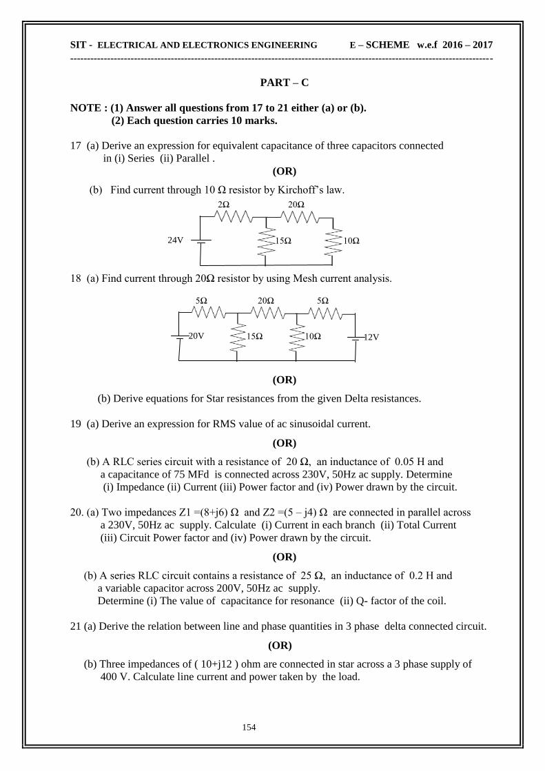
SIT - ELECTRICAL AND ELECTRONICS ENGINEERING E – SCHEME w.e.f 2016 – 2017
------------------------------------------------------------------------------------------------------------------------------
154
20Ω 2Ω
10Ω 15Ω 24V
5Ω 20Ω 5Ω
10Ω 15Ω 12V 20V
PART – C
NOTE : (1) Answer all questions from 17 to 21 either (a) or (b).
(2) Each question carries 10 marks.
17 (a) Derive an expression for equivalent capacitance of three capacitors connected
in (i) Series (ii) Parallel .
(OR)
(b) Find current through 10 Ω resistor by Kirchoff‘s law.
18 (a) Find current through 20Ω resistor by using Mesh current analysis.
(OR)
(b) Derive equations for Star resistances from the given Delta resistances.
19 (a) Derive an expression for RMS value of ac sinusoidal current.
(OR)
(b) A RLC series circuit with a resistance of 20 Ω, an inductance of 0.05 H and
a capacitance of 75 MFd is connected across 230V, 50Hz ac supply. Determine
(i) Impedance (ii) Current (iii) Power factor and (iv) Power drawn by the circuit.
20. (a) Two impedances Z1 =(8+j6) Ω and Z2 =(5 – j4) Ω are connected in parallel across
a 230V, 50Hz ac supply. Calculate (i) Current in each branch (ii) Total Current
(iii) Circuit Power factor and (iv) Power drawn by the circuit.
(OR)
(b) A series RLC circuit contains a resistance of 25 Ω, an inductance of 0.2 H and
a variable capacitor across 200V, 50Hz ac supply.
Determine (i) The value of capacitance for resonance (ii) Q- factor of the coil.
21 (a) Derive the relation between line and phase quantities in 3 phase delta connected circuit.
(OR)
(b) Three impedances of ( 10+j12 ) ohm are connected in star across a 3 phase supply of
400 V. Calculate line current and power taken by the load.

SIT - ELECTRICAL AND ELECTRONICS ENGINEERING E – SCHEME w.e.f 2016 – 2017
------------------------------------------------------------------------------------------------------------------------------
155
SESHASAYEE INSTITUTE OF TECHNOLOGY
ELECTRICAL AND ELECTRONICS ENGINEERING
MODEL QUESTION PAPER
Term : III Time : 3Hrs
Course: ELECTRICAL MACHINE - I Max.marks: 75
.
PART – A
NOTE : (1) 5 questions are to be answered out of 8 questions.
(2) Question No. 8 will be compulsory.
(3) Each question carries 2 marks.
01. Define MMF
02. Define critical field resistance of a d.c shunt generator.
03. What are the losses in a D.C machine?
04. State the applications of DC shunt motor.
05. Define voltage regulation of a transformer.
06. What is all day efficiency?
07. Mention the different connections of three phase distribution transformer.
08. What are the indications of fully charged cell?
PART – B
NOTE : (1) 5 questions are to be answered out of 8 questions.
(2) Question No. 16 will be compulsory.
(3) Each question carries 3 marks.
09. State Faraday‘s laws of electromagnetic induction.
10. What is the function of commutator?
11. What are the conditions for self excitation?
12. State the causes for voltage drop in d.c generators.
13. What is counter e.m.f in a d.c motor?
14. What is the need for starter in a DC motor?
15. Mention the use of breather.
16. State the applications of Alkaline cell.
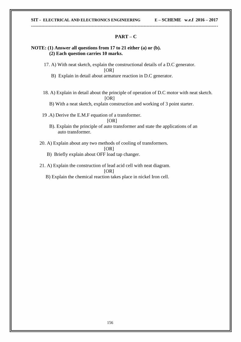
SIT - ELECTRICAL AND ELECTRONICS ENGINEERING E – SCHEME w.e.f 2016 – 2017
------------------------------------------------------------------------------------------------------------------------------
156
PART – C
NOTE: (1) Answer all questions from 17 to 21 either (a) or (b).
(2) Each question carries 10 marks.
17. A) With neat sketch, explain the constructional details of a D.C generator.
[OR]
B) Explain in detail about armature reaction in D.C generator.
18. A) Explain in detail about the principle of operation of D.C motor with neat sketch.
[OR]
B) With a neat sketch, explain construction and working of 3 point starter.
19 .A) Derive the E.M.F equation of a transformer.
[OR]
B). Explain the principle of auto transformer and state the applications of an
auto transformer.
20. A) Explain about any two methods of cooling of transformers.
[OR]
B) Briefly explain about OFF load tap changer.
21. A) Explain the construction of lead acid cell with neat diagram.
[OR]
B) Explain the chemical reaction takes place in nickel Iron cell.
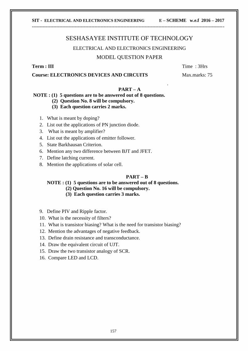
SIT - ELECTRICAL AND ELECTRONICS ENGINEERING E – SCHEME w.e.f 2016 – 2017
------------------------------------------------------------------------------------------------------------------------------
157
SESHASAYEE INSTITUTE OF TECHNOLOGY
ELECTRICAL AND ELECTRONICS ENGINEERING
MODEL QUESTION PAPER
Term : III Time : 3Hrs
Course: ELECTRONICS DEVICES AND CIRCUITS Max.marks: 75
.
PART – A
NOTE : (1) 5 questions are to be answered out of 8 questions.
(2) Question No. 8 will be compulsory.
(3) Each question carries 2 marks.
1. What is meant by doping?
2. List out the applications of PN junction diode.
3. What is meant by amplifier?
4. List out the applications of emitter follower.
5. State Barkhausan Criterion.
6. Mention any two difference between BJT and JFET.
7. Define latching current.
8. Mention the applications of solar cell.
PART – B
NOTE : (1) 5 questions are to be answered out of 8 questions.
(2) Question No. 16 will be compulsory.
(3) Each question carries 3 marks.
9. Define PIV and Ripple factor.
10. What is the necessity of filters?
11. What is transistor biasing? What is the need for transistor biasing?
12. Mention the advantages of negative feedback.
13. Define drain resistance and transconductance.
14. Draw the equivalent circuit of UJT.
15. Draw the two transistor analogy of SCR.
16. Compare LED and LCD.

SIT - ELECTRICAL AND ELECTRONICS ENGINEERING E – SCHEME w.e.f 2016 – 2017
------------------------------------------------------------------------------------------------------------------------------
158
PART – C
NOTE : (1) Answer all questions from 17 to 21 either (a) or (b).
(2) Each question carries 10 marks.
17. (A) (i) Explain the working of PN junction diode with neat sketch
(ii) Explain the zener diode as a voltage regulator.
[OR]
(B) Explain the working of bridge rectifier with relevant waveforms.
18. (A) Explain the operation and input and output characteristics of common emitter transistor
[OR]
(B) Draw the circuit, frequency response and explain the operation of RC coupled amplifier
19. (A) (i) With the diagram explain the operation of crystal oscillator.
(ii) Explain the characteristics of UJT with necessary diagram.
[OR]
(B) Explain the drain and transfer characteristics of JFET.
20. (A) Explain the construction and working of SCR with its characteristics.
[OR]
(B) Explain the operation of speed control of fan using DIAC and TRIAC.
21. (A) Explain briefly about LDR.
[OR]
(B) Explain the different types of clipper circuits

SIT - ELECTRICAL AND ELECTRONICS ENGINEERING E – SCHEME w.e.f 2016 – 2017
------------------------------------------------------------------------------------------------------------------------------
159
SESHASAYEE INSTITUTE OF TECHNOLOGY
ELECTRICAL AND ELECTRONICS ENGINEERING
MODEL QUESTION PAPER
Term : III Time : 3Hrs
Course: C++ Programming Max.marks: 75
.
PART – A
NOTE : (1) 5 questions are to be answered out of 8 questions.
(2) Question No. 8 will be compulsory.
(3) Each question carries 2 marks.
01) Give any two difference between procedure oriented and object oriented programming
02) What is meant by initialization of variables .
03) Give the general structure of if .. else statement.
04) Define friend functions with its rule.
05) Define inheritance.
06) What is stream what are stream classes.
07) Explain about command line arguments.
08) Write short notes on cout object.
PART – B
NOTE : (1) 5 questions are to be answered out of 8 questions.
(2) Question No. 16 will be compulsory.
(3) Each question carries 3 marks.
09) Write any four features of OOP.
10) Give the syntax of ‗do … while ‘ loop.
11) How will you define member function outside the class? Give Example
12) Define constructors and destructors
13) Give the general form for overloading unary operator and calling a overloaded function.
14) How pointers to derived classes are created.
15) What is the use of the function setprecision().
16) What is the purpose of the function write()

SIT - ELECTRICAL AND ELECTRONICS ENGINEERING E – SCHEME w.e.f 2016 – 2017
------------------------------------------------------------------------------------------------------------------------------
160
PART – C
NOTE : (1) Answer all questions from 17 to 21 either (a) or (b).
(2) Each question carries 10 marks.
17) A i) Write notes on a) keywords b) Logical operators.
ii) List down the applications of C++.
(or)
B i) Write a program to find the sum of even numbers from 0 to 100
ii) Give the syntax of ‗for‘ loop. Explain with an example.
18) A i) Write the syntax of a function. Briefly explain with an example.
ii) How memory is allocated for objects
(or)
B i) How arrays are used within a class
ii) With an example, Explain nesting of member functions.
19) A i) Write notes on copy constructors?
ii) Define operator overloading. Give the rules for overloading operators.
(or)
B) Explain with an example, how can you overload a casting operator to convert an
user defined data type to basic data type.
20) A Explain briefly the following with suitable example and diagrammatic
representation. i) single inheritance ii) multiple inheritance
(or)
B i) Give the rules for virtual functions.
ii) Explain the use of a ‗this‘ pointer with a simple program.
21) A Explain the different methods available to format the output data item.
(or)
B i) What are file pointers. Explain seekg() and tellp()
ii) Explain how will you open a file using constructor and function open().
***********

SIT - ELECTRICAL AND ELECTRONICS ENGINEERING E – SCHEME w.e.f 2016 – 2017
------------------------------------------------------------------------------------------------------------------------------
161
SESHASAYEE INSTITUTE OF TECHNOLOGY
ELECTRICAL AND ELECTRONICS ENGINEERING
MODEL QUESTION PAPER
Term : IV Time : 3Hrs
Course: ELECTRICAL MACHINE - II Max.marks: 75
.
PART – A
NOTE : (1) 5 questions are to be answered out of 8 questions.
(2) Question No. 8 will be compulsory.
(3) Each question carries 2 marks.
1. What are the two types of alternator?
2. Define pitch factor.
3. Define synchronous reactance.
4. Mention the methods used for synchronisation of alternator.
5. Define slip in induction motor.
6. What is meant by cogging in 3 phase induction motor?
7. Why single phase induction motor is not self starting?
8. Mention the different types of stepper motor.
PART – B
NOTE : (1) 5 questions are to be answered out of 8 questions.
(2) Question No. 16 will be compulsory.
(3) Each question carries 3 marks.
9. State the advantages of rotating field system in alternator.
10. What are the advantages of hydrogen cooling?
11. Write the reasons for voltage drop in alternator.
12. What are the conditions to be fulfilled for parallel operation of alternator?
13. Derive the relation between slip and slip frequency of three phase induction motor.
14. Compare squirrel cage and slip ring induction motor (any three points).
15. Name the methods of starting synchronous motor.
16. What is linear induction motor?

SIT - ELECTRICAL AND ELECTRONICS ENGINEERING E – SCHEME w.e.f 2016 – 2017
------------------------------------------------------------------------------------------------------------------------------
162
PART – C
NOTE : (1) Answer all questions from 17 to 21 either (a) or (b).
(2) Each question carries 10 marks.
17. A) Derive the E.M.F equation of an alternator.
[OR]
B) Explain the methods of obtaining sine wave in salient pole alternator
with neat sketch.
18. A) Explain the synchronous reactance method of predetermining the voltage
regulation of an alternator.
[OR]
B) Explain briefly the synchronizing of two three phase alternators by synchroscope
method.
19. A) Explain slip- torque characteristics of 3-phase induction motor.
[OR]
B) Explain with a neat diagram, the working of DOL starter.
20. A) Explain V curves and inverted V curves of the synchronous motor at constant
input power
[OR]
B) Explain the construction and working principle of split phase induction motor.
21. A) Explain the construction and working of permanent magnet synchronous motor.
[OR]
B) Explain the construction and working of variable reluctance stepper motor.

SIT - ELECTRICAL AND ELECTRONICS ENGINEERING E – SCHEME w.e.f 2016 – 2017
------------------------------------------------------------------------------------------------------------------------------
163
SESHASAYEE INSTITUTE OF TECHNOLOGY
ELECTRICAL AND ELECTRONICS ENGINEERING
MODEL QUESTION PAPER
Term : IV Time : 3Hrs
Course: ANALOG & DIGITAL ELECTRONICS Max.marks: 75
.
PART – A
NOTE : (1) 5 questions are to be answered out of 8 questions.
(2) Question No. 8 will be compulsory.
(3) Each question carries 2 marks.
01) What is open loop voltage gain?
02) What are the uses of IC 555.
03) Convert the decimal number 852.25 to its equivalent binary number.
04) What is half adder.
05) Define FAN-IN.
06) What is flipflop and also write the types of flipflop.
07) What is Ring counter.
08) Define ‗Conversion Time‘ in ADC.
PART – B
NOTE : (1) 5 questions are to be answered out of 8 questions.
(2) Question No. 16 will be compulsory.
(3) Each question carries 3 marks.
09) What are the four stages of OP-AMP.
10) Why is the NAND gate called universal logic gate.
11) Construct the logic diagram for the Boolean expression Y = AB + B‘C + A‘C.
12) What are the advantages of CMOS Gates.
13) Write notes on ‗Edge triggering in flipflops‘.
14) Write the applications of shift register.
15) Explain the operation of R-2R ladder DAC.
16) What are the features of IC regulator using LM317

SIT - ELECTRICAL AND ELECTRONICS ENGINEERING E – SCHEME w.e.f 2016 – 2017
------------------------------------------------------------------------------------------------------------------------------
164
PART – C
NOTE : (1) Answer all questions from 17 to 21 either (a) or (b).
(2) Each question carries 10 marks.
17) (A) Explain the the operation of OPAMP as inverting amplifier with diagram.
(or)
(B) Explain the operation astable multivibrator using 555 IC.
18) (A) State and prove the De-Morgan‘s theorems.
(or)
(B) Simplify the given functions by using K –map simulates its output
Y = ( 0,1,2,3,4,5,8,9,10,11,12)
19) (A) With neat sketch explain the operation of full subtractor.
(or)
(B) Draw and Explain the circuit diagram of TTL NAND gate.
20) (A) Explain with a neat sketch the operation of JKMS flip flop.
(or)
(B) Explain the operation of MOD 16 binary up counter.
21) (A) Explain the successive approximation method A/D converter.
(or)
(B) Explain Static RAM organisation with neat sketch.

SIT - ELECTRICAL AND ELECTRONICS ENGINEERING E – SCHEME w.e.f 2016 – 2017
------------------------------------------------------------------------------------------------------------------------------
165
SESHASAYEE INSTITUTE OF TECHNOLOGY
ELECTRICAL AND ELECTRONICS ENGINEERING
MODEL QUESTION PAPER
Term : IV Time : 3Hrs
Course: MEASUREMENTS & INSTRUMENTS Max.marks: 75
.
PART – A
NOTE : (1) 5 questions are to be answered out of 8 questions.
(2) Question No. 8 will be compulsory.
(3) Each question carries 2 marks.
01. Define true value.
02. Give an example of absolute instrument.
03. What is multiplier resistance?
04. Write the relation between power and energy
05. Write the uses of synchroscope.
06. Define transducer.
07. What is the use of LVDT?
08. What are the types of Recorders ?
PART – B
NOTE : (1) 5 questions are to be answered out of 8 questions.
(2) Question No. 16 will be compulsory.
(3) Each question carries 3 marks.
09. List the three types of operating forces.
10. Write any 3 application of CRO.
11. What are the types of power factor meter.
12. List the errors in induction type energy meter.
13. What are the uses of multimeter?
14. What is thermistor?
15. Write the name of the bridge circuit for inductance & capacitance
16. What is synchroscope?
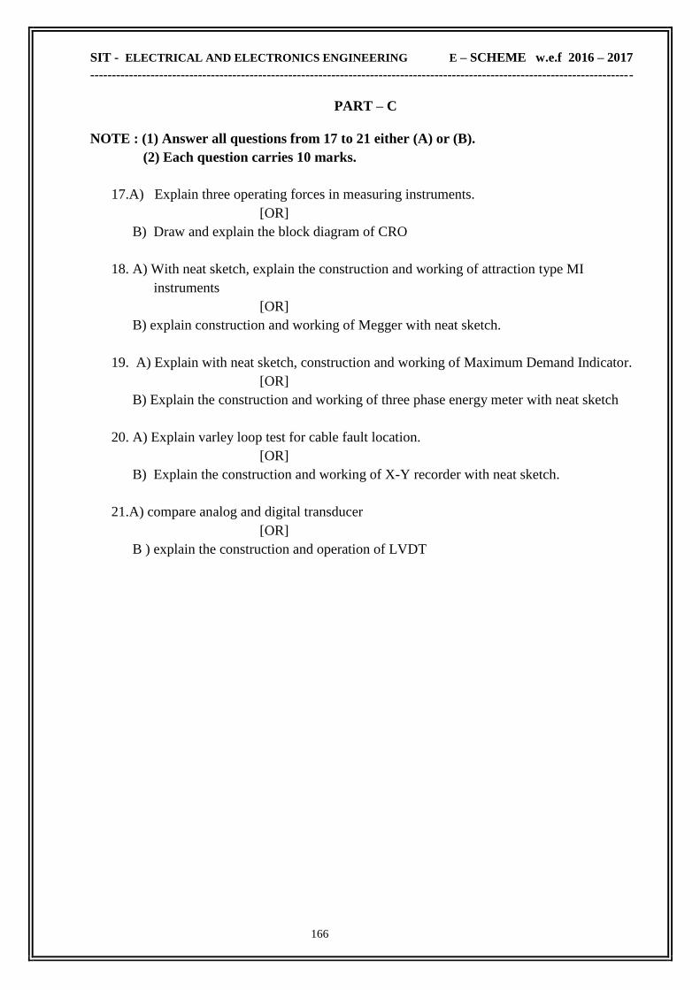
SIT - ELECTRICAL AND ELECTRONICS ENGINEERING E – SCHEME w.e.f 2016 – 2017
------------------------------------------------------------------------------------------------------------------------------
166
PART – C
NOTE : (1) Answer all questions from 17 to 21 either (A) or (B).
(2) Each question carries 10 marks.
17.A) Explain three operating forces in measuring instruments.
[OR]
B) Draw and explain the block diagram of CRO
18. A) With neat sketch, explain the construction and working of attraction type MI
instruments
[OR]
B) explain construction and working of Megger with neat sketch.
19. A) Explain with neat sketch, construction and working of Maximum Demand Indicator.
[OR]
B) Explain the construction and working of three phase energy meter with neat sketch
20. A) Explain varley loop test for cable fault location.
[OR]
B) Explain the construction and working of X-Y recorder with neat sketch.
21.A) compare analog and digital transducer
[OR]
B ) explain the construction and operation of LVDT
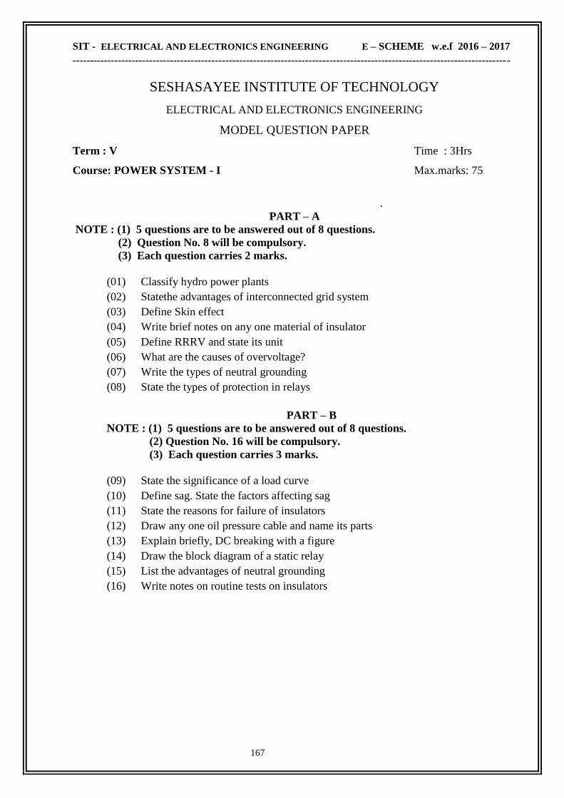
SIT - ELECTRICAL AND ELECTRONICS ENGINEERING E – SCHEME w.e.f 2016 – 2017
------------------------------------------------------------------------------------------------------------------------------
167
SESHASAYEE INSTITUTE OF TECHNOLOGY
ELECTRICAL AND ELECTRONICS ENGINEERING
MODEL QUESTION PAPER
Term : V Time : 3Hrs
Course: POWER SYSTEM - I Max.marks: 75
.
PART – A
NOTE : (1) 5 questions are to be answered out of 8 questions.
(2) Question No. 8 will be compulsory.
(3) Each question carries 2 marks.
(01) Classify hydro power plants
(02) Statethe advantages of interconnected grid system
(03) Define Skin effect
(04) Write brief notes on any one material of insulator
(05) Define RRRV and state its unit
(06) What are the causes of overvoltage?
(07) Write the types of neutral grounding
(08) State the types of protection in relays
PART – B
NOTE : (1) 5 questions are to be answered out of 8 questions.
(2) Question No. 16 will be compulsory.
(3) Each question carries 3 marks.
(09) State the significance of a load curve
(10) Define sag. State the factors affecting sag
(11) State the reasons for failure of insulators
(12) Draw any one oil pressure cable and name its parts
(13) Explain briefly, DC breaking with a figure
(14) Draw the block diagram of a static relay
(15) List the advantages of neutral grounding
(16) Write notes on routine tests on insulators

SIT - ELECTRICAL AND ELECTRONICS ENGINEERING E – SCHEME w.e.f 2016 – 2017
------------------------------------------------------------------------------------------------------------------------------
168
PART – C
NOTE : (1) Answer all questions from 17 to 21 either (a) or (b).
(2) Each question carries 10 marks.
17. a) Explain nuclear power plant with its schematic
[OR]
b) State and explain the types of tariff
18 .a) With neat diagram, explain the typical ac power supply scheme
[OR]
b) Draw and explain different DC links used in HVDC transmission system
19. a) Explain various types of line insulators
[OR]
b) Explain the construction of UG cable with a neat sketch
20. a) With neat sketch, explain the construction and working of SF6 Circuit breaker
[OR]
b) Explain low voltage HRC fuse with a sketch
21 .a) Explain the construction and working of induction type, non-directional over
current relay
[OR]
b )Explain Peterson coil earthing with a neat sketch and vector diagram

SIT - ELECTRICAL AND ELECTRONICS ENGINEERING E – SCHEME w.e.f 2016 – 2017
------------------------------------------------------------------------------------------------------------------------------
169
SESHASAYEE INSTITUTE OF TECHNOLOGY
ELECTRICAL AND ELECTRONICS ENGINEERING
MODEL QUESTION PAPER
Term : V Time : 3Hrs
Course: CONTROL& MAINTENANCE OF ELECTRICAL MACHINES Max.marks: 75
.
PART – A
NOTE : (1) 5 questions are to be answered out of 8 questions.
(2) Question No. 8 will be compulsory.
(3) Each question carries 2 marks.
1. Write the two types of push button switches.
2. Write the uses of proximity switch.
3. Define current limit acceleration.
4. Define dynamic breaking.
5. State the use of skip hoist.
6. Name any two trouble spot in a control circuit.
7. What is meant by degreasing?
8. Mention the causes for the noise in transformer.
PART – B
NOTE : (1) 5 questions are to be answered out of 8 questions.
(2) Question No. 16 will be compulsory.
(3) Each question carries 3 marks.
9. Explain a drum type switch.
10. What is a Latching relay?
11. Explain field failure protection.
12. What are the precautions to be taken while reversing a DC motor?
13. Explain the current speed characteristics of an AC motor during acceleration.
14. Explain plug stop and plug reversal.
15. How variation of temperature is achieved in electric oven?
16. State the quality of good transformer oil.

SIT - ELECTRICAL AND ELECTRONICS ENGINEERING E – SCHEME w.e.f 2016 – 2017
------------------------------------------------------------------------------------------------------------------------------
170
PART – C
NOTE : (1) Answer all questions from 17 to 21 either (a) or (b).
(2) Each question carries 10 marks.
17. (A) Draw the control circuit of electrical interlock and mechanical interlock and explain.
[OR]
(B) Discuss the principle of operation of pneumatic timer.
18. (A) State and explain the closed circuit transition in autotransformer starter for induction
motor.
[OR]
(B) Draw the control circuit for automatic rotor resistance starter for 3Ф induction motor
and explain.
19. (A) Explain the control circuit of skip hoist with neat sketch.
[OR]
(B) Explain air compressor and its control circuit.
20. (A) Explain the methods of drying out process carried out in case of induction motor.
[OR]
(B) Explain briefly the steps taken in order to maintain the bearing of an induction motor.
21. (A) Write a note on short circuit and mechanical forces on transformer.
[OR]
(B) What are the precautions needed for paralleling of two transformers?

SIT - ELECTRICAL AND ELECTRONICS ENGINEERING E – SCHEME w.e.f 2016 – 2017
------------------------------------------------------------------------------------------------------------------------------
171
SESHASAYEE INSTITUTE OF TECHNOLOGY
ELECTRICAL AND ELECTRONICS ENGINEERING
MODEL QUESTION PAPER
Term : V Time : 3Hrs
Course: MICRO CONTROLLER Max.marks: 75
.
PART – A
NOTE : (1) 5 questions are to be answered out of 8 questions.
(2) Question No. 8 will be compulsory.
(3) Each question carries 2 marks.
01) What is the purpose of register ACCUMULATOR
02) What are the flags used in 8051 and 8085.
03) Explain the logical AND operation of 8051.
04) What is the purpose of the instruction ―MOV A,@R1‖
05) What is the difference between the flags CY and OV.
06) What is interrupt signal.
07) Mention the ports placed in 8255.
08) What is the purpose of the instruction ―JNZ‖
PART – B
NOTE : (1) 5 questions are to be answered out of 8 questions.
(2) Question No. 16 will be compulsory.
(3) Each question carries 3 marks.
09) State any three differences between microprocessor and microcontroller.
10) Give the format of PSW in 8051.
11) Explain direct addressing mode with examples.
12) Explain the instruction ― MUL AB ‖ in 8051 with suitable example.
13) How will you start and stop the timer/counter.
14) Give the format of IE register in 8051.
15) Name the six different modes of external timers.
16) Explain the purpose of the instruction ‗MOVX‘ IN 8051.

SIT - ELECTRICAL AND ELECTRONICS ENGINEERING E – SCHEME w.e.f 2016 – 2017
------------------------------------------------------------------------------------------------------------------------------
172
PART – C
NOTE : (1) Answer all questions from 17 to 21 either (a) or (b).
(2) Each question carries 10 marks.
17) (A) Draw and Explain the Architecture of 8051.
(or)
(B) (i) Draw the pin diagram of microcontroller 8051.
(ii) List down any 10 SFRs with their byte and bit addresses.
18) (A) Explain how to assemble and run an 8051 program using assembler .
(or)
(B) Explain the instructions ―CJNE & DJNZ‖ with example .
19) (A) Explain mode 1 and mode 2 operation of timer.
(or)
(B) Write an assembly language program to generate a square wave
of 2 KHz on port pin 1.0 using timer 0 mode 2. Assume crystal frequency
to be 11.0592 MHz.
20) (A) Write the steps to transfer character bytes serially in 8051.
(or)
(B) Write the format of SCON and PCON registers and explain.
21) (A) Explain LCD display interfacing with 8051.
(or)
(B) Explain DC motor interfacing with 8051.

SIT - ELECTRICAL AND ELECTRONICS ENGINEERING E – SCHEME w.e.f 2016 – 2017
------------------------------------------------------------------------------------------------------------------------------
173
SESHASAYEE INSTITUTE OF TECHNOLOGY
ELECTRICAL AND ELECTRONICS ENGINEERING
MODEL QUESTION PAPER
Term : V Time : 3Hrs
Course: VLSI Max.marks: 75
.
PART – A
NOTE : (1) 5 questions are to be answered out of 8 questions.
(2) Question No. 8 will be compulsory.
(3) Each question carries 2 marks.
1. What is CMOS ?
2. List few combinational circuit.
3.What is simulation.
4. Write VHDL code for OR gate.
5. Define sequential circuit.
6. Write different modes of shift register.
7. Define state diagram.
8. Write major parts in FPGA.
PART – B
NOTE : (1) 5 questions are to be answered out of 8 questions.
(2) Question No. 16 will be compulsory.
(3) Each question carries 3 marks.
9. Write short notes on Hazards?
10. Relate variable and function .
11.Wtite different level of obstraction in VHDL
12.Write VHDL code for 4x1 multiplexer.
13. Difference between Latch and flip -flop.
14. Define moore & mealy machine.
15.Write VHDL code for D latch.
16.What is the difference between PLA & PAL ?

SIT - ELECTRICAL AND ELECTRONICS ENGINEERING E – SCHEME w.e.f 2016 – 2017
------------------------------------------------------------------------------------------------------------------------------
174
PART – C
NOTE : (1) Answer all questions from 17 to 21 either (a) or (b).
(2) Each question carries 10 marks.
17. (A) With necessary diagrams explain the working of NOT, AND and OR plane
using CMOS.
OR
(B) Implement the function F=∑m (0,2,3,7,12,14,15)
Implement the above function with a 4 to 1 multiplexer.
18. (A) Write VHDL code for decoder and single bit comparator.
OR
(B) Write VHDL code for 4 bit adder.
19. (A) Write and explain excitation table of RS and D flip-flop .
OR
(B) Design modulo 5 counter using D flip-flop.
20. (A) Write VHDL code for JK and D flip-flop with reset input.
OR
(B) Write VHDL code for 4 bit up counter.
21. (A) What is PLA? How do you realize the given function with a PLA .
F1 (x,y,z) = ∑m (0,1,3,4)
F2 (x,y,z ) = ∑m (1,2,3,4,5)
OR
(B) With a block diagram, explain the working of CPLD.

SIT - ELECTRICAL AND ELECTRONICS ENGINEERING E – SCHEME w.e.f 2016 – 2017
------------------------------------------------------------------------------------------------------------------------------
175
SESHASAYEE INSTITUTE OF TECHNOLOGY
ELECTRICAL AND ELECTRONICS ENGINEERING
MODEL QUESTION PAPER
Term : III Time : 3Hrs
Course: ELECTRICAL MACHINE DESIGN Max.marks: 75
.
PART – A
NOTE : (1) 5 questions are to be answered out of 8 questions.
(2) Question No. 8 will be compulsory.
(3) Each question carries 2 marks.
1. What are the main dimensions of a rotating machine?
2. Name a few insulating materials that are used in transformers.
3. What is magnetic circuit and what are its constituents?
4. Define specific magnetic loading.
5. What is tertiary winding?
6. What are the types of windings commonly used for LV winding?
7. What are the factors that decide the choice of specific electric loading?
8. What is run-away speed?
PART – B
NOTE : (1) 5 questions are to be answered out of 8 questions.
(2) Question No. 16 will be compulsory.
(3) Each question carries 3 marks.
9. What are the factors that affect the size of rotating machines?
10. What are the important properties of steel used in transformer core?
11. What is magnetic leakage and leakage coefficient?
12. What is magnetization curve?
13. What are the advantages and disadvantages of stepped cores?
14. List the different methods of cooling of transformers.
15. What is Carter‘s coefficient? What is its usefulness in the design of DC machines?
16. List out the methods to improve the power factor of an induction motor.

SIT - ELECTRICAL AND ELECTRONICS ENGINEERING E – SCHEME w.e.f 2016 – 2017
------------------------------------------------------------------------------------------------------------------------------
176
PART – C
NOTE : (1) Answer all questions from 17 to 21 either (a) or (b).
(2) Each question carries 10 marks.
17. (A) Discuss about the various types of thermal ratings of the electrical machines.
[OR]
(B) Discuss about the various insulating materials and their grades.
18. (A) Explain in detail about the MMF calculation for tapered teeth.
[OR]
(B) Discuss in detail about the real and apparent flux densities.
19. (A) Derive the voltage per turn equation of a transformer.
[OR]
(B) Calculate the dimensions of the core, the number of turns and cross sectional area of
conductors in the primary and secondary windings of a 100 KVA, 2200/480 V, 50 Hz,
single phase core type transformer by assuming the following data. Approximate volt per
turn = 7.5 volt, Maximum flux density = 1.2T, ratio of effective cross sectional area of
core to square of diameter of circumscribing circle is 0.6, ratio of height to width of
window is 2, window space factor = 0.28, current density = 2.5 A/mm2 .
20. (A) Derive the output equation of a DC machine.
[OR]
(B) Design a suitable commutator for a 350 KW, 600 rpm, 440 V, 6 poles DC generator
having an armature diameter of 0.75m. The number of slots is 288. Assume suitable
values where its necessary?
21. (A) A 90 KW, 500 V, 50Hz, three phase, 8 pole induction motor has a star connected stator
winding accommodated in 63 slots with a 6 conductors/slot. If slip ring voltage in open
circuit is to be about 400V at no load, find the suitable rotor winding. Calculate number of
rotor slots, number of conductors/slot, coil span, number of slots per pole. P.F = 0.9 and the
efficiency is 0.85.
[OR]
(B) Explain in detail about the cooling of turbo alternators.

SIT - ELECTRICAL AND ELECTRONICS ENGINEERING E – SCHEME w.e.f 2016 – 2017
------------------------------------------------------------------------------------------------------------------------------
177
SESHASAYEE INSTITUTE OF TECHNOLOGY
ELECTRICAL AND ELECTRONICS ENGINEERING
MODEL QUESTION PAPER
Term : VI Time : 3Hrs
Course: POWER SYSTEM - II Max.marks: 75
.
PART – A
NOTE : (1) 5 questions are to be answered out of 8 questions.
(2) Question No. 8 will be compulsory.
(3) Each question carries 2 marks.
01. What is aFeeder?
02. Give two advantages of electric drives
03. What are the types of bearings?
04. Define Schedule speed
05. State the causes of end blackening of a fluorescent lamp
06. Define luminous efficiency
07. What are the modes of heat transfer?
08. Write any two differences between resistance & arc welding
PART – B
NOTE : (1) 5 questions are to be answered out of 8 questions.
(2) Question No. 16 will be compulsory.
(3) Each question carries 3 marks.
09. Draw single busbar system
10. Write notes on types of enclosures
11. Draw Metadyne control arrangement for speed control of traction motor
12. Define specific energy consumption and state the factors affecting it.
13. What are the advantages of electric traction?
14. What is stroboscopic effect? How it can be eliminated?
15. Write notes on welding equipments
16. What are the types of substations?

SIT - ELECTRICAL AND ELECTRONICS ENGINEERING E – SCHEME w.e.f 2016 – 2017
------------------------------------------------------------------------------------------------------------------------------
178
PART – C
NOTE : (1) Answer all questions from 17 to 21 either (a) or (b).
(2) Each question carries 10 marks.
17. a) Explain the equipments used in substations
[OR]
b) Draw and explain radial, ring main & interconnected systems of distribution
18. a) With neat sketches, explain the types of electric drives
[OR]
b) Suggest suitable motors for the following applications. Give reasons for your choice
i) Textile mill, ii) Cranes, iii) Centrifugal pumps, iv) Paper mill, v) Vacuum cleaner
19. a) Explain different methods of supplying power to traction system
[OR]
b) Draw and explain speed time curve of traction motor
20. a) With neat sketch, explain any one law of illumination with its statement.
[OR]
b) Explain various lighting schemes
21. a) Explain construction and working of Ajax Wyatt vertical core furnace with neat sketch
[OR]
b )Explain Electron beam welding with a neat sketch
***********

SIT - ELECTRICAL AND ELECTRONICS ENGINEERING E – SCHEME w.e.f 2016 – 2017
------------------------------------------------------------------------------------------------------------------------------
179
SESHASAYEE INSTITUTE OF TECHNOLOGY
ELECTRICAL AND ELECTRONICS ENGINEERING
MODEL QUESTION PAPER
Term : VI Time : 3Hrs
Course: POWER ELECTRONICS Max.marks: 75
.
PART – A
NOTE : (1) 5 questions are to be answered out of 8 questions.
(2) Question No. 8 will be compulsory.
(3) Each question carries 2 marks.
1. Give the symbol for the following devices (i) IGBT (ii) SCS
2. What is commutation?
3. State the purpose of free wheeling diode.
4. Mention the types of inverters.
5. Write the applications of chopper.
6. What is the meaning of asymmetrical firing?
7. What is the cuk converter?
8. What is a cyclo converter?
PART – B
NOTE : (1) 5 questions are to be answered out of 8 questions.
(2) Question No. 16 will be compulsory.
(3) Each question carries 3 marks.
9. Explain the following terms. (i) Latching current (ii) Holding current
10. State the requirements of gate triggering circuit
11. Write the expression for average DC output voltage of single phase fully controlled
bridge rectifier with RL load.
12. Mention the sources of voltage transients.
13. Draw and explain operating region of armature voltage control and field current control.
14. Draw and explain the block diagram of separately excited DC motor speed control.
15. List the various methods available for AC motor speed control.
16. What are the advantages of AC drive?

SIT - ELECTRICAL AND ELECTRONICS ENGINEERING E – SCHEME w.e.f 2016 – 2017
------------------------------------------------------------------------------------------------------------------------------
180
PART – C
NOTE : (1) Answer all questions from 17 to 21 either (a) or (b).
(2) Each question carries 10 marks.
17. (a) Explain Class – B and Class – D commutation with a circuit diagram.
[OR]
(b) With neat diagram explain the operation of synchronized UJT triggering
18. (a) Explain the principle of operation of single phase fully controlled bridge converter having
RL load with associated waveforms.
[OR]
(b) With relevant waveforms discuss the working principle of a three phase half controlled
bridge converter with R-L load in continuous mode.
19. (a) Explain the operation of three phase bridge inverter under 1200 mode.
[OR]
(b) Explain the operation of Buck – Boost converter.
20. (a) With suitable block diagram explain online UPS.
[OR]
(b) Explain separately excited DC motor speed control with single phase full converter drive.
21. (a) Explain with circuit diagram the slip power recovery scheme.
[OR]
(b) Explain variable voltage and frequency control using inverter.

SIT - ELECTRICAL AND ELECTRONICS ENGINEERING E – SCHEME w.e.f 2016 – 2017
------------------------------------------------------------------------------------------------------------------------------
181
SESHASAYEE INSTITUTE OF TECHNOLOGY
ELECTRICAL AND ELECTRONICS ENGINEERING
MODEL QUESTION PAPER
Term : VI Time : 3Hrs
Course: RENEWABLE ENERGY SOURCES & ENERGY AUDITING Max.marks: 75
.
PART – A
NOTE : (1) 5 questions are to be answered out of 8 questions.
(2) Question No. 8 will be compulsory.
(3) Each question carries 2 marks.
01. Define energy yield ratio
02. State any two advantages of fuel cells
03. Define solar constant
04. List the system components in on grid solar power plant
05. State the factors determining the output from a wind energy
06. List the categories of biomass resources
07. State the important parts of a wind mill
08. State any 4 roles of an energy manager
PART – B
NOTE : (1) 5 questions are to be answered out of 8 questions.
(2) Question No. 16 will be compulsory.
(3) Each question carries 3 marks.
09. Write brief notes on thermionic converter
10. Draw velocity duration curve & explain
11. State the phases of liquefaction
12. Write notes on fermentation
13. State the types of wave machine converters
14. Explain Energy Conservation Measures in Distribution
15. Compare three types of energy audit
16. Give examples for agricultural & organic wastes

SIT - ELECTRICAL AND ELECTRONICS ENGINEERING E – SCHEME w.e.f 2016 – 2017
------------------------------------------------------------------------------------------------------------------------------
182
PART – C
NOTE : (1) Answer all questions from 17 to 21 either (a) or (b).
(2) Each question carries 10 marks.
17. a) Explain the conclusions of the study on alternate energy strategies
[OR]
b) Explain thermo electric power generation with a sketch
18. a) Draw & explain the construction and working of Angstrom compensation
Pyrheliometer
[OR]
b) Explain the basic PV system for power generation with a block diagram
19. a) Explain the basic components of a WECS with a block diagram
[OR]
b) Explain the construction and working of floating gas holder digester with a sketch
20. a) Draw & explain double basin type tidal power plant
[OR]
b) B)Explain about the material selection for geothermal power plants
21.a) What is comprehensive energy audit? State the steps involved in it
[OR]
b) Explain various energy conservation measures for industries
****************
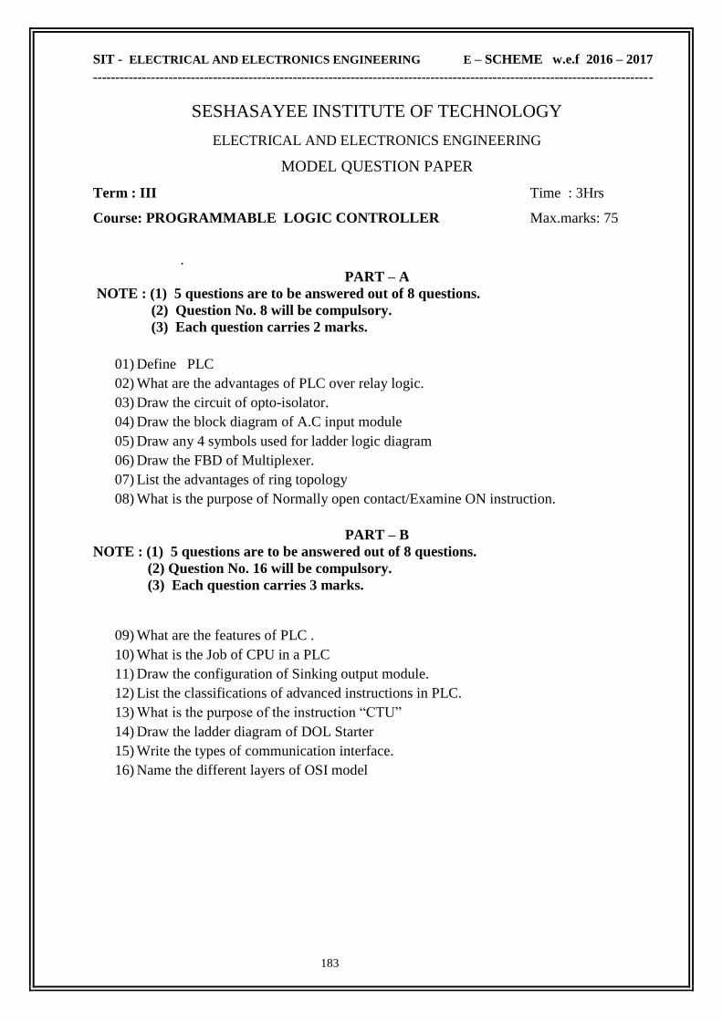
SIT - ELECTRICAL AND ELECTRONICS ENGINEERING E – SCHEME w.e.f 2016 – 2017
------------------------------------------------------------------------------------------------------------------------------
183
SESHASAYEE INSTITUTE OF TECHNOLOGY
ELECTRICAL AND ELECTRONICS ENGINEERING
MODEL QUESTION PAPER
Term : III Time : 3Hrs
Course: PROGRAMMABLE LOGIC CONTROLLER Max.marks: 75
.
PART – A
NOTE : (1) 5 questions are to be answered out of 8 questions.
(2) Question No. 8 will be compulsory.
(3) Each question carries 2 marks.
01) Define PLC
02) What are the advantages of PLC over relay logic.
03) Draw the circuit of opto-isolator.
04) Draw the block diagram of A.C input module
05) Draw any 4 symbols used for ladder logic diagram
06) Draw the FBD of Multiplexer.
07) List the advantages of ring topology
08) What is the purpose of Normally open contact/Examine ON instruction.
PART – B
NOTE : (1) 5 questions are to be answered out of 8 questions.
(2) Question No. 16 will be compulsory.
(3) Each question carries 3 marks.
09) What are the features of PLC .
10) What is the Job of CPU in a PLC
11) Draw the configuration of Sinking output module.
12) List the classifications of advanced instructions in PLC.
13) What is the purpose of the instruction ―CTU‖
14) Draw the ladder diagram of DOL Starter
15) Write the types of communication interface.
16) Name the different layers of OSI model

SIT - ELECTRICAL AND ELECTRONICS ENGINEERING E – SCHEME w.e.f 2016 – 2017
------------------------------------------------------------------------------------------------------------------------------
184
PART – C
NOTE : (1) Answer all questions from 17 to 21 either (a) or (b).
(2) Each question carries 10 marks.
17) A) Draw and Explain the block diagram of PLC system.
OR
B) i) List down and explain the various types of programming a PLC.
ii) Explain about the additional capabilities of PLC
18 ) A) Explain the function of ―INPUT Modules‖ with neat diagram.
OR
B) i) Briefly Explain the function of ―limit Switch‖ with neat diagram.
ii) Compare solid state output with Relay output.
19) A) i) Explain the following instruction : i) Output latch ii) ON delay Timer
ii) Draw the FBD for logic operation AND,OR,NOT
OR
B) Design ladder logic diagram to implement Demorgan‘s theorem.
20) A) List down the various mathematical instructions used in PLC and explain each briefly.
OR
B) Develop ladder logic diagram for jogging control circuit and explain the rung in the
ladder diagram.
21) A) i) Draw and Explain about the star topology.
ii) List the advantages and disadvantages of bus topology
OR
B) Draw and Explain the architecture of SCADA

SIT - ELECTRICAL AND ELECTRONICS ENGINEERING E – SCHEME w.e.f 2016 – 2017
------------------------------------------------------------------------------------------------------------------------------
185
SESHASAYEE INSTITUTE OF TECHNOLOGY
ELECTRICAL AND ELECTRONICS ENGINEERING
MODEL QUESTION PAPER
Term : VI Time : 3Hrs
Course: BIOMEDICAL INSTRUMENTATION Max.marks: 75
.
PART – A
NOTE : (1) 5 questions are to be answered out of 8 questions.
(2) Question No. 8 will be compulsory.
(3) Each question carries 2 marks
1. What is half cell potential?
2. What is photometry?
3. How the heart rate is controlled?
4. What is meant by speech audiometer?
5. What is meant by demand pacemaker?
6. What is meant by endoscopy?
7. What are the uses of Biotelemetry?
8. What is meant by tomogram?
PART – B
NOTE : (1) 5 questions are to be answered out of 8 questions.
(2) Question No. 16 will be compulsory.
(3) Each question carries 3 marks.
9. Mention the transducers used in medical field.
10. What is meant by resting and action potential?
11. Draw and explain Einthoven triangle.
12. List the different types of audiometer.
13. Bring out the comparison between external and internal pacemakers.
14. Write short notes on ventilators.
15. Draw the block diagram of components of biotelemetry system.
16. List the applications of LASER in medicine.

SIT - ELECTRICAL AND ELECTRONICS ENGINEERING E – SCHEME w.e.f 2016 – 2017
------------------------------------------------------------------------------------------------------------------------------
186
PART – C
NOTE : (1) Answer all questions from 17 to 21 either (a) or (b).
(2) Each question carries 10 marks.
17. (A) Give the details of polarized & unpolarized cell during resting & action potential
[OR]
(B) Draw and explain the working of electromagnetic blood flow meter
18. (A) Explain the different lead configurations used in ECG
[OR]
(B) Draw the schematic diagram of Beksey audiometer and explain its working principle
19. (A) Draw and explain the different types of defibrillators.
[OR]
(B) Write short notes on short wave diathermy and microwave diathermy.
20. (A) (i) Draw the block diagram of biotelemetry system and explain each block
(ii) What are the problems in implant telemetry?
[OR]
(B) (i) What are the physiological effect due to 50Hz current passage?
(ii)What are the cause for leakage current?
21. (A) Draw and explain the block diagram of an X- ray machine
[OR]
(B) Explain the ultrasonic B-mode &T-M mode display of echoes

SIT - ELECTRICAL AND ELECTRONICS ENGINEERING E – SCHEME w.e.f 2016 – 2017
------------------------------------------------------------------------------------------------------------------------------
187
SESHASAYEE INSTITUTE OF TECHNOLOGY
ELECTRICAL AND ELECTRONICS ENGINEERING
MODEL QUESTION PAPER
Term : VI Time : 3Hrs
Course: COMPUTER HARDWARE NETWORKING Max.marks: 75
.
PART – A
NOTE : (1) 5 questions are to be answered out of 8 questions.
(2) Question No. 8 will be compulsory.
(3) Each question carries 2 marks.
1. What are the different types of cabling supported by Ethernet standard?
2. List the 2 advantages of networking
3. What is NIC?
4. Define broadband.
5. List 2 drawbacks of ring topology
6. What is the responsibility of network layer?
7. Define FTP
8. What is SLIP?
PART – B
NOTE : (1) 5 questions are to be answered out of 8 questions.
(2) Question No. 16 will be compulsory.
(3) Each question carries 3 marks.
9. What are the different types of data flow?
10. What are the characteristic of network transmission media?
11. What is protocol?
12. What is flow control?
13. What are the different types of error?
14. What is ICMP?
15 .Define POP
16. Define URL, Give suitable example.
\

SIT - ELECTRICAL AND ELECTRONICS ENGINEERING E – SCHEME w.e.f 2016 – 2017
------------------------------------------------------------------------------------------------------------------------------
188
PART – C
NOTE : (1) Answer all questions from 17 to 21 either (a) or (b).
(2) Each question carries 10 marks.
17. a) Explain Different data flow methods.
(or)
b) Explain BUS & STAR topology with diagram mentions its merits & Demerits.
18. a) Explain the TCP/IP protocol suite in details.
(or)
b) Explain the Network Layer protocol.
19. a) Explain the error correction & Detection methods.
(or)
b) Explain Digital transmission modes.
20. a) Explain about RARP & IGMP protocols.
(or)
b) Explain OSI Model
21. (a) Explain about FTP & IMAP protocols & its functions
(or)
(b) Explain about DNS in details

SIT - ELECTRICAL AND ELECTRONICS ENGINEERING E – SCHEME w.e.f 2016 – 2017
------------------------------------------------------------------------------------------------------------------------------
189
Equivalent Papers
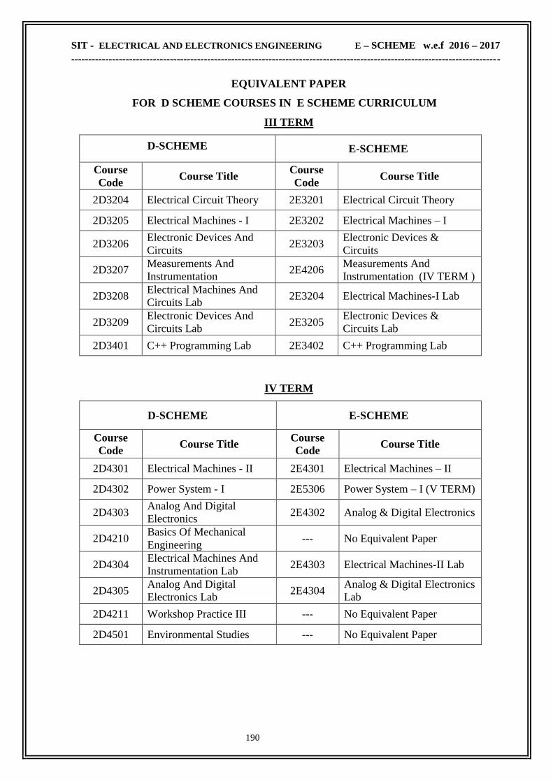
SIT - ELECTRICAL AND ELECTRONICS ENGINEERING E – SCHEME w.e.f 2016 – 2017
------------------------------------------------------------------------------------------------------------------------------
190
EQUIVALENT PAPER
FOR D SCHEME COURSES IN E SCHEME CURRICULUM
III TERM
D-SCHEME E-SCHEME
Course
Code Course Title
Course
Code Course Title
2D3204 Electrical Circuit Theory 2E3201 Electrical Circuit Theory
2D3205 Electrical Machines - I 2E3202 Electrical Machines – I
2D3206 Electronic Devices And
Circuits 2E3203
Electronic Devices &
Circuits
2D3207 Measurements And
Instrumentation 2E4206
Measurements And
Instrumentation (IV TERM )
2D3208 Electrical Machines And
Circuits Lab 2E3204 Electrical Machines-I Lab
2D3209 Electronic Devices And
Circuits Lab 2E3205
Electronic Devices &
Circuits Lab
2D3401 C++ Programming Lab 2E3402 C++ Programming Lab
IV TERM
D-SCHEME E-SCHEME
Course
Code Course Title
Course
Code Course Title
2D4301 Electrical Machines - II 2E4301 Electrical Machines – II
2D4302 Power System - I 2E5306 Power System – I (V TERM)
2D4303 Analog And Digital
Electronics 2E4302 Analog & Digital Electronics
2D4210 Basics Of Mechanical
Engineering --- No Equivalent Paper
2D4304 Electrical Machines And
Instrumentation Lab 2E4303 Electrical Machines-II Lab
2D4305 Analog And Digital
Electronics Lab 2E4304
Analog & Digital Electronics
Lab
2D4211 Workshop Practice III --- No Equivalent Paper
2D4501 Environmental Studies --- No Equivalent Paper

SIT - ELECTRICAL AND ELECTRONICS ENGINEERING E – SCHEME w.e.f 2016 – 2017
------------------------------------------------------------------------------------------------------------------------------
191
V TERM
D-SCHEME E-SCHEME
Course
Code Course Title Course Code Course Title
2D5306 Power System – II 2E6310 Power System – II
(VI TERM)
2D5307 Control of Electrical
Machines 2E5307
Control & Maintenance of
Electrical Machines
2D5308 Wiring, Winding &
Estimation Lab 2E5309
Wiring, Winding &
Estimation Lab
2D5402.1 Microcontroller 2E5403.1 Microcontroller
2D5402.2 Computer Hardware &
Networking 2E6406.3
Computer Hardware &
Networking (VI TERM)
2D5402.3 VLSI Design 2E5403.2 VLSI Design
2D5309 Control of Electrical
Machines Lab 2E5308
Control & Maintenance of
Electrical Machines Lab
2D5404 English Communication
Skills 2E4207
Life &Employability skill
Practical (IV TERM)
2D5403.1 Microcontroller Lab 2E5404.1 Microcontroller Lab
2D5403.2 Computer Hardware &
Networking Lab 2E6407.3
Computer Hardware &
Networking Lab (VI TERM)
2D5403.3 VLSI Design Lab 2E5404.2 VLSI Design Lab
2D5502 Disaster Management --- No Equivalent Paper

SIT - ELECTRICAL AND ELECTRONICS ENGINEERING E – SCHEME w.e.f 2016 – 2017
------------------------------------------------------------------------------------------------------------------------------
192
VI TERM
D-SCHEME E-SCHEME
Course
Code Course Title
Course
Code Course Title
2D6310 Programmable Logic
Controller 2E6406.1
Programmable Logic
Controller
2D6311 Power Electronics 2E6311 Power Electronics
2D6405.1 Renewable Energy Sources
& Energy Auditing 2E6312
Renewable Energy Sources &
Energy Auditing
2D6405.2 Special Electrical Machines --- No Equivalent Paper
2D6405.3 Bio-Medical Instrumentation 2E6406.2 Bio-Medical Instrumentation
2D6312 Programmable Logic
Controller Lab 2E6407.1
Programmable Logic
Controller Lab
2D6313 Power Electronics Lab 2E6313 Power Electronics Lab
2D6314 CAD & Simulation Lab 2E5405 CAD & Simulation Lab (V
TERM)
2D6406 Project Work 2E6408 Project Work
2D6503 Entrepreneurship --- No Equivalent Paper