Embed Size (px)
Citation preview
,!
..-
,.
I-. ,
I
I
.
)
‘\
)
NONMEASUREMENT’SENSITIVE
MIL-STD-1543B (USAF’)25OCI’88
SUPERSEDINGMIbsTD-1543A SAF)Dated 25 JUN 198r
MILITARY STANDARD
RELIABILITY PROGRAM
REQUIREMENTS
FOR
SPACE AND LAUNCH VEHICLES
,)AMSC F’4542 FSC REM
ISTRIBUTIO N STATEMENT& ● Approvedforpublicrelease;distributionunlimited.
I
MIL-STD-1543B (USAF)25 OCT 1988
)50.4
T- lo~ REVI~ - ●
a.
b.
c.
d.
~: Not applicable unless hardware,such as an experiment, is to be fabricated as partof the contract.
~: To impose a formal failure reportingand corrective action system (FRACAS) to varyingdegrees depending on the expected volume offailures for the particular program and thecriticality of major system components. If areliability development test is imposed, thegreatest benefit can be derived from failuresencountered during that testing program throughthe use of a FRACAS.
~: To obtain maximum benefit fromcorrection of failures encountered during anyformal qualification or acceptance testing.Contractor procedures may be used prior to formalqualification or acceptance testing.
~: To obtain maximum benefit fromcorrection of failures encountered during anymanufacturing tests or acceptance tests.Provision should be made by the acquisitionactivity to ensure that the user provides adequatefailure information to assist the correctiveaction process.
50.5 ~ASK 201. IA~ MODELIHG
a. ~: Applicable at thesystem level to facilitate reliability analysesand trade studies.
b. FSED Phase 9 The math model is necessary tofacilitate”reliability allocations, prediction,and FMECA. The initial math model may be to thesubsystem level, with the model progressing to thecomponent and part level as the design evolves andbecomes firm.
c. ~: Normally, only major design changeswould require a revision to the R model.
50.6 AB~TY ~IOIU~
a. ONCEgT and AL~Dv PhaseS ● Applicable at thesystem level to facilitate reliability analysesand trade studies.
A-573
MIL-STD-1543B (USAF)25 OCT 1988
b. ~: The reliability allocation should beperformed early in the FSED phase to serve as abaseline requirement for designers andsubcontractors.
c. ~: Not applicable.
50.7 K 203. LITY PREDICTION
a. ~: Limited to functional levels ofdesign. Details are not normally defined at thisstage of development.
b. ~: Fully applicable.
co mErumMe: Fully applicable.
d. ~: Reliability Prediction is restrictedto significant Engineering Change Proposals.
50.8 K 204m FAmE c~MmutmL&. The FMECA is potentially one of the most beneficialand productive tasks in a well structured reliability program.Since individual failure modes are listed and evaluated in anorderly organized fashion, the FMECA serves to verify designintegrity, identify and quantify sources of undesirable failuremodes, and document the reliability risks. The FMECA is anessential design evaluation procedure which should not belimited to the phase traditionally thought of as the designphase (FSED). When the criticality analysis (Task 102,MIL-STD-1629) is required, the quantitative or qualitativemethod should be specified. Whenever possible, the quantitativemethod using probability of occurrence rather than criticalitynumber should be specified. The specific FMECA tasks should beselected and applied for greatest cost effectiveness inaccordance with the type and phase of the program. Provisions(sections, paragraphs or sentences) not required for thespecific application should be excluded.
a. ~: FMECA is performed to functionallevels of design.
b. VAL ID phase FMECA is performed to functionallevels of d~sign and system determined to becritical.
c. EELQmze: Fully applicable, but tailored to becompatible with program requirements.
A-6
MIL-STD-1543B (USAF)25 OCT 1988
d. ~: FMECA update may be necessary forsignificant Engineering Change Proposals and basedon test results or on-orbit performance.
I
I ‘
)/
a. ON- ~ V~ID Dh~e?! .● Not applicable.
b. ~: DCA should be scheduled and completedconcurrently with the design effort.
co EMumasQ: DCA is restricted to update due toextensive engineering changes or if systemdeficiencies have been identified by other means.
a. ~: Applicable whenhardware, such as experiments, are developed underthe contract. .
b. ~: Fully applicable.
c. ~: Applicable only to Engineering ChangeProposalse
a. ~: May be fully applicable whenhardware, such as an experiment, is required to bedeveloped.
b. ~: To continue involvement in componentapplication trade-offs and development of designapplication criteria. Planning should bedeveloped for full implementation during fullscale development.
c. EsELmam: Fully applicable.
d. ~: Fully applicable.
a. ~: Restricted to systems elementconsideration.
b. ~: To establish a control mechanismwithin design planning where critical items areidentified.
A-775
MIL-STD-1543B (USAF)25 OCT 1988
c. mExumam: Fully applicable.
d. ERQrumm: Continue critical item controlsdefined in the critical item control plan.
a. C~: Applicable if hardwareis developed.
b. ~: Fully applicable. Requirements andcontrols should be developed and implemented.Particular emphasis should be placed on this taskwhen space vehicle storage is anticipated.
c. mQLubss: Implement controls and proceduresestablished in the development phase.
50.14 TASK 210. D~ FOR R~ILIn
50-14.1 ~
a. ~: To be considered to the extentnecessary to support preliminary design and tradestudies.
b. ~: To emphasize those techniques whichinvolve basic design characteristics that couldhave a significant impact on the reliability ofthe final design. Because of the fluidity of thedesign in this phase, caution is advised againstprematurely requiring application of techniqueswhich may have to be repeatedly revised during thedesign evolution. Tasks which fall into thiscategory include but are not limited to suchtechniques as worst-case analysis and parametervariance analysis.
c. ~: The final baseline design destinedfor production should be subjected to reliabilitydesign analysis through application of appropriatedesign techniques. Therefore, in this phase,maximum application of such techniques issuggested, consistent with a cost-benefitevaluation of each technique and the potentialimpact on system performance, reliability,producibility, and ultimate life-cycle cost.
A–8
76
MIL-STD-1543B (USAF)25 OCT 1988
d. ~: To be restricted to only those caseswhere design modifications are implemented orwhere necessary to support engineering failureinvestigations.
50.14.2 ~. The-Pthof this taskincreases as the program progresses through development. Thistask is applicable to CONCEPT, VALID, and FSED phases; it haslimited application to the PROD phase except as appropriate when
P changes in function occur.
50.15 TASK 301. IRO~&,G
a. ~: Not applicable”
b. ~: With the limited quantity of testitems, it is difficult to identify all design andworkmanship defects prior to production of flighthardware. ESS should be applied to programs andhardware on a selective basis, particularly wherelower level equipment failures can causesignificant rework and retest at higher levels.During this phase equipment and test levels shouldbe selected and defined for ESS to screen outworkmanship, design, and part failures.
)c. EBQLm=B: The approved tests defined during
FSED should be conducted. Criteria should beestablished for removing items from ESS orreducing test levels as design and productionmatures.
50.16 TASK 302. LIABILITY DEVELOPMENT STIme.
a. ~: Not applicable.
b. ~: Consider a test, analyze, and fixapproach to reliability testing to uncoverweaknesses in design approaches that were notpreviously detected by engineering analysis ortesting. This testing consists of a sequence oftests, analyzing all failures, incorporatingcorrective action, and retesting to provide abasis for program decisions.
A-977
_=—=—s.=_=——_sa—_— —.———=__ _—_——J—=—— =—S—=——T.—————=
MIL-STD-15U3B (USAF)25 OCT 1988
c. Esmuhme: A dedicated test, analyze, and fixapproach to reliability testing should be imposedduring this phase of acquisition cycle. This testshould be designed, utilizing dedicated samplesand sufficient test time, to uncover designdeficiencies not detected during previous testingor analyses.
d. ~: Selectively applicable when designchanges require reliability growth in the hardware.
50.17
a. ~: Not applicable.
b. Yuuum==: Not applicable.
c. EsmumL-: To provide confidence that theequipment design meets or exceeds programobjectives. The test components used for thisdemonstration–analysis shall be the best availablerepresentation of the production configuration.The test-analysis also serves to confirm theeffectiveness of corrective actions and provide astatistical assessment of program status for theproduction decision process.
d. ~: To provide confidence by sampling andcombining the equipment test to ensure that theequipment reliability continues to meet or exceedprogram objectives and was not degraded to anunacceptable level by the production process.
50.18~. Generally not applicable. If appropriate for aspecific program, Task 304 of MIL-STD-785, “Reliability Programfor Systems and Equipment Development and Production,- may beused, or MIL-STD-781, “Reliability Testing for Development,Qualification, & Production,” may be applied directly.
—
A-10
78
. . . .
MIL-sTD-1543B (USAF)25 OCT 1988
APPEMDIX B
SNEAK ANALYSIS FUNCTIONAL CLUE LIST
This appendix is not a mandatory part of this standard.
1.
2.
3*
4.
5.
6.
7.
8.
Do functions perform as intended?
Are all functions and grounds compatible with the powersources?
Is power available when required to activate a function?
Are connected grounds compatible?
Are connected power sources from different power buses,i.e., is there a potential power-to-power tie?
Can any function be activated inadvertently or at incorrecttimes?
.Are there undesired effects when a current or energy path isunintentionally opened or closed?
Can any combination of functions be activated by anunintended current or energy path?
B-179
MIL-STD-1543B (USAF)25 OCT 1988
THIS PAGE INTENTIONALLY LEFT BLANK
— )
B-2
80
I
MIL-STD-1543B (USAF)25 OCT 1988
APPENDIX C
DESIQ# CLUE LIST
This appendix is not a mandatory part of this standard.
4 K PAT=
1.
)
2.
3.
4.
5.
) ~●
7.
8.
9.
Are signals apparently routed to unintended places? Isthere an apparent reversal of polarity or phase betweensignals?
Can an operational amplifier be driven into saturationunintentionally?
Are totem pole outputs of digital devices connected together?
Do circuits containing symmetry have any asymmetric elementsor paths~
Are grounds mixed in the same circuit?
Are digital circuitry, relays, or squibs on the same ground?
Is the isolation inadequate between tie~ Power sources ofdifferent
Are powerreference
Are there
10. Are therechange of
K TIMING
potential? -
supply and associated grounds at differentpoints?
any undesired capacitor discharge paths?
momentary undesired current paths present duringstate or switching circuits?
11. Do circuits experience unintended modes or false outputsduring power-up?
12. Do digital signals sharing a common source and load splitand later recombine?
13. Are consecutive digital devices powered from differentsupplies?
14. Are noise margin limits exceeded for digital devices?
)c-1
81
MIL-STD-1543B (USAF)25 OCT 1988
—
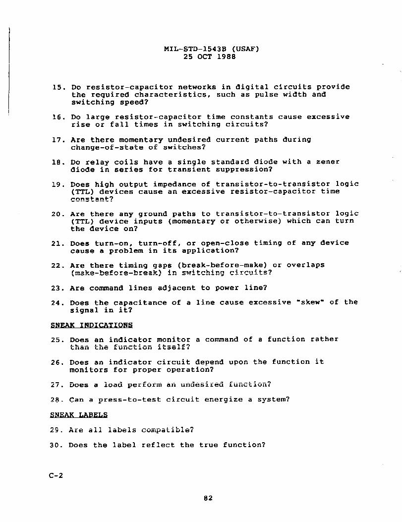
15. Do resistor-capacitor networks in digital circuits providethe required characteristics, such as pulse width andswitching speed?
16. Do large resistor-capacitor time constants cause excessiverise or fall times in switching circuits?
17. Are there momentary undesired current paths duringchange-of-state of switches?
18. Do relay coils have a single standard diode with a zenerdiode in series for transient suppression?
19. Does high output impedance of transistor-to-transistor logic(TTL) devices cause an excessive resistor-capacitor timeconstant?
20. Are there any ground paths to transistor-to-transistor logic(TTL) device inputs (momentary or otherwise) which can turnthe device on?
21. Does turn-on, turn-off, or open-close timing of any devicecause a problem in its application?
22. Are there timing gaps (break-before-make) or overlaps(make-before-break) in switching circuits?
23. Are command lines adjacent to power line?
24. Does the capacitance of a line cause excessive “skew- of thesignal in it?
K INDICATIONS
25. Does an indicator monitor a command of a function ratherthan the function itself?
26. Does an indicator circuit depend upon the function itmonitors for proper operation?
27. Does a load perform an undesired function?
28. Can a press-to-test circuit energize a system?
J?AK
29. Are all labels compatible?
30. Does the label reflect the true function?
c-2
tI
“)
MIL-STD”1543B (USAF)25 OCT 1988
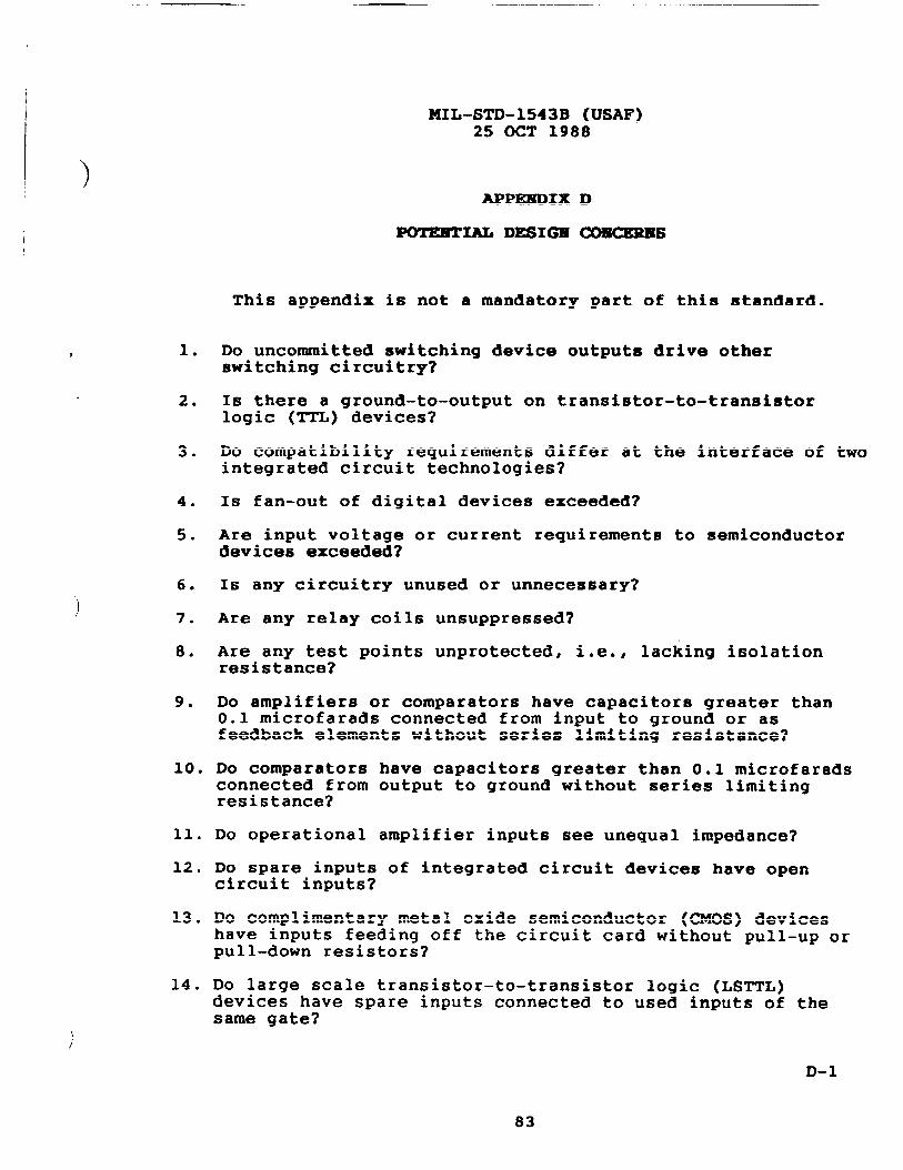
APPEEDIX D
POT’EETIAL DESIG19 C01!KKIU9S
This appendix is not a mandatory part of this standard.
1.
2.
3.
4.
5.
6.
7.
8.
9.
10.
11.
12,
13,
14 ●
Do uncommitted switching device outputs drive otherswitching circuitry?
Is there a ground-to-output on transistor-to-transistorlogic (TTL) devices?
Do compatibility requirements differ at the interface of twointegrated circuit technologies?
Is fan-out of digital devices exceeded?
Are input voltage or current requirements to semiconductordevices exceeded?
Is any circuitry unused or unnecessary?
Are any relay coils unsuppressed?
Are any test points unprotected, i.e., lacking isolationresistance?
Do amplifiers or comparators have capacitors greater than0.1 microfarads connected from input to ground or asfeedback elements without series limiting resistance?
Do comparators have capacitors greater than 0.1 microfaradsconnected from output to ground without series limitingresistance?
DO operational amplifier inputs see unequal impedance?
Do spare inputs of integrated circuit devices have opencircuit inputs?
Do complimentary metal oxide semiconductor (CMOS) deviceshave inputs feeding off the circuit card without pull-up orpull-down resistors?
Do large scale transistor-to-transistor logic (LSTTL)devices have spare inputs connected to used inputs of thesame sate?
D-1
83
MIL-STD-1543B (USAF)25 OCT 1988
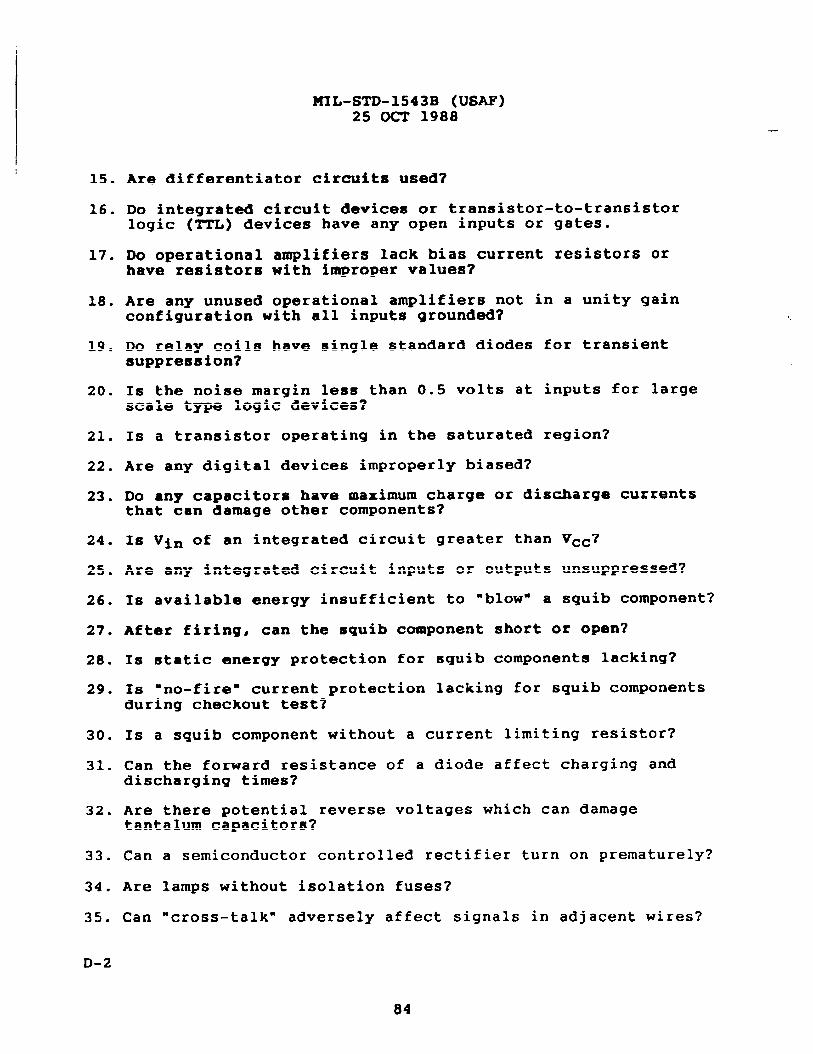
15. Are Uifferentiator circuits used?
16. Do integrated circuit devices or transistor-to-transistorlogic (TTL) devices have any open inputs or gates.
17. Do operational amplifiers lack bias current resistors orhave resistors with improper values?
18. Are any unused operational amplifiers not in a unity gainconfiguration with all inputs grounded?
19. Do relay coils have single standard diodes for transientsuppression?
20. Is the noise margin less than 0.5 volts at inputs for largescale type logic devices?
210 Is a transistor operating in the saturated region?
22. Are any digital devices improperly biased?
23. Do any capacitors have maximum charge or discharge currentsthat can damage other components?
24. Is Vin of an integrated circuit greater than Vcc?
25. Are any integrated circuit inputs or outputs unsuppressed?
26. Is available energy insufficient to “blow” a squib component?
27. After firing, can the squib component short or open?
28. Is static energy protection for squib components lacking?
29. Is “no-fire” current protection lacking for squib componentsduring checkout test?
30. 1s a squib component without a current limiting resistor?
31. Can the forward resistance of a diode affect charging anddischarging times?
32. Are there potential reverse voltages which can damagetantalum capacitors?
33. Can a semiconductor controlled rectifier turn on prematurely?
34. Are lamps without isolation fuses?
35. Can “cross-talk” adversely affect signals in adjacent wires?
D-2
MIL-STD-1543B (USAF)25 OCT 1988
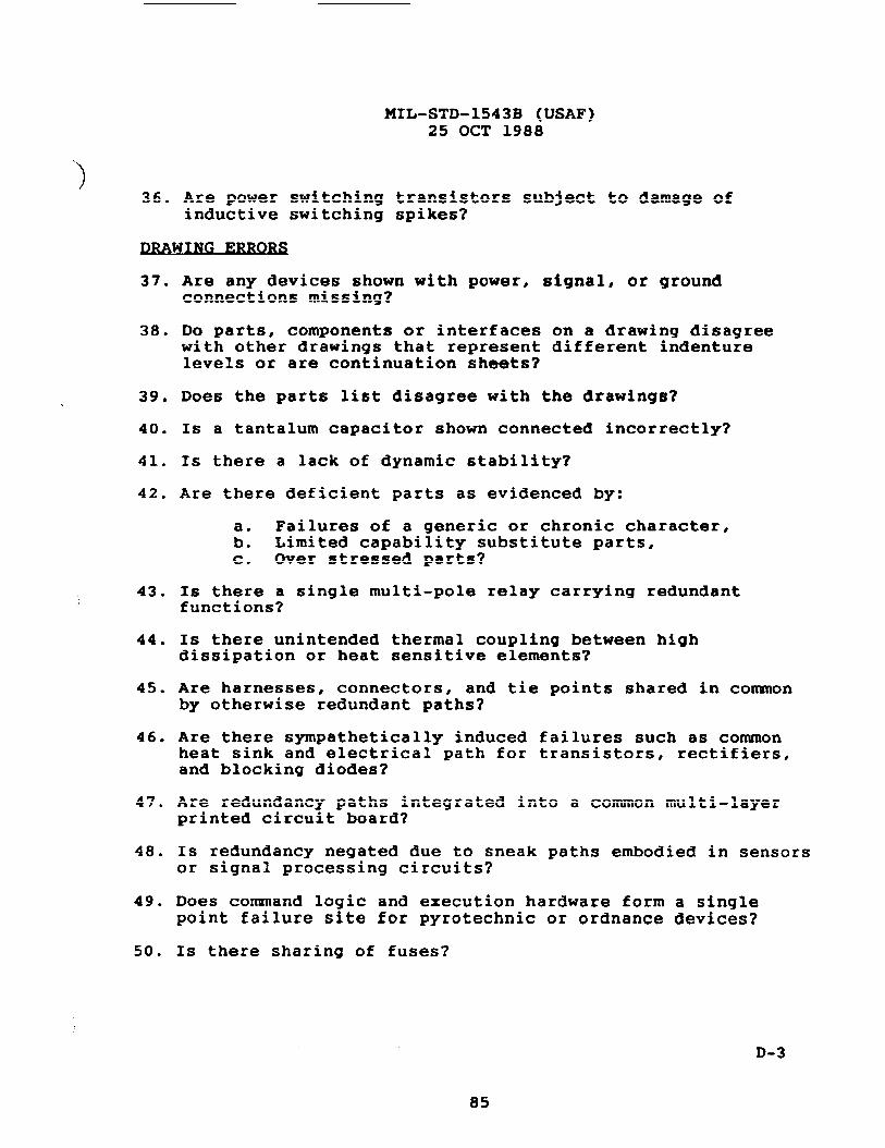
‘)36. Are power switching transistors subject to damage of
inductive switching spikes?
InA WING
37. Are any devices shown with power, signal, or groundconnections missing?
38. Do parts, components or interfaces on a drawing disagreewith other drawings that represent different indenturelevels or are continuation sheets?
39. Does the parts list disagree with the drawings?
40. Is a tantalum capacitor shown connected incorrectly?
41. Is there a lack of dynamic stability?
42. Are there deficient parts as evidenced by:
a. Failures of a generic or chronic character,b. Limited capability substitute parts,c. Over stressed parts?
43. Is there a single multi-pole relay carrying redundantfunctions?
44 ● Is there unintended thermal coupling between highdissipation or heat sensitive elements?
45. Are harnesses, connectors, and tie points shared in commonby otherwise redundant paths?
46. Are there sympathetically induced failures such as commonheat sink and electrical path for transistors, rectifiers,and blocking diodes?
47. Are redundancy paths integrated into a common multi-layerprinted circuit board?
48. Is redundancy negated due to sneak paths embodied in sensorsor signal processing circuits?
49. Does command logic and execution hardware form a singlepoint failure site for pyrotechnic or ordnance devices?
50. Is there sharing of fuses?
D-3
85
—— —.. ===——=-—-—=————-—.——————.———-—=—<=—.=—-——=—---————
MIL-STD-1543B (USAF)25 OCT 1988
..
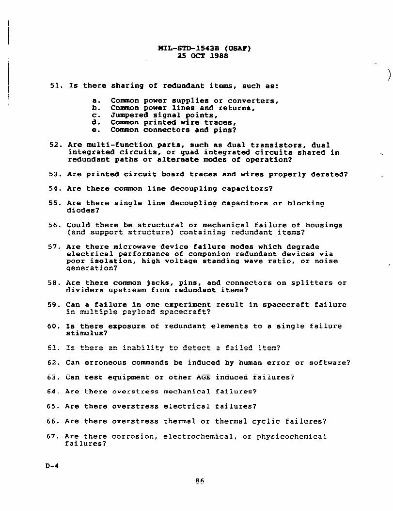
)51. Is there sharing of redundant items, such as:
a. Common power supplies or converters,b. Coxmnon power lines and returns,
Jumpered signal points,:: Conmon printed wire traces,e. Common connectors and pins?
52. Are multi-function parts, such as dual transistors, dualintegrated circuits, or quad integrated circuits shared inredundant paths or alternate modes of operation?
53. Are printed circuit board traces and wires properly derated?
54. Are there common line decoupling capacitors?
55. Are there single line decoupling capacitors or blockingdiodes?
56. Could there be structural or mechanical failure of housings(and support structure) containing redundant items?
57. Are there microwave device failure modes which degradeelectrical performance of companion redundant devices viapoor isolation, high voltage standing wave ratio, or noisegeneration?
58. Are there common jacks, pins, and connectors on splitters ordividers upstream from redundant items?
59. Can a failure in one experiment result in spacecraft failurein multiple payload spacecraft?
60. Is there exposure of redundant elements to a single failurestimulus?
61. Is there an inability to detect a failed item?
62. Can erroneous commands be induced by human error or software?
63. Can test equipment or other AGE induced failures?
64. Are there overstress mechanical failures?
65. Are there overstress electrical failures?
66. Are there overstress thermal or thermal cyclic failures?
67. Are there corrosion, electrochemical, or physiochemicalfailures?
D-4
86
e.. ------- ------ ., ---— -------- -
MIL-STD-1543B (USAF)25 OCT 1988
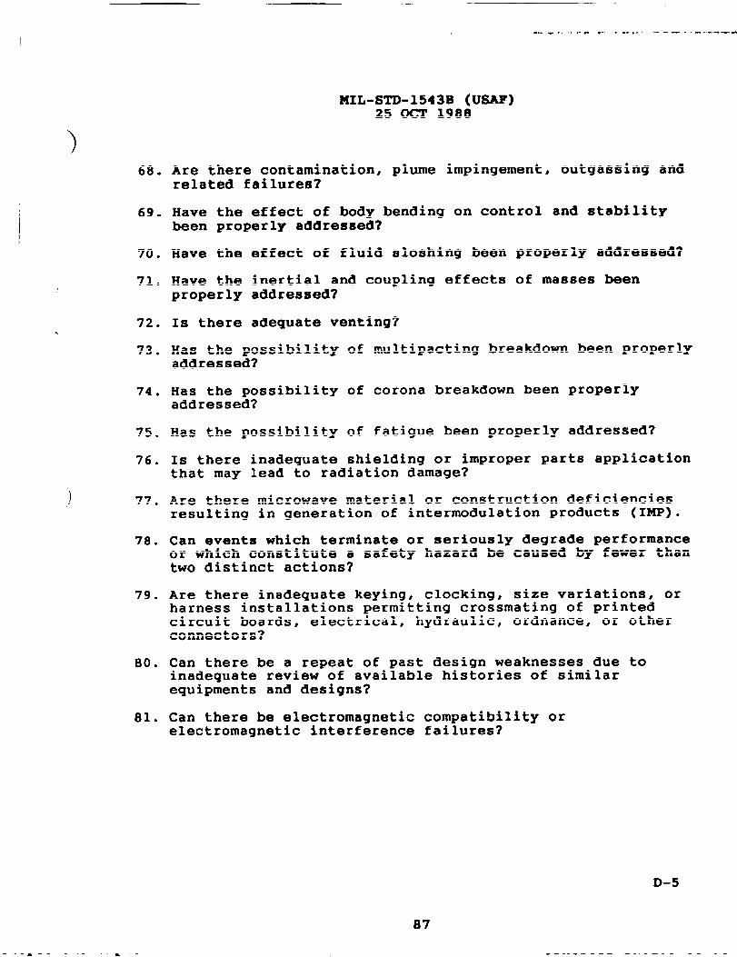
)68. Are there contamination, Plume imPin9ementt out9assin9 and
related failures?
69. Have the effect of body bending on control and stabilitybeen properly addressed?
70. Have the
71. Have theproperly
72. Is there
effect of fluid sloshing been properly addressed?
inertial and coupling effects of masses beenaddressed?
adequate venting?
73. Has the possibility of multipacting breakdown been properlyaddressed?
74 ● Has the possibility of corona breakdown been properlyaddressed?
75. Has the possibility of fatigue been properly addressed?
76. Is there inadequate shielding or improper parts applicationthat may lead to radiation damage?
) 77. Are there microwave material or construction deficienciesresulting in generation of intermodulation products (IMP).
78. Can events which terminate or seriously degrade performanceor which constitute a safety hazard be caused by fewer thantwo distinct actions?
79. Are there inadequate keying, clocking, size variations, orharness installations permitting crossmating of printedcircuit boards, electrical, hydraulic, ordnance, or otherconnectors?
80. Can there be a repeat of past design weaknesses due toinadequate review of available histories of similarequipments and designs?
81. Can there be electromagnetic compatibility orelectromagnetic interference failures?
D-5
87
KIL-sTD-X543B (USAF)25 (XT 1988
THIS PAGE INTENTIONALLY LEFT BLANK
D-6
‘\
‘.
MIL-STD-1543B (USAF)25 OCT 1988
IAPPmDxx E
APPLICABLE DATA REQUIREMKMTS
This appendix is not a mandatory part of this standarcl.
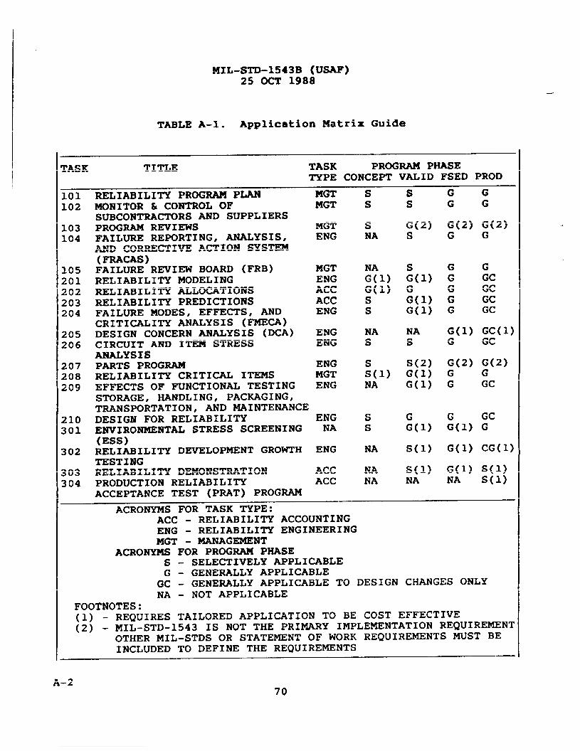
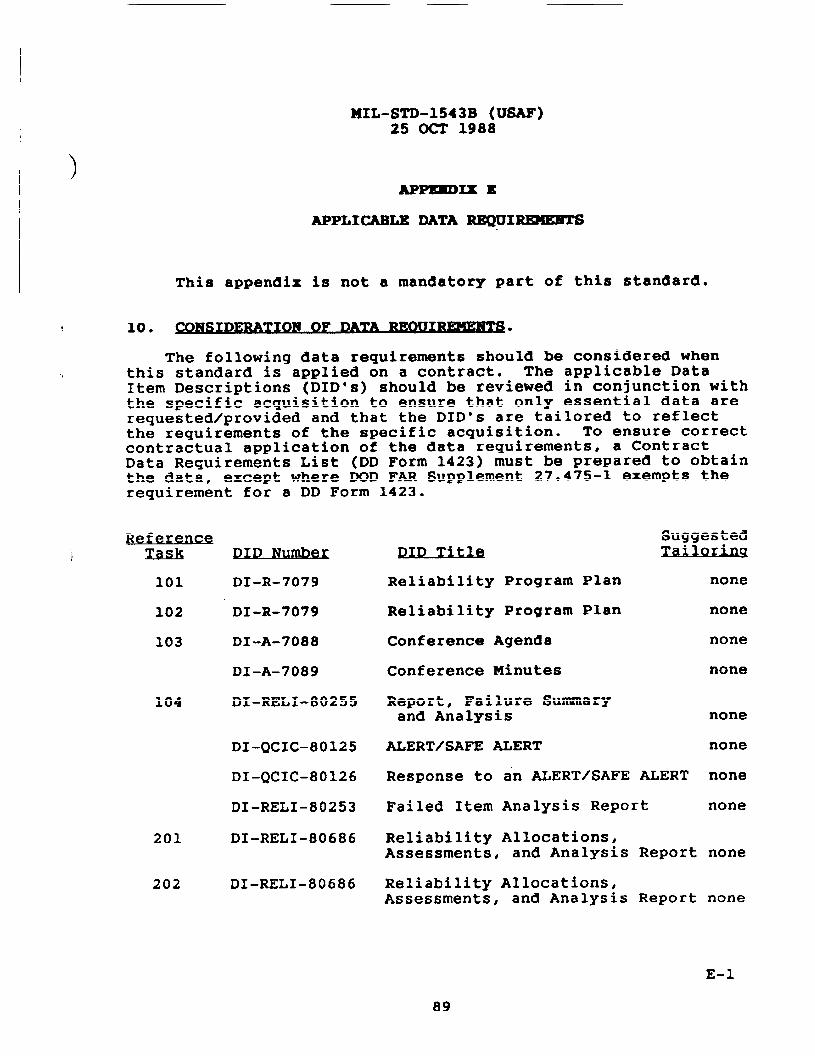
The following data requirements should be considered whenthis standard is applied on a contract. The applicable DataItem Descriptions (DID’s) should be reviewed in conjunction withthe specific acquisition to ensure that only essential data arerequested/provided and that the DID’s are tailored to reflectthe requirements of the specific acquisition. To ensure correctcontractual application of the data requirements, a ContractData Requirements List (DD Form 1423) must be prepared to obtainthe data, except where DOD FAR Supplement 27.475-1 exempts therequirement for a DD Form 1423.
104
201
202
Refe~%ask DID Numbez
101 DI-R-7079
102 DI-R-7079
103 DI-A-7088
DI-A-7089
DI-RELI-80255
DI-QCIC-80125
DI-QCIC-80126
DI-RELI-80253
DI-RELI-80686
DI-RELI-80686
SuggestedDID Ti- Zallorlu
● .
Reliability Program Plan none
Reliability Program Plan none
Conference Agenda none
Conference Minutes none
Report, Failure Summaryand Analysis none
ALERT/SAFE ALERT none
Response to an ALERT/SAFE ALERT none
Failed Item Analysis Report none
Reliability Allocations,Assessments, and Analysis Report none
Reliability Allocations,Assessments, and Analysis Report none
E-1
89
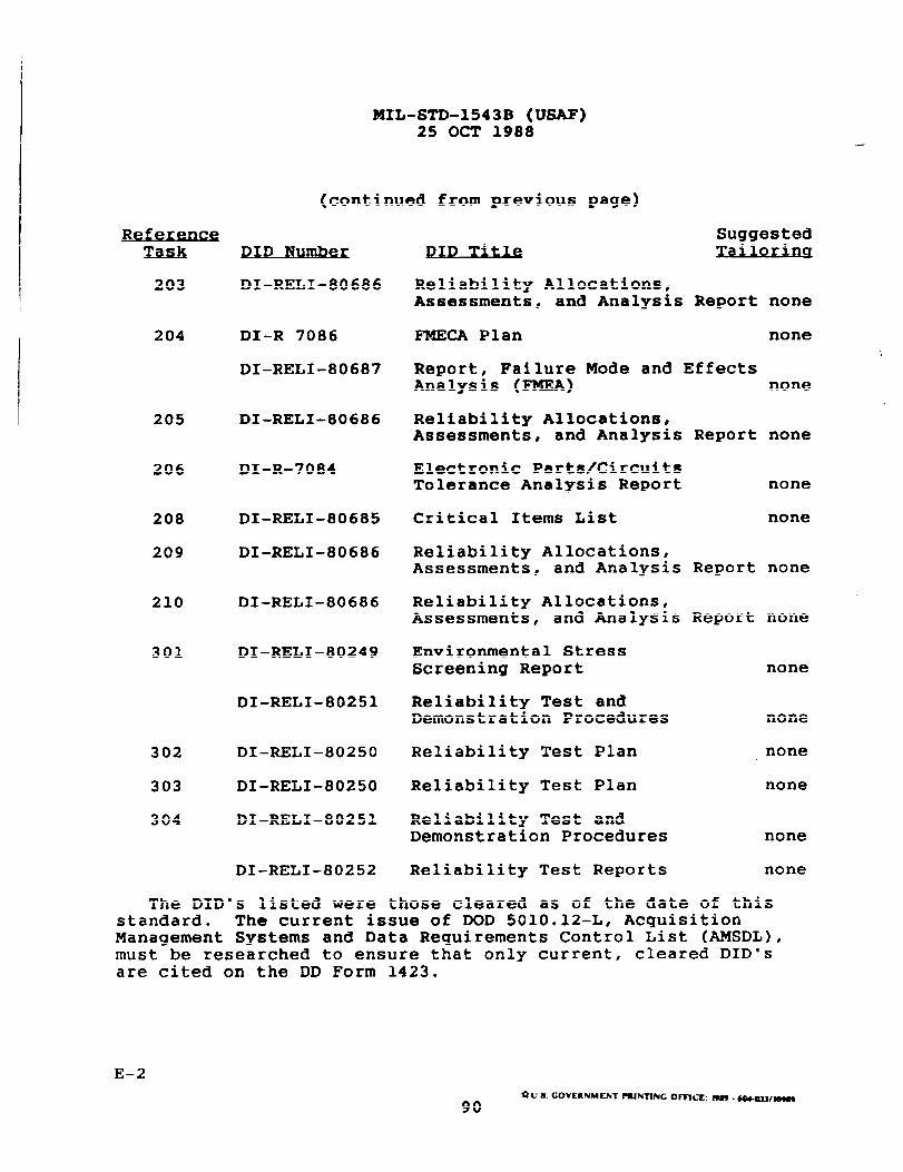
MIL-STD-1543B (USAF)25 OCT 1988
(continued from previous page)
Refer-Task
203
204
205
206
208
209
210
301
302
303
304
DID Nu~
DI-RELI-80686
DI-R 7086
DI-RELI-80687
DI-RELI-80686
DI-R-7084
DI-RELI-80685
DI–RELI-80686
DI-RELI-80686
DI-RELI–80249
DI-RELI-80251
DI–RELI–80250
DI-RELI-80250
DI-RELI-80251
DI-RELI-80252
SuggestedDID Tlti
.
Reliability Allocations,Assessments, and Analysis Report none
FMECA Plan none
Report, Failure Mode and EffectsAnalysis (FMEA) none
Reliability Allocations,Assessments, and Analysis Report none
Electronic Parts/CircuitsTolerance Analysis Report none
Critical Items List none
Reliability Allocations,Assessments, and Analysis Report none
Reliability Allocations,Assessments, and Analysis Report none
Environmental StressScreening Report none
Reliability Test andDemonstration Procedures none
Reliability Test Plan none
Reliability Test Plan none
Reliability Test andDemonstration Procedures none
Reliability Test Reports none
The DID’s listed were those cleared as of the date of thisstandard. The current issue of DOD 501O.12-L, AcquisitionManagement Systems and Data Requirements Control List (AMSDIJ),must be researched to ensure that only current, cleared DID’sare cited on the DD Form 1423.
E-2*u.s.GOVtRNMOdT ~N~NcomC~:r999.w4433/H
90
)
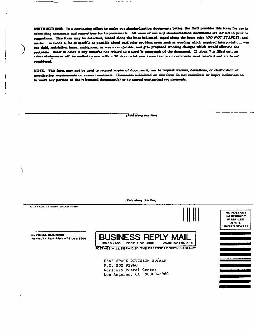
IB ● Ootatimlaiagdfore tom8ke Oar
*
(hht along thtiIbu)
DEFENSE LOGISTICS AGENCY
1111110; FOCIAL UWNES
>ENALTV FOR ●nlVATE USE $300t BUSINESS REPLY MAIL II FIRST CLASS PERMIT NO. 4966 WASHINGTON O. C j1 BPO-AGE WILL BE PAID BY THE DEFENSE LOGl~lCS AGENCY
USAFSPACEDIVIS1ONSD\ALMP.O.BOX 92960WorldwayPostalCenterLosAngeles,CA 90009-2960
IINO POSTAGE
N6CESSARV
IF MAILED
IN THE
UNITED STATES
.
I
I
I
I(“II1I
III
I
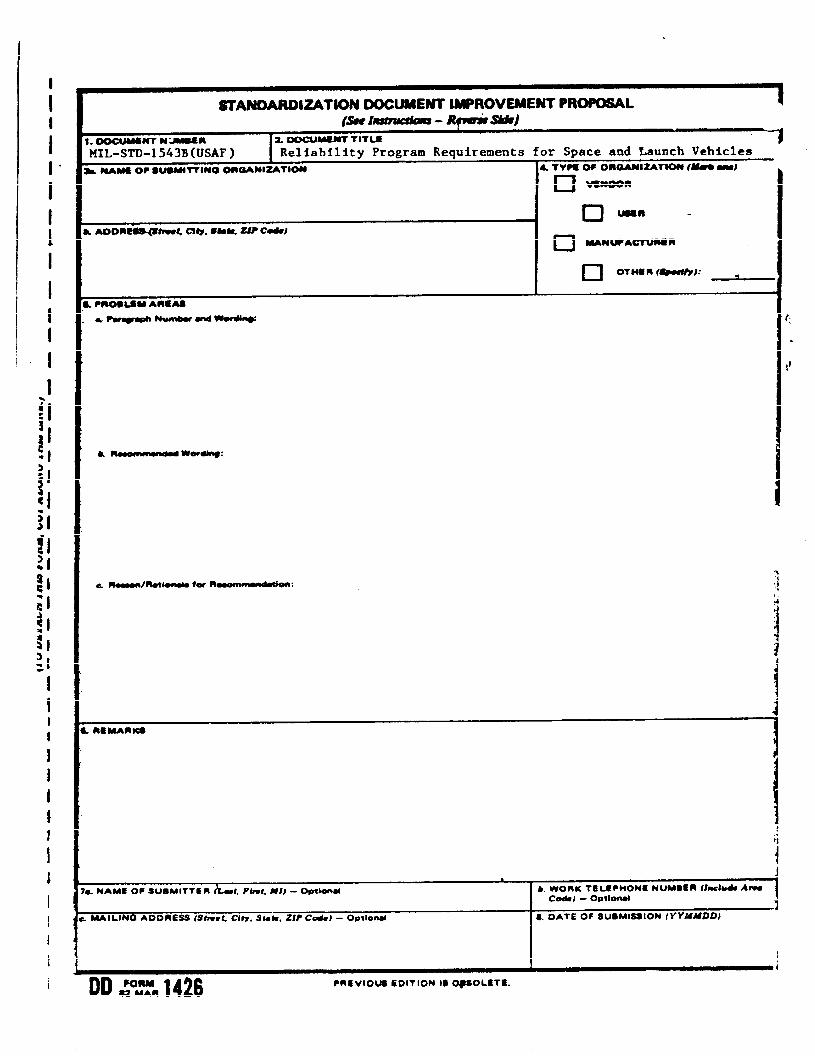
ST’ANDARDIZATIN DOCUMENT lMPROVEMEM’ PROPOSALI
B. OOCUMSNT N“-n
MIL-STD-1543B(USAF) ReliabilityProgramRequirementsfor SpaceandLaunchVehicleshMAM60PsusMtnlNo onoAN1-TloN 4TVMOFOmWl=TW (--J
u Wmoon
‘j,,4
ia
). NAME OF SLtSMITTER &w t, Flnt, Ml) - Optmnti b. WORK 76 LCPHONE NUMSER (lnchb& Amcods) - OetloMl 1
I 4MAIL(N6 AOORESS(StneL City. Stab, ZIP Cods)- OVtiaut 8. DATE OF SUBMISSION (YYXUPD)
I II
DD FORM- MAR 1426 ●CVIOUS EDITION 1$ 0#SOL6Tt
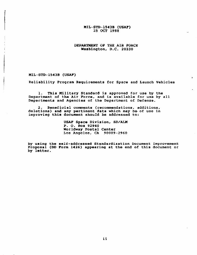
MIL-STD-1543B (USAF)25 OCT 1988
DEPARTMENT OF THE AIR FORCEWashington, D.C. 20330
MIL-STD-1543B (USAF)
Reliability Program Requirements for Space and Launch Vehicles
1. This Military Standard is approved for use by theDepartment of the Air Force, and is available for use by allDepartments and Agencies of the Department of Defense.
2. Beneficial comments (recommendations, additions,deletions) and any pertinent data which may be of use inimproving this document shouId be addressed to:
USAF Space Division, SD/ALMP. O. 130x 92960Worldway Postal CenterLos Angeles, CA 90009-2960
by using the self-addressed Standardization Document ImprovementProposal (DD Form 1426) appearing at the end of this document orby letter.
ii
)
MIL-STD-1543B (USAF)25 OCT 1988
mREmRD
The high reliability required of all space and launchvehicles is achieved by the designs$ including the designmargins, and by the manufacturing processes and controls imposedat every level of fabrication assembly~ an~ test. The designand design margins should ensure that the equipment is capableof performing in the operational environment. The reliabilityprogram requirements stated in this standard have beenestablished to ensure the timely and economical attainment ofsystem reliability as an integral part of the acquisitionprocess. The requirements are a composite of those that havebeen found to be cost effective on previous space programs.
This standard provides a consistent approach to helpachieve, in a cost effective way, the high reliability requiredfor space and launch vehicles. For the convenience of the userof this standard, it is organized similar to MIL–STD-785B,“Reliability Program for Systems and Equipment Development andProduction, “ although this standard is an independent document.
The requirements of this standard complement other typicalcontract provisions~ such as the requirements for qualityassurance in MIL-STD–1586, “Quality Program Requirements forSpace and Launch Vehicles”; the requirements for a PmtstMaterials, and Processes Control Program in MIL-STD-1546,“Parts, Materials, and Processes Standardization, Control, andManagement Program for Spacecraft and Launch Vehicles”; and thetesting requirements in MIL-STD-1540, “Test Requirements forSpace Vehicles.”
When preparing their proposal, a contractor may includeadditional tasks or task modifications. Such added tasks or taskmodifications should be clearly identified, include supportingrationale, and be independently priced for ease of evaluation.Contractors are always encouraged to report to the contractingofficer, for program office review and consideration, thosespecific requirements that seem inappropriate, are believedexcessive, or are conflicting with other contract requirements.However, contractors are reminded that any departure fromcontractually imposed requirements can be granted only by thecontracting officer.
iii
-——
IIIL-STD-1543B (USAF)25 (XT 1988
--
THIS PAGE INTENTIONALLY LEFT BLANK
iv
I
‘
KIL-STD-1543B (USAF)25 OCT 1988
CmmKETs
PAGE
1. SCOPE ● .*...*-* ● ..*..**. ● e*m **a** 9.mma 9a** ● *.**..** ● *****
1.1 PURPOSE ● .9. we*.. 9**. *em*. .* ...*..* ... **9.** ● *.***..* .9-
1.2 APPLICABILITY ● ..*****. ● .* ****me ● .e*. .**9 ● .* *mm*.* ● *.***
1.2.1 Application of the Standard .............c.... ........1.2.2 Application Guidance ......● 9*0e*e0* ● ******** ● o****o**
2. REFERENCED DOCUMENTS ● **.**** . ..9.9.. ● **** ● *e OO*OO* ● **O**
2.1 GOVERNMENT DOCUMENTS ● 8*0*9*** ● **O*09W9 ● OmOOO*** ● e*eoe*o
2.2 ORDER OF PRECEDENCE ● **a****m ● **eO**** ● Oe***mm* 9********
3. DEFINITIONS AND ACRONYMS ...● ****.*** ● *e. *m **e .* ***..** ● a
3.1 DEFINITIONS ............... .* ...***. ● *.****** ● *******m ● O
3.1.1 Acquisition Activity ● *O****** ● ****9*8* 99******* ● 8*9**3.1.2 Acquisition Phases ...*.**** .99 .*9*** ● .****..* ● *mm *e*.
3.1.2.1 Conceptual (CONCEPT) Phase.........ao.co...c. . .. o..
3.1.2.2 Demonstration. and Validation (VALID) Phase .........3.1.2.3 Full-scale Engineering Development (FSED) Phase ....3.1.2.4 Production (PROD) Phase .......................o~.ce3.1.3 Circuit and Item Stress Analysis ......● **.*..* ● 9e.98m
3.1.4 Compensating Features ● am*8*** ● ****m** ● ***9*** ● -****9*3.1.5 Component. ....................● ● ● ● ● . ● ● ● ● . ● ● ● ● ● . ..* ● ● ●
3.1.6 Contracting Officer.. ..........................~-.a..3.1.7 Correlated or Sympathetic Failure ....................3.1.8 Critical Items .......................................3.1.9 Failure Effect ● ● ● .● *● *● *● ● *.*● ● ** ● *● ● *● a* ● *● ● ● m*em ● *.
3.1.9.1 Local Effect ● ***O*** ● ******* ● *O***.* ● 0m***b* ● 99****3.1.9.2 Next Higher Level Effect ● **D*.** ● **a am*. ● *m***** ● *e
3.1.9.3 End Effect .....● m.*99* ● ****** ● *.**** ● **m9*e ● ****9* ●
3.1.10 Failure Mode ● **.*** ● *9**** ● ****e* ● ***9 .* .*9*8* ● ***.*
3.1.11 Government Industry Data Exchange Program (GIDEP) ...3.1.12 GIDEP Alert ● *e**e** ● *9***** ● ******9 ● O**9*9W 98****** ●
3.1.13 Level of Indenture ..................................3.1.14 Mean Mission Duration ....9******* ● *****e* ● .*9*88* ● *93.1.15 Pin-fault Analysis.. ................................
1
1
111
3
3
4
5
5
5555555666667777888888
MIL-STD-1543B (Us=)25 OCT 1988
CO~S (Continued)
PAGE
I
3.1.16 Single Point Failure (SPF) ● .*.*9*8 ● ******9 ● =*****” “’
3.1.17 Sneak Condition .....● ..**** ● **O***b...*.** ● ****9* ● =*
3.1.18 System ● m....a ......e● w***** ● *.**-* ● **..em.~e ● **=**” ●
3.1.19 Tailoring ..............................****m ● ****** ●
3.1.20 Timely ..........99.. ● *****e ● *****” ● *........● *e**9**
3.2 ACROSS ........● .***......**9 ● **am** ● D*.**- ● **”***‘0=0
4* GENERAL REQUIR~NTS. ...................................
4.1 RELIABILI~PROG~. ...................................
4.2 Quantitative REQUIR~NTS. .............................
4.3 INTEGRATION WITH OTHER REQUIR~NTS ....................
4.4 INTEGRATED EQUII?MENT....**me ● *v**.** .* ● ..*.** ● .***** ● **
5. DETAILED REQUIR=NTS .........*.*-. ● ***.,*“*-”*”* ““..*O
SECTION 100. PROGU SURVEILLANCE AND CONTROL TASKS ........
TASK
101 RELIABILI~ PROGM PLAN ............**** O*.***** ● *****
102 MONITORING AND CONTROL OF SUBCONT~CTORSAND SUPPLIERS ● *..... ● .*****9**=*** ● ***”.**** ● ● ● *● ● W● *●
103 PROGRAM REVIEWS .......................................
104 FAILURE REPORTING, ANALYSIS, ANDCORRECTIVE ACTION SYST= (FRACAS) .....................
105 FAILURE REVIEW BOARD (FRB) ● *****.* ● =**””*” ‘*..*. ● ● *● *●
SECTION 200. DESIGN AND EVALUATION TASKS ...................
TASK
201 RELIABILX~ MODELING ..................................
999910
10
11
11
11
11
11
13
15
17
19
21
23
27
29
31
...
vi
MIL-STD-1543B (USAF)25 OCT 1988
CONTENTS (Continued)
#
202
203
204
205
206
207
208
209
210
RELIABILITY ALLOCATIONS ● ***O**** ● *0***080 w*e**,90, .***
RELIABILITY PREDICTIONS ...99*** ● 0a**em* ● amO**e* ● 9***m*
FAILURE MODES, EFFECTS, AND CRITICALITYANALYSIS (FMECA) ..***** ● **.*** ● **...*.****** ● ****** ● ***
DESIGN CONCERN ANALYSIS (DCA) ● ● 0● 9*● *m● *● ● *● ● *● ● ● ● ● ● ● Q
CIRCUIT AND ITEM STRESS ANALYSIS ● ***cam ● =****** ● ***.**
PARTS, MATERIALS, AND PROCESSES (PMP)PROGRAM ...............................................
RELIABILITY CRITICAL ITEMS ● *****8* ● e***a*O ● ******* ● *9*
EFFECTS OF FUNCTIONAL TESTING/ S~mGE, HANDLINGJPACKAGING, TwNSPORTATION, AND MAINTENANCE ............
DESIGN FOR RELIABILITY ● ****** ● -**O** ● *****. ● *****. ● *=*
SECTION 300. DEVELOPMENT AND PRODUCTION TESTING TASKS.. ....
TASK
301
302
303
304
ENVIRONMENTAL STRESS SCREENING (ESS) ● *● ** ● *● ● ● ● ● *● ● ● 9*
RELIABILITY DEVELOPMENT GROWTH TEST(RDGT) PRoGwOf ● ****** ● ****** ● **O*** ● *9**** ● ****** ● *O**
RELIABILITY DEMONSTRATION .......0.**.***- ● -****** ● ****
PRODUCTION RELIABILITY ACCEPTANCE TEST(PRAT) PROGRAM ● ***m.*m ● **mm*mm ● em*em*. ● ****-** 8*-.****
APPENDIX A
APPENDIX B
APPENDICES
PAGE
33
35
37
47
49
51
53
55
57
59
61
63
65
67
APPLICATION GUIDANCE FOR IMPLEMENTATION OFMIL-STD-1543 .................................. 69
SNEAK ANALYSIS FUNCTIONAL CLUE LIST ........... 79
vii
MIL-STD-1543B (USAF)25 OCT 1988
CORT’KHTS (Continued)
PAGE
APPENDICES (Continued)
APPENDIX C DESIGN CLUE LIST ● ● ● ● b● ● *● ● ● ● ● ● w● ● ● ● ● -● ● 99● D*● * 81
APPENDIX D POTENTIAL DESIGN CONCERNS. .................... 83
APPENDIX E APPLICABLE DATA REQUIREMENTS .................. 89
TABLES
Table A-1 APPLICATION MATRIX GUIDE. ..................... 70
viii
mbsm-1543B (USAF)25 OCT 1988
SECTIO19 1
SCOPE
1.1
This standard establishes uniform reliability programrequirements and tasks for use during design, development,fabrication, test, and operation of space and launch vehicles.
1.2.1 s~ This standard, whenappropriately tailored, is applicable ~o all prime, associate,and subtier contractors involved in the design, development,fabrication, test, and initial operation of space and launchvehicles.
1.2.2 Amlmatmn Guzdam. . . Application guidance for
tailoring requirements to a par~icular procurement is containedin Appendix A. Appendix A and the ‘DETAILS TO BE SPECIFIED BYTHE ACQUISITION ACTIVITY- paragraph at the end of each taskcontain no contractor tasking, either directly or implied.
,)1
MIL-STD-1543B (USAF)25 OCT 1988
THIS PAGE INTENTIONALLY LEFT BLANK
2
II
MIL-STD-1543B (USAF)25 OCT 1988
SECTIO19 2
REF’ERRNCED ~s
Unless otherwise specified, the following specifications,standards, and handbooks of the issue listed in that issue of
. the Department of Defense Index of Specifications and Standards(DoDISS) specified in the solicitation form a part of thisstandard to the extent specified herein.
MIL-STD-721 Definitions of Terms for Reliability andMaintainability.
MIL-STD-756 Reliability Modeling and Prediction
MIL-STD-882 System Safety Program Requirements
MIL-STD-1521 Technical Reviews and Audits forSystems, Equipment and Computer Programs
MIL-STD-1540 Test Requirements for Space Vehicles
MIL-STD-1546 Parts, Materials, and ProcessesStandardization. Control, and ManagementProgram for Spacecraft and LaunchVehicles
MIL-STD-1547 Technical Requirements for Parts,Materials, and Processes for Space andLaunch Vehicles
MIL-STD-1556 Government Industry Data Exchange Program
MIL-STD-1629 Procedures for Performing a FailureMode, Effects and Criticality Analysis
MIL-STD-1635 Reliability Growth Testing
tarv Handbooks
MIL-HDBK-189 Reliability Growth Management
MIL-HDBK-217 Reliability Prediction of ElectronicEquipment
3
MXXJ-STD-1543B (USAF)25 OCT 1988
NPRD-3 Honelectronic Parts Reliability Data,Reliability Analysis Center RADC
(Copies of this document may be obtained from Rome AirDevelopment Center, Reliability Analysis Center, RADC/RAC,Griffiss Air Force Base, NY, 13441-5200)
(Copies of specifications, standards, and publications requiredby contractors in connection with specific procurement functionsshould be obtained from the acquisition activity or as directedby the contracting officer).
2-2 ~
In the event of a conflict between the text of this standardand the references cited herein, the text of this standard shalltake precedence. However, nothing in this standard shallsupersede applicable laws and regulations unless a specificexemption has been obtained.
MxL-STD-1543B (USAF)25 OCT 1988
SECTION 3
DEFIllITIOIUSAND ACRONYMS
Terms are in accordance with the definitions of MIL-STD-721,MIL-STD-1521, MIL-STD-1556, MIL-STD-1629, and the followingdefinitions:
3.1.1● ●
on The acquisition activity isthe Government office or agency-acquiring the equipment, system,or subsystem to which this standard is being contractuallyapplied.
3.1.2 on P-
3.1.2.1 ~0 The con-ptu’l phaseis the initial program acquisition phase that involves theidentification and exploration of alternate solutions orsolution concepts to satisfy a validated operational need.
3.1.2.2 stun Valid-n (V*] P- Thedemonstration and validation phase is the program acqui~itionphase when selected candidate solutions are refined throughextensive study and analyses; hardware development ifappropriate; test; and evaluations Feasibility of one or morecandidate solutions to satisfy the operational need isdemonstrated.
3.1.2.3●
eerlnu Develo~mt (FSER) P-The full-scale engineering development phase is the program
0
acquisition phase when the system and the principal itemsnecessary for its support are designedt fabricated testedt andevaluated.
3.1.2.4 Prodution● {PROD> Ph~ The production phase is
the program acquisition phase that s~arts with productionapproval and extends until the last system is delivered andaccepted.
3.1.3 circuit Item S-S●and Sls 0 Circuit and item
stress analysis relates parts stress to circuit, module,component (unit)~ subsystem and system performance and
)/
MIL-STD-1543B (USAF)25 OCT 1988
reliability, including influence by worst case parametervariations resulting from environmental effects~ radiationeffects, aging, input and output limitst initial operatingpoints, and initial tolerances.
3.1.4 Comvensama Featur~ ● Compensating features arespecial inspections, tests, controlst instructions drawingnotes or other provisions applied to a single point failure modeitem to improve reliability and lessen chances of failure.
3.1*5 CQRKW=W. A component is a functional unit thatis viewed as an entity for purposes of analysist manufacturing~maintenance, or record keeping. Examples are hydraulicactuators, valves, batteries electrical harnesses~ andindividual electronic boxes such as transmitters~ receivers~ ormultiplexer. Care should be exercised when the term componentis encountered in other documents since~ in some segments ofindustry, a piece part is referred to as a component and theterm “unit” is interchanged with the term component.
3.1.6 flc~.a A contracting officer is aperson with the authority to e~ter into, administer, orterminate contracts and make related determinations andfindings. The term includes authorized representatives of thecontracting officer acting-within the limits of their authorityas delegated by the contracting officer.
3.1.7. Ftiure.
atktlc A correlated orsympathetic failure is the inability of two ~or more) items toperform their function as the result of some single event, thuspossibly negating redundancy and acting as a single pointfailure mode (SPFM) (e.g., loss of a raceway containingredundant power leads or a pyrotechnic shock causing parallelrelays to chatter).
3.1.8 ~. Critical items are those itemswhich require special attention because of complexity,application of state-of-the-art techniques, the impact ofpotential failure, or anticipated reliability problems. Thefollowing are typical circumstances which would cause an item tobe included on a critical items list.
a. Failure of the item would lead directly to severeinjury or loss of human life.
b. A failure of the item would seriously affectsystem operation or cause the system to notachieve mission objectives. (See single pointfailure.)
MIL-STD-1543B (USAF)25 OCT 1988
‘)
)
c.
d.
e.
f.
9*
h.
i.
k.
A failure of the item would prevent obtaining datanecessary to evaluate accomplishment of missionobjectives.
The item has exhibited an unsatisfactory operatinghistory relative to required performance orreliability.
The item has stringent performance requirements inits intended application relative tostate-of-the-art.
The item does not have sufficient history orsimilarity to other items having demonstrated highreliability to provide confidence in itsreliability.
State-of-the-art techniques are required tomanufacture the item.
The items are stressed in excess of deratingcriteria.
The item has an operating, shelf-life, orenvironmental exposure limitation which warrantscontrolled storage or use.
The item is known to require special processing,handling, transportation, storage or testprecautions.
The item’s past history, nature, function, orprocessing warrants total traceability.
3.1.9 ~e Effect The failure effect is theconsequence of the failur; mode including primary and secondaryeffects. Consideration should be given to long terraas well asinitial effects and should consider all modes of operation.
3.1.9.1 ~. The local effect is theconsequence(s) of a failure mode on the operation, function, orstatus of the specific item being analyzed.
3.1.9.2 t●
er Level Effect 0 The next higher leveleffect is the consequence(s) of a failure mode on the operation,functions, or status of the items in the next indenture levelabove the indenture level under consideration.
3.1.9.3 nd Effect ● The end effect is the consequence(s)a failure mode has on the operation, function, or status of thehighest indenture level.
7
MIL-SZ!D-1543B (USAF)25 (XT 1988
3.1.10 ~. A failure mode is the way or mannerin which an item fails.
3.1.11 Prom CGI~EPlThe GIDEP is a program for the collection and exchange of
*
reliability and other technical information between governmentagencies and industry. (See MIL-STD-1556.)
3.1*12 ~. A GIDEP Alert is a means ofdissemination of information relating to an item deficiencywhich has been encountered, usually concerning parts, materials,or processes and their application.
3*~913 ~= The level of indenture of anitem is a designation which identifies its relative complexityas an assembly or function. In a system the first indenturelevel is the system. Examples of lower indenture levels couldbe system segments (level 2), prime items (level 3), subsystems(level 4), components (level 5), subassemblies or circuit boards(level 6), and parts (level 7).
3.1.149
n atl~ The mean mission durationis the average time an on-orbit s~ace system is operationalbefore a mission critical failure occurs. The mean missionduration is equivalent to mean time to failure for nonrepairableground systems. The mean mission duration can be determinedusing the following formula, which may be calculated truncatedat the end of some specified value or truncated at the time thecontractor estimates wear out or depletion of expendable willoccur.
T
Mean Mission Duration =f
R(t)dt
t-o
where R(t) = Mission reliability model functionT = Time at truncation
3.1.15 ~n-f~t ● A pin-fault analysis is asystematic design evaluation that examines, analyzes, anddocuments all potential inadvertent or spurious openings orclosures of current-carrying paths, and determines the effect ofeach failure (e.g., analysis of connector pin-to-pin shorts,pin-to-ground shorts, inductive or capacitive coupling, printedwiring board traces open or short, and harness wiring opens orshorts).
8
i
MIL-STD-1543B (USAF)25 OCT 1988
3.1.16 ~. A Single Pointfailure is any single hardware failure or software error whichresults in irreversible degradation of item mission performancebelow contractually specified levels. (The way or manner inwhich a single point failure of an item occurs is the singlepoint failure mode (SPFIW)of the item).
3.1.17 Sneak Contitia●
A sneak condition is a conditionwhich causes the occurrence”of an unwanted function or inhibitsa desired function even though all components function properlywhether electrical, mechanical, chemical, or software. Sneakconditions include:
a.
b.
c.
d.
Sneak paths, which are current paths that cause anundesirable function to occur or inhibit a desiredfunction even though no component failure hasoccurred.
Sneak timing, which is incompatible hardware orlogic operational sequences which can cause anundesirable function to occur or inhibit a desiredfunction.
Sneak indicators, which are circuits which allowimproper operation or control of sensors or theirdisplay devices that can indicate false orambiguous system status.
Sneak labels, which are imprecise instructions ornomenclature on controls and operating consolesthat lead to operator errors.
3.1.18 ~. A system is a composite of equiPment~skills, and techniques capable of performing or supporting anoperational role, or both. A complete system includes allequipment, related facilities, material, software, services, andpersonnel required for its operation and support to the degreethat it can be considered a self-sufficient item in its intendedoperational environment. The term system is also used in thisstandard to refer to the highest level of requirements andresource grouping applicable to the particular contract andanalysis.
3.1.19 ~lorinq Tailoring is the process by which theindividual requiremen~s (tasks, sections, paragraphs, words orphrases, or sentences) of the specifications and standards areevaluated to determine the extent to which each requirement ismost suited for a specific material acquisition and themodification of these requirements, where necessary, to ensurethat each tailored document invokes only the minimum needs ofthe government.
),9
MIL-STD-1543B (USAF)25 (XT 1988
3.1.20 ~. As used in this standard, timelyperformance of a task, subtask, or effort is performance at atime when the results will be available to allow managementactions to be taken to preserve system reliability, and to avoidor minimize schedule delays and cost impacts.
CDR
CONCEPT
ESS
FMECA
FIUKAS
FRB
FSED
GIDEP
PDR
PMP
PROD
RDGT
sow
SPF
SPFM
VALID
Critical Design Review
Conceptual phase of program acquisition
Design Concern Analysis
Environmental Stress Screening
Failure Mode Effects and Criticality Analysis
Failure Reporting and Corrective Action System
Failure Review Board
Full-scale engineering development phase ofprogram acquisition
Government Industry Data Exchange Program
Preliminary Design Review
Parts, Materials, and Processes
Production phase of program acquisition
Reliability Development Growth Test
Statement of Work
Single Point Failure
Single Point Failure Mode
Demonstration and validation phase cf programacquisition
10
mm -- . . . _.,_ __.. ..”
— ,
MIL-STD-1543B (USAF’)25 OCT 1988
)
SECTIOX!l4
GENERAL REQUIREHEHTS
4.1 ~
The prime, associate, and subtier contractors shallimplement and maintain a reliability program that is planned,scheduled, integrated, and developed in conjunction with otherdesign, development, and production functions in accordance withthe contractual statement of work, the requirements of thisstandard, and the program plan approved by the acquisitionactivity. The contractor shall establish and maintain aninternal system of directives, procedures, instructions,specifications, and manuals to implement the contractuallyrequired reliability program. The program level of effort shallbe adequate to fulfill the contractual quantitative andqualitative reliability requirements, and to support economicalachievement of overall program objectives.
4.2 ~
The minimum acceptable item reliability shall be as statedin the configuration item specification. Quantitativereliability requirements for all major items shall be stated inthe appropriate section of each item specification. Thequantitative values not defined by the contracting officer, andthose to be allocated from the system requirements, shall beestablished by the contractor though trade-off analyses prior tothe Preliminary Design Review (PDR), and shall be updated forthe Critical Design Review (CDR) and subsequent formal reviews.
4.3
The reliability program effort shall be closely coordinatedwith the design engineering and test programs as well asconfiguration management and integrated logistic support. Thereliability program shall also be closely integrated with therelated disciplines of quality assurance; maintainability; humanengineering; system safety; software development; and parts,materials, and processes control to precludeeffort and produce integrated cost-effective
4.4 ~
Where items such as government furnished
duplication of .results.
equipment ordirected source hardware-are to be integrated into the end item,known or estimated reliability predictions and analyses for
)
11
MIL-STD-1543B (USAF)25 OCT 1988
these items shall be used in the contractor’s reliabilitypredictions and other analyses. Reliability related problemsintroduced by inclusion of such items shall be identified to thecontracting officer.
—
12
I r
MIL-STD-1543B (USAF)25 OCT 1988
SECTION 5
DETAILED REQUIREMENTS
The detailed requirements are contained in the followingtask descriptions.
.
)
.— . —————————.- -—-—————
13
MIL-STD-1543B (USAF)25 OCT 1988
THIS PAGE INTENTIONALLY LEFT BLANK
—
E-cl cl-l-1
-. .-. .
MIL-STD-1543B (USAF)25 OCT 1988
‘\
SECTION 100
PROGRAM SURVEILLANCE JWD CONTROL TASKS
15
MIL-STD-1543B (USAF)25 OCT 1988
—
THIS PAGE INTENTIONALLY LEFT BLANK
16
MIL-STD-1543B (USAF)25 XT 19S8
),
)
TASK 101
RELIABILITY PROGRAM PLAN
Iol.1 EmEQs!E
The purpose of Task 101 is to require the contractor todevelop a reliability program plan which identifies andintegrates all program tasks required to accomplish contractualreliability requirements.
101.2 ~
101.2.1 A reliability program plan shall be prepared andshall include the following:
a.
b.
c.
d.
A description of how the reliability program willbe conducted to meet the tailored requirements ofthis standard as specified in the contract, and toensure that quantitative reliability requirementsare met.
A detailed description of how each reliabilitytask, including contractor added or modified tasks,is to be performed or complied with, includingestimated time phasing. The purpose and expectedresults of each task and the planned methods formonitoring, assessing, reporting, and takingappropriate action regarding the status,accomplishments, and problems shall be described.
A description of the contractor’s organizationalelement assigned responsibility and authority forimplementing the reliability program tasks. Keypersonnel managing the reliability program shall beidentified by name and title.
The identification of analyses or data basesrequired by the reliability program which maysatisfy or be satisfied by an analysis or data basefrom a related design or specialty engineeringfunction. The plan shall identify common users,earliest requirement, and variations in content andformat for each user. Common requirements of thefunctional areas listed in paragraph 101.2.l.e as aminimum shall be considered. As an example, acomputer-aided engineering data base would be usedto obtain application data for use in performing areliability prediction.
17
-. . -- . . - - . ---- --- ~__—.I - .
MIL-STW1543B (USAF)25 OCT 1988
-.
e. Interfaces between the reliability program andrelated programs or functions including as aminimum:
(1)(2)(3)(4)(5)(6)(7)(8)(9)(lo)(11)
Quality assuranceHuman engineeringSystem safetyPart, material, and process controlsMaintainabilityLogistic support analysisDesign engineeringSystem engineeringSoftware developmentTest engineeringManufacturing
f. A procedure for maintaining a list of items havingthe greatest impact on reliability~ includingknown reliability problems. For each item on thelist, the contractor shall also list an assessmentof their impact on meeting contractual reliabilityrequirements and any actions being taken to ensurethat the items do not preclude meeting contractrequirements.
99 Description of design guidelines and partsderating criteria, and the method for theirdissemination to design personnel.
h. The reliability program plan shall describe thecontractor’s methods of controlling subtiercontractor reliability. The reliability programplan shall include a list of subcontracts whichcontain quantitative reliability requirements orrequire a formal reliability program.
101.3 BE BY ~ ACTIVITY(Reference paragraph 1.2.2)
101.3.1 Tailoring of the required reliability tasks.
101.3.2 If the reliability program plan is to become partof a Product Assurance or System Effectiveness Plan.
101.3.3 Any data item to be delivered as a result of thistask should be specified on a DD Form 1423. Applicable dataitems for this task are listed in Appendix E. Normally thereliability program plan and initial list of reliability impactitems (paragraph 101.2.l.f) are required with the contractor’sproposal.
18
——
MIL-sTrk1543B (USAF)25 OCT 1988
TASK 102
HO191TORIl!JGAND CONTROL OF SUBOWTRACTORS AHD SUPPLIERS
102.1 EmEQsE
The purpose of Task 102 is to require the prime contractorto perform appropriate surveillance and management control ofsubcontractor and suppliers reliability programs so that programprogress can be monitored and timely management action takenwhen warranted.
102.2 ~
102.2.1 The contractor shall ensure that subcontracteditems obtained from first and all lower tier suppliers meetreliability requirements compatible with required systemreliability. Intra-company work orders shall be consideredsubcontracts. Compliance with this task does not relieve theprime contractor of responsibility for the quality andreliability of all material delivered as a result of thiscontract.
102.2.2 The contractor’s and subtier contractor’srequirements documentation shall reflect the applicablerequirements of this standard. The contractor’s documentationshall be subject to review and disapproval by the contractingofficer. All subcontracts requiring elements of this documentto control the subcontracted item’s reliability shall includeprovisions for on site review and evaluation of the suppliersreliability efforts by the prime contractor and by theacquisition activity.
102.2.3 The reliability program plan shall describe thecontractor’s methods of controlling subtier contractorreliability. The program plan shall include a list of allsubcontracts which contain quantitative reliability requirementsor require a formal reliability program. This list shall bemaintained current and available for review at the contractor’sfacility.
102.2.4 The contractor shall:
a. Ensure that subcontracted items are defined byspecifications, drawing, and technicaldocumentation including numerical reliabilityrequirements consistent with system reliability.
,/
19
I r ISR r Dr
MIL-sT@-1543B (USAF)25 OCT 1988
b.
c.
d.
e.
f.
9.
102.2.5
Verify the reliability of subcontractedhardware/software designs during subcontractordesign reviews.
Require and ensure that subcontractor reliabilitytasks are performed in a timely manner.
Review subcontractor’s reliability prediction andanalysis for accuracy, proper approach, andability to meet required reliability requirements.
,.Ensure that subcontractor’s have a vigorous closedloop failure reporting and corrective actionsystem (FRACAS) to eliminate causes ofunreliability.
Integrate the subcontractors FRACAS data with theprime contractor’s FRACAS.
Ensure that sufficient testing is performed onsubcontracted items to support the systemreliability demonstration.
The contractor shall have a system for identifyingproblems which may prevent subcontractors from meeting - -reliability requirements. The contractor shall notify thecontracting officer when such problems exist and indicateactions being taken to resolve the problems.
102.3 N AmIV~ :
102.3.1 Note that Task 104 is a prerequisite for specifyingtasks 102.2.4.e and 102.2.4.f.
20
MIL-STD-1543B (USAF)25 OCT 1988
‘?TASx 103
PROGRAM EEVIEWS
103-1 EQllEQm
The purpose of Task 103 is to establish a requirement forthe contractor to conduct reliability program reviews atspecified points in time to ensure that the reliability programis proceeding in accordance with contractual milestones and thatthe system, subsystem, equipment, and component quantitativereliability requirements will be achieved in deliveredequipment.
103.2.1 The reliability program shall be planned andscheduled to permit the contractor and acquisition activity toperiodically review program status. Formal review andassessment of progress in meeting contract reliabilityrequirements shall be conducted at major program reviewsspecified by contract.
103.2.2 The contractor’s reliability personnel shallparticipate in contractor and subcontractor design reviews,PDRs, CDRS, and in internal design reviews, such as pre-PDRs,post-PDRs, and pre-CDRs of an item. Results of these designreviews shall be recorded, and shall be available to theacquisition activity for detailed examination at thecontractor’s or subcontractor’s facilities during the term ofthe contract. Contractor and subcontractor PDRs, CDRS, internaldesign reviews, and design audits should include:
a.
b.
c.
103.2.3
Status of all applicable reliability tasks at thetime of the review, including progress on the taskand results to date.
A review of current and potential reliabilityproblems, potential impact on the program, andplans for their resolution.
The reliability content of specifications, and theability of the current design to comply withreliability requirements.
The contractor shall develop and apply a Procedureto document and follow-up on design review decis~o~s, ~ctionitems, and agreements to ensure that the design reflects theresults of design reviews.
+Ilm I 01: mm
21
- . —
MIL-STD-15433 (USAF)25 OC!T 1988
103.2.4 The contractor shall notify the contracting officerof design reviews at least ten working days prior to thereview. The acquisition activity reserves the right to haverepresentatives attend program reviews as an active participantand to attend internal and subcontractor reviews as an observer.
103.3 BE ~(Reference paragraph 1.2.2)
(R) 103.3.1 The contract should specify major program reviewsindicated in paragraph 103.2.1. This is usually done throughthe use of MIL-STD-1521 as a compliance document in the SOW.When MIL-STD-1521 is contractually specified, the requirementsof this task may be fulfilled by appropriate tailoring ofMIL-STD-1521•
103.3.2 Any data item to be delivered as a result of thetask should be specified on a DD Form 1423. Applicable dataitems for this task are listed in Appendix E.
—
22
MIL-STD-1543B (USAF)25 OCT 1988
,/
TASK 104
FAILURE REP0RTI19G, ARALYSIS, AND CORRECTIVE ACTIOR SYSm(FRACAS)
104.1 EQRE’Qm
The purpose of Task 104 is to establish a closed loopfailure reporting system. This failure reporting system shallinclude procedures for recording and analysis of each failure todetermine its cause, determination of actions necessary tocorrect deficiencies in the failed hardware, determination ofactions necessary to eliminate the cause of the failure,verification that the corrective action, as implemented, isadequate to correct the problem, and to ensure that all actionsare properly documented.
104.2.1 The contractor shall maintain and shall requiresubcontractors to maintain a closed loop FRACAS as required inthis task description. Data from the subcontractor’s FRACASshall be integrated into the contractor’s FRACAS. Proceduresdeveloped to implement this task shall be integrated andcoordinated with procedures developed for handling nonconformingitems and corrective action under the quality assurance programrequirements of the contract.
104.2.2 On qualification and production hardware andsoftware, failures and anomalies shall be reported at all levelsof test and inspection after first application of power atlowest level of assembly. Each failure shall requireinvestigation for cause (failure analysis) and correctiveaction. An unscheduled adjustment, other than a calibrationmade during maintenance actions, shall be considered a failurefor the purposes of the FRACAS. Piece part failure analysesshall be incorporated into the FRACAS. Failures of equipmentundergoing reliability development growth testing (RDGT) shallbe included in the FRACAS. Functional failures caused bysoftware or hardware to software interfaces shall be included inthe FRACAS and be subject to the same failure analysis andcorrective action processes.
104.2.3. Failure analysis shall be conducted to the lowestlevel of indenture necessary to identify the failure cause andmechanism. The analysis shall begin with an on-the-spot reviewby reliability or quality engineering supervision and theresponsible test engineer this review shall be conducted priorto removal of the failed hardware from the test setup, unlessremoval of the hardware is required for safety. The failure
23
MIL-STD-1543B (USAF)25 OCT 1988
analysis shall include evaluation of potential overstress ofother parts or components due to the failure. Failure analysisshall be planned to minimize the probability of improperlysequenced actions that could obscure the basic failure cause.
104.2.4 In order to allow acquisition activityparticipation in the failure analysis, the contractor shallnotify the contracting officer within one working day of systemlevel, mission or schedule critical failures.
104.2.5 When the cause of the failure has been determined,corrective actions shall be developed which correct the suspectitem, eliminate the underlying failure cause, and prevent itsrecurrence. Corrective actions shall be coordinated with designengineering, quality assurance, manufacturing and with otheractivities, as appropriate. Corrective actions shall beimplemented in a timely manner. Adequacy of corrective actionsperformed shall be verified through appropriate testingincluding as a minimum, rerunning the test in which the failureoriginally occurred. The failure report shall not be closeduntil corrective actions are implemented, their adequacyverified, and approval of the acquisition activity is obtained.All failures shall be resolved prior to flight.
104.2.6. All hardware with the same configuration as thefailed item shall be considered suspect and suitablycontrolled. Serialized suspect flight hardware shall beaddressed by serial number in corrective action statements.
104.2.7 The contractor’s FRACAS shall contain a suspenseaudit system including assignment of suspense dates for failureanalysis, corrective actions and follow-up when suspense datesare not met. Delinquencies shall be reported to the programmanagement level~ and addressed at program management reviews.
104.2.8 The contractor’s FRACAS shall have provisions for aperiodic analysis and summarization of FRACAS data to identifytrends, recurring failures and open and closed failure reportsthat could significantly affect reliability performance,schedule or cost for presentation to program management. Thecontractor shall use appropriate statistical techniques forsummarizing, analyzing, and presenting the data. The analysisshall detect trends in failure causes as well as hardware andsoftware configurations in all levels of assembly, test, and use.
104.2.9 The contractor’s FRACAS records shall include thefollowing information as a minimum:
a. Date of the failure.
24
—
b.
c.
)
d.
e.
f.
9“
h.
i.
j.
k.
1.
m.
n.
o.
MIL-STD-1543B (USAF)25 OCT 1988
Identification of the failed item including partnumber, nomenclature, and serial number.
Description of the test conditions at the time offailure including identification of test procedureand revision, test paragraph, environmentalconditions, and previous environments the item wassubjected to, if pertinent.
S~ptoms of the item under test at the time offailure.
Results of attempts to repeat failure, whenapplicable.
Signature of the person initiating the failurereport.
Signature of the person verifying the failure.
Steps taken to determine the cause of the failureand their results.
Identification of the part or parts that failed.
Inherent cause of the failure.
A statement regarding the effects of the failureand failure analysis on the failed item under test.
If redundant, an assessment of the impact of thefailure on the operation of the system using theredundant path.
Identification and location of flight hardwarewith the same configuration as the failed itemunder test. This hardware is considered suspect.
A description of corrective actions taken with thefailed item under test and other suspect hardware,scheduled accomplishment and appropriateconcurrences.
A description of corrective actions taken toeliminate the failure cause and prevent itsrecurrence, scheduled accomplishment, andappropriate concurrences.
Actions taken to verify corrective actionsincluding the extent of retest, the results, andthe signature of the individual verifying thecorrective action.
25
MIL-sTD-1543B (USAF)25 OCT 1988
104.2.10 The contractor shall participate in the GovernmentIndustry Data Exchange Program (GIDEP) to the extent necessaryto generate ALERTs and receive ALERTs from the GIDEP OperationsCenter. The contractor shall screen ALERTed parts against hisparts list. The contractor shall notify the contracting officerof the usage of any suspect part, describe its location andusage in the system, the effects of its failure on the system,and actions taken to mitigate these effects or reduce theprobability of failure. The contractor shall be able toidentify and locate suspect parts incorporated into hardware.Investigations of ALERTs shall be addressed at partst materialistand processes control board (PMPCB) meetings.
104.2.11 To implement the FRACAS during testing of researchand advanced development nonflight and prequalificationhardware, logs shall be maintained of significant events,discrepancies and failures. These logs shall represent acomplete failure and discrepancy history of each item. Theselogs shall be periodically reviewed and hardware and designcorrective actions taken to eliminate failure causes.
104.3 OE AC31VITX(Reference paragraph 1.2.2)
104.3.1 The requirement for the proposal to include anestimate of the number of failures expected by program phase andthe basis for the estimate for use during negotiations should beincluded in the request for proposal.
104.3.2 Any data item to be delivered as a result of thistask should be specified on a DD Form 1423. Applicable dataitems for this task are listed in Appendix E.
26
. —. ———— . . .
MIL-sTD-1543B (USAF)25 OCT 1988
II
)TASK 105
FAILURE REVIEW BOARD (F’RB)
105.1 EmE!Qsx
The purpose of Task 105 is to establish a failure reviewboard to review failure trends, significant failures, correctiveaction status, and to ensure that adequate follow-up andcorrective actions are taken in a timely manner and are properlyrecorded.
105.2.1 An FRB shall be established and maintained toreview failure trends, significant failures, delinquentcorrective actionsl and ensure adequate and timely correctiveactions. The FRB shall meet regularly, normally weekly, afteroccurrence of the first reportable failure. All failureoccurrence information shall be available to the FRB. Allfailures shall require closeout approval by the FRB. The FRBshall monitor the status of corrective action implementation.
\ Minutes of FRB activity shall be recorded and kept on file fori’ detailed examination by the acquisition activity during the term
of the contract.
105.2.2 Contractor FRB members shall include representativesfrom system engineering, design engineering, reliability, partsengineering, materials and processes engineering system safety)manufacturing, and quality assurance as a minimum. Theacquisition activity reserves the right to appoint arepresentative to the FRB with right of disapproval of FRBdecisions. The chairman of the FRB shall have sufficientauthority to resolve conflicts between members and to ensureprompt and effective implementation of corrective action.
105.2.3 This task shall be coordinated with procedures forhandling of nonconforming material and corrective actionrequired by the quality assurance provisions of the contract toensure there is no duplication of effort.
105.3 PETAILS BE SPwIF~ ACQUISITIO19 ACTIV~(Reference paragraph 1.2.2):
105.3.1 Task 104 is a prerequisite for specifying this task.
105.3.2 Specify the organizational level of the FRBchairman, when appropriate.
.
27
MIXJ-STD-1S43B (USAF)25 OCT 1988
THIS PAGE INTENTIONALLY LEFT BLANK
20
MIL-STD-1543B (USAF)25 OCT 1988
SECTIOIU 200
DESIGM AND EVALUATION TASXS
●
29
MXL-STD-1543B (USAF)25 OCT 1988
I
THIS PAGE INTENTIONALLY LEFT BLANK
.
30
MIL-sTD-1543B (USAF)25 OCT 1988
TASK 201
RELIABILITY MODELIHG
zol.~ XmE!QsE
The purpose of Task 201 is to require development of areliability model to be used for making numerical apportionmentsand reliability predictions from the system through componentlevels.
201.2.1 The contractor shall develop and maintain areliability mathematical model based on system, subsystem andequipment functions, for the system and for each configured itemrequired to perform the mission functions. Models shall bedeveloped using the methods defined in MIL-STD-756 or uniquemethods appropriate for contractor equipment. A reliability~lock diagram shall be developed and maintained for the system.The model shall be made to the component level, as a minimum,and shall include probability of success with associated failurerates. The reliability block diagram shall be traceable to andcross-referenced to the functional block diagram, schematics anddrawings. The physical location of redundancy switching circuitsshall be clearly identified in the model. Nomenclature of itemsused in reliability block diagram shall be consistent with thatused in functional block diagramst drawingst schematics~ weightstatements, power budgets, and specifications The reliabilitymathematical model shall be updated with information resultingfrom F’MECAS, reliability tests, other relevant testst changes initem configuration, mission parameters, and operationalconstraints. Inputs and outputs of the reliability mathematicalmodel shall be compatible with the input and output requirementsof the system, subsystem, and component level analysis models.The model shall include software, and software to hardwareinterfaces, as necessary to define mission reliability.
201.2.2 The model outputs shall be expressed in termscompatible with contractual reliability requirements and otherreliability terms as specified.
201.2.3 When specified in the SOW, models shall bedeveloped for alternate and degraded operational modes and tosupport logistic support analysis.
201.3 DETAILS BE SPECIFXE D BY THE ACQUISITIO@l ACTIVITY(Reference paragraph 1.2.2).
31
---- a. ,, . . . . -...-=- 1
-----
MI&-S!I!DF1543B(USAF)25 OCT 1988
201.3.1 Tasks 202 and 203 are normally specified inconjunction with this task.
201.3.2 Identification of numerical reliabilityrequirements, mission parameters and operational constraints.
201.3.3 Level of indenture to which model should bedeveloped if other than component level.
201.3.4 Identification of alternate model requirements(reference paragraph 201.2).
201.3.5 Any data item to be delivered as a result of thistask should be specified on a DD Form 1423. Applicable dataitems for this task are listed in Appendix E.
32
—
.
— — — —— —
)
MIL-STD-1543B (USAF)25 OCT 1988
TASK 202
REIJABILIZY ALLOCATIOl!#S
202.1 EKRmME
The purpose of Task 202 is to ensure that quantitativesystem reliability requirements are allocated or apportioned tolower levels of indenture.
202.2.1 Quantitative contractual reliability requirementsshall be allocated to the component level or lower if necessaryto determine a reliability requirement for a configured itemspecification and shall be used to establish baselinerequirements for designers and subcontractors. Requirementsconsistent with allocations shall be imposed on thesubcontractors and suppliers by inclusion in item procurementspecifications.
202.2.2 All allocated reliability values established by thecontractor and included in contract item specifications shall beconsistent with the reliability model and any changes theretoare subject to acquisition activity review.
202.2.3 The reliability allocations shall include allsoftware and firmware.
202.3 DJ%TAXL&~~l BY THE ACQUISITION ACTI Inv(Reference paragraph 1.2.2)
202.3.1 Task 202 is a prerequisite for specifying this task.
202.3.2 Any data item to be delivered as a result of thistask should be specified on a DD Form 1423. Applicable dataitems for this task are listed in Appendix E.
/’
33
-. - --- 1 . T— —.. . -
MIL-STD-1543B (USAF)25 OCT 1988
.-
THIS PAGE INTENTIONALLY LEFT BLANK
34
1A
MIL-STD-1543B (USAF)25 OCT 1988
TASK 203
RELIABILITY PREDICTIONS
203.1 EQKEQEE
The purpose of Task 203 is to estimate the reliability ofthe system and to determine if contractual reliabilityrequirements can be achieved with the proposed design.
203.2 ~
203.2.1 The contractor shall perform reliabilitypredictions for all items using methods approved by thecontracting officer. Predictions shall account for anddifferentiate between each mode of item operation as defined inthe item specification and the reliability program plan. Theprobability that the system can perform the required missionshall be determined as a function of time for the period frominitial use through design life or wearout. This predictionshall include alternate missions and modes of operation. Theresulting data shall be presented in tabular and graphicalformats. The contractor shall perform these predictions usingthe associated reliability mathematical model and reliabilityblock diagram. The contractor is encouraged to use models andfailure rates unique to the equipment, subject to approval ofthe contracting officer.
203.2.2 The reliability prediction shall includepredictions for software and firmware reliability as related tosystem reliability.
203.2.3 When a Failure Mode, Effects, and CriticalityAnalysis (FMECA) is required, results of the FMECA shall bereflected in the predictions. Items excluded from theprediction as mission nonessential shall have substantiatingFMECAS which verify that the item failure cannot cause missionfailure. Prior to such exclusions from the predictions, anassessment shall be made relating functioning of the item tosystem performance and approval shall be obtained from thecontracting officer. Exclusions shall be clearly identified inall analyses and predictions. Usage of operational duty cyclesof less than 100 percent shall require approval of thecontracting officer and be clearly identified in all analysesand prediction.
203.2.4 Predictions for electronic equipment shall be madeusing the methods and failure rates contained in MIL-HDBK-217,or alternatives approved by the contracting officer.Predictions for mechanical, electrical, and electromechanical
. 1...-
35
MIL-STD-1543B (USAF). 25 OCT 1988
—
\
equipment shall be made using NPRD-3, contractor data, or otheralternative data, subject to approval of the contractingofficer. A probabilistic approach to design and reliabilityprediction shall be considered for mechanical items for whichstress and strength relationships can be estimated. The failurerate adjustment factor for standby operation and storage shallbe submitted with substantiation to the contracting officer forapproval. A standby failure rate adjustment factor of not lessthan 0.5 shall be used for failure rates of one or less failuresper 108 hours.
203.2.5 The Mean Mission Duration for the system shall bepredicted truncated at the end of the expected mission life andtruncated at the end of useful life (e.g., at the point in timethat the contractor estimates wearout or depletion ofexpendable will occur).
203.2.6 For spacecraft, as part of the reliabilityprediction, an end-of-life prediction shall be made. The end oflife prediction shall be made in a probabilistic senseconsidering such items as depletion of expendablest solar cell,thermal protection, and storage battery degradation.
203.3 BE ~Y ZHE A_ITLQH ACTIVIZX(reference paragraph 1.2.2)
203.3.1 Task 201 is a prerequisite for specifying this task.
203.3.2 Any data item to be delivered as a result of thistask should be specified on a DD Form 1423. Applicable dataitems for this task are listed in Appendix E.
203.3.3 Any items, other than the system, for which themean mission duration should be calculated.
203.3.4 The failure rate adjustment factor for standbyoperation.
203.3.5 Failure rates or predictions for governmentfurnished equipment.
203.3.6 Identification of item life profile and missionprofile.
36
. —
. /
MIL-STD-1543B (USAF)25 (XT 1988
T- 204
FAILURE ~DES, EFFECTS, A19DCRITICALIIZ AMALYSIS(FnEcA)
204.1 EQREQ&B
204.1.1 The purpose of Task 204 is to determine anddocument all possible failure modes and their effects on missionsuccess through a systematic analysis of the design. Theanalysis is intended to identify needed reliability improvementsin a timely manner and to foster interchange of designinformation with other program activities such as system safetytinstrumentation, test, and other reliability analyses.
204.1.2 In addition to the above, the FMECA shall be usedfor the following specific purposes:
a.
b.
c.
d.
e.
f.
9*
To ensure that an organized and exhaustive efforthas been made to identify all failure modes, thattheir mission effects have been determined, andthat either corrective or compensating action hasbeen taken or that the risk to program successassociated with no further action is acceptableand approved by the contracting officer.
To identify single point failure modes (SPFM) anddefine their effects.
To identify those areas of the design whereredundancy for critical functions should beimplemented.
To identify compensating features for those singlepoint failure modes whose elimination isimpractical.
As an aid in identifying functions, includingredundancy, which are not or cannot be testetl.
As a ranking technique for concentrating programattention on the most serious failure modes.
As a basis for establishing and updating acritical items list and critical item controlplans.
37
—A . ——. .—
MIL-~1543B (USAF)25 OCT 1988
h.
i.
je
k.
1.
m.
n.
00
P*
As an input to reliability modeling, predictions,and assessments.
As an iterative design tool to achieve the mostreliable design consistent with program objectives.
As a design evaluation tool for use in selectingthe optimum design from competing designcandidates and as inputs to design trade-offs.
As a diagnostic tool during mission planning,testing, and operations.
To assure that the effects of failures and theircriticality on personnel, equipment, andfacilities are analyzed and documented inaccordance with the definitions and criteria forthe system safety hazard analyses of MIL-STD-882.
As a criterion for test planning, manufacturingand quality control, instrumentation points,preflight checkout, and related program activities.
As an aid in determining flight and groundoperational constraints and in defining failureindications and recovery actions for orbitaloperation and contingency plan documents.
As an input to logistics support andmaintainability. Maintainability, humanengineering design, and operational criteria shallbe developed and implemented as a result of theFMECA ●
To identify problem areas to be avoided inmanufacturing work instructions; in selectingmaterials, processes, and equipment; and ininspection, test, and quality control planning formanufacturing.
204.2 ~
204.2.1 The FMECA shall be conducted in accordance withthis task and MIL-STD-1629. Tasks 101, 102, and 105 ofMIL-STD-1629 shall be performed. The major thrust of theseanalyses shall be identification and elimination of, orcompensation for, failure modes to improve reliability.Emphasis shall be placed on eliminating SPFM by design, or whereelimination is not feasible, on reducing SPFM likelihood orimpact by incorporating compensating features. All corrective
38
. —_____ ———_—_._—_ _—__..—_————_____
I
MIL-STD-1543B (USAF)25 OCT 1988
}actions, procedural changes~ tests~ quality control measures, orother compensating features described in the FMECA shall beincorporated into the methods which the contractor establishesfor critical item control as required by this standard.
204.2.2 The system under analysis shall include allcontractual items, equipment supplied by subcontractor andassociate contractors, and integration activities required bythe contract such as those related to Government furnishedequipment. The l?MECA shall include electrical, electronic,mechanical, thermal, electromechanical hydraulic, pneumatic,optical, structural~ propulsion~ and ordnance mission hardware.
204.2.3 In addition to hardware failure modes analyses, theFMECA shall include consideration of potential system failuredue to software, test equipment and procedures, human error,operational procedures, and loss or change in characteristics ofinputs.
204.2.4 -ion P~ The FMECA shall be conducted forall phases of a mission inciuding prelaunch (launchpreparation) , launch, transfer orbit, orbit injection,acquisition, normal orbital operation, reacquisition, orbitchanges, and reentry, as these phases are defined in theapplicable system requirement document. Even though thecontractor’s hardware may function during only a limited portionof the mission, the effect upon interfacing hardware duringthese phases and the effect upon subsequent operation of thecontractor’s hardware shall be determined. Emphasis shall beplaced on critical portions of the mission where reliabilityestimates provide little information, such as the launch portionof a satellite mission.
204.2.5 ~. The~~shall beconducted for all modes of system operation including normaloperating modes, contingency modes, dormant modes, back-upautonomous, nonautonomous modes, ground-controlled modes, andtransition between modes as these are defined in applicablesystem requirements documents.
204.2.6 ~. In addition to thefailure conditions cited in Task 101 of MIL-STD-1629, failuremodes identified in the following shall be incorporated in theFMECA .
204.2=6.1 ~. The effect upon the systemresulting from redundancy management shall be included.Interfaces and isolation techniques for redundant elements shallbe analyzed to ensure that the desired redundancy is not negateddue to failure of any interfaces or isolation techniques
39
..—-.— .. ------- ● ✍✍ cvur r-nuw eune Pmnv
MIL-STD-1543B (USAF)25 OCT 1988
—
(especially wiring and other circuit paths). Redundant elementswhich are not independently testable shall be regarded aspotential single point failure modes. Typical factors includethe following:
a. Malfunction signaling, sensing, logic, and switching
b. Effect of subsystem selections
c. Ability to check out redundant items
d. Failure detectability in operation
e. Effect of correlated or sympathetic failures
f. Effect of inadvertent switching
9* Effect of early or late time-out or time-in events.
204.2.6.2 The F’MECA shall includefailure modes detected by related-analyses, investigations,tests, reviews, and other studies. Failure modes identifiedduring the following activities shall be integrated with theFMECA as specified below:
a. The circuit and item stress analysis, Task 206, ifapplicable.
b. Dynamic analyses, analyses of structures, andmechanisms that are conducted in the performanceof the contract.
c. Test failures, inspection discrepancies, GIDEPalerts, information on operation of similarequipment.
d. System safety analyses.
204.2.7 ~e Emphasis shall be placed onthose conditions where timely ~ction is required, in particular,those failures which, if left alone, would progress to anuncorrectable state and cause mission failure.
204.2.7.1 -t.ctlo~ 0 The FMECA shall verify that
instrumentation, including telemetry, is provided for purposesof in-flight failure detection. The FMECA shall verify that theinstrumentation is adequate to support redundancy management,and provides for isolation of failure to significant functionalelements. When the same telemetry indicator is used to representmore than one potential problem condition, the FMECA shall
40
MIL-STD-1543B (USAF)25 OCT 1988
define the effect of misinterpreting the indicator andcorrecting for the wrong condition. For vehicles where commandand control is possible, time limits from detection of a problemto implementation of corrective action shall be defined.
204.2.7.2 ~. The ~~ shallverify that system functions are testable to ensure satisfactorystatus prior to commitment to flight.
204.2.7-3 ~. The == shallverify that telemetry and test instrumentation is adequate todetect safety related failure conditions.
204.2.8 ~. A number of different types ofF’MECAS are listed in the following subparagraphs. These FMECASshall be developed in conjunction with each other, so that theoutput of one F’MECAcan be the input to another.
204.2.8.1 The contractor shall performa functional FMECA, including b;th time-dependent andtime-independent failure modes. The functional FllECA normallyis used when hardware items cannot be uniquely identified, orwhen system complexity requires analysis from the initialindenture level downward through succeeding indenture levels.All system functions, including electrical, electronic,mechanical, structural, chemical, ordnance, command, telemetryand software shall be identified in addition to the redundancycontained in each. The contractor shall develop a functionalblock diagram of the system or applicable portions, traceable tothe corresponding equipment. The contractor shall, by search,analysis, or simulation, determine the effects on systemfunctions of single failures in accordance with the requirementsof this standard. The analysis shall include the response ofthe system to failures where the ability to restore full systemfunction or preserve partial system function by the use ofredundancy or by other action may depend upon the elapsed timesince the failure. Examples of these kinds of failures includethose which lead to control instability, cyclic thermal ormechanical stress, or leakage of propellants. The functionalFMECA shall make provisions for different levels of analysisbased on the mission phase and function criticality for whichthe function is being analyzed.
204.2.8.2 Hard are As the design progresses, thecontractor shall pe~form o~e detailed FMECA, based on thephysical designs of the system, subsystems, and components beinganalyzed. The analysis shall be performed down to the piecepart level in the priority established by the criticalityclassification of the mission functions. Piece part failuremodes shall be analyzed when necessary to identify a component
41
MIL-STD-1543B (USAF)25 OCT 1988
failure mode, its cause, or its effect. A component FMECA shallbe performed on each component regardless of whether or not thecomponent or its function is redundant in the system. Forredundant components, the FMECA shall be in sufficient depth toidentify failure modes that can influence redundancyimplementation.
204.2.8.3 ~. The contractor shall identifyand analyze all of the interfaces at all levels of hardware.The contractor shall develop a functional, hardware related,block diagram of the system, or applicable portions, traceableto the corresponding equipment. Failures in any one subsystemcomponent or interconnecting circuit which cause thermal,electrical, or mechanical damage or degradation to any othersubsystem or component, or within the component, shall beidentified. Any interfaces between the space vehicle an~payloads shall be included. The analysis shall include softwareinterfaces that can have an impact on mission success.Pin-fault analysis shall be conducted as part of this FMECA.
204.2.8.4.
ro~ct mmac~a Thecontractor shall analyze the manufacturing docume~tation, suchas circuit board layouts, wire routings, connector keying, andhardware implementation of the design to determine if newfailure modes have been introduced as a result of productionimplementation of the design. The FMECA shall be performedinitially from design drawings and shall be updated by referenceto current manufacturing work instructions.
204.2.8.5 Larae SW Inte~on.
For the purposes ofthis standard, Very Large Scale Integr~ted Circuits (VLSIC),Very High Speed Integrated Circuits (VHSIC), Custom Large ScaleIntegration (CLSI), and Hybrid Semiconductor Devices shall beconsidered to be components. Hardware FMECA (paragraph204.2.8.2) and product design-manufacturing FMECA (paragraph204.2.8.4) shall be performed on these devices. Early emphasis,at or prior to PDR, shall be placed on hybrids, on devices newlydesigned or modified for the system, and on devices with nohistory of successful use in similar applications.
204.2.8.6 As part of the FunctionalFMECA (paragraph 204.2.8.1) a&l Interface FMECA (paragraph204.2.8.3) the contractor shall apply the functional clue list(Appendix B.) to identify sneak conditions. The analysis shallemploy a systematic approach to ensure that all system functionsare performed when and only when required and that any sneakconditions are identified. As part of the hardware FMECA thecontractor shall apply the design clue list (Appendix C) toidentify design related sneak conditions.
—
42