Embed Size (px)
Citation preview
. q3ot-4-- -5SAND 92-£6FO_
INVESTIGATION OF FRACTURE-MATRIX INTERACTION: PRELIMINAEY
EXPERIMENTS IN A SIMPLE SYSTEM
S. D. Foltz V.C. Tidwell and R. J. Glass
University of New Mexico Geoscience Center
Department of Physics and Astronomy Sandia National Laboratories
Albuquerque, New Mexico 87131 Albuquerque, New Mexico 8"185
S. R. Sobolik
YMP Performance Assessment ApplicationsSandia National Laboratories SAND-- 9 2- 267 0C
Albuquerque, New Mexico 87185DE93 011580
ABSTRACT
Paramount to the modeling of unsaturated flow and
transport through fractured porous media is a
clear understanding of the processes controlling , ° , _ u
fracture-matrix interaction. As a first step _ _ _ _._toward such an understanding, two preliminary o _ ._
experiments have been performed to investigate _ = _ _= _ _ othe influence of matrix imbibition on water _ _ _- _ _ _ .q
O .._ _ _ "
percolation through unsaturated fractures in the =__._ _ = ==,=_
plane normal to the fracture Test systems o - = ....consisted of thin slabs of either tuff or an _= _ ._. s __o
analog material cut by a single vertical fracture _o _'= • -_ ,_ _._" _) __ _._
into which a constant fluid flux was introduced. _ _ ._= .._" "_
Transient moisture content and solute -__ _ _ _ _ '_
concentration fields were imaged by means of x- _ ___ = = ._ _.M
= ray absorption. Flow fields associated with the _ .. o__ o _ =
| two different media were significantly different _ _ _ _- _ o • o
| owing to differences in material properties _ =__-= _ _'_ TM o
relative to the imposed flux. Richards' equation _ _'_ _ -_ .__ =
was found to be a valid means of modeling the a _ _- =_' _"=
imbibition of water into the tuff matrix from _ _ ___= _ _ "_- _
" l8saturated fracture for the current experiment. _ . -_ _ =
=.._ _B _ _K _
Estimates of groundwater travel time through the ='_ _ _ _ _-_"o_ "_
unsaturated zone at Yucca Mountain 8_ critical _ Z _ _ _o= _ _ _
factor in evaluating the suitability of the _ "_ _ _ _.o.=.
potential high-level radioactive waste _ :. 2= _ _ ="_
•repository, are very sensitive to the nature and _ _ = _ _degree of fracture-matrix interaction. Fracture-matrix interaction refers to the transfer of
fluids and solutes between fractures and the
porous matrix of an unsaturated rock mass. Such
I'| interaction plays a significant role in the way ____
flow and transport processes are modeled under
,.-,, .._,. i ?_ u;_9,..,'../,,,_ '_ ; ,,.. ,..s ,,2_......... •
both transient and steady flow conditions. For
example, current conceptual models make
significant assumptions concerning the nature of
fracture-matrix interaction. Composite continuum
models do not explicitly address fracture-matrix
interaction but lump the influence of such
processes i_ito effective properties. I Dual
porosity models treat the fractured medium as two
overlapping, interacting continua with theinteraction between the fracture and matrix
continua being modeled by a "leakage" or transfer
function. 203 Fractures and matrix may also be
modeled discretely, by explicitly addressingboundary conditions at the fracture-matrixinterface. 4°5
The development and evaluation of conceptual
models for flow and transport in fractured
unsaturated rock is best accomplished in
conjunction with physical observation in the
field and systematic experimentation within a
controlled laboratory setting. 607 In reviewing
experiments that have been conducted, one finds
that they often uncover nuances of the physical
system that modeling accomplished independent ofexperimental work cannot achieve. Russo and
Reda s found that microfractures too small to be
detected visually, have significant effects on
the transient moisture distribution in a core of
tuff. Glass and Norton 9 found significant air
entrapment and hyste_ _sis in a horizontal
fracture saturated from the matrix. Nicholl,
Glass and Nugyen I°,11,12 found gravity-driven
infiltration flow instability in non-horizontal
fractures to form downward growing fingers during
infiltration events. Gallegos et al. IS found
naturally occu£ring fracture coatings to
significantly effect matrix absorption. During
laboratory fracture-matrix imbibition
investigations, Rasmussen 14 noted visual
differences in matrix saturation along the edge
of a block of tuff containing a horizontal
fracture which was believed to be caused by
channelling of water within the unsaturatedfracture.
Here we present the results of preliminarylaboratory scale fracture-matrix imbibition ' _ r
experiments that investigate interaction normal _ _ •
to the plane of a vertical fracture. Thin slab ,- _ _-,fracture-matrix systems were constructed out of _" _ & 5
tuff and an analog material. Transient water
saturation and solute concentration fields were ._.,_'_'_°JJrecorded using a high resolution full-field
moisture content measurement technique based on
x-ray absorptionprinciples, is The influence ofmatrix heterogeneity on water imbibition in both
the tuff and analog material is clearlyevidenced. Moisture saturation fields were
analyzed to test the validity of the Richards'
equation for horizontal matrix imbibition from a
saturated fracture. This analysis also
determined the sorptivity of the matrix materialfor boundary conditions typical of near-surface
conditions. The results of these experiments
emphasizes the ability to apply a systematic
investigative approach to research in fracture-matrix interaction.
EXPERIMENT_LMETHOD
A single, vertical fracture was formed by placingtwo thin, oven-dried plates of porous media edge-
to-edge. Narrow strips of stainless steel shim
stock maintained an approximate 100 micron
slotted gap between the plates during assembly.The two plates were first bridged with plastic
laminant film applied with a hot iron. The
laminated plates were then sandwiched between two
sheets of parafilm, which provided mechanical
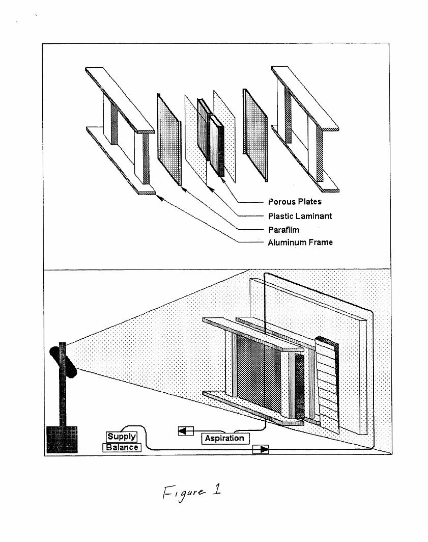
rigidity upon cooling. A schematic of the test
chamber is given in Figure 1.
Two types of porous plates were examined:
volcanic tuff and an analog material consisting
of sintered glass beads. The tuff plates (14.0
cm x 10.2 cm x 2.5 cm/plate) were cut from ablock of Timber Mountain Tuff collected near
Rainier Mesa on the Nevada Test Site.
Petrographic inspection of the tuff identified it
to be a partially welded and devitrified, high
silica rhyolite with i0_ phenocrysts of sanadine.Secondary calcite is found dispersed through the
rock and likely affects the permeability. A
porosity of 0.27 was measured gravimetrically ona small core of the tuff.
The analog porous media provides a chemicallyinert system manufactured to hydraulic
specification, which can be cleaned and reused.
Fabrication of the analog plates involves
homogeneously packing IB glass (soda-lime) beads
into a graphite mold with inner dimensions of15.2 cmx 10.2 cmx 0.8 cm. The plates are then
fired in a nitrogen atmosphere furnace. The
plates used in this experiment had a pre-
sintering bead size distribution of 0.15 to 0.21
mm and were fired at 656°C for 696 min. The
porosity of both plates was measured by
gravimetric means to be approximately 0.30.
During the experiment, constant pressure boundaryconditions were maintained around the edge of the
slab to allow air to escape. The experiment was
started by supplying a steady flow of potassiumiodide (KI) solution (10% by weight) to the topof the vertical fracture. The solution was
pumped at a constant rate of 1.7 ml/min through a
25 gauge needle inserted into a i mm I.D.capillary tube which was centered over the top ofthe fracture. KI was used to increase the x-ray
! absorption of the wetting solution and henceimprove image contrast. A light suction imposed
J by aspiration was applied at the bottom of the| fracture to prevent the build-up of fluid along
J the lower boundary. Thus the experimentsimulated the top of a much longer fracture°
| matrix system. _"
¢
Moisture content fields were captured _incrementally in time during the transient waterimbibition phase of the experiment using the x-
ray adsorption method developed by Tidwell andGlass. Is X-ray sensitive film (Kodak Industrial
AA sheet film) was placed on the back of thefracture-matrix slab and exposed by an industrial
x-ray unit set at 60 kilovolts and 18 miliamps(I00 sec for tuff, 60 sec for analog to achieve
optimum contrast).
Following complete saturation of the fracture-
matrix system, the injection solution was
switched to pure deionized water (Del). A series
of exposures were taken to explore the flushingof the KI solution from the fracture-matrix
system. This component of the experiment was
designed to demonstrate the capabilities of the
x-ray absorption technique to image transientsolute concentration fields.
Once the x-ray film was developed, a 512 x 512
array CCD camera and IBM 486 PC-based frame
grabber were used to digitize the radiograph at256 grey-levels of resolution. Using step-wedgeinformation appearing in each image, data were
adjusted for minor systematic variations in field
strengths, film, and equipment characteristics. 15
X-ray absorption theory was used to convert eachof the 262,144 data points within thetwo-dimensional field into saturation values. Is
R.ESULTS AND DISCUSSION
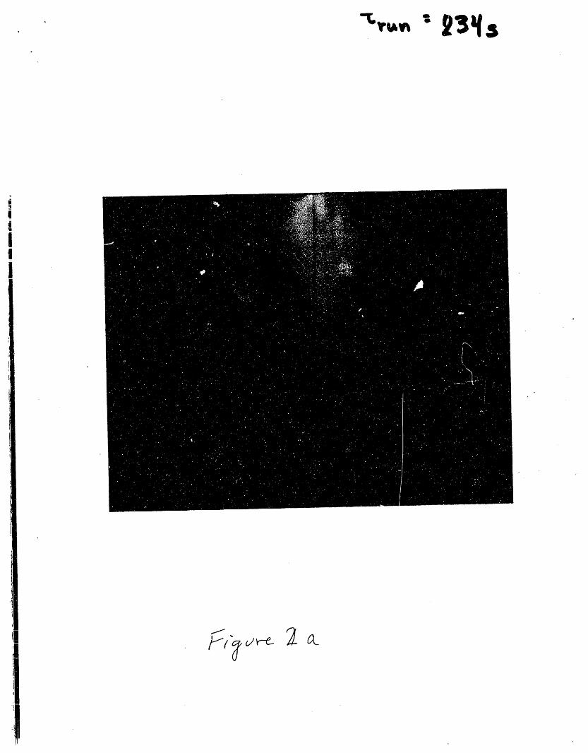
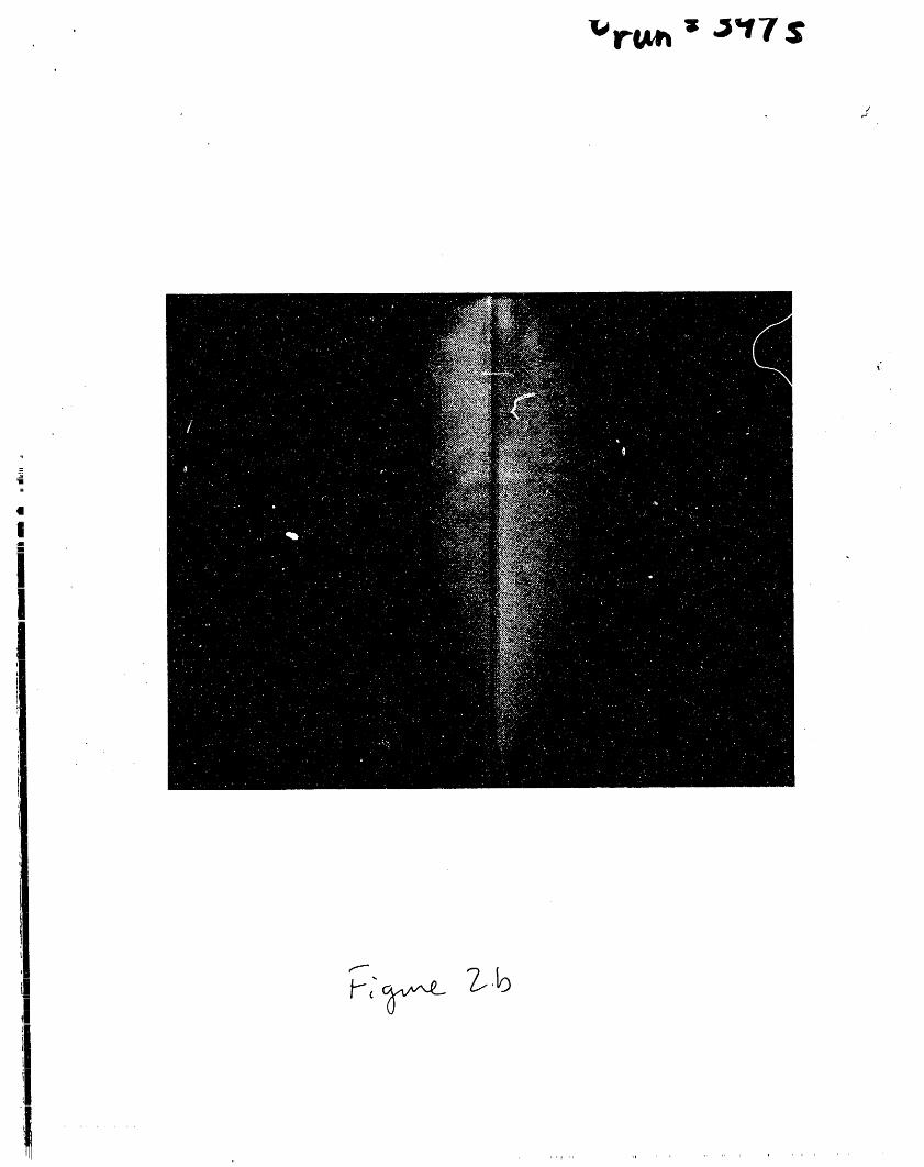
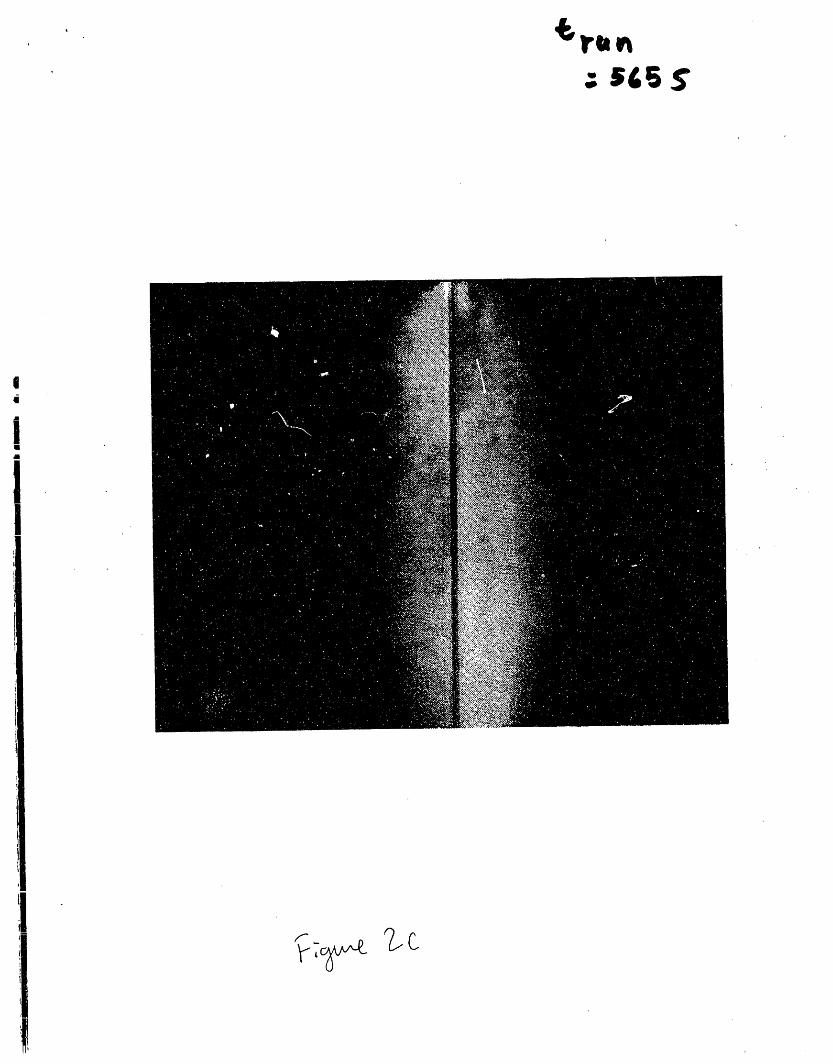
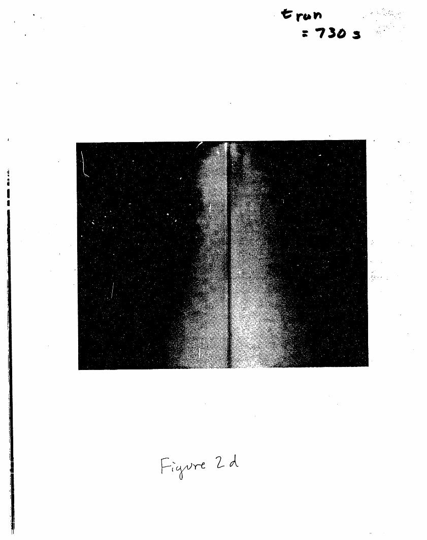
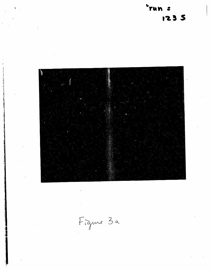
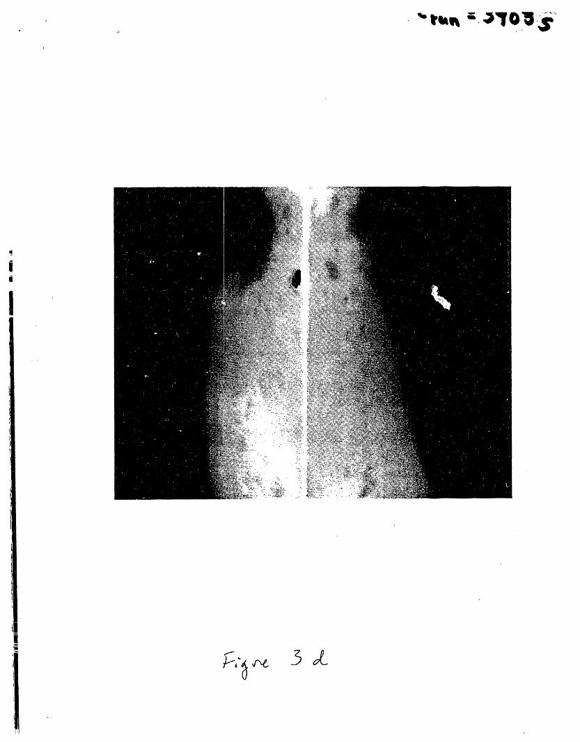
Figures 2 and 3 show a sequence of saturation
images for the analog and tuff fracture-matrix
systems, respectively. In these images, whitesignifies 100% saturation grading to black
corresponding to initial saturation (oven dry).lt should be noted that the measurement technique
has impacted the results shown here in two ways.First, saturation levels reported for thefracture are an artifact of the measurement
technique. This effect is in part due todifficulties in imaging the fluid in the fracture
while maintaining suitable contrast within thematrix. Difficulties in achieving precise
registration of images, required when converting
grey-level to saturation, is also to blame.However, image registration is a problem only
when significant contrast differences existacross very fine structure such as a fracture.Influence of the experimental technique can also
been seen in the increased widening of the wetted
region as the lower boundary of the matrix is
| approached.
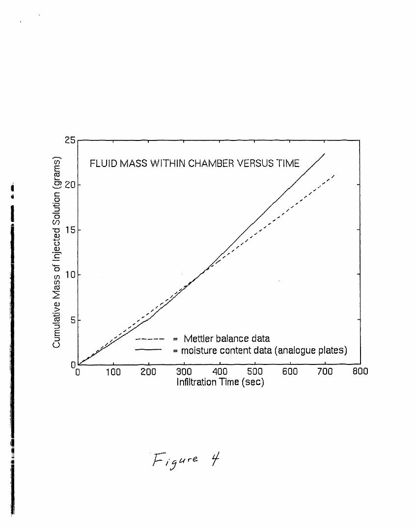
The imaging technique was evaluated by comparingthe mass of solution introduced into the test
I system with that calculated from the saturation
images. Only the mass of fluid pumped into thesystem was measured, hence comparisons must be
l drawn for images taken prior to breakthrough atthe bottom of the fracture. In the tuff system
breakthrough occurred almost immediately;therefore, comparison was only possible for the
analog system. Figure 4 shows that reference andcalculated volumes within the system agree
closely.
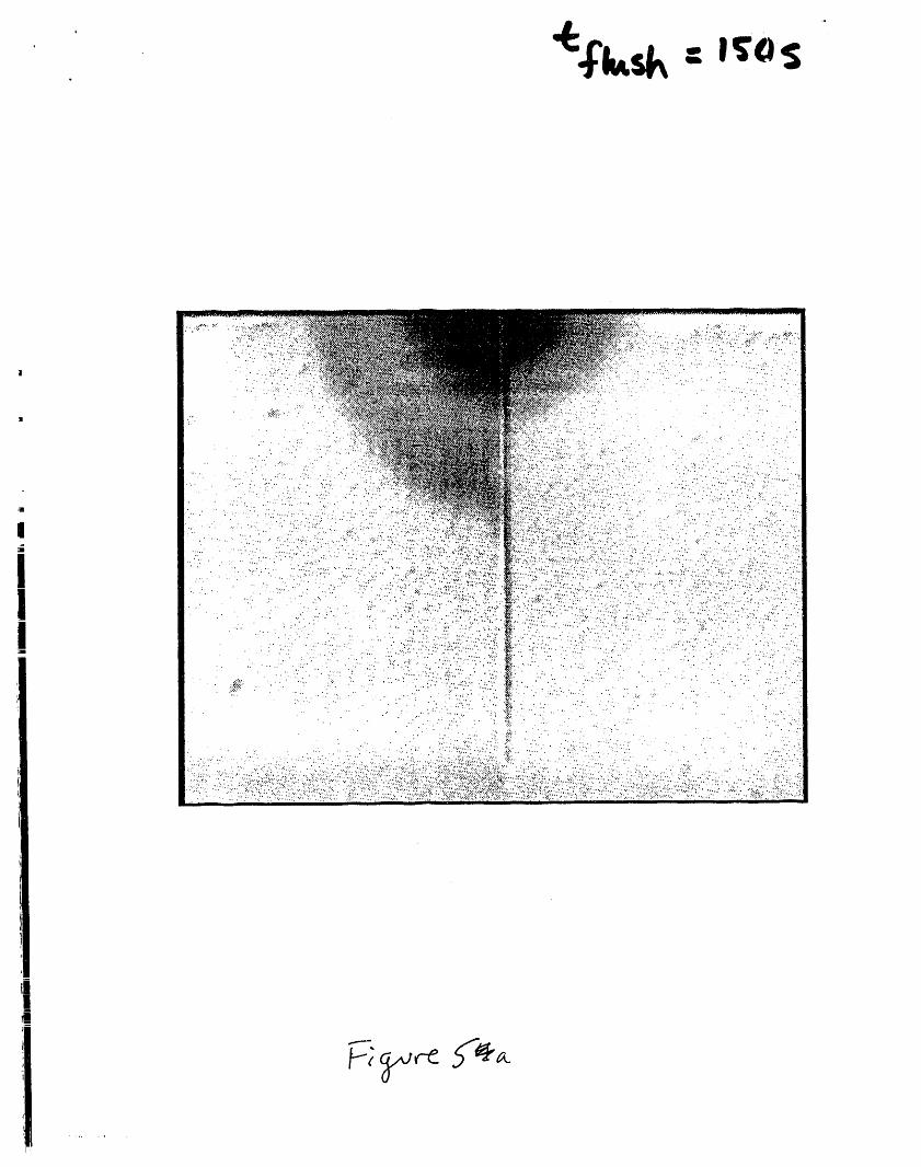
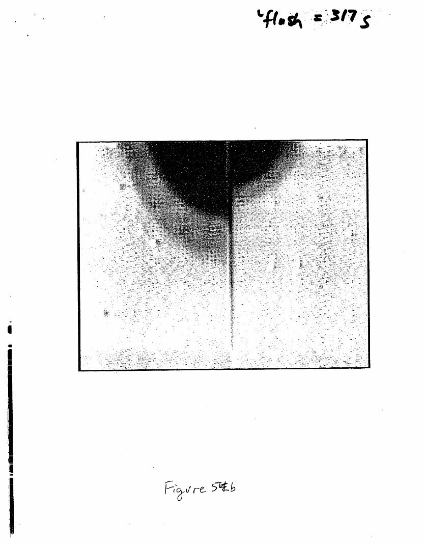
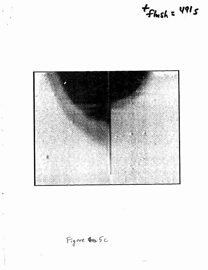
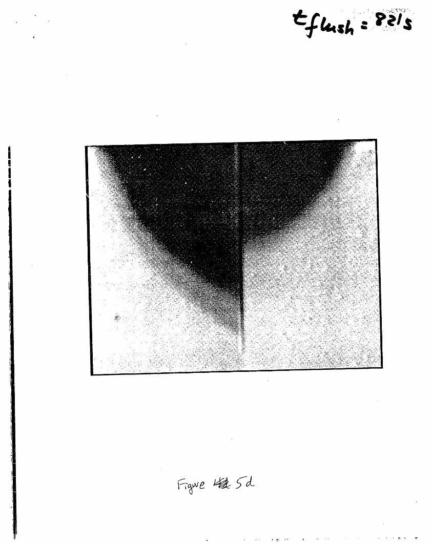
Images of the solute concentration fields for thesaturated analog system are shown in Figure 5.
In these four images the grey scale qualitativelyreferences solute concentration, with white
signifying a concentration of 10% KI, while blackcorresponds to pure Del. The shape of thesefields as well as the sharp contrast in
concentration suggest that displacement of the KI
solution in the analog material was advectively
driven. Dispersion evident in these images is
primary an artifact of the integration of theposition of the transient solute front over the
60 sec exposure time. A very different responsewas noted in the case of the tuff system where
very slow matrix diffusion was the dominant
transport process. Images of the solute
concentration fields showed no change from the
initial state for the 60 minutes that the solute
transport field was monitored and hence are notshown here.
Although similar boundary conditions and fracture
characteristics were maintained, significanti
differences between the transient flow fields in
the analog and tuff systems were observed. Themost notable difference was the dominance of
matrix flow in the analog system while fracture
flow dominated in the tuff system. Matrix
dominated flow in the analog material was induced
by a number of factors. First, capillary forces
in the matrix were sufficient to prevent the
fracture from saturating until late in the
experiment when the matrix approached full
| saturation. Once the fluid was imbibed by the
matrix (near the top of the fracture),
I gravitational forces predominated directing theflow vertically in the matrix. Matrix flow was
" further aided by high permeability which was
sufficient, under the i,nposed flux, to conduct
the imbibed fluid entirely within the matrix.
Although capillary forces of the tuff were
stronger than for the analog, low matrix
permeability of the tuff prevented substantial
imbibition thus fracture flow predominated.
Hydraulic properties of the sample were not
measured, but given that permeabilities measured
for similar tuff materials are generally low and
that the analog material can be characterized as
having a very open pore structure (due to the
narrow grain size distribution, the size of the
beads used, and short sintering time) significant
differences in permeability are expected.
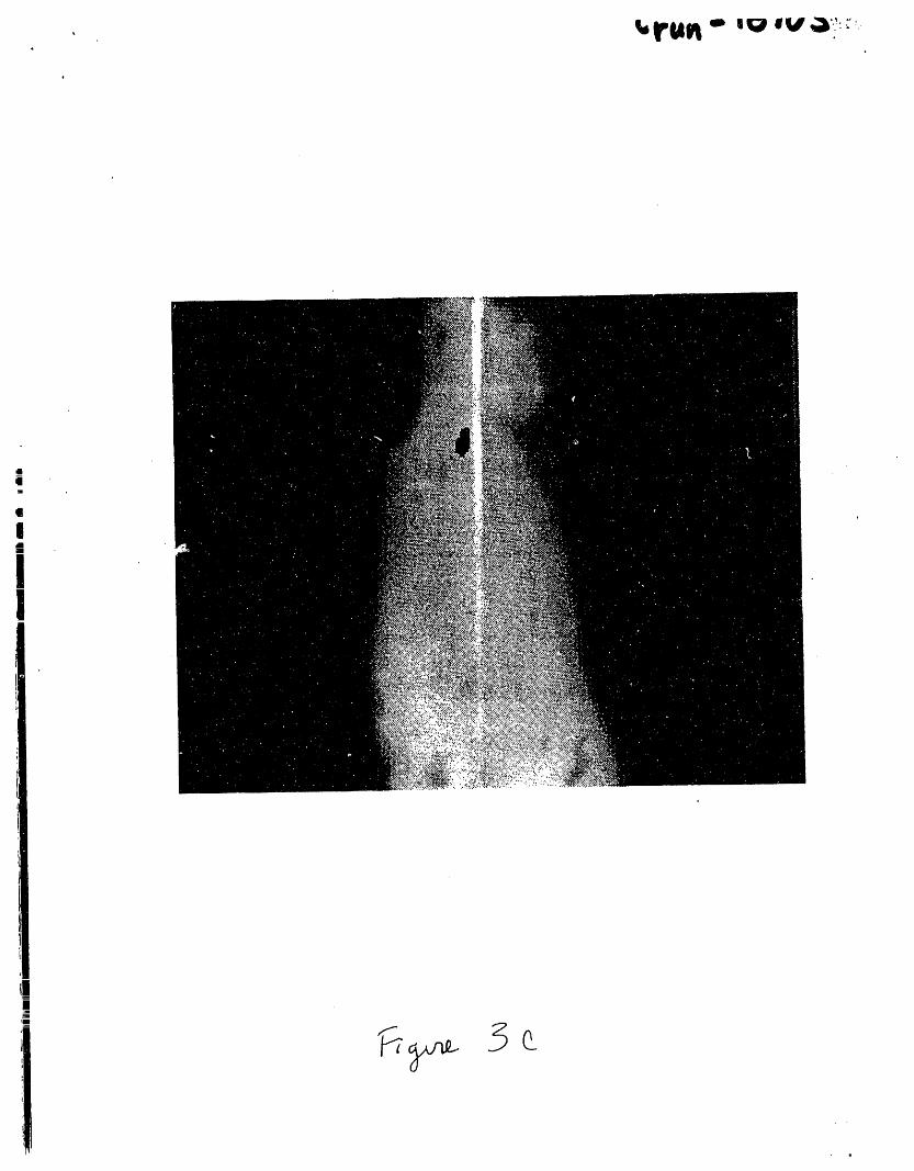
Heterogeneities had a pronounced effect on the
flow field within both the tuff and analog
systems. If the tuff system were homogeneous,
the wetting front would have moved into the
matrix essentially as a vertical front (parallel
to the fracture) because the fluid in the
fracture was maintained at near atmospheric
pressure throughout the experiment. This clearly
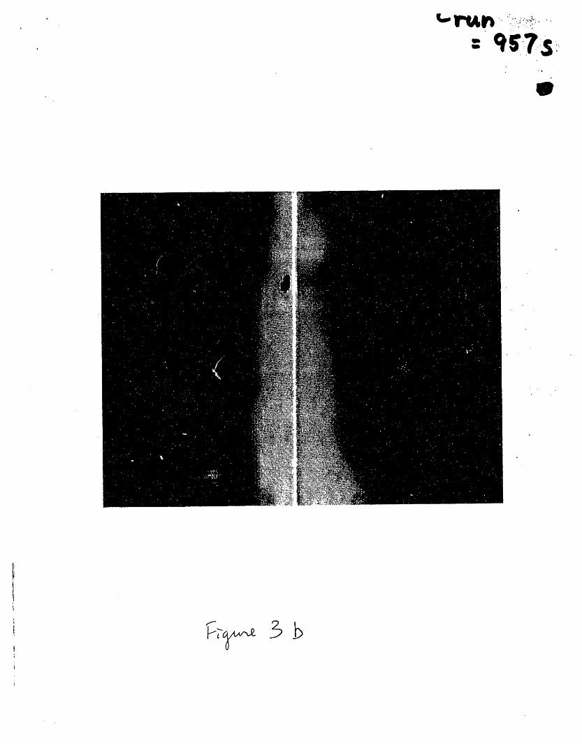
was not the case. Figure 3 shows the effect of
two pumice nodules (upper part of image on either
side of the fracture) containing large pores to
slow flow and increase tortuosity under these
unsaturated conditions. While this system
response is expected, it points out the
difference with saturated systems where such a
nodule would constitute a high conductivitymaterial.
The analog system exhibits asymmetry about thefracture plane for both the imbibition and
saturated solute transport tests. During theimbibition phase, higher imbibition into the
right side plate occurred indicating slightly
greater capillary forces and thus smaller poresin the right plate. With solute transport, theright dispersion front was retarded relative to
the left, again indicating smaller pores in the
right plate. Within each analog plate, however,both saturation and solute concentration fields
indicate homogeneity.
MODEL VALIDATION EXERCISE
Saturation and solute concentration fields
measured in our experiments can be used to test
model validity. Here we perform a simple testwith the water imbibition data from the tuff
experiment to demonstrate the validity ofRichard's equation for horizontal imbibition into
a dry tuff matrix from a saturated fracture.This simple validation test can be carried out
without approximate analytical theory, detailedproperty data, or complicated numerical code in
the following way.
Richards e equation for horizontal flow may bewritten
8_ a a8a--t" = a'-_"D(8)'_'-z (1)
with boundary and initial conditions
x t=0 0=8i
x=0 t>0 0=0o (2)
x t>0 8-8 i
Where D(8) is the water diffusivity of the media.Equation (I) with (2) allow transformation to the
non-linear ordinary differential equation
de d de2 d-_- d-_D(8)-E_ (3)
with the boundary conditions
f-O O-Oo
0-O i (4)
where f is the Boltzmann similarity variablegiven by x/t % .
Even though (3) is non-linear, solutions to (3)
with (4) for 0 are dependent only on f regardlessof the functional form of D(0). To show that
this equation provides an adequate model ofsystem behavior, any given moisture value must
propagate through the media with t% dependence.Such dependence is shown to be the case for the
tuff experiment by means of the following twoanalyses.
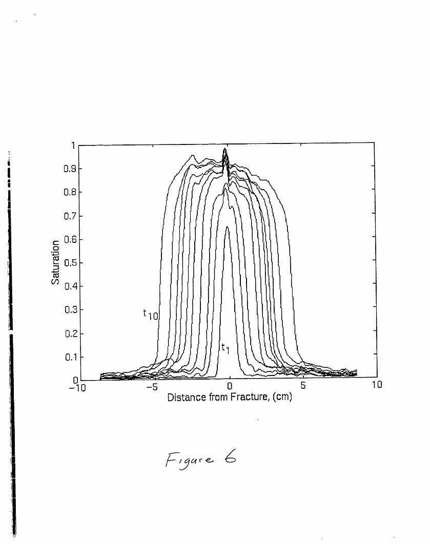
Figure 6 shows a time series of saturation
profiles taken normal to the fracture 9 cm below
the top of the tuff fracture-matrix system.
Values are averages of a moving window Ii pixelshigh and 5 pixels wide. A value of saturation of
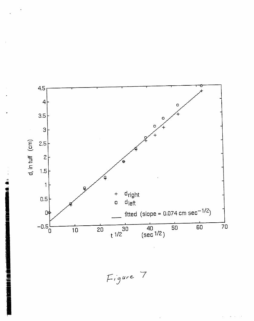
0.5 was chosen and the distance (d) from the
fracture was determined from each profile. Aplot of d versus t% is found to be linear with
small scatter as shown in figure 7. The slope ofthis line is simply f(0.5) (i.e., the Boltzmann
similarity variable for a saturation of 0.5).
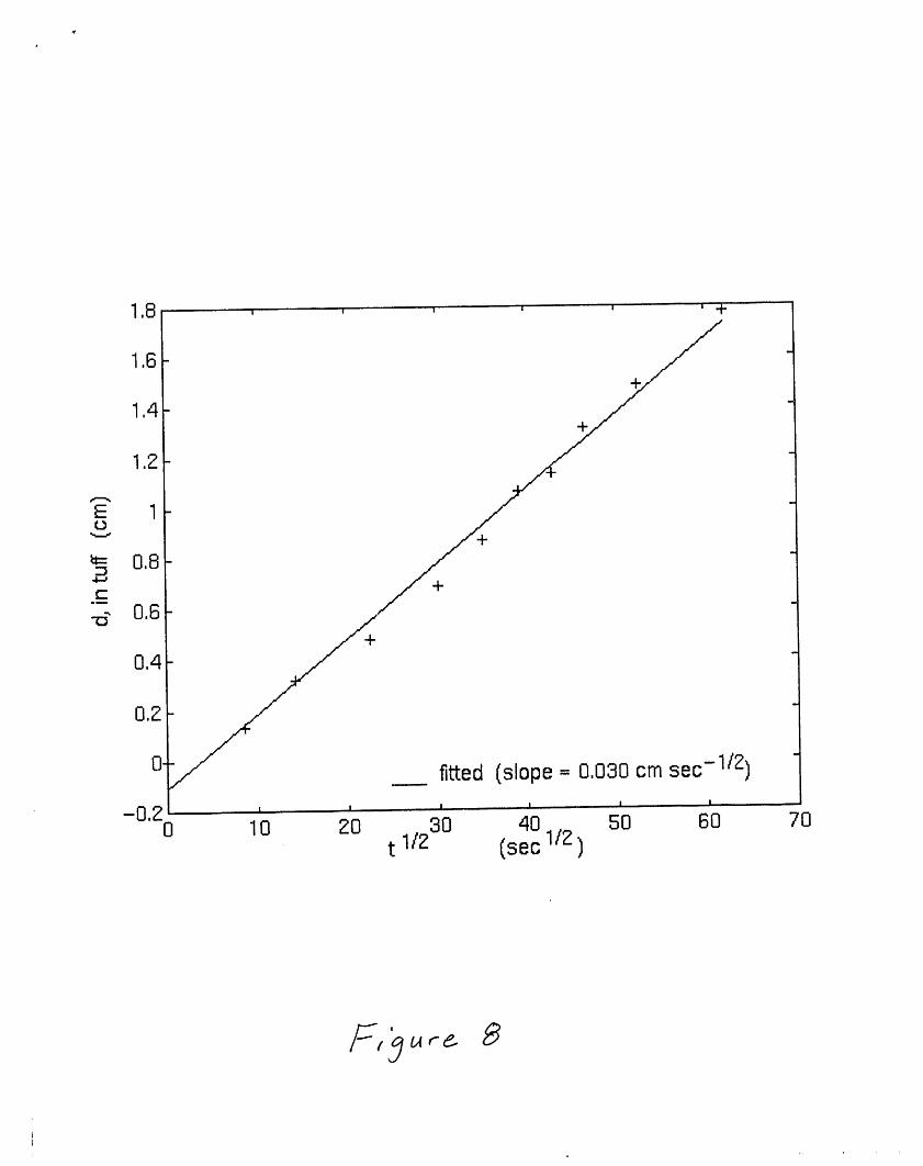
Another check on the t% dependence is to
calculate the total volume of water per unitcross-section of fracture in time as it too will
show t% dependence. The total volume infiltrated
per cross-sectional area of fracture (I), is
determined for the same region by simplyintegrating over each of the profiles in the timeseries. Figure 8 shows a plot of I versus t%
also to be linear. Half the slope of this line(because it is the combined effect of both sides
of the fracture) is the sorptivity of the media
which is the single media property required tomodel the total volume inflow and the imbibitionrate from the fracture into the matrix, lt must
be noted that the sorptivity is defined as afunction of boundary and initial conditions and
applies within the context of equations (3) and(4).
This simple test serves as an example ofvalidation for a subprocess of the fracture-
matrix system; however, it has been accomplishedfor only one of a myriad of combinations of
system parameters, initial conditions and
boundary conditions. Proper validation will
require additional physical experiments and
numerical analysis to be performed in which key
system parameters are systematically varied andmeasured, within the bounds encountered in the
natural system, to evaluate their effect on
system response. As a step in this direction, we
are in the process of comparing numerical
simulation to our experimental data.
We must note that numerous other sub-processes
governing fracture-matrix interaction that
operate both in the plane and normal to the planeof the fracture _°I°'11'Iz'13'14 must be explored
before large-scale effective media models that
| include fracture-matrix interaction may be
| adequately assessed.
CONCLUSION
Two preliminary experiments were conducted which
provide insight into the processes governingfracture-matrix interaction in the plane normal
to the fracture. Through these experiments we
demonstrated the ability of the full-field x-ray
absorption technique to acquire two-dimensionalsaturation and solute concentration fields in
heterogeneous fractured media. Further
improvement of the x-ray imaging technique is
being pursued that will greatly enhance
experimental capabilities. For instance, the use
of medical angiography x-ray equipment is being
explored. This equipment may be capable of
bringing about a two- or three-fold increase intime resolution, as well as provide enhanced
fracture imaging capabilities. The x-ray
absorption technique also shows promise as a
means of measuring porosity and sorptivity
characteristics of heterogeneous media at high
spatial resolution.
While Richard's equation was found to be a valid
means of modeling matrix imbibition from a
fracture for the discrete set of system
parameters, boundary conditions and initialconditions used in the tuff experiment, such a
simple test does not constitute model validation
for ali systems and boundary conditions. Thiswork demonstrates both the need for and the
capability to conduct systematic physical and
numerical experimentation aimed at developing
models for quantifying fracture-matrixinteraction.
li_ ACKNOWLEDGMENTSThe authors' extend their appreciation to Chris
Rautman for his help in measuring sample
porosities, David Broxton for his petrographicdescription of our tuff sample, Kerim Martinezand Craig Ginn for their help in flow chamberfabrication, Lee Orear for help in coding various
analysis tools, and Deanna Sevier for her help in
acquiring the x-ray images. This work was
supported by the U.S. Department of Energy,Office of Civilian Radioactive Waste Management,
Yucca Mountain Site Characterization Project,under contract DE-AC4-76DP00789.
REFERENCES
i. R. R. PETERS and E. A. KLAVETTER, "A
Continuum Model for Water Movement in an
Unsaturated Fractured Rock Mass," Water Resources
Research, 24, 416-430 (1988).
2. I. NERETNIEKS, and A. RASMUSON, "An approach
to modeling radionuclide migration in a medium
with strongly varying velocity and block sizesalone the flow path" Water Resources Research,
i 20, 1823-1836 (1984).
i 3. R. W. ZIMMERMAN, G. S. BODVARSSON, and E. M.
KWICKLIS, " Absorption of Water into Porous
Blocks of Various Shapes and Sizes," WaterResources Research,26,.2797-2806 (1990).
I 4. M. J. MARTINEZ, "Capillary Driven Flow in aI Fracture Located in a Porous Medium,"
SAND84-1697, Sandia National Laboratory (1988).
5. T. A. BUSCHECK and J. J. NITAO, "Estimates of
the Width of the Wetting Zone Along a Fracture
Subjected to an Episodic Infiltration Event in
Variably Saturated, Densely Welded Tuff,"UCID-2157900, Lawrence Livermore National
Laboratory (1988).
6. R. J. GLASS, "Laboratory Research Program to
Aid in Developing and Testing the Validity of
Conceptual Models for Flow and Transport ThroughUnsaturated Porous Media," Proceedings of the
Geoval'90 Symposium, Stockholm, Sweden (1989).
7. R. J. GLASS and V. C. TIDWELL, "Research
Program to Develop and Validate Conceptual Models
for Flow and Transport Through Unsaturated,Fractured Rock," in Proceedings of the Second
Annual International High Level Radioactive Waste
Management Conference, Las Vegas, 2, 977-987
(1991).
8. A. J. RUSSO and D. C. REDA, "Drying of and
Initially Saturated Fractured Volcanic Tuff,"Journal of Fluids Engineering, 3, 191-196 (1989).
9. R. J. GLASS, and D. L. NORTON, "Wetted-RegionStructure in Horizontal Unsaturated Fractures:
Water Entry Through the Surrounding PorousMatrix," in the Proceedings of the Third Annual
International High Level Radioactive Waste
Management Conference, Las Vegas, i, 717-726(1992).
I0. M. J. NICHOLL, R. J. GLASS, and H. A.
NGUYEN, "Gravity-Driven Fingering in UnsaturatedFractures," in the Proceedings of the Third
Annual International High Level Radioactive Waste
Management Conference, Las Vegas, I, 321.-331(1992).
ii. M. J. NICHOLL, R. J. CLASS, and H. A.
NGUYEN, "Wetting Front Instability in an
Initially Dry Fracture," in the Proceedings ofthe Fourth Annual International High Level
Radioactive Waste Management Conference, Las
Vegas (1993).
12. M. J. NICHOLL, R. J. GLASS, and H. A.
NGUYEN, "Small-Scale Behavior of Single Gravity-
Driven Fingers in an Initially Dry F=acture," inthe Proceedings of the Fourth Annual
International High Level Radioactive Waste
Management Conference, Las Vegas (1993).
13. D. P. GALLEGOS, S. G. THOMA, and D. M.
SMITH, "Impact of Fracture Coatings on theTransfer of Water Across Fracture Faces in
Unsaturated Media," in the Proceedings of the
Third Annual International High Level
Radioactive Waste Management Conference, Las
Vegas, I, 738-745 (1992).
14. T. C. RASMUSSEN, "Bypass Flow ThroughUnsaturated Fractured Rock: Effective Models for
Fracture-Matrix Interactions," The AGU 1992 Fall
Meeting Abstract Supplement, H32A-II (1992).
15. V. C. TIDWELL and R. J. CLASS, "X-ray and
Visible Light Transmission as Two- Dimensional,Full-Field Moisture-Sensing Techniques: A
Preliminary Comparison," in the Proceedings ofthe Third Annual International High Level
Radioactive Waste Management Conference, Las)
I[
, Vegas, I, 1099-1110 (1992).
i 16. R. J. GLASS, T. S. STEENHUIS, and J.-Y.
PARLANGE "Wetting Front Instability II'ii Experimental Determination of Relationships
Between System Parameters and Two DimensionalUnstable Flow Field Behavior in Initially Dry
Porous Media," Water Resources Research, 25,
1195-1207 (1989.
Figures"
I). Flow chamber. Above, exploded view of flow chamber assembly showing porous
plates, plastic laminant, parafilm, and aluminum frame. Below, flow chamber and
calibration step-wedge placed transversely in x-ray beam between x-ray generatorand film cassette.
2). Analog system saturation fields at a) 234, b) 397, c) 565, and d) 730 seconds.
In these images, white signifies 100% saturation grading to black corresponding to
initial saturation (oven dry). Vertical flow in the matrix is evidenced by the
uneven vertical propagation of the flow field on either side of the fracture.
3). Tuff system saturation fields at a) 123, b) 957, c) 1890, and d) 3903 seconds.
In these images, white signifies 100% saturation grading to black corresponding to
initial saturation (oven dry). Note that in the first image imbibition is evident
along the full length of the fracture indicating that the fracture transmitted
water from very early times in the experiment.
4). Comparison of the total volume of water in the a_alog system as measured by
gravimetric methods and estimated from x-ray images.
5). Analog solute concentration fields at a) 150, b) 317, c) 491, and d) 821
seconds. In these four images the grey scale qualitatively references soluteconcentration, with white signifying a concentration of 10% KI, while black
corresponds to pure Del.
6) Tuff system saturation transects for times between 123 and 3903 seconds.
7) Lateral distance from the fracture (d) where the tuff matrix has reached 50%
saturation as a function of the square root of time.-
8) Infiltration volume per cross-section of fracture (I) imbibed by tuff as a
function of the square root of time.
|
:i:i:i:i:=
,_ Porous Plates
PlasticLaminant
Parafilm
Aluminum Frame
i •I
|
.!
".": ..
5 i i i i i ,I i
"_" FLUID MASS WITHIN CHAMBERVERSUSTIME
i zo. o=
2ois
-_-,
-5 .,
,9 _" ..... = M,ettlerbalance datau ..,7. . -- moisturecontent data (analogueplates)
,i-I I , I I ,, I ....... I -
0 1O0 200 300 400 500 600 700 800InfiltrationTime (sec)
.....
F
i
45, ' ' ' ' ' ' _
4 o
3,5 oO
3+
E 2,5t,3
c"
._ 1,5
1
+ dright0,5 o dlelt
| 0_ fitted (slope = 0,074 cm sec -1/2)
-0'50 10 2:0 30 40 50 60 70t 1/2 (sec 1/2 )
,! • "-7# Ur_
oi
_r
1,13 , , ' ' ' ' +
1.6- +_ "
1,4- +,_
// -1.2-
E 1-"_ +
_ O.8-
-d 0,6
0,4
0,2:-
O, fitted (slope = 0,030 cm sec- 112)I I I I I I
-0'20 10 20 30 40 50 60 zOt IIZ (sec 11Z)
¢
I