Embed Size (px)
Citation preview
Unit 1: Introduction to DBMS
Purpose of Database Systems View of Data Database Administrator Database Users Overall System Structure Data Models Data Definition Language Data Manipulation Language
Overview
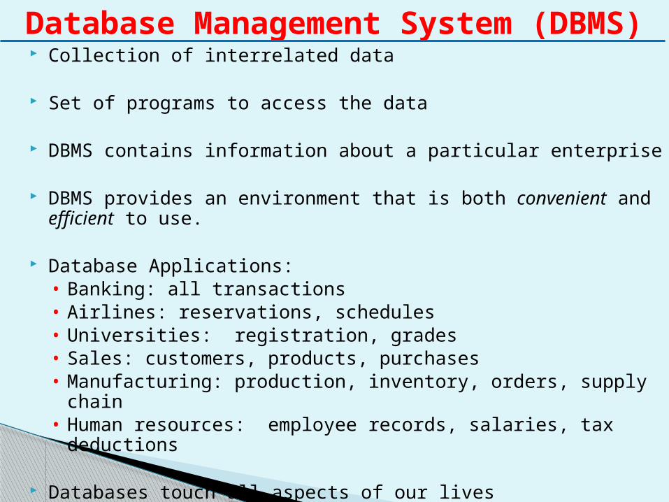
Collection of interrelated data
Set of programs to access the data
DBMS contains information about a particular enterprise
DBMS provides an environment that is both convenient and efficient to use.
Database Applications:• Banking: all transactions• Airlines: reservations, schedules• Universities: registration, grades• Sales: customers, products, purchases• Manufacturing: production, inventory, orders, supply chain• Human resources: employee records, salaries, tax deductions
Databases touch all aspects of our lives
Database Management System (DBMS)
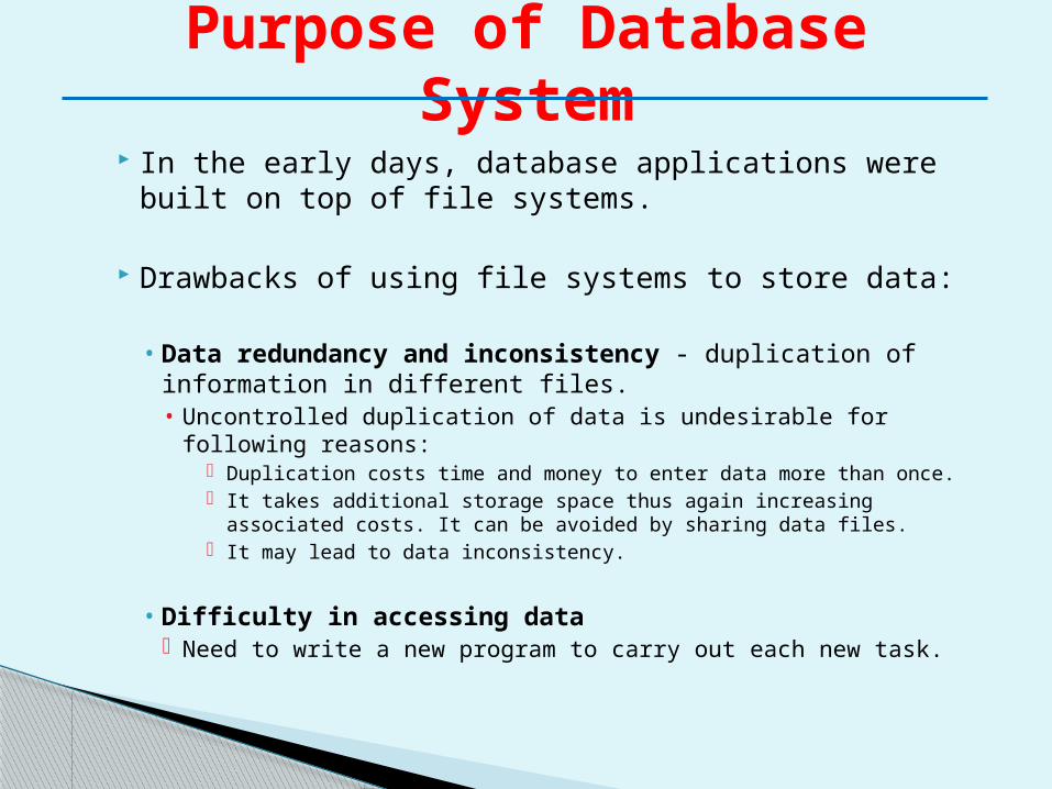
In the early days, database applications were built on top of file systems.
Drawbacks of using file systems to store data:
• Data redundancy and inconsistency - duplication of information in different files.• Uncontrolled duplication of data is undesirable for following
reasons: Duplication costs time and money to enter data more than
once. It takes additional storage space thus again increasing
associated costs. It can be avoided by sharing data files. It may lead to data inconsistency.
• Difficulty in accessing data Need to write a new program to carry out each new task.
Purpose of Database System
• Data isolation — multiple files and formats.• When data is isolated in separate files, it is more
difficult to access data and to ensure that data is correct.
• Also, the structure of file depends on application programming language. Thus the direct incompatibility of such files makes it difficult to process jointly.
• Integrity problems Integrity constraints (e.g. account balance > 0)
become part of program code Hard to add new constraints or change existing ones.
Drawbacks of file systems (cont.)
• Atomicity of updates Failures may leave database in an inconsistent state with partial
updates carried out. E.g. transfer of funds from one account to another should either
complete or not happen at all.
• Concurrent access by multiple users Concurrent accessed needed for performance. Uncontrolled concurrent accesses can lead to inconsistencies
E.g. two people reading a balance and updating it at the same time.
• Security problems
Database systems offer solutions to all the above problems
Drawbacks of file systems (cont.)
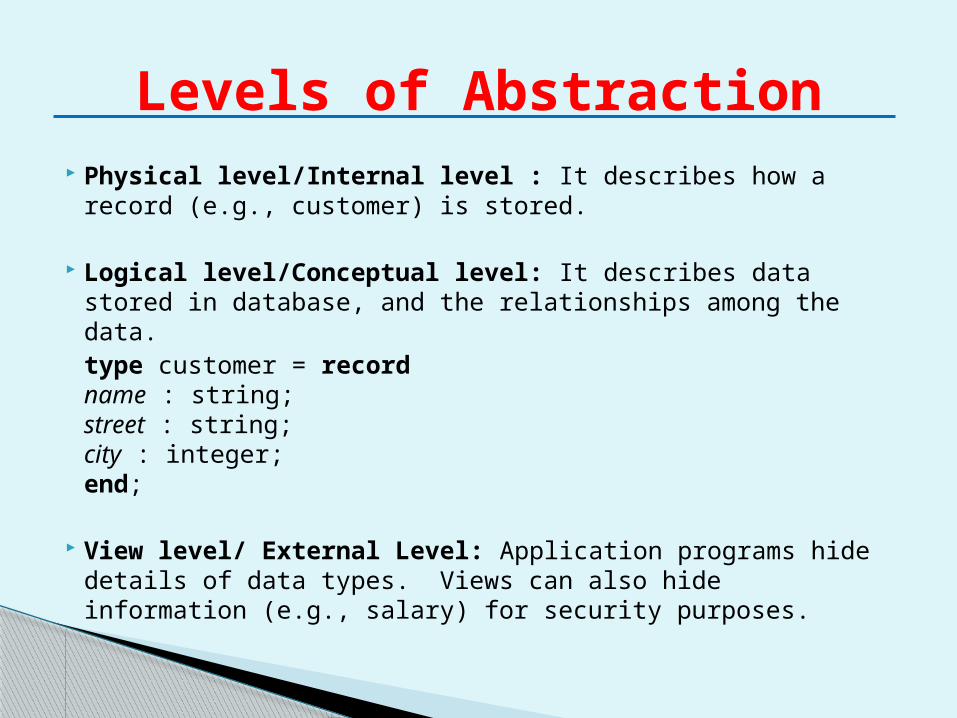
Physical level/Internal level : It describes how a record (e.g., customer) is stored.
Logical level/Conceptual level: It describes data stored in database, and the relationships among the data.
type customer = recordname : string;street : string;city : integer;
end;
View level/ External Level: Application programs hide details of data types. Views can also hide information (e.g., salary) for security purposes.
Levels of Abstraction
Views of Data
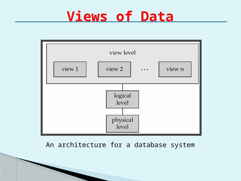
An architecture for a database system
Views of Data Physical level/Internal level : The physical
representation of the database on the computer. This level describes how the data is stored in the database.
Logical level/Conceptual level: The community view of the database. This level describes what data is stored in the database and the relationships among the data.
View level/ External Level: The users view of the database. This level describes that part of the database that is relevant to each user.
Advantages of DBMS
Control of data redundancy Data consistency More information from the same amount of data Sharing of data Improved data integrity Improved security Enforcement of standards Economy of scale Balance of conflicting requirements Improved data accessibility and responsiveness Increased productivity Improved maintenance through data
independence
Disadvantages of DBMS Complexity – provision of the functionality we
expect from DBMS makes it extremely complex. Size – complexity and breadth of functionality
makes DBMS extremely large piece of software. Cost of DBMSs – it varies significantly depending on
the environment & functionality provided. Additional hardware costs – to achieve required
performance, it is necessary to procure large memory.
Performance – DBMS is written to be more general, to cater for many applications rather than just one.
Higher impact of failure – Centralization of resources increases the vulnerability of the system. Since all users & applications rely on DBMS, the failure of one component can bring operations to a halt.
Components of the DBMS1. Hardware – DBMS and the applications require
hardware to run.• It can range from PC to mainframe or network
of computers.• It depends on the organization’s requirements
and the DBMS used.2. Software – It comprises of following :
• DBMS software itself • Application program • Operating System including network software
3. Data - Most important component from end-user’s point of view. • It acts as a bridge between the machine
components and the human component. • The database contains both operational data
and the metadata.
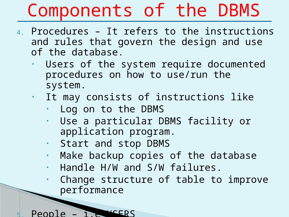
Components of the DBMS4. Procedures – It refers to the instructions and rules that
govern the design and use of the database.• Users of the system require documented procedures
on how to use/run the system.• It may consists of instructions like
• Log on to the DBMS• Use a particular DBMS facility or application
program.• Start and stop DBMS• Make backup copies of the database• Handle H/W and S/W failures.• Change structure of table to improve performance
5. People – i.e USERS
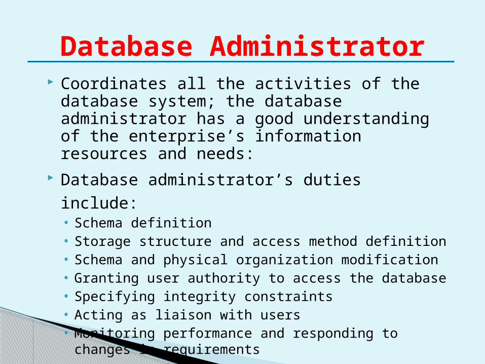
Database Administrator Coordinates all the activities of the database
system; the database administrator has a good understanding of the enterprise’s information resources and needs:
Database administrator’s duties include:• Schema definition• Storage structure and access method definition• Schema and physical organization modification• Granting user authority to access the database• Specifying integrity constraints• Acting as liaison with users• Monitoring performance and responding to changes in
requirements
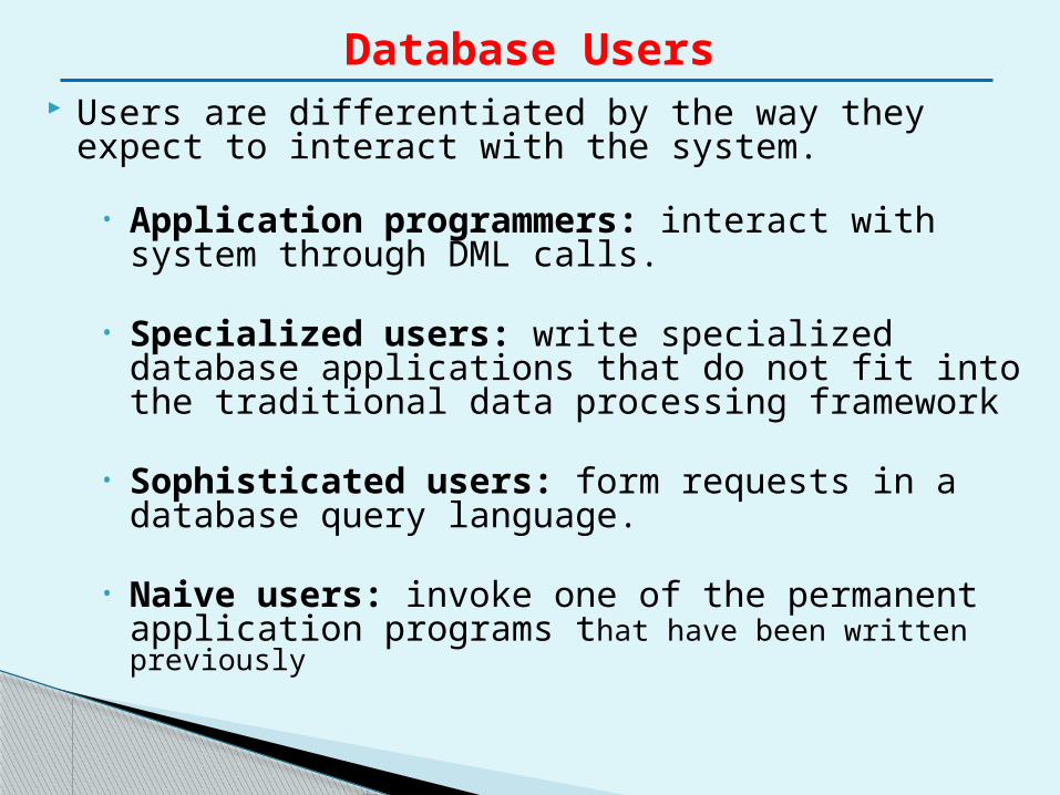
Database Users Users are differentiated by the way they expect to
interact with the system.
• Application programmers: interact with system through DML calls.
• Specialized users: write specialized database applications that do not fit into the traditional data processing framework
• Sophisticated users: form requests in a database query language.
• Naive users: invoke one of the permanent application programs that have been written previously
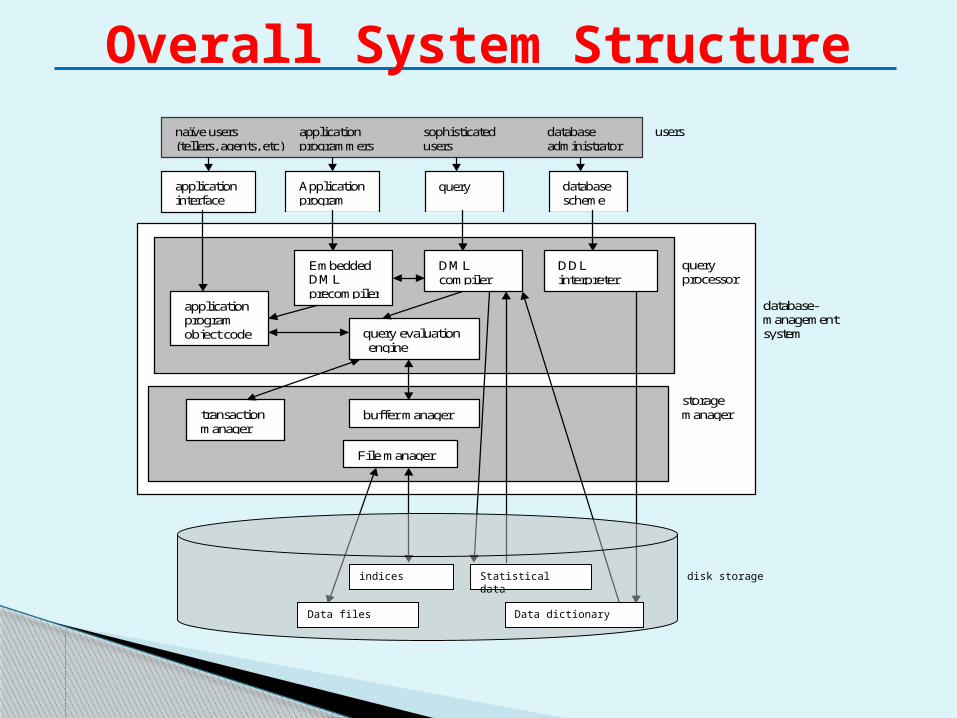
Overall System Structure naïve users application sophisticated database
(tellers, agents, etc) programmers users administrator
application interface
Application program
query database scheme
users
application program object code query evaluation
engine
Embedded DML precompiler
DML compiler
DDL interpreter
transaction manager
buffer manager
query processor
storage manager
database- management system
File manager
indices Statistical data
Data files Data dictionary
disk storage
Characteristics of Database
Self-describing nature of a database system.
Insulation between programs and data, and data abstraction.
Support of multiple views of the data.
Sharing of data and multiuser transaction processing.
Data Models An integrated collection of concepts for
describing and manipulating the following in an organization:• Data• Data relationships• Data semantics• Data constraints
A data model can be thought of as comprising 3 components:
• Structural Part – consisting of set of rules according to which databases can be structured.
• Manipulative part – defining the types of operations that are allowed on the data (includes insertion, retrieval or updating)
• Set of integrity rules – for ensuring that data is accurate.
Data Model Categories
Object-based data models◦ Entity-relationship model◦ Object-oriented model◦ Semantic model◦ Functional model
Record-based logical models◦ Relational model (e.g., SQL/DS, DB2)◦ Network model◦ Hierarchical model (e.g., IMS)
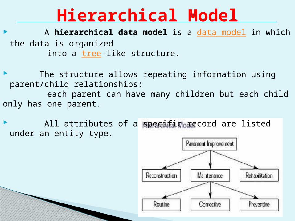
Hierarchical Model A hierarchical data model is a data model in which the data is
organized into a tree-like structure.
The structure allows repeating information using parent/child relationships:
each parent can have many children but each child only has one parent.
All attributes of a specific record are listed under an entity type.
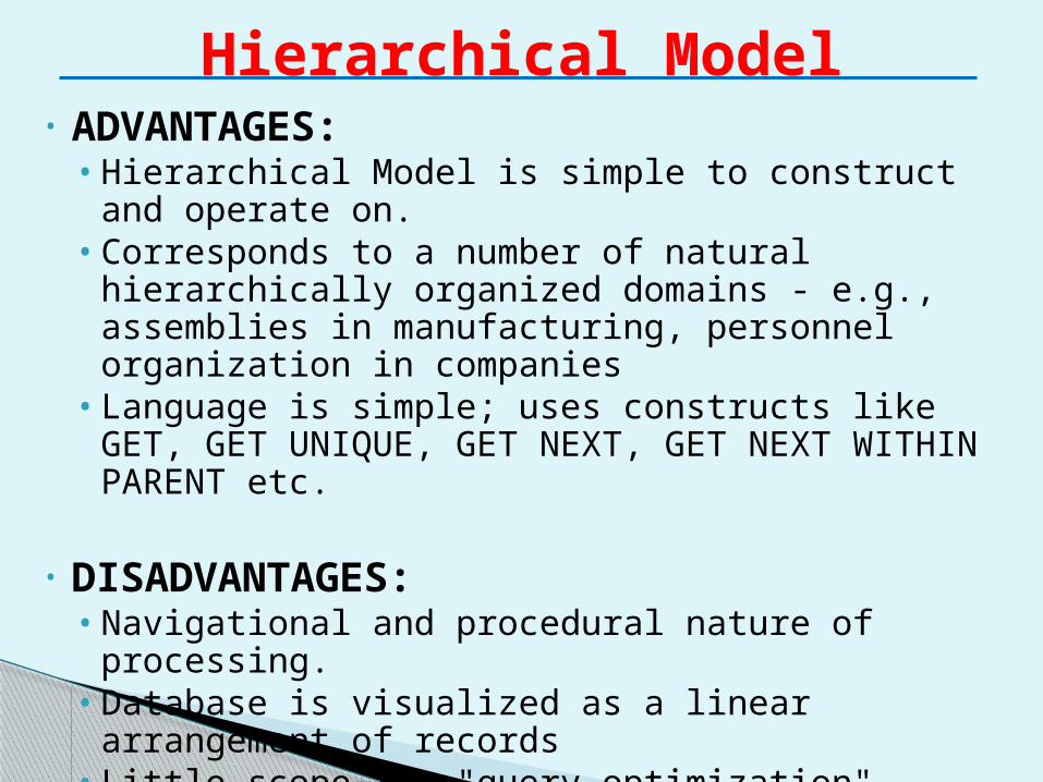
Hierarchical Model• ADVANTAGES:
• Hierarchical Model is simple to construct and operate on.
• Corresponds to a number of natural hierarchically organized domains - e.g., assemblies in manufacturing, personnel organization in companies
• Language is simple; uses constructs like GET, GET UNIQUE, GET NEXT, GET NEXT WITHIN PARENT etc.
• DISADVANTAGES:• Navigational and procedural nature of processing.• Database is visualized as a linear arrangement of
records• Little scope for "query optimization"
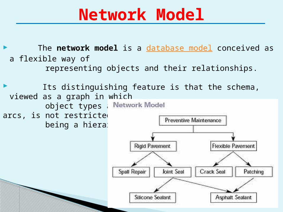
The network model is a database model conceived as a flexible way of representing objects and their relationships.
Its distinguishing feature is that the schema, viewed as a graph in which object types are nodes and relationship types are arcs, is not restricted to being a hierarchy or lattice.
Network Model
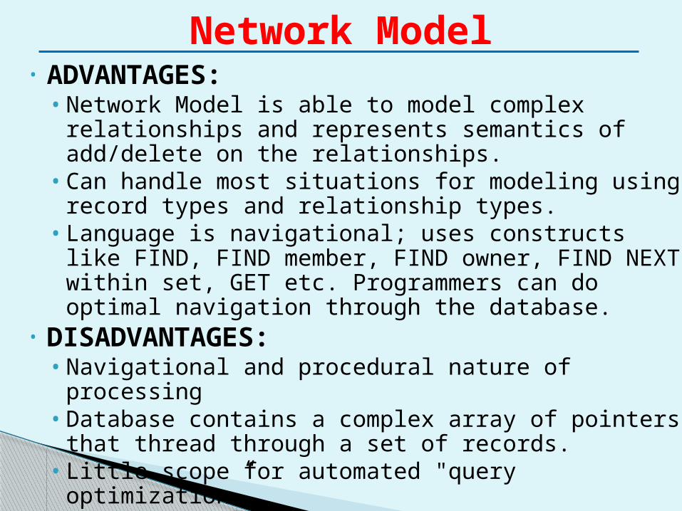
Network Model• ADVANTAGES:
• Network Model is able to model complex relationships and represents semantics of add/delete on the relationships.
• Can handle most situations for modeling using record types and relationship types.
• Language is navigational; uses constructs like FIND, FIND member, FIND owner, FIND NEXT within set, GET etc. Programmers can do optimal navigation through the database.
• DISADVANTAGES:• Navigational and procedural nature of processing• Database contains a complex array of pointers that
thread through a set of records. • Little scope for automated "query optimization”
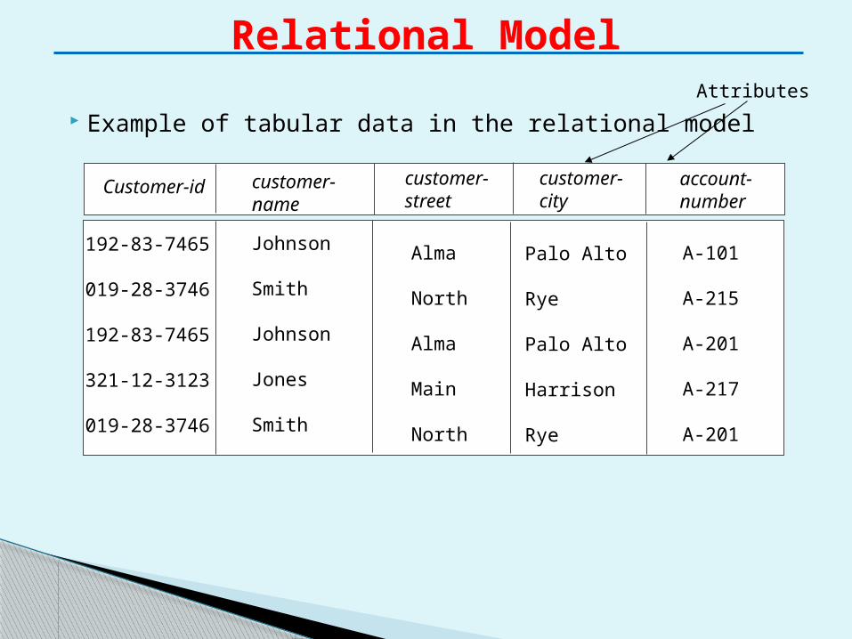
Example of tabular data in the relational model
Relational Model
customer-name
Customer-id customer-street
customer-city
account-number
Johnson
Smith
Johnson
Jones
Smith
192-83-7465
019-28-3746
192-83-7465
321-12-3123
019-28-3746
Alma
North
Alma
Main
North
Palo Alto
Rye
Palo Alto
Harrison
Rye
A-101
A-215
A-201
A-217
A-201
Attributes
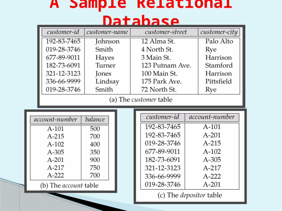
A Sample Relational Database
Instances and schemas are similar to types and variables in programming languages.
Schema – the logical structure of the database. This means overall description of the database. • e.g., the database consists of information about a set of
customers and accounts and the relationship between them.
• Analogous to type information of a variable in a program.
• Physical schema: database design at the physical level.
• Logical schema: database design at the logical level.
• The schema is specified during the database design process and is not expected to change frequently.
Schemas and Instances
Instance – the actual content of the database i.e. actual data at a particular point in time .• Analogous to the value of a variable.• The actual data in the database may change very frequently.
Thus many database instances can correspond to the same database schema.
The schema is sometimes called as intension of the database.
The instance is sometimes called as extension or state of the database.
Schemas and Instances
Three-Schema Architecture
• Defines DBMS schemas at three levels:
• Internal schema at the internal level to describe physical storage structures and access paths. Typically uses a physical data model.
• Conceptual schema at the conceptual level to describe the structure and constraints for the whole database for a community of users. Uses a conceptual or an implementation data model.
• External schemas at the external level to describe the various user views. Usually uses the same data model as the conceptual level.
Three-Schema Architecture
Mappings among schema levels are needed to transform requests and data. Programs refer to an external schema, and are mapped by the DBMS to the internal schema for execution.
Mappings between internal and conceptual schemas is known I/C mapping.
Mappings between external and conceptual schemas is known E/C mapping.
The disjointing of data descriptions from the application programs (or user-interfaces) that uses the data is called data independence.
Data independence is one of the main advantages of DBMS.
The three-schema architecture provides the concept of data independence, which means that upper-levels are unaffected by changes to lower-levels.
The interfaces between the various levels and components should be well defined so that changes in some parts do not seriously influence others.
There are two kinds of data independence.
• Physical Data Independence• Logical Data Independence
Data Independence
Physical Data Independence – the ability to modify the physical schema without changing the logical schema
• Applications depend on the logical schema• In general, the interfaces between the various levels and
components should be well defined so that changes in some parts do not seriously influence others.
Logical Data Independence – the ability to modify the conceptual schema without changing the application program
• Usually done when logical structure of database is altered.
• Logical data independence is harder to achieve as the application programs are usually heavily dependent on the logical structure of the data. An analogy is made to abstract data types in programming languages.
Types of Data Independence
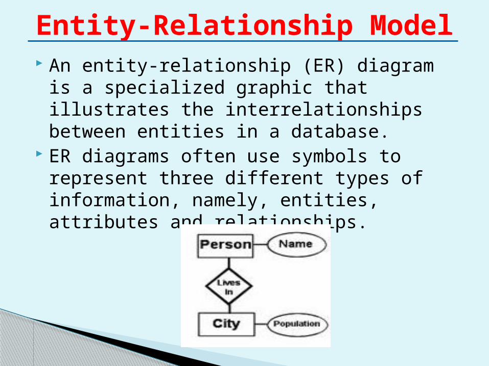
An entity-relationship (ER) diagram is a specialized graphic that illustrates the interrelationships between entities in a database.
ER diagrams often use symbols to represent three different types of information, namely, entities, attributes and relationships.
Entity-Relationship Model
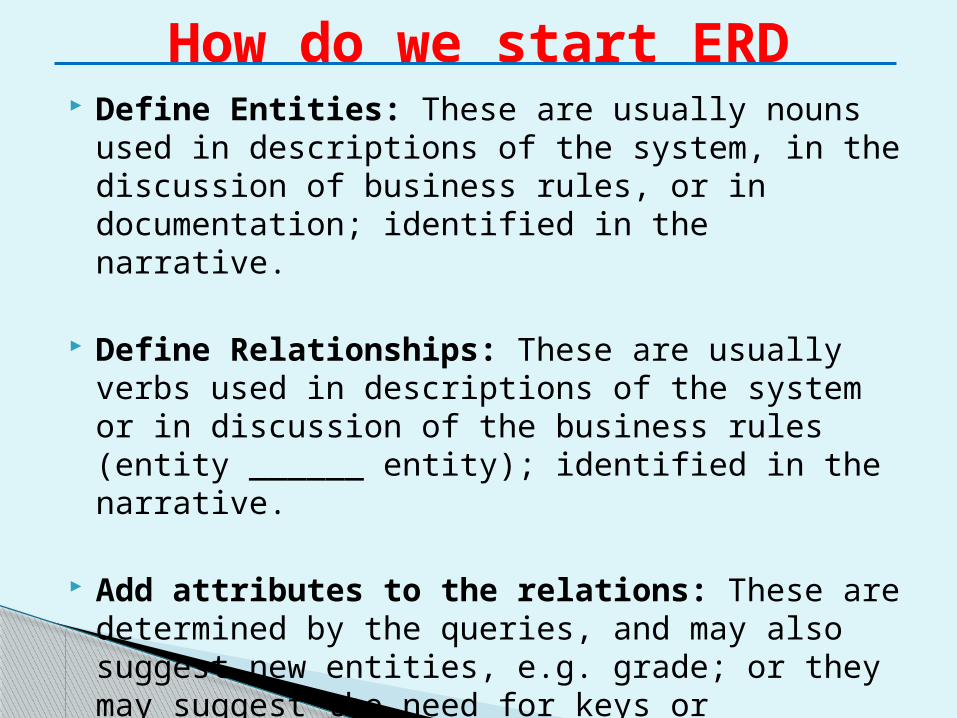
Define Entities: These are usually nouns used in descriptions of the system, in the discussion of business rules, or in documentation; identified in the narrative.
Define Relationships: These are usually verbs used in descriptions of the system or in discussion of the business rules (entity ______ entity); identified in the narrative.
Add attributes to the relations: These are determined by the queries, and may also suggest new entities, e.g. grade; or they may suggest the need for keys or identifiers.
How do we start ERD
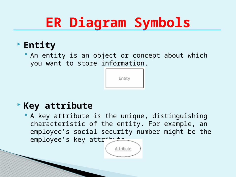
Entity An entity is an object or concept about which you want to
store information.
Key attribute A key attribute is the unique, distinguishing characteristic
of the entity. For example, an employee's social security number might be the employee's key attribute.
ER Diagram Symbols
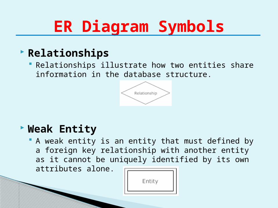
Relationships Relationships illustrate how two entities share information
in the database structure.
Weak Entity A weak entity is an entity that must defined by a foreign
key relationship with another entity as it cannot be uniquely identified by its own attributes alone.
ER Diagram Symbols
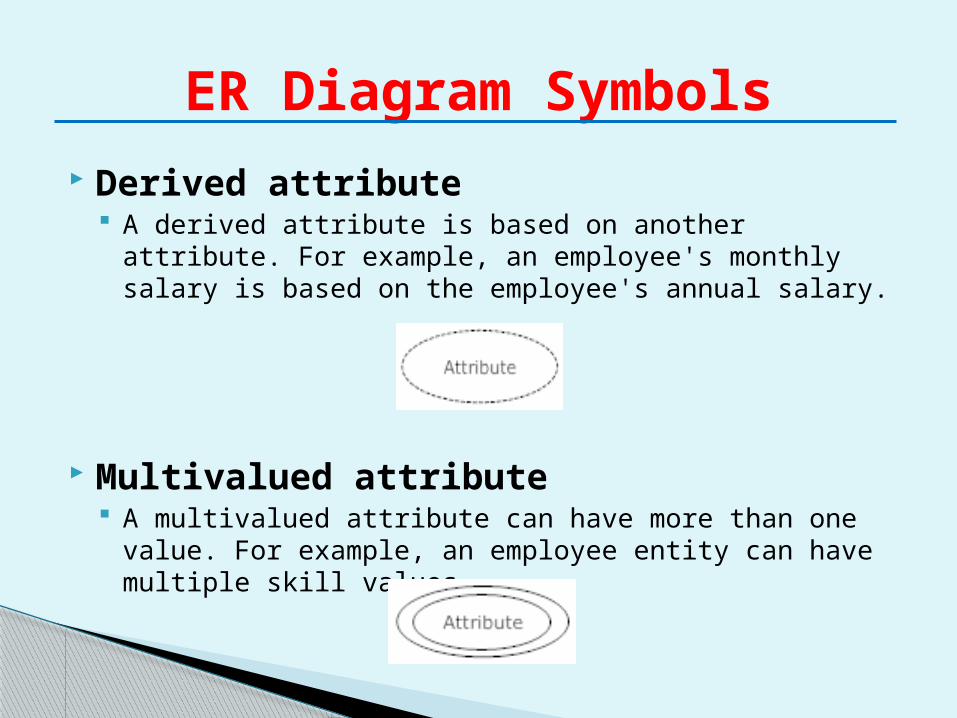
Derived attribute A derived attribute is based on another attribute. For
example, an employee's monthly salary is based on the employee's annual salary.
Multivalued attribute A multivalued attribute can have more than one value.
For example, an employee entity can have multiple skill values.
ER Diagram Symbols
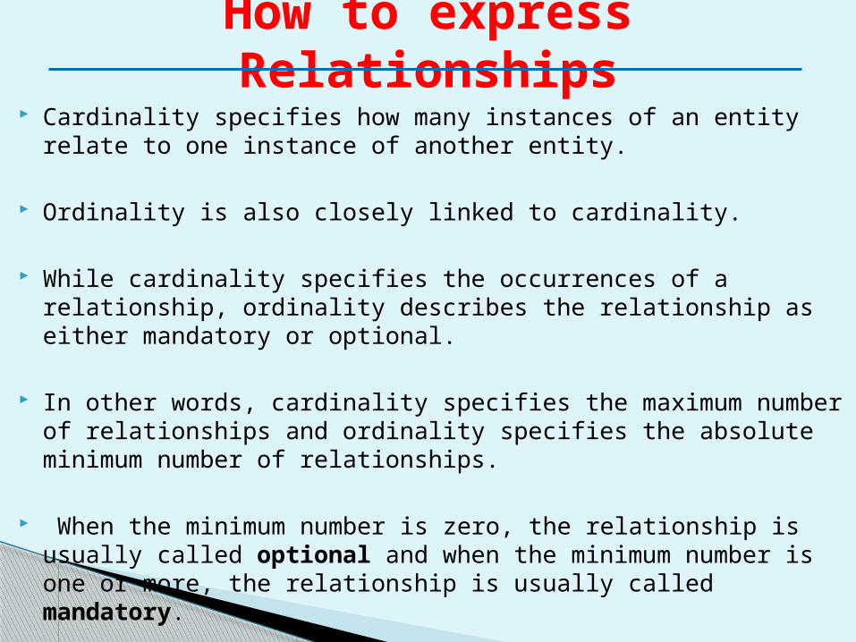
Cardinality specifies how many instances of an entity relate to one instance of another entity.
Ordinality is also closely linked to cardinality.
While cardinality specifies the occurrences of a relationship, ordinality describes the relationship as either mandatory or optional.
In other words, cardinality specifies the maximum number of relationships and ordinality specifies the absolute minimum number of relationships.
When the minimum number is zero, the relationship is usually called optional and when the minimum number is one or more, the relationship is usually called mandatory.
How to express Relationships
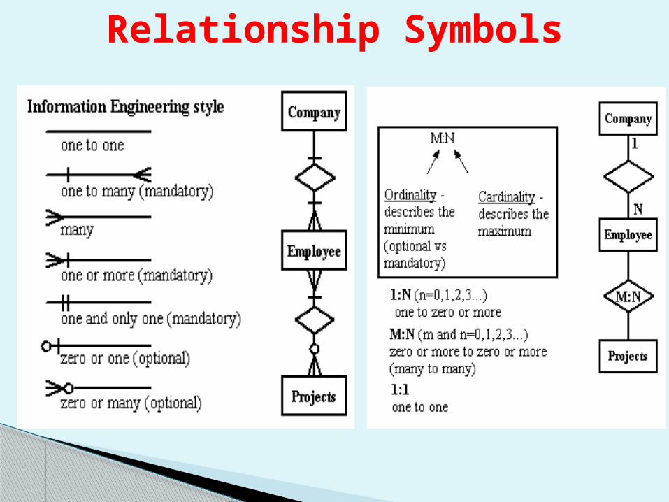
Relationship Symbols
a
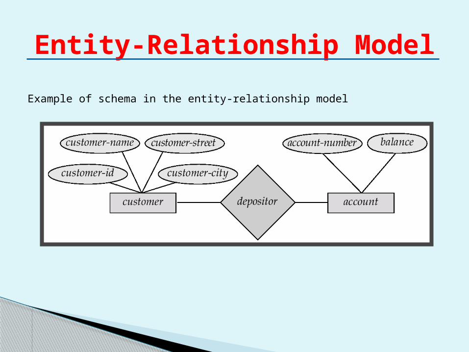
Example of schema in the entity-relationship model
Entity-Relationship Model
E-R model of real world◦ Entities (objects)
E.g. customers, accounts, bank branch◦ Relationships between entities
E.g. Account A-101 is held by customer Johnson Relationship set depositor associates customers with
accounts Widely used for database design
◦ Database design in E-R model usually converted to design in the relational model (coming up next) which is used for storage and processing
Entity Relationship Model (Cont.)
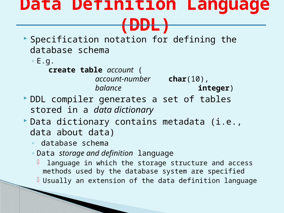
Specification notation for defining the database schema◦ E.g.
create table account ( account-number char(10), balance integer)
DDL compiler generates a set of tables stored in a data dictionary
Data dictionary contains metadata (i.e., data about data)◦ database schema ◦ Data storage and definition language
language in which the storage structure and access methods used by the database system are specified
Usually an extension of the data definition language
Data Definition Language (DDL)
Language for accessing and manipulating the data organized by the appropriate data model◦ DML also known as query language
Two classes of languages ◦ Procedural – user specifies what data is required
and how to get those data ◦ Nonprocedural – user specifies what data is
required without specifying how to get those data SQL is the most widely used query language
Data Manipulation Language (DML)
Entity-Relationship Model
Entity Sets Relationship Sets Design Issues Mapping Constraints Keys E-R Diagram Extended E-R Features Design of an E-R Database Schema Reduction of an E-R Schema to Tables
Agenda
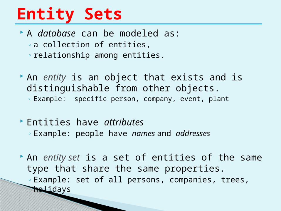
A database can be modeled as:◦ a collection of entities,◦ relationship among entities.
An entity is an object that exists and is distinguishable from other objects.◦ Example: specific person, company, event, plant
Entities have attributes◦ Example: people have names and addresses
An entity set is a set of entities of the same type that share the same properties.◦ Example: set of all persons, companies, trees, holidays
Entity Sets
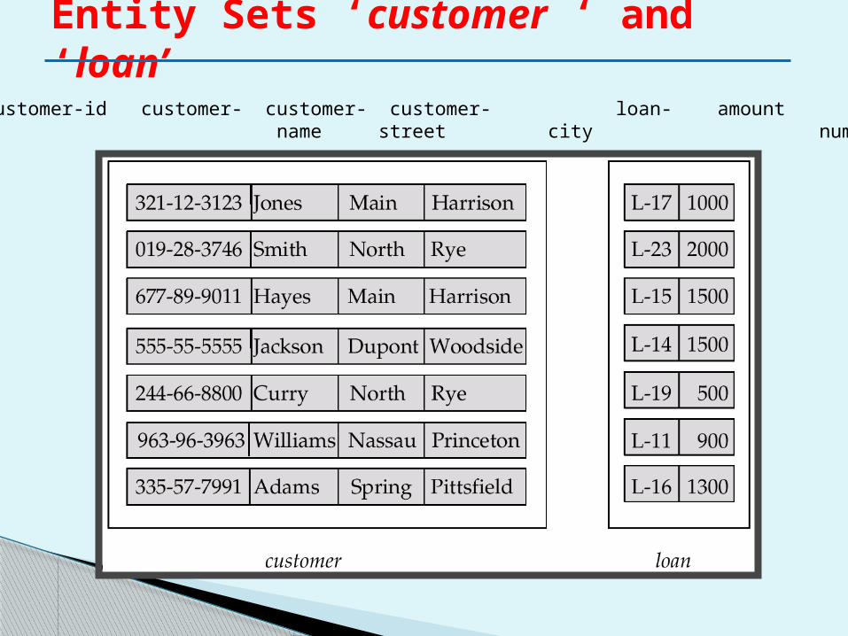
Entity Sets ‘customer ‘ and ‘loan’
customer-id customer- customer- customer- loan- amount name street city number
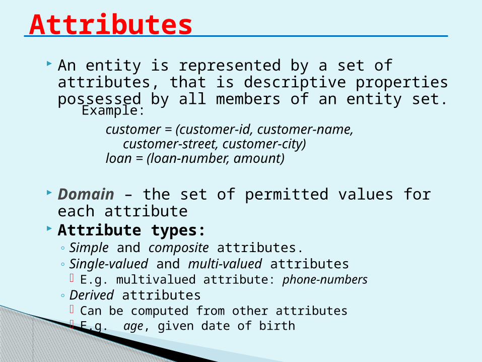
An entity is represented by a set of attributes, that is descriptive properties possessed by all members of an entity set.
Domain – the set of permitted values for each attribute
Attribute types:◦ Simple and composite attributes.◦ Single-valued and multi-valued attributes
E.g. multivalued attribute: phone-numbers◦ Derived attributes
Can be computed from other attributes E.g. age, given date of birth
Attributes
Example:
customer = (customer-id, customer-name, customer-street, customer-city)
loan = (loan-number, amount)
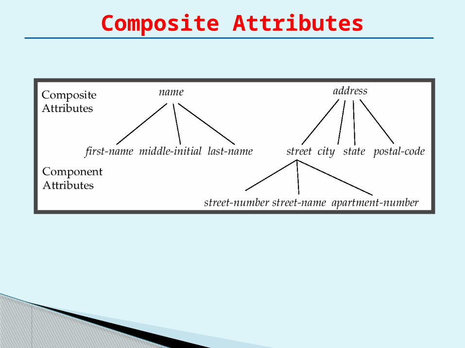
Composite Attributes
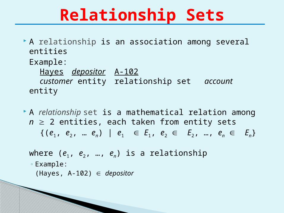
A relationship is an association among several entitiesExample:
Hayes depositor A-102customer entity relationship set account
entity
A relationship set is a mathematical relation among n 2 entities, each taken from entity sets
{(e1, e2, … en) | e1 E1, e2 E2, …, en En}
where (e1, e2, …, en) is a relationship◦ Example:
(Hayes, A-102) depositor
Relationship Sets
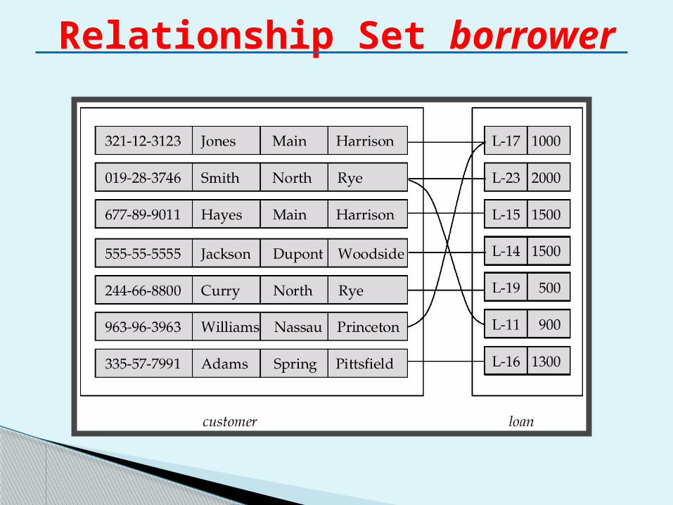
Relationship Set borrower
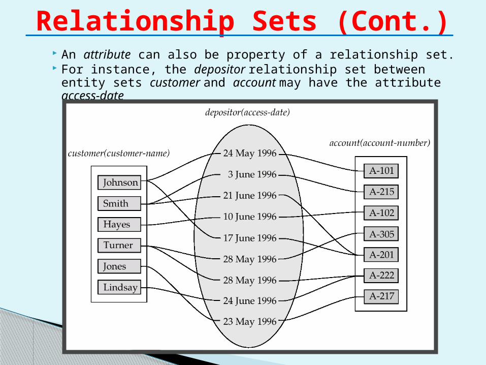
An attribute can also be property of a relationship set. For instance, the depositor relationship set between entity
sets customer and account may have the attribute access-date
Relationship Sets (Cont.)
Refers to number of entity sets that participate in a relationship set.
Relationship sets that involve two entity sets are binary (or degree two). Generally, most relationship sets in a database system are binary.
Relationship sets may involve more than two entity sets.
Relationships between more than two entity sets are rare. Most relationships are binary.
Degree of a Relationship Set
E.g. Suppose employees of a bank may have jobs (responsibilities) at multiple branches, with different jobs at different branches. Then there is a ternary relationship set between entity sets employee, job and branch
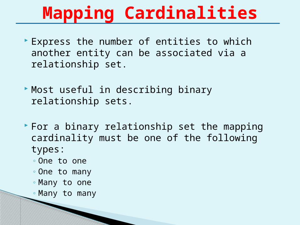
Express the number of entities to which another entity can be associated via a relationship set.
Most useful in describing binary relationship sets.
For a binary relationship set the mapping cardinality must be one of the following types:◦ One to one◦ One to many◦ Many to one◦ Many to many
Mapping Cardinalities
Mapping Cardinalities
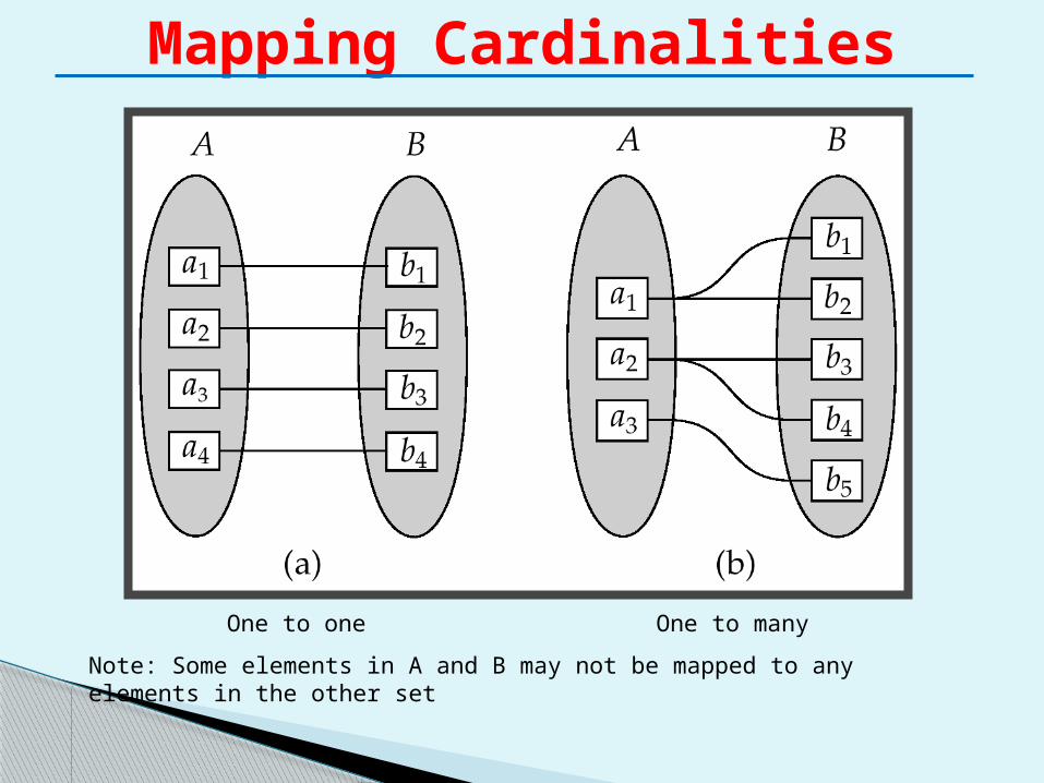
One to one One to many
Note: Some elements in A and B may not be mapped to any elements in the other set
Mapping Cardinalities
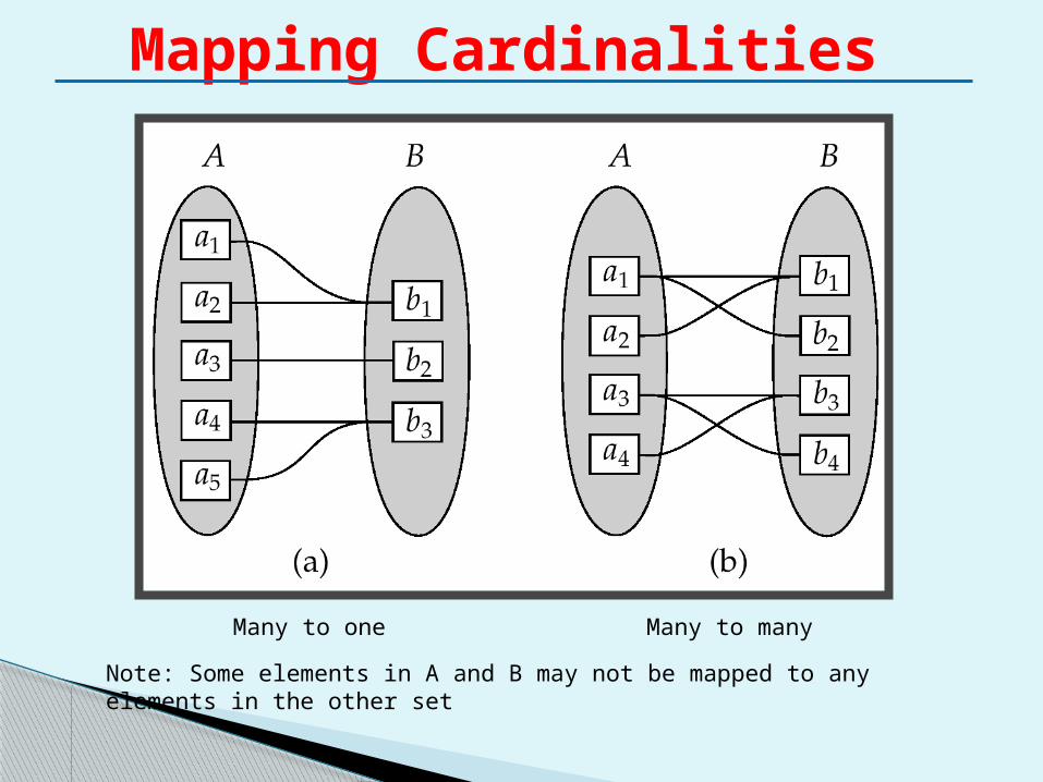
Many to one Many to many
Note: Some elements in A and B may not be mapped to any elements in the other set
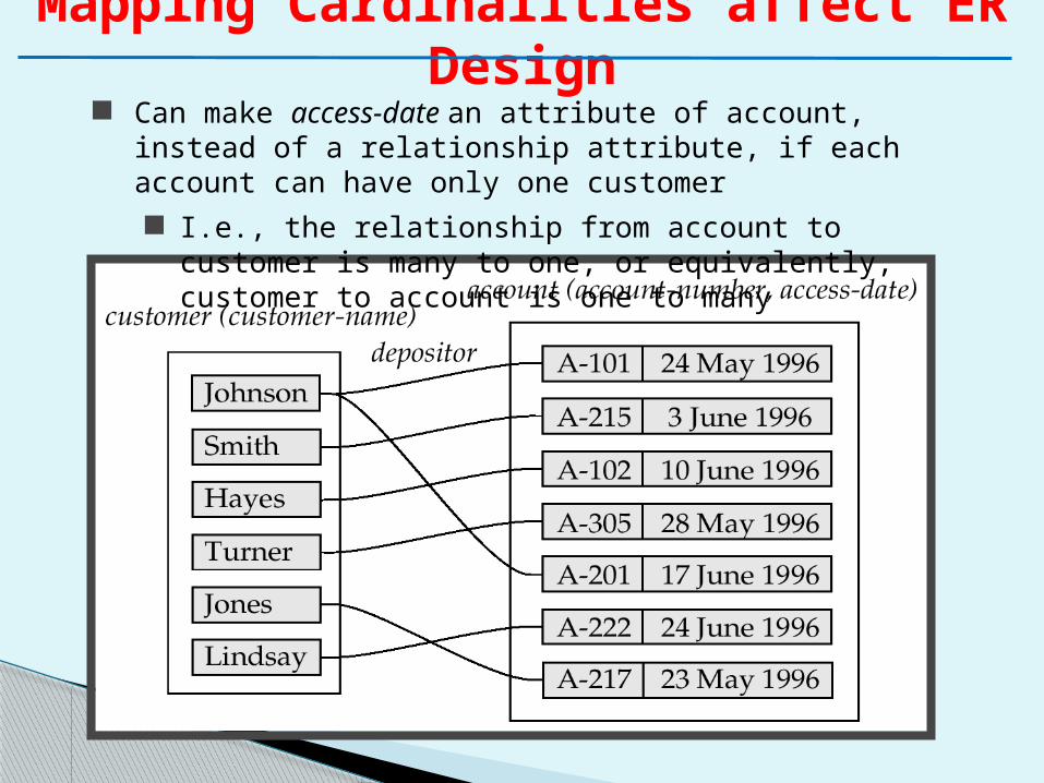
Mapping Cardinalities affect ER Design
Can make access-date an attribute of account, instead of a relationship attribute, if each account can have only one customer I.e., the relationship from account to customer is many to one,
or equivalently, customer to account is one to many
E-R Diagrams
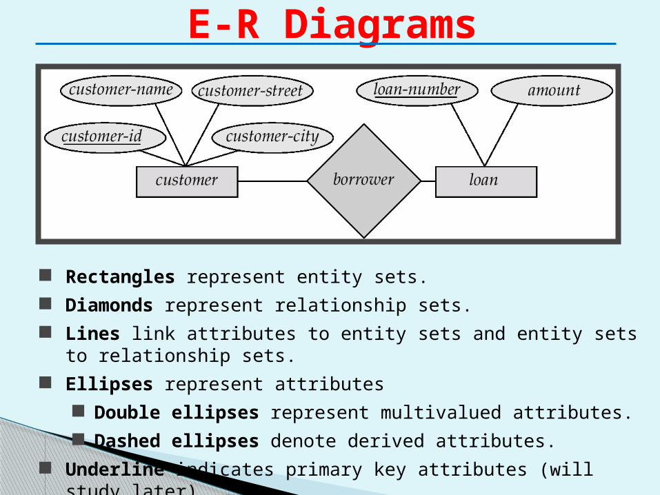
Rectangles represent entity sets. Diamonds represent relationship sets. Lines link attributes to entity sets and entity sets to relationship sets. Ellipses represent attributes
Double ellipses represent multivalued attributes. Dashed ellipses denote derived attributes.
Underline indicates primary key attributes (will study later)
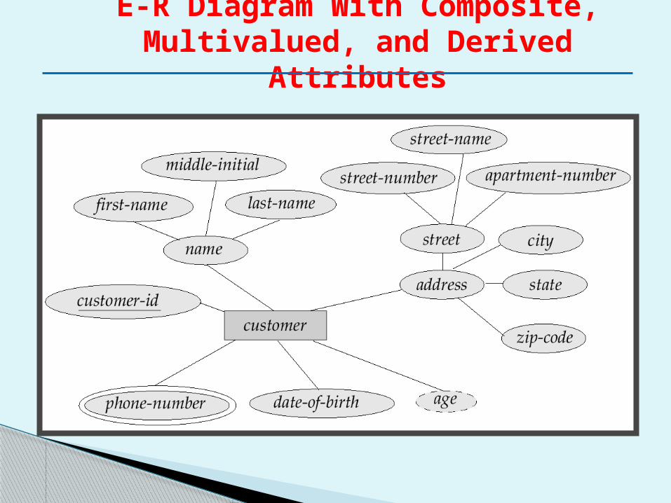
E-R Diagram With Composite, Multivalued, and Derived
Attributes
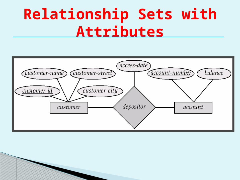
Relationship Sets with Attributes
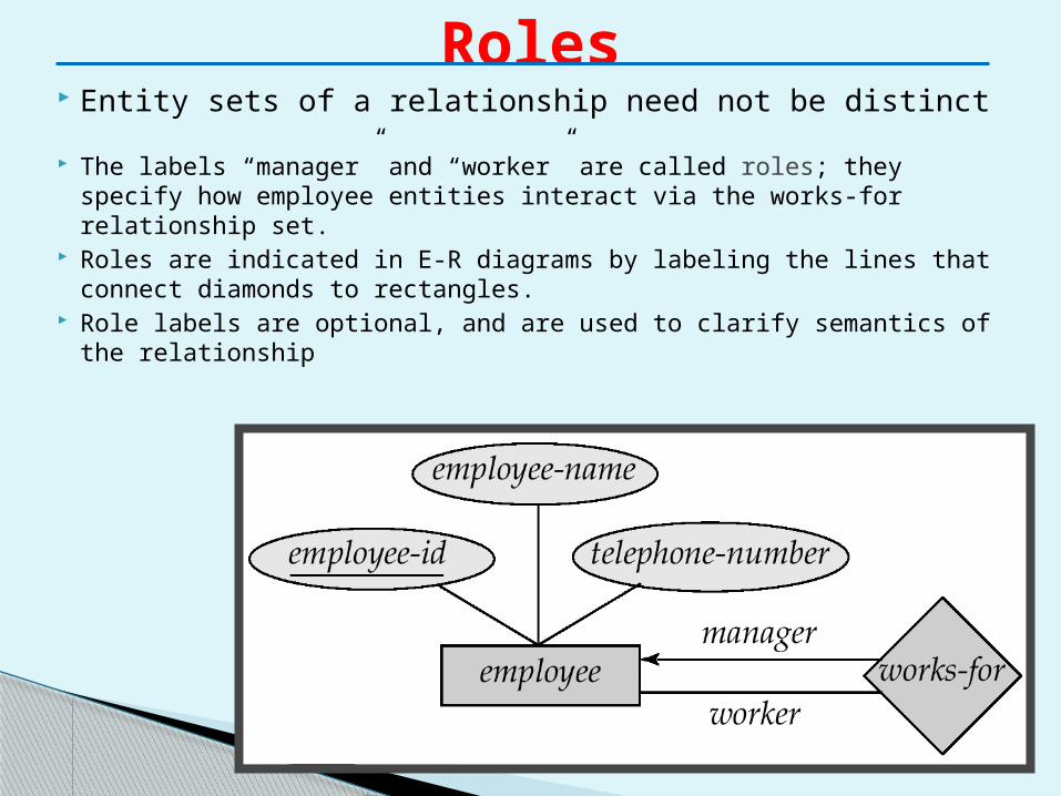
Entity sets of a relationship need not be distinct
The labels “manager” and “worker” are called roles; they specify how employee entities interact via the works-for relationship set.
Roles are indicated in E-R diagrams by labeling the lines that connect diamonds to rectangles.
Role labels are optional, and are used to clarify semantics of the relationship
Roles
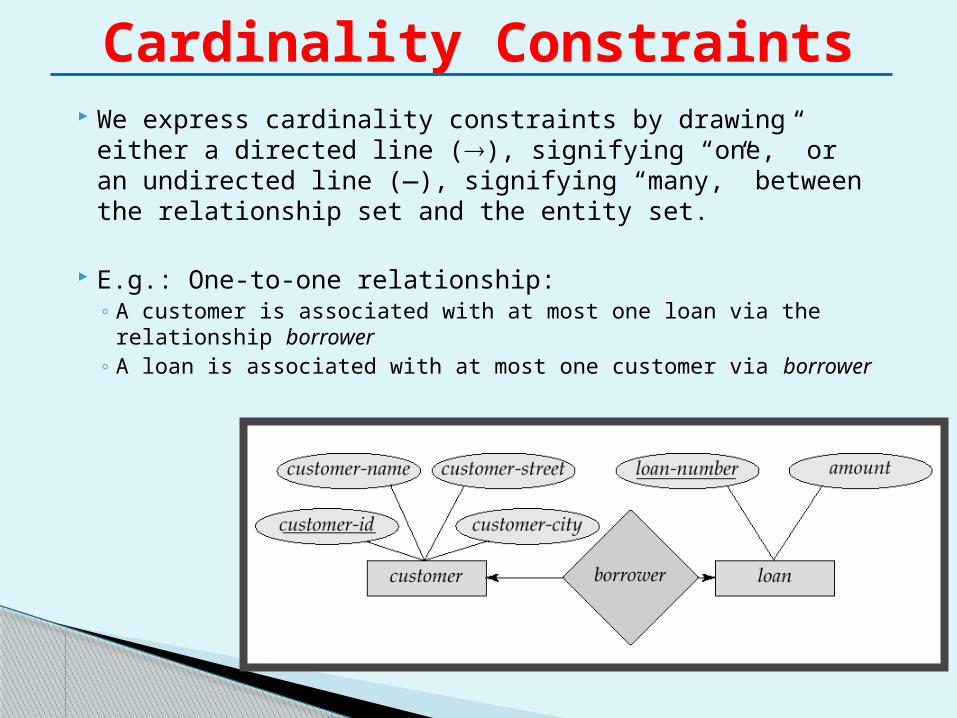
We express cardinality constraints by drawing either a directed line (), signifying “one,” or an undirected line (—), signifying “many,” between the relationship set and the entity set.
E.g.: One-to-one relationship:◦ A customer is associated with at most one loan via the
relationship borrower◦ A loan is associated with at most one customer via borrower
Cardinality Constraints
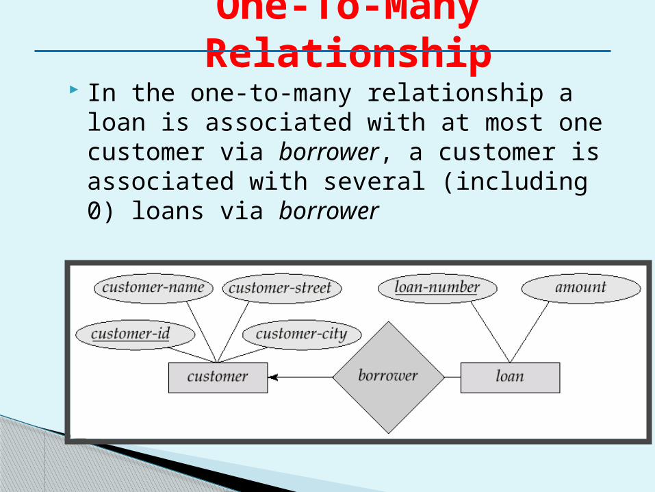
In the one-to-many relationship a loan is associated with at most one customer via borrower, a customer is associated with several (including 0) loans via borrower
One-To-Many Relationship
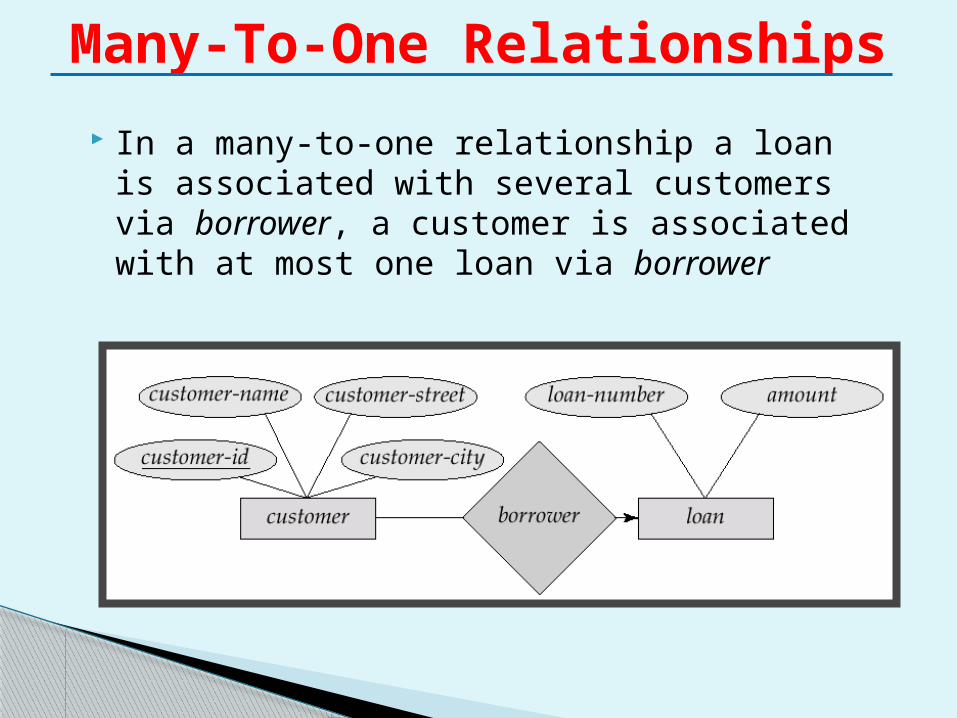
In a many-to-one relationship a loan is associated with several customers via borrower, a customer is associated with at most one loan via borrower
Many-To-One Relationships
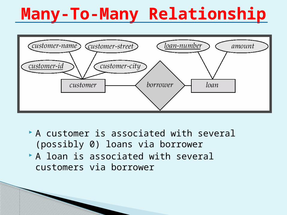
A customer is associated with several (possibly 0) loans via borrower
A loan is associated with several customers via borrower
Many-To-Many Relationship
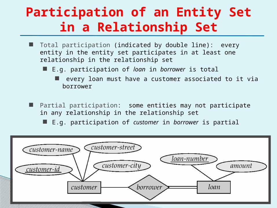
Participation of an Entity Set in a Relationship Set
Total participation (indicated by double line): every entity in the entity set participates in at least one relationship in the relationship set E.g. participation of loan in borrower is total
every loan must have a customer associated to it via borrower
Partial participation: some entities may not participate in any relationship in the relationship set E.g. participation of customer in borrower is partial
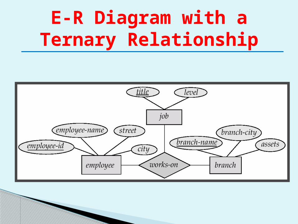
E-R Diagram with a Ternary Relationship
We allow at most one arrow out of a ternary (or greater degree) relationship to indicate a cardinality constraint
E.g. an arrow from works-on to job indicates each employee works on at most one job at any branch.
Cardinality Constraints on Ternary Relationship
An entity set that does not have a primary key is referred to as a weak entity set.
The existence of a weak entity set depends on the existence of a identifying entity set◦ it must relate to the identifying entity set via a
total, one-to-many relationship set from the identifying to the weak entity set
◦ Identifying relationship depicted using a double diamond
Weak Entity SetsWeak Entity Sets
The discriminator (or partial key) of a weak entity set is the set of attributes that distinguishes among all the entities of a weak entity set.
The primary key of a weak entity set is formed by the primary key of the strong entity set on which the weak entity set is existence dependent, plus the weak entity set’s discriminator.
Weak Entity Sets
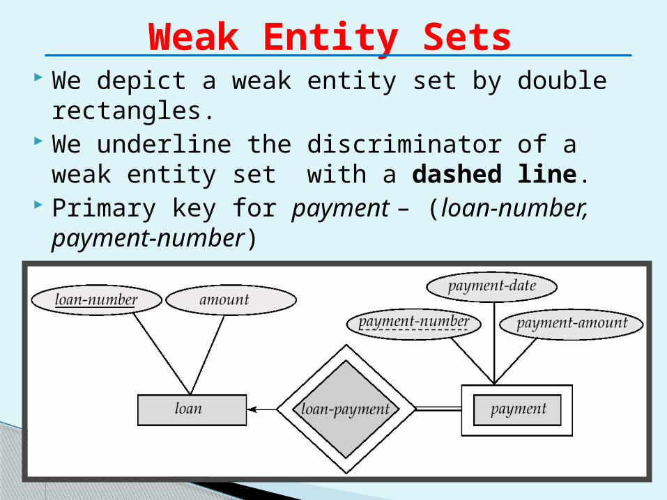
We depict a weak entity set by double rectangles.
We underline the discriminator of a weak entity set with a dashed line.
Primary key for payment – (loan-number, payment-number)
Weak Entity Sets
Note: the primary key of the strong entity set is not explicitly stored with the weak entity set, since it is implicit in the identifying relationship.
If loan-number were explicitly stored, payment could be made a strong entity, but then the relationship between payment and loan would be duplicated by an implicit relationship defined by the attribute loan-number common to payment and loan
Weak Entity Sets (Cont..)
In a university, a course is a strong entity and a course-offering can be modeled as a weak entity
The discriminator of course-offering would be semester (including year) and section-number (if there is more than one section)
If we model course-offering as a strong entity we would model course-number as an attribute. Then the relationship with course would be implicit in the course-number attribute
More Weak Entity Set Examples
Extended Entity Relationship Model
(EER Model)
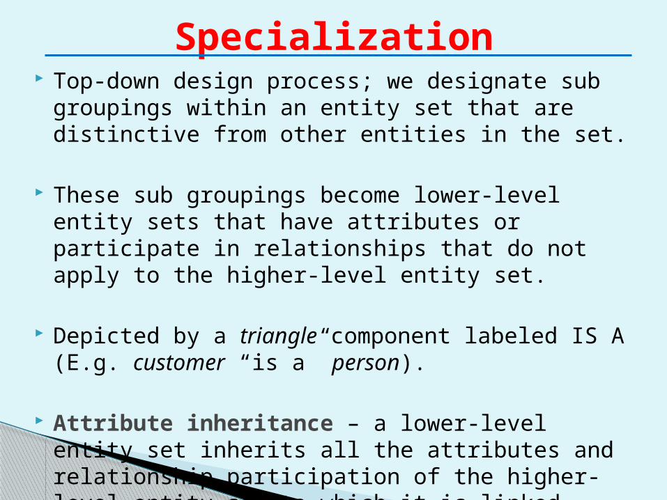
Top-down design process; we designate sub groupings within an entity set that are distinctive from other entities in the set.
These sub groupings become lower-level entity sets that have attributes or participate in relationships that do not apply to the higher-level entity set.
Depicted by a triangle component labeled IS A (E.g. customer “is a” person).
Attribute inheritance – a lower-level entity set inherits all the attributes and relationship participation of the higher-level entity set to which it is linked.
Specialization
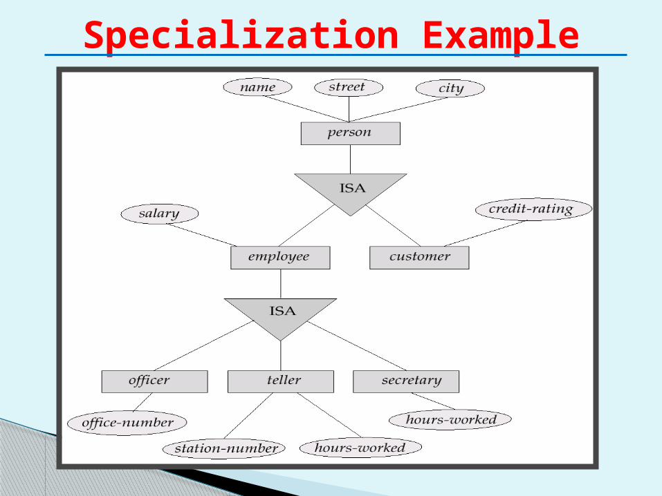
Specialization Example
A bottom-up design process – combine a number of entity sets that share the same features into a higher-level entity set.
Specialization and generalization are simple inversions of each other; they are represented in an E-R diagram in the same way.
The terms specialization and generalization are used interchangeably.
Generalization
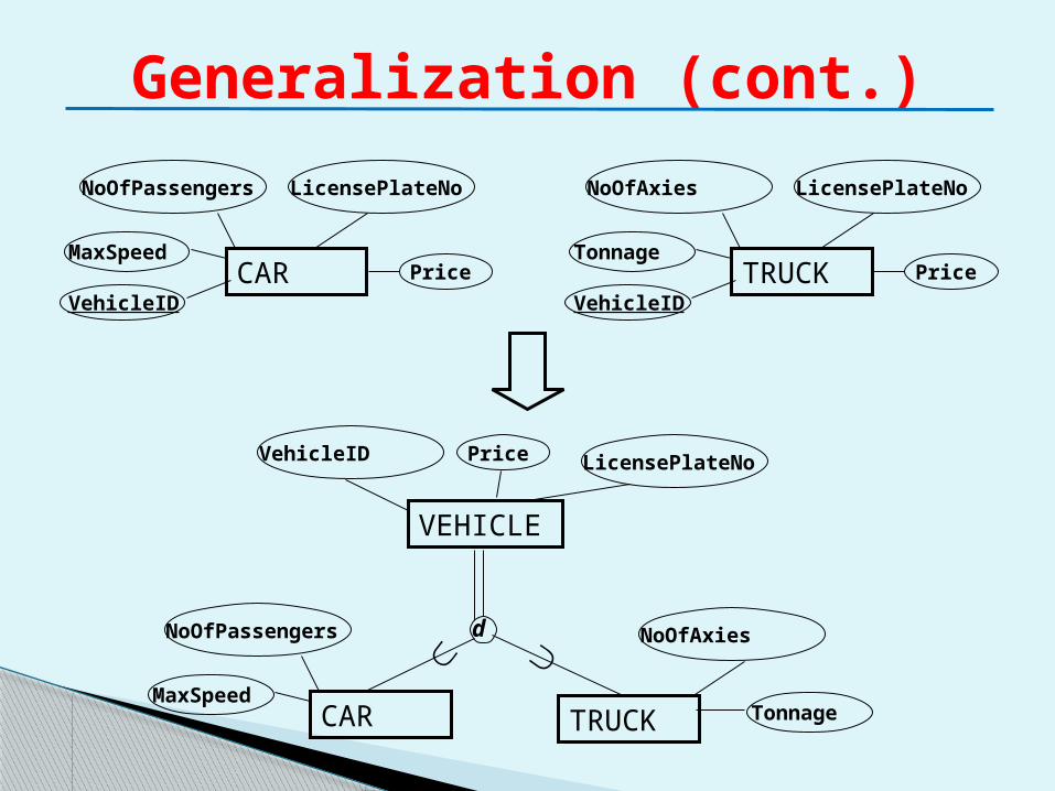
Generalization (cont.)
CAR
LicensePlateNo
PriceMaxSpeed
VehicleID
NoOfPassengers
TRUCK
LicensePlateNo
PriceTonnage
VehicleID
NoOfAxies
VEHICLE
LicensePlateNoPriceVehicleID
d
CARMaxSpeed
NoOfPassengers
TRUCK Tonnage
NoOfAxies
Generalization (Cont..)
Generalization suppresses the difference among several entity types, identifying their common features, and generalize them into a single superclass of which the original types are special subclasses.
The decision as to which process, generalization or specialization, is more appropriate in a particular situation is often subjective.
Can have multiple specializations of an entity set based on different features.
E.g. permanent-employee vs. temporary-employee, in addition to officer Vs secretary Vs teller
Each particular employee would be ◦ a member of one of permanent-employee or
temporary-employee, ◦ and also a member of one of officer, secretary, or
teller
The IS A relationship also referred to as superclass - subclass relationship
Specialization and Generalization
Constraint on which entities can be members of a given lower-level entity set.◦ condition-defined
E.g. all customers over 65 years are members of senior-citizen entity set; senior-citizen ISA person.
◦ user-defined Constraint on whether or not entities may
belong to more than one lower-level entity set within a single generalization.◦ Disjoint
an entity can belong to only one lower-level entity set Noted in E-R diagram by writing disjoint next to the
ISA triangle◦ Overlapping
an entity can belong to more than one lower-level entity set
Design Constraints on a Specialization/Generalization
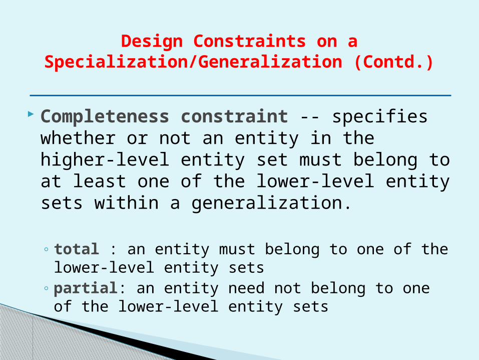
Completeness constraint -- specifies whether or not an entity in the higher-level entity set must belong to at least one of the lower-level entity sets within a generalization.
◦ total : an entity must belong to one of the lower-level entity sets
◦ partial: an entity need not belong to one of the lower-level entity sets
Design Constraints on a Specialization/Generalization (Contd.)
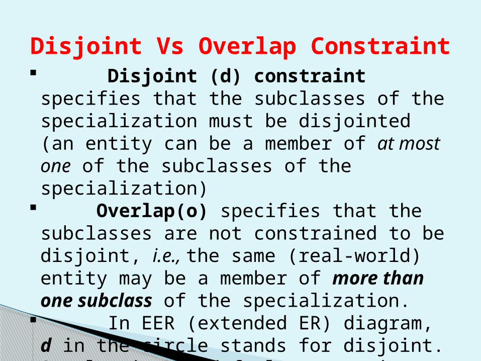
Disjoint Vs Overlap Constraint Disjoint (d) constraint specifies that the
subclasses of the specialization must be disjointed (an entity can be a member of at most one of the subclasses of the specialization)
Overlap(o) specifies that the subclasses are not constrained to be disjoint, i.e., the same (real-world) entity may be a member of more than one subclass of the specialization.
In EER (extended ER) diagram, d in the circle stands for disjoint. Overlap is the default constraint and displayed by placing an o in the circle.
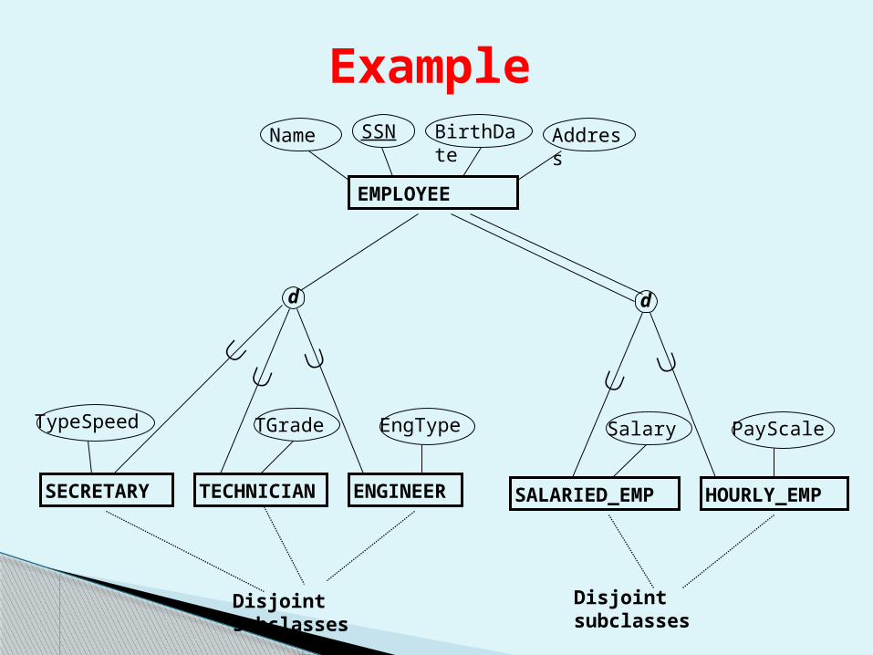
Example
EMPLOYEE
Name SSN BirthDate Address
SECRETARY
d
TypeSpeed
TECHNICIAN
TGrade
ENGINEER
EngType
d
SALARIED_EMP
Salary
HOURLY_EMP
PayScale
Disjoint subclasses Disjoint subclasses
Completeness constraint Completeness constraint may be total or partial. A total specialization constraint specifies that every
entity in the superclass must be a member of some subclass in the specialization.
A partial specialization allows an entity not to belong to any of the subclasses, using a single line in EER.
e.g., if some EMPLOYEE entities, for example, sales representatives, do not belong to any of the subclasses {SECRETARY, ENGINEER, TECHNICIAN}, then the specialization is partial.
Total is represented by a double line connecting the
superclass to the circle. Partial is represented by a single line connecting the superclass to the circle.
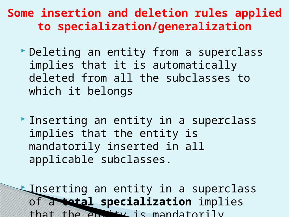
Some insertion and deletion rules applied to specialization/generalization
Deleting an entity from a superclass implies that it is automatically deleted from all the subclasses to which it belongs
Inserting an entity in a superclass implies that the entity is mandatorily inserted in all applicable subclasses.
Inserting an entity in a superclass of a total specialization implies that the entity is mandatorily inserted in at least one of the subclasses of the specialization.
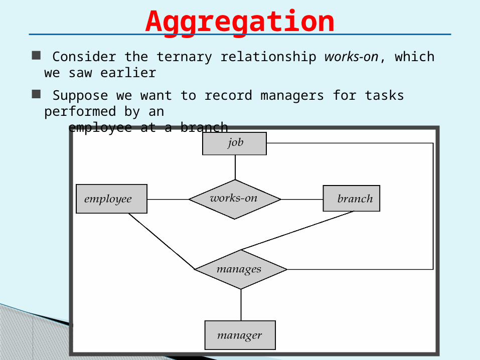
Aggregation Consider the ternary relationship works-on, which we saw earlier
Suppose we want to record managers for tasks performed by an employee at a branch
Relationship sets works-on and manages represent overlapping information◦ Every manages relationship corresponds to a works-
on relationship◦ However, some works-on relationships may not
correspond to any manages relationships So we can’t discard the works-on relationship
Eliminate this redundancy via aggregation◦ Treat relationship as an abstract entity◦ Allows relationships between relationships ◦ Abstraction of relationship into new entity
Aggregation (Cont.)
Without introducing redundancy, the following diagram represents:
◦ An employee works on a particular job at a particular branch
◦ An employee, branch, job combination may have an associated manager
Aggregation (Cont.)
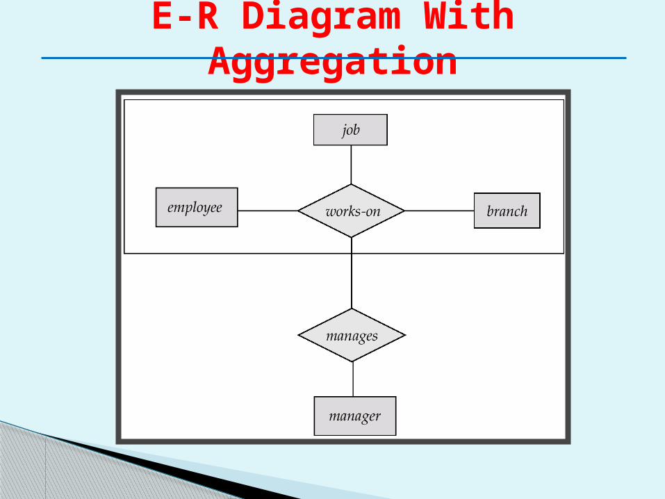
E-R Diagram With Aggregation
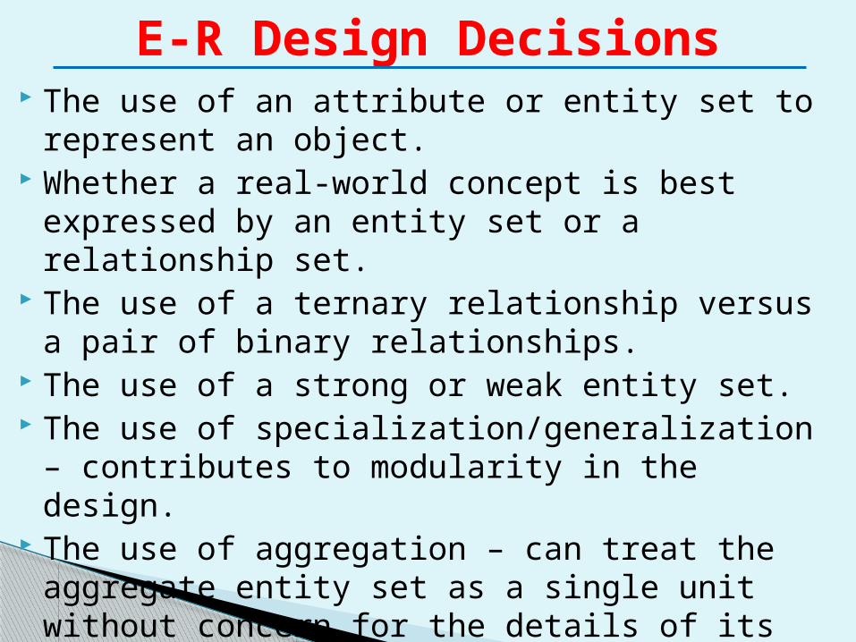
The use of an attribute or entity set to represent an object.
Whether a real-world concept is best expressed by an entity set or a relationship set.
The use of a ternary relationship versus a pair of binary relationships.
The use of a strong or weak entity set. The use of specialization/generalization –
contributes to modularity in the design. The use of aggregation – can treat the aggregate
entity set as a single unit without concern for the details of its internal structure.
E-R Design Decisions
Now Lets make an ER diagram for Banking
Enterprise
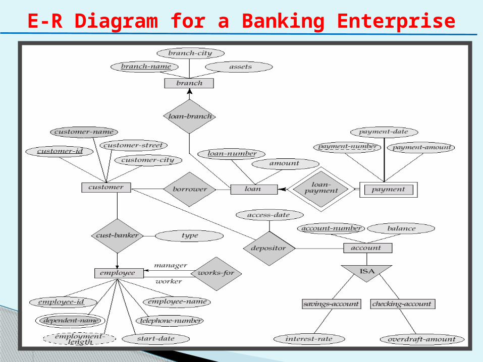
E-R Diagram for a Banking Enterprise
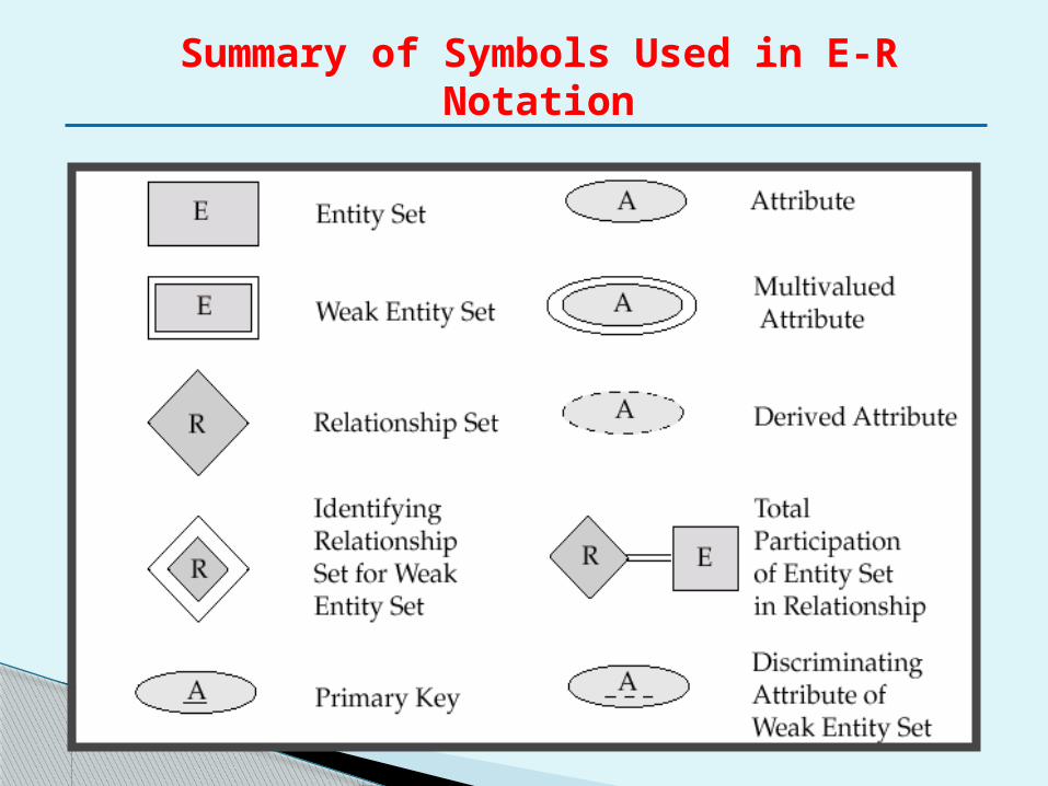
Summary of Symbols Used in E-R Notation
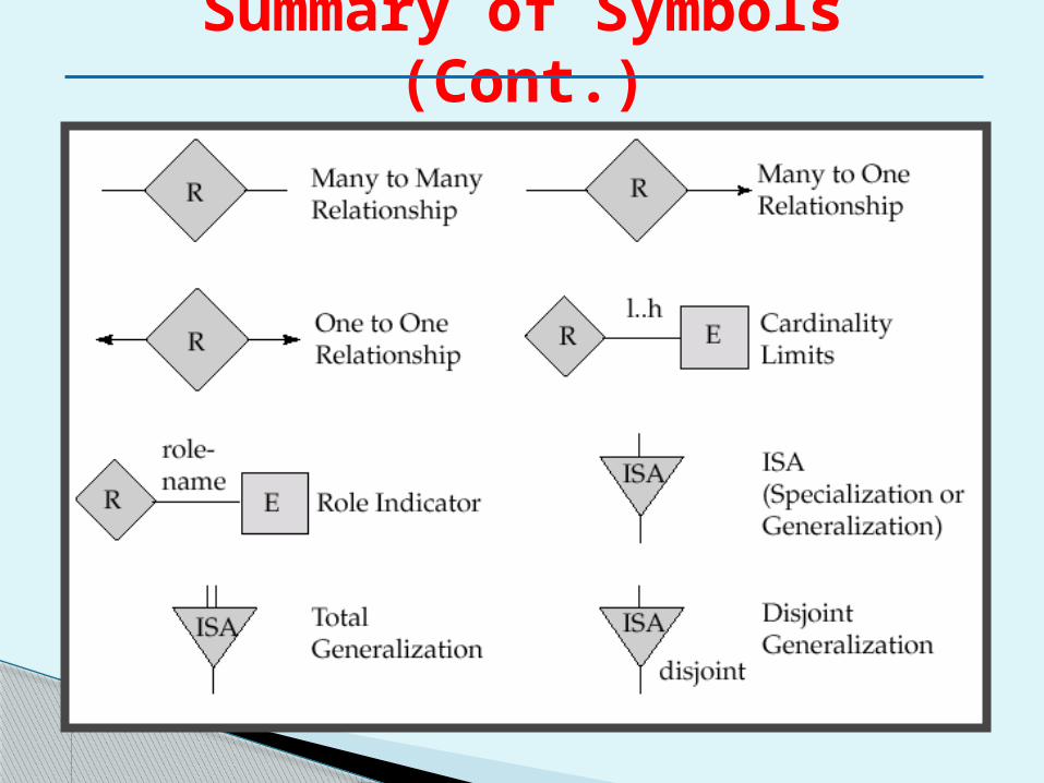
Summary of Symbols (Cont.)
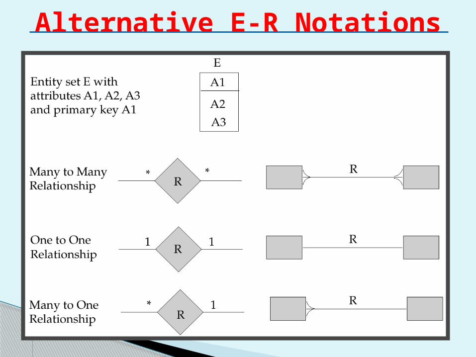
Alternative E-R Notations


![Index [editorial.mcpressonline.com]editorial.mcpressonline.com/web/mcpdf.nsf/wdocs/... · Database Administrator (DBA), 1 Database Administrator (DBADM), 50 database managed space](https://img.pdfslide.us/doc/110x75/5f04e6ca7e708231d410466c/index-database-administrator-dba-1-database-administrator-dbadm-50-database.jpg)