Embed Size (px)
Citation preview

© Prentice Hall© Prentice Hall 11
Chapter 1:Chapter 1:
The Database The Database EnvironmentEnvironment

22Chapter 1 & 2 © Prentice Hall© Prentice Hall
ObjectivesObjectives Definition of termsDefinition of terms Explain growth and importance of databasesExplain growth and importance of databases Name limitations of conventional file Name limitations of conventional file
processingprocessing Identify five categories of databasesIdentify five categories of databases Explain advantages of databasesExplain advantages of databases Identify costs and risks of databasesIdentify costs and risks of databases List components of database environmentList components of database environment Describe evolution of database systemsDescribe evolution of database systems
33Chapter 1 & 2 © Prentice Hall© Prentice Hall
DefinitionsDefinitions Data: stored representations of meaningful Data: stored representations of meaningful
objects and eventsobjects and events Structured: numbers, text, datesStructured: numbers, text, dates Unstructured: images, video, documentsUnstructured: images, video, documents
Database: organized collection of logically Database: organized collection of logically related datarelated data
Information: data processed to increase Information: data processed to increase knowledge in the person using the dataknowledge in the person using the data
Metadata: data that describes the properties Metadata: data that describes the properties and context of user dataand context of user data

44Chapter 1 & 2 © Prentice Hall© Prentice Hall
Systems and Systems and ProceduresProcedures
Product flow and information flowProduct flow and information flow Product flow: the flow of raw materials into Product flow: the flow of raw materials into
assemblies and finally into finished goods.assemblies and finally into finished goods. Information flow: the creation of movement Information flow: the creation of movement
of the administrative and operational of the administrative and operational documentation necessary for product flow.documentation necessary for product flow.

55Chapter 1 & 2 © Prentice Hall© Prentice Hall
Product flow and Information Product flow and Information flowflow
Customers Employees
Collection (8)
Sales(5)
Production(4)
Distribution(6)
Inventory(3)
Receiving(2)
Paying(9)
Purchasing(1)
VendorsBilling
(7)
Data to Information flow is as if raw material to production flow.

66Chapter 1 & 2 © Prentice Hall© Prentice Hall
The evolution of product flow The evolution of product flow and information flowand information flow
data processing information
raw materials
productionfinishedgoods
Input Output
furtherprocessing
??
technicalsupport
??
77Chapter 1 & 2 © Prentice Hall© Prentice Hall
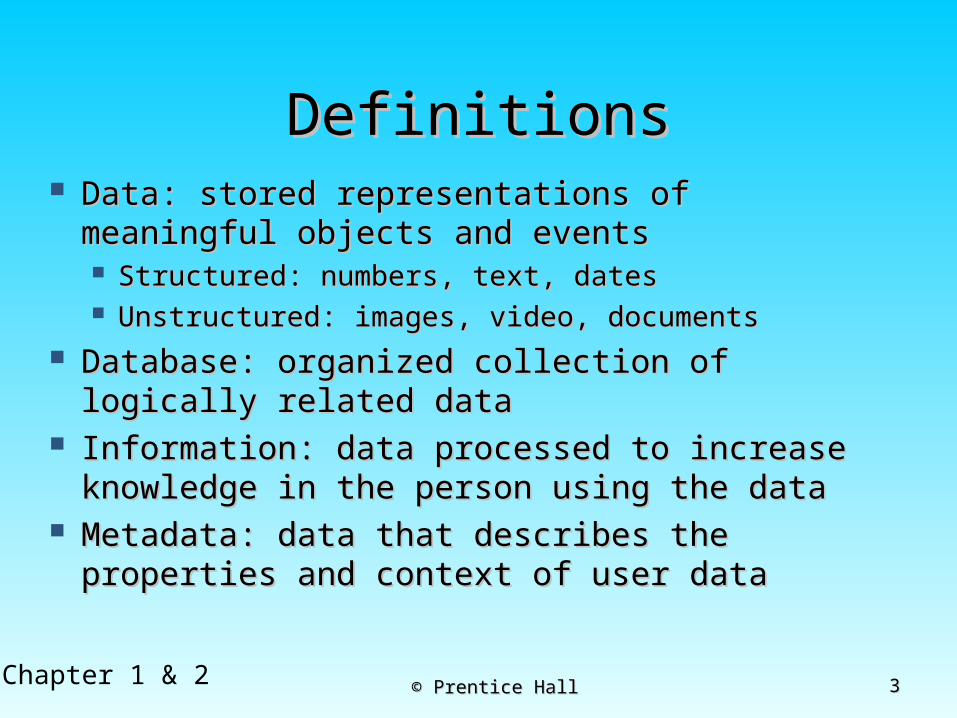
Figure 1-1a Data in context
Context helps users understand data
88Chapter 1 & 2 © Prentice Hall© Prentice Hall
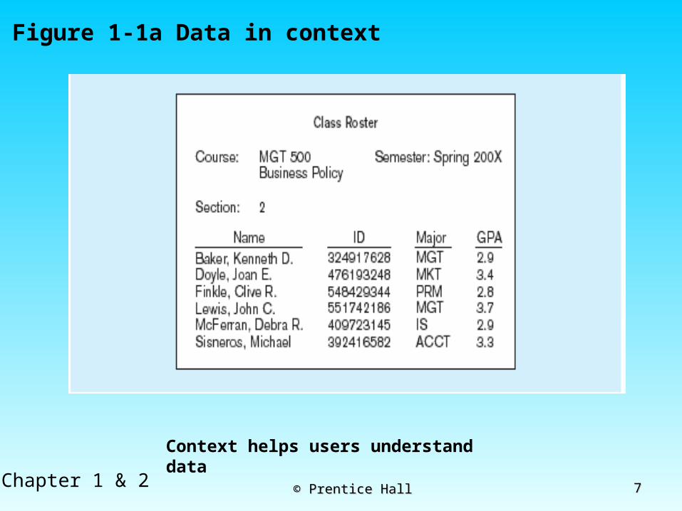
Graphical displays turn data into useful information that managers can use for decision making and
interpretation
Figure 1-1b Summarized data

99Chapter 1 & 2 © Prentice Hall© Prentice Hall
Descriptions of the properties or characteristics of the data, including data types, field sizes, allowable values, and
data context

1010Chapter 1 & 2 © Prentice Hall© Prentice Hall
Disadvantages of File Disadvantages of File ProcessingProcessing
Program-Data DependenceProgram-Data Dependence All programs maintain metadata for each file they useAll programs maintain metadata for each file they use
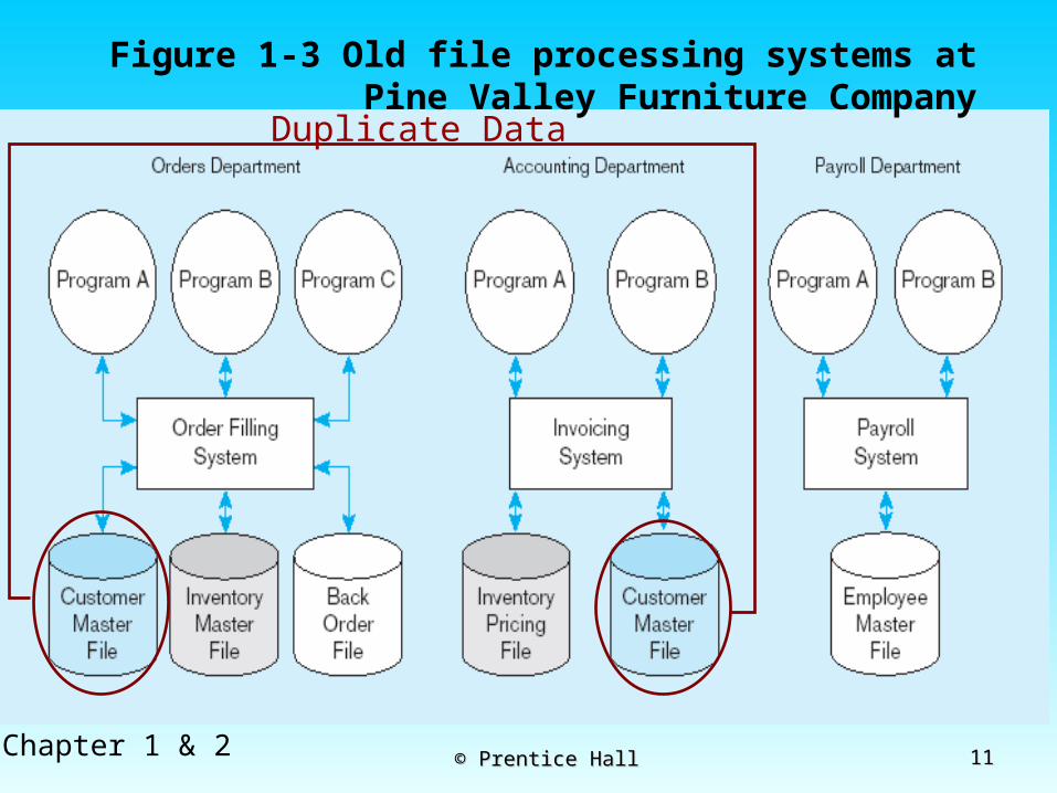
Duplication of DataDuplication of Data Different systems/programs have separate copies of the Different systems/programs have separate copies of the
same datasame data
Limited Data SharingLimited Data Sharing No centralized control of dataNo centralized control of data
Lengthy Development TimesLengthy Development Times Programmers must design their own file formatsProgrammers must design their own file formats
Excessive Program MaintenanceExcessive Program Maintenance 80% of information systems budget80% of information systems budget
1111Chapter 1 & 2 © Prentice Hall© Prentice Hall
Figure 1-3 Old file processing systems at Pine Valley Furniture Company
Duplicate Data

1212Chapter 1 & 2 © Prentice Hall© Prentice Hall
Problems with Program Data Problems with Program Data DependencyDependency
Each application programmer must Each application programmer must maintain his/her own datamaintain his/her own data
Each application program needs to Each application program needs to include code for the metadata of each include code for the metadata of each filefile
Each application program must have its Each application program must have its own processing routines for own processing routines for database database operationsoperations: reading, inserting, updating, : reading, inserting, updating, and deleting dataand deleting data
Lack of coordination and central controlLack of coordination and central control Non-standard file formatsNon-standard file formats
1313Chapter 1 & 2 © Prentice Hall© Prentice Hall
Problems with Data Problems with Data RedundancyRedundancy
Waste of space to have duplicate dataWaste of space to have duplicate data Causes more maintenance headachesCauses more maintenance headaches The biggest problem: The biggest problem:
Data changes in one file could cause Data changes in one file could cause inconsistenciesinconsistencies
Compromises in Compromises in data integritydata integrity

1414Chapter 1 & 2 © Prentice Hall© Prentice Hall
SOLUTION: SOLUTION: The DATABASE ApproachThe DATABASE Approach
Central repository of shared dataCentral repository of shared data Data is managed by a controlling Data is managed by a controlling
agentagent Stored in a standardized, Stored in a standardized,
convenient formconvenient form
Requires a Database Management System (DBMS)
1515Chapter 1 & 2 © Prentice Hall© Prentice Hall
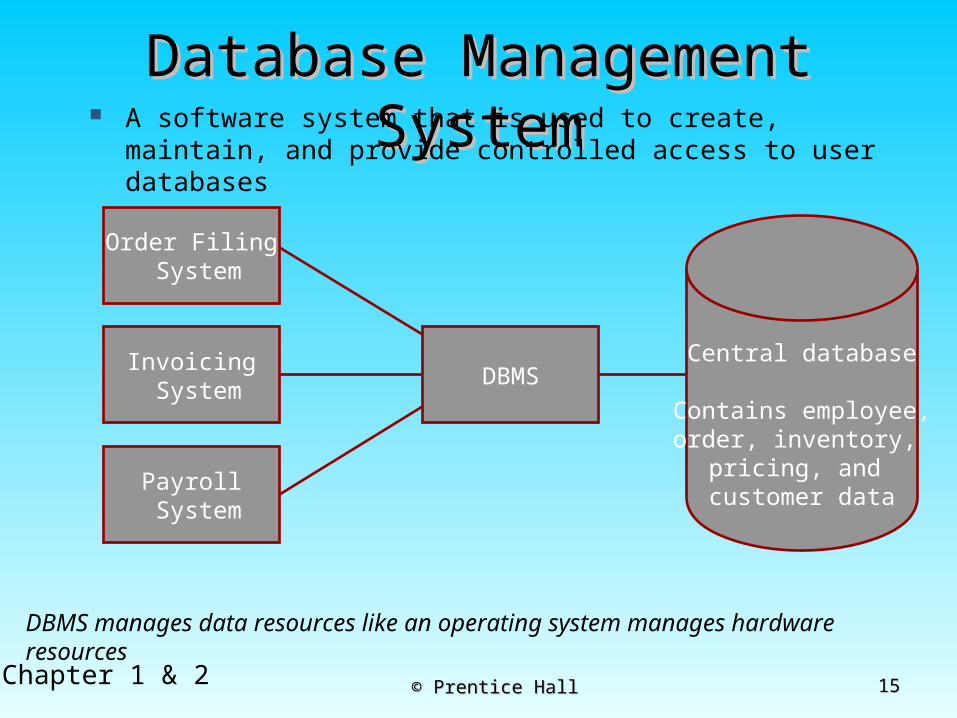
Database Management Database Management SystemSystem
DBMS manages data resources like an operating system manages hardware resources
A software system that is used to create, maintain, and provide controlled access to user databases
Order Filing System
Invoicing System
Payroll System
DBMSCentral database
Contains employee,order, inventory,
pricing, and customer data
1616Chapter 1 & 2 © Prentice Hall© Prentice Hall
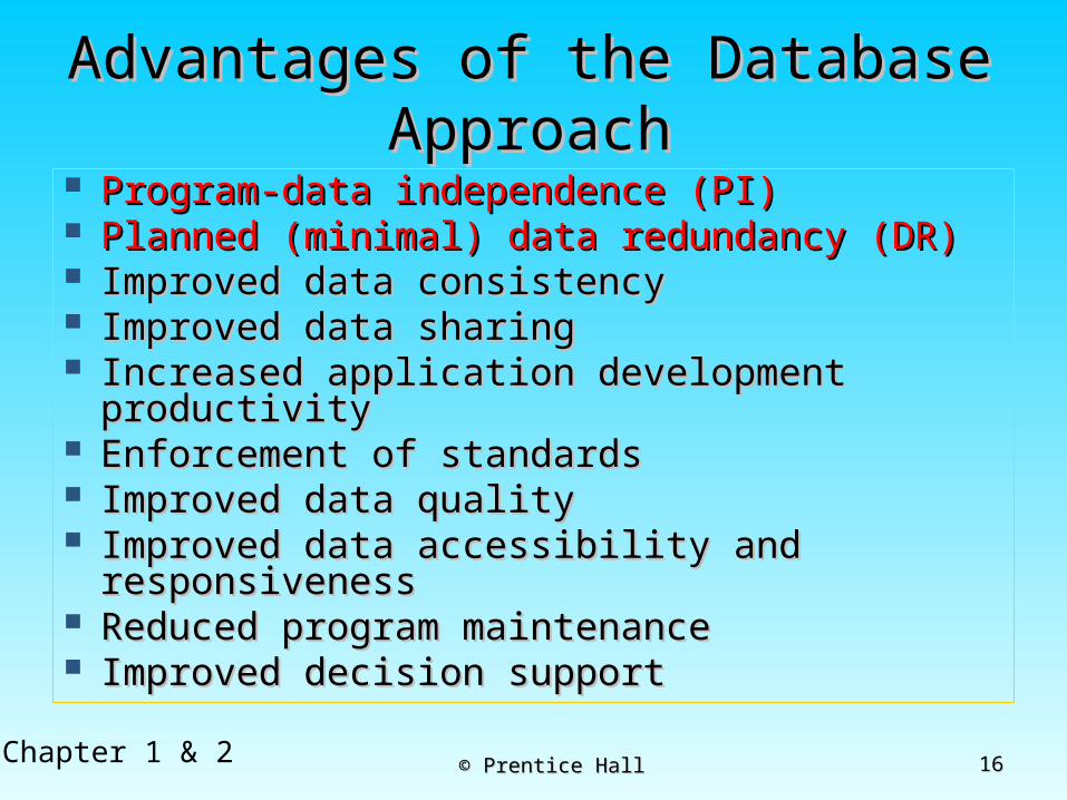
Advantages of the Database Advantages of the Database ApproachApproach
Program-data independence (PI)Program-data independence (PI) Planned (minimal) data redundancy (DR)Planned (minimal) data redundancy (DR) Improved data consistencyImproved data consistency Improved data sharingImproved data sharing Increased application development Increased application development
productivityproductivity Enforcement of standardsEnforcement of standards Improved data qualityImproved data quality Improved data accessibility and Improved data accessibility and
responsivenessresponsiveness Reduced program maintenanceReduced program maintenance Improved decision supportImproved decision support
1717Chapter 1 & 2 © Prentice Hall© Prentice Hall
Costs and Risks of the Database Costs and Risks of the Database ApproachApproach
New, specialized personnelNew, specialized personnel Installation and management cost Installation and management cost
and complexityand complexity Conversion costsConversion costs Need for explicit backup and Need for explicit backup and
recoveryrecovery Organizational conflictOrganizational conflict

1818Chapter 1 & 2 © Prentice Hall© Prentice Hall
Figure 2-9 Three-tiered client/server database architecture
Data tier
Presentation tier
Business logic tier

1919Chapter 1 & 2 © Prentice Hall© Prentice Hall
Evolution of DB SystemsEvolution of DB Systems
© Prentice Hall© Prentice Hall 2020
Chapter 2:Chapter 2:
The Database The Database Development Process Development Process
2121Chapter 1 & 2 © Prentice Hall© Prentice Hall
ObjectivesObjectives Definition of termsDefinition of terms Describe system development life cycleDescribe system development life cycle Explain prototyping approachExplain prototyping approach Explain roles of individualsExplain roles of individuals Explain three-schema approachExplain three-schema approach Explain role of packaged data modelsExplain role of packaged data models Explain three-tiered architecturesExplain three-tiered architectures Explain scope of database design projectsExplain scope of database design projects Draw simple data modelsDraw simple data models
2222Chapter 1 & 2 © Prentice Hall© Prentice Hall
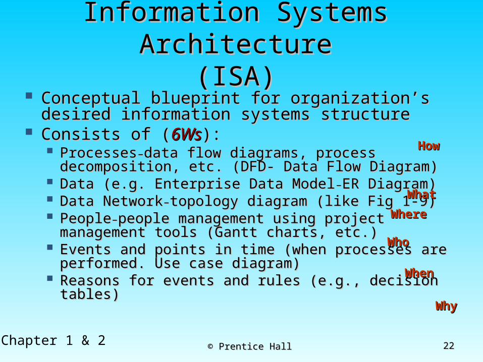
Information Systems Information Systems ArchitectureArchitecture
(ISA)(ISA) Conceptual blueprint for organization’s Conceptual blueprint for organization’s
desired information systems structuredesired information systems structure Consists of (Consists of (6Ws6Ws):):
ProcessesProcesses––data flow diagrams, process data flow diagrams, process decomposition, etc. (DFD- Data Flow Diagram)decomposition, etc. (DFD- Data Flow Diagram)
Data (e.g. Enterprise Data ModelData (e.g. Enterprise Data Model––ER Diagram)ER Diagram) Data NetworkData Network––topology diagram (like Fig 1-9)topology diagram (like Fig 1-9) PeoplePeople––people management using project people management using project
management tools (Gantt charts, etc.)management tools (Gantt charts, etc.) Events and points in time (when processes are Events and points in time (when processes are
performed. Use case diagram)performed. Use case diagram) Reasons for events and rules (e.g., decision Reasons for events and rules (e.g., decision
tables)tables)
WhatWhat
HowHow
WhereWhere
WhoWho
WhenWhen
WhyWhy

2323Chapter 1 & 2 © Prentice Hall© Prentice Hall
Data Flow DiagramsData Flow Diagrams Data flow diagrams (DFDs) are Data flow diagrams (DFDs) are
graphical aids that describe an graphical aids that describe an information systeminformation system
Advantages:Advantages: freedom from committing to the technical freedom from committing to the technical
implementation of the system too early.implementation of the system too early. Further understanding the Further understanding the
interrelatedness of systems and interrelatedness of systems and subsystems.subsystems.
communicating current system communicating current system knowledge to users .knowledge to users .

2424Chapter 1 & 2 © Prentice Hall© Prentice Hall
Data Flow DiagramsData Flow Diagrams
Data flow diagram symbolsData flow diagram symbols Four basic symbolsFour basic symbols
ProcessProcess
Data flowData flow
Data storeData store
External entityExternal entity

2525Chapter 1 & 2 © Prentice Hall© Prentice Hall
Process
Data flowsExternal entities
2626Chapter 1 & 2 © Prentice Hall© Prentice Hall
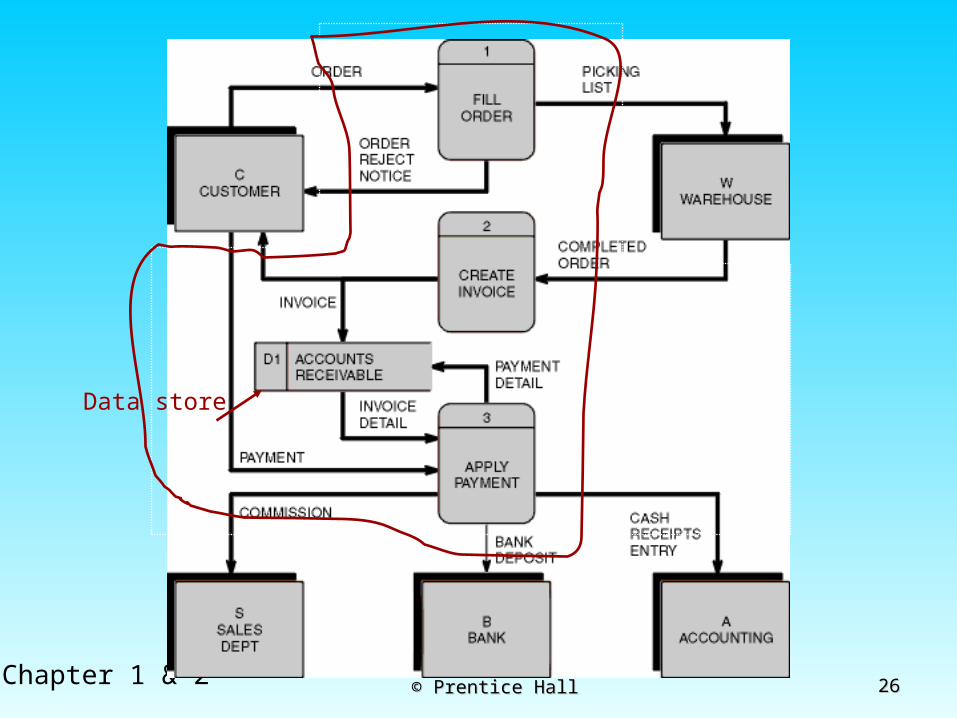
Data store
2727Chapter 1 & 2 © Prentice Hall© Prentice Hall

2828Chapter 1 & 2 © Prentice Hall© Prentice Hall

2929Chapter 1 & 2 © Prentice Hall© Prentice Hall
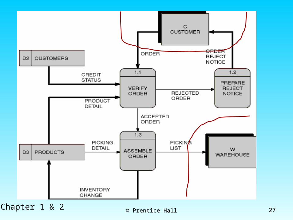
Figure 2-2 Example of process decomposition of an order fulfillment function (Pine Valley Furniture)
Decomposition = breaking large tasks into smaller tasks in a hierarchical structure chart
Order form Credit status

3030Chapter 1 & 2 © Prentice Hall© Prentice Hall
Information Systems Information Systems ArchitectureArchitecture
(ISA)(ISA) Conceptual blueprint for organization’s Conceptual blueprint for organization’s
desired information systems structuredesired information systems structure Consists of (Consists of (6Ws6Ws):):
ProcessesProcesses––data flow diagrams, process data flow diagrams, process decomposition, etc. (DFD- Data Flow Diagram)decomposition, etc. (DFD- Data Flow Diagram)
Data (e.g. Enterprise Data ModelData (e.g. Enterprise Data Model––ER Diagram)ER Diagram) Data NetworkData Network––topology diagram (like Fig 1-9)topology diagram (like Fig 1-9) PeoplePeople––people management using project people management using project
management tools (Gantt charts, etc.)management tools (Gantt charts, etc.) Events and points in time (when processes are Events and points in time (when processes are
performed. Use case diagram)performed. Use case diagram) Reasons for events and rules (e.g., decision Reasons for events and rules (e.g., decision
tables)tables)
WhatWhat
HowHow
WhereWhere
WhoWho
WhenWhen
WhyWhy
3131Chapter 1 & 2 © Prentice Hall© Prentice Hall
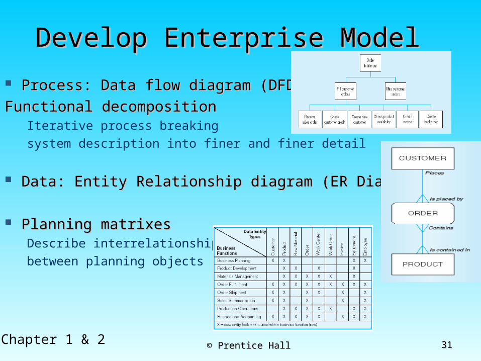
Develop Enterprise ModelDevelop Enterprise Model
Process: Data flow diagram (DFD)Process: Data flow diagram (DFD)
Functional decompositionFunctional decompositionIterative process breaking system description into finer and finer detail
Data: Entity Relationship diagram (ER Diagram)Data: Entity Relationship diagram (ER Diagram)
Planning matrixes Planning matrixes Describe interrelationships between planning objects
3232Chapter 1 & 2 © Prentice Hall© Prentice Hall
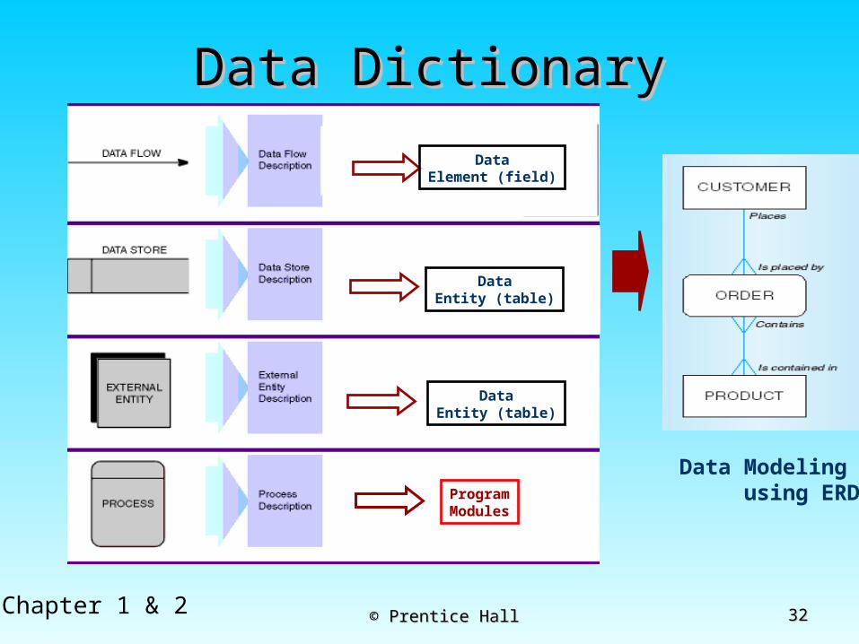
Data DictionaryData Dictionary
DataEntity (table)
ProgramModules
DataEntity (table)
DataElement (field)
Data Modeling using ERD

3333Chapter 1 & 2 © Prentice Hall© Prentice Hall
Example business function-Example business function-to-data entity matrix (Fig. 2-to-data entity matrix (Fig. 2-
3)3)Higherpriority
Spot missing entity

3434Chapter 1 & 2 © Prentice Hall© Prentice Hall
Planning MatrixesPlanning Matrixes Describe relationships between Describe relationships between
planning objects in the organizationplanning objects in the organization Types of matrixes:Types of matrixes:
Function-to-data entityFunction-to-data entity Location-to-functionLocation-to-function Unit-to-functionUnit-to-function IS-to-data entityIS-to-data entity Supporting function-to-data entitySupporting function-to-data entity IS-to-business objectiveIS-to-business objective
3535Chapter 1 & 2 © Prentice Hall© Prentice Hall
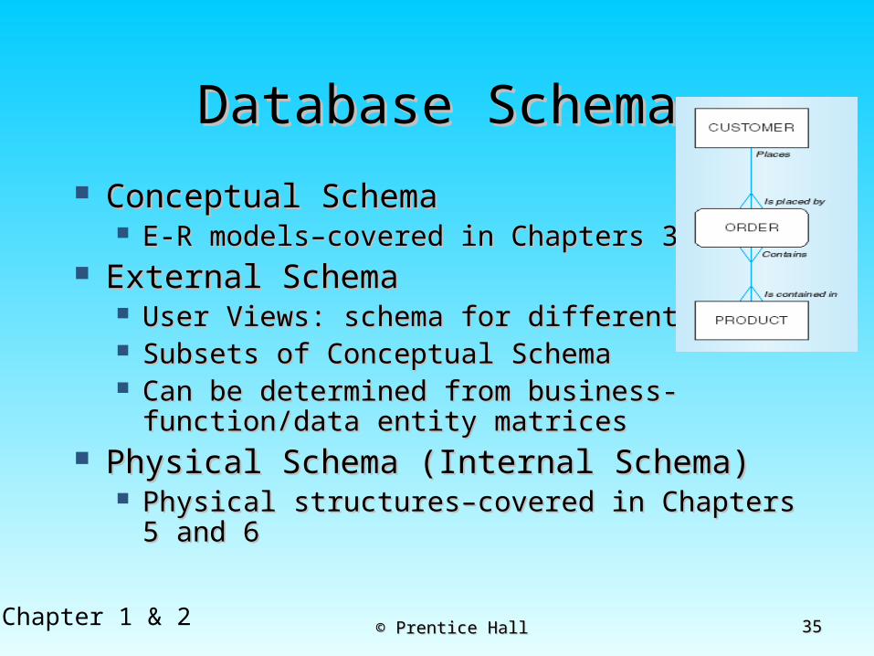
Database SchemaDatabase Schema Conceptual SchemaConceptual Schema
E-R models–covered in Chapters 3 and 4E-R models–covered in Chapters 3 and 4 External SchemaExternal Schema
User Views: schema for different usersUser Views: schema for different users Subsets of Conceptual SchemaSubsets of Conceptual Schema Can be determined from Can be determined from
business-function/data entity matricesbusiness-function/data entity matrices Physical Schema (Internal Schema)Physical Schema (Internal Schema)
Physical structures–covered in Chapters 5 Physical structures–covered in Chapters 5 and 6and 6

3636Chapter 1 & 2 © Prentice Hall© Prentice Hall
Different people have different views of the database…these are the external schema
The internal schema is the underlying design and implementation
Figure 2-7 Three-schema architecture

3737Chapter 1 & 2 © Prentice Hall© Prentice Hall
Figure 2-8 Developing the three-tiered architecture
3838Chapter 1 & 2 © Prentice Hall© Prentice Hall
Information EngineeringInformation Engineering Top-down planning–a generic IS Top-down planning–a generic IS
planning methodology for obtaining a planning methodology for obtaining a broad understanding of the IS needed broad understanding of the IS needed by the entire organizationby the entire organization
Four steps to Top-Down planning:Four steps to Top-Down planning: PlanningPlanning AnalysisAnalysis DesignDesign ImplementationImplementation

3939Chapter 1 & 2 © Prentice Hall© Prentice Hall
Two Approaches to Two Approaches to Database and IS Database and IS
DevelopmentDevelopment SDLCSDLC System Development Life CycleSystem Development Life Cycle Detailed, well-planned development processDetailed, well-planned development process Time-consuming, but comprehensiveTime-consuming, but comprehensive Long development cycleLong development cycle
PrototypingPrototyping Rapid application development (RAD)Rapid application development (RAD) Cursory attempt at conceptual data modelingCursory attempt at conceptual data modeling Define database during development of initial prototypeDefine database during development of initial prototype Repeat implementation and maintenance activities with Repeat implementation and maintenance activities with
new prototype versionsnew prototype versions

4040Chapter 1 & 2 © Prentice Hall© Prentice Hall
Systems Development Life CycleSystems Development Life Cycle(see also Figures 2.4, 2.5) (see also Figures 2.4, 2.5)
Planning
Analysis
Physical Design
Implementation
Maintenance
Logical Design
4141Chapter 1 & 2 © Prentice Hall© Prentice Hall
Systems planning Purpose – identify problem’s nature/scope Systems request – begins the process &
describes desired changes/improvements Systems planning – includes preliminary
investigation or feasibility study End product – preliminary investigation report
Systems Development Life Cycle
4242Chapter 1 & 2 © Prentice Hall© Prentice Hall
Systems analysis Purpose is to learn exactly how the current
system operates or determine what systems should do.
Fact-finding or requirements determination is used to define all functions of the current system
Systems Development Life Cycle

4343Chapter 1 & 2 © Prentice Hall© Prentice Hall
Options Develop a system in-house Purchase a commercial package Modify an existing system Stop development
The end product for this phase is the systems requirements document
Systems Development Life Cycle

4444Chapter 1 & 2 © Prentice Hall© Prentice Hall
Systems design Purpose is to satisfy all documented requirements identify what and how the system must do. Identify all outputs, inputs, files, manual procedures, &
application programs user interface design, files organization and database
design Avoid misunderstanding through manager and user
involvement End product is system design specification
Systems Development Life Cycle
4545Chapter 1 & 2 © Prentice Hall© Prentice Hall
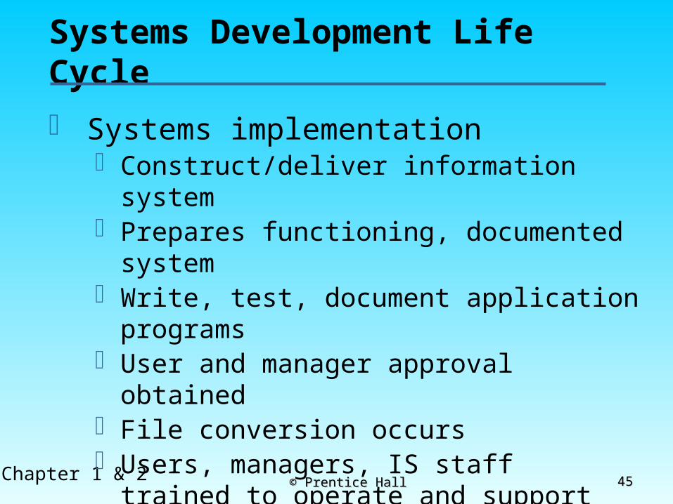
Systems implementationConstruct/deliver information system Prepares functioning, documented systemWrite, test, document application programsUser and manager approval obtainedFile conversion occursUsers, managers, IS staff trained to operate and
support the systemPost-implementation evaluation performed
Systems Development Life Cycle

4646Chapter 1 & 2 © Prentice Hall© Prentice Hall
Prototyping Database Prototyping Database MethodologyMethodology(Figure 2.6) (Figure 2.6)
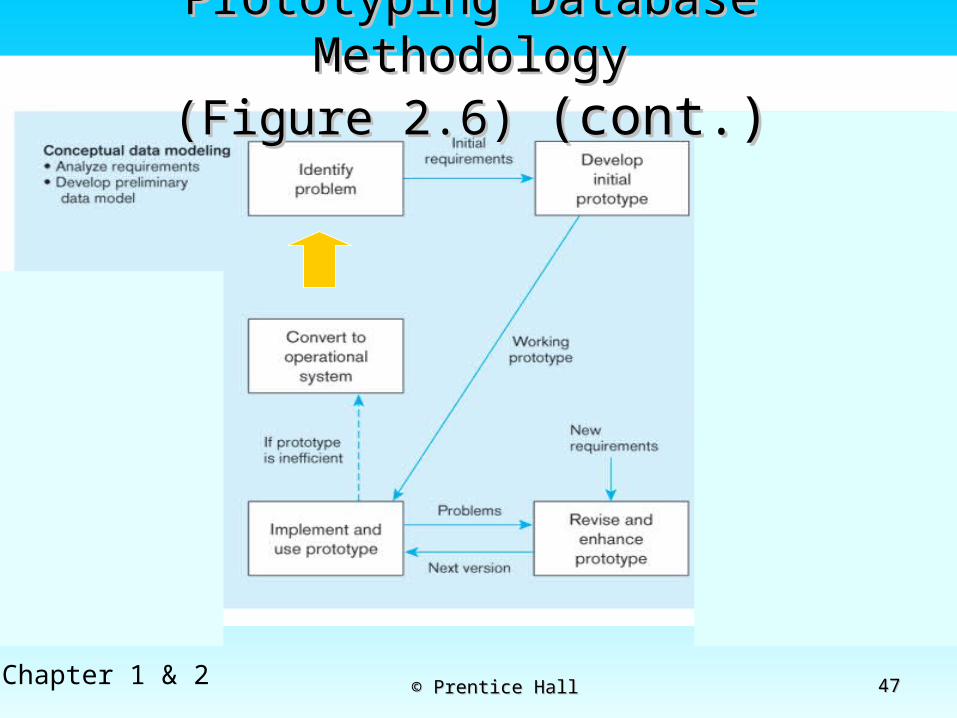
4747Chapter 1 & 2 © Prentice Hall© Prentice Hall
Prototyping Database Prototyping Database MethodologyMethodology
(Figure 2.6) (Figure 2.6) (cont.)(cont.)

4848Chapter 1 & 2 © Prentice Hall© Prentice Hall
Prototyping Database Prototyping Database MethodologyMethodology
(Figure 2.6)(Figure 2.6) (cont.) (cont.)
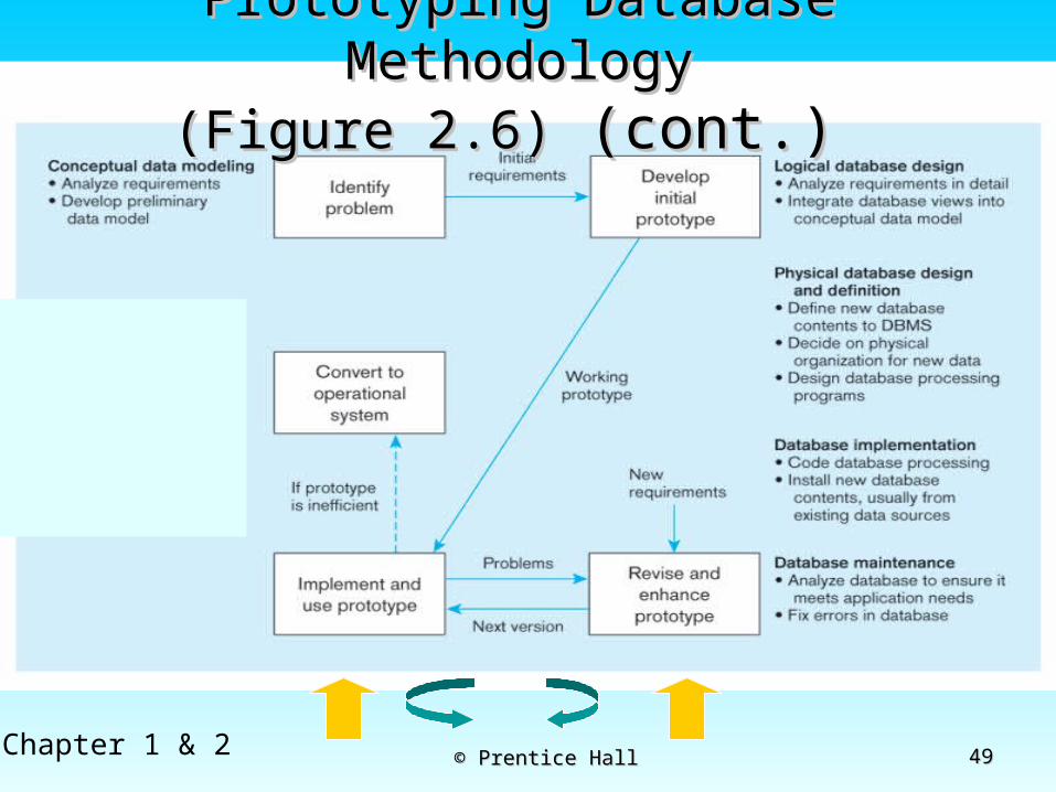
4949Chapter 1 & 2 © Prentice Hall© Prentice Hall
Prototyping Database Prototyping Database MethodologyMethodology
(Figure 2.6)(Figure 2.6) (cont.) (cont.)
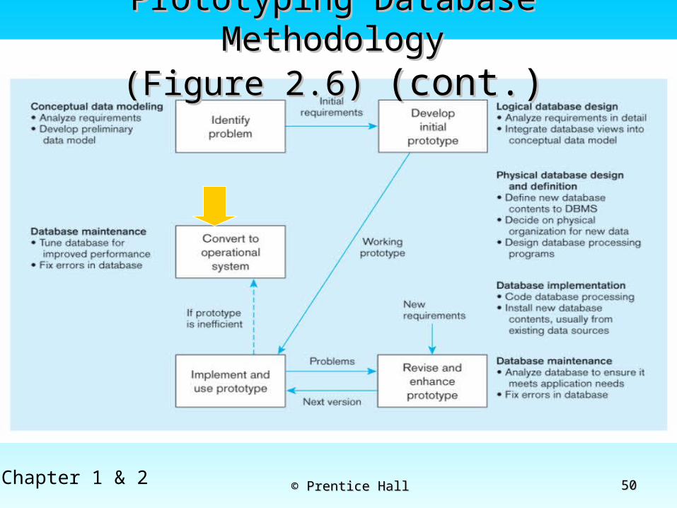
5050Chapter 1 & 2 © Prentice Hall© Prentice Hall
Prototyping Database Prototyping Database MethodologyMethodology
(Figure 2.6) (Figure 2.6) (cont.)(cont.)
5151Chapter 1 & 2 © Prentice Hall© Prentice Hall
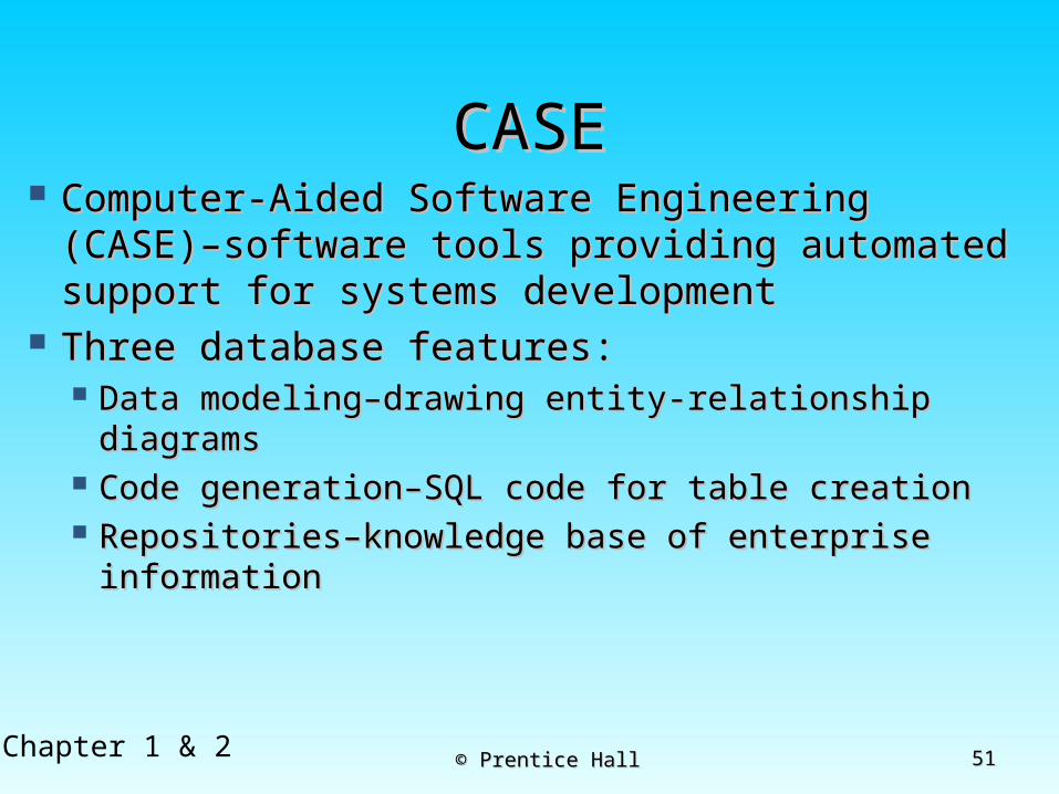
CASECASE Computer-Aided Software Engineering Computer-Aided Software Engineering
(CASE)–software tools providing automated (CASE)–software tools providing automated support for systems developmentsupport for systems development
Three database features:Three database features: Data modeling–drawing entity-relationship Data modeling–drawing entity-relationship
diagramsdiagrams Code generation–SQL code for table creationCode generation–SQL code for table creation Repositories–knowledge base of enterprise Repositories–knowledge base of enterprise
informationinformation

5252Chapter 1 & 2 © Prentice Hall© Prentice Hall
Managing Projects: People Managing Projects: People InvolvedInvolved
Business analystsBusiness analysts Systems analystsSystems analysts Database analysts and data modelersDatabase analysts and data modelers UsersUsers ProgrammersProgrammers Database architectsDatabase architects Data administratorsData administrators Project managersProject managers Other technical expertsOther technical experts
5353Chapter 1 & 2 © Prentice Hall© Prentice Hall
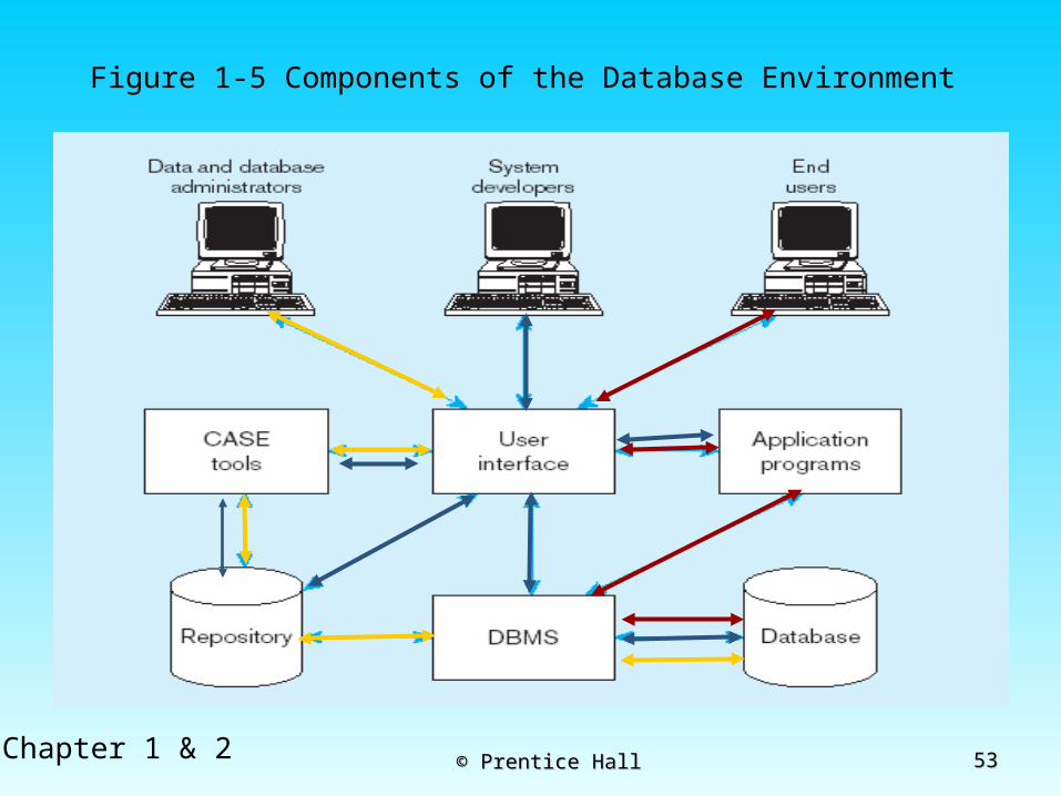
Figure 1-5 Components of the Database Environment