Embed Size (px)
Citation preview
CD 7012, ISSUE 2, 08/03/2015 1
Ericsson AIR 21/AIR 32 Mounting Instructions
** Please use and understand all required safety procedures for
working near and around RF radiating equipment and its various
mounting locations. **
This document is informational and advisory in nature and does not
constitute a complete guide to operating Sunsight Instruments
Products. Use the information at your own risk.
For questions or additional information, please contact:
Sunsight Instruments
125 Candace Drive
Maitland FL 32751
USA
321.244.9443
Note that this document may change from time to time
CD 7012, ISSUE 2, 08/03/2015 2
Ericsson AIR 21/AIR 32 Mounting Instructions
Instructions for using the AntennAlign Alignment Tool (AAT)
Ericsson AIR 21/AIR 32 Mount
Introduction:
To address the ever changing variety of antennas in the cellular industry, Sunsight Instruments
periodically introduces new mounting systems for its various measuring and aligning products. This
instruction manual will discuss the Ericsson AIR 21 and the AIR 21/Air 32 Antenna Mounts and their
proper use with the AntennAlign Alignment Tool (AAT).
** NOTE 1: The Ericsson ERICSSON AIR 21 or AIR 21/AIR 32 Mount MUST be used with the AAT to get
accurate results when aligning the AIR 21. The AIR 21/AIR 32 mount MUST be used in the AIR 32
configuration when aligning AIR 32 antennas. Standard AAT mounts will give inaccurate results due to
the complex shape of the AIR antennas.
**NOTE 2: Customers that already own an AIR 21 Classic antenna mount may return the mount to
Sunsight Instruments for modification to convert it to an AIR 21/AIR 32 mount for use on both AIR 21
and AIR 32 antennas.
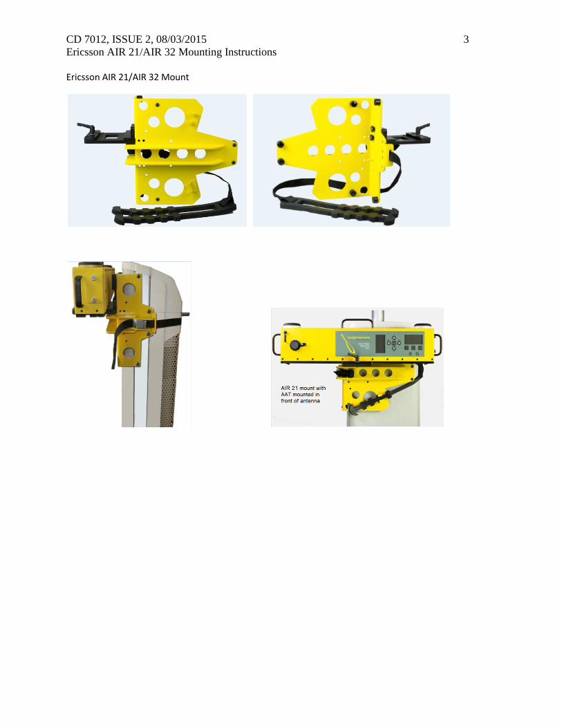
**NOTE 3: If you are previously familiar with the AIR 21 mount for the classic AAT, you will find only
one difference between the AIR 21 mount and the AIR21/AIR32 mount. The AIR 21/AIR 32 mount has
two movable threaded bumpers and knobs. The bumpers/knobs have holes that correspond to
drilled holes in the mount that are labeled as “21” or “32”. If you are going to align an AIR 21
antenna, secure the two bumpers and knobs in the two holes marked “21”. For AIR 32 alignments,
secure the bumpers in the two holes marked “32” instead.
***
FAILURE TO USE THE CORRECT HOLES FOR THE THREADED BUMPERS/KNOBS
WILL RESULT IN INCORRECT ALIGNMENT OF THE AIR ANTENNA.
***
CD 7012, ISSUE 2, 08/03/2015 3
Ericsson AIR 21/AIR 32 Mounting Instructions
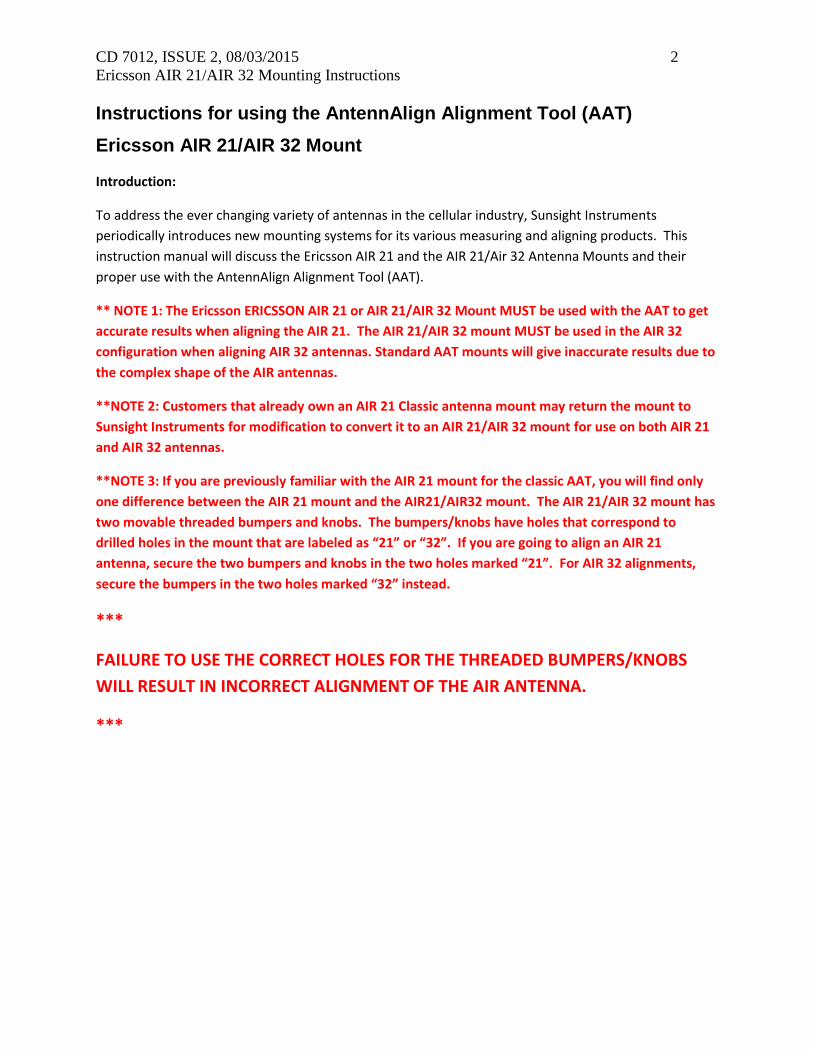
Ericsson AIR 21/AIR 32 Mount
CD 7012, ISSUE 2, 08/03/2015 4
Ericsson AIR 21/AIR 32 Mounting Instructions
CD 7012, ISSUE 2, 08/03/2015 5
Ericsson AIR 21/AIR 32 Mounting Instructions
PREPARING THE MOUNT FOR USE
** If the AIR 21/AIR 32 Mount is new, adjust the grip plate to the AAT with which it will be used.
Refer to the section on adjusting the grip plate near the end of this document if required.
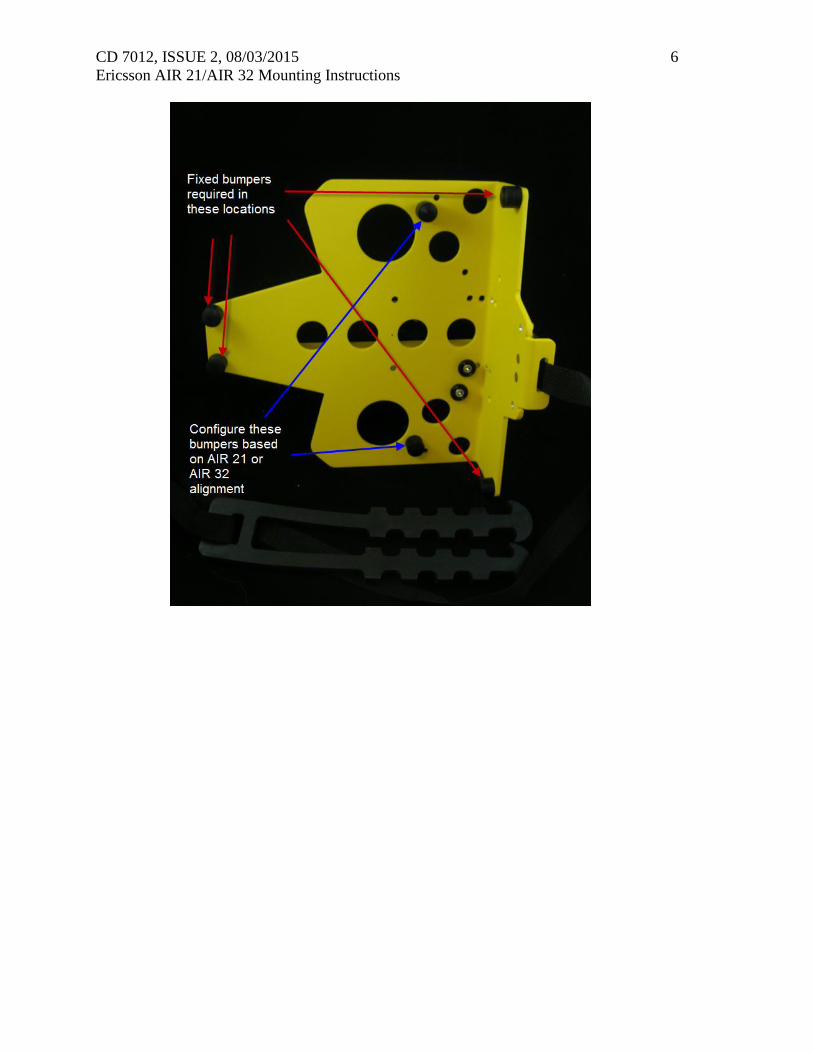
1) Be sure that the mounting strap is installed in the mount and that the required bumpers are
in place and in good serviceable condition.
2) If you are using the AIR 21 mount (not the AIR 21/AIR 32 mount), there are no movable
threaded bumper/knobs. All bumper are in a fixed position, so skip to step 3. Otherwise,
continue with the following instruction.
** NOTE: The type and position of the rubber bumpers is fixed EXCEPT FOR THE TWO
THREADED BUMPERS/KNOBS. Do not use the mount without the fixed bumpers as well as
the two threaded bumpers/knobs. Moving, removing, or using the AIR 21/AIR 32Mount
with bumpers incorrectly installed, missing or damaged will result in inaccurate
measurements. **
CD 7012, ISSUE 2, 08/03/2015 6
Ericsson AIR 21/AIR 32 Mounting Instructions
CD 7012, ISSUE 2, 08/03/2015 7
Ericsson AIR 21/AIR 32 Mounting Instructions
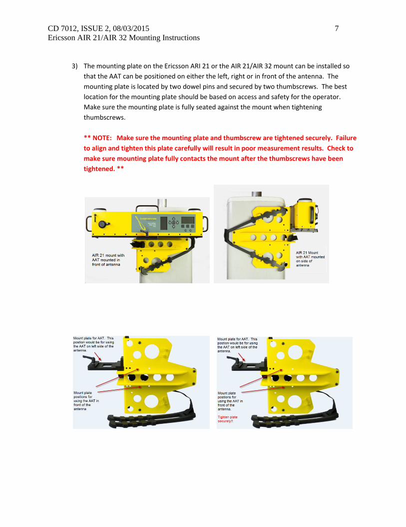
3) The mounting plate on the Ericsson ARI 21 or the AIR 21/AIR 32 mount can be installed so
that the AAT can be positioned on either the left, right or in front of the antenna. The
mounting plate is located by two dowel pins and secured by two thumbscrews. The best
location for the mounting plate should be based on access and safety for the operator.
Make sure the mounting plate is fully seated against the mount when tightening
thumbscrews.
** NOTE: Make sure the mounting plate and thumbscrew are tightened securely. Failure
to align and tighten this plate carefully will result in poor measurement results. Check to
make sure mounting plate fully contacts the mount after the thumbscrews have been
tightened. **
CD 7012, ISSUE 2, 08/03/2015 8
Ericsson AIR 21/AIR 32 Mounting Instructions
Mounting and Measuring using the Ericsson AIR 21 or AIR 21/AIR 32Mount
The AIR 21 and the AIR 21/AIR 32 antenna mount is unlike the standard AAT side mount in that
the main plate of the mount goes IN FRONT of the antenna rather than behind it. This location
allows the precisely spaced bumpers to match the highly contoured shape of the AIR 21/AIR 32
antenna in a reliable and repeatable way.
** Always use a safety tether on any items when working on a tower. This includes the AIR
21, or the AIR 21/AIR 32 Mount and AAT. **
** Do not attempt to mount either AIR mount to the antenna with the AAT installed. The AAT
will be installed later. **
1) Determine the type of antenna to be aligned (AIR 21 or AIR 32). Install the two threaded
bumpers/knobs in the holes corresponding to the type of antenna *** only the AIR 21/AIR 32
mount has the configurable bumpers ***.
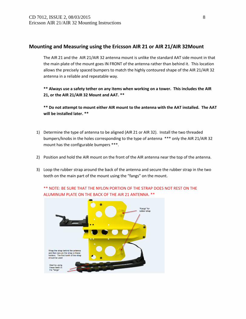
2) Position and hold the AIR mount on the front of the AIR antenna near the top of the antenna.
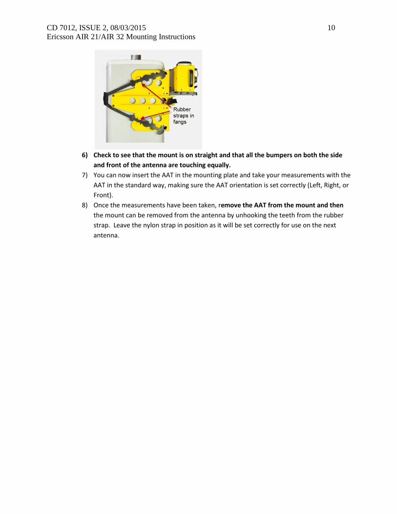
3) Loop the rubber strap around the back of the antenna and secure the rubber strap in the two
teeth on the main part of the mount using the “fangs” on the mount.
** NOTE: BE SURE THAT THE NYLON PORTION OF THE STRAP DOES NOT REST ON THE
ALUMINUM PLATE ON THE BACK OF THE AIR 21 ANTENNA. **
CD 7012, ISSUE 2, 08/03/2015 9
Ericsson AIR 21/AIR 32 Mounting Instructions
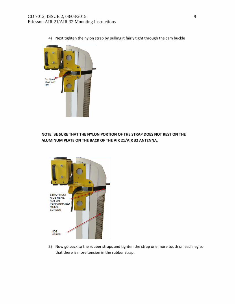
4) Next tighten the nylon strap by pulling it fairly tight through the cam buckle
NOTE: BE SURE THAT THE NYLON PORTION OF THE STRAP DOES NOT REST ON THE
ALUMINUM PLATE ON THE BACK OF THE AIR 21/AIR 32 ANTENNA.
5) Now go back to the rubber straps and tighten the strap one more tooth on each leg so
that there is more tension in the rubber strap.
CD 7012, ISSUE 2, 08/03/2015 10
Ericsson AIR 21/AIR 32 Mounting Instructions
6) Check to see that the mount is on straight and that all the bumpers on both the side
and front of the antenna are touching equally.
7) You can now insert the AAT in the mounting plate and take your measurements with the
AAT in the standard way, making sure the AAT orientation is set correctly (Left, Right, or
Front).
8) Once the measurements have been taken, remove the AAT from the mount and then
the mount can be removed from the antenna by unhooking the teeth from the rubber
strap. Leave the nylon strap in position as it will be set correctly for use on the next
antenna.
CD 7012, ISSUE 2, 08/03/2015 11
Ericsson AIR 21/AIR 32 Mounting Instructions
AAT Grip Adjustment Procedure (first time setup for AIR Mounts)
All top, side and custom mounts for the Sunsight Instruments AntennAlign Alignment Tool are
adjustable. Each mount is initially adjusted to a particular unit prior to shipment. If the AAT becomes
difficult to slide into a mount or new/replacement mounts are purchased, follow these steps to adjust
the mount for proper fit.
Required tool: 1/8” hex key (T-handle is recommended)
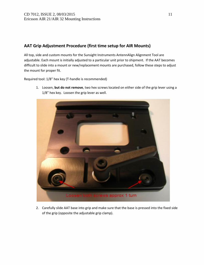
1. Loosen, but do not remove, two hex screws located on either side of the grip lever using a
1/8” hex key. Loosen the grip lever as well.
2. Carefully slide AAT base into grip and make sure that the base is pressed into the fixed side
of the grip (opposite the adjustable grip clamp).
CD 7012, ISSUE 2, 08/03/2015 12
Ericsson AIR 21/AIR 32 Mounting Instructions
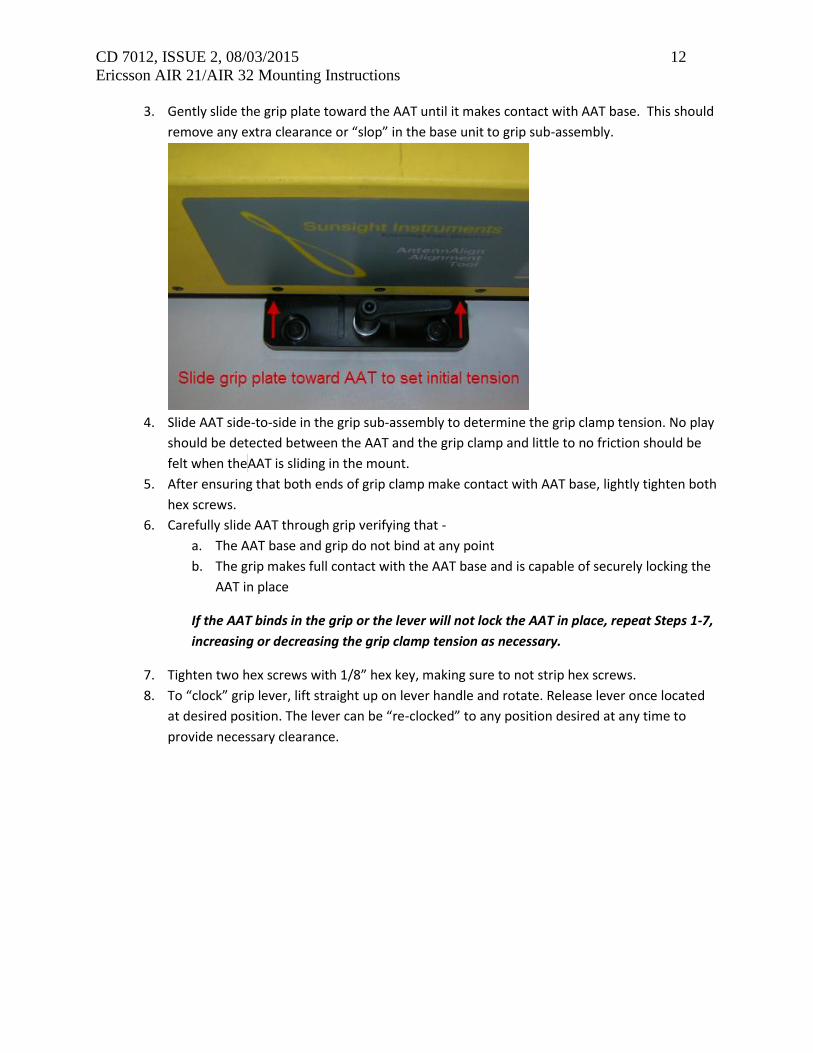
3. Gently slide the grip plate toward the AAT until it makes contact with AAT base. This should
remove any extra clearance or “slop” in the base unit to grip sub-assembly.
4. Slide AAT side-to-side in the grip sub-assembly to determine the grip clamp tension. No play
should be detected between the AAT and the grip clamp and little to no friction should be
felt when the AAT is sliding in the mount.
5. After ensuring that both ends of grip clamp make contact with AAT base, lightly tighten both
hex screws.
6. Carefully slide AAT through grip verifying that -
a. The AAT base and grip do not bind at any point
b. The grip makes full contact with the AAT base and is capable of securely locking the
AAT in place
If the AAT binds in the grip or the lever will not lock the AAT in place, repeat Steps 1-7,
increasing or decreasing the grip clamp tension as necessary.
7. Tighten two hex screws with 1/8” hex key, making sure to not strip hex screws.
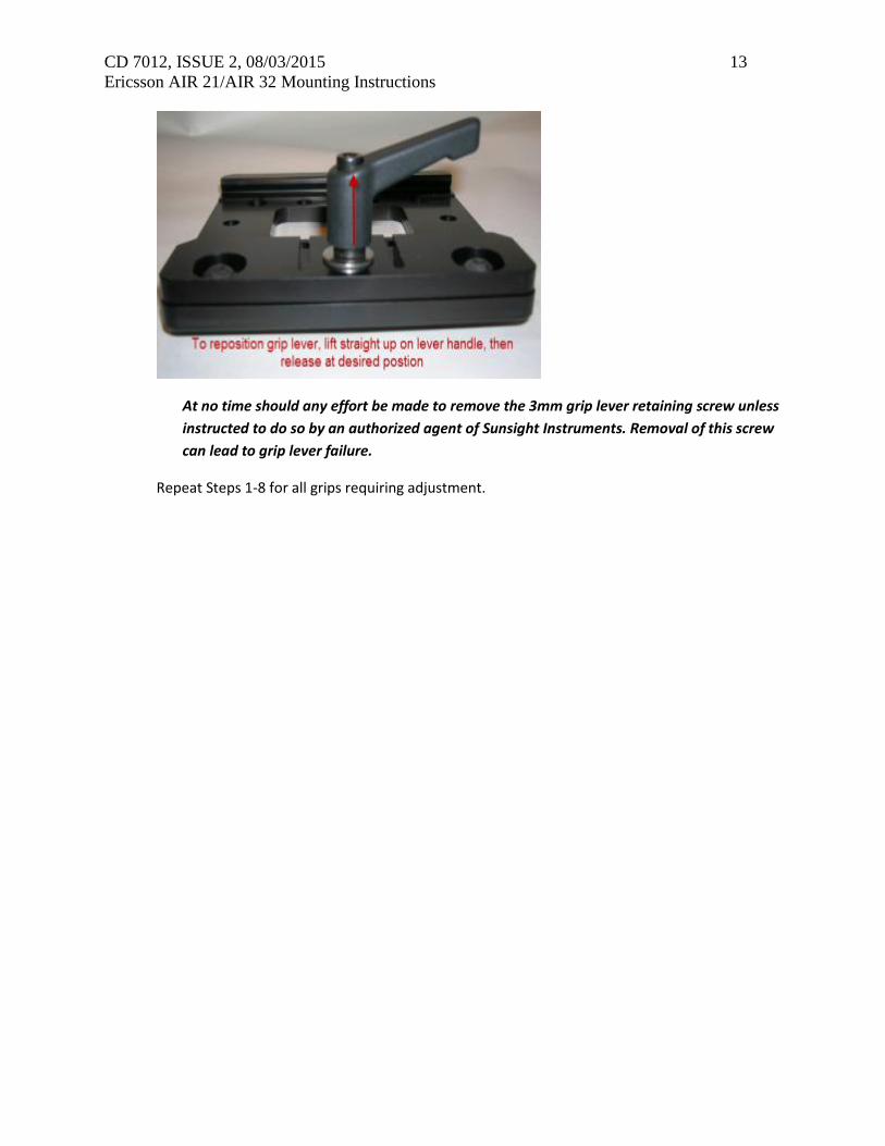
8. To “clock” grip lever, lift straight up on lever handle and rotate. Release lever once located
at desired position. The lever can be “re-clocked” to any position desired at any time to
provide necessary clearance.
CD 7012, ISSUE 2, 08/03/2015 13
Ericsson AIR 21/AIR 32 Mounting Instructions
At no time should any effort be made to remove the 3mm grip lever retaining screw unless
instructed to do so by an authorized agent of Sunsight Instruments. Removal of this screw
can lead to grip lever failure.
Repeat Steps 1-8 for all grips requiring adjustment.