Embed Size (px)
Citation preview

r \ : OMEGA ^ ^ ^ ^ H FiyniiyFFDii\iG i i u r EIMGIIMEERIIMCIIMC.
I n 0>lf."f» t l i r w u p C o m p a n y
MODEL 873 Hand Held Digital Thermometer
Operator's Manual
WARRANTY OI\ EGA warrants this unit to be free of defects in materials and workmanship and to give satisfactory service for a period of one (1) year from date of purchase. If the unit sfiould malfunction, it must be returned to ttie factory for evaluation. Our Customer Service Department will issue an Authorized Return (AR) number immediately upon phone or written request. Upon examination by OMEGA, it the unit is found to be defective it will be repaired or replaced at no charge. However, this WARRANTY is VOID if the unit shows evidence of having been tampered with or shows evidence of being damaged as a result of excessive current, heat, moisture, vibration, or misuse, (Components which wear or which are damaged by misuse are not warranted. These include contact points, fuses, and triacs.
THERE ARE NO WARRANTIES EXCEPT AS STATED HEREIN. THERE ARE NO OTHER WARRANTIES, EXPRESSED OR IMPLIED, INCLUDING BUT NOT LIMITED TO THE IMPLIED WARRANTIES OF MERCHANTABILITY AND OF FITNESS FOR A PARTICUUR PURPOSE. IN NO EVENT SHALL OMEGA ENGINEERING, INC. BE LIABLE FOR CONSEQUENTIAL, INCIDENTAL OR SPECIAL DAMAGES. THE BUYER'S SOLE REMEDY FOR ANY BREACH OF THIS AGREEMENT BY OMEGA ENGINEERING, INC. OR ANY BREACH OF ANY WARRANTY BY OMEGA ENGINEERING, INC. SHALL NOT EXCEED THE PURCHASE PRICE PAID BY THE PURCHASER TO OMEGA ENGINEERING, INC. FOR THE UNIT OR UNITS OR EOUIPMENT DIRECTLY AFFECTED BY SUCH BREACH.
Return Requests/Inquiries Direct all warranty and repair requests/inquiries to OMEGA Customer Service Department, telephone number (203) 359-1660. Before returning any instrument, please contact the OMEGA Customer Service Department to obtain an authorized return (AR) numtier. The designated AR number should then be marked on the outside of the return package.
To avoid processing delays, also please be sure to Include: 1. Returnee's name, address, and phone number. 2. Model and Serial numbers. 3. Repair instructions.
i ^OMEGA A . . ^ H ENGiniEERING, IIMC
One Omega Drive, Box 4047 Stamford, Connecticut 06907-(X)47 (203)359-1660 Telex: 996404 Cable: OMEGA FAX: (203)359-7700
OMEGA'-' is a registered trademark of OMEGA ENGINEERING, INC.
-, Copyright 1984 OMEGA ENGINEERING, INC. Alt rights reserved including illustrations. Nothing in this manual may be reproduced in any manner, either wholly or in part for any purpose whatsoever without written permission from OMEGA ENGINEERING, INC.
Printed in U.S.A. M230/025
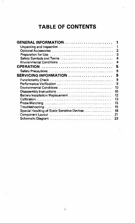
TABLE OF CONTENTS
GENERAL INFORMATION 1 Unpacking and Inspection 1 Optional Accessories 2 Preparation for Use 3 Safety Symbols and Terms 4 Environmental Conditions 4
OPERATION 5 Safety Precautions 6
SERVICING INFORMATION 9 Functionality Check 9 Performance Verification 9 Environmental Conditions 10 Disassembly Instructions 10 Battery Installation/Replacement 12 Calibration 13 Probe Matching 15 Troubleshooting . . . : 15 Special Handling of Static Sensitive Devices 18 Component Layout 21 Schematic Diagram 23
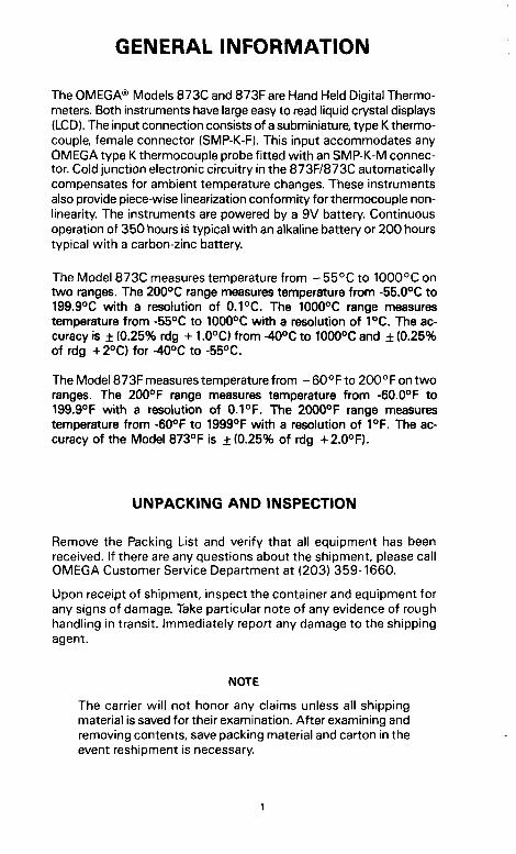
GENERAL INFORMATION
The OI EGA® IVIodels 873C and 873F are Hand Held Digital Thermometers. Both instruments have large easy to read liquid crystal displays (LCD). The input connection consists of a subminiature, type K thermocouple, female connector (SMP-K-F). This input accommodates any OMEGA type K thermocouple probe fitted with an SMP-K-M connector. Cold junction electronic circuitry in the 873F/873C automatically compensates for ambient temperature changes. These instruments also provide piece-wise linearization conformity for thermocouple non-linearity. The instruments are powered by a 9V battery. Continuous operation of 350 hours is typical with an alkaline battery or 200 hours typical with a carbon-zinc battery.
The Model 873C measures temperature from - 55°C to 1000°C on two ranges. The 200°C range measures temperature from -55.0°C to 199.9°C with a resolution of 0.1°C. The 1000°C range measures temperature from -55°C to 1000°C with a resolution of 1°C. The accuracy is ± (0.25% rdg -i- 1.0°C) from -40°C to 1000°C and ± (0.25% of rdg -l-2°C) for -40°C to -55°C.
The Model 873F measures temperature from - 60°F to 200°F on two ranges. The 200°F range measures temperature from -60.0°F to 199.9°F with a resolution of 0.1°F. The 2000°F range measures temperature from -60°F to 1999°F with a resolution of 1°F. The accuracy of the Model 873°F is ±(0.25% of rdg -i-2.0°F).
UNPACKING A N D INSPECTION
Remove the Packing List and verify that all equipment has been received. If there are any questions about the shipment, please call OMEGA Customer Service Department at (203) 359-1660.
Upon receipt of shipment, inspect the container and equipment for any signs of damage. Take particular note of any evidence of rough handling in transit. Immediately report any damage to the shipping agent.
NOTE
The carrier will not honor any claims unless all shipping material is saved for their examination. After examining and removing contents, save packing material and carton in the event reshipment is necessary.
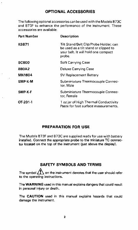
OPTIONAL ACCESSORIES
The following optional accessories can be used with the Models 873C and 873F to enhance the performance of the instrument. These accessories are available:
Part Number
KS871
SC800
880A2
MN1604
SMP-K-M
SMP-K-F
OT-201-1
Description
Tilt Stand/Belt Clip/Probe Holder; can be used as a tilt stand or clipped to your belt. It will hold one compact probe.
Soft Carrying Case
Deluxe Carrying Case
9V Replacement Battery
Subminiature Thermocouple Connector, Male
Subminiature Thermocouple Connector, Female
1 oz jar of High Thermal Conductivity Paste for fast surface measurements.
PREPARATION FOR USE
The Models 873F and 873C are supplied ready for use with battery installed. Connect the appropriate probe to the miniature TC connector located on the top of the instrument (just above the display).
SAFETY SYMBOLS A N D TERMS
The symbol / ! \ on the instrument denotes that the user should refer to the opjerating instructions.
The WARNING used in this manual explains dangers that could result in personal injury or death.
The CAUTION used in this manual explains hazards that could damage the instrument.
ENVIRONMENTAL CONDITIONS
Operation of the Models 873C and 873F should take place at an ambient temperature of -10°C to 50°C (14°F to 122°F), less than 80% relative humidity up to 35°C, lineariy derate 3% R.H./C from 35°C to 60°C.
OPERATION
The 873C and 873F Hand Held Digital Thermometers are easy to use There is only one control (located on the side of the instrument) that turns the instrument on/off and selects the range. (See Figures 1 and 2). Use the following procedure to operate the instrument:
1. Turn on the power to the instrument by selecting the desired range. Model 873C: A. 200°C range is the center position of the ON/OFF range switch. B. 1000°C range is the upper position of the ON/OFF range switch.
Model 873F: A. 200°F range is the center position of the ON/OFF range switch. B. 2000°F range is the upper position of the ON/OFF range switch.
2. Select the appropriate temperature probe and insert it into the input jack.
3. Make the measurement: A. Touch the probe tip to the material to be measured. B. Read the display. The reading is in Celsius for the Model 873C.
The reading is in Fahrenheit for the Model 873F.
NOTE
An open sensor or overrange condition is indicated by:
CAUTION Do not attempt to measure temperatures beyond the range of the probe being used. Probe damage may occur.
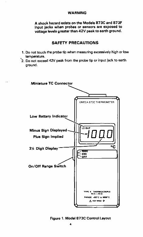
WARNING
A shock hazard exists on the Models 8730 and 873F Input jacks when probes or sensors are exposed to voltage levels greater than 42V peak to earth ground.
SAFETY PRECAUTIONS
1. Do not touch the probe tip when measuring excessively high or low temperature.
2. Do not exceed 42V peak from the probe tip or input jack to earth ground.
Miniature TC Connector
Low Battery Indicator
Minus Sign Displayed •
Plus Sign Implied
3V4 Digit Display—
On/Off Range Switch
OMEGA 873C THERMOMETER
LO BAT
-loao 200
TYPE K THEHMOCOUPLE NiCr-N<AI
RANOE: - I B ' C to lOOO'C
^ 42V MAX -^
Figure 1. Model 873C Control Layout
4
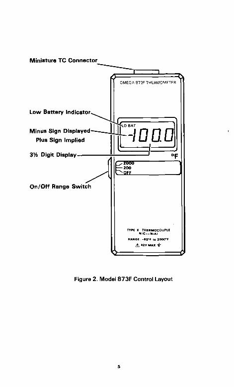
Miniature TC Connector
Low Battery Indicator^
Minus Sign Displayed-
Plus Sign Implied
VA Digit Display-
On/Off Range Switch
OMEGA 873F THEHMOMETER ^
r DM I
-\QO.U ^=
TYPE K THEIIMOCOUPI.E N i C r - N i A l
RANOE. - tO'E to 2000*F
A 42V MAX +
Figure 2. Model 873F Control Layout
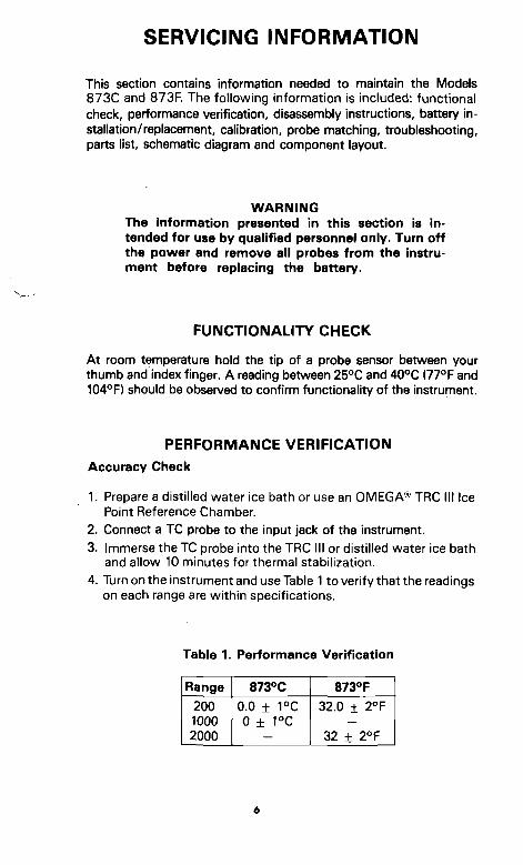
SERVICING INFORMATION
This section contains information needed to maintain the Models 873C and 873R The following information is included: functional check, performance verification, disassembly instructions, battery installation/replacement, calibration, probe matching, troubleshooting, parts list, schematic diagram and component layout.
WARNING The information presented in this section is intended for use by qualified personnel only. Turn off the power and remove all probes from the instrument before replacing the battery.
FUNCTIONALITY CHECK
At room temperature hold the tip of a probe sensor between your thumb and index finger. A reading between 25°C and 40°C (77°F and 104°F) should be observed to confirm functionality of the instrument.
PERFORMANCE VERIFICATION
Accuracy Check
1. Prepare a distilled water ice bath or use an OMEGA* TRC III Ice Point Reference Chamber.
2. Connect a TC probe to the input jack of the instrument. 3. Immerse the TC probe into the TRC III or distilled water ice bath
and allow 10 minutes for thermal stabilization, 4. Turn on the instrument and use Table 1 to verify that the readings
on each range are within specifications.
Table 1. Performance Verification
Range
200 1000 2000
873°C
0.0 ± 1°C 0 ± 1°C
873°F
32,0 ± 2°F
32 ± 2°F
ENVIRONMENTAL CONDITIONS
The Models 873C and 873F should be at an ambient temperature of 23°C ±1°C and a relative humidity of less than 80%.
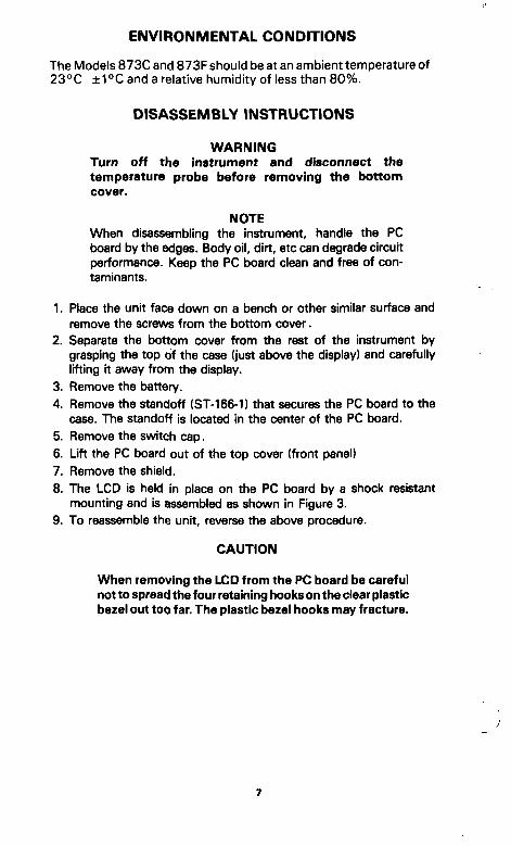
DISASSEMBLY INSTRUCTIONS
WARNING Turn off the instrument and disconnect the temperature probe before removing the bottom cover.
NOTE When disassembling the instrument, handle the PC board by the edges. Body oil, dirt, etc can degrade circuit performance. Keep the PC board clean and free of contaminants.
1. Place the unit face down on a bench or other similar surface and remove the screws from the bottom cover.
2. Separate the bottom cover from the rest of the instrument by grasping the top of the case (just above the display) and carefully lifting it away from the display.
3. Remove the battery. 4. Remove the standoff (ST-166-1) that secures the PC board to the
case. The standoff is located in the center of the PC board. 5. Remove the switch cap. 6. Lift the PC board out of the top cover (front panel) 7. Remove the shield. 8. The LCD is held in place on the PC board by a shock resistant
mounting and is assembled as shown in Figure 3. 9. To reassemble the unit, reverse the above procedure.
CAUTION
When removing the LCD from the PC board be careful not to spread the four retaining hooks on the clear plastic bezel out too far. The plastic bezel hooks may fracture.
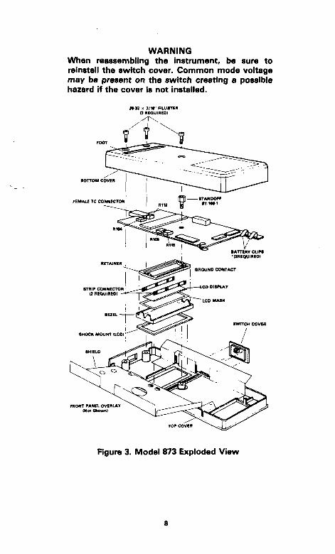
WARNING When reassembling the instrument, be sure to reinstall the switch cover. Common mode voltage may be present on the switch creating a possible hazard if the cover Is not installed.
f U a K 7 / V RLUSTtn a HEQUIRED)
BOTTOM COVER
Figure 3. Model 873 Exploded View
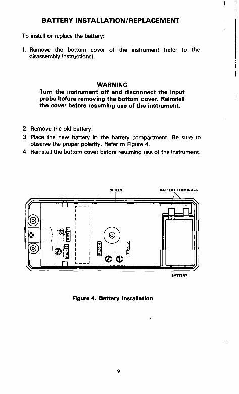
BATTERY INSTALLATION/REPLACEMENT
To install or replace the battery:
1. Remove the bottom cover of the instrument (refer to the disassembly instructions).
WARNING Turn the instrument off and disconnect the input probe before removing the bottom cover. Reinstall the cover before resuming usa of the instrument.
2. Remove the old battery. 3. Place the new battery in the battery compartment. Be sure to
observe the proper polarity. Refer to Figure 4. 4. Reinstall the bottom cover before resuming use of the instrument.
BArrenv TERMINALS
Rgure 4. Battery Installation
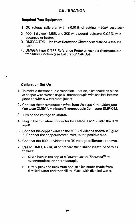
CALIBRATION
Required Test Equipment
1. DC voltage calibrator wrth ±0.01% of setting ±20/iV accuracy
2. 100: 1 divider- 1.98k and 20n wirewound resistors, 0.02% ratio accuracy or better.
3. OMEGA TRC III Ice Point Reference Chamber or distilled water ice bath.
4 . OMEGA type K TRP Reference Probe or make a thermocouple Transition junction (see Calibration Set-Up).
Calibration Set-Up
1. To make a thermocouple transition junction, silver solder a piece of copper wire to each (type K) thermocouple wire and insulate the junction with a waterproof jacket.
2. Connect the thermocouple wires from the type K transition junction to an OMEGA Miniature Thermocouple Connector SMP-K-M.
3. Turn on the voltage calibrator.
4 . Plug in the miniature connector (see steps 1 and 2) into the 873 input.
5. Connect the copper wires to the 100:1 divider as shown in Figure 5. Connect the copper/chromel wire to the positive sida
6. Connect the 100:1 divider to the DC voltage calibrator as shown.
7. Use an OMEGA TRC III or prepare the distilled water ice bath as follows:
A. Drill a hole in the cap of a Dewar flask or Thermos™ to accommodate the thermocouple,
B. Firmly pack the flask with pea-size ice cubes made from distilled water and then fill the flask with distilled water.
10
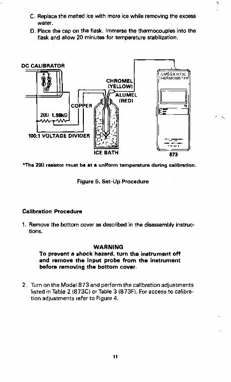
C. Replace the melted ice with more ice while removing the excess water.
D. Place the cap on the flask. Immerse the thermocouples into the flask and allow 20 minutes for temperature stabilization.
DC CALIBRATOR
100:1 VOLTAGE DIVIDER
ICE BATH 873
*The 20(1 resistor must be at a uniform temperature during calibration.
Figure 5. Set-Up Procedure
Calibration Procedure
1. Remove the bottom cover as described in the disassembly instructions.
WARNING To prevent a shock hazard, turn the instrument off and remove the Input probe from the instrument before removing the bottom cover.
2. Turn on the Model 873 and perform the calibration adjustments listed in Table 2 (873C) or Table 3 (873F). For access to calibration adjustments refer to Figure 4.
11
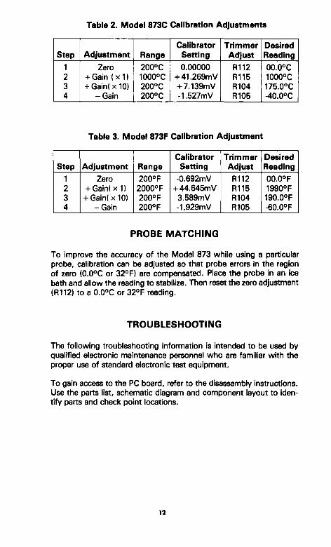
Table 2. Modal 8730 Calibration Adjustments
Step
1 2 3 4
Adjustment
Zero -i-Gain ( x l ) + Gain(x10)
-Gain
Range
200°C 1000°C 200°C 200°C
Calibrator Setting
0.00000 + 41.269mV -H7.139mV -1.527mV
Trimmer Adjust
R112 R115 R104 R105
Desired Reading
00.0°C 1000°C 175.0°C -40.0°C
Table 3. Model 873F Calibration Adjustment
Step
1 2 3 4
Adjustment
Zero -i-Gain(xl) + Gain(x10)
-Gain
Range 200°F 2000°F 200°F 200°F
Calibrator Setting
-0.692mV -i-44.645mV 3.589mV -1.929mV
Trimmer Adjust
R112 R115 R104 R105
Desired Reading
00.0°F 1990°F 190.0°F -60.0°F
PROBE MATCHING
To improve the accuracy of the Model 873 while using a particular proJTe, calibration can be adjusted so that probe errors in the region of zero (0.0°C or 32°F) are compensated. Place the probe in an ice bath and allow the reading to stabilize. Then reset the zero adjustment (R112) to a 0.0°C or 32°F reading.
TROUBLESHOOTING
The following troubleshooting information is intended to be used by qualified electronic maintenance personnel who are familiar with the proper use of standard electronic test equipment.
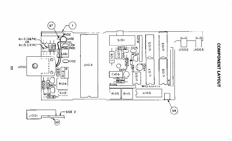
To gain access to the PC board, refer to the disassembly instructions. Use the parts list, schematic diagram and component layout to identify parts and check point locations.
13
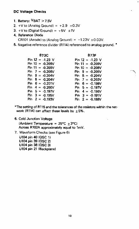
DC Voltage Checks
1. Battery: V B A T > 7 . 5 V
2. -HV to (Analog Ground) = -1-2.9 ±0.3V 3. -fV to (Digital Ground) = +5V ±1V 4. Reference Diode
CR101 (Anode) to (Analog Ground) = -1.23V ±0.03V. 5. Negative reference divider (R114) referenced to analog ground. *
Pin 12 Pin 10 Pin 11 Pin 7 Pin 9 Pin 8 Pin 6 Pin 4 Pin 5 Pin 3 Pin 2
873C = -1.23 V = -0.209V = -0.209V = -0.206V = -0.204V = -0.204V = -0.201V = -0.200V = -0.197V = -0.195V = -0.193V
Pin 12 Pin 11 Pin 10 Pin 9 Pin 8 Pin 7 Pin 6 Pin 5 Pin 4 Pin 3 Pin 2
873F = -1.23 V = -0.209V = -0.208V = -0.205V = -0.204V = -0.203V = -0.198V = -0.197V = -0.196V = -0.191V = -0.188V
*The setting of Rl 15 and the tolerances of the resistors within the network (R114) can affect these levels by ±5%.
6. Cold Junction Voltage (Ambient Temperature = 25°C ±3°C) Across R102A approximately equal to ImV.
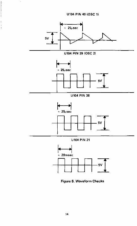
7. Waveform Checks (see Figure 6) U104 pin 40 (OSC 1) U104 pin 39 (OSC 2) U104 pin 38 (OSC 3) U104 pin 21 (Backplane)
13
U104 PIN 40 (OSC 1)
U104 PIN 39 (OSC 2)
H 25|isec
- ^ ' K \ /
U104 PIN 38
K = 25/(sec
5V
U104 PIN 21
M = 20msec
BV
Figure 6. Waveform Checks
14
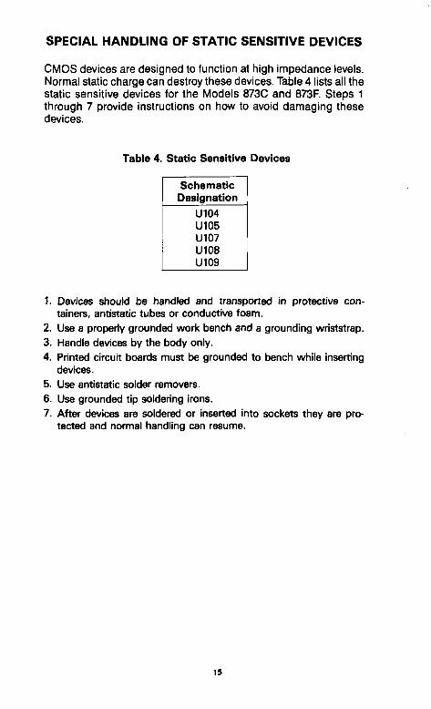
SPECIAL HANDLING OF STATIC SENSITIVE DEVICES
CMOS devices are designed to function at high impedance levels. Normal static charge can destroy these devices. Table 4 lists all the static sensitive devices for the Models 873C and 873F. Steps 1 through 7 provide instructions on how to avoid damaging these devices.
Table 4. Static Sensitive Devices
Schematic Designation
U104 U105 U107 U108 U109
1. Devices should be handled and transported in protective containers, antistatic tubes or conductive foam.
2. Use a properiy grounded work bench and a grounding wriststrap. 3. Handle devices by the body only. 4. Printed circuit boards must be grounded to bench while inserting
devices. 5. Use antistatic solder removers. 6. Use grounded tip soldering irons. 7. After devices are soldered or inserted into sockets they are pro
tected and normal handling can resume.
15
SPECIFICATIONS
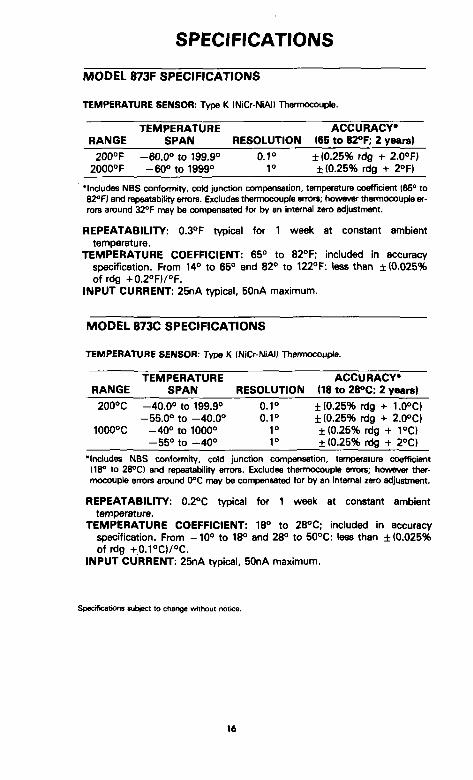
MODEL 873F SPECIFICATIONS
TEMPERATURE SENSOR: Type K INICr-NiAl) Thermocouple,
TEMPERATURE ACCURACY* RANGE SPAN RESOLUTION IBS to SyP; 2 years)
200°F -60.0° to 199.9° 0.1° ±(0,25% rdg -f-2.0°F) 2000°F -60° to 1999° 1^ ± (0.25% rdg -t- 2°F)
•Includes NBS confofmity, coW junction compensation, temperature coefficient 165° to 82<'FI and repeatability errors. Excludes therrtiocouple errors; however thermocouple errors around 32°F may be compensated for by an intemal zero adjustment,
REPEATABILITY: 0.3°F typical for 1 week at constant ambient temperature.
TEMPERATURE COEFFICIENT: 65° to 82°F; included in accuracy specification. From 14° to 65° and 82° to 122°F: less than ±(0,025% of rdg -(-0.2°F)/°F,
INPUT CURRENT: 25nA typical, 50nA maximum.
MODEL 8730 SPECIFICATIONS
TEMPERATURE SENSOR: Type K (Ni&NiAl) Thermocouple,
TEMPERATURE ACCURACY* RANGE SPAN RESOLUTION (18 to 28°C: 2 yeara)
200°C -40.0° to 199.9° 0.1° ± (0.25% rdg -t- 1.0°C) -55.0° to -40.0° 0.1° ±(0.25% rdg -t- 2.0°C)
1000°C -40° to 1000° 1° ±(0.25% rdg -I- 1°C) -55° to - 4 0 ° I f ± (0.25% rdg + 2°C)
"Includes NBS conformity, cold junction compensation, temperature coefficient (18° to 28°C) and repeatability errors. Excludes thermocouple errors; however tfiermocouple errors around 0°C may be compensated for by an intemal zero adjustment,
REPEATABILrrV: 0.2°C typical for 1 week at constant ambient temperature.
TEMPERATURE COEFFICIENT: 18° to 28°C; included in accuracy specification. From -10° to 18° and 28° to 50°C: less than ±(0.025% of rdg -(-0.1°C)/°C.
INPUT CURRENT: 25nA typical, 50nA maximum.
Specifications subject to change without notice.
16
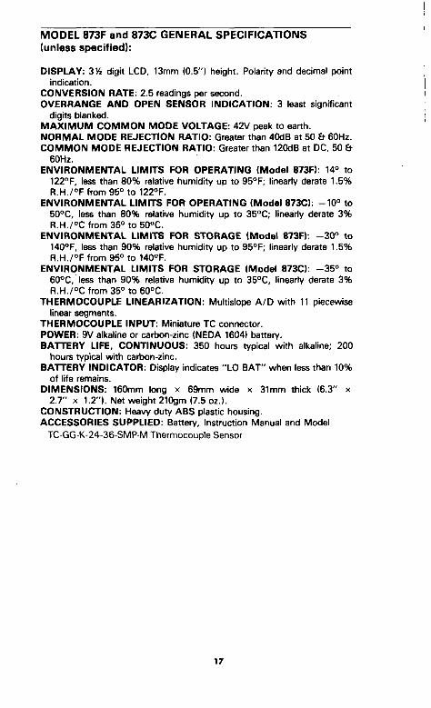
MODEL 873F and 873C GENERAL SPECIFICATIONS (unless specified):
DISPLAY: 314 digit LCD, 13mnfi (0.5") height. Polarity and decimal point indication.
CONVERSION RATE: 2.5 readings per second. OVERRANGE AND OPEN SENSOR INDICATION: 3 least significant
digits blanked, MAXIMUM COMMON MODE VOLTAGE: 42V peak to earth. NORMAL MODE REJECTION RATIO: Greater than 40dB at 50 & 60Hz. COMMON MODE REJECTION RATIO: Greater than 120dB at DC, 50 &
60Hz, ENVIRONMENTAL LIMITS FOR OPERATING (Model 873F): 14° to
122°F, less than 80% relative humidity up to 95°F; lineariy derate 1.5% R.H./°F from 95° to 122°F.
ENVIRONMENTAL LIMITS FOR OPERATING (Model 873C): -10° to 50°C, less than 80% relative humidity up to 35°C; lineariy derate 3% R,H./°C from 35° to 50°C.
ENVIRONMENTAL LIMITS FOR STORAGE (Model 873F): - 30° to 140°F, less than 90% relative humidity up to 95°F; linearly derate 1.5% R,H,/°F from 95° to 140°F,
ENVIRONMENTAL LIMITS FOR STORAGE (Model 873C): - 35° to 60°C, less than 90% relative humidity up to 35°C, linearly derate 3% R.H./°C from 35° to 60°C.
THERMOCOUPLE LINEARIZATION: Multislope A/D with 11 piecewise linear segments.
THERMOCOUPLE INPUT: Miniature TC connector. POWER: 9V alkaline or carbon-zinc (NEDA 1604) battery. BATTERY LIFE, CONTINUOUS: 350 hours typical with alkaline; 200
hours typical wrth carbon-zinc. BATTERY INDICATOR: Display indicates "LO BAT" when less than 10%
of life remains. DIMENSIONS: 160mm long x 69mm vinde x 31mm thick (6,3" x
2.7" X 1.2"). Net weight 210gm (7.5 oz.), CONSTRUCTION: Heavy duty ABS plastic housing. ACCESSORIES SUPPLIED: Battery, Instruction Manual and Model
TC-GG-K-24-36-SMP-f\/l Thermocouple Sensor
17
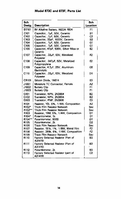
Model 8730 and 873F, Parts List
Sch Desig.
BT101 C101 C102 C103 0104 C105 C106
0107
0108
0109
0110
OR101 J1001 J1002 J1003 Q101 Q102 Q103 R101 R102* R102** R103 R104* R104** R105 R106 R107 R108 R109 R110
R i l l
R112 R113
Description
9V Alkaline Battery, NEDA 1604 Capacitor, .^^lf, 50V, Ceramic Capacitor, .l/iF, 50V, Ceramic Capacitor, 33pF, 1000V, Ceramic Capacitor, .VF, 50V, Ceramic Capacitor, .IjjF, 50V, Ceramic Capacitor, 47pF, 500V, Silver Mica or Ceramic Capacitor, .33f»F, 63V, Metalized Polyester Capacitor, .047^F, 50V, Metalized Polypropylene Capacitor, 4.7/JF, 25V, Aluminum Electrolytic Capacitor, .33MF, 63V, Metalized Polyester Silicon Diode, 1N914 Miniature TC Connector, Female Battery Clip Battery Clip Transistor, NPN, 2N3904 Transistor, NPN, 2N3904 Transistor, PNP, 2N3906 Resistor, 10k, 5%, 1/4W, Composition Thick Film Resistor Networic Thick Rim Resistor Network Resistor, 10M, 5%, 1/4W, Composition Potentiometer, Ik Potentiometer, 50012 Potentiometer, 2k Thick Film Resistor Network Resistor, 191k, 1%, 1/8W, Metal Film Resistor, 390k, 5%, 1/4W, Composition Thick Film Resistor Network Factory Selected Resistor (Part of A31419) Factory Selected Resistor (Part of A31410) Potentiometer, 2k Factory Selected Resistor (part of A31419)
Sch Location
Fl Bl C2 82 G1 G1 E2
F2
E2
G5
Dl
E3 A2 Fl Fl B2 82 E3 A2 Sev Sev Dl Dl Dl D2 Sev F2 F2
Sev 83
83
83 C3
18
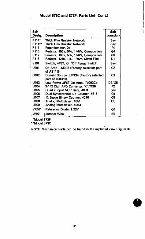
Modei 873C and 873F, Parts Ust (Cont.)
Sch Desig.
R114* RIM"" R115 R116 R117 R118 S101 U101
U102
U103 U104 U105 U106 U107 U108 U109 VR101 W101
Description
Thick Film Resistor Network Thick Film Resistor Networi< Potentiometer, 2k Resistor, 100k, 5%, 1/4W, Composition Resistor, 100k, 5%, 1/4W, Composition Resistor, 121k, 1%, 1/8W, Metal Film Switch, 4P3T, On/Off Range Switch Op Amp, LM308 (Factory selected; part of A31419) Current Source, LM334 (Factory selected; part of A31410) Low Power JFET Op Amp, TL062Cp 3-1/2 Digit A/D Converter, ICL7136 Quad 2 Input NOR Gate, 4001 Dual Synchronous Up Counter, 4518 12 Stage Binary Counter, 4020 Analog Multiplexer, 4051 Analog Multiplexer, 4053 Reference Diode, 1.23V Jumper Wire
Sch Location
Sev Sev F4 G4 86 Dl Sev C2
03
D2/G5 F2
Sev 05 05 D5
G5 85
•Model 873F "Model 8730
NOTE: Mechanical Parts can be found in the expk>ded view (Figure 3).
•
19
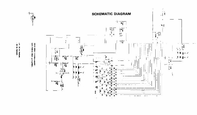
+T] SCHEMATIC DIAGRAM
! «f;r
a = » a
il ir^
i
8
*i
^ ^
^""
t iM
I 11
' ^ H -
15 » i -
5 » I
RII3(2fe7K)_ OR
R I I 3 ( I 2 I K ) -
•o JIOOI
CIO! ED
(ZDCI02
JIOOI
" ^ ^
SIDE 2
SIOI
C109' 5 H-y > C106 Q
iftiilj— RIQ&
Rmz>
O
00 O
WIOl
RIGS RI I5 U I 0 6
n 1 n n
JIOO2 J I003
o o TJ o z m
5 < O c

ut

OiVIEGA^... YOUR SOURCE FOR
SENSING AND CONTROL
This is the FREE complete reference book you will want to keep within reach at all times. Send for your LATEST COPY now!
One Omega Drive, Box 4047 Stamford, CT 06907-0047 (203)359-1660 Telex: 996404 FAX: (203)359-7700
Phone: (203)359-1660
HMDilOOKAiio BIEYiaOFEIllA
/ ^ O M E G A l A ^ . A H ENGiiUEERiNG. IIMC. A n OIWEGA Group Company
"The WORLD'S Leader in the Field of Sensing and Control"
n Thermocouple Probes and Assemblies D Industrial Thermocouple Assemblies n Infrared and Hand Held Instruments D Hand Held and Surface Thermocouple Probes n RTD Probes and Assemblies D Thermistor Probes and Assemblies D Connector Systems and Panels a Wire: Thermocouple, RTD and Thermistor D Cements, Coatings and Epoxles n Calibrators and Ice Point References D Analog Meters and Amplifiers D Digital Thermometers D Temperature and mV Recorders n Solid State Controllers and Relays D Digital Process Monitors D Data Acquisition Modules and Data Loggers D Computer Sensor Interface D Technical and Reference Books
Return Requests/Inquiries
Direct all warranty and repair requests/inquiries to OMEGA Customer Service Department, telephone number (203)359-1660, Before returning any instrument, please contact the OMEGA Customer Service Department to obtain an authorized return (AR) number. The designated AR number should then be marked on the outside of the return package.
To avoid processing delays, also please be sure to include: 1. Returnee's name, address, and phone number. 2. Model and Serial numbers. 3. Repair instructions.
jncOMEGA i ^ . A H ENGINEERING, INC. One Omega Drive, Box 4047 Stamford, CT 06907-0047 (203)359-1660 Telex: 996404 Cable. OMEGA FAX: (203)359-7700