Embed Size (px)
Citation preview
" != NOLTR 63-19
CALIBRATION FOR THE GAP TEST WITH
S" o I A PENTOLITE DONOR
hREEASiD TO ASTIA$Y•E £NAVAL G:"NANCi LABORATOY
* Wi'Tlthout restrictions•For Releae to Military and Government
•-- • A;ýenc it!,; Only.
C-7' L•[ Approv:ij iy Ruwcp3 required for release:-" 0I : to cantr 'icturs.
Approval by Bulveps required for alloubsequent release.
~ Q9 JANUARY 1963A
UNITED STATES NAVAL ORDNANCE LABORATORY, WHITE OAK, MARYLAND
I0
I--
z
NOLTR 63-19
CALIBRATION FOR THE GAP TEST WITH A PENTOLITE DONOR
By
I. JaffeG. RobersonJ. Toscano
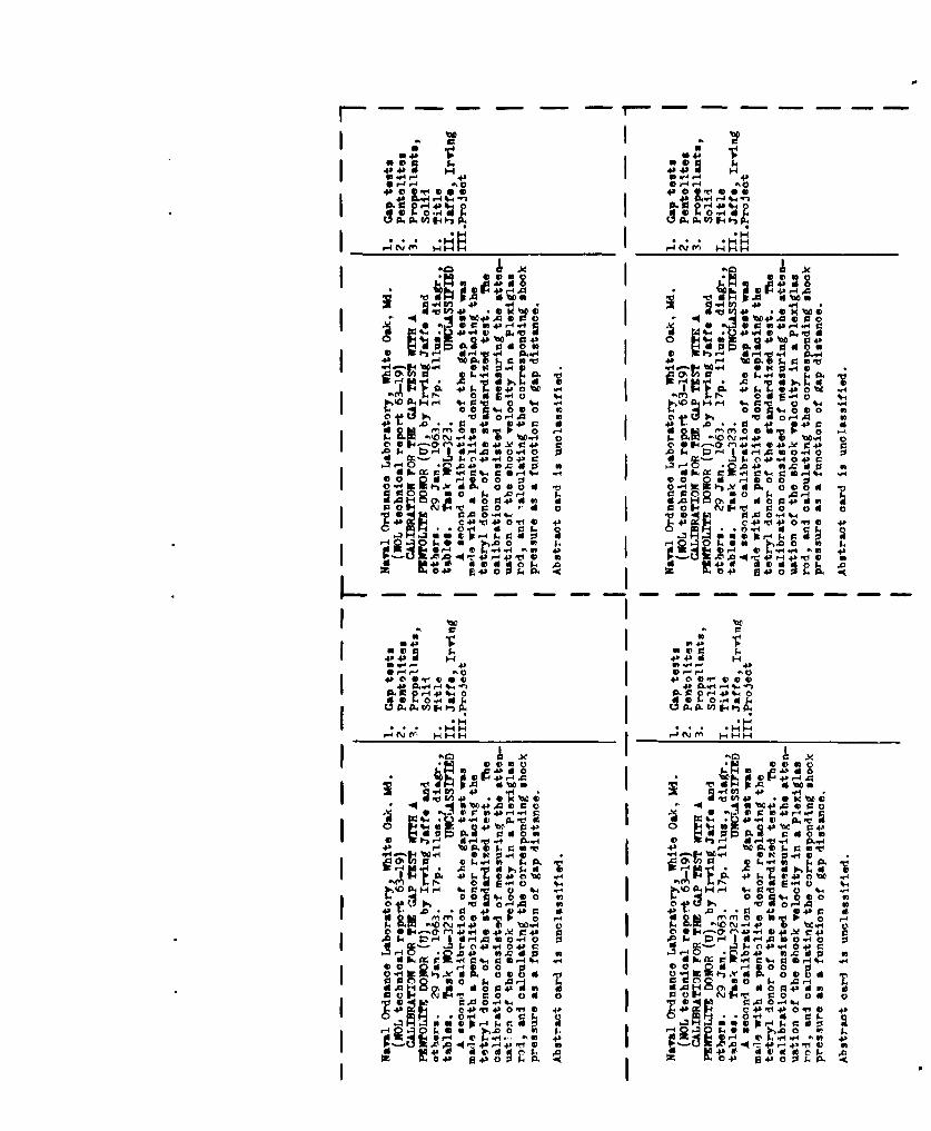
ABSTRACT: A second calibration of the gap test was made witha pentolite donor replacing the tetryl donor of the standard-ized test. The calibration consisted of measuring theattenuation of the shock velocity in a Plexiglas rod, andcalculating the corresponding shock pressure as a function ofgap distance.
APPROVED BY: Carl Boyars, ChiefPhysical Chemistry Division
CHEMISTRY RESEARCH DEPARTMENTU. S. NAVAL ORDNANCE LABORATORY
WHITE OAK, SILVER SPRING, MARYLAND
NOLTR 63-19 29 January 1963
This report supersedes NOLTR 62-78 of 15 May 1962.
The work reported here was carried out under Task NOL-323,Polaris Program on the Sensitivity of Solid Propellants. Thecalibration of the shock sensitivity test (Sap test) with adonor which is readily available (pentolite) increases theusefulness and availability of the test. At the same time, theresults which have been obtained with the tetryl donor arerelevant and may be correlated with a fair degree of confidencewith the results attainable with the new donor. The pentolitedonor described has been adopted by the Armed Services ExplosivesSafety Board as the standard donor to bc used in the hazardclassification of solid propellants.
R. E. ODENINGCaptain, USNCommander
ALBERT LIG1IýBODYBy direction
ii
NOLTR 63-19
TABLE OF CONTENTS
Page
Introduction ........................... 1Experimental . .... . ... .... . .. .... . ..... . . . ....... 1Results ..... •••.. . .••••••. . . ... ...... •o .. . . 3Discussion .................. o......................o...... 7Appendix I - Analytical Reduction of the P vs X Data .... 15References .... . ........... . ............. ... * * . ** * .. .... 17
TABLES
Table I Distance vs Time in Plexiglas Rod ......... 5Table II Pressure and Shock Velocity as a Function
of Distance ..... ...***** .. .** * . ... . ..* . 12Table III Pentolite vs Tetryl - Shock Sensitivity ... 13Table AI Comparison Between the Experimental Data
and the Analytical Results .............. 16
FIGURES
Figure 1 Experimental Set-Up ....................... 2Figure 2 Smear Record of Shock in Plexiglas Rod ... 4Figure 3 Shock in Plexiglas ........................ 6Figure 4 Pressure vs Gap (Graph.)................... 9Figure 5 Pressure vs Gap (Anal.)................... 10Figure 6 Log P vs X ... . ........ o.............*. 11
iii
NOLTR 63-19
CALIBRATION FOR THE GAP TEST WITH A PENTOLITE DONOR
I. INTRODUCTION
The NOL large-scale shock sensitivity test (gap test) wasoriginally calibrated with a tetryl donor (1) to interpret the50% point gap in terms of absolute pressure. The pressureamplitude at the 50% point, assuming the shape of the pressurepulse to be defined by the amplitude, should be an intrinsicproperty of a propellant tested under standardized conditions,and should be reproducible regardless of the donor used. Todetermine the validity of this assumption a standard pentolitedonor was made and used in a second calibration. This donorwas also used to determine the 5! point of various substances;the pressures obtained at the 50% point were compared to thoseobtained with the standard tetryl donor.
II. EXPERIMENTAL
A. Pentolite Donor
The chemical and physical properties of trinitro-toluene (TNT-Grade I) and pentaerythrite tetranitrate (PETN),which were used to formulate pentolite, are specified in theJoint Army-Navy Specification (2,0). A quantity of theseingredients were sieved separately, using a No. 70 and a No. 100sieve (U.S. Standard Sieve Series - ASTM specification). Thatfraction of material which passed the No. 70 sieve and remainedon the No. 100 sieve (particle size ranging from 150 microns to210 microns) was used. One thousand grams of the sieved TNT andan equal amount of PETN was added to a "V"-blender and dryblended for a period of one hour to insure a homogeneous mixture.
The TNT-PETN mixture (pentolite) was placed in a mold, whichmeasured 2 inches inside diameter, and was pressed on a hydrau-lic press to a length of 1 ± 0.003 inches and to a density of1.56 - 1.57 g/cc which is 91 - 92% of the theoretical maximumdensity, 1.71 g/cc.
B. Experimental Procedure
The attenuation of a shock generated by two pentolitepellets in a Plexiglas rod was measured by a streak camera.Figure 1 is a schematic of the experimental assembly. A
1
NOLTR 63- 19
0
4,o 0u zj
Li DU hi
zz z-0U0 w
In-hi
zw
lco w
w
hiL
-JJ
0.'CL&J
2
NOLTR 63-19
Plexiglas rod 2 inches in diameter and 4 inches long wasmachined from 1 7/8 inches sheet Plexiglas. The resultingrod contained two parallel opposing flat surfaces 1 7/8 inchesapart (see Figure 1) through which the camera could view theshock front as it progressed up the rod. The flat surfaceseliminate any distortion of the light. Calibration lines wereinscribed at known distances on the rod.
The rod was set upon two pentolite pellets which were condi-tioned at 250C. A blast shield of known thickness wasprovided to prevent the products of the reaction, resultingfrom the detonating pentolite pellets, from obscuring the viewof the camera. A detonator, used to initiate the reaction, wasplaced in contact with the donor. The entire assembly was back-lighted by an exploding wire. The approximate speed of thecamera was 1.32 nm per microsecond.
III. RESULTS
Figure 2 is a typical record (Expt. No. 2) taken from theseries of four experiments performed. The data obtained fromthese records are listed in Table I and plotted in Figure 3.
The equation which relates the shock pressure and theshock velocity is
0
P = PouU
where
P = shock pressurePo= initial density of the material
u = particle velocity
U = shock velocity
To determine a corresponding pressure both the shock velocityand particle velocity must be known. The shock velocity andparticle velocities for Plexiglas (4, 5) and similar substan-ces such as Lucite (1, 6) and Perspex (7) have been determinedexperimentally. These data were combined to give a relation-ship between shock velocity and particle velocity (1) which wasused to calculate a corresponding pressure for each shock veloc-ity determined experimentally under the conditions describedabove.
35
NOLTR 63 -19
4-.---30NVi SiC
wLLw
*1w
00
4
NOLTR 63-19
N n ~C\U0 n0 K'\ CO n
4-) Lýc ý ý C
H 0Ojtc\-H n0 - oi ONC0
a)0 o iIc H U -t Q$) co -
0=0 H0 0 oO\' H co LL(\" n K
H
E a) n fcO~-H H\1 O\ C\j tý-cH ri w)
bo E4 L r ýL -HC;tr\ ý-0-i Cý tr6
Cd
E-4 cm 0
V)
E4± ~ ~ t ---T t-0U\0s(1) HHHC\J 0U\1
tl-00 t K\ Ct
4.) 0C rU CU t:_ t-
4-'ri () * *- n *) *l ý 0
5
NOLTR 63-19
110
100 0
80-
40-
20
0 6 12 Is 24 30
TIME ( MICROSEC )
FIG. 3 SHOCK IN PLEXIGLAS
z6
NOLTR 63-19
It is difficult to determine the velocity precisely forthe first ten to fifteen millimeters of the gap. A slightchange in the interpretation of the data in this region (shapeof the curve) makes for a fairly large change in the calculatedshock pressure. The error may be compounded further by theinaccuracies in the determination of the slope and in theequation of state used to obtain the shock pressure. To obtainthe best interpretation, the shock velocities were obtainedgraphically from the distance-time curve (Figure 3) and com-pared to the velocities obtained from a number of equationsranging from a second to a seventh degree polynomial which werefitted in turn to the experimental data by an electronic com-puter (IBM-7090). A fifth degree equation was obtained whichreproduced the experimental data to a fair degree of accuracy.A more detailed discussion of the equation is given in theappendix.
Figures 4 and 5 are plots of Pressure vs Distance forPlexiglas in which the curves obtained by both methods are com-pared to an analogous curve obtained with tetryl. The tetrylcurve of Figure 4 was derived from graphical treatment of thedata because an analytically fitted cubic in the range 5 - 25psec gave velocities only a few percent higher than thosedetermined graphically (1).
IV. DISCUSSION
The gap used in the NOL shock sensitivity test is composedof Plexiglas, Lucite, cellulose acetate or some combination ofthese materials. These substances are quite similar and it hasbeen demonstrated (1) that they are equivalent as attenuatorsin the gap test. Figures 4 and 5 show the relationship betweenpressure and distance (gap) for both pentolite and tetryl.Both donors were calibrated under similar conditions with oneexception: the Plexiglas rod used here was slightly smaller,1 7/8 inches between the flat parallel surfaces as against twoinches in the earlier work with tetryl. This should not affectthe results obtained to any noticeable degree. The same equa-tion of state was used in both calibrations to calculate thepressure-distance relationship for the gap.
It is apparent that the pentolite donor initially gener-ates a larger pressure (using either pentolite curve) than thetetryl. It is somewhat improbable that the initial pentolite
7

NOLTR 63-19
pressure amplitude would be larger by a factor of two than thatof the tetryl; this casts some doubt on the validity of theupper part of the curve constructed with graphically determinedvalues of U. Moreover the variation of shock pressure withdistance represented by the analytical curve is a more reason-able one compared with the tetryl curve. This similarity in thegeneral configuration of the curve is evident in Figures 4, 5,and 6 (log P vs X). In Fig. 6, curves are shown for Tetryl(log P vs X, linear) and for pentolite, the analytical polynom-ial. In addition, the unconnected data points are shown forpentolite. In the tetryl work (1) the data points fell belowthe extrapolated linear log P vs X curve at values of X lessthan about 18.5 mm. This is not the case for pentolite. Thegraphical and analytical curves are both non-linear and inter-sect at about 5.0 mm; for smaller X the data points are abovethe analytical curve.
Table II contains the smoothed data for the shock veloci-ties and the shock pressures obtained by both methods. Thedegree to which the calculated shock pressure depends upon thevelocity (slope of X-t curve) and the equation of state forPlexiglas can be seen by comparing the shock velocities andthe corresponding calculated shock pressures at 2 millimeters.For a 5% change in velocity there is a 15% difference in theshock pressure, which is due primarily to the difference inparticle velocity (2.3 compared to 2.1 mm/nsec) used to calcu-late the shock pressures. It is believed that the analyticalapproach minimizes the inherent inaccuracies involved in thegraphical interpretation of the data at this point, and shouldbe used to represent the pressure for the first 30 mm of thePlexiglas. Beyond this point both methods give essentially thesame results.
The larger pressure generated by the pentolite donor isattenuated rapidly. After 10 mm it is within the tetryl pressurerange and after 25 mm (1 inch) of travel its curve is similar tothat of the tetryl. From this point on both donors may be con-sidered to give the same pressure amplitude within the precisionof the experimental data.
The pressure amplitude at the 50% point as a quantitativemeasure of sensitivity was further studied by making a seriesof shock sensitivity tests on several different materials. Anumber of charges were made from the same batch of materials andthe 50% point gap was determined using first a tetryl donor andthen a pentolite donor. The results are listed in Table III.
8

NOLTR 63-19
I80
140
to00 PENTOLITE (GRAPH.)
w
mC. 60
20 -TETRYL
0 20 40 0 stoDISTANCE (noB)
FIG. 4 PRESSURE vs GAP
9
NOLTR 63-19
%80-
140
too PENTOLITE (ANAL.)
In
w 6O-
In
TETRYL
20-
0 20 40 60 80 100DISTANCE (mm)
FIG. 5 PRESSURE vs GAP
I0
NOLTR 63-19
200
0
\0
PENT0LITE (GRAPH.)I00-
NOt
60 0 Pf.NTOLITE (ANAL.)
1 40-wi 0
wa: TETRYLa. 0
20-
I I I I I I I0 10 20 30 40 50 60
DISTANCE (mm)
FIG.6 LOG P vs X
II
NOLTR 63-19
TABLE II
Pressure and Shock Velocity as a Function of Distance
Distance Shock Velocity Pressuremm mm/Isec kbar
Graph Analytical Graph Analytical
2 6.13 5.82 169.3 146.15 5.54 5.52 126.8 125.9
7 5.24 5.33 108.2 114.1
10 4.87 5.08 86.8 99.1
12 4.67 4.92 75.5 89.514 4.50 4.76 66.9 80.9
16 4.37 4.63 60.9 73.6
20 4.16 4.38 51.1 61.324 4.01 4.16 44.0 51.228 3.89 3.98 39.5 43.032 3.79 3.82 35.3 36.740 3.58 3.57 27.9 27.548 3.41 3.37 22.1 20.660 3.18 3.18 14.6 14.670 3.03 3.06 10.7 11.0
80 2.93 2.97 8.0 8.990 2.86 2.90 6.1 7.3
100 2.82 2.84 5.3 5.7
12
NoLTR 63-19
F4 . '1 HK
:3 -4 4J-0 o C' co b-02 cd
Go 4 p koC) K K HH. H 1 c -4
q43
H 02
44).) 4-1
E-4 HH r-4H4) 0 04. 04)E4 0 4)3 4-1 4.
04.)
x
'dO
Cdaag)
4-) HP
0- 0
13
NOLTR 63-19
The pressure amplitude for the same substance measured bythe tetryl system and the pentolite system differ by + 5% forgaps larger than 50 cards (13 mm). For gaps less than 50 cardsthe values differ by ± 13 to 20%, with increasing difference fordecreasing gap length (see Table III).
It can be concluded that the same initiating pressure (towithin 5%) is measured by either donor at large gaps. Forsmaller gaps, agreement between the donors is not obtainedbecause the calibration curves in this re ion are inaccurate orbecause the pressure-time loading curves (not measured) affectthe results or because both of these factors are operative.For the smallest gaps (highest pressures) it seems that thepressure-time histories of the two donors differ, and that thisfactor is having a major effect on inducing detonation of theacceptor. In other words, at the highest pressures, pressureamplitude alone does not sufficiently define the shock.
14
NOLTR 63-19
APPENDIX I
The Analytical Reduction of the P vs X Data
The equation determined analytically from the experimentaldata relating distance and time is:
X = 0.377 + 5.903t - 0.250t + 0.012t 3 - 0.297 x l103t 4 +
0.281 x 10'50
where
X = distance (mm)
t = time (iLsec)
The velocity was obtained from the first derivative of theabove equation.
= dx 5.90 - 5.00t + 0.036t 2 - 0.119 x 10⁻² t3 +
0.141 x 10⁻⁴t4
Table AI contains a comparison between the smoothed experi-mental data, and the data calculated by the equation for theinitial 60 mm of Plexiglas. Also in the table are the velocitiescalculated from the equation for the corresponding time. Theequation obtained for the tetryl donor (1) gives a more precisefit than the equation for pentolite obtained in the presentinvestigation. To arrive at the equation for tetryl, the datafrom the single best experiment were used, while for pentolitethe data from all four experiments were used. In this respect,one would assume the equation for pentolite to be a moreaccurate description of P vs X than the equation for tetryl.
15
NOLTR 63-19
TABLE AI
Comparison Between the ExperimentalData and the Analytical Results
Experimental Calculated
Time Distance Distance Velocitymm/4sec mm mm mm/ýisec
1.00 5.98 6.04 5.442.00 11.50 11.28 5.043.00 16.20 16.14 4.70
4.00 20.70 20.69 4.415.00 24.90 24.98 4.17
6.oo 29.00 29.05 3.977.00 32.90 32.94 3.81
8.00 36.70 36.68 3.679.00 40.30 40.30 3.5710.00 43.70 43.82 3.4811.00 47.20 47.26 3.41
12.00 50.60 50.65 3.3613.00 54.10 53.98 3.32
14.00 57.40 57.28 3.2815.00 60.70 60.55 3.25
16
NOLTR 63-19
REFERENCES
1. I. Jaffe, R. L. Beauregard and A. B. Amster, "TheAttenuation of Shock in Lucite", NavOrd Report 6876,27 May 1960. Unclassified.
2. Joint Army-Navy Specification, "Trinitrotoluene (TNT)",JAN-T-248, Navy No. 5172C, 29 September 1945.
3. Joint Army-Navy Specification "Pentaerythrite Tetranitrate(PETN)", JAN-P-387, Navy No. 4 1 2, 29 August 1946.
4. N. L. Colburn, "The Dynamic Compressibility of Solids fromSingle Experiments Using Light Reflection Techniques",NavWeps Report 6026, 31 October 1960.
5. M. A. Cook, R. T. Keyes, and W. 0. Ursenbach, ONR Symposium
Report ACR-50, 2, 357 (1960).
6. Los Alamos Scientific Laboratory: Private communication.
7. J. S. Buchanan, H. J. James and G. W. Teague, ArmamentResearch and Development Establishment, ARDE MEMO (MX)20/59, April 1959.
17
NOLTR 63-19
DISTRIBUTION
No. ofCopies
SPIA (Distribution List) .............................. 100Chief, Bureau of Naval Weapons
Washington 25, D.C.Attn: Library (DLI-3) .............................. 1Attn: SP-271 ...................... 4..................... 4Attn: SP-20 ............. o 4.. *... ... 44.... ... **4.. . . 1Attn: SP-27 - o....................................... 1
Attn: RMMP........................................ 3Attn: F-12 o...... o....... . .... a.. ..... ..... ........ 1Attn: RUME-32, E. M. Fisher ........................ 1Attn: RUME-33, G. C. Edwards ....................... 1
Office of Naval Research, Washington 25, D.C.Attn: Power Brinch (Code 429) ...................... 2
Commander, U.S. Naval Propellant Plant, Indian Head, MdAttn: Code K ........................ .......... .... o....... 1
Aerojet-General Corporation1711 Woodruff Avenue, Downey, CaliforniaAttn: Dr. L. Zernow ..... 00..........................
Aerojet-General CorporationP.O. Box 1168, Sacramento, CaliforniaAttn: Dr. W. Kirchner . .......................... * . . 4
Lockheed Missiles and Space CompanyA Division of Lockheed Aircraft Corporation1122 Jagels Road, Sunnyvale, CaliforniaAttn: Mr. J. Lightfoot ......... .............. 3
Bureau of Naval Weapons Representative(Special Projects Office)Lockheed Missiles and Space CompanyP.O. Box 504, Sunnyvale, CaliforniaAttn: SPL-513 .. . . . .. . . .. .. . . . . . . . 2
Bureau of Naval Weapons Resident Representative(Special Projects Office)Aerojet-General CorporationSacramento, CaliforniaAttn: SPLA-30 .... .................................. *
Bureau of Naval Weapons RepresentativeAllegany Ballistics LaboratoryCumberland, MarylandAttn: SPH-50 ............................ . .......... 2
Allegany Ballistics LaboratoryHercules Powder CompanyCumberland, MarylandAttn: Dr. N. F. LeBlanc ............................ 2Attn: Mr. R. Richardson ..* . 4............* ... ....... 2
NOLTR 63-19
DISTRIBUTION LIST (Cont'd)
No. ofCopies
AeronutronicsA Division of Ford Motor CompanyFord Road, Newport Beach, CaliforniaAttn: Mr. S. Weller ............................... 3
Mr. M. Boyer .......... . . .. . . . . . .. 1
Rohm and Haas CompanyRedstone ArsenalHuntsville, AlabamaAt tn: Dr . H°. S huey .. ....... .... .. .. ... 3
Commander, U.S. Naval Ordnance Test StationChina Lake, CaliforniaAttn: Code 453 .......... . . .. . . .. .. .. . 2
Attn: Code 5008 ............... 1Armed Services Explosives Safety Board
Building T-7, Gravelly PointWashington, D.C.Attn: Mr. R. C. Herman ... 1..........................
Stanford Research InstituteLiquid Propellant DepartmentPropulsion Sciences DivisionMenlo Park, CaliforniaAttn: Dr. A. B. Amster ............................ 3
U.S. Bureau of Mines4800 Forbes Street, Pittsburgh 13, PennsylvaniaAttn: Dr. C. M. Mason ................ 99....... ..... 1
Director, Office of the Secretary of DefenseAdv. Res. Proj. Agency, Washington 25, D.C.Attn: Dr. John F. Kincaid ... 1.......................
University of Cal. Lawrence Radiation LaboratoryP.O. Box 808, Livermore, CaliforniaAttn: Dr. G. Dorough ..................... .......... 1
Los Alamos Scientific LaboratoryP.O. Box 1663, Los Alamos, New MexicoAttn: Dr. L. C. Smith ............................. *. 1
Liquid Propellant Information AgencyThe Johns Hopkins UniversityApplied Physics Laboratory8621 Georgia Avenue, Silver Spring, MarylandAttn : Library ......... .... .... .. .... 25
Space Technology LaboratoryP.O. Box 95001, Los Angeles 45, CaliforniaAttn: Mr. H. A. Taylor ............................. 1
VIANavy Liaison Office (SP), AFU P.O., Los Angeles, CalifAttn: M. H. Holt ..... ....... ... .......... .......06 0** 1
E-
00
0 r
8
0
I- U
-~ I-r-z0 0
0~~~r u00 U ~0
uI 0. 00. L
IO SO -. j J 2,-, O
0
Jo) 00 -M
olJ 0
0 . C
a0
*r4
.ri.
I.JON F : t0
z a 0I- FL
0.z
0. 30Ir44 r-40 Le 4) s
0-d 4 4 'o U -H 4 -%O
F 0 .,HId4 51 0 4
40 I f -a'I
0 r- w
aO 04': '
-CO ck V) 0 h4))I9 d*- .Kv 0~ %4 vo. I
n*0 em 0 0- 0. v -s
'o 0 cc)94-& d n 4O o -P do NV m1
0. 0P0- r-0 4 01.4% -
d o 1d 0 0d.0 Od d .0
-C41+b)OqlO 4s
I IAn~30 0 . ,1
4) W .4 -I 4A
0 0flie )~ '10 -a0cll a4
3 * 4 log ,44-0 d 600 W
4&
ok 041
-4 0% In 1
-0 30 S.C-43
3.54.4 53 4ra 's I 4rS.-