Embed Size (px)
Citation preview
/
TWR-16417
CSHUITLE
EVALUATION OF A METERING, MIXING, AND DISPENSING
SYSTEM FOR MIXING POLYSULFIDE ADHESIVE
FINAL REPORT
JUNE 1989
Prepared for:
NATIONAL AERONAUTICS AND SPACE ADMINISTRATION
GEORGE C. MARSHALL SPACE FLIGHT CENTER
MARSHALL SPACE FLIGHT CENTER, ALABAMA 35812
Contract No. NAS8-30490
DR. No. Type 5-3
WBS.No. HQ 301
-MORTON THIOKOL INC.
AerOspace Group
Space OperationsRO. Box 707, Brigham City, Utah 84302-0707 (801) 863-3511
FORM TC 4677 iREV 1-88)
(NASA-CR-183749) EVALUATION OF A METERING,
MIXING, AND DISPENSING SYSTEM FOR MIXING
pOLYSULFIOE AOHF3IVF Final Report (Morton
Tbiokol) 26 P CSCL IIC G3/Z7
N90-13654
Uric 1 as
https://ntrs.nasa.gov/search.jsp?R=19900004338 2018-06-04T14:04:40+00:00Z
• DOC NO.
TITLETWR-16417
2032-FY89-PERI718
VOL REV
EVALUATION OF A METERING, MIXING, AND DISPENSING
SYSTEM FORMIXING POLYSULFIDEADHESIVE
FINAL REPORT
JUNE 1989
PREPARED BY:
'K. B.
INERT PROCESSING
G. R. Jepson
RSRM Project Engineering
RSRN Program Management
m I._m. narsen
Systems Safety
APPROVED BY:
I_. _. Seiclner, Supervisor _
Inert Processing
_. V. Cook
RSRM Design Engineering
"" J. R. Braithwaite
Planning Certificatlon
Release
"_; MORTON THIOKOL, INC
Aerospace Group
-_ _ / - - , -_,
Reliability / ' ,:i ,j /
RO. Box524, Brigham City, Utah 84302 (801)863-3511
I. N. Black
Test Plans and Reports
ESC No. 2120
FORM TC NO. 1810
MOlrFON THIOI(OL. INC
Aerospace Group
SpaceOperationsCONTENTS
1.0 INTRODUCTION ................................................
2.0 TEST OBJECTIVE ..............................................
3.0 CONCLUSIONS .................................................
4.0 RECOMMENDATIONS .............................................
5.0 DISCUSSION ..................................................
6.0 TEST IMPLEMENTATION .........................................
6.1 Specific Gravity ......................................6.2 Flow Rate Tests .......................................
6.3 Tack-Free Time ........................................
6.4 Peel Strength Tests ...................................
6.5 Tensile Adhesion Tests ................................
6.6 Shore A Hardness Tests ................................
6.7 "Butterfly" Tests .....................................
TABLES
I. METER- AND HAND-MIXED DATA ..................................
II. DATA FROM METERING CHECKOUT .................................
FIGURES
i. Typical Meter, Mixing, and Dispensing System (Fixed Ratlo)..
2. Static Mixer (Provided by the CHEM-MIX Corporation) .........
3. Peel Strength Specimen ...; .................................
4. Tensile Button Configuration ...............................
DISTRIBUTION .......................................................
References: I. Work Request No. I89028
2_ _BTP-0406, "Evaluation of a Metering, Mixing, and
_ -Dispenslng System for Mixing PR-1221 Polysulfide- Adhesive"
3. ETP-0493, "Polysulfide Mix Ratio and Lot-to-Lot
Variation Study"
Process Engineering Technical Report Categories
Adhesives MixingMixers Sealants
1
12
12
12
13
13
14
15
15
16
18
20
21
22
23
24
ooc TWR- 16417 jREVISION -- NO. I ",'rlt
SEC I PAGEFORM TC 7994-310 (REV 2-88)

MORTON THIOKOL INC.
Aerospace Group
SpaceOperations
I. 0 INTRODUCTION
Presently, a 4-gallon Ross mixer (Model No. LDM4) is used to mix
PR-1221 polysulfide adhesive (STW4-3311) which is used as asealant in the RSRM nozzle/case joint. This mixer is inefficient
in that it does not mix the adhesive completely. A scraper arm is
not attached on the mixer blades and the adhesive is viscous
enough to make a thorough manual scrapedown of the mix bowl
interior very difficult. Consequently, unmixed base and catalyst
remain on the mix bowl interior and mixer blades upon completion
of the mix cycle. Also, this adhesive is vacuum loaded into Semco
cartridges which allows for air bubbles in the material.
Tests were performed at Liquid Control Corporation (LCC) to
evaluate the efficiency of a fixed-ratio meter mixer which has
been built to meter, mix, and dispense polysulfide adhesives,
PR-1221, PR-1860, and PS-875 manufactured by Products Research
Company (PRC). (Adhesives PR-1860 and PS-875 are being qualified
as replacements for PR-1221 which will be discontinued in the near
future.)
The mechanical (tensile adhesion, 180 degree T-peel, and Shore A
hardness) and physical (specific gravity of mixed adhesive)
property data show no difference in static and batch (hand)
mixing. In fact, a test of the null hypothesis (student t
distribution) which was performed on the average tensile adhesion
and peel strengths justifies the statement that with 99 percent
confidence the differences in average tensile adhesion and average
maximum peel strengths of static-mixed and hand (control)-mixed
polysulfide adhesives are not statistically significant.
Visual tests, called the butterfly tests, showed no evidence of
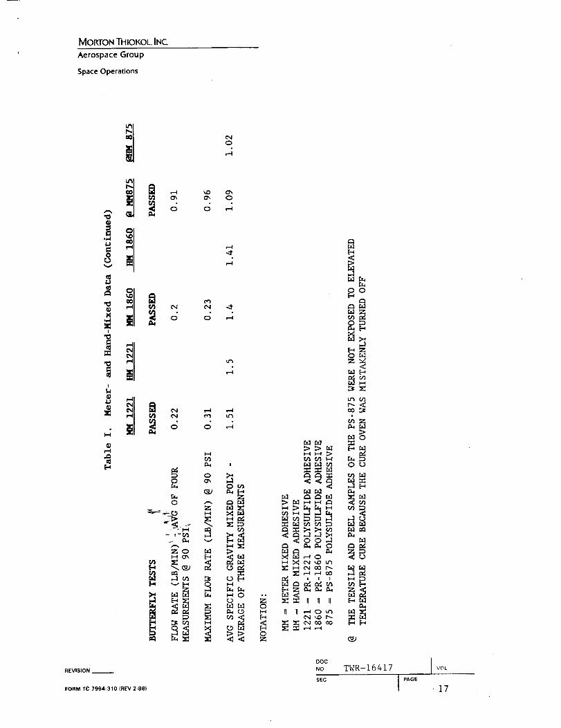
unmixed material. (These data are tabulated in Table I.) It is
important to note that these data are useful only for comparing
the static and batch mixing methods. Because these samples were
disturbed and exposed to temperature extremes during transport
from the LCC lab to the plant, it is scientifically unsound to
compare these data to the existing database. Also, the existing
database (tensile adhesion and peel) is based upon specimens which
were_pxepared from a I0:i base-to-catalyst weight ratio. As is
explainS_ in the next paragraph, the samples of these tests wereprepared- from a different component weight ratio for each
adhesive.
REVISION
FORM TC 7994-310 (REV 2-881
DOC TWR-16417 JNO VOL
SEC J PA_E i
MORTONTHIOKOL INC.
Aerospace Group
Space Operations
The meter mixer system was also checked out for its metering
accuracy and consistency. This checkout was accomplished simply
by taking weight ratio measurements. Ideally, one stroke of each
pump should volumetrically meter ten parts by weight of base to
one part of catalyst. However, weight ratios of 9.45:1, 8.94:1,
and 12.53:1 for PR-1221, PR-1860, and PS-875, respectively, were
measured at the pump exits. These ratios were repeated on each
measurement.
The metering consistency of the pumps verifies that the discrepant
ratios were not caused by a pump design defect. The differing
weight ratios could be due to one or both of the following
reasons:
o Variation in component specific gravity
O Incorrect volumetric ratios given by PRC to which the
metering pumps were sized
This issue will be resolved by further testing as outlined in
ETP-0493.
In general, the meter mixer performed adequately with minor
exceptions. The maximum flow rates at maximum pump pressure of
PR-1221 and PR-1860 were measured to be 0.31 and 0.23 pounds per
minute which are lower than the vendor guaranteed 0.5 pounds per
minute. Obviously, lower flow rates mean more time required to
apply the adhesive. However, this increase in application time
is not significant. Also, the higher pump pressure (90 psi)
caused mlcro-balloon breakage in the PS-875 base material. This
problem is not of concern since the base metering pump can be
modified to eliminate breakage. Otherwise, upon resolution of the
discrepant weight ratio problem, the metering, mixing, and
dispensing system is satisfactory for production qualification
testing.
2.0 TEST OBJECTIVE
To evaluate whether a metered mixing system can mix PR-1221
pol_-__fide adhesive as well as or better than batch-mlxed
adhesi_e_c - Also, to evaluate the quality of meter-mixed PR-1860
and PS_875 polysulfide adhesives. These adhesives are candidate
replacements for PR-1221 which will not be manufactured in the
future. The following material properties were evaluated:
o Peel strength
o Specific gravity and adhesive components of mixed adhesives
REVISION
FORM TC 7994-310 (REV 2-88)
ooc T_.- 16417 I
NO. J VOL
SEC I PAGE 2
MORTON THIOKOL INC.
Aerospace Group
SpaceOperations
0
o
Shore A hardness
o Tensile adhesion strength
o Flow rate
Finally, a visual test called the "butterfly test" was performed
to observe for bubbles and unmixed adhesive.
CONCLUSIONS
i. The present polysulfide (PR-1221) adhesive batch mixing and
application method results in unmixed and aerated material.
2. A metering, mixing, and dispensing system is advantageous to
the polysulfide mixing and application process because it:
o Can be located at the application site
o Reduces material wastes
o Allows more time for application
o Dispenses adhesive directly on the part
o Yields an air-free material
o Completely mixes the adhesive
In terms of tensile adhesion and peel strength, Shore A
hardness, and mixed material specific gravity, there is no
difference between statically-mlxed and the control (hand)-
mixed PR-1221, PR-1860, and PS-875 polysulfide adhesives.
Also, it can be said with 99 percent confidence that the
difference in average tensile adhesion and maximum peel
strengths of statically- and hand-mixed PR-1221, PR-1860, and
PS-875 adhesives is not statistically significant.
4. _ Butterfly tests showed no striations of unmixed adhesive
"a_ter statically mixing these adhesives through a series oftwo__-I/2-in, and one 3/4-in. static mixers (48 elements
to_tal).
3.0
REVISION --
FORM TC 7994-310 IREV 2-88)
DOC '13_- 16417 INO I VOL
SEC I PAGE 3
I
, ,
MORTONTHIOKOL. INC
Aerospace Group
Space Operations
5. The meter mixing system produced maximum flow rates of 0.31,
0.23, and 0.96 pounds per minute for the PR-1221, PR-1860,
and PS-875, respectively. At these flow rates, it would take
about 35, 48, and ii minutes to apply the approximate amount
of adhesive (Ii pounds) necessary for the nozzle-to-case
joint. Two of these flow rates are low compared to the 0.50
pounds per minute promised by the vendor in the purchase
contract. However, flow rate is not a critical criterion of
the polysulfide application.
. The average (three measurements) base-to-catalyst weight
ratios of PR-1221, PR-1860, and PS-875 were 9.41:1, 8.94:1,
and 12.53:1, respectively. These ratios (measured at the
sampling ports just downstream from the pumps) are discrepant
to the vendor-recommended I0:I ratio. The cause of the
differing ratios is due to incorrect base/catalyst volumetric
ratio supplied by PRC to LCC and/or lot-to-lot variations in
the specific gravities of the base and catalyst components.
7 . Specific gravities of most components of these adhesives
measured at LCC were significantly different from the values
provided by PRC.
. Repeating weight ratios of all three adhesives verify that
the metering pumps consistently meter the same volume of
components after each stroke. Also, this repeatability was
verified at the end of the 25oft hoses.
. A pump pressure of 90 psi caused significant breakage of the
micro-balloons in the PS-875 base material. The specific
gravity of the base increased by 20 percent after being
pumped.
I0. The following modifications and repairs of the metering,
mixing, and dispensing system are necessary before shipment:
o Faulty valve replacement in the control panel
o Base recycle system
o'_ - Catalyst recycle system for
_-capability
catalyst side drainage
o Clean and repaint equipment
REVISION
FORM TC 7994-310 (REV 2-88)
DOC
NO.
SEC
TWR-16417 I voL
I PAGE 4
MORTON THIOKOL INC.
Aerospace Group
Space Operations
4.0 RECOMMENDATIONS
It is recommended that:
i. Tests be performed to determine the effect of varying the
weight ratio of PR-1221, PR-1860, and PS-875 on the
characteristics of the adhesives. Also, tests be conducted
to check for any variation in the properties of each
adhesive on a lot-to-lot basis. These tests should include
tensile adhesion strength, T-peel, viscosity versus time,
Shore A hardness, and specific gravities of the componentsand the mixed adhesives.
. Pending positive outcome of the PR-1221 phase of
Recommendation No. I, the meter-mlxing system be shipped to
plant for further full-scale (NJAD) testing. However, the
previously identified improvements and repairs (Conclusion
i0) must be made prior to shipment.
5.0 DISCUSSION
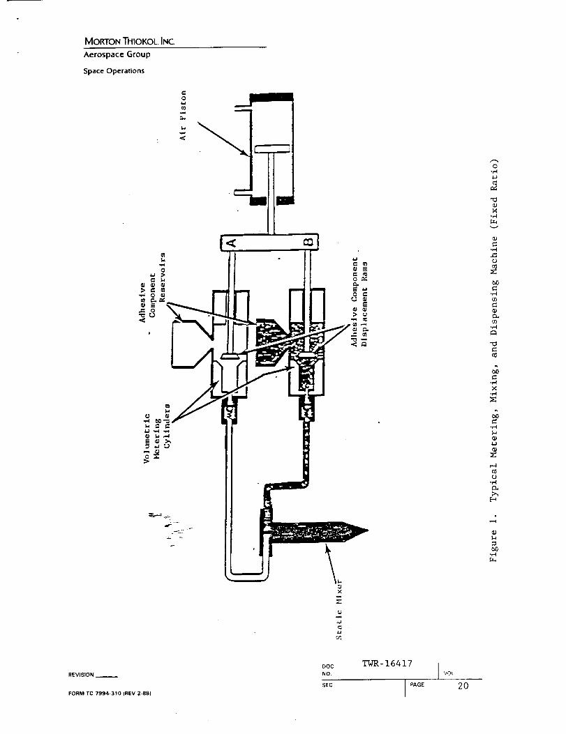
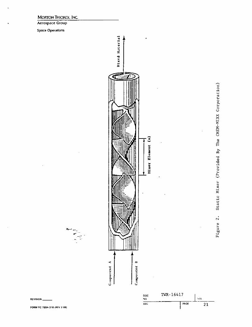
A fixed-ratio airless metering, mixing, and dispensing system is
recommended to efficiently mix polysulfide adhesives. Basically,
the recommended system consists of automatic proportioning pumps
which meter the base and catalyst flow according to the desired
base-to-catalyst weight ratio. (Figure i illustrates the basic
design of a fixed-ratio metering, mixing, and dispensing system.)
The adhesive components are mixed just prior to being dispensed
through the nozzle in a static mixer (Figure 2). A static mixer
divides and combines materials by two raised to the nth power; n
being the number of elements in the mixing chamber.
The mixed adhesive can be directly dispensed in Semco tubes or
onto the part by a gun. This metered mixing system has the
following advantages:
o A portable system, located in the facility where the
application is performed, would eliminate the need to
_-t_ansport the polysulfide adhesive from one facility toa_o_ther.
o A _reduction (about 45 percent) in the amount of adhesive
material wasted during the operation could be realized.
O Mixing the adhesive in the mixing chamber of the system
eliminates concerns that the pot life would be exceeded
before the adhesive can be applied. Pot life constraints
sometimes result in hasty and sloppy work.
REVISION
FORM TC 7994-310 (REV 2-88)
ooc TWR- 16417 INO. I VOL
SEC I PAGE 5
I
MORTON THIOIC,OL. INC.
Aerospace Group
Space Operations
The mixed material would be delivered to the part air-free as
long as the raw materials are packaged air-free.
There would be no unmixed base or catalyst; hence, adhesive
with optimum material properties would be delivered to the
part.
The following list helps to more specifically describe the model
built for polysulfide application:
(i) The catalyst is gravity fed from the component reservoir to
the pump cylinder.
(2) Because of its high viscosity, the base is fed from the
component reservoir to the pump cylinder by pressure applied
to a follower plate.
(3) Catalyst and base sampling ports are supplied for weight
ratio checks immediately after metering and for pump phasing.
(4) Prior to mixing, the components flow separately through 25feet of stainless steel braided, Teflon-lined, lightweight
hose.
(5) Initial mixing is accomplished by two _-in. by 12-element
stainless steel static mixers (24 elements total). The
catalyst is introduced into the mixer downstream from the
base. This sequence prevents catalyst from being lost on the
mixer interior because of the high volume base flow.
(6) Approximately the last three feet of hose are flexible hose
for ease of application.
(7) Attached to the hand-held dispensing gun is a 3/8-in. to
3/4-in. by 24-element disposable static mixer which was added
when it was discovered that 24 elements did not completely
mix the components.
(8) _p_n completion of the operation, the catalyst can easily berecycled to its reservoir while the system is purged of mixed
ma_e-f_fal by the base.
(9) The system has two dispensing modes; continuous and single
shot/stroke.
(i0) The catalyst reservoir tank is supplied with an agitator to
blend materials which may settle out after periods of
inactivity.
REVISION
FORM TC 7994-310 (REV 2-88}
ooc TWR- 16417 INO. _Ot
sEc I PAGE 6I
MORTON THIOKOL INC
Aerospace Group
Space Operations
(II) Both component pumps are single acting. A single acting pump
discharges material on the down stroke and reloads material
on the up stroke. To prevent cavitation, which is a problem
when pumping material of high viscosity, the pressure-applied
follower plate was added to the base reservoir. Also,
cavitation will be prevented by keeping the component
reservoirs full and the component feed lines unrestricted.
In addition, Liquid Control agreed to make the following
modiflcatlons/improvements to the machine before delivery:
o Replace a faulty valve in the control panel.
Provide a base recycle system to minimize base material
waste while the system is being charged with catalyst.
O Provide capability to completely drain the catalyst side
by pumping unused catalyst into the reservoir tank.
This option eliminates the possibility of using
unagitated catalyst after periods of inactivity.
o Clean and repaint the equipment.
The specific gravity, flow rate, peel strength, tensile
adhesion, Shore A hardness, and butterfly tests were
performed as outlined in the Test Implementation section. In
addition to these tests, base-to-catalyst weight ratios and
base and catalyst specific gravities were measured. As
instructed by the test plan (ETP-0406), tack-free time tests
were performed; however, the results are invalid since the
samples were exposed to a low temperature (about 55°F)
overnight. This type of prolonged exposure significantly
overextended the tack-free time. Specific gravities of the
components and mixed adhesives were conducted with a
pycnometer which differs from the method specified in the
test plan. However, use of a pycnometer is adequate for
these tests. Shore A hardness measurements were taken at 8,
18, and 23 days. All other tests were conducted as
originally outlined In the test plan wlth the exception of
_he adhesive cure cycles which reflect the fact that samples
w_e_ +transported from the LCC lab (Canton, Ohio) to the
Mo_Dn Thiokol lab. Weight ratio tests were performed by a
simple procedure which is:
(a) Tare out two sample cups.
(b) Engage the metering pumps for a single stroke.
(c) Allow the components to fill the tared cups at the
sampling ports.
REVISION __
FORM TC 7994-310 (REV 2-88)
Doc TWR-16417 !
NO. l _+OL
SEC PAGE 7
MORTON THIOKOL INC.
Aerospace Group
SpaceOperations
(d) Weigh the filled cups.
(e) Calculate the weight ratio by dividing the weight of the
catalyst into the weight of the base.
(f) Repeat Steps I through 5 until three data points are
obtained.
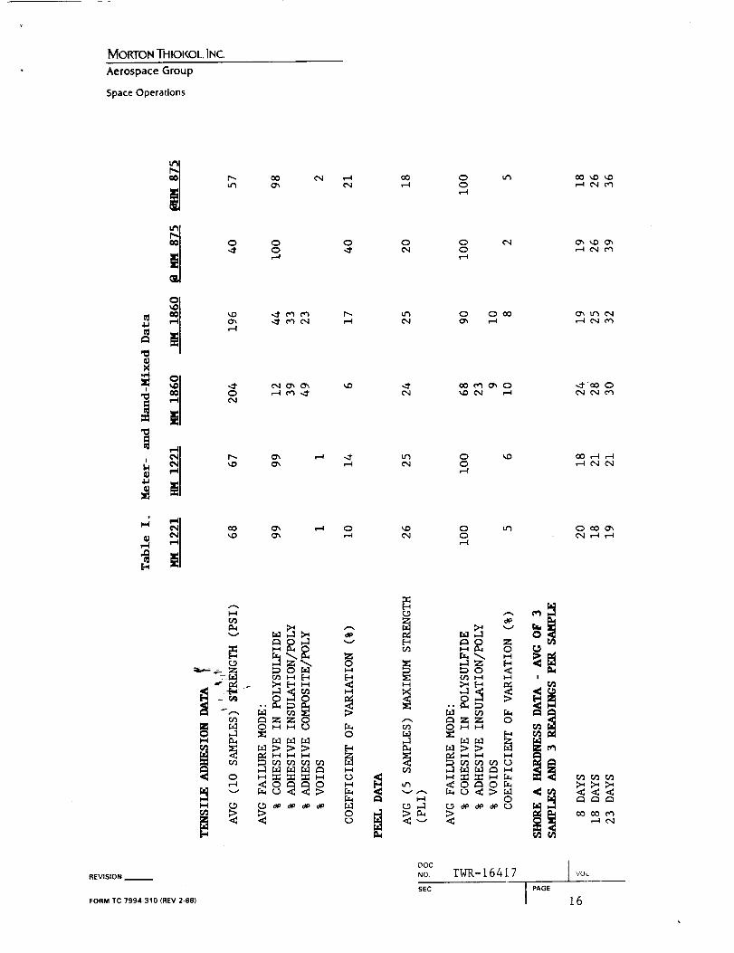
All data are tabulated in Tables I and II. The tensile
adhesion data show little difference between tensile adhesion
strengths of hand-mixed and meter-mlxed PR-1221, PR-1860, and
PS-875. Test of the null hypothesis (student distribution t
test) confirms that with 99 percent confidence, the
difference between the average tensile adhesion strengths of
each adhesive mixed by the different methods is not
statistically significant. The overall failure modes of each
meter-mixed and hand-mlxed adhesive are similar. The high
coefficients of variation are due to the erratic cure cycles
experienced by the specimens. Particularly, the PS-875
samples which were never exposed to an elevated temperature
cure (the oven at the LCC lab was mistakenly turned off).
The adhesive was tacky to the touch even after the specimens
were tested. Most PR-1221, PR-1860, and PS-875 specimens
were not allowed enough time to cure. Nevertheless, the
tensile adhesion data clearly show that static mixing is Just
as efficient as hand mixing.
The peel data reflect the same conclusion about static and
hand mixing as the tensile adhesion data. Again, statistical
analysis verifies that with 99 percent confidence, the
differences in average maximum peel strengths is not
statistically significant. Of some concern is the adhesive
failure displayed by the PR-1860 meter mixed samples (23
percent). Because the peel strength is high and there were
considerable voids, this high degree of undesirable failure
is probably due to the method of preparation of the peel
specimen.
It is important to emphasize that the data compare mixing
=_hods (static and hand) only. Comparison of the meter
m_ing data with an existing database would be unscientific,because these samples were cured at different conditions,
fo@mulated by different weight ratios, and physically
disturbed during transfer from lab to lab.
REVISION __
FORM TC 7994-310 (REV 2-88)
DOC TWR- 16417 tNO. | VOL
s_c IPAoE 8
MORTON THIOF,OL INC
Aerospace Group
SpaceOperations
Also of importance is the difference between hand and machine
batch mixing. Although hand mixing is a batch mixing method,
it is only somewhat representative of the present production
batch mixing process in the Ross mixer simply because smallamounts of adhesive are hand mixed. This distinction means
that hand-mixed batches are easier and more thoroughly mixed
than a machine-mixed adhesive. By visual observation, these
control mixes were completely mixed. Theoretically, the
control sample data reflect the optimum adhesive properties
relative to the cure cycle used in testing. This issue is
relevant because it further validates static mixing in that
the mechanical properties of the statically mixed sample are
equivalent to the controls. Hence, static mixing yields an
adhesive of excellent mechanical properties. Furthermore, a
premise for conversion from batch mixing to static mixing was
the incomplete mixing common to mixing polysulfides in a Ross
mixer. Static mixing satisfies this premise.
All other data listed in Table I (i.e., butterfly tests, and
specific gravities of the mixed adhesive) support the
conclusion that static mixing produces polysulfide adhesive
equivalent to the control mixed adhesive. The butterfly test
is a visual method for checking the mix for evidence of
unmixed material. The initial sequence of static mixers
included two 12-element mixers. Butterfly tests showed
striations of catalyst in the base after mixing with this
configuration. To improve the mix, a 24-element mixer was
added prior to the dispensing gun and each subsequent
butterfly test passed.
Table I lists the average of four and maximum flow ratemeasurements for each adhesive. The vendor was contracted to
build a machine which generates a minimum flow rates of 0.5
pounds per minute. Even at the highest pump pressure (90
psi), the maximum flow rates for PR-1221 and PR-1860 were
low. At these flow rates, the actual time for application of
the adhesives to the part will be 35, 48, and II minutes for
the PR-1221, PR-1860, and PS-875, respectively. (Each
production application averages ii poun4s of PR-1221.)
=_l_rg_sent processing time for application of adhesive to a parti__20-to 25 minutes. The low PR-1221 flow rate is not of
co__c_rn since processing time is increased by only I0 to 15
minutes. However, it is of significance when applying the
PR-1860 and modifications to the system may be necessary.
REVISION
FORM TC 7994-310 (REV 2-881
DOC T_R -16417 ]NO ','OL
SEC J PAGE 9
MORTON THIOI<OL INC_
Aerospace Group
Space Operations
Tests were conducted to check out the metering efficiency of
the meter mixing system. (The discussion in the following
paragraphs details the sequence of events as these tests were
performed on PR-1221. However, this discussion is relevant
to all three adhesives.) The base to catalyst weight ratio
out of the sampling ports repeatedly measured 9.41:1
(measured three times) and the vendor, Products Research and
Chemical Corporation (PRC), recommended ratio is i0:i. The
metering ratio was also checked at the end of the 25-ft hoses
and consistently measured to be 9.45:1. The repeating ratios
verified that once phased (stroking at the same time), the
metering pumps were consistently metering the same volume of
components. However, the 9.4:1 and i0:i ratio discrepancy is
cause for concern. Since the pumps were accurately metering,
the cause of the discrepant ratios is due to incorrect
base/catalyst volumetric ratio given by PRC and/or lot-to-lot
variations in the specific gravities of the components.
Theoretically, the metering cylinders of the pumps can be
volumetrically sized to achieve the proper weight ratio
according to the formula:
SGB
V-Wx ---
SGA
Where: V - Volumetric ratio of base to catalyst
W = Weight ratio of base to catalyst
SGB - Specific gravity of the catalyst
SGA - Specific gravity of the base
Obviously, if the components' specific gravities vary from
lot-to-lot; then, the volumetric ratio must vary to maintain
a constant weight ratio. It is not possible to vary the
volumetric ratio since the metering system is fixed ratio and
a fixed ratio machine is preferred over a variable ratio.
Therefore, the weight ratio will vary with specific
gravities. According to the polysulfide adhesive
specification (STW4-3311), the base-to-catalyst weight ratio
_a vary from 8.9:1 to 11.3:1; hence, the measured meter
m_xer-weight ratios were within specification limits.
REVISION
FORM TC 7994-310 (REV 2-88l
DOC TWR-16417 JNO. VOL
sEc j PAGE I0
MORTON THIOKOL INC
Aerospace Group
SpaceOperations
To investigate the issue further, the specific gravities of
the base and catalyst were measured to be 1.4 and 3.2,
respectively. The PRC-provided literature values are 1.4
(base) and 2.65 (catalyst). When contacted, PRC said that
polysulfide component specific gravities can vary from
batch-to-batch; particularly, the catalyst which contains
lead which frequently settles out. The tested catalyst
(specific gravity 3.2) had not been agitated prior to
testing.
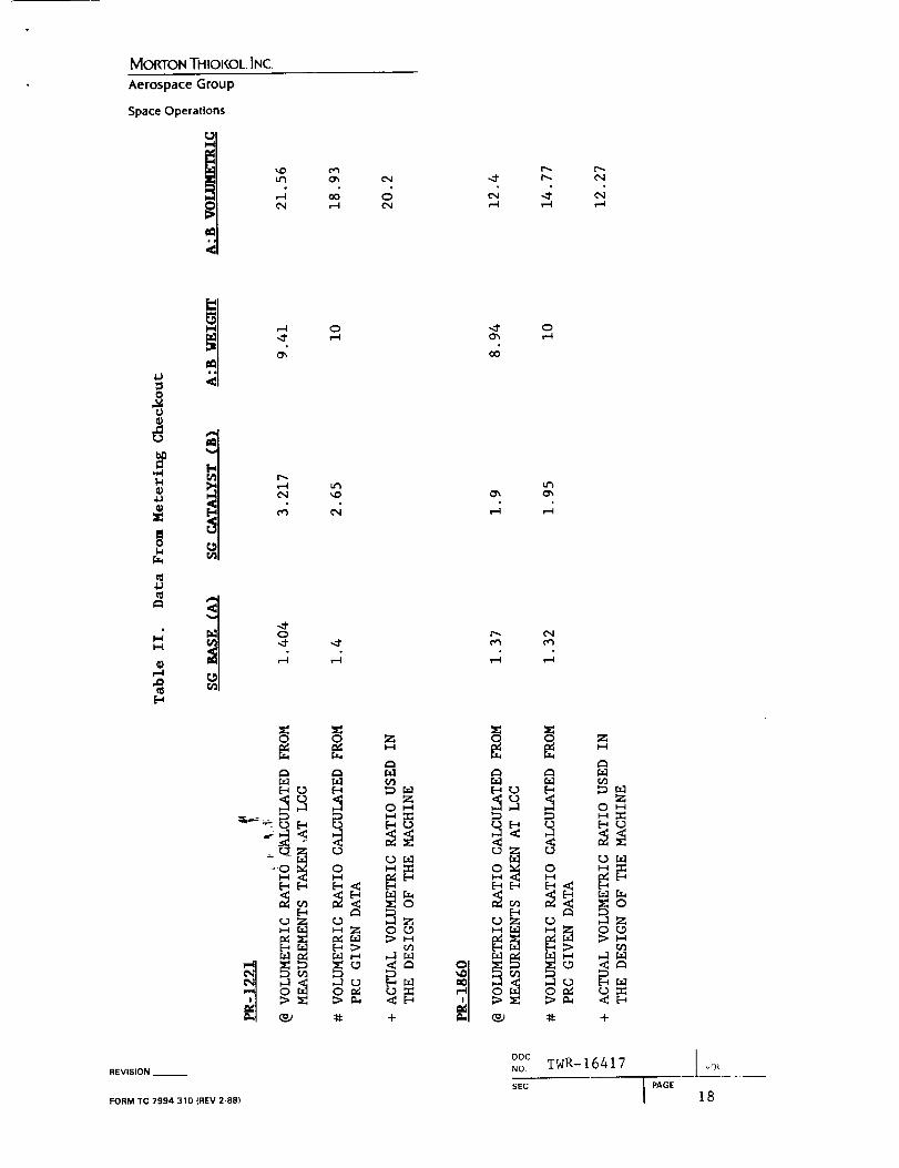
The PR-1221 metering cylinders were sized and built by LCC
based upon the volumetric ratio given by PRC (20.20:1).
However, when the vendor-specified specific gravities (1.4
and 2.65) and weight ratio (I0:i) are plugged into the above
formula, the volumetric ratio is 18.93:1. Finally, when the
measured specific gravities (1.404 and 3.217) and weight
ratio (9.41:1) are used, the volumetric ratio is 21.56:1.
Thls confusion for all three adhesives is summarized in Table
II.
The bottom line questions that must be answered by future
testing to clear the confusion are:
. Did PRC provide incorrect volumetric ratios and base and
catalyst specific gravities?
. Is there a wide lot-to-lot variation in specific
gravities of the individual components?
If Number I is determined to be the cause; then, the problem
can be resolved by adjusting the meter mixer to the new
volumetric ratio. However, if Number 2 is the problem; then,
it must be determined if an acceptable mix can be
consistently produced over the entire specific gravity
tolerance band. These tests will be performed as outlined inETP-0493.
The final item that this TWR needs to document is a problem
that may be encountered if PS-875 is used as the nozzle-to-
c_Be Joint adhesive. The PS-875 base is filled with micro-
baliJ26ns. Micro-balloons burst when under high pressures.
Of_course, this bursting effect may diminish the mechanical
properties of the adhesive.
REVISION __
FORM TC 7994-310 (REV 2-88)
ooc TWR- 16417 INO, j VOt
SEC IPAGE ii
MORTON THIOKOL INC.
Aerospace Group
Space Operations
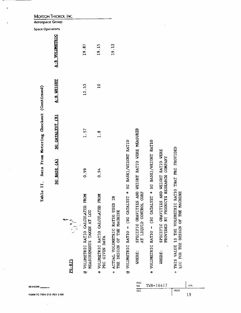
Therefore, the specific gravity of the base before and after
it was pumped was checked. A significant increase in the
specific gravity of the pumped material would indicatebreakdown of the micro-balloons. The increase when the pump
pressure was 40 psi was not significant (four percent) as the
specific gravity went from 0.99 to 1.029. However, when the
pump pressure was increased to 90 psi, the specific gravity
of the base increased by 20 percent from 0.99 to 1.18. (The
popping of the micro-balloons could actually be heard.)
Therefore, if PS-875 is chosen as a replacement, it will not
be possible to pump the base material at higher pressures
unless special modifications are made to the pump.
To summarize, pending the outcome of the tests conducted
through ETP-0493, this metering, mixing, and dispensing
system should be shipped to the plant for large-scale
qualification tests (NJAD).
6.0 TEST IMPLEMENTATION
The following test procedures were implemented for batch-mixed and
continuous-metered mixed adhesive. Also, the tests were repeated
for all three adhesives. Specimens were prepared at the meter
mixer manufacturer's facility and transported back to MTI for
testing. Control specimens were prepared at the manufacturers
facility by hand mixing an adhesive batch for each adhesive.
6.1 SDeciflc Gravity
Specific gravities on the adhesive components and mixed
adhesive (uncured) of all three adhesives were performed by a
pycnometer. Three specific gravity measurements were takenon all materials.
6.2 Flow Rate Tests
a, Tare at least three containers in which adhesive can be
dispensed.
b._-=_ispense adhesive into a tared container for at least 30
_e.conds.
c. Repeat for the other two tared containers.
d. Weigh the adhesive in the three containers.
REVISION
FORM TC 7994-310 IREV 2-88)
0oc TWR-16A17 INO. VOL
sEc I ;;AGE 12
MORTON THiOKOL. INC
Aerospace Group
SpaceOperations
e. Calculate flow rates as follows:
W
Flow Rate - -
T
Where W - Weight of the adhesive to each container
(final weight - tare weight)
T - Time in minutes the adhesive was
dispensed.
f. Record the average, maximum, and minimum flow rates.
6.3 Tack-Fre_ Time
a. Mix adhesive.
b° Apply the mixed adhesive to a Plexlglas plate, or other
suitable flat surface, to form six specimens measuring
approximately two inches in diameter by I/8-in. thick.
C. At the end of 24 hours, measured from the beginning of
the mixing period, place a polyethylene film,
approximately l-ln. wide by 6-in. long by 0.004±0.002-
in. thick, on each of the specimens.
d. Hold the film in place with a pressure of at least two
ounces per square inch of adhesive specimen for at leasttwo minutes.
e. Remove the film slowly at a right angle to the surfaceof the specimens.
f. Inspect to determine if the film has come away clean andfree of adhesive.
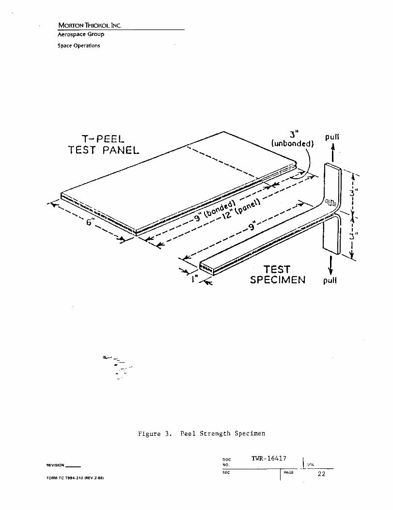
6.4 Peel Strength Test_
_+ Prepare two T-peel test panels having a minimum of five
_r-c specimens per panel as detailed in ASTM-D-1876 and use-0.300-1n. thick vulcanized NBR.
b.Bond the panels with mixed adhesive by wetting bothpanel bonding surfaces.
C. Apply an adhesive layer of approximately i/8-in, on each
bonding surface. (See Figure 3 for the specimenconfiguration.)
REVISION --
FORM TC 7994-310 IREV 2-88)
ooc TWR- 16417 1NO, VOL
SEC I PAGE 13
MOIGON THIOKOL INC
Aerospace Group
Space Opera(ions
d. Cure the adhesive for 24 hours at 120°±5°F, then for 168
hours minimum at 75°±5°F.
e. Cut each panel into separate one-inch wide specimens.
f. Pull the specimens at i0 in. per minute and record the
peel strength in pounds per linear inch and the failure
mode.
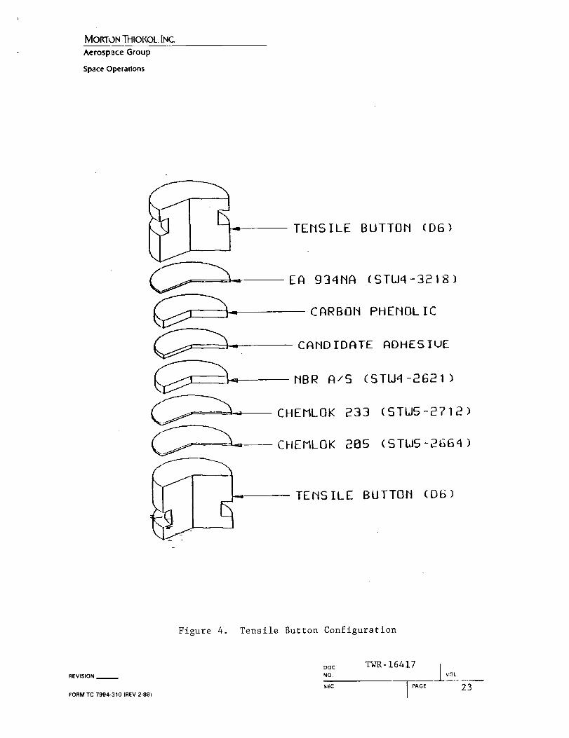
6.5 Tensile Adhesion Tests
The specimen configuration for these tests is illustrated in
Figure 4.
a. Obtain 20 D6 steel tensile adhesion buttons which have
been vapor degreased and grit blasted. Remove grit with
a nitrogen blast within four hours of bonding or
vulcanizing.
Do Apply a coat of Chemlok 205 to I0 buttons.
minutes to dry.
Allow I0
C° Apply a coat of Chemlok 233 to the same i0 buttons used
in Step 8.5 (b). Allow 30 minutes to dry.
d. Lay up 0.i0 in. of NBR (STW4-2621) on the i0 buttons
used in Step 8.5 (c).
e. Cure 90 120 minutes at 300°±I0°F and i00 psi.
f. Obtain I0 CP discs which have been cut out with the
carbon fibers parallel to the bonding surfaces.
g. TCA wlpe the CP discs. Allow 30 minutes to dry.
h. Abrade the CP discs with 180 - 220 gritmaterial.
abrasive
i. TCA wlpe the CP discs. Allow 30 minutes to dry.
j__: Bond the CP discs to i0 D6 buttons with a minimum
- bondllne of EA 934NA. Secure with shrink tape.
k. Cure for a minimum of 180 minutes at 170°F.
l° TCA wipe both the CP and NBR bonding surfaces. Allow 30
minutes to dry.
m° Abrade both the CP and NBR bonding surfaces with 180-
220 grit abrasive material.
REVISION
FORM TC 7994-310 (REV 2-88)
Doc TWR- 16417 INO I VOL
sEc I PAGE 14
MORTON THIOKOL INC.
Aerospace Group
SpaceOperations
6.6
6.7
n. TCA wipe both the CP and NBR bonding surfaces. Allow 30
minutes to dry.
o. Bond I0 D6/CP buttons to i0 D6/NBR buttons with a
O.060-in. bondline for mixed adhesive. Secure with
shrink tape.
p. Cure for 24 hours at 120°±5°F, then for 168 hours
minimum at 75°±5°F.
q. Condition Set B at 75°±5°F for two hours minimum before
pulling. The crosshead rate shall be 0.5 in./min.
r. Record the tensile adhesion strength and failure mode of
each specimen. Also, examine for voids and note otheranomalies.
Shore A Hardness Tests
a. Pour mixed adhesive into five aluminum weighing dishes.
b. Cure the adhesive for 24 hours at 120°±5°F, then for 168hours minimum at 75°±5°F.
c. Measure Shore A hardness upon completion of the cure
cycle.
d. Measure Shore A hardness three days after cure.
e. Measure Shore A hardness eight days after cure.
f. Measure Shore A hardness 13 days after cure.
g. Measure Shore A hardness 18 days after cure.
h. Measure Shore A hardness 23 days after cure.
"Butterfly" Tests
_a__ Fold a heavy 12- by 12-in. piece of kraft paper in half
be -Apply a bead of adhesive in the crease of the kraft
paper.
c. Fold the kraft paper in several layers so that theadhesive is sandwiched.
d. Thoroughly smear the adhesive.
e. Unfold the kraft paper and observe for unmixed adhesive.
REVISION __
FORM TC 7994-310 (REV 2-88)
DOC TWR- 16417 INO. VOL
SEC I PAGE 15
I
MORTON THIOKOL INC.
Aerospace Group
Space Operations
I
v-I
r_ o0ur_ c:h
0 0-_" 0
r-I
_D o_
oo 0% i--I_D 0%
00 0
O O O
_ O 000
i--I
O0 _O _Or--I C'_I ('_
O_ _0 C:hr-a ¢_1 c,'_
O'_ u_ c'q
-.1"'O00
0000',
¢[1 r.el 0,'1
REVISION
FORM TC 7994-310 (REV 2-88)
DOCNO TWR-16417
SEC
J VOL
MORTON THIOKOL INC.
Aerospace Group
Space Operations
c"qO
v
_ `5
o'_ O
,S ,-,
-,1"
o'3eq -,,1'
u'-'l
i--I
I,.-,ItJ3
O_rJ3
_.-_0 _, [._ r.t.lr.=.l
vE-_ i-i,-..1 _
REVISION
FORM TC 7994-310 (REV 2-88|
r._;>H
r._
¢./3 1_r._=_
N U ,-_
u_r_
O 0E_
_ZoM
_m
!
M m O
,", r._ _ r.=.l
_o_ __D u_
II II _
DOC
NO TWR-16417
SEC
t VOL
I PAGE 17
MOKI"OI_THIOKOLINC.
Aerospace Group
Space Operations
_ou-_
(N
owl
T-Ic;
.4" I_ c.4
,--4 _
(9
+1,,,4
J,J
¢.1
°i-I
(9i-4
v-I
p_i--I
...t"o.d-
o
REVISION__
FORM TC 7994-310 (REV2-88)
U'3
"4'
r._ r._
_[-" <_!++-0 0I-I I-4
F.
l.-I
r_ r._
0
Z
H
[.3
.4
o
u_
,4
o.,i
o_ o_ z
O_ ,-1 O_
_.o _ _ _o
i ++ _J _ +
DOCNO. TWR-16_17
SEC
l vOL
IPAGE t8
MORTON THIOKOL INC.
Aerospace Group
Space Operations
<
oou-1
a_
v
S0
m
rJ3
0%
oi-q
oo
o%
•.r- " O_Z O
-- 0 0
0 Z 0
_ [-4
:1 0 O_
o _ oI-4
(3 L_ _ 0
m _ m _ m
-_ _ -3< _ __oz _ o _ _ _.
_ 0 _ 0 _
0
Z 0 Co M
_ o _+ _J ¢t: +
Zt-I:z:0
0
Z0
0
oo
REVISION__
FORM TC 7994-310 (REV2-88)
DOCNO
SEC
TWR-16417
J PAGE
J VOL
19
MORTON THIOKOL INC.
Aerospace Group
Space Operations
O
REVISION
FORM TC 7994-310 IREV _Z-88)
x
DOC
NOr
SEC
E
0_..
0
7Z
TWR- 16417
rot
#
J=_J
m
m
N
2
[--t
,--4
=
I PAGE 20
MORTON THIOKOL INC
Aerospace Group
Space Operations
Ill'-_.--_-
|
l'd
X
CO
0
0U
XX
I
U
"O.r-I
O
v
.,N
U._-I4J
4--IU3
--I
REVISION __
FORM TC 7994-310 (REV 2-881
<
=
=
.D
_.='3
DOC
NO
TWR-16417
SECI PAGE
I '_OL
21
MORTON THIOKOL INC.
Aerospace Group
Space Operations
T-PEEL 'unb y-'on "" pull
TEST PAI_EL _'<--.... _aei' t
I_....,... ..4./ /.,..,," . ..._ J I...+ LII,
"_" TEST "_"_.._TEST F'
I_ SPECIMEH null
Figure 3. Peel Strength Specimen
REVISION I
FORM TC 7994-310 (REV 2-88)
OOC
NO.
SEC
TWR-16417
I '40L
I PAGE 22
MORTON THIOKOL INC
Aerospace Group
Space Operations
TEMSILE BUTTOM (D6)
EA g34MA (STLI4-321B
_ CHEMLOK
_--- CHEMLOK
I" TEMSILE
CARBOM PHEMOLIC
CAMDIDATE ADHESIUE
MBR A/S (STU_-2621)
233 (STUS-2?I 2 )
285 (STW5-2664)
BUTTOM (DIS)
Figure 4. Tensile Button Configuration
REVISION I
FORM TC 7994-310 IREV 2 8B)
Noa°C TWR-16417 I voLSEC
I PAGE23