Embed Size (px)
Citation preview
Journal of Engineering Science and Technology Review 6 (2) (2013) 115-119
Research Article
Model Predictive Control on Constant Voltage Output of a Proton Exchange Membrane Fuel Cell
Liping Fan1,*, Jun Zhang2 and Chong Li2
1College of Environment and Safety Engineering, Shenyang University of Chemical Technology, Shenyang, 110142- China
2College of Information Engineering, Shenyang University of Chemical Technology, Shenyang 110142- China
Received 15 May 2013; Accepted 25 July 2013 ___________________________________________________________________________________________ Abstract
As one of the promising renewable energy sources, the proton exchange membrane fuel cell (PEMFC) has received more and more attentions in recent years. Performance improvement is necessary for popularization and application of PEMFC. A model predictive controller based on the receding horizon control approach is designed for the PEMFC. Hydrogen pressure and oxygen pressure are chosen as the control variables respectively, and the main control objective is to keep the output voltage constant. Simulation results show that the designed MPC controller can give a satisfactory control effect.
Keywords: PEMFC, receding horizon control, model predictive controller, simulation __________________________________________________________________________________________ 1. Introduction With the increasingly serious energy crisis and deteriorating environmental conditions, new energy sources with low pollution and high conversion efficiency are needed to develop. Fuel cells are promising energy sources that produce electrical currents with almost null pollutant emissions [1]. The proton exchange membrane fuel cell (PEMFC), as a kind of power generating device, has been attached importance by all governments and enterprises in the world. PEMFC can convert chemical energy in hydrogen and oxygen directly to electric energy cleanly and efficiently [2], [3]. PEMFC can be used as emergency power supply and small mobile power supply for outdoors power supply, emergency power supply and high reliable and high stable power supply [4]. On the other hand, it also can be used as the power of new generation vehicle owing to its low working temperature, quick starting speed, high power density (small volume). Besides, on the contrast of centralized power supply, PEMFC can be considered as distribution power supply and be gridded into power supply system for peak modulation [5], [6]. The performance of PEMFC, being important and getting more and more attention in recent years, is known to be influenced by many parameters such as operating temperatures both fuel cell and humidifiers, pressure, flow rates and relative humidity of fuel and oxidant gases [7]. Maintaining a fuel cell system in correct operating conditions requires good system control. Model predictive control (MPC) is an optimization strategy for the control of constrained dynamic systems [8]. MPC uses multi-step
prediction, rolling optimization and feedback correction control strategies [9], so it can not only give a good control effect and strong robustness, but also have an advantage of less demand on the accuracy of the model. It is an effective method to solve complex industrial process control [10], [11]. In this paper, a simulation platform for fuel cell was set up based on a single fuel cell model with hydrogen pressure and oxygen pressure as input variables and voltage as output variable. A model predictive controller (MPC) is designed according to the Receding Horizon Control (RHC) approach. This paper is organized as follows. The mathematical model for a typical proton exchange membrane fuel cell is described in Section 2. Section 3 presents a brief description of designing a MPC controller for PEMFC. Simulation results are presented in section 4 to confirm the effectiveness and the applicability of the proposed method. 2. Mathematical Model of PEMFC Mathematical models and simulation are needed as tools in optimization of fuel cells. In system studies, it is important to have an adequate model to estimate overall performance of a PEM fuel cell in terms of operating conditions without extensive calculations [12]. PEM fuel cell electrochemical process starts on the anode side where H2 molecules are brought by flow plate channels. Anode catalyst divides hydrogen on protons H+ that travel to cathode through membrane and electrons e- that travel to cathode over external electrical circuit. At the cathode hydrogen protons H+ and electrons e- combine with oxygen O2 by use of catalyst, to form water H2O and heat. Described reactions can be expressed by the following equations [13], [14], [15]:
______________ * E-mail address: [email protected] ISSN: 1791-2377 © 2013 Kavala Institute of Technology. All rights reserved.
Jestr JOURNAL OF Engineering Science and Technology Review
www.jestr.org
Liping Fan, Jun Zhang and Chong Li/Journal of Engineering Science and Technology Review 6 (2) (2013) 115-119
116
+ -
2H 2H +2e (Anode)→ (1)
+ -2 2
1 O +H +2e H O (Cathode)2
→
(2)
The thermodynamic potential of the cell representing its reversible voltage can be represented by the following formula
ref H2 O2
1( ) [ln( ) ln( )]2 2 2 2nernstG S RTE T T P PF F FΔ Δ
= + − + + (3)
where, ΔG is Gibbs free energy, F is Faraday constant, ΔS is Entropy change, R is Universal gas constant, PH2 and PO2 are respectively the pressure of H2 and O2, T is the ambient temperature, and Tref is the reference temperature. Empirical formula for fuel cell voltage is
conohmicactnernstfc VVVEV −−−= (4) The activation polarization voltage can be expressed as
2act 1 2 3 O 4ln( ) ln( )V T T C T iξ ξ ξ ξ= + + + (5)
where ξ1, ξ2, ξ3, ξ4 are the model coefficients of experimental data on the basis of fluid dynamics, thermal and electrochemical driving force, i is current density,
2OC is
the available oxygen concentration, and it can be expressed as
2
O2O 498
65.08 10 T
PCe−=
×
(6)
The ohmic voltage drop associated with the conduction of protons through the solid electrolyte can be described as
ohmic M C( )V i R R= + (7) where RC is the contact resistance to electron flow, and RM is the resistance to proton transfer through the membrane, which can be described as
fc
fc
2 2.5fc
M -3034.18
181.6 1 0.03 0.062303
0.634 3 e
MM
TT
lRA
Ti iA A
iA
ρ
ρ
ψ⎡ ⎤⎛ ⎞⎢ ⎜ ⎟⎥⎜ ⎟⎢ ⎥⎝ ⎠⎣ ⎦
⋅=
⎡ ⎤⎛ ⎞⎛ ⎞ ⎛ ⎞+ +⎢ ⎥⎜ ⎟ ⎜ ⎟⎜ ⎟⎝ ⎠ ⎝ ⎠⎝ ⎠⎢ ⎥⎣ ⎦=
⎡ ⎤⎛ ⎞− − ⎜ ⎟⎢ ⎥⎝ ⎠⎣ ⎦
,
(8)
where ρM is the membrane specific resistivity, l is the membrane thickness, A is the membrane active area, and ψ is a specific coefficient for every type of membrane. The voltage drop resulting from the mass transportation effects can be described by the following expression:
)1(lnmax
con iiBV −−= (9)
where B is a constant depending on the type of fuel cell, imax is the maximum electrical current. For a PEMFC, the two layer separated by the membrane act as double charged layer, which can store electrical energy, and can be treated as a super capacitor. So the dynamics of the fuel cell voltage can be modeled by the addition of a capacitor C to the steady state model [16]. The effect of double charge layer is modelled by a capacitor C connected in parallel with the activation resistance. The differential equation describes the capacitor voltage is
C C
con act
ddV Vit C R R= −
+ (10)
Then equation (4) can be modified to
fc nernst C ohmV E V V= − − (11) Based on the above described mathematical model, a Matlab/simulink simulation model of the PEMFC can be set up [17]. Parameters used in the simulation model are shown in Table 1. Table 1: Model parameters
Parameters values Parameters values
ΔG (J/mol) 237180 ξ2 -3.12×10⁻³
R(J/mol/K) 8.314 ξ3 -7.4×10⁻⁵
ΔS (mol.K) 164.025 ξ4 1.87×10⁻⁴
T(K) 353 Tref(K) 298.15
F(C/mol) 96.487 l(um) 0.0178
PH2(atm) 2 A(cm2) 50.6
PO2(atm) 1 C(F) 0.25
ξ1 0.9514
3. Controller Designing Many factors, such as temperature variations, oxygen and hydrogen pressure, load disturbance, can affect the output voltage of fuel cells. These voltage variations can be compensated by fuel pressure controlling. The control laws of MPC are based on the following ideas: In time k, the optimal solution of the performance index J is calculated, and the first element of the optimal control sequence Δu(ki) is used as the control input. In time k+1, the optimal solution of the performance index J is calculated repeatedly based on the new state, and this is also known as Receding Horizon Control [18], [19]. For a given discrete-time systems: ( 1) ( ) ( )( ) ( )m m m m
m m
x k A x k B u ky k C x k
+ = +
= (12)
The MPC state space model can be expressed as follows:
Liping Fan, Jun Zhang and Chong Li/Journal of Engineering Science and Technology Review 6 (2) (2013) 115-119
117
Δxm (k +1)y (k +1)
"
#$
%
&'
x (k +1)
=Am OT
CmAm 1
"
#
$$$
%
&
'''
A
Δxm (k )y (k )
"
#$
%
&'
x (k )
+BmCmBm
"
#$$
%
&''
B
Δu (k )
y (k ) = [Om 1]C Δxm (k )
y (k )
"
#$
%
&'
(13)
which subjects to ( ) , ( )n m
mx k X R u k U R∈ ⊂ ∈ ⊂ (14) where xm(k), u(k), y(k) are state, input and output vectors, respectively. Then the predicted expression of x and y at sampling time ki can be obtained as
2
1 2
( 1 ) ( ) ( )
( 2 ) ( ) ( ) ( 1)
( ) ( ) ( ) ( 1)
( 1)
P P P
P C
i i i i
i i i i i
N N Ni P i i i i
N Ni C
x k k Ax k B u k
x k k A x k AB u k B u k
x k N k A x k A B u k B u k
A B u k N
− −
−
+ = + Δ
+ = + Δ + Δ +
+ = + Δ + Δ +
+ + Δ + −
M
L
(15)
1
2
( ) ( ) ( )
( 1)
( 1)
P P
P
P C
N Ni P i i i
Ni
N Ni C
y k N k CA x k CA B u k
CB u k
CA B u k N
−
−
−
+ = + Δ
+ Δ + +
+ Δ + −
L (16)
If the following vectors are defined
[ ( 1 ), ( 2 ),
( 3 ), ( )]i i i i
Ti i i P i
X x k k x k k
x k k x k N k
= + +
+ +L (17)
[ ( 1 ), ( 2 ),
( 3 ), ( )]i i i i
Ti i i P i
Y y k k y k k
y k k y k N k
= + +
+ +L (18)
[ ( ), ( 1), ( 2),
( 1)] i i i
Ti C
U u k u k u ku k N
Δ = Δ Δ + Δ +
Δ + −L (19)
The output expression can be denoted as Y FX Φ U= + Δ (20) where
2 3[ ... ]NP TF CA CA CA CA=
2
1 2 3
0 0 00 0
0
P CP P P
P C
N NN N NN N
CBCAB CB
Φ CA B CAB CB
CA B CA B CA B CA B−− − −
×
⎡ ⎤⎢ ⎥⎢ ⎥⎢ ⎥=⎢ ⎥⎢ ⎥⎢ ⎥⎣ ⎦
LLL
ML
(21)
For the current state, model predictive control is to solve the optimization problem of the form
( ) ( )TS SJ R Y R Y UR U= − − +Δ Δ (22)
which subject to the following constraints:
min max
min max
min max
U U UU U uY Y Y
≤ ≤
Δ ≤ Δ ≤ Δ
≤ ≤
(23)
in which [1,1 ,1] ( )T
S iR r k= L , ( )ir k is the steady-state,
and C Cw N NR r I I= × , rw is the weight. From
0JU
∂=
∂Δ (24)
the optimal solution of control signals and performance indicators can be solved as
1( ) ( ( ))T TS iU Φ Φ R Φ R Fx k−Δ = + − (25)
min1
( ( )) ( ( ))
( ( )) ( ) ( ( ))C C
TS i S i
T T TS i w N N S i
J R Fx k R Fx kR Fx k Φ Φ Φ r I Φ R Fx k−
×
= − − −
− + −
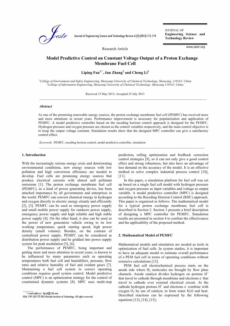
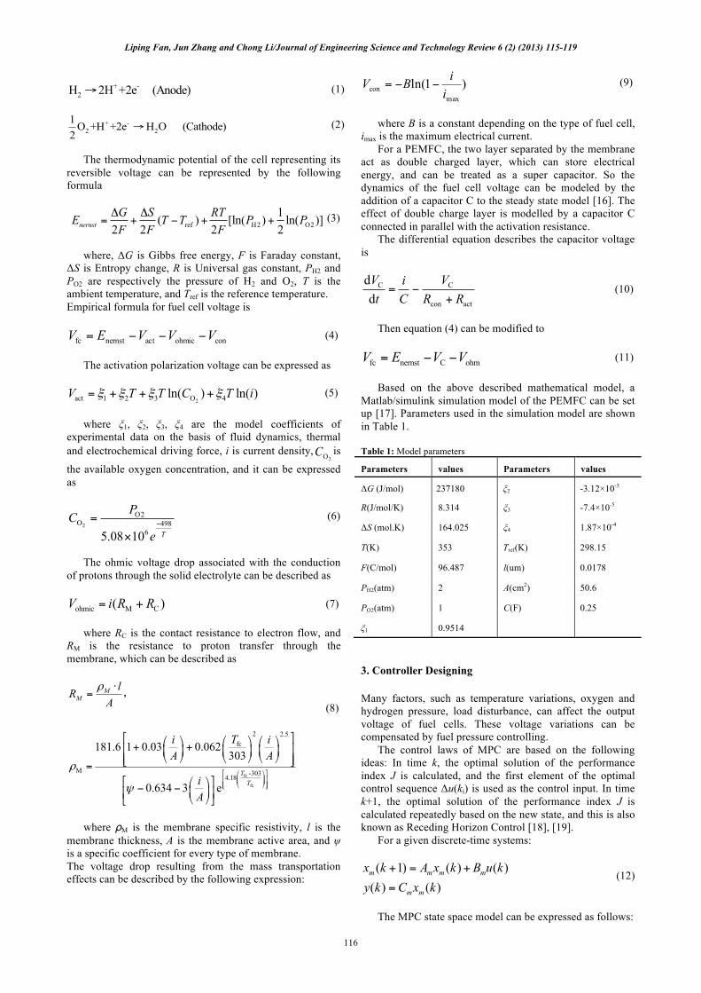
(26) 4. Simulation and Results Analysis Select the predictive region length NP=20, the control region length NC=4, rw=0.001. The output steady-state voltage is set at Vfc=1V. First PO2 is chosen as a control variable. Fig. 1 shows the simulation running curves without constraints, and Fig. 2 shows the corresponding curves with constraints. The constraint conditions are [0,10], [ 3,3]u u∈ Δ ∈ − . It can be seen from Fig. 1 and Fig. 2 that MPC can make the output voltage of the fuel cell follow the reference value quick and accurately. By comparing Fig. 1 with Fig. 2, it also can be seen that, the steady-state can be reached at 0.25s without constraints and 0.5s with constraints. When PO2 is chosen as the control variable, the fuel cell can reach the stable state rapidly and soon after output a constant voltage at the setting value.
V fc,V
t,s
Liping Fan, Jun Zhang and Chong Li/Journal of Engineering Science and Technology Review 6 (2) (2013) 115-119
118
Fig.1. Simulation Results Corresponding to PO2 as Control Variable Without Constraints
Fig. 2. Simulation Results Corresponding to PO2 as Control Variable with Constraints
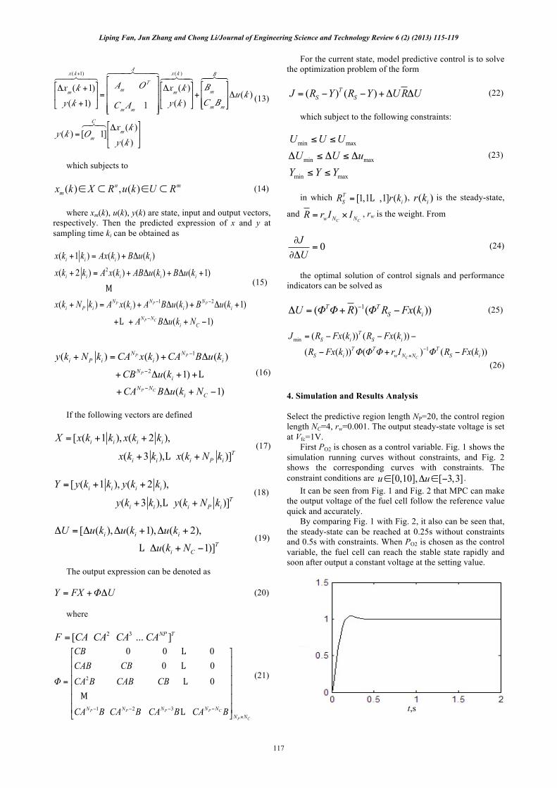
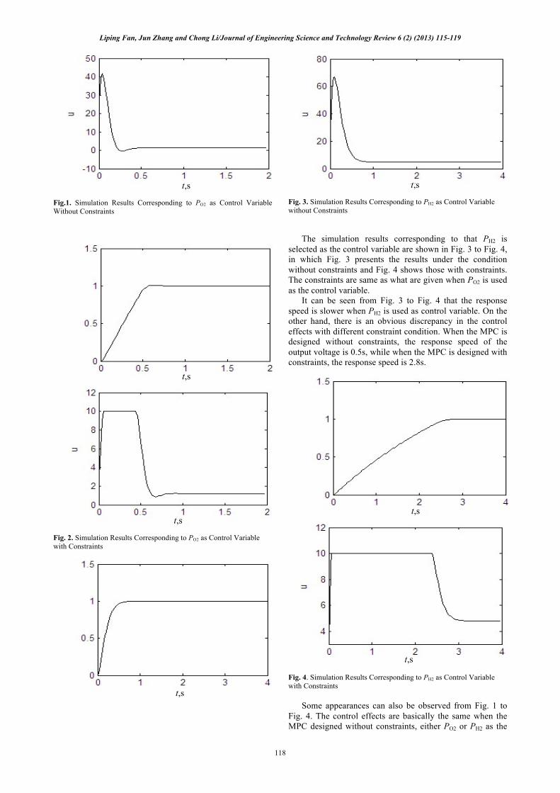
Fig. 3. Simulation Results Corresponding to PH2 as Control Variable without Constraints The simulation results corresponding to that PH2 is selected as the control variable are shown in Fig. 3 to Fig. 4, in which Fig. 3 presents the results under the condition without constraints and Fig. 4 shows those with constraints. The constraints are same as what are given when PO2 is used as the control variable. It can be seen from Fig. 3 to Fig. 4 that the response speed is slower when PH2 is used as control variable. On the other hand, there is an obvious discrepancy in the control effects with different constraint condition. When the MPC is designed without constraints, the response speed of the output voltage is 0.5s, while when the MPC is designed with constraints, the response speed is 2.8s.
Fig. 4. Simulation Results Corresponding to PH2 as Control Variable with Constraints Some appearances can also be observed from Fig. 1 to Fig. 4. The control effects are basically the same when the MPC designed without constraints, either PO2 or PH2 as the
V fc,V
t,s
t,s
V fc,V
t,s
t,s t,s
V fc,V
t,s
t,s
Liping Fan, Jun Zhang and Chong Li/Journal of Engineering Science and Technology Review 6 (2) (2013) 115-119
119
control variable. While when the constraint conditions is considered in designing MPC, the control effects of these two conditions shows obvious distinctness. Therefore, using PO2 as the control variable can get an ideal control effect, no matter whether the constraints exist. 5. Conclusion By using model predictive controller, the fuel cell can not only have fast response characteristic, but also have good steady-state behavior and strong robustness. The suitable
MPC schemes can get satisfactory results in tracking a given voltage and guarantee that the fuel cells have constant voltage outputs. Acknowledgements This work was supported by the National Key Technology Research and Development Program of China under Grant 2012BAF09B01, and the Science and Technology Research Project of Liaoning Education Department of China under Grant L2012140.
______________________________
References 1. Samosir, A. S., Sutikno, T., Yatim, A. H. M., “Dynamic evolution
control for fuel cell DC-DC converter”, TELKOMNIKA 9 (1), 2011, pp. 183-190.
2. Wee, J. H., “Applications of proton exchange membrane fuel cell systems”, Renewable and Sustainable Energy Reviews 11 (8), 2007, pp. 1720-1738.
3. Logan, B. E., “Scaling up microbial fuel cells and other bioelectrochemical systems”, Applied Microbiology and Biotechnology 85(6), 2010, pp. 1665-1671.
4. Gencoglu, M. T., Ural, Z., “Design of a PEM fuel cell system for residential application”, International Journal of Hydrogen Energy 34 (12), 2009, pp. 5242–5248.
5. Pukrushpan, J., Stefanopoulou, A., Peng, H., “Control of fuel cell breathing”, IEEE Control Systems 24 (2), 2004, pp. 30-46.
6. Kunusch, C., Puleston., P. F., Mayosky, M. A., Riera, J., “Sliding mode strategy for PEM fuel cells stacks breathing control using a super-twisting algorithm”, IEEE Transactions on Control Systems Technology 17 (1), 2009, pp. 167-174.
7. Kaytakoglu, S., Akyalm, L., “Optimization of parametric performance of a PEMFC”, International Journal of Hydrogen Energy 32 (17), 2007, pp. 4418-4423.
8. Ashoori, A., Moshiri, B., Sedigh, A. K., Bakhtiari, M. R., “Optimal control of a nonlinear fed-batch fermentation process using model predictive approach”, Journal of Process Control 19 (7), 2009, pp. 1162-1173.
9. Domınguez, L. F., Pistikopoulos, E. N., “Recent advances in explicit multiparametric nonlinear model predictive control”, Industrial & Engineering Chemistry Research 50 (2), 2011, pp. 609-619.
10. Holkar, K. S., Waghmare, L. M., “An overview of model predictive control”, International Journal of Control and Automation 3 (4), 2010, pp. 47-63.
11. Qin, S. J., Badgwell, T. A.. “A survey of industrial model predictive control technology”, Control engineering practice 11 (7), 2003, pp. 733-764.
12. Carnes, B., Djilal, N., “Systematic parameter estimation for PEM fuel cell models”, Journal of Power Sources 144 (1), 2005, pp. 83-93.
13. Moreira, M. V., Silva, G. E., “A practical model for evaluating the performance of proton exchange membrane fuel cells”, Renewable Energy 34 (7), 2009, pp. 1734-1741.
14. Rezazadeh, A., Sedighizadeh, M., Karimi, M., “Proton exchange membrane fuel cell control using a predictive control based on neural network”, International Journal of Computer and Electrical Engineering 2 (1), 2010, 81-85
15. Youssef M. E., Nadi K. E., Khalil M. H., Lumped model for proton exchange membrane fuel cell (PEMFC). International Journal of Electrochemical Science 5, 2010, pp. 267-277.
16. Esmaeili, S., Shafiee, M., “Simulation of dynamic response of small wind-photovoltaic-fuel cell hybrid energy system”, Smart Grid and Renewable Energy 3 (3), 2012, pp. 194-203.
17. Fan, L. P., “Simulation study on the influence factors of generated output of proton exchange membrane fuel cell”, Applied Mechanics and Materials 121-126, 2012, pp. 2887-2891.
18. Hedjar, R.., “Application of nonlinear rescaling method to model predictive control”, International Journal of Control, Automation, and Systems 8 (4), 2010, pp. 762-768.
19. Thammano, A., Ruxpakawong, P., “Nonlinear dynamic system identification using recurrent neural network with multi-segment piecewise-linear connection weight”, Memetic Computing 2 (4) 2010, pp. 273-282.