Embed Size (px)
Citation preview
Before driving
Introduction 2
Instrumentation 5
Controls and features 18
Seating and safety restraints 53
Starting and driving
Starting 83
Driving 91
Roadside emergencies 135
Servicing
Maintenance and care 154
Capacities and specifications 213
Reporting safety defects 220
Index 221
Contents
1
ICONSIndicates a warning. Read thefollowing section on Warnings fora full explanation of them.
Indicates that vehicle informationrelated to recycling and otherenvironmental concerns will follow.
We must all play our part inprotecting the environment.Correct vehicle usage and theauthorized disposal of wastecleaning and lubrication materialsare significant steps towards thisaim.
WARNINGSHow can you reduce the risk ofpersonal injury and preventpossible damage to others, yourvehicle and its equipment?
In this owner’s guide, answers tosuch questions are contained incomments highlighted by thewarning triangle symbol.
BREAKING-IN YOUR VEHICLEThere are no particular breaking-inrules for your vehicle. Simply avoiddriving too briskly during the first1,600 km (1,000 miles) of driving.Vary speeds frequently. This isnecessary to give the moving partsa chance to break in.
If possible, you should avoid fulluse of the brakes for the first1,600 km (1,000 miles).
From 1,600 km (1,000 miles)onwards you can gradually
com_icons.01
com_warn.01
com_breaking_vehicle.01
Introduction
2
increase the performance of yourvehicle up to the permittedmaximum speeds.
INFORMATION ABOUT THISGUIDEThe information found in thisguide was in effect at the time ofprinting. Ford may change thecontents without notice andwithout incurring obligation.
Notice to owners of utility typevehiclesBefore you drive your vehicle,please read this Owner’s Guidecarefully. Your vehicle is not apassenger car. As with othervehicles of this type, failure tooperate this vehicle correctly mayresult in loss of control or anaccident.
Be sure to read Driving off roadin the Driving chapter as well asthe “Four Wheeling” supplementincluded with 4WD and utility typevehicles.
Using your vehicle with asnowplowFor more information andguidelines for using your vehiclewith a snowplow, refer to theDriving chapter.
Using your light truck as anambulance
Do not use this vehicle asan ambulance.
com_info_guide.01
f12_utility_notice
f12_snowplowing
f12_no_ambulance
Introduction
3
Your vehicle is not equipped withthe Ford Ambulance Preparationpackage.
Introduction
4
3
50
30 7040
80
120
140
40
20
90
60
80
60 100
20 km/h
0000052 4
5
6
1
L
H
E
F
3
50
30 7040
80
120
140
40
20
90
60
80
60 100
20 km/h
0000052 4
5
6
1
L
H
E
F
P
ON
OFF
RES
SETACCEL
COAST
INT 2INT 1OFF
OVERDRIVE OFF
PANELDIM
AUTOLAMP
C
H
8
18
C
H
8
18
SRS
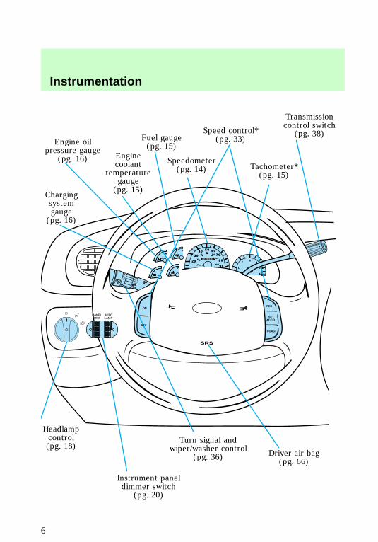
Chargingsystemgauge(pg. 16)
Engine oilpressure gauge
(pg. 16) Enginecoolant
temperaturegauge(pg. 15)
Fuel gauge(pg. 15)
Speedometer(pg. 14)
Speed control*(pg. 33)
Tachometer*(pg. 15)
Transmissioncontrol switch
(pg. 38)
Driver air bag(pg. 66)
Turn signal andwiper/washer control
(pg. 36)
Instrument paneldimmer switch
(pg. 20)
Headlampcontrol(pg. 18)
Instrumentation
6
REW1
FF2
SIDE 1-23
FM 1 ST
VOL – PUSH ON
AMFM BASS TREB BAL FADE
AUTOSET
CLK
SEEK
TUNEDISCS
SCAN
4
DOLBY SYSTEM
EJ TAPE CD
COMP5
SHUFFLE6
WARMCOOL
FLR & DEF
*MAXA/C
FLOOR
PANEL &FLOOR
DEF
OFF
PANEL
*A/C
LO
HI
PASSENGER AIRBAG
ON
OFF
OFF
2H4H
4L
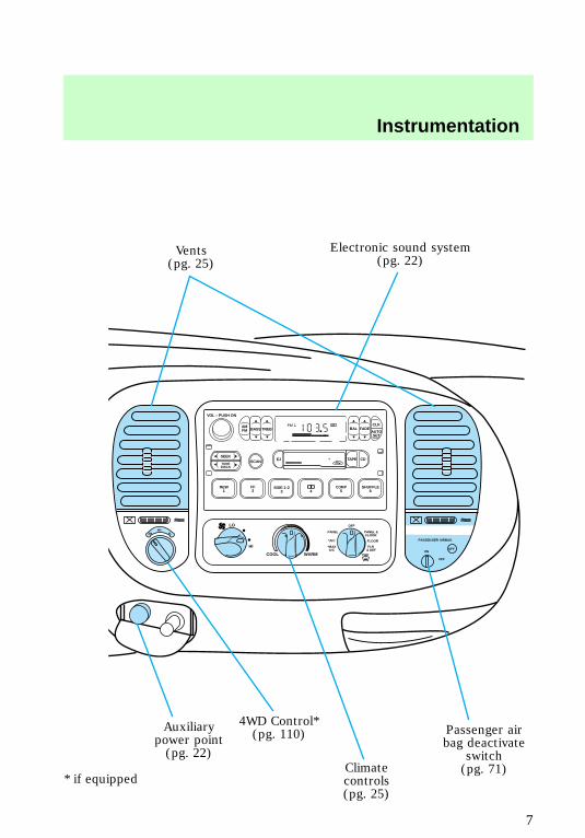
Vents(pg. 25)
Electronic sound system(pg. 22)
Passenger airbag deactivate
switch(pg. 71)Climate
controls(pg. 25)
4WD Control*(pg. 110)Auxiliary
power point(pg. 22)
* if equipped
f12_inst_warn_lights
Instrumentation
7
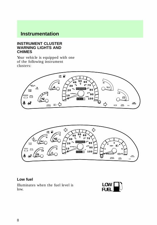
INSTRUMENT CLUSTERWARNING LIGHTS ANDCHIMESYour vehicle is equipped with oneof the following instrumentclusters:
Low fuelIlluminates when the fuel level islow.
MPH
10
50
30 7040
80
120
140
180
40
20
0 100
90
60
80
60 100
20 km/h
0 0 1 0
000005C
H
E
F
LOWRANGE
DOORAJAR
LOWFUEL
MPH
10
50
30 7040
80
120
140
180
40
20
0 100
90
60
80
60 100
20 km/h
0 0 1 0
000005C
H
E
F
LOWRANGE
4x4FUELRESET
CHECKENGINE
ABS
DOORAJAR
LOWFUEL
L
H
18
8!
BRAKE
3
10
50
30 7040
80
120
140
40
20
0 100
90
60
80
60 100
20 km/h
0 0 1 0
0000052 4
5
60
1
L
H
C
H
E
F
8
18
THEFT
RPMx1000LOW
RANGE
4x4FUELRESET
CHECKENGINE
ABS
DOORAJAR
LOWFUEL
3
10
50
30 7040
80
120
140
40
20
0 100
90
60
80
60 100
20 km/h
0 0 1 0
0000052 4
5
60
1
L
H
C
H
E
F
8
18
THEFT
RPMx1000 ABS
BRAKE
LOWFUEL
!
LOWFUEL
f12_low_fuel
f12_eng_cool_temp
Instrumentation
8
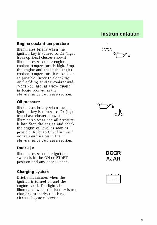
Engine coolant temperatureIlluminates briefly when theignition key is turned to On (lightfrom optional cluster shown).Illuminates when the enginecoolant temperature is high. Stopthe engine and check the enginecoolant temperature level as soonas possible. Refer to Checkingand adding engine coolant andWhat you should know aboutfail-safe cooling in theMaintenance and care section.
Oil pressureIlluminates briefly when theignition key is turned to On (lightfrom base cluster shown).Illuminates when the oil pressureis low. Stop the engine and checkthe engine oil level as soon aspossible. Refer to Checking andadding engine oil in theMaintenance and care section.
Door ajarIlluminates when the ignitionswitch is in the ON or STARTposition and any door is open.
Charging systemBriefly illuminates when theignition is turned on and theengine is off. The light alsoilluminates when the battery is notcharging properly, requiringelectrical system service.
DOORAJAR
f12_oil_pressure
com_door-ajar.02
com_charging_system.01
com_brake_system.01
Instrumentation
9
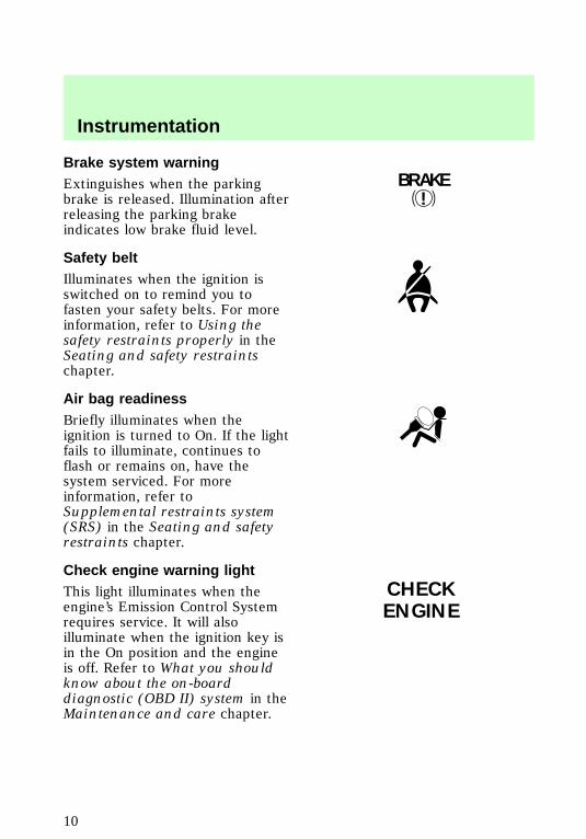
Brake system warningExtinguishes when the parkingbrake is released. Illumination afterreleasing the parking brakeindicates low brake fluid level.
Safety beltIlluminates when the ignition isswitched on to remind you tofasten your safety belts. For moreinformation, refer to Using thesafety restraints properly in theSeating and safety restraintschapter.
Air bag readinessBriefly illuminates when theignition is turned to On. If the lightfails to illuminate, continues toflash or remains on, have thesystem serviced. For moreinformation, refer toSupplemental restraints system(SRS) in the Seating and safetyrestraints chapter.
Check engine warning lightThis light illuminates when theengine’s Emission Control Systemrequires service. It will alsoilluminate when the ignition key isin the On position and the engineis off. Refer to What you shouldknow about the on-boarddiagnostic (OBD II) system in theMaintenance and care chapter.
!BRAKE
CHECKENGINE
com_safety_belt.01
f12_air_bag_readiness
f12_check_engine
f12_tcil_light
Instrumentation
10
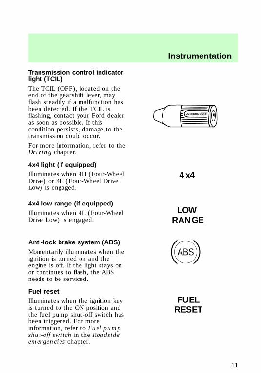
Transmission control indicatorlight (TCIL)The TCIL (OFF), located on theend of the gearshift lever, mayflash steadily if a malfunction hasbeen detected. If the TCIL isflashing, contact your Ford dealeras soon as possible. If thiscondition persists, damage to thetransmission could occur.
For more information, refer to theDriving chapter.
4x4 light (if equipped)Illuminates when 4H (Four-WheelDrive) or 4L (Four-Wheel DriveLow) is engaged.
4x4 low range (if equipped)Illuminates when 4L (Four-WheelDrive Low) is engaged.
Anti-lock brake system (ABS)Momentarily illuminates when theignition is turned on and theengine is off. If the light stays onor continues to flash, the ABSneeds to be serviced.
Fuel resetIlluminates when the ignition keyis turned to the ON position andthe fuel pump shut-off switch hasbeen triggered. For moreinformation, refer to Fuel pumpshut-off switch in the Roadsideemergencies chapter.
OVERDRIVE OFF
4x4
LOWRANGE
ABS
FUELRESET
f12_4x4_light
f12_4x4_low
com_anti-lock_brake.01
com_fuel_reset.01
com_anti-theft_alarm.01
Instrumentation
11
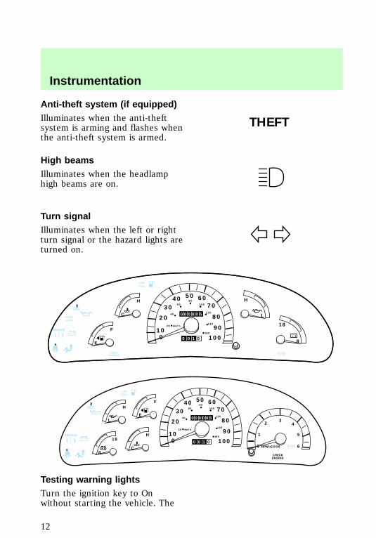
Anti-theft system (if equipped)Illuminates when the anti-theftsystem is arming and flashes whenthe anti-theft system is armed.
High beamsIlluminates when the headlamphigh beams are on.
Turn signalIlluminates when the left or rightturn signal or the hazard lights areturned on.
Testing warning lightsTurn the ignition key to Onwithout starting the vehicle. The
THEFT
! MPH
10
50
30 7040
80
120
140
180
40
20
0 100
90
60
80
60 100
20 km/h
0 0 1 0
000005C
H
E
F
DOORAJAR
LOWFUEL
MPH
CHECKENGINE
ABS
L
H
18
8
BRAKE
!
LOWFUEL
ABS
BRAKE
3
MPH
10
50
30 7040
80
120
140
180
40
20
0 100
90
60
80
60 100
20 km/h
0 0 1 0
0000052 4
5
60
1
L
H
C
H
E
F
8
18
RPMx1000
CHECKENGINE
com_high_beams.01
com_turn_signal.01
f12_testing_lights
Instrumentation
12
warning and indicator lights shownabove will illiminate for a brieftime. If any of these lights do notilluminate, contact your dealer forservice.
Headlamps on warning chimeSounds when the headlamps areon, the key is out of the ignitionand any door is opened.
Key-in-ignition warning chimeSounds when the key is left in theignition and any door is opened.The chime is not active when theignition key is in the On position.
Safety belt warning chimeFor information on the safety beltwarning chime, refer to theSeating and safety restraintschapter.
Supplemental restraint system(SRS) warning chimeFor information on the SRSwarning chime, refer to theSeating and safety restraintschapter.
f12_headlamps_on
f12_key_in_ignition
com_safety_chime.01
com_srs_chime.01
f12_gauges
Instrumentation
13
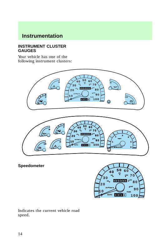
INSTRUMENT CLUSTERGAUGESYour vehicle has one of thefollowing instrument clusters:
Speedometer
Indicates the current vehicle roadspeed.
10
50
30 7040
80
120
140
180
40
20
0 100
90
60
80
60 100
20 km/h
0 0 1 0
000005 L
H
C
H
18
8E
F
E
F
3
10
50
30 7040
80
120
140
180
40
20
0 100
90
60
80
60 100
20 km/h
0 0 1 0
2 4
5
60
1
L
H
C
H
E
F
8
18
THEFT
RPMx1000
3
MPH
10
50
30 7040
80
120
140
180
40
20
0 100
90
60
80
60 100
20 km/h
0 0 1 0
0000052 4
5
60
1
L
H
C
H
E
F
8
18
THEFT
RPMx1000
MPH
50
40
80
120
140
180
4060 100
20 km/h
0 0 1 0
000005
MPH 10
50
3070
40
80
120
140
180
40
20
0 100
90
60
80
60 100
20 km/h
0 0 1 0
000005
f12_speedometer
com_tachometer.02
Instrumentation
14
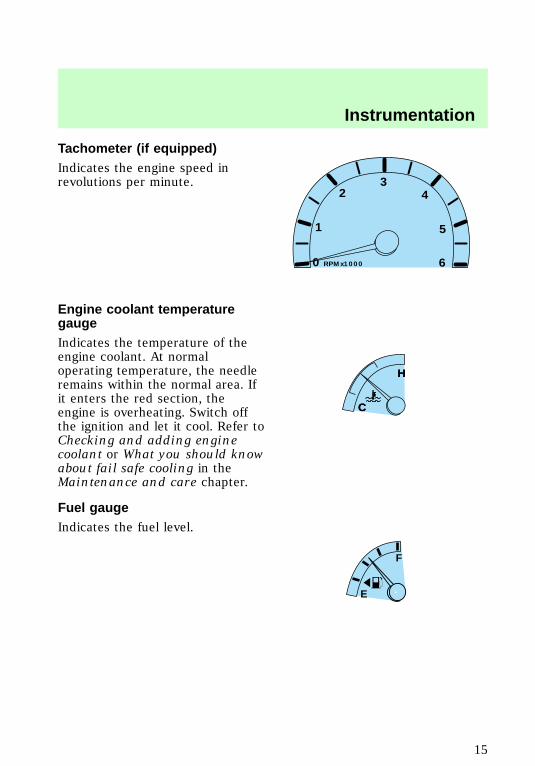
Tachometer (if equipped)Indicates the engine speed inrevolutions per minute.
Engine coolant temperaturegaugeIndicates the temperature of theengine coolant. At normaloperating temperature, the needleremains within the normal area. Ifit enters the red section, theengine is overheating. Switch offthe ignition and let it cool. Refer toChecking and adding enginecoolant or What you should knowabout fail safe cooling in theMaintenance and care chapter.
Fuel gaugeIndicates the fuel level.
0 RPMx1000
32 4
5
6
1
C
H
C
H
E
F
f12_engine_coolant
f12_fuel_gauge
f12_voltage_gauge
Instrumentation
15
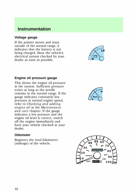
Voltage gaugeIf the pointer moves and staysoutside of the normal range, itindicates that the battery is notbeing charged. Have the vehicle’selectrical system checked by yourdealer as soon as possible.
Engine oil pressure gaugeThis shows the engine oil pressurein the system. Sufficient pressureexists as long as the needleremains in the normal range. If thegauge indicates constantly lowpressure at normal engine speed,refer to Checking and addingengine oil in the Maintenanceand care chapter. If the gaugeindicates a low pressure and theengine oil level is correct, switchoff the engine immediately andhave your vehicle checked at yourdealer.
OdometerRegisters the total kilometers(mileage) of the vehicle.
8
18
8
18
L
H
L
H
MPH
50
40
80
120
140
180
4060 100
20 km/h
0 0 1 0
000005
MPH 10
50
3070
40
80
120
140
180
40
20
0 100
90
60
80
60 100
20 km/h
0 0 1 0
000000000055
f12_oil_pressure
f12_odometer
f12_trip_odometer
Instrumentation
16
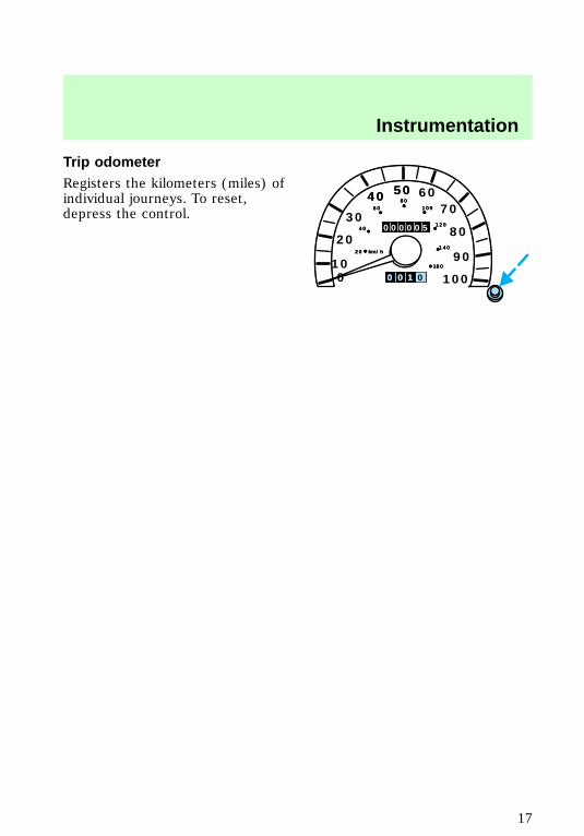
Trip odometerRegisters the kilometers (miles) ofindividual journeys. To reset,depress the control.
MPH
50
40
80
120
140
180
4060 100
20 km/h
0 0 1 0
000005
MPH 10
50
3070
40
80
120
140
180
40
20
0 100
90
60
80
60 100
20 km/h
0
000005
0 0 1
Instrumentation
17
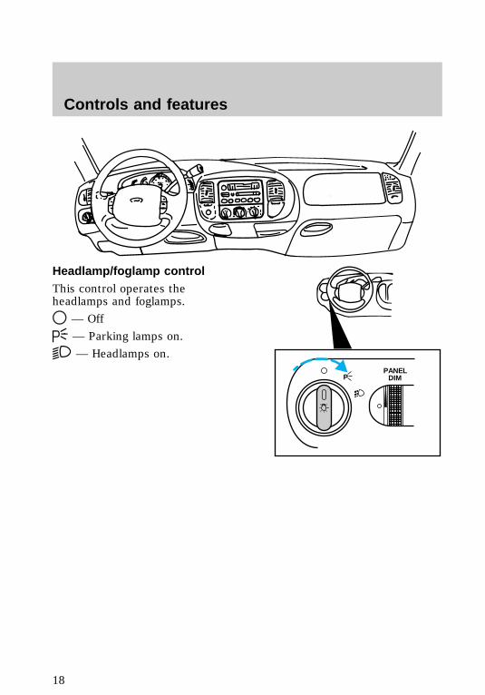
Headlamp/foglamp controlThis control operates theheadlamps and foglamps.
— Off
— Parking lamps on.
— Headlamps on.
PPANEL
DIM
f12_headlamp_switch
f12_foglamp_switch
Controls and features
18
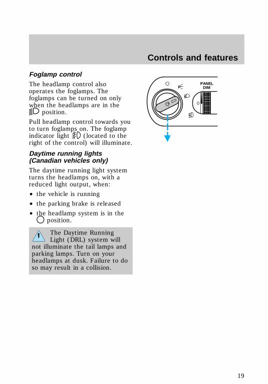
Foglamp controlThe headlamp control alsooperates the foglamps. Thefoglamps can be turned on onlywhen the headlamps are in the
position.
Pull headlamp control towards youto turn foglamps on. The foglampindicator light (located to theright of the control) will illuminate.
Daytime running lights(Canadian vehicles only)The daytime running light systemturns the headlamps on, with areduced light output, when:
• the vehicle is running
• the parking brake is released
• the headlamp system is in theposition.
The Daytime RunningLight (DRL) system will
not illuminate the tail lamps andparking lamps. Turn on yourheadlamps at dusk. Failure to doso may result in a collision.
PPANEL
DIM
f12_drl_lights
f12_dimmer_dial
Controls and features
19
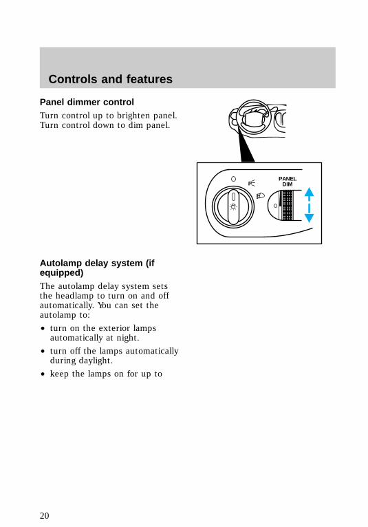
Panel dimmer controlTurn control up to brighten panel.Turn control down to dim panel.
Autolamp delay system (ifequipped)The autolamp delay system setsthe headlamp to turn on and offautomatically. You can set theautolamp to:
• turn on the exterior lampsautomatically at night.
• turn off the lamps automaticallyduring daylight.
• keep the lamps on for up to
PPANEL
DIM
f12_autolamp
Controls and features
20
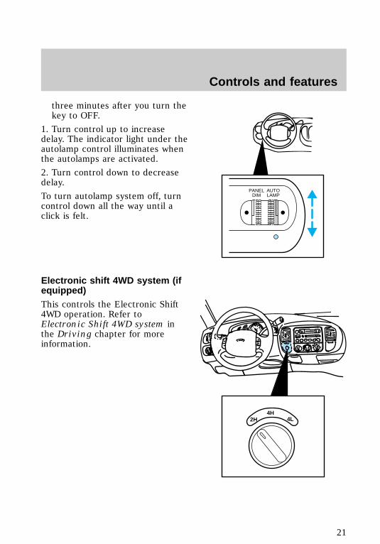
three minutes after you turn thekey to OFF.
1. Turn control up to increasedelay. The indicator light under theautolamp control illuminates whenthe autolamps are activated.
2. Turn control down to decreasedelay.
To turn autolamp system off, turncontrol down all the way until aclick is felt.
Electronic shift 4WD system (ifequipped)This controls the Electronic Shift4WD operation. Refer toElectronic Shift 4WD system inthe Driving chapter for moreinformation.
PANELDIM
AUTOLAMP
2H4H
4L
f12_4wd_switch
f12_power_point
Controls and features
21

Auxiliary power pointThis 12V power point is anadditional power source forelectrical accessories.
Do not plug optional electricalaccessories into the cigarettelighter. Use the power point.
Passenger air bag deactivateswitchThis switch must be used todeactivate the passenger air bagwhenever a child seat is used inthe right front or center frontpassenger seat position. Refer toPassenger air bag deactivateswitch in the Seating and safetyrestraints chapter.
Audio systemRefer to the “Audio Guide” in yourOwner’s Portfolio.
PASSENGER AIRBAG
ON
OFF
OFF
f12_pass_srs_deact
f12_audio
f12_fuel_shutoff
Controls and features
22
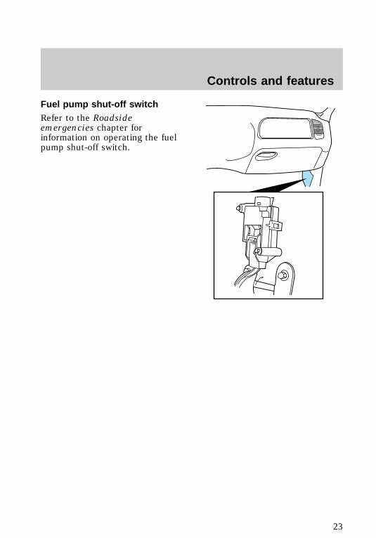
Fuel pump shut-off switchRefer to the Roadsideemergencies chapter forinformation on operating the fuelpump shut-off switch.
f12_air_suspension
Controls and features
23
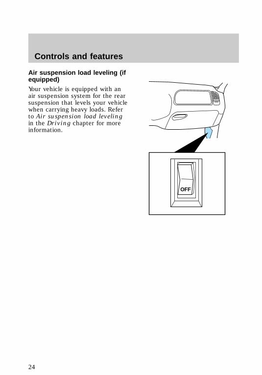
Air suspension load leveling (ifequipped)Your vehicle is equipped with anair suspension system for the rearsuspension that levels your vehiclewhen carrying heavy loads. Referto Air suspension load levelingin the Driving chapter for moreinformation.
OFF
f12_climate_controls
Controls and features
24
CLIMATE CONTROLS
Operating climate controls
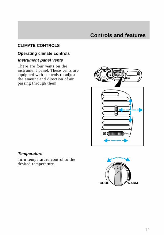
Instrument panel ventsThere are four vents on theinstrument panel. These vents areequipped with controls to adjustthe amount and direction of airpassing through them.
TemperatureTurn temperature control to thedesired temperature.
WARMCOOL
f12_climate_controls
f12_ip_vents
f12_temperature
f12_fan_speed
Controls and features
25

Fan speedTurn the fan speed control to thedesired speed.
Airflow and air conditioning (ifequipped)Turn the mode control to thedesired airflow position.
Controlling airflowSelect PANEL for air to flowthrough these vents:
LO
HI
FLR & DEF
MAXA/C
FLOOR
PANEL &FLOOR
DEF
OFF
PANEL
A/C
P
HI
LO OFF
*A/C
*MAXA/C
REW1
FF2
SIDE 1-23
FM 1 ST
VOL – PUSH ON
AMFM BASS TREB BAL FADE
AUTOSET
CLK
SEEK
TUNEDISCS
SCAN
4
DOLBY SYSTEM
EJ TAPE CD
COMP5
SHUFFLE6
f12_mode_control
f12_airflow
Controls and features
26
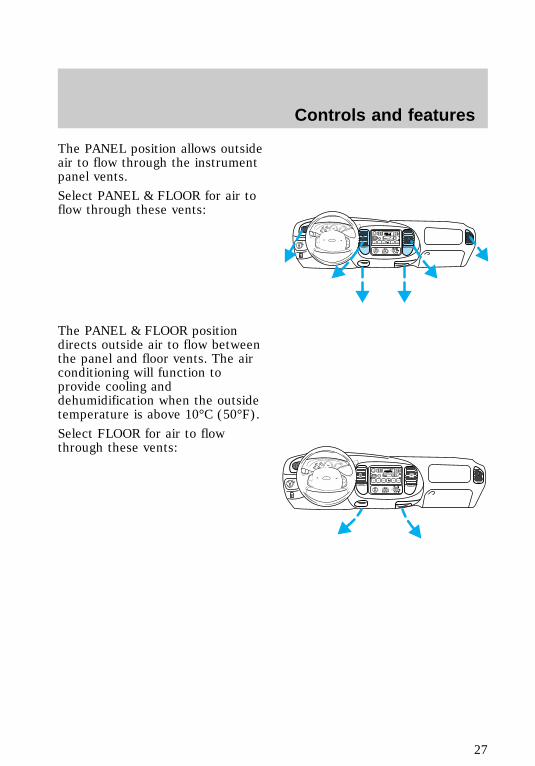
The PANEL position allows outsideair to flow through the instrumentpanel vents.
Select PANEL & FLOOR for air toflow through these vents:
The PANEL & FLOOR positiondirects outside air to flow betweenthe panel and floor vents. The airconditioning will function toprovide cooling anddehumidification when the outsidetemperature is above 10°C (50°F).
Select FLOOR for air to flowthrough these vents:
P
HI
LO OFF
*A/C
*MAXA/C
REW1
FF2
SIDE 1-23
FM 1 ST
VOL – PUSH ON
AMFM BASS TREB BAL FADE
AUTOSET
CLK
SEEK
TUNEDISCS
SCAN
4
DOLBY SYSTEM
EJ TAPE CD
COMP5
SHUFFLE6
P
HI
LO OFF
*A/C
*MAXA/C
REW1
FF2
SIDE 1-23
FM 1 ST
VOL – PUSH ON
AMFM BASS TREB BAL FADE
AUTOSET
CLK
SEEK
TUNEDISCS
SCAN
4
DOLBY SYSTEM
EJ TAPE CD
COMP5
SHUFFLE6
Controls and features
27
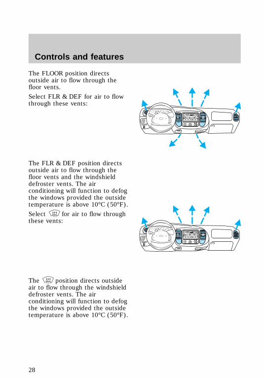
The FLOOR position directsoutside air to flow through thefloor vents.
Select FLR & DEF for air to flowthrough these vents:
The FLR & DEF position directsoutside air to flow through thefloor vents and the windshielddefroster vents. The airconditioning will function to defogthe windows provided the outsidetemperature is above 10°C (50°F).
Select for air to flow throughthese vents:
The position directs outsideair to flow through the windshielddefroster vents. The airconditioning will function to defogthe windows provided the outsidetemperature is above 10°C (50°F).
P
HI
LO OFF
*A/C
*MAXA/C
REW1
FF2
SIDE 1-23
FM 1 ST
VOL – PUSH ON
AMFM BASS TREB BAL FADE
AUTOSET
CLK
SEEK
TUNEDISCS
SCAN
4
DOLBY SYSTEM
EJ TAPE CD
COMP5
SHUFFLE6
P
HI
LO OFF
*A/C
*MAXA/C
REW1
FF2
SIDE 1-23
FM 1 ST
VOL – PUSH ON
AMFM BASS TREB BAL FADE
AUTOSET
CLK
SEEK
TUNEDISCS
SCAN
4
DOLBY SYSTEM
EJ TAPE CD
COMP5
SHUFFLE6
f12_air_conditioning
Controls and features
28
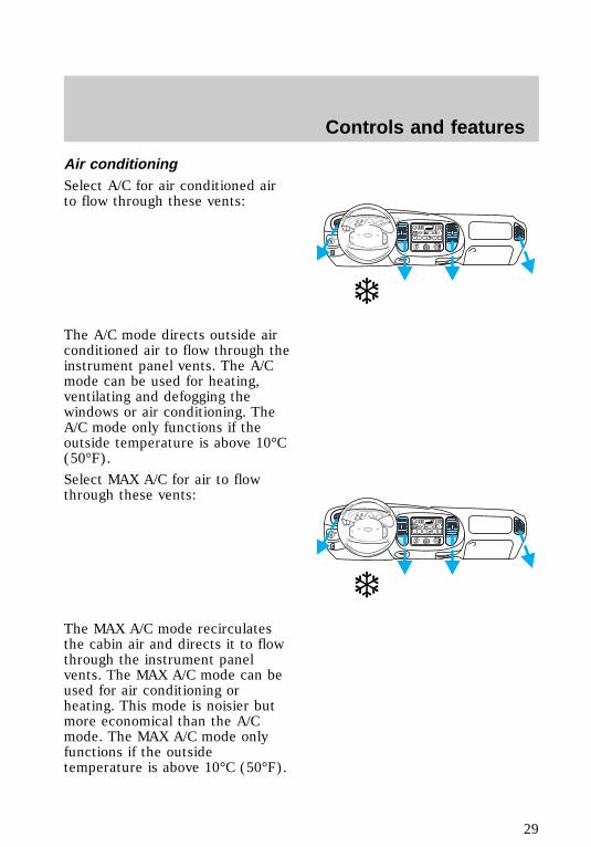
Air conditioningSelect A/C for air conditioned airto flow through these vents:
The A/C mode directs outside airconditioned air to flow through theinstrument panel vents. The A/Cmode can be used for heating,ventilating and defogging thewindows or air conditioning. TheA/C mode only functions if theoutside temperature is above 10°C(50°F).
Select MAX A/C for air to flowthrough these vents:
The MAX A/C mode recirculatesthe cabin air and directs it to flowthrough the instrument panelvents. The MAX A/C mode can beused for air conditioning orheating. This mode is noisier butmore economical than the A/Cmode. The MAX A/C mode onlyfunctions if the outsidetemperature is above 10°C (50°F).
P
HI
LO OFF
*A/C
*MAXA/C
REW1
FF2
SIDE 1-23
FM 1 ST
VOL – PUSH ON
AMFM BASS TREB BAL FADE
AUTOSET
CLK
SEEK
TUNEDISCS
SCAN
4
DOLBY SYSTEM
EJ TAPE CD
COMP5
SHUFFLE6
❄
P
HI
LO OFF
*A/C
*MAXA/C
REW1
FF2
SIDE 1-23
FM 1 ST
VOL – PUSH ON
AMFM BASS TREB BAL FADE
AUTOSET
CLK
SEEK
TUNEDISCS
SCAN
4
DOLBY SYSTEM
EJ TAPE CD
COMP5
SHUFFLE6
❄
Controls and features
29
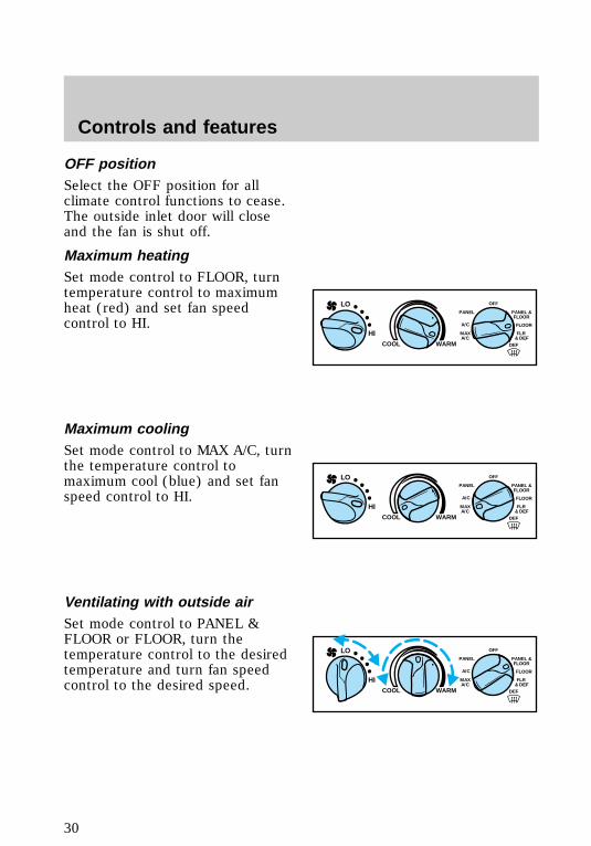
OFF positionSelect the OFF position for allclimate control functions to cease.The outside inlet door will closeand the fan is shut off.
Maximum heatingSet mode control to FLOOR, turntemperature control to maximumheat (red) and set fan speedcontrol to HI.
Maximum coolingSet mode control to MAX A/C, turnthe temperature control tomaximum cool (blue) and set fanspeed control to HI.
Ventilating with outside airSet mode control to PANEL &FLOOR or FLOOR, turn thetemperature control to the desiredtemperature and turn fan speedcontrol to the desired speed.
FLR & DEF
MAXA/C
FLOOR
PANEL &FLOOR
DEF
OFF
PANEL
A/C
WARMCOOL
LO
HI
FLR & DEF
MAXA/C
FLOOR
PANEL &FLOOR
DEF
OFF
PANEL
A/C
WARMCOOL
LO
HI
FLR & DEF
MAXA/C
FLOOR
PANEL &FLOOR
DEF
OFF
PANEL
A/C
WARMCOOL
LO
HI
f12_max_heatf12_max_cool
f12_ventilating
f12_defrosting
Controls and features
30
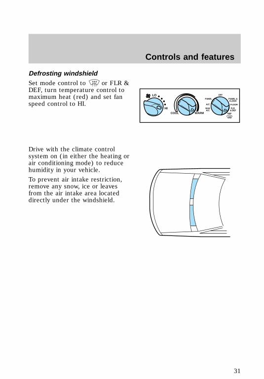
Defrosting windshieldSet mode control to or FLR &DEF, turn temperature control tomaximum heat (red) and set fanspeed control to HI.
Drive with the climate controlsystem on (in either the heating orair conditioning mode) to reducehumidity in your vehicle.
To prevent air intake restriction,remove any snow, ice or leavesfrom the air intake area locateddirectly under the windshield.
FLR & DEF
MAXA/C
FLOOR
PANEL &FLOOR
DEF
OFF
PANEL
A/C
WARMCOOL
LO
HI
f12_column_overall
Controls and features
31
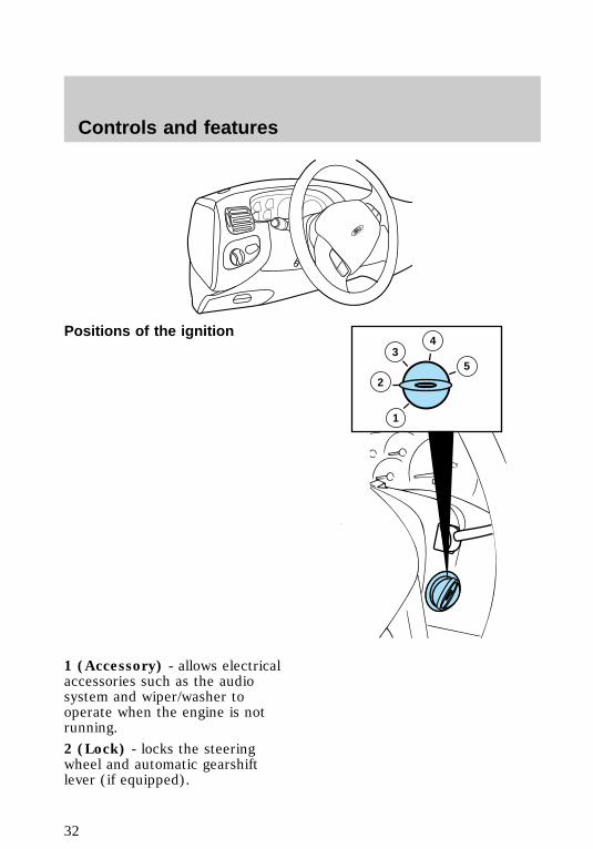
Positions of the ignition
1 (Accessory) - allows electricalaccessories such as the audiosystem and wiper/washer tooperate when the engine is notrunning.
2 (Lock) - locks the steeringwheel and automatic gearshiftlever (if equipped).
35
2
4
1
f12_ignition_positions
Controls and features
32
3 (Off) - shuts off the engine andall accessories without locking thesteering wheel.
4 (On) - tests the warning lights.Key remains here when engine isrunning.
5 (Start) - cranks the engine. Keyreturns to 4(On) when released.
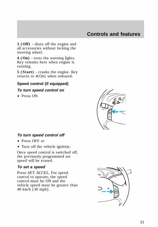
Speed control (if equipped)
To turn speed control on• Press ON
To turn speed control off• Press OFF or
• Turn off the vehicle ignition.
Once speed control is switched off,the previously programmed setspeed will be erased.
To set a speedPress SET ACCEL. For speedcontrol to operate, the speedcontrol must be ON and thevehicle speed must be greater than48 km/h (30 mph).
ON
OFF
RES
SETACCEL
COAST
f12_speed_cont
com_speed_on.01
com_speed_off.01
com_set_speed.01
Controls and features
33
If you drive up or down a steephill, your vehicle speed may varymomentarily slower or faster thanthe set speed. This is normal.
Speed control cannot reduce thevehicle speed if it increases abovethe set speed on a downhill. Ifyour vehicle speed is faster thanthe set speed while driving on adownhill in Overdrive, you maywant to shift to the next lowergear to reduce your vehicle speed.
If your vehicle slows downs morethan 16 km/h (10 mph) below yourset speed on an uphill, your speedcontrol will disengage. This isnormal. Pressing RES willre-engage it.
Do not use the speedcontrol in heavy traffic or
on roads that are winding,slippery, or unpaved.
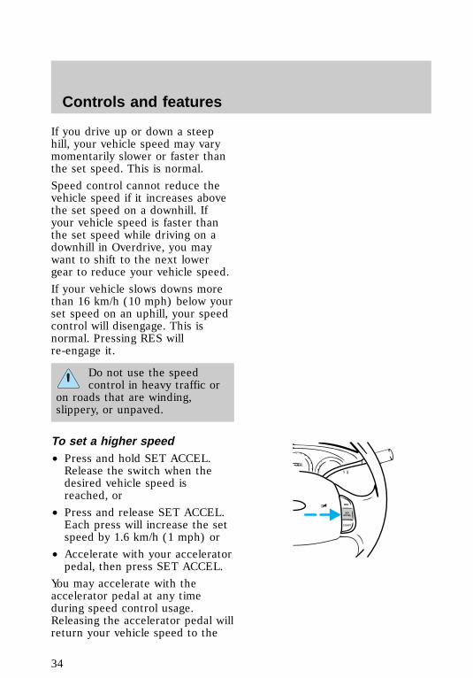
To set a higher speed• Press and hold SET ACCEL.Release the switch when thedesired vehicle speed isreached, or
• Press and release SET ACCEL.Each press will increase the setspeed by 1.6 km/h (1 mph) or
• Accelerate with your acceleratorpedal, then press SET ACCEL.
You may accelerate with theaccelerator pedal at any timeduring speed control usage.Releasing the accelerator pedal willreturn your vehicle speed to the
RES
SETACCEL
COAST
com_speed_up.01
Controls and features
34
previously programmed set speed.
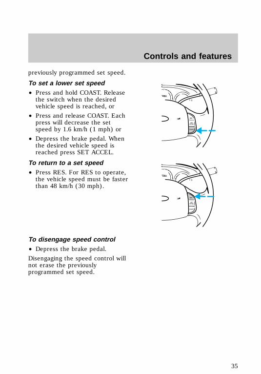
To set a lower set speed• Press and hold COAST. Releasethe switch when the desiredvehicle speed is reached, or
• Press and release COAST. Eachpress will decrease the setspeed by 1.6 km/h (1 mph) or
• Depress the brake pedal. Whenthe desired vehicle speed isreached press SET ACCEL.
To return to a set speed• Press RES. For RES to operate,the vehicle speed must be fasterthan 48 km/h (30 mph).
To disengage speed control• Depress the brake pedal.
Disengaging the speed control willnot erase the previouslyprogrammed set speed.
RES
SETACCEL
COAST
RES
SETACCEL
COAST
com_slow_down.01
com_resume_feature.01
com_disengage_speed_control.01
f12_wiper_washer
Controls and features
35
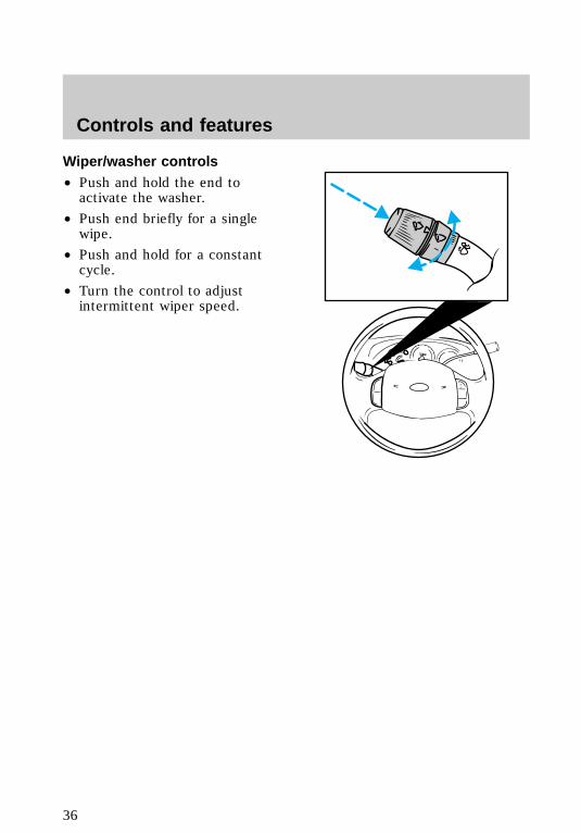
Wiper/washer controls• Push and hold the end toactivate the washer.
• Push end briefly for a singlewipe.
• Push and hold for a constantcycle.
• Turn the control to adjustintermittent wiper speed.
f12_high_beamsControls and features
36
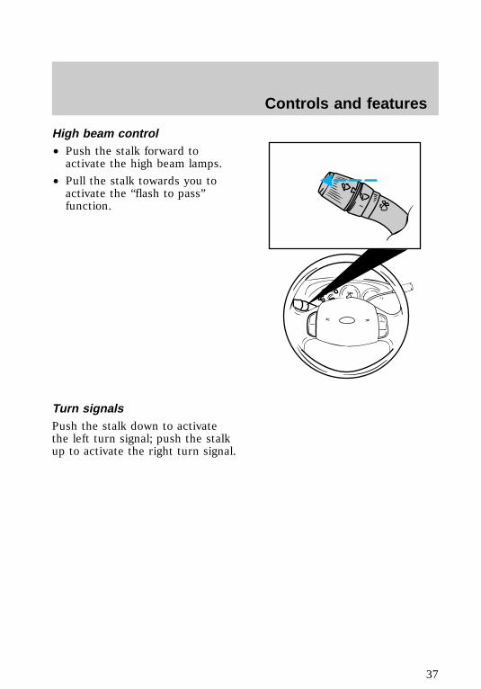
High beam control• Push the stalk forward toactivate the high beam lamps.
• Pull the stalk towards you toactivate the “flash to pass”function.
Turn signalsPush the stalk down to activatethe left turn signal; push the stalkup to activate the right turn signal.
f12_overdrive
Controls and features
37
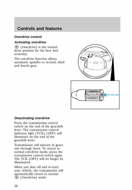
Overdrive control
Activating overdriveD (Overdrive) is the normaldrive position for the best fueleconomy.
The overdrive function allowsautomatic upshifts to second, thirdand fourth gear.
Deactivating overdrivePress the transmission controlswitch on the end of the gearshiftlever. The transmission controlindicator light (TCIL) (OFF) willilluminate on the end of thegearshift lever.
Transmission will operate in gearsone through three. To return tonormal overdrive mode, press thetransmission control switch again.The TCIL (OFF) will no longer beilluminated.
When you shut off and re-startyour vehicle, the transmission willautomatically return to normal
D (Overdrive) mode.
OVERDRIVE OFF
f12_activate_od
f12_deactivate_od
Controls and features
38
Deactivate overdrive wheneverdriving conditions (i.e., city traffic,hilly terrain, etc.) cause thetransmission to shift excessivelybetween D (Overdrive) andD(Drive) ranges. Also deactivate
D (Overdrive) when:
• driving with a heavy load
• towing a trailer up or downsteep hills
• additional engine braking isdesired.
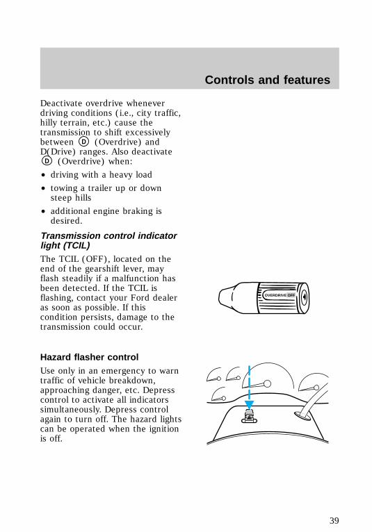
Transmission control indicatorlight (TCIL)The TCIL (OFF), located on theend of the gearshift lever, mayflash steadily if a malfunction hasbeen detected. If the TCIL isflashing, contact your Ford dealeras soon as possible. If thiscondition persists, damage to thetransmission could occur.
Hazard flasher controlUse only in an emergency to warntraffic of vehicle breakdown,approaching danger, etc. Depresscontrol to activate all indicatorssimultaneously. Depress controlagain to turn off. The hazard lightscan be operated when the ignitionis off.
OVERDRIVE OFF
f12_tcil_light
f12_hazard
f12_tilt_steer
Controls and features
39
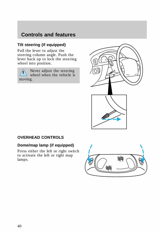
Tilt steering (if equipped)Pull the lever to adjust thesteering column angle. Push thelever back up to lock the steeringwheel into position.
Never adjust the steeringwheel when the vehicle is
moving.
OVERHEAD CONTROLS
Dome/map lamp (if equipped)Press either the left or right switchto activate the left or right maplamps.
f12_overhead_overall
f12_domemap_lampf12_illuminated_entry
Controls and features
40
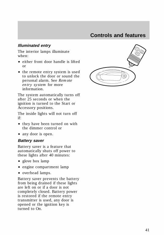
Illuminated entryThe interior lamps illuminatewhen:
• either front door handle is liftedor
• the remote entry system is usedto unlock the door or sound thepersonal alarm. See Remoteentry system for moreinformation.
The system automatically turns offafter 25 seconds or when theignition is turned to the Start orAccessory positions.
The inside lights will not turn offif:
• they have been turned on withthe dimmer control or
• any door is open.
Battery saverBattery saver is a feature thatautomatically shuts off power tothese lights after 40 minutes:
• glove box lamp
• engine compartment lamp
• overhead lamps.
Battery saver prevents the batteryfrom being drained if these lightsare left on or if a door is notcompletely closed. Battery poweris restored if the remote entrytransmitter is used, any door isopened or the ignition key isturned to On.
LOCK
UNLOCKPANIC
f12_battery_saver
Controls and features
41
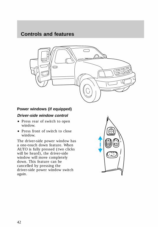
Power windows (if equipped)
Driver-side window control• Press rear of switch to openwindow.
• Press front of switch to closewindow.
The driver-side power window hasa one-touch down feature. WhenAUTO is fully pressed (two clickswill be heard), the driver-sidewindow will move completelydown. This feature can becancelled by pressing thedriver-side power window switchagain.
L U
AUTO
L R
f12_driver_control
f12_pass_control
Controls and features
42
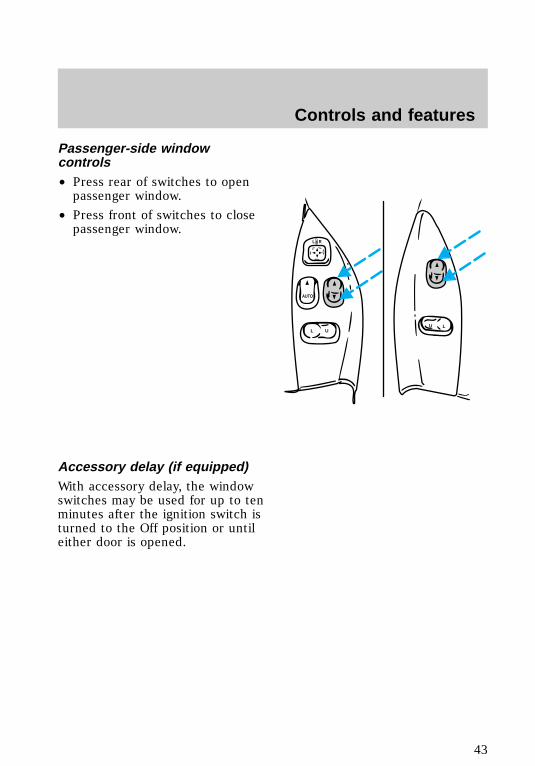
Passenger-side windowcontrols• Press rear of switches to openpassenger window.
• Press front of switches to closepassenger window.
Accessory delay (if equipped)With accessory delay, the windowswitches may be used for up to tenminutes after the ignition switch isturned to the Off position or untileither door is opened.
L U
AUTO
L R
LU
f12_acc_delay
f12_power_locks
Controls and features
43

Power locks (if equipped)
Driver and passenger controls• Press L to lock both doors.
• Press U to unlock both doors.
Dual electric remote controlmirrors (if equipped)1. Select driver or passengermirror by moving selector lever left(L) for driver or right (R) forpassenger.
2. Move the mirror control untilmirror reaches desired position.
3. Move selector lever to center to“lock” position.
L U
AUTO
L R
LU
L U
AUTO
L R
f12_driver_control
f12_remote_mirrors
Controls and features
44
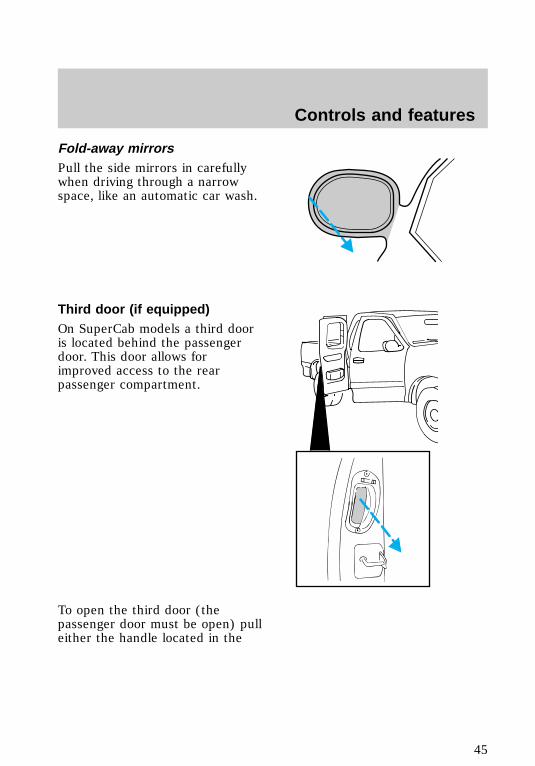
Fold-away mirrorsPull the side mirrors in carefullywhen driving through a narrowspace, like an automatic car wash.
Third door (if equipped)On SuperCab models a third dooris located behind the passengerdoor. This door allows forimproved access to the rearpassenger compartment.
To open the third door (thepassenger door must be open) pulleither the handle located in the
f12_third_door
Controls and features
45
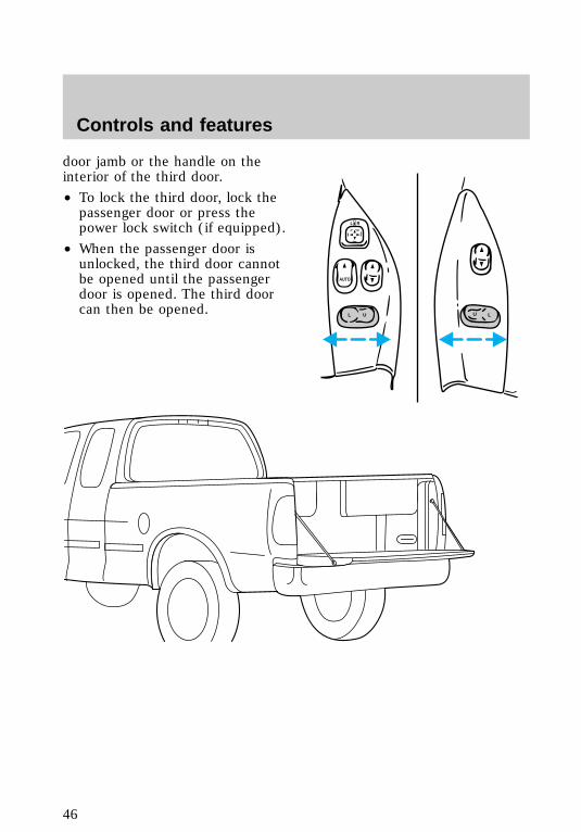
door jamb or the handle on theinterior of the third door.
• To lock the third door, lock thepassenger door or press thepower lock switch (if equipped).
• When the passenger door isunlocked, the third door cannotbe opened until the passengerdoor is opened. The third doorcan then be opened.
L U
AUTO
L R
LU
f12_trunk_overall
Controls and features
46
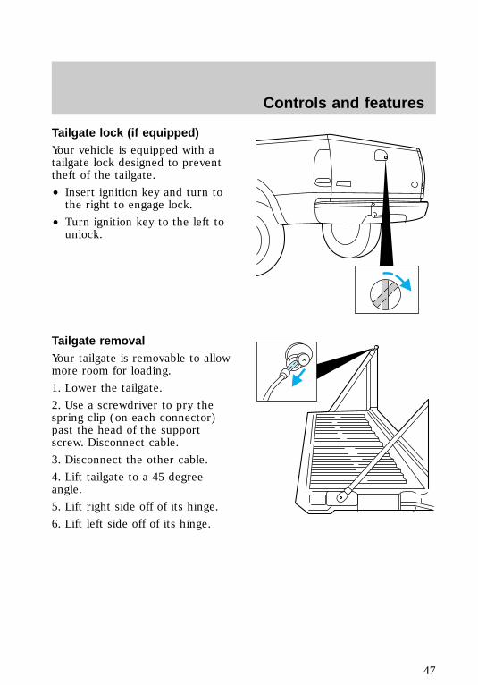
Tailgate lock (if equipped)Your vehicle is equipped with atailgate lock designed to preventtheft of the tailgate.
• Insert ignition key and turn tothe right to engage lock.
• Turn ignition key to the left tounlock.
Tailgate removalYour tailgate is removable to allowmore room for loading.
1. Lower the tailgate.
2. Use a screwdriver to pry thespring clip (on each connector)past the head of the supportscrew. Disconnect cable.
3. Disconnect the other cable.
4. Lift tailgate to a 45 degreeangle.
5. Lift right side off of its hinge.
6. Lift left side off of its hinge.
f12_tailgate_lock
f12_tailgate_removal
f12_antitheft
Controls and features
47
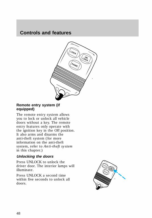
Remote entry system (ifequipped)The remote entry system allowsyou to lock or unlock all vehicledoors without a key. The remoteentry features only operate withthe ignition key in the Off position.It also arms and disarms theanti-theft system (for moreinformation on the anti-theftsystem, refer to Anti-theft systemin this chapter.)
Unlocking the doorsPress UNLOCK to unlock thedriver door. The interior lamps willilluminate.
Press UNLOCK a second timewithin five seconds to unlock alldoors.
LOCK
PANIC
UNLOCK
LOCK
PANIC
UNLOCK
f12_remote_entry
f12_unlocking_doors
f12_locking_doors
Controls and features
48
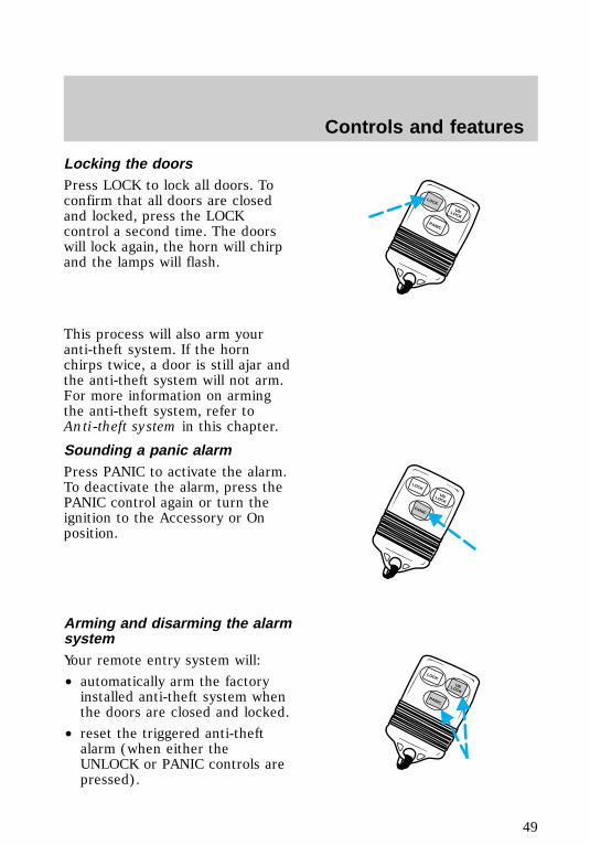
Locking the doorsPress LOCK to lock all doors. Toconfirm that all doors are closedand locked, press the LOCKcontrol a second time. The doorswill lock again, the horn will chirpand the lamps will flash.
This process will also arm youranti-theft system. If the hornchirps twice, a door is still ajar andthe anti-theft system will not arm.For more information on armingthe anti-theft system, refer toAnti-theft system in this chapter.
Sounding a panic alarmPress PANIC to activate the alarm.To deactivate the alarm, press thePANIC control again or turn theignition to the Accessory or Onposition.
Arming and disarming the alarmsystemYour remote entry system will:
• automatically arm the factoryinstalled anti-theft system whenthe doors are closed and locked.
• reset the triggered anti-theftalarm (when either theUNLOCK or PANIC controls arepressed).
PANIC
UNLOCK
LOCK
LOCK
PANIC
UNLOCK
PANIC
UNLOCK
LOCK
f12_sounding_panic
f12_arm_disarm_system
Controls and features
49

The remote entry system may notarm and disarm non-factoryinstalled anti-theft systems.
Replacing the batteriesThe transmitter is powered by twocoin type three-volt lithiumbatteries. A decrease in operatingrange can be caused by:
• battery failure
• weather conditions
• structures around the vehicle.
Replacement batteries for theremote entry transmitters may bepurchased at pharmacies, watchstores or at authorized dealers.
To replace the batteries:
1. Twist a thin coin between thetwo halves of the transmitter. DONOT TAKE THE FRONT PART OFTHE TRANSMITTER APART.
2. Place the positive (+) side ofthe new batteries down.
3. Snap the two halves backtogether.
Replacing lost transmittersTake all your vehicle’s transmittersto your dealer for reprogrammingif:
• a transmitter is lost or
• you want to purchase additionaltransmitters (up to four total)
Additional information aboutremote entryThis device complies with Part 15of the FCC rules. Operation is
f12_replacing_batteries
f12_fcc_rule
Controls and features
50
subject to the following twoconditions: (1) This device maynot cause harmful interference,and (2) This device must acceptany interference received,including interference that maycause undesired operation.
Anti-theft system (if equipped)When armed, the anti-theft systemprevents unauthorized entry intoyour vehicle.
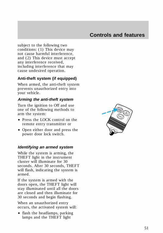
Arming the anti-theft systemTurn the ignition to Off and useone of the following methods toarm the system:
• Press the LOCK control on theremote entry transmitter or
• Open either door and press thepower door lock switch.
Identifying an armed systemWhile the system is arming, theTHEFT light in the instrumentcluster will illuminate for 30seconds. After 30 seconds, THEFTwill flash, indicating the system isarmed.
If the system is armed with thedoors open, the THEFT light willstay illuminated until all the doorsare closed and then illuminate for30 seconds and begin flashing.
When an unauthorized entryoccurs, the activated system will:
• flash the headlamps, parkinglamps and the THEFT light
PANIC
UNLOCK
LOCK
f12_arming_anti_theft
f12_identifying_armed
Controls and features
51
• sound the horn
• prohibit the vehicle fromstarting.
The flashing headlamps and thehonking horn automatically shutoff after about three minutes andwill remain off unless anotherunauthorized entry is attempted.However, the vehicle will not startuntil the system is disarmed.
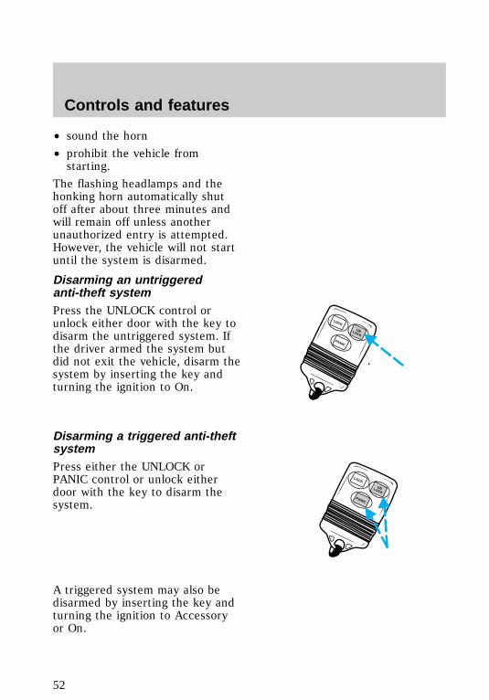
Disarming an untriggeredanti-theft systemPress the UNLOCK control orunlock either door with the key todisarm the untriggered system. Ifthe driver armed the system butdid not exit the vehicle, disarm thesystem by inserting the key andturning the ignition to On.
Disarming a triggered anti-theftsystemPress either the UNLOCK orPANIC control or unlock eitherdoor with the key to disarm thesystem.
A triggered system may also bedisarmed by inserting the key andturning the ignition to Accessoryor On.
LOCK
PANIC
UNLOCK
PANIC
UNLOCK
LOCK
f12_disarming_untriggered
Controls and features
52
SEATING
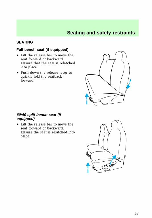
Full bench seat (if equipped)• Lift the release bar to move theseat forward or backward.Ensure that the seat is relatchedinto place.
• Push down the release lever toquickly fold the seatbackforward.
60/40 split bench seat (ifequipped)• Lift the release bar to move theseat forward or backward.Ensure the seat is relatched intoplace.
f12_adjusting_bench
f12_split_bench
Seating and safety restraints
53
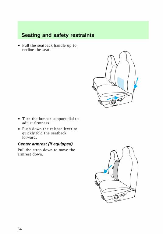
• Pull the seatback handle up torecline the seat.
• Turn the lumbar support dial toadjust firmness.
• Push down the release lever toquickly fold the seatbackforward.
Center armrest (if equipped)Pull the strap down to move thearmrest down.
f12_adjust_man_bucket
Seating and safety restraints
54
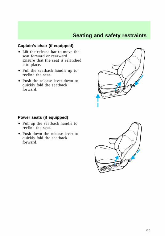
Captain’s chair (if equipped)• Lift the release bar to move theseat forward or rearward.Ensure that the seat is relatchedinto place.
• Pull the seatback handle up torecline the seat.
• Push the release lever down toquickly fold the seatbackforward.
Power seats (if equipped)• Pull up the seatback handle torecline the seat.
• Push down the release lever toquickly fold the seatbackforward.
f12_adjust_power_seat
Seating and safety restraints
55
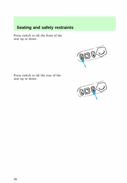
Press switch to tilt the front of theseat up or down.
Press switch to tilt the rear of theseat up or down.
Seating and safety restraints
56
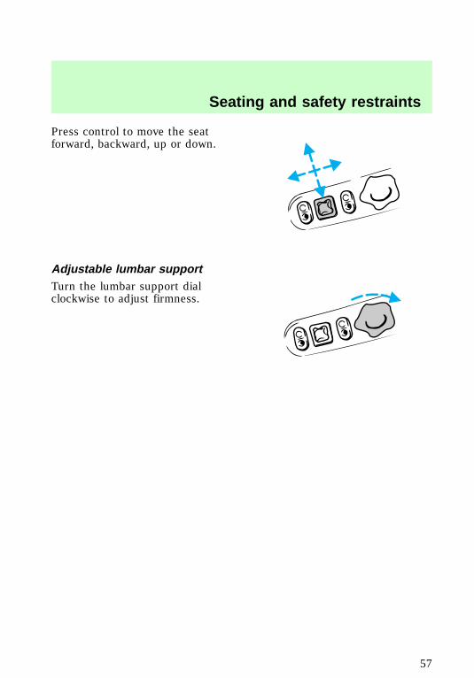
Press control to move the seatforward, backward, up or down.
Adjustable lumbar supportTurn the lumbar support dialclockwise to adjust firmness.
f12_adjust_lumbar
f12_rear_bench
Seating and safety restraints
57
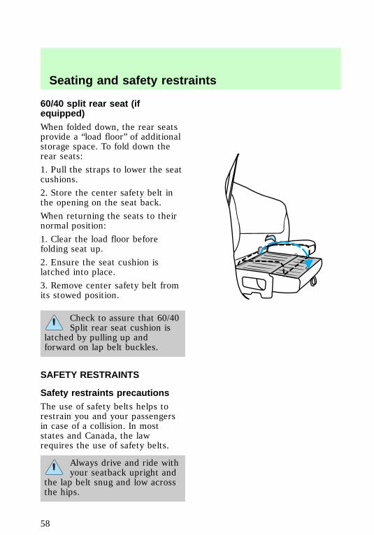
60/40 split rear seat (ifequipped)When folded down, the rear seatsprovide a “load floor” of additionalstorage space. To fold down therear seats:
1. Pull the straps to lower the seatcushions.
2. Store the center safety belt inthe opening on the seat back.
When returning the seats to theirnormal position:
1. Clear the load floor beforefolding seat up.
2. Ensure the seat cushion islatched into place.
3. Remove center safety belt fromits stowed position.
Check to assure that 60/40Split rear seat cushion is
latched by pulling up andforward on lap belt buckles.
SAFETY RESTRAINTS
Safety restraints precautionsThe use of safety belts helps torestrain you and your passengersin case of a collision. In moststates and Canada, the lawrequires the use of safety belts.
Always drive and ride withyour seatback upright and
the lap belt snug and low acrossthe hips.
f12_seat_belts
f12_safety_res_prec
Seating and safety restraints
58
All occupants of thevehicle, including the
driver, should always wear theirsafety belts.
To prevent the risk ofinjury, make sure children
sit where they can be properlyrestrained.
It is extremely dangerousto ride in a cargo area,
inside or outside of a vehicle. Ina collision, people riding in theseareas are more likely to beseriously injured or killed. Do notallow people to ride in any areaof your vehicle that is notequipped with seats and safetybelts. Be sure everyone in yourvehicle is in a seat and using asafety belt properly.
f12_using_sr_properly
Seating and safety restraints
59
Using safety restraints properly
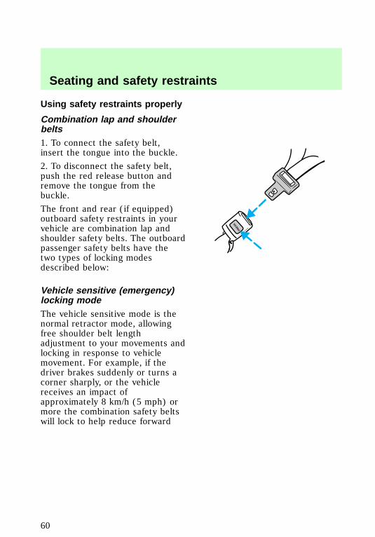
Combination lap and shoulderbelts1. To connect the safety belt,insert the tongue into the buckle.
2. To disconnect the safety belt,push the red release button andremove the tongue from thebuckle.
The front and rear (if equipped)outboard safety restraints in yourvehicle are combination lap andshoulder safety belts. The outboardpassenger safety belts have thetwo types of locking modesdescribed below:
Vehicle sensitive (emergency)locking modeThe vehicle sensitive mode is thenormal retractor mode, allowingfree shoulder belt lengthadjustment to your movements andlocking in response to vehiclemovement. For example, if thedriver brakes suddenly or turns acorner sharply, or the vehiclereceives an impact ofapproximately 8 km/h (5 mph) ormore the combination safety beltswill lock to help reduce forward
PRESS
f12_comb_lap_sh_belts
Seating and safety restraints
60
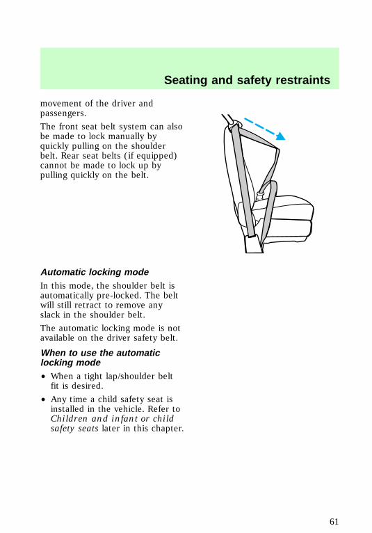
movement of the driver andpassengers.
The front seat belt system can alsobe made to lock manually byquickly pulling on the shoulderbelt. Rear seat belts (if equipped)cannot be made to lock up bypulling quickly on the belt.
Automatic locking modeIn this mode, the shoulder belt isautomatically pre-locked. The beltwill still retract to remove anyslack in the shoulder belt.
The automatic locking mode is notavailable on the driver safety belt.
When to use the automaticlocking mode• When a tight lap/shoulder beltfit is desired.
• Any time a child safety seat isinstalled in the vehicle. Refer toChildren and infant or childsafety seats later in this chapter.
f12_auto_lock_mode
f12_when_to_use_alr
f12_how_use_alr
Seating and safety restraints
61
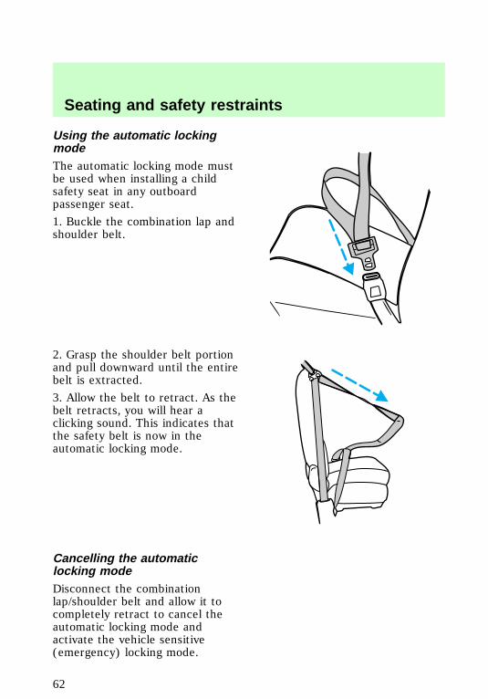
Using the automatic lockingmodeThe automatic locking mode mustbe used when installing a childsafety seat in any outboardpassenger seat.
1. Buckle the combination lap andshoulder belt.
2. Grasp the shoulder belt portionand pull downward until the entirebelt is extracted.
3. Allow the belt to retract. As thebelt retracts, you will hear aclicking sound. This indicates thatthe safety belt is now in theautomatic locking mode.
Cancelling the automaticlocking modeDisconnect the combinationlap/shoulder belt and allow it tocompletely retract to cancel theautomatic locking mode andactivate the vehicle sensitive(emergency) locking mode.
f12_cancel_alr
f12_front_sbelt_height_adjust
Seating and safety restraints
62
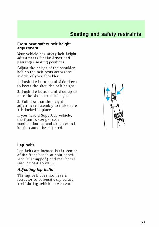
Front seat safety belt heightadjustmentYour vehicle has safety belt heightadjustments for the driver andpassenger seating positions.
Adjust the height of the shoulderbelt so the belt rests across themiddle of your shoulder.
1. Push the button and slide downto lower the shoulder belt height.
2. Push the button and slide up toraise the shoulder belt height.
3. Pull down on the heightadjustment assembly to make sureit is locked in place.
If you have a SuperCab vehicle,the front passenger seatcombination lap and shoulder beltheight cannot be adjusted.
Lap beltsLap belts are located in the centerof the front bench or split benchseat (if equipped) and rear benchseat (SuperCab only).
Adjusting lap beltsThe lap belt does not have aretractor to automatically adjustitself during vehicle movement.
f12_lap_belts
f12_adjusting_lap_belts
Seating and safety restraints
63
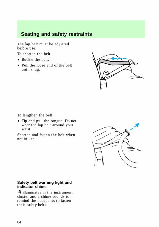
The lap belt must be adjustedbefore use.
To shorten the belt:
• Buckle the belt.
• Pull the loose end of the beltuntil snug.
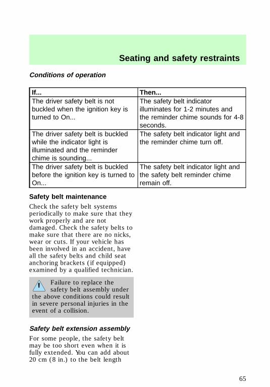
To lengthen the belt:
• Tip and pull the tongue. Do notwear the lap belt around yourwaist.
Shorten and fasten the belt whennot in use.
Safety belt warning light andindicator chime
illuminates in the instrumentcluster and a chime sounds toremind the occupants to fastentheir safety belts.
f12_sbelt_warning_chime
f12_cond_operation
Seating and safety restraints
64
Conditions of operation
If... Then...The driver safety belt is notbuckled when the ignition key isturned to On...
The safety belt indicatorilluminates for 1-2 minutes andthe reminder chime sounds for 4-8seconds.
The driver safety belt is buckledwhile the indicator light isilluminated and the reminderchime is sounding...
The safety belt indicator light andthe reminder chime turn off.
The driver safety belt is buckledbefore the ignition key is turned toOn...
The safety belt indicator light andthe safety belt reminder chimeremain off.
Safety belt maintenanceCheck the safety belt systemsperiodically to make sure that theywork properly and are notdamaged. Check the safety belts tomake sure that there are no nicks,wear or cuts. If your vehicle hasbeen involved in an accident, haveall the safety belts and child seatanchoring brackets (if equipped)examined by a qualified technician.
Failure to replace thesafety belt assembly under
the above conditions could resultin severe personal injuries in theevent of a collision.
Safety belt extension assemblyFor some people, the safety beltmay be too short even when it isfully extended. You can add about20 cm (8 in.) to the belt length
f12_sbelt_maint
f12_sbelt_extension
Seating and safety restraints
65

with a safety belt extensionassembly (part # 611C22). Safetybelt extensions are available at nocost from your Ford orLincoln/Mercury dealer.
Use only extensions manufacturedby the same supplier as the safetybelt. Manufacturer identification islocated at the end of the webbingon the label. Also, use the safetybelt extension only if the safetybelt is too short for you when fullyextended. Do not use extension tochange the fit of the shoulder beltacross the torso.
SUPPLEMENTAL RESTRAINTSYSTEM (SRS)
Important supplementalrestraint system (SRS)precautionsThe supplemental restraint systemis designed to:
• work with the safety belt toprotect the driver and rightfront passenger
• reduce certain upper bodyinjuries
Failure to follow theseinstructions will affect the
performance of the safety beltsand increase the risk of personalinjury.
f12_air_bags
com_important_precautions.01
Seating and safety restraints
66
The right front passengerair bag is not designed to
restrain occupants in the frontseating position.
Do not place objects ormount equipment on or
near the air bag covers that maycome into contact with aninflating air bag.
Do not attempt to service,repair, or modify the Air
Bag Supplemental RestraintSystem or its fuses. See yourFord or Lincoln-Mercury dealer.
Children and air bagsFor additional important safetyinformation, read all informationon safety restraints in this guide.
com_children.01
Seating and safety restraints
67

Children should always wear theirsafety belts. Failure to follow theseinstructions may increase the riskof injury in a collision.
Rear-facing child seats orinfant carriers should
never be placed in the frontseats.
How does the air bagsupplemental restraint systemwork?The SRS is designed to activatewhen the vehicle sustainssufficient longitudinal deceleration,similar to hitting a fixed barrierhead on at 12–24 km/h (8–14mph).
The fact that the air bags did notinflate in a collision does not meanthat something is wrong with thesystem. Rather, it means the forces
com_how_work.01Seating and safety restraints
68
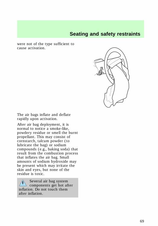
were not of the type sufficient tocause activation.
The air bags inflate and deflaterapidly upon activation.
After air bag deployment, it isnormal to notice a smoke-like,powdery residue or smell the burntpropellant. This may consist ofcornstarch, talcum powder (tolubricate the bag) or sodiumcompounds (e.g., baking soda) thatresult from the combustion processthat inflates the air bag. Smallamounts of sodium hydroxide maybe present which may irritate theskin and eyes, but none of theresidue is toxic.
Several air bag systemcomponents get hot after
inflation. Do not touch themafter inflation.
Seating and safety restraints
69
If the air bag is inflated,the air bag will not
function again and must bereplaced immediately. If theair bag is not replaced, theunrepaired area will increase therisk of injury in a collision.
The SRS consists of:
• driver and passenger air bagmodules (which include theinflators and air bags),
• one or more impact and safingsensors,
• a readiness light and tone
• and the electrical wiring whichconnects the components.
The diagnostic module monitors itsown internal circuits and thesupplemental air bag electricalsystem readiness (including theimpact sensors), the system wiring,the air bag system readiness light,the air bag back up power and theair bag ignitors.
Determining if the system isoperationalThe SRS uses a readiness light inthe instrument cluster or a tone toindicate the condition of thesystem. Refer to the Air bagreadiness section in theInstrumentation chapter. Routinemaintenance of the air bag is notrequired.
com_determing_operational.01
Seating and safety restraints
70
A difficulty with the system isindicated by one or more of thefollowing:
• The readiness light will eitherflash or stay lit.
• The readiness light will notilluminate immediately afterignition is turned on.
• A group of five beeps will beheard. The tone pattern willrepeat periodically until theproblem and light are repaired.
If any of these things happen, evenintermittently, have the SRSserviced at your dealership or by aqualified technician immediately.Unless serviced, the system maynot function properly in the eventof a collision.
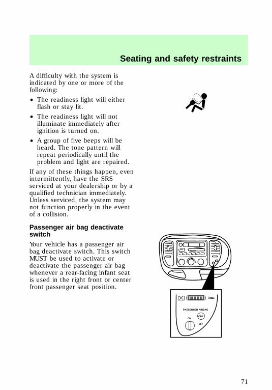
Passenger air bag deactivateswitchYour vehicle has a passenger airbag deactivate switch. This switchMUST be used to activate ordeactivate the passenger air bagwhenever a rear-facing infant seatis used in the right front or centerfront passenger seat position.
PASSENGER AIRBAG
ON
OFF
OFF
f12_srs_deactivate
Seating and safety restraints
71
Keep the passenger air bagturned on unless there is a
rear-facing infant seat installed inthe front seat. When thepassenger air bag switch isturned off, the passenger air bagwill not inflate in a collision.
If the passenger air bag switch isturned off, it increases thelikelihood of injury to forwardfacing occupants in the passengerseat.
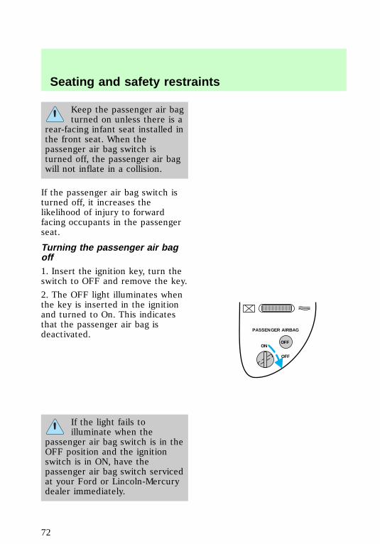
Turning the passenger air bagoff1. Insert the ignition key, turn theswitch to OFF and remove the key.
2. The OFF light illuminates whenthe key is inserted in the ignitionand turned to On. This indicatesthat the passenger air bag isdeactivated.
If the light fails toilluminate when the
passenger air bag switch is in theOFF position and the ignitionswitch is in ON, have thepassenger air bag switch servicedat your Ford or Lincoln-Mercurydealer immediately.
PASSENGER AIRBAG
ON
OFF
OFF
Seating and safety restraints
72
In order to avoidinadvertent deployment of
the passenger air bag, alwaysremove the ignition key from thepassenger air bag deactivateswitch.
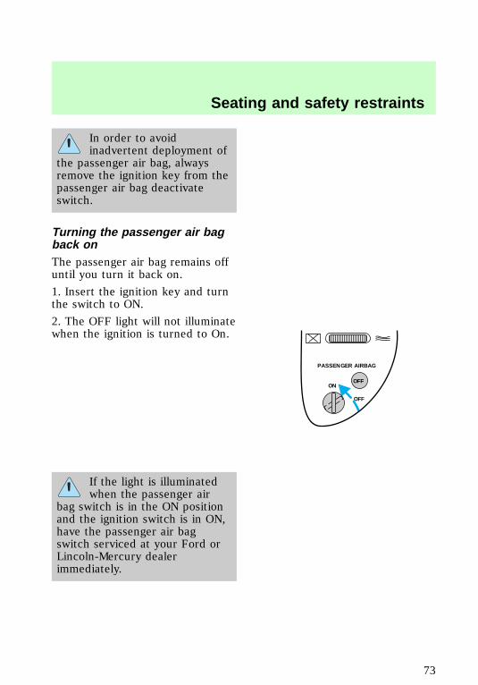
Turning the passenger air bagback onThe passenger air bag remains offuntil you turn it back on.
1. Insert the ignition key and turnthe switch to ON.
2. The OFF light will not illuminatewhen the ignition is turned to On.
If the light is illuminatedwhen the passenger air
bag switch is in the ON positionand the ignition switch is in ON,have the passenger air bagswitch serviced at your Ford orLincoln-Mercury dealerimmediately.
PASSENGER AIRBAG
ON
OFF
OFF
Seating and safety restraints
73
Keep the passenger air bagturned on unless there is a
rear-facing infant seat installed inthe front seat. When thepassenger air bag switch isturned off, the passenger air bagwill not inflate in a collision.
Disposal of air bags and air bagequipped vehiclesFor disposal of air bags or air bagequipped vehicles, see your localdealership or qualified technician.Air bags MUST BE disposed of byqualified personnel.
SAFETY RESTRAINTS FORCHILDREN
Important child restraintprecautionsYou are required by law to usesafety restraints for children in theU.S. and Canada. If small childrenride in your vehicle (generallychildren who are four years old oryounger and who weigh 18 kg [40lbs] or less), you must put them insafety seats made especially forchildren. Check your local andstate laws for specificrequirements regarding the safetyof children in your vehicle.
Never let a passenger holda child on his or her lap
while the vehicle is moving. Thepassenger cannot protect thechild from injury in a collision.
com_disposal.01
f12_child
f12_imp_childres_prec
Seating and safety restraints
74
Always follow the instructions andwarnings that come with any infantor child restraint you might use.
If possible, place children in therear seat of your vehicle. Accidentstatistics suggest that children aresafer when properly restrained inrear seating positions than whenthey are restrained in front seatingpositions.
Children and safety beltsChildren who are too large forchild safety seats (as specified byyour child safety seatmanufacturer) should always wearsafety belts.
Follow all the important safetyrestraint and air bag precautionsthat apply to adult passengers inyour vehicle.
If the shoulder belt portion of acombination lap and shoulder beltcan be positioned so it does notcross or rest in front of the child’sface or neck, the child should wearthe lap and shoulder belt. Movingthe child closer to the center ofthe vehicle may help provide agood shoulder belt fit.
If the shoulder belt cannot beproperly positioned:
• move the child to one of theseats with a lap belt only (ifequipped)
OR
• if the child is the proper size,restrain the child in a safetyseat.
com_safety_belts.01
Seating and safety restraints
75
Do not leave children,unreliable adults, or pets
unattended in your vehicle.
To improve the fit of lap andshoulder belts on children whohave outgrown child safety seats,Ford recommends use of abelt-positioning booster seat that islabelled as conforming to allFederal motor vehicle safetystandards. Belt-positioning boosterseats raise the child and provide ashorter, firmer seating cushion thatencourages safer seating postureand better fit of lap and shoulderbelts on the child. Abelt-positioning booster should beused if the shoulder belt rests infront of the child’s face or neck, orif the lap belt does not fit snuglyon both thighs, or if the thighs aretoo short to let the child sit all theway back on the seat cushionwhen the lower legs hang over theedge of the seat cushion. You maywish to discuss the special needsof your child with yourpediatrician.
com_safety_seats.01
Seating and safety restraints
76
Child and infant or child safetyseats
Carefully follow all of themanufacturer’s instructions
included with the safety seat youput in your vehicle. If you do notinstall and use the safety seatproperly, the child may beinjured in a sudden stop orcollision.
Ford recommends the use of achild safety seat having a toptether strap. Install the child safetyseat in a seating position which iscapable of providing a tetheranchorage. For more informationon top tether straps see Attachingsafety seats with tether straps inthis chapter.
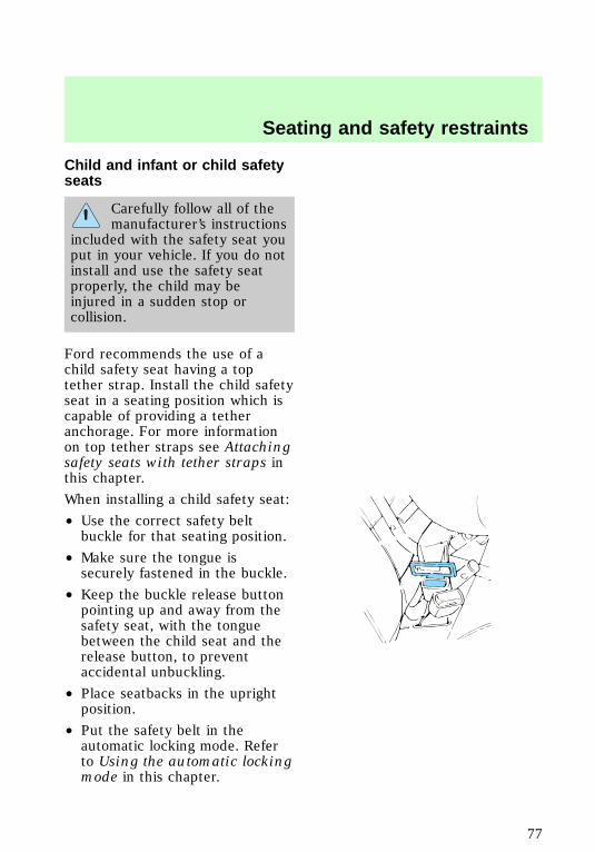
When installing a child safety seat:
• Use the correct safety beltbuckle for that seating position.
• Make sure the tongue issecurely fastened in the buckle.
• Keep the buckle release buttonpointing up and away from thesafety seat, with the tonguebetween the child seat and therelease button, to preventaccidental unbuckling.
• Place seatbacks in the uprightposition.
• Put the safety belt in theautomatic locking mode. Referto Using the automatic lockingmode in this chapter.
f12_installing_seats
Seating and safety restraints
77
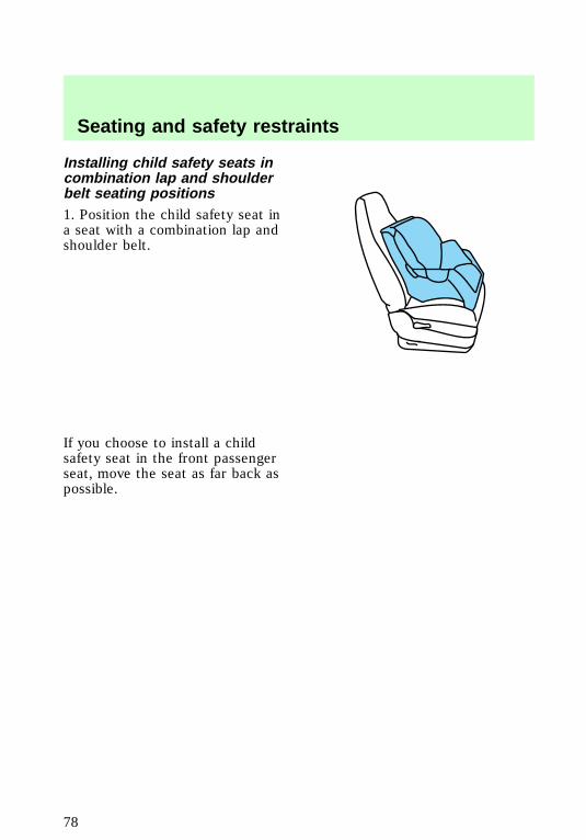
Installing child safety seats incombination lap and shoulderbelt seating positions1. Position the child safety seat ina seat with a combination lap andshoulder belt.
If you choose to install a childsafety seat in the front passengerseat, move the seat as far back aspossible.
Seating and safety restraints
78
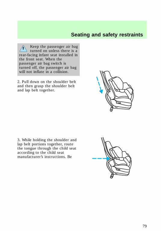
Keep the passenger air bagturned on unless there is a
rear-facing infant seat installed inthe front seat. When thepassenger air bag switch isturned off, the passenger air bagwill not inflate in a collision.
2. Pull down on the shoulder beltand then grasp the shoulder beltand lap belt together.
3. While holding the shoulder andlap belt portions together, routethe tongue through the child seataccording to the child seatmanufacturer’s instructions. Be
Seating and safety restraints
79

sure the belt webbing is nottwisted.
4. Insert the belt tongue into theproper buckle for that seatingposition until you hear and feel thelatch engage. Make sure thetongue is latched securely bypulling on it.
5. To put the retractor in theautomatic locking mode, grasp theshoulder portion of the belt and
PRESS
Seating and safety restraints
80
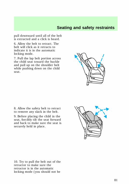
pull downward until all of the beltis extracted and a click is heard.
6. Allow the belt to retract. Thebelt will click as it retracts toindicate it is in the automaticlocking mode.
7. Pull the lap belt portion acrossthe child seat toward the buckleand pull up on the shoulder beltwhile pushing down on the childseat.
8. Allow the safety belt to retractto remove any slack in the belt.
9. Before placing the child in theseat, forcibly tilt the seat forwardand back to make sure the seat issecurely held in place.
10. Try to pull the belt out of theretractor to make sure theretractor is in the automaticlocking mode (you should not be
Seating and safety restraints
81
able to pull more belt out). If theretractor is not locked, unbucklethe belt and repeat steps twothrough nine.
Check to make sure the child seat isproperly secured before each use.
Using a tether strapFord recommends using childsafety seats with a top tetherstrap. Contact the manufacturer ofyour safety seat for informationabout ordering a tether strap if oneis not provided to you. Contactyour Ford dealer for a free tetherstrap if one is not provided to you.Contact your Ford dealer for a freetether anchor kit (613D74) so youcan attach a tether anchor bracketto the back of the seat cushion. Ifyou have a SuperCab, attach thebracket to the inside of the backpanel of your vehicle. Carefullyfollow the instructions providedwith the kit.
If you have a SuperCab, Fordrecommends you attach tethersafety seats in a rear seatingposition (if possible) with thetether strap attached to the tetheranchor bracket as shown in theinstructions provided with thetether anchor kit.
If the tethered seat is installed inthe front seat, put the tether strapover the seatback and attach it tothe anchor bracket installed on therear edge of the seat cushion asexplained in the tether strapinstructions.
f12_tether_straps
Seating and safety restraints
82
STARTING YOUR VEHICLE
Important safety precautionsA computer system controls theengine’s idle revolutions perminute (RPM). When the enginestarts, the idle RPM runs faster towarm the engine. If the engine idlespeed does not slow downautomatically, have the vehiclechecked. Do not allow the vehicleto idle for more than ten minutes.
Extended idling at highengine speeds can produce
very high temperatures in theengine and exhaust system,creating the risk of fire or otherdamage.
Do not park, idle, or driveyour vehicle in dry grass
or other dry ground cover. Theemission system heats up theengine compartment and exhaustsystem, which can start a fire.
Do not start your vehiclein a closed garage or in
other enclosed areas. Exhaustfumes can be toxic. Always openthe garage door before you startthe engine. See Guardingagainst exhaust fumes in thischapter for more instructions.
com_important_precautions.05
Starting
83
If you smell exhaust fumesinside your vehicle, have
your dealer inspect your vehicleimmediately. Do not drive if yousmell exhaust fumes.
Preparing to start the vehicleEngine starting is controlled by thespark ignition system. This systemmeets all CanadianInterference-Causing Equipmentstandard requirements regulatingthe impulse electrical field strengthof radio noise.
When starting a fuel-injectedengine, avoid pressing theaccelerator before or duringstarting. Only use the acceleratorwhen you have difficulty startingthe engine. For more informationon starting the vehicle, refer toStarting the vehicle in thischapter.
Before starting the vehicle:
1. Make sure all vehicle occupantshave buckled their safety belts. Formore information on safety beltsand their proper usage, refer to
com_preparing_start.01
Starting
84

the Seating and safety restraintschapter.
2. Make sure the headlamps andvehicle accessories are off.
If starting a vehicle with anautomatic transmission:
• Make sure the parking brake isset.
• Make sure the gearshift is in P(Park).
P
Starting
85
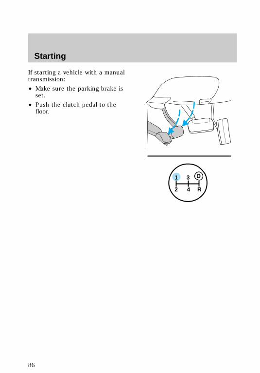
If starting a vehicle with a manualtransmission:
• Make sure the parking brake isset.
• Push the clutch pedal to thefloor.
1
2 4 R
3 D
Starting
86
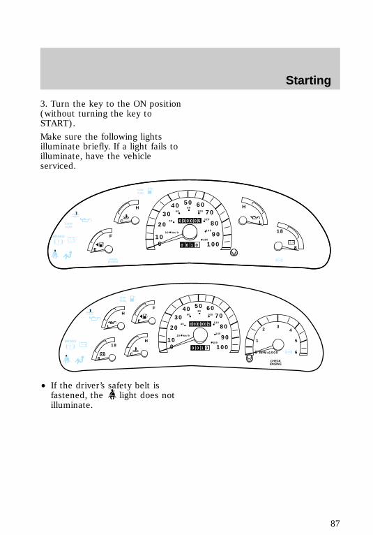
3. Turn the key to the ON position(without turning the key toSTART).
Make sure the following lightsilluminate briefly. If a light fails toilluminate, have the vehicleserviced.
• If the driver’s safety belt isfastened, the light does notilluminate.
! MPH
10
50
30 7040
80
120
140
180
40
20
0 100
90
60
80
60 100
20 km/h
0 0 1 0
000005C
H
E
F
DOORAJAR
LOWFUEL
MPH
CHECKENGINE
ABS
L
H
18
8
BRAKE
!
LOWFUEL
ABS
BRAKE
3
MPH
10
50
30 7040
80
120
140
180
40
20
0 100
90
60
80
60 100
20 km/h
0 0 1 0
0000052 4
5
60
1
L
H
C
H
E
F
8
18
RPMx1000
CHECKENGINE
Starting
87
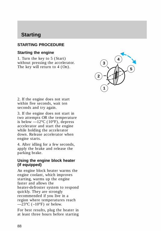
STARTING PROCEDURE
Starting the engine1. Turn the key to 5 (Start)without pressing the accelerator.The key will return to 4 (On).
2. If the engine does not startwithin five seconds, wait tenseconds and try again.
3. If the engine does not start intwo attempts OR the temperatureis below —12°C (10°F), depressaccelerator and start the enginewhile holding the acceleratordown. Release accelerator whenengine starts.
4. After idling for a few seconds,apply the brake and release theparking brake.
Using the engine block heater(if equipped)An engine block heater warms theengine coolant, which improvesstarting, warms up the enginefaster and allows theheater-defroster system to respondquickly. They are stronglyrecommended if you live in aregion where temperatures reach—23°C (–10°F) or below.
For best results, plug the heater inat least three hours before starting
3
2
1
5
4
com_starting_vehicle.01
com_engine_heater.01
Starting
88
the vehicle. Using the heater forlonger than three hours will notharm the engine, so the heater canbe plugged in the night beforestarting the vehicle.
To prevent electricalshock, do not use your
heater with ungroundedelectrical systems ortwo-pronged (cheater) adapters.
Guarding against exhaustfumesAlthough odorless and colorless,carbon monoxide is present inexhaust fumes. Take precautionsto avoid its dangerous effects.
If you ever smell exhaustfumes of any kind inside
your vehicle, have your dealerinspect and fix your vehicleimmediately. Do not drive if yousmell exhaust fumes. Thesefumes are harmful and could killyou.
Have the exhaust and bodyventilation systems checkedwhenever:
• the vehicle is raised for service
• the sound of the exhaust systemchanges
• the vehicle has been damaged ina collision
com_guarding_exhaust.01
com_ventilation_info.01
Starting
89
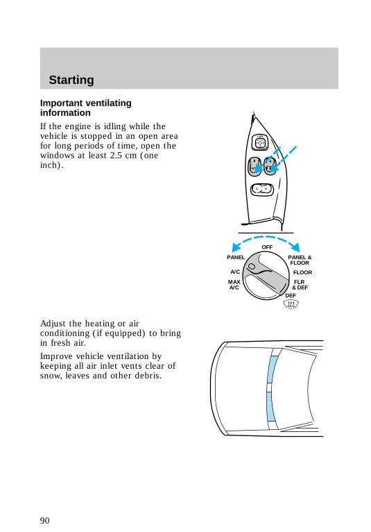
Important ventilatinginformationIf the engine is idling while thevehicle is stopped in an open areafor long periods of time, open thewindows at least 2.5 cm (oneinch).
Adjust the heating or airconditioning (if equipped) to bringin fresh air.
Improve vehicle ventilation bykeeping all air inlet vents clear ofsnow, leaves and other debris.
FLR & DEF
MAXA/C
FLOOR
PANEL &FLOOR
DEF
OFF
PANEL
A/C
L U
AUTO
L R
Starting
90
BRAKES
Rear anti-lock brake system(ABS) (if equipped)This system prevents one or bothrear wheels from locking up whenthe brakes are applied during asudden stop.
Even with rear ABS, the frontbrakes may lock up on any surface.Be careful when braking, especiallyon loose snow or gravel.
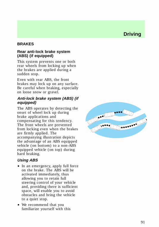
Anti-lock brake system (ABS) (ifequipped)The ABS operates by detecting theonset of wheel lock up duringbrake applications andcompensating for this tendency.The front wheels are preventedfrom locking even when the brakesare firmly applied. Theaccompanying illustration depictsthe advantage of an ABS equippedvehicle (on bottom) to a non-ABSequipped vehicle (on top) duringhard braking.
Using ABS• In an emergency, apply full forceon the brake. The ABS will beactivated immediately, thusallowing you to retain fullsteering control of your vehicleand, providing there is sufficientspace, will enable you to avoidobstacles and bring the vehicleto a quiet stop.
• We recommend that youfamiliarize yourself with this
f12_rear_abs
com_abs.01
com_using_abs.01
Driving
91

braking technique. However,avoid taking any unnecessaryrisks.
Parking brakeThe parking brake should be usedwhenever you park your vehicle. Itis not designed to stop a movingvehicle. However, if the normalbrakes fail, the parking brake canbe used to stop your vehicle in anemergency. Since the parkingbrake applies only the rear brakes,the vehicle’s stopping distance willincrease greatly and the handlingof your vehicle will be adverselyaffected.
Setting the parking brakeThe !
BRAKE light in the instrumentcluster will illuminate and remainilluminated (when the ignition
f12_parking_brake
f12_setting_pbrake
Driving
92
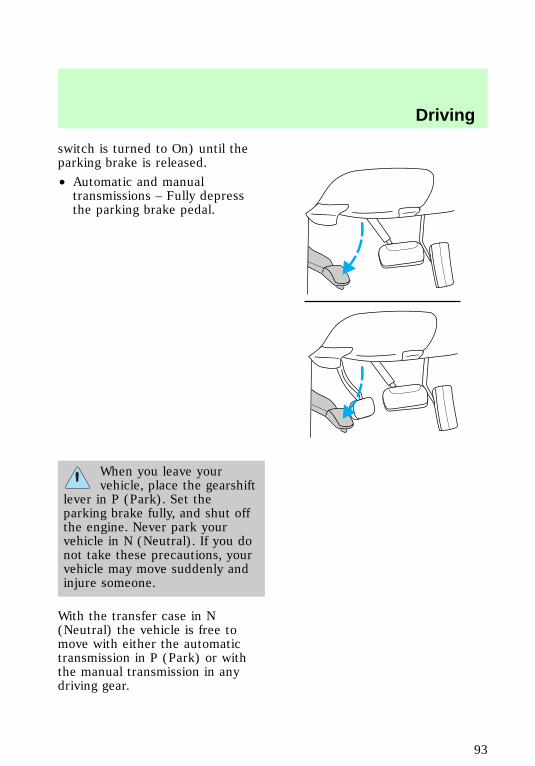
switch is turned to On) until theparking brake is released.
• Automatic and manualtransmissions – Fully depressthe parking brake pedal.
When you leave yourvehicle, place the gearshift
lever in P (Park). Set theparking brake fully, and shut offthe engine. Never park yourvehicle in N (Neutral). If you donot take these precautions, yourvehicle may move suddenly andinjure someone.
With the transfer case in N(Neutral) the vehicle is free tomove with either the automatictransmission in P (Park) or withthe manual transmission in anydriving gear.
Driving
93
Do not leave the vehicleunattended with the
transfer case in the N (Neutral)position. Always set the parkingbrake fully and turn off theignition when leaving the vehicle.
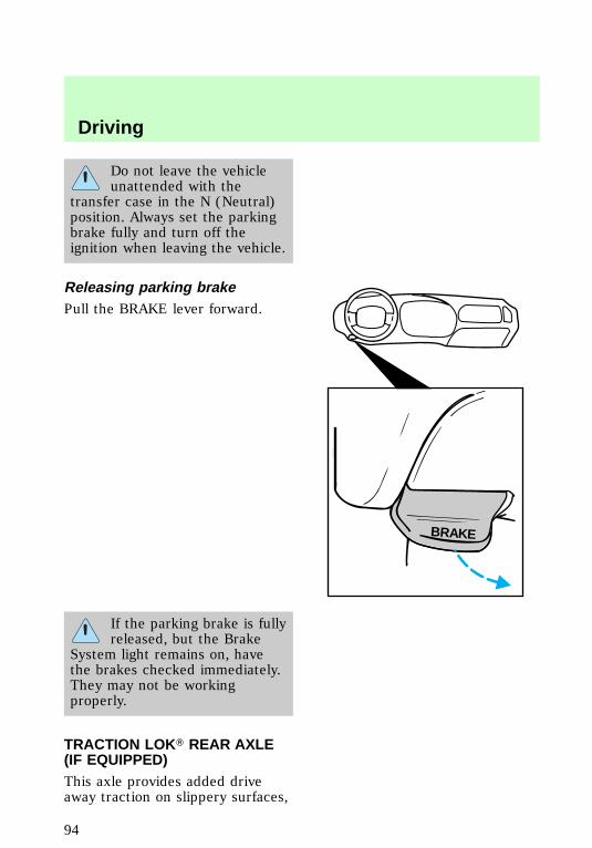
Releasing parking brakePull the BRAKE lever forward.
If the parking brake is fullyreleased, but the Brake
System light remains on, havethe brakes checked immediately.They may not be workingproperly.
TRACTION LOKT REAR AXLE(IF EQUIPPED)This axle provides added driveaway traction on slippery surfaces,
BRAKE
f12_releasing_pbrake
f12_traction_lok
Driving
94
particularly when one or morewheels are on a surface with poortraction.
AIR SUSPENSION (IFEQUIPPED)The air suspension system for therear wheels is designed to keepyour vehicle at a constant level byadding or releasing air from therear springs to compensate forincreases or decreases in vehicleload.
Normal vehicle operation does notrequire any action by the driver.
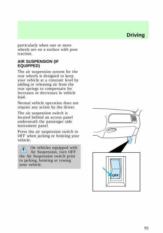
The air suspension switch islocated behind an access panelunderneath the passenger sideinstrument panel.
Press the air suspension switch toOFF when jacking or hoisting yourvehicle.
On vehicles equipped withAir Suspension, turn OFF
the Air Suspension switch priorto jacking, hoisting or towingyour vehicle.
OFF
f12_air_suspension
f12_transmission
Driving
95
TRANSMISSION OPERATION
Automatic transmissionoperation (if equipped)
Hold the brake pedal downwhile you move the
gearshift lever from position toposition. If you do not hold thebrake pedal down, your vehiclemay move unexpectedly andinjure someone.
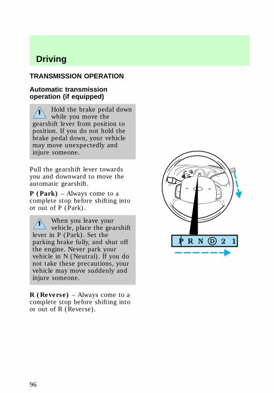
Pull the gearshift lever towardsyou and downward to move theautomatic gearshift.
P (Park) – Always come to acomplete stop before shifting intoor out of P (Park).
When you leave yourvehicle, place the gearshift
lever in P (Park). Set theparking brake fully, and shut offthe engine. Never park yourvehicle in N (Neutral). If you donot take these precautions, yourvehicle may move suddenly andinjure someone.
R (Reverse) – Always come to acomplete stop before shifting intoor out of R (Reverse).
f12_automatic
Driving
96
N (Neutral) – Vehicle is free toroll.
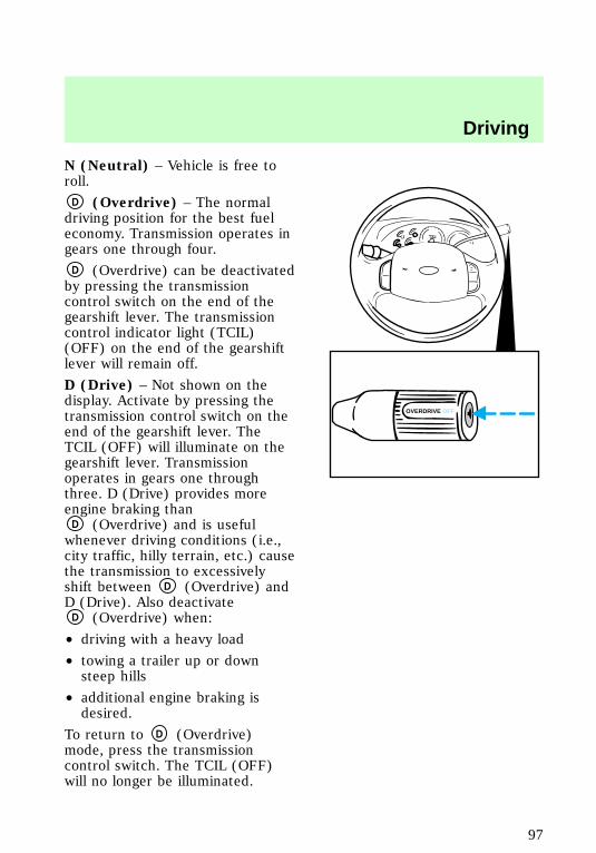
D (Overdrive) – The normaldriving position for the best fueleconomy. Transmission operates ingears one through four.
D (Overdrive) can be deactivatedby pressing the transmissioncontrol switch on the end of thegearshift lever. The transmissioncontrol indicator light (TCIL)(OFF) on the end of the gearshiftlever will remain off.
D (Drive) – Not shown on thedisplay. Activate by pressing thetransmission control switch on theend of the gearshift lever. TheTCIL (OFF) will illuminate on thegearshift lever. Transmissionoperates in gears one throughthree. D (Drive) provides moreengine braking than
D (Overdrive) and is usefulwhenever driving conditions (i.e.,city traffic, hilly terrain, etc.) causethe transmission to excessivelyshift between D (Overdrive) andD (Drive). Also deactivate
D (Overdrive) when:
• driving with a heavy load
• towing a trailer up or downsteep hills
• additional engine braking isdesired.
To return to D (Overdrive)mode, press the transmissioncontrol switch. The TCIL (OFF)will no longer be illuminated.
OVERDRIVE OFF
Driving
97
Each time the vehicle is started,the transmission will automaticallyreturn to normal overdrive mode.
2 (Second) – Use 2 (Second) tostart-up on slippery roads or toprovide additional engine brakingon downgrades. Transmissionoperates in first and second gears.
1 (Low) – Use 1 (Low) to providemaximum engine braking on steepdowngrades. Upshifts can be madeby shifting to 2 (Second) or to
D (Overdrive). Selecting 1 (Low)at higher speeds causes a shift to 2(Second), and will shift to 1 (Low)after vehicle decelerates to theproper speed.
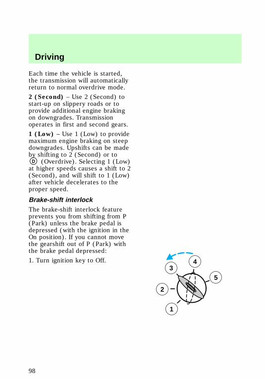
Brake-shift interlockThe brake-shift interlock featureprevents you from shifting from P(Park) unless the brake pedal isdepressed (with the ignition in theOn position). If you cannot movethe gearshift out of P (Park) withthe brake pedal depressed:
1. Turn ignition key to Off.3
2
1
5
4
f12_brake_shift_interlock
Driving
98
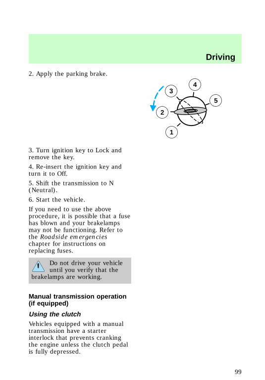
2. Apply the parking brake.
3. Turn ignition key to Lock andremove the key.
4. Re-insert the ignition key andturn it to Off.
5. Shift the transmission to N(Neutral).
6. Start the vehicle.
If you need to use the aboveprocedure, it is possible that a fusehas blown and your brakelampsmay not be functioning. Refer tothe Roadside emergencieschapter for instructions onreplacing fuses.
Do not drive your vehicleuntil you verify that the
brakelamps are working.
Manual transmission operation(if equipped)
Using the clutchVehicles equipped with a manualtransmission have a starterinterlock that prevents crankingthe engine unless the clutch pedalis fully depressed.
3
2
1
5
4
f12_manual
f12_using_clutch
Driving
99

When starting a vehicle with amanual transmission, you must:
1. Put gearshift in N (Neutral).
2. Hold down brake pedal.1
2 4 R
3 D
Driving
100
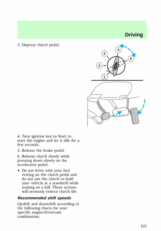
3. Depress clutch pedal.
4. Turn ignition key to Start tostart the engine and let it idle for afew seconds.
5. Release the brake pedal.
6. Release clutch slowly whilepressing down slowly on theaccelerator pedal.
• Do not drive with your footresting on the clutch pedal anddo not use the clutch to holdyour vehicle at a standstill whilewaiting on a hill. These actionswill seriously reduce clutch life.
Recommended shift speedsUpshift and downshift according tothe following charts for yourspecific engine/drivetraincombination:
34
5
2
1
f12_shift_speeds
Driving
101
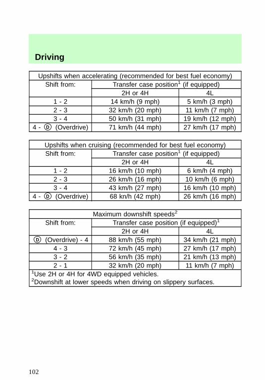
Upshifts when accelerating (recommended for best fuel economy)Shift from: Transfer case position1 (if equipped)
2H or 4H 4L1 - 2 14 km/h (9 mph) 5 km/h (3 mph)2 - 3 32 km/h (20 mph) 11 km/h (7 mph)3 - 4 50 km/h (31 mph) 19 km/h (12 mph)
4 - D (Overdrive) 71 km/h (44 mph) 27 km/h (17 mph)
Upshifts when cruising (recommended for best fuel economy)Shift from: Transfer case position1 (if equipped)
2H or 4H 4L1 - 2 16 km/h (10 mph) 6 km/h (4 mph)2 - 3 26 km/h (16 mph) 10 km/h (6 mph)3 - 4 43 km/h (27 mph) 16 km/h (10 mph)
4 - D (Overdrive) 68 kn/h (42 mph) 26 km/h (16 mph)
Maximum downshift speeds2
Shift from: Transfer case position (if equipped)1
2H or 4H 4LD (Overdrive) - 4 88 km/h (55 mph) 34 km/h (21 mph)
4 - 3 72 km/h (45 mph) 27 km/h (17 mph)3 - 2 56 km/h (35 mph) 21 km/h (13 mph)2 - 1 32 km/h (20 mph) 11 km/h (7 mph)
1Use 2H or 4H for 4WD equipped vehicles.2Downshift at lower speeds when driving on slippery surfaces.
Driving
102
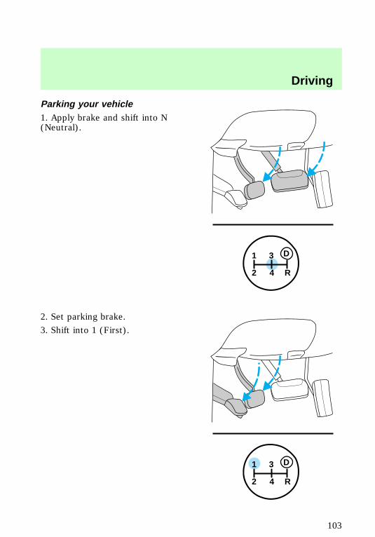
Parking your vehicle1. Apply brake and shift into N(Neutral).
2. Set parking brake.
3. Shift into 1 (First).
1
2 4 R
3 D
1
2 4 R
3 D
f12_parking
Driving
103
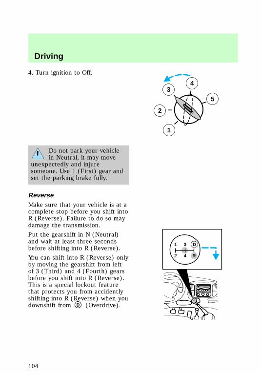
4. Turn ignition to Off.
Do not park your vehiclein Neutral, it may move
unexpectedly and injuresomeone. Use 1 (First) gear andset the parking brake fully.
ReverseMake sure that your vehicle is at acomplete stop before you shift intoR (Reverse). Failure to do so maydamage the transmission.
Put the gearshift in N (Neutral)and wait at least three secondsbefore shifting into R (Reverse).
You can shift into R (Reverse) onlyby moving the gearshift from leftof 3 (Third) and 4 (Fourth) gearsbefore you shift into R (Reverse).This is a special lockout featurethat protects you from accidentlyshifting into R (Reverse) when youdownshift from D (Overdrive).
3
2
1
5
4
1 3
2 4 R
D
f12_reverse
Driving
104
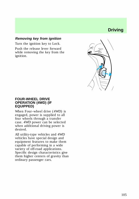
Removing key from ignitionTurn the ignition key to Lock.
Push the release lever forwardwhile removing the key from theignition.
FOUR-WHEEL DRIVEOPERATION (4WD) (IFEQUIPPED)When Four–wheel drive (4WD) isengaged, power is supplied to allfour wheels through a transfercase. 4WD power can be selectedwhen additional driving power isdesired.
All utility-type vehicles and 4WDvehicles have special design andequipment features to make themcapable of performing in a widevariety of off-road applications.Specific design characteristics givethem higher centers of gravity thanordinary passenger cars.
f12_four_wd
Driving
105
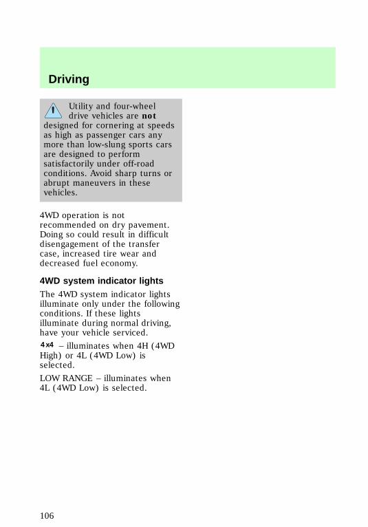
Utility and four-wheeldrive vehicles are not
designed for cornering at speedsas high as passenger cars anymore than low-slung sports carsare designed to performsatisfactorily under off-roadconditions. Avoid sharp turns orabrupt maneuvers in thesevehicles.
4WD operation is notrecommended on dry pavement.Doing so could result in difficultdisengagement of the transfercase, increased tire wear anddecreased fuel economy.
4WD system indicator lightsThe 4WD system indicator lightsilluminate only under the followingconditions. If these lightsilluminate during normal driving,have your vehicle serviced.4x4 – illuminates when 4H (4WDHigh) or 4L (4WD Low) isselected.
LOW RANGE – illuminates when4L (4WD Low) is selected.
f12_fourwd_lights
f12_using_4wd_leverop
Driving
106
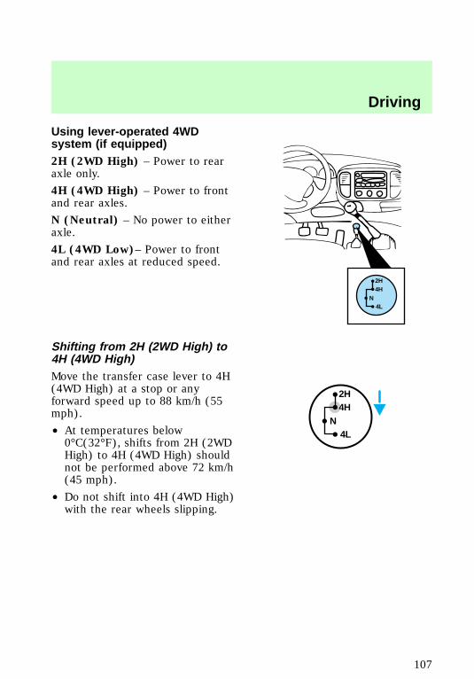
Using lever-operated 4WDsystem (if equipped)2H (2WD High) – Power to rearaxle only.
4H (4WD High) – Power to frontand rear axles.
N (Neutral) – No power to eitheraxle.
4L (4WD Low)– Power to frontand rear axles at reduced speed.
Shifting from 2H (2WD High) to4H (4WD High)Move the transfer case lever to 4H(4WD High) at a stop or anyforward speed up to 88 km/h (55mph).
• At temperatures below0°C(32°F), shifts from 2H (2WDHigh) to 4H (4WD High) shouldnot be performed above 72 km/h(45 mph).
• Do not shift into 4H (4WD High)with the rear wheels slipping.
2H4H
4LN
2H4H
4LN
f12_shifting_2h_4h
f12_shifting_4h_2h
Driving
107
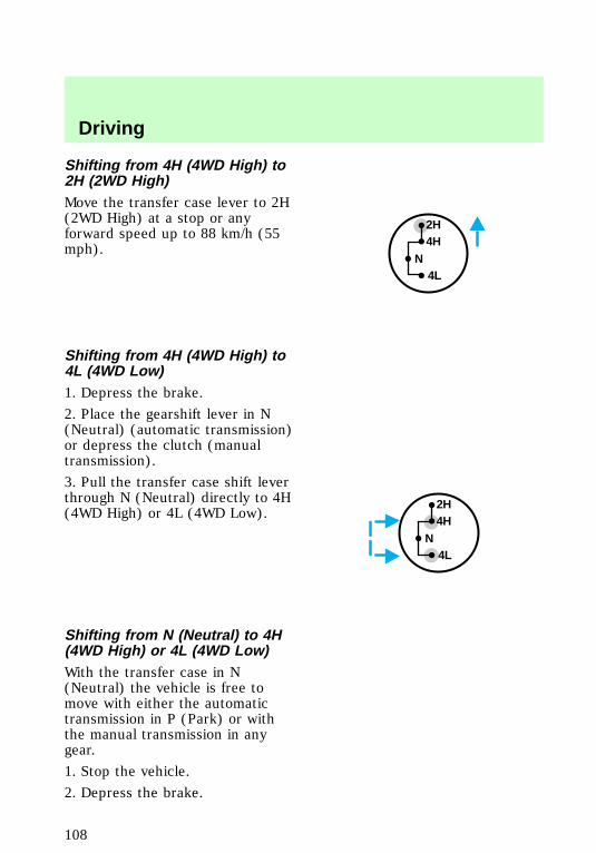
Shifting from 4H (4WD High) to2H (2WD High)Move the transfer case lever to 2H(2WD High) at a stop or anyforward speed up to 88 km/h (55mph).
Shifting from 4H (4WD High) to4L (4WD Low)1. Depress the brake.
2. Place the gearshift lever in N(Neutral) (automatic transmission)or depress the clutch (manualtransmission).
3. Pull the transfer case shift leverthrough N (Neutral) directly to 4H(4WD High) or 4L (4WD Low).
Shifting from N (Neutral) to 4H(4WD High) or 4L (4WD Low)With the transfer case in N(Neutral) the vehicle is free tomove with either the automatictransmission in P (Park) or withthe manual transmission in anygear.
1. Stop the vehicle.
2. Depress the brake.
2H4H
4LN
2H4H
4LN
f12_shifting_4h_4l
f12_shift_n_4h4l
Driving
108
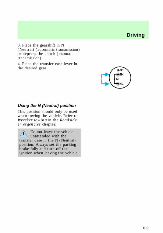
3. Place the gearshift in N(Neutral) (automatic transmission)or depress the clutch (manualtransmission).
4. Place the transfer case lever inthe desired gear.
Using the N (Neutral) positionThis position should only be usedwhen towing the vehicle. Refer toWrecker towing in the Roadsideemergencies chapter.
Do not leave the vehicleunattended with the
transfer case in the N (Neutral)position. Always set the parkingbrake fully and turn off theignition when leaving the vehicle.
2H4H
4LN
f12_neutral_tcase
f12_control_trac
Driving
109
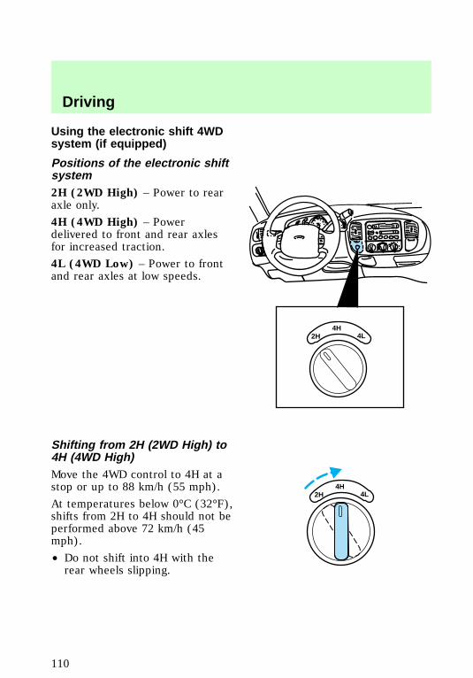
Using the electronic shift 4WDsystem (if equipped)
Positions of the electronic shiftsystem2H (2WD High) – Power to rearaxle only.
4H (4WD High) – Powerdelivered to front and rear axlesfor increased traction.
4L (4WD Low) – Power to frontand rear axles at low speeds.
Shifting from 2H (2WD High) to4H (4WD High)Move the 4WD control to 4H at astop or up to 88 km/h (55 mph).
At temperatures below 0°C (32°F),shifts from 2H to 4H should not beperformed above 72 km/h (45mph).
• Do not shift into 4H with therear wheels slipping.
2H4H
4L
2H4H
4L
f12_ct_2h_4h
f12_ct_4h_2h
Driving
110

Shifting from 4H (4WD high) to2H (2WD high)Move the 4WD control to 2H atany forward speed.
Shifting between 4H (4WD high)and 4L (4WD low)1. Bring the vehicle to a stop.
2. Depress the brake.
3. Place the gearshift in N(Neutral) (automatic transmission)or depress the clutch (manualtransmission).
4. Move the 4WD control to the 4Hor 4L position.
Driving off-road with 4WDYour vehicle is specially equippedfor driving on sand, snow, mud andrough terrain and has operatingcharacteristics that are somewhatdifferent from conventionalvehicles, both on and off the road.The following information will helpyou learn to properly use 4WD.
2H4H
4L
2H4H
4L
f12_ct_4h_4l
f12_driving_offroad
Driving
111
When using 4WD, maintainsteering wheel control at all times,especially in rough terrain. Sincesudden changes in terrain canresult in abrupt steering wheelmotion, make sure you grip thesteering wheel from the outside.Do not grip the spokes.
Drive cautiously to avoid vehicledamage from concealed objectssuch as rocks and stumps.
You should either know the terrainor examine maps of the areabefore driving. Map out your routebefore driving in the area. Formore information on drivingoff-road, read the “Four Wheeling”supplement in your owner’sportfolio.
If your vehicle gets stuckIf the vehicle is stuck, shift thetransmission in a steady motionbetween forward and reversegears. Allow the transmission toengage, then press lightly on theaccelerator. DO NOT rock thevehicle for more than a fewminutes. The transmission andtires may be damaged or theengine can overheat.
Do not spin the wheels atover 35 mph (55 km/h).
The tires may fail and injure apassenger or bystander.
SandWhen driving over sand, try tokeep all four wheels on the most
f12_driving_sand
Driving
112
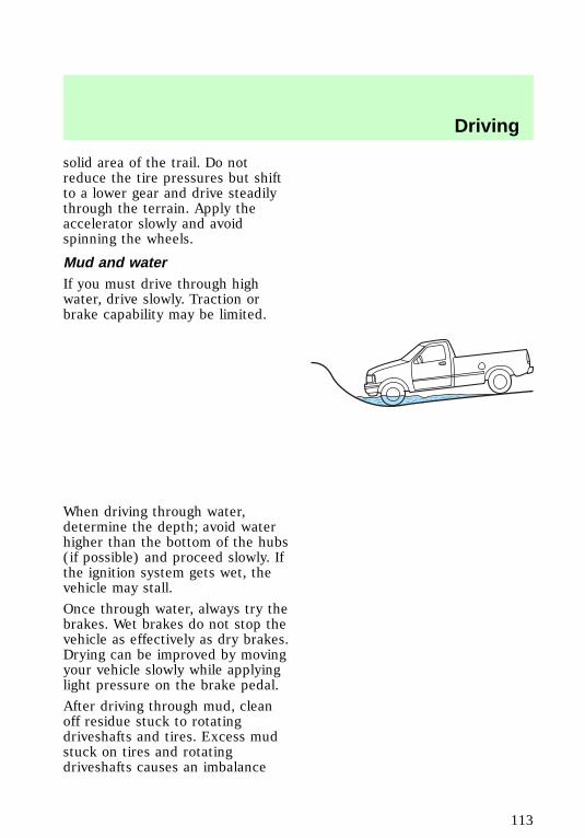
solid area of the trail. Do notreduce the tire pressures but shiftto a lower gear and drive steadilythrough the terrain. Apply theaccelerator slowly and avoidspinning the wheels.
Mud and waterIf you must drive through highwater, drive slowly. Traction orbrake capability may be limited.
When driving through water,determine the depth; avoid waterhigher than the bottom of the hubs(if possible) and proceed slowly. Ifthe ignition system gets wet, thevehicle may stall.
Once through water, always try thebrakes. Wet brakes do not stop thevehicle as effectively as dry brakes.Drying can be improved by movingyour vehicle slowly while applyinglight pressure on the brake pedal.
After driving through mud, cleanoff residue stuck to rotatingdriveshafts and tires. Excess mudstuck on tires and rotatingdriveshafts causes an imbalance
f12_driving_mud_water
Driving
113

that could damage drivecomponents.
If the transmission and transfercase are submerged in water, theirfluids should be checked andchanged, if necessary.
If the rear axle is submerged inwater, the rear axle lubricantshould be checked and changed, ifnecessary. The rear axle is filledwith a synthetic lubricant and doesnot normally require a lubricantchange for the life of the vehicle.Rear axle lubricant quantitiesshould not need to be checkedunless a leak is suspected.
Driving on hill or slope terrainWhen driving on a hill, avoiddriving crosswise or turning onsteep slopes. You could losetraction and slip sideways. Drivestraight up, straight down or avoidthe hill completely. Know theconditions on the other side of ahill before driving over the crest.
When climbing a steep hill, start ina lower gear rather thandownshifting to a lower gear froma higher gear once the ascent hasstarted. This reduces strain on theengine and the possibility ofstalling.
f12_driving_hill
Driving
114
When descending a steep hill,avoid sudden braking. Rapidpumping of the brake pedal willhelp slow the vehicle and stillmaintain steering control.
When speed control is on and youare driving uphill, your vehiclespeed may drop considerably,especially if you are carrying aheavy load.
If vehicle speed drops more than15–25 km/h (8–14 mph), the speedcontrol will cancel automatically.Resume speed with acceleratorpedal.
If speed control cancels afterclimbing the hill, reset speed bypressing and holding the SETACCEL button (to resume speedsover 50 km/h (30 mph).
Automatic transmission may shiftfrequently while driving up steepgrades. Eliminate frequent shiftingby shifting out of D (Overdrive)into D (Drive).
Driving on snow and iceA 4WD vehicle has advantagesover 2WD vehicles in snow and icebut can skid like any other vehicle.
Avoid sudden applications ofpower and quick changes ofdirection on snow and ice. Applythe accelerator slowly and steadilywhen starting from a full stop.
When braking, apply the brakes asyou normally would. In order toallow the anti-lock brake system(ABS) to operate properly, keep
f12_driving_snow_ice
Driving
115
steady pressure on the brakepedal.
Allow more stopping distance anddrive slower than usual. Considerusing one of the lower gears.
VEHICLE LOADING
It is extremely dangerousto ride in a cargo area,
inside or outside of a vehicle. Ina collision, people riding in theseareas are more likely to beseriously injured or killed. Do notallow people to ride in any areaof your vehicle that is notequipped with seats and safetybelts. Be sure everyone in yourvehicle is in a seat and using asafety belt properly.
Before loading a vehicle, familiarizeyourself with the following terms:
• Base Curb Weight: Weight ofthe vehicle including anystandard equipment, fluids,lubricants, etc. It does notinclude passengers oraftermarket equipment.
• Payload: Combined maximumallowable weight of cargo,passengers and optionalequipment. The payload equalsgross vehicle weight rating(GVWR) minus base curbweight.
• Gross vehicle weight (GVW):Base curb weight plus thepayload weight (includingpassengers, cargo and optional
f12_heavy_load
Driving
116
equipment. Remember, the GVWis not a limit or a specification.
• Gross vehicle weight rating(GVWR): Maximum total weightof the base vehicle, passengers,optional equipment and cargo.The GVWR is specific to eachparticular vehicle and is listedon the Safety ComplianceCertification Label on the driverdoor pillar.
• Gross axle weight rating(GAWR): Carrying capacity foreach axle system (front andrear). This amount is specific toeach particular vehicle and islisted on the Safety ComplianceCertification Label on the driverdoor pillar.
• Gross combined weightrating (GCWR): Maximumcombined weight of the towingvehicle (including passengersand cargo) and the trailer. TheGCWR indicates the maximumloaded weight that the vehicle isallowed to tow.
• Maximum trailer weight:Maximum weight of a trailer theloaded vehicle (includingpassengers and cargo) ispermitted to tow. It isdetermined by subtracting theweight of the loaded towingvehicle from the GCWR of thetowing vehicle.
• Trailer weight range:Specified weight range that thetrailer must fall within that
Driving
117
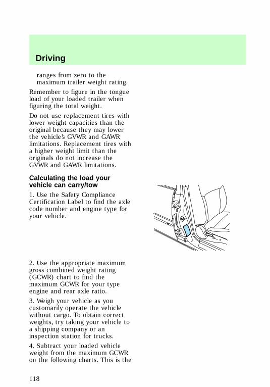
ranges from zero to themaximum trailer weight rating.
Remember to figure in the tongueload of your loaded trailer whenfiguring the total weight.
Do not use replacement tires withlower weight capacities than theoriginal because they may lowerthe vehicle’s GVWR and GAWRlimitations. Replacement tires witha higher weight limit than theoriginals do not increase theGVWR and GAWR limitations.
Calculating the load yourvehicle can carry/tow1. Use the Safety ComplianceCertification Label to find the axlecode number and engine type foryour vehicle.
2. Use the appropriate maximumgross combined weight rating(GCWR) chart to find themaximum GCWR for your typeengine and rear axle ratio.
3. Weigh your vehicle as youcustomarily operate the vehiclewithout cargo. To obtain correctweights, try taking your vehicle toa shipping company or aninspection station for trucks.
4. Subtract your loaded vehicleweight from the maximum GCWRon the following charts. This is the
f12_calculating_load
Driving
118
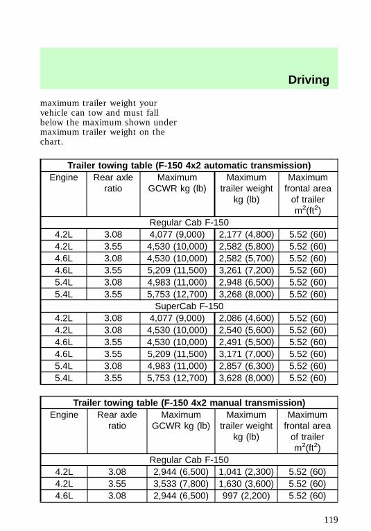
maximum trailer weight yourvehicle can tow and must fallbelow the maximum shown undermaximum trailer weight on thechart.
Trailer towing table (F-150 4x2 automatic transmission)Engine Rear axle
ratioMaximum
GCWR kg (lb)Maximum
trailer weightkg (lb)
Maximumfrontal areaof trailerm2(ft2)
Regular Cab F-1504.2L 3.08 4,077 (9,000) 2,177 (4,800) 5.52 (60)4.2L 3.55 4,530 (10,000) 2,582 (5,800) 5.52 (60)4.6L 3.08 4,530 (10,000) 2,582 (5,700) 5.52 (60)4.6L 3.55 5,209 (11,500) 3,261 (7,200) 5.52 (60)5.4L 3.08 4,983 (11,000) 2,948 (6,500) 5.52 (60)5.4L 3.55 5,753 (12,700) 3,268 (8,000) 5.52 (60)
SuperCab F-1504.2L 3.08 4,077 (9,000) 2,086 (4,600) 5.52 (60)4.2L 3.08 4,530 (10,000) 2,540 (5,600) 5.52 (60)4.6L 3.55 4,530 (10,000) 2,491 (5,500) 5.52 (60)4.6L 3.55 5,209 (11,500) 3,171 (7,000) 5.52 (60)5.4L 3.08 4,983 (11,000) 2,857 (6,300) 5.52 (60)5.4L 3.55 5,753 (12,700) 3,628 (8,000) 5.52 (60)
Trailer towing table (F-150 4x2 manual transmission)Engine Rear axle
ratioMaximum
GCWR kg (lb)Maximum
trailer weightkg (lb)
Maximumfrontal areaof trailerm2(ft2)
Regular Cab F-1504.2L 3.08 2,944 (6,500) 1,041 (2,300) 5.52 (60)4.2L 3.55 3,533 (7,800) 1,630 (3,600) 5.52 (60)4.6L 3.08 2,944 (6,500) 997 (2,200) 5.52 (60)
Driving
119
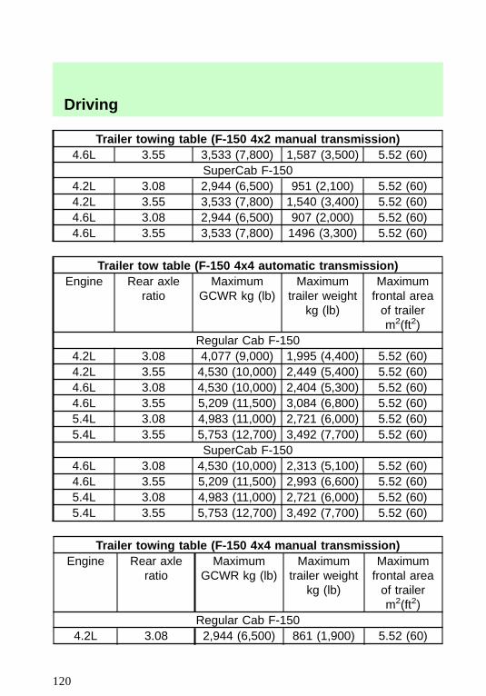
Trailer towing table (F-150 4x2 manual transmission)4.6L 3.55 3,533 (7,800) 1,587 (3,500) 5.52 (60)
SuperCab F-1504.2L 3.08 2,944 (6,500) 951 (2,100) 5.52 (60)4.2L 3.55 3,533 (7,800) 1,540 (3,400) 5.52 (60)4.6L 3.08 2,944 (6,500) 907 (2,000) 5.52 (60)4.6L 3.55 3,533 (7,800) 1496 (3,300) 5.52 (60)
Trailer tow table (F-150 4x4 automatic transmission)Engine Rear axle
ratioMaximum
GCWR kg (lb)Maximum
trailer weightkg (lb)
Maximumfrontal areaof trailerm2(ft2)
Regular Cab F-1504.2L 3.08 4,077 (9,000) 1,995 (4,400) 5.52 (60)4.2L 3.55 4,530 (10,000) 2,449 (5,400) 5.52 (60)4.6L 3.08 4,530 (10,000) 2,404 (5,300) 5.52 (60)4.6L 3.55 5,209 (11,500) 3,084 (6,800) 5.52 (60)5.4L 3.08 4,983 (11,000) 2,721 (6,000) 5.52 (60)5.4L 3.55 5,753 (12,700) 3,492 (7,700) 5.52 (60)
SuperCab F-1504.6L 3.08 4,530 (10,000) 2,313 (5,100) 5.52 (60)4.6L 3.55 5,209 (11,500) 2,993 (6,600) 5.52 (60)5.4L 3.08 4,983 (11,000) 2,721 (6,000) 5.52 (60)5.4L 3.55 5,753 (12,700) 3,492 (7,700) 5.52 (60)
Trailer towing table (F-150 4x4 manual transmission)Engine Rear axle
ratioMaximum
GCWR kg (lb)Maximum
trailer weightkg (lb)
Maximumfrontal areaof trailerm2(ft2)
Regular Cab F-1504.2L 3.08 2,944 (6,500) 861 (1,900) 5.52 (60)
Driving
120
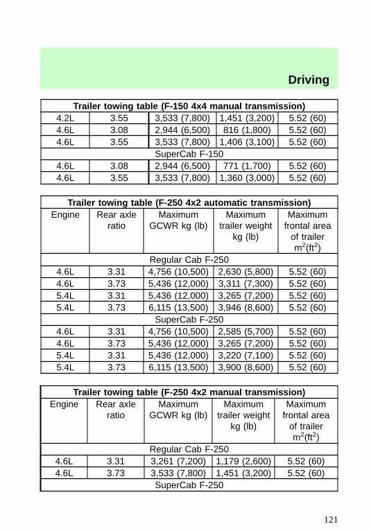
Trailer towing table (F-150 4x4 manual transmission)4.2L 3.55 3,533 (7,800) 1,451 (3,200) 5.52 (60)4.6L 3.08 2,944 (6,500) 816 (1,800) 5.52 (60)4.6L 3.55 3,533 (7,800) 1,406 (3,100) 5.52 (60)
SuperCab F-1504.6L 3.08 2,944 (6,500) 771 (1,700) 5.52 (60)4.6L 3.55 3,533 (7,800) 1,360 (3,000) 5.52 (60)
Trailer towing table (F-250 4x2 automatic transmission)Engine Rear axle
ratioMaximum
GCWR kg (lb)Maximum
trailer weightkg (lb)
Maximumfrontal areaof trailerm2(ft2)
Regular Cab F-2504.6L 3.31 4,756 (10,500) 2,630 (5,800) 5.52 (60)4.6L 3.73 5,436 (12,000) 3,311 (7,300) 5.52 (60)5.4L 3.31 5,436 (12,000) 3,265 (7,200) 5.52 (60)5.4L 3.73 6,115 (13,500) 3,946 (8,600) 5.52 (60)
SuperCab F-2504.6L 3.31 4,756 (10,500) 2,585 (5,700) 5.52 (60)4.6L 3.73 5,436 (12,000) 3,265 (7,200) 5.52 (60)5.4L 3.31 5,436 (12,000) 3,220 (7,100) 5.52 (60)5.4L 3.73 6,115 (13,500) 3,900 (8,600) 5.52 (60)
Trailer towing table (F-250 4x2 manual transmission)Engine Rear axle
ratioMaximum
GCWR kg (lb)Maximum
trailer weightkg (lb)
Maximumfrontal areaof trailerm2(ft2)
Regular Cab F-2504.6L 3.31 3,261 (7,200) 1,179 (2,600) 5.52 (60)4.6L 3.73 3,533 (7,800) 1,451 (3,200) 5.52 (60)
SuperCab F-250
Driving
121
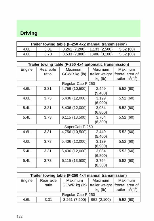
Trailer towing table (F-250 4x2 manual transmission)4.6L 3.31 3,261 (7,200) 1,133 (2,500) 5.52 (60)4.6L 3.73 3,533 (7,800) 1,406 (3,100) 5.52 (60)
Trailer towing table (F-250 4x4 automatic transmission)Engine Rear axle
ratioMaximum
GCWR kg (lb)Maximum
trailer weightkg (lb)
Maximumfrontal area oftrailer m2(ft2)
Regular Cab F-2504.6L 3.31 4,756 (10,500) 2,449
(5,400)5.52 (60)
4.6L 3.73 5,436 (12,000) 3,129(6,900)
5.52 (60)
5.4L 3.31 5,436 (12,000) 3,084(6,800)
5.52 (60)
5.4L 3.73 6,115 (13,500) 3,764(8,300)
5.52 (60)
SuperCab F-2504.6L 3.31 4,756 (10,500) 2,449
(5,400)5.52 (60)
4.6L 3.73 5,436 (12,000) 3,129(6,900)
5.52 (60)
5.4L 3.31 5,436 (12,000) 3,084(6,800)
5.52 (60)
5.4L 3.73 6,115 (13,500) 3,764(8,300)
5.52 (60)
Trailer towing table (F-250 4x4 manual transmission)Engine Rear axle
ratioMaximum
GCWR kg (lb)Maximum
trailer weightkg (lb)
Maximumfrontal area oftrailer m2(ft2)
Regular Cab F-2504.6L 3.31 3,261 (7,200) 952 (2,100) 5.52 (60)
Driving
122
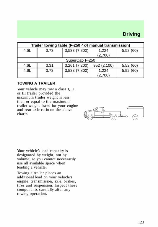
Trailer towing table (F-250 4x4 manual transmission)4.6L 3.73 3,533 (7,800) 1,224
(2,700)5.52 (60)
SuperCab F-2504.6L 3.31 3,261 (7,200) 952 (2,100) 5.52 (60)4.6L 3.73 3,533 (7,800) 1,224
(2,700)5.52 (60)
TOWING A TRAILERYour vehicle may tow a class I, IIor III trailer provided themaximum trailer weight is lessthan or equal to the maximumtrailer weight listed for your engineand rear axle ratio on the abovecharts.
Your vehicle’s load capacity isdesignated by weight, not byvolume, so you cannot necessarilyuse all available space whenloading a vehicle.
Towing a trailer places anadditional load on your vehicle’sengine, transmission, axle, brakes,tires and suspension. Inspect thesecomponents carefully after anytowing operation.
f12_trailer
Driving
123
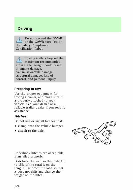
Do not exceed the GVWRor the GAWR specified on
the Safety ComplianceCertification Label.
Towing trailers beyond themaximum recommended
gross trailer weight could resultin engine damage,transmission/axle damage,structural damage, loss ofcontrol, and personal injury.
Preparing to towUse the proper equipment fortowing a trailer, and make sure itis properly attached to yourvehicle. See your dealer or areliable trailer dealer if you requireassistance.
HitchesDo not use or install hitches that:
• clamp onto the vehicle bumper
• attach to the axle.
Underbody hitches are acceptableif installed properly.
Distribute the load so that only 10to 15% of the total is on thetongue. Tie down the load so thatit does not shift and change theweight on the hitch.
f12_preparing_tow
f12_hitches
Driving
124
Using a load-equalizing hitchWhen hooking up a trailer using aload-equalizing hitch, always usethe following procedure.
1. Park the unloaded vehicle on alevel surface. With the ignition onand all doors closed, allow thevehicle to stand for severalminutes so that it can level.
2. Turn the air suspension switchto OFF (if equipped).
3. Measure the height of areference point on the front andrear bumpers at the center of thevehicle.
4. Attach the trailer to the vehicleand adjust the hitch equalizers sothat the front bumper height is0–13 mm (0.5 in). After properadjustment, the rear bumpershould be no higher than in step 3.
5. Turn on the air suspensionswitch.
Adjusting an equalizinghitch so the rear bumper
of the vehicle is lower or higherthan it was unloaded will defeatthe function of the loadequalizing hitch and may causeunpredictable handling.
Step bumper (if equipped)Step bumpers have a built-in hitchand only require a ball with a 2.5cm (1 in.) shank diameter. Stepbumpers have a Class III capability(2,270 kg [5,000 lb] trailer weightand 91 kg [200 lb] tongue weight.
f12_step_bumper
Driving
125
If it is necessary to relocate thetrailer hitch ball position, aframe-mounted trailer hitch mustbe installed.
Safety chainsAlways use safety chains betweenyour vehicle and trailer. Crosschains under the trailer tongue andallow slack for turning corners.Connect safety chains to thevehicle frame or hook retainers.Never attach chains to the bumper.
Trailer brakesTrailer brakes are required onmost towed vehicles weighing over680 kg (1,500 lbs).
Do not connect a trailer’shydraulic brake system
directly to your vehicle’s brakesystem. Your vehicle may nothave enough braking power andyour chances of having acollision greatly increase.
Trailer lampsTrailer lamps are required on mosttowed vehicles. Make sure yourtrailer lamps conform to Federaland local regulations. See yourdealer or trailer rental agency forthe proper instructions andequipment for hooking up trailerlamps.
Driving while you towDo not drive faster than 88 km/h(55 mph) while towing a trailer. Donot drive faster than 72 km/h (45
f12_safety_chains
f12_trailer_brakes
f12_trailer_lamps
f12_driving_towing
Driving
126
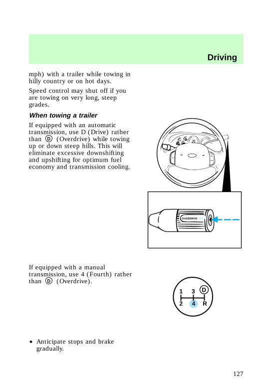
mph) with a trailer while towing inhilly country or on hot days.
Speed control may shut off if youare towing on very long, steepgrades.
When towing a trailerIf equipped with an automatictransmission, use D (Drive) ratherthan D (Overdrive) while towingup or down steep hills. This willeliminate excessive downshiftingand upshifting for optimum fueleconomy and transmission cooling.
If equipped with a manualtransmission, use 4 (Fourth) ratherthan D (Overdrive).
• Anticipate stops and brakegradually.
OVERDRIVE OFF
1
2 4 R
3 D
f12_when_you_tow
Driving
127
• Allow more room for stoppingwith a trailer attached.
• Practice turning, stopping andbacking in an area beforestarting on a trip to get the feelof the vehicle/trailercombination.
• When turning, drive slightlybeyond the normal turning pointso the trailer wheels will clearcurbs and other obstacles.
• When stopped in traffic for longperiods of time in hot weather,place the automatic transmissiongearshift in P (Park) to increaseidle speed. This aids enginecooling and air conditionerefficiency.
• Vehicles with trailers should notbe parked on a grade. If youmust park on a grade, placewheel chocks under the trailer’swheels.
• After you have travelled about80 km (50 miles), thoroughlycheck your hitch, electricalconnections and trailer wheellug nuts.
Launching or retrieving a boatWhen backing down a ramp duringboat launching or retrieval,
• Do not allow the static waterlevel to rise above the bottomedge of the rear bumper and
• Do not allow waves to breakhigher than 15 cm (six inches)above the bottom edge of therear bumper.
com_launch-retrieving_boat.01
Driving
128
Exceeding these limits may allowwater to enter critical vehiclecomponents, adversely affectingdriveability, emissions andreliability.
Servicing when towingIf you tow a trailer for longdistances, your vehicle will requiremore frequent service intervals.Refer to the “Service Guide” formore information.
SNOWPLOWINGFord recommends the followingspecifications for low speed,personal use snow removal:
• F-150 4WD long wheelbase orF-250 4WD Regular Cab
• 4.6L or 5.4L engine
• Super engine cooling
• Heavy duty front suspensionpackage
• Automatic transmission withauxiliary automatic transmissionfluid cooling
• All-terrain tires
Do not install a snowplow andplow with your vehicle until it hasbeen driven at least 800 km (500miles).
Installing snowplowRead the following instructionsbefore installing a snowplow:
• Front GAWR must not exceed63% of the GVW. Add ballastweight to the back of the
f12_service_towing
f12_snowplowing
f12_install_plow
Driving
129
vehicle, if necessary. Refer tothe Safety ComplianceCertification Label to find FrontGAWR.
• The Front Axle AccessoryReserve Capacity and the TotalAccessory Reserve Capacitylisted on the bottom right of theSafety Compliance CertificationLabel will determine whether ornot the addition of a snowplowwill overload your vehicle.
• The weight of the snowplow andsupporting componentsdistributed to the front axlemust not exceed the frontaccessory reserve capacity.
• The total weight of thesnowplow and aftermarketequipment must not exceed theTotal Accessory ReserveCapacity.
• The weight of the installedsnowplow and aftermarketequipment must not load thevehicle beyond the GAWR andGVWR listed on the SafetyCompliance Certification Label.
• Federal and most localregulations require additionalexterior lamps forsnowplow-equipped vehicles.Consult your dealer foradditional information.
• After installing a snowplow tothe vehicle, ensure the vehicle’sfront toe alignment and frontride height are withinspecification (reset if required).
Driving
130
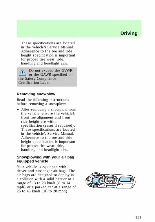
These specifications are locatedin the vehicle’s Service Manual.Adherence to the toe and rideheight specification is importantfor proper tire wear, ride,handling and headlight aim.
Do not exceed the GVWRor the GAWR specified on
the Safety ComplianceCertification Label.
Removing snowplowRead the following instructionsbefore removing a snowplow:
• After removing a snowplow fromthe vehicle, ensure the vehicle’sfront toe alignment and frontride height are withinspecification (reset if required).These specifications are locatedin the vehicle’s Service Manual.Adherence to the toe and rideheight specification is importantfor proper tire wear, ride,handling and headlight aim.
Snowplowing with your air bagequipped vehicleYour vehicle is equipped withdriver and passenger air bags. Theair bags are designed to deploy ina collision with a solid barrier at arange of 13 to 23 km/h (8 to 14mph) or a parked car at a range of25 to 45 km/h (16 to 28 mph).
f12_remove
f12_snowplow_srs
Driving
131
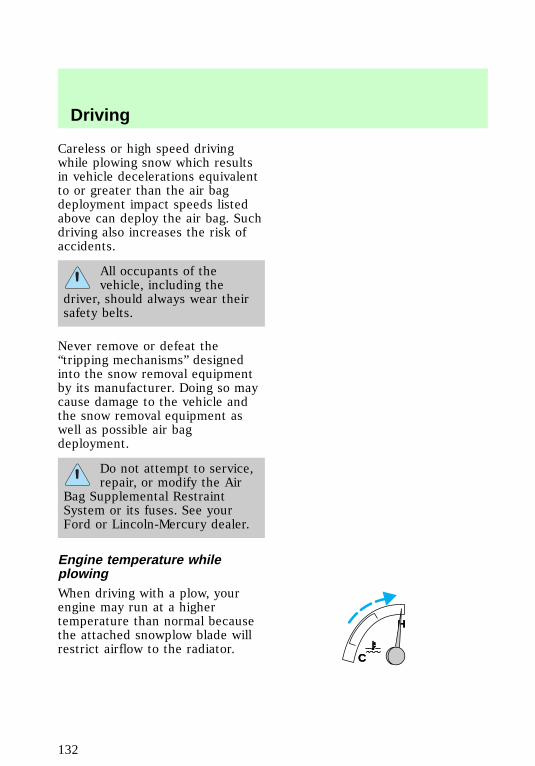
Careless or high speed drivingwhile plowing snow which resultsin vehicle decelerations equivalentto or greater than the air bagdeployment impact speeds listedabove can deploy the air bag. Suchdriving also increases the risk ofaccidents.
All occupants of thevehicle, including the
driver, should always wear theirsafety belts.
Never remove or defeat the“tripping mechanisms” designedinto the snow removal equipmentby its manufacturer. Doing so maycause damage to the vehicle andthe snow removal equipment aswell as possible air bagdeployment.
Do not attempt to service,repair, or modify the Air
Bag Supplemental RestraintSystem or its fuses. See yourFord or Lincoln-Mercury dealer.
Engine temperature whileplowingWhen driving with a plow, yourengine may run at a highertemperature than normal becausethe attached snowplow blade willrestrict airflow to the radiator.
C
H
C
H
f12_driving_wplow
Driving
132
If you are driving more then 24 km(15 miles) at temperatures abovefreezing, angle the plow bladeeither full left or full right toprovide maximum airflow to theradiator.
If you are driving less than 24 km(15 miles) at speeds up to 64 km/h(40 mph) in cold weather, you willnot need to worry about bladeposition to provide maximumairflow.
Transmission operation whileplowing• Shift transfer case to 4L (4WDLow) when plowing in smallareas at speeds below 8 km/h (5mph).
• Shift transfer case to 4H (4WDHigh) when plowing larger areasor light snow at higher speeds.Do not exceed 24 km/h (15mph).
• Do not shift the transmissionfrom a forward gear to R(Reverse) until the engine is atidle and the wheels are stopped.
• If the vehicle is stuck, shift thetransmission in a steady motionbetween forward and reversegears. Do not rock the vehiclefor more than a few minutes.The transmission and tires maybe damaged or the engine canoverheat.
Driving
133
Do not spin the wheels atover 35 mph (55 km/h).
The tires may fail and injure apassenger or bystander.
FUEL CONSUMPTIONFuel economy can be improved byavoiding:
• lack of regular, scheduledmaintenance
• excessive speed
• rapid acceleration.
f12_fuel_consumption
Driving
134
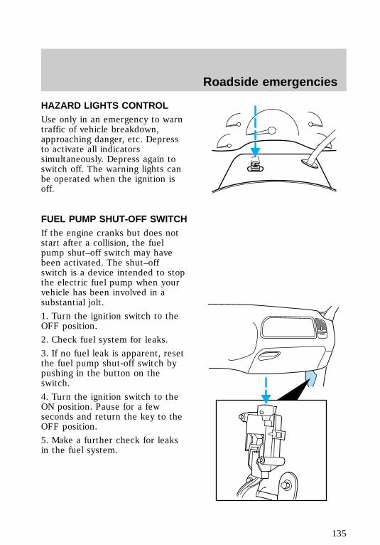
HAZARD LIGHTS CONTROLUse only in an emergency to warntraffic of vehicle breakdown,approaching danger, etc. Depressto activate all indicatorssimultaneously. Depress again toswitch off. The warning lights canbe operated when the ignition isoff.
FUEL PUMP SHUT-OFF SWITCHIf the engine cranks but does notstart after a collision, the fuelpump shut–off switch may havebeen activated. The shut–offswitch is a device intended to stopthe electric fuel pump when yourvehicle has been involved in asubstantial jolt.
1. Turn the ignition switch to theOFF position.
2. Check fuel system for leaks.
3. If no fuel leak is apparent, resetthe fuel pump shut-off switch bypushing in the button on theswitch.
4. Turn the ignition switch to theON position. Pause for a fewseconds and return the key to theOFF position.
5. Make a further check for leaksin the fuel system.
com_hazard_switch.01
com_fuel_shut-off.01
f12_fuses
Roadside emergencies
135
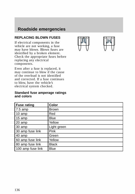
REPLACING BLOWN FUSESIf electrical components in thevehicle are not working, a fusemay have blown. Blown fuses areidentified by a broken element.Check the appropriate fuses beforereplacing any electricalcomponents.
Even after a fuse is replaced, itmay continue to blow if the causeof the overload is not identifiedand corrected. If a fuse continuesto blow, have the vehicle’selectrical system checked.
Standard fuse amperage ratingsand colors
Fuse rating Color7.5 amp Brown10 amp Red15 amp Blue20 amp Yellow30 amp Light green30 amp fuse link Pink40 amp Green60 amp fuse link Yellow80 amp fuse link Black100 amp fuse link Blue
Roadside emergencies
136
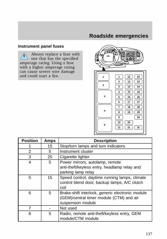
Instrument panel fuses
Always replace a fuse withone that has the specified
amperage rating. Using a fusewith a higher amperage ratingcan cause severe wire damageand could start a fire.
Position Amps Description1 15 Stop/turn lamps and turn indicators2 5 Instrument cluster3 25 Cigarette lighter4 5 Power mirrors, autolamp, remote
anti-theft/keyless entry, headlamp relay andparking lamp relay
5 15 Speed control, daytime running lamps, climatecontrol blend door, backup lamps, A/C clutchcoil
6 5 Brake-shift interlock, generic electronic module(GEM)/central timer module (CTM) and airsuspension module
7 - Not used8 5 Radio, remote anti-theft/keyless entry, GEM
module/CTM module
11
2
3
4
5
12 22
2 13 23
3 14 24
4
16
15 25
5 26
6 17 27
7 18 28
8 19 29
11 21 31
9 30
10 20
f12_pass_comp_fuses
Roadside emergencies
137
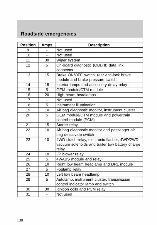
Position Amps Description9 - Not used10 - Not used11 30 Wiper system12 5 On-board diagnostic (OBD II) data link
connector13 15 Brake ON/OFF switch, rear anti-lock brake
module and brake pressure switch14 15 Interior lamps and accessory delay relay15 5 GEM module/CTM module16 20 High beam headlamps17 - Not used18 5 Instrument illumination19 10 Air bag diagnostic monitor, instrument cluster20 5 GEM module/CTM module and powertrain
control module (PCM)21 15 Starter relay22 10 Air bag diagnostic monitor and passenger air
bag deactivate switch23 10 4WD clutch relay, electronic flasher, 4WD/2WD
vacuum solenoids and trailer tow battery chargerelay
24 10 I/P blower relay25 5 4WABS module and relay26 10 Right low beam headlamp and DRL module27 5 Foglamp relay28 10 Left low beam headlamp29 5 Autolamp, instrument cluster, transmission
control indicator lamp and switch30 30 Ignition coils and PCM relay31 - Not used
Roadside emergencies
138
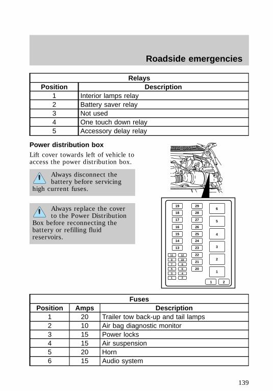
RelaysPosition Description
1 Interior lamps relay2 Battery saver relay3 Not used4 One touch down relay5 Accessory delay relay
Power distribution boxLift cover towards left of vehicle toaccess the power distribution box.
Always disconnect thebattery before servicing
high current fuses.
Always replace the coverto the Power Distribution
Box before reconnecting thebattery or refilling fluidreservoirs.
FusesPosition Amps Description
1 20 Trailer tow back-up and tail lamps2 10 Air bag diagnostic monitor3 15 Power locks4 15 Air suspension5 20 Horn6 15 Audio system
296
5
4
3
2
1
28
27
26
25
24
23
19
18
17
16
15
14
13
22
21
20
1 2
11
9
7
5
3
1
12
10
8
6
4
2
f12_eng_comp_fuses
Roadside emergencies
139
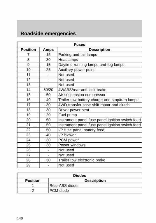
FusesPosition Amps Description
7 15 Parking and tail lamps8 30 Headlamps9 15 Daytime running lamps and fog lamps10 25 Auxiliary power point11 - Not used12 - Not used13 - Not used14 60/20 4WABS/rear anti-lock brake15 50 Air suspension compressor16 40 Trailer tow battery charge and stop/turn lamps17 30 4WD transfer case shift motor and clutch18 30 Driver power seat19 20 Fuel pump20 50 Instrument panel fuse panel ignition switch feed21 50 Instrument panel fuse panel ignition switch feed22 50 I/P fuse panel battery feed23 40 I/P blower24 30 PCM power25 30 Power windows26 - Not used27 - Not used28 30 Trailer tow electronic brake29 - Not used
DiodesPosition Description
1 Rear ABS diode2 PCM diode
Roadside emergencies
140
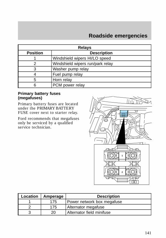
RelaysPosition Description
1 Windshield wipers HI/LO speed2 Windshield wipers run/park relay3 Washer pump relay4 Fuel pump relay5 Horn relay6 PCM power relay
Primary battery fuses(megafuses)Primary battery fuses are locatedunder the PRIMARY BATTERYFUSE cover next to starter relay.
Ford recommends that megafusesonly be serviced by a qualifiedservice technician.
Location Amperage Description1 175 Power network box megafuse2 175 Alternator megafuse3 20 Alternator field minifuse
1
2
3
f12_megafuse
Roadside emergencies
141
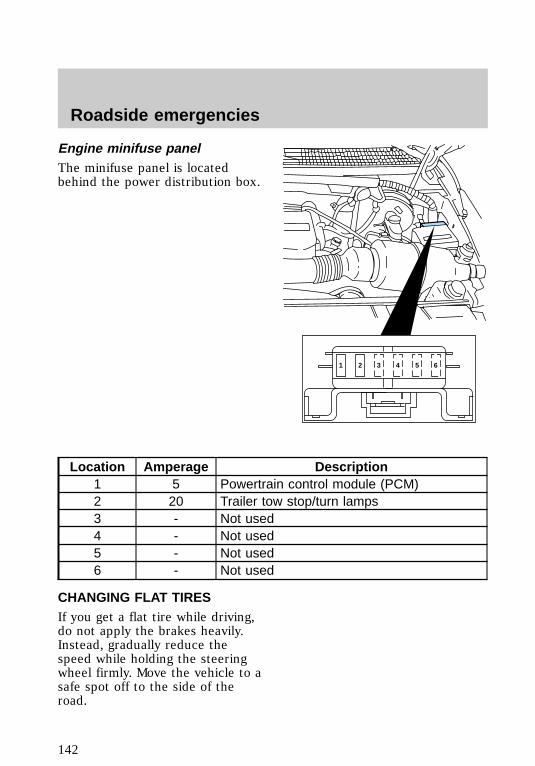
Engine minifuse panelThe minifuse panel is locatedbehind the power distribution box.
Location Amperage Description1 5 Powertrain control module (PCM)2 20 Trailer tow stop/turn lamps3 - Not used4 - Not used5 - Not used6 - Not used
CHANGING FLAT TIRESIf you get a flat tire while driving,do not apply the brakes heavily.Instead, gradually reduce thespeed while holding the steeringwheel firmly. Move the vehicle to asafe spot off to the side of theroad.
1 2 3 4 5 6
f12_minifuses
f12_flat_tires
f12_change_proc
Roadside emergencies
142
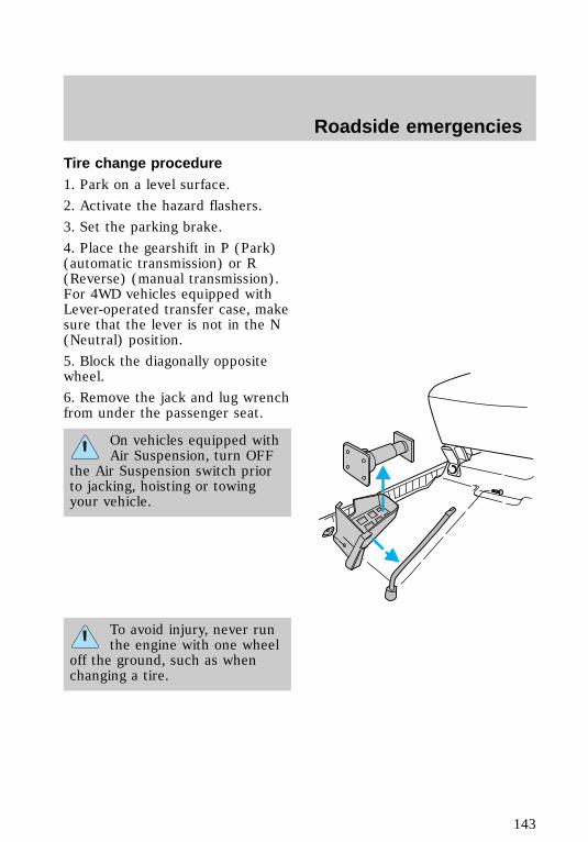
Tire change procedure1. Park on a level surface.
2. Activate the hazard flashers.
3. Set the parking brake.
4. Place the gearshift in P (Park)(automatic transmission) or R(Reverse) (manual transmission).For 4WD vehicles equipped withLever-operated transfer case, makesure that the lever is not in the N(Neutral) position.
5. Block the diagonally oppositewheel.
6. Remove the jack and lug wrenchfrom under the passenger seat.
On vehicles equipped withAir Suspension, turn OFF
the Air Suspension switch priorto jacking, hoisting or towingyour vehicle.
To avoid injury, never runthe engine with one wheel
off the ground, such as whenchanging a tire.
f12_removing_spare
Roadside emergencies
143
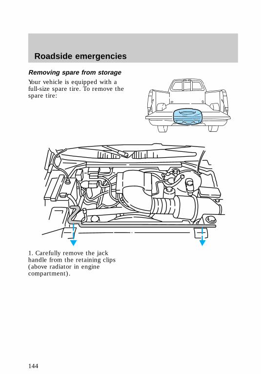
Removing spare from storageYour vehicle is equipped with afull-size spare tire. To remove thespare tire:
1. Carefully remove the jackhandle from the retaining clips(above radiator in enginecompartment).
Roadside emergencies
144

2. To lower the spare tire, insertthe jack handle into the rearbumper opening and turn itcounterclockwise.
Removing flat tire and installingspare1. Use the tip of the lug wrench toremove the wheel ornament. Insertthe lug wrench tip into the notchin the wheel ornament.
2. Loosen the wheel nuts with thelug wrench. Do not remove the lugnuts yet.
3. Position the jack as shown foryour specific vehicle (4WD or2WD). Use the thumbwheel toraise the jack to the desiredheight.
• Front (2WD)
f12_removing_flat
Roadside emergencies
145
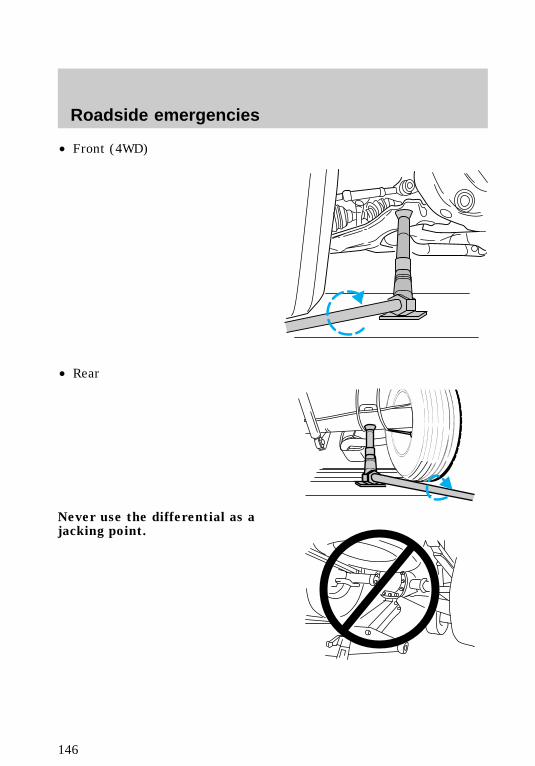
• Front (4WD)
• Rear
Never use the differential as ajacking point.
Roadside emergencies
146
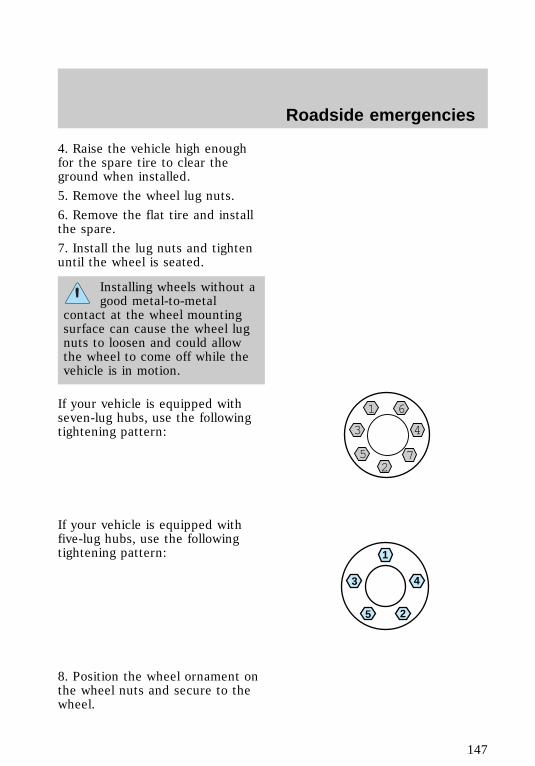
4. Raise the vehicle high enoughfor the spare tire to clear theground when installed.
5. Remove the wheel lug nuts.
6. Remove the flat tire and installthe spare.
7. Install the lug nuts and tightenuntil the wheel is seated.
Installing wheels without agood metal-to-metal
contact at the wheel mountingsurface can cause the wheel lugnuts to loosen and could allowthe wheel to come off while thevehicle is in motion.
If your vehicle is equipped withseven-lug hubs, use the followingtightening pattern:
If your vehicle is equipped withfive-lug hubs, use the followingtightening pattern:
8. Position the wheel ornament onthe wheel nuts and secure to thewheel.
1 6
3 4
752
1
4
25
3
Roadside emergencies
147
9. To stow the flat tire, lay the tireon the ground with the inboardside facing up. Install the retainerthrough the wheel center and slidethe wheel under the vehicle. Turnthe spare handle clockwise untilthe tire is raised to its originalposition underneath the vehicle.The spare handle ratchets whenthe tire is raised to the stowedposition. It will not allow you toovertighten.
10. Unblock the wheel.
11. Stow the jacking equipmentunder the passenger seat and stowthe jack handle in the enginecompartment.
12. As soon as possible, tighten thewheel nuts with a torque wrenchto 115–165 Nm (85–115 lb-ft).
JUMP STARTING YOURVEHICLE
The gases around thebattery can explode if
exposed to flames, sparks, or litcigarettes. An explosion couldresult in injury or vehicledamage.
Do not push-start yourvehicle. You could damage
the catalytic converter. Forfurther information, see JumperCables in the Index.
com_jump-starting.01
Roadside emergencies
148
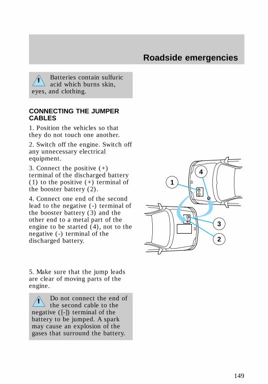
Batteries contain sulfuricacid which burns skin,
eyes, and clothing.
CONNECTING THE JUMPERCABLES1. Position the vehicles so thatthey do not touch one another.
2. Switch off the engine. Switch offany unnecessary electricalequipment.
3. Connect the positive (+)terminal of the discharged battery(1) to the positive (+) terminal ofthe booster battery (2).
4. Connect one end of the secondlead to the negative (-) terminal ofthe booster battery (3) and theother end to a metal part of theengine to be started (4), not to thenegative (-) terminal of thedischarged battery.
5. Make sure that the jump leadsare clear of moving parts of theengine.
Do not connect the end ofthe second cable to the
negative ([-]) terminal of thebattery to be jumped. A sparkmay cause an explosion of thegases that surround the battery.
+
–
+
–
3
2
1
4
com_connecting_cables.01
com_jump_starting.01
Roadside emergencies
149
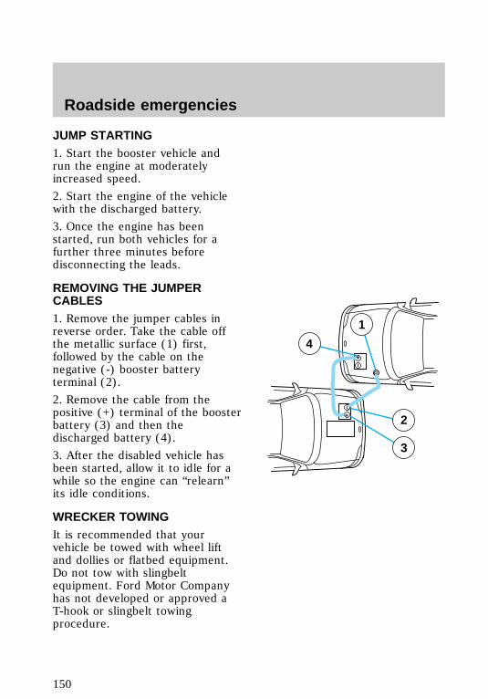
JUMP STARTING1. Start the booster vehicle andrun the engine at moderatelyincreased speed.
2. Start the engine of the vehiclewith the discharged battery.
3. Once the engine has beenstarted, run both vehicles for afurther three minutes beforedisconnecting the leads.
REMOVING THE JUMPERCABLES1. Remove the jumper cables inreverse order. Take the cable offthe metallic surface (1) first,followed by the cable on thenegative (-) booster batteryterminal (2).
2. Remove the cable from thepositive (+) terminal of the boosterbattery (3) and then thedischarged battery (4).
3. After the disabled vehicle hasbeen started, allow it to idle for awhile so the engine can “relearn”its idle conditions.
WRECKER TOWINGIt is recommended that yourvehicle be towed with wheel liftand dollies or flatbed equipment.Do not tow with slingbeltequipment. Ford Motor Companyhas not developed or approved aT-hook or slingbelt towingprocedure.
+
–
+
–
2
3
4
1
com_removing_cables.01
f12_wrecker
Roadside emergencies
150
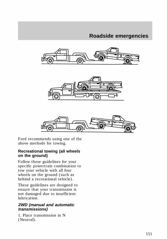
Ford recommends using one of theabove methods for towing.
Recreational towing (all wheelson the ground)Follow these guidelines for yourspecific powertrain combination totow your vehicle with all fourwheels on the ground (such asbehind a recreational vehicle).
These guidelines are designed toensure that your transmission isnot damaged due to insufficientlubrication.
2WD (manual and automatictransmissions)1. Place transmission in N(Neutral).
f12_recreational_towing
Roadside emergencies
151
2. Maximum speed is 56 km/h (35mph).
3. Maximum distance is 80 km (50miles).
If a distance of 80 km (50 miles)or a speed of 56 km/h (35 mph)must be exceeded, you mustdisconnect the rear driveshaft.With the rear driveshaftdisconnected, the maximum speedis 88 km/h (55 mph) and there areno mileage restrictions.
See your dealer for help withdisconnecting the driveshaft.
4WD – Lever operated transfercase (manual and automatictransmissions)1. Place transmission in P (Park).
2. Shift the transfer case to N(Neutral).
3. Lockout the center disconnectby capping off one of the frontaxle vacuum motor lines. See yourFord dealer for assistance.
4. Vehicle speed should not exceed88 km/h (55 mph) and there areno mileage restrictions.
4WD – Electronic shift transfercase1. Place transmission in N(Neutral).
2. Shift the transfer case to 2H(2WD high).
3. Lockout the center disconnectby capping off one of the frontaxle vacuum motor lines. See yourdealer for assistance.
Roadside emergencies
152
4. Maximum speed is 56 km/h (35mph).
5. Maximum distance is 80 km (50miles).
If a distance of 80 km (50 miles)or a speed of 56 km/h (35 mph)must be exceeded, you mustdisconnect the rear driveshaft.With the rear driveshaftdisconnected, the maximum speedis 88 km/h (55 mph) and there areno mileage restrictions.
See your dealer for help withdisconnecting the driveshaft.
Roadside emergencies
153
SERVICING YOUR VEHICLE
Service recommendationsTo help you service your vehicle:
• We highlight do-it-yourself itemsin the engine compartment foreasy location.
• As possible, we design parts thatcan be replaced without tools.
• We provide you with a “ServiceGuide” which makes trackingroutine service for your vehicleeasy.
If your vehicle requiresprofessional service, yourdealership can provide necessaryparts and service. Check your“Warranty Information Booklet” tofind out which parts and servicesare covered.
Use only recommended fuels,lubricants, fluids and service partsconforming to specifications.Motorcraft parts are designed andbuilt to provide the bestperformance in your vehicle.
Precautions when servicingyour vehicleBe especially careful wheninspecting or servicing yourvehicle. Here are some generalprecautions for your safety:
• Do not work on a hot engine.
• If you must work with theengine running, avoid wearingloose clothing or jewelry that
com_service_recommendations.01
com_precautions_servicing.02
Maintenance and care
154
could get caught in movingparts. Take precautions withlong hair.
• Do not work on a vehicle withthe engine running in anenclosed space, unless you aresure you have enoughventilation.
• Keep all lit cigarettes, openflames and other lit materialaway from the battery and allfuel related parts.
If you disconnect the battery, theengine must “relearn” its idleconditions before your vehicle willdrive properly, as explained inBattery in this chapter.
Working with the engine off• Automatic transmission
1. Set the parking brake fully andensure the gearshift is securelylatched in P (Park).
2. Turn off the engine and removethe key.
3. Block the wheels to prevent thevehicle from moving unexpectedly.
• Manual transmission
1. Set the parking brake, depressthe clutch and place the gearshiftin 1 (First).
2. Turn off the engine and removethe key.
3. Block the wheels to prevent thevehicle from moving unexpectedly.
Working with the engine on• Automatic transmission
com_working_off.02
com_working_on.02
Maintenance and care
155
1. Set the parking brake fully andensure the gearshift is securelylatched in P (Park).
2. Block the wheels to prevent thevehicle from moving unexpectedly.
Do not start your enginewith the air cleaner
removed and do not remove itwhile the engine is running.
• Manual transmission
1. Set the parking brake, depressthe clutch and place the gearshiftin 1 (First).
2. Block the wheels to prevent thevehicle from moving unexpectedly.
f12_opening_hood
Maintenance and care
156
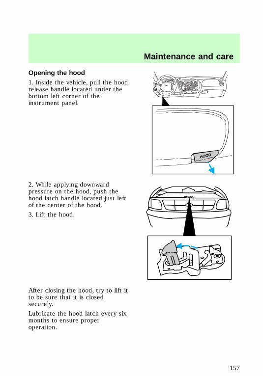
Opening the hood1. Inside the vehicle, pull the hoodrelease handle located under thebottom left corner of theinstrument panel.
2. While applying downwardpressure on the hood, push thehood latch handle located just leftof the center of the hood.
3. Lift the hood.
After closing the hood, try to lift itto be sure that it is closedsecurely.
Lubricate the hood latch every sixmonths to ensure properoperation.
HOOD
f12_4.2L_engine_components
Maintenance and care
157
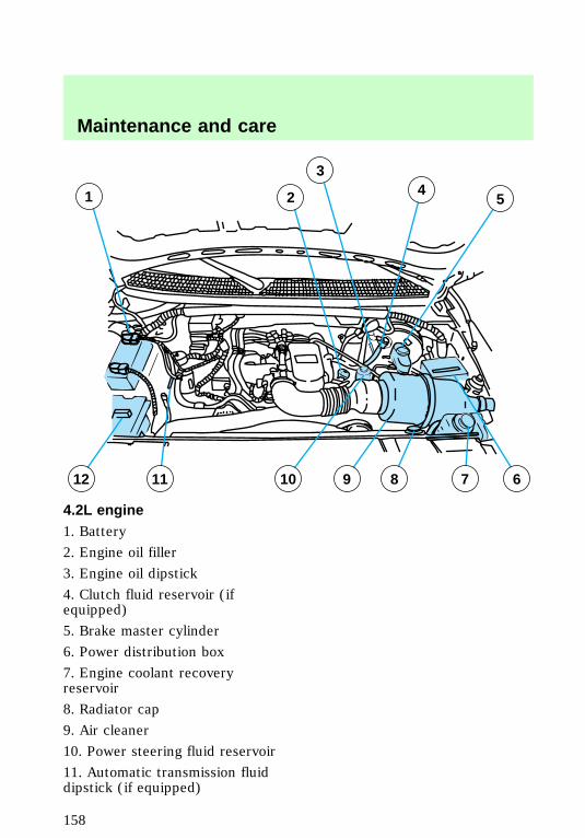
4.2L engine1. Battery
2. Engine oil filler
3. Engine oil dipstick
4. Clutch fluid reservoir (ifequipped)
5. Brake master cylinder
6. Power distribution box
7. Engine coolant recoveryreservoir
8. Radiator cap
9. Air cleaner
10. Power steering fluid reservoir
11. Automatic transmission fluiddipstick (if equipped)
1
12 89 7 611 10
2
34
5
Maintenance and care
158
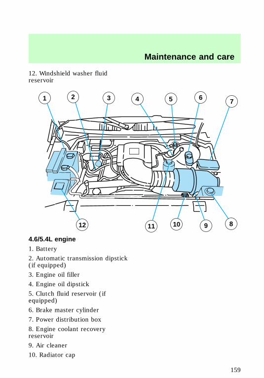
12. Windshield washer fluidreservoir
4.6/5.4L engine1. Battery
2. Automatic transmission dipstick(if equipped)
3. Engine oil filler
4. Engine oil dipstick
5. Clutch fluid reservoir (ifequipped)
6. Brake master cylinder
7. Power distribution box
8. Engine coolant recoveryreservoir
9. Air cleaner
10. Radiator cap
1011 812 9
1 2 4 5 673
f12_4.6L_5.4L_engine
Maintenance and care
159
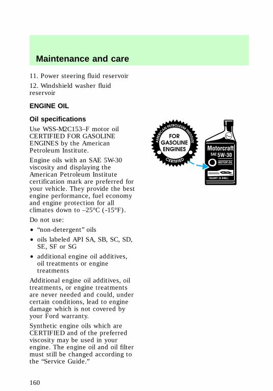
11. Power steering fluid reservoir
12. Windshield washer fluidreservoir
ENGINE OIL
Oil specificationsUse WSS-M2C153–F motor oilCERTIFIED FOR GASOLINEENGINES by the AmericanPetroleum Institute.
Engine oils with an SAE 5W-30viscosity and displaying theAmerican Petroleum Institutecertification mark are preferred foryour vehicle. They provide the bestengine performance, fuel economyand engine protection for allclimates down to –25°C (-15°F).
Do not use:
• “non-detergent” oils
• oils labeled API SA, SB, SC, SD,SE, SF or SG
• additional engine oil additives,oil treatments or enginetreatments
Additional engine oil additives, oiltreatments, or engine treatmentsare never needed and could, undercertain conditions, lead to enginedamage which is not covered byyour Ford warranty.
Synthetic engine oils which areCERTIFIED and of the preferredviscosity may be used in yourengine. The engine oil and oil filtermust still be changed according tothe “Service Guide.”
f12_engine_oil
f12_oil_specs
Maintenance and care
160
Oil filtersFord production and aftermarket(Motorcraft) oil filters are designedfor added engine protection andlong life. If a replacement oil filteris used that does not meet Fordmaterial and design specifications,startup engine noises or knockmay be experienced. It isrecommended that you use theappropriate Motorcraft oil filter (oranother brand meeting Fordspecifications) for your engineapplication.
Checking engine oilCheck the engine oil each time youfuel your vehicle.
Check the engine oil level morefrequently if the vehicle is carryinga heavy load, towing a trailer,idling for extended periods (likepolice, taxi or shuttle servicevehicles) or driven at high speedsfor extended periods of time.
To check the oil:
1. Make sure the vehicle is on levelground. If the engine is warm, turnthe engine off and wait a fewminutes for the oil to drain intothe oil pan.
2. Set the parking brake andensure the gearshift is latched in P(Park) (automatic transmission) or1 (First) (manual transmission).
3. Open the hood. Protect yourselffrom engine heat.
4. Locate and carefully remove the
f12_checking_oil
Maintenance and care
161
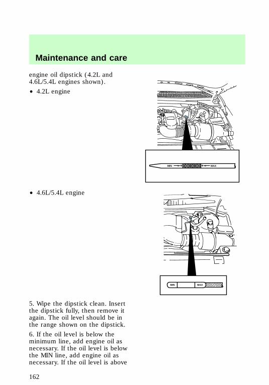
engine oil dipstick (4.2L and4.6L/5.4L engines shown).
• 4.2L engine
• 4.6L/5.4L engine
5. Wipe the dipstick clean. Insertthe dipstick fully, then remove itagain. The oil level should be inthe range shown on the dipstick.
6. If the oil level is below theminimum line, add engine oil asnecessary. If the oil level is belowthe MIN line, add engine oil asnecessary. If the oil level is above
MAXMIN
MAXMIN
Maintenance and care
162
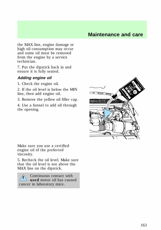
the MAX line, engine damage orhigh oil consumption may occurand some oil must be removedfrom the engine by a servicetechnician.
7. Put the dipstick back in andensure it is fully seated.
Adding engine oil1. Check the engine oil.
2. If the oil level is below the MINline, then add engine oil.
3. Remove the yellow oil filler cap.
4. Use a funnel to add oil throughthe opening.
Make sure you use a certifiedengine oil of the preferredviscosity.
5. Recheck the oil level. Make surethat the oil level is not above theMAX line on the dipstick.
Continuous contact withused motor oil has caused
cancer in laboratory mice.
f12_adding_oil
f12_brake_fluid
Maintenance and care
163
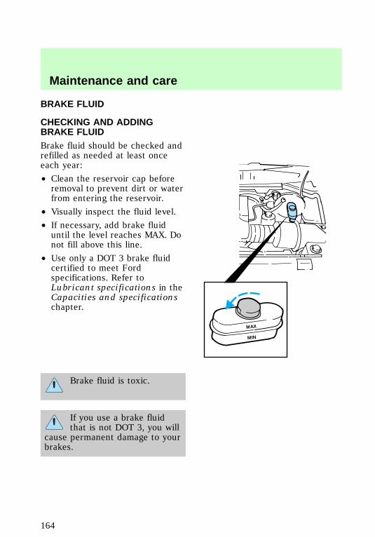
BRAKE FLUID
CHECKING AND ADDINGBRAKE FLUIDBrake fluid should be checked andrefilled as needed at least onceeach year:
• Clean the reservoir cap beforeremoval to prevent dirt or waterfrom entering the reservoir.
• Visually inspect the fluid level.
• If necessary, add brake fluiduntil the level reaches MAX. Donot fill above this line.
• Use only a DOT 3 brake fluidcertified to meet Fordspecifications. Refer toLubricant specifications in theCapacities and specificationschapter.
Brake fluid is toxic.
If you use a brake fluidthat is not DOT 3, you will
cause permanent damage to yourbrakes.
MAX
MIN
com_checking-adding_fluid.01
Maintenance and care
164
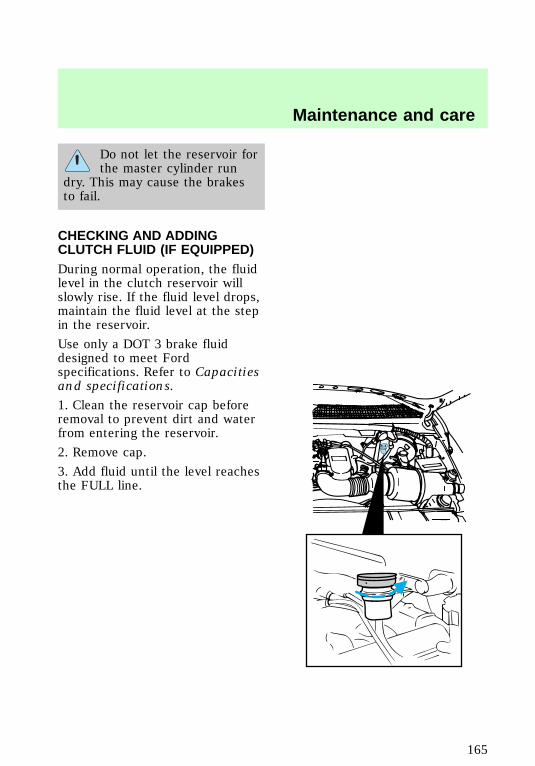
Do not let the reservoir forthe master cylinder run
dry. This may cause the brakesto fail.
CHECKING AND ADDINGCLUTCH FLUID (IF EQUIPPED)During normal operation, the fluidlevel in the clutch reservoir willslowly rise. If the fluid level drops,maintain the fluid level at the stepin the reservoir.
Use only a DOT 3 brake fluiddesigned to meet Fordspecifications. Refer to Capacitiesand specifications.
1. Clean the reservoir cap beforeremoval to prevent dirt and waterfrom entering the reservoir.
2. Remove cap.
3. Add fluid until the level reachesthe FULL line.
f12_clutch_fluid
f12_washer_fluid
Maintenance and care
165
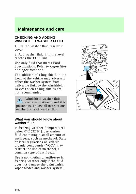
CHECKING AND ADDINGWINDSHIELD WASHER FLUID1. Lift the washer fluid reservoircover.
2. Add washer fluid intil the levelreaches the FULL line.
Use only fluid that meets FordSpecifications. Refer to Capacitiesand specifications.
The addition of a bug shield to thefront of the vehicle may adverselyaffect the washer system fromdelivering fluid to the windshield.Devices such as bug shields arenot recommended.
Windshield washer fluidcontains methanol and it is
poisonous. Follow all instructionson the bottle of washer fluid.
What you should know aboutwasher fluidIn freezing weather [temperaturesbelow 0°C (32°F)], use washerfluid containing a small amount ofantifreeze, such as methanol. Stateor local regulations on volatileorganic compounds (VOCs) mayrestrict the use of methanol, acommon type of antifreeze.
Use a non-methanol antifreeze infreezing weather only if the fluiddoes not damage the paint finish,wiper blades and washer system.
WASHER FLUID
ONLY
f12_wysk_washer_fluid
f12_coolant
Maintenance and care
166
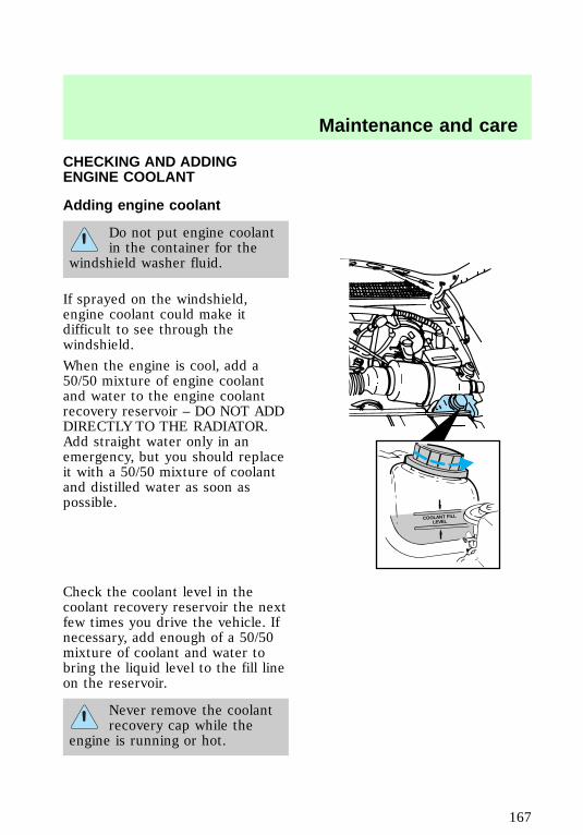
CHECKING AND ADDINGENGINE COOLANT
Adding engine coolant
Do not put engine coolantin the container for the
windshield washer fluid.
If sprayed on the windshield,engine coolant could make itdifficult to see through thewindshield.
When the engine is cool, add a50/50 mixture of engine coolantand water to the engine coolantrecovery reservoir – DO NOT ADDDIRECTLY TO THE RADIATOR.Add straight water only in anemergency, but you should replaceit with a 50/50 mixture of coolantand distilled water as soon aspossible.
Check the coolant level in thecoolant recovery reservoir the nextfew times you drive the vehicle. Ifnecessary, add enough of a 50/50mixture of coolant and water tobring the liquid level to the fill lineon the reservoir.
Never remove the coolantrecovery cap while the
engine is running or hot.
COOLANT FILLLEVEL
f12_adding_coolant
Maintenance and care
167
If you must remove the coolantrecovery cap, follow these steps toavoid personal injury:
1. Before you remove the cap, turnthe engine off and let it cool.
2. When the engine is cool, wrap athick cloth around the cap. Slowlyturn cap counterclockwise to thefirst stop.
3. Step back while the pressurereleases.
4. When you are sure that all thepressure has been released, usethe cloth to press the cap down,turn it counterclockwise andremove it.
Use Ford Premium Cooling SystemFluid E2FZ-19549–AA (in Canada,Motorcraft CXC-8–B) or anequivalent premium engine coolantthat meets Ford SpecificationESE-M97B44–A. Ford PremiumEngine Coolant is an optimizedformula that will protect all metalsand rubber elastomers used inFord cooling systems for 4 years or80,000 km (50,000 miles).
Do not use alcohol or methanolantifreeze or any engine coolantsmixed with alcohol or methanolantifreeze. Do not usesupplemental coolant additives inyour vehicle. These additives mayharm your engine cooling system.The use of an improper coolantmay void the warranty of yourvehicle’s engine cooling system.
f12_recycled_coolant
Maintenance and care
168
Recycled engine coolantFord Motor Company recommendsthat Ford and Lincoln-Mercurydealers use recycled enginecoolant produced byFord-approved processes. Not allcoolant recycling processesproduce coolant which meets Fordspecification ESE-M97B44–A, anduse of such coolant may harmengine and cooling systemcomponents.
Always dispose of usedautomotive fluids in a responsiblemanner. Follow your community’sregulations and standards forrecycling and disposing ofautomotive fluids.
Coolant refill capacityTo find out how much fluid yourvehicle’s cooling system can hold,refer to Refill capacities in theCapacities and specificationschapter.
Have your dealer check the enginecooling system for leaks if youhave to add more than a liter(quart) of engine coolant permonth.
Severe winter climateIf you drive in extremely coldclimates [less than 36°C (34°F)], itmay be necessary to increase thecoolant concentration above 50%.Refer to the chart on the coolantcontainer to ensure the coolantconcentration in your vehicle issuch that the coolant will not
f12_refill_capacity
f12_winter_climate
Maintenance and care
169
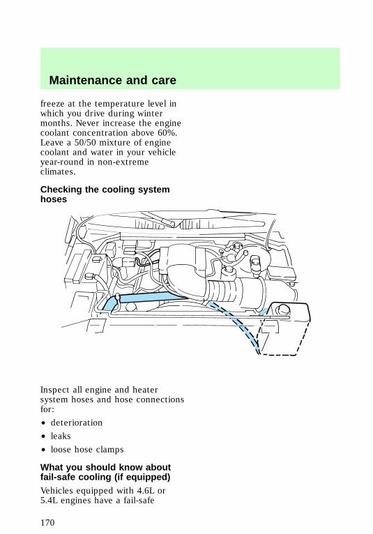
freeze at the temperature level inwhich you drive during wintermonths. Never increase the enginecoolant concentration above 60%.Leave a 50/50 mixture of enginecoolant and water in your vehicleyear-round in non-extremeclimates.
Checking the cooling systemhoses
Inspect all engine and heatersystem hoses and hose connectionsfor:
• deterioration
• leaks
• loose hose clamps
What you should know aboutfail-safe cooling (if equipped)Vehicles equipped with 4.6L or5.4L engines have a fail-safe
com_checking_hoses.01
f12_wysk_failsafe_cooling
Maintenance and care
170
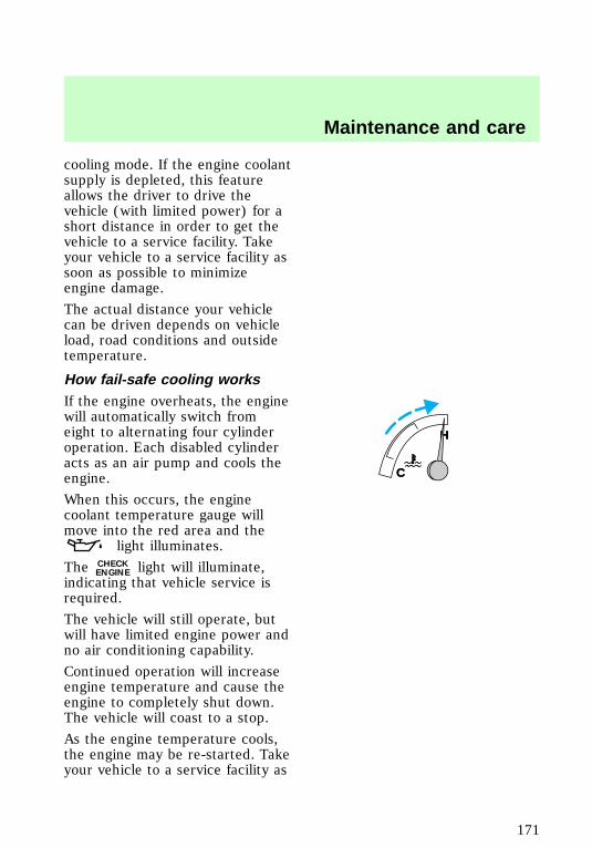
cooling mode. If the engine coolantsupply is depleted, this featureallows the driver to drive thevehicle (with limited power) for ashort distance in order to get thevehicle to a service facility. Takeyour vehicle to a service facility assoon as possible to minimizeengine damage.
The actual distance your vehiclecan be driven depends on vehicleload, road conditions and outsidetemperature.
How fail-safe cooling worksIf the engine overheats, the enginewill automatically switch fromeight to alternating four cylinderoperation. Each disabled cylinderacts as an air pump and cools theengine.
When this occurs, the enginecoolant temperature gauge willmove into the red area and the
light illuminates.
The CHECKENGINE light will illuminate,
indicating that vehicle service isrequired.
The vehicle will still operate, butwill have limited engine power andno air conditioning capability.
Continued operation will increaseengine temperature and cause theengine to completely shut down.The vehicle will coast to a stop.
As the engine temperature cools,the engine may be re-started. Takeyour vehicle to a service facility as
C
H
C
H
Maintenance and care
171
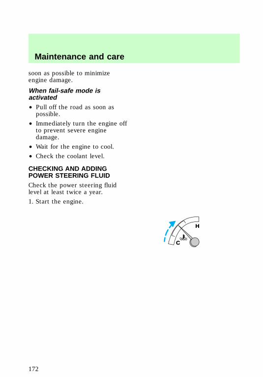
soon as possible to minimizeengine damage.
When fail-safe mode isactivated• Pull off the road as soon aspossible.
• Immediately turn the engine offto prevent severe enginedamage.
• Wait for the engine to cool.
• Check the coolant level.
CHECKING AND ADDINGPOWER STEERING FLUIDCheck the power steering fluidlevel at least twice a year.
1. Start the engine.
C
H
C
H
f12_power_steering
Maintenance and care
172
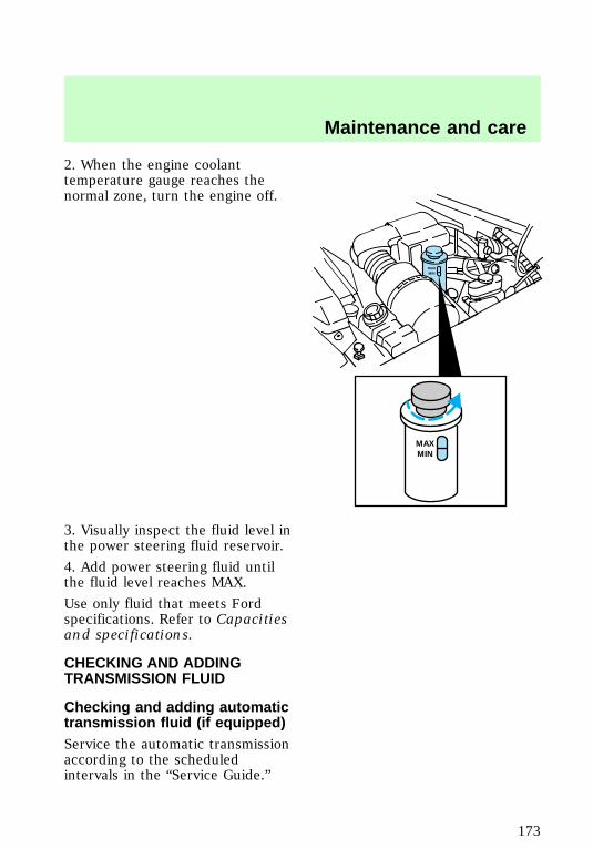
2. When the engine coolanttemperature gauge reaches thenormal zone, turn the engine off.
3. Visually inspect the fluid level inthe power steering fluid reservoir.
4. Add power steering fluid untilthe fluid level reaches MAX.
Use only fluid that meets Fordspecifications. Refer to Capacitiesand specifications.
CHECKING AND ADDINGTRANSMISSION FLUID
Checking and adding automatictransmission fluid (if equipped)Service the automatic transmissionaccording to the scheduledintervals in the “Service Guide.”
MAXMIN
MAXMIN
f12_trans_fluid
f12_checking_adding_autotrans
Maintenance and care
173
Before adding any fluid, make surethe correct type will be used. Thisinformation is indicated on thedipstick.
Do not drive the vehicle if the fluidlevel is below the bottom hole onthe blade type dipstick (4R70Wtransmission) or below the COLDarea on the bullet type dipstick(E4OD transmission) and outsidetemperatures are above 10°C(50°F).
Your vehicle does not use uptransmission fluid. However, it isrecommended that you check thetransmission fluid at least twice ayear. The fluid level should bechecked if the transmission is notworking properly, i.e., if thetransmission slips or shifts slowlyor if you notice some sign of fluidleakage.
It is preferable to check thetransmission fluid level at normaloperating temperature, afterapproximately 32 km (20 miles) ofdriving. However, you can checkthe fluid level without driving toobtain a normal operatingtemperature if the outsidetemperature is above 10°C (50°F).
If your vehicle has been operatedfor an extended period at highspeeds, in city traffic during hotweather or pulling a trailer, thevehicle should be turned off forabout 30 minutes to allow the fluidto cool before checking.
Maintenance and care
174
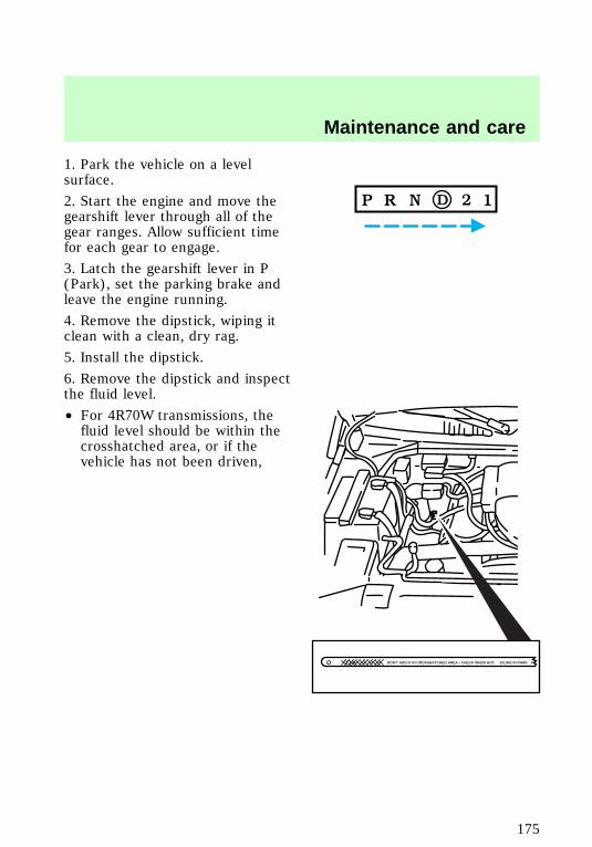
1. Park the vehicle on a levelsurface.
2. Start the engine and move thegearshift lever through all of thegear ranges. Allow sufficient timefor each gear to engage.
3. Latch the gearshift lever in P(Park), set the parking brake andleave the engine running.
4. Remove the dipstick, wiping itclean with a clean, dry rag.
5. Install the dipstick.
6. Remove the dipstick and inspectthe fluid level.
• For 4R70W transmissions, thefluid level should be within thecrosshatched area, or if thevehicle has not been driven,
DON'T ADD IF IN CROSSHATCHED AREA • CHECK WHEN HOT IDLING IN PARK
Maintenance and care
175
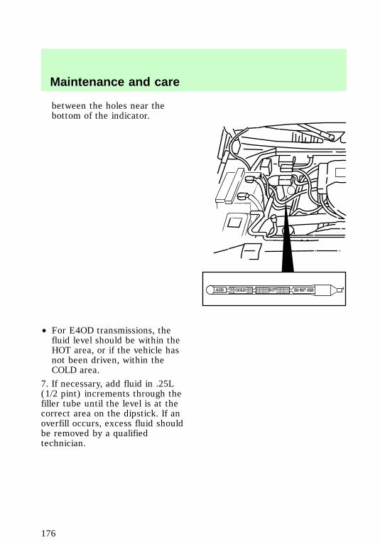
between the holes near thebottom of the indicator.
• For E4OD transmissions, thefluid level should be within theHOT area, or if the vehicle hasnot been driven, within theCOLD area.
7. If necessary, add fluid in .25L(1/2 pint) increments through thefiller tube until the level is at thecorrect area on the dipstick. If anoverfill occurs, excess fluid shouldbe removed by a qualifiedtechnician.
f12_check_add_man_trans_fluid
Maintenance and care
176

Checking and adding manualtransmission fluid (if equipped)1. Clean the filler plug.
2. Remove the filler plug andinspect the fluid level.
3. Fluid level should be at bottomof the opening.
4. Add only enough fluid throughthe filler opening so that the fluidlevel is 6 mm (3/8 in) from thebottom of the opening.
Use only fluid that meets Fordspecifications. Refer to theCapacities and specificationschapter.
f12_check_add_tcase_fluid
Maintenance and care
177
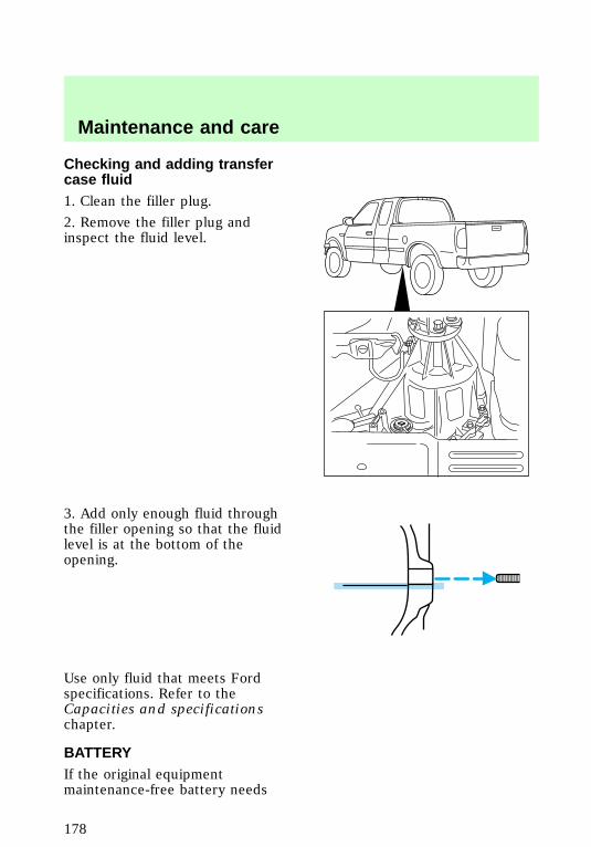
Checking and adding transfercase fluid1. Clean the filler plug.
2. Remove the filler plug andinspect the fluid level.
3. Add only enough fluid throughthe filler opening so that the fluidlevel is at the bottom of theopening.
Use only fluid that meets Fordspecifications. Refer to theCapacities and specificationschapter.
BATTERYIf the original equipmentmaintenance-free battery needs
f12_battery
Maintenance and care
178
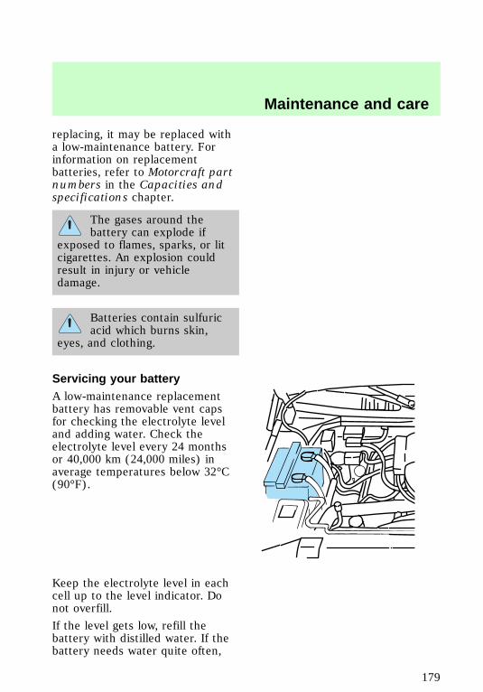
replacing, it may be replaced witha low-maintenance battery. Forinformation on replacementbatteries, refer to Motorcraft partnumbers in the Capacities andspecifications chapter.
The gases around thebattery can explode if
exposed to flames, sparks, or litcigarettes. An explosion couldresult in injury or vehicledamage.
Batteries contain sulfuricacid which burns skin,
eyes, and clothing.
Servicing your batteryA low-maintenance replacementbattery has removable vent capsfor checking the electrolyte leveland adding water. Check theelectrolyte level every 24 monthsor 40,000 km (24,000 miles) inaverage temperatures below 32°C(90°F).
Keep the electrolyte level in eachcell up to the level indicator. Donot overfill.
If the level gets low, refill thebattery with distilled water. If thebattery needs water quite often,
f12_servicing_battery
Maintenance and care
179
have the charging system checkedfor a possible malfunction.
Your vehicle is equipped with abattery saver feature designed toprevent your battery fromaccidental wear down due to doorsleft ajar. For information on thissystem, refer to the Controls andfeatures chapter.
Relearning idle conditionsBecause your vehicle’s engine iselectronically controlled by acomputer, some control conditionsare maintained by power from thebattery. When the battery isdisconnected or a new battery isinstalled, the computer must“relearn” its idle conditions beforeyour vehicle will drive properly. Tocomplete this process:
1. Put the gearshift in P(Park)(automatic transmission) orN (Neutral)(manual transmission).
2. Turn off all accessories, andstart the engine.
3. Let the engine idle for at leastone minute.
4. The relearning process willautomatically complete as youdrive the vehicle.
• If you do not allow the engine torelearn its idle, the idle qualityof your vehicle may be adverselyaffected until the idle iseventually relearned.
• If the battery has beendisconnected or a new batteryhas been installed, the clock and
Maintenance and care
180

preset radio stations must bereset once the battery isreconnected.
• Always dispose of usedautomotive batteries in aresponsible manner. Follow yourcommunity’s standards fordisposal. Call your localrecycling center to find outmore about recycling automotivebatteries.
CHANGING THE AIR FILTER1. Loosen the clamp that securesthe air cleaner in place.
2. Separate the two halves of theair cleaner.
3. Remove the air filter elementfrom the open end of the engineair cleaner and replace it with anew element. Be careful not tocrimp the filter edges betweenhalves. This could cause filterdamage if not properly seated.
4. Replace the two halves of theair cleaner and secure the clamp.
For information on replacement airfilter elements, refer to theCapacities and specificationschapter.
REPLACING THE WIPERBLADESIf the windshield wiper blades donot work properly after cleaning,replacement of the blade elementmay be necessary.
To replace the windshield wiperblades:
f12_changing_air_filter
f12_changing_wiper_blades
Maintenance and care
181
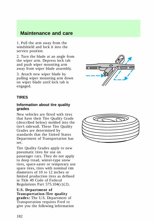
1. Pull the arm away from thewindshield and lock it into theservice position.
2. Turn the blade at an angle fromthe wiper arm. Depress lock taband push wiper mounting armaway from wiper blade assembly.
3. Attach new wiper blade bypulling wiper mounting arm downon wiper blade until lock tab isengaged.
TIRES
Information about tire qualitygradesNew vehicles are fitted with tiresthat have their Tire Quality Grade(described below) molded into thetire’s sidewall. These Tire QualityGrades are determined bystandards that the United StatesDepartment of Transportation hasset.
Tire Quality Grades apply to newpneumatic tires for use onpassenger cars. They do not applyto deep tread, winter-type snowtires, space-saver or temporary usespare tires, tires with nominal rimdiameters of 10 to 12 inches orlimited production tires as definedin Title 49 Code of FederalRegulations Part 575.104(c)(2).
U.S. Department ofTransportation-Tire qualitygrades: The U.S. Department ofTransportation requires Ford togive you the following information
f12_maint_tires
com_about_tire_grades.01
Maintenance and care
182
about tire grades exactly as thegovernment has written it.
TreadwearThe treadwear grade is acomparative rating based on thewear rate of the tire when testedunder controlled conditions on aspecified government test course.For example, a tire grade 150would wear one and one-half (11/2) times as well on thegovernment course as a tire grade100. The relative performance oftires depends upon the actualconditions of their use, however,and may depart significantly fromthe norm due to variations indriving habits, service practices,and differences in roadcharacteristics and climate.
Traction A B CThe traction grades, from highestto lowest are A, B, and C, and theyrepresent the tire’s ability to stopon wet pavement as measuredunder test surfaces of asphalt andconcrete. A tire marked C mayhave poor traction performance.Warning: The traction gradeassigned to this tire is based onbraking (straightahead) tractiontests and does not includecornering (turning) traction.
Temperature A B CThe temperature grades are A (thehighest), B, and C, representingthe tire’s resistance to thegeneration of heat and its ability todissipate heat when tested under
com_treadwear.01
com_traction_abc.01
com_temperature_abc.01
Maintenance and care
183
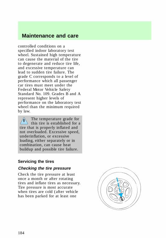
controlled conditions on aspecified indoor laboratory testwheel. Sustained high temperaturecan cause the material of the tireto degenerate and reduce tire life,and excessive temperature canlead to sudden tire failure. Thegrade C corresponds to a level ofperformance which all passengercar tires must meet under theFederal Motor Vehicle SafetyStandard No. 109. Grades B and Arepresent higher levels ofperformance on the laboratory testwheel than the minimum requiredby law.
The temperature grade forthis tire is established for a
tire that is properly inflated andnot overloaded. Excessive speed,underinflation, or excessiveloading, either separately or incombination, can cause heatbuildup and possible tire failure.
Servicing the tires
Checking the tire pressureCheck the tire pressure at leastonce a month or after rotatingtires and inflate tires as necessary.Tire pressure is most accuratewhen tires are cold (after vehiclehas been parked for at least one
f12_servicing_tires
Maintenance and care
184
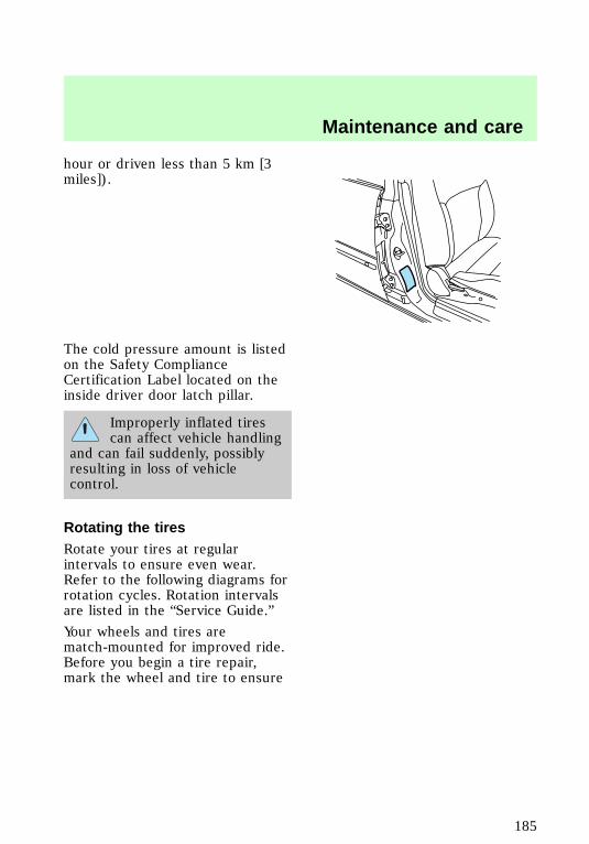
hour or driven less than 5 km [3miles]).
The cold pressure amount is listedon the Safety ComplianceCertification Label located on theinside driver door latch pillar.
Improperly inflated tirescan affect vehicle handling
and can fail suddenly, possiblyresulting in loss of vehiclecontrol.
Rotating the tiresRotate your tires at regularintervals to ensure even wear.Refer to the following diagrams forrotation cycles. Rotation intervalsare listed in the “Service Guide.”
Your wheels and tires arematch-mounted for improved ride.Before you begin a tire repair,mark the wheel and tire to ensure
f12_rotating_tires
Maintenance and care
185
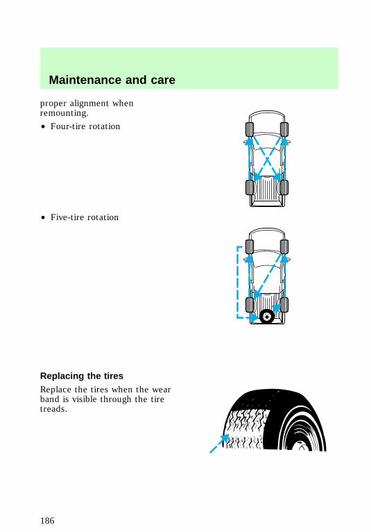
proper alignment whenremounting.
• Four-tire rotation
• Five-tire rotation
Replacing the tiresReplace the tires when the wearband is visible through the tiretreads.
f12_replacing_tires
Maintenance and care
186
When replacing full sizetires, never mix radial,
bias-belted, or bias-type tires.Use only the tire sizes that arelisted on the tire pressure decal.Make sure that all tires are thesame size, speed rating, andload-carrying capacity. Use onlythe tire combinationsrecommended on the decal. Ifyou do not follow theseprecautions, your vehicle maynot drive properly and safely.
Make sure that allreplacement tires are of
the same size, type, load-carryingcapacity and tread design (e.g.,“All Terrain”, etc.), as originallyoffered by Ford.
Do not replace your tireswith “high performance“
tires or larger size tires.
Failure to follow theseprecautions may adversely
affect the handling of the vehicleand make it easier to lose controland roll over.
Identifying tire typesRefer to the Safety ComplianceCertification Label to determinethe specific size tire and wheelFord Motor Company recommendsfor use on this vehicle.
f12_iden_tire_types
f12_snow_tires
Maintenance and care
187
Snow tires and chains
Snow tires must be thesame size and grade as the
tires you currently have on yourvehicle.
The tires on your vehicle have allweather treads to provide tractionin rain and snow.
However, in some climates, youmay need to use snow tires andchains.
Follow these guidelines when usingsnow tires and chains.
• Use only SAE Class “S” chains.
• Install chains securely, verifyingthat the chains do not touch anywiring, brake lines or fuel lines.
• 4x2: Install tire chains on reartires (of all sizes) only.
• 4x4: Install tire chains on reartires (of all sizes), and on fronttires of size P235/70R16 only.
• Drive cautiously. If you hear thechains rub or bang against yourvehicle, stop and retighten thechains. If this does not work,remove the chains to preventdamage to your vehicle.
• If possible, avoid fully loadingyour vehicle.
• Remove the tire chains whenthey are no longer needed. Donot use tire chains on dry roads.
• The suspension insulation andbumpers will help preventvehicle damage. Do not remove
Maintenance and care
188
these components from yourvehicle when using snow tiresand chains.
FUEL
Important safety precautions
Do not overfill the fueltank. The pressure in an
overfilled tank may causeleakage and lead to fuel sprayand fire.
If you do not use theproper fuel cap, the
pressure in the fuel tank candamage the fuel system or causeit to work improperly in acollision.
The fuel system may beunder pressure. If the fuel
cap is venting vapor or if youhear a hissing sound, wait until itstops before completelyremoving the cap.
Automotive fuels cancause serious injury or
death if misused or mishandled.
f12_fuel_info
com_important_precautions.06
Maintenance and care
189
Observe the following guidelineswhen handling automotive fuel:
• Extinguish all smoking materialsand any open flames beforefueling your vehicle.
• Always turn off the vehiclebefore fueling.
• Automotive fuels can be harmfulor fatal if swallowed. If fuel isswallowed, call a physicianimmediately, even if nosymptoms are immediatelyapparent. The toxic affects offuel may not be visible forhours.
• Fuels can also be harmful ifabsorbed through the skin. Iffuel is splashed on the skin,promptly remove contaminatedclothing and wash skinthoroughly with soap and water.
• If fuel is splashed in the eyes,remove contact lenses, flushwith water for 15 minutes andseek medical attention.
• Be particularly careful if you aretaking “Antabuse” or otherforms of disulfiram for thetreatment of alcoholism.Breathing gasoline vapors orskin contact could cause anadverse reaction. Consult aphysician immediately.
Choosing the right fuelUse only UNLEADED FUEL. Theuse of leaded fuel is prohibited bylaw and could damage your
com_choosing_fuel.01
Maintenance and care
190
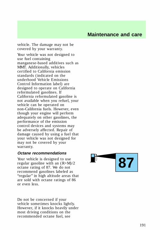
vehicle. The damage may not becovered by your warranty.
Your vehicle was not designed touse fuel containingmanganese-based additives such asMMT. Additionally, vehiclescertified to California emissionstandards (indicated on theunderhood Vehicle EmissionsControl Information label) aredesigned to operate on Californiareformulated gasolines. IfCalifornia reformulated gasoline isnot available when you refuel, yourvehicle can be operated onnon-California fuels. However, eventhough your engine will performadequately on other gasolines, theperformance of the emissioncontrol devices and systems maybe adversely affected. Repair ofdamage caused by using a fuel thatyour vehicle was not designed formay not be covered by yourwarranty.
Octane recommendationsYour vehicle is designed to useregular gasoline with an (R+M)/2octane rating of 87. We do notrecommend gasolines labeled as“regular” in high altitude areas thatare sold with octane ratings of 86or even less.
Do not be concerned if yourvehicle sometimes knocks lightly.However, if it knocks heavily undermost driving conditions on therecommended octane fuel, see
87
com_octane_recommendations.01
Maintenance and care
191
your dealer or a qualified servicetechnician to prevent any enginedamage.
Fuel qualityIf you are experiencing starting,rough idle or hesitation problemstry a different brand of fuel. If thecondition persists, see your dealeror a qualified service technician.
The American AutomobileManufacturers Association (AAMA)issued a gasoline specification toprovide information on high qualityfuels that optimize theperformance of your vehicle. Werecommend the use of gasolinesthat meet the AAMA specificationif they are available.
It should not be necessary to addany aftermarket products to yourfuel tank if you continue to use ahigh-quality fuel.
Cleaner airFord approves the use of gasolinesto improve air quality, includingreformulated gasolines, thatcontain oxygenates such as amaximum of 10% ethanol or 15%MTBE. There should be no morethan 5% methanol with cosolventsand additives to protect the fuelsystem.
Calculating fuel economyTo accurately calculate yourvehicle’s fuel economy:
1. Fill the tank completely andrecord the initial odometerreading.
com_fuel_quality.01
f12_cleaner_air
f12_calculating_economy
Maintenance and care
192

2. Each time you fill the tank,record the amount of fuel added(in liters or gallons).
3. After at least three to five fueltank fill-ups, fill the fuel tank andrecord the current mileagereading.
4. Use one of the followingequations to calculate fueleconomy.
Liters used x 100 4 Totalkilometers traveled = km/liter.
Total miles traveled 4 Totalgallons used = mpg.
5. Keep a record for at least onemonth. This will provide anaccurate estimate of the vehicle’sfuel economy.
f12_wysk_emission_control
Maintenance and care
193
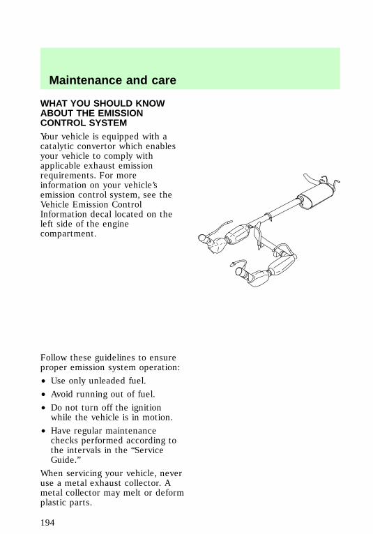
WHAT YOU SHOULD KNOWABOUT THE EMISSIONCONTROL SYSTEMYour vehicle is equipped with acatalytic convertor which enablesyour vehicle to comply withapplicable exhaust emissionrequirements. For moreinformation on your vehicle’semission control system, see theVehicle Emission ControlInformation decal located on theleft side of the enginecompartment.
Follow these guidelines to ensureproper emission system operation:
• Use only unleaded fuel.
• Avoid running out of fuel.
• Do not turn off the ignitionwhile the vehicle is in motion.
• Have regular maintenancechecks performed according tothe intervals in the “ServiceGuide.”
When servicing your vehicle, neveruse a metal exhaust collector. Ametal collector may melt or deformplastic parts.
Maintenance and care
194
Do not park, idle, or driveyour vehicle in dry grass
or other dry ground cover. Theemission system heats up theengine compartment and exhaustsystem, which can start a fire.
If you smell exhaust fumesinside your vehicle, have
your dealer inspect your vehicleimmediately. Do not drive if yousmell exhaust fumes.
On vehicles withoutoriginal equipment floor
covering or insulation, do not letpassengers ride in your truck ina manner that allows contactbetween skin and the metal floor.
If you notice one or more of thefollowing, the emissions systemmay not be working properly. Haveyour vehicle serviced as soon aspossible.
• Fluid leaks
• The or CHECKENGINE lights
illuminate in the instrumentcluster and remain lit
• Strange odors
• Engine runs more than fiveseconds after shut-off or enginemisfires, surges, stalls orbackfires
• Loss of oil pressure.f12_important_emissions_info
Maintenance and care
195
Important emission controlinformationBy law, anyone who manufacturers,repairs, services, sells, leases,trades vehicles or supervises afleet of vehicles is not permitted tointentionally remove an emissioncontrol device or prevent it fromworking.
Do not make any unauthorizedchanges to the vehicle or engine.
Changes that cause moreunburned fuel to reach the exhaustsystem can increase thetemperature of the engine orexhaust system.
Preparing your vehicle forinspection/maintenance testingIn some localities it may become alegal requirement to pass anInspection/Maintenance test of theon-board diagnostic (OBDII)system. If the vehicle’s powertrainsystem or battery has just beenserviced, the OBD II system isreset to a “not ready for I/Mtesting condition.” To ready theOBD II system for I/M testing, thelaw specifies that additional mixedcity and highway driving isnecessary to complete the check ofthe OBD II system.
The driving modes required toreach the ready condition consistof a minimum of 30 minutes of cityand highway driving as describedbelow:
f12_readiness_im_testing
Maintenance and care
196
• 20 minutes of driving in stopand go city-type traffic with atleast four idle periods.
• 10 minutes of driving on anexpressway or highway.
Before completing the abovedriving modes, the engine must bewarmed up and at operatingtemperature. Once started, thevehicle must not be turned offduring the above driving modes.
Maintenance and care
197
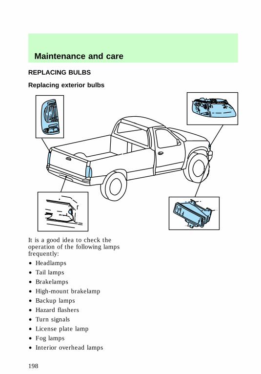
REPLACING BULBS
Replacing exterior bulbs
It is a good idea to check theoperation of the following lampsfrequently:
• Headlamps
• Tail lamps
• Brakelamps
• High-mount brakelamp
• Backup lamps
• Hazard flashers
• Turn signals
• License plate lamp
• Fog lamps
• Interior overhead lamps
f12_replacing_bulbs
Maintenance and care
198

Do not remove lamp bulbs unlessthey will be replaced immediately.If a bulb is removed for anextended period of time,contaminants may enter the lampand affect performance.
Replacing headlamp bulbs
Handle a halogenheadlamp bulb carefully
and keep out of children’s reach.Grasp the bulb only by its plasticbase and do not touch the glass.The oil from your hand couldcause the bulb to break the nexttime the headlamps areoperated.
1. Make sure that the headlampcontrol is in the position.
2. Open the hood.
3. At the back of the headlamp,pull clips rearward and up 19 mm(about 3/4 in.) to release theheadlamp assembly.
f12_headlamps_turnsignals
Maintenance and care
199
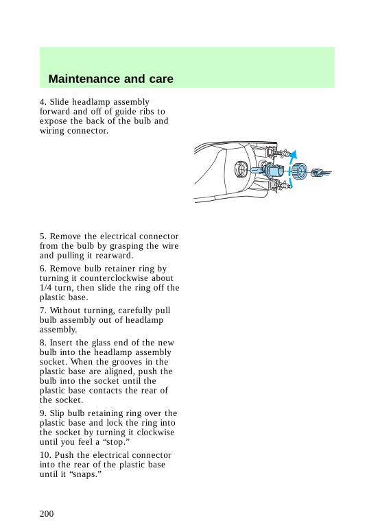
4. Slide headlamp assemblyforward and off of guide ribs toexpose the back of the bulb andwiring connector.
5. Remove the electrical connectorfrom the bulb by grasping the wireand pulling it rearward.
6. Remove bulb retainer ring byturning it counterclockwise about1/4 turn, then slide the ring off theplastic base.
7. Without turning, carefully pullbulb assembly out of headlampassembly.
8. Insert the glass end of the newbulb into the headlamp assemblysocket. When the grooves in theplastic base are aligned, push thebulb into the socket until theplastic base contacts the rear ofthe socket.
9. Slip bulb retaining ring over theplastic base and lock the ring intothe socket by turning it clockwiseuntil you feel a “stop.”
10. Push the electrical connectorinto the rear of the plastic baseuntil it “snaps.”
Maintenance and care
200
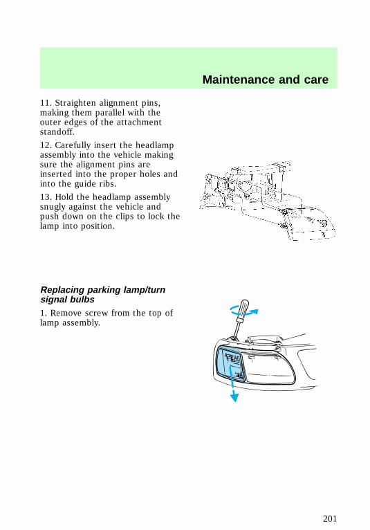
11. Straighten alignment pins,making them parallel with theouter edges of the attachmentstandoff.
12. Carefully insert the headlampassembly into the vehicle makingsure the alignment pins areinserted into the proper holes andinto the guide ribs.
13. Hold the headlamp assemblysnugly against the vehicle andpush down on the clips to lock thelamp into position.
Replacing parking lamp/turnsignal bulbs1. Remove screw from the top oflamp assembly.
Maintenance and care
201
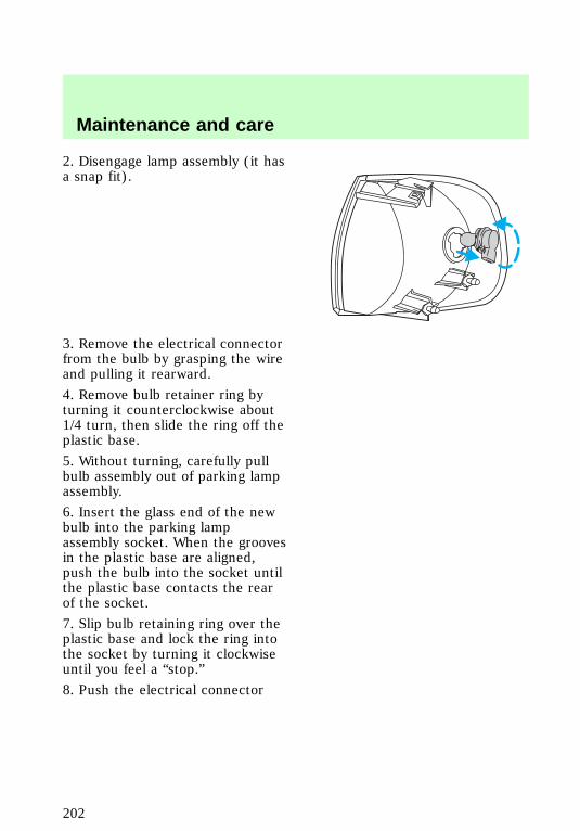
2. Disengage lamp assembly (it hasa snap fit).
3. Remove the electrical connectorfrom the bulb by grasping the wireand pulling it rearward.
4. Remove bulb retainer ring byturning it counterclockwise about1/4 turn, then slide the ring off theplastic base.
5. Without turning, carefully pullbulb assembly out of parking lampassembly.
6. Insert the glass end of the newbulb into the parking lampassembly socket. When the groovesin the plastic base are aligned,push the bulb into the socket untilthe plastic base contacts the rearof the socket.
7. Slip bulb retaining ring over theplastic base and lock the ring intothe socket by turning it clockwiseuntil you feel a “stop.”
8. Push the electrical connector
Maintenance and care
202
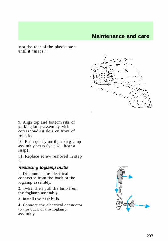
into the rear of the plastic baseuntil it “snaps.”
9. Align top and bottom ribs ofparking lamp assembly withcorresponding slots on front ofvehicle.
10. Push gently until parking lampassembly seats (you will hear asnap).
11. Replace screw removed in step1.
Replacing foglamp bulbs1. Disconnect the electricalconnector from the back of thefoglamp assembly.
2. Twist, then pull the bulb fromthe foglamp assembly.
3. Install the new bulb.
4. Connect the electrical connectorto the back of the foglampassembly.
f12_foglamps
f12_tail_lamps
Maintenance and care
203
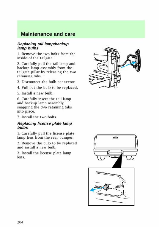
Replacing tail lamp/backuplamp bulbs1. Remove the two bolts from theinside of the tailgate.
2. Carefully pull the tail lamp andbackup lamp assembly from thetailgate pillar by releasing the tworetaining tabs.
3. Disconnect the bulb connector.
4. Pull out the bulb to be replaced.
5. Install a new bulb.
6. Carefully insert the tail lampand backup lamp assembly,snapping the two retaining tabsinto place.
7. Install the two bolts.
Replacing license plate lampbulbs1. Carefully pull the license platelamp lens from the rear bumper.
2. Remove the bulb to be replacedand install a new bulb.
3. Install the license plate lamplens.
f12_license_plate_lamps
f12_dome_lamp
Maintenance and care
204
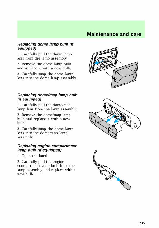
Replacing dome lamp bulb (ifequipped)1. Carefully pull the dome lamplens from the lamp assembly.
2. Remove the dome lamp bulband replace it with a new bulb.
3. Carefully snap the dome lamplens into the dome lamp assembly.
Replacing dome/map lamp bulb(if equipped)1. Carefully pull the dome/maplamp lens from the lamp assembly.
2. Remove the dome/map lampbulb and replace it with a newbulb.
3. Carefully snap the dome lamplens into the dome/map lampassembly.
Replacing engine compartmentlamp bulb (if equipped)1. Open the hood.
2. Carefully pull the enginecompartment lamp bulb from thelamp assembly and replace with anew bulb.
f12_dome_map_lamp
f12_engine_compart
f12_exterior_bulb_specs
Maintenance and care
205
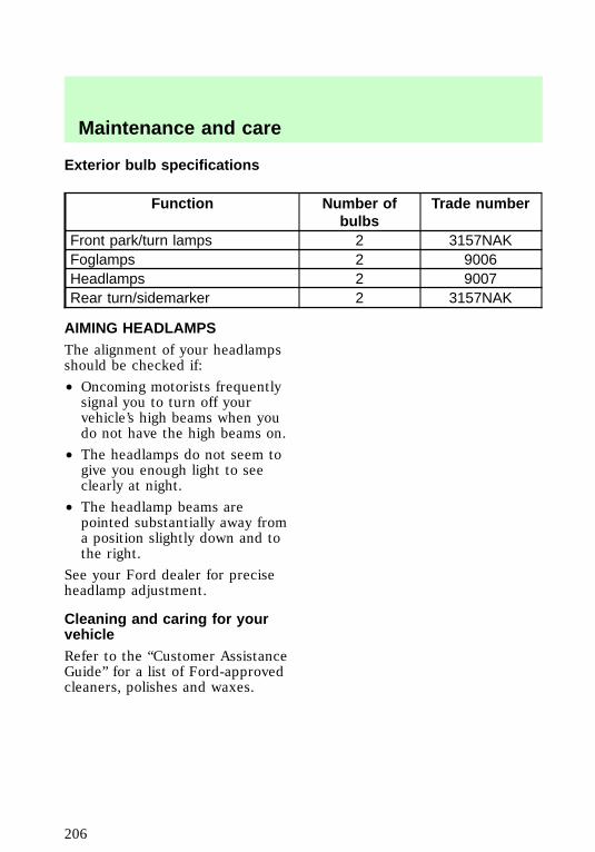
Exterior bulb specifications
Function Number ofbulbs
Trade number
Front park/turn lamps 2 3157NAKFoglamps 2 9006Headlamps 2 9007Rear turn/sidemarker 2 3157NAK
AIMING HEADLAMPSThe alignment of your headlampsshould be checked if:
• Oncoming motorists frequentlysignal you to turn off yourvehicle’s high beams when youdo not have the high beams on.
• The headlamps do not seem togive you enough light to seeclearly at night.
• The headlamp beams arepointed substantially away froma position slightly down and tothe right.
See your Ford dealer for preciseheadlamp adjustment.
Cleaning and caring for yourvehicleRefer to the “Customer AssistanceGuide” for a list of Ford-approvedcleaners, polishes and waxes.
f12_aiming_hlamps
f12_cleaning_your_vehicle
com_cleaning_caring.01
com_washing_vehicle.01
Maintenance and care
206
Washing your vehicleWash your vehicle regularly withcold or lukewarm water. Never usestrong detergents or soap. If yourvehicle is particularly dirty, use aquality car wash detergent. Alwaysuse a clean sponge, washing gloveor similar device and plenty ofwater for best results. To avoidspots, avoid washing when thehood is still warm, immediatelyafter or during exposure to strongsunlight.
During winter months, it isespecially important to wash thevehicle on a regular basis. Largequantities of dirt and road salt aredifficult to remove, and they alsocause damage to the vehicle.Remove any exterior accessories,such as antennas, before enteringa car wash.
• After washing, apply the brakesseveral times to dry them.
Waxing your vehicleThe best way to determine whenthe paintwork needs waxing is bynoting when water stops beadingon the surface. This could be everythree or four months, dependingon operating conditions.
Use only carnauba orsynthetic-based waxes. Removeany bugs and tar before waxingvehicle. Use cleaning fluid oralcohol with a clean cloth toremove. Use tar remover toremove any tar spots.
com_waxing_vehicle.01
com_repairing_chips
Maintenance and care
207
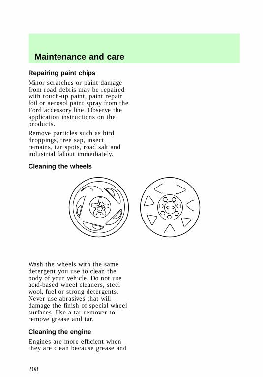
Repairing paint chipsMinor scratches or paint damagefrom road debris may be repairedwith touch-up paint, paint repairfoil or aerosol paint spray from theFord accessory line. Observe theapplication instructions on theproducts.
Remove particles such as birddroppings, tree sap, insectremains, tar spots, road salt andindustrial fallout immediately.
Cleaning the wheels
Wash the wheels with the samedetergent you use to clean thebody of your vehicle. Do not useacid-based wheel cleaners, steelwool, fuel or strong detergents.Never use abrasives that willdamage the finish of special wheelsurfaces. Use a tar remover toremove grease and tar.
Cleaning the engineEngines are more efficient whenthey are clean because grease and
f12_cleaning_wheels
com_engine_cleaning.01
Maintenance and care
208
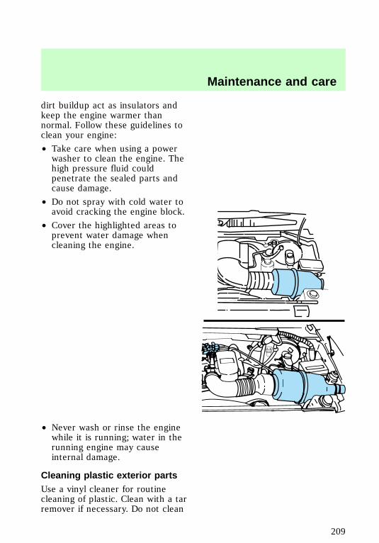
dirt buildup act as insulators andkeep the engine warmer thannormal. Follow these guidelines toclean your engine:
• Take care when using a powerwasher to clean the engine. Thehigh pressure fluid couldpenetrate the sealed parts andcause damage.
• Do not spray with cold water toavoid cracking the engine block.
• Cover the highlighted areas toprevent water damage whencleaning the engine.
• Never wash or rinse the enginewhile it is running; water in therunning engine may causeinternal damage.
Cleaning plastic exterior partsUse a vinyl cleaner for routinecleaning of plastic. Clean with a tarremover if necessary. Do not clean
com_plastic_exterior.01
Maintenance and care
209
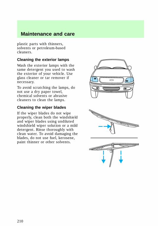
plastic parts with thinners,solvents or petroleum-basedcleaners.
Cleaning the exterior lampsWash the exterior lamps with thesame detergent you used to washthe exterior of your vehicle. Useglass cleaner or tar remover ifnecessary.
To avoid scratching the lamps, donot use a dry paper towel,chemical solvents or abrasivecleaners to clean the lamps.
Cleaning the wiper bladesIf the wiper blades do not wipeproperly, clean both the windshieldand wiper blades using undilutedwindshield wiper solution or a milddetergent. Rinse thoroughly withclean water. To avoid damaging theblades, do not use fuel, kerosene,paint thinner or other solvents.
com_exterior_lamps.01
com_wiper_cleaning.01
com_instru-panel_cleaning.01
Maintenance and care
210
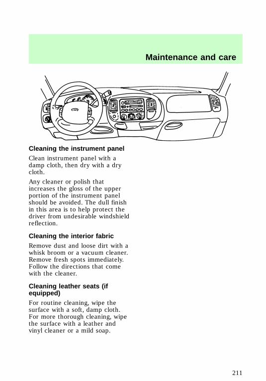
Cleaning the instrument panelClean instrument panel with adamp cloth, then dry with a drycloth.
Any cleaner or polish thatincreases the gloss of the upperportion of the instrument panelshould be avoided. The dull finishin this area is to help protect thedriver from undesirable windshieldreflection.
Cleaning the interior fabricRemove dust and loose dirt with awhisk broom or a vacuum cleaner.Remove fresh spots immediately.Follow the directions that comewith the cleaner.
Cleaning leather seats (ifequipped)For routine cleaning, wipe thesurface with a soft, damp cloth.For more thorough cleaning, wipethe surface with a leather andvinyl cleaner or a mild soap.
com_int_fabric_cleaning.01
com_leather_seats_cleaning.01
f12_cleaning_safety_belts
Maintenance and care
211
Cleaning and maintaining thesafety beltsClean the safety belts with a mildsoap solution recommended forcleaning upholstery or carpets. Donot bleach or dye the belts,because these actions may weakenthe belt webbing.
Check your safety belt systemperiodically to make sure that itworks properly and is notdamaged. If the webbing showsany wear, nicks or cuts, have itexamined by a qualified technicianto determine if replacement isnecessary. Always have your safetybelt system checked after acollision by a qualified technician.Refer to Safety belt maintenancein the Seating and safetyrestraints chapter for moreinformation.
Maintenance and care
212

MOTORCRAFT PART NUMBERS
ComponentEngine
4.2L 4.6L 5.4LSparkplug-platinum1
AWSF-42EE AWSF-32PP AWSF-22F
Air filter FA-1632 FA-1632 FA-1632Fuel filter FG-872 FG-872 FG-872Oil filter FL-400-S FL-820-S FL-820-SPCV valve EV-152 EV-98 EV-233
Battery
BXT-59(manual)
BXT-65-750(automatic)
BXT-59(manual)
BXT-65-750(automatic)
BXT-59(manual)
BXT-65-750(automatic)
1Replacement double platinum spark plug 9EE9 will replace 9E9 and9EG9 and 9P9 will replace 9P9 and 9PG9 suffixed plugs. Refer to theEngine data chart for spark plug gap specifications.
REFILL CAPACITIES
FluidFord partname
Vehicle type Capacity
Axle; frontFord 22.35cm (8.8 in)Ring Gear
4WD 1.65L (3.5 pts.)
Axle; rear
Ford 22.35cm (8.8 in)and 24.76 cm(9.75 in) RingGearConventionaland Traction-Lok(1)
F-150 2.6L (5.5 pts.)
f12_motorcraft_part
f12_refill
Capacities and specifications
213
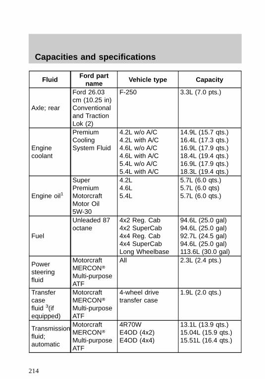
FluidFord partname
Vehicle type Capacity
Axle; rear
Ford 26.03cm (10.25 in)Conventionaland TractionLok (2)
F-250 3.3L (7.0 pts.)
Enginecoolant
PremiumCoolingSystem Fluid
4.2L w/o A/C4.2L with A/C4.6L w/o A/C4.6L with A/C5.4L w/o A/C5.4L with A/C
14.9L (15.7 qts.)16.4L (17.3 qts.)16.9L (17.9 qts.)18.4L (19.4 qts.)16.9L (17.9 qts.)18.3L (19.4 qts.)
Engine oil1
SuperPremiumMotorcraftMotor Oil5W-30
4.2L4.6L5.4L
5.7L (6.0 qts.)5.7L (6.0 qts)5.7L (6.0 qts.)
Fuel
Unleaded 87octane
4x2 Reg. Cab4x2 SuperCab4x4 Reg. Cab4x4 SuperCabLong Wheelbase
94.6L (25.0 gal)94.6L (25.0 gal)92.7L (24.5 gal)94.6L (25.0 gal)113.6L (30.0 gal)
Powersteeringfluid
MotorcraftMERCONTMulti-purposeATF
All 2.3L (2.4 pts.)
Transfercasefluid 3(ifequipped)
MotorcraftMERCONTMulti-purposeATF
4-wheel drivetransfer case
1.9L (2.0 qts.)
Transmissionfluid;automatic
MotorcraftMERCONTMulti-purposeATF
4R70WE4OD (4x2)E4OD (4x4)
13.1L (13.9 qts.)15.04L (15.9 qts.)15.51L (16.4 qts.)
Capacities and specifications
214
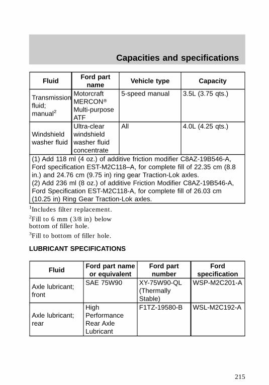
FluidFord partname
Vehicle type Capacity
Transmissionfluid;manual2
MotorcraftMERCONTMulti-purposeATF
5-speed manual 3.5L (3.75 qts.)
Windshieldwasher fluid
Ultra-clearwindshieldwasher fluidconcentrate
All 4.0L (4.25 qts.)
(1) Add 118 ml (4 oz.) of additive friction modifier C8AZ-19B546-A,Ford specification EST-M2C118–A, for complete fill of 22.35 cm (8.8in.) and 24.76 cm (9.75 in) ring gear Traction-Lok axles.(2) Add 236 ml (8 oz.) of additive Friction Modifier C8AZ-19B546-A,Ford Specification EST-M2C118-A, for complete fill of 26.03 cm(10.25 in) Ring Gear Traction-Lok axles.1Includes filter replacement.2Fill to 6 mm (3/8 in) belowbottom of filler hole.3Fill to bottom of filler hole.
LUBRICANT SPECIFICATIONS
FluidFord part nameor equivalent
Ford partnumber
Fordspecification
Axle lubricant;front
SAE 75W90 XY-75W90-QL(ThermallyStable)
WSP-M2C201-A
Axle lubricant;rear
HighPerformanceRear AxleLubricant
F1TZ-19580-B WSL-M2C192-A
f12_lube
Capacities and specifications
215
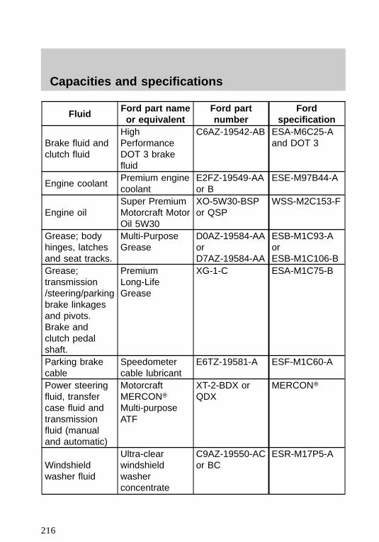
FluidFord part nameor equivalent
Ford partnumber
Fordspecification
Brake fluid andclutch fluid
HighPerformanceDOT 3 brakefluid
C6AZ-19542-AB ESA-M6C25-Aand DOT 3
Engine coolantPremium enginecoolant
E2FZ-19549-AAor B
ESE-M97B44-A
Engine oilSuper PremiumMotorcraft MotorOil 5W30
XO-5W30-BSPor QSP
WSS-M2C153-F
Grease; bodyhinges, latchesand seat tracks.
Multi-PurposeGrease
D0AZ-19584-AAorD7AZ-19584-AA
ESB-M1C93-AorESB-M1C106-B
Grease;transmission/steering/parkingbrake linkagesand pivots.Brake andclutch pedalshaft.
PremiumLong-LifeGrease
XG-1-C ESA-M1C75-B
Parking brakecable
Speedometercable lubricant
E6TZ-19581-A ESF-M1C60-A
Power steeringfluid, transfercase fluid andtransmissionfluid (manualand automatic)
MotorcraftMERCONTMulti-purposeATF
XT-2-BDX orQDX
MERCONT
Windshieldwasher fluid
Ultra-clearwindshieldwasherconcentrate
C9AZ-19550-ACor BC
ESR-M17P5-A
Capacities and specifications
216
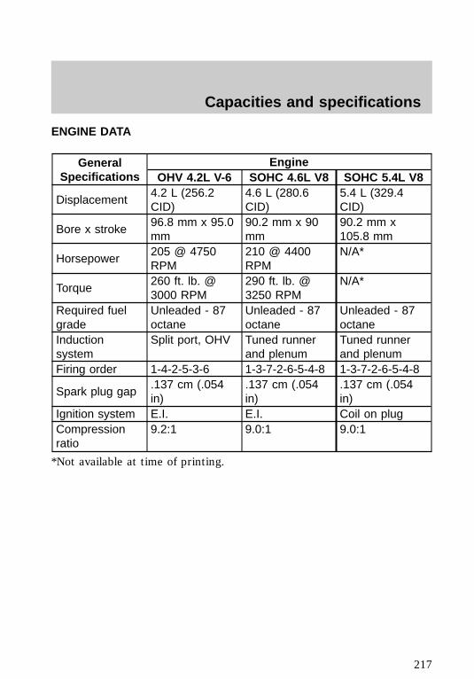
ENGINE DATA
GeneralSpecifications
EngineOHV 4.2L V-6 SOHC 4.6L V8 SOHC 5.4L V8
Displacement4.2 L (256.2CID)
4.6 L (280.6CID)
5.4 L (329.4CID)
Bore x stroke96.8 mm x 95.0mm
90.2 mm x 90mm
90.2 mm x105.8 mm
Horsepower205 @ 4750RPM
210 @ 4400RPM
N/A*
Torque260 ft. lb. @3000 RPM
290 ft. lb. @3250 RPM
N/A*
Required fuelgrade
Unleaded - 87octane
Unleaded - 87octane
Unleaded - 87octane
Inductionsystem
Split port, OHV Tuned runnerand plenum
Tuned runnerand plenum
Firing order 1-4-2-5-3-6 1-3-7-2-6-5-4-8 1-3-7-2-6-5-4-8
Spark plug gap.137 cm (.054in)
.137 cm (.054in)
.137 cm (.054in)
Ignition system E.I. E.I. Coil on plugCompressionratio
9.2:1 9.0:1 9.0:1
*Not available at time of printing.
f12_engine_data
f12_vehicle_dimensions
Capacities and specifications
217
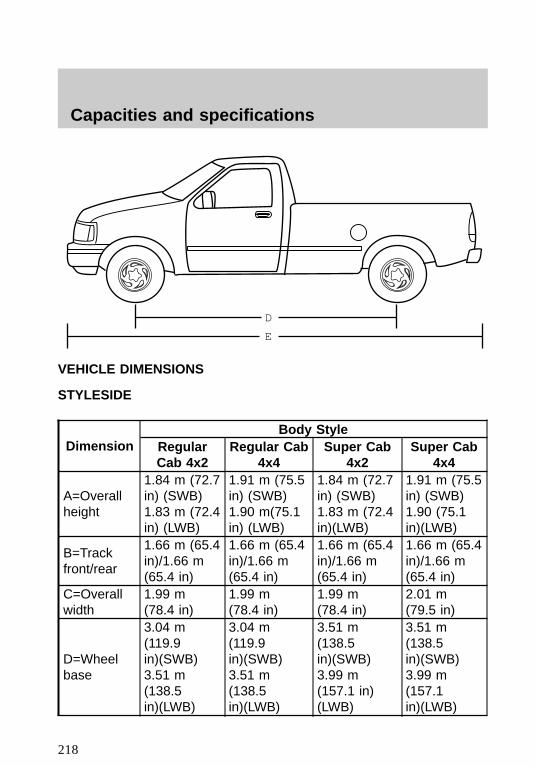
VEHICLE DIMENSIONS
STYLESIDE
DimensionBody Style
RegularCab 4x2
Regular Cab4x4
Super Cab4x2
Super Cab4x4
A=Overallheight
1.84 m (72.7in) (SWB)1.83 m (72.4in) (LWB)
1.91 m (75.5in) (SWB)1.90 m(75.1in) (LWB)
1.84 m (72.7in) (SWB)1.83 m (72.4in)(LWB)
1.91 m (75.5in) (SWB)1.90 (75.1in)(LWB)
B=Trackfront/rear
1.66 m (65.4in)/1.66 m(65.4 in)
1.66 m (65.4in)/1.66 m(65.4 in)
1.66 m (65.4in)/1.66 m(65.4 in)
1.66 m (65.4in)/1.66 m(65.4 in)
C=Overallwidth
1.99 m(78.4 in)
1.99 m(78.4 in)
1.99 m(78.4 in)
2.01 m(79.5 in)
D=Wheelbase
3.04 m(119.9in)(SWB)3.51 m(138.5in)(LWB)
3.04 m(119.9in)(SWB)3.51 m(138.5in)(LWB)
3.51 m(138.5in)(SWB)3.99 m(157.1 in)(LWB)
3.51 m(138.5in)(SWB)3.99 m(157.1in)(LWB)
D
E
f12_styleside
Capacities and specifications
218
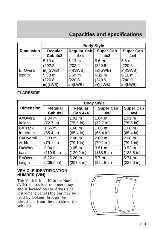
DimensionBody Style
RegularCab 4x2
Regular Cab4x4
Super Cab4x2
Super Cab4x4
E=Overalllength
5.13 m(202.2in)(SWB)5.60 m(220.8in)(LWB)
5.13 m(202.2in)(SWB)5.60 m(220.8in)(LWB)
5.6 m(220.8in)(SWB)6.11 m(240.9in)(LWB)
5.6 m(220.8in)(SWB)6.11 m(240.9in)(LWB)
FLARESIDE
DimensionBody Style
RegularCab 4x2
RegularCab 4x4
Super Cab4x2
Super Cab4x4
A=Overallheight
1.84 m(72.7 in)
1.91 m(75.5 in)
1.84 m(72.7 in)
1.91 m(75.5 in)
B=Trackfront/rear
1.66 m(65.4 in)
1.66 m(65.4 in)
1.66 m(65.4 in)
1.66 m(65.4 in)
C=Overallwidth
2.00 m(79.1 in)
2.00 m(79.1 in)
2.00 m(79.1 in)
2.00 m(79.1 in)
D=Wheelbase
3.04 m(119.9 in)
3.05 m(120.2 in)
3.51 m(138.5 in)
3.52 m(138.8 in)
E=Overalllength
5.22 m(205.9 in)
5.26 m(207.4 in)
5.7 m(224.5 in)
5.74 m(226.0 in)
VEHICLE IDENTIFICATIONNUMBER (VIN)The Vehicle Identification Number(VIN) is attached to a metal tagand is located on the driver sideinstrument panel (the tag may beread by looking through thewindshield from the outside of thevehicle).
f12_flareside
f12_vin
Capacities and specifications
219
REPORTING SAFETY DEFECTSIf you believe that your vehicle hasa defect that could cause a crash,or could cause injury or death, youshould immediately inform theNational Highway Traffic SafetyAdministration (NHTSA) inaddition to Ford Motor Company.
If NHTSA receives similarcomplaints, it may open aninvestigation, and if it finds that asafety defect exists in a group ofvehicles, it may order a recall andremedy campaign. However,NHTSA cannot become involved inindividual problems between you,your dealer or Ford MotorCompany.
To contact NHTSA, you may eithercall the Auto Safety Hotlinetoll-free at 1–800–424–9393(202–366–0123 in the WashingtonD.C. area) or write to:
NHTSA
U.S. Department of Transportation
400 Seventh Street
Washington D.C. 20590
You can also obtain otherinformation about motor vehiclesafety from the Hotline.
f12_reporting
Reporting safety defects
220


![Floor Strippers - Home | RJ Schinner Floor... · [Floor Care] 22 [Floor Care] 23 Floor Finishes & Sealers KEY CHARACTERISTICS BEST FOR PRODUCT CODE % OFF-THE-MOP MAINTENANCE SEMI-PERMANENT](https://img.pdfslide.us/doc/110x75/5b846d957f8b9a784a8c4361/floor-strippers-home-rj-schinner-floor-floor-care-22-floor-care-23.jpg)