Embed Size (px)
Citation preview

MAINTENANCE MANUAL
FAX: 816-472-1999 PHONE: 816-472-8999
TOLL FREE : 1-800-235-2829 E-MAIL: [email protected]

Machine Specificationsfor
Caribbean Broilers, LtdSRS No.: RS42011591300Web: 420Index: 240Loading: 650Discharge: 750Voltage: 220V 3ph/60 HzProduct Descriptions:
1. 2:1 Configuration 2:12. 2:2 Configuration 2:23. 3:2 Configuration 3:24. 3:1 Configuration 3:1
Die Configurations:420/240(2:1) (2:2) (3:2) (3:1)
RS Flexible Material Specifications:Form Web: 423 +/- 1mmNon-Form Web 406 +/- 1mm
Machine ComponentsHeater RodsELR R60104 form Bent Heater Rods 3ELR R60104 seal Bent Heater Rods 2 3
BladdersPRS 455492 Bladders 2Bladders 2 0Bladders 3 0
Seal GasketsPLA 155101 (2:1 Configuration) 1PLA 155104 (2:2 Configuration) 1PLA 155106 (3:2 Configuration) 1PLA 245126 (3:1 Configuration) 1
Infeed StationFUG464396 Assm, Film Unwind (Upper Unwind)F 420 1ARS451796 Toolbox RS Series 1
Forming StationSTL463735 Assm, Forming Station 1PRS457282 Assm, pneumatic panel 1PRS458690 Assm, form heat valve 1VAR461669 Assm, F vac vlv C version 1
Loading StationSTL463262 Assm, Knee Free 420/650 1FTR462244 K Chain 15.96FTR462413 K Chain Master Link 2STL460984 Assm, Short Mach. Kit 1
Sealing StationSTL463005 Assm, Seal Station 420 1ELR463834 Assm, Electrical Panel 1FUG464206 Assm, NF unwind 420 1PRS456273 Assm, pneu sl st 1VAR458343 Assm, vc vlv mnST 1 1
Discharge StationSTL463388 Assm, disc 420/750 1TRM460216 Assm, trim revlv trim removal 1ARS466208 Assm, Water Cooler Proficool (VC Kansas City) 1SGS462292 Assm, disc Safety Fingers 1
Cutting StationLTC451961 Assm, Rotary knife quick release shft 420 2LTC452487 Assm, Rotary knife assembly 1LTCR60148 Assm, Rotary knife hub assembly 7CCT457863 Assm, cross cut knife 420 1
Vacuum SystemsVAR462535 Assm, Busch RA-100 (VC Kansas City) 1(Sealing)
Printers/LabelersPLC454895 Assm, cd statnry 420 1PLC464526 Coder, 2inch CCI 3PLC452092 3/16 alphanumeric font set 6
Language StickersARS452484 English Stickers 1

Caribbean Broilers RS42011591300 CCA751458 220v/60HzDie Components
Dept Part # Description Qty Material P/N DATE/RACK
DFT 245010 form die top 420/240 1 458125
DHP 245020 heater plate 420/240 (REV.2) 2 458132
DHP 245020_1 htr back plate 420/240 2 BS
DHP 245024 form heat plate 420/240 (pyramid) 1 458132
DFB 245031 form die bottom 420/240-135 1 459313
DFD 245230 div.set 420/240 2:1 1 458129
DFD 155043 div.set 420/240 2:2 1 458129
DFD 245221 div.set 420/240 3:1 1 458129
DFD 245642 div.set 420/240 3:2 1 458129
DFD 245902 d.wall md 420/240/19.05 6 BS
DFD 155046 d wall 420/2ac/19.05 2 BS
DFD 245643 d wall 420/3ac/19.05 3 BS
DFP 245703 fill plates 420/240 1 BS
DFR 155051 radius plate 420/240 2:1 2 BS
DFR 155054 radius plate 420/240 2:2 4 BS
DFR 245223 radius plate 420/240 3:1 3 BS
DFR 245650 radius plate 420/240 3:2 6 BS
DST 245061 bladder seal die top 420/240 1 458326
DPP 245070 bladder pusher plate 420/240 (REV.1) 1 458131
DSP 245071 total seal 420/240 (REV.2) 1 458132
DSB 245081 seal die bottom 420/240 (REV.1) 1 459106
DSS 245234 seal frame 420/240 2:1 gskt155101 1 458134
DSS 155094 seal frame 420/240 2:2 gskt155104 1 458134
DSS 245226 seal frame 420/240 3:1 gskt245126 1 458134
DSS 245690 seal frame 420/240 3:2 gskt155106 1 458134
PSP 245342 240/1680 loadsuprail SS 2 BS
PSP 245353 240/450 dis rail p1 2 BS
PSP 245337 420/240/750 platform 1 BS
DCA 245506 infeed die spacer 240/1680 2 BS
DCA 245507 exit die spacer 240/1680 2 BS
SGS 460510 assm, F grd 420/240/1680 R (R64112) rev;1 1 EXISTING 1"x336x658
SGS 461335 assm, F grd 420/240/1680 L (R64702) rev;1 1 EXISTING 1"x450x658
SGS 461271 assm, S grd 420/240/1680 R (R64653) rev;1 1 EXISTING 1"x450x658
SGS 460250 assm, S grd 420/240/1680 L R63904) rev;1 1 EXISTING 1"x367x658
SGS 466393 assm, C grd 420x450-100R (R67318) 1 EXISTING

TABLE OF CONTENTS
SECTION 1 – SAFETY SECTION 2 – TRANSPORTATION SECTION 3 – INSTALLATION SECTION 4 – INTERFACE / TOUCH SCREEN SECTION 5 – MAINTENANCE & INSPECTION SCHEDULE SECTION 6 – TROUBLESHOOTING GUIDE SECTION 7 – PNEUMATIC DIAGRAMS SECTION 8 – ELECTRICAL DIAGRAMS SECTION 9 – PARTS LIST / ASSEMBLY DRAWINGS SECTION 10 – DIE ASSEMBLY DRAWINGS

SECTION 1 - SAFETY

1) Infeed Forming Film The lower film web is fed into the film transport chains by
an unroll device. The chains secure the film at both sides and take over the cycle transport through the machine.
2) Forming Station The film is heated in the forming station and afterwards formed downwards with vacuum and/or compressed air to pockets. Various forming systems allow an optimum processing of all packing materials that can be thermally formed.
3) Loading Station Here the products are put into the formed pockets, manually or by loading devices.
4) Infeed Non-Forming Film The upper film web is fed into the sealing station together with the lower form film web by means of an unroll device.
5) Sealing/Vacuum/Gas Station In the sealing station, the formed lower web and the upper web are sealed to tight pockets by heat and pressure. As required, the pockets are evacuated before sealing, or they are evacuated and afterwards protective gas is added.
6) Discharge Station/Cutting Systems Separating the packages which arose from the film webs, is done in a cross-and longitudinal cutting station. Alternative cutting systems for contour dependent packages are available.

SAFETY PROTECTIVE CLOTHING The following protective clothing is suggested when operation or servicing the machine:
• Protective eye wear • Gloves • Ear plugs • Hard hat • Steel-toe shoes
Loose clothing or metal jewelry (ie, watches and rings) should not be worn during operation of this machine. MAIN SWITCH Before doing any repair work or change over to the machine turn the main switch off and lock out power, air, and water. Before removing power purge water if dies are to be removed. EMERGENCY STOP The machine is equipped with two emergency stop buttons, one on the seal station and the other on the form station. The emergency stop buttons will dump all air pressure and cutoff electricity to high voltage components only (vacuum pump, main motor, trim canister, and heaters). Disengage the emergency stop by turning the switch clockwise.
Main Switch Emergency
Stop

SAFETY COMPRESSED AIR Before doing any repair work to the machine depress the lock out valve located in the pneumatic cabinet. This will release air pressure to the high and low pressure manifolds.
The regulators for each manifold should display 0 psi when lock out valve is depressed.
SEALING STATION (back side)
High Pressure Regulator Low Pressure Regulator Lock Out Valve

SAFETY
HAZARD AREAS OF THE MACHINE Non-Forming/Sealing Station
Discharge/Cutting Loading Forming Infeed Station Station Station Station • The hazard areas of the machine are protected by safety guards. • Each guard is unique and fits on the machine only one way.
o Magnetic safety switches are used in the guards. • When the guard is lifted off the machine, the magnetic safety switch will stop the
machine cycle. • Safety guards are to be inspected on a daily basis. • It is possible for the flat guards to chip or crack. • Damaged flat guards must be replaced immediately. • Please contact VC999 parts department and provide machine model, serial, and die
numbers.
NEVER REACH UNDER OR AROUND GUARDS WHILE MACHINE IS ON.

SAFETY FILM INFEED
ROTARY MOTION - DANGER OF INJURY
Keep all loose clothing, jewelry and fingers out of machine when advancing the machine. FORMING AND SEALING STATION
CLOSING MOVEMENT - DANGER OF CRUSHING
HOT HEATING PLATE - DANGER OF BURNING NEVER REACH UNDER THE GUARD WHEN MACHINE IS IN OPERATION. Before doing any work in the forming or sealing area remove the safety guard. Note: Heating plate is located under the die top. Wear protective gloves and handle the die top by its edges. Store the die top in a safe place allowing it to cool. The assistance of another person may be necessary when handling heavy dies. DISCHARGE / CUTTING STATION
LINEAR MOTION – DANGER OF INJURY NEVER REACH UNDER THE GUARD WHEN MACHINE IS IN OPERATION. Before doing any work in the cross cutting area remove the safety guard. When changing blades lock out and tag out compressed air. Wear protective gloves when handling blades. If the cross cut unit is removed from the machine cover the blade prior to transporting. Hold the cross cut unit from the ends or top. Do not reach into the cutting area.
ROTARY MOTION – DANGER OF INJURY BE EXTREMELY CAREFUL WHEN CHANGING THE KNIVES. Hold the knife shaft at its ends. Store the knife in a protective sleeve.

SECTION 2 - TRANSPORTATION

TRANSPORTATION
• Always lift the forming and sealing stations of the rollstock separately. • If the machine is completely assembled, it is necessary to use two forklifts or pallet-
jacks to move the machine. • NEVER lift the machine by the loading or discharge areas; as they will not support
the weight of the machine. • Always lift the stations from the back side as shown in the illustration below.
• Take special care when moving the machine not to damage the film systems. • Before moving the machine, remove all external equipment and/or exit conveyors. • When lifting the separate stations, be careful not to put stress on the electrical or
pneumatic lines that connect the two stations. • The maximum separation of the stations during this process should be no more than
the loading area length (see specifications).

SECTION 3 - INSTALLATION

INSTALLATION
LOADING AREA • Using eight (8) M6x25mm socket head screws provided, install the loading area as
shown below. • Use Loctite or similar substance when reassembling the machine. • Reattach cable straps using M5 socket head screws provided.
• Remove stainless steel end caps to the forming and sealing station in preparation for
the chain installation. LEVELING MACHINE • Level the machine in machine direction as well as across the die tops in the order
indicated by the numbered arrows in the diagram below. • It is critical that each die section be level.
o This is best achieved by raising the machine slightly with a pallet jack and turning the feet.
• Be careful to leave at least 10mm of the feet engaged into the machine for stability.
• Never attempt to operate a machine that has not been properly leveled. o This could result in damage to the machine.

INSTALLATION POWERING MACHINE
• Connecting main power should be carried out by qualified electricians. • Observe all relevant regulations regarding cable sizing and insulation that apply in the area in which the machine is being installed. • All load information can be obtained from the data plate located on the back side of the machine. • The main cable can be routed either through the support column, as shown below, or across the floor and beneath the machine depending on customer preference.
o The white column cap comes with a hole pre-drilled for a power cable. o Depending on the gage of the wire used, this hole may require enlargement.
• The strain relief connector inside the machine must be properly tightened once the main power has been connected.
o This will insure a water tight seal around the cable where it enters the control cabinet.
• Be sure to replace the safety guards on the main disconnect switch after completing the connections.

Main electrical connection is made through the bottom of the sealing cabinet.

During Final hookup, install Strain Relief into bottom of sealing cabinet.

INSTALLATION
CHAIN INSTALLATION
Installing the transport chain should be done with care. Each side of the machine will require equal length of chain (see specifications) o In addition, one master link will also be required.
Beginning in the sealing station, insert chain into the lower guide of the loading area. Loosen standoff jackscrew so standoff moves close to anchor block. Following the arrows in the diagram, pull chain through until both ends meet in the
area shown in the sealing station. This area is the most accessible for installing the master link. The bolt in the tensioners should be positioned midway in the slot when the chain is new.As the chain stretches with use, move these tensioners to keep the chain taut.
Insert master link and move standoff to position where chain in slightly loose using jackscrew.
Tighten standoff bolt. Use chain tensioners to apply appropriate chain tension. For accurate chain advance, the chain must be taut.
Over tightening will reduce chain life. Lubricate the chain thoroughly with light weight oil.
Recommended: Kluberoil 4 UH1-68 or an equivalent lubricant
Anchor Block Jackscrew
Apply Master Link

Kluberoil 4 UH1-68 Food grade chain lubrication
The new range of Kluberoil 4 UH 1 N oils have been especially formulated for use in the food processing and pharmaceutical industries.
Kluber said that these lubricating oils exhibit excellent anti-wear and EP properties, as well as excellent low temperature characteristics.
Kluberoil 4 UH 1 N oils are miscible with mineral oils and polyalfaolefin oils.
However, Kluber recommends cleaning the oil circulation system or flushing it with the new oil prior to using Kluberoil 4 UH 1 N for the first time.
This lubricant is certified as H1, which means that it has been designed and registered for incidental, technically unavoidable food contact.
Further benefits from the Kluberoil 4 UH 1 N oils include a wide operating temperature range, good ageing and oxidation stability, high scuffing load capacity, neutrality towards seals and paints, plus higher viscosity variants that fulfil CLP requirements

Product information
Klüberoil® 4 UH1-32 N … 1500 N Synthetic lubricating oils for the food-processing and pharmaceutical industries
Klüberoil 4 UH1-32 N, -46 N, -68 N, -100 N, -150 N, -220 N, -320 N, -460 N, -680 N, -1500 N Edition 09.08, replaces edition 07.08 Art. No.: 029037, 029038, 029039, 029040, 029041, 029042, 029034, 029043, 029044, 029045, en MA-TM/HSI
Benefits for your application • Requirements set forth in DIN 51 517 are met by viscosity variants ISO VG 68 to 680.
Klüberoil 4 UH1 5 N oils can be used in gearboxes requiring these standards without prior consent by the gearbox OEM if the application notes are observed.
• Registered as NSF H1 for use in the food-processing and pharmaceutical industries, comply with FDA 21 CFR Sec 178.3570
• Having a synthetic polyalphaolefin base oil, Klüberoil 4 UH1 N has a significantly prolonged service life compared to mineral and white oil due to the base oil’s excellent ageing resistance and oxidation stability. Service intervals can be extended and in some cases even lifetime lubrication can be achieved.
• Due to the wide service temperature range, it is often sufficient to use just one viscosity grade for both high and low temperatures.
• The good viscosity-temperature behaviour supports the formation of a sufficient lubricating film, also under elevated or high temperatures.
• Due to the oils’ good wear protection for both the gear teeth and the rolling bearings, the lubricated components attain their calculated lifetime.
Description
Klüberoil 4 UH 1-32…1500 N oils are lubricating oils based on polyalphaolefin. They are registered as NSF H1 and comply with FDA 21 CFR § 178.3570. Klüberoil 4 UH 1-68…680 N oils meet the CLP requirements according to DIN 51 517 – 03. These lubricating oils exhibit a good scuffing load capacity and good antiwear protection for rolling bearings according to FAG FE 8. The corrosion protection properties of these oils are very good as is their ageing and oxidation stability. They also have a high resistance to shear and do not foam. Application
Klüberoil 4 UH 1 oils are used for the lubrication of friction points in food-processing and pharmaceutical machinery.
They are especially suitable for the lubrication of spur, bevel and worm gears, bearings, spindles and joints, as well as of lift, drive and conveyor chains at low temperatures. Application notes
When used in gears, Klüberoil 4 UH 1 oils may be applied by immersion, immersion circulation or injection. Drip-feed lubrication and application by brush or oil can is also possible. Klüberoil 4 UH 1 oils are miscible with mineral oils and polyalphaolefin oils. However, we recommend cleaning the oil circulation system or flushing it with the new oil prior to using Klüberoil 4 UH 1 for the first time.

Product information
Klüberoil® 4 UH1-32 N … 1500 N Synthetic lubricating oils for the food-processing and pharmaceutical industries
Klüberoil 4 UH1-32 N, -46 N, -68 N, -100 N, -150 N, -220 N, -320 N, -460 N, -680 N, -1500 N Edition 09.08, replaces edition 07.08 Art. No.: 029037, 029038, 029039, 029040, 029041, 029042, 029034, 029043, 029044, 029045, en MA-TM/HSI
Especially with a view to the H1 requirements in the food-processing industry, any mixing of Klüberoil 4 UH 1 oils with non-food-grade lubricants should be avoided. For permanent temperatures at the seal edge up to 80 °C, NBR seals (acrylonitrile-butadiene rubber) may be used. For higher temperatures, it is safer to use FKM seals instead. It should be noted that elastomers from one or several manufacturers can behave differently. This lubricant is registered as H1, which means that it has been designed for incidental, technically unavoidable food contact. Experience shows that it can be used for equivalent applications in the cosmetic and pharmaceutical industry under the conditions described in the product information leaflet. Specific test results as e.g. biocompatibility, which could be an additional requirement for applications in the pharmaceutical industry, are not available for this product. Therefore, before using the lubricant adequate risk analyses have to be performed and, if necessary, suitable measures be taken by the manufacturer and user of installations in order to exclude the risk of health hazards and personal injuries. Viscosity selection for rolling bearings and gears
To select the correct oil viscosity, observe the bearing manufacturer's instructions. Only in cases where there are no gear manufacturer's instructions, the viscosity can be selected in accordance with the enclosed worksheet "Klüberoil 4 UH 1 oils – selection of oil viscosity for gears". For determining the correct viscosity for gears,the manufacturer's instructions take priority.
Minimum shelf life
The minimum shelf life is approximately 24 months if the product is stored in its unopened original container in a dry, frost-free place. Pack sizes
400 ml spray can (ISO VG 1500) 5 l canister 20 l canister 200 l drum Material Safety Data Sheets Material safety data sheets can be downloaded or requested via our website www.klueber.com. You may also obtain them through your contact person at Klüber Lubrication.

Product information
Klüberoil® 4 UH1-32 N … 1500 N Synthetic lubricating oils for the food-processing and pharmaceutical industries
Klüberoil 4 UH1-32 N, -46 N, -68 N, -100 N, -150 N, -220 N, -320 N, -460 N, -680 N, -1500 N Edition 09.08, replaces edition 07.08 Art. No.: 029037, 029038, 029039, 029040, 029041, 029042, 029034, 029043, 029044, 029045, en MA-TM/HSI
Klüberoil 4 UH 1- … 32 N 46 N 68 N 100 N 150 N 220 N 320 N 460 N 680 N 1500 N
ISO VG DIN 51519 32 46 68 100 150 220 320 460 680 1500
Density, DIN 51757, at 15 °C, [kg/m3], approx.
840 840 840 850 850 850 850 860 860 890
Kinematic viscosity, DIN 51562 pt.01 at 40 °C, [mm2/s], approx. at 100 °C, [mm2/s], approx.
32 6
46 8
68 11
100 14
150 19
220 26
320 35
460 47
680 65
1500125
Viscosity index, DIN ISO 2909, approx. >135 >135 >140 >140 >140 >140 >150 >150 >150 >180
Flash point, COC, DIN ISO 2592, [°C] > 200 > 200 > 200 > 200 > 200 > 200 > 200 > 200 > 200 > 200
Pour point, DIN ISO 3016, [°C], approx.
< -39 < -39 <-36 <-36 <-36 <-30 <-30 <-30 < -27 <-25
Service temperature range*, [°C] -35 to 120 -30 to120 -25 to 120
FZG fretting test, A/8.3/90, DIN ISO 14635-01, scuffing load stage
> 10 > 12
Foaming characteristics, ASTM D 892, sequence I, II and III [ml]
≤ 100/10 -
Copper corrosion test, 24 h, DIN EN 2160, degree of corrosion
1-100
Rust-preventing properties on steel, DIN ISO 7120
0 – A
Ageing characteristics, ASTM D 2893, increase in viscosity [%]
< 6
Rolling bearing tester FE 8, D 7, 5/80-80, DIN 51 819-3, wear of rolling elements, [mg], wear of cage, [mg]
< 30 < 200
* Service temperatures are guide values which depend on the lubricant's composition, the intended use and the application method. Lubricants change their consistency, apparent dynamic viscosity or viscosity depending on the mechano-dynamical loads, time, pressure and temperature. These changes in product characteristics may affect the function of a component.

Product information
Klüberoil® 4 UH1-32 N … 1500 N Synthetic lubricating oils for the food-processing and pharmaceutical industries
Lubrication is our world
With more than 2000 products available around the world, you can be sure that Klüber has the right product for your application. Please contact Klüber Lubrication specialists worldwide to assist you in all matters regarding lubrication. www.klueber.com
Klüber Lubrication München KG, Geisenhausenerstraße 7, 81379 München, Germany, phone +49 89 7876-0, fax +49 89 7876-333. The data in this product information is based on our general experience and knowledge at the time of printing and is intended to give information of possible applications to a reader with technical experience. It constitutes neither an assurance of product properties nor does it release the user from the obligation of performing preliminary tests with the selected product. We recommend contacting our Technical Consulting Staff to discuss your specific application. If required and possible we will be pleased to provide a sample for testing. Klüber products are continually improved. Therefore, Klüber Lubrication reserves the right to change all the technical data in this product information at any time without notice.
Klüber Lubrication, a company of the Freudenberg Group Publisher and Copyright: Klüber Lubrication München KG. Reprints, total or in part, are permitted only prior consultation with Klüber Lubrication München KG and if source is indicated and voucher copy is forwarded.

Material Safety Data Sheet
Product Name: KLUBEROIL 4 UH1-68 N (#029039) Date: August 23, 2007 Replaces: April 16, 2007 Page: 1 of 3 ______________________________________________________________________________
The information herein is given in good faith, but without warranty, express or implied. All risks of use of the product are therefore assumed by the user. Appropriate warnings and safe handling procedures must be provided to handlers and users.
Section 1 – Company Identification
Kluber Lubrication North America L.P. Emergency Phone 32 Industrial Dr. United States (800)424-9300 (ChemTrec) Londonderry, NH 03053 International (703)527-3887 Phone: (603)647-4104 __________________________________________________________________________________________
Section 2 – Composition Information
Synthetic hydrocarbon oil Ester oil __________________________________________________________________________________________
Section 3 – Health Effects
Eyes: May cause irritation upon contact.
Skin: May cause irritation upon repeated contact.
Inhalation: Vapor inhalation under ambient conditions will not occur, however, if heated to high temperatures, oil mist may cause irritation to the respiratory tract.
Ingestion: May cause irritation to respiratory tract and diarrhea. __________________________________________________________________________________________
Section 4 – First Aid Measures
Eyes: Flush eyes with clean water for 20 minutes. Seek medical attention if irritation persists.
Skin: Wash with soap and water. Seek medical attention if irritation or rash persists.
Inhalation: Remove victim to fresh air. If respiratory problems continue, seek medical attention.
Ingestion: Wash out mouth immediately. Do not induce vomiting. Seek medical attention.
Advice to Physician: Treat systematically. __________________________________________________________________________________________
Section 5 – Exposure Controls
Eye Protection: Safety goggles or safety glasses with side shields when applying product to moving parts. Consult your company’s policy regarding eye protection.
Hand Protection: Oil proof gloves for hypersensitive persons. Consult your company’s policy regarding hand protection.
Body Protection: Clean overalls. Consult your company’s policy regarding personal protective clothing.
Respiratory Protection: During normal use, no special respiratory protection is required, however, if misting / vapors occur due to high heat or fire, use self contained breathing apparatus that has a full face piece and is operated in a pressure-demand or other positive-demand mode. Consult your company’s respiratory protection policy.
Other Protective Measures: Emergency eyewash / shower equipment should be readily available. __________________________________________________________________________________________
Material Safety Data Sheet
Product Name: KLUBEROIL 4 UH1-68 N (#029039) Date: August 23, 2007 Replaces: April 16, 2007 Page: 2 of 3 ______________________________________________________________________________
The information herein is given in good faith, but without warranty, express or implied. All risks of use of the product are therefore assumed by the user. Appropriate warnings and safe handling procedures must be provided to handlers and users.
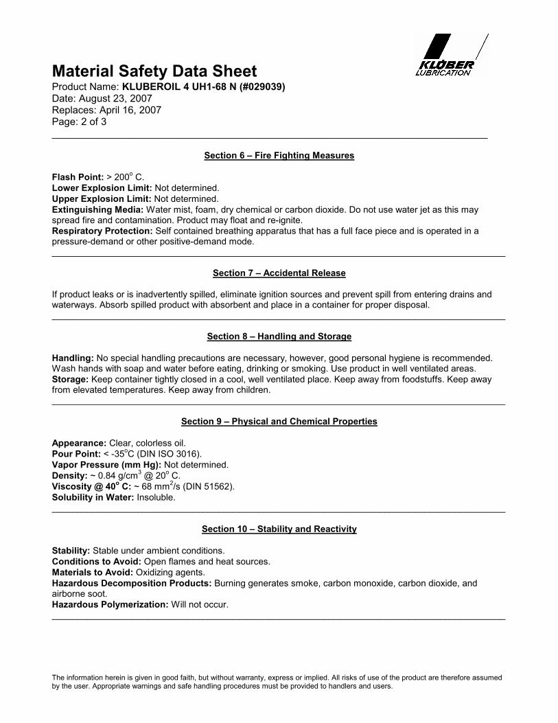
Section 6 – Fire Fighting Measures
Flash Point: > 200o C.
Lower Explosion Limit: Not determined.
Upper Explosion Limit: Not determined.
Extinguishing Media: Water mist, foam, dry chemical or carbon dioxide. Do not use water jet as this may spread fire and contamination. Product may float and re-ignite.
Respiratory Protection: Self contained breathing apparatus that has a full face piece and is operated in a pressure-demand or other positive-demand mode. __________________________________________________________________________________________
Section 7 – Accidental Release
If product leaks or is inadvertently spilled, eliminate ignition sources and prevent spill from entering drains and waterways. Absorb spilled product with absorbent and place in a container for proper disposal. __________________________________________________________________________________________
Section 8 – Handling and Storage
Handling: No special handling precautions are necessary, however, good personal hygiene is recommended. Wash hands with soap and water before eating, drinking or smoking. Use product in well ventilated areas.
Storage: Keep container tightly closed in a cool, well ventilated place. Keep away from foodstuffs. Keep away from elevated temperatures. Keep away from children. __________________________________________________________________________________________
Section 9 – Physical and Chemical Properties
Appearance: Clear, colorless oil.
Pour Point: < -35oC (DIN ISO 3016).
Vapor Pressure (mm Hg): Not determined.
Density: ~ 0.84 g/cm3 @ 20
o C.
Viscosity @ 40o C: ~ 68 mm
2/s (DIN 51562).
Solubility in Water: Insoluble. __________________________________________________________________________________________
Section 10 – Stability and Reactivity
Stability: Stable under ambient conditions.
Conditions to Avoid: Open flames and heat sources.
Materials to Avoid: Oxidizing agents.
Hazardous Decomposition Products: Burning generates smoke, carbon monoxide, carbon dioxide, and airborne soot.
Hazardous Polymerization: Will not occur. __________________________________________________________________________________________
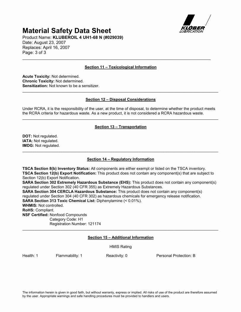
Material Safety Data Sheet
Product Name: KLUBEROIL 4 UH1-68 N (#029039) Date: August 23, 2007 Replaces: April 16, 2007 Page: 3 of 3 ______________________________________________________________________________
The information herein is given in good faith, but without warranty, express or implied. All risks of use of the product are therefore assumed by the user. Appropriate warnings and safe handling procedures must be provided to handlers and users.
Section 11 – Toxicological Information
Acute Toxicity: Not determined.
Chronic Toxicity: Not determined.
Sensitization: Not known to be a sensitizer. __________________________________________________________________________________________
Section 12 – Disposal Considerations
Under RCRA, it is the responsibility of the user, at the time of disposal, to determine whether the product meets the RCRA criteria for hazardous waste. As a new product, it is not considered a RCRA hazardous waste. __________________________________________________________________________________________
Section 13 – Transportation
DOT: Not regulated.
IATA: Not regulated.
IMDG: Not regulated. __________________________________________________________________________________________
Section 14 – Regulatory Information
TSCA Section 8(b) Inventory Status: All components are either exempt or listed on the TSCA inventory.
TSCA Section 12(b) Export Notification: This product does not contain any component(s) that are subject to Section 12(b) Export Notification.
SARA Section 302 Extremely Hazardous Substance (EHS): This product does not contain any component(s) regulated under Section 302 (40 CFR 355) as Extremely Hazardous Substances.
SARA Section 304 CERCLA Hazardous Substance: This product does not contain any component(s) regulated under Section 304 (40 CFR 302) as hazardous chemicals for emergency release notification.
SARA Section 313 Toxic Chemical List: Diphenylamine (< 0.01%).
WHMIS: Not controlled.
RoHS: Compliant.
NSF Certified: Nonfood Compounds Category Code: H1 Registration Number: 121174 __________________________________________________________________________________________
Section 15 – Additional Information
HMIS Rating
Health: 1 Flammability: 1 Reactivity: 0 Personal Protection: B

INSTALLATION AIR CONNECTION • Compressed air connection is located on top of the right support column.
o The machine requires 6-10 bar of dry compressed air. o The pneumatics system is equipped with an air filter, manual shut off valve,
automatic pressure release valve, and pressure switch. Air supply lines containing high levels of moisture need proper drying equipment
to insure proper machine operation and long component life. o The manual shut off valve is utilized as a safety feature for doing maintenance on
the machine. o The automatic pressure release valve will open during an emergency stop, or if
power is turned off. o The pressure switch will shut down the machine if pressure drops below 4-5 bar.
When this occurs, an error message will appear in the alarm screen on the operator interface.
WATER CONNECTION • Cooling water connection is located next to the compressed air connection.
o A pressure switch in the pneumatic panel monitors pressure in the cooling lines. An error message will appear in the alarm screen on the operator interface if
pressure falls below desired limits. • A drain line is also required.
o This connection is made under the seal die top utility block. The fitting matches the inlet fitting. This hose should be routed to the nearest drain, being careful not to route the
hose in the way of any moving parts.

Incoming air connection is made in the top of the support column. As you stand facing the backside, or Utility side of machine, it is the column on the left.

Water into machine: Connection can be made in the top of the column, or on the backside of the sealing station. Based on the configuration of your VC999 Packaging Systems machine, the water in connection will be made at either one of these locations.

Water into machine, connection being made in the top of column, next to the machine air into the machine connection.

Water into machine, shows connection for incoming water into the machine. Water out, show water exiting machine and going to either a water chiller, or to a drain.

INSTALLATION GAS FLUSH CONNECTION (OPTIONAL) • If the machine comes equipped with gas flush, now is the time to make necessary
connections. o A gas accumulator tank is attached under the loading area.
A 1/4” hose connection is supplied for connection to the gas bottle. The gas system requires 2.5 bar of gas pressure.
COVERS & GUARDS • All covers and safety guards should now be replaced.
o All covers are bolted or locked into place. o All safety guards are magnetically locked when in place.
• This should be done before the main power is turned on.


Material Name: Makrolon® GP/OP Article Number: SH005365
Page: 1 of 6 Report Version: 1.0
MATERIAL SAFETY DATA SHEET
1. Product and Company Identification
Product Name: Makrolon® GP/OP Material Number: SH005365 Chemical Family: Thermoplastic Polymer Sheet Chemical Name: Bisphenol A Polycarbonate
2. Hazards Identification
Emergency Overview CAUTION! Color: tint Form: solid sheets Odor: slight. Melted product is flammable and produces intense heat and dense smoke during burning. Irritating gases/fumes may be given off during burning or thermal decomposition. May cause mechanical irritation (abrasion). Contact with hot material will cause thermal burns.
Potential Health Effects Primary Routes of Entry: Inhalation, Skin Contact, Eye Contact Medical Conditions Aggravated by Exposure:
Respiratory disorders
HUMAN EFFECTS AND SYMPTOMS OF OVEREXPOSURE Skin Acute Skin For Product: Makrolon® GP/OP Contact with heated material can cause thermal burns. Eye Acute Eye For Product: Makrolon® GP/OP May cause mechanical irritation. General Effects of Exposure
Sheffield Plastics Inc. 119 Salisbury Road Sheffield, MA 01257 USA
CALL CHEMTREC: (800) 424-9300 INTERNATIONAL: (703) 527-3887
TRANSPORTATION EMERGENCY
NON-TRANSPORTATION Bayer Emergency Phone: (412)-923-1800 Bayer Information Phone: (800) 662-2927

Material Name: Makrolon® GP/OP Article Number: SH005365
Page: 2 of 6 Report Version: 1.0
Acute Effects of Exposure For Product: Makrolon® GP/OP Gases and fumes evolved during the thermal processing or decomposition of this material may irritate the eyes, skin or respiratory tract. Chronic Effects of Exposure For Product: Makrolon® GP/OP Not expected to cause any adverse chronic health effects. Carcinogenicity: No Carcinogenic substances as defined by IARC, NTP and/or OSHA
3. Composition/Information on Ingredients
Hazardous Components This material is not hazardous under the criteria of the Federal OSHA Hazard Communication Standard 29 CFR 1910.1200. OTHER INGREDIENTS Additional types of polycarbonate may be used as necessary to adjust the melt flow rate.
4. First Aid Measures
Eye Contact In case of contact, flush eyes with plenty of lukewarm water. Skin Contact In case of skin contact, wash affected areas with soap and water. Get medical attention if thermal burn occurs. Inhalation If inhaled, remove to fresh air. Ingestion Get medical attention.
5. Fire-Fighting Measures
Suitable Extinguishing Media: water, foam, dry chemical, carbon dioxide (CO2) Special Fire Fighting Procedures Firefighters should be equipped with self-contained breathing apparatus to protect against potentially toxic and irritating fumes. Unusual Fire/Explosion Hazards Toxic and irritating gases/fumes may be given off during burning or thermal decomposition. Dust may form explosive mixtures with air.

Material Name: Makrolon® GP/OP Article Number: SH005365
Page: 3 of 6 Report Version: 1.0
6. Accidental release measures
Spill and Leak Procedures If molten, allow material to cool and place into an appropriate marked container for disposal.
7. Handling and Storage
Storage Temperature:
maximum: 93 °C (199.4 °F) Storage Period Not Established Handling/Storage Precautions Handle in accordance with good industrial hygiene and safety practices. Wash thoroughly after handling. Avoid breathing dust. Further Info on Storage Conditions Protect equipment (e.g. storage bins, conveyors, dust collectors) with explosion vents.
8. Exposure Controls / Personal Protection
Country specific exposure limits have not been established or are not applicable Industrial Hygiene/Ventilation Measures General dilution and local exhaust as necessary to control airborne vapors, mists, dusts and thermal decomposition products below appropriate airborne concentration standards/guidelines, especially during cutting, grinding and high heat operations. Respiratory Protection Although no exposure limit has been established for this product, the OSHA PEL for Particulates Not Otherwise Regulated (PNOR) of 15 mg/m3 - total dust, 5 mg/m3 - respirable fraction is recommended. In addition, the ACGIH recommends 3 mg/m3 - respirable particles and 10 mg/m3 - inhalable particles for Particles (insoluble or poorly soluble) Not Otherwise Specified (PNOS). Hand Protection Wear heat resistant gloves when handling molten material. Eye Protection safety glasses with side-shields. Skin and body protection No special skin protection requirements during normal handling and use. Additional Protective Measures Employees should wash their hands and face before eating, drinking, or using tobacco products. Educate and train employees in the safe use and handling of this product. Purgings should be collected as small flat thin shapes or thin strands to allow for rapid cooling.

Material Name: Makrolon® GP/OP Article Number: SH005365
Page: 4 of 6 Report Version: 1.0
9. Physical and chemical properties
Form: solid Appearance: sheets Color: tint Odor: slight pH: not applicable Melting Point: 220 - 230 °C (428 - 446 °F) Boiling Point/Range: not applicable Flash Point: > 450 °C (> 842 °F) Lower Explosion Limit: Not Established Upper Explosion Limit: Not Established Vapor Pressure: not applicable Specific Gravity: approximately 1.2 Solubility in Water: Insoluble Autoignition Temperature: > 450 °C (> 842 °F) Decomposition Temperature: 380 °C (716 °F) Softening Point: 150 - 160 °C (302 - 320 °F) Bulk Density: 38 - 42 lb/ft3
10. Stability and Reactivity
Hazardous Reactions Hazardous polymerization does not occur. Stability Stable Materials to avoid None known. Conditions to avoid None known. Hazardous decomposition products By Fire and Thermal Decomposition: Carbon Dioxide; Bisphenol A; Phenol; Carbonic Acid, Diphenyl Ester; Carbon monoxide, hydrocarbons, phenol derivatives
11. Toxicological Information
No information available.
12. Ecological Information
No information available.
13. Disposal considerations
Waste Disposal Method Waste disposal should be in accordance with existing federal, state and local environmental control laws.

70 Carlisle Place • Stamford, Connecticut 06902 • (203) 327-6010 • Fax (800) 631-4005 TB05
T E C H N I C A L B U L L E T I N
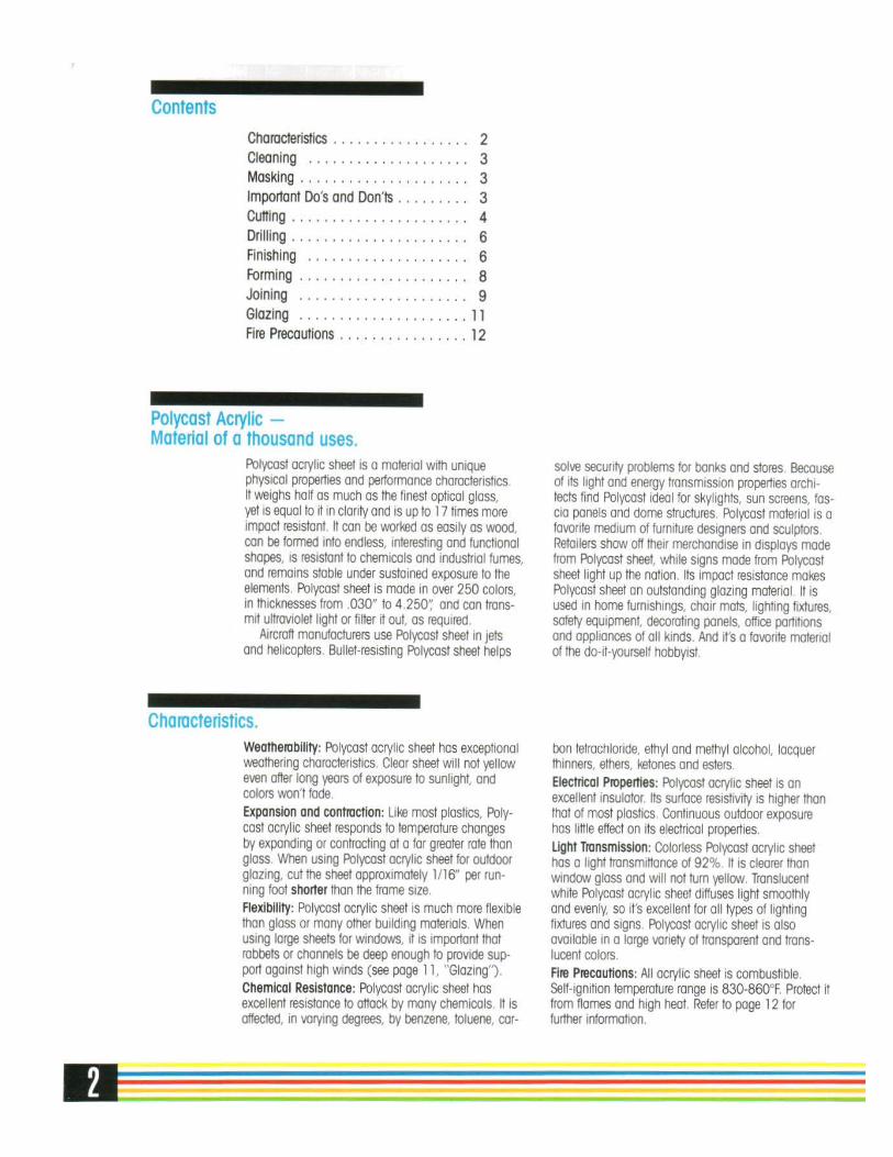
RECOMMENDATIONS FOR CLEANING SPARTECH POLYCAST CELL CAST
ACRYLIC SHEET
For cleaning acrylic sheet, the surface should first be flushed with clean water to remove loose abrasive particles. Then the plastic part or sheet should be gently sponged with a mild detergent/water solution and finally rinsed with clean water. When trying to remove oil or grease from the surface, hexane, mineral spirits (naphtha), kerosene, or 50/50 alcohol/ water solutions (ethanol or isopropyl alcohol) may be used. Apply these solvents with clean absorbent cotton cloths, then rinse with water. If kerosene or mineral spirits are used, it may be necessary to first wash the plastic with soapy water followed by a clean water rinse. Drying can be done with a clean damp chamois, a soft cotton towel, or compressed air can be used to blow the water off. Avoid hard, rough cloths or paper towels since they can put fine scratches on the acrylic surface. Aggressive solvents such as acetone, MEK, lacquer thinner, chlorinated solvents, gasoline, etc., will likely cause the surface of the acrylic to craze, so they should not be used. When these solvents are used, the acrylic surface may not craze immediately, but it may craze later on (sometimes days or weeks later). Window (glass) cleaning compounds usually are not recommended, nor are cleaning products, which contain abrasives. All cleaning materials and cloths must be free of dust, grit or any other foreign particles.

70 Carlisle Place • Stamford, Connecticut 06902 • (203) 327-6010 • Fax (800) 631-4005 TB022
T E C H N I C A L B U L L E T I N
CHEMICAL RESISTANCE OF CELL CAST ACRYLIC SHEET
GENERAL GUIDELINES R RESISTANT: Withstands this substance for long periods and at temperature up to 120oF (49 Celsius). LR LIMITED RESISTANCE: Only resists the action of this substance for short periods at room temperature, suitability for a particular application must be determined. N NOT RESISTANT: Not resistant to this substance.
CHEMICAL CODE CHEMICAL CODE Acetic Acid (5%) R Hydrogen Peroxide (3%) R Acetic Acid (Glacial) N Hydrogen Peroxide (28%) N Acetic Anhydride LR Isooctane R Acetone N Isopropyl Alcohol LR Ammonium Chloride (Saturated) R Kerosene R Ammonium Hydroxide (10%) R Lacquer Thinner N Ammonium Hydroxide (Conc.) R Methyl Alcohol (50%) LR Aniline N Methyl Alcohol (100%) N Battery Acid R Methyl Ethyl Ketone (MEK) N Benzene N Methylene Chloride N Butyl Acetate N Mineral Oil R Calcium Chloride (Sat.) R Naphtha (VM&P) R Calcium Hypochlorite R Nitric Acid (10%) R Carbon Tetrachloride N Nitric Acid (40%) LR Chloroform N Nitric Acid (Conc.) N Chromic Acid (40%) N Oleic Acid R Citric Acid (10%) R Olive Oil R Cottonseed Oil (Edible) R Phenol Solution (5%) N Detergent Solution (Heavy Duty) R Soap Solution (Ivory) R Diesel Oil R Sodium Carbonate (2%) R Diethyl Ether N Sodium Carbonate (20%) R Dimethyl Formamide N Sodium Chloride (10%) R Dioctyl Phthalate N Sodium Hydroxide (1%) R Ethyl Acetate N Sodium Hydroxide (10%) R Ethyl Alcohol (50%) LR Sodium Hydroxide (60%) R Ethyl Alcohol (95%) N Sodium Hypochlorite (5%) R Ethylene Dichloride N Sulfuric Acid (3%) R Ethylene Glycol R Sulfuric Acid (30%) R 2-Ethylhexyl Sebacate R Sulfuric Acid (Conc.) N Formaldehyde (40%) R Toluene N Gasoline (Regular, Leaded) LR Transformer Oil R Glycerine R Trichloroethylene N Heptane R Turpentine LR Hexane (Commercial Grade) R Water (Distilled) R Hydrochloric Acid R Xylene N

SECTION 4 – INTERFACE / TOUCH SCREEN

NOTE: SOME MACHINES MAY HAVE MORE OR LESS PUSHBUTTONS DISPLAYED DEPENDING UPON THE MACHINE OPTIONS.
• CUTTING, SEALING, INDEX, FORMING, PRINTER, & ZIPPER: THESE BUTTONS WILL DISPLAY MANUAL CONTROL SCREEN FOR THAT AREA OF THE MACHINE.
• SEAL DIE TEMP SET: ENTER SEAL DIE TEMPERATURE SETTING (DEG C) • VACUUM PUMP SHUTDOWN DELAY: SET TIME (sec) THAT THE VACUUM PUMP WILL
RUN AFTER END OF AUTO CYCLE BEFORE SHUTTING DOWN. • VACUUM PUMP SERVICE HOURS: VACUUM PUMP HOURS SINCE LAST TIMER RESET • TOTAL MACHINE CYCLES: COUNTS CYCLES MACHINE PERFORMS IN AUTO CYCLE. • TOTAL VACUUM PUMP HOURS: TOTAL HOURS OF VACUUM PUMP OPERATION.
THIS METER IS NOT RESETABLE. • VACUUM PUMP SERVICE HOURS RESET: RESETS VACUUM PUMP SERVICE HOUR
METER. THIS SHOULD BE PRESSED AT THE END OF EVERY VACUUM PUMP SERVICE.
• CROSS CUT MAINT RESET: RESETS CROSS CUT SERVICE HOUR METER. • SET PASSCODE: OPENS PASSWORD SCREEN. THIS SCREEN ALLOWS YOU TO
CHANGE ALL PASSWORDS. YOU MUST HAVE MASTER PASSWORD TO OPEN THIS SCREEN.
• ENTER LICENSE CODE: WILL APPEAR AFTER THE 24th DAY OF THE MONTH. THIS BUTTON WILL OPEN THE PAYMENT CODE SCREEN. OPENING THIS SCREEN WILL ALLOW YOU TO ENTER THE NEXT MONTHS PAYMENT CODE BEFORE THE END OF THE MONTH.
• VACUUM SENSOR CALIBRATE: (OPTIONAL) OPENS VACUUM SENSOR CALIBRATION SCREEN.

NOTE: SOME MACHINES MAY HAVE MORE OR LESS PUSHBUTTONS DISPLAYED DEPENDING UPON THE MACHINE OPTIONS. • AIR SUPPLY DUMP: OPENS MAIN AIR VALVE. IF THIS IS NOT ON YOU CANNOT
OPERATE ANY OF THE AIR POWERED EQUIPMENT. • 1 INDEX: INDEXES FILM CHAIN THE LENGTH SPECIFIED BY “INDEX LENGTH” • CREEP: MOVES FILM CHAIN SLOW • JOG: MOVES FILM CHAIN FAST • ROTARY KNIFE: TURNS ON ROTARY KNIFE MOTOR. • CHAIN LUBE: TURNS ON CHAIN LUBRICATOR. • DANCER ARM EXTEND SEAL: TURNS ON DANCER ARM SENSOR IN SEAL
STATION. • DANCER ARM EXTEND ZIPPER: TURNS ON DANCER ARM SENSOR IN ZIPPER
STATION. • CODE DATE: TURNS ON CODE DATER. • TRIM MOTOR: TURNS ON TRIM REMOVAL MOTOR • LOAD GRID: ACTUATES LOADING GRID • DISCHARG CONVYR: TURNS ON DISCHARGE CONVEYOR • LABEL 1/LABEL 2: TURNS ON DESIGNATED LABELER

NOTE: SOME MACHINES MAY HAVE MORE OR LESS PUSHBUTTONS DISPLAYED DEPENDING UPON THE MACHINE OPTIONS. • AIR SUPPLY DUMP: OPENS MAIN AIR VALVE. IF THIS IS NOT ON YOU CANNOT
OPERATE ANY OF THE AIR POWERED EQUIPMENT. • DIE CLOSE: CLOSES FORM DIE • DIE OPEN: OPENS FORM DIE • FORM DIE LOCK: (OPTIONAL) CLOSES DIE LOCKS • FORM VACUUM: OPENS FORM VACUUM VALVE • FORM AIR: OPENS POSITIVE FORM AIR VALVE • SEAL VACUUM PUMP: TURNS ON SEAL VACUUM PUMP • FILM HEAT AIR: OPENS FILM HEATING VALVE • FILM HEAT VACUUM: OPENS FILM HEATING VACUUM VALVE • FORMING PUMP: TURNS ON FORM VACUUM PUMP • FORM VENT: OPENS FORM DIE VENT • HEAT VENT: OPENS PREHEAT DIE VENT • PLUG ASSIST UP: ACTUATES PLUG (FILLER) CYLINDER UP • 1 INDEX: INDEXES FILM CHAIN THE LENGTH SPECIFIED BY “INDEX LENGTH” • CREEP: MOVES FILM CHAIN SLOW

NOTE: SOME MACHINES MAY HAVE MORE OR LESS PUSHBUTTONS DISPLAYED DEPENDING UPON THE MACHINE OPTIONS. • AIR SUPPLY DUMP: OPENS MAIN AIR VALVE. IF THIS IS NOT ON YOU CANNOT
OPERATE ANY OF THE AIR POWERED EQUIPMENT MANUAL OPERATION • DIE CLOSE: CLOSES FORM DIE • DIE OPEN: OPENS FORM DIE • 1 INDEX: INDEXES FILM CHAIN THE LENGTH SPECIFIED BY “INDEX LENGTH” • DIE LOCKS: (OPTIONAL) CLOSES DIE LOCKS • VACUUM BALANCE: APPLIES VACUUM TO BALANCE SIDE OF SEAL DIE • VACUUM PACKAGE: APPLIES VACUUM TO PACKAGE OF SEAL DIE • CREEP: MOVES FILM CHAIN SLOW • VENT BALANCE: OPENS SEAL DIE VENT ON BALANCE SIDE OF SEAL DIE • VENT PKG BOTTOM: OPENS SEAL DIE VENT ON PACKAGE SIDE OF SEAL DIE • SEAL: ACTUATES SEAL PLATE • SEAL VACUUM PUMP: TURNS ON SEALING VACUUM PUMP • SEAL VACUUM PUMP #2: (OPTIONAL) TURNS ON SECOND SEALING VACUUM
PUMP • GAS FLUSH: OPENS GAS FLUSH VALVE • SEAL DIE LOCK: (OPTIONAL) CLOSES DIE LOCKS • FORMING PUMP: TURNS ON FORMING VACUUM PUMP

NOTE: SOME MACHINES MAY HAVE MORE OR LESS PUSHBUTTONS DISPLAYED DEPENDING UPON THE MACHINE OPTIONS. • AIR SUPPLY DUMP: OPENS MAIN AIR VALVE. IF THIS IS NOT ON YOU CANNOT
OPERATE ANY OF THE AIR POWERED EQUIPMENT MANUAL OPERATION • 1 INDEX: INDEXES FILM CHAIN THE LENGTH SPECIFIED BY “INDEX LENGTH” • CREEP: MOVES FILM CHAIN SLOW • TRIM CAN: ACTUATES TRIM CAN • HOLE PUNCH: ACTUATES HOLE PUNCH • GUILOTINE UPPER POSITION CYL: (OPTIONAL) SHIFTS MOVING GUILOTINE TO
FIRST POSITION • GUILOTINE LOWER POSITION CYL: (OPTIONAL) SHIFTS MOVING GUILOTINE TO
SECOND POSITION • ROTARY KNIFE: TURNS ON ROTARY KNIFE • CROSS CUT 1-4: ACTUATES CROSS CUT KNIFE • GUILOTINE 1-4 TOP CYLINDER: ACTUATES GUILOTINE TOP CYLINDER • GUILOTINE 1-4 BOTTOM CYLINDER: ACTUATES GUILOTINE BOTTOM CYLINDER • EURO PUNCH 1: ACTUATES FIRST EURO PUNCH CYLINDER • EURO PUNCH 2: ACTUATES SECOND EURO PUNCH CYLINDER

PASSWORD SETUP ACCESS: OPENS NUMERIC KEYPAD THAT WILL ALLOW YOU TO TYPE IN A NEW MASTER PASSWORD. THIS IS THE PASSWORD YOU NEED TO OPEN THIS SCREEN. IF YOU FORGET THIS PASSWORD THEN YOU WILL NOT BE ABLE TO OPEN THIS SCREEN AGAIN. STORE THIS CODE IN A SAFE LOCATION. THIS PASSWORD WILL PERMIT ACCESS TO ALL PRODUCT SETTINGS AND MAINTENACE SCREENS. MAINTENANCE CODE (1-3) : OPENS NUMERIC KEYPAD THAT WILL ALLOW YOU TO TYPE IN A NEW MAINTENACE PASSWORD. THESE PASSWORDS WILL PERMIT ACCESS TO ALL PRODUCT SETTINGS AND MAINTENACE SCREENS. PRODUCT SETTING CODE (1-3) : OPENS NUMERIC KEYPAD THAT WILL ALLOW YOU TO TYPE IN A NEW PRODUCT SETTING PASSWORD. THESE PASSWORDS WILL PERMIT ACCESS TO ALL PRODUCT SETTINGS, BUT NO ACCESS TO MAINTENACE SCREENS. OPERATOR: THIS BUTTON WILL OPEN THE OPERATOR SCREEN.

SECTION 5 - MAINTENANCE & INSPECTION SCHEDULE

INSPECTION SCHEDULE DAILY INSPECTIONS
• Remove any film build up in chain grippers, around sprockets and in the chain guides. • Remove debris in the form and seal die bottoms. • Wear protective gloves to clean and inspect the cutting blades.
o Clean with anti-corrosive agents and lubricate with non-acid oils. • Clean spindle threads with a wire brush.
o Threads will have build-up of cardboard shavings from film core. • Replace any damaged grippers in film transport chain. • Examine all safety guards and emergency stops for damage.
o Repair or replace as needed • Examine radius plates for debris or damage.
o Make sure all vent holes are clear. • Clean the machine per your company standards.
o Do not use corrosive or acidic agents. • Dry the machine by hand or with compressed air to remove standing water. • Lubricate all metal surfaces with a light coating of mineral oil or equivalent.
WEEKLY INSPECTIONS
• Examine seal gasket(s) and all o-ring seals in the form and seal tooling. • Inspect for damage or contamination on the form heat plate, seal plate(s) and the seal die top
cavity. o Clean as needed making sure all vent holes are clear on the form heat plate and there is
no contamination inside the seal die top cavity. • Inspect and clean the seal die bottom for pin gas applications. • Replace cutting blades as needed using protective gloves. • Test the safety fault indicators on the machine when each guard is removed. • Make sure the machine cycle is stopped when each guard is removed. • Test emergency stop switches.
o The machine cycle will stop immediately when pressed. • Clean and lubricate the gripper chain. • Check oil level in the vacuum pump. • Perform a vacuum test on the seal die chamber. • Make sure the film tension systems and the film tracking adjustments are functioning
properly.
MONTHLY INSPECTIONS
• Tension chain by using chain tensioners (see exploded view). o Remove a link if necessary.
• Check lubricator in the pneumatic cabinet for the low pressure manifold. o Examine oil level and oiling rate. o Oilier should give one drop in 3 minutes (open approximately ¾ turn).
• Check PLC battery o The PLC battery indicator light is located on the front of the PLC. If the red light is on, the
battery is low and needs to be replaced o The battery is located on top of the PLC under a small cover approx. 40mm long 15mm
wide o When the battery is unplugged you have 20 seconds to reconnect the new battery before
you lose stored parameters. • Grease both chain drive shaft bearing zerts as well as single zert on non-form film unwind.

INSPECTION SCHEDULE 6-MONTH INSPECTION
• Visually inspect electrical panel for loose wires, terminals, etc. • Examine all hoses for air leaks. • Change oil in vacuum pump. • Check and clean Vacuum/Vent valves. Rebuild as necessary • For routine maintenance on the main drive gearbox, see below
Please see next page for Series B06 gearbox maintenance and approved lubricants.

Series B Approved Lubricants6HULHV%XQLWVDUHIDFWRU\¿OOHGZLWKDKLJKTXDOLW\V\QWKHWLFOXEULFDQW7KH\DUH³/XEULFDWHGIRU/LIH´DQGUHTXLUHQRURXWLQH maintenance in service.
,QWKHHYHQWRIDPDMRURYHUKDXOLQYROYLQJVWULSGRZQDQGUHDVVHPEO\RIWKHJHDUXQLWUHIHUWR7DEOHIRUDOLVWRIDSSURYHG OXEULFDQWV/XEULFDQWTXDQWLWLHVDUHJLYHQLQ7DEOHV
Table 1 Approved Lubricants
Type H 3RO\DOSKDROH¿QEDVHGV\QWKHWLFOXEULFDQWV7KHVHOXEULFDQWVDUHVXLWDEOHIRUDPELHQWWHPSHUDWXUHVRIo)WRo)o&WRo&RXWVLGHRIWKLV please contact our Application Engineers
6833/,(5 /8%5,&$17 5$1*(
*5$'(+ 2,/6833/,(56¶
&255(6321',1* '(6,*1$7,216
&KHYURQ7H[DFR &ODULW\6\QWKHWLF302 ([[RQ0RELO&RUSRUDWLRQ 6+&6HULHV
DANGER 1XPEHUVLQEUDFNHWVLQGLFDWHUHFRPPHQGHGPLQLPXPRSHUDWLQJWHPSHUDWXUHLQoF.7KHXQLWPXVWQRWUXQEHORZWKLVWHPSHUDWXUH
&219(56,217$%/( Table 2 Lubricant Quantities (liters) /LWHUVWR86JDOORQV OLWHUV [ $SSOLFDEOHIRUDOOPRXQWLQJSRVLWLRQV /LWHUVWR,PSHULDOJDOORQV OLWHUV [
02725,=(' RU5('8&(5
81,76,=( % % % % % % % % %
2LO&DSDFLW\ 4XDUWV /LWHUV
Table 3 Double Reduction Lubricant Quantities
$SSOLFDEOHIRUDOOPRXQWLQJSRVLWLRQV
8QLW Size
% % % % % %
3ULPDU\ Secondary 3ULPDU\ Secondary 3ULPDU\ Secondary 3ULPDU\ Secondary 3ULPDU\ Secondary 3ULPDU\ Secondary 4XDUWV
/LWHUV
6DOHV -25- 6DOHV)D[
7UDYHUVH&LW\0,

ANNUAL INSPECTION
Remove chains and switch to opposite side of machine for operation. o (Refer to Chain Installation for proper instruction)
Vacuum pump
Change initial factory oil after 500 hours of service or 5 weeks. Recommended oil is ISO VG-100
o Or SAE equivalent of 33W non-detergent. o 90-weight oil is not recommended.
Change oil every 500 hours of service. If severe operating conditions exist the time interval must be shortened.
o Pump capacity is approximately 6 liters. o Pump manufacturer recommends the following oil brands:
BP Energol RC 100 EssoTeresso 100 Mobil DTE Oil extra heavy Shell Corena Oil P 100 Or equivalent oils from other manufacturers.
Regularly clean the inlet filter by washing and/or blowing it out with compressed air. o Replace the inlet filter if it is damaged or completely contaminated.
Changing the exhaust filter elements is recommended every 2000 operating hours. o It is not possible to clean these elements.

MAINTENANCE DIE LOCK ADJUSTMENT The die lock adjustment is set at the factory. If the die lock needs adjusted for any reason; follow these instructions:
Contact wheel Form Station Seal Station
Back Side View of Die Lift Assembly
• When die bottom is in up position, operate the die locks in and out of lock position to
see if there is any interference between wear pad and die lock. • Remove the die top. • If die locks are not going to the full locked position then the die lock mounts need to
be lowered. • If die locks are going to the full locked position without touching the wear pad, then
the die lock mounts need to be raised.

MAINTENANCE
• Each die lock mount will need to be adjusted independent of the other. • Each time the die lock mount adjustment screws are adjusted; the mounting bolts will
need to be loosened, separate the die lock mount from the utility block and retightened the mounting bolts.
o To retighten mounting bolts, hold down on the die lock to ensure it is in the proper position.
• A ¼ turn of the die lock mount adjustment screw is equal to 0.33mm (0.013 inches). • Adjust die locks until they move in and out of position freely but still make contact
with the wear pad when in the locked position. o The die lock contact wheel must be able to be rotated by hand and in contact of the
wear pad when engaged for proper clearance. • Place the die top back on the machine and close the die. • Operate the die locks to the locked position to check for correct adjustment.
Note: The die lock mounts are not shown for clarity.

MAINTENANCE Top Film Tension Adjustment The top film dancer arm is set at the factory to keep tension on the top film during operation. Proper adjustments of the sensor target and flow control are critical for accurate reading of registered film. If during operation the top film does not keep tension, adjustments must be made to keep tension on the film. • If the cylinder is fully extending before the brake is engaging, the sensor target can
be adjusted to actuate the brake sooner. To adjust the sensor target, loosen the screw and locate target so during machine operation the dancer arm cylinder does not fully extend or fully retract.
• If the dancer arm air cylinder is actuating too quickly and fully extends after the
sensor target is properly adjusted, the flow control on the manifold block must be adjusted to slow operation. If the air cylinder is actuating too slowly and not causing the brake to engage before the next index, the flow control on the manifold block must be adjusted to quicken operation.
INSTALLATIONAND
OPERATING MANUAL
R5 SeriesCurrent Models 0025, 0040, 0063, 0100 and 0250
Single Stage Rotary Vane Vacuum Pumps

TTABLE OF CONTENTSABLE OF CONTENTS
Page
GENERAL 2
Identification 2Operating Principles 2
1.0 INSTALLATION 2
1.1 Unpacking 21.2 Location 21.3 Power Requirements 21.4 Vacuum Connections 31.5 Oil Filling 3
2.0 OPERATION 4
2.1 Start-up 42.2 Gas Ballast 42.3 Process Gas 42.4 Stopping Pump 52.5 Water-Cooled Pumps (optional) 52.6 Oxygen Service Pumps 5
3.0 MAINTENANCE 5
3.1 Pump Oil 63.1.1 Oil Level 63.1.2 Oil Type and Quantity 63.1.3 Oil and Filter Change 63.2 Automotive-Type Oil Filter 73.3 Exhaust Filter 73.4 Inlet Flange 73.5 Vacuum Inlet Filter (optional) 83.6 Maintenance Chart 83.7 Overhaul Kit/Filter Kit 8
4.0 TROUBLESHOOTING 8
5.0 LIMITED STANDARD WARRANTY 11
Technical, Motor and Electrical Data 12Parts List 13Illustration of R5 0025/0040 14Illustration of R5 0063/0100 15Illustration of R5 0250C 16Busch, Inc. Factory Service Center 17
We reserve the right to change the product at any time without any form of notification. The information in this publicationis accurate to the best of our ability at the time of printing. Busch, Inc. will not be responsible for errors encountered whenattempting to perform tasks outlined in this publication which is copyright protected.
1

GENERAL
Identification
For model identification, see the nameplate mounted onthe side of the exhaust box.
This manual is written to cover RA and RC versions ofmodels 0025, 0040, 0063, 0100, and 0250 with a "C" or "E"appearing as the seventh character in the model type num-ber stamped into the nameplate. For example it wouldappear as follows:
RAXXXX - CXXX - XXXX
When ordering parts, it is helpful to include the identifica-tion code stamped into the side of the cylinder as well asthe serial number from the nameplate.
Operating Principles
All reference (Ref. XX) numbers listed in the text and onillustrations throughout this manual are related to the draw-ings and parts list near the center of this publication.
All R5 Series, Single Stage, Rotary Vacuum Pumps aredirect-driven, air-cooled, oil-sealed rotary vane pumpswhich operate as positive displacement pumps. They con-sist of a rotor positioned eccentrically in a cylindrical stator(see Fig. 1). When the rotor spins, centrifugal force push-es the vanes, which glide in the slots, towards the wall ofthe cylinder. The rotor has three vanes which divide thepump chamber into three segments. The gas to bepumped enters at the inlet port, passes through the inletscreen and the open anti-suck-back valve into the pumpchamber. As the rotor rotates, the inlet aperture is closed,the gas is compressed and forced out through one-wayvalves between the pump cylinder and the exhaust box.This operation is repeated three times each revolution.
1.0 INSTALLATION
1.1 Unpacking
Inspect the box and pump carefully for any signs of dam-age incurred in transit. Since all pumps are ordinarilyshipped FOB our factory, such damage is the normalresponsibility of the carrier and should be reported to them.
Remove the nuts from the bottom of the box/crate and pullthe pump out of the container, then unscrew the studs from
the bottom of the rubber feet.
The inlet port of the pump is covered with a plastic capprior to shipment to prevent dirt and other foreign materialfrom entering the pump. Do not remove this cover until thepump is actually ready for connection to your system.
1.2 Location
The pump must be installed in a horizontal position on alevel surface so that the pump is evenly supported on itsrubber feet. Allow sufficient air space between the pumpand any walls or other obstructions; adequate ventilationmust be provided for the fans on the pump and motor (i.e.,do not locate the pump in a stagnant air location).
Whenever the pump is transported, be sure to drain the oilprior to shipping to avoid vane breakage when restartingthe pump.
Do not tip the pump over if it is filled with oil.
Locate the pump for easy access to the oil sight glass (Ref.83) in order to inspect and control the oil level properly.Allow clearance at the exhaust flange area to provide serv-ice access to the exhaust filters.
1.3 Power Requirements
The schematic diagram for the electrical connection islocated in the junction box or on the nameplate of the pumpmotor.
The motor must be connected according to the electricalcodes governing the installation. The power supply mustbe routed through a fused switch to protect the motoragainst electrical or mechanical overloads. The motorstarter has to be set consistent with the motor current list-ed on the motor nameplate.
If the pump is supplied with a manual motor starter, it ispreset at the factory in accordance with the customer’sspecification. For other voltage requirements, contact thefactory for motor and/or starter information.
Note: See the motor manufacturer’s manual for start-upmaintenance of the motor.
Correct direction of rotation is marked by an arrow on themotor fan housing and is counterclockwise when looking atthe motor from the motor's fan side.
All R5 series pumps are designed to handle air. Vapor inthe air stream can be tolerated when the pump is operat-ed within certain operating parameters as defined byBusch, Inc. Engineering (see Section 2.2 - Gas Ballast).When you desire to use the pump on an air stream thatcontains vapors, contact Busch, Inc. Engineering for oper-ating recommendations; otherwise, the warranty could bevoid.
2
CAUTION: After the electrical connection has beenmade, but before the pump is filled with oil, the rota-tion of the motor must be checked. Open the inlet portand jog the motor briefly to make sure rotation is cor-rect. If it runs backwards and if it is wired three phasepower, reverse any two leads of the three at the powerconnection.

1.4 Vacuum Connections
Use a line size to the vacuum system that is at least aslarge as that of the pump inlet. Smaller lines will result inlower pumping speeds than the rated values.
Install a drip leg and drain on the vertical pipe near thepump inlet. Drain the drip leg often to prevent condensa-tion from entering the pump.
If more than one vacuum pump or a receiver tank is con-nected to a common main line, each pump should have itsown manual or automatic operated shut-off valve or posi-tive action check valve. The built-in anti-suck-back valveshould not be used as a shut-off valve for the vacuum sys-tem.
Remove the plastic protective cap from the inlet port priorto connection of the pump to the system. Vertical connec-tion of the vacuum line can be made directly to the pumpinlet (Ref. 260).
The type and size of the inlet connections of the R5 Seriespump is shown in the TECHNICAL DATA page 13.
If the gas that is pumped contains dust or other foreignsolid particles, a suitable (10 micron rating or less) inlet fil-ter should be connected to the inlet port. Consult the fac-tory for recommendations.
1.5 Oil Filling
The pump is shipped without oil. After level installation,and after correct rotation has been established and withthe pump switched “off” and secured against accidentalstartup, fill the pump with the recommended vacuum oilthrough the oil filling port (Ref. 88), observing the “MAX”and “MIN” position at the oil sight glass (Ref. 83).
Non-detergent oil should be used. Do not use detergentmotor oil as additives in detergent oil will plug exhaust fil-ter elements and shorten their life.
It is recommended that Busch R500 Series oil be used toreceive the best performance from your vacuum equip-ment. R500 Series oil is a high quality vacuum oil whichwill give longer running time between oil changes, will pro-
CAUTION: The built-in anti-suck-back valve is not pos-itive action; do not use it as a system check valve.
3
Exhaust
InletExhaust filter
Gas ballast(RA)
Rotor
Anti-suckback valve
Inlet screen
Vane
Automotive typespin-on filter Main oil feed line
Exhaust valve (RA)
Oil return valve (RA)
Oil sight glass
Oil return line toinlet (RC)
Fig. 1 - Basic R5 Pump

vide better lubrication at high operating temperatures, andwill prolong the life of exhaust filter elements. This oil canbe obtained directly from Busch, Inc. in Virginia Beach,Virginia.
The strict use of Busch oils and parts from the day of pur-chase can extend the standard warranty to three years.Contact Busch, Inc. in Virginia Beach, Virginia for details.Refer to page 12 for the standard warranty.
For general applications, use R530 in most models cov-ered by this manual. Use R590 or R570 in pumps that areoperated in high ambient temperatures (above 90°F) orwhen the oil carbonizes (turns black) before the changeinterval. Use R590 or R570 on 0250 pumps. Contact thefactory for recommendations when using other oils.
The TECHNICAL DATA chart on page 13 gives the approx-imate quantities of oil required for each pump. The oilcapacity chart should only be used as a guide, since oilcapacity may be slightly lower, depending on whether thepump was filled previously, and whether all componentssuch as oil filter, oil lines, etc., were allowed to completelydrain. Use only the sight glass reading for proper level.Never overfill!
For ambient operating temperatures lower than 41°F, useBusch R580 synthetic oil. If this does not help (where thepump has difficulty starting due to high oil viscosity) contactthe factory in Virginia Beach, Virginia.
Replace the oil fill plug (Ref. 88/90), making sure that thegasket (Ref. 89) is in place and properly seated andsecured. Some pumps are equipped with an exhaust pres-sure gauge as an integral part of the oil fill plug. Switch thepower back into the “on” position.
2.0 OPERATION
2.1 Start-up
Check rotation of the motor as described in Section 1.3 -Power Requirements.
Fill the pump with oil as described in Section 1.5 - OilFilling.
Start the pump and immediately close the inlet. Run thepump for a few minutes before checking the oil level again.With the pump shut off, the oil level should be visible in theoil sight glass (Ref. 83), between the “MIN” and “MAX”mark.
Add oil, if necessary, but only add it when the pump hasbeen shut off and the circulating oil has had sufficient time
to return to the oil sump.
Note: The oil separated by the exhaust filter element formsdroplets on the outside of the exhaust filter which collect ata low point in the upper half of the exhaust box. From therethe collected oil is drained back to the oil sump via an oilcheck valve (Ref. 275) which opens on R5 RA ModelPumps when the pump is shut off. It is necessary to shutoff the RA model pumps after every 8 hours of operation toallow the check valve to open. If the pump is not shut offafter this time period, it is possible to starve the pump of oilsince the oil is not allowed to drain back into the oil sumpand/or oil droplets may be blown out of the exhaust. If thepump is operating at high pressure it may be necessary toshut it down sooner than 8 hours.
On R5 (Standard) RC Model Pumps, the collected oil isdrawn continuously during operation of the vacuum pumpto the inlet flange (Ref. 260) via the oil return line (Ref.290). The oil return line is connected directly to the area ofthe exhaust box, downstream of the exhaust filter, which isat atmospheric pressure. Therefore, a constant amount ofair is sucked into the pump which is an additional reasonthat the R5 Standard Series Pumps do not achieve as lowa vacuum as the R5 Series Super Vacuum Pumps. RCmodel pumps can run continuously without having to shutthem off for the oil to drain back.
2.2 Gas Ballast
All RA Series pumps are equipped with a gas ballast valve.The gas ballast valve (Ref. 440) is located between theinlet port and the exhaust box. RA Series pumps up to size0100 are equipped with a permanent gas ballast whichcannot be shut off unless the sintered filter is removed andthe orifice plugged. Larger pumps are equipped with anadjustable gas ballast valve.
The adjustable gas ballast valve should normally be leftopen. Its primary function is to prevent water vapor fromcondensing in the pump. Condensation causes emulsifi-cation of the oil, loss of lubricity, and possible rotor seizure.
2.3 Process Gas
The R5 series pumps are designed to pump air and are notintended for use when water vapor is being pumped. Insome applications, when the quantity of the water vapor ismoderate, R5 pumps have been used with good results.On the occasions, the pump is run until it is up to operatingtemperature before it is allowed to pump the process gas.The pump is also operated for a period of time off processand on air (to clear it of process gas) before it is shut down.This operating technique prevents the vapor from con-densing in the pump. Before attempting to pump a gasladen with water vapor, contact Busch Engineering foradvice.
4
WARNING: Keep the oil fill plug tight as pressure inthe exhaust box could cause bodily injury if the plugis blown out. Do not fill/add the pump with oil throughthe exhaust/inlet ports as there is danger of breakingthe vanes!
2.4 Stopping Pump
To stop the pump, turn off the power. The pump has a built-in anti-suck-back valve (Ref. 251 thru 255) to prevent thepump from rotating backwards when it is shut off.
Install an automatic operated valve (such as a check valve)in front of the pump, if more than one pump is pumping onthe same line or if there is a sufficient volume of vacuum inthe system to cause the pump oil to be drawn into the pip-ing when that pump is shut down.
All R5 Series pumps are vented internally to atmosphericpressure through venting holes which are next to theexhaust valve assembly.
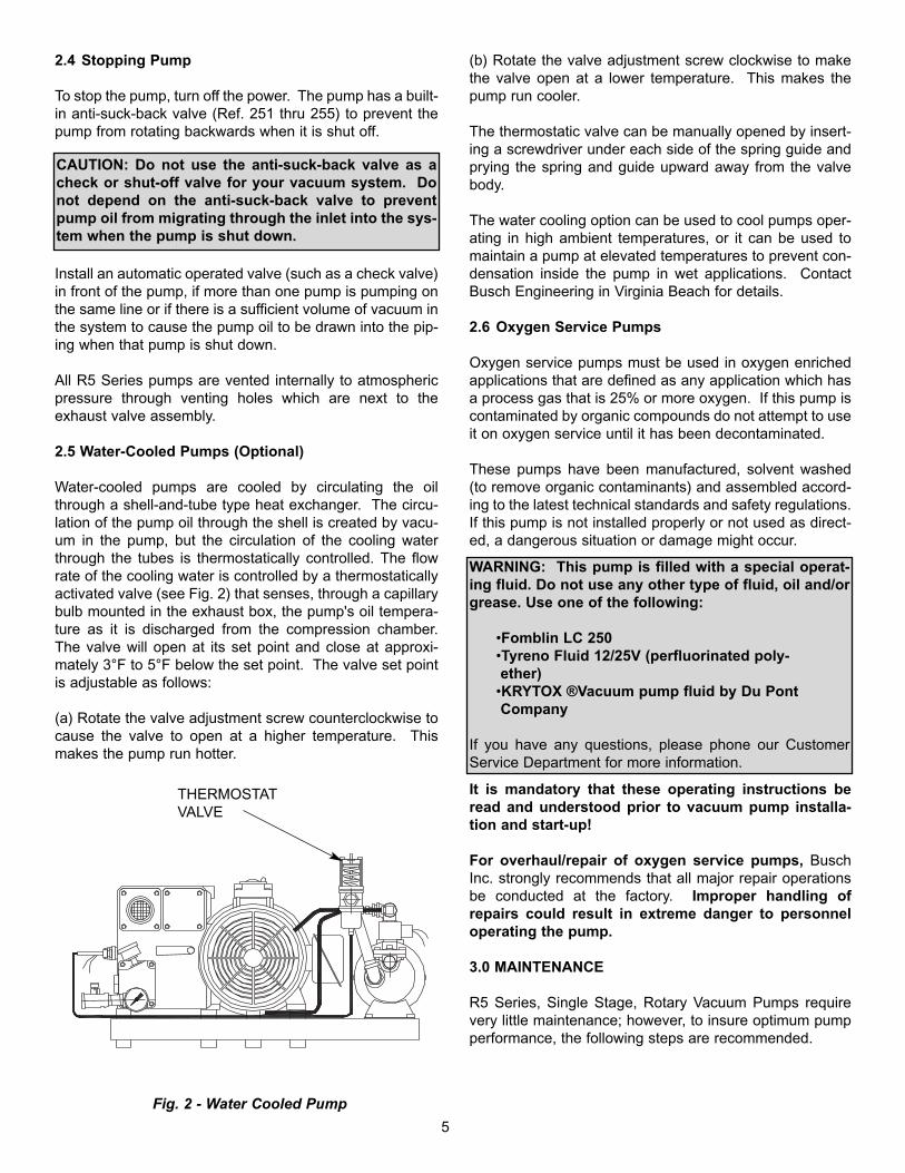
2.5 Water-Cooled Pumps (Optional)
Water-cooled pumps are cooled by circulating the oilthrough a shell-and-tube type heat exchanger. The circu-lation of the pump oil through the shell is created by vacu-um in the pump, but the circulation of the cooling waterthrough the tubes is thermostatically controlled. The flowrate of the cooling water is controlled by a thermostaticallyactivated valve (see Fig. 2) that senses, through a capillarybulb mounted in the exhaust box, the pump's oil tempera-ture as it is discharged from the compression chamber.The valve will open at its set point and close at approxi-mately 3°F to 5°F below the set point. The valve set pointis adjustable as follows:
(a) Rotate the valve adjustment screw counterclockwise tocause the valve to open at a higher temperature. Thismakes the pump run hotter.
(b) Rotate the valve adjustment screw clockwise to makethe valve open at a lower temperature. This makes thepump run cooler.
The thermostatic valve can be manually opened by insert-ing a screwdriver under each side of the spring guide andprying the spring and guide upward away from the valvebody.
The water cooling option can be used to cool pumps oper-ating in high ambient temperatures, or it can be used tomaintain a pump at elevated temperatures to prevent con-densation inside the pump in wet applications. ContactBusch Engineering in Virginia Beach for details.
2.6 Oxygen Service Pumps
Oxygen service pumps must be used in oxygen enrichedapplications that are defined as any application which hasa process gas that is 25% or more oxygen. If this pump iscontaminated by organic compounds do not attempt to useit on oxygen service until it has been decontaminated.
These pumps have been manufactured, solvent washed(to remove organic contaminants) and assembled accord-ing to the latest technical standards and safety regulations.If this pump is not installed properly or not used as direct-ed, a dangerous situation or damage might occur.
It is mandatory that these operating instructions beread and understood prior to vacuum pump installa-tion and start-up!
For overhaul/repair of oxygen service pumps, BuschInc. strongly recommends that all major repair operationsbe conducted at the factory. Improper handling ofrepairs could result in extreme danger to personneloperating the pump.
3.0 MAINTENANCE
R5 Series, Single Stage, Rotary Vacuum Pumps requirevery little maintenance; however, to insure optimum pumpperformance, the following steps are recommended.
5
Fig. 2 - Water Cooled Pump
THERMOSTATVALVE
WARNING: This pump is filled with a special operat-ing fluid. Do not use any other type of fluid, oil and/orgrease. Use one of the following:
•Fomblin LC 250•Tyreno Fluid 12/25V (perfluorinated poly-ether)
•KRYTOX ®Vacuum pump fluid by Du Pont Company
If you have any questions, please phone our CustomerService Department for more information.
CAUTION: Do not use the anti-suck-back valve as acheck or shut-off valve for your vacuum system. Donot depend on the anti-suck-back valve to preventpump oil from migrating through the inlet into the sys-tem when the pump is shut down.

3.1 Pump Oil
3.1.1 Oil Level
With the pump installed relatively level, make sure thatthere is sufficient clean oil in the pump. The oil level shouldbe observed on a daily basis and/or after 8 hours of oper-ation and should be replenished if it drops below the 1/4mark on the oil sight glass.
On RA Series pumps you must first shut the pump off inorder to let the oil flow back into the oil sump prior to check-ing the sight glass. Allowing insufficient time for the oil todrain back into the sump on RA Series pumps prior toadding oil could result in overfilling.
Oil level readings should be done only when the pump isturned off. Oil can be added to the oil fill port (Ref. 88) ifthe pump is shut off and the circulating oil has sufficienttime to return to the oil sump. The oil might appear to befoamy, which is a normal phenomenon with aerated oil.
Under normal circumstances, it should not be necessary toadd or drain oil from the pump between recommended oilchanges.
A significant drop in oil level means there is an oil leak orthat an exhaust filter is broken, and the pump should besmoking excessively. It is normal for the oil to be foamyand light in color in an operating pump. However, if the oilis milky colored, it is an indication that water is present inthe oil. Normally, by operating the pump for an extendedperiod, with the inlet suction blanked off and the gas ballast(Ref. 440) open on RA pumps, the water will be purgedfrom the oil. If the oil is dark colored, it is contaminated orcarbonized and must be changed. Depending on theseverity of the contamination, a thorough flushing may berequired. Contact the factory for flushing oil (Busch R568)and instructions.3.1.2 Oil Type and Quantity
See Section 1.5 - Oil Filling - for details on oil type andquantity.
3.1.3 Oil and Filter Change
Check the oil for contamination on a weekly basis by shut-ting the pump off and draining some of the oil into a smallglass or a similar transparent container through the oildrain port (Ref. 95).
Oil life is dependent upon the conditions to which it isexposed. A clean, dry air stream and an oil operating tem-perature under 210°F are ideal conditions. When usingR530 (hydrocarbon oil) it is recommended that oil changesare made every three (3) to four (4) months or 500 to 750hours of operation, or as necessary if high heat is contam-inating the oil. The use of Busch R570 (synthetic) or R590(semi-synthetic) oil may significantly extend the operatinghours between oil changes under ideal conditions; howev-er, you may need to flush out the pump before changing.Contact the factory Service Department for advice. Oilsamples should be taken regularly when exceeding the500-750 hour recommendation.
Excessive Heat
When the pump is subjected to operating conditions thatwill cause the oil to be heated above 210°F, the oil will car-bonize and become contaminated after a relatively lownumber of operating hours. The higher the temperature,the quicker the oil becomes contaminated. If the oil tem-perature is too severe, Busch R570 (synthetic) or R590(semi-synthetic) oil should be used to withstand the elevat-ed temperatures. If synthetic oil is used, the pump shouldbe flushed with Busch R568 oil. Contact the factory forinstructions on the flushing procedure. Auxiliary oil coolingis the most practical approach to a severe heating problem.
Contaminated Air Stream
When the air stream contains solids and/or liquid that con-taminate the oil, it must be changed more often. If the airstream contains a small percentage of contaminatesand/or they are slightly aggressive* (mild acids, etc.), syn-thetic oil, such as Busch R570, will resist breakdown betterthan the standard Busch R530. The solution is to install afilter or knock-out pot to keep the contaminates out of thepump.
*Process air streams with a large percentage of contaminatesand/or are more than slightly aggressive must use a chemicalduty pump.
Oil change intervals can only be established by experiencewith the pump operating in the actual conditions (see pre-vious paragraph for some of the conditions). Develop theoil change interval by periodically checking an oil sampleremoved from the pump. When the oil sample has becomedark in color (from solids and carbonized particles) or ismilky looking (from water), it is time to discard it. As men-tioned before, a thorough flushing may be required.
CAUTION: When changing the oil and filters, it may benecessary to flush the pump to remove any build-up ofdegraded oil from the sumps, oil lines, radiators, etc.to ensure proper oil flow through the pump. Reducedoil flow, especially through radiators and coolingcoils, can cause mechanical damage or extreme over-heating which could cause the oil vapors to ignite.
6
CAUTION: Do not add oil while the pump is runningsince hot unfiltered oil vapor may escape through theoil fill port.
CAUTION: Insufficient oil quantity in the pump has thepotential, under certain conditions, to lead to self-igni-tion of the remaining oil in the pump.

3.2 Automotive-Type Oil Filter
The pump is equipped with an automotive-type oil filter(Ref. 100). When replacing the automotive-type oil filter,use only a Busch genuine filter.
Note: Make sure to tighten the Busch oil filter securelyagainst the aluminum sealing surface so that leaks will notoccur.
3.3 Exhaust Filter
Every nine (9) to twelve (12) months, or as necessary,replace the exhaust filter elements. The service life of theexhaust filters varies widely with pump application. It isonly necessary to change the filters when the elementsbecome clogged with foreign material or burned oil.Indications of clogged filters are smoke and oil mist comingfrom the pump exhaust, higher than normal motor currentor oil leaking from the gas ballast valve on RA models.
A pressure gauge (Ref. 90) is now supplied with your R5vacuum pump as part of the oil fill plug. This gauge has agreen field and a red field. A pressure within the greenfield would indicate normal pressure. Any pressure in thered field (for a continuos period of time) requires an imme-diate change of the exhaust filter(s).
In order to replace the filter, remove the four socket headcap screws (Ref. 146 0n 0025 thru 0100 / Ref. 142 0n0250) and lockwashers (Ref. 143) retaining the exhaustport housing (see Fig. 3). Pull the housing off the exhaust
box and set it aside. Use a slotted head screw driver toloosen the exhaust filter retaining spring, then rotate andremove the spring (see Fig. 4). Pull the filter cartridge (Ref.120) out of the exhaust box.
To field test an exhaust filter element, remove it from thepump, allow it to cool, clean the sealing end (or O-ringend), and use compressed air to blow through the element.Apply approximately 3 to 6 psi, which is the maximumallowable operating pressure across the filter.
Note: Use a shop rag to seal off the connection betweenthe air hose and the filter.
If you can blow through it, the element is good. If not, dis-card it and install a new one. The filter cannot be cleanedsuccessfully. Visually inspect the filter element for cracks.
Reinstall the filter elements. Make sure the open end of theelement is properly seated down in its recess in theexhaust box with the O-ring (Ref. 121) correctly positioned.Retain the filter with the spring clip, tighten the tensionscrew until the filter is secure. Place the exhaust port gas-ket and housing in position on the exhaust box and retainwith the cap screws.
3.4 Inlet Flange
The standard inlet flange assembly contains an inletscreen (Ref. 261) which may require occasional cleanly.The frequency of cleaning can only be determined byexperience and is affected by hours of operation and parti-cle size being trapped. An optional vacuum inlet filter isoffered and can help minimize the need or frequency ofcleaning the inlet screen.
To clean the screen, disconnect the flange from the
WARNING: Wear safety glasses when installing orremoving the spring retainers. The retainers can, ifnot secured correctly, slip off and fly out of theexhaust box.
Fig. 3 - Removing Exhaust Housing
Fig. 4 - Removing Filter Spring
WARNING: Do not inhale through the filter or allowyour mouth to come in direct contact with the filter.
7
WARNING: If the gas entering this pump is a healthhazard, use rubber gloves and all necessary personalprotection equipment when performing the exhaust fil-ter replacement operation.
process piping. Remove the four screws and lockwashers(Ref. 265/266). Remove the inlet flange (Ref. 260).Remove the screen (Ref. 261) and clean with compressedair. After cleaning, install the screen and inlet securingthem with the screws and lockwashers. Make sure the O-ring (Ref. 265) is in place prior to securing the screws.Reattach the process piping to the inlet.
3.5 Vacuum Inlet Filter (optional)
If the pump is equipped with a special vacuum inlet filter inapplications where powder, dust or grit is present, the filtercartridge should be cleaned on a weekly basis, or asrequired, depending on the amount of foreign particles towhich the pump is exposed.
3.6 Maintenance Chart
Note: See the motor manufacturer’s manual for the peri-odic motor maintenance.
Note: Lack of proper maintenance can result in blocked fil-ters, radiators, oil lines, etc. This condition can lead toexcessive heat causing mechanical failure or ignition of theoil vapors.
Daily: Visually check oil level (see 3.1.1 and 3.1.2).
Weekly: Check oil for contamination (see 3.1.3). Inspectinlet filter (see Section 3.5).
Every three (3) or four (4) months, 500 to 750 hours ofoperation, or as necessary: See 3.1.3 and 1.5. Drainand discard oil from the hot pump. Replace the automo-tive-type oil filter and refill with fresh oil through the fill plug(see 3.1.2 through 3.1.3 and 3.2).
Every nine (9) to twelve (12) months, or as necessary:Replace exhaust filter elements (see 3.3).
As necessary: Check and/or clean the standard inletscreen. If the optional inlet filter is used, replace the filtermaterial as practice determines.
As necessary: The radiator on the 0250 model (Ref. 241),the fan cover (Ref. 340 on 0025/0040/0063/0100 modelsand Ref. 244 on the 0250 model) should be inspected reg-ularly for debris. Soiling prevents cool air intake and maylead to overheating of the pump.
3.7 Overhaul Kit/Filter Kit
An overhaul kit containing a set of gaskets and O-rings,vanes, bearings and bearing sleeves, shaft seals and taperpins, is available from the factory.
Also, a filter kit containing oil drain plug, gaskets, automo-tive type oil filter (where applicable), exhaust filter and syn-thetic baffle strainer (where applicable), is available fromthe factory.
When ordering, please specify pump size and model (a 3-digit suffix after size), and serial number.
4.0 TROUBLESHOOTING
4.1 Trouble
Pump does not reach “blank-off” pressure which is thelowest absolute pressure (best vacuum) when runningwith the inlet closed via a blank flange or a valve; orthe pump takes too long to evacuate the system.“Blank-off” pressure can be measured by using a goodquality capsule gauge.
Possible Cause: Contaminated oil is by far the most com-mon cause of not reaching the ultimate pressure.
Remedy: Shut off pump, after operating temperature hasbeen reached, drain the warm oil from pump and exchangeautomotive-type oil filter (where applicable), if necessary.Flush and fill pump with new oil and take new “blank-off”measurement after operating temperature is reached (atleast 20-30 minutes).
Possible Cause: Vacuum system or vacuum piping notleak-tight.
Remedy: Check hose and pipe connections for possibleleak.
Possible Cause: Wire mesh inlet screen plugged (Ref.261).
Remedy: Clean the wire mesh inlet screen. Install an inletfilter if problem repeats frequently.
Possible Cause: No oil or not enough oil in oil reservoir.
Remedy: Shut off the pump, add the necessary oil, or if oilseems contaminated, drain the balance of the oil from thepump, exchange the automotive oil filter, and refill withfresh oil. Flush if necessary.
Possible Cause: The automotive-type oil filter is dirty orclogged (where applicable).
Remedy: Replace the automotive-type oil filter, exchangethe oil, if necessary, and refill with fresh oil.
Possible Cause: The inlet anti-suck-back valve plate (Ref.251) stuck in closed or partially open position due to con-tamination.
Remedy: Disassemble the inlet valve and screen. Cleanas required.
Possible Cause: Oil tubing fittings are loose and leaking.Oil return line broken on RC model.
Remedy: Replace or retighten the oil fittings or oil tubing.8

Replace only with same size tubing.
Possible Cause: Shaft seal leaking.
Remedy: Replace the shaft seal following disassembly andassembly steps outlined in the Maintenance and RepairManual. Check the shaft seal. It should have a springinstalled inside and around the shaft sealing lip.
Possible Cause: Exhaust valve (Ref. 159) is not properlyseated or it is partially stuck open (RA models only).
Remedy: Follow disassembly and assembly steps outlinedin the Maintenance and Repair Manual or contact the near-est Busch Factory Service Center.
Possible Cause: The vanes are blocked in rotor or are oth-erwise damaged.
Remedy: Free vanes or replace with new ones followingdisassembly and assembly steps outlined in theMaintenance and Repair Manual or contact the nearestBusch Factory Service Center.
Possible Cause: Radial clearance between the rotor andcylinder is no longer adequate.
Remedy: Follow disassembly and assembly steps outlinedin the Maintenance and Repair Manual on resetting theradial clearance correctly or contact the nearest BuschFactory Service Center.
Possible Cause: Internal parts worn or damaged.
Remedy: Follow disassembly and assembly steps outlinedin the Maintenance and Repair Manual and replace wornor damaged parts or contact the nearest Busch FactoryService Center.
Possible Cause on RC Models Only: The oil return line(Ref. 290) is connected directly to atmospheric pressure inthe exhaust area. On small model pumps, a fairly largeamount of air is sucked through the oil return line, and itmay not be possible to reach 15 torr or 29.4 inches Hg.blank-off on the inlet of the pump under these conditions.
Blank-off of 29.4 inches Hg or 15 torr can be reached bytemporarily disconnecting and closing the oil return line;also by squirting oil through the exhaust opening into theexhaust filter area. Oil will be sucked into the oil return line,and no air will reach the inlet, thus affecting the "blank-off'pressure.
4.2 Trouble
Pump will not start.
Possible Cause: The motor does not have proper supplyvoltage or is overloaded; motor starter overload settingsare too low or wrong setting; fuses are burned; or wire is
too small or too long, causing a voltage drop at the pump.
Remedy: Check correct supply voltage; check overloadsettings in motor starter for size and setting according tomotor nameplate data; check fuses; and install proper sizewire. If ambient temperature is high, use larger size over-loads or adjust setting 5% above nominal motor nameplatevalue.
Possible Cause: Pump or motor is blocked.
Remedy: Remove fan cover and try to turn pump andmotor by hand. If frozen, remove motor from pump andcheck motor and pump separately. If pump is frozen, dis-assemble completely per the Maintenance and RepairManual and remove foreign objects in the pump or replacebroken vanes.
4.3 Trouble
Pump starts, but labors and draws a very highcurrent.
Possible Cause: Oil too heavy (viscosity too high) or ambi-ent temperature below 5 degrees C (41°F).
Remedy: Change to R580 vacuum oil if very cold, or warmup oil before filling.
Possible Cause: Pump is running in the wrong direction.
Remedy: Check for correct rotation which is counterclock-wise when looking at the motor from the motor's fan side.Reverse any two leads on the motor to change the direc-tion of rotation.
Possible Cause: Pump is overfilled with oil or the wrongkind of oil is used.
Remedy: Correct the oil level and quality per Section 1.5and use the recommended motor oil.
Possible Cause: Exhaust filters in exhaust chamber areclogged and appear burned black with pump oil.
Remedy: Replace the exhaust filters, maintain proper oilcondition, oil level, and use only Busch recommendedvacuum oil and filters.
Possible Cause: The exhaust filter is clogged due toprocess material.
Remedy: Contact the factory for recommendation or prop-er filter cartridge.
Possible Cause: Loose connection in motor terminal box;not all motor coils are properly connected. Motor operateson two phases only.
Remedy: Check motor wiring diagram for proper hookup,9

especially on motors with six internal motor windings, tight-en and/or replace loose connections.
Possible Cause: Foreign particle in pump, vanes broken,bearing seizing.
Remedy: Follow disassembly and assembly steps outlinedin the Maintenance and Repair Manual and remove foreignparts, and replace vanes and bearings or contact the near-est Busch Factory Service Center.
4.4 Trouble
Pump smokes at the exhaust side or expels oildroplets from the exhaust.
Possible Cause: Exhaust filter is not properly seated withO-ring (Ref. 121) in filter base or filter material is cracked.
Remedy: Check condition and check for proper seating ofexhaust filters. Replace if necessary. Also, check filterspring clips for tightness.
Possible Cause: Exhaust filter is clogged with foreign par-ticles.
Remedy: Replace the exhaust filter.
Possible Cause: The oil return valve (Ref. 275) is not prop-erly working, clogged. Proper function is that when blow-ing into check valve, it should close. When applying vacu-um on it, check valve should open.
Remedy: Free or replace the oil return check valve.
Possible Cause: If RA Series vacuum pumps run continu-ously over 8 hours without ever being shut down, it may bepossible that oil accumulates behind the exhaust box cover(Ref. 275) to the extent that oil is blown out of the exhaustwith the exhaust gas.
Remedy: Shut pump down during break periods or installan additional oil return line assembly. Check that oil returnvalve (Ref. 275) is free and drains oil back into pump whenRA/RB Series pump is stopped.
Possible Cause: Oil return line (Ref. 290) on RC Standardpump is clogged or broken.
Remedy: Free clogged line, replace broken line, but onlywith proper size, and check that oil is pumped out of oilsump while vacuum pump is operating.
Note: An oil filling plug with pressure gauge is provided onall R5 Series pumps, so that the pressure in front of theexhaust filters can be monitored. The green field indicatesthat the filters are still effective. Back pressure that caus-
es a continuous reading in the red field requires immedi-ate change of the exhaust filter (Ref. 120).
4.5 Trouble
Pump runs very noisily.
Possible Cause: Coupling insert worn.
Remedy: Replace coupling insert in motor/pump coupling.
Possible Cause: Bearing noise.
Remedy: Follow disassembly and assembly steps outlinedin the Maintenance and Repair Manual and replace bear-ings.
Possible Cause: Vanes stuck.
Remedy: Follow disassembly/assembly instructions out-lined in the Maintenance and Repair Manual and replacevanes. Use only recommended Busch oil and change oilmore frequently.
4.6 Trouble
The pump runs very hot. See Technical Data for typi-cal oil sump temperature.
Note: The oil temperature with a closed inlet should beapproximately 185-225°F depending on pump type. At 24in. Hg, the oil in the pump can go above 225°F. These val-ues are taken at an ambient temperature of 68°F. Themaximum recommended ambient operating temperaturefor an R5 is 100°F on a continuous basis. When it is nec-essary to operate a pump in ambient temperatures abovethis limit, careful oil monitoring and/or optional water cool-ing is necessary. Contact the factory at Virginia Beach fordetails.
Possible Cause: Not enough air ventilation to the pump.
Remedy: Clean motor and pump air grills. Do not installthe pump in an enclosed cabinet unless a sufficient amountof fresh air is supplied to the pump. On pumps with oilcooling coils, clean outside fin assembly. Bring the ambi-ent air temperature down.
Possible Cause: Automotive-type oil filter clogged andpump does not receive enough oil.
Remedy: Change automotive oil filter.
Possible Cause: Not enough oil in oil reservoir or badlyburned oil is used for pump lubrication.
Remedy: Drain and refill only with non-detergent oil,increase oil change intervals.
WARNING: Do not apply pressure or vacuum bymouth.
10
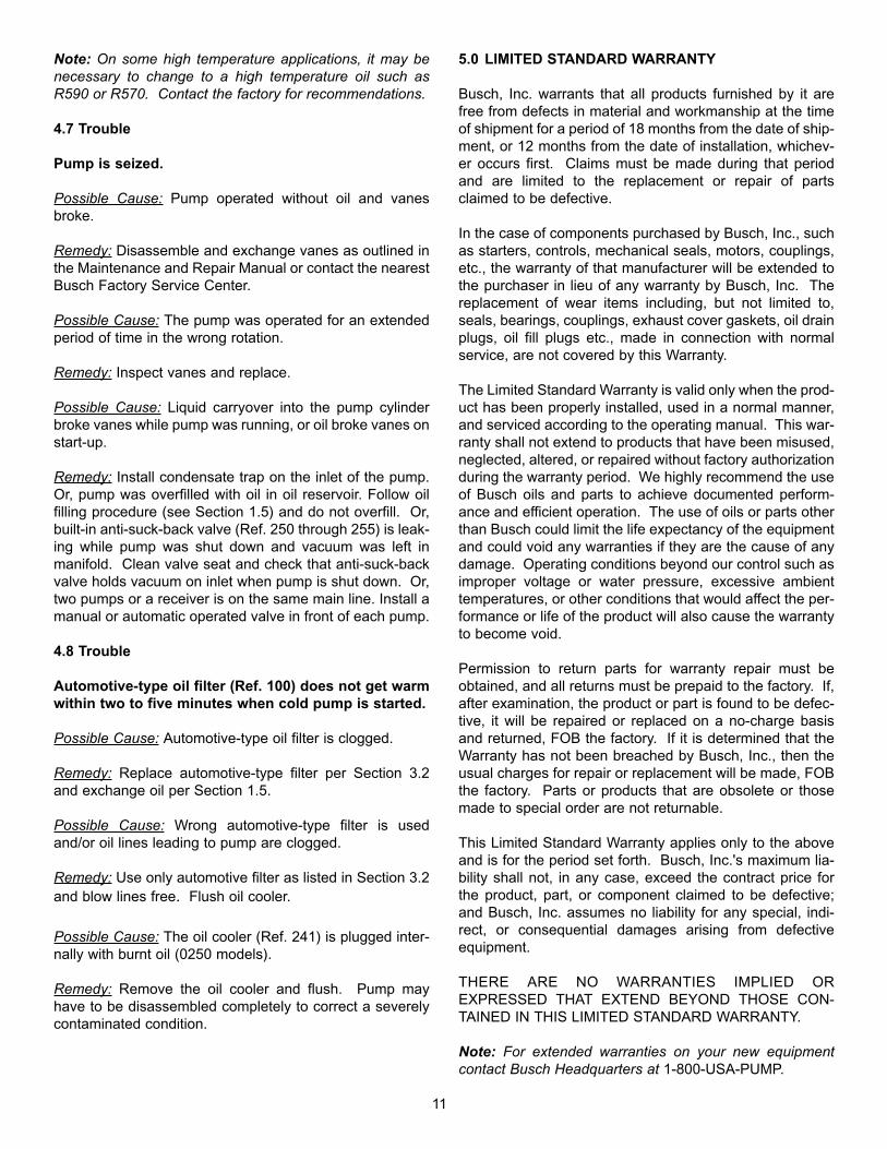
Note: On some high temperature applications, it may benecessary to change to a high temperature oil such asR590 or R570. Contact the factory for recommendations.
4.7 Trouble
Pump is seized.
Possible Cause: Pump operated without oil and vanesbroke.
Remedy: Disassemble and exchange vanes as outlined inthe Maintenance and Repair Manual or contact the nearestBusch Factory Service Center.
Possible Cause: The pump was operated for an extendedperiod of time in the wrong rotation.
Remedy: Inspect vanes and replace.
Possible Cause: Liquid carryover into the pump cylinderbroke vanes while pump was running, or oil broke vanes onstart-up.
Remedy: Install condensate trap on the inlet of the pump.Or, pump was overfilled with oil in oil reservoir. Follow oilfilling procedure (see Section 1.5) and do not overfill. Or,built-in anti-suck-back valve (Ref. 250 through 255) is leak-ing while pump was shut down and vacuum was left inmanifold. Clean valve seat and check that anti-suck-backvalve holds vacuum on inlet when pump is shut down. Or,two pumps or a receiver is on the same main line. Install amanual or automatic operated valve in front of each pump.
4.8 Trouble
Automotive-type oil filter (Ref. 100) does not get warmwithin two to five minutes when cold pump is started.
Possible Cause: Automotive-type oil filter is clogged.
Remedy: Replace automotive-type filter per Section 3.2and exchange oil per Section 1.5.
Possible Cause: Wrong automotive-type filter is usedand/or oil lines leading to pump are clogged.
Remedy: Use only automotive filter as listed in Section 3.2and blow lines free. Flush oil cooler.
Possible Cause: The oil cooler (Ref. 241) is plugged inter-nally with burnt oil (0250 models).
Remedy: Remove the oil cooler and flush. Pump mayhave to be disassembled completely to correct a severelycontaminated condition.
5.0 LIMITED STANDARD WARRANTY
Busch, Inc. warrants that all products furnished by it arefree from defects in material and workmanship at the timeof shipment for a period of 18 months from the date of ship-ment, or 12 months from the date of installation, whichev-er occurs first. Claims must be made during that periodand are limited to the replacement or repair of partsclaimed to be defective.
In the case of components purchased by Busch, Inc., suchas starters, controls, mechanical seals, motors, couplings,etc., the warranty of that manufacturer will be extended tothe purchaser in lieu of any warranty by Busch, Inc. Thereplacement of wear items including, but not limited to,seals, bearings, couplings, exhaust cover gaskets, oil drainplugs, oil fill plugs etc., made in connection with normalservice, are not covered by this Warranty.
The Limited Standard Warranty is valid only when the prod-uct has been properly installed, used in a normal manner,and serviced according to the operating manual. This war-ranty shall not extend to products that have been misused,neglected, altered, or repaired without factory authorizationduring the warranty period. We highly recommend the useof Busch oils and parts to achieve documented perform-ance and efficient operation. The use of oils or parts otherthan Busch could limit the life expectancy of the equipmentand could void any warranties if they are the cause of anydamage. Operating conditions beyond our control such asimproper voltage or water pressure, excessive ambienttemperatures, or other conditions that would affect the per-formance or life of the product will also cause the warrantyto become void.
Permission to return parts for warranty repair must beobtained, and all returns must be prepaid to the factory. If,after examination, the product or part is found to be defec-tive, it will be repaired or replaced on a no-charge basisand returned, FOB the factory. If it is determined that theWarranty has not been breached by Busch, Inc., then theusual charges for repair or replacement will be made, FOBthe factory. Parts or products that are obsolete or thosemade to special order are not returnable.
This Limited Standard Warranty applies only to the aboveand is for the period set forth. Busch, Inc.'s maximum lia-bility shall not, in any case, exceed the contract price forthe product, part, or component claimed to be defective;and Busch, Inc. assumes no liability for any special, indi-rect, or consequential damages arising from defectiveequipment.
THERE ARE NO WARRANTIES IMPLIED OREXPRESSED THAT EXTEND BEYOND THOSE CON-TAINED IN THIS LIMITED STANDARD WARRANTY.
Note: For extended warranties on your new equipmentcontact Busch Headquarters at 1-800-USA-PUMP.
11

TECHNICAL DATA “C” AND “E” SERIES
Type 0025 0040 0063 0100 0250
Theoretical Displacement CFM 20 28 41 63 180
Typical oil sump temperature* 188°F 195°F 190°F 204°F 204°F
Guaranteed Vacuum w/o gas ballastRA models Torr .5 .5 .5 .5 .5
RC models (standard) Torr 15 15 15 15 15
Maximum sound level dBA 70 70 70 71 81one meter from pump
Motor size - 3 phase HP 1 1/2 2 3 5 10
Motor size - 1 phase HP 1 1/2 2 3 5 NA
Pump motor speed (nominal) RPM 1750 1750 1750 1750 1750
Oil capacity Quart 1.4 1.4 2.5 2.7 7
Inlet connection NPT 1 1/4" 1 1/4" 1 1/4" 1 1/4" 2"
Pump weight lbs. 106 120 172 198 460
Shipping weight (approximate) lbs. 154 161 217 243 555
*Maximum oil temperature with 80°F ambient temperature and no supplemental oil cooling
MOTOR AND ELECTRICAL DATA “C / E” SERIES
Pump Type 0025 0040 0063 0100 0250
Motor US Mfg HP 1 1/2 2 3 5 1060Hz Motor Frame 145TC 145TC 182TC 184TC 215TC3 Phase RPM 1750 1750 1750 1750 1750
Volt 208-230/460 208-230/460 208-230/460 208-230/460 208-230/460
Full load 5.0-4.4 / 2.2 6.5/5.8/2.9 9.0-7.8/3.9 13.6-12.6/6.3 27-25/12.5Amperage
Motor US Mfg. HP 1 1/2 2 3 5 NA60 Hz Motor Frame 145TC 145TC1 Phase RPM 1750 1750
Volt 115/208/230 115/208/230Full LoadAmperage 16/8.4/8 24/13/12
12

Ref Description
1 Cylinder5 Socket set screw15 Rotor18 Bearing sleeve22 Vane25 Endplate, motor side26 Endplate, fan side30 Bearing31 Spacer, bearing to Seal35 Shaft seal42 Retainer ring43 Screw, hex head46 Gasket-ring47 Plug49 O-ring50 O-ring53 Screw, hex head54 Lockwasher57 Hex head screw58 Lockwasher60 Taper pin63 Plug64 Gasket-ring65 Shaft key66 Shaft key75 Exhaust box78 Baffle, expanded metal79 Demister pad80 Sheet metal baffle83 Oil sight glass84 Gasket ring, sight glass88 Oil fill plug89 Gasket ring, fill plug90 Exhaust pressure gauge95 Oil drain plug96 O-ring99 Pipe nipple100 Oil filter105 Cover, exhaust box106 Gasket, exhaust box cover107 Screw, exhaust box108 Lockwasher115 Exhaust filter bracket120 Exhaust filter121 O-ring125 Filter spring assembly126 Filter spring screw130 Strainer136 Gasket, exh. box service block137 Lockwasher138 Screw139 Service block140 Exhaust cover plate141 Exhaust cover gasket142 Socket head cap screw143 Lockwasher144 Retaining ring145 Housing, exhaust port146 Screw, exhaust housing148 Service block oil baffle149 Socket head cap screw150 Lockwasher
Ref Description
151 Exh. Screen, coarse152 Exh. Screen, fine159 Valve assembly, exhaust161 Oil service block162 Oil service block gasket163 Hex head cap screw164 Lockwasher165 Socket head cap screw166 Lockwasher168 O-ring169 Exhaust valve cover plate175 Socket head cap screw176 Lockwasher185 Gasket, cylinder/exhaust box186 Stud187 Lockwasher189 Stud190 Lockwasher191 Nut205 Exhaust cover side plate206 Cover plate gasket207 Socket head cap screw208 Lockwasher221 Hydraulic fitting banjo222 Hydraulic fitting, straight223 Hydraulic fitting, elbow/banjo224 Pipe adapter225 Hydraulic fitting230 Oil tubing231 Oil tubing232 Oil tubing238 Socket head cap screw239 Lockwasher241 Oil cooler242 O-ring244 Fan cover247 Socket head cap screw250 Housing, lower, inlet251 Valve plate, inlet252 Valve plate guide253 O-ring254 Spring, valve plate255 O-ring260 Inlet flange, upper261 Inlet screen265 Screw, hex head cap266 Lockwasher270 Plug271 Gasket ring275 Oil return valve276 Gasket ring284 Hydraulic, fitting banjo285 Screw, oil recirculation286 Banjo fitting housing288 Gasket ring289 Screw290 Oil return line, RA version291 Hyd. fitting, straight292 Carburetor jet293 Oil return line, RC version297 Screen fan guard300 Motor mounting bracket
Ref Description
301 Screw hex head cap302 Lockwasher306 Motor adapter flange307 Lockwasher311 Coupling half, pump side312 Coupling insert313 Coupling half, motor side315 Plastic clip320 Spacer321 Fan322 Axial fan323 Socket set screw326 Retainer ring331 Set screw333 Set screw340 Fan guard341 Screw, self tapping342 Sleeve, plastic345 Fan cover shield353 Socket head cap screw360 Lockwasher390 Eye bolt adapter391 Eye bolt392 Lockwasher393 Hex head screw400 Motor401 Screw, hex head cap402 Lockwasher409 Motor foot spacer411 Flat Washer413 Slotted set screw415 Screw, hex. head cap416 Stud, motor foot417 Set screw419 Spacer, motor foot421 Foot, rubber422 Foot, rubber423 Lockwasher424 Hex nut425 Stud430 Name plate431 Label "arrow"436 Maintenance label440 Gas Ballast Assembly470 Hyd. fitting banjo471 Tubing, gas ballast472 Valve, check gas ballast473 Coupling474 Filter, gas ballast475 Valve, pet cock476 Gas ballast elbow477 Pet cock valve478 Hex head cap screw479 Lockwasher
Note: This parts list includes parts for all thepumps covered by this manual. Your specificmodel might not necessarily have all thepart5 indicated in this list. Refer to the illus-tration for your specific model pump whencomparing part numbers or consult the facto-ry.
0025 - 0250 "C" & "E" Parts List
13

15

SECTION 6 - TROUBLESHOOTING GUIDE

TROUBLESHOOTING GUIDE
ALARM SCREEN MESSAGES CHECK WATER • Turn on water • Water pressure too low / twisted line • Check water inlet valve • Calcium deposit in dies or lines • Check water pressure sensor in pneumatic cabinet CHECK COMPRESSED AIR • Turn on compressed air • Air pressure too low / twisted line • Check setting on air pressure switch • Safety circuit open CHECK GAS • No gas available pressure below 2 bar / twisted line • Check gas sensor pressure switch • Check gas flush valve • Incorrect setting CHECK HEATERS • Turn on heaters • Check seal/form temperatures • Check electrical connection plug DIE NOT CLOSED • Check proximity switch on lift cylinder • Verify pneumatic signal to die lift cylinder • Check for lifting system jam • Check for foreign object caught in die • Check seal die for excessive filler plates DIE NOT OPEN • Check proximity switch on lift cylinder • Verify pneumatic signal to die lift cylinder • Check for lifting system jam

TROUBLESHOOTING GUIDE
ALARM SCREEN MESSAGES CHECK TRIM CANISTER • Check overload switch on the bottom of the trim canister • Check if trim canister is full • Make sure hoses are not blocked • Make sure trim canister is plugged in • Check electrical plug MAIN DRIVE OVERLOAD • Check drive motor • Check trim wound around sprockets • Check chain for jam or deformation • Check contactor and reset it ROTARY KNIFE BREAKER • Check knife for jam • Check blades for dull edges or nick's • Check rotary knife motor • Reset the breaker VACUUM PUMP OVERLOAD • Check oil vacuum pump • Check motor on vacuum pump E-STOP • Reset depressed e-stop • Check e-stop switch • Loose or broken wire on e-stop ERROR ON 4AD • Check for 24V DC to the module • Check led input / output ERROR ON 4ADTC • Check for 24V DC to the module • Check led input / output

TROUBLESHOOTING GUIDE
ERROR ON PLC PLC GREEN LIGHT IS FLASHING ON AND OFF • Check for short circuit in the 24V DC lead to the interface. • Check for possible removal of e-prom during machine cycle. • Check 3.6V lithium battery in PLC for low voltage. MTA-G1 INTERFACE GOES BLANK OR SHUTS OFF • Check for disconnection or short circuit in the 24V DC power to the interface.
ADVANCE DRIVE ADVANCE LENGTH VARIES • Make sure die centers are set correctly • Check encoder, lt. brown & dark brown encoder wires may have loose connection • Check advance length, adjust advance length in program • See cycle interruption • Check codes on parameter unit, see chart in manual for frequency drive errors • Check optocoupler signals for proper sequence FORMED POCKET CANNOT BE ALIGNED IN SEAL DIE • Check set point in program settings • Check die center dimension, information is engraved on the die tops • Check wiring between plc and little star for proper connections
CROSS CUT SYSTEM UNEVEN CUT • Check advance • Move cross cut knife • Adjust advance in program • Check blade holder • Check blade

TROUBLESHOOTING GUIDE
CYCLE INTERUPTION CHAIN ADVANCE INTERUPTED • Check e-stop • Check safeties. • If seal die is closed due to trapped vacuum, you must go to the manual valve
activation screen. Valve v3 must be turned "on”, then turn valve v12 "on" to vent the chamber. Finally turn valves v3 and v12 "off", turn valve v4 "on". Once the die is open; turn valve v4 “off” and return to the main screen.
• Turn the vacuum pump on. • Push advance arrow one time only to finish the cycle. • Put machine back in auto mode for continuous operation
DIE BOTTOMS
DIE NOT CLOSE • Check if die can not close because of mechanical interference • Check proximity switches on die lift cylinder • Change proximity switch DIE BOTTOM STICKS WHEN OPENED • Check vent time in program, ventilation time set too short • Check output signal to vent valve • Check pneumatic valve, ventilation valve faulty change it HOW TO OPEN • Activate V12 in maintenance valve program manually DIES ACTIVATING SLOWLY OR NOT AT ALL • Check the air supply to the machine for proper pressure and flow; 105psi at 30cfm (7
bar at 50 m3/hr). • Check the filter in the pneumatic cabinet for contamination which could cause an air
flow restriction. • Check the PLC inputs X6 and X11 for a red light as soon as the dies are closed. If
the red lights on the PLC are slow to light the proximity's are out of position. Check the proximity switches on the die lift cylinders for proper location and good mounting. The red LED's on the proximity's should light as soon as the cylinder has closed the dies. If they are too far towards the end of the cylinders this could cause a slow signal to the PLC for die closed in one or both lifting systems. Do the same for die open signals, X10 and X13.
• Has mid-stroke been turned on? This should always remain off. • Is there a mechanical obstruction causing the die to move slowly or get stuck?

TROUBLESHOOTING GUIDE
DIE BOTTOMS DIES ACTIVATING SLOWLY OR NOT AT ALL (cont’d) • Check the lifting system lubrication. • Check the die lift cylinder for damage or air pressure loss. • Check the air lines to the die lift cylinder for damage or pressure loss. • If the die lift cylinders are equipped with quick exhausts, check them for proper
function or contamination. • Check the blue 740 valves in the pneumatic cabinet, V1-V4, for contamination or
possible air pressure loss.
DIE TOPS WATER LEAKS IN DIE • Check o-ring between die and utility block • Check water hose • Check seal die top, calcium build up in the dies • Clean and remove calcium deposits
FORMING SYSTEM
WRINKLE IN POCKET/POCKETS NOT FORMED WELL • Check heating / forming time • Check heating / forming pressure • Check filler plates, use only aluminum plates • Check air line to die for damage • Check water, water temperature should be 50F-80F(10C-27C) • Check temperature of supply air, cold air used during air forming can cause poor
package form from premature cooling of the film DAMAGED POCKETS • Check radius plate for damage • Check film thickness and draw depth, use heavier material for deeper pockets FORMING DIE WHISTLES • Check 4 mm silicone cord for wear or damage • Check forming / heating pressure, decrease in pneumatic cabinet • Decrease forming time • Check die gap

TROUBLESHOOTING GUIDE
FILM INFEED FORMING
FILM ROLL FREE WHEELS • Check spanner nut on spindle tighten spanner nut on spindle • Check pneumatic brake operation • Check compressed air supply to brake • Check brake pad • Check tension roller springs FILM ROLL STICKS DURING ROTATION • Check brake pad for proper orientation, replace pad if worn excessively INFEED SPINDLE ALWAYS TIGHT (MAG. BRAKE ASSY.) • Check gap between magnetic brake, gap should be 0.000" to 0.003" ( 0.00mm to
0.076mm) • Check voltage at brake, should measure 0v dc to 6v dc as 5KΩ potentiometer is
rotated full left to full right (see magnetic brake calibration)
FILM INFEED NONFORMING
FILM ROLL STICKS DURING ROTATION (PNEUMATIC BRAKE SYSTEM) • Check brake pad for proper • Correct orientation, replace pad if worn excessively
FILM TRANSPORTATION SYSTEM
GRIPPERS DO NOT OPEN • Check chain tensioner • Remove half link
GAS FLUSH SYSTEM
NO GAS IN PACKAGE • Verify gas is "on " in the program • Check output Y11 • Check gas line / gas tank • Clean gas nozzle or pins • Check pin height, notch in the gas pin should be just above the top of the seal gasket
surface • Make sure the punch is cutting the flap so that it opens on the formed pocket side
rather than the gripper chain side of the film edge • If the gas pin punch in the form die is not making an appropriate cut for pin operation
adjust the punch height in the form die bottom

TROUBLESHOOTING GUIDE
GAS FLUSH SYSTEM NO GAS IN PACKAGE (cont’d) • Check wiring to PLC • Change or clean valve V14 on seal station side frame • Gas input pressure too high or too low • Increase gas flushing time • Change gas tank
LONGITUDINAL CUTTING UNEVEN CUT • Check condition of blades • Check alignment of blade in support rail
MAINTENANCE SCREEN MESSAGES
Check pump oil • Check vacuum pump oil and reset counter afterwards Change pump oil • Change vacuum pump oil and reset counter afterwards Oil chains • Inspect chains and oil chains if necessary Grease bearings • Grease bearings and reset counter afterwards Check lubricator • Fill up mini-lubricator unit with oil Grease cross cut • Grease cross cut pneumatic cylinder
POOR SEAL QUALITY
• Check seal area for product contamination. • Check for proper film path on top and bottom web. • Check seal gasket. • Check seal temperature setting. • Check seal pressure regulator. • Check seal time setting in program. • Check seal valve activation. • Check air line to seal die top cylinders for damage or possible disconnection. • Check seal plate for proper travel. • Check the seal cylinders for damaged return springs or cylinder rod damage • Check seal cylinder rod t-seals for damage

TROUBLESHOOTING GUIDE
SEALING DIE TOP/FORM DIE TOP
TEMPERATURE DROPS OR ELEVATES • Check the temperature settings in the program settings screen for recent changes. • Check the heat multiplier settings for recent changes. • Check the circuit breakers in the electrical cabinet. They are labeled CB5 and CB6
on the electric panel layout. Reset the circuit breaker if necessary. If it trips a second time check for a short circuit or low power supply to the machine.
• Check the die plug connection. If there is evidence of charring or discoloration clean the contacts. Also check the pins and sockets for proper seating in the plug (i.e. not pushed out of place or damaged from multiple connections). A bad connection on the thermocouple contacts will cause the temperature reading to go up into the 3000C + range.
• Check the wire leads from the heat plates to the wire port for damage or short circuit. • Check the terminal strip screws in the wire port of the die top. • Check the SSR’s for a proper operation. With the main power off check between
poles 1 and 2 of the SSR for continuity. If continuity exists the SSR is bad. A replacement is required.
• Check the thermocouple output at the terminal strip in the wire port. The reading will be approximately 0.4mV at 700F from a good thermocouple.
• Check the resistance across the heaters at the terminal strip in the wire port. The resistance measured will be approximately as listed:
220 Volt Number of heaters Resistance
2 24.5Ω 3 16.3Ω 4 12.3Ω
380 Volt Number of heaters Resistance 2 73.5Ω 3 49.0Ω 4 36.8Ω
VACUUM SYSTEM
LOW VACUUM IN PACKAGE / RESIDUAL O2 LEVEL TOO HIGH • Check the vacuum time set in the current program being run on the machine. • Verify proper width of top web. • Check vacuum pump oil level. • Check for physical damage to the seal die bottom or top. • Check the seal gasket for damage. • Check for contamination between the die bottom platform and the seal die bottom. • Check filler plate height in seal die bottom for proper product support.
• The distance from the top of the plastic filler plates to the top of the seal gasket should be the same as the product height • This depth may be adjusted deeper than the product height up to 6mm, but
should never be less than the overall product height.

TROUBLESHOOTING GUIDE
LOW VACUUM IN PACKAGE / RESIDUAL O2 LEVEL TOO HIGH (cont’d) • Check the seal die top heat plate for an even activation. This may be done in the
manual valve operation screen. All alarms must be eliminated on the alarm screen prior to this test to enable proper manual valve operation. Remove the film under the seal die top to allow easier access for inspection. An inspection mirror and flashlight will be needed to inspect the seal heat plate while the die top is installed on the machine. In the manual valve operation screen turn V9 (seal valve) on by highlighting the on/off value and pressing “enter” to activate the seal heat plate. The heat plate should come down evenly and without interference. If the heat plate does not come down evenly this may be a result of interference or a malfunctioning seal cylinder. Inspect the edges of the heat plate for rub marks or scratches in the Teflon coating. If interference during travel is evident the die top must be removed and the heat plate must be adjusted on its mounting. If there is no interference in the travel the die top must be removed and disassembled to inspect the seal cylinders for failure or internal damage. After all necessary adjustments and inspections are completed return the seal valve V9 to its “off” setting.
• Verify that the signals to the die bottom and die top vacuum valves are operating according to the time settings in the current program being ran on the machine.
• Check the pneumatic lines from the valves that pilot the vacuum valves for damage or air leaks.
• Check the pneumatic valve solenoids on V7 and V8 (seal die bottom and seal die top vacuum valves) for activation. Replace solenoids if a signal is received at the solenoid, but the valve does not activate.
• Check the vacuum valves and the vent valves for internal contamination or damaged o-rings by removing the side covers on the valves. Be careful not to lose or damage any internal parts.
VACUUM SYSTEM INTEGRITY TESTING MANUALLY
CHECK VACUUM PUMP PLUMBING SYSTEM 1. Visually inspect the vacuum hoses for damage and tighten all hose clamps in the
vacuum system. 2. Connect a vacuum gauge to t-fitting for vacuum pump. 3. Run pump for 30 seconds for maximum vacuum level. 4. Stop vacuum pump. 5. Check vacuum level deviation for 1 minute. 6. Make a note of the maximum level reached and the remaining vacuum level after 1
minute. 7. A deviation of 10 torr / 13 mB in one minute is acceptable.

TROUBLESHOOTING GUIDE CHECK SEAL DIE TOP VACUUM 1. Advance forming film to separate the seal die into two separate chambers, top and
bottom, with a flat web. • Make sure there is no damage to the film (i.e. Holes, tears, or the film out of the
grippers). 2. Connect a vacuum gauge to the t-fitting for the seal die top. 3. All alarms must be eliminated on the alarm screen prior to this test to enable proper
manual valve operation. 4. In the manual valve operation screen turn V3 (seal die close) on by highlighting the
on/off value and pressing “enter” to close the seal die. 5. In the manual valve operation screen turn V7 and V8 (die top and die bottom vacuum
valves) on by highlighting the on/off value and push “enter” to turn these valves “on”. Both valves must be activated to keep the film barrier stabilized.
6. Run pump for 30 seconds for maximum vacuum level. 7. Check vacuum level deviation for 1 minute. 8. Make a note of the maximum level reached and the remaining vacuum level after 1
minute. 9. A deviation of 10 torr / 13 mB in one minute is acceptable. 10. Turn V7 and V8 off by highlighting the on/off value and push “enter” to turn these
valves “off”. 11. Turn V12(seal die vent) on by highlighting the on/off value and push “enter” to turn
this valve “on” after hearing the die vent return the value to “off”. 12. In the manual valve operation screen turn V3 (seal die close) off by highlighting the
on/off value and pressing “enter” to open the seal die. CHECK SEAL DIE BOTTOM VACUUM • Repeat the steps listed above for the seal die top vacuum with the exception of
number 2. The gauge must be connected to the die bottom t-fitting. POSSIBLE CAUSES FOR VACUUM LEAKS • Inspect the condition of the epoxy on the vacuum system plumbing.
• If new epoxy is required VC999 Packaging Systems recommends “3M DP-100 epoxy”.
• Clean all surfaces with a wire brush and acetone prior to applying new epoxy. • Check for physical damage on the die top and die bottom. • Check the seal gasket for damage.
• Replace it if it is damaged. • Check the rod t-seals around the seal cylinder shafts.
• Check these by pressing your finger over the vent port of the seal cylinders during the vacuum cycle of the machine.
• Replacements are needed if a strong vacuum is felt against your finger. • Proper lubrication of these seals with o-ring lubricant or petroleum jelly is
necessary during installation.
TROUBLESHOOTING GUIDE
VACUUM SYSTEM INTEGRITY TESTING MANUALLY POSSIBLE CAUSES FOR VACUUM LEAKS (cont’d) • Check the o-rings between the die top and the utility block.
• Also check the o-ring between the die bottom and the platform. • Lubricate the o-rings with o-ring lubricant or petroleum jelly. • Replace them if they are damaged or missing.
• Check the potting compound in the die top wire port. • This compound is a black rubber-like epoxy that is used to seal the back of the
plug from moisture and vacuum leaks. • If the compound appears cracked isn’t sealed well around the wires it needs to
be removed and replaced. • VC999 Packaging Systems recommends “3M DP-270 potting compound”.
Make sure all old compound is removed from the wire port, plug and wires and these surfaces are cleaned with acetone when replacing potting compound. This will ensure good adhesion on these surfaces.
• Check the vacuum valves and the vent valves for internal contamination or damaged o-rings by removing the side covers on the valves, being careful not to lose or damage any internal parts.
• Visually inspect the vacuum hoses for damage and tighten all hose clamps in the vacuum system.
• Check 4mm silicon cord between the seal die bottom and the seal frame for damage or wear.
• Check the gas flush nozzle gasket for proper installation, damage or excessive wear.
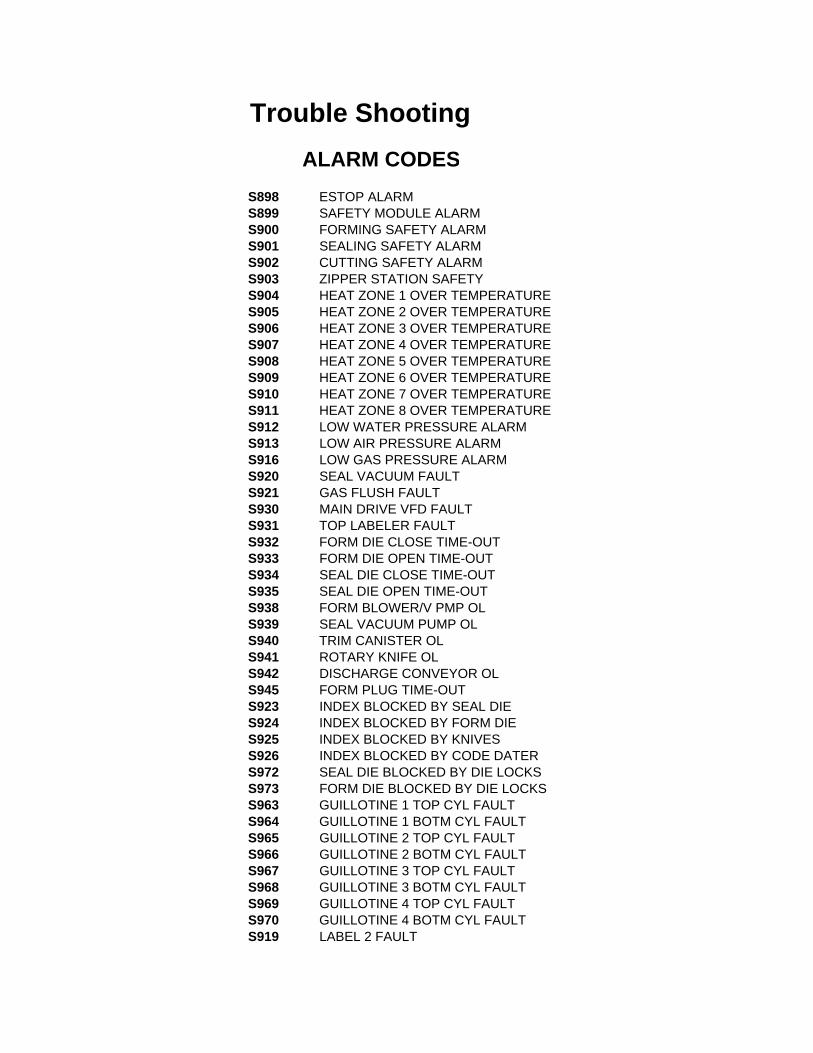
Trouble Shooting ALARM CODESS898 ESTOP ALARMS899 SAFETY MODULE ALARMS900 FORMING SAFETY ALARMS901 SEALING SAFETY ALARMS902 CUTTING SAFETY ALARMS903 ZIPPER STATION SAFETYS904 HEAT ZONE 1 OVER TEMPERATURES905 HEAT ZONE 2 OVER TEMPERATURES906 HEAT ZONE 3 OVER TEMPERATURES907 HEAT ZONE 4 OVER TEMPERATURES908 HEAT ZONE 5 OVER TEMPERATURES909 HEAT ZONE 6 OVER TEMPERATURES910 HEAT ZONE 7 OVER TEMPERATURES911 HEAT ZONE 8 OVER TEMPERATURES912 LOW WATER PRESSURE ALARMS913 LOW AIR PRESSURE ALARMS916 LOW GAS PRESSURE ALARMS920 SEAL VACUUM FAULTS921 GAS FLUSH FAULTS930 MAIN DRIVE VFD FAULTS931 TOP LABELER FAULTS932 FORM DIE CLOSE TIME-OUTS933 FORM DIE OPEN TIME-OUTS934 SEAL DIE CLOSE TIME-OUTS935 SEAL DIE OPEN TIME-OUTS938 FORM BLOWER/V PMP OLS939 SEAL VACUUM PUMP OLS940 TRIM CANISTER OLS941 ROTARY KNIFE OLS942 DISCHARGE CONVEYOR OLS945 FORM PLUG TIME-OUTS923 INDEX BLOCKED BY SEAL DIES924 INDEX BLOCKED BY FORM DIES925 INDEX BLOCKED BY KNIVESS926 INDEX BLOCKED BY CODE DATERS972 SEAL DIE BLOCKED BY DIE LOCKSS973 FORM DIE BLOCKED BY DIE LOCKSS963 GUILLOTINE 1 TOP CYL FAULTS964 GUILLOTINE 1 BOTM CYL FAULTS965 GUILLOTINE 2 TOP CYL FAULTS966 GUILLOTINE 2 BOTM CYL FAULTS967 GUILLOTINE 3 TOP CYL FAULTS968 GUILLOTINE 3 BOTM CYL FAULTS969 GUILLOTINE 4 TOP CYL FAULTS970 GUILLOTINE 4 BOTM CYL FAULTS919 LABEL 2 FAULT

S948 SEAL DIE LOCK FAULTS949 FORM DIE LOCK FAULTS961 GUILLOTINE POSITION CYLINDER 1S962 GUILLOTINE POSITION CYLINDER 2S824 NETWORK ALARM - PRINTERS825 NETWORK ALARM - ZIPPERS826 PRINTER X AXIS FAULTS827 PRINTER Y AXIS FAULTS828 PRINTER LIMIT SWITCH FAULTS829 INDEX BLOCK BY PRINTERS830 PRINTER MEMORY ERRORS834 ZIPPER MEMORY ERRORS835 INDEX BLOCKED BY ZIPPERS836 ZIPPER DIE LOCK FAULTS837 ZIPPER DIE NOT CLOSED FAULTS838 ZIPPER DIE NOT OPEN FAULTS844 ZIPPER ZONE 1 OVER TEMPS845 ZIPPER ZONE 2 OVER TEMPS846 ZIPPER ZONE 3 OVER TEMPS847 ZIPPER ZONE 4 OVER TEMPS848 ZIPPER ZONE 5 OVER TEMPS849 ZIPPER ZONE 6 OVER TEMPS850 ZIPPER ZONE 7 OVER TEMPS851 ZIPPER ZONE 8 OVER TEMPS974 GUILLOTINE 5 TOP CYLINDER FAULTS975 GUILLOTINE 5 BOTTOM CYLINDER FAULTS943 FILLER TIMEOUT FAULTS953 CONFIRMATION STATION 1 NOT CLOSEDS954 CONFIRMATION STATION 1 NOT OPENS951 CONFIRMATION STATION 2 NOT CLOSEDS952 CONFIRMATION STATION 2 NOT OPENS960 GUILLOTINE POSITION CYLINDER 3S976 SLICER FAULTS927 SHAPE CUTTER OLS875 CC LINK MASTER ALARMS876 CC LINK MASTER LINK ALARMS877 CC LINK STATION 1 ALARMS878 CC LINK STATION 2 ALARMS879 CC LINK STATION 3 ALARMS700 FILLER NOT READY FAULTS701 STATION 1 FILLERS FAULTS702 STATION 2 FILLERS FAULTS703 STATION 3 FILLERS FAULTS704 STATION 4 FILLER FAULTS705 STATION 5 FILLER FAULTS706 STATION 6 FILLER FAULTS707 STATION 7 FILLER FAULTS708 STATION 8 FILLER FAULTS709 STATION 9 FILLER FAULTS710 STATION 10 FILLER FAULTS711 STATION 11 FILLER FAULTS720 FILLER TIMEOUT FAULT

S721 NETWORK FILLER 1 TIMEOUT FAULTS722 NETWORK FILLER 2 TIMEOUT FAULTS723 NETWORK FILLER 3 TIMEOUT FAULTS724 NETWORK FILLER 4 TIMEOUT FAULTS725 NETWORK FILLER 5 TIMEOUT FAULTS726 NETWORK FILLER 6 TIMEOUT FAULTS727 NETWORK FILLER 7 TIMEOUT FAULTS728 NETWORK FILLER 8 TIMEOUT FAULTS729 NETWORK FILLER 9 TIMEOUT FAULTS730 NETWORK FILLER 10 TIMEOUT FAULTS731 NETWORK FILLER 11 TIMEOUT FAULTS732 NETWORK FILLER 12 TIMEOUT FAULTS733 NETWORK FILLER 13 TIMEOUT FAULTS734 NETWORK FILLER 14 TIMEOUT FAULTS735 NETWORK FILLER 15 TIMEOUT FAULTS736 NETWORK FILLER 16 TIMEOUT FAULTS737 NETWORK FILLER 17 TIMEOUT FAULTS738 NETWORK FILLER 18 TIMEOUT FAULTS739 NETWORK FILLER 19 TIMEOUT FAULTS740 NETWORK FILLER 20 TIMEOUT FAULTS741 NETWORK FILLER 21 TIMEOUT FAULTS742 NETWORK FILLER 22 TIMEOUT FAULTS977 HEAT ZONE 1 AUTO TUNE ERRORS978 HEAT ZONE 2 AUTO TUNE ERRORS979 HEAT ZONE 3 AUTO TUNE ERRORS980 HEAT ZONE 4 AUTO TUNE ERRORS981 HEAT ZONE 5 AUTO TUNE ERRORS982 HEAT ZONE 6 AUTO TUNE ERRORS983 HEAT ZONE 7 AUTO TUNE ERRORS984 HEAT ZONE 8 AUTO TUNE ERRORS854 ZIPPER ZONE 1 AUTO TUNE ERRORS855 ZIPPER ZONE 2 AUTO TUNE ERRORS856 ZIPPER ZONE 3 AUTO TUNE ERRORS857 ZIPPER ZONE 4 AUTO TUNE ERRORS858 ZIPPER ZONE 5 AUTO TUNE ERRORS859 ZIPPER ZONE 6 AUTO TUNE ERRORS860 ZIPPER ZONE 7 AUTO TUNE ERRORS861 ZIPPER ZONE 8 AUTO TUNE ERRORS995 PLC MEMORY ERRORS992 SERVO PUNCH FAULTS993 SERVO PUNCH END OF STROKE FAULTS994 SERVO PUNCH NOT READYS991 SERVO PUNCH HOME ERROR

Water flow diagram/Wasser
Ablaufdiagramm
Water checkvalve/ Wasser
Rückschlagventil
Inflow/Zufluß
Machine flush checkvalve/ MaschineWasserschwall
Rückschlagventil
Water pressure sensor/ WasserDruck Sensor
Forming Die Bottom/Formen
Druckgußform Boden
Form Die Top/Formen
DruckgußformOberteil
Sealing Die Top/VersiegelungDruckgußform
Oberteil
Floor drain/BodenAblauf
Water Chiller/Wasser Kühler
Outflow/Abfluß
Opt
iona
l Wat
er R
etur
n/W
ahlw
eise
Was
ser
Ein
kom
men
Purgeswitch/
ReinigenSchalter
Com
pressed air/D
ruckluft
DEAR CUSTOMER, We will greatly appreciate your comments to make this troubleshooting guide a valuable instrument to minimize frustration and downtime. PLEASE SEND YOUR RECOMMENDATIONS TO: FAX : 816-472-1999 TEL : 816-472-8999 E-MAIL : [email protected]

SECTION 7 - PNEUMATIC DIAGRAMS

419 East 11th Avenue, Kansas City, MO 64116Telephone 816-472-8999 Fax 816-472-1999
Scale: Drawn By:
Checked by:
Drawing File:
Sheet of 2
NTSMAH
VC999 Pneu. Circuit
V216To Form StationManifold
GasSupplyGas Flush To Squeeze Knives
TopSealDie
NFUnwind Tension Cylinder
Code Dater Cylinders
Cross Cut Cylinders
Optional Guillotine Cylinders
Vacuum Valves
Die Lock Cylinders
Seal Die Lift Cylinders
P
V4
V216
V211
V213
V215
V280
V230
V231
V208
V207
V3V1 V2
V10
V9
V
X
Form Die Lift Cylinders
2
Standard Machine Pneumatics

419 East 11th Avenue, Kansas City, MO 64116Telephone 816-472-8999 Fax 816-472-1999
Scale: Drawn By:
Checked by:
Drawing File:
Sheet of 2
NTSMAH
VC999 Pneu. Circuit
Vacuum Valve
Spa
re
From Air Prep Supply
X
Air Blow Off for FilmDie Lock Cylinders
V105
V186
V180
V106
V112
V145
V187
Standard Form Station
1

419 East 11th Avenue, Kansas City, MO 64116Telephone 816-472-8999 Fax 816-472-1999
Scale: Drawn By:
Checked by:
Drawing File:
Sheet of 2
NTSMAH
VC999 Pneu. Circuit
Spa
re
From Air Prep Supply
Vacuum Valve
Die Lock Cylinders
Vacuum Valve
V188
V
X
Form Pre Heat Plate
V105
V186
V180
V106
V112
V145
Pre Heat Form Station
1

4
6
9
10
4
8
72
1
3
10
11
1716
22
Sheet1Packaging Systems
R
Telephone 816-472-8999 Fax 816-472-1999419 East 11th Avenue Kansas City, MO 64116
Drawn by
Date
Checked by
Scale M. Vogler
Part No.
1:6PRS 457282
assm, pneu frm st
Drawing File 457282 of 4
ITEM NO. QTY. Dept./Part No. DESCRIPTION1 1 PRS 456237 valv, NO SMC 4std2 2 PRS 456239 muflr, 10mm SMC3 1 PRS 458315 assm, air reg ST4 9 PRS450908 fit, 8x1/4npt 905 8 FSC 452807 plug, 1/4 NPT SS6 1 PRS 450992 fit, 1/2x1/2npt 907 1 PRS 454978 assm, sensor water pressure8 1 ELR 451027 strn rlf, PG16x14mm9 1 ELR 455215 strn rlf, 3/4"x alu
10 3 PRS 451091 fit, 8 Y union11 1 ELR 457123 strn rlf, M32x10mm12 2 PRS450907 fit, 8x1/4npt ST13 1 PRS 455938 fit, 1/2x1/2npt brhT14 2 PRS456021 fit, 6x1/4npt ST15 2 PRS 457210 fit, 4x1/4npt ST16 2 FSC 450983 screw, M5x10 SHCS17 2 FSC451033 washer, M5 fl reg18 1 FSC 455359 plug, 1/2 npt flush19 2 PRS451161 fit, 6x1/4npt 9020 1 ELR 454302 plug, M25x1.521 4 ELR 451247 plug, thread PG-1622 2 PRS 454266 fit, 8x8 FC ST
12
14
15
18
13
20
21
5
19

Packaging Systems
R
Telephone 816-472-8999 Fax 816-472-1999419 East 11th Avenue Kansas City, MO 64116
Drawn by
Date
Checked by
Scale M. Vogler
Part No.
1:4PRS 457282
assm, pneu frm st
Drawing File 457282 ofSheet2 4
Notes:
1) Connect corresponding letters (A,B,C,D,E,F,G,H,M,N) with PRS451581 (8 mm neon green tubing).
2) Connect corresponding letters (K,L,P) with PRS450904 (8 mm blue tubing).
3) Connect corresponding letter J with PRS450993 (1/2" clear tubing).
4) Connect letter P to water purge assembly in form cabinet.
5) Connect letter M to bottom side of water purge assembly.
6) Tubing between the corresponding letters are associated with:
(D,F) DIE LIFT LOCK CYL (UTILITY)(P) WATER PURGE AIR(J) MAIN AIR IN(G,H) DIE LIFT LOCK CYL (OPERATOR)(N) COOLING WATER OUT(K) COOLING WATER IN(Z) PILOT AIR
A
B
M K
N N
Z
G
H
JE
D
F
CF
D
PK
J
A
B
E
C
G
H

Packaging Systems
R
Telephone 816-472-8999 Fax 816-472-1999419 East 11th Avenue Kansas City, MO 64116
Drawn by
Date
Checked by
Scale M. Vogler
Part No.
1:4PRS 457282
assm, pneu frm st
Drawing File 457282 ofSheet3 4
Notes:
1) Valve labeling:
V105 - (Vac valve die top) V106 - (Vac valve die bottom) V112 - (Vent valve die bottom) V145 - (Vent valve die top) V180B/A - (Die locks) V186 - (Pos air form)
V112V145
V186V180-A
V106V105
V180-B

K
F
D
Main air in
Die Lift Valve
P
G
H
Z
N
Packaging Systems
R
Telephone 816-472-8999 Fax 816-472-1999419 East 11th Avenue Kansas City, MO 64116
Drawn by
Date
Checked by
Scale M. Vogler
Part No.
1:4PRS 457282
assm, pneu frm st
Drawing File 457282 ofSheet4 4
Notes:
1) Connect corresponding letters (K, N) with PRS450904 (8 mm blue tubing).
2) Connect corresponding letter (J, R) with PRS450993 (1/2" clear tubing).
3) Connect corresponding letters (D, F, G, H) with PRS451071 (6mm clear tubing).
4) Connect letter (P, Z) with PRS453552 (4mm clear tubing).
5) Tubing between the corresponding letters are associated with:
(G, H) DIE LIFT LOCK (OPERATOR)(P) PURGE AIR(J) MAIN AIR FROM CABINET(D, F) DIE LIFT LOCK (UTILITY)(N) COOLING WATER OUT TO DIE BOTTOM(K) COOLING WATER IN(Z) PILOT AIR

ITEM NO. QTY. Dept./Part No. DESCRIPTION
1 2 PRS450907 fit, 8x1/4npt ST
2 1 PRS 457972 mnt, regulator SMC
3 1 PRS 457971 reg, air 1/4" w/gagS
3
2
1
Sheet1Packaging Systems
R
Telephone 816-472-8999 Fax 816-472-1999419 East 11th Avenue Kansas City, MO 64116
Drawn by
Date
Checked by
Scale M. Vogler
Part No.
1:1PRS 458315
assm, air reg ST
Drawing File 458315 of 1

Packaging SystemsTelephone 816-472-8999 Fax 816-472-1999419 East 11th Avenue Kansas City, MO 64116
Drawn by
Date
Revisions:
Checked by
Scale J. Romfo
Part No.
1:1PRS 454978
assm, sensor water pressure
Drawing File 454978 ofSheet1 1
3
21
4
5
6
ITEM NO. QTY. DEPARTMENT PART NO. DESCRIPTION LOCATION MATERIAL MATERIAL P/N
1 1 ELR 451183 sensor, water pressure RR2 D13 N/A N/A
2 1 PRS 451620 fit, 1/8nptf T union RR2 B13 N/A N/A3 1 PRS 451053 fit, 8x1/8npt 90 X06H50 N/A N/A
4 1 PRS 451336 fit, 1/8npt close np RR2 A03 N/A N/A5 1 PRS 451108 valve, check 1/8" nptf RR2 D15 N/A N/A6 1 PRS 451492 fit, 1/8nptx1/4npt X06G43 N/A N/A

2 1
1
3
7
654
ITEM NO. QTY. Dept./Part No. DESCRIPTION
1 4 PRS450908 fit, 8x1/4npt 90
2 2 FSC 452807 plug, 1/4 NPT SS
3 3 PRS 457201 plug, 8 tube push in
4 1 PRS 458252 assm, form heat valve
5 2 FSC 450983 screw, M5x10 SHCS6 2 FSC451033 washer, M5 fl reg
7 1 PRS 460715 assm, filtr micromist
Sheet1Packaging Systems
R
Telephone 816-472-8999 Fax 816-472-1999419 East 11th Avenue Kansas City, MO 64116
Drawn by
Date
Checked by
Scale M. McMullin
Part No.
1:8PRS 458690
assm, vlv standard
Drawing File 458690 of 3

A
AJK
B
Inside Form Station Cabinet
C
B
J
K
Inside Form Station Cabinet
N
Inside Form Station Cabinet
C
Packaging Systems
R
Telephone 816-472-8999 Fax 816-472-1999419 East 11th Avenue Kansas City, MO 64116
Drawn by
Date
Checked by
Scale M. McMullin
Part No.
1:20PRS 458690
assm, vlv standard
Drawing File 458690 ofSheet2 3
Notes:
1) Connect corresponding letters (A,B,C,J,K) with PRS451581 (8mm neon green tubing).

K
J
J
K
G
Back side of Form Station Cabinet
N
Back side of Form Station Cabinet(Operator Side)
Z
C
Z
G
H (To Form die top)
C
Back side of Form Station Cabinet
(Utility side)
Notes;
1) Connect corresponding letters (C,J,K) with PRS451581 (8mm neon green tubing).
2) Connect corresponding letter (Z) with PRS450902 (4mm clear tubing).
3) Connect corresponding letter (G,H) with PRS450993 (1/2" clear tubing).
Packaging Systems
R
Telephone 816-472-8999 Fax 816-472-1999419 East 11th Avenue Kansas City, MO 64116
Drawn by
Date
Checked by
Scale M. Vogler
Part No.
1:20PRS 458690
assm, vlv standard
Drawing File 458690 ofSheet3 3

Packaging Systems
R
Telephone 816-472-8999 Fax 816-472-1999419 East 11th Avenue Kansas City, MO 64116
Drawn by
Date
Checked by
Scale M. Vogler
Part No.
1:1.5PRS 458252
assm, form heat valve
Drawing File 458252 ofSheet1 1
3
4
2
6
15
3
11
9
10
7
8
ITEM NO. QTY. DEPARTMENT PART NO. DESCRIPTION1 1 PRS 454445 valv, soln 3/2 24dc2 1 PRS 451516 fit, 6xM5 ST3 2 PRS 454706 fit, 1/2x3/8npt ST4 1 ELR 454446 cabl, sol valv CPE245 2 FSC 451147 screw, M6x50 SHCS6 2 RSA R62459 spcr, 8mmidx6mmlg7 1 PRS 457969 fit, 1/4nptfx1/4nptm8 1 PRS 455385 fit, 3/8nptmx1/4nptm9 1 PRS R60132 q-exhaust, 1/4npt
10 1 PRS 452154 muflr, 1/4npt shell11 1 PRS 450907 fit, 8x1/4npt ST

2
3
4
1
2
5
REVISIONSREV. DESCRIPTION DATE APPROVED
ITEM NO. QTY. DEPT. PART NO. DESCRIPTION
1 1 PRS 456238 valv, NO SMC 5std
2 2 PRS 456233 assm, valv soln 4/2 24dc3 1 PRS 456644 air prep, SMC assm
4 2 PRS 456239 muflr, 10mm SMC
5 2 PRS 456234 assm, valv soln dbl NO
456273 ofSheet1Packaging Systems
R
Telephone 816-472-8999 Fax 816-472-1999419 East 11th Avenue Kansas City, MO 64116
Drawn by
Date
Checked by
Scale M. Vogler
Part No.
1:5PRS 456273
assm, pneu seal st
Drawing File 4

Notes:
1) Mufflers not shown for clarity.
2) Connect corresponding letters (E,F,G,H,K,L) with PRS451581 (8mm neon green tubing.)
3) Connect corresponding letters (A,B,C,D,E) with PRS450993 (1/2" clear tubing).
4) Connect corresponding letter(s) (J) with PRS453552 (6mm clear tubing).
5) Label the tubing between the corresponding letters with:
(B) - MAIN AIR FORM CABINET(E) - MAIN AIR V209(F) - DANCER ARM CYL(G) - CODE DATER(H) - CROSS CUT(J) - DIE LIFT LOCK(K) - PRESS SENSOR & SQUEEZE KNIFE(L) - VACUUM VALVES
Packaging Systems
R
Telephone 816-472-8999 Fax 816-472-1999419 East 11th Avenue Kansas City, MO 64116
Drawn by
Date
Checked by
Scale M. Vogler
Part No.
1:4PRS 456273
assm, pneu seal st
Drawing File 456273 ofSheet2 4
L
A (1 : 1)
D
FG
H
J
K
A
BC D
E
DF GG HHHH
J LL K
A

Packaging Systems
R
Telephone 816-472-8999 Fax 816-472-1999419 East 11th Avenue Kansas City, MO 64116
Drawn by
Date
Checked by
Scale M. Vogler
Part No.
1:4PRS 456273
assm, pneu seal st
Drawing File 456273 ofSheet3 4
Notes;
1) Label as shown.
MAIN AIR SHUT OFF
MAIN AIR REG MAIN AIR DUMPVALVE MANIFOLD REG SEAL PRESS REG
V231 V
208V
230 V207
V280
V213
V215
V211
V216

Packaging Systems
R
Telephone 816-472-8999 Fax 816-472-1999
Drawn by
419 East 11th Avenue Kansas City, MO 64116
Revisions:
Date
Scale
456238
R. Swaney
Part No.
1:1.5456238PRS
Drawing File
valv, add-on layout
ofSheet1
Checked by
1
VACUUM VALVE BALANCE (PRS456234)VACUUM VALVE PACKAGE (PRS456234)
V230 V
207
V2 31 V
208V
2 80B V280 A
V2 13B V
213 A
V2 15B V
215 A
V2 11B V
211 A
CUTTING (cross cut) (PRS456233)DIE LIFT LOCKS (PRS456233)
DANCER ARM (PRS456233)
ADD-ON CUTTING (cross cut / guillotine top) (PRS456233)
ADD-ON CUTTING (cross cut / guillotine top) (PRS456233)
ADD-ON CUTTING (cross cut / guillotine bottom) (PRS456233)
ADD-ON CUTTING (cross cut / guillotine bottom) (PRS456233)
CUTTING (cross cut) (PRS456233)
V216A
FILM BRAKE (PRS456233)
V218B V
218 A
V2 19B V
219 A
V2 28B V
228 A
V2 29B V
229 A
V2 48B V
248 A
V2 49B V
249 A
V2 51A
V2 20B V
220 A
V2 35A
ADD-ON CUTTING (cross cut / guillotine top) (PRS456233)
V252B V
252 A
ADD-ON CUTTING (cross cut / guillotine bottom) (PRS456233)
V234B V
234 A
LOADING GRID (PRS456233)
HOLE PUNCH (PRS456233)ADD-ON CUTTING (PRS456233)
TRANSVERSING PUNCH CYLINDER (PRS456233)
ADD-ON
CODE DATER (PRS456233)
STANDARD
STANDARD

V208 V207
V230V231
Non-Pin GasManifold
Pin GasManifold
Packaging Systems
R
Telephone 816-472-8999 Fax 816-472-1999419 East 11th Avenue Kansas City, MO 64116
Drawn by
Date
Checked by
Scale M. Vogler
Part No.
1:3PRS 456273
assm, pneu seal st
Drawing File 456273 ofSheet4 4
V207
V230V231
V208

1
2
3
4
ITEM NO. QTY. DEPARTMENT PART NO. DESCRIPTION
1 1 PRS 455970 valv, soln 4/2 24dc
2 1 PRS 455965 manfld, seg blk SMC
3 2 PRS 455966 fit, 8 cartrdg SMC
4 2 PRS 455967 tie-rod, manifld SMC
REVISIONSREV. DESCRIPTION DATE APPROVED
Packaging Systems
R
Telephone 816-472-8999 Fax 816-472-1999419 East 11th Avenue Kansas City, MO 64116
Drawn by
Date
Checked by
Scale M. Vogler
Part No.
1:1PRS 456233
assm, valv soln 4/2 24dc
Drawing File 456233 ofSheet1 10
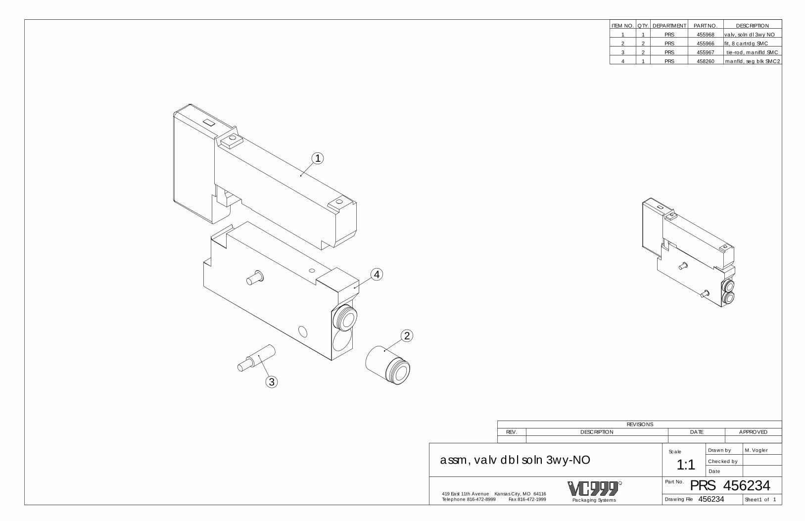
REVISIONSREV. DESCRIPTION DATE APPROVED
Packaging Systems
R
Telephone 816-472-8999 Fax 816-472-1999419 East 11th Avenue Kansas City, MO 64116
Drawn by
Date
Checked by
Scale M. Vogler
Part No.
1:1PRS 456234
assm, valv dbl soln 3wy-NO
Drawing File 456234 ofSheet1 1
1
4
2
3
ITEM NO. QTY. DEPARTMENT PART NO. DESCRIPTION1 1 PRS 455968 valv, soln dl 3wy NO2 2 PRS 455966 fit, 8 cartrdg SMC 3 2 PRS 455967 tie-rod, manifld SMC4 1 PRS 458260 manfld, seg blk SMC2

SECTION 8 - ELECTRICAL DIAGRAMS

1 2 3 4 5 6 7 8 9
1 2 3 4 5 6 7 8 9
A
B
C
D
E
F
G
H
I
A
B
C
D
E
F
G
H
I
Cover Page 00
General Information
Layout
Power
Machine Safety
Formed Film Unwind
Non Formed Film Unwind
Trim Removal
Variable Frequency Drive (VFD)
PLC Inputs
01-02
03 - 09
10 - 19
20 - 24
25 - 29
30 -34
35 - 39
40 - 44
45 -49
PLC Outputs
PLC Modules
Plugs
50 - 54
55 - 59
60 - 64
Pneumatics 65 - 69
RS42011591300c220605011507
V
Hz
A
Kw
AT
Bar
Voltage
Frequency
Current
Power
Fused Current
Air Pressure
Machine NumberType VC999 /
MADE IN USA
3Ph.,A.C.,
RS 420c
PACKAGING SYSTEMSA DIVISION OF INAUEN AG CH-9100 HERISAU
Interface Summary 70 - 75
Cover Page ELR 463 834Part #:
N/AScale:
00Sheet:
of 99RSC-PL1-A
File:TJF
Drawn By:03/2009
Date:
Cover PageSection:
419 East 11th AvenueKansas City, MO 64116Telephone: (816) 472-8999Fax: (816) 472-1999
76 - 99Reserved
Page numbering may not be consecutive(options not installed may have been removed & space has been left for future use)

1 2 3 4 5 6 7 8 9
1 2 3 4 5 6 7 8 9
A
B
C
D
E
F
G
H
I
A
B
C
D
E
F
G
H
I
ELR 463 834Part #:
N/AScale:
01Sheet:
of 99RSC-PL1-A
File:TJF
Drawn By:03/2009
Date:
General InformationSection:
419 East 11th AvenueKansas City, MO 64116Telephone: (816) 472-8999Fax: (816) 472-1999
Black High Voltage
Red 120 Volts AC
White Neutral
24 Volts DCBrown
Blue 0 Volts DC
Green/Yellow Ground
Identification
Typical:
Relay 6156CR contact is used on page 20, line 52A2A1
6156CR 2052
Typical: 2010CON Page 20, Line 10, Contactor
Typical: 20101L1 Page 20, Line 10, 1st occurance, Phase 1
Typical: 20101 Page 20, Line 10, 1st occurance
other drawing
Typical: Jump To Page 35, Line 46 of Zipper Station drawingZS- Zipper Station, SS- Seal Station, PR- Printer
Typical: 2016-1PB Page 20, Line 16, 1st occurance, Push Button
2010
same drawingTypical:
Jump To Page 20, Line 10
ZS3546
CB Circuit breaker
PS Power supply
DIS Dis-connect switch
PDB Power distribution block
FU Fuse
CON Contactor
SPS Self protected starter
BR Brake RES Resistor
POT Potentiometer
CR Control relay
PES Photo electric sensor
LP Lamp
SOL Solenoid valve
PRX Proximity sensor
TC Thermocouple
SSR Solid state relay
CS Currant sensor
VFD Variable frequency drive
DRV DC drive
MTR Motor
THS Thermal switchEXT External device (not in machine)
OIT Operator interface terminal
PLC Programmable logic controller orprogrammable logic controller module
ESM Emergency stop module
SM Safety module
MS Magnetic switch
ENC Encoder
PSW Pressure switch
CCM CC Link module
PSA Pressure switch analog
SS Safety switch
HTR Heater
SRV Servo Amplifier
PB Push button switch
DiodeDIO
XFR Control transformer
TFU Thermal fuse (cutoff)
TOR Thermal overload relay
FS Foot switch
RVS Reversing unit, self protected starter
GFI Ground fault interrupter
RHE Rheostat
FAN Fan (Cabinet)
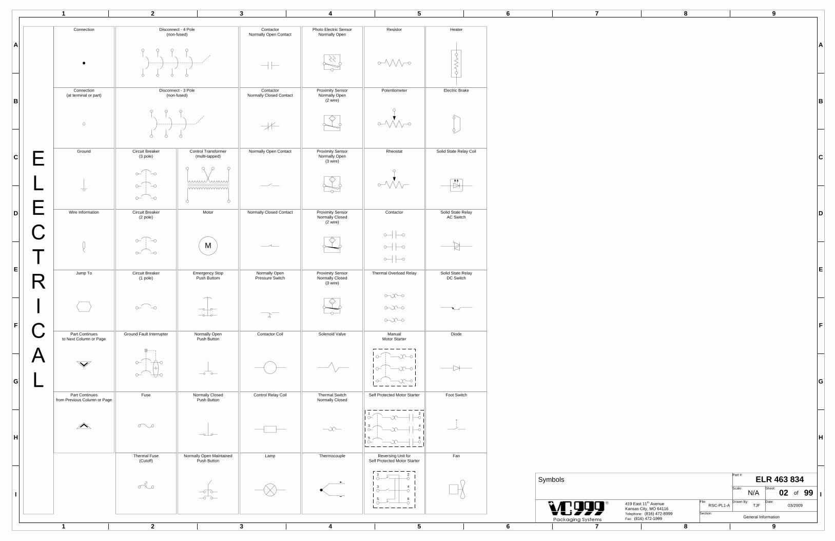
1 2 3 4 5 6 7 8 9
1 2 3 4 5 6 7 8 9
A
B
C
D
E
F
G
H
I
A
B
C
D
E
F
G
H
I
ELR 463 834Part #:
N/AScale:
02Sheet:
of 99RSC-PL1-A
File:TJF
Drawn By:03/2009
Date:
General InformationSection:
419 East 11th AvenueKansas City, MO 64116Telephone: (816) 472-8999Fax: (816) 472-1999
Connection
Connection(at terminal or part)
Wire Information
Jump To
Ground
Circuit Breaker(2 pole)
Circuit Breaker(1 pole)
ManualMotor Starter
Control Transformer(multi-tapped)
Motor
M
Proximity SensorNormally Closed
(2 wire)
Proximity SensorNormally Closed
(3 wire)
Heater
Lamp
Contactor Coil
Control Relay Coil
ContactorNormally Open Contact
ContactorNormally Closed Contact
Normally Closed Contact
Normally OpenPush Button
Normally ClosedPush Button
Emergency StopPush Buttom
Solenoid Valve
Thermocouple
Resistor
Potentiometer
Rheostat
Fuse
Proximity SensorNormally Open
(3 wire)
Normally Open Contact
Normally OpenPressure Switch
Proximity SensorNormally Open
(2 wire)
Photo Electric SensorNormally Open
1
3
5
2
4
6
Self Protected Motor StarterThermal SwitchNormally Closed
Normally Open MaintainedPush Button
Symbols
Part Continuesto Next Column or Page
Part Continuesfrom Previous Column or Page
Solid State RelayAC Switch
Solid State RelayDC Switch
Solid State Relay Coil
Diode
Reversing Unit forSelf Protected Motor Starter
1
3
5
2
4
6
Thermal Fuse(Cutoff)
Contactor
Electric Brake
Thermal Overload Relay
Ground Fault Interrupter
Disconnect - 4 Pole(non-fused)
Circuit Breaker(3 pole)
Disconnect - 3 Pole(non-fused)
Foot Switch
Fan

1 2 3 4 5 6 7 8 9
1 2 3 4 5 6 7 8 9
A
B
C
D
E
F
G
H
I
A
B
C
D
E
F
G
H
I
ELR 463 834Part #:
N/AScale:
03Sheet:
of 99RSC-PL1-A
File:TJF
Drawn By:03/2009
Date:
LayoutSection:
419 East 11th AvenueKansas City, MO 64116Telephone: (816) 472-8999Fax: (816) 472-1999
(444)
(580) (580)
(328)
(328)
(328)
(328)
Panel Wire Duct & Din Rail
108
144
311
114
374
1
5
4
7
6
6
2
180
PART # DESCRIPTIONRSA R65245 Seal cabinet back plate
REF1
ELR 450 916 Wire duct 1" x 3" with cover, white3ELR 455 626 Wire duct 1.5" x 4" with cover, white4ELR 461 099 Wire duct 1.5" x 1.5" with cover, white5
ELR 450 915 Din rail 35mm2
RSA R65413 Spacer - 20mm x 25.46FSC 450 016 M5 x 12 set screwFSC 453 247 M5 x 12 SHCSRSA R65413 Spacer - 20mm x 25.47FSC 450 016 M5 x 12 set screwFSC 450 983 M5 x 10 SHCSFSC 457 430 M6 washer8
8
(580)
374
374
374
374
(328)
3

1 2 3 4 5 6 7 8 9
1 2 3 4 5 6 7 8 9
A
B
C
D
E
F
G
H
I
A
B
C
D
E
F
G
H
I
ELR 463 834Part #:
N/AScale:
04Sheet:
of 99RSC-PL1-A
File:TJF
Drawn By:03/2008
Date:
LayoutSection:
419 East 11th AvenueKansas City, MO 64116Telephone: (816) 472-8999Fax: (816) 472-1999
BUSS BARTERM BLK
Panel Layout
1
2
4
6
9 10
29
30
3
Terminal Block 1Refer to page 06
Terminal Block 2Refer to page 06
24 25 26 27 28
Fuse BlockRefer to page 08
37
27
30
20
Y20-Y37
C
C
17
7
10
0
Y0-Y17
C
C
17
7
10
0
X0-X17
C
C
37
27
30
20
X20-X37
C
C
Fuse BlockRefer to page 08
5518SSR
Heat Zone 2(Form)
5514SSR
Heat Zone 1(Seal)
2010
ESM
2106SM1450PS
8
1410FU
1414XFR
1410FU
1417FU
A7001062VFD
2027
CO
N20
25C
ON
1011PDB
1008FU
2168
CO
N21
70C
ON
1252CB
Heat Zone 2(Form)
1244CB
Heat Zone 1(Seal)
1065
CB
VFD
FX2N-2LC
POWER
OUT1OUT2
24 V
21
5507PLC
FX2NCCNV-IF
20
MITSUBISHIMELSEC FX3UC-64MT
/D
18
1612PLC
2323
7
5
12
16
5150SPS
Vacuum Pump
11
13
5154SPS
Rotary Knife
PART # DESCRIPTIONREF1
ELR 461 918 Power distribution block 1-423
ELR 462 100 VFD, A series 1.5K, 200V4ELR 461 129 VFD encoder input board, A series
ELR 451 475 End clamp5
ELR 454 468 TransformerELR 453 827 Fuse, 3A class CCELR 453 825 Fuse, 7A class CC
8
9ELR 462 085 Buss bar, 2 stationELR 462 086 Buss bar, 3 station
10ELR 453 600 Buss bar, terminal block
ELR 453 599 Buss bar, 4 stationELR 462 079 Self protected starter, 12A base11ELR 462 080 Self protected starter, 32A baseELR 462 081 Control unit .35-1.4A, for 12A SPS
ELR 462 084 Control unit 8-32A, for 32A SPS
13
CSP 455 501 Power supply, 24VDC 5A2425 ELR 462 130 Safety switch module
ELR 462 076 Emergency stop relay module26
ELR 462 077 Solid state relay with heatsink28
ELR 461 882 Auxiliary contact, 2 NO
12
16
ELR 451 514 12mm gray terminalELR 451 932 12mm green/yellow terminal29
30ELR 451 932 12mm green/yellow terminal
PLA 462 497 Rubber grommet, 7/8" hole
ELR 453 597 Contactor, 32A 24 VDC low consumption coil
6 ELR 453 597 Contactor, 32A 24 VDC low consumption coil
ELR 451 764 Circuit breaker, 2 pole 25A27
ELR 462 000 PLC, FX3UC-6418
ELR 459 950 PLC eeprom 64KELR 462 001 PLC, battery FX3U series PLC
CSP 455 060 PLC, 16 output cardCSP 455 061 PLC, bus conversion block
1920
CSP 455 704 PLC, temperature control cardELR 456 647 PLC, high speed counter
2122
ELR 462 613 PLC, 4 channel analog input card 17
ELR 455 841 Fuse holder 60AELR 455 836 Fuse, 50A
ELR 451 624 Circuit breaker, 3 pole 20A7
ELR 462 082 Control unit 1.25-5A, for 12A SPSELR 462 083 Control unit 3-12A, for 12A SPS
1415
ELR 455 627 Terminal block, 20 pin distributionELR 462 414 Cable, 20 pin to 20 pin 1.5M
23
31ELR 456 615 Harness 5 pin female 12mm connectorELR 462 149 Vacuum sensor with hose connection

1 2 3 4 5 6 7 8 9
1 2 3 4 5 6 7 8 9
A
B
C
D
E
F
G
H
I
A
B
C
D
E
F
G
H
I
ELR 463 834Part #:
N/AScale:
06Sheet:
of 99RSC-PL1-A
File:TJF
Drawn By:03/2009
Date:
LayoutSection:
419 East 11th AvenueKansas City, MO 64116Telephone: (816) 472-8999Fax: (816) 472-1999
1
1
1
1
1
2
2
1
Common Terminal Block Standard Terminal Block
1 1
11
2 2
11
Terminal Block Layout
PART # DESCRIPTIONREF
ELR 460 265 Terminal block, double layer common1
ELR 460 180 End coverELR 460 181 Offset spacer plateELR 460 182 2 pole jumperELR 462 172 5 pole jumper
ELR 451 475 End clamp
ELR 460 265 Terminal block, double layer common2
ELR 460 180 End coverELR 460 181 Offset spacer plateELR 460 182 2 pole jumper
ELR 451 475 End clamp
ELR 460 178 Terminal block, double layer1 2
Safety SwitchF1-1
Switch locationF - FormS - Seal
Z - ZipperC - Cut
Contact1 - Brown - White2 - Blue - Black
Location Switch Number
TB1 - Power
110V A
C
Neutral
N
N
N
N
P
P
P
P
S24
S24
S24
S24
S24
S24
S24
S24
S24
S24
S24
S24
S24
S24
S24
S24
S24
S24
S24
S24
S24
S24
S24
S24
S24
S24
S24
S24
Safe 24V
DC
C24
C24
C24
C24
C24
C24
C24
C24
C24
C24
C24
C24
C24
C24
C24
C24
C24
C24
C24
C24
C24
C24
C24
C24
C24
C24
C24
C24
Constant 24V
DC
0V
0V
0V
0V
0V
0V
0V
0V
0V
0V
0V
0V
0V
0V
0V
0V
0V
0V
0V
0V
0V
0V
0V
0V
0V
0V
0V
0V
0V DC
50
50
50
50
62
65
65
62
61
64
64
61
Safety R
eset
Em
ergency Stop
60
63
63
60
10
10
10
10
11
15
15
11
12
16
16
12
13
17
17
13
14
18
18
14
Safety Zone 2 (Seal)
S1-2 S3-2
S3-1S1-1
S4-1
S2-2 S4-2
S2-1P
S
S
1
1
1
1
2
6
6
2
3
7
7
3
4
8
8
4
5
9
9
5
Safety Zone 1 (Form
)
F1-1
F1-2
F3-1
F3-2
F2-1
F2-2
F4-1
F4-2
P
S
S20
20
20
20
Safety Zone 4 (not used)
S
S
P
30
30
30
30
31
36
36
31
32
37
37
32
33
38
38
33
35
40
40
35
Safety Zone 3 (C
ut)
C2-2
C3-1C1-1
C2-1P S
S
E1-1
E1-2
E2-1
S
E2-2
S
P
P
TB2 - Safety
FormSealCut
F4 F2
F1F3
S4 S2
S1S3C3C1
C4C2
Utility Side
Operator Side
Safety Switch Location
34
39
39
34
C5-2
C5-1
C4-2
C3-2C1-2
C4-1
0V
0V
0V
0V
ELR 463 839 Terminal label set RSC--
C5
C9 cover on revolving trim removal

1 2 3 4 5 6 7 8 9
1 2 3 4 5 6 7 8 9
A
B
C
D
E
F
G
H
I
A
B
C
D
E
F
G
H
I
Relay Block LayoutFuse Block Layout
ELR 463 834Part #:
N/AScale:
08Sheet:
of 99RSC-PL1-A
File:TJF
Drawn By:03/2009
Date:
LayoutSection:
419 East 11th AvenueKansas City, MO 64116Telephone: (816) 472-8999Fax: (816) 472-1999
Relay Block
0V DC (Blue)
110V AC (Gray)24V DC (Red)
0V DC
24V DC
110V
0V DC (Blue)
110V AC (Gray)24V DC (Red)
0V DC
24V DC
110V
Buss Bar Colors
PART # DESCRIPTIONREF1 ELR 451 475 End clamp2 ELR 460242 Relay, 1pdt
ELR 460244 Relay, optocouplerELR 460 267 Relay separator plateELR 460 268 Relay bridge jumper blueELR 460 269 Relay bridge jumper redELR 462 173 Relay bridge jumper gray
ELR 462 186 Relay, 2pdt345678
Buss Bar Colors
Fuse Block
9 ELR 462 075 Fuse block, 5 x 20
ELR 460 182 2 pole jumperELR 462 223 Fuse, 1A 5x20
1
Form station safety2153CR2
Seal station safety2155CR2
Cutting station safety2157CR2
Safety circuit reset5156CR2
Heater control5160CR3
Seal station spindle brake5018SSR4
Form station spindle brake5008SSR4
5152CR Trim removal - revolving2
5
5
5
Relay Terminal JumpersRight Side - ContactsN.O.COM
--110
0V--
0V--
----
----
----
--0V
--0V
--0V60V D
C
0V DC
6
Relay Terminal JumpersLeft Side - Coil A2-A1+
7
OV--
0V--
0V--
0V DC
6
--C24
--C24
--C24
--C24
24V D
C
--S24
Emergency stop module power2017FU2144FU Safety module power2023FU Safety contactor coil
92025FU E-stop contactor coil5070FU Common Y0-Y175170FU Common Y20-Y37
1

Transport Chain1.10kWM
10652L1
10652L2
10652L3
4-12ga. Cable
- 01 -
1 2 3 4 5 6 7 8 9
1 2 3 4 5 6 7 8 9
A
B
C
D
E
F
G
H
I
A
B
C
D
E
F
G
H
I
3 Phase Power - Motors 1 ELR 463 834Part #:
N/AScale:
10Sheet:
of 99RSC-PL1-A
File:TJF
Drawn By:03/2009
Date:
PowerSection:
419 East 11th AvenueKansas City, MO 64116Telephone: (816) 472-8999Fax: (816) 472-1999
- 02 -
- 03 -
- 04 -
- 05 -
- 06 -
- 07 -
- 08 -
- 09 -
- 10 -
- 11 -
- 12 -
- 13 -
- 14 -
- 15 -
- 16 -
- 17 -
- 18 -
- 19 -
- 20 -
- 21 -
- 22 -
- 23 -
- 24 -
- 25 -
- 26 -
- 27 -
- 28 -
- 29 -
- 30 -
- 31 -
- 32 -
- 33 -
- 34 -
- 35 -
- 36 -
- 37 -
- 38 -
- 39 -
- 40 -
- 41 -
- 42 -
- 43 -
- 44 -
- 45 -
- 46 -
- 47 -
- 48 -
- 49 -
- 50 -
- 51 -
- 52 -
- 53 -
- 54 -
- 55 -
- 56 -
- 57 -
- 58 -
- 59 -
- 60 -
- 61 -
- 62 -
- 63 -
- 64 -
- 65 -
- 66 -
- 67 -
- 68 -
- 69 -
- 70 -
- 71 -
- 72 -
- 73 -
- 74 -
- 75 -
- 76 -
1201 1201 1201
Refer to Data PlatePage 0
10091L1 10091L2 10091L3
6ga. BLACK
10201L1 10201L2 10201L3
10061L1 10061L2 10061L3
10251L1 10251L2 10251L3
1037 10371037
10121L1 10121L2 10121L3
8ga. Black
10121L1 10121L2 10121L3
10251L1 10251L2 10251L3
104110411041
10251L1 10251L2 10251L3
8ga. Black
10121L1 10121L2 10121L3
1011PDB
1008FU
1004DS
2170CON
2 4 6
1 3 5
2168CON
1 3 5
2 4 6
END END END
1
PART # DESCRIPTIONREFELA 500 919 Main power switch1
ELR 451 217 Rotary knife motor (siemans 0.2kW)2
ELR 454 405 Cable, 4 conductor 18ga. black4ELR 451 204 Cable, 4 conductor 12ga. gray5
Rotary Knife0.20kWM
10451L1
10451L2
10451L3
4-18ga. cable5154SPS
1
3
5
2
4
6
2
1045MTR
4
Vacuum Pump3.00kWM
10501L1
10501L2
10501L3
4-12ga. Cable5150SPS
1
3
5
2
4
6
1050MTR
5
5
12ga. Black
Variable Frequency Drive
1062VFD
10651L1
10651L2
10651L3
12ga. Black
T
S
R
R1
S1
10251L1
10251L2
10251L3
1065CB
2
4
6
1
3
5
12ga. Green/Yellow
W
V
U
3
1065MTR
CSP 454 537 Motor, advance 1.5hp3CSP 455 145 Encoder, single channel
ELA 516 651 Cover (2 required)

- 01 -
1 2 3 4 5 6 7 8 9
1 2 3 4 5 6 7 8 9
A
B
C
D
E
F
G
H
I
A
B
C
D
E
F
G
H
I
3 Phase Power - Heaters ELR 463 834Part #:
N/AScale:
12Sheet:
of 99RSC-PL1-A
File:TJF
Drawn By:03/2009
Date:
PowerSection:
419 East 11th AvenueKansas City, MO 64116Telephone: (816) 472-8999Fax: (816) 472-1999
- 02 -
- 03 -
- 04 -
- 05 -
- 06 -
- 07 -
- 08 -
- 09 -
- 10 -
- 11 -
- 12 -
- 13 -
- 14 -
- 15 -
- 16 -
- 17 -
- 18 -
- 19 -
- 20 -
- 21 -
- 22 -
- 23 -
- 24 -
- 25 -
- 26 -
- 27 -
- 28 -
- 29 -
- 30 -
- 31 -
- 32 -
- 33 -
- 34 -
- 35 -
- 36 -
- 37 -
- 38 -
- 39 -
- 40 -
- 41 -
- 42 -
- 43 -
- 44 -
- 45 -
- 46 -
- 47 -
- 48 -
- 49 -
- 50 -
- 51 -
- 52 -
- 53 -
- 54 -
- 55 -
- 56 -
- 57 -
- 58 -
- 59 -
- 60 -
- 61 -
- 62 -
- 63 -
- 64 -
- 65 -
- 66 -
- 67 -
- 68 -
- 69 -
- 70 -
- 71 -
- 72 -
- 73 -
- 74 -
- 75 -
- 76 -
1401 1401 1401
12101L1 12101L2 12101L3
12151L1 12151L2 12151L3
1227 12271227
8ga. Black
10121L1 10121L2 10121L3
12151L1 12151L2 12151L3
124112411241
12151L1 12151L2 12151L3
1040 10401040
10121L1 10121L2 10121L3
10121L1 10121L2 10121L3
2025CON
2 4 6
1 3 5
2027CON
1 3 5
2 4 6
END ENDEND
12441L1
12451L2
12ga. Black
12442L1
1244CB
4
2
3
1
Heat Zone 1(Seal)
12ga. Green
1246HTR
5514SSR
1/L1 2/T112151L1
12151L2
12521L3
12531L1
12ga. Black
12522L3
1252CB
4
2
3
1
Heat Zone 2(Form)
12ga. Green
1254HTR
5518SSR
1/L1 2/T112151L3
12151L1
8ga. Black
10ga. Black
10ga. Black
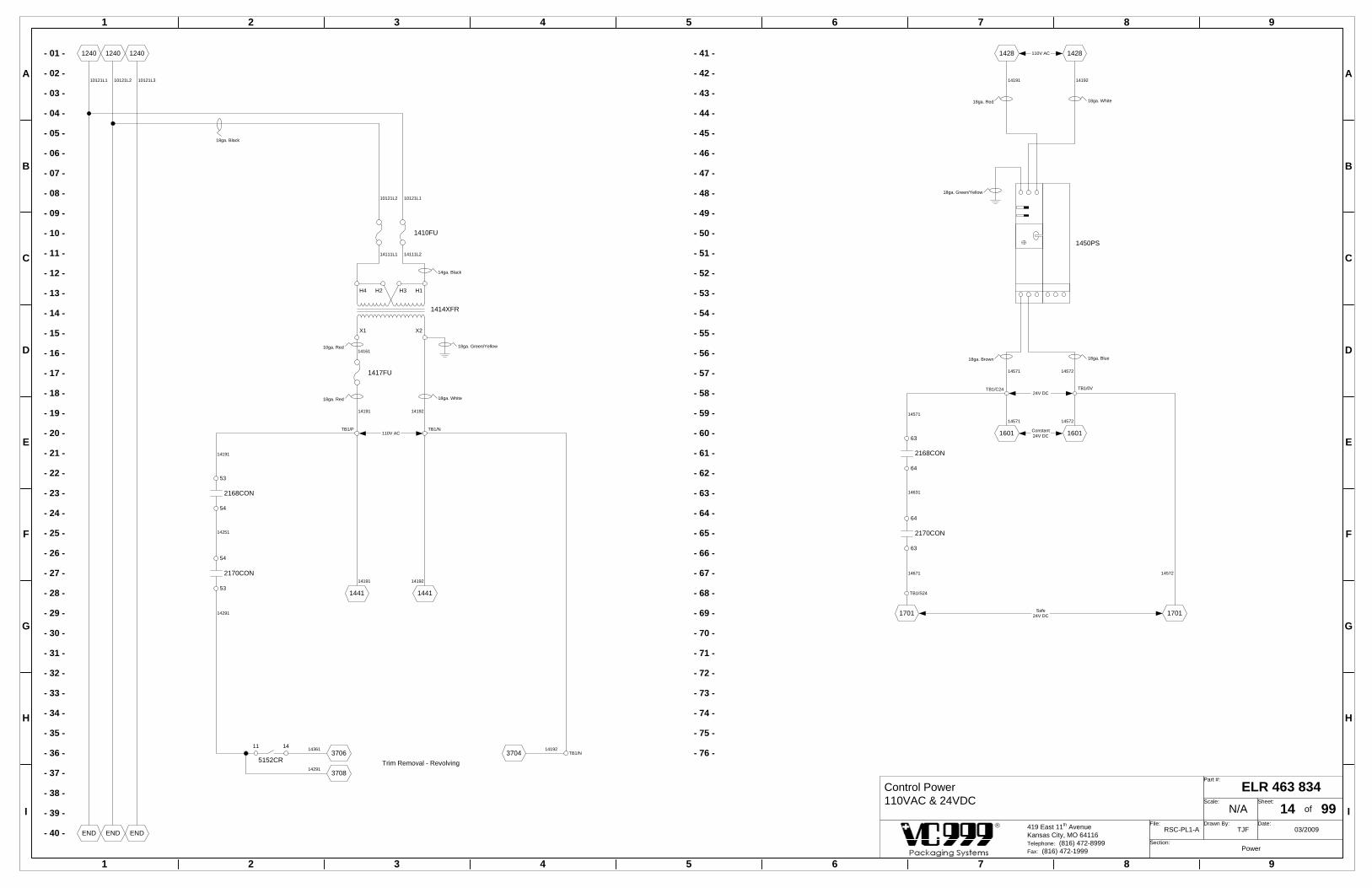
2168CON
2170CON
54
53
53
54
14191
14251
14291
- 01 -
1 2 3 4 5 6 7 8 9
1 2 3 4 5 6 7 8 9
A
B
C
D
E
F
G
H
I
A
B
C
D
E
F
G
H
I
Control Power110VAC & 24VDC
ELR 463 834Part #:
N/AScale:
14Sheet:
of 99RSC-PL1-A
File:TJF
Drawn By:03/2009
Date:
PowerSection:
419 East 11th AvenueKansas City, MO 64116Telephone: (816) 472-8999Fax: (816) 472-1999
- 02 -
- 03 -
- 04 -
- 05 -
- 06 -
- 07 -
- 08 -
- 09 -
- 10 -
- 11 -
- 12 -
- 13 -
- 14 -
- 15 -
- 16 -
- 17 -
- 18 -
- 19 -
- 20 -
- 21 -
- 22 -
- 23 -
- 24 -
- 25 -
- 26 -
- 27 -
- 28 -
- 29 -
- 30 -
- 31 -
- 32 -
- 33 -
- 34 -
- 35 -
- 36 -
- 37 -
- 38 -
- 39 -
- 40 -
- 41 -
- 42 -
- 43 -
- 44 -
- 45 -
- 46 -
- 47 -
- 48 -
- 49 -
- 50 -
- 51 -
- 52 -
- 53 -
- 54 -
- 55 -
- 56 -
- 57 -
- 58 -
- 59 -
- 60 -
- 61 -
- 62 -
- 63 -
- 64 -
- 65 -
- 66 -
- 67 -
- 68 -
- 69 -
- 70 -
- 71 -
- 72 -
- 73 -
- 74 -
- 75 -
- 76 -
END END END
18ga. Black
1240 12401240
10121L1 10121L2 10121L3
1410FU
14111L214111L1
110V AC
1417FU
10121L2 10121L1
14192
14161
14191
14ga. Black
10ga. Red
18ga. White18ga. Red
18ga. Green/Yellow
TB1/P16011601
24V DC
1457214571
18ga. Blue18ga. Brown
TB1/0VTB1/C24
2168CON
2170CON
1701
64
63
63
64
14281428
14191 14192
110V AC
18ga. Green/Yellow
14571
14631
14671
TB1/S24
1450PS
18ga. White18ga. Red
14411441
1419214191
1701
1457214571
Safe24V DC
Constant24V DC
14572
3704Trim Removal - Revolving
TB1/N14192
5152CR
14113706
3708
14361
14291
TB1/N
H4 H2 H3 H1
X1 X2
1414XFR

- 01 -
1 2 3 4 5 6 7 8 9
1 2 3 4 5 6 7 8 9
A
B
C
D
E
F
G
H
I
A
B
C
D
E
F
G
H
I
- 02 -
- 03 -
- 04 -
- 05 -
- 06 -
- 07 -
- 08 -
- 09 -
- 10 -
- 11 -
- 12 -
- 13 -
- 14 -
- 15 -
- 16 -
- 17 -
- 18 -
- 19 -
- 20 -
- 21 -
- 22 -
- 23 -
- 24 -
- 25 -
- 26 -
- 27 -
- 28 -
- 29 -
- 30 -
- 31 -
- 32 -
- 33 -
- 34 -
- 35 -
- 36 -
- 37 -
- 38 -
- 39 -
- 40 -
- 41 -
- 42 -
- 43 -
- 44 -
- 45 -
- 46 -
- 47 -
- 48 -
- 49 -
- 50 -
- 51 -
- 52 -
- 53 -
- 54 -
- 55 -
- 56 -
- 57 -
- 58 -
- 59 -
- 60 -
- 61 -
- 62 -
- 63 -
- 64 -
- 65 -
- 66 -
- 67 -
- 68 -
- 69 -
- 70 -
- 71 -
- 72 -
- 73 -
- 74 -
- 75 -
- 76 -
24V DC
14571 14572
18ga. Brown 18ga. Blue
1460 1460
16411641
24V DC
14571 14572
18ga. Brown 18ga. Blue
1640 1640
ENDEND
24VDC (Constant Power) ELR 463 834Part #:
N/AScale:
16Sheet:
of 99RSC-PL1-A
File:TJF
Drawn By:03/2009
Date:
PowerSection:
419 East 11th AvenueKansas City, MO 64116Telephone: (816) 472-8999Fax: (816) 472-1999
MITSUBISHIMELSEC FX3UC-64MT
/D
TB1/C24
TB1/0V
INPUT24VDC
+ - FG
14571
14572
0V24V 24V 0V
PART # DESCRIPTIONREF
ELR 460 796 Comm. Cable, OIT - PLC 1m (cabinet)ELR 461 644 CF memory cardELR 460 795 Operator Interface Terminal (5.7" color)1
ELR 460 797 Comm. Cable, OIT - PLC 10m (swing arm)
1
2
2
2001TB1/C2414571
2001 TB1/0V14572
Emergency Stop & Safety Modules
2601TB1/C2414571
2601 TB1/0V14572
Formed Film Unwind (Top)
3001TB1/C2414571
3001 TB1/0V14572
Non-Formed Film Unwind - Seal Station
4501TB1/C2414571
4501 TB1/0V14572
PLC Inputs
1609OIT
1612PLC
5501TB1/C2414571
5501 TB1/0V14572
PLC Modules5601TB1/C2414571
5601 TB1/0V14572
5701TB1/C2414571
5701 TB1/0V14572
Water Valve
1657SOL
14571 16571TB1/C24 TB1/0V
14572
5160CR
2421
TB1/0V14572
Add Jumperwith Water Chiller
22
4148TB1/C2414571
4149 TB1/0V14572
VFD4122 TB1/0V
145724121TB1/C24
14571
5005TB1/C2414571
PLC Outputs

- 01 -
1 2 3 4 5 6 7 8 9
1 2 3 4 5 6 7 8 9
A
B
C
D
E
F
G
H
I
A
B
C
D
E
F
G
H
I
- 02 -
- 03 -
- 04 -
- 05 -
- 06 -
- 07 -
- 08 -
- 09 -
- 10 -
- 11 -
- 12 -
- 13 -
- 14 -
- 15 -
- 16 -
- 17 -
- 18 -
- 19 -
- 20 -
- 21 -
- 22 -
- 23 -
- 24 -
- 25 -
- 26 -
- 27 -
- 28 -
- 29 -
- 30 -
- 31 -
- 32 -
- 33 -
- 34 -
- 35 -
- 36 -
- 37 -
- 38 -
- 39 -
- 40 -
- 41 -
- 42 -
- 43 -
- 44 -
- 45 -
- 46 -
- 47 -
- 48 -
- 49 -
- 50 -
- 51 -
- 52 -
- 53 -
- 54 -
- 55 -
- 56 -
- 57 -
- 58 -
- 59 -
- 60 -
- 61 -
- 62 -
- 63 -
- 64 -
- 65 -
- 66 -
- 67 -
- 68 -
- 69 -
- 70 -
- 71 -
- 72 -
- 73 -
- 74 -
- 75 -
- 76 -
24V DC
14671 14572
18ga. Brown 18ga. Blue
1469 1469
17411741
24V DC
14671 14572
18ga. Brown 18ga. Blue
1740 1740
ENDEND
24VDC (Safe Power) ELR 463 834Part #:
N/AScale:
17Sheet:
of 99RSC-PL1-A
File:TJF
Drawn By:03/2009
Date:
PowerSection:
419 East 11th AvenueKansas City, MO 64116Telephone: (816) 472-8999Fax: (816) 472-1999
24V 0V 24V 0V
5001TB1/S2414671
5001 TB1/0V14572
PLC Outputs

- 01 -
1 2 3 4 5 6 7 8 9
1 2 3 4 5 6 7 8 9
A
B
C
D
E
F
G
H
I
A
B
C
D
E
F
G
H
I
Emergency Stop Module ELR 463 834Part #:
N/AScale:
20Sheet:
of 99RSC-PL1-A
File:TJF
Drawn By:03/2009
Date:
Machine SafetySection:
419 East 11th AvenueKansas City, MO 64116Telephone: (816) 472-8999Fax: (816) 472-1999
- 02 -
- 03 -
- 04 -
- 05 -
- 06 -
- 07 -
- 08 -
- 09 -
- 10 -
- 11 -
- 12 -
- 13 -
- 14 -
- 15 -
- 16 -
- 17 -
- 18 -
- 19 -
- 20 -
- 21 -
- 22 -
- 23 -
- 24 -
- 25 -
- 26 -
- 27 -
- 28 -
- 29 -
- 30 -
- 31 -
- 32 -
- 33 -
- 34 -
- 35 -
- 36 -
- 37 -
- 38 -
- 39 -
- 40 -
- 41 -
- 42 -
- 43 -
- 44 -
- 45 -
- 46 -
- 47 -
- 48 -
- 49 -
- 50 -
- 51 -
- 52 -
- 53 -
- 54 -
- 55 -
- 56 -
- 57 -
- 58 -
- 59 -
- 60 -
- 61 -
- 62 -
- 63 -
- 64 -
- 65 -
- 66 -
- 67 -
- 68 -
- 69 -
- 70 -
- 71 -
- 72 -
- 73 -
- 74 -
- 75 -
- 76 -
24V DC
14571 14572
18ga. Brown 18ga. Blue
1621 1621
20412041
24V DC
14571 14572
18ga. Brown 18ga. Blue
2040 2040
21012101
TB1/0V14572
TB1/0V14572
4622
2058
TB1/C2414571
TB1/C2414571
20581
X27
20251
Emergency Stop Module2010ESM
14
24
13
23
34
42
33
41
TB1/C2414571
TB1/0V14572
20131
20151
20132
20152
START S34S33
POWER A2A1
CHANNEL 2 S22S21
CHANNEL 1 S12S11
A2A1Heater Contactor 1
2025CON
A2A1Heat Contactor 2
2027CON
2017FU
2025FU5160CR
14 11
24V 0V 24V 0V
1
ELR 462 496 Emergency stop switch w/2 NC contactsPART # DESCRIPTIONREF
1
120820522054
121320522054
20171
20252 20253
18ga. Brown
18ga. Blue
18ga. Brown
18ga. Blue
Green White
Black Red1
1
2
2
Wire Color
TB2/50
2019TB2/50
2131
20581
TB2/50 2132
5156CR
14112052
20524 20581
20581
20581
20521
20541
20522 20523
2025CON
22 21
2027CON
21 22
2025CON
14 13
2027CON
13 14
2168CON
21 22
2170CON
22 212058
20524
216120232
TB1/C2414571
TB1/24V14571
SealE-Stop
1
1
2
2
FormE-Stop
1
1
2
2
2006-1PB 2006-2PB
TB2/62
TB2/65
TB2/60
TB2/63 20061
20071TB2/61
TB2/64
TB1/C2414571
2023FU
20231

21171
TB2/36 21181
TB2/31 21174
TB2/39
TB2/34
21184
21175TB2/35
21185TB2/40
TB2/3021161
21161
21172
TB2/37 21182
TB2/32 21173
TB2/38 21183
TB2/332
21161
1
2117-2SS2117-1SS
5
2117-5SS
1457221571 A2A1
2157CR
Cut Safety
462018ga. Brown
1457221551 A2A1
2155CR
Seal Safety
461818ga. Brown
1457221531 A2A1
2153CR
Form Safety
461618ga. Brown
- 01 -
1 2 3 4 5 6 7 8 9
1 2 3 4 5 6 7 8 9
A
B
C
D
E
F
G
H
I
A
B
C
D
E
F
G
H
I
Safety Module ELR 463 834Part #:
N/AScale:
21Sheet:
of 99RSC-PL1-A
File:TJF
Drawn By:03/2009
Date:
Machine SafetySection:
419 East 11th AvenueKansas City, MO 64116Telephone: (816) 472-8999Fax: (816) 472-1999
- 02 -
- 03 -
- 04 -
- 05 -
- 06 -
- 07 -
- 08 -
- 09 -
- 10 -
- 11 -
- 12 -
- 13 -
- 14 -
- 15 -
- 16 -
- 17 -
- 18 -
- 19 -
- 20 -
- 21 -
- 22 -
- 23 -
- 24 -
- 25 -
- 26 -
- 27 -
- 28 -
- 29 -
- 30 -
- 31 -
- 32 -
- 33 -
- 34 -
- 35 -
- 36 -
- 37 -
- 38 -
- 39 -
- 40 -
- 41 -
- 42 -
- 43 -
- 44 -
- 45 -
- 46 -
- 47 -
- 48 -
- 49 -
- 50 -
- 51 -
- 52 -
- 53 -
- 54 -
- 55 -
- 56 -
- 57 -
- 58 -
- 59 -
- 60 -
- 61 -
- 62 -
- 63 -
- 64 -
- 65 -
- 66 -
- 67 -
- 68 -
- 69 -
- 70 -
- 71 -
- 72 -
- 73 -
- 74 -
- 75 -
- 76 -
24V DC
14571 14572
18ga. Brown 18ga. Blue
2076 2076
21412141
24V DC
14571 14572
18ga. Brown 18ga. Blue
TB1/C2414571
2140 2140
ENDEND
TB1/0V14572
21621
21641
21661
2060
2062
20581
20581
Plug 1
Plug 3
Safety Module Plug Key
Plug 4
Plug 5
Plug 7
Plug 6
Plug 8
Plug 1
Plug Receptacle
Plug 2
Plug 3
Plug 4
Plug 5
Plug 6
Plug 7
Plug 8
Plug 2
24V 0V 24V 0V
1
ELR 462 475 Safety switch, 2NO contacts with M8 connectorPART # DESCRIPTIONREF
1
2144FU
TB2/121081
21081
21091
TB2/6 21101
TB2/2 21092
TB2/7 21102
TB2/3 21093
TB2/8 21103
TB2/4 21094TB2/5
21104TB2/9
22 3 41
21081
2109-4SS2109-3SS2109-2SS2109-1SS
21134TB2/14
21144TB2/18
TB2/1021121
21121
21131
TB2/15 21141
TB2/11 21132
TB2/16 21142
TB2/12 21133
TB2/17 21143
TB2/1322 3 41
21121
2113-4SS2113-3SS2113-2SS2113-1SS
TB2/2021241
21241
21241
8
7
6
16
15
14
2
5
24
23
22
32
30
31
13
21
29
SENSOR 1Forming
SENSOR 2Sealing
SENSOR 3Cutting
SENSOR 4Not Used
START 3-4
Safety Module2106SM
START 1-2
1
25
26
24v DC
STANDBY
9
17
SAFETY OUTPUT 1
10
18
SAFETY OUTPUT 2
3
4
OUTPUT S1
11
19
SAFETY OUTPUT 3
OUTPUT S2
12
20
SAFETY OUTPUT 4
27
28
OUTPUT S3
OUTPUT S4
18ga. Brown
18ga. Brown
18ga. Brown
18ga. Brown
21481
All dip switches are in the off
position ELR 462 603 Harness, 4 pin 8mm connector, 10M
Blue Black
Brown White
Wire ColorM8 Connector
1
202320232
21681
18ga. Brown
18ga. Brown
A2A1Safety Contactor 1
2170CON102314271465
20524656
A2A1Safety Contactor 1
2168CON101814231461
20524656
21681
21681
TB1/0V14572
Refer to page 06 for switch location

- 01 -
1 2 3 4 5 6 7 8 9
1 2 3 4 5 6 7 8 9
A
B
C
D
E
F
G
H
I
A
B
C
D
E
F
G
H
I
ELR 463 834Part #:
N/AScale:
26Sheet:
of 99RSC-PL1-A
File:TJF
Drawn By:03/2009
Date:
Formed Film UnwindSection:
419 East 11th AvenueKansas City, MO 64116Telephone: (816) 472-8999Fax: (816) 472-1999
- 02 -
- 03 -
- 04 -
- 05 -
- 06 -
- 07 -
- 08 -
- 09 -
- 10 -
- 11 -
- 12 -
- 13 -
- 14 -
- 15 -
- 16 -
- 17 -
- 18 -
- 19 -
- 20 -
- 21 -
- 22 -
- 23 -
- 24 -
- 25 -
- 26 -
- 27 -
- 28 -
- 29 -
- 30 -
- 31 -
- 32 -
- 33 -
- 34 -
- 35 -
- 36 -
- 37 -
- 38 -
- 39 -
- 40 -
- 41 -
- 42 -
- 43 -
- 44 -
- 45 -
- 46 -
- 47 -
- 48 -
- 49 -
- 50 -
- 51 -
- 52 -
- 53 -
- 54 -
- 55 -
- 56 -
- 57 -
- 58 -
- 59 -
- 60 -
- 61 -
- 62 -
- 63 -
- 64 -
- 65 -
- 66 -
- 67 -
- 68 -
- 69 -
- 70 -
- 71 -
- 72 -
- 73 -
- 74 -
- 75 -
- 76 -
24V DC
14571 14572
18ga. Brown 18ga. Blue
1625 1625
ENDEND
TB1/0V
TB1/0V
TB1/C24
TB1/C24
Harness
Electrical Cabinet
Red
Black
White
Green
TB1/C24
TB1/0V
PLC Y0
5008SSR - 13
2608PRX - brown2615BR - blue
2608PRX - blue
2608PRX - black
2615BR - black
Brake Cover Box
Wire Color Connection
Red
Black
White
Green
Wire ColorConnection
4 x 18ga. CABLE
Y0
26151SPINDLE BRAKE
BLACK
BLUE
BLACKBLUE
BROWN
2608PRX
2615BR
14571
14571
14572
14572
2
1
3
24V
PART # DESCRIPTIONREFELR 453 714 Sensor, prox switch 12mm1
2 ELR 451 588 24VDC Brake3 ELR 451 319 Cable, 4 conductor 18ga. gray
5009
Formed Film Unwind - Upper
5008SSR
13+14

- 01 -
1 2 3 4 5 6 7 8 9
1 2 3 4 5 6 7 8 9
A
B
C
D
E
F
G
H
I
A
B
C
D
E
F
G
H
I
ELR 463 834Part #:
N/AScale:
30Sheet:
of 99RSC-PL1-A
File:TJF
Drawn By:03/2009
Date:
Non Formed Film UnwindSection:
419 East 11th AvenueKansas City, MO 64116Telephone: (816) 472-8999Fax: (816) 472-1999
- 02 -
- 03 -
- 04 -
- 05 -
- 06 -
- 07 -
- 08 -
- 09 -
- 10 -
- 11 -
- 12 -
- 13 -
- 14 -
- 15 -
- 16 -
- 17 -
- 18 -
- 19 -
- 20 -
- 21 -
- 22 -
- 23 -
- 24 -
- 25 -
- 26 -
- 27 -
- 28 -
- 29 -
- 30 -
- 31 -
- 32 -
- 33 -
- 34 -
- 35 -
- 36 -
- 37 -
- 38 -
- 39 -
- 40 -
- 41 -
- 42 -
- 43 -
- 44 -
- 45 -
- 46 -
- 47 -
- 48 -
- 49 -
- 50 -
- 51 -
- 52 -
- 53 -
- 54 -
- 55 -
- 56 -
- 57 -
- 58 -
- 59 -
- 60 -
- 61 -
- 62 -
- 63 -
- 64 -
- 65 -
- 66 -
- 67 -
- 68 -
- 69 -
- 70 -
- 71 -
- 72 -
- 73 -
- 74 -
- 75 -
- 76 -
24V DC
14571 14572
18ga. Brown 18ga. Blue
1629 1629
ENDEND
TB1/0V14572 Harness
Electrical Cabinet
Red
Black
White
Green
TB1/C24
TB1/0V
PLC X13
5018SSR- 13
4554PRX - brown3008BR - blue
4554PRX - blue
4554PRX - black
3008BR - black
Brake Cover Box
Wire Color Connection
Red
Black
White
Green
Wire ColorConnection
4 x 18ga. CABLE
TB1/C2414571
30081SPINDLE BRAKE
BLACK
BLUE
3008BR
24V 0V
1
2
PART # DESCRIPTIONREF12
Non-Formed Film Unwind - Seal Station
ELR 451 588 24VDC BrakeELR 451 319 Cable, 4 conductor 18ga. gray
5018SSR
13+14

- 01 -
1 2 3 4 5 6 7 8 9
1 2 3 4 5 6 7 8 9
A
B
C
D
E
F
G
H
I
A
B
C
D
E
F
G
H
I
ELR 463 834Part #:
N/AScale:
37Sheet:
of 99RSC-PL1-A
File:TJF
Drawn By:03/2009
Date:
Trim RemovalSection:
419 East 11th AvenueKansas City, MO 64116Telephone: (816) 472-8999Fax: (816) 472-1999
- 02 -
- 03 -
- 04 -
- 05 -
- 06 -
- 07 -
- 08 -
- 09 -
- 10 -
- 11 -
- 12 -
- 13 -
- 14 -
- 15 -
- 16 -
- 17 -
- 18 -
- 19 -
- 20 -
- 21 -
- 22 -
- 23 -
- 24 -
- 25 -
- 26 -
- 27 -
- 28 -
- 29 -
- 30 -
- 31 -
- 32 -
- 33 -
- 34 -
- 35 -
- 36 -
- 37 -
- 38 -
- 39 -
- 40 -
- 41 -
- 42 -
- 43 -
- 44 -
- 45 -
- 46 -
- 47 -
- 48 -
- 49 -
- 50 -
- 51 -
- 52 -
- 53 -
- 54 -
- 55 -
- 56 -
- 57 -
- 58 -
- 59 -
- 60 -
- 61 -
- 62 -
- 63 -
- 64 -
- 65 -
- 66 -
- 67 -
- 68 -
- 69 -
- 70 -
- 71 -
- 72 -
- 73 -
- 74 -
- 75 -
- 76 -
Electrical Cabinet
Red
Black
White
Green
5152CR - 14
TB1/P
TB1/N
Ground
Terminal 3
Terminal 2
Terminal 4
Terminal 1
Drive Control Box
Wire Color Connection
Red
Black
White
Green
Wire ColorConnection
4-18ga. Cable
3708PB
13 14
FUSE
5A
FUSE
1A
DECEL
ACCEL
MAX MIN CL IR
.25OHM
L2
A-
I2
I1
M 3715MTR
3713DRVDC Drive
32
4
1
Drive Control Box
MANUAL OVERRIDE
Drive Calibration
Connect a DC ammeter in series with the motor lead
Set the CL trimpot fully counterclockwise
Lock the motor shaft and turn the power switch on
Rotate the CL trimpot clockwise to set maximum output current to 800 milliamps
Reconnect motor leads and use a tackometer to set the min trimpot to 180 motor RPM
Set all other trimpots as shown in the illistration (to the right).2
PART # DESCRIPTION
ELR 461 008 Switch, blue momentary NO
REFELR 460 137 Assembly, complete control box1
2ELR 452 577 DC motor control board3
ELR 455 846 Fuse 1AELR 455 846 Fuse 5A4
5ELR 451 932 Terminal, 12mm ground6ELR 451 472 Terminal, 6mm gray
ELR 453 147 Strain relief, M16 x 1.5ELR 451 477 Terminal end plate
7
FUSE
5A
FUSE
1A
DECEL
ACCEL
MAX MIN CL IR
.25OHM
L2
A-
I2
I1
234
1
Drive Control Box1
2
3
4 5
6
7
1436
1436
14192
14361
143714291
1
Trim Removal - Revolving
ELR 452 576 Geared motor 1/15HP12 ELR 454 405 Cable, 4 conductor 18ga. black
PART # DESCRIPTIONREF

- 01 -
1 2 3 4 5 6 7 8 9
1 2 3 4 5 6 7 8 9
A
B
C
D
E
F
G
H
I
A
B
C
D
E
F
G
H
I
ELR 463 834Part #:
N/AScale:
40Sheet:
of 99RSC-PL1-A
File:TJF
Drawn By:03/2009
Date:
Variable Frequency Drive (VFD)Section:
419 East 11th AvenueKansas City, MO 64116Telephone: (816) 472-8999Fax: (816) 472-1999
- 02 -
- 03 -
- 04 -
- 05 -
- 06 -
- 07 -
- 08 -
- 09 -
- 10 -
- 11 -
- 12 -
- 13 -
- 14 -
- 15 -
- 16 -
- 17 -
- 18 -
- 19 -
- 20 -
- 21 -
- 22 -
- 23 -
- 24 -
- 25 -
- 26 -
- 27 -
- 28 -
- 29 -
- 30 -
- 31 -
- 32 -
- 33 -
- 34 -
- 35 -
- 36 -
- 37 -
- 38 -
- 39 -
- 40 -
- 41 -
- 42 -
- 43 -
- 44 -
- 45 -
- 46 -
- 47 -
- 48 -
- 49 -
- 50 -
- 51 -
- 52 -
- 53 -
- 54 -
- 55 -
- 56 -
- 57 -
- 58 -
- 59 -
- 60 -
- 61 -
- 62 -
- 63 -
- 64 -
- 65 -
- 66 -
- 67 -
- 68 -
- 69 -
- 70 -
- 71 -
- 72 -
- 73 -
- 74 -
- 75 -
- 76 -
Control Connections
Power ConnectionsEMF Filter ONEMF Filter OFF
Move jumper to turn on EMF Filter
VFD PARAMETERS
Encoder Board
Manufacturer Settings1 = OFF2 = OFF
Terminating Resistor1 = OFF2 = OFF3 = OFF4 = OFF
Encoder SpecificationIn line with marks
Terminal Inputset jumper to
SINK
SOU
RC
E
SIN
K
Back ofcontrol connection board
Encoder board
VFD Hardware & Parameters
71 13 Applied motor80 1.10 Motor capacity81 4 Number of motor poles
Parameter SETTING DESCRIPTION
84 60 Motor rated frequency95 1 Online auto tune96 101 Auto tuning setting
ALLC 1 All clear
83 200 Motor rated voltage
Parameter SETTING DESCRIPTION
Auto Tuning
Press mode key twicepress forward key
donepress stop key
Display “101”Display “102” drive is tuningDisplay “103”Tuning complete
Enter parameters after tuning is complete
3 60 Base frequency
182 68
AU terminal function selection (OH)183 23 RT terminal function selection (servo-on)184 7
FU terminal function selection (in position)
* Parameters not listed are set to factor default
196 11251 1 Output phase failure protection selection291 100 Jog terminal function selection (pulse train)359 0 Encoder rotation direction
79 0 Operation mode
194 36ABC2 terminal function selection (ready)
RH terminal function selection (pulse train direction)
369 1024 Number of encoder pulses376 1 Encoder signal loss detection selection419 2 Position command source selection (pulse train input)420 8 Command pulse scaling factor numerator424 0.075 – 0.150 Position command acceleration/deceleration time constant426 100 In position wide427 100 Excessive level error428 0 Command pulse selection800 3 Control method selection (positioning)802 1 Pre-excitation (servo lock)818 3 - 10 Easy gain tuning response level819 1 Easy gain tuning selection872 1 Input phase failure protection selection875 1 Fault definition
19 Actual line voltage Base frequency voltage
7 0 Acceleration time8 0 Deceleration time
180 69 RL terminal function selection (clear)
Monitoring
Standard monitoring – hertz, amps, voltage (use set key to change)
52 0 PU main display data selectionParameter SETTING DESCRIPTION
430 9999 Pulse monitor selection
Commanded, Feedback & Droop pulses
52 6 PU main display data selectionParameter SETTING DESCRIPTION
430 0 Pulse monitor selection (command pulse, lower 4)2 Pulse monitor selection (feedback pulse, lower 4)4 Pulse monitor selection (droop pulse, lower 4)
Semi-Automatic Easy Gain Tuning
If easy gain auto tuning makes the index unstable and will not correct itself then semi-automatic tuning may be required.
819 2 Easy gain tuning selection
Parameter SETTING DESCRIPTION818 3 - 10 Easy gain tuning response level
880 0 Load inertia ratio
Use reset input (RL) to reset value

- 01 -
1 2 3 4 5 6 7 8 9
1 2 3 4 5 6 7 8 9
A
B
C
D
E
F
G
H
I
A
B
C
D
E
F
G
H
I
ELR 463 834Part #:
N/AScale:
41Sheet:
of 99RSC-PL1-A
File:TJF
Drawn By:03/2009
Date:
Variable Frequency Drive (VFD)Section:
419 East 11th AvenueKansas City, MO 64116Telephone: (816) 472-8999Fax: (816) 472-1999
- 02 -
- 03 -
- 04 -
- 05 -
- 06 -
- 07 -
- 08 -
- 09 -
- 10 -
- 11 -
- 12 -
- 13 -
- 14 -
- 15 -
- 16 -
- 17 -
- 18 -
- 19 -
- 20 -
- 21 -
- 22 -
- 23 -
- 24 -
- 25 -
- 26 -
- 27 -
- 28 -
- 29 -
- 30 -
- 31 -
- 32 -
- 33 -
- 34 -
- 35 -
- 36 -
- 37 -
- 38 -
- 39 -
- 40 -
- 41 -
- 42 -
- 43 -
- 44 -
- 45 -
- 46 -
- 47 -
- 48 -
- 49 -
- 50 -
- 51 -
- 52 -
- 53 -
- 54 -
- 55 -
- 56 -
- 57 -
- 58 -
- 59 -
- 60 -
- 61 -
- 62 -
- 63 -
- 64 -
- 65 -
- 66 -
- 67 -
- 68 -
- 69 -
- 70 -
- 71 -
- 72 -
- 73 -
- 74 -
- 75 -
- 76 -
A1 B1 C1 A2 B2 C2 10E 10 2 5 4
RM RH RT AU STOP MRS RES SD FM AM 1RL
RUN SU IPF OL FU SD SD STF STR JOG CSSE PC
Control Connections Encoder Board Connections
PA1 PB1 PZ1 PG PG PIN
PA2 PB2 PZ2 SD SD PO
ENCODER
BROWN
ORANGE
YELLOW
RED
BROWN /WHITE
ORANGE / WHITE
YELLOW / WHITE
BLACK
Pulse train
Reset
Alarm
Motor thermal OL
4658
4660
X35
X36
X35
X36
RED
BLACK
41121 4112241121
41122
RED
BLACK
5158
5010
Y35
Y1
Y35
Y1
RED
BLACK
In position
1065MTR
14572
14572
VFD Control Wiring
4148ENC
2-22ga. Cable
1
1
1
2
5122Y27
2-22ga. Cable
2-22ga. Cable
Drive enable
Y27
Y27
14572
18ga. Blue
4508
4510
X0
X1
X0
X1
RED
BLACK
1
2-22ga. Cable
14572
14571
1633
163314571
14572
RED
BLACK
1
2-22ga. Cable
56205620156201 RED
BLACK
1
2-22ga. Cable
1634
1634
14571
14572
14571
14572
RED
BLACK
1
2-22ga. Cable
2110 Ohm
4121RES
PART # DESCRIPTIONREFELR 451 818 Cable, 2 conductor 22ga. gray1ELR 455 728 Resistor, 110 Ohm 1 WattELR 452 584 Eurostrip, 8mm
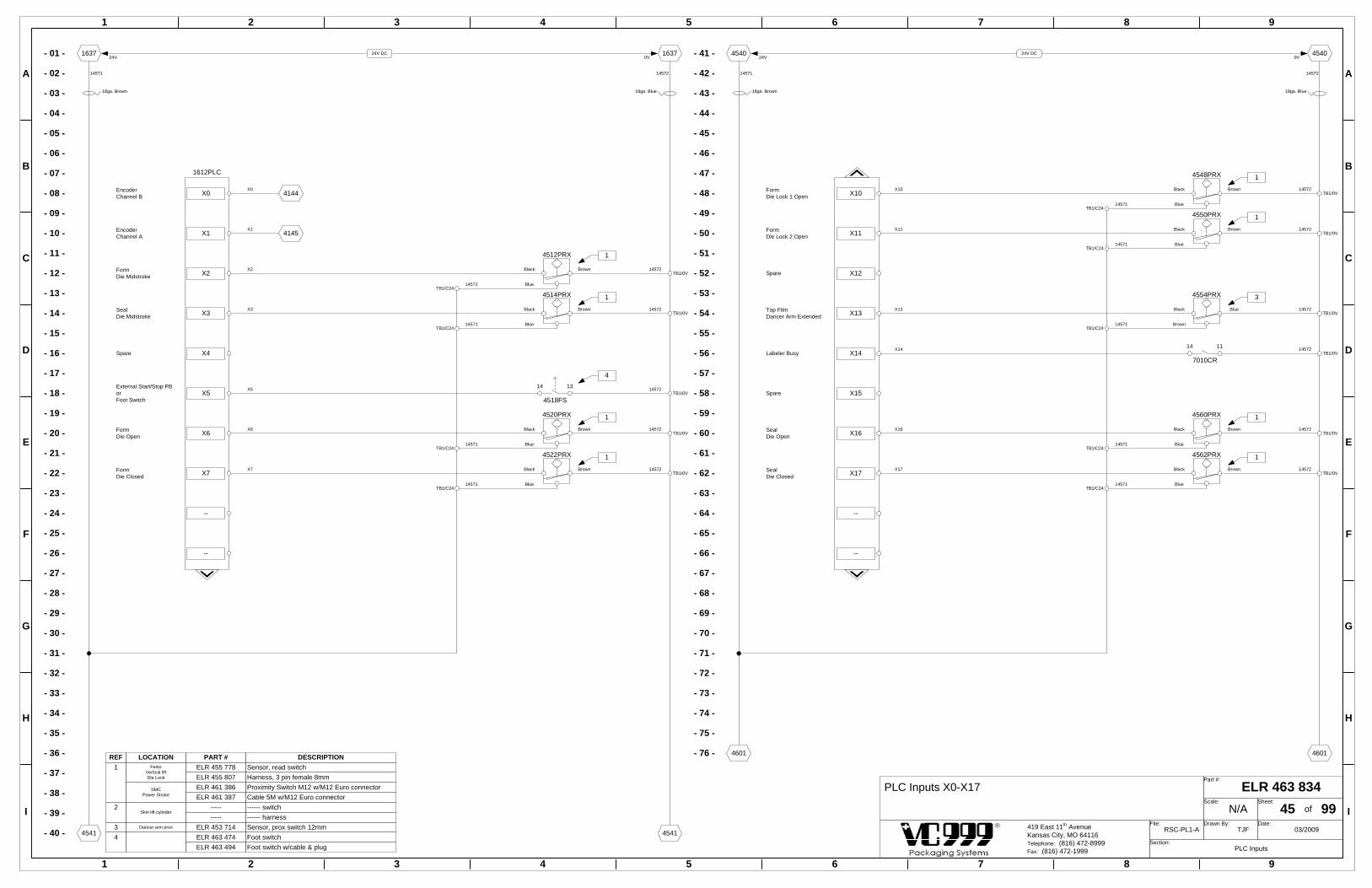
- 01 -
1 2 3 4 5 6 7 8 9
1 2 3 4 5 6 7 8 9
A
B
C
D
E
F
G
H
I
A
B
C
D
E
F
G
H
I
ELR 463 834Part #:
N/AScale:
45Sheet:
of 99RSC-PL1-A
File:TJF
Drawn By:03/2009
Date:
PLC InputsSection:
419 East 11th AvenueKansas City, MO 64116Telephone: (816) 472-8999Fax: (816) 472-1999
- 02 -
- 03 -
- 04 -
- 05 -
- 06 -
- 07 -
- 08 -
- 09 -
- 10 -
- 11 -
- 12 -
- 13 -
- 14 -
- 15 -
- 16 -
- 17 -
- 18 -
- 19 -
- 20 -
- 21 -
- 22 -
- 23 -
- 24 -
- 25 -
- 26 -
- 27 -
- 28 -
- 29 -
- 30 -
- 31 -
- 32 -
- 33 -
- 34 -
- 35 -
- 36 -
- 37 -
- 38 -
- 39 -
- 40 -
- 41 -
- 42 -
- 43 -
- 44 -
- 45 -
- 46 -
- 47 -
- 48 -
- 49 -
- 50 -
- 51 -
- 52 -
- 53 -
- 54 -
- 55 -
- 56 -
- 57 -
- 58 -
- 59 -
- 60 -
- 61 -
- 62 -
- 63 -
- 64 -
- 65 -
- 66 -
- 67 -
- 68 -
- 69 -
- 70 -
- 71 -
- 72 -
- 73 -
- 74 -
- 75 -
- 76 -
24V DC
14571 14572
18ga. Brown 18ga. Blue
1637 1637
45414541
24V DC
14571 14572
18ga. Brown 18ga. Blue
4540 4540
46014601
X0EncoderChannel B
X0
EncoderChannel A X1
FormDie Midstroke X2
SealDie Midstroke X3
Spare X4
External Start/Stop PBorFoot Switch
X5
FormDie Open X6
FormDie Closed X7
--
--
X1
X2
X3
X5
X6
X7
X10FormDie Lock 1 Open
X10
FormDie Lock 2 Open X11
Spare X12
Top FilmDancer Arm Extended X13
Labeler Busy X14
Spare X15
SealDie Open X16
SealDie Closed X17
--
--
X11
X13
X14
X16
X17
4144
4145
4512PRX
BrownBlack
Blue
4514PRX
BrownBlack
BlueTB1/C24
4520PRX
BrownBlack
Blue
4522PRX
BrownBlack
Blue
TB1/C24
TB1/C24
TB1/0V
TB1/0V
TB1/0V
TB1/0V
4554PRX
BlueBlack
BrownTB1/C24
4560PRX
BrownBlack
Blue
4562PRX
BrownBlack
Blue
TB1/C24
TB1/C24
TB1/0V
TB1/0V
TB1/0V
4550PRX
BrownBlack
Blue
TB1/0V
4548PRX
BrownBlack
Blue
TB1/0V
TB1/C24
TB1/C24
TB1/C2414571
14571
14571
14571
14571
14571
14571
14571
14571
14572
14572
14572
14572
14572
24V 0V 24V 0V
1
1
1
1
1
1
3
1
1
PART # DESCRIPTION
ELR 453 714 Sensor, prox switch 12mm3
14572
14572
14572
14572
PLC Inputs X0-X17
1612PLC
7010CR
14 11TB1/0V
14572
ELR 461 387 Cable 5M w/M12 Euro connectorELR 461 386 Proximity Switch M12 w/M12 Euro connector
Skin lift cylinder2
REF1
LOCATIONFesto
Vertical liftDle Lock
ELR 455 778 Sensor, read switchELR 455 807 Harness, 3 pin female 8mm
SMCPower Stroke
Dancer arm prox
----------
------ switch------ harness
TB1/0V14572
4518FS
1314
4
ELR 463 474ELR 463 494
Foot switchFoot switch w/cable & plug
4
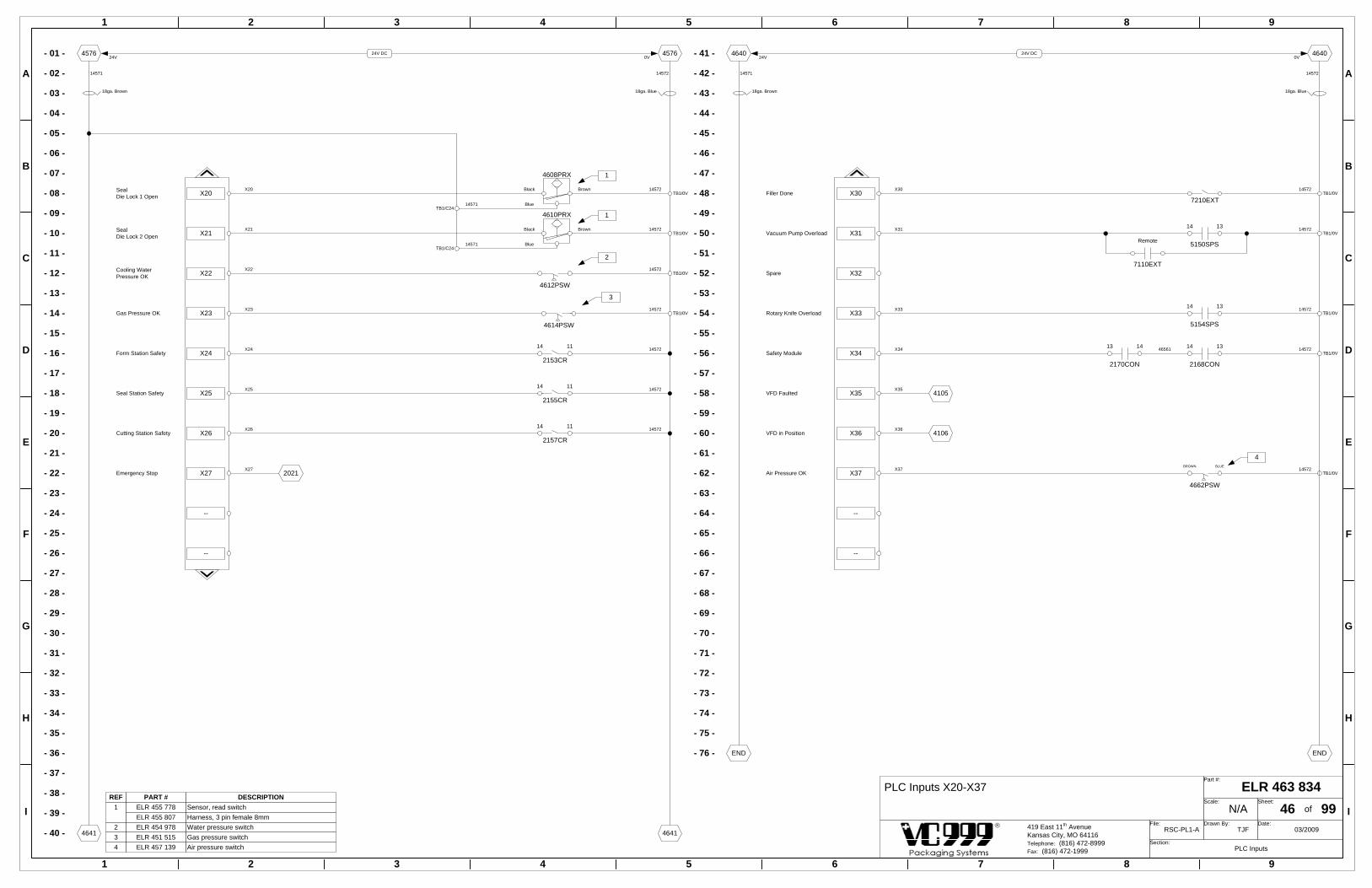
TB1/0V14572
- 01 -
1 2 3 4 5 6 7 8 9
1 2 3 4 5 6 7 8 9
A
B
C
D
E
F
G
H
I
A
B
C
D
E
F
G
H
I
PLC Inputs X20-X37 ELR 463 834Part #:
N/AScale:
46Sheet:
of 99RSC-PL1-A
File:TJF
Drawn By:03/2009
Date:
PLC InputsSection:
419 East 11th AvenueKansas City, MO 64116Telephone: (816) 472-8999Fax: (816) 472-1999
- 02 -
- 03 -
- 04 -
- 05 -
- 06 -
- 07 -
- 08 -
- 09 -
- 10 -
- 11 -
- 12 -
- 13 -
- 14 -
- 15 -
- 16 -
- 17 -
- 18 -
- 19 -
- 20 -
- 21 -
- 22 -
- 23 -
- 24 -
- 25 -
- 26 -
- 27 -
- 28 -
- 29 -
- 30 -
- 31 -
- 32 -
- 33 -
- 34 -
- 35 -
- 36 -
- 37 -
- 38 -
- 39 -
- 40 -
- 41 -
- 42 -
- 43 -
- 44 -
- 45 -
- 46 -
- 47 -
- 48 -
- 49 -
- 50 -
- 51 -
- 52 -
- 53 -
- 54 -
- 55 -
- 56 -
- 57 -
- 58 -
- 59 -
- 60 -
- 61 -
- 62 -
- 63 -
- 64 -
- 65 -
- 66 -
- 67 -
- 68 -
- 69 -
- 70 -
- 71 -
- 72 -
- 73 -
- 74 -
- 75 -
- 76 -
24V DC
14571 14572
18ga. Brown 18ga. Blue
4576 4576
46414641
24V DC
14571 14572
18ga. Brown 18ga. Blue
4640 4640
ENDEND
X20SealDie Lock 1 Open
X20
SealDie Lock 2 Open X21
Cooling WaterPressure OK X22
Gas Pressure OK X23
Form Station Safety X24
Seal Station Safety X25
Cutting Station Safety X26
Emergency Stop X27
--
--
X21
X22
X23
X24
X25
X26
X27
X30Filler DoneX30
Vacuum Pump Overload X31
Spare X32
Rotary Knife Overload X33
Safety Module X34
VFD Faulted X35
VFD in Position X36
Air Pressure OK X37
--
--
X31
X33
X34
X35
X36
X37
4610PRX
BrownBlack
Blue
TB1/0V
4608PRX
BrownBlack
Blue
TB1/0V
TB1/C24
TB1/C24
TB1/0V
TB1/0V
2153CR
14 11
2155CR
14 11
2157CR
14 11
4612PSW
4614PSW
4106
4105
5154SPS
1314TB1/0V
5150SPS
1314TB1/0V
2021
14571
14571
14572
14572
14572
14572
14572
14572
14572
14572
14572
24V 0V 24V 0V
PART # DESCRIPTIONREF1
ELR 455 807 Harness, 3 pin female 8mm2
ELR 457 139 Air pressure switch4
ELR 454 978 Water pressure switchGas pressure switchELR 451 5153
1
1
2
3
7110EXT
Remote
4
4662PSW
BLUEBROWN
2168CON
1314TB1/0V
14572
2170CON
1413 46561
7210EXTTB1/0V
14572
ELR 455 778 Sensor, read switch

- 01 -
1 2 3 4 5 6 7 8 9
1 2 3 4 5 6 7 8 9
A
B
C
D
E
F
G
H
I
A
B
C
D
E
F
G
H
I
PLC Outputs Y0-Y17 ELR 463 834Part #:
N/AScale:
50Sheet:
of 99RSC-PL1-A
File:TJF
Drawn By:03/2009
Date:
PLC OutputsSection:
419 East 11th AvenueKansas City, MO 64116Telephone: (816) 472-8999Fax: (816) 472-1999
- 02 -
- 03 -
- 04 -
- 05 -
- 06 -
- 07 -
- 08 -
- 09 -
- 10 -
- 11 -
- 12 -
- 13 -
- 14 -
- 15 -
- 16 -
- 17 -
- 18 -
- 19 -
- 20 -
- 21 -
- 22 -
- 23 -
- 24 -
- 25 -
- 26 -
- 27 -
- 28 -
- 29 -
- 30 -
- 31 -
- 32 -
- 33 -
- 34 -
- 35 -
- 36 -
- 37 -
- 38 -
- 39 -
- 40 -
- 41 -
- 42 -
- 43 -
- 44 -
- 45 -
- 46 -
- 47 -
- 48 -
- 49 -
- 50 -
- 51 -
- 52 -
- 53 -
- 54 -
- 55 -
- 56 -
- 57 -
- 58 -
- 59 -
- 60 -
- 61 -
- 62 -
- 63 -
- 64 -
- 65 -
- 66 -
- 67 -
- 68 -
- 69 -
- 70 -
- 71 -
- 72 -
- 73 -
- 74 -
- 75 -
- 76 -
24V DC
14671 14572
18ga. Brown 18ga. Blue
1712 1712
50415041
Y0 Formed Web BrakeY0
Index Pulse TrainY1
Cross Cut 1 orGuillotine supportY2
Cross Cut 2 orGuillotine cutY3
Top FilmDancer Arm ExtendY4
Top FilmSpindle BrakeY5
FormDie OpenY6
FormDie CloseY7
Output CommonCOM
--
Y1
Y2
Y3
Y4
Y5
Y6
Y7
24V DC
14671 14572
18ga. Brown 18ga. Blue
5040 5040
51015101
Y10 FormDie Lock
Y10
FormHeating VacuumY11
Chain LubricatorY12
FormForming Vacuum PilotY13
FormForming AirY14
Code DaterY15
SealDie OpenY16
SealDie CloseY17
Output CommonCOM
--
Y11
Y12
Y13
Y14
Y15
Y16
Y17
50701
5070FU
4119
5014SOL
5016SOL
5020SOL
5022SOL
5012SOL
5048SOL
5050SOL
5056SOL
5060SOL
5062SOL
24V 0V 24V 0V
14571
14671
14671
14671
14571
14671
14671 14671
14671
14671
14671
14671
2608Y0
2615
3008
1612PLC
14572
5054SOL
14671
5008SSR
5018SSR 5058SOL
14671
14671
5052SOL
1646
5045
14571
14571
5029
5105
14571
14571

- 01 -
1 2 3 4 5 6 7 8 9
1 2 3 4 5 6 7 8 9
A
B
C
D
E
F
G
H
I
A
B
C
D
E
F
G
H
I
PLC Outputs Y20-Y37 ELR 463 834Part #:
N/AScale:
51Sheet:
of 99RSC-PL1-A
File:TJF
Drawn By:03/2009
Date:
PLC OutputsSection:
419 East 11th AvenueKansas City, MO 64116Telephone: (816) 472-8999Fax: (816) 472-1999
- 02 -
- 03 -
- 04 -
- 05 -
- 06 -
- 07 -
- 08 -
- 09 -
- 10 -
- 11 -
- 12 -
- 13 -
- 14 -
- 15 -
- 16 -
- 17 -
- 18 -
- 19 -
- 20 -
- 21 -
- 22 -
- 23 -
- 24 -
- 25 -
- 26 -
- 27 -
- 28 -
- 29 -
- 30 -
- 31 -
- 32 -
- 33 -
- 34 -
- 35 -
- 36 -
- 37 -
- 38 -
- 39 -
- 40 -
- 41 -
- 42 -
- 43 -
- 44 -
- 45 -
- 46 -
- 47 -
- 48 -
- 49 -
- 50 -
- 51 -
- 52 -
- 53 -
- 54 -
- 55 -
- 56 -
- 57 -
- 58 -
- 59 -
- 60 -
- 61 -
- 62 -
- 63 -
- 64 -
- 65 -
- 66 -
- 67 -
- 68 -
- 69 -
- 70 -
- 71 -
- 72 -
- 73 -
- 74 -
- 75 -
- 76 -
24V DC
14671 14572
18ga. Brown 18ga. Blue
5076 5076
51415141
Y20 SealDie Lock
Y20
SealBalance VacuumY21
SealPackage VacuumY22
Gas FlushY23
Seal PlateY24
SealBalance VentY25
SealPackage VentY26
VFD EnableY27
Output CommonCOM
--
Y21
Y22
Y23
Y24
Y25
Y26
Y27
24V DC
14671 14572
18ga. Brown 18ga. Blue
5140 5140
52015201
Y30 Film Brake ResetY30
Vacuum Pump SPSORVacuum Pump Relay
Y31
Trim Removal - RevolvingY32
Rotary knife SPSY33
Safety Circuit ResetY34
VFD Fault ResetY35
Heater ControlY36
Main Air SupplyY37
Output CommonCOM
--
Y31
Y32
Y33
Y34
Y35
Y36
Y37
51701
5170FU
5108SOL
5110SOL
5112SOL
5114SOL
5116SOL
5118SOL
5120SOL
A2A1Vacuum pump SPS
5150SPS
A2A1
5154SPS
4118
TB1/S24
TB1/S24
A2A1
5160CR
A2A1
5156CR
24V 0V 24V 0V
TB1/S24A2A1
5152CR
Trim removal - revolving
14671
14671
14671
14671
14671
14671
14671
14671
14671
14671
A2A1
5151CR
Vacuum pump relay10504650
7106
1436
10454654
2058
20251657
14572
4124
5162SOL
14671TB1/S24
A2A1
5148CR
14671
5656
5069
5145
14571
14571
5129
5205
14571
14571
14571
14571

- 01 -
1 2 3 4 5 6 7 8 9
1 2 3 4 5 6 7 8 9
A
B
C
D
E
F
G
H
I
A
B
C
D
E
F
G
H
I
- 02 -
- 03 -
- 04 -
- 05 -
- 06 -
- 07 -
- 08 -
- 09 -
- 10 -
- 11 -
- 12 -
- 13 -
- 14 -
- 15 -
- 16 -
- 17 -
- 18 -
- 19 -
- 20 -
- 21 -
- 22 -
- 23 -
- 24 -
- 25 -
- 26 -
- 27 -
- 28 -
- 29 -
- 30 -
- 31 -
- 32 -
- 33 -
- 34 -
- 35 -
- 36 -
- 37 -
- 38 -
- 39 -
- 40 -
- 41 -
- 42 -
- 43 -
- 44 -
- 45 -
- 46 -
- 47 -
- 48 -
- 49 -
- 50 -
- 51 -
- 52 -
- 53 -
- 54 -
- 55 -
- 56 -
- 57 -
- 58 -
- 59 -
- 60 -
- 61 -
- 62 -
- 63 -
- 64 -
- 65 -
- 66 -
- 67 -
- 68 -
- 69 -
- 70 -
- 71 -
- 72 -
- 73 -
- 74 -
- 75 -
- 76 -
24V DC
14671 14572
18ga. Brown 18ga. Blue
5176 5176
52415241
Y40 Labeler StartY40
Filler StartY41
Cross Cut 3Y42
SpareY43
SpareY44
SpareY45
SpareY46
SpareY47
Output CommonCOM
--
Y41
Y42
24V DC
14671 14572
18ga. Brown 18ga. Blue
5240 5240
ENDEND
Y50 Spare
SpareY51
SpareY52
SpareY53
SpareY54
SpareY55
SpareY56
SpareY57
Output CommonCOM
--
52701
PLC Outputs Y40-Y57 ELR 463 834Part #:
N/AScale:
52Sheet:
of 99RSC-PL1-A
File:TJF
Drawn By:03/2009
Date:
PLC OutputsSection:
419 East 11th AvenueKansas City, MO 64116Telephone: (816) 472-8999Fax: (816) 472-1999
5270FU
24V 0V 24V 0V
5207PLC
14572
A2A1
5208CR
14671
7006
A2A1
5210CR
14671
7206
5212SOL
14671
5169
5245
14571
14571
5229
END
14571
14571
Not Installed

- 01 -
1 2 3 4 5 6 7 8 9
1 2 3 4 5 6 7 8 9
A
B
C
D
E
F
G
H
I
A
B
C
D
E
F
G
H
I
- 02 -
- 03 -
- 04 -
- 05 -
- 06 -
- 07 -
- 08 -
- 09 -
- 10 -
- 11 -
- 12 -
- 13 -
- 14 -
- 15 -
- 16 -
- 17 -
- 18 -
- 19 -
- 20 -
- 21 -
- 22 -
- 23 -
- 24 -
- 25 -
- 26 -
- 27 -
- 28 -
- 29 -
- 30 -
- 31 -
- 32 -
- 33 -
- 34 -
- 35 -
- 36 -
- 37 -
- 38 -
- 39 -
- 40 -
- 41 -
- 42 -
- 43 -
- 44 -
- 45 -
- 46 -
- 47 -
- 48 -
- 49 -
- 50 -
- 51 -
- 52 -
- 53 -
- 54 -
- 55 -
- 56 -
- 57 -
- 58 -
- 59 -
- 60 -
- 61 -
- 62 -
- 63 -
- 64 -
- 65 -
- 66 -
- 67 -
- 68 -
- 69 -
- 70 -
- 71 -
- 72 -
- 73 -
- 74 -
- 75 -
- 76 -
24V DC
14571 14572
18ga. Brown 18ga. Blue
1650 1650
55415541
24V DC
14571 14572
18ga. Brown 18ga. Blue
5540 5540
ENDEND
CT
CT
PTA
ShieldFG
Channel 2Thermocouple (+)TC+
Channel 2Thermocouple (-)TC-
55561
55581
24+14571
24-
GROUND
Channel 1OutputOUT 1
OutputCommonCOM
Channel 2OutputOUT 2
CT
CT
PTA
ShieldFG
14572
55141
14572
55181
Channel 1Thermocouple (+)TC+
55281
Channel 1Thermocouple (-)TC-
55301
Temperature Controller 1 (Heat Zones 1 & 2)FX2N-2LC
ELR 463 834Part #:
N/AScale:
55Sheet:
of 99RSC-PL1-A
File:TJF
Drawn By:03/2009
Date:
PLC ModulesSection:
419 East 11th AvenueKansas City, MO 64116Telephone: (816) 472-8999Fax: (816) 472-1999
TB1/C24
TB1/0V
TB1/C24
5529TC
5557TC
Heat Zone 1 (Seal)Thermocouple
Heat Zone 2 (Form)Thermocouple
24V 0V 24V 0V
14571
14571
14572
1244
1252
5507PLC
Heat Zone 1 (Seal)
5514SSR
Heat Zone 2 (Form)
5518SSR

- 01 -
1 2 3 4 5 6 7 8 9
1 2 3 4 5 6 7 8 9
A
B
C
D
E
F
G
H
I
A
B
C
D
E
F
G
H
I
Top Film RegistrationFX2N-1HC
ELR 463 834Part #:
N/AScale:
56Sheet:
of 99RSC-PL1-A
File:TJF
Drawn By:03/2009
Date:
PLC ModulesSection:
419 East 11th AvenueKansas City, MO 64116Telephone: (816) 472-8999Fax: (816) 472-1999
- 02 -
- 03 -
- 04 -
- 05 -
- 06 -
- 07 -
- 08 -
- 09 -
- 10 -
- 11 -
- 12 -
- 13 -
- 14 -
- 15 -
- 16 -
- 17 -
- 18 -
- 19 -
- 20 -
- 21 -
- 22 -
- 23 -
- 24 -
- 25 -
- 26 -
- 27 -
- 28 -
- 29 -
- 30 -
- 31 -
- 32 -
- 33 -
- 34 -
- 35 -
- 36 -
- 37 -
- 38 -
- 39 -
- 40 -
- 41 -
- 42 -
- 43 -
- 44 -
- 45 -
- 46 -
- 47 -
- 48 -
- 49 -
- 50 -
- 51 -
- 52 -
- 53 -
- 54 -
- 55 -
- 56 -
- 57 -
- 58 -
- 59 -
- 60 -
- 61 -
- 62 -
- 63 -
- 64 -
- 65 -
- 66 -
- 67 -
- 68 -
- 69 -
- 70 -
- 71 -
- 72 -
- 73 -
- 74 -
- 75 -
- 76 -
24V DC
14571 14572
18ga. Brown 18ga. Blue
1651 1651
56415641
24V DC
14571 14572
18ga. Brown 18ga. Blue
5640 5640
ENDEND
TB1/C24
4151
A12+ Encoder CommonChannel A 12V
Encoder CommonChannel A 24VA24+
Encoder Channel AA-
Encoder CommonChannel A 5VA5+
Encoder CommonChannel B 12VB12+
Encoder CommonChannel B 24VB24+
Encoder Channel BB-
Encoder CommonChannel B 5VB5+
Disable Input 5VXD5
Disable Input 12-24VXD24
14571
56201
Disable Input CommonCOMD
COMP Preset Input Common
Preset input 5VXP5
Hardware OutputNegativeYH-
Hardware OutputPositiveYH+
Software OutputNegativeYS-
Software OutputPositiveYS+
56541
56562
Preset Input 12-24VXP24
5654PES
TB1/C24
A2A1
5656CR
Top Film Brake
5148CR
11 12
5656CR
14 11TB1/0V
5656CR
24 21Top Film Brake
5668SOL
TB1/0V
TB1/C24
Top Film Brake
Top Film Brake
Film Brake Reset
24V 0V 24V 0V
1
PART # DESCRIPTIONREF
ELR 450 999 7 pin plug, male1
ELR 458 457 Assembly - slot sensor with plug
ELR 450 999 7 pin plug, male
1ELR 456 615 5 pin, harness with 12mm connector
ELR 456 614 Slot sensor photo eye (banner)
ELR 452 099 Photo eye (balluff)
14572
14572
14572
14571
14571
14571
56561 56562
56562
14571
56645668
5607PLC
Not Installed
56681
TB1/0V14572

- 01 -
1 2 3 4 5 6 7 8 9
1 2 3 4 5 6 7 8 9
A
B
C
D
E
F
G
H
I
A
B
C
D
E
F
G
H
I
- 02 -
- 03 -
- 04 -
- 05 -
- 06 -
- 07 -
- 08 -
- 09 -
- 10 -
- 11 -
- 12 -
- 13 -
- 14 -
- 15 -
- 16 -
- 17 -
- 18 -
- 19 -
- 20 -
- 21 -
- 22 -
- 23 -
- 24 -
- 25 -
- 26 -
- 27 -
- 28 -
- 29 -
- 30 -
- 31 -
- 32 -
- 33 -
- 34 -
- 35 -
- 36 -
- 37 -
- 38 -
- 39 -
- 40 -
- 41 -
- 42 -
- 43 -
- 44 -
- 45 -
- 46 -
- 47 -
- 48 -
- 49 -
- 50 -
- 51 -
- 52 -
- 53 -
- 54 -
- 55 -
- 56 -
- 57 -
- 58 -
- 59 -
- 60 -
- 61 -
- 62 -
- 63 -
- 64 -
- 65 -
- 66 -
- 67 -
- 68 -
- 69 -
- 70 -
- 71 -
- 72 -
- 73 -
- 74 -
- 75 -
- 76 -
24V DC
14571 14572
18ga. Brown 18ga. Blue
1652 1652
57415741
24V DC
14571 14572
18ga. Brown 18ga. Blue
5740 5740
ENDEND
Vacuum Sensor (4 Channel Analog Block)FX3U-4AD-ADP
ELR 463 834Part #:
N/AScale:
57Sheet:
of 99RSC-PL1-A
File:TJF
Drawn By:03/2009
Date:
PLC ModulesSection:
419 East 11th AvenueKansas City, MO 64116Telephone: (816) 472-8999Fax: (816) 472-1999
+/- 1.2 Bar4-20mA
Vacuum Sensor
1 4Brown Black
TB1/C24
Package Vacuum
24V 0V 24V 0V
1
PART # DESCRIPTIONREF1
14571
14571
14572
ELR 456 615 Harness 5 pin female 12mm connectorELR 462 149 Vacuum sensor with hose connection
5720PSA
24+14571
24-
GROUND
Voltage Input 1V1+
Amperage Input 1I1+
Common Input 1COM1
Voltage Input 2V2+
Amperage Input 2I2+
Common Input 2COM2
14572
57201
57201
14572
5707PLC
Voltage Input 3V3+
Amperage Input 3I3+
Common Input 3COM3
Voltage Input 4V4+
Amperage Input 4I4+
Common Input 4COM4
Not Installed

1 2 3 4 5 6 7 8 9
1 2 3 4 5 6 7 8 9
A
B
C
D
E
F
G
H
I
A
B
C
D
E
F
G
H
I
Die Plug ELR 463 834Part #:
N/AScale:
60Sheet:
of 99RSC-PL1-A
File:TJF
Drawn By:03/2009
Date:
PlugsSection:
419 East 11th AvenueKansas City, MO 64116Telephone: (816) 472-8999Fax: (816) 472-1999
GREENBLACKWHITE
RED--
ORANGE--
DESCRIPTIONGROUNDThermocoupleThermocoupleHeaters--Heaters--
PIN SIZE
Type B-4.00
Type B-4.00
--
--Type B-4.00
PIN
123456
WIRE COLOR (DIE)GREENBLUE
BROWNRED
--YELLOW
--
WIRE COLOR (CABLE)
--
Type B-4.00Type B-4.00
PART # DESCRIPTION
ELR 451 968 Plug M3, receptacle with threads
REFELR 452 308 Assembly, plug with wires1
ELR 451 969ELR 455 530
Plug M3, pin insert 7 pinPin contact, type B 4.00
ELR 458 764 14 ga. THHN blue wire, 390mmELR 458 765ELR 458 766ELR 458 767ELR 460 845
14 ga. THHN red wire, 390mm14 ga. THHN yellow wire, 390mm14 ga. THHN brown wire, 390mm12 ga. THHN green wire, 390mm
ELR 455 529ELR 451 970ELR 455 531ELR 451 967
Plug M3, cable sleevePlug M3, socket insert 7 pinSocket contact, type B 4.00Plug M3, receptacle with strain relief
2
ELR 451 974 Extraction tool for type B contacts
Die Machine
Die Plug
KEYKEY
21

1 2 3 4 5 6 7 8 9
1 2 3 4 5 6 7 8 9
A
B
C
D
E
F
G
H
I
A
B
C
D
E
F
G
H
I
Column ConnectionsRight Column - Top
ELR 463 834Part #:
N/AScale:
61Sheet:
of 99RSC-PL1-A
File:TJF
Drawn By:03/2009
Date:
PlugsSection:
419 East 11th AvenueKansas City, MO 64116Telephone: (816) 472-8999Fax: (816) 472-1999
PART # DESCRIPTIONELR 452 310 Assembly, 7 pin plug with 4500mm cable
REF
ELR 451 000 7 pin plug, male1
ELR 450 999 7 pin plug, female2
PHOTO-EYE(film registration)
NOT USEDBANNER
SLOT SENSOR PHOTO-EYE
BALLUFFPHOTO-EYE
BLACK
BROWN
GREY
BLUE
WHITE
BLACK
BROWN
GREY
BLUE
WHITE
PHOTO-EYE (film registration)
ELR 456 614 Photo-eye slot sensor3 ELR 458 457 Assembly, Photo-eye slot sensor with plug
ELR 452 099 Photo-eye (balluff)4ELR 455 765 Harness 5 pin female 12mm connector5
Red switch inside eye must be set to sinking output
RED SWITCH
Right, top column
1
3 4
5
Front Side
12
345
67
Front Side
12
3
65
47
WhiteBlue
--Brown
------
DESCRIPTIONSignal0 VDC--24 VDC----
PIN123456
ReceptacleWhiteBlack
--Red
----
Banner Photo-Eye
--7--
WhiteBlue
--Brown
------
Balluff Photo-Eye5654PES
5654PES
2
NOT USED

1 2 3 4 5 6 7 8 9
1 2 3 4 5 6 7 8 9
A
B
C
D
E
F
G
H
I
A
B
C
D
E
F
G
H
I
Column ConnectionsLeft Column - Middle
ELR 463 834Part #:
N/AScale:
62Sheet:
of 99RSC-PL1-A
File:TJF
Drawn By:03/2009
Date:
PlugsSection:
419 East 11th AvenueKansas City, MO 64116Telephone: (816) 472-8999Fax: (816) 472-1999
Foot switch
Left, middle column
Not used
-- ELR 462 177 Extraction tool for type A contacts
GREEN----312
DESCRIPTIONGROUND----Not used0V DCSignal
PIN SIZE
--Type A-1.50
--
PIN
12345
WIRE # (receptacle)GREEN
----312
WIRE # (plug)
Machine Foot Switch
Foot Switch
PLUG KEY
21
PLUG KEY
M1 - KEY 1 M1 - KEY 1
Type A-1.50Type A-1.50
PART # DESCRIPTIONREFELR 463 489 Assembly, plug M1-Key 1 w/3100mm cable 1ELR 460 228 Plug M1, receptacle with flangeELR 460 223 Plug M1, capELR 460 229 Plug M1, socket insertELR 460 230 Socket contact, type A 1.50ELR 458 582 Cable, 4 conductor 16 AWG
ELR 458 582 Cable, 4 conductor 16 AWG
ELR 460 222 Plug M1, plug with strain reliefELR 460 225 Plug M1, cable sleeveELR 460 224 Plug M1, pin insert
2
ELR 460 226 Pin contact, type A 1.50
ELR 463 490 Assembly, plug M1-Key 1 w/6000mm cable
Type A-1.50

1 2 3 4 5 6 7 8 9
1 2 3 4 5 6 7 8 9
A
B
C
D
E
F
G
H
I
A
B
C
D
E
F
G
H
I
Air Manifold Layout & Wiring Harness ELR 463 834Part #:
N/AScale:
65Sheet:
of 99RSC-PL1-A
File:TJF
Drawn By:03/2009
Date:
PneumaticsSection:
419 East 11th AvenueKansas City, MO 64116Telephone: (816) 472-8999Fax: (816) 472-1999
1
DOTCOLOR
STATION#
2
3
4
567
SEAL STATION
A
WIRECOLOR
BABABAB
GRAYWHITEWHITE
N/AN/AN/AN/AN/AN/AN/A
WHITEBLACKBLACK
RED
DOUBLE
BASESOLENOIDS
DOUBLE
DOUBLE
DOUBLE
SINGLESINGLESINGLE
BLACKBROWN
REDORANGEYELLOW
PINKBLUE
PURPLEAAA
COIL
8910
YELLOWORANGEYELLOW
REDRED
BLACK
SINGLESINGLESINGLE
AAA
111213
PINKBLUE
PURPLE
BLACKWHITE
N/A
SINGLESINGLESINGLE
AAA
141516
GRAYORANGE
RED
N/ABLACKWHITE
SINGLESINGLESINGLE
AAA
171819
BROWNPINKGRAY
WHITEREDRED
SINGLESINGLESINGLE
AAA
2024VDC COMMON
BLACKWHITE
WHITEN/A
SINGLE A
1
DOTCOLOR
STATION#
2
3
4
5
6
FORM STATION
A
WIRECOLOR
BABABAB
GRAYWHITEWHITE
N/AN/AN/AN/AN/AN/AN/A
WHITEBLACKBLACK
RED
DOUBLE
BASESOLENOIDS
DOUBLE
DOUBLE
DOUBLE
DOUBLE
DOUBLE
BLACKBROWN
REDORANGEYELLOW
PINKBLUE
PURPLEABA
COIL
7
YELLOWORANGEYELLOW
REDRED
BLACKDOUBLE
BAB
8
9
PINKBLUE
PURPLE
BLACKWHITE
N/A
DOUBLE
DOUBLE
ABA
10
GRAYORANGE
RED
N/ABLACKWHITE
DOUBLE
BAB
11
12
BROWNPINKGRAY
WHITEREDRED
DOUBLE
DOUBLE
ABA
24VDC COMMONBLACKWHITE
WHITEN/A
B
1234567891011121314151617181920STATION #
DOUBLE SOLENOID
WIRING HARNESS
SINGLE SOLENOID
Air manifold wiring is determined by the base. The base is either a single or double solenoid base. The single solenoid base
controls 1 single solenoid valve. A double solenoid base can control either a single of double solenoid valve but always
requires the wires for a double solenoid valve.
To determine valve wiring find the station # of the valve (position from harness side of manifold)
and refer to the chart below.

- 01 -
1 2 3 4 5 6 7 8 9
1 2 3 4 5 6 7 8 9
A
B
C
D
E
F
G
H
I
A
B
C
D
E
F
G
H
I
Interface Summary - Labeler ELR 463 834Part #:
N/AScale:
70Sheet:
of 99RSC-PL1-A
File:TJF
Drawn By:03/2009
Date:
Interface SummarySection:
419 East 11th AvenueKansas City, MO 64116Telephone: (816) 472-8999Fax: (816) 472-1999
- 02 -
- 03 -
- 04 -
- 05 -
- 06 -
- 07 -
- 08 -
- 09 -
- 10 -
- 11 -
- 12 -
- 13 -
- 14 -
- 15 -
- 16 -
- 17 -
- 18 -
- 19 -
- 20 -
- 21 -
- 22 -
- 23 -
- 24 -
- 25 -
- 26 -
- 27 -
- 28 -
- 29 -
- 30 -
- 31 -
- 32 -
- 33 -
- 34 -
- 35 -
- 36 -
- 37 -
- 38 -
- 39 -
- 40 -
- 41 -
- 42 -
- 43 -
- 44 -
- 45 -
- 46 -
- 47 -
- 48 -
- 49 -
- 50 -
- 51 -
- 52 -
- 53 -
- 54 -
- 55 -
- 56 -
- 57 -
- 58 -
- 59 -
- 60 -
- 61 -
- 62 -
- 63 -
- 64 -
- 65 -
- 66 -
- 67 -
- 68 -
- 69 -
- 70 -
- 71 -
- 72 -
- 73 -
- 74 -
- 75 -
- 76 -
Labeler 1MACHINE
7010CR
14 11
Labeler Start
Labeler Busy 7010CRTB1/0V
PLC Input X14X14
14572
A2 A1
5208CRTB1/S24
PLC Output Y40
14671
Y40
5208CR
1411
12

- 01 -
1 2 3 4 5 6 7 8 9
1 2 3 4 5 6 7 8 9
A
B
C
D
E
F
G
H
I
A
B
C
D
E
F
G
H
I
Interface Summary - Remote Vacuum Pump Control ELR 463 834Part #:
N/AScale:
71Sheet:
of 99RSC-PL1-A
File:TJF
Drawn By:03/2009
Date:
Interface SummarySection:
419 East 11th AvenueKansas City, MO 64116Telephone: (816) 472-8999Fax: (816) 472-1999
- 02 -
- 03 -
- 04 -
- 05 -
- 06 -
- 07 -
- 08 -
- 09 -
- 10 -
- 11 -
- 12 -
- 13 -
- 14 -
- 15 -
- 16 -
- 17 -
- 18 -
- 19 -
- 20 -
- 21 -
- 22 -
- 23 -
- 24 -
- 25 -
- 26 -
- 27 -
- 28 -
- 29 -
- 30 -
- 31 -
- 32 -
- 33 -
- 34 -
- 35 -
- 36 -
- 37 -
- 38 -
- 39 -
- 40 -
- 41 -
- 42 -
- 43 -
- 44 -
- 45 -
- 46 -
- 47 -
- 48 -
- 49 -
- 50 -
- 51 -
- 52 -
- 53 -
- 54 -
- 55 -
- 56 -
- 57 -
- 58 -
- 59 -
- 60 -
- 61 -
- 62 -
- 63 -
- 64 -
- 65 -
- 66 -
- 67 -
- 68 -
- 69 -
- 70 -
- 71 -
- 72 -
- 73 -
- 74 -
- 75 -
- 76 -
Vacuum Pump ControlMACHINE
7110EXT
Vacuum PumpRun
Vacuum PumpOverload 7110EXT
TB1/0V
PLC Input X31X31
14572
Vacuum Pump Run
Vacuum Pump Run
Vacuum Pump Overload
Vacuum Pump Overload
Vacuum Pump Run
Vacuum Pump Run
Vacuum Pump Overload
Vacuum Pump Overload
Remote Vacuum Pump Control Harness
A2 A1
5151CRTB1/S24
PLC Output Y31
14671
Y31
5151CR
1411

- 01 -
1 2 3 4 5 6 7 8 9
1 2 3 4 5 6 7 8 9
A
B
C
D
E
F
G
H
I
A
B
C
D
E
F
G
H
I
Interface Summary - Filler ELR 463 834Part #:
N/AScale:
72Sheet:
of 99RSC-PL1-A
File:TJF
Drawn By:03/2009
Date:
Interface SummarySection:
419 East 11th AvenueKansas City, MO 64116Telephone: (816) 472-8999Fax: (816) 472-1999
- 02 -
- 03 -
- 04 -
- 05 -
- 06 -
- 07 -
- 08 -
- 09 -
- 10 -
- 11 -
- 12 -
- 13 -
- 14 -
- 15 -
- 16 -
- 17 -
- 18 -
- 19 -
- 20 -
- 21 -
- 22 -
- 23 -
- 24 -
- 25 -
- 26 -
- 27 -
- 28 -
- 29 -
- 30 -
- 31 -
- 32 -
- 33 -
- 34 -
- 35 -
- 36 -
- 37 -
- 38 -
- 39 -
- 40 -
- 41 -
- 42 -
- 43 -
- 44 -
- 45 -
- 46 -
- 47 -
- 48 -
- 49 -
- 50 -
- 51 -
- 52 -
- 53 -
- 54 -
- 55 -
- 56 -
- 57 -
- 58 -
- 59 -
- 60 -
- 61 -
- 62 -
- 63 -
- 64 -
- 65 -
- 66 -
- 67 -
- 68 -
- 69 -
- 70 -
- 71 -
- 72 -
- 73 -
- 74 -
- 75 -
- 76 -
FILLERMACHINE
7210EXT
Filler Start
Filler Done 7210EXT
A2 A1
5210CR
TB1/0V
TB1/S24
PLC Output Y41
PLC Input X30X30
14572
14671
Y41
Filler Start
Filler Start
Filler Done
Filler Done
Filler Start
Filler Start
Filler Done
Filler Done
Filler Harness
5210CR
1411
12

SECTION 9 - PARTS LIST / ASSEMBLY DRAWINGS

1
B. Borchardt-
Packaging Systems
R
Telephone 816-472-8999 Fax 816-472-1999419 East 11th Avenue Kansas City, MO 64116
Drawn by
Date
Checked by
Scale
Part No.
1:10FUG 464396
assm, flm dul 420 F
Drawing File 464396 ofSheet1
7-9-09
2
1
REVISIONS
REV. DESCRIPTION DATE APPROVED
1 Added Cap 11/5/2009 BEB
2 Added thrust brng 5/17/2010 ADB
33
16
29
22
18
1725
11
9
17
13
12
1915
10
21
20
5
6
4
1
3
87
2
30
28
27
17
14
32
26
34
35
ITEM NO. QTY. DEPARTMENT PART NO. DESCRIPTION1 1 RSA R63893 right side top web2 1 FUG 462489 assm, flm unwnd 420 F3 1 RSA R63892 nutplate4 4 FSC 450978 M5x10 FHSCS5 1 RSA R63889 plate, form film doul6 1 RSA r60178 column attachment bar7 1 STL R63969 brake cover8 4 FSC 450949 screw, M6x60 SHCS9 1 RSA R65985 shaft, take up mnt w/ zerk h
10 1 RSA R61947 ring, spacr 25x33x5.511 1 RSA R63887 arm, dancer12 1 FBR 453470 Bearing, 25x52m BALL13 1 FBR 454965 Bearing, 25x52m BALL14 1 RSA R65984 support, spring w/ zerk hole15 1 FSC 451591 screw, M12x120 SHCS16 1 FSC 460212 spring, torsion17 4 FBR 450893 bearing, 20x47mm ball18 2 RSA R61889 rolr, tensn arm 42019 1 FSC 450901 screw, M12x20 SHCS20 1 RSA R63890 holder, sensor21 2 FSC 451023 M4x20 SHCS22 1 ELR 453714 sensor, prox DC M1223 1 ELR 453147 strn rlf, M16x7mm24 4 FSC 457671 screw, M8x35 SHCS25 2 RSA R64429 420, up unwind roller26 2 FSC 457670 screw, M10x40 SHCS27 2 FUG R60072 film roll set collar28 1 RSA R64426 brkt, up unwnd conct29 2 FSC 453492 screw, M10x30 HHCS30 2 FSC 451034 M10 flat washer31 2 RSA R60072 film roller set collar32 1 FSC 450810 pin, dowel 4x20mm33 1 FSC 458216 fit, grease 6mm34 1 RSA R64560 cap, frnt unwnd35 1 RSA R62600 brg, 35mm THRST
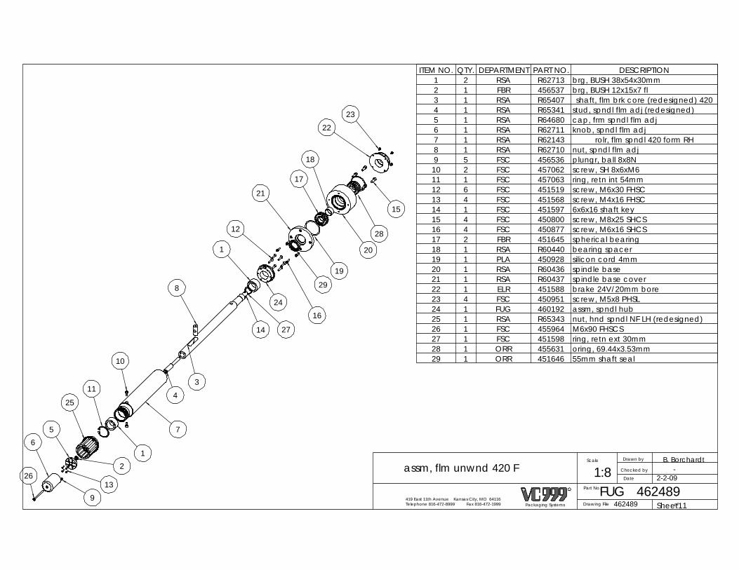
-
Packaging Systems
R
Telephone 816-472-8999 Fax 816-472-1999419 East 11th Avenue Kansas City, MO 64116
Drawn by
Date
Checked by
Scale B. Borchardt
Part No.
1:8FUG
assm, flm unwnd 420 F
462489462489Drawing File ofSheet11
2-2-09
19
8
14 27
1
24
12
16
21
17
18
20
23
15
29
34
10
1
11
25
2
139
26
65 7
22
28
ITEM NO. QTY. DEPARTMENT PART NO. DESCRIPTION1 2 RSA R62713 brg, BUSH 38x54x30mm2 1 FBR 456537 brg, BUSH 12x15x7 fl3 1 RSA R65407 shaft, flm brk core (redesigned) 4204 1 RSA R65341 stud, spndl flm adj (redesigned)5 1 RSA R64680 cap, frm spndl flm adj6 1 RSA R62711 knob, spndl flm adj7 1 RSA R62143 rolr, flm spndl 420 form RH8 1 RSA R62710 nut, spndl flm adj9 5 FSC 456536 plungr, ball 8x8N10 2 FSC 457062 screw, SH 8x6xM611 1 FSC 457063 ring, retn int 54mm12 6 FSC 451519 screw, M6x30 FHSC13 4 FSC 451568 screw, M4x16 FHSC14 1 FSC 451597 6x6x16 shaft key15 4 FSC 450800 screw, M8x25 SHCS16 4 FSC 450877 screw, M6x16 SHCS17 2 FBR 451645 spherical bearing18 1 RSA R60440 bearing spacer19 1 PLA 450928 silicon cord 4mm20 1 RSA R60436 spindle base21 1 RSA R60437 spindle base cover22 1 ELR 451588 brake 24V/20mm bore23 4 FSC 450951 screw, M5x8 PHSL24 1 FUG 460192 assm, spndl hub25 1 RSA R65343 nut, hnd spndl NF LH (redesigned)26 1 FSC 455964 M6x90 FHSCS27 1 FSC 451598 ring, retn ext 30mm28 1 ORR 455631 oring, 69.44x3.53mm29 1 ORR 451646 55mm shaft seal

Sheet1Packaging Systems
R
Telephone 816-472-8999 Fax 816-472-1999419 East 11th Avenue Kansas City, MO 64116
Drawn by
Date
Revisions:
Checked by
Scale S. WILLCOTT
1:1
of
Part No. FUG
assm, spndl hub
460192460192Drawing File 1
1
2
ITEM NO. QTY. DEPARTMENT PART NO. DESCRIPTION1 1 RSA R63794 hub,spndl2 3 FSC 450900 M6x10 FHSCS

REVISIONS
REV. DESCRIPTION DATE APPROVED
1 Updated safety switch & end cap 4/2/2009 BEB
2 Added ALU 464736 mac valve cover 11/18/2009 BEB
3 Removed MAC valve replaced with Festo and manifold 12/16/2009 ADB
Part No.
1:18STL 463735
assm, form st 420 up unwind Kchain
Drawing File 463735 ofSheet1 2
B. BorchardtBEB
Packaging Systems
R
Telephone 816-472-8999 Fax 816-472-1999419 East 11th Avenue Kansas City, MO 64116
Drawn by
Date
Checked by
Scale
3-3-09
24
5
25
31
12
40
39
41
44
46 4732
2111
12
9
32
14
6
30
15
2738
33
7
18
4
29
17
1
37
20
10
19
28
?
34
23
835
22
13
45
3

3
Sheet22
B. BorchardtBEB
Packaging Systems
R
Telephone 816-472-8999 Fax 816-472-1999419 East 11th Avenue Kansas City, MO 64116
Drawn by
Date
Checked by
Scale
Part No.
1:10STL 463735
assm, form st 420 up unwind Kchain
Drawing File 463735 of
3-3-09
3
ITEM NO. QTY. DEPARTMENT PART NO. DESCRIPTION1 1 STL 457847 assm, main frm F 4202 2 RSA R62383 blk, chin gd mnt frm 3 4 RSA R62381 blk, chin gd mnt rtn4 2 RSA R62380 blk, chin gd mnt frm 5 1 RSA R62382 blk, utility frm OP6 1 STL 458253 assm, utility F blk UT7 2 RSA R62388 slide, FS utility mnt8 1 RSA R62390 panel, pneumtic SMC9 2 DLM 463037 assm, die lift cyl V - improved
10 2 DLM 456151 assm, die lift link11 2 RSA R62394 shaft, die lft gr 42012 4 RSA R65204 assm, K-chain guide form st.13 1 RSA R60005 att.block kneefree L14 1 RSA R60068 att.block knee free15 2 RSA R60227 f safety sensor mnt16 4 ELR 463908 assm, switch safety17 1 ALU 461878 end cap infeed F 420 no cuts18 1 ALU R60183 UT sprocket cover19 1 ALU R60180 OP sprocket cover20 2 FTR 462636 assm, 5/8" k-chain opener sprocket21 1 FUG R65747 assm., main F infeed roller 42022 1 PRS 454978 assm, sensor water pressure23 3 ELR 455778 sensor, rd switch 24 4 RSA R60204 sub panel spacers25 4 FSC 455572 nut, 1/2-20 hex thin26 22 FSC 450806 screw, M6x12 SHCS27 10 FSC 451649 M8x25 FHSCS28 6 FSC 451595 screw, M5x16 SHCS29 4 FSC 450801 M6x30 SHCS30 16 FSC 451634 M8x80 SHCS31 4 FSC 451414 M8x60 SHCS32 4 FSC 451629 screw, M6x12 HHCS33 2 FSC 457533 screw, M12x140 SHCS34 4 FSC 450812 pin, dowel 6x40mm 35 4 FSC 450804 screw, M8x30 SHCS
ITEM NO. QTY. DEPARTMENT PART NO. DESCRIPTION36 1 RSA R63893 right side top web37 2 RSA R65269 bushing, form roller38 2 RSA R65268 standoff, open sprkt - 5/8 chain39 1 FUG 463744 assm,flm rlr 42040 1 ALU 458821 end cap form/seal 420 dp41 1 PRS 456200 assm, valv soln 5/3v42 1 PRS 458493 filtr, miro mist 43 1 PRS 458315 assm, air reg ST44 1 PRS 464946 assm, die lift cyl manifold, seal45 2 PRS 464948 fitting, 1/2 blk hd, 7/8-1446 2 FSC 461411 Hex Head CS M8 - 1.25 x 4047 2 FSC 450848 washer M8 flat

Sheet1 1Packaging Systems
R
Telephone 816-472-8999 Fax 816-472-1999419 East 11th Avenue Kansas City, MO 64116
Drawn by
Date
Checked by
Scale B. SARSFIELD
Part No.
1:12STL 457847
assm, main frm F 420
Drawing File 457847 of
10/8/08
REVISIONS
REV. DESCRIPTION DATE APPROVED
1 Turned over foot mounting block 5/18/2009 BEB
7
2
4
3
1
10
9
8
116
5
ITEM NO. QTY. DEPARTMENT PART NO. DESCRIPTION1 2 RSA R60087 upper cross member 4202 1 RSA R62355 frm, form side OP3 1 RSA R62356 frm, form side UT-imprvd4 1 ALU 456507 WRAP, FORM UTILITY5 1 STL R60023 form cabinet complete6 4 STL R60022 foot assembly RS/K17 29 FSC 450848 washer, M8 fl reg 8 29 FSC 451229 screw, M8x35 HHCS9 8 FSC 450812 pin, dowel 6x40mm
10 4 RSA R60088 foot mount form/seal11 2 RSA R60086 lower cross member 420
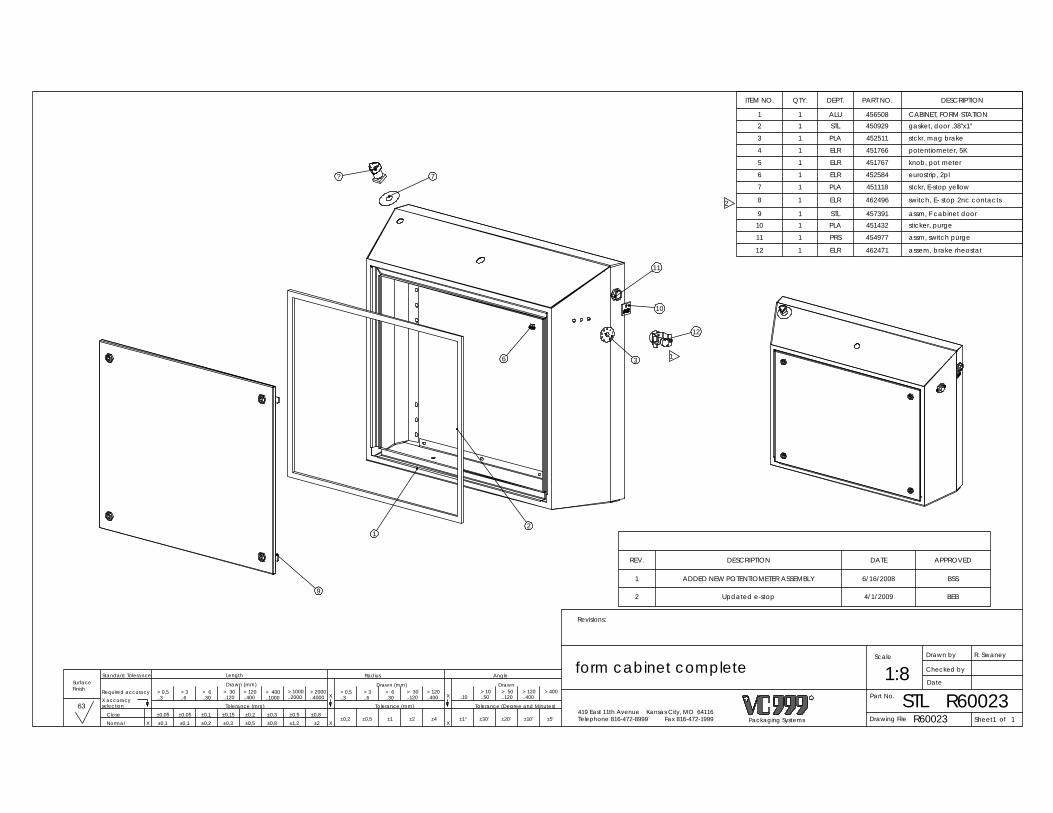
X
63X X
1:8R60023
ofDrawing File R60023
Finish
STL
form cabinet complete
Sheet1Packaging Systems
R
Telephone 816-472-8999 Fax 816-472-1999419 East 11th Avenue Kansas City, MO 64116
Drawn by
Date
Revisions:
Checked by
Scale R. Swaney
Part No.> 3 > 3..6 ..6
±0,1 ±0,2 ±0,3 ±0,5 ±0,8 ±1,2±0,1 ±0,2 ±0,3 ±0,5 ±0,8
±0,1±1° ±30' ±20' ±10' ±5'±0,5±0,2
±2±1 ±4±2
AngleRadiusLength
DrawnDrawn (mm)Drawn (mm)
Tolerance (mm) Tolerance (mm) Tolerance (Degree and Minutes)
> 10 > 50 > 120 > 400..10 ..50 ..120 ..400
> 120> 30> 6> 0,5..400..120..30..3
±0,05 ±0,05 ±0,15
> 0,5..3
> 6..30
> 120> 30..400..120
> 1000 > 2000> 400..2000 ..4000..1000
NormalClose
X accuracyselection
Required accuracy
X
Standard Tolerance
X
Surface
1
ELR
454977
1 462471
PRS
assem, brake rheostat
sticker, purge
12
11 assm, switch purge1
451432
ITEM NO. QTY. DEPT. PART NO. DESCRIPTION
1 1 ALU 456508 CABINET, FORM STATION2 1 STL 450929 gasket, door .38"x1"
3 1 PLA 452511 stckr, mag brake
4 1 ELR 451766 potentiometer, 5K
5 1 ELR 451767 knob, pot meter
6 1 ELR 452584 eurostrip, 2pl
7 1 PLA 451118 stckr, E-stop yellow
8 1 ELR 462496 switch, E- stop 2nc contacts
9 1 STL 457391 assm, F cabinet door10 1 PLA
REV. DESCRIPTION DATE APPROVED
1 ADDED NEW POTENTIOMETER ASSEMBLY 6/16/2008 BSS
2 Updated e-stop 4/1/2009 BEB
?
9
1
7
11
10
12
36
21
2

1
REVISIONS
REV. DESCRIPTION DATE APPROVED
1 WAS M 10 X 50 NOW M10 X 60 12/3/2008 BEB
21
6
12
168
2
18
23
107
24
14
31
11
4
15
13
19
17
5
9
20
22
1
ITEM NO. QTY. DEPARTMENT PART NO. DESCRIPTION1 1 RSA R61955 mnt, die lft cyl V2 1 RSA R61951 plt, die lft rck mnt3 1 PRS 455150 cyl, 63x200 ISO 64314 1 RSA R65787 mount, die lift pltfm V5 2 RSA R61958 shaft, guide die lft6 2 RSA R62123 mnt, die lft shaft7 2 RSA R61952 mnt, gr rack die lft8 2 RSA R61950 rack, gear 12 DP 2259 2 FBR 455149 brg, LN 25mm RD car10 2 RSA R61802 gear, spur 12 DP SP11 2 FBR 450893 bearing, 20x47mm ball12 2 FSC 455779 ring, retn int 40mm13 1 RSA R65786 pad, wear, die lock14 2 PRS 454706 fit, 1/2x3/8npt ST15 4 FSC 457671 screw, M8x35 SHCS16 4 FSC 450806 screw, M6x12 SHCS17 4 FSC 450803 screw, M6x20 SHCS18 4 FSC 451649 M8x25 FHSCS19 1 FSC 450934 screw, M10x60 SHCS20 4 FSC 454049 screw, M12x40 HHCS21 2 FSC 450897 washer, M12 fl reg22 2 FSC 453364 screw, M12x30 HHCS23 2 FSC 457033 key stock, 5x5x25mm24 4 FSC 463032 screw, SH 10x8xM8
OP SIDE IN FORM STATIONUT SIDE IN SEAL STATION
UT SIDE IN FORM STATIONOP SIDE IN SEAL STATION
ofSheet1Packaging Systems
R
Telephone 816-472-8999 Fax 816-472-1999419 East 11th Avenue Kansas City, MO 64116
Drawn by
Date
Revisions:
Checked by
Scale B. SARSFIELD
Part No.> 3 > 3..6 ..6
±0,1 ±0,2 ±0,3 ±0,5 ±0,8 ±1,2±0,1 ±0,2 ±0,3 ±0,5 ±0,8
±0,1±1° ±30' ±20' ±10' ±5'±0,5±0,2
±2±1 ±4±2
AngleRadiusLength
DrawnDrawn (mm)Drawn (mm)
Tolerance (mm) Tolerance (mm) Tolerance (Degree and Minutes)
> 10 > 50 > 120 > 400..10 ..50 ..120 ..400
> 120> 30> 6> 0,5..400..120..30..3
±0,05 ±0,05 ±0,15
> 0,5..3
> 6..30
> 120> 30..400..120
> 1000 > 2000> 400..2000 ..4000..1000
NormalClose
X accuracyselection
Required accuracy
Standard Tolerance
X X X
X
1DLM 463037X
assm, die lift cyl V - improved 1:8
Drawing File 463037
Finish
63
Surface 11/5/08

ofPackaging Systems
R
Telephone 816-472-8999 Fax 816-472-1999419 East 11th Avenue Kansas City, MO 64116
Drawn by
Date
Checked by
Scale M. Vogler
Part No.
Sheet1
1:2
Drawing File
assm, die lift link
DLM456151
4561511
8
3
4
1
2
7
65
9
462227 M12X20 set screw 1
8 FSC 457430 washer, M6 1
9 FSC 451066 nut, M6 hex reg lk 1
ITEM NO. Department PART NUMBER DESCRIPTION extended/QTY.
1 DLM 463214 assm, die lft link mnt improved 1
2 DLM 459076 assm, die lft link cyl 1
3 FSC 450897 washer, M12 fl reg 2
4 RSA R63015 screw, 1/2x78 SHCS SP 2
5 DLM 464212 assm, die lft link sub - imp 1
6 FSC 455416 screw, M10x20 FHSC 1
7 FSC
REVISIONS
REV. DESCRIPTION DATE APPROVED1 Cleaned up sub-assemblies 5/4/2009 BEB
2 Updated part numbers to new assm numbers 6/1/2009 BEB

R
Telephone 816-472-8999 Fax 816-472-1999419 East 11th Avenue Kansas City, MO 64116
Drawn by
Date
463214
Checked by
Scale B. Sarsfield
1:3Part No. 463214DLM
assm, die lft link mnt improved
Drawing File ofSheet1 1Packaging Systems
12/16/08
2
2
REVISIONS
REV. DESCRIPTION DATE APPROVED
1 Removed items to set-up sub assemblies 6-1-09 BEB
2 RSA R62126 was RSA R6632; RSA R62125 was RSA R66319 11/3/2009 BEB
1
3
2
109
4
6
7
8
5
11
ITEM NO. QTY. DEPARTMENT PART NO. DESCRIPTION1 1 RSA R62126 mnt, die lift lk link2 1 RSA R62124 mnt, die lft cyl lck3 1 FBR 453469 bearing, 30x62m BALL4 1 RSA R62125 shaft, die lft lck pin5 1 FSC 451598 ring, retn ext 30mm6 1 RSA R62128 shaft, die lk cyl mnt7 2 FSC 451229 screw, M8x35 HHCS8 2 FSC 450848 washer, M8 fl reg 9 1 FBR 457757 brg, BUSH 30x38x20mm
10 1 RSA R65150 plate, die lock strike11 2 FSC 450900 M6x10 FHSCS

1
B. BorchardtBEB
Packaging Systems
R
Telephone 816-472-8999 Fax 816-472-1999419 East 11th Avenue Kansas City, MO 64116
Drawn by
Date
Checked by
Scale
Part No.
1:1DLM 464212
assm, die lft link sub - imp
Drawing File 464212 ofSheet1
6-1-09
REVISIONS
REV. DESCRIPTION DATE APPROVED
1 Corrected said in-lbs my mistake should have been ft-lbs 9/1/2009 BEB
1
5
ATTACH WITH 55 ft-lbs OF TORQUE
2 4
6
3
1
ITEM NO. QTY. DEPARTMENT PART NO. DESCRIPTION1 1 RSA R65893 link, die lft pltfm improvd2 1 RSA R61948 pin, die lft locking3 1 RSA R63036 whel, die lock 62x174 1 FBR 457632 brg, BUSH 25x35x16fl5 1 FSC 450830 nut, M12 hex thin6 1 RSA R65892 pin, die lk cyl mnt - improvd
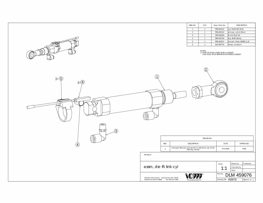
ITEM NO. QTY. Dept./Part No. DESCRIPTION
1 1 PRS 455151 cyl, 25x50 ISO 6432
2 1 PRS 455152 rod eye, cyl rd 25mm
3 2 PRS 456066 fit, 6x1/8npt 90
4 1 FBR 459765 brg, BUSH sliding
5 1 PRS 464527 bracket, Festo SMBR_8_25
6 1 ELR 455778 sensor, rd switch
REVISIONS
REV. DESCRIPTION DATE APPROVED
1 Changed Bracket and sensor to eliminate use of the 180 deg. sensor 9/1/2009 ADB
NOTES:1.) PART (6) IS INCLUDED WITH CYLINDER AND ALSO SOLD SEPARATE FOR REPLACEMENT
6
2
1
3
51
4
1
ofSheet1Packaging Systems
R
Telephone 816-472-8999 Fax 816-472-1999419 East 11th Avenue Kansas City, MO 64116
Drawn by
Date
Revisions:
Checked by
Scale
459076
R. Swaney
DLMPart No. 4590761:1
Drawing File
assm, die lft link cyl
1

REVISIONSREV. DESCRIPTION DATE APPROVED
B. BorchardtBEB
Packaging Systems
R
Telephone 816-472-8999 Fax 816-472-1999419 East 11th Avenue Kansas City, MO 64116
Drawn by
Date
Checked by
Scale
Part No.
1:1ELR 463908
assm, switch safety
Drawing File 463908 ofSheet1 1
3-31-09
2 1
ITEM NO. QTY. DEPARTMENT PART NO. DESCRIPTION1 1 ELR 462475 switch, safety 2 no contacts2 1 ELR 462603 cable, M8 x 10M 4 pin

Sheet1Packaging Systems
R
Telephone 816-472-8999 Fax 816-472-1999419 East 11th Avenue Kansas City, MO 64116
Drawn by
Date
Checked by
Scale B. SARSFIELD
Part No.> 3 > 3..6 ..6
±0,1 ±0,2 ±0,3 ±0,5 ±0,8 ±1,2±0,1 ±0,2 ±0,3 ±0,5 ±0,8
±0,1±1° ±30' ±20' ±10' ±5'±0,5±0,2
±2±1 ±4±2
AngleRadiusLength
DrawnDrawn (mm)Drawn (mm)
Tolerance (mm) Tolerance (mm) Tolerance (Degree and Minutes)
> 10 > 50 > 120 > 400..10 ..50 ..120 ..400
> 120> 30> 6> 0,5..400..120..30..3
±0,05 ±0,05 ±0,15
> 0,5..3
> 6..30
> 120> 30..400..120
> 1000 > 2000> 400..2000 ..4000..1000
NormalClose
X accuracyselection
Required accuracy
Standard Tolerance
X X X
X
1
X
1:1FTR
assm, 5/8" k-chain opener sprocket
462636462636 of
Finish
63Drawing File
Surface 10/8/08
REVISIONSREV. DESCRIPTION DATE APPROVED
1 Changed pin size was 3x6 now 3x12 12/6/2010 BEB
8
1
3
6
7
4
5
2
1
ITEM NO. QTY. DEPARTMENT PART NO. DESCRIPTION1 1 RSA R65495 sprkt, opnr-5/8"chain, sqz knife PR zip 2 2 FSC 452603 int. snap ring 47mm3 3 FBR 462634 Bearing, BALL K-chain4 1 RSA R65497 shaft, opener sprkt5 1 RSA R65498 ring, sprocket retainer6 1 FSC 462635 23mm external snap ring7 1 RSA R65496 ring, opener bevel8 1 FSC 460489 pin, dowel 3x12mm

ofSheet1Packaging Systems
R
Telephone 816-472-8999 Fax 816-472-1999419 East 11th Avenue Kansas City, MO 64116
Drawn by
Date
Checked by
Scale
Drawing File 1
R65747Part No.
assm., main F infeed roller 420 1:2
R65747
BEBB. Borchardt
FUG6-12-09
3
1
2
1
1ITEM NO. QTY. DEPARTMENT PART NO. DESCRIPTION
1 1 RSA R65748 main form infeed roll. 420 - 5/8 chain2 2 RSA R66363 hub, inf.roll bush.70mm3 4 FSC M6x35 screw, M6x35 FHSC
REVISIONS
REV. DESCRIPTION DATE APPROVED
1 Redesign 6/22/2009 BEB

6
2
1
3
4
5
ITEM NO. QTY. DEPARTMENT PART NO. DESCRIPTION1 1 ELR 451183 sensor, water pressure2 1 PRS 451620 fit, 1/8nptf T union3 1 PRS 451336 fit, 1/8npt close np4 1 PRS 451108 valve, check 1/8" nptf5 1 PRS 451492 fit, 1/8nptx1/4npt6 1 PRS 450989 fit, 8x1/8npt ST
Packaging Systems
R
Telephone 816-472-8999 Fax 816-472-1999419 East 11th Avenue Kansas City, MO 64116
Drawn by
Date
Revisions:
Checked by
Scale J. Romfo
Part No.
1:1PRS 454978
assm, sensor water pressure
Drawing File 454978 ofSheet1 1

REVISIONSREV. DESCRIPTION DATE APPROVED
Packaging Systems
R
Telephone 816-472-8999 Fax 816-472-1999419 East 11th Avenue Kansas City, MO 64116
Drawn by
Date
Checked by
Scale M. Vogler
Part No.
1:1.5PRS 456200
assm, valv soln 5/3v
Drawing File 456200 ofSheet1 1
4
5
2
7
6
3
1
ITEM NO. QTY. DEPARTMENT PART NO. DESCRIPTION1 1 PRS 455314 valv, soln 5/3 24dc2 2 ELR 455315 cabl, sol valv 5/3v3 2 RSA R62459 spcr, 8mmidx6mmlg4 2 PRS 455925 fit, 1/2x3/8npt Y ST5 2 FSC 450899 screw, M6x40 SHCS6 1 PRS 450990 fit, 1/2x1/2npt ST7 2 PRS 451824 muflr, 3/8 npt w/FC

REVISIONS
REV. DESCRIPTION DATE APPROVED
1 Changed from spacer to flat washer 8/16/2010 BEB
1
ADB
Packaging Systems
R
Telephone 816-472-8999 Fax 816-472-1999419 East 11th Avenue Kansas City, MO 64116
Drawn by
Date
Checked by
Scale
Part No.> 3 > 3..6 ..6
±0,1 ±0,2 ±0,3 ±0,5 ±0,8 ±1,2±0,1 ±0,2 ±0,3 ±0,5 ±0,8
±0,1±1° ±30' ±20' ±10' ±5'±0,5±0,2
±2±1 ±4±2
AngleRadiusLength
DrawnDrawn (mm)Drawn (mm)
Tolerance (mm) Tolerance (mm) Tolerance (Degree and Minutes)
> 10 > 50 > 120 > 400..10 ..50 ..120 ..400
> 120> 30> 6> 0,5..400..120..30..3
±0,05 ±0,05 ±0,15
> 0,5..3
> 6..30
> 120> 30..400..120
> 1000 > 2000> 400..2000 ..4000..1000
NormalClose
X accuracyselection
Required accuracy
Standard Tolerance
X X X
X 464945ofDrawing File
PRS
assm, die lift cyl manifold, form 1:1X
464945
Finish
63
Sheet1
A. Becker
Surface 12/09/2009
2
3
4
1
1
ITEM NO. QTY. DEPARTMENT PART NO. DESCRIPTION1 1 RSA R66680 manifold, die lift cyl2 6 PRS 454706 fit, 1/2x3/8npt ST3 5 PRS 464947 plug, 3/8 NPT, hex head4 2 FSC 450939 washer M8 flat wide

BEB
Packaging Systems
R
Telephone 816-472-8999 Fax 816-472-1999419 East 11th Avenue Kansas City, MO 64116
Drawn by
Date
Checked by
Scale
Part No.
1:3FUG 463744
assm,flm rlr 420
Drawing File 463744 ofSheet1 1
B. Borchardt
3-2-09
REVISIONSREV. DESCRIPTION DATE APPROVED
2
2
4
3
4
1
ITEM NO. QTY. DEPARTMENT PART NO. DESCRIPTION1 1 RSA R60073 infeed back core 4202 2 FUG R60072 film roll set collar3 1 RSA R62158 rolr, tensn arm 4594 2 FBR 450893 bearing, 20x47mm ball

10
11
6
4
7
3
5
1
22
8
9
12
M6x25 SHCSFSC450826212
screw, M6x90 SHCSFSC450984411
fit, 1nptfx1.25nptmR
ITEM NO. 459/QTY. Dept./Part No. DESCRIPTION
1 1 VAR 455290 valv, vac phnx 1.25p
2 2 PRS450989 fit, 8x1/8npt ST
3 1 RSA R621484 1 VAR 450932 fit, 1barx1npt h brb
5 1 ORR 458215 oring, 50.8x2.38 buna
6 1 FSC451252 clamp, worm 1" hose
7 1 VAR451086 street el. 90 deg 1"
8 1 PRS 454706 fit, 1/2x3/8npt ST
9 1 VAR 454704 fit, 3/8nptfx1npt
10 1 VAR457714
REVISIONS
REV. DESCRIPTION DATE APPROVED
1 Added Hardware 4/29/2009 BEB
ofSheet1Packaging Systems
R
Telephone 816-472-8999 Fax 816-472-1999419 East 11th Avenue Kansas City, MO 64116
Drawn by
Date
Checked by
Scale JGR
Part No.
1:3VAR 461669
assm, F vac vlv S version
Drawing File 461669 1

REV. DESCRIPTION DATE APPROVED
REVISIONS
General Table
ASSEMBLY NUMBER DESCRIPTION ITEM 11 PART NUMBER
STL 463263 650 KNEE FREE 285 RSA R62418STL 463264 650 KNEE FREE 320 RSA R62419STL 463265 650 KNEE FREE 355 RSA R62420STL 466262 650 KNEE FREE 420 RSA R62421
STL 463266 650 KNEE FREE 459 RSA R62422STL 463267 650 KNEE FREE 520 RSA R62423STL 463268 650 KNEE FREE 560 RSA R62238STL 463269 650 KNEE FREE 620 RSA R62593STL 463270 650 KNEE FREE 720 RSA R62424STL 463272 650 KNEE FREE 285 PIN GAS RSA R62425STL 463273 650 KNEE FREE 320 PIN GAS RSA R 62426STL 463274 650 KNEE FREE 355 PIN GAS RSA R62427STL 463271 650 KNEE FREE 420 PIN GAS RSA R62428STL 463275 650 KNEE FREE 459 PIN GAS RSA R62429STL 463276 650 KNEE FREE 520 PIN GAS RSA R62430STL 463277 650 KNEE FREE 560 PIN GAS RSA R62609STL 463278 650 KNEE FREE 620 PIN GAS RSA R62610STL 463279 650 KNEE FREE 720 PIN GAS RSA R62431
BEB
Part No.
Packaging Systems
R
Telephone 816-472-8999 Fax 816-472-1999419 East 11th Avenue Kansas City, MO 64116
Drawn by
Date
Checked by
Scale
1:9650 KN FR K-CHAIN
B. Borchardtassm, knfr 650 LONG
Drawing File 1ofSheet1
1-5-09
14
12
18
19
2120
1
17
2
5
4
716
11
15
8
1
12
9
6
3
10
6
13
ITEM NO. QTY. DEPARTMENT PART NO. DESCRIPTION1 2 RSA R61276 frame, kn fr 650mm2 4 RSA R65908 assm, K-chain guide 650 kf3 20 FSC 450806 screw, M6x12 SHCS4 4 RSA R60911 chain guard standoff5 4 FSC 450802 M8x30 CPSS6 8 FSC 450804 screw, M8x30 SHCS7 2 RSA R61322 OP/UT chain guard 6508 4 FSC 450953 screw, M8x16 FHSCS9 2 ELR 451044 tie, cable 11" w/hole
10 2 FSC 450983 screw, M5x10 SHCS11 2 RSA r62421 cross piece 420 1-612 2 ALU R61278 cover, knee free 65013 2 ELR 451024 wire, 14 AWG 5 con blue14 4 ELR 451818 wire, 22 AWG 2 con gr15 2 RSA R60005 att.block kneefree L16 2 RSA R60068 att.block knee free17 4 FSC 450978 M5x10 FHSCS18 1 ELR 452309 assm, heater plug19 2 PRS 450904 tube, 8mm blue20 1 PRS 450993 tube, 1/2" clear21 1 PRS 450902 tube, 4mm clear

10 12
14
3
98
11
7
71
15 16
2
16
15
17
187
19
1
3
4
7
6
5
13
3
ITEM NO. QTY. DEPARTMENT PART NO. DESCRIPTION1 2 RSA R63811 sprt spcr shrt mchn2 2 RSA R64392 mnt, shrt mach pump 4203 4 RSA R63810 endcap, suprt spcr4 4 RSA R63812 caster mount5 4 STL 460953 caster, 5"x2" swivel6 2 ALU R63813 cvr,knee free shrt mchn7 16 FSC 457484 Screw flat hd Soc M8x308 16 FSC 450848 washer M8 flat9 16 FSC 455915 nut, M8 hex lk
10 16 FSC 451034 washer M10 flat11 8 FSC 455922 screw, M8x40 SHCS12 16 FSC 457892 screw, M10x30 SHCS13 16 FSC 450847 Hex Head CS M8 - 1.25 x 3014 16 FSC 451034 M10 flat washer15 11 FSC 451229 screw, M8x35 HHCS16 11 FSC 450939 washer, M8 fl os17 4 FSC 451629 screw, M6x12 HHCS18 4 RSA R60910 ft. extension19 1 ALU 462191 pan, 650 loading SS, 420
6
2
Not shown: STL 452332
2
REVISIONS
REV. DESCRIPTION DATE APPROVED
1 HARDWARE FOR ITEMS 11&13 WAS 8mm, ADDED LOADING PAN 11/19/08 BS
2 Added edge trim; ALU 464642 was ALU R63813 10/15/2009 BEB
3 Converted PN ALU 464642 to ALU R63813 Old PN new design; corrected PN on pump mount part 11/5/2009 BEB
4 Removed chute, end plate, legs and side pannels 2/23/2010 BEB
5 Removed PLA 464705 4/22/2010 BEB
6 Changed screw was FSC 450953 M8x16 7/22/2010 BEB
7 Changed Hardware 10/13/2010 BEB
Note location of items 1, 2 &3
Note loctionof items 4 &5
460984STL
Sheet1Packaging Systems
R
Telephone 816-472-8999 Fax 816-472-1999419 East 11th Avenue Kansas City, MO 64116
Drawn by
Date
Checked by
Scale S. WILLCOTT
460984Drawing File
1:15
of
assm, shrt mchn kit, 420Part No.
1

ofSheet12
-
Packaging Systems
R
Telephone 816-472-8999 Fax 816-472-1999419 East 11th Avenue Kansas City, MO 64116
Drawn by
Date
Checked by
Scale B. SARSFIELD
Part No.
1:22STL
assm, seal st 420 V - K chain
463005463005Drawing File
11-24-08
REVISIONS
REV. DESCRIPTION DATE APPROVED
1 Updated water valve, e-stop & safety sensors 3/31/2009 BEB
2 Added ALU 464736 Mac valve cover 11/17/2009 BEB
3 Removed MAC valve replaced with Festo and manifold 12/15/2009 ADB
4 Added power switch for assm ref only 2/4/2010 ADB
5 Changed sprocket assy. & screw ; added spacer 9/30/2010 BEB
67
7
6
3529
34
26
3128
47
4238
22
41
27
1514
18
17
44
20
33
1232 10
48
9
39
49
25
3
37
443
36
8
45
2146
11
519 24
30
2
23
50
51
4055
5653
54
57
68
6469
65
1
71
58
59
3
704
552

1
11
Packaging Systems
R
Telephone 816-472-8999 Fax 816-472-1999419 East 11th Avenue Kansas City, MO 64116
Drawn by
Date
Checked by
Scale
Part No.
1:25STL 463005
assm, seal st 420 V - K chain
Drawing File 463005 ofSheet22
B. SARSFIELD-
11-24-08
3
3
ITEM NO. QTY. DEPARTMENT PART NO. DESCRIPTION1 1 STL 457875 assm, main frm S 4202 2 RSA R62394 shaft, die lft gr 4203 1 FUG R62344 assm, fnl rlr tp web 4204 1 FTR 462963 assm, main drv 420VD -K5 1 STL R60010 assm, utility blk OP6 1 STL R60008 assm, utility blk UT7 2 DLM 456151 assm, die lift link8 2 DLM 463037 assm, die lift cyl V - improved9 1 PRS 456134 assm, valv soln 3/2
10 1 RSA R60005 att.block kneefree L11 1 RSA R60068 att.block knee free12 2 PRS 451299 fit, 1/4barx1/8nptST13 2 RSA R60911 chain guard standoff14 2 FSC 454451 knob, 7 lobed M815 2 RSA R62460 brkt, pneumatic cvr mnt 16 1 ALU 455894 cover, pneumatic controls17 1 RSA R62450 plt, valv mnfld ST18 4 RSA R62459 spcr, 8mmidx6mmlg19 4 ELR 463908 assm, switch safety20 2 RSA R65278 standoff, idler sprocket 5/8" chain21 4 FTR 466035 assm, idlr sprkt 18 tooth (5/8 chain) up22 1 RSA R60268 left column cap23 1 PLA 463899 assm, top web R cap24 1 RSA R60187 OP NF tall mount 25 1 FSC 450947 M8 ball plunger26 1 RSA R60188 UT NF tall mount27 4 FSC 451374 screw, M8x10 HHCS28 4 FSC 450812 pin, dowel 6x40mm 29 8 FSC 451634 M8x80 SHCS30 16 FSC 450806 screw, M6x12 SHCS31 8 FSC 450804 screw, M8x30 SHCS32 4 FSC 451414 M8x60 SHCS33 4 FSC 462269 screw M12 x 110 SHCS34 4 FSC 451246 screw, M12x25 SHCS35 4 FSC 455572 nut, 1/2-20 hex thin36 18 FSC 450897 washer, M12 fl reg37 12 FSC 453245 M12x35 SHCS38 4 FSC 451067 washer, M6 fl reg
ITEM NO. QTY. DEPARTMENT PART NO. DESCRIPTION39 4 FSC 451629 screw, M6x12 HHCS40 2 FSC 451036 screw, M6x120 SHCS41 4 FSC 450802 M8x30 CPSS42 4 FSC 451649 M8x25 FHSCS43 3 ELR 455778 sensor, rd switch 44 2 RSA R65279 standoff, chain tensioner sprkt 5/8"45 2 RSA R64298 nut, M12 T-slot S.S.46 2 RSA R64325 screw, chn ten adj47 4 FSC 450830 nut, M12 hex thin48 1 ALU 458821 end cap form/seal 420 dp49 2 RSA R65277 assm, K-chain guide seal st.50 1 PRS 463887 assm, water valve51 1 ELR 462496 switch, E- stop 2nc contacts52 1 RSA r66317 screen cover53 2 RSA r66316 mount, screen cover54 2 FSC 450938 6mmx20mm long pin55 4 FSC 450801 M6x30 SHCS56 4 FSC 450873 nut, M6 hex reg57 4 ORR 455327 oring, 7x1.5mm buna58 1 RSA R60079 right side top web59 2 RSA R60182 upper web sys. attach. bar60 2 RSA R60178 column attachment bar61 4 FSC 450948 screw, M5x16 FHSCS62 1 FSC 451297 screw M5 x 25 SHCS63 9 FSC 451374 Hex Head CS M8 - 1.25 x 1064 11 FSC 450848 washer M8 flat65 1 RSA R60016 left side top web66 1 RSA R65170 plate, plug mnt- conf.567 1 PRS 456200 assm, valv soln 5/3v68 1 PRS 464946 assm, die lift cyl manifold, seal69 2 FSC 461411 Hex Head CS M8 - 1.25 x 4070 1 ELA 500919 switch, main pwr71 4 RSA R67107 spacer, idler sprocket

4
7
13
9
10
5
8
2
6
7
6
Drawing File 457875 ofSheet1Packaging Systems
R
Telephone 816-472-8999 Fax 816-472-1999419 East 11th Avenue Kansas City, MO 64116
Drawn by
Date
Checked by
Scale M. Vogler
Part No.
1:10STL 457875
assm, main frm S 420
1
pin, dowel 6x40mm FSC 450812811lower cross member 420RSA R60086210
upper cross member 420
ITEM NO. 420/QTY. Dept./Part No. DESCRIPTION
1 1 ALU 456509 WRAP, SEAL UTILITY
2 1 RSA R62353 frm, seal side OP3 1 STL R60024 seal cabinet complete
4 1 RSA R62354 frm, seal side UT5 4 STL R60022 foot assembly RS/K1
6 25 FSC450848 washer, M8 fl reg
7 28 FSC 451229 screw, M8x35 HHCS
8 4 RSA R60088 foot mount form/seal9 2 RSA R60087
REVISIONS
REV. DESCRIPTION DATE APPROVED
1 Turned over foot mounting block. 5/14/2009 BEB

R60024Sheet1Packaging Systems
R
Telephone 816-472-8999 Fax 816-472-1999419 East 11th Avenue Kansas City, MO 64116
Drawn by
Date
Checked by
Scale J. Romfo
Drawing File of
Part No.
1:8seal cabinet complete
STLR60024 1
ITEM NO. QTY. DEPARTMENT PART NO. DESCRIPTION1 1 ALU 456510 CABINET, SEAL STATION2 1 ELR 451153 strn rlf, PG36x27mm3 1 PLA 451118 stckr, E-stop yellow4 1 STL 450929 gasket, door .38"x1"5 1 STL 457392 assm, S cabinet door6 1 ELA 500919 switch, main pwr7 2 ELA 516651 cap, main switch yellow
REVISIONSREV. DESCRIPTION DATE APPROVED
1 Added reference part numbers 5-27-10 BEB
3
2
4
5
1
67
Note: Items 6& 7 shown for reference only not in this assembly

REVISIONSREV. DESCRIPTION DATE APPROVED
Packaging Systems
R
Telephone 816-472-8999 Fax 816-472-1999419 East 11th Avenue Kansas City, MO 64116
Drawn by
Date
Checked by
Scale B. SARSFIELD
Part No.
1:4FTR 462963
assm, main drv 420VD
Drawing File 462963 ofSheet1 1
4/2/08
4
710
2
65
31
9
8
11
13
12
ITEM NO. QTY. DEPARTMENT PART NO. DESCRIPTION1 1 RSA R62360 mnt, main drv 420 VD2 2 RSA R65276 sprkt, main drv 18 tooth - 5/8 chain3 2 FBR R60011 brg, FL 35mm 4BLT4 1 RSA R62375 shaft, mtr drv 420VD5 2 FSC 450958 key stk, .38x.38x1.36 2 FSC 450952 screw, M8x10 SHSS CP7 1 RSA R62466 brkt, hose clmp8 4 FSC 457892 screw, M10x30 SHCS9 2 FSC 450934 screw, M10x60 SHCS
10 1 FTR 458534 assm, drv mtr vctr11 1 FTR 454619 gearbox, vector 10:112 4 FSC 455932 screw, 3/8x.88 SHCS13 2 FSC 459514 screw, M10x16 HHCS

REVISIONSREV. DESCRIPTION DATE APPROVED
Packaging Systems
R
Telephone 816-472-8999 Fax 816-472-1999419 East 11th Avenue Kansas City, MO 64116
Drawn by
Date
Checked by
Scale M. Vogler
Part No.
1:2FUG R62344
assm, fnl rlr tp web 420
Drawing File R62344 ofSheet1 1
1
5
432
ITEM NO. QTY. DEPARTMENT PART NO. DESCRIPTION1 1 RSA R62344 rolr, fnl top web 4202 2 FSC 450806 screw, M6x12 SHCS3 2 FSC 451067 washer, M6 fl reg4 2 FBR 508359 brg, 10x26mm BALL5 2 RSA R60211 infeed roller center

REVISIONS
ZONE REV. DESCRIPTION DATE APPROVED
Drawing FilePackaging Systems
R
Telephone 816-472-8999 Fax 816-472-1999419 East 11th Avenue Kansas City, MO 64116
Drawn by
Date
Checked by
Scale B. Borchardt
1
Part No. 4660351:1assm, idlr sprkt 18 tooth (5/8 chain) updated
of466035 Sheet1
FTR10-1-10
2
13
4
ITEM NO. QTY. DEPARTMENT PART NO. DESCRIPTION1 1 RSA R67106sprkt, idler 18 tooth - 5/8 chain-upd2 1 FBR 450893 bearing, 20x47mm ball3 1 RSA R60164 gripper open bushing4 1 FSC 452603 int. snap ring 47mm

3
2
1
ITEM NO. QTY. DEPARTMENT PART NO. DESCRIPTION1 1 RSA R60016 left side top web2 1 RSA r60178 column attachment bar3 1 RSA R60182 upper web sys. attach. bar
Packaging Systems
R
Telephone 816-472-8999 Fax 816-472-1999419 East 11th Avenue Kansas City, MO 64116
Drawn by
Date
Revisions:
Checked by
Scale R. Swaney
Part No.> 3 > 3..6 ..6
±0,1 ±0,2 ±0,3 ±0,5 ±0,8 ±1,2±0,1 ±0,2 ±0,3 ±0,5 ±0,8
±0,1±1° ±30' ±20' ±10' ±5'±0,5±0,2
±2±1 ±4±2
AngleRadiusLength
DrawnDrawn (mm)Drawn (mm)
Tolerance (mm) Tolerance (mm) Tolerance (Degree and Minutes)
> 10 > 50 > 120 > 400..10 ..50 ..120 ..400
> 120> 30> 6> 0,5..400..120..30..3
±0,05 ±0,05 ±0,15
> 0,5..3
> 6..30
> 120> 30..400..120
> 1000 > 2000> 400..2000 ..4000..1000
NormalClose
X accuracyselection
Required accuracy
Standard Tolerance
X X X
X X
1:14STL R60016
assm, top web L
Drawing File R60016
SurfaceFinish
63ofSheet11

2
3
1
ITEM NO. QTY. DEPARTMENT PART NO. DESCRIPTION1 1 RSA R60079 right side top web2 1 RSA R60182 upper web sys. attach. bar3 1 RSA r60178 column attachment bar
Packaging Systems
R
Telephone 816-472-8999 Fax 816-472-1999419 East 11th Avenue Kansas City, MO 64116
Drawn by
Date
Revisions:
Checked by
Scale R. Swaney
Part No.> 3 > 3..6 ..6
±0,1 ±0,2 ±0,3 ±0,5 ±0,8 ±1,2±0,1 ±0,2 ±0,3 ±0,5 ±0,8
±0,1±1° ±30' ±20' ±10' ±5'±0,5±0,2
±2±1 ±4±2
AngleRadiusLength
DrawnDrawn (mm)Drawn (mm)
Tolerance (mm) Tolerance (mm) Tolerance (Degree and Minutes)
> 10 > 50 > 120 > 400..10 ..50 ..120 ..400
> 120> 30> 6> 0,5..400..120..30..3
±0,05 ±0,05 ±0,15
> 0,5..3
> 6..30
> 120> 30..400..120
> 1000 > 2000> 400..2000 ..4000..1000
NormalClose
X accuracyselection
Required accuracy
Standard Tolerance
X X X
X X
1:14STL R60079
assm, top web R
Drawing File R60079
SurfaceFinish
63ofSheet11

Packaging SystemsTelephone 816-472-8999 Fax 816-472-1999419 East 11th Avenue Kansas City, MO 64116
Drawn by
Date
Revisions:
Checked by
Scale J. Romfo
Part No.
1:2STL R60022
foot assembly RS/K1
Drawing File R60022 ofSheet1 1
4
1
2
3
ITEM NO. QTY. DEPARTMENT PART NO. DESCRIPTION LOCATION MATERIAL MATERIAL P/N
1 1 STL 512777 supt, foot K1 U10B60 SS N/A
2 1 FWA 512062 washer for K1/RS foot U10B20 SS N/A3 1 STL 512063 plug, tub 73mm dia U10B30 rubber N/A
4 1 STL 512224 plug, tub 70mm dia U10E10 plastic N/A

ofPackaging Systems
R
Telephone 816-472-8999 Fax 816-472-1999419 East 11th Avenue Kansas City, MO 64116
Drawn by
Date
Checked by
Scale M. Vogler
Part No.
Sheet1
1:2
Drawing File
assm, die lift link
DLM456151
4561511
8
3
4
1
2
7
65
9
462227 M12X20 set screw 1
8 FSC 457430 washer, M6 1
9 FSC 451066 nut, M6 hex reg lk 1
ITEM NO. Department PART NUMBER DESCRIPTION extended/QTY.
1 DLM 463214 assm, die lft link mnt improved 1
2 DLM 459076 assm, die lft link cyl 1
3 FSC 450897 washer, M12 fl reg 2
4 RSA R63015 screw, 1/2x78 SHCS SP 2
5 DLM 464212 assm, die lft link sub - imp 1
6 FSC 455416 screw, M10x20 FHSC 1
7 FSC
REVISIONS
REV. DESCRIPTION DATE APPROVED1 Cleaned up sub-assemblies 5/4/2009 BEB
2 Updated part numbers to new assm numbers 6/1/2009 BEB

R
Telephone 816-472-8999 Fax 816-472-1999419 East 11th Avenue Kansas City, MO 64116
Drawn by
Date
463214
Checked by
Scale B. Sarsfield
1:3Part No. 463214DLM
assm, die lft link mnt improved
Drawing File ofSheet1 1Packaging Systems
12/16/08
2
2
REVISIONS
REV. DESCRIPTION DATE APPROVED
1 Removed items to set-up sub assemblies 6-1-09 BEB
2 RSA R62126 was RSA R6632; RSA R62125 was RSA R66319 11/3/2009 BEB
1
3
2
109
4
6
7
8
5
11
ITEM NO. QTY. DEPARTMENT PART NO. DESCRIPTION1 1 RSA R62126 mnt, die lift lk link2 1 RSA R62124 mnt, die lft cyl lck3 1 FBR 453469 bearing, 30x62m BALL4 1 RSA R62125 shaft, die lft lck pin5 1 FSC 451598 ring, retn ext 30mm6 1 RSA R62128 shaft, die lk cyl mnt7 2 FSC 451229 screw, M8x35 HHCS8 2 FSC 450848 washer, M8 fl reg 9 1 FBR 457757 brg, BUSH 30x38x20mm
10 1 RSA R65150 plate, die lock strike11 2 FSC 450900 M6x10 FHSCS

1
B. BorchardtBEB
Packaging Systems
R
Telephone 816-472-8999 Fax 816-472-1999419 East 11th Avenue Kansas City, MO 64116
Drawn by
Date
Checked by
Scale
Part No.
1:1DLM 464212
assm, die lft link sub - imp
Drawing File 464212 ofSheet1
6-1-09
REVISIONS
REV. DESCRIPTION DATE APPROVED
1 Corrected said in-lbs my mistake should have been ft-lbs 9/1/2009 BEB
1
5
ATTACH WITH 55 ft-lbs OF TORQUE
2 4
6
3
1
ITEM NO. QTY. DEPARTMENT PART NO. DESCRIPTION1 1 RSA R65893 link, die lft pltfm improvd2 1 RSA R61948 pin, die lft locking3 1 RSA R63036 whel, die lock 62x174 1 FBR 457632 brg, BUSH 25x35x16fl5 1 FSC 450830 nut, M12 hex thin6 1 RSA R65892 pin, die lk cyl mnt - improvd

ITEM NO. QTY. Dept./Part No. DESCRIPTION
1 1 PRS 455151 cyl, 25x50 ISO 6432
2 1 PRS 455152 rod eye, cyl rd 25mm
3 2 PRS 456066 fit, 6x1/8npt 90
4 1 FBR 459765 brg, BUSH sliding
5 1 PRS 464527 bracket, Festo SMBR_8_25
6 1 ELR 455778 sensor, rd switch
REVISIONS
REV. DESCRIPTION DATE APPROVED
1 Changed Bracket and sensor to eliminate use of the 180 deg. sensor 9/1/2009 ADB
NOTES:1.) PART (6) IS INCLUDED WITH CYLINDER AND ALSO SOLD SEPARATE FOR REPLACEMENT
6
2
1
3
51
4
1
ofSheet1Packaging Systems
R
Telephone 816-472-8999 Fax 816-472-1999419 East 11th Avenue Kansas City, MO 64116
Drawn by
Date
Revisions:
Checked by
Scale
459076
R. Swaney
DLMPart No. 4590761:1
Drawing File
assm, die lft link cyl
1
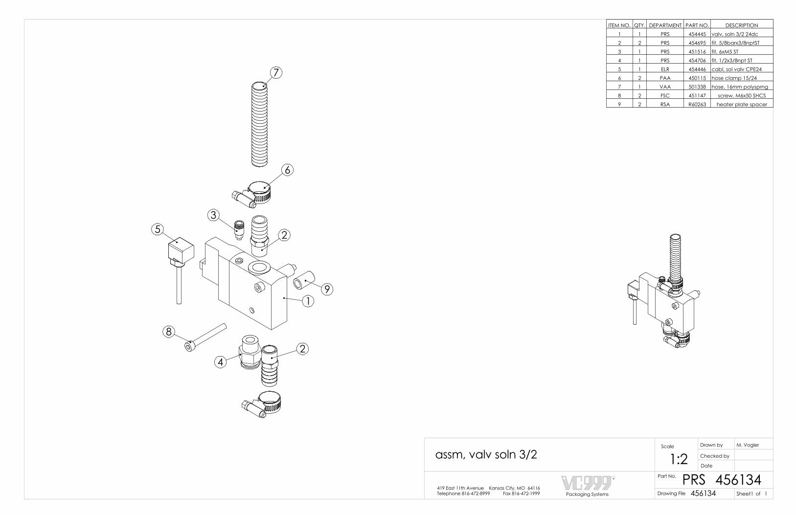
5
9
7
6
2
1
24
8
3
ITEM NO. QTY. DEPARTMENT PART NO. DESCRIPTION1 1 PRS 454445 valv, soln 3/2 24dc2 2 PRS 454695 fit, 5/8barx3/8nptST3 1 PRS 451516 fit, 6xM5 ST4 1 PRS 454706 fit, 1/2x3/8npt ST5 1 ELR 454446 cabl, sol valv CPE246 2 PAA 450115 hose clamp 15/247 1 VAA 501338 hose, 16mm polysprng8 2 FSC 451147 screw, M6x50 SHCS9 2 RSA R60263 heater plate spacer
ofSheet1Packaging Systems
R
Telephone 816-472-8999 Fax 816-472-1999419 East 11th Avenue Kansas City, MO 64116
Drawn by
Date
Checked by
Scale M. Vogler
Part No.
1:2PRS 456134
assm, valv soln 3/2
Drawing File 456134 1
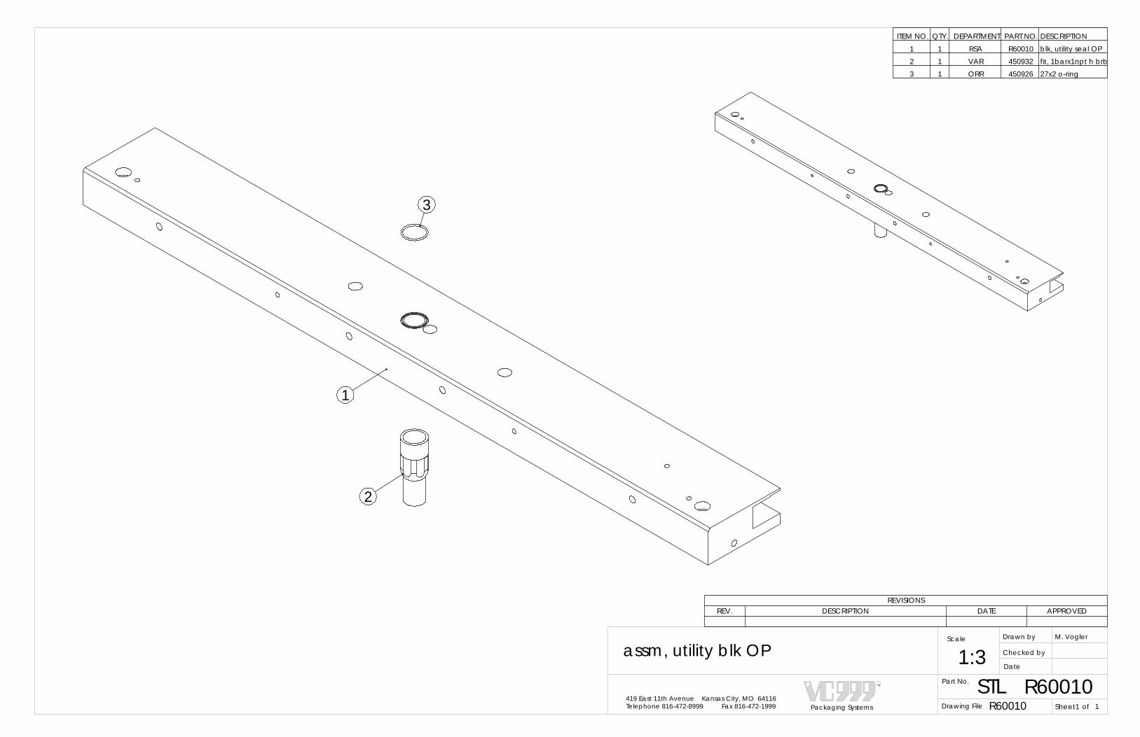
REVISIONSREV. DESCRIPTION DATE APPROVED
Packaging Systems
R
Telephone 816-472-8999 Fax 816-472-1999419 East 11th Avenue Kansas City, MO 64116
Drawn by
Date
Checked by
Scale M. Vogler
Part No.
1:3STL R60010
assm, utility blk OP
Drawing File R60010 ofSheet1 1
1
2
3
ITEM NO. QTY. DEPARTMENT PART NO. DESCRIPTION1 1 RSA R60010 blk, utility seal OP2 1 VAR 450932 fit, 1barx1npt h brb3 1 ORR 450926 27x2 o-ring

1
3
2
4
5 7 6
5
8
A
A
ITEM NO. QTY. Dept./Part No. DESCRIPTION
1 1 RSA R60008 blk, utility seal UT
2 1 VAR 457556 fit, 1barx.75npt BR
3 1 PRS 454398 fit, 5/8barx1/2nptST
4 1 PRS450908 fit, 8x1/4npt 90
5 2 ORR 450925 oring, 10x2mm buna
6 1 ORR 450926 oring, 27x2mm buna
7 1 ORR 453841 oring, 22x2mm buna
8 1 PRS450907 fit, 8x1/4npt ST
REVISIONSREV. DESCRIPTION DATE APPROVED
A change qty. of item 4, was (2), add item 8 (1) 2/20/2006
Packaging Systems
R
Telephone 816-472-8999 Fax 816-472-1999419 East 11th Avenue Kansas City, MO 64116
Drawn by
Date
Checked by
Scale M. Vogler
Part No.
1:3STL R60008
assm, utility blk UT
Drawing File R60008 ofSheet1 1

1
REVISIONS
REV. DESCRIPTION DATE APPROVED
1 WAS M 10 X 50 NOW M10 X 60 12/3/2008 BEB
21
6
12
168
2
18
23
107
24
14
31
11
4
15
13
19
17
5
9
20
22
1
ITEM NO. QTY. DEPARTMENT PART NO. DESCRIPTION1 1 RSA R61955 mnt, die lft cyl V2 1 RSA R61951 plt, die lft rck mnt3 1 PRS 455150 cyl, 63x200 ISO 64314 1 RSA R65787 mount, die lift pltfm V5 2 RSA R61958 shaft, guide die lft6 2 RSA R62123 mnt, die lft shaft7 2 RSA R61952 mnt, gr rack die lft8 2 RSA R61950 rack, gear 12 DP 2259 2 FBR 455149 brg, LN 25mm RD car10 2 RSA R61802 gear, spur 12 DP SP11 2 FBR 450893 bearing, 20x47mm ball12 2 FSC 455779 ring, retn int 40mm13 1 RSA R65786 pad, wear, die lock14 2 PRS 454706 fit, 1/2x3/8npt ST15 4 FSC 457671 screw, M8x35 SHCS16 4 FSC 450806 screw, M6x12 SHCS17 4 FSC 450803 screw, M6x20 SHCS18 4 FSC 451649 M8x25 FHSCS19 1 FSC 450934 screw, M10x60 SHCS20 4 FSC 454049 screw, M12x40 HHCS21 2 FSC 450897 washer, M12 fl reg22 2 FSC 453364 screw, M12x30 HHCS23 2 FSC 457033 key stock, 5x5x25mm24 4 FSC 463032 screw, SH 10x8xM8
OP SIDE IN FORM STATIONUT SIDE IN SEAL STATION
UT SIDE IN FORM STATIONOP SIDE IN SEAL STATION
ofSheet1Packaging Systems
R
Telephone 816-472-8999 Fax 816-472-1999419 East 11th Avenue Kansas City, MO 64116
Drawn by
Date
Revisions:
Checked by
Scale B. SARSFIELD
Part No.> 3 > 3..6 ..6
±0,1 ±0,2 ±0,3 ±0,5 ±0,8 ±1,2±0,1 ±0,2 ±0,3 ±0,5 ±0,8
±0,1±1° ±30' ±20' ±10' ±5'±0,5±0,2
±2±1 ±4±2
AngleRadiusLength
DrawnDrawn (mm)Drawn (mm)
Tolerance (mm) Tolerance (mm) Tolerance (Degree and Minutes)
> 10 > 50 > 120 > 400..10 ..50 ..120 ..400
> 120> 30> 6> 0,5..400..120..30..3
±0,05 ±0,05 ±0,15
> 0,5..3
> 6..30
> 120> 30..400..120
> 1000 > 2000> 400..2000 ..4000..1000
NormalClose
X accuracyselection
Required accuracy
Standard Tolerance
X X X
X
1DLM 463037X
assm, die lift cyl V - improved 1:8
Drawing File 463037
Finish
63
Surface 11/5/08

5
9
7
6
2
1
24
8
3
ITEM NO. QTY. DEPARTMENT PART NO. DESCRIPTION1 1 PRS 454445 valv, soln 3/2 24dc2 2 PRS 454695 fit, 5/8barx3/8nptST3 1 PRS 451516 fit, 6xM5 ST4 1 PRS 454706 fit, 1/2x3/8npt ST5 1 ELR 454446 cabl, sol valv CPE246 2 PAA 450115 hose clamp 15/247 1 VAA 501338 hose, 16mm polysprng8 2 FSC 451147 screw, M6x50 SHCS9 2 RSA R60263 heater plate spacer
ofSheet1Packaging Systems
R
Telephone 816-472-8999 Fax 816-472-1999419 East 11th Avenue Kansas City, MO 64116
Drawn by
Date
Checked by
Scale M. Vogler
Part No.
1:2PRS 456134
assm, valv soln 3/2
Drawing File 456134 1

REVISIONSREV. DESCRIPTION DATE APPROVED
B. BorchardtBEB
Packaging Systems
R
Telephone 816-472-8999 Fax 816-472-1999419 East 11th Avenue Kansas City, MO 64116
Drawn by
Date
Checked by
Scale
Part No.
1:1ELR 463908
assm, switch safety
Drawing File 463908 ofSheet1 1
3-31-09
2 1
ITEM NO. QTY. DEPARTMENT PART NO. DESCRIPTION1 1 ELR 462475 switch, safety 2 no contacts2 1 ELR 462603 cable, M8 x 10M 4 pin

?
9
1
5
46
2
8
1
7
2
ITEM NO. QTY. DEPARTMENT PART NO. DESCRIPTION1 1 PRS 454489 valv, soln 2/2 24dc2 1 PRS 450907 fit, 8x1/4npt ST3 1 RSA R65698 plate, water valve adapter4 2 FSC 454192 screw M4 x 8 SHCS5 2 FSC 450800 screw M8 x 25 SHCS6 2 RSA R62459 spcr, 8mmidx6mmlg7 1 ELR 454491 coil, soln valv 2/28 1 ELR 454490 cabl, sol valv 2/2v9 1 PRS 450908 fit, 8x1/4npt 90
1
REVISIONS
REV. DESCRIPTION DATE APPROVED
1 Removed hose barb replaced with 8mm tube elbow 12/17/2009 ADB
2 Changed screw was 4 x 10 now 4 x 8 11/15/2010 BEB
of
assm, water valveB. Borchardt
BEB
Packaging Systems
R
Telephone 816-472-8999 Fax 816-472-1999419 East 11th Avenue Kansas City, MO 64116
Drawn by
Date
Checked by1:1
463887PRSPart No. 463887
Sheet1Drawing File 1
Scale
-

REVISIONSREV. DESCRIPTION DATE APPROVED
assm, top web R cap
of463899
B. BorchardtBEB
Packaging Systems
R
Telephone 816-472-8999 Fax 816-472-1999419 East 11th Avenue Kansas City, MO 64116
Drawn by
Date
Checked by
1
Scale
PLAPart No. 4638991:1
Drawing File Sheet1
4-1-09
3
1
2
ITEM NO. QTY. DEPARTMENT PART NO. DESCRIPTION1 1 RSA R63566 cap, right column2 1 PRS 459080 fit, 3/8barx3/8nptst3 1 PRS 459031 fit, 1/2x3/4fnpt blk

REVISIONSREV. DESCRIPTION DATE APPROVED
Packaging Systems
R
Telephone 816-472-8999 Fax 816-472-1999419 East 11th Avenue Kansas City, MO 64116
Drawn by
Date
Checked by
Scale M. Vogler
Part No.
1:1.5PRS 456200
assm, valv soln 5/3v
Drawing File 456200 ofSheet1 1
4
5
2
7
6
3
1
ITEM NO. QTY. DEPARTMENT PART NO. DESCRIPTION1 1 PRS 455314 valv, soln 5/3 24dc2 2 ELR 455315 cabl, sol valv 5/3v3 2 RSA R62459 spcr, 8mmidx6mmlg4 2 PRS 455925 fit, 1/2x3/8npt Y ST5 2 FSC 450899 screw, M6x40 SHCS6 1 PRS 450990 fit, 1/2x1/2npt ST7 2 PRS 451824 muflr, 3/8 npt w/FC

2
4
1
3
1
ITEM NO. QTY. DEPARTMENT PART NO. DESCRIPTION1 1 RSA R66680 manifold, die lift cyl2 6 PRS 454706 fit, 1/2x3/8npt ST3 5 PRS 464947 plug, 3/8 NPT, hex head4 2 FSC 450939 washer M8 flat wide
REVISIONS
REV. DESCRIPTION DATE APPROVED
1 Changed from Spacer to washer 8/16/2010 BEB
ADB
Packaging Systems
R
Telephone 816-472-8999 Fax 816-472-1999419 East 11th Avenue Kansas City, MO 64116
Drawn by
Date
Checked by
Scale A. Becker
Part No.
1:1PRS
assm, die lift cyl manifold, seal
464946464946Drawing File ofSheet1 1
12/09/2009
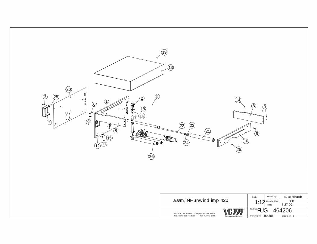
Packaging Systems
R
Telephone 816-472-8999 Fax 816-472-1999419 East 11th Avenue Kansas City, MO 64116
Drawn by
Date
Checked by
Scale
Part No.
1:12FUG 464206
assm, NF unwind imp 420
Drawing File 464206 ofSheet1 2
B. BorchardtBEB
5-27-09
814
9
6
25
10
2123
24
22
5
19
13
1
8
18
17
2
151112
6
9
20
253
716
26

Packaging Systems
R
Telephone 816-472-8999 Fax 816-472-1999419 East 11th Avenue Kansas City, MO 64116
Drawn by
Date
Checked by
Scale
Part No.
1:8FUG 464206
assm, NF unwind imp 420
Drawing File 464206 ofSheet2 2
B. BorchardtBEB
5-27-09
ITEM NO. QTY. DEPARTMENT PART NO. DESCRIPTION1 1 RSA R60019 NF top web plate2 1 PLC 453382 assm, cd mnfld 4 pos3 4 FSC 451147 screw, M6x50 SHCS4 2 RSA R60076 seal infeed roll. core 355/4205 2 FUG 456292 assm, sl infd rolr 355/4206 4 FSC 450800 screw, M8x25 SHCS7 1 STL R60438 brake cover8 2 RSA R60029 hood frame side 355/4209 8 FSC 450826 M6x25 SHCS
10 1 RSA R60028 hood frame from11 4 FSC 451229 screw, M8x35 HHCS12 4 FSC 450848 washer, M8 fl reg 13 1 ALU R62105 hood, seal st 355.42014 4 RSA R60195 pneum.manifold spacer15 1 ELR 451247 plug, thread PG-1616 1 ELR 451000 plug, cable 7pin M17 2 ALU 457721 cvr, plug NF unwnd plt18 8 FSC 450895 screw, M3x6 PHSL 19 4 FSC 450948 screw, M5x16 FHSC20 1 ALU R60193 top web back plate cover21 1 RSA R61889 rolr, tensn arm 42022 1 RSA R62800 shaft, flm rlr sprt S 355.42023 2 RSA R62794 hub, idlr rollr bush24 2 FUG R60184 film trapieze set collar25 2 FSC 451653 screw, M6x25 FHSC26 1 FUG 463852 assm, tensn arm (imprvd) 420

Telephone 816-472-8999 Fax 816-472-1999
PLC
Scale
Part No.
Drawn by M. Vogler
419 East 11th Avenue Kansas City, MO 64116
1.5:1Date
453382
assm, cd mnfld 4 pos
Drawing File 453382 ofSheet1Packaging Systems
R
Checked by
1
5
6
2
4
2
1
3
Note: If code dater is installed on machine then FSC 450951 will be replaced with a pair of PRS 451159 for each code dater.
7
Code Dater Version
REVISIONSDATEREV. APPROVED
1 2-11-10DESCRIPTION
Updated drawing for Code dater option BEB
ITEM NO. 0 pos fc/QTY. 2 pos fc/QTY. DEPT. PART NO. DESCRIPTION
1 1 1 RSA R61334 manifold, code dtr 42 4 4 PRS 450989 fit, 8x1/8npt ST
3 2 2 FSC 452182 plug, 1/8 NPT
4 2 2 FSC 451031 screw, M5x20 SHCS
5 8 4 FSC 450951 screw, M5x8 PHSL6 1 1 PRS 456613 fit, 8x1/8npt FC 90
7 - 4 PRS 451159 fit, 4xM5 SS

REVISIONSREV. DESCRIPTION DATE APPROVED
1 Changed roller & added 24mm spacer 12/16/2004 MAV
ITEM NO. 420 seal/QTY. DEPT. PART NO. DESCRIPTION1 1 RSA R62346 rolr, fnl top web 520
2 2 RSA R62561 bush, flm rolr 4mm3 2 RSA R63034 spacr, 1-1/4"ODx24mm 1
1
2
3
1
2
3
ofSheet1Packaging Systems
R
Telephone 816-472-8999 Fax 816-472-1999419 East 11th Avenue Kansas City, MO 64116
Drawn by
Date
Checked by
Scale M. Vogler
Part No.
1:1FUG 456292
assm, sl infd rolr 355/420
Drawing File 456292 1

ofSheet12Packaging Systems
R
Telephone 816-472-8999 Fax 816-472-1999419 East 11th Avenue Kansas City, MO 64116
Drawn by
Date
Checked by
Scale B. SARSFIELD
Part No.> 3 > 3..6 ..6
±0,1 ±0,2 ±0,3 ±0,5 ±0,8 ±1,2±0,1 ±0,2 ±0,3 ±0,5 ±0,8
±0,1±1° ±30' ±20' ±10' ±5'±0,5±0,2
±2±1 ±4±2
AngleRadiusLength
DrawnDrawn (mm)Drawn (mm)
Tolerance (mm) Tolerance (mm) Tolerance (Degree and Minutes)
> 10 > 50 > 120 > 400..10 ..50 ..120 ..400
> 120> 30> 6> 0,5..400..120..30..3
±0,05 ±0,05 ±0,15
> 0,5..3
> 6..30
> 120> 30..400..120
> 1000 > 2000> 400..2000 ..4000..1000
NormalClose
X accuracyselection
Required accuracy
Standard Tolerance
X X X
X X
1:6FUG 463852
assm, tensn arm (imprvd) 420
63Drawing File 463852
FinishSurface 3/24/09
1
REV. DESCRIPTION DATE APPROVED
1 Corrected PN was RSA R66165 Skin style by mistake 5/3/2010 BEB
ITEM NO. QTY. DEPARTMENT PART NO. DESCRIPTION1 1 RSA R61886 base, NF spindle tens2 1 RSA R61890 arm, top film take up3 1 RSA R61887 shaft, take up mnt 4 2 RSA R61889 rolr, tensn arm 4205 2 FSC 450829 20mm external snap ring6 2 RSA R61888 shaft, tensn arm 4207 1 ELR 453714 sensor, prox DC M128 4 FBR 450893 bearing, 20x47mm ball9 1 RSA R61891 target, tension arm10 1 RSA R62600 brg, 35mm THRST11 1 RSA R60437 spindle base cover12 1 FBR 453470 Bearing, 25x52m BALL13 1 FBR 454965 Bearing, 25x52m BALL14 1 RSA R61947 ring, spacr 25x33x5.515 1 RSA R60440 bearing spacer16 2 FBR 451645 spherical bearing17 2 ORR 455631 oring, 69.44x3.53mm18 1 ORR 456780 seal, twn lp 38x55x819 5 FSC 450877 screw, M6x16 SHCS20 4 FSC 450800 screw, M8x25 SHCS21 1 FSC 451598 ring, retn ext 30mm22 1 FSC 454188 screw, M12x50 SHCS23 2 FSC 455416 screw, M10x20 FHSC24 1 FSC 458216 fit, grease 6mm25 1 ELR 451588 brake 24V/20mm bore26 1 FSC 451597 6x6x16 shaft key27 4 FSC 450983 screw, M5x10 SHCS28 6 FSC 451653 screw, M6x25 FHSC29 4 FSC 451568 screw, M4x16 FHSC30 1 FSC 451519 screw, M6x30 FHSC31 1 FSC 457063 ring, retn int 54mm32 2 FSC 457062 screw, SH 8x6xM633 1 FSC 456536 plungr, ball 8x8N
ITEM NO. QTY. DEPARTMENT PART NO. DESCRIPTION34 1 RSA R65341 stud, spndl flm adj (redesigned)35 1 RSA R64680 cap, frm spndl flm adj36 2 RSA R62713 brg, BUSH 38x54x30mm37 1 RSA R65407 shaft, flm brk core (redesigned) 42038 1 RSA R62711 knob, spndl flm adj39 1 FBR 456537 brg, BUSH 12x15x7 fl40 1 RSA R62784 rolr, flm spndl 420 NF LH41 1 RSA R62710 nut, spndl flm adj42 1 RSA R62492 pin, die lk cyl mnt43 2 FSC 450939 washer, M8 fl os44 1 PRS 454465 cyl, 25x100 ISO 643245 1 PRS 450989 fit, 8x1/8npt ST46 1 PRS 454673 muflr, 1/8npt 47 1 RSA R62128 shaft, die lk cyl mnt48 1 PRS 455152 rod eye, cyl rd 25mm49 1 FSC 450874 nut, M8 hex reg50 1 FSC 457430 washer, M651 1 FSC 451066 nut, M6 hex reg lk52 1 FUG 460192 assm, spndl hub53 1 RSA R65343 nut, hnd spndl NF LH (redesigned)54 2 FUG R60072 film roll set collar

Packaging Systems
R
Telephone 816-472-8999 Fax 816-472-1999419 East 11th Avenue Kansas City, MO 64116
Drawn by
Date
Revisions:
Checked by
Scale B. SARSFIELD
Part No.> 3 > 3..6 ..6
±0,1 ±0,2 ±0,3 ±0,5 ±0,8 ±1,2±0,1 ±0,2 ±0,3 ±0,5 ±0,8
±0,1±1° ±30' ±20' ±10' ±5'±0,5±0,2
±2±1 ±4±2
AngleRadiusLength
DrawnDrawn (mm)Drawn (mm)
Tolerance (mm) Tolerance (mm) Tolerance (Degree and Minutes)
> 10 > 50 > 120 > 400..10 ..50 ..120 ..400
> 120> 30> 6> 0,5..400..120..30..3
±0,05 ±0,05 ±0,15
> 0,5..3
> 6..30
> 120> 30..400..120
> 1000 > 2000> 400..2000 ..4000..1000
NormalClose
X accuracyselection
Required accuracy
Standard Tolerance
X X X
X X
1:8FUG 463852
assm, tensn arm (imprvd) 420
Drawing File 463852
SurfaceFinish
63ofSheet22
3/24/09
4
32
6
13
1223 2
14
10
51
5044
45
47
46
43
48
21
2625
27
4216
9
49
54
41
37
3
24
22
34
36
3139
35
33
38
30
53 40
58
A
52
DETAIL A SCALE 1 : 4
7
20
11
19118
2815

Sheet1Packaging Systems
R
Telephone 816-472-8999 Fax 816-472-1999419 East 11th Avenue Kansas City, MO 64116
Drawn by
Date
Revisions:
Checked by
Scale S. WILLCOTT
1:1
of
Part No. FUG
assm, spndl hub
460192460192Drawing File 1
1
2
ITEM NO. QTY. DEPARTMENT PART NO. DESCRIPTION1 1 RSA R63794 hub,spndl2 3 FSC 450900 M6x10 FHSCS

6
213
2
79
16
148
10
12
11 15
1
4
17
17
17
18
19
20*
5
22
REVISIONSREV. DESCRIPTION DATE APPROVED
1 Added Hardware 4-28-09 BEB
ITEM NO. QTY. Dept./Part No. DESCRIPTION
1 1 RSA R62339 fit, 2nptf tee SP
2 2 VAR 455290 valv, vac phnx 1.25p
3 4 PRS450989 fit, 8x1/8npt ST
4 1 RSA R61648 manifold,2 port pgas
5 1 VAR451593 close nipple 1.5"
6 1 RSA R63304 plt, valv mnt 1.5"nps
7 1 RSA R62148 plt, valv mnt 1"nps
8 3 VAR 450932 fit, 1barx1npt h brb
9 2 ORR 458215 oring, 50.8x2.38 buna
10 4 FSC451252 clamp, worm 1" hose
11 2 VAR 455551 fit, 1.25x2"nptFxM
12 2 VAR 455550 fit, 1.25x1.25nptMxM
13 2 VAR 455552 fit, 1x1nptFxF45
14 1 RSA R62553 fit, 1x1nptFxF45 SP
15 1 PRS 454695 fit, 5/8barx3/8nptST
16 3 VAR450879 fit, 1nptx1.5 nipl
17 3 PRS451068 hose barb 4mm18 1 VAR451085 fit, 1x2npt FxM
19 1 RSA R63281 fit, 1barx1npt h brb sp
20* 1 PRS 457968 plug, 3/8npt sckt
21 8 FSC450984 screw, M6x90 SHCS
22 4 FSC450826 M6x25 SHCS
*Note: PRS457968 can be replaced with PRS454706.
ofSheet1Packaging Systems
R
Telephone 816-472-8999 Fax 816-472-1999419 East 11th Avenue Kansas City, MO 64116
Drawn by
Date
Checked by
Scale R. Swaney
Part No.
1:4VAR 458343
assm, vc valv mnST 1
Drawing File 458343 1
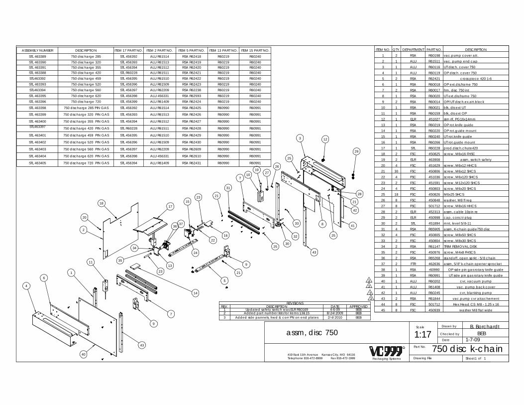
BEB2/4/2010Added side pannels, hwd & corr PN on end plates3BEB8/24/2009Added part number lists for items 13&152BEB4-6-09Updated safety switch was ELR R601691
APPROVEDDATEDESCRIPTIONREV.REVISIONS
ASSEMBLY NUMBER DESCRIPTION ITEM 17 PART NO. ITEM 2 PART NO. ITEM 5 PART NO. ITEM 13 PART NO. ITEM 15 PART NO.
STL 463389 750 discharge 285 STL 456392 ALU R61514 RSA R62418 R60219 R60240STL 463390 750 discharge 320 STL 456393 ALU R61513 RSA R62419 R60219 R60240STL 463391 750 discharge 355 STL 456394 ALU R61512 RSA R62420 R60219 R60240STL 463388 750 discharge 420 STL R60228 ALU R61511 RSA R62421 R60219 R60240STL463392 750 discharge 459 STL 456395 ALU R61510 RSA R62422 R60219 R60240STL 463393 750 discharge 520 STL 456396 ALU R61509 RSA R62423 R60219 R60240STL463394 750 discharge 560 STL 456397 ALU R62209 RSA R62238 R60219 R60240STL 463395 750 discharge 620 STL 456398 ALU 456331 RSA R62593 R60219 R60240STL 463396 750 discharge 720 STL 456399 ALU R61409 RSA R62424 R60219 R60240
STL 463398 750 discharge 285 PIN GAS STL 456392 ALU R61514 RSA R62425 R60990 R60991
STL 463399 750 discharge 320 PIN GAS STL 456393 ALU R61513 RSA R62426 R60990 R60991
STL 463400 750 discharge 355 PIN GAS STL 456394 ALU R61512 RSA R62427 R60990 R60991STL463397 750 discharge 420 PIN GAS STL R60228 ALU R61511 RSA R62428 R60990 R60991
STL 463401 750 discharge 459 PIN GAS STL 456395 ALU R61510 RSA R62429 R60990 R60991
STL 463402 750 discharge 520 PIN GAS STL 456396 ALU R61509 RSA R62430 R60990 R60991
STL 463403 750 discharge 560 PIN GAS STL 456397 ALU R62209 RSA R62609 R60990 R60991
STL 463404 750 discharge 620 PIN GAS STL 456398 ALU 456331 RSA R62610 R60990 R60991
STL 463405 750 discharge 720 PIN GAS STL 456394 ALU R61409 RSA R62431 R60990 R60991
BEB
Packaging Systems
R
Telephone 816-472-8999 Fax 816-472-1999419 East 11th Avenue Kansas City, MO 64116
Drawn by
Date
Checked by
Scale
Part No.
1:17750 disc k-chain
assm, disc 750
Drawing File ofSheet1 1
B. Borchardt
1-7-09
4
6
3
1
2
11
20
17
7
9
14
23
35
34
3637
2315
2216
21
31
7
1910 27
26
3 12
29
25
833
25
32
3025
28
21
21
5
913
24 43
42
18
41
43
40
33
3
ITEM NO. QTY. DEPARTMENT PART NO. DESCRIPTION1 2 RSA R60198 vac.pump cover att.2 1 ALU R61511 vac. pump end cap3 1 ALU R60116 UT disch. cover 7504 1 ALU R60119 OP disch. cover 7505 2 RSA R62421 cross piece 420 1-66 1 RSA R60018 OP ext.dis.frame 7507 2 RSA R60017 frm, disc 750 int8 1 RSA R60020 UT ext.dis.frame 7509 2 RSA R60014 OP/UT disch.ex.att.block
10 1 RSA R60021 blk, dis ext UT 11 1 RSA R60159 blk, dis ext OP12 1 ELR 451027 strn rlf, PG16x14mm13 1 RSA R60219 OP rot.knife guide14 1 RSA R60220 OP rot.guide mount15 1 RSA R60240 UT rot.knife guide16 1 RSA R60266 UT rot.guide mount17 1 STL R60228 prod.disch.chute42018 2 FSC 450825 screw, M6x16 FHSC19 2 ELR 463908 assm, switch safety20 4 FSC 451629 screw, M6x12 HHCS21 30 FSC 450806 screw, M6x12 SHCS22 4 FSC 451036 screw, M6x120 SHCS23 2 FSC 451591 screw, M12x120 SHCS24 4 FSC 450803 screw, M6x20 SHCS25 18 FSC 450826 M6x25 SHCS26 8 FSC 450848 washer, M8 fl reg 27 8 FSC 501712 screw, M8x16 HHCS28 2 ELR 452313 assm, cable 10pin re29 2 ELR 450998 cap, conctr plug30 2 STL 451894 mnt, level 5/8-1131 4 RSA R65905 assm, K-chain guide750 disc32 4 FSC 450805 screw, M8x50 SHCS33 2 FSC 450804 screw, M8x30 SHCS34 2 RSA R61147 TRIM REMOVAL DISK35 2 FSC 450976 screw, M4x8 FHSCS36 2 RSA R65268 standoff, open sprkt - 5/8 chain37 2 FTR 462636 assm, 5/8" k-chain opener sprocket38 1 RSA r60990 OP side pin gas rotary knife guide39 1 RSA R60991 UT side pin gas rotary knife guide40 1 ALU R60202 cvr, vacuum pump41 1 ALU R61408 vac. pump back cover42 1 ALU R60245 cvr, blanking pump43 2 RSA R61844 vac.pump cvr attachement44 8 FSC 501712 Hex Head CS M8 - 1.25 x 1645 8 FSC 450939 washer M8 flat wide

REVISIONSREV. DESCRIPTION DATE APPROVED
B. BorchardtBEB
Packaging Systems
R
Telephone 816-472-8999 Fax 816-472-1999419 East 11th Avenue Kansas City, MO 64116
Drawn by
Date
Checked by
Scale
Part No.
1:1ELR 463908
assm, switch safety
Drawing File 463908 ofSheet1 1
3-31-09
2 1
ITEM NO. QTY. DEPARTMENT PART NO. DESCRIPTION1 1 ELR 462475 switch, safety 2 no contacts2 1 ELR 462603 cable, M8 x 10M 4 pin

462636
Finish
63ofSheet11Packaging Systems
R
Telephone 816-472-8999 Fax 816-472-1999419 East 11th Avenue Kansas City, MO 64116
Drawn by
Date
Checked by
Scale B. SARSFIELD
Part No.> 3 > 3..6 ..6
±0,1 ±0,2 ±0,3 ±0,5 ±0,8 ±1,2±0,1 ±0,2 ±0,3 ±0,5 ±0,8
±0,1±1° ±30' ±20' ±10' ±5'±0,5±0,2
±2±1 ±4±2
AngleRadiusLength
DrawnDrawn (mm)Drawn (mm)
Tolerance (mm) Tolerance (mm) Tolerance (Degree and Minutes)
> 10 > 50 > 120 > 400..10 ..50 ..120 ..400
> 120> 30> 6> 0,5..400..120..30..3
±0,05 ±0,05 ±0,15
> 0,5..3
> 6..30
> 120> 30..400..120
> 1000 > 2000> 400..2000 ..4000..1000
NormalClose
X accuracyselection
Required accuracy
Standard Tolerance
X X X
X X
1:1
Drawing File
FTR 462636
assm, 5/8" k-chain opener sprocketSurface 10/8/08
REVISIONSREV. DESCRIPTION DATE APPROVED
1 Changed pin size was 3x6 now 3x12 12/6/2010 BEB
6
7
4
5
2
1
8
3
1
ITEM NO. QTY. DEPARTMENT PART NO. DESCRIPTION1 1 RSA R65495 sprkt, opnr-5/8"chain, sqz knife PR zip 2 2 FSC 452603 int. snap ring 47mm3 3 FBR 462634 Bearing, BALL K-chain4 1 RSA R65497 shaft, opener sprkt5 1 RSA R65498 ring, sprocket retainer6 1 FSC 462635 23mm external snap ring7 1 RSA R65496 ring, opener bevel8 1 FSC 460489 pin, dowel 3x12mm

Drawn by
Date
Checked by
Scale
TRM460216
assm, trim removal 1:5460216Part No.
Drawing File
S. WILLCOTT
ofSheet1Packaging Systems
R
Telephone 816-472-8999 Fax 816-472-1999419 East 11th Avenue Kansas City, MO 64116
1
REVISIONSREV. DESCRIPTION DATE APPROVED
1 ADDED RSA R65803 3/25/2009 BEB
30
42
33 19
18
17
20
34
23
231
4
41
3324
28
33
32
26 25
35
30
16
15
1
5
613
3
12
7
9 11
14
11
30
21
8
30
22
11
10
37
38
40
39
1
ITEM NO. QTY. DEPARTMENT PART NO. DESCRIPTION1 1 TRM 460356 frame2 1 RSA R63978 insert3 1 RSA R64014 endblock4 1 RSA R63979 flange, trim removal5 1 TRM 460357 wldmnt, arm lh6 1 TRM 460358 wldmnt, arm rh7 2 RSA R63976 pin, dancer8 2 RSA R63977 shaft, pinchwheel9 2 RSA R63860 pinchwheel
10 12 ORR 460210 oring, 1.1"X.21" bun11 6 FSC 460136 ring, retn ext .5"12 2 FSC 450874 nut, M8 hex reg13 2 FSC 460362 plunger, spring14 1 RSA R63975 shaft, pivot15 1 ELR 452576_1 dc motor 1/15hp16 1 RSA R64015 bracket, motor mtg17 1 RSA R63855 arbor18 1 TRM 460361 assm, drivewheel19 1 RSA R63856 washer20 1 FSC 460434 washer, belleville21 1 TRM 460360 hinge, piano22 1 TRM 460359 wldmnt, cover23 1 ELR 460137 dc motor control assembly24 1 RSA R63980 standoff25 1 RSA R63972 brkt, steering shaft26 1 RSA R63973 shaft, steering27 1 RSA R63865 nutbar28 4 FSC 452209 screw, M4x8 PHSL 29 5 FSC 450869 screw, M4x8 SHCS30 11 FSC 451293 M5x12 FHSCS31 2 FSC 450836 M5x25 FHSCS32 1 FSC 450825 screw, M6x16 FHSC33 5 FSC 450806 screw, M6x12 SHCS34 2 FSC 455613 screw, M6x8 SHSS CP35 4 FSC 460433 screw, 10-32 x .75 SHCS36 2 FSC 460954 screw, M6x16 HHCS37 2 FSC 451067 washer, M6 fl reg38 4 ORR 455433 oring, 20x3mm buna39 4 RSA R65321 spcr, trim revolve40 4 FSC 451294 screw, M4x25 SHCS41 1 RSA R61087 vertical support mount42 1 RSA R65803 sleeve, trm unwnd shft

1
2
ITEM NO. QTY. DEPARTMENT PART NO. DESCRIPTION1 1 RSA R64011 sleeve, drivewheel2 1 RSA R64012 cap, end
Part No.
Packaging Systems
R
Telephone 816-472-8999 Fax 816-472-1999419 East 11th Avenue Kansas City, MO 64116
Drawn by
Date
Revisions:
Checked by
Scale Karl Marek
1:5460361
Drawing File of
assm, drivewheel
Sheet1460361TRM
1
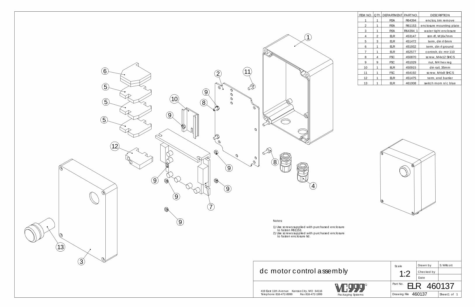
Sheet1Packaging Systems
R
Telephone 816-472-8999 Fax 816-472-1999419 East 11th Avenue Kansas City, MO 64116
Drawn by
Date
Checked by
Scale S. Willcott
Part No.
1:2ELR 460137
dc motor control assembly
Drawing File 460137 of 1
7
1
4
8
112
10
9
9
9
12
5
5
6
13
3
9
9
9
89
to fasten R61153.1) Use screws supplied with purchased enclosure
2) Use screws supplied with purchased enclosure to fasten enclosure lid.
Notes:
5
ITEM NO. QTY. DEPARTMENT PART NO. DESCRIPTION1 1 RSA R64394 enclos, trm remove2 1 RSA R61153 enclosure mounting plate3 1 RSA R64394_1 water tight enclosure4 2 ELR 453147 strn rlf, M16x7mm5 3 ELR 451472 term, din rl 6mm6 1 ELR 451932 term, din rl ground7 1 ELR 452577 controlr, dc mtr 1108 4 FSC 450870 screw, M4x12 SHCS9 9 FSC 451029 nut, M4 hex reg
10 1 ELR 450915 din rail, 35mm11 1 FSC 454192 screw, M4x8 SHCS12 1 ELR 451475 term, end barrier13 1 ELR 461008 switch mom n/c blue

1
B. BorchardtBEB
Packaging Systems
R
Telephone 816-472-8999 Fax 816-472-1999419 East 11th Avenue Kansas City, MO 64116
Drawn by
Date
Sheet1
Checked by
Scale
Part No.ARS1:4assm water cooler
466208Drawing File 466208 of
11-23-10
REVISIONS
REV. DESCRIPTION DATE APPROVED
14
2
3
ITEM NO. QTY. DEPARTMENT PART NO. DESCRIPTION1 1 ARS 466074 water cooler2 2 PRS 450993 tube, 1/2" clear3 2 PRS 453842 fitting 3/8 bar x 1/2 NPT4 4 FSC 450114 clamp, worm 1/2" hose
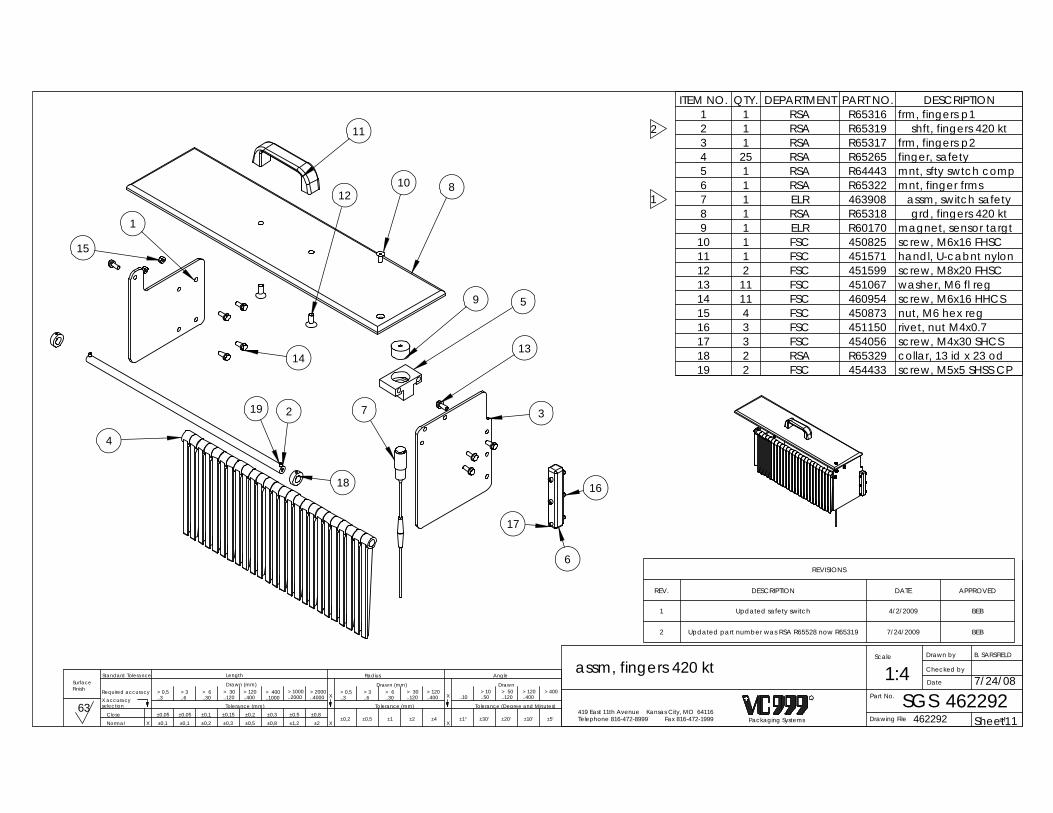
1
2
REVISIONS
REV. DESCRIPTION DATE APPROVED
1 Updated safety switch 4/2/2009 BEB
2 Updated part number was RSA R65528 now R65319 7/24/2009 BEB
Finish
63ofSheet11Packaging Systems
R
Telephone 816-472-8999 Fax 816-472-1999419 East 11th Avenue Kansas City, MO 64116
Drawn by
Date
Checked by
Scale B. SARSFIELD
Part No.> 3 > 3..6 ..6
±0,1 ±0,2 ±0,3 ±0,5 ±0,8 ±1,2±0,1 ±0,2 ±0,3 ±0,5 ±0,8
±0,1±1° ±30' ±20' ±10' ±5'±0,5±0,2
±2±1 ±4±2
AngleRadiusLength
DrawnDrawn (mm)Drawn (mm)
Tolerance (mm) Tolerance (mm) Tolerance (Degree and Minutes)
> 10 > 50 > 120 > 400..10 ..50 ..120 ..400
> 120> 30> 6> 0,5..400..120..30..3
±0,05 ±0,05 ±0,15
> 0,5..3
> 6..30
> 120> 30..400..120
> 1000 > 2000> 400..2000 ..4000..1000
NormalClose
X accuracyselection
Required accuracy
Standard Tolerance
X X X
X X
1:4SGS
462292462292
assm, fingers 420 kt
Drawing File
Surface 7/24/08
1
9
11
1012
8
15
5
13
3
16
17
6
2
18
19
4
14
7
ITEM NO. QTY. DEPARTMENT PART NO. DESCRIPTION1 1 RSA R65316 frm, fingers p12 1 RSA R65319 shft, fingers 420 kt3 1 RSA R65317 frm, fingers p24 25 RSA R65265 finger, safety5 1 RSA R64443 mnt, sfty swtch comp6 1 RSA R65322 mnt, finger frms7 1 ELR 463908 assm, switch safety8 1 RSA R65318 grd, fingers 420 kt9 1 ELR R60170 magnet, sensor targt
10 1 FSC 450825 screw, M6x16 FHSC11 1 FSC 451571 handl, U-cabnt nylon12 2 FSC 451599 screw, M8x20 FHSC13 11 FSC 451067 washer, M6 fl reg14 11 FSC 460954 screw, M6x16 HHCS15 4 FSC 450873 nut, M6 hex reg16 3 FSC 451150 rivet, nut M4x0.717 3 FSC 454056 screw, M4x30 SHCS18 2 RSA R65329 collar, 13 id x 23 od19 2 FSC 454433 screw, M5x5 SHSS CP

of
LTC
B. BorchardtBEB
Packaging Systems
R
Telephone 816-472-8999 Fax 816-472-1999419 East 11th Avenue Kansas City, MO 64116
Drawn by
Date
Checked by
Part No.
452487 Sheet1Drawing File
Scale
1
1:3rotary knife assembly
4524875-19-09
2
1
ITEM NO. QTY. DEPARTMENT PART NO. DESCRIPTION1 1 LTC R60481 assm, OP rtry knf mnt2 1 LTC 452220 rotary knife motor assembly
Note:Shaft assembly and blades shown as reference only.
REVISIONS
REV. DESCRIPTION DATE APPROVED

Scale J. Romfo
LTCPart No.
assm, OP rtry knf mnt 1:1
R60481 ofSheet1Packaging Systems
R
Telephone 816-472-8999 Fax 816-472-1999419 East 11th Avenue Kansas City, MO 64116
Drawn by
Date
Checked by
R60481Drawing File 1
ITEM NO. 459/QTY. Dept./Part No. DESCRIPTION
1 1 RSAR60481 OP rotary knife mount
2 1 RSA R60488 idler collar3 1 FBR450849 bearing roller 9104PP
4 2 FSC451055 M6x80 SHCS5 1 FSC450947 M8 ball plunger
6 1 ELR 451453 plug, tub 1.00 dia
REVISIONS
REV. DESCRIPTION DATE APPROVED
1 Del snap ring; added plug & plunger 2/11/2010 BEB
3
1
4
1
2
1

ITEM NO. 459/QTY. Dept./Part No. DESCRIPTION
1 1 ELR451217 rotary knife motor Siemen
2 1 RSAR60209 utility side rotary knife mount
3 1 LTCR60487 drive motor extension
4 4 FSC451031 screw, M5x20 SHCS
5 2 FSC450804 screw, M8x30 SHCS
6 1 ELR 453147 strn rlf, M16x7mm
REVISIONSREV. DESCRIPTION DATE APPROVED
1 Add item 6 3/8/2006 BSY
Packaging Systems
R
Telephone 816-472-8999 Fax 816-472-1999419 East 11th Avenue Kansas City, MO 64116
Drawn by
Date
Checked by
Scale J. Romfo
Part No.
1:2LTC 452220
rotary knife motor assembly
Drawing File 452220 ofSheet1 1
5
14
3
2
6
1

Packaging SystemsTelephone 816-472-8999 Fax 816-472-1999419 East 11th Avenue Kansas City, MO 64116
Drawn by
Date
Revisions:
Checked by
Scale J. Romfo
Part No.
2:1LTC R60488
idler collar
Drawing File R60488 ofSheet1 1
2
1
ITEM NO. QTY. DEPARTMENT PART NO. DESCRIPTION LOCATION MATERIAL MATERIAL P/N
1 1 RSA R60488 idler collar X04D22 stainless ALU450852
2 1 FSC 450947 M8 ball plunger X06I23 stainless N/A

ITEM NO. 459/QTY. Dept./Part No. DESCRIPTION
1 1 RSAR60148 rotary knife blade hub
2 1 FSC450952 screw, M8x10 SHSS CP
3 3 FSC 450951 screw, M5x8 PHSL
4 1 LTCR60149 rotary knife blade
Packaging Systems
R
Telephone 816-472-8999 Fax 816-472-1999419 East 11th Avenue Kansas City, MO 64116
Drawn by
Date
Checked by
Scale J. Romfo
Part No.
1:1LTC R60148
rotary knife blade hub
Drawing File R60148 ofSheet1 1
23
1
4
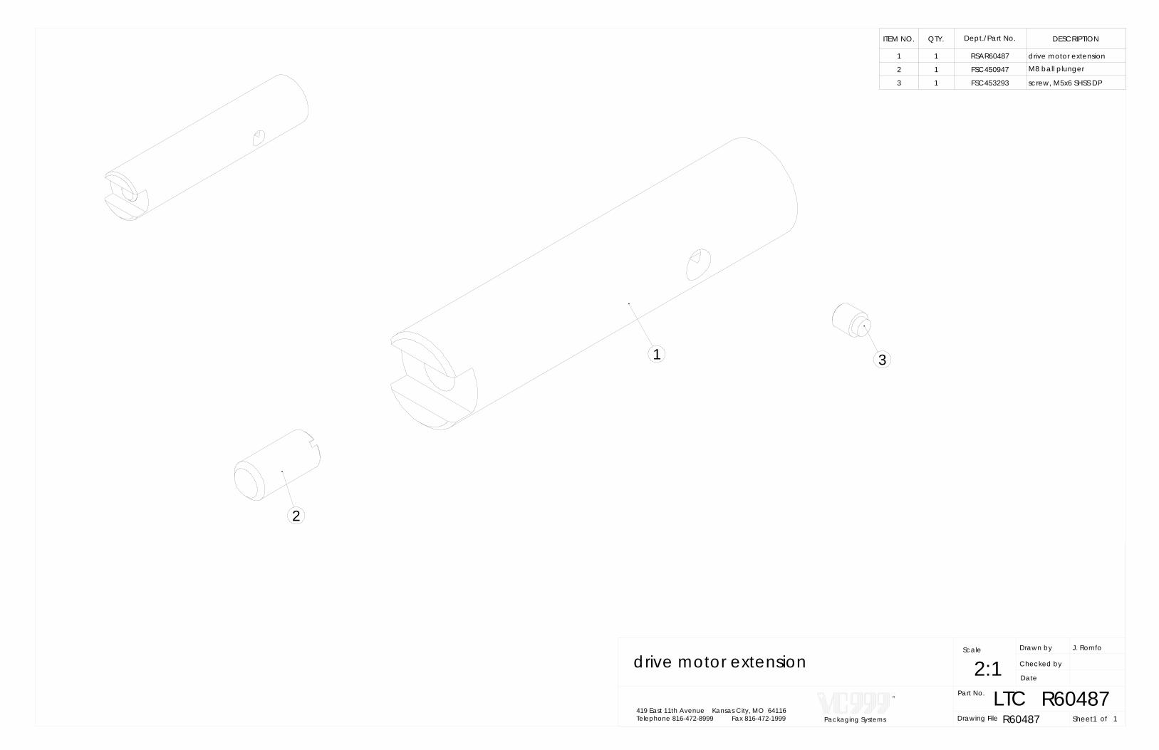
1
2
3
ITEM NO. QTY. Dept./Part No. DESCRIPTION
1 1 RSAR60487 drive motor extension
2 1 FSC450947 M8 ball plunger
3 1 FSC453293 screw, M5x6 SHSS DP
Packaging Systems
R
Telephone 816-472-8999 Fax 816-472-1999419 East 11th Avenue Kansas City, MO 64116
Drawn by
Date
Checked by
Scale J. Romfo
Part No.
2:1LTC R60487
drive motor extension
Drawing File R60487 ofSheet1 1

2
1
4
3
ITEM NO. QTY. DEPARTMENT PART NO. DESCRIPTION
1 1 RSA R60485 rotary knife shaft 4202 2 FSC 451070 compression spring3 2 RSA R60486 shaft collar
4 4 FSC 450869 M4x6 SHCS
Packaging SystemsTelephone 816-472-8999 Fax 816-472-1999419 East 11th Avenue Kansas City, MO 64116
Drawn by
Date
Revisions:
Checked by
Scale J. Romfo
Part No.
1:2LTC 451961
rotary knife quick release 420
Drawing File 451961 ofSheet1 1

Drawing FilePackaging Systems
R
Telephone 816-472-8999 Fax 816-472-1999419 East 11th Avenue Kansas City, MO 64116
Drawn by
Date
Checked by
Scale M. Vogler
CCTofSheet1
Part No. 4578631
assm, cross cut 420 1:2.5
457863
tube clear 6mm x 4mmPRS451071120
fit, 6x8 STPRS 458443119
washer, M4 fl reg
ITEM NO. 420/QTY. Dept./Part No. DESCRIPTION
1 1 PRS 457734 cyl, 12x(420) crs ct
2 1 RSA R63031 mnt, cross cut blade3 2 RSA R63030 mnt, cross cut cyl
4 2 PRS 450979 fit, 6xM5 905 2 RSA R63032 ramp, cross ct bld
6 1 RSA R63029 pin, cross cut pivot
7 1 FSC 457616 washer, M6 fl nyl
8 2 RSAR60167 cross cut slider
9 4 FSC450801 M6x30 SHCS
10 2 FSC 453247 screw, M5x12 SHCS11 2 FSC450848 washer, M8 fl reg
12 2 FSC 455922 screw, M8x40 SHCS13 1 FSC451536 sprng, tors 2x10 R
14 1 CCT 452306 assm, knife 15 1 FSC451066 nut, M6 hex reg lk
16 1 FSC450976 screw, M4x8 FHSCS
17 2 FSC452209 screw, M4x8 PHSL 18 2 FSC 451032
REVISIONSREV. DESCRIPTION DATE APPROVED
1 Added hose and fitting corrected PT 2/24/2011 BEB
1
5
15
95
8
410
11
12
1
3
716
2
6
1713
14
18
9
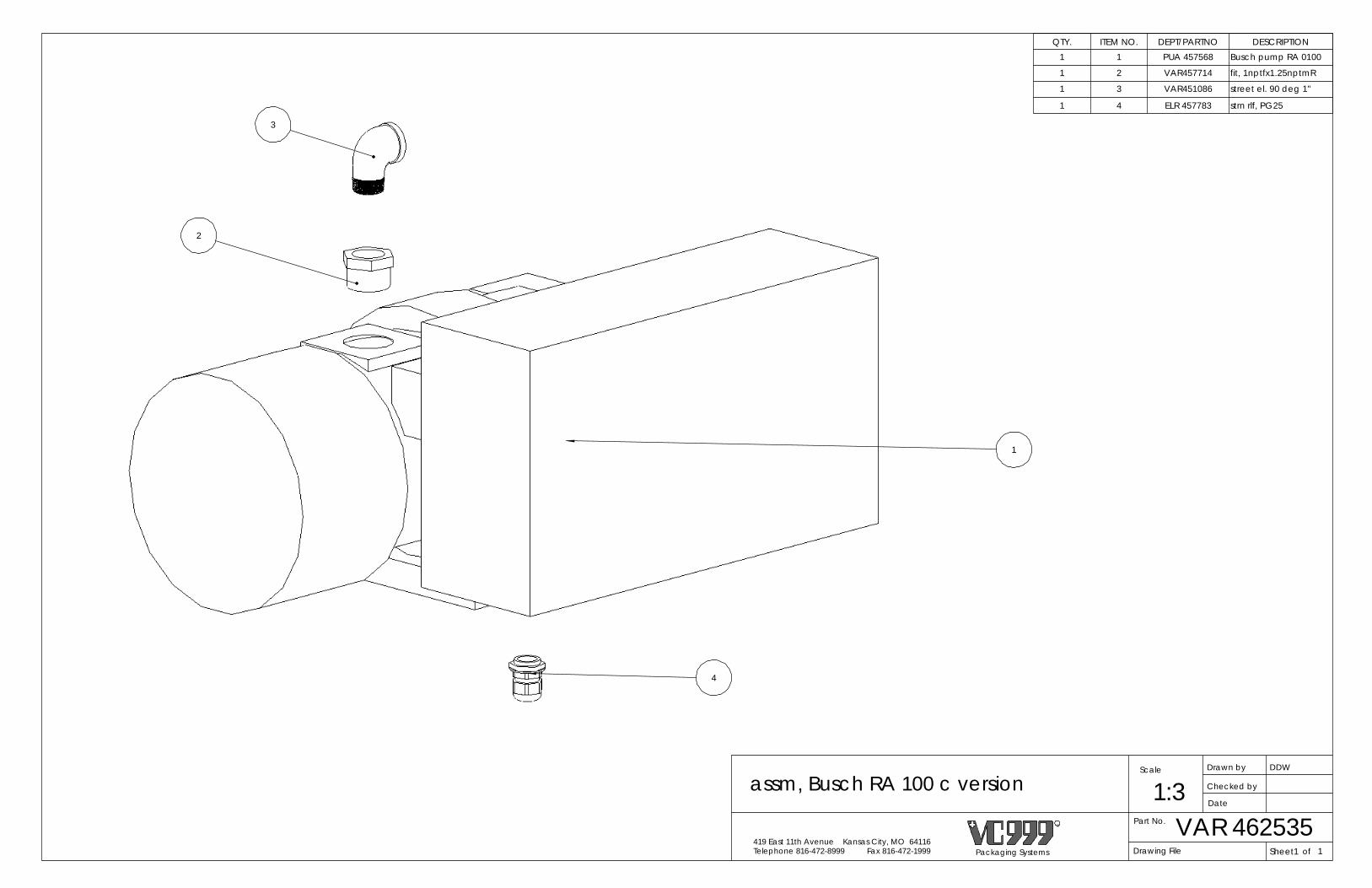
ofSheet1Packaging Systems
R
Telephone 816-472-8999 Fax 816-472-1999419 East 11th Avenue Kansas City, MO 64116
Drawn by
Date
Checked by
Scale DDW
Part No.
1:3VAR 462535
assm, Busch RA 100 c version
Drawing File 1
QTY. ITEM NO. DEPT/PARTNO DESCRIPTION1 1 PUA 457568 Busch pump RA 0100
1 2 VAR457714 fit, 1nptfx1.25nptmR
1 3 VAR451086 street el. 90 deg 1"
1 4 ELR 457783 strn rlf, PG25
2
1
3
4

PLCSheet1Packaging Systems
R
Telephone 816-472-8999 Fax 816-472-1999419 East 11th Avenue Kansas City, MO 64116
Drawn by
Date
Checked by
Scale
assm, cd statnry 420 1:4
454895
Part No. 454895
R. Swaney
Drawing File of 1
REVISIONS
REV. DESCRIPTION DATE APPROVED
1 Converted head to an assembly 8/17/2009 BEB
4
15
12
11
13
12 89
13
73
10
6
5
148 1
7
27
ITEM NO. QTY. DEPARTMENT PART NO. DESCRIPTION1 1 RSA R60271 code date slider 2 1 RSA R60269 stat.cd cross355/4203 1 RSA R61920 platnt, cd stat 4204 1 RSA R61918 brkt, code date OP5 1 RSA R61919 brkt, code date UT6 3 FSC 451586 screw, M8x20 SHCS7 8 FSC 450803 screw, M6x20 SHCS8 6 FSC 450848 washer, M8 fl reg 9 4 FSC 451229 screw, M8x35 HHCS
10 1 PLA 454357 neoprene, 2"x3/16"x25ft11 1 ALU 451187 brkt, code date UT12 6 FSC 451189 nut, M8 sq reg13 2 FSC 451188 plug, tub 41x86 rec14 2 FSC 450972 M8x25 adj. lever15 1 PLC 464526 assm, code dater head

3
1
2
ITEM NO. QTY. DEPARTMENT PART NO. DESCRIPTION1 1 PLC 460928 coder, CCI2 1 PRS 450902 tube, 4mm clear3 1 PRS 451159 fit, 4xM5 SS
Note: Fitting PRS 451159 is used on both ends of the tubing but one is supplied with the code dater head so only one is inclueded in this assembly.
BEB
Packaging Systems
R
Telephone 816-472-8999 Fax 816-472-1999419 East 11th Avenue Kansas City, MO 64116
Drawn by
Date
Checked by
Scale B. Borchardt
Part No.
1:2PLC
assm, code dater head
464526464526Drawing File ofSheet1 1
8-17-09
1
1
REVISIONS
REV. DESCRIPTION DATE APPROVED
1 Added note and removed fitting. 11/22/2010 BEB

Items 7-10 (Vacuum Valve O-Ring Replacement Kit)
3
2
11
4 5
1213
6
1
14
8
9
10
7
ITEM NO. QTY. DEPARTMENT PART NO. DESCRIPTION1 1 RSA R62108 valv, part body2 1 RSA R62107 valv, part body cap3 1 RSA R62106 valv, part exust prt4 1 RSA R62150 pistn, vac vent5 1 FSC 455399 sprng, comp vac vent6 1 FSC 455398 sprng, comp vac valv7 1 ORR 455433 oring, 20x3mm buna8 1 ORR 455354 seal, v-ring pst 60m9 1 ORR 455353 seal, v-ring pst 40m
10 1 ORR 455387 oring, 63.09x3.53mm11 4 FSC 451036 screw, M6x120 SHCS12 2 FSC 454237 screw, M6x75 SHCS13 1 VAR 455435 assm, vnt valv 3/414 1 RSA R62149 assm, piston vac valve

SECTION 10 - DIE ASSEMBLY DRAWINGS

1
7
8
6
7
?
11
10
9
16
15
14
7
3
2
4
13
7
12
5
Bill of Material
ITEM NO. Dept. Part Num. QTY. DESCRIPTION1 DFT 245010 1 420/240 form die top2 DHP 245020 1 420/240 heater plate3 DHP 245020_1 1 420/240 heater back plate4 DHP 245024 1 420/240 F. heat plate (pyramid)5 DFB 245031 1 420/240 form die bottom6 DFD 245230 1 420/240 2:1 divider set7 DFD 245902 6 dwall MD 240/19.058 DFR 155051 2 420/240 2:1 radius plate9 DFD 155043 1 420/240 2:2 divider set10 DFD 155046 2 420/240 2:1 divider wall across machine11 DFR 155054 4 420/240 2:2 radius plate12 DFD 245221 1 420/240 3:1 135 divider set13 DFR 245223 3 radius plate 420/240 3:1 19.0514 DFD 245642 1 420/240 3:2 divider set15 DFD 245643 3 420/240 3:2 divider wall across machine16 DFR 245650 6 420/240 3:2 radius plate
This is an Electronically Generated Document, DO NOT SCALE
All Dimensions in mm
Die 245 Forming Caribbean BroilersDepartment
.5x.
R
TolerancesUnless Specified
Mat'l Num.
Part No.
1/2.01.1.3
ANG.XXX.XX.X
SPECIFICATIONS
419 East 11th AvenueKansas City, MO 64116
Telephone 816-472-8999 Fax 816-472-1999
JC
J.Cornett9/12/2011
245DIES
Sheet
Checked byDesigner
Drawn by
011
THIS PRINT CONTAINS CONFIDENTIAL INFORMATION WHICH IS THE PROPERTY OF VC999 BY ACCEPTING THIS
INFORMATION THE BORROWER AGREES THAT IT WILL NOT BE USED FOR ANY PURPOSE OTHER THAN THAT FOR WHICH
IT IS LOANED.
SCALE
DATE (M-D-Y)
Description
SHEET
OFB
Finish:
THIRD ANGLE PROJECTION
245forming_Caribbean BroilersFile Name
1:6
R
Packaging Systems, Inc.

1
10
9
12
7
13
11
6
8
14
5
3
4
2
Bill of MaterialITEM NO. Dept. Part Num. QTY. DESCRIPTION
1 DST 245061 1 bladder s. die top 420.2402 DPP 245070 1 pusher plate 420.2403 DHP 245020 1 420/240 heater plate4 DHP 245020_1 1 420/240 heater back plate5 DSP 245071 1 420/240 total seal6 DSB 245081 1 420/240 seal die bottom7 DSS 245234 1 420/240 2:1 seal frame8 DSS 155094 1 420/240 2:2 seal frame9 DSS 245226 1 420/240 3:1 19.05 seal frame10 PLA 245126 1 gasket, 420/240 3:111 DSS 245690 1 420/240 3:2 seal frame12 PLA 155101 1 gasket, 420/240 2:113 PLA 155106 1 gasket, 420/240 3:214 PLA 155104 1 gasket, 420/240 2:2
This is an Electronically Generated Document, DO NOT SCALE
All Dimensions in mm
Die 245 Sealing Caribbean BroilersDepartment
.5x.
R
TolerancesUnless Specified
Mat'l Num.
Part No.
1/2.01.1.3
ANG.XXX.XX.X
SPECIFICATIONS
419 East 11th AvenueKansas City, MO 64116
Telephone 816-472-8999 Fax 816-472-1999
JC
J.Cornett9/12/2011
245DIES
Sheet
Checked byDesigner
Drawn by
011
THIS PRINT CONTAINS CONFIDENTIAL INFORMATION WHICH IS THE PROPERTY OF VC999 BY ACCEPTING THIS
INFORMATION THE BORROWER AGREES THAT IT WILL NOT BE USED FOR ANY PURPOSE OTHER THAN THAT FOR WHICH
IT IS LOANED.
SCALE
DATE (M-D-Y)
Description
SHEET
OFB
Finish:
THIRD ANGLE PROJECTION
245sealing_Caribbean BroilersFile Name
1:6
R
Packaging Systems, Inc.

43
37
35
36
34
38
41
40
39
42
13
33
2912
11
26
25
2
3
18
17
1415
16
24
1
2322
27
4
19
30
31
32
see heater plate assemblyfor more details
28
ITEM NO.
QTY.Departme
ntPART NUMBER DESCRIPTION
1 1 DFT Ref. Die Components form die top
2 1 DHP Ref. Die Components heater plate
3 1 DHP Ref. Die Components heater back plate
4 10 FSC 451580 insrt, M6 keen
5 1 ELR 451589Thermocouple for heat plates
6 2 FSC 450895 screw, M3x6 PHSL
7 1 ELR 451535 wire, 14ga, thhn, grn/yel
8 1 ELR 453645 term, ring 14-16 AWG
9 1 FSC 450869 screw, M4x6 SHCS
10 7 ELR Ref. Mach. Components Calrod heater
11 18 FSC 450825 screw, M6x16 FHSC
12 6 FSC 451825 M6x50 FHSCS
13 1 DHP Ref. Die Components F heat plate
14 6 FSC 450896 screw, M12x110 HHCS
15 6 FSC 450897 washer, M12 fl reg
16 6 FSC 455612 M6x80 FHSCS
17 11 RSA R60455 spacer, 10.5mm
18 11 FSC 450803 screw, M6x20 SHCS
19 1 ELR 451968 reducer, plug PG21
20 1 ELR 451969 plug, 7 pin insert male
21 5 ELR 451972 Pin Contact
22 4 FSC 451572 insrt, M12 keen
23 4 RSA R60471 Die Handle
24 1 VAR 453013 1" NPT flush plug
25 1 DCA R60411 die top electr.cover
26 8 FSC 451293 M5x12 FHSCS
27 10 FSC 452182 plug, 1/8 NPT
28 4 FSC 452698 7/8" dia ball SS
29 4 FAA 509103 ring, retn int 42mm
30 4 FSC 452697 die roller compression spring
31 4 FSC 450878 screw, M8x10 SHCS
32 4 RSA r61138 socket backup plate
33 4 RSA R61245 42mm die roller socket
34 1 DFB Ref. Die Components form die bottom
35 2 FSC 451575 insrt, M10 keen
36 1 VAR 450932 fit, 1barx1npt h brb
37 8 PRS 454243 fit, 8x3/8bspp
38 1 DFD Ref. Die Components div. set
39 1 DFD Ref. Die Components d. wall md
40 2 DFD Ref. Die Components d. wall
41 7 FSC 450806 screw, M6x12 SHCS
42 4 DFR Ref. Die Components radius plate
43 4 DFI Ref. Die Components hdr insert
Sheet1Packaging Systems
R
Telephone 816-472-8999 Fax 816-472-1999419 East 11th Avenue Kansas City, MO 64116
Drawn by
Date
Checked by
Scale DDW
Part No.
1:7Forming Assembly
Drawing File of 1

APPROVEDDATEDESCRIPTIONREV.REVISIONS
ITEM NO. Department PART NUMBER DESCRIPTION MATERIAL
1 DHP Die specific heater plate 6061-T6
2 DHP Die specific heater back plate 6061-T6
3 FSC 451580 insrt, M6 keen stainless
4 ELR 451589 Thermocouple for heat plates stainless
5 FSC 450895 screw, M3x6 PHSL stainless
6 ELR 451535 wire, 14ga, thhn, grn/yel ---
7 ELR 453645 term, ring 14-16 AWG ---
8 FSC 450869 screw, M4x6 SHCS stainless
9 ELR Die specific Calrod heater element
10 FSC 450825 screw, M6x16 FHSC stainless
11 FSC 451825 M6x50 FHSCS stainless
12 ELR 451871 wire sleeve Nomex weave
6
10
2
11
3
4
5
1
9
87
12
R
Packaging Systems of
Checked by
Date
DDWDrawn byScale
1:3Part No.
Drawing File
Heater Plate Assembly
Sheet1419 East 11th Avenue Kansas City, MO 64116Telephone 816-472-8999 Fax 816-472-1999 1

3
2
1
10
8
5
9
4
7
6
Scale DDW
Part No.
1:3.5Seal Die Bottom Assembly
Drawing File ofSheet1Packaging Systems
R
Telephone 816-472-8999 Fax 816-472-1999419 East 11th Avenue Kansas City, MO 64116
Drawn by
Date
Checked by
1
REVISIONS
REV. DESCRIPTION DATE APPROVED
ITEM NO.
QTY.Department
PART NUMBER DESCRIPTION
1 1 DSB Ref. Die Components seal die bottom
2 1 DSS Ref. Die Components hdr seal frame
3 1 PLA Ref. Mach. Components seal gasket
4 4 FSC 450952 screw, M8x10 SHSS CP
5 4 RSA R63274 hardstop
6 8 FSC 450826 screw, M6x25 SHCS
7 4 FSC 450947 M8 ball plunger
8 2 FSC 451575 insrt, M10 keen
9 8 FSC 450938 6mmx20mm long pin
10 1 VAR 450932 fit, 1barx1npt h brb

ITEM NO.
QTY.Departm
entPART NUMBER DESCRIPTION
1 1 DST Ref. Die Components bladder s. die top
2 1 DST Ref. Die Components OP roller mount 3 1 DST Ref. Die Components UT roller mount 4 6 FSC 450897 washer, M12 fl reg
5 6 FSC 455371 screw, M12x140 HHCS6 4 RSA R62448 plug, bladder7 4 VAR 453013 1" NPT flush plug8 2 FSC 455359 plug, 1/2 npt flush9 10 FSC 452182 plug, 1/8 NPT
10 4 FSC 450948 screw, M5x16 FHSCS11 4 FSC 451572 insrt, M12 keen12 4 RSA R60471 Die Handle
13 1 ELR 451968 reducer, plug PG21
14 1 ELR 451969 plug, 7 pin insert male
15 5 ELR 451972 Pin Contact16 1 ELR 452584 eurostrip, 2pl17 1 ELR 452596 eurostrip, 3pl 14-6
18 32 FSC 451580 insrt, M6 keen 19 4 PRS Ref. Mach. Components bladder
20 1 DCA R60411 die top electr.cover
21 8 FSC 451293 M5x12 FHSCS
22 4 FSC 452698 7/8" dia ball SS23 4 FSC 452697 die roller compression spring
24 4 FSC 450878 screw, M8x10 SHCS25 4 RSA r61138 socket backup plate
26 4 RSA R61245 42mm die roller socket
27 4 FAA 509103 ring, retn int 42mm
28 1 DPP Ref. Die Components pusher plate
29 20 FSC 450803 screw, M6x20 SHCS
30 20 FSC 455361 sprng, comp 21od dt
31 20 FBR 455360 bearing, bushing 6x16x20 dt
32 1 DHP Ref. Die Components heater plate
33 1 DHP Ref. Die Components heater back plate
34 1 ELR 451589Thermocouple for heat plates
35 2 FSC 450895 screw, M3x6 PHSL 36 1 ELR 451535 wire, 14ga, thhn, grn/yel
37 1 ELR 453645 term, ring 14-16 AWG
38 1 FSC 450869 screw, M4x6 SHCS
39 7 ELR Ref. Mach. Components Calrod heater
40 24 FSC 450825 screw, M6x16 FHSC
41 6 FSC 451825 M6x50 FHSCS
42 1 DSP Ref. Die Components perimeter seal
43 4 DSP Ref. Die Components isolator
44 2 FSC 451415 thick hard fiber washer
45 8 FSC 453679 M6x10 FHSCS SP
5
4
6
2
10
7
12
11
20
21
23
24
25
26
27
22
1
19
2818
30
31
29
33
40
32
42
43
45
41
18
39
40
8
44
9
3
13
see heater plate assemblyfor more detail
1
1
NOTES1) PARTS USED FOR LARGE DIES ONLY
ofSheet1Packaging Systems
R
Telephone 816-472-8999 Fax 816-472-1999419 East 11th Avenue Kansas City, MO 64116
Drawn by
Date
Checked by
Scale DDW
Part No.
1:6Seal Die Top Assembly
Drawing File 1

Part No.
1:1DLM
die mount assem. - tall
462052462052Drawing File ofSheet1Packaging Systems
R
Telephone 816-472-8999 Fax 816-472-1999419 East 11th Avenue Kansas City, MO 64116
Drawn by
Date
Checked by
Scale B. SARSFIELD
1
7/30/08
REVISIONSREV. DESCRIPTION DATE APPROVED
1 ADDED LOCK WASHER 459853 12-8-08 BEB2 SCREW WAS M10X 80 NOW M10X90 1/26/2009 BEB
3 Added note removed ORR 456850 from BOM 3/26/2010 BEB
24
1
5
62
7
6
ADHESIVE - 2 PLCS.
2
7
5
supplied with Seal die bottom
AFFIX WITH THREAD LOCK
2
3
ASEMBLY NOTE:USE M14X1.5 KEY INSERT(PART # FSC451575)FOR BOLTS.
ORR 456850 Shown for reference only3
ITEM NO. QTY. DEPARTMENT PART NO. DESCRIPTION1 1 RSA R65164 die mnt block - tall2 1 RSA R62760 stud, die botm lk3 1 FBR 456537 brg, BUSH 12x15x7 fl4 1 FSC 453463 screw, SH 12x12xM105 2 FSC 453494 M10 X 90 HHCS6 2 FSC 451034 M10 flat washer7 2 FSC 451575 insrt, M10 keen

1
2
3
1
assm, discharge rail with insertDrawn by
of
Checked by
Sheet1
Part No.
DDW
Packaging Systems
R
Telephone 816-472-8999 Fax 816-472-1999
1:2
419 East 11th Avenue Kansas City, MO 64116Drawing File
Date
Scale
-
QTY. ITEM NO. DEPT/PARTNO DESCRIPTION MATERIAL MATERIAL_P_N
1 1 see die list discharge supt rail 6061-T6 ALU451054
1 2 RSA R65198 dis.rail rot knf insrt 6061-T6 ALU451054
2 3 FSC450877 screw, M6x16 SHCS stainless N/A

NOTES

NOTES