Embed Size (px)
Citation preview
Global Partner. Local Friend.
LVSLow Voltage Switchgears
The complete solutionfor line and load side
SUPER AE Air Circuit Breakers /// WSS Moulded-CaseCircuit Breakers /// MS-N Magnetic Contactors ///Mitsubishi Electric Europe B.V. /// FA - European Business Group /// Gothaer Straße 8 /// D-40880 Ratingen /// Germany
Tel.: +49(0)2102-4860 /// Fax: +49(0)2102-4861120 /// [email protected] /// www.mitsubishi-automation.comSpecifications subject to change /// Art. no. 216798-A /// 12.2008
All trademarks and copyrights acknowledged.
EUROPEAN BRANCHES
GERMANYMITSUBISHI ELECTRIC EUROPE B.V.Gothaer Straße 8D-40880 RatingenPhone: +49 (0)2102 / 486-0
CZECH REP.MITSUBISHI ELECTRIC EUROPE B.V.-org.sl.Radlická 714/113aCZ-158 00 Praha 5Phone: +420 - 251 551 470
FRANCEMITSUBISHI ELECTRIC EUROPE B.V.25, Boulevard des BouvetsF-92741 Nanterre CedexPhone: +33 (0)1 / 55 68 55 68
ITALYMITSUBISHI ELECTRIC EUROPE B.V.Viale Colleoni 7I-20041 Agrate Brianza (MB)Phone: +39 039 / 60 53 1
POLANDMITSUBISHI ELECTRIC EUROPE B.V.Krakowska 50PL-32-083 BalicePhone: +48 (0)12 / 630 47 00
RUSSIAMITSUBISHI ELECTRIC EUROPE B.V.52, bld. 3 Kosmodamianskaya nab 8 floorRU-115054 МoscowPhone: +7 495 721-2070
SPAINMITSUBISHI ELECTRIC EUROPE B.V.Carretera de Rubí 76-80E-08190 Sant Cugat del Vallés (Barcelona)Phone: 902 131121 // +34 935653131
UKMITSUBISHI ELECTRIC EUROPE B.V.Travellers LaneUK-Hatfield, Herts. AL10 8XBPhone: +44 (0)1707 / 27 61 00
EUROPEAN REPRESENTATIVES
BELARUSTECHNIKONOktyabrskaya 19, Off. 705BY-220030 MinskPhone: +375 (0)17 / 210 46 26
BELGIUMKoning & Hartman b.v.Woluwelaan 31BE-1800 VilvoordePhone: +32 (0)2 / 257 02 40
BOSNIA AND HERZEG.INEA RBT d.o.o.Aleja Lipa 56BA-71000 SarajevoPhone: +387 (0)33 / 921 164
CZECH REPUBLICAutoCont CS s.r.o.Technologická 374/6CZ-708 00 Ostrava-PustkovecPhone: +420 595 691 150
CGREECEANTONIOS DREPANIAS S.A.52, Arkadias Str.GR-12132 Peristeri, AthensPhone: +30 210 / 578 1599
GREECEKALAMARAKIS-SAPOUNAS S.A.Ionias & Neromilou Str.GR-13671 Cham. Achames AthensPhone: +30 (0)2102 / 406000
GREECEUTECO5, Mavrogenous Str.GR-18542 PiraeusPhone: +30 211 / 1206 900
HUNGARYMELTRADE Kft.Fertő utca 14.HU-1107 BudapestPhone: +36 (0)1 / 431-9726
KAZAKHSTANTOO KazpromavtomatikaUl. Zhambyla 28KAZ-100017 KaragandaPhone: +7 7212 / 50 10 00
LITHUANIARIFAS UABTinklu g. 29ALT-5300 PanevezysPhone: +370 (0)45 / 582 728
MOLDOVAINTEHSIS SRLbld. Traian 23/1MD-2060 KishinevPhone: +373 (0)22 / 66 4242
NETHERLANDSImtech M & O B.V.Sluisjesdijk 155NL-3087 AG RotterdamPhone: +31 (0)10 / 487 19 11
NORWAYSCANELEC ASLeirvikasen 43BNO-5179 GodvikPhone: +47 (0)55 / 50 60 00
PORTUGALFonseca S.A.R. João Francisco do Casal 87/89PT - 3801-997 Aveiro, EsgueiraPhone: +351 (0)234 / 303 900
ROMANIASirius Trad. & Serv. srlAleea Lacul Morii Nr. 3RO-060841 Bucuresti, Sector 6Phone: +40 (0)21 / 430 40 06
SLOVAKIASIMAP s.r.o.Jána Derku 1671SK-911 01 TrencínPhone: +421 (0)32 743 04 72
SLOVAKIAPROCONT,spol.sr.o.PrešovKúpelná 1/ASK-080 01 PrešovPhone: +421 (0)51 7580 611
SLOVENIAINEA RBT d.o.o.Stegne 11SI-1000 LjubljanaPhone: +386 (0)1 / 513 8116
SWEDENEuro Energy Components ABJärnvägsgatan 36SE-434 24 KungsbackaPhone: +46 (0)300 / 69 00 40
SWITZERLANDTRIELEC AGMühlentalstr. 136CH-8201 SchaffhausenPhone: +41 (0)52 / 632 102 0
TURKEYGTSBayraktar Bulvari Nutuk Sok. No:5TR-34775 Yukarı İSTANBULPhone: +90 (0)216 526 39 90
UKRAINECSC Automation Ltd.4-B, M. Raskovoyi St.UA-02660 KievPhone: +380 (0)44 / 494 33 55
UKRAINESystemgroup2 M. Krivonosa St.UA-03680 KievPhone: +380 (0)44 / 490 92 29
ISRAELGINO Industries Ltd.26, Ophir streetIL-32235 HaifaPhone: +972 (0)4 / 867 06 56
LEBANONCEG INTERNATIONALCebaco Center/Block A Autostrade DORALebanon - BeirutPhone: +961 (0)1 / 240 430
SOUTH AFRICACBI Ltd.Private Bag 2016ZA-1600 IsandoPhone: + 27 (0)11 / 977 0770
Version check
Low Voltage Switchgears /// Moulded-Case Circuit Breakers /// Magnetic Contactors /// Automation solutions /// Automation solutions /// Automation solutions /// Automation
Breakthrough technology
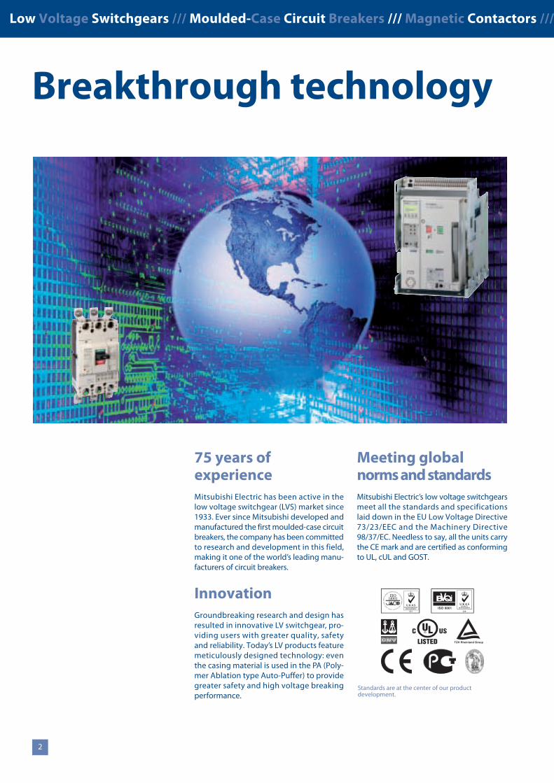
75 years ofexperienceMitsubishi Electric has been active in thelow voltage switchgear (LVS) market since1933. Ever since Mitsubishi developed andmanufactured the first moulded-case circuitbreakers, the company has been committedto research and development in this field,making it one of the world’s leading manu-facturers of circuit breakers.
InnovationGroundbreaking research and design hasresulted in innovative LV switchgear, pro-viding users with greater quality, safetyand reliability. Today’s LV products featuremeticulously designed technology: eventhe casing material is used in the PA (Poly-mer Ablation type Auto-Puffer) to providegreater safety and high voltage breakingperformance.
Meeting globalnorms and standardsMitsubishi Electric’s low voltage switchgearsmeet all the standards and specificationslaid down in the EU Low Voltage Directive73/23/EEC and the Machinery Directive98/37/EC. Needless to say, all the units carrythe CE mark and are certified as conformingto UL, cUL and GOST.
2
Standards are at the center of our productdevelopment.
Mitsubishi offers a wide range of automation equipment from PLCs and HMIs to CNC and EDM machines
A name to trustSince its beginnings in 1870, some45 companies use the Mitsubishi name,covering a spectrum of finance, commerceand industry.
The Mitsubishi brand name is recognizedaround the world as a symbol of premiumquality.
Mitsubishi Electric Corporation representsspace development, transportation, semicon-ductors, energy systems, communicationsand information processing, audio visualequipment, home electronics, building andenergy management and automation sys-tems, and has 237 factories and laboratoriesworldwide in over 121 countries.
Robots
Motion control and servos
Inverters
HMI and GOTs
Micro PLCs
EDM machines
CNCcontrollers
Laser machines
LV circuit protection
Modular PLCs
A world ofautomation solutions
This is why you can rely on a Mitsubishiautomation solution – because we know firsthand about the need for reliable, efficient,easy-to-use automation and control.
As one of the world’s leading companieswith a global turnover of 3.4 trillion Yen(approximately $30.8 billion), employingover 100 000 people, Mitsubishi Electrichas the resource and the commitment todeliver the ultimate in service and supportas well as the best products.
Low Voltage Switchgears /// Moulded-Case Circuit Breakers /// Magnetic Contactors /// Low Voltage Switchgears /// Moulded-Case Circuit Breakers /// Magnetic Contactors ///
Breakthrough technology
75 years ofexperienceMitsubishi Electric has been active in thelow voltage switchgear (LVS) market since1933. Ever since Mitsubishi developed andmanufactured the first moulded-case circuitbreakers, the company has been committedto research and development in this field,making it one of the world’s leading manu-facturers of circuit breakers.
InnovationGroundbreaking research and design hasresulted in innovative LV switchgear, pro-viding users with greater quality, safetyand reliability. Today’s LV products featuremeticulously designed technology: eventhe casing material is used in the PA (Poly-mer Ablation type Auto-Puffer) to providegreater safety and high voltage breakingperformance.
Meeting globalnorms and standardsMitsubishi Electric’s low voltage switchgearsmeet all the standards and specificationslaid down in the EU Low Voltage Directive73/23/EEC and the Machinery Directive98/37/EC. Needless to say, all the units carrythe CE mark and are certified as conformingto UL, cUL and GOST.
Contents
32
The six stoutly reasons 4 – 5
A complete solution for line and load side 6 – 7
SUPER AE – Air Circuit Breakers 8 – 9
WSS – Moulded-Case Circuit Breakers 10 – 11
MS-N – Magnetic Contactors 12 – 13
A wide field of applications 14
Standards are at the center of our productdevelopment.
Six stoutly reasons /// Six stoutly reasons /// Six stoutly reasons /// Six stoutly reasons /// Six stoutly reasons /// Six stoutly reasons /// Six stoutly reasons /// Six stoutly reasons ///
Six stoutly reasons for Mitsubishi LVS
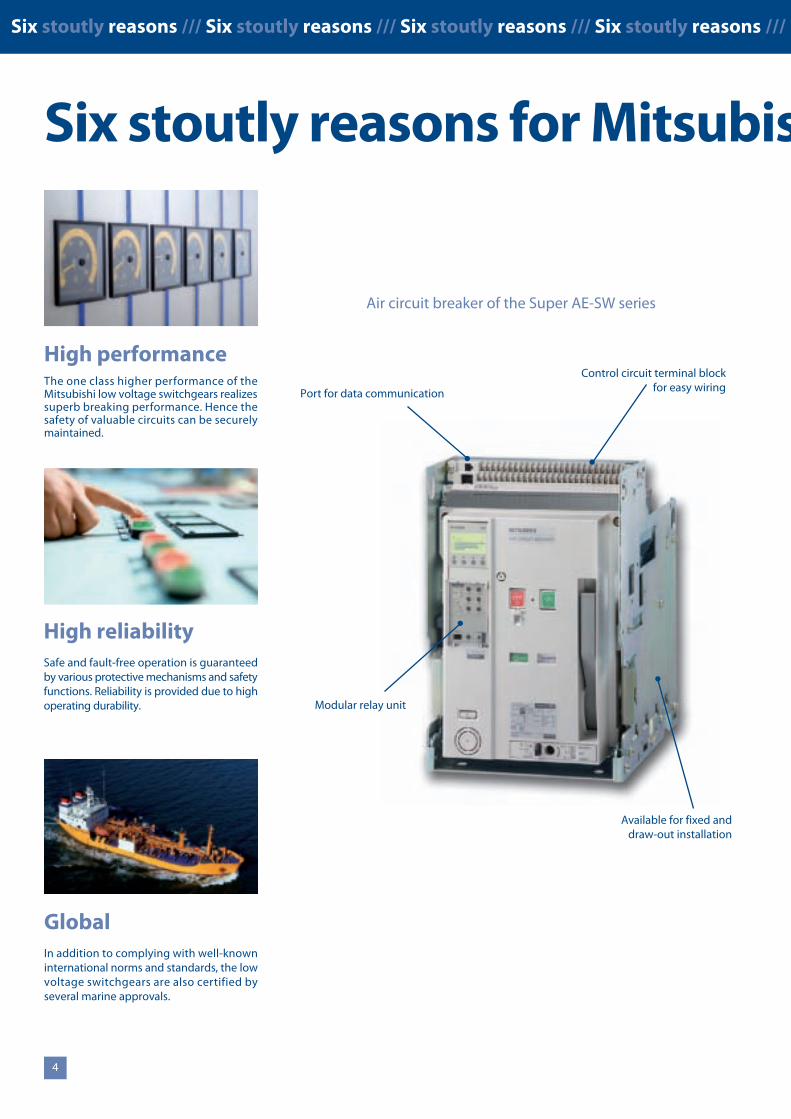
High reliabilitySafe and fault-free operation is guaranteedby various protective mechanisms and safetyfunctions. Reliability is provided due to highoperating durability.
High performanceThe one class higher performance of theMitsubishi low voltage switchgears realizessuperb breaking performance. Hence thesafety of valuable circuits can be securelymaintained.
GlobalIn addition to complying with well-knowninternational norms and standards, the lowvoltage switchgears are also certified byseveral marine approvals.
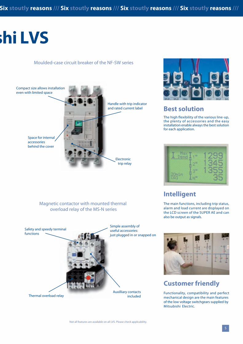
Best solutionThe high flexibility of the various line-up,the plenty of accessories and the easyinstallation enable always the best solutionfor each application.
54
IntelligentThe main functions, including trip status,alarm and load current are displayed onthe LCD screen of the SUPER AE and canalso be output as signals.
Customer friendlyFunctionality, compatibility and perfectmechanical design are the main featuresof the low voltage switchgears supplied byMitsubishi Electric.
Not all features are available on all LVS. Please check applicability.
Control circuit terminal blockfor easy wiring
Modular relay unit
Port for data communication
Available for fixed anddraw-out installation
Compact size allows installationeven with limited space
Electronictrip relay
Space for internalaccessoriesbehind the cover
Auxilliary contactsincludedThermal overload relay
Simple assembly ofuseful accessories:just plugged in or snapped on
Air circuit breaker of the Super AE-SW series
Moulded-case circuit breaker of the NF-SW series
Magnetic contactor with mounted thermaloverload relay of the MS-N series
Safety and speedy terminalfunctions
Handle with trip indicatorand rated current label
Six stoutly reasons /// Six stoutly reasons /// Six stoutly reasons /// Six stoutly reasons /// Six stoutly reasons /// Six stoutly reasons /// Six stoutly reasons /// Six stoutly reasons ///
Six stoutly reasons for Mitsubishi LVS
High reliabilitySafe and fault-free operation is guaranteedby various protective mechanisms and safetyfunctions. Reliability is provided due to highoperating durability.
High performanceThe one class higher performance of theMitsubishi low voltage switchgears realizessuperb breaking performance. Hence thesafety of valuable circuits can be securelymaintained.
GlobalIn addition to complying with well-knowninternational norms and standards, the lowvoltage switchgears are also certified byseveral marine approvals.
Best solutionThe high flexibility of the various line-up,the plenty of accessories and the easyinstallation enable always the best solutionfor each application.
54
IntelligentThe main functions, including trip status,alarm and load current are displayed onthe LCD screen of the SUPER AE and canalso be output as signals.
Customer friendlyFunctionality, compatibility and perfectmechanical design are the main featuresof the low voltage switchgears supplied byMitsubishi Electric.
Not all features are available on all LVS. Please check applicability.
Control circuit terminal blockfor easy wiring
Modular relay unit
Port for data communication
Available for fixed anddraw-out installation
Compact size allows installationeven with limited space
Electronictrip relay
Space for internalaccessoriesbehind the cover
Auxilliary contactsincludedThermal overload relay
Simple assembly ofuseful accessories:just plugged in or snapped on
Air circuit breaker of the Super AE-SW series
Moulded-case circuit breaker of the NF-SW series
Magnetic contactor with mounted thermaloverload relay of the MS-N series
Safety and speedy terminalfunctions
Handle with trip indicatorand rated current label
A complete solution for line and load side
A complete solution for line and load side /// A complete solution for line and load side /// A complete solution for line and load side /// A complete solution for line and load side ///
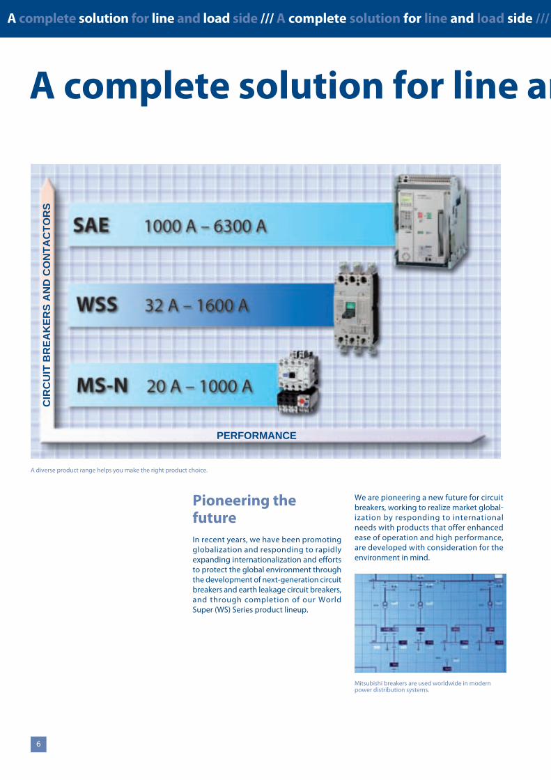
We are pioneering a new future for circuitbreakers, working to realize market global-ization by responding to internationalneeds with products that offer enhancedease of operation and high performance,are developed with consideration for theenvironment in mind.
Pioneering thefutureIn recent years, we have been promotingglobalization and responding to rapidlyexpanding internationalization and effortsto protect the global environment throughthe development of next-generation circuitbreakers and earth leakage circuit breakers,and through completion of our WorldSuper (WS) Series product lineup.
6 7
A diverse product range helps you make the right product choice.
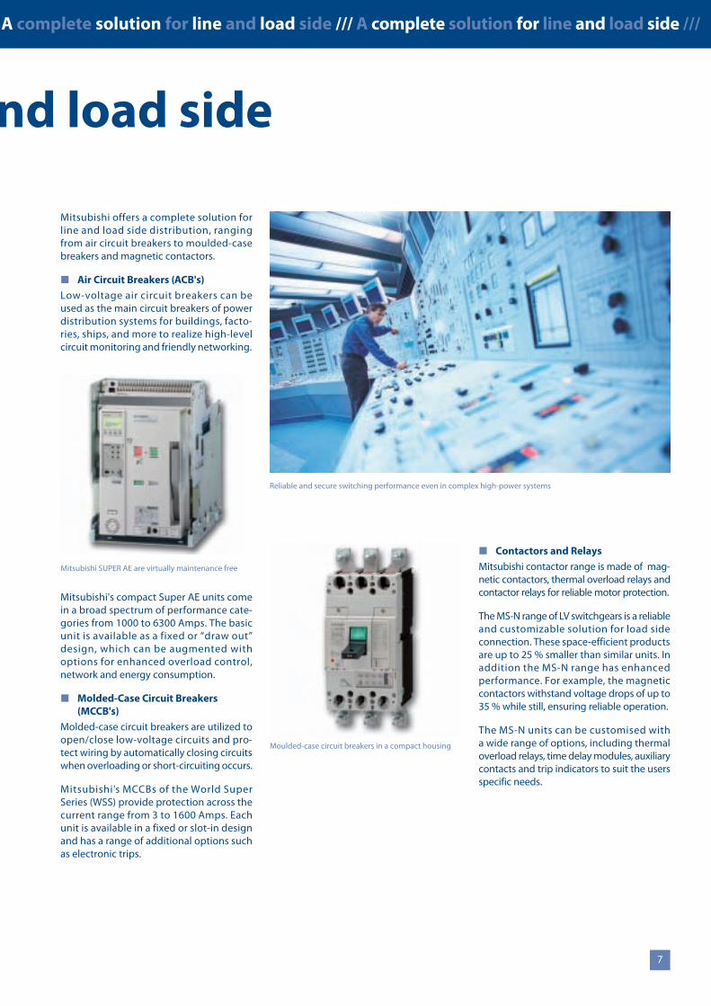
Reliable and secure switching performance even in complex high-power systems
Mitsubishi offers a complete solution forline and load side distribution, rangingfrom air circuit breakers to moulded-casebreakers and magnetic contactors.
Air Circuit Breakers (ACB's)
Low-voltage air circuit breakers can beused as the main circuit breakers of powerdistribution systems for buildings, facto-ries, ships, and more to realize high-levelcircuit monitoring and friendly networking.
Mitsubishi's compact Super AE units comein a broad spectrum of performance cate-gories from 1000 to 6300 Amps. The basicunit is available as a fixed or “draw out”design, which can be augmented withoptions for enhanced overload control,network and energy consumption.
Molded-Case Circuit Breakers(MCCB's)
Molded-case circuit breakers are utilized toopen/close low-voltage circuits and pro-tect wiring by automatically closing circuitswhen overloading or short-circuiting occurs.
Mitsubishi’s MCCBs of the World SuperSeries (WSS) provide protection across thecurrent range from 3 to 1600 Amps. Eachunit is available in a fixed or slot-in designand has a range of additional options suchas electronic trips.
Contactors and Relays
Mitsubishi contactor range is made of mag-netic contactors, thermal overload relays andcontactor relays for reliable motor protection.
The MS-N range of LV switchgears is a reliableand customizable solution for load sideconnection. These space-efficient productsare up to 25 % smaller than similar units. Inaddition the MS-N range has enhancedperformance. For example, the magneticcontactors withstand voltage drops of up to35 % while still, ensuring reliable operation.
The MS-N units can be customised witha wide range of options, including thermaloverload relays, time delay modules, auxiliarycontacts and trip indicators to suit the usersspecific needs.
Moulded-case circuit breakers in a compact housing
Mitsubishi SUPER AE are virtually maintenance freePERFORMANCE
CIR
CU
ITB
RE
AK
ER
SA
ND
CO
NT
AC
TO
RS
Mitsubishi breakers are used worldwide in modernpower distribution systems.
A complete solution for line and load side
A complete solution for line and load side /// A complete solution for line and load side /// A complete solution for line and load side /// A complete solution for line and load side ///
We are pioneering a new future for circuitbreakers, working to realize market global-ization by responding to internationalneeds with products that offer enhancedease of operation and high performance,are developed with consideration for theenvironment in mind.
Pioneering thefutureIn recent years, we have been promotingglobalization and responding to rapidlyexpanding internationalization and effortsto protect the global environment throughthe development of next-generation circuitbreakers and earth leakage circuit breakers,and through completion of our WorldSuper (WS) Series product lineup.
6 7
A diverse product range helps you make the right product choice.
Reliable and secure switching performance even in complex high-power systems
Mitsubishi offers a complete solution forline and load side distribution, rangingfrom air circuit breakers to moulded-casebreakers and magnetic contactors.
Air Circuit Breakers (ACB's)
Low-voltage air circuit breakers can beused as the main circuit breakers of powerdistribution systems for buildings, facto-ries, ships, and more to realize high-levelcircuit monitoring and friendly networking.
Mitsubishi's compact Super AE units comein a broad spectrum of performance cate-gories from 1000 to 6300 Amps. The basicunit is available as a fixed or “draw out”design, which can be augmented withoptions for enhanced overload control,network and energy consumption.
Molded-Case Circuit Breakers(MCCB's)
Molded-case circuit breakers are utilized toopen/close low-voltage circuits and pro-tect wiring by automatically closing circuitswhen overloading or short-circuiting occurs.
Mitsubishi’s MCCBs of the World SuperSeries (WSS) provide protection across thecurrent range from 3 to 1600 Amps. Eachunit is available in a fixed or slot-in designand has a range of additional options suchas electronic trips.
Contactors and Relays
Mitsubishi contactor range is made of mag-netic contactors, thermal overload relays andcontactor relays for reliable motor protection.
The MS-N range of LV switchgears is a reliableand customizable solution for load sideconnection. These space-efficient productsare up to 25 % smaller than similar units. Inaddition the MS-N range has enhancedperformance. For example, the magneticcontactors withstand voltage drops of up to35 % while still, ensuring reliable operation.
The MS-N units can be customised witha wide range of options, including thermaloverload relays, time delay modules, auxiliarycontacts and trip indicators to suit the usersspecific needs.
Moulded-case circuit breakers in a compact housing
Mitsubishi SUPER AE are virtually maintenance freePERFORMANCE
CIR
CU
ITB
RE
AK
ER
SA
ND
CO
NT
AC
TO
RS
Mitsubishi breakers are used worldwide in modernpower distribution systems.
8 9
Super AE –Air Circuit Breakers
SUPER AE /// Air Circuit Breakers /// SUPER AE /// Air Circuit Breakers /// SUPER AE /// Air Circuit Breakers /// SUPER AE /// Air Circuit Breakers /// SUPER AE /// Air Circuit Breakers ///
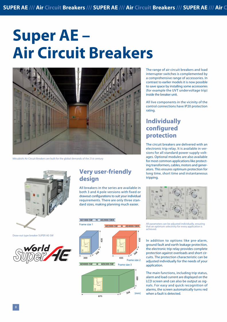
Very user-friendlydesignAll breakers in the series are available inboth 3 and 4 pole versions with fixed ordrawout configurations to suit your individualrequirements. There are only three stan-dard sizes, making planning much easier.
Broad performancerangeThe growing demand for power naturallyincreases the levels of short circuit currentsin power distribution systems. The SUPERAE series breakers deliver excellent protec-tion against thermal and mechanical dam-age. The rated surge withstand capability(Uimp) is 12 kV. With a short circuit breakingcapacity of 65 – 85 kA they cover the greatmajority of applications, providing veryhigh-quality protection for your systems.
The small number of components and highproduction standards ensure a long servicelife. The breakers of the SUPER AE series arevirtually maintenance-free.
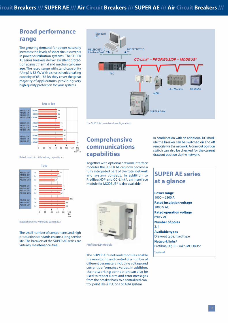
ComprehensivecommunicationscapabilitiesTogether with optional network interfacemodules the SUPER AE can now become afully integrated part of the total networkand system concept. In addition toProfibus/DP and CC-Link®, an interfacemodule for MODBUS® is also available.
The SUPER AE's network modules enablethe monitoring and control of a number ofdifferent parameters including voltage andcurrent performance values. In addition,the networking connection can also beused to report alarm and error messagesfrom the breaker back to a centralized con-trol point like a PLC or a SCADA system.
In combination with an additional I/O mod-ule the breaker can be switched on and offremotely via the network. A drawout positionswitch can also be checked for the currentdrawout position via the network.
The SUPER AE in network configurations
StandardPC
MELSECNET/10
PLC
CC-Link® – PROFIBUS/DP – MODBUS®
SUPER AE-SW
MDU
ECO Monitor ME96NSR
MELSECNET/10Interface Card
SUPER AE seriesat a glance
Power range1000 – 6300 A
Rated insulation voltage1000 V AC
Rated operation voltage690 V AC
Number of poles3, 4
Available typesDrawout type, fixed type
Network links*Profibus/DP, CC-Link®, MODBUS®
*optional
65AE1000-SWAE1250-SWAE1600-SWAE2000-SWA
690 V AC
600 V AC
~ 500 V AC
65
85
85
85
65
Icu = Ics
690 V AC
600 V AC
~ 500 V AC
6040200(kA)
Icu = Ics
80 100 120 140
AE2000-SWAE2500-SWAE3200-SWAE4000-SWA
AE4000-SWAE5000-SWAE6300-SW
690 V AC
600 V AC
~ 500 V AC
75
75
130
65AE1000-SWAE1250-SWAE1600-SWAE2000-SWA
1 s
2 s
3 s
60
100
85
Icw
1 s
2 s
3 s
6040200(kA)Icw
80 100
AE2000-SWAE2500-SWAE3200-SWAE4000-SWA
AE4000-SWAE5000-SWAE6300-SW
1 s
2 s
3 s
75
75
85
50
65
Rated short time withstand current Icw
Rated short circuit breaking capacity Ics
The range of air circuit breakers and loadinterrupter switches is complemented bya comprehensive range of accessories. Incontrast to earlier models it is now possibleto save space by installing some accessories(for example the UVT undervoltage trip)inside the breaker unit.
All live components in the vicinity of thecontrol connections have IP20 protectionrating.
IndividuallyconfiguredprotectionThe circuit breakers are delivered with anelectronic trip relay. It is available in ver-sions for all standard power supply volt-ages. Optional modules are also availablefor most common applications like protect-ing transformers, cables, motors and gener-ators. This ensures optimum protection forlong time, short time and instantaneoustripping.
In addition to options like pre-alarm,ground fault and earth leakage protection,the electronic trip relay provides completeprotection against overloads and short cir-cuits. The protection characteristic can beadjusted individually for the needs of yourapplication.
The main functions, including trip status,alarm and load current are displayed on theLCD screen and can also be output as sig-nals. For easy and quick recognition ofalarms, the screen automatically turns redwhen a fault is detected.
300
430
368
430
368
435
AE1000-SW AE2000-SWA
AE2000-SW AE4000-SWA
AE4000-SW AE6300-SW
480
368
875
Frame size 1
Profibus/DP module
Mitsubishi Air Circuit Breakers are built for the global demands of the 21st century
All parameters can be adjusted individually, ensuringthat an optimum selectivity for every application isachieved.
Frame size 3
Frame size 2
[mm]
Draw-out type breaker SUPER AE-SW
8 9
Super AE –Air Circuit Breakers
SUPER AE /// Air Circuit Breakers /// SUPER AE /// Air Circuit Breakers /// SUPER AE /// Air Circuit Breakers /// SUPER AE /// Air Circuit Breakers /// SUPER AE /// Air Circuit Breakers ///
Very user-friendlydesignAll breakers in the series are available inboth 3 and 4 pole versions with fixed ordrawout configurations to suit your individualrequirements. There are only three stan-dard sizes, making planning much easier.
Broad performancerangeThe growing demand for power naturallyincreases the levels of short circuit currentsin power distribution systems. The SUPERAE series breakers deliver excellent protec-tion against thermal and mechanical dam-age. The rated surge withstand capability(Uimp) is 12 kV. With a short circuit breakingcapacity of 65 – 85 kA they cover the greatmajority of applications, providing veryhigh-quality protection for your systems.
The small number of components and highproduction standards ensure a long servicelife. The breakers of the SUPER AE series arevirtually maintenance-free.
ComprehensivecommunicationscapabilitiesTogether with optional network interfacemodules the SUPER AE can now become afully integrated part of the total networkand system concept. In addition toProfibus/DP and CC-Link®, an interfacemodule for MODBUS® is also available.
The SUPER AE's network modules enablethe monitoring and control of a number ofdifferent parameters including voltage andcurrent performance values. In addition,the networking connection can also beused to report alarm and error messagesfrom the breaker back to a centralized con-trol point like a PLC or a SCADA system.
In combination with an additional I/O mod-ule the breaker can be switched on and offremotely via the network. A drawout positionswitch can also be checked for the currentdrawout position via the network.
The SUPER AE in network configurations
StandardPC
MELSECNET/10
PLC
CC-Link® – PROFIBUS/DP – MODBUS®
SUPER AE-SW
MDU
ECO Monitor ME96NSR
MELSECNET/10Interface Card
SUPER AE seriesat a glance
Power range1000 – 6300 A
Rated insulation voltage1000 V AC
Rated operation voltage690 V AC
Number of poles3, 4
Available typesDrawout type, fixed type
Network links*Profibus/DP, CC-Link®, MODBUS®
*optional
65AE1000-SWAE1250-SWAE1600-SWAE2000-SWA
690 V AC
600 V AC
~ 500 V AC
65
85
85
85
65
Icu = Ics
690 V AC
600 V AC
~ 500 V AC
6040200(kA)
Icu = Ics
80 100 120 140
AE2000-SWAE2500-SWAE3200-SWAE4000-SWA
AE4000-SWAE5000-SWAE6300-SW
690 V AC
600 V AC
~ 500 V AC
75
75
130
65AE1000-SWAE1250-SWAE1600-SWAE2000-SWA
1 s
2 s
3 s
60
100
85
Icw
1 s
2 s
3 s
6040200(kA)Icw
80 100
AE2000-SWAE2500-SWAE3200-SWAE4000-SWA
AE4000-SWAE5000-SWAE6300-SW
1 s
2 s
3 s
75
75
85
50
65
Rated short time withstand current Icw
Rated short circuit breaking capacity Ics
The range of air circuit breakers and loadinterrupter switches is complemented bya comprehensive range of accessories. Incontrast to earlier models it is now possibleto save space by installing some accessories(for example the UVT undervoltage trip)inside the breaker unit.
All live components in the vicinity of thecontrol connections have IP20 protectionrating.
IndividuallyconfiguredprotectionThe circuit breakers are delivered with anelectronic trip relay. It is available in ver-sions for all standard power supply volt-ages. Optional modules are also availablefor most common applications like protect-ing transformers, cables, motors and gener-ators. This ensures optimum protection forlong time, short time and instantaneoustripping.
In addition to options like pre-alarm,ground fault and earth leakage protection,the electronic trip relay provides completeprotection against overloads and short cir-cuits. The protection characteristic can beadjusted individually for the needs of yourapplication.
The main functions, including trip status,alarm and load current are displayed on theLCD screen and can also be output as sig-nals. For easy and quick recognition ofalarms, the screen automatically turns redwhen a fault is detected.
300
430
368
430
368
435
AE1000-SW AE2000-SWA
AE2000-SW AE4000-SWA
AE4000-SW AE6300-SW
480
368
875
Frame size 1
Profibus/DP module
Mitsubishi Air Circuit Breakers are built for the global demands of the 21st century
All parameters can be adjusted individually, ensuringthat an optimum selectivity for every application isachieved.
Frame size 3
Frame size 2
[mm]
Draw-out type breaker SUPER AE-SW
11
WSS /// Moulded-Case Circuit Breakers /// WSS /// Moulded-Case Circuit Breakers /// WSS /// Moulded-Case Circuit Breakers /// WSS /// Moulded-Case Circuit Breakers /// WSS ///
10
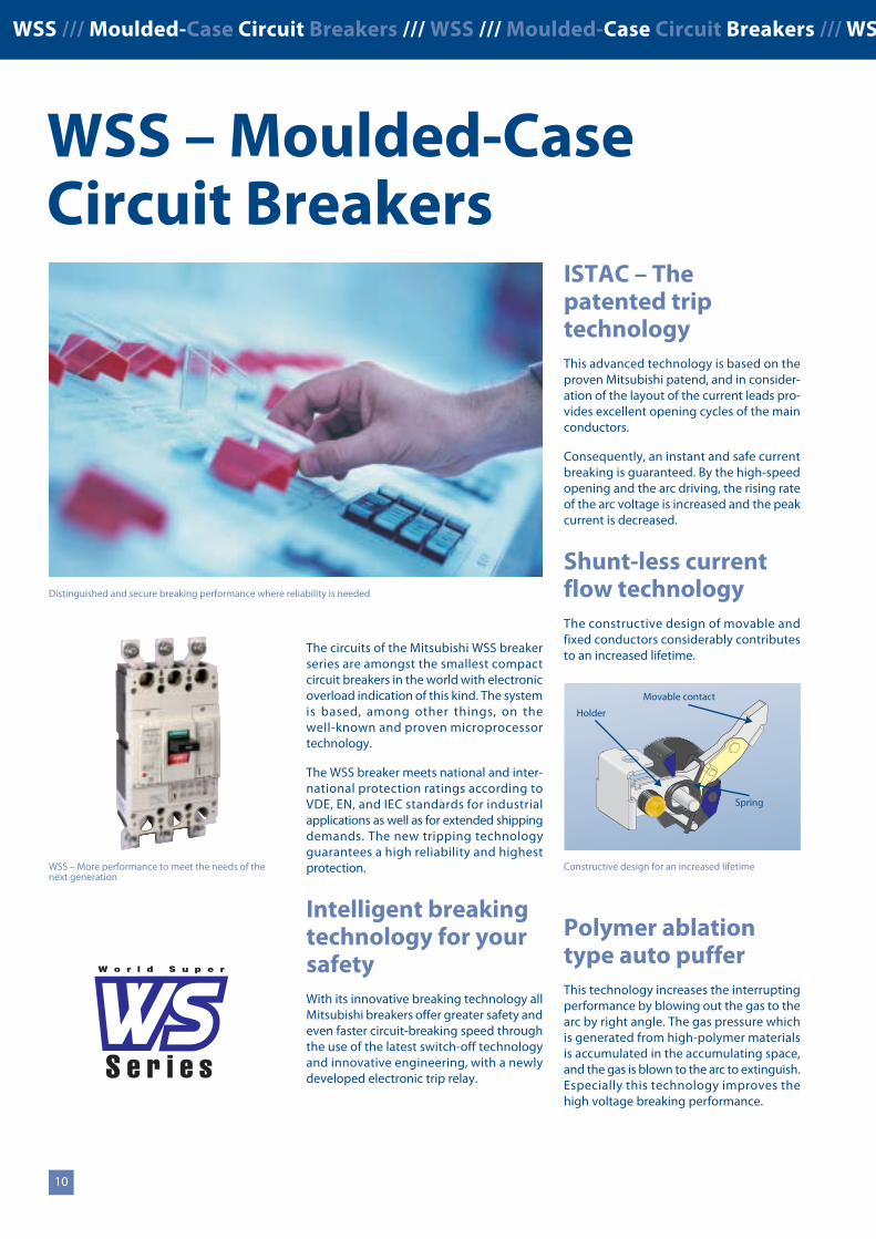
The circuits of the Mitsubishi WSS breakerseries are amongst the smallest compactcircuit breakers in the world with electronicoverload indication of this kind. The systemis based, among other things, on thewell-known and proven microprocessortechnology.
The WSS breaker meets national and inter-national protection ratings according toVDE, EN, and IEC standards for industrialapplications as well as for extended shippingdemands. The new tripping technologyguarantees a high reliability and highestprotection.
Intelligent breakingtechnology for yoursafetyWith its innovative breaking technology allMitsubishi breakers offer greater safety andeven faster circuit-breaking speed throughthe use of the latest switch-off technologyand innovative engineering, with a newlydeveloped electronic trip relay.
WSS – Moulded-CaseCircuit Breakers
ISTAC – Thepatented triptechnologyThis advanced technology is based on theproven Mitsubishi patend, and in consider-ation of the layout of the current leads pro-vides excellent opening cycles of the mainconductors.
Consequently, an instant and safe currentbreaking is guaranteed. By the high-speedopening and the arc driving, the rising rateof the arc voltage is increased and the peakcurrent is decreased.
Shunt-less currentflow technologyThe constructive design of movable andfixed conductors considerably contributesto an increased lifetime.
Polymer ablationtype auto pufferThis technology increases the interruptingperformance by blowing out the gas to thearc by right angle. The gas pressure whichis generated from high-polymer materialsis accumulated in the accumulating space,and the gas is blown to the arc to extinguish.Especially this technology improves thehigh voltage breaking performance.
Distinguished and secure breaking performance where reliability is needed
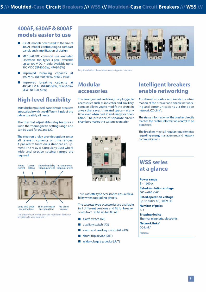
400AF, 630AF & 800AFmodels easier to use 630AF models downsized to the size of
400AF model, contributing to compactpanels and simplification of design.
MCCB-AC/DC common use (excludedElectronic trip type) 3-pole: availableup to 400 V DC, 4-pole: available up to500 V DC (NF400-SW, NF630-SW)
Improved breaking capacity at690 V AC (NF400-HEW, NF630-HEW)
Improved breaking capacity at400/415 V AC (NF400-SEW, NF630-SW/SEW, NF800-SEW)
High-level flexibilityMitsubishi moulded-case circuit breakersare available with two different kinds of triprelays to satisfy all needs.
The thermal adjustable relay features awide thermomagnetic setting range andcan be used for AC and DC.
The electronic relay provides options to setall relevant currents or time ranges.A pre-alarm function is standard equip-ment. The relay is particularly used wherewide and precise setting ranges arerequired.
ModularaccessoriesThe arrangement and design of pluggableaccessories such as indicator and auxiliarycontacts allows you to modify the circuit ina way that saves time and space – at anytime, even when built in and ready for oper-ation. The presence of separate circuitchambers makes the system even safer.
Thus cassette type accessories ensure flexi-bility when upgrading circuits.
The cassette type accessories are availablein 5 different versions and fit for breakerseries from 30 AF up to 800 AF:
alarm switch (AL)
auxiliary switch (AX)
alarm and auxiliary switch (AL+AX)
shunt trip device (SHT)
undervoltage trip device (UVT)
The electronic trip relay provives high-level flexibilityaccording to your demands
Ratedcurrent
Currentsetting
Short time-delaytripping current
Instantaneoustripping current
Long time-delayoperating time
Short time-delayoperating time
Pre-alarmcurrent
WSS seriesat a glance
Power range3 – 1600 A
Rated insulation voltage500 – 690 V AC
Rated operation voltageup to 690 V AC, 300 V DC
Number of poles3, 4
Tripping deviceThermal magnetic, electronic
Network links*CC-Link®
*optional
Easy installation of modular cassette type accessories.
WSS – More performance to meet the needs of thenext generation
Spring
Movable contact
Holder
Intelligent breakersenable networkingAdditional modules acquire status infor-mation of the breaker and enable network-ing and communications via the opennetwork CC-Link®.
The status information of the breaker directlyreaches the central information control to beprocessed.
The breakers meet all regular requirementsregarding energy management and networkcommunications.
Constructive design for an increased lifetime
11
WSS /// Moulded-Case Circuit Breakers /// WSS /// Moulded-Case Circuit Breakers /// WSS /// Moulded-Case Circuit Breakers /// WSS /// Moulded-Case Circuit Breakers /// WSS ///
10
The circuits of the Mitsubishi WSS breakerseries are amongst the smallest compactcircuit breakers in the world with electronicoverload indication of this kind. The systemis based, among other things, on thewell-known and proven microprocessortechnology.
The WSS breaker meets national and inter-national protection ratings according toVDE, EN, and IEC standards for industrialapplications as well as for extended shippingdemands. The new tripping technologyguarantees a high reliability and highestprotection.
Intelligent breakingtechnology for yoursafetyWith its innovative breaking technology allMitsubishi breakers offer greater safety andeven faster circuit-breaking speed throughthe use of the latest switch-off technologyand innovative engineering, with a newlydeveloped electronic trip relay.
WSS – Moulded-CaseCircuit Breakers
ISTAC – Thepatented triptechnologyThis advanced technology is based on theproven Mitsubishi patend, and in consider-ation of the layout of the current leads pro-vides excellent opening cycles of the mainconductors.
Consequently, an instant and safe currentbreaking is guaranteed. By the high-speedopening and the arc driving, the rising rateof the arc voltage is increased and the peakcurrent is decreased.
Shunt-less currentflow technologyThe constructive design of movable andfixed conductors considerably contributesto an increased lifetime.
Polymer ablationtype auto pufferThis technology increases the interruptingperformance by blowing out the gas to thearc by right angle. The gas pressure whichis generated from high-polymer materialsis accumulated in the accumulating space,and the gas is blown to the arc to extinguish.Especially this technology improves thehigh voltage breaking performance.
Distinguished and secure breaking performance where reliability is needed
400AF, 630AF & 800AFmodels easier to use 630AF models downsized to the size of
400AF model, contributing to compactpanels and simplification of design.
MCCB-AC/DC common use (excludedElectronic trip type) 3-pole: availableup to 400 V DC, 4-pole: available up to500 V DC (NF400-SW, NF630-SW)
Improved breaking capacity at690 V AC (NF400-HEW, NF630-HEW)
Improved breaking capacity at400/415 V AC (NF400-SEW, NF630-SW/SEW, NF800-SEW)
High-level flexibilityMitsubishi moulded-case circuit breakersare available with two different kinds of triprelays to satisfy all needs.
The thermal adjustable relay features awide thermomagnetic setting range andcan be used for AC and DC.
The electronic relay provides options to setall relevant currents or time ranges.A pre-alarm function is standard equip-ment. The relay is particularly used wherewide and precise setting ranges arerequired.
ModularaccessoriesThe arrangement and design of pluggableaccessories such as indicator and auxiliarycontacts allows you to modify the circuit ina way that saves time and space – at anytime, even when built in and ready for oper-ation. The presence of separate circuitchambers makes the system even safer.
Thus cassette type accessories ensure flexi-bility when upgrading circuits.
The cassette type accessories are availablein 5 different versions and fit for breakerseries from 30 AF up to 800 AF:
alarm switch (AL)
auxiliary switch (AX)
alarm and auxiliary switch (AL+AX)
shunt trip device (SHT)
undervoltage trip device (UVT)
The electronic trip relay provives high-level flexibilityaccording to your demands
Ratedcurrent
Currentsetting
Short time-delaytripping current
Instantaneoustripping current
Long time-delayoperating time
Short time-delayoperating time
Pre-alarmcurrent
WSS seriesat a glance
Power range3 – 1600 A
Rated insulation voltage500 – 690 V AC
Rated operation voltageup to 690 V AC, 300 V DC
Number of poles3, 4
Tripping deviceThermal magnetic, electronic
Network links*CC-Link®
*optional
Easy installation of modular cassette type accessories.
WSS – More performance to meet the needs of thenext generation
Spring
Movable contact
Holder
Intelligent breakersenable networkingAdditional modules acquire status infor-mation of the breaker and enable network-ing and communications via the opennetwork CC-Link®.
The status information of the breaker directlyreaches the central information control to beprocessed.
The breakers meet all regular requirementsregarding energy management and networkcommunications.
Constructive design for an increased lifetime
MS-N /// Magnetic Contactors /// MS-N /// Magnetic Contactors /// MS-N /// Magnetic Contactors /// MS-N /// Magnetic Contactors /// MS-N /// Magnetic Contactors /// MS-N ///
MS-N –Magnetic Contactors
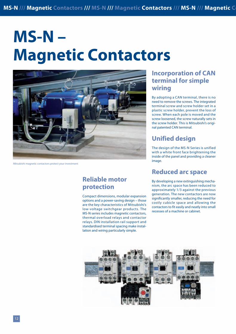
Reliable motorprotectionCompact dimensions, modular expansionoptions and a power-saving design – thoseare the key characteristics of Mitsubishi’slow-voltage switchgear products. TheMS-N series includes magnetic contactors,thermal overload relays and contactorrelays. DIN installation rail support andstandardised terminal spacing make instal-lation and wiring particularly simple.
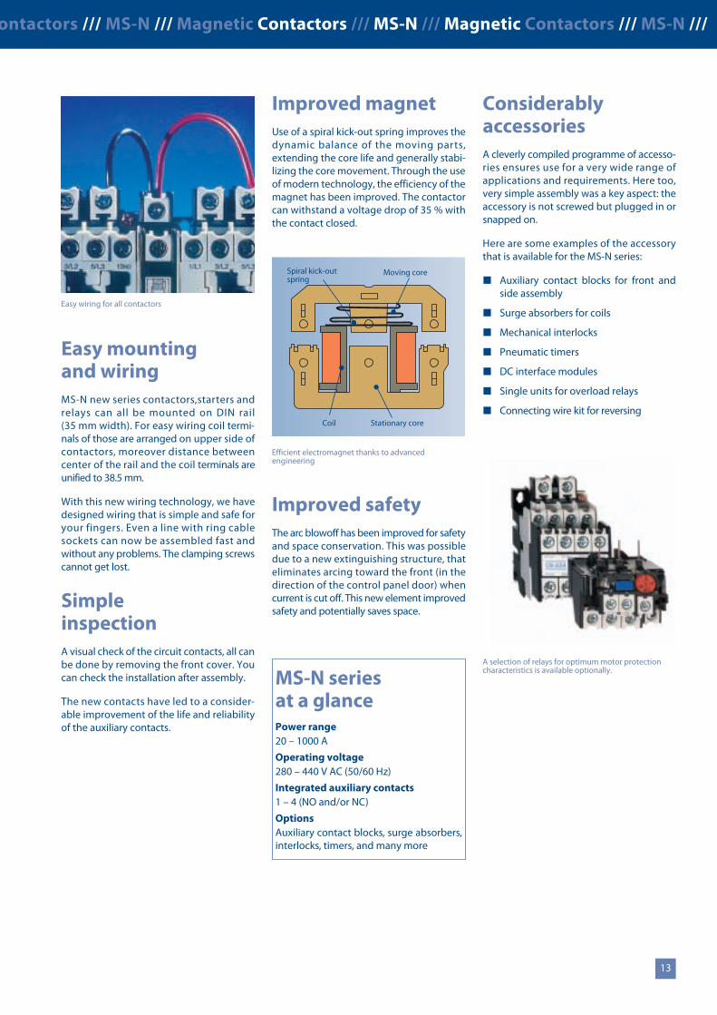
Easy mountingand wiringMS-N new series contactors,starters andrelays can all be mounted on DIN rail(35 mm width). For easy wiring coil termi-nals of those are arranged on upper side ofcontactors, moreover distance betweencenter of the rail and the coil terminals areunified to 38.5 mm.
With this new wiring technology, we havedesigned wiring that is simple and safe foryour fingers. Even a line with ring cablesockets can now be assembled fast andwithout any problems. The clamping screwscannot get lost.
SimpleinspectionA visual check of the circuit contacts, all canbe done by removing the front cover. Youcan check the installation after assembly.
The new contacts have led to a consider-able improvement of the life and reliabilityof the auxiliary contacts.
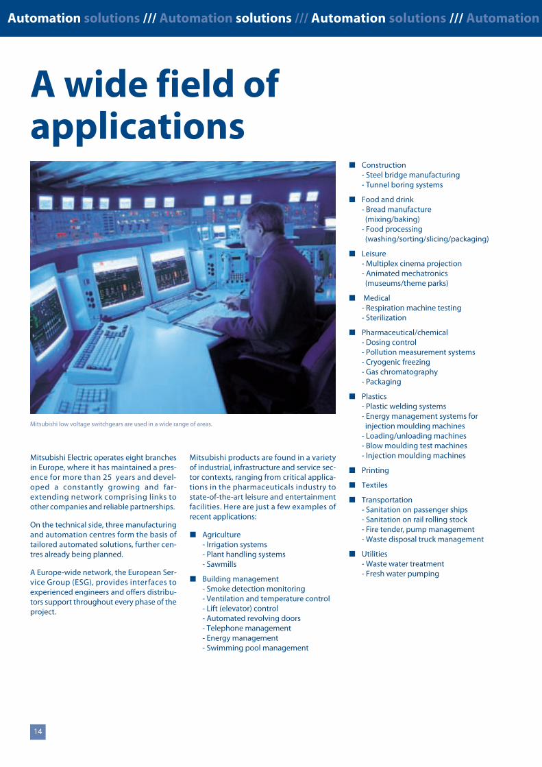
Improved magnetUse of a spiral kick-out spring improves thedynamic balance of the moving parts,extending the core life and generally stabi-lizing the core movement. Through the useof modern technology, the efficiency of themagnet has been improved. The contactorcan withstand a voltage drop of 35 % withthe contact closed.
Improved safetyThe arc blowoff has been improved for safetyand space conservation. This was possibledue to a new extinguishing structure, thateliminates arcing toward the front (in thedirection of the control panel door) whencurrent is cut off. This new element improvedsafety and potentially saves space.
12 13
MS-N seriesat a glancePower range20 – 1000 A
Operating voltage280 – 440 V AC (50/60 Hz)
Integrated auxiliary contacts1 – 4 (NO and/or NC)
OptionsAuxiliary contact blocks, surge absorbers,interlocks, timers, and many more
A selection of relays for optimum motor protectioncharacteristics is available optionally.
ConsiderablyaccessoriesA cleverly compiled programme of accesso-ries ensures use for a very wide range ofapplications and requirements. Here too,very simple assembly was a key aspect: theaccessory is not screwed but plugged in orsnapped on.
Here are some examples of the accessorythat is available for the MS-N series:
Auxiliary contact blocks for front andside assembly
Surge absorbers for coils
Mechanical interlocks
Pneumatic timers
DC interface modules
Single units for overload relays
Connecting wire kit for reversing
Incorporation of CANterminal for simplewiringBy adopting a CAN terminal, there is noneed to remove the screws. The integratedterminal screw and screw holder set in aplastic screw holder, prevent the loss ofscrew. When each pole is moved and thescrew loosened, the screw naturally sets inthe screw holder. This is Mitsubishi’s origi-nal patented CAN terminal.
Unified designThe design of the MS-N Series is unifiedwith a white front face brightening theinside of the panel and providing a cleanerimage.
Reduced arc spaceBy developing a new extinguishing mecha-nism, the arc space has been reduced toapproximately 1/3 against the previousgeneration. The new contactors are nowsignificantly smaller, reducing the need forcostly cubicle space and allowing thecontactors to fit easily and neatly into smallrecesses of a machine or cabinet.
Mitsubishi magnetic contactors protect your investment
Efficient electromagnet thanks to advancedengineering
Spiral kick-outspring
Coil
Moving core
Stationary core
Easy wiring for all contactors
MS-N /// Magnetic Contactors /// MS-N /// Magnetic Contactors /// MS-N /// Magnetic Contactors /// MS-N /// Magnetic Contactors /// MS-N /// Magnetic Contactors /// MS-N ///
MS-N –Magnetic Contactors
Reliable motorprotectionCompact dimensions, modular expansionoptions and a power-saving design – thoseare the key characteristics of Mitsubishi’slow-voltage switchgear products. TheMS-N series includes magnetic contactors,thermal overload relays and contactorrelays. DIN installation rail support andstandardised terminal spacing make instal-lation and wiring particularly simple.
Easy mountingand wiringMS-N new series contactors,starters andrelays can all be mounted on DIN rail(35 mm width). For easy wiring coil termi-nals of those are arranged on upper side ofcontactors, moreover distance betweencenter of the rail and the coil terminals areunified to 38.5 mm.
With this new wiring technology, we havedesigned wiring that is simple and safe foryour fingers. Even a line with ring cablesockets can now be assembled fast andwithout any problems. The clamping screwscannot get lost.
SimpleinspectionA visual check of the circuit contacts, all canbe done by removing the front cover. Youcan check the installation after assembly.
The new contacts have led to a consider-able improvement of the life and reliabilityof the auxiliary contacts.
Improved magnetUse of a spiral kick-out spring improves thedynamic balance of the moving parts,extending the core life and generally stabi-lizing the core movement. Through the useof modern technology, the efficiency of themagnet has been improved. The contactorcan withstand a voltage drop of 35 % withthe contact closed.
Improved safetyThe arc blowoff has been improved for safetyand space conservation. This was possibledue to a new extinguishing structure, thateliminates arcing toward the front (in thedirection of the control panel door) whencurrent is cut off. This new element improvedsafety and potentially saves space.
12 13
MS-N seriesat a glancePower range20 – 1000 A
Operating voltage280 – 440 V AC (50/60 Hz)
Integrated auxiliary contacts1 – 4 (NO and/or NC)
OptionsAuxiliary contact blocks, surge absorbers,interlocks, timers, and many more
A selection of relays for optimum motor protectioncharacteristics is available optionally.
ConsiderablyaccessoriesA cleverly compiled programme of accesso-ries ensures use for a very wide range ofapplications and requirements. Here too,very simple assembly was a key aspect: theaccessory is not screwed but plugged in orsnapped on.
Here are some examples of the accessorythat is available for the MS-N series:
Auxiliary contact blocks for front andside assembly
Surge absorbers for coils
Mechanical interlocks
Pneumatic timers
DC interface modules
Single units for overload relays
Connecting wire kit for reversing
Incorporation of CANterminal for simplewiringBy adopting a CAN terminal, there is noneed to remove the screws. The integratedterminal screw and screw holder set in aplastic screw holder, prevent the loss ofscrew. When each pole is moved and thescrew loosened, the screw naturally sets inthe screw holder. This is Mitsubishi’s origi-nal patented CAN terminal.
Unified designThe design of the MS-N Series is unifiedwith a white front face brightening theinside of the panel and providing a cleanerimage.
Reduced arc spaceBy developing a new extinguishing mecha-nism, the arc space has been reduced toapproximately 1/3 against the previousgeneration. The new contactors are nowsignificantly smaller, reducing the need forcostly cubicle space and allowing thecontactors to fit easily and neatly into smallrecesses of a machine or cabinet.
Mitsubishi magnetic contactors protect your investment
Efficient electromagnet thanks to advancedengineering
Spiral kick-outspring
Coil
Moving core
Stationary core
Easy wiring for all contactors
Automation solutions /// Automation solutions /// Automation solutions /// Automation solutions /// Automation solutions /// Automation solutions /// Automation solutions ///
Mitsubishi Electric operates eight branchesin Europe, where it has maintained a pres-ence for more than 25 years and devel-oped a constantly growing and far-extending network comprising links toother companies and reliable partnerships.
On the technical side, three manufacturingand automation centres form the basis oftailored automated solutions, further cen-tres already being planned.
A Europe-wide network, the European Ser-vice Group (ESG), provides interfaces toexperienced engineers and offers distribu-tors support throughout every phase of theproject.
A wide field ofapplications
Mitsubishi products are found in a varietyof industrial, infrastructure and service sec-tor contexts, ranging from critical applica-tions in the pharmaceuticals industry tostate-of-the-art leisure and entertainmentfacilities. Here are just a few examples ofrecent applications:
Agriculture- Irrigation systems- Plant handling systems- Sawmills
Building management- Smoke detection monitoring- Ventilation and temperature control- Lift (elevator) control- Automated revolving doors- Telephone management- Energy management- Swimming pool management
Mitsubishi low voltage switchgears are used in a wide range of areas.
14
Mitsubishi offer a wide range of automation equipment from PLCs and HMIs to CNC and EDM machines
A name to trustSince its beginnings in 1870, some45 companies use the Mitsubishi name,covering a spectrum of finance, commerceand industry.
The Mitsubishi brand name is recognizedaround the world as a symbol of premiumquality.
Mitsubishi Electric Corporation representsspace development, transportation, semicon-ductors, energy systems, communicationsand information processing, audio visualequipment, home electronics, building andenergy management and automation sys-tems, and has 237 factories and laboratoriesworldwide in over 121 countries.
Robots
Motion control and servos
Inverters
HMI and GOTs
Micro PLCs
EDM machines
CNCcontrollers
Laser machines
LV circuit protection
Modular PLCs
Construction- Steel bridge manufacturing- Tunnel boring systems
Food and drink- Bread manufacture
(mixing/baking)- Food processing
(washing/sorting/slicing/packaging)
Leisure- Multiplex cinema projection- Animated mechatronics
(museums/theme parks)
Medical- Respiration machine testing- Sterilization
Pharmaceutical/chemical- Dosing control- Pollution measurement systems- Cryogenic freezing- Gas chromatography- Packaging
Plastics- Plastic welding systems- Energy management systems for
injection moulding machines- Loading/unloading machines- Blow moulding test machines- Injection moulding machines
Printing
Textiles
Transportation- Sanitation on passenger ships- Sanitation on rail rolling stock- Fire tender, pump management- Waste disposal truck management
Utilities- Waste water treatment- Fresh water pumping
A world ofautomation solutions
This is why you can rely on a Mitsubishiautomation solution – because we know firsthand about the need for reliable, efficient,easy-to-use automation and control.
As one of the world’s leading companieswith a global turnover of 3.4 trillion Yen(approximately $30.8 billion), employingover 100 000 people, Mitsubishi Electrichas the resource and the commitment todeliver the ultimate in service and supportas well as the best products.
Technical Information Section
/// SUPER AE /// NF /// MS-N ///
1neue Seiten_GB.prnLVS-Family - Technical SectionFreitag, 30. Januar 2009 14:04:10
Farbprofil: DeaktiviertKomposit Standardbildschirm
2 MITSUBISHI ELECTRIC
More information?
This technical catalogue is designed to give an overview of the extensive range of Low-voltage Switchgears, Air-Circuit Breakers,Moulded-case Circuit Bbreakers, Magnetic Contactors, Thermal Overload Relays and Contactor Relays and its related accessories. If youcannot find the information you require in this catalogue, there are a number of ways you can get further details on configuration andtechnical issues, pricing and availability.
For technical issues visit the www.mitsubishi-automation.com website.
Our website provides a simple and fast way of accessing further technical data and up to the minute details on our products andservices. Manuals and catalogues are available in several different languages and can be downloaded for free.
For technical, configuration, pricing and availability issues contact our distributors and partners.
Mitsubishi partners and distributors are only too happy to help answer your technical questions or help with configuration building.For a list of Mitsubishi partners please see the back of this catalogue or alternatively take a look at the “contact us” section of ourwebsite.
About this technical catalogue
This catalogue is a guide to the range of products available. For detailed configuration rules, system building, installation and configura-tion the associated product manuals must be read. You must satisfy yourself that any system you design with the products in this cata-logue is fit for purpose, meets your requires and conforms to the product configuration rules as defined in the product manuals.
Specifications are subject to change without notice. All trademarks acknowledged.
© Mitsubishi Electric Europe B.V., Factory Automation - European Business Group
2neue Seiten_GB.prnLVS-Family - Technical SectionFreitag, 30. Januar 2009 14:04:14
Farbprofil: DeaktiviertKomposit Standardbildschirm
3MITSUBISHI ELECTRIC
CONTENTS ///
1
2
3
4
5
6
7
8
9
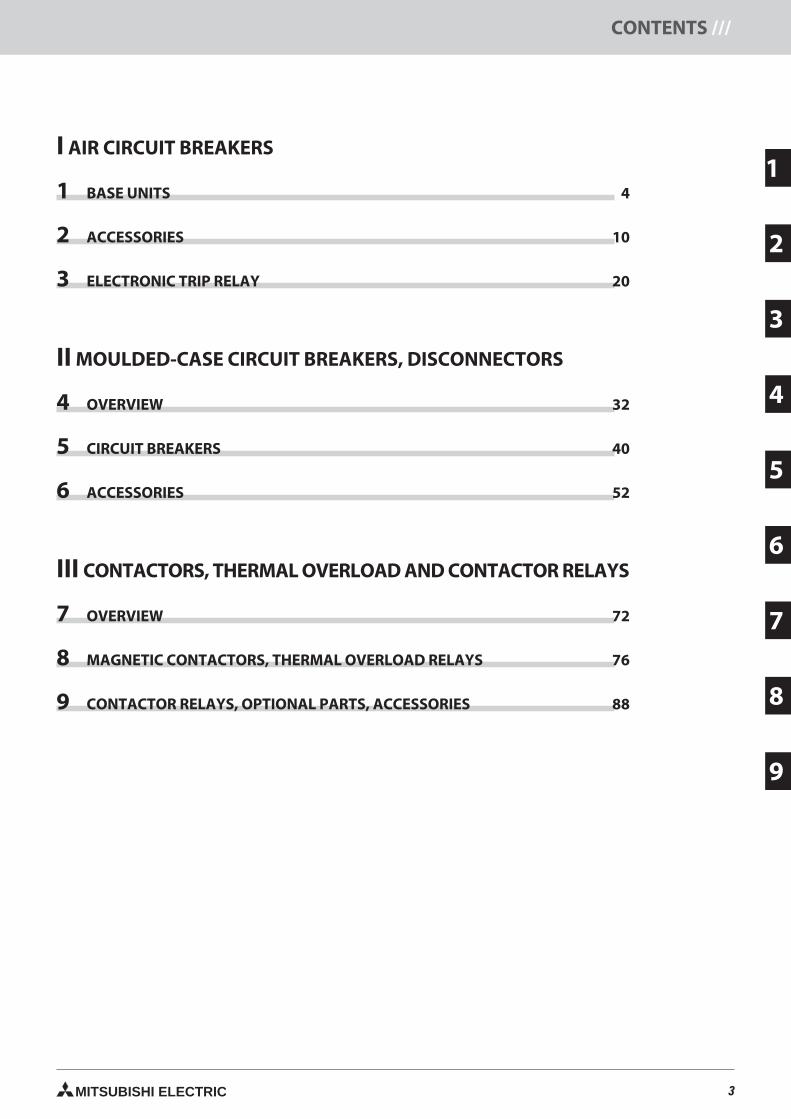
I AIR CIRCUIT BREAKERS
1 BASE UNITS 4
2 ACCESSORIES 10
3 ELECTRONIC TRIP RELAY 20
II MOULDED-CASE CIRCUIT BREAKERS, DISCONNECTORS
4 OVERVIEW 32
5 CIRCUIT BREAKERS 40
6 ACCESSORIES 52
III CONTACTORS, THERMAL OVERLOAD AND CONTACTOR RELAYS
7 OVERVIEW 72
8 MAGNETIC CONTACTORS, THERMAL OVERLOAD RELAYS 76
9 CONTACTOR RELAYS, OPTIONAL PARTS, ACCESSORIES 88
4 MITSUBISHI ELECTRIC
1
SAE
–B
ASI
CC
OM
PO
NEN
TS/// SAE BASE UNITS
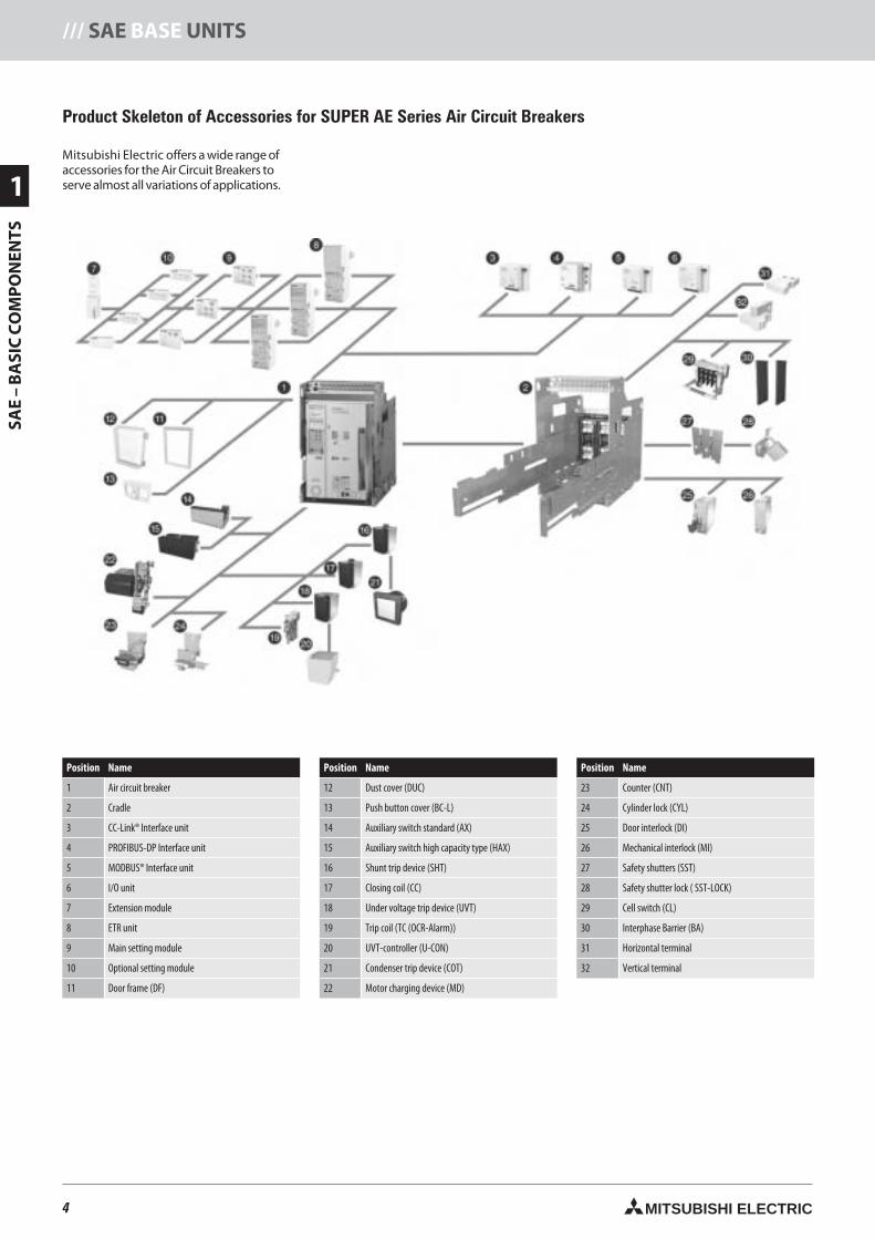
Product Skeleton of Accessories for SUPER AE Series Air Circuit Breakers
Mitsubishi Electric offers a wide range ofaccessories for the Air Circuit Breakers toserve almost all variations of applications.
Position Name
1 Air circuit breaker
2 Cradle
3 CC-Link® Interface unit
4 PROFIBUS-DP Interface unit
5 MODBUS® Interface unit
6 I/O unit
7 Extension module
8 ETR unit
9 Main setting module
10 Optional setting module
11 Door frame (DF)
Position Name
12 Dust cover (DUC)
13 Push button cover (BC-L)
14 Auxiliary switch standard (AX)
15 Auxiliary switch high capacity type (HAX)
16 Shunt trip device (SHT)
17 Closing coil (CC)
18 Under voltage trip device (UVT)
19 Trip coil (TC (OCR-Alarm))
20 UVT-controller (U-CON)
21 Condenser trip device (COT)
22 Motor charging device (MD)
Position Name
23 Counter (CNT)
24 Cylinder lock (CYL)
25 Door interlock (DI)
26 Mechanical interlock (MI)
27 Safety shutters (SST)
28 Safety shutter lock ( SST-LOCK)
29 Cell switch (CL)
30 Interphase Barrier (BA)
31 Horizontal terminal
32 Vertical terminal
4neue Seiten_GB.prnLVS-Family - Technical SectionFreitag, 30. Januar 2009 14:04:25
Farbprofil: DeaktiviertKomposit Standardbildschirm
5MITSUBISHI ELECTRIC
1
SAE
–B
ASI
CC
OM
PO
NEN
TS
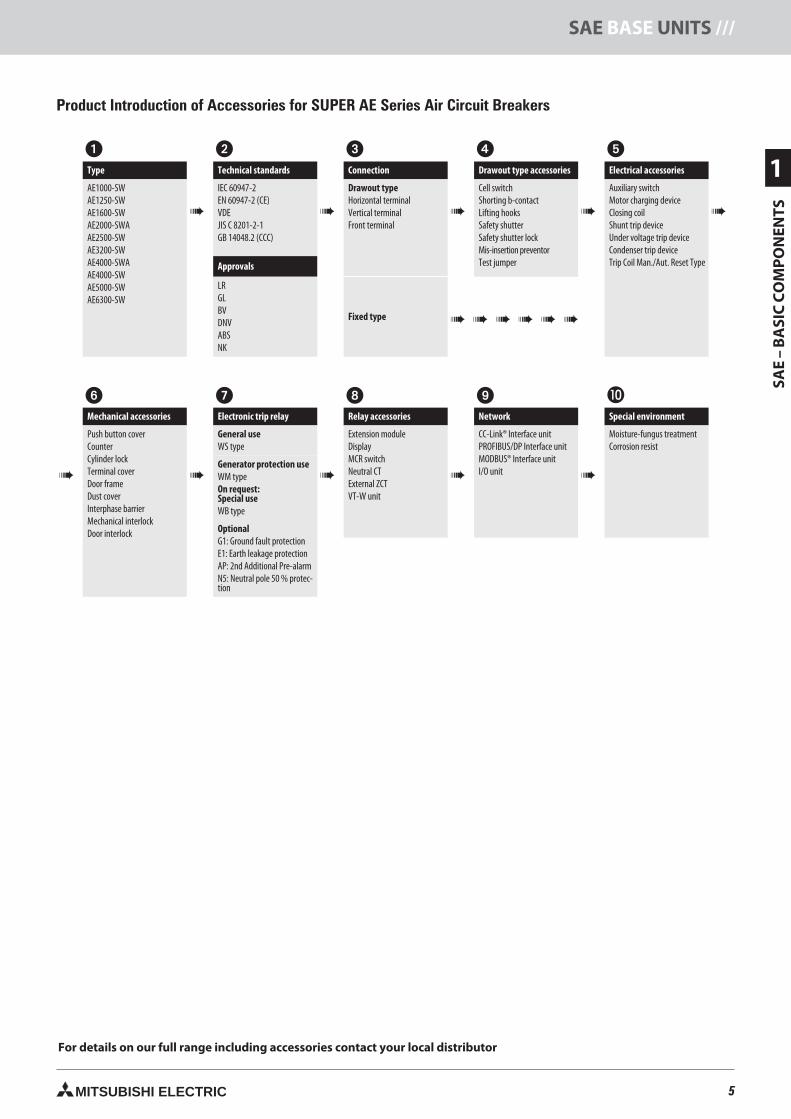
SAE BASE UNITS ///
Type
Technical standards
Connection
Drawout type accessories
Electrical accessories
AE1000-SWAE1250-SWAE1600-SWAE2000-SWAAE2500-SWAE3200-SWAE4000-SWAAE4000-SWAE5000-SWAE6300-SW
IEC 60947-2EN 60947-2 (CE)VDEJIS C 8201-2-1GB 14048.2 (CCC)
Drawout typeHorizontal terminalVertical terminalFront terminal
Cell switchShorting b-contactLifting hooksSafety shutterSafety shutter lockMis-insertion preventorTest jumper
Auxiliary switchMotor charging deviceClosing coilShunt trip deviceUnder voltage trip deviceCondenser trip deviceTrip Coil Man./Aut. Reset TypeApprovals
LRGLBVDNVABSNK
Fixed type
Mechanical accessories
Electronic trip relay
Relay accessories
Network
Special environment
Push button coverCounterCylinder lockTerminal coverDoor frameDust coverInterphase barrierMechanical interlockDoor interlock
General useWS type
Extension moduleDisplayMCR switchNeutral CTExternal ZCTVT-W unit
CC-Link® Interface unitPROFIBUS/DP Interface unitMODBUS® Interface unitI/O unit
Moisture-fungus treatmentCorrosion resist
Generator protection useWM typeOn request:Special useWB type
OptionalG1: Ground fault protectionE1: Earth leakage protectionAP: 2nd Additional Pre-alarmN5: Neutral pole 50 % protec-tion
Product Introduction of Accessories for SUPER AE Series Air Circuit Breakers
For details on our full range including accessories contact your local distributor
5neue Seiten_GB.prnLVS-Family - Technical SectionFreitag, 30. Januar 2009 14:04:29
Farbprofil: DeaktiviertKomposit Standardbildschirm
6 MITSUBISHI ELECTRIC
1
SAE
–B
ASI
CC
OM
PO
NEN
TS/// SAE BASE UNITS
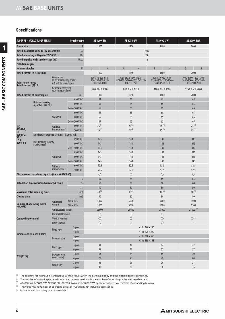
Specifications
SUPER AE – WORLD SUPER SERIES Breaker type AE 1000- SW AE 1250- SW AE 1600 -SW AE 2000- SWA
Frame size A 1000 1250 1600 2000
Rated insulation voltage (AC V) 50/60 Hz Ui 1000
Rated operating voltage (AC V) 50/60 Hz Ue 690
Rated impulse withstand voltage (kV) Uimp 12
Pollution degree 3
Number of poles P 3 4 3 4 3 4 3 4
Rated current in (CT rating) 1000 1250 1600 2000
Adjustment rangeRated current (A) Ir
General use(current rating adjustable0.5 to 1.0 x In 0.05 step)
500-550-600-650-700-750-800-850-
900-950-1000
625-687.5-750-812.5-875-937.5-1000-1062.5-1125-
1187.5-1250
800-880-960-1040-1120-1200-1280-1360-
1440-1520-1600
1000-1100-1200-1300-1400-1500-1600-1700-
1800-1900-2000
Generator protection(current rating fixed) 400 ≤ Ir ≤ 1000 800 ≤ Ir ≤ 1250 1000 ≤ Ir ≤ 1600 1250 ≤ Ir ≤ 2000
Rated current of neutral pole (A) 1000 1250 1600 2000
IEC60947-2,EN60947-2,VDE,JIS C8201-2-1
Ultimate breakingcapacity ICu (kA rms)
690 V AC 65 65 65 65
600 V AC 65 65 65 65
240 – 500 V AC 65 65 65 65
With MCR
690 V AC 65 65 65 65
600 V AC 65 65 65 65
240 – 500 V AC 65 65 65 65
Withoutinstantaneous
690 V AC 25 25 25 25
500 V AC 25 25 25 25
Rated service breaking capacity ICs (kA rms) % lcu
Rated making capacityICM (kA, peak)
690 V AC 143 143 143 143
600 V AC 143 143 143 143
240 – 500 V AC 143 143 143 143
With MCR
690 V AC 143 143 143 143
600 V AC 143 143 143 143
240 – 500 V AC 143 143 143 143
Withoutinstantaneous
690 V AC 52.5 52.5 52.5 52.5
500 V AC 52.5 52.5 52.5 52.5
Disconnector: switching capacity (6 x Ir at 690V AC)
Rated short time withstand current (kA rms) ICW
1s 65 65 65 65
2s 60 60 60 60
3s 50 50 50 50
Maximum total breaking time (ms) 40 40 40 40
Closing time (ms) 80 80 80 80
Number of operating cycles
(ON/OFF)
With ratedcurrent
500 V AC In 5000 5000 5000 1500
690 V AC In 5000 5000 5000 1500
Without rated current 25000 25000 25000 25000
Connecting terminal
Horizontal terminal —
Vertical terminal
Front terminal —
Dimensions (H x W x D mm)
Fixed type3-pole 410 x 340 x 290
4-pole 410 x 425 x 290
Drawout type3-pole 430 x 300 x 368
4-pole 430 x 385 x 368
Weight (kg)
Fixed type3-pole 41 41 42 47
4-pole 51 51 52 57
Drawout type(with cradle)
3-pole 64 64 65 70
4-pole 78 78 79 84
Cradle only3-pole 26 26 26 31
4-pole 30 30 30 35
The columns for "without instantaneous" are the values when the bare main body and the external relay is combined. The number of operating cycles without rated current also include the number of operating cycles with rated current. AE4000-SW, AE5000-SW, AE6300-SW, AE2000-SWA and AE4000-SWA apply for only vertical terminal of connecting terminal. This value means number of operating cycles of ACB's body not including accessories. Products with low rating types is available.
6neue Seiten_GB.prnLVS-Family - Technical SectionFreitag, 30. Januar 2009 14:04:36
Farbprofil: DeaktiviertKomposit Standardbildschirm
7MITSUBISHI ELECTRIC
1
SAE
–B
ASI
CC
OM
PO
NEN
TS
SAE BASE UNITS ///
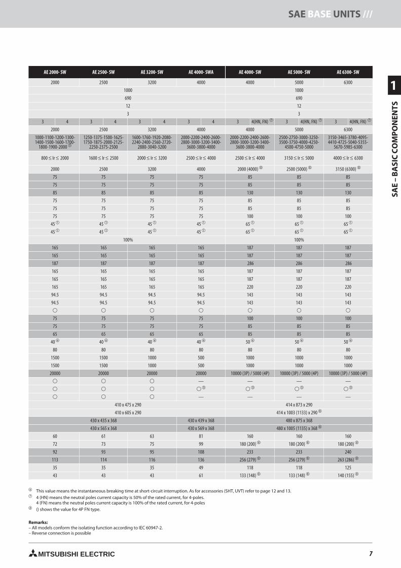
AE 2000- SW AE 2500- SW AE 3200- SW AE 4000- SWA AE 4000- SW AE 5000- SW AE 6300- SW
2000 2500 3200 4000 4000 5000 6300
1000 1000
690 690
12 12
3 3
3 4 3 4 3 4 3 4 3 4(HN, FN) 3 4(HN, FN) 3 4(HN, FN)
2000 2500 3200 4000 4000 5000 6300
1000-1100-1200-1300-1400-1500-1600-1700-
1800-1900-2000
1250-1375-1500-1625-1750-1875-2000-2125-
2250-2375-2500
1600-1760-1920-2080-2240-2400-2560-2720-
2880-3040-3200
2000-2200-2400-2600-2800-3000-3200-3400-
3600-3800-4000
2000-2200-2400-2600-2800-3000-3200-3400-
3600-3800-4000
2500-2750-3000-3250-3500-3750-4000-4250-
4500-4750-5000
3150-3465-3780-4095-4410-4725-5040-5355-
5670-5985-6300
800 ≤ Ir ≤ 2000 1600 ≤ Ir ≤ 2500 2000 ≤ Ir ≤ 3200 2500 ≤ Ir ≤ 4000 2500 ≤ Ir ≤ 4000 3150 ≤ Ir ≤ 5000 4000 ≤ Ir ≤ 6300
2000 2500 3200 4000 2000 (4000) 2500 (5000) 3150 (6300)
75 75 75 75 85 85 85
75 75 75 75 85 85 85
85 85 85 85 130 130 130
75 75 75 75 85 85 85
75 75 75 75 85 85 85
75 75 75 75 100 100 100
45 45 45 45 65 65 65
45 45 45 45 65 65 65
100% 100%
165 165 165 165 187 187 187
165 165 165 165 187 187 187
187 187 187 187 286 286 286
165 165 165 165 187 187 187
165 165 165 165 187 187 187
165 165 165 165 220 220 220
94.5 94.5 94.5 94.5 143 143 143
94.5 94.5 94.5 94.5 143 143 143
75 75 75 75 100 100 100
75 75 75 75 85 85 85
65 65 65 65 85 85 85
40 40 40 40 50 50 50
80 80 80 80 80 80 80
1500 1500 1000 500 1000 1000 1000
1500 1500 1000 500 1000 1000 1000
20000 20000 20000 20000 10000 (3P) / 5000 (4P) 10000 (3P) / 5000 (4P) 10000 (3P) / 5000 (4P)
— — — —
— — — —
410 x 475 x 290 414 x 873 x 290
410 x 605 x 290 414 x 1003 (1133) x 290
430 x 435 x 368 430 x 439 x 368 480 x 875 x 368
430 x 565 x 368 430 x 569 x 368 480 x 1005 (1135) x 368
60 61 63 81 160 160 160
72 73 75 99 180 (200) 180 (200) 180 (200)
92 93 95 108 233 233 240
113 114 116 136 256 (279) 256 (279) 263 (286)
35 35 35 49 118 118 125
43 43 43 61 133 (148) 133 (148) 140 (155)
This value means the instantaneous breaking time at short-circuit interruption. As for accessories (SHT, UVT) refer to page 12 and 13. 4 (HN) means the neutral poles current capacity is 50% of the rated current, for 4-poles.
4 (FN) means the neutral poles current capacity is 100% of the rated current, for 4-poles () shows the value for 4P FN type.
Remarks:– All models conform the isolating function according to IEC 60947-2.– Reverse connection is possible
7neue Seiten_GB.prnLVS-Family - Technical SectionFreitag, 30. Januar 2009 14:04:41
Farbprofil: DeaktiviertKomposit Standardbildschirm
8 MITSUBISHI ELECTRIC
1
SAE
–B
ASI
CC
OM
PO
NEN
TS/// SAE BASE UNITS
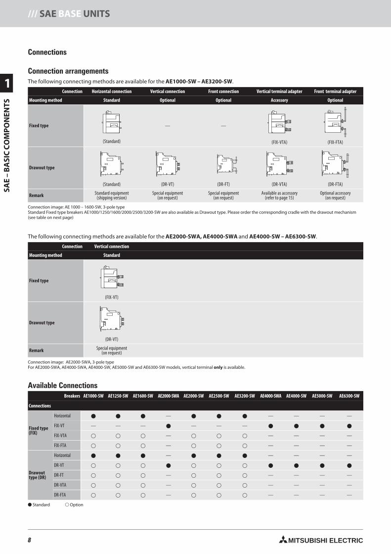
Connections
Connection arrangementsThe following connecting methods are available for the AE1000-SW – AE3200-SW.
Connection Horizontal connection Vertical connection Front connection Vertical terminal adapter Front terminal adapter
Mounting method Standard Optional Optional Accessory Optional
Fixed type
(Standard)
— —
(FIX-VTA) (FIX-FTA)
Drawout type
(Standard) (DR-VT) (DR-FT) (DR-VTA) (DR-FTA)
Remark Standard equipment(shipping version)
Special equipment(on request)
Special equipment(on request)
Available as accessory(refer to page 15)
Optional accessory(on request)
Connection image: AE 1000 – 1600-SW, 3-pole typeStandard Fixed type breakers AE1000/1250/1600/2000/2500/3200-SW are also available as Drawout type. Please order the corresponding cradle with the drawout mechanism(see table on next page)
The following connecting methods are available for the AE2000-SWA, AE4000-SWA and AE4000-SW – AE6300-SW.
Connection Vertical connection
Mounting method Standard
Fixed type
(FIX-VT)
Drawout type
(DR-VT)
Remark Special equipment(on request)
Connection image: AE2000-SWA, 3-pole typeFor AE2000-SWA, AE4000-SWA, AE4000-SW, AE5000-SW and AE6300-SW models, vertical terminal only is available.
Available ConnectionsBreakers AE1000-SW AE1250-SW AE1600-SW AE2000-SWA AE2000-SW AE2500-SW AE3200-SW AE4000-SWA AE4000-SW AE5000-SW AE6300-SW
Connections
Fixed type(FIX)
Horizontal — — — — —
FIX-VT — — — — — —
FIX-VTA — — — — —
FIX-FTA — — — — —
Drawouttype (DR)
Horizontal — — — — —
DR-VT
DR-FT — — — — —
DR-VTA — — — — —
DR-FTA — — — — —
Standard Option
8neue Seiten_GB.prnLVS-Family - Technical SectionFreitag, 30. Januar 2009 14:05:12
Farbprofil: DeaktiviertKomposit Standardbildschirm
9MITSUBISHI ELECTRIC
1
SAE
–B
ASI
CC
OM
PO
NEN
TS
SAE BASE UNITS ///
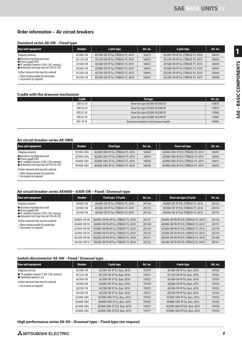
Order information – Air circuit breakers
Standard series AE-SW – Fixed type
Base unit equipment Breaker 3-pole type Art. no. 4-pole type Art. no.
Shipping contents: Electronic trip Relay base unit Power supply PW310 auxiliary contacts (5 NO, 5 NC contacts) Automatic reset type trip coil (TCA-AL-W)
Further elements that must be ordered: Main setting module for protection Accessories as required
AE1000-SW AE1000-SW 3P Fix, ETRBASE-P3, AX10 168373 AE1000-SW 4P Fix, ETRBASE-P3, AX10 168434AE1250-SW AE1250-SW 3P Fix, ETRBASE-P3, AX10 168435 AE1250-SW 4P Fix, ETRBASE-P3, AX10 168436AE1600-SW AE1600-SW 3P Fix, ETRBASE-P3, AX10 168437 AE1600-SW 4P Fix, ETRBASE-P3, AX10 168438AE2000-SW AE2000-SW 3P Fix, ETRBASE-P3, AX10 168443 AE2000-SW 4P Fix, ETRBASE-P3, AX10 168444AE2500-SW AE2500-SW 3P Fix, ETRBASE-P3, AX10 168445 AE2500-SW 4P Fix, ETRBASE-P3, AX10 168446AE3200-SW AE3200-SW 3P Fix, ETRBASE-P3, AX10 168447 AE3200-SW 4P Fix, ETRBASE-P3, AX10 168448
Air circuit breaker series AE4000 – 6300-SW – Fixed / Drawout type
Base unit equipment Breaker Fixed type 3/4-pole Art. no. Draw-out type 3/4-pole Art. no.
Shipping contents: Electronic trip Relay base unit Power supply PW310 auxiliary contacts (5 NO, 5 NC contacts) Automatic reset type trip coil (TCA-AL-W)
Further elements that must be ordered: Main setting module for protection Accessories as required
AE4000-SW AE4000-SW 3P Fix, ETRBASE-P3, AX10 205144 AE4000-SW 3P D/O, ETRBASE-P3, AX10 205153AE5000-SW AE5000-SW 3P Fix, ETRBASE-P3, AX10 205145 AE5000-SW 3P D/O, ETRBASE-P3, AX10 205154AE6300-SW AE6300-SW 3P Fix, ETRBASE-P3, AX10 205146 AE6300-SW 3P D/O, ETRBASE-P3, AX10 205155
AE4000-SW HN AE4000-SW HN 4P Fix, ETRBASE-P3, AX10 205147 AE4000-SW HN 4P D/O, ETRBASE-P3, AX10 205156AE4000-SW FN AE4000-SW FN 4P Fix, ETRBASE-P3, AX10 205148 AE4000-SW FN 4P D/O, ETRBASE-P3, AX10 205157AE5000-SW HN AE5000-SW HN 4P Fix, ETRBASE-P3, AX10 205149 AE5000-SW HN 4P D/O, ETRBASE-P3, AX10 205158AE5000-SW FN AE5000-SW FN 4P Fix, ETRBASE-P3, AX10 205150 AE5000-SW FN 4P D/O, ETRBASE-P3, AX10 205159AE6300-SW HN AE6300-SW HN 4P Fix, ETRBASE-P3, AX10 205151 AE6300-SW HN 4P D/O, ETRBASE-P3, AX10 205160AE6300-SW FN AE6300-SW FN 4P Fix, ETRBASE-P3, AX10 205152 AE6300-SW FN 4P D/O, ETRBASE-P3, AX10 205161
Air circuit breaker series AE-SWA
Base unit equipment Breaker Fixed type Art. no. Draw-out type Art. no.
Shipping contents: Electronic trip Relay base unit Power supply PW310 auxiliary contacts (5 NO, 5 NC contacts) Automatic reset type trip coil (TCA-AL-W)
Further elements that must be ordered: Main setting module for protection Accessories as required
AE2000-SWA AE2000-SWA 4P Fix, ETRBASE-P3, AX10 168440 AE2000-SWA 3P D/O, ETRBASE-P3, AX10 168441AE2000-SWA AE2000-SWA 3P Fix, ETRBASE-P3, AX10 168439 AE2000-SWA 4P D/O, ETRBASE-P3, AX10 168442AE4000-SWA AE4000-SWA 3P Fix, ETRBASE-P3, AX10 168449 AE4000-SWA 3P D/O, ETRBASE-P3, AX10 168451AE4000-SWA AE4000-SWA 4P Fix, ETRBASE-P3, AX10 168450 AE4000-SWA 4P D/O, ETRBASE-P3, AX10 168452
Switch-disconnector AE-SW – Fixed / Drawout type
Base unit equipment Breaker 3-pole type Art. no. 4-pole type Art. no.
Shipping contents: 10 auxiliary contacts (5 NO, 5 NC contacts) Switching capacity IR x 6
Further elements that must be ordered: Accessories as required
AE1000-SW AE1000-SW 3P Fix, Bare, AX10 193919 AE1000-SW 4P Fix, Bare, AX10 193920AE1250-SW AE1250-SW 3P Fix, Bare, AX10 193921 AE1250-SW 4P Fix, Bare, AX10 193922AE1600-SW AE1600-SW 3P Fix, Bare, AX10 193923 AE1600-SW 4P Fix, Bare, AX10 193924AE2000-SW AE2000-SW 3P Fix, Bare, AX10 193929 AE2000-SW 4P Fix, Bare, AX10 193930AE2500-SW AE2500-SW 3P Fix, Bare, AX10 193931 AE2500-SW 4P Fix, Bare, AX10 193932AE3200-SW AE3200-SW 3P Fix, Bare, AX10 193933 AE3200-SW 4P Fix, Bare, AX10 193934
AE2000-SWA AE2000-SWA 3P Fix, Bare, AX10 193925 AE2000-SWA 4P Fix, Bare, AX10 193926AE4000-SWA AE4000-SWA 3P Fix, Bare, AX10 193935 AE4000-SWA 4P Fix, Bare, AX10 193936AE2000-SWA AE2000-SWA 3P D/O, Bare, AX10 193927 AE2000-SWA 4P D/O, Bare, AX10 193928AE4000-SWA AE4000-SWA 3P D/O, Bare, AX10 193937 AE4000-SWA 4P D/O, Bare, AX10 193938
High performance series AE-SH – Drawout type – Fixed type (on request)
Cradle with the drawout mechanismCradle For type Art. no.
CRD163-W Draw Out type AE1000-AE1600 3P 170078CRD164-W Draw Out type AE1000-AE1600 4P 170079CRD323-W Draw Out type AE2000-AE3200 3P 170080CRD324-W Draw Out type AE2000-AE3200 4P 170081REC-FD-W Drawout mechanism with drawout handle 169004
9neue Seiten_GB.prnLVS-Family - Technical SectionFreitag, 30. Januar 2009 14:05:17
Farbprofil: DeaktiviertKomposit Standardbildschirm
10 MITSUBISHI ELECTRIC
2
SAE
–A
CC
ESSO
RIE
S/// SAE ACCESSORIES
MITSUBISHI
DP1
TEST.68
.76
.84 .92
OVER1.0
Ip
RESET
TEST
L/SLOCK
()
TYPEG1
0.1
0.3
0.5 0.7
1.00.9
Ig(xIn)
TRIP
3.0
3.01.5
1.50.8
0.80.5
0.50.3
0.3.15
.15.10 .10
ALARM
Tg(s)
RUN
Ig
Tg
GRF
TYPE WM1
15
20
TL(s)(s)
ILx1.22530
40 60
.06.06
IL(x(xIr)
1.51.0
51.1
1.15
1.2
Isd(xIr)1.5
22.5
33.5 4 4.5
5
Ii(xIr)
INST
10
10
12
12
16
16
8
86
6442 2MRC
ON
OFF
I2t
I2t
0.5
0.50.3
0.30.10.1
Tsd(s)
Ir(A)=
RUN
100
80
60
40
%ILERR
.
PAL
S
Isd
Tsd
IpI2t
I
Ii(xIL)
ILTL
TAL
L
MITSUBISHI
Time delay
0.5s or more
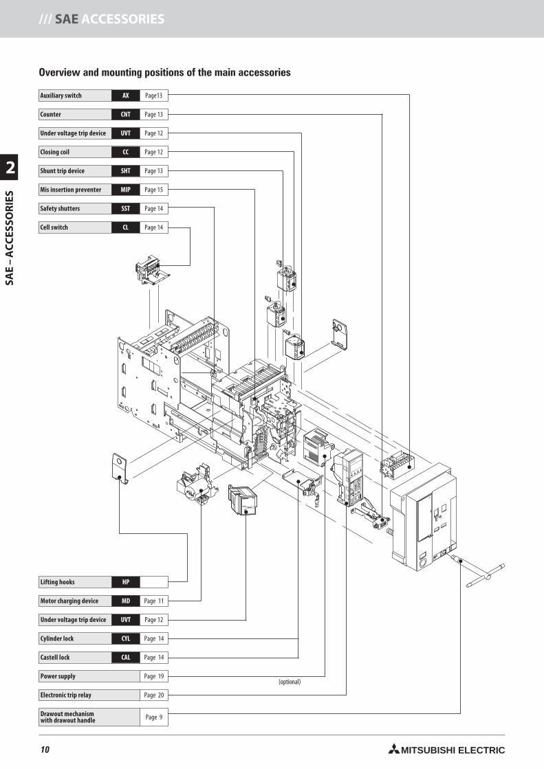
Overview and mounting positions of the main accessories
Auxiliary switch AX Page13
Counter CNT Page 13
Under voltage trip device UVT Page 12
Closing coil CC Page 12
Shunt trip device SHT Page 13
Mis insertion preventer MIP Page 15
Safety shutters SST Page 14
Cell switch CL Page 14
(optional)
Lifting hooks HP
Motor charging device MD Page 11
Under voltage trip device UVT Page 12
Cylinder lock CYL Page 14
Castell lock CAL Page 14
Power supply Page 19
Electronic trip relay Page 20
Drawout mechanismwith drawout handle Page 9
10neue Seiten_GB.prnLVS-Family - Technical SectionFreitag, 30. Januar 2009 14:05:30
Farbprofil: DeaktiviertKomposit Standardbildschirm
11MITSUBISHI ELECTRIC
2
SAE
–A
CC
ESSO
RIE
S
SAE ACCESSORIES ///
Overview and description on the optional accessories
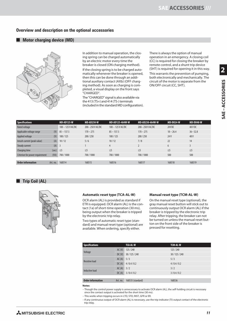
Motor charging device (MD)
In addition to manual operation, the clos-ing spring can be charged automaticallyby an electric motor every time thebreaker is closed (ON charging method).
If the closing spring is to be charged auto-matically whenever the breaker is opened,then this can be done through an addi-tional auxiliary contact (AXb) (OFF charg-ing method). As soon as charging is com-pleted, a visual display on the front says"CHARGED".The "CHARGED" signal is also available viathe 413 (TS+) and 414 (TS-) terminals(included in the standard MD configuration).
There is always the option of manualoperation in an emergency. A closing coil(CC) is required for closing the breaker byremote control, and a shunt trip device(SHT) is required for opening it in this way.
This warrants the prevention of pumping,both electronically and mechanically. Thecircuit of the motor is separate from theON/OFF circuit (CC, SHT).
Specifications MD-AD125-W MD-AD250-W MD-AD125-4A4W-W MD-AD250-4A4W-W MD-DO24-W MD-DO48-W
Rated voltage 100 – 125 V AC/DC 200– 250 V AC/DC 100 – 125 V AC/DC 200– 250 V AC/DC 24 V DC 48 V DC
Applicable voltage range (V) 85 – 137.5 170 – 275 85 – 137.5 170 – 275 18 – 26.4 36– 52.8
Applied voltage (V) 100 / 125 200 / 250 100 / 125 200 / 250 24 V 48 V
Inrush current (peak value) (A) 10 / 12 5 / 6 10 / 12 7 / 8 22 14
Steady current (A) 3 1 4 2 6 3
Charging time (sec) ≤5 ≤5 ≤5 ≤5 ≤5 ≤5
Criterion for power requirement (VA) 700 / 1000 700 / 1000 700 / 1000 700 / 1000 500 500
Order information Art. no. 168514 168515 168516 168517 168518 168519
Trip Coil (AL)
Automatic reset type (TCA-AL-W)
OCR alarm (AL) is provided as standard ifETR is equipped. OCR alarm (AL) is the con-tact (1a) of short-time operation (30 ms),being output when the breaker is trippedby the electronic trip relay.
Two types of automatic reset type (stan-dard) and manual reset type (optional) areavailable. When ordering, specify either.
Manual reset type (TCM-AL-W)
On the manual reset type (optional), thegray manual reset button will stick out tocontinuously output OCR alarm (AL) if thebreaker is tripped by the electronic triprelay. After tripping, the breaker can notbe turned on unless the manual reset but-ton on the front side of the breaker ispressed for resetting.
Specifications TCA-AL-W TCM-AL-W
VoltageAC (V) 125 / 240 125 / 240
DC (V) 30 / 125 / 240 30 / 125 / 240
Resistive loadAC (A) 5 / 3 5 / 3
DC (A) 4 / 0.4 / 0.2 4 / 0.4 / 0.2
Inductive loadAC (A) 3 / 2 3 / 2
DC (A) 3 / 0.4 / 0.2 3 / 0.4 / 0.2
Order information Art. no. 168535 (standard) 168536
Notes:– Though the control power supply is unnecessary to activate OCR alarm (AL), the self-holding circuit is necessary– since the contact output is activated for the short time (30 ms).– This works when tripping occurs in LTD, STD, INST, GFR or ER.– If any continuous output of OCR alarm (AL) is necessary, use the trip indicator (TI) output contact of the electronic
trip relay.
11neue Seiten_GB.prnLVS-Family - Technical SectionFreitag, 30. Januar 2009 14:06:01
Farbprofil: DeaktiviertKomposit Standardbildschirm
12 MITSUBISHI ELECTRIC
2
SAE
–A
CC
ESSO
RIE
S/// SAE ACCESSORIES
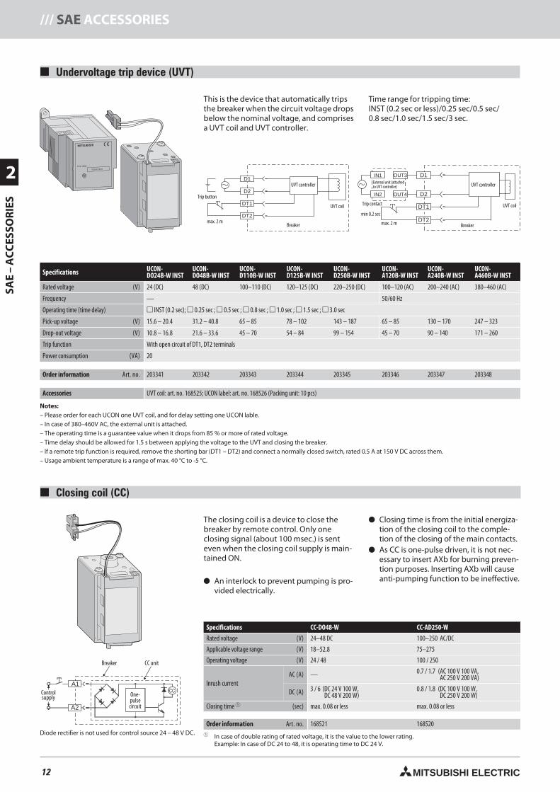
Undervoltage trip device (UVT)
This is the device that automatically tripsthe breaker when the circuit voltage dropsbelow the nominal voltage, and comprisesa UVT coil and UVT controller.
Time range for tripping time:INST (0.2 sec or less)/0.25 sec/0.5 sec/0.8 sec/1.0 sec/1.5 sec/3 sec.
Specifications UCON-DO24B-W INST
UCON-DO48B-W INST
UCON-D110B-W INST
UCON-D125B-W INST
UCON-D250B-W INST
UCON-A120B-W INST
UCON-A240B-W INST
UCON-A460B-W INST
Rated voltage (V) 24 (DC) 48 (DC) 100–110 (DC) 120–125 (DC) 220–250 (DC) 100–120 (AC) 200–240 (AC) 380–460 (AC)
Frequency — 50/60 Hz
Operating time (time delay) INST (0.2 sec); 0.25 sec ; 0.5 sec ; 0.8 sec ; 1.0 sec ; 1.5 sec ; 3.0 sec
Pick-up voltage (V) 15.6 – 20.4 31.2 – 40.8 65 – 85 78 – 102 143 – 187 65 – 85 130 – 170 247 – 323
Drop-out voltage (V) 10.8 – 16.8 21.6 – 33.6 45 – 70 54 – 84 99 – 154 45 – 70 90 – 140 171 – 260
Trip function With open circuit of DT1, DT2 terminals
Power consumption (VA) 20
Order information Art. no. 203341 203342 203343 203344 203345 203346 203347 203348
Accessories UVT coil: art. no. 168525; UCON label: art. no. 168526 (Packing unit: 10 pcs)
Notes:– Please order for each UCON one UVT coil, and for delay setting one UCON lable.– In case of 380–460V AC, the external unit is attached.– The operating time is a guarantee value when it drops from 85 % or more of rated voltage.– Time delay should be allowed for 1.5 s between applying the voltage to the UVT and closing the breaker.– If a remote trip function is required, remove the shorting bar (DT1 – DT2) and connect a normally closed switch, rated 0.5 A at 150 V DC across them.– Usage ambient temperature is a range of max. 40 °C to -5 °C.
D1
D2
DT1
DT2
D1
D2
DT1
DT2
OUT3
OUT4
IN1
IN2
Closing coil (CC)
The closing coil is a device to close thebreaker by remote control. Only oneclosing signal (about 100 msec.) is senteven when the closing coil supply is main-tained ON.
An interlock to prevent pumping is pro-vided electrically.
Closing time is from the initial energiza-tion of the closing coil to the comple-tion of the closing of the main contacts.
As CC is one-pulse driven, it is not nec-essary to insert AXb for burning preven-tion purposes. Inserting AXb will causeanti-pumping function to be ineffective.
Specifications CC-DO48-W CC-AD250-W
Rated voltage (V) 24–48 DC 100–250 AC/DC
Applicable voltage range (V) 18–52.8 75–275
Operating voltage (V) 24 / 48 100 / 250
Inrush currentAC (A) — 0.7 / 1.7 (AC 100 V 100 VA,
AC 250 V 200 VA)
DC (A) 3 / 6 (DC 24 V 100 W,(DC 48 V 200 W)
0.8 / 1.8 (DC 100 V 100 W,DC 250 V 200 W)
Closing time (sec) max. 0.08 or less max. 0.08 or less
Order information Art. no. 168521 168520 In case of double rating of rated voltage, it is the value to the lower rating.
Example: In case of DC 24 to 48, it is operating time to DC 24 V.
MITSUBISHI
Time delay
0.5s or more
A1
A2
Breaker
Controlsupply One-
pulsecircuit
CC unit
Diode rectifier is not used for control source 24 – 48 V DC.
Trip button
UVT controller
max. 2 mBreaker
UVT coil
UVT controller
max. 2 m
min 0.2 sec
Breaker
UVT coilTrip contact
External unit (attachedto UVT controller)
12neue Seiten_GB.prnLVS-Family - Technical SectionFreitag, 30. Januar 2009 14:06:16
Farbprofil: DeaktiviertKomposit Standardbildschirm
13MITSUBISHI ELECTRIC
2
SAE
–A
CC
ESSO
RIE
S
SAE ACCESSORIES ///
00000258
C1
C2 SHT
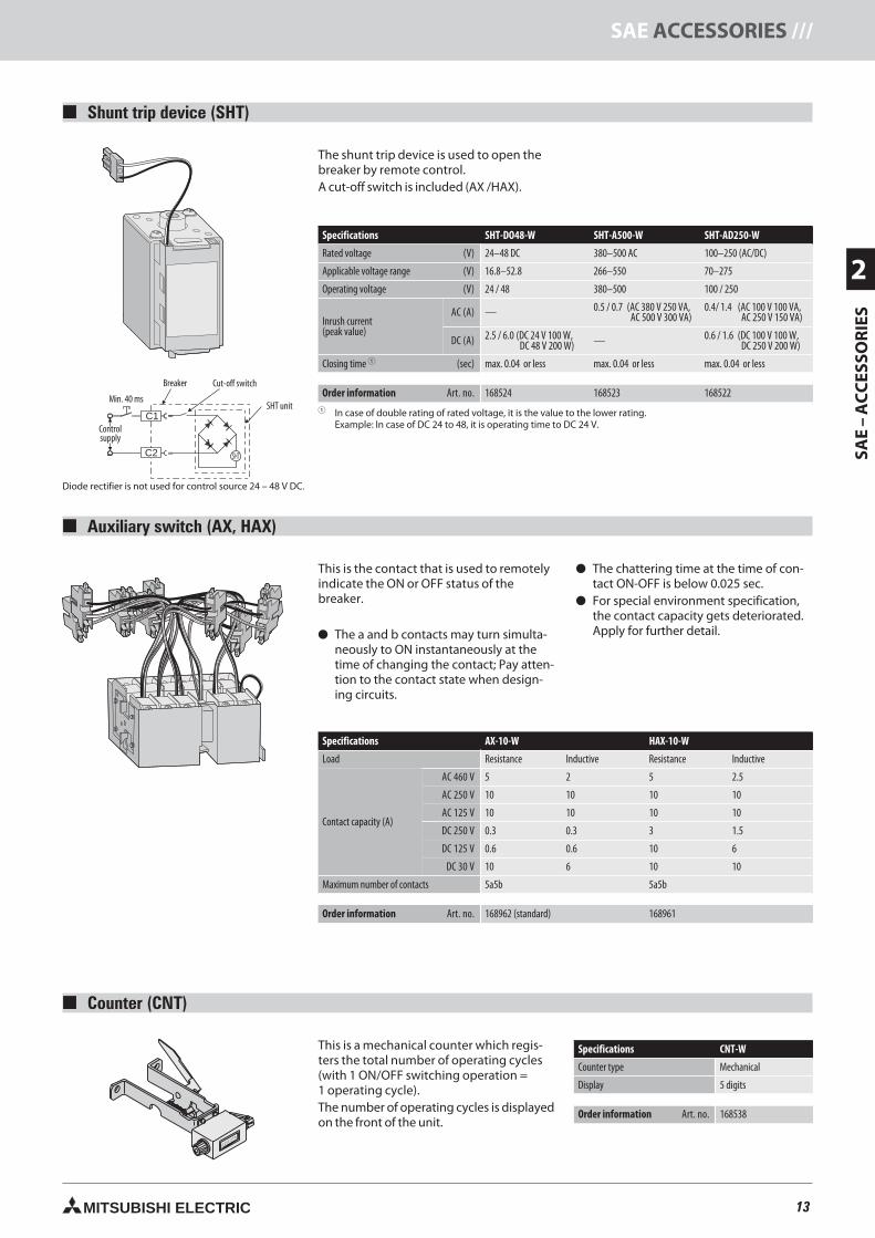
Shunt trip device (SHT)
The shunt trip device is used to open thebreaker by remote control.A cut-off switch is included (AX /HAX).
SHT-DO48-W SHT-A500-W SHT-AD250-W
Rated voltage (V) 24–48 DC 380–500 AC 100–250 (AC/DC)
Applicable voltage range (V) 16.8–52.8 266–550 70–275
Operating voltage (V) 24 / 48 380–500 100 / 250
Inrush current(peak value)
AC (A) — 0.5 / 0.7 (AC 380 V 250 VA,( AC 500 V 300 VA)
0.4/ 1.4 (AC 100 V 100 VA,( AC 250 V 150 VA)
DC (A) 2.5 / 6.0 (DC 24 V 100 W,DC 48 V 200 W) — 0.6 / 1.6 (DC 100 V 100 W,
( DC 250 V 200 W)
Closing time (sec) max. 0.04 or less max. 0.04 or less max. 0.04 or less
Order information Art. no. 168524 168523 168522 In case of double rating of rated voltage, it is the value to the lower rating.
Example: In case of DC 24 to 48, it is operating time to DC 24 V.
Auxiliary switch (AX, HAX)
Specifications AX-10-W HAX-10-W
Load Resistance Inductive Resistance Inductive
Contact capacity (A)
AC 460 V 5 2 5 2.5
AC 250 V 10 10 10 10
AC 125 V 10 10 10 10
DC 250 V 0.3 0.3 3 1.5
DC 125 V 0.6 0.6 10 6
DC 30 V 10 6 10 10
Maximum number of contacts 5a5b 5a5b
Order information Art. no. 168962 (standard) 168961
This is the contact that is used to remotelyindicate the ON or OFF status of thebreaker.
The a and b contacts may turn simulta-neously to ON instantaneously at thetime of changing the contact; Pay atten-tion to the contact state when design-ing circuits.
The chattering time at the time of con-tact ON-OFF is below 0.025 sec.
For special environment specification,the contact capacity gets deteriorated.Apply for further detail.
Counter (CNT)
This is a mechanical counter which regis-ters the total number of operating cycles(with 1 ON/OFF switching operation =1 operating cycle).The number of operating cycles is displayedon the front of the unit.
Specifications CNT-W
Counter type Mechanical
Display 5 digits
Order information Art. no. 168538
Diode rectifier is not used for control source 24 – 48 V DC.
Breaker
Controlsupply
SHT unitMin. 40 ms
Cut-off switch
13neue Seiten_GB.prnLVS-Family - Technical SectionFreitag, 30. Januar 2009 14:06:32
Farbprofil: DeaktiviertKomposit Standardbildschirm
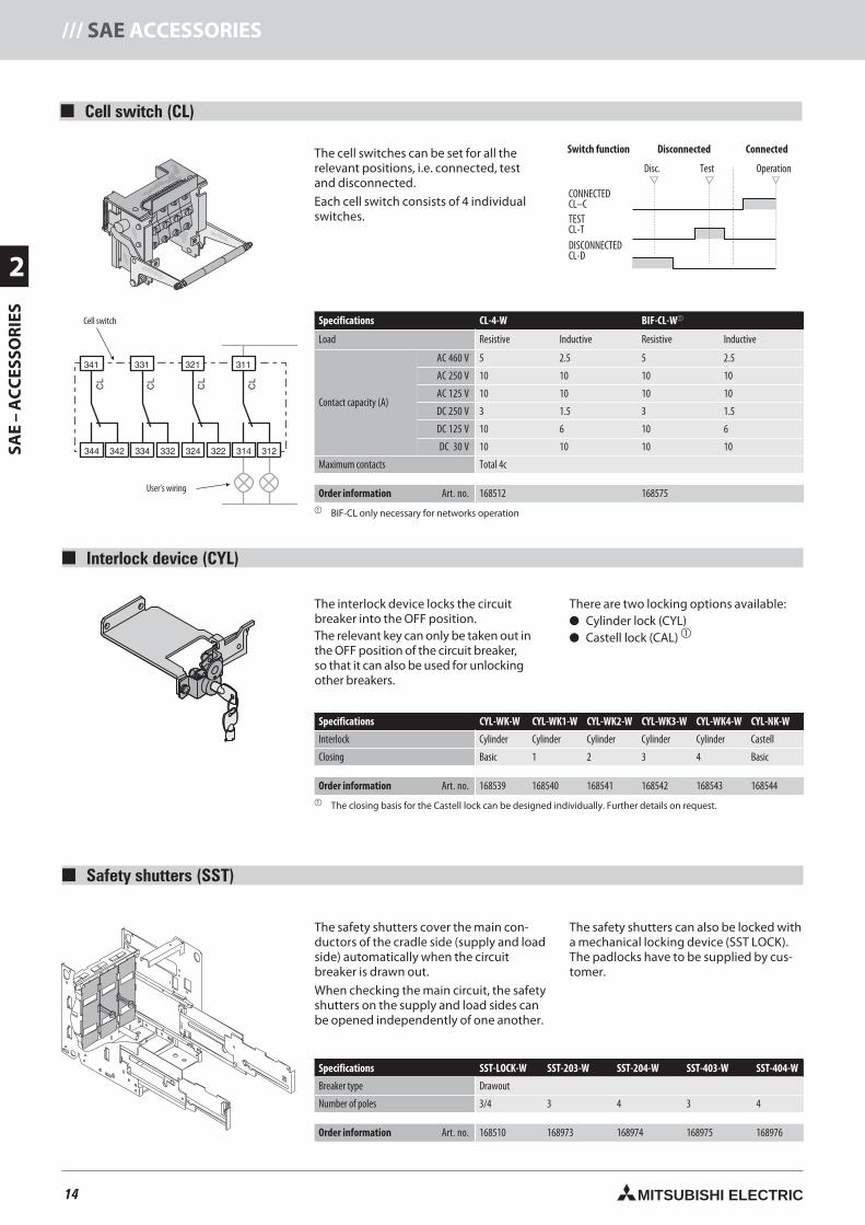
14 MITSUBISHI ELECTRIC
2
SAE
–A
CC
ESSO
RIE
S/// SAE ACCESSORIES
discon.
Disconnected Connected
test operation
Cell switch (CL)
The cell switches can be set for all therelevant positions, i.e. connected, testand disconnected.
Each cell switch consists of 4 individualswitches.
Specifications CL-4-W BIF-CL-W
Load Resistive Inductive Resistive Inductive
Contact capacity (A)
AC 460 V 5 2.5 5 2.5
AC 250 V 10 10 10 10
AC 125 V 10 10 10 10
DC 250 V 3 1.5 3 1.5
DC 125 V 10 6 10 6
DC 30 V 10 10 10 10
Maximum contacts Total 4c
Order information Art. no. 168512 168575 BIF-CL only necessary for networks operation
Switch function
CONNECTEDCL–CTESTCL-TDISCONNECTEDCL-D
Disconnected Connected
Disc. Test Operation
The interlock device locks the circuitbreaker into the OFF position.The relevant key can only be taken out inthe OFF position of the circuit breaker,so that it can also be used for unlockingother breakers.
There are two locking options available: Cylinder lock (CYL) Castell lock (CAL)
Specifications CYL-WK-W CYL-WK1-W CYL-WK2-W CYL-WK3-W CYL-WK4-W CYL-NK-W
Interlock Cylinder Cylinder Cylinder Cylinder Cylinder Castell
Closing Basic 1 2 3 4 Basic
Order information Art. no. 168539 168540 168541 168542 168543 168544 The closing basis for the Castell lock can be designed individually. Further details on request.
The safety shutters cover the main con-ductors of the cradle side (supply and loadside) automatically when the circuitbreaker is drawn out.
When checking the main circuit, the safetyshutters on the supply and load sides canbe opened independently of one another.
The safety shutters can also be locked witha mechanical locking device (SST LOCK).The padlocks have to be supplied by cus-tomer.
Specifications SST-LOCK-W SST-203-W SST-204-W SST-403-W SST-404-W
Breaker type Drawout
Number of poles 3/4 3 4 3 4
Order information Art. no. 168510 168973 168974 168975 168976
User's wiring
Cell switch
Interlock device (CYL)
Safety shutters (SST)
14neue Seiten_GB.prnLVS-Family - Technical SectionFreitag, 30. Januar 2009 14:06:52
Farbprofil: DeaktiviertKomposit Standardbildschirm
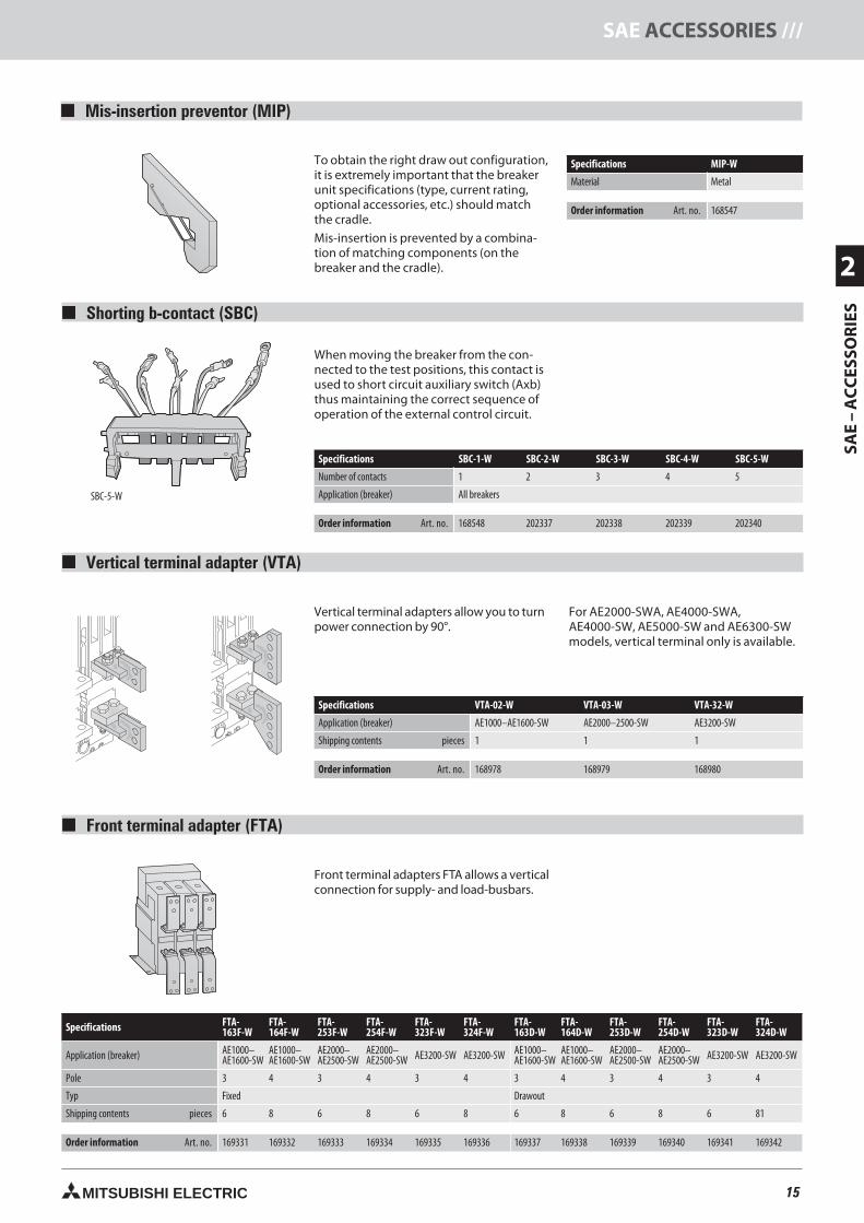
15MITSUBISHI ELECTRIC
2
SAE
–A
CC
ESSO
RIE
S
SAE ACCESSORIES ///
Mis-insertion preventor (MIP)
To obtain the right draw out configuration,it is extremely important that the breakerunit specifications (type, current rating,optional accessories, etc.) should matchthe cradle.
Mis-insertion is prevented by a combina-tion of matching components (on thebreaker and the cradle).
Specifications MIP-W
Material Metal
Order information Art. no. 168547
Shorting b-contact (SBC)
When moving the breaker from the con-nected to the test positions, this contact isused to short circuit auxiliary switch (Axb)thus maintaining the correct sequence ofoperation of the external control circuit.
Specifications SBC-1-W SBC-2-W SBC-3-W SBC-4-W SBC-5-W
Number of contacts 1 2 3 4 5
Application (breaker) All breakers
Order information Art. no. 168548 202337 202338 202339 202340
Vertical terminal adapter (VTA)
Vertical terminal adapters allow you to turnpower connection by 90°.
For AE2000-SWA, AE4000-SWA,AE4000-SW, AE5000-SW and AE6300-SWmodels, vertical terminal only is available.
Specifications VTA-02-W VTA-03-W VTA-32-W
Application (breaker) AE1000–AE1600-SW AE2000–2500-SW AE3200-SW
Shipping contents pieces 1 1 1
Order information Art. no. 168978 168979 168980
Front terminal adapter (FTA)
Front terminal adapters FTA allows a verticalconnection for supply- and load-busbars.
Specifications FTA-163F-W
FTA-164F-W
FTA-253F-W
FTA-254F-W
FTA-323F-W
FTA-324F-W
FTA-163D-W
FTA-164D-W
FTA-253D-W
FTA-254D-W
FTA-323D-W
FTA-324D-W
Application (breaker) AE1000–AE1600-SW
AE1000–AE1600-SW
AE2000–AE2500-SW
AE2000–AE2500-SW AE3200-SW AE3200-SW AE1000–
AE1600-SWAE1000–AE1600-SW
AE2000–AE2500-SW
AE2000–AE2500-SW AE3200-SW AE3200-SW
Pole 3 4 3 4 3 4 3 4 3 4 3 4
Typ Fixed Drawout
Shipping contents pieces 6 8 6 8 6 8 6 8 6 8 6 81
Order information Art. no. 169331 169332 169333 169334 169335 169336 169337 169338 169339 169340 169341 169342
SBC-5-W
15neue Seiten_GB.prnLVS-Family - Technical SectionFreitag, 30. Januar 2009 14:07:07
Farbprofil: DeaktiviertKomposit Standardbildschirm
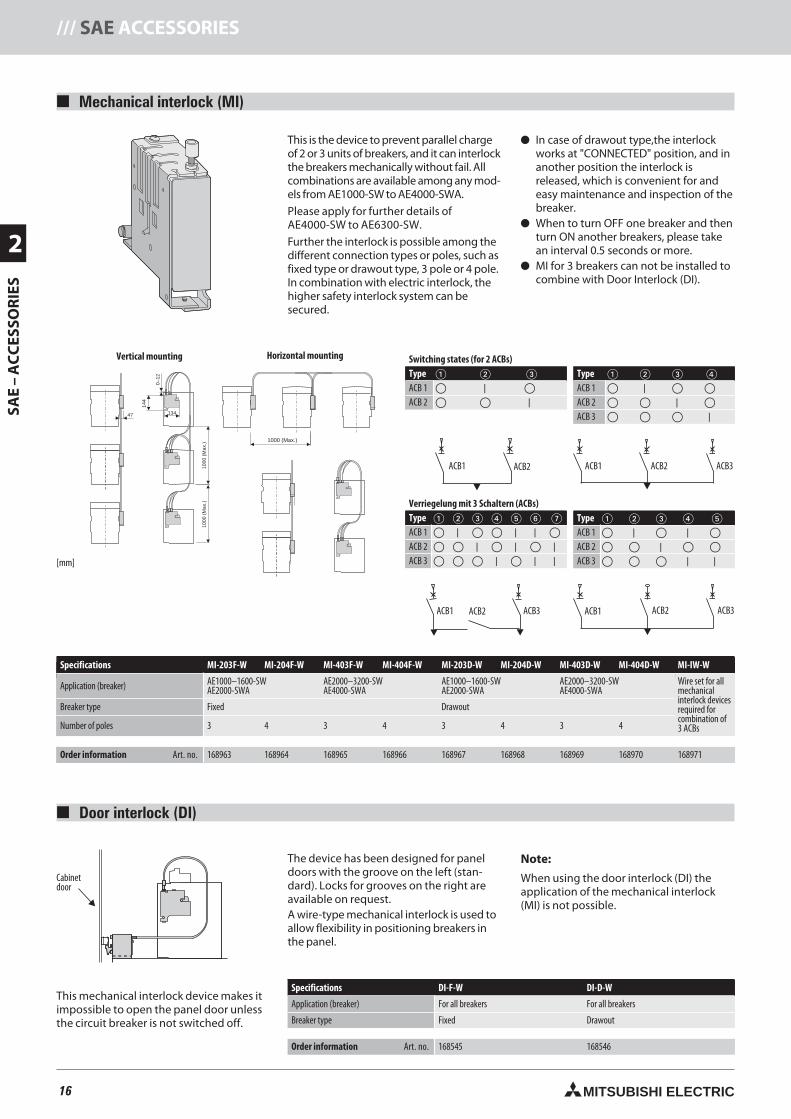
16 MITSUBISHI ELECTRIC
2
SAE
–A
CC
ESSO
RIE
S/// SAE ACCESSORIES
Mechanical interlock (MI)
1000 (Max.)
134
144
0–12
1000
(Max
.)
47
1000
(Max
.)
This is the device to prevent parallel chargeof 2 or 3 units of breakers, and it can interlockthe breakers mechanically without fail. Allcombinations are available among any mod-els from AE1000-SW to AE4000-SWA.
Please apply for further details ofAE4000-SW to AE6300-SW.
Further the interlock is possible among thedifferent connection types or poles, such asfixed type or drawout type, 3 pole or 4 pole.In combination with electric interlock, thehigher safety interlock system can besecured.
In case of drawout type,the interlockworks at "CONNECTED" position, and inanother position the interlock isreleased, which is convenient for andeasy maintenance and inspection of thebreaker.
When to turn OFF one breaker and thenturn ON another breakers, please takean interval 0.5 seconds or more.
MI for 3 breakers can not be installed tocombine with Door Interlock (DI).
Technische Daten MI-203F-W MI-204F-W MI-403F-W MI-404F-W MI-203D-W MI-204D-W MI-403D-W MI-404D-W MI-IW-W
Anwendungsbereich (Schalter) AE1000–1600-SWAE2000-SWA
AE2000–3200-SWAE4000-SWA
AE1000–1600-SWAE2000-SWA
AE2000–3200-SWAE4000-SWA
Bowdenzug-Satz, wird für dieVerriegelung vondrei Schalternbenötigt
Einbauart Festeinbau Einschubtechnik
Anzahl der Pole 3 4 3 4 3 4 3 4
Bestellangaben Art.-Nr. 168963 168964 168965 168966 168967 168968 168969 168970 168971
Horizontal mountingVertical mounting
[mm]
Switching states (for 2 ACBs)Type ACB 1 |
ACB 2 |
Verriegelung mit 3 Schaltern (ACBs)Type ACB 1 | | |
ACB 2 | | |ACB 3 | | |
Type ACB 1 |
ACB 2 |
ACB 3 |
Type ACB 1 | |
ACB 2 |
ACB 3 | |
ACB1 ACB2 ACB3ACB1 ACB2
ACB3ACB1 ACB2 ACB3ACB1 ACB2
Door interlock (DI)
Specifications MI-203F-W MI-204F-W MI-403F-W MI-404F-W MI-203D-W MI-204D-W MI-403D-W MI-404D-W MI-IW-W
Application (breaker) AE1000–1600-SWAE2000-SWA
AE2000–3200-SWAE4000-SWA
AE1000–1600-SWAE2000-SWA
AE2000–3200-SWAE4000-SWA
Wire set for allmechanicalinterlock devicesrequired forcombination of3 ACBs
Breaker type Fixed Drawout
Number of poles 3 4 3 4 3 4 3 4
Order information Art. no. 168963 168964 168965 168966 168967 168968 168969 168970 168971
This mechanical interlock device makes itimpossible to open the panel door unlessthe circuit breaker is not switched off.
The device has been designed for paneldoors with the groove on the left (stan-dard). Locks for grooves on the right areavailable on request.A wire-type mechanical interlock is used toallow flexibility in positioning breakers inthe panel.
Note:
When using the door interlock (DI) theapplication of the mechanical interlock(MI) is not possible.
Specifications DI-F-W DI-D-W
Application (breaker) For all breakers For all breakers
Breaker type Fixed Drawout
Order information Art. no. 168545 168546
Cabinetdoor
16neue Seiten_GB.prnLVS-Family - Technical SectionFreitag, 30. Januar 2009 14:07:31
Farbprofil: DeaktiviertKomposit Standardbildschirm
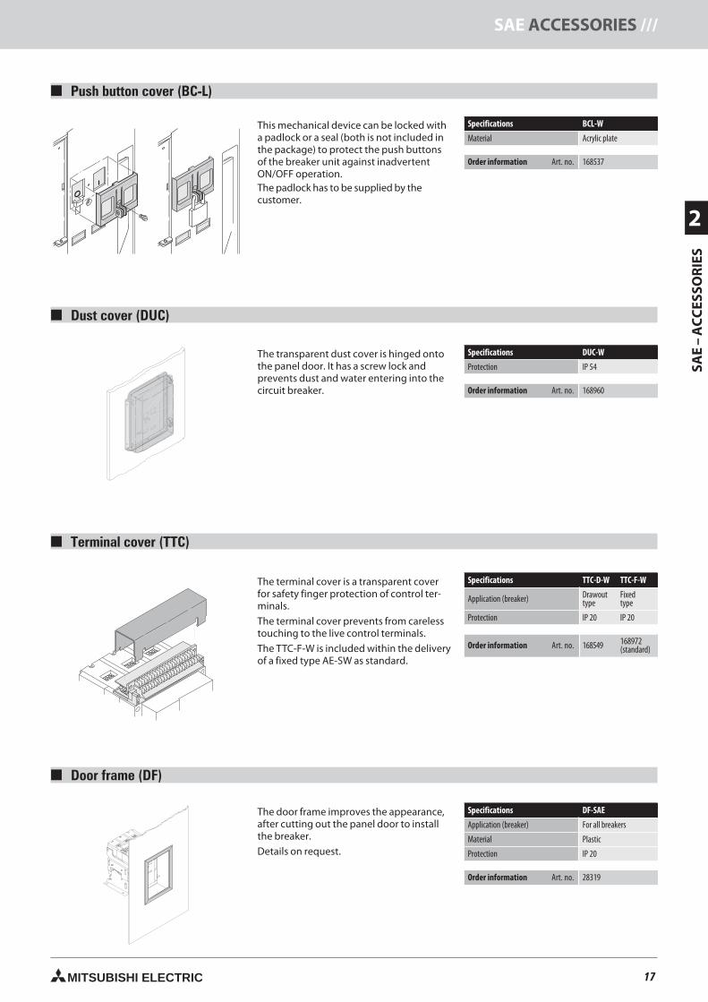
17MITSUBISHI ELECTRIC
2
SAE
–A
CC
ESSO
RIE
S
SAE ACCESSORIES ///
Push button cover (BC-L)
This mechanical device can be locked witha padlock or a seal (both is not included inthe package) to protect the push buttonsof the breaker unit against inadvertentON/OFF operation.The padlock has to be supplied by thecustomer.
Specifications BCL-W
Material Acrylic plate
Order information Art. no. 168537
Specifications DUC-W
Protection IP 54
Order information Art. no. 168960
The transparent dust cover is hinged ontothe panel door. It has a screw lock andprevents dust and water entering into thecircuit breaker.
Dust cover (DUC)
Specifications TTC-D-W TTC-F-W
Application (breaker) Drawouttype
Fixedtype
Protection IP 20 IP 20
Order information Art. no. 168549 168972(standard)
The terminal cover is a transparent coverfor safety finger protection of control ter-minals.
The terminal cover prevents from carelesstouching to the live control terminals.
The TTC-F-W is included within the deliveryof a fixed type AE-SW as standard.
Terminal cover (TTC)
Specifications DF-SAE
Application (breaker) For all breakers
Material Plastic
Protection IP 20
Order information Art. no. 28319
The door frame improves the appearance,after cutting out the panel door to installthe breaker.
Details on request.
Door frame (DF)
17neue Seiten_GB.prnLVS-Family - Technical SectionFreitag, 30. Januar 2009 14:07:46
Farbprofil: DeaktiviertKomposit Standardbildschirm
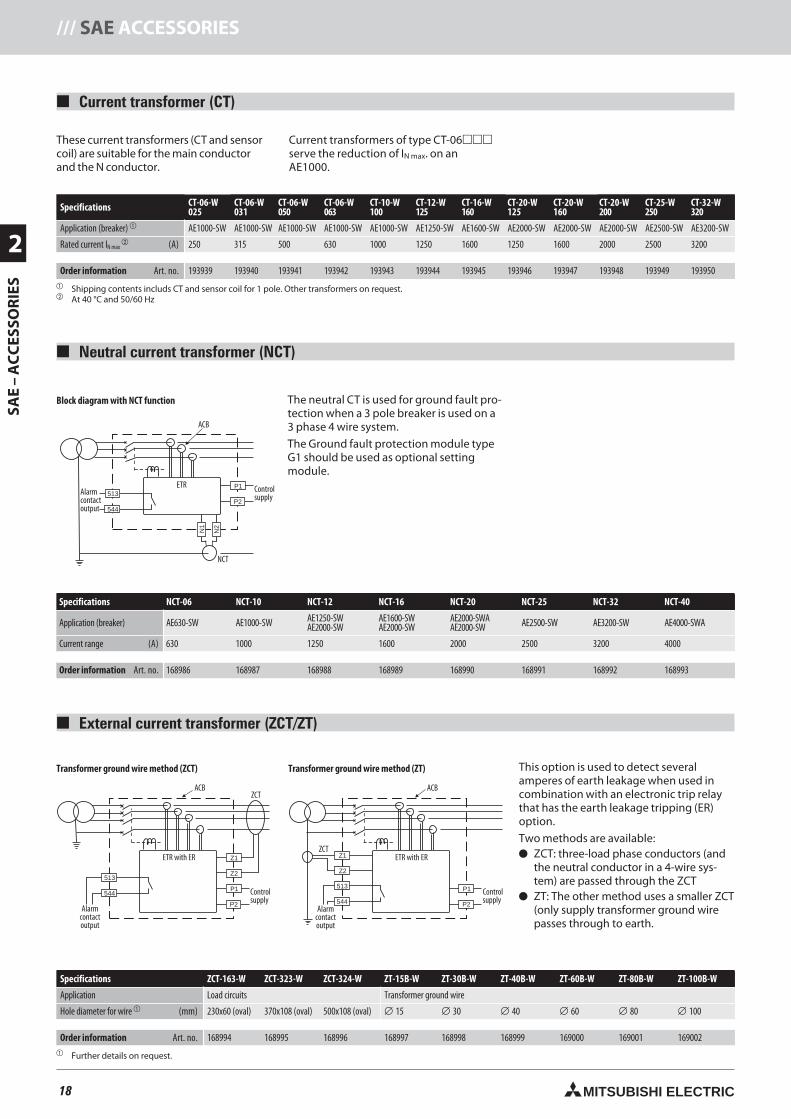
18 MITSUBISHI ELECTRIC
2
SAE
–A
CC
ESSO
RIE
S/// SAE ACCESSORIES
Current transformer (CT)
Neutral current transformer (NCT)
External current transformer (ZCT/ZT)
These current transformers (CT and sensorcoil) are suitable for the main conductorand the N conductor.
Current transformers of type CT-06serve the reduction of IN max. on anAE1000.
513
544
P1
P2
N2
N1
ACB
ETR
NCT
Alarmcontactoutput
Controlsupply
The neutral CT is used for ground fault pro-tection when a 3 pole breaker is used on a3 phase 4 wire system.
The Ground fault protection module typeG1 should be used as optional settingmodule.
Specifications NCT-06 NCT-10 NCT-12 NCT-16 NCT-20 NCT-25 NCT-32 NCT-40
Application (breaker) AE630-SW AE1000-SW AE1250-SWAE2000-SW
AE1600-SWAE2000-SW
AE2000-SWAAE2000-SW AE2500-SW AE3200-SW AE4000-SWA
Current range (A) 630 1000 1250 1600 2000 2500 3200 4000
Order information Art. no. 168986 168987 168988 168989 168990 168991 168992 168993
513
544P1
P2
ACB
ETR with ER
Alarmcontactoutput
Controlsupply
Z2
Z1
ZCT
513
544
P1
P2
ACB
ETR with ER
Alarmcontactoutput
Controlsupply
Z1
Z2
ZCT
This option is used to detect severalamperes of earth leakage when used incombination with an electronic trip relaythat has the earth leakage tripping (ER)option.
Two methods are available: three-load phase conductors (and
the neutral conductor in a 4-wire sys-tem) are passed through the ZCT
The other method uses a smaller ZCT(only supply transformer ground wirepasses through to earth.
Specifications ZCT-163-W ZCT-323-W ZCT-324-W ZT-15B-W ZT-30B-W ZT-40B-W ZT-60B-W ZT-80B-W ZT-100B-W
Application Load circuits Transformer ground wire
Hole diameter for wire (mm) 230x60 (oval) 370x108 (oval) 500x108 (oval) ∅ 15 ∅ 30 ∅ 40 ∅ 60 ∅ 80 ∅ 100
Order information Art. no. 168994 168995 168996 168997 168998 168999 169000 169001 169002 Further details on request.
Block diagram with NCT function
Transformer ground wire method (ZT)Transformer ground wire method (ZCT)
Specifications CT-06-W025
CT-06-W031
CT-06-W050
CT-06-W063
CT-10-W100
CT-12-W125
CT-16-W160
CT-20-W125
CT-20-W160
CT-20-W200
CT-25-W250
CT-32-W320
Application (breaker) AE1000-SW AE1000-SW AE1000-SW AE1000-SW AE1000-SW AE1250-SW AE1600-SW AE2000-SW AE2000-SW AE2000-SW AE2500-SW AE3200-SW
Rated current IN max (A) 250 315 500 630 1000 1250 1600 1250 1600 2000 2500 3200
Order information Art. no. 193939 193940 193941 193942 193943 193944 193945 193946 193947 193948 193949 193950 Shipping contents includs CT and sensor coil for 1 pole. Other transformers on request. At 40 °C and 50/60 Hz
18neue Seiten_GB.prnLVS-Family - Technical SectionFreitag, 30. Januar 2009 14:08:00
Farbprofil: DeaktiviertKomposit Standardbildschirm
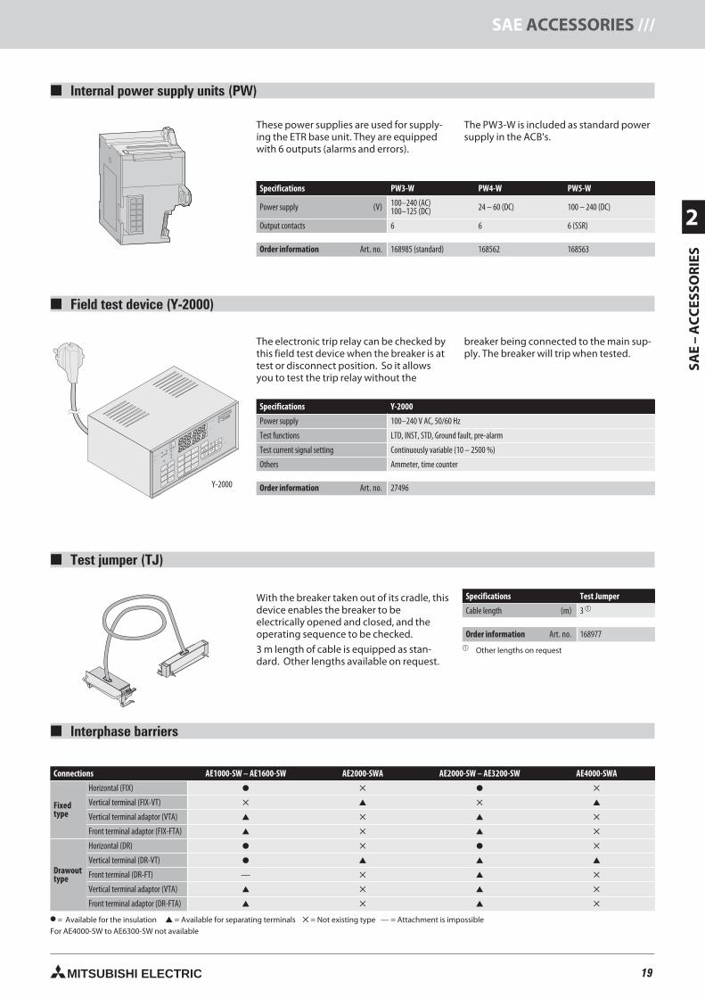
19MITSUBISHI ELECTRIC
2
SAE
–A
CC
ESSO
RIE
S
SAE ACCESSORIES ///
888.888
888.88.8
STOP
a?/OCR
VT
50/60
50 Hz60 Hz
OCR
VT
TESTING
7
4
1
0
9
6
3
SET
SIGNAL SET
SIGNAL ADJUST
STOP
SIGNAL
STOP
FREQUENCY
SIGNAL
BREAKER TESTER
UP
OPERATING
TIME
DOWN
8
5
2
?
C
OUTPUT
OUTPUT
S1S2S3
S3
S2
TC
S1
STOP
TRIP
CHECK
START
RESET
TRIP
MITSUBISHI
Y -2000
Interphase barriers
Connections AE1000-SW – AE1600-SW AE2000-SWA AE2000-SW – AE3200-SW AE4000-SWA
Fixedtype
Horizontal (FIX)
Vertical terminal (FIX-VT)
Vertical terminal adaptor (VTA)
Front terminal adaptor (FIX-FTA)
Drawouttype
Horizontal (DR)
Vertical terminal (DR-VT)
Front terminal (DR-FT) —
Vertical terminal adaptor (VTA)
Front terminal adaptor (DR-FTA)
= Available for the insulation = Available for separating terminals = Not existing type — = Attachment is impossibleFor AE4000-SW to AE6300-SW not available
Internal power supply units (PW)
Field test device (Y-2000)
Test jumper (TJ)
These power supplies are used for supply-ing the ETR base unit. They are equippedwith 6 outputs (alarms and errors).
The PW3-W is included as standard powersupply in the ACB's.
Specifications PW3-W PW4-W PW5-W
Power supply (V) 100–240 (AC)100–125 (DC) 24 – 60 (DC) 100 – 240 (DC)
Output contacts 6 6 6 (SSR)
Order information Art. no. 168985 (standard) 168562 168563
The electronic trip relay can be checked bythis field test device when the breaker is attest or disconnect position. So it allowsyou to test the trip relay without the
breaker being connected to the main sup-ply. The breaker will trip when tested.
Specifications Y-2000
Power supply 100–240 V AC, 50/60 Hz
Test functions LTD, INST, STD, Ground fault, pre-alarm
Test current signal setting Continuously variable (10 – 2500 %)
Others Ammeter, time counter
Order information Art. no. 27496
With the breaker taken out of its cradle, thisdevice enables the breaker to beelectrically opened and closed, and theoperating sequence to be checked.
3 m length of cable is equipped as stan-dard. Other lengths available on request.
Specifications Test Jumper
Cable length (m) 3
Order information Art. no. 168977 Other lengths on request
Y-2000
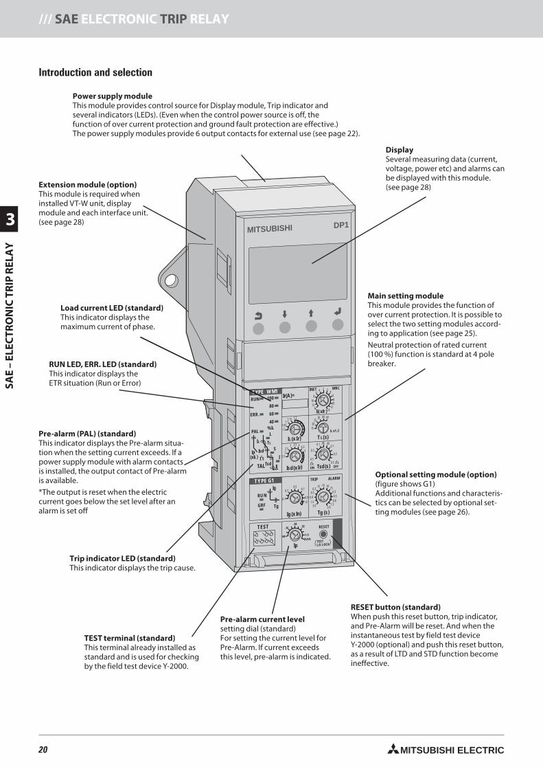
MITSUBISHI DP1
TEST
.68
.76
.84.92
OVER
1. 0
Ip
RESET
TESTL/S LOCK( )
TYPE G1
0.1
0.30.5
0.7
1.0
0.9
Ig (x In)
TRIP
3.03.0
1.51.5
0.80.8
0.50.5
0.30.3
.15.15
.10 .10
ALARM
Tg (s)
RU N
Ig
TgGRF
TYPE W M1
15
20
TL(s)
IL x1.2
2530 40 60
.06.06IL(x I
I
r
r
)
)
1.5
1.051.1
1.15 1.2
Isd (x
1.5
22.5
3 3.5 44.5
5
Ii( xIr )
INST
1010
1212
1616
88
66
44
2 2 MRC
ON OFFI2t I
2t
0.50.5
0.30.3
0.10.1
Tsd(s)
Ir(A)=RUN 100
80
60
40
%IL
ERR.
PAL
SIsd
Tsd
Ip
I2t I
Ii
(xIL)
IL TL
TAL
L
20 MITSUBISHI ELECTRIC
3
SAE
–EL
ECTR
ON
ICTR
IPR
ELA
Y/// SAE ELECTRONIC TRIP RELAY
Introduction and selection
Power supply moduleThis module provides control source for Display module, Trip indicator andseveral indicators (LEDs). (Even when the control power source is off, thefunction of over current protection and ground fault protection are effective.)The power supply modules provide 6 output contacts for external use (see page 22).
Extension module optionThis module is required wheninstalled VT-W unit, displaymodule and each interface unit.(see page 28)
RUN LED, ERR. LED (standard)indicator displays the
ETR situation (Run or Error)
DisplaySeveral measuring data (current,voltage, power etc) and alarms canbe displayed with this module.(see page 28)
Pre-alarm (PAL) (standard)This indicator displays the Pre-alarm situa-tion when the setting current exceeds. If apower supply module with alarm contactsis installed, the output contact of Pre-alarmis available.
*The output is reset when the electriccurrent goes below the set level after analarm is set off
Trip indicator LED (standard)This indicator displays the trip cause.
TEST terminal (standard)This terminal already installed asstandard and is used for checkingby the field test device Y-2000.
RESET button (standard)When push this reset button, trip indicator,and Pre-Alarm will be reset. And when theinstantaneous test by field test deviceY-2000 (optional) and push this reset button,as a result of LTD and STD function becomeineffective.
Optional setting module (option)(figure shows G1)Additional functions and characteris-tics can be selected by optional set-ting modules (see page 26).
Main setting moduleThis module provides the function ofover current protection. It is possible toselect the two setting modules accord-ing to application (see page 25).
Neutral protection of rated current(100 %) function is standard at 4 polebreaker.
Pre-alarm current levelsetting dial (standard)For setting the current level forPre-Alarm. If current exceedsthis level, pre-alarm is indicated.
Load current LED (standard)This indicator displays themaximum current of phase.
20neue Seiten_GB.prnLVS-Family - Technical SectionFreitag, 30. Januar 2009 14:08:24
Farbprofil: DeaktiviertKomposit Standardbildschirm
21MITSUBISHI ELECTRIC
SAE
–EL
ECTR
ON
ICTR
IPR
ELA
Y
3
SAE ELECTRONIC TRIP RELAY ///
Standard functions
Just under the breaker closing operation(from open to close), Instantaneouscharacteristic become effective, but afterclosing the breaker, instantaneouscharacteristic become ineffective.
When you order the MCR switch,MCR switch is built in the main body.
If MCR switch is built in the main bodyand the adjust dial of INST/MCR on main
setting module is set the MCR position,MCR function become effective(see page 27).
When it happens to trip by over current,ground fault (GFR) or Earth leakage (ER),this function issues a warning alarm.
MCR: Making current release
OCR alarm (AL)
Neutral pole overcurrent protection (NP)
When harmonics in load current are large,the current on neutral pole exceedingrated current may flow. Harmonics maycause some troubles. Neutral pole
overcurrent protection prevents themby operating at 100% of rated currenton neutral pole. Please see page 27 for50 % neutral protection.
Special Functions – Optional
NCT
Neutral CT is required for Ground faultor Neutral pole protection, when 3 polebreaker is used for 3 phase 4 wires system.(see page 18)
ZCT
ZCT is required for a few amperes earthleakage protection, and is combiningER plug. (see page 18)
21neue Seiten_GB.prnLVS-Family - Technical SectionFreitag, 30. Januar 2009 14:08:27
Farbprofil: DeaktiviertKomposit Standardbildschirm
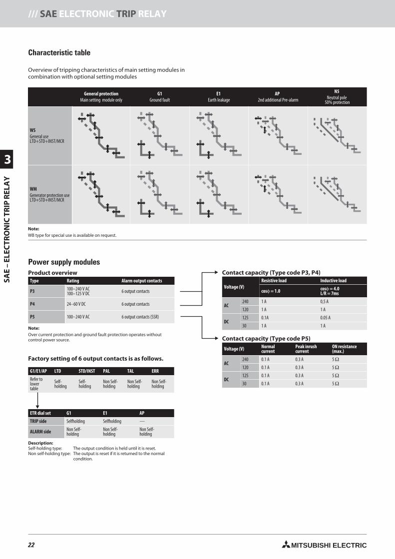
22 MITSUBISHI ELECTRIC
3
SAE
–EL
ECTR
ON
ICTR
IPR
ELA
Y/// SAE ELECTRONIC TRIP RELAY
Characteristic table
General protectionMain setting module only
G1Ground fault
E1Earth leakage
AP2nd additional Pre-alarm
N5Neutral pole
50% protection
WSGeneral useLTD+STD+INST/MCR
WMGenerator protection useLTD+STD+INST/MCR
NoteWB type for special use is available on request.
Overview of tripping characteristics of main setting modules incombination with optional setting modules
Power supply modulesProduct overview
Type Rating Alarm output contacts
P3 100–240 V AC100–125 V DC 6 output contacts
P4 24–60 V DC 6 output contacts
P5 100–240 V AC 6 output contacts (SSR)
NoteOver current protection and ground fault protection operates withoutcontrol power source.
Contact capacity (Type code P3, P4)
Voltage (V)Resistive load Inductive load
cosφ = 1.0 cosφ = 4.0L/R = 7ms
AC240 1 A 0,5 A
120 1 A 1 A
DC125 0.1A 0.05 A
30 1 A 1 A
Contact capacity (Type code P5)
Voltage (V) Normalcurrent
Peak inrushcurrent
ON resistance(max.)
AC240 0.1 A 0.3 A 5 Ω120 0.1 A 0.3 A 5 Ω
DC125 0.1 A 0.3 A 5 Ω30 0.1 A 0.3 A 5 Ω
G1/E1/AP LTD STD/INST PAL TAL ERR
Refer tolowertable
Self-holding
Self-holding
Non Self-holding
Non Self-holding
Non Self-holding
ETR dial set G1 E1 AP
TRIP side Selfholding Selfholding —
ALARM side Non Self-holding
Non Self-holding
Non Self-holding
Description:Self-holding type: The output condition is held until it is reset.Non self-holding type: The output is reset if it is returned to the normal
condition.
Factory setting of 6 output contacts is as follows.
22neue Seiten_GB.prnLVS-Family - Technical SectionFreitag, 30. Januar 2009 14:08:56
Farbprofil: DeaktiviertKomposit Standardbildschirm
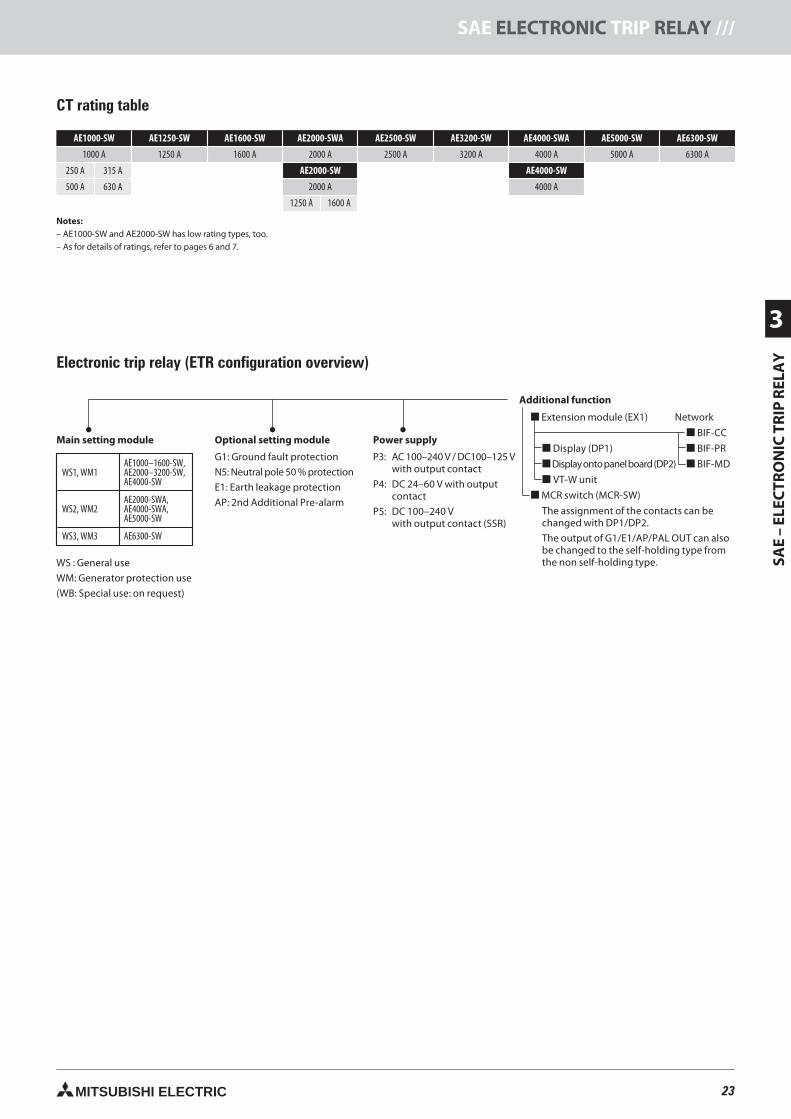
23MITSUBISHI ELECTRIC
SAE
–EL
ECTR
ON
ICTR
IPR
ELA
Y
3
SAE ELECTRONIC TRIP RELAY ///
AE1000-SW AE1250-SW AE1600-SW AE2000-SWA AE2500-SW AE3200-SW AE4000-SWA AE5000-SW AE6300-SW
1000 A 1250 A 1600 A 2000 A 2500 A 3200 A 4000 A 5000 A 6300 A
250 A 315 A AE2000-SW AE4000-SW
500 A 630 A 2000 A 4000 A
1250 A 1600 A
Notes:– AE1000-SW and AE2000-SW has low rating types, too.– As for details of ratings, refer to pages 6 and 7.
CT rating table
Electronic trip relay (ETR configuration overview)
Main setting module
WS : General use
WM: Generator protection use
(WB: Special use: on request)
Optional setting module
G1: Ground fault protection
N5: Neutral pole 50 % protection
E1: Earth leakage protection
AP: 2nd Additional Pre-alarm
Power supply
P3: AC 100–240 V / DC100–125 Vwith output contact
P4: DC 24–60 V with outputcontact
P5: DC 100–240 Vwith output contact (SSR)
WS1, WM1AE1000–1600-SW,AE2000–3200-SW,AE4000-SW
WS2, WM2AE2000-SWA,AE4000-SWA,AE5000-SW
WS3, WM3 AE6300-SW
Additional function
Extension module (EX1) Network
BIF-CC
Display (DP1) BIF-PR
Displayontopanelboard(DP2) BIF-MD
VT-W unit
MCR switch (MCR-SW)
The assignment of the contacts can bechanged with DP1/DP2.
The output of G1/E1/AP/PAL OUT can alsobe changed to the self-holding type fromthe non self-holding type.
23neue Seiten_GB.prnLVS-Family - Technical SectionFreitag, 30. Januar 2009 14:09:01
Farbprofil: DeaktiviertKomposit Standardbildschirm
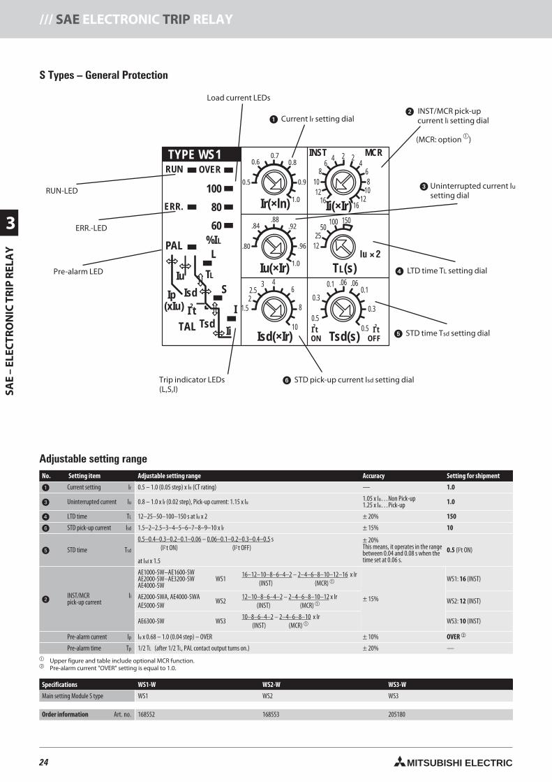
24 MITSUBISHI ELECTRIC
3
SAE
–EL
ECTR
ON
ICTR
IPR
ELA
Y/// SAE ELECTRONIC TRIP RELAY
TYPE WS1
12
25
T (s)L
Iu × 2
50100 150
.06.06
Iu( Ir)×
Isd( Ir)×
1.522.5
3 4
10
6
8
Ii(×Ir)
INST
101012
1216
16
8
8
66
44
2 2MCR
ON OFFI t2
I t2
0.5
0.5
0.3
0.3
0.10.1
Tsd(s)
RUN OVER
100
80
60
%IL
ERR.
PAL
TAL
SIsd
Tsd
Ip
I t2 I
Ii
(xIu)
Iu TL
L
0.5
.80
0.6
.84
0.7
.88
0.8
.92
1.0
1.0
0.9
.96
Ir(×ln)
S Types – General Protection
No. Setting item Adjustable setting range Accuracy Setting for shipment
Current setting Ir 0.5 – 1.0 (0.05 step) x In (CT rating) — 1.0
Uninterrupted current lu 0.8 – 1.0 x Ir (0.02 step), Pick-up current: 1.15 x Iu 1.05 x Iu…Non Pick-up1.25 x Iu…Pick-up 1.0
LTD time TL 12–25–50–100–150 s at Iu x 2 ± 20% 150
STD pick-up current Isd 1.5–2–2.5–3–4–5–6–7–8–9–10 x Ir ± 15% 10
STD time Tsd
0.5–0.4–0.3–0.2–0.1–0.06 – 0.06–0.1–0.2–0.3–0.4–0.5 s(I2 t ON) (I2 t OFF)
at Isd x 1.5
± 20%This means, it operates in the rangebetween 0.04 and 0.08 s when thetime set at 0.06 s.
0.5 (I2t ON)
INST/MCRpick-up current
Ii
AE1000-SW–AE1600-SWAE2000-SW–AE3200-SWAE4000-SW
WS116–12–10–8–6–4–2 – 2–4–6–8–10–12–16 x Ir
(INST) (MCR)
± 15%
WS1: 16 (INST)
AE2000-SWA, AE4000-SWAAE5000-SW
WS212–10–8–6–4–2 – 2–4–6–8–10–12 x Ir
(INST) (MCR) WS2: 12 (INST)
AE6300-SW WS310–8–6–4–2 – 2–4–6–8–10 x Ir
(INST) (MCR) WS3: 10 (INST)
Pre-alarm current lp Iu x 0.68 – 1.0 (0.04 step) – OVER ± 10% OVER
Pre-alarm time Tp 1/2 TL (after 1/2 TL, PAL contact output turns on.) ± 20% — Upper figure and table include optional MCR function. Pre-alarm current "OVER" setting is equal to 1.0.
Specifications WS1-W WS2-W WS3-W
Main setting Module S type WS1 WS2 WS3
Order information Art. no. 168552 168553 205180
Adjustable setting range
Load current LEDs
Current Ir setting dial
RUN-LED
ERR.-LED
Pre-alarm LED
Trip indicator LEDs(L,S,I)
STD pick-up current Isd setting dial
STD time Tsd setting dial
LTD time TL setting dial
Uninterrupted current Iusetting dial
INST/MCR pick-upcurrent Ii setting dial
(MCR: option )
24neue Seiten_GB.prnLVS-Family - Technical SectionFreitag, 30. Januar 2009 14:09:09
Farbprofil: DeaktiviertKomposit Standardbildschirm
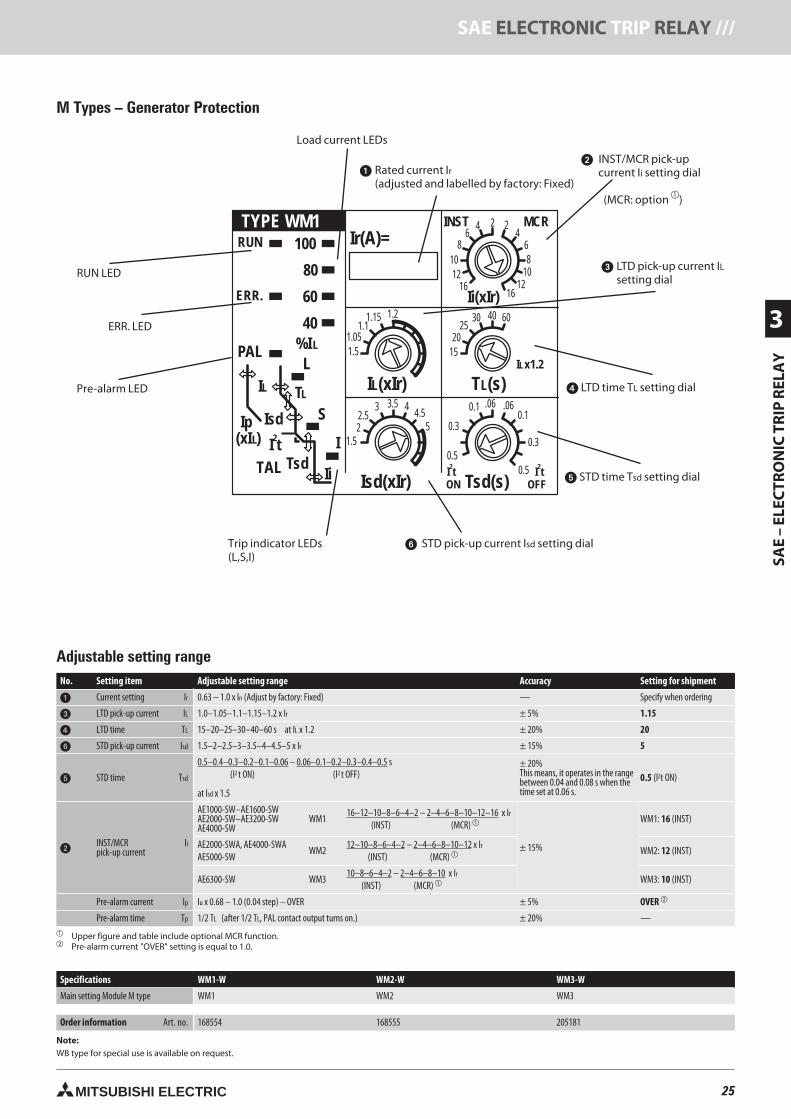
25MITSUBISHI ELECTRIC
SAE
–EL
ECTR
ON
ICTR
IPR
ELA
Y
3
SAE ELECTRONIC TRIP RELAY ///
TYPE WM1
15
20
T (s)L
I x1.2L
2530 40 60
.06.06
I (xIr)L
1.5
1.051.1
1.15 1.2
Isd(xIr)
1.522.5
3 3.5 44.5
5
Ii(xIr)
INST
101012
1216
16
8
8
66
44
2 2 MCR
ON OFFI t2
I t2
0.5
0.5
0.3
0.3
0.10.1
Tsd(s)
Ir(A)=RUN 100
80
60
40
%IL
ERR.
PAL
SIsd
Tsd
Ip
I t2 I
Ii
(xI )L
IL TL
L
TAL
M Types – Generator Protection
No. Setting item Adjustable setting range Accuracy Setting for shipment
Current setting Ir 0.63 – 1.0 x In (Adjust by factory: Fixed) — Specify when ordering
LTD pick-up current lL 1.0–1.05–1.1–1.15–1.2 x Ir ± 5% 1.15
LTD time TL 15–20–25–30–40–60 s at IL x 1.2 ± 20% 20
STD pick-up current Isd 1.5–2–2.5–3–3.5–4–4.5–5 x Ir ± 15% 5
STD time Tsd
0.5–0.4–0.3–0.2–0.1–0.06 – 0.06–0.1–0.2–0.3–0.4–0.5 s(I2 t ON) (I2 t OFF)
at Isd x 1.5
± 20%This means, it operates in the rangebetween 0.04 and 0.08 s when thetime set at 0.06 s.
0.5
INST/MCRpick-up current
Ii
AE1000-SW–AE1600-SWAE2000-SW–AE3200-SWAE4000-SW
WM116–12–10–8–6–4–2 – 2–4–6–8–10–12–16 x Ir
(INST) (MCR)
± 15%
WM1: 16 (INST)
AE2000-SWA, AE4000-SWAAE5000-SW
WM212–10–8–6–4–2 – 2–4–6–8–10–12 x Ir
(INST) (MCR) WM2: 12 (INST)
AE6300-SW WM310–8–6–4–2 – 2–4–6–8–10 x Ir
(INST) (MCR) WM3: 10 (INST)
Pre-alarm current lp Iu x 0.68 – 1.0 (0.04 step) – OVER ± 5% OVER
Pre-alarm time Tp 1/2 TL (after 1/2 TL, PAL contact output turns on.) ± 20% — Upper figure and table include optional MCR function. Pre-alarm current "OVER" setting is equal to 1.0.
Specifications WM1-W WM2-W WM3-W
Main setting Module M type WM1 WM2 WM3
Order information Art. no. 168554 168555 205181
Note:WB type for special use is available on request.
Adjustable setting range
Load current LEDs
Rated current Ir(adjusted and labelled by factory: Fixed)
RUN LED
ERR. LED
Pre-alarm LED
Trip indicator LEDs(L,S,I)
STD pick-up current Isd setting dial
STD time Tsd setting dial
LTD time TL setting dial
LTD pick-up current ILsetting dial
INST/MCR pick-upcurrent Ii setting dial
(MCR: option )
25neue Seiten_GB.prnLVS-Family - Technical SectionFreitag, 30. Januar 2009 14:09:17
Farbprofil: DeaktiviertKomposit Standardbildschirm
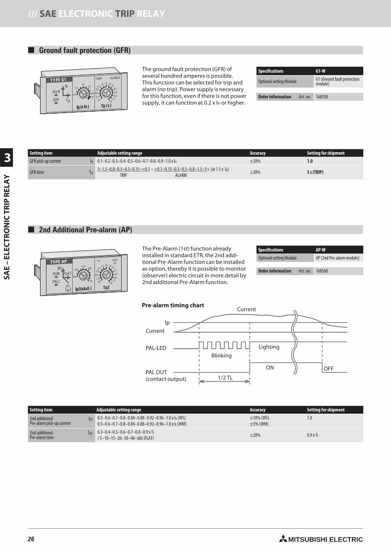
26 MITSUBISHI ELECTRIC
3
SAE
–EL
ECTR
ON
ICTR
IPR
ELA
Y/// SAE ELECTRONIC TRIP RELAY
Ground fault protection (GFR)
TYPE G1
0.1
0.30.5
0.7
1.0
0.9
Ig (x In )
TRIP
3.03.0
1.51.5
0.80.8
0.50.5
0.30.3
.15.15
.10 .10
ALARM
Tg ( s)
RU N
Ig
TgGRF
The ground fault protection (GFR) ofseveral hundred amperes is possible.This function can be selected for trip andalarm (no trip). Power supply is necessaryfor this function, even if there is not powersupply, it can function at 0.2 x In or higher.
Setting item Adjustable setting range Accuracy Setting for shipment
GFR pick-up current Ig 0.1–0.2–0.3–0.4–0.5–0.6–0.7–0.8–0.9–1.0 x In ±20% 1.0
GFR time Tg3–1.5–0.8–0.5–0.3–0.15–<0.1 – <0.1–0.15–0.3–0.5–0.8–1.5–3 s (at 1.5 x Ig)
TRIP ALARM±20% 3 s (TRIP)
Specifications G1-W
Optional setting Module G1 (Ground fault protectionmodule)
Order information Art. no. 168558
2nd Additional Pre-alarm (AP)
TYPE AP
0.6
0.680.76
0.84
1.0
Ip2(xIu/IL)
xTL
3.03.0
1.51.5
0.80.8
0.50.5
0.30.3
.15.15
.10 .10
FLAT(s)
Tp2
RUN
Ip2
FLAT
xTL
Tp 2
PAL2
The Pre-Alarm (1st) function alreadyinstalled in standard ETR, the 2nd addi-tional Pre-Alarm function can be installedas option, thereby it is possible to monitor(observer) electric circuit in more detail by2nd additional Pre-Alarm function.
Setting item Adjustable setting range Accuracy Setting for shipment
2nd additionalPre-alarm pick-up current
Ip2 0.5–0.6–0.7–0.8–0.84–0.88–0.92–0.96–1.0 x Iu (WS)0.5–0.6–0.7–0.8–0.84–0.88–0.92–0.96–1.0 x IL (WM)
±10% (WS)±5% (WM)
2nd additionalPre-alarm time
Tp2 0.3–0.4–0.5–0.6–0.7–0.8–0.9 x TL
/ 5–10–15–20–30–40–60s (FLAT)±20%
Specifications AP-W
Optional setting Module AP (2nd Pre-alarm module)
Order information Art. no. 168560
Ip
Pre-alarm timing chart
Ip
Current
PAL-LED
PAL OUT(contact output)
Blinking
Lighting
Current
ON OFF
1/2 TL
26neue Seiten_GB.prnLVS-Family - Technical SectionFreitag, 30. Januar 2009 14:09:31
Farbprofil: DeaktiviertKomposit Standardbildschirm
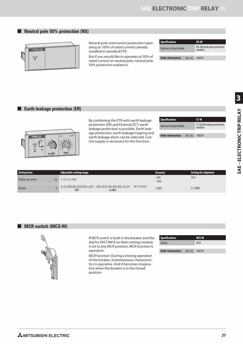
27MITSUBISHI ELECTRIC
SAE
–EL
ECTR
ON
ICTR
IPR
ELA
Y
3
SAE ELECTRONIC TRIP RELAY ///
RUN
I n∆
TeER
1
23
5 10
TYPE E1
I∆n(A)
3.03.0
1.51.5
0.80.8
0.50.5
0.30.3
.15.15
.10 .10
ALARMTRIP
Te(s)
RUN
TYPE N5
Earth leakage protection (ER)
By combining the ETR with earth leakageprotection (ER) and External ZCT, earthleakage protection is possible. Earth leak-age protection, earth leakage tripping andearth leakage alarm can be selected. Con-trol supply is necessary for this function.
Setting item Adjustable setting range Accuracy Setting for shipment
ER pick-up current In 1–2–3–5–10 A+0%–30%
10 A
ER time Te3–1.5–0.8–0.5–0.3–0.15–<0.1 – <0.1–0.15–0.3–0.5–0.8–1.5–3 s (at 1.5 x In)
TRIP ALARM±20% 3 s (TRIP)
Specifications E1-W
Optional setting Module E1 (Earth leakage protectionmodule)
Order information Art. no. 168559
MCR switch (MCS-W)
If MCR switch is built in the breaker and thedial for INST/MCR on Main setting moduleis set to any MCR position, MCR function isoperative.
MCR function: During a closing operationof the breaker, Instantaneous characteris-tics is operative. And it becomes inopera-tive when the breaker is in the closedposition.
Specifications MCS-W
Switch MCR
Order information Art. no. 168570
Neutral pole 50% protection (N5)
Neutral pole overcurrent protection (oper-ating at 100% of rated current) alreadyinstalled in standard ETR.
But if you would like to operates at 50% ofrated current on neutral pole, neutral pole50% protection realizes it.
Specifications N5-W
Optional setting Module N5 (Neutrale pole protectionmodule)
Order information Art. no. 168561
27neue Seiten_GB.prnLVS-Family - Technical SectionFreitag, 30. Januar 2009 14:10:25
Farbprofil: DeaktiviertKomposit Standardbildschirm
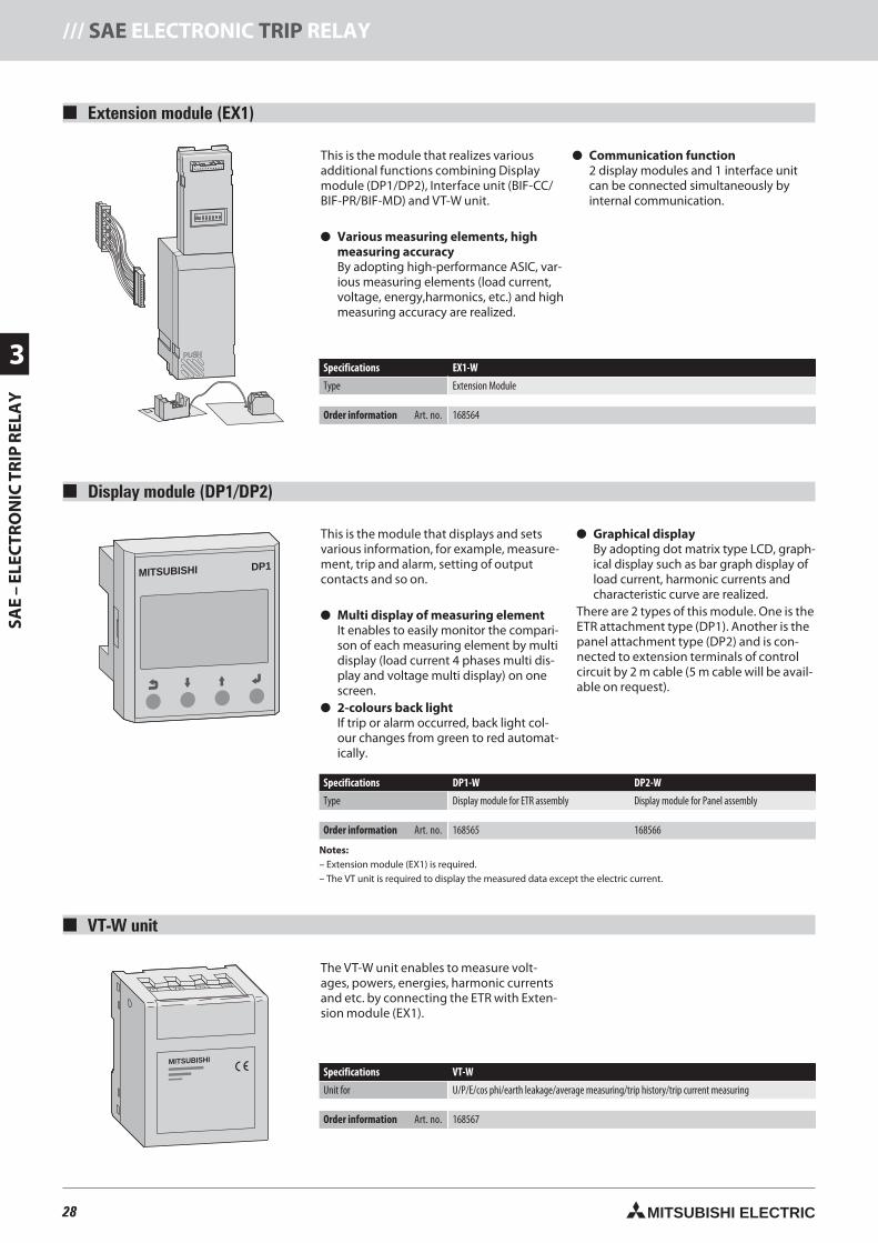
28 MITSUBISHI ELECTRIC
3
SAE
–EL
ECTR
ON
ICTR
IPR
ELA
Y/// SAE ELECTRONIC TRIP RELAY
1 2 3 4 5 6 7 8
ON
MITSUBISHI DP1
MITSUBISHI
Extension module (EX1)
This is the module that realizes variousadditional functions combining Displaymodule (DP1/DP2), Interface unit (BIF-CC/BIF-PR/BIF-MD) and VT-W unit.
Various measuring elements, highmeasuring accuracyBy adopting high-performance ASIC, var-ious measuring elements (load current,voltage, energy,harmonics, etc.) and highmeasuring accuracy are realized.
Communication function2 display modules and 1 interface unitcan be connected simultaneously byinternal communication.
Specifications EX1-W
Type Extension Module
Order information Art. no. 168564
Display module (DP1/DP2)
This is the module that displays and setsvarious information, for example, measure-ment, trip and alarm, setting of outputcontacts and so on.
Multi display of measuring elementIt enables to easily monitor the compari-son of each measuring element by multidisplay (load current 4 phases multi dis-play and voltage multi display) on onescreen.
2-colours back lightIf trip or alarm occurred, back light col-our changes from green to red automat-ically.
Graphical displayBy adopting dot matrix type LCD, graph-ical display such as bar graph display ofload current, harmonic currents andcharacteristic curve are realized.
There are 2 types of this module. One is theETR attachment type (DP1). Another is thepanel attachment type (DP2) and is con-nected to extension terminals of controlcircuit by 2 m cable (5 m cable will be avail-able on request).
Specifications DP1-W DP2-W
Type Display module for ETR assembly Display module for Panel assembly
Order information Art. no. 168565 168566
Notes:– Extension module (EX1) is required.– The VT unit is required to display the measured data except the electric current.
VT-W unit
The VT-W unit enables to measure volt-ages, powers, energies, harmonic currentsand etc. by connecting the ETR with Exten-sion module (EX1).
Specifications VT-W
Unit for U/P/E/cos phi/earth leakage/average measuring/trip history/trip current measuring
Order information Art. no. 168567
28neue Seiten_GB.prnLVS-Family - Technical SectionFreitag, 30. Januar 2009 14:11:42
Farbprofil: DeaktiviertKomposit Standardbildschirm
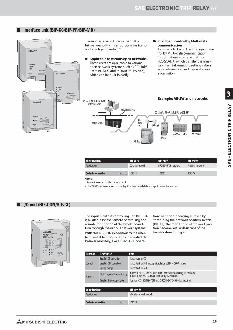
29MITSUBISHI ELECTRIC
SAE
–EL
ECTR
ON
ICTR
IPR
ELA
Y
3
SAE ELECTRONIC TRIP RELAY ///
Interface unit (BIF-CC/BIF-PR/BIF-MD)
MITSUBISHI
BUSADDRESS
ON
POWER
RESET
T ERR.
BF
These Interface units can expand thefuture possibility in variou communicationand Intelligent control.
Applicable to various open networks.These units are applicable to variousopen network systems such as CC-Link®,PROFIBUS/DP and MODBUS® (RS-485),which can be built in easily.
Intelligent control by Multi-datacommunicationIt comes into being the Intelligent con-trol by Multi-data communicationthrough these interface units toPLC/SCADA, which transfer the mea-surement information, setting values,error information and trip and alarminformation.MITSUBISHI
BUSADDRESS
ON
POWER
RESET
T ERR.
BF
MITSUBISHI
ADDRESS
ON
POWER
RESET
T ERR
RXD
TXD
Modbus
ERR.
SW
PersonalComputer
MELSECNET/10Interface card MELSECNET/10
InterfaceUnit
MDU
Eco Monitor Pro ME110S
AE-SW
PLCI/O Unit
CC-Link® / PROFIBUS-DP / MODBUS ®
By using various applicat ion softwares for PLC, users can also connect to thenetwork SCADA system.
Specifications BIF-CC-W BIF-PR-W BIF-MD-W
Application CC-Link network PROFIBUS/DP network Modbus network
Order information Art. no. 168571 168572 168573
Notes:– Extension module (EX1) is required.– The VT-W unit is required to display the measured data except the electric current.
Example: AE-SW and networksPC with MELSECNET/10-
interface card
MELSECNET/10CC-Link® / PROFIBUS/DP / MODBUS®
MELSEC PLCInter-faceunit I/O unit
AE-SWMDU
ME96NSREco Monitor Pro
I/O unit (BIF-CON/BIF-CL)
The input & output controlling unit BIF-CONis available for the remote controlling andremote monitoring of the breaker condi-tion through the various network systems.
With this BIF-CON in addition to the inter-face unit, it become possible to control thebreaker remotely, like a ON or OFF opera-
tions or Spring-charging.Further, bycombining the drawout position switch(BIF-CL), the monitoring of drawout posi-tion become available in case of thebreaker drawout type.
Function Description Note
Control
Breaker ON operation 1 a contact for CC
Breaker OFF operation 1 a contact for SHT (not applicable for AC380 – 500 V rating)
Spring charge 1 a contact for MD
MonitorDigital Input (DI) monitoring In case of BIF-CC and BIF-MD, max.3 contacts monitoring are available.
In case of BIF-PR, 1 contact monitoring is available.
Breaker drawout position Position: CONNECTED, TEST and DISCONNECTED BIF-CL is required.
Specifications BIF-CON-W
Application I/O unit network module
Order information Art. no. 168574
29neue Seiten_GB.prnLVS-Family - Technical SectionFreitag, 30. Januar 2009 14:13:12
Farbprofil: DeaktiviertKomposit Standardbildschirm
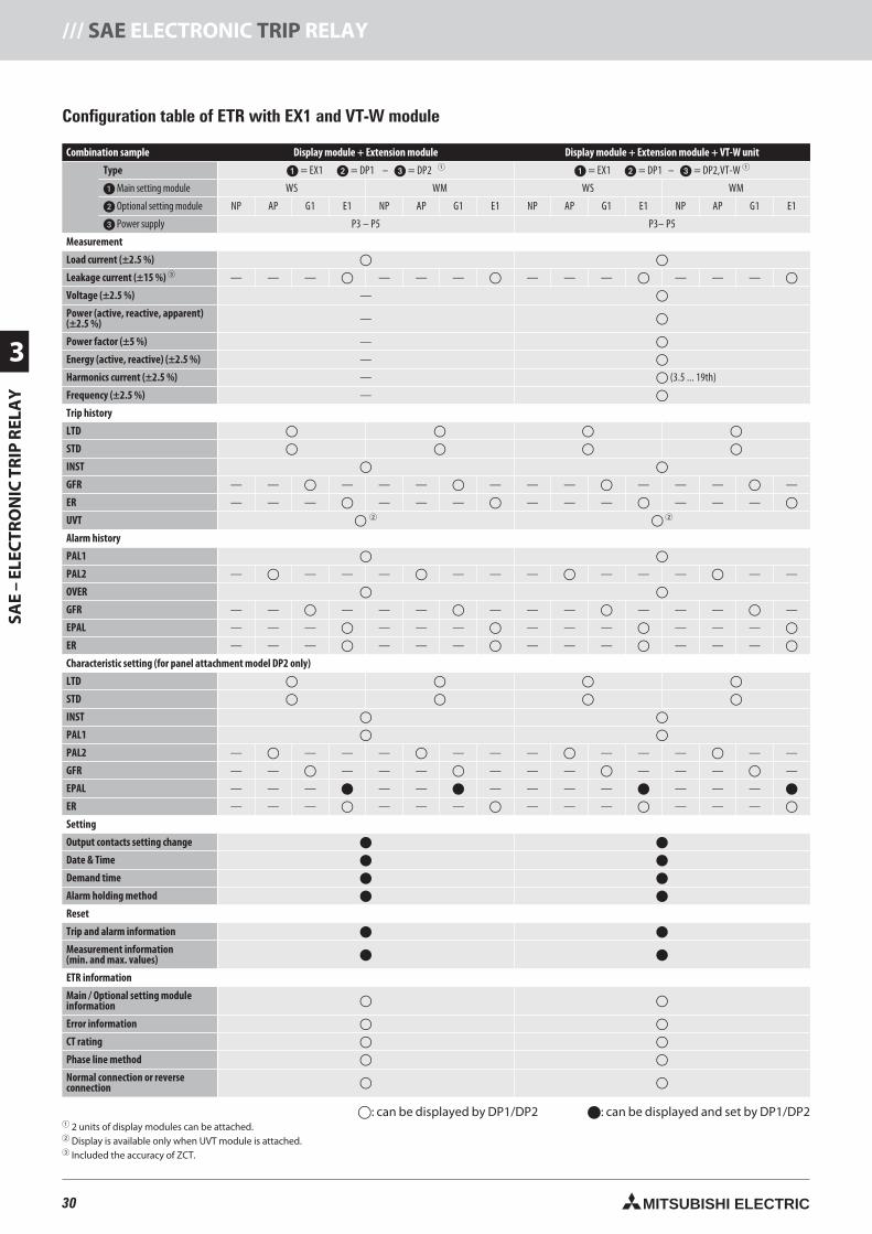
30 MITSUBISHI ELECTRIC
3
SAE
–EL
ECTR
ON
ICTR
IPR
ELA
Y/// SAE ELECTRONIC TRIP RELAY
Combination sample Display module + Extension module Display module + Extension module + VT-W unit
Type = EX1 = DP1 – = DP2 = EX1 = DP1 – = DP2,VT-W
Main setting module WS WM WS WM
Optional setting module NP AP G1 E1 NP AP G1 E1 NP AP G1 E1 NP AP G1 E1
Power supply P3 – P5 P3– P5
Measurement
Load current (±2.5 %)
Leakage current (±15 %) — — — — — — — — — — — —
Voltage (±2.5 %) —
Power (active, reactive, apparent)(±2.5 %) —
Power factor (±5 %) —
Energy (active, reactive) (±2.5 %) —
Harmonics current (±2.5 %) — (3.5 ... 19th)
Frequency (±2.5 %) —
Trip history
LTD
STD
INST
GFR — — — — — — — — — — — —
ER — — — — — — — — — — — —
UVT
Alarm history
PAL1
PAL2 — — — — — — — — — — — —
OVER
GFR — — — — — — — — — — — —
EPAL — — — — — — — — — — — —
ER — — — — — — — — — — — —
Characteristic setting (for panel attachment model DP2 only)
LTD
STD
INST
PAL1
PAL2 — — — — — — — — — — — —
GFR — — — — — — — — — — — —
EPAL — — — — — — — — — — — —
ER — — — — — — — — — — — —
Setting
Output contacts setting change
Date & Time
Demand time
Alarm holding method
Reset
Trip and alarm information
Measurement information(min. and max. values)
ETR information
Main / Optional setting moduleinformation
Error information
CT rating
Phase line method
Normal connection or reverseconnection
: can be displayed by DP1/DP2 : can be displayed and set by DP1/DP2 2 units of display modules can be attached. Display is available only when UVT module is attached. Included the accuracy of ZCT.
Configuration table of ETR with EX1 and VT-W module
30neue Seiten_GB.prnLVS-Family - Technical SectionFreitag, 30. Januar 2009 14:13:16
Farbprofil: DeaktiviertKomposit Standardbildschirm
31MITSUBISHI ELECTRIC
SAE
–EL
ECTR
ON
ICTR
IPR
ELA
Y
3
SAE ELECTRONIC TRIP RELAY ///
31neue Seiten_GB.prnLVS-Family - Technical SectionFreitag, 30. Januar 2009 14:13:20
Farbprofil: DeaktiviertKomposit Standardbildschirm
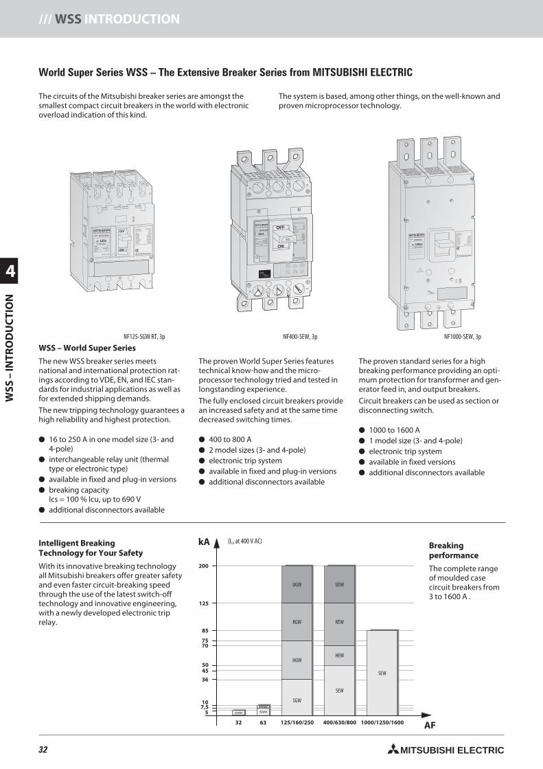
32 MITSUBISHI ELECTRIC
4
WSS
–IN
TRO
DU
CTI
ON
/// WSS INTRODUCTION
200
HW
SWSW
125
32 63
57,5
36
4550
7075
85
10
kA
AF
UGW
RGW
HGW
SGW
UEW
REW
HEW
SEW
SEW
125/160/250 400/630/800 1000/1250/1600
MITSUBISHI OFF
ON
NO-FUSE BREAKER
NF125-SGW
In A125Ir 80-125A
MODEL
POLE
Ui690V
Cat.A
PUSH TO TRIP
Uimp 8kV
3 P
IEC60947-2
JIS C 8201-2
Ue690VAC
525VAC
500VAC
440VAC
380/415VAC
230VAC
300VAC
EN60947-2
40°C
Icu/Ics
8/8kA
22/22kA
30/30kA
36/36kA
36/36kA
85/85kA
20/20kA
MITSUBISHI ELECTRIC
PAL70%50/60Hz
T
TsTL
IiIs
IrIp
Ii(X100A)
Ir(A) TL(S) IS(xIr) TS(S) Ip(xIr)
63 100 10012 22.5
10 .06.07 .10
.3 4
6
8 10
12
14
.1 .2
87
65480 3.53
60 80
OVERMODEL
RE100 In 100A
JISUe550VAC
460VAC
220VAC
IEC 60947-2
EN 60947-2
500VAC250VAC
Icn
35kA
50kA
85kA
Icu/Ics
10/10kA30/30kA42/42kA45/45kA85/85kA
40°C
50kA85kA
MITSUBISHI ELECTRIC
OFF
ON
MITSUBISHINO-FUSE BREAKER
NF400-SEP
400A
400
MODEL
POLE
Ui 690VAC
50 - 60Hz
8kV
PUSH TO TRIP
Uimp
3 P
Ip(xIr)
TEST
TL(sec) TS(sec)10012
60 80IS(xIr)
22.5
108
765300
3504
3.53
.06 .3
.1 .2Ii(X400A)
4
6
8 10
12
1614
.07 .10
Ir(A)200
220
250
400
T
TsTL
IiIs
IrIp
MITSUBISHINO-FUSE BREAKER
NF1000-SS
In A1000Ir 500-1000A
MODEL
PUSH TO TRIP
OVER
PAL
70%
IEC60947-2
EN60947-2
Ue690VAC
500VAC
440VAC
400VAC
230VAC
Cat. B
Icu/Ics
25/13kA
65/33kA
85/43kA
85/43kA
125/63kA
Icw 20kA 0.1s
MITSUBISHI ELECTRIC
4 5 67810 4
6
8 10121416
3
2
100
.06 .3
.1 .2
.7
.8 .9
1.0
60
12150
300350
250
225
200In(A)
TEST
T L(s) T S(s) IP(×In, Ir)
IS(×In, Ir ) II(×400A).5
.7 .8
1
Ir(×400A)
T
TsTL
IiIs
IrIp
World Super Series WSS – The Extensive Breaker Series from MITSUBISHI ELECTRIC
WSS – World Super Series
The new WSS breaker series meetsnational and international protection rat-ings according to VDE, EN, and IEC stan-dards for industrial applications as well asfor extended shipping demands.
The new tripping technology guarantees ahigh reliability and highest protection.
16 to 250 A in one model size (3- and4-pole)
interchangeable relay unit (thermaltype or electronic type)
available in fixed and plug-in versions breaking capacity
Ics = 100 % Icu, up to 690 V additional disconnectors available
The proven World Super Series featurestechnical know-how and the micro-processor technology tried and tested inlongstanding experience.
The fully enclosed circuit breakers providean increased safety and at the same timedecreased switching times.
400 to 800 A 2 model sizes (3- and 4-pole) electronic trip system available in fixed and plug-in versions additional disconnectors available
The proven standard series for a highbreaking performance providing an opti-mum protection for transformer and gen-erator feed in, and output breakers.
Circuit breakers can be used as section ordisconnecting switch.
1000 to 1600 A 1 model size (3- and 4-pole) electronic trip system available in fixed versions additional disconnectors available
Intelligent BreakingTechnology for Your Safety
With its innovative breaking technologyall Mitsubishi breakers offer greater safetyand even faster circuit-breaking speedthrough the use of the latest switch-offtechnology and innovative engineering,with a newly developed electronic triprelay.
The circuits of the Mitsubishi breaker series are amongst thesmallest compact circuit breakers in the world with electronicoverload indication of this kind.
The system is based, among other things, on the well-known andproven microprocessor technology.
NF125-SGW RT, 3p NF400-SEW, 3p NF1000-SEW, 3p
(ICU at 400 V AC) Breakingperformance
The complete rangeof moulded casecircuit breakers from3 to 1600 A .
32neue Seiten_GB.prnLVS-Family - Technical SectionFreitag, 30. Januar 2009 14:13:59
Farbprofil: DeaktiviertKomposit Standardbildschirm
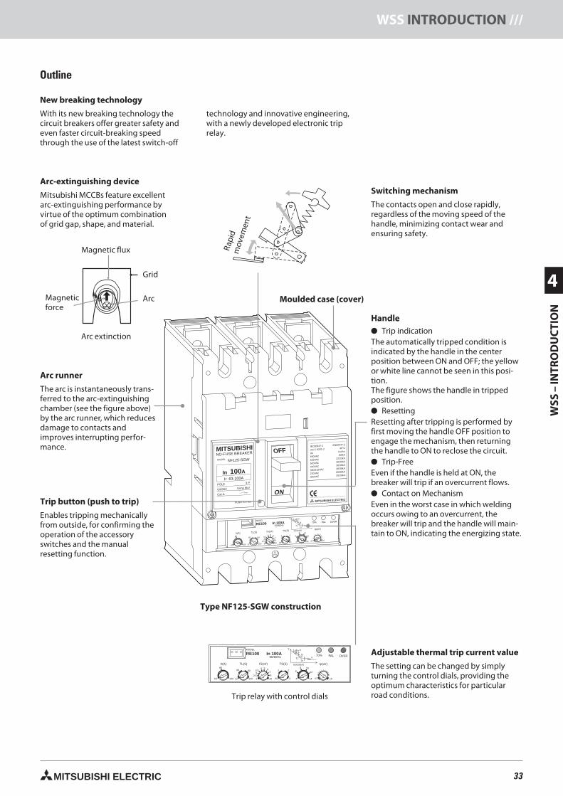
33MITSUBISHI ELECTRIC
WSS
–IN
TRO
DU
CTI
ON
4
WSS INTRODUCTION ///
MITSUBISHI OFF
ON
NO-FUSE BREAKER
NF125-SGW
In A100Ir 63-100A
MODEL
POLE
Ui690V
Cat.A
PUSH TO TRIP
Uimp 8kV
3 P
IEC60947-2
JIS C 8201-2
Ue690VAC
525VAC
500VAC
440VAC
380/415VAC
230VAC
300VAC
EN60947-2
40°C
Icu/Ics
8/8kA
22/22kA
30/30kA
36/36kA
36/36kA
85/85kA
20/20kA
MITSUBISHI ELECTRIC
PAL70%50/60Hz
T
TsTL
IiIs
IrIp
Ii(X100A)
Ir(A) TL(S) IS(xIr) TS(S) Ip(xIr)
63 100 10012 22.5
10 .06.07 .10
.3 4
6
8 10
12
14
.1 .2
87
65480 3.53
60 80
OVERMODEL
RE100 In 100A
PAL70%50/60Hz
T
TsTL Ii
Is
IrIp
Ii(X100A)Ir(A) TL(S) IS(xIr) TS(S) Ip(xIr)
63 100 10012 22.5
10 .06 .07 .10.3 4
6
8 10
12
14
.1 .2
87
654803.53
60 80
OVER
MODEL
RE100 In 100A
Trip indicationThe automatically tripped condition isindicated by the handle in the centerposition between ON and OFF; the yellowor white line cannot be seen in this posi-tion.The figure shows the handle in trippedposition. ResettingResetting after tripping is performed byfirst moving the handle OFF position toengage the mechanism, then returningthe handle to ON to reclose the circuit. Trip-FreeEven if the handle is held at ON, thebreaker will trip if an overcurrent flows. Contact on MechanismEven in the worst case in which weldingoccurs owing to an overcurrent, thebreaker will trip and the handle will main-tain to ON, indicating the energizing state.
Adjustable thermal trip current value
The setting can be changed by simplyturning the control dials, providing theoptimum characteristics for particularroad conditions.
Arc runner
The arc is instantaneously trans-ferred to the arc-extinguishingchamber (see the figure above)by the arc runner, which reducesdamage to contacts andimproves interrupting perfor-mance.
Arc-extinguishing device
Mitsubishi MCCBs feature excellentarc-extinguishing performance byvirtue of the optimum combinationof grid gap, shape, and material.
Magnetic flux
Arc extinction
Magneticforce
Switching mechanism
The contacts open and close rapidly,regardless of the moving speed of thehandle, minimizing contact wear andensuring safety.
Moulded case (cover)
Type NF125-SGW construction
Trip button (push to trip)
Enables tripping mechanicallyfrom outside, for confirming theoperation of the accessoryswitches and the manualresetting function.
Outline
New breaking technology
With its new breaking technology thecircuit breakers offer greater safety andeven faster circuit-breaking speedthrough the use of the latest switch-off
technology and innovative engineering,with a newly developed electronic triprelay.
Trip relay with control dials
Grid
Arc
Rapi
dm
ovem
ent
33neue Seiten_GB.prnLVS-Family - Technical SectionFreitag, 30. Januar 2009 14:14:23
Farbprofil: DeaktiviertKomposit Standardbildschirm
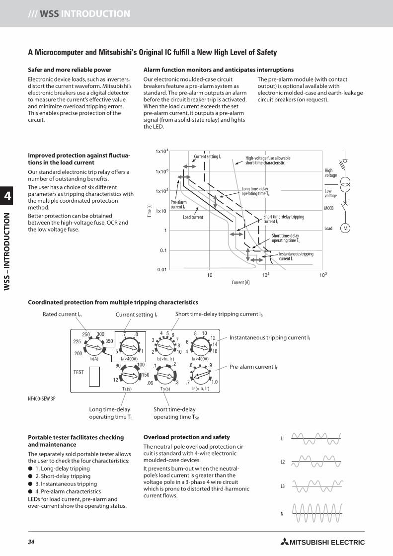
34 MITSUBISHI ELECTRIC
4
WSS
–IN
TRO
DU
CTI
ON
/// WSS INTRODUCTION
4 5 67810 4
6
8 10121416
3
2
100
.06 .3
.1 .2
.7
.8 .9
1.0
60
12150
300350
250225
200In(A)
TEST
T L(s) T S(s) IP(×In, Ir)
IS(×In, Ir ) II(×400A)
.5
.7 .8
1Ir(×400A)
L1
L2
L3
N
A Microcomputer and Mitsubishi’s Original IC fulfill a New High Level of Safety
Safer and more reliable power
Electronic device loads, such as inverters,distort the current waveform. Mitsubishi’selectronic breakers use a digital detectorto measure the current’s effective valueand minimize overload tripping errors.This enables precise protection of thecircuit.
Overload protection and safety
The neutral-pole overload protection cir-cuit is standard with 4-wire electronicmoulded-case devices.
It prevents burn-out when the neutral-pole’s load current is greater than thevoltage pole in a 3-phase 4 wire circuitwhich is prone to distorted third-harmoniccurrent flows.
Time[
s]
Current [A]
Current setting Ir
Pre-alarmcurrent IP
Load current
Instantaneous trippingcurrent II
Short time-delayoperating time TS
Short time-delay trippingcurrent IS
Long time-delayoperating time TL
High-voltage fuse allowableshort-time characteristic
Highvoltage
Lowvoltage
MCCB
Load
Alarm function monitors and anticipates interruptions
Our electronic moulded-case circuitbreakers feature a pre-alarm system asstandard. The pre-alarm outputs an alarmbefore the circuit breaker trip is activated.When the load current exceeds the setpre-alarm current, it outputs a pre-alarmsignal (from a solid-state relay) and lightsthe LED.
The pre-alarm module (with contactoutput) is optional available withelectronic molded-case and earth-leakagecircuit breakers (on request).
Improved protection against fluctua-tions in the load current
Our standard electronic trip relay offers anumber of outstanding benefits.
The user has a choice of six differentparameters as tripping characteristics withthe multiple coordinated protectionmethod.
Better protection can be obtainedbetween the high-voltage fuse, OCR andthe low voltage fuse.
Portable tester facilitates checkingand maintenance
The separately sold portable tester allowsthe user to check the four characteristics: 1. Long-delay tripping 2. Short-delay tripping 3. Instantaneous tripping 4. Pre-alarm characteristicsLEDs for load current, pre-alarm andover-current show the operating status.
Coordinated protection from multiple tripping characteristics
Rated current In
NF400-SEW 3P
Short time-delayoperating time TSd
Pre-alarm current IP
Instantaneous tripping current II
Long time-delayoperating time TL
Short time-delay tripping current ISCurrent setting Ir
34neue Seiten_GB.prnLVS-Family - Technical SectionFreitag, 30. Januar 2009 14:14:39
Farbprofil: DeaktiviertKomposit Standardbildschirm
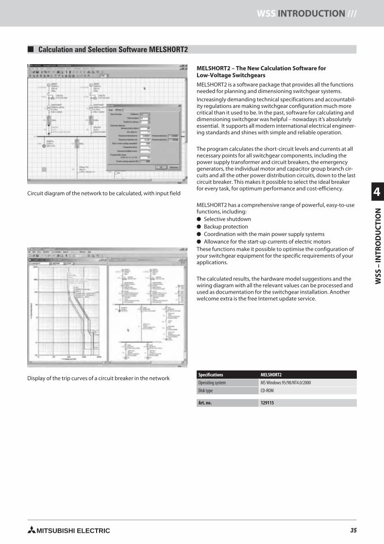
35MITSUBISHI ELECTRIC
WSS
–IN
TRO
DU
CTI
ON
4
WSS INTRODUCTION ///
Calculation and Selection Software MELSHORT2
MELSHORT2 – The New Calculation Software forLow-Voltage Switchgears
MELSHORT2 is a software package that provides all the functionsneeded for planning and dimensioning switchgear systems.
Increasingly demanding technical specifications and accountabil-ity regulations are making switchgear configuration much morecritical than it used to be. In the past, software for calculating anddimensioning switchgear was helpful – nowadays it’s absolutelyessential. It supports all modern international electrical engineer-ing standards and shines with simple and reliable operation.
The program calculates the short-circuit levels and currents at allnecessary points for all switchgear components, including thepower supply transformer and circuit breakers, the emergencygenerators, the individual motor and capacitor group branch cir-cuits and all the other power distribution circuits, down to the lastcircuit breaker. This makes it possible to select the ideal breakerfor every task, for optimum performance and cost-efficiency.
MELSHORT2 has a comprehensive range of powerful, easy-to-usefunctions, including: Selective shutdown Backup protection Coordination with the main power supply systems Allowance for the start-up currents of electric motorsThese functions make it possible to optimise the configuration ofyour switchgear equipment for the specific requirements of yourapplications.
The calculated results, the hardware model suggestions and thewiring diagram with all the relevant values can be processed andused as documentation for the switchgear installation. Anotherwelcome extra is the free Internet update service.
Specifications MELSHORT2
Operating system MS Windows 95/98/NT4.0/2000
Disk type CD-ROM
Art. no. 129115
35neue Seiten_GB.prnLVS-Family - Technical SectionFreitag, 30. Januar 2009 14:14:45
Farbprofil: DeaktiviertKomposit Standardbildschirm
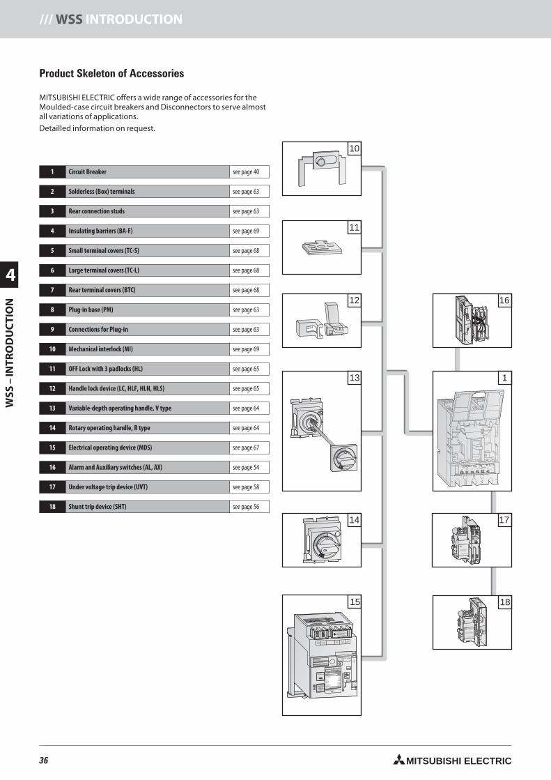
36 MITSUBISHI ELECTRIC
4
WSS
–IN
TRO
DU
CTI
ON
/// WSS INTRODUCTION
Product Skeleton of Accessories
MITSUBISHI ELECTRIC offers a wide range of accessories for theMoulded-case circuit breakers and Disconnectors to serve almostall variations of applications.
Detailled information on request.
1 Circuit Breaker see page 40
2 Solderless (Box) terminals see page 63
3 Rear connection studs see page 63
4 Insulating barriers (BA-F) see page 69
5 Small terminal covers (TC-S) see page 68
6 Large terminal covers (TC-L) see page 68
7 Rear terminal covers (BTC) see page 68
8 Plug-in base (PM) see page 63
9 Connections for Plug-in see page 63
10 Mechanical interlock (MI) see page 69
11 OFF Lock with 3 padlocks (HL) see page 65
12 Handle lock device (LC, HLF, HLN, HLS) see page 65
13 Variable-depth operating handle, V type see page 64
14 Rotary operating handle, R type see page 64
15 Electrical operating device (MDS) see page 67
16 Alarm and Auxiliary switches (AL, AX) see page 54
17 Under voltage trip device (UVT) see page 58
18 Shunt trip device (SHT) see page 56
1
12
11
10
15
14
RESET
OFF
TRIP
PED
PUSHTOTRIP
ON
AC100-240V50/60Hz
Install and uninstall the
accessory in tripped position,
not in ON or OFF position
SHTA240-2GSWRS
C2
S2
C1
S1
SH
T
18
D1
P1
D3
P3
D2
P2
SO
UR
CE
Hi
Lo
17
16
ALAX-2GSWLS
MITSUBISHIELECTRIC
AL
95 c14 a
96 b12 b
98 a11 c
AX
ALA
RM
SW
ITC
HA
CA
CD
CD
C
125V
250V
125V
250V
5A
3A
0.4
A0.2
A98
ALa
96
ALb
98
ALc
AU
XIL
IAR
YS
WIT
CH
AC
AC
DC
DC
125V
250V
125V
250V
5A
3A
0.4
A0.2
A11
AX
c12
AX
b14
AX
a
Push to
(MANU)
NO-FUSE BREAKER
NF250-SGW
MSDBA-NF25GSW
A0106
MODEL
Push
Pull
MODEL
SERIAL:
Ui 690V
Cat.A
IEC60947-2
JIS C 8201-2
Ue690VAC
525VAC
500VAC
440VAC
380/415VAC
230VAC
MANU
AUTO
RATED CURRENT
250 A
Uimp 8kV
EN60947-2
40°C
Icu/Ics
8/8kA
22/22kA
30/30kA
36/36kA
36/36kA
85/85kA
50/60Hz
Push toOPEN
(TRIP)
ON
MITSUBISHI ELECTRIC
ON
Dis-charge
Control circuitvoltage should besupplied to P1and P2 terminals.
P1 P2 S1 S2 S4
MITSUBISHIPOWER SUPPLY MODULE
MODEL MDSPSA240-SW
CONTROLL CIRCUIT VOLTAGE
AC100-240V/DC100-250V
S4OperatingCircuit S2
P2S1
P1
P1P2S1S2S4
Uc
Uc
ON
K3
K2
K2
K1K1
SW1K3
K3
K2
K1
PowerSupply
OFF
13
RESET
OFF
TRIP
PED
PUSHTOTRIP
ON
63 100 10012 22.5
10 .06.07 .10
.3 4
6
8 10
12
14
.1 .2
87
65480 3.53
60 80
PAL70%50/60Hz
T
TsTL
IiIs
IrIp
Ii(X100A)
Ir(A) TL(S) IS(xIr) TS(S) Ip(xIr)
OVERMODEL
RE100 In 100A
Install and uninstall the
accessory in tripped position,
not in ON or OFF position
UVTSA250-2GSWRS
36neue Seiten_GB.prnLVS-Family - Technical SectionFreitag, 30. Januar 2009 14:15:35
Farbprofil: DeaktiviertKomposit Standardbildschirm
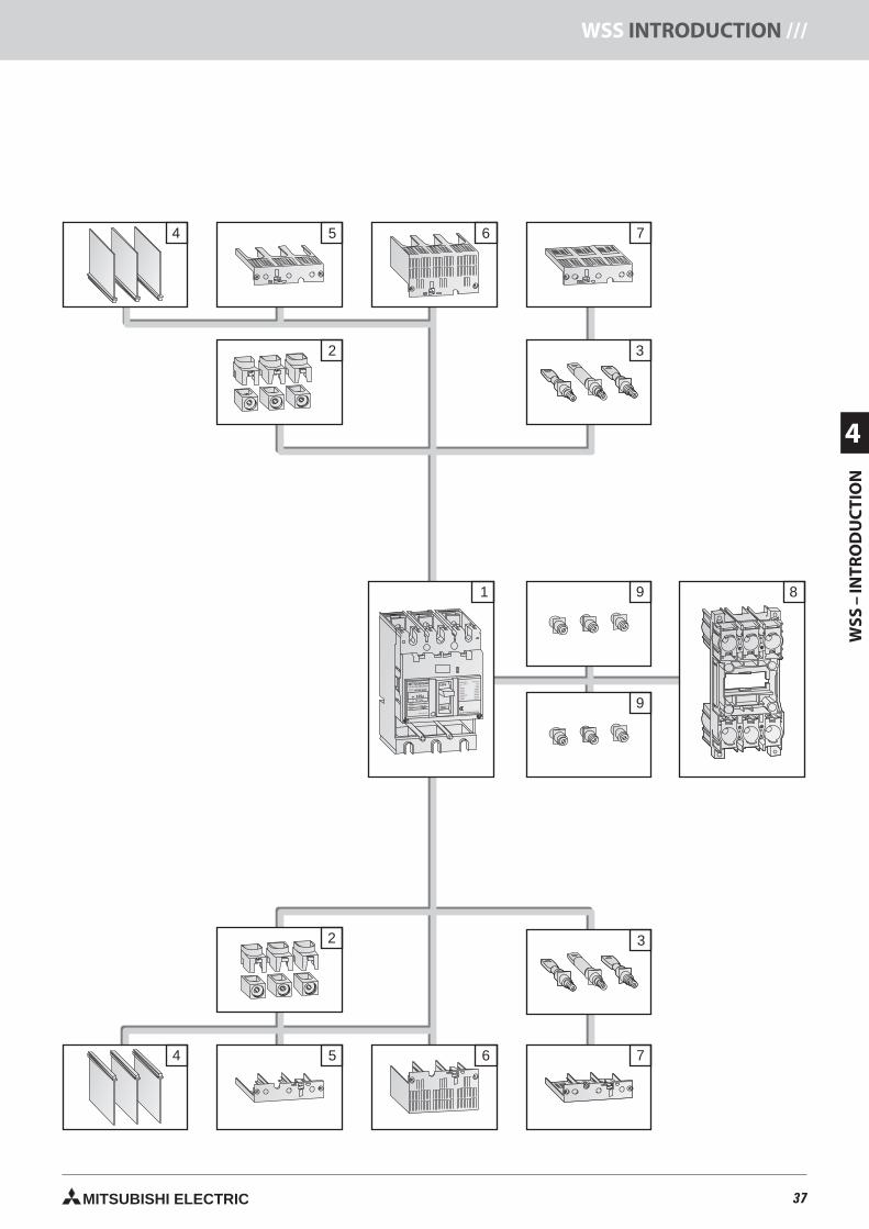
37MITSUBISHI ELECTRIC
WSS
–IN
TRO
DU
CTI
ON
4
WSS INTRODUCTION ///
4 65 7
3
65 7
2 3
4
2
9
9
1
MITSUBISHI OFF
ON
NO-FUSE BREAKER
NF125-SGW
In A125Ir 75-125A
MODEL
POLE
Ui690V
Cat.A
PUSH TO TRIP
Uimp 8kV
3 P
IEC60947-2
JIS C 8201-2
Ue690VAC
525VAC
500VAC
440VAC
380/415VAC
230VAC
300VAC
EN60947-2
40°C
Icu/Ics
8/8kA
22/22kA
30/30kA
36/36kA
36/36kA
85/85kA
20/20kA
MITSUBISHI ELECTRIC
8
37neue Seiten_GB.prnLVS-Family - Technical SectionFreitag, 30. Januar 2009 14:15:49
Farbprofil: DeaktiviertKomposit Standardbildschirm
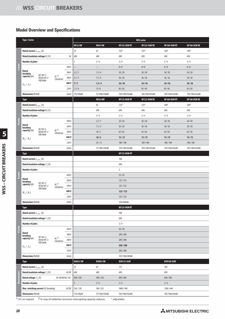
38 MITSUBISHI ELECTRIC
5
WSS
–C
IRC
UIT
BR
EAK
ERS
/// WSS CIRCUIT BREAKERS
Type / Series WSS series
NF32-SW NF63-SW NF125-SGW RT NF125-SGW RE NF160-SGW RT NF160-SGW RE
Sser
ies
Rated current In max. [A] 32 63 125* 125* 160* 160*
Rated insulation voltage Ui [V] AC 600 600 690 690 690 690
Number of poles 3 3 / 4 3 / 4 3 / 4 3 / 4 3 / 4
Ratedbreakingcapacity [kA]
(Icu / Ics)
IEC 947-2EN 60 947-2VDE 0660
AC
(50/60 Hz)
690 V — — 8 / 8 8 / 8 8 / 8 8 / 8
500 V 2.5 / 1 7.5 / 4 30 / 30 30 / 30 30 / 30 30 / 30
440 V 2.5 / 1 7.5 / 4 36 / 36 36 / 36 36 / 36 36 / 36
400 V 5 / 2 7.5 / 4 36 / 36 36 / 36 36 / 36 36 / 36
230 V 7.5 / 4 15 / 8 85 / 85 85 / 85 85 / 85 85 / 85
Dimensions WxHxD [mm] 75x130x68 75/100x130x68 105/140x165x86 105/140x165x86 105/140x165x86 105/140x165x86
Type NF63-HW NF125-HGW RT NF125-HGW RE NF160-HGW RT NF160-HGW RE
Hse
ries
In max. [A] 63 125* 125* 160* 160*
Ui [V] 690 690 690 690 690
3 / 4 3 / 4 3 / 4 3 / 4 3 / 4
[kA]
(Icu / Ics)
IEC 947-2EN 60 947-2VDE 0660
AC
(50/60 Hz)
690 V 2.5 / 1 20 / 20 20 / 20 20 / 20 20 / 20
500 V 7.5 / 4 50 / 50 50 / 50 50 / 50 50 / 50
440 V 10 / 5 65 / 65 65 / 65 65 / 65 65 / 65
400 V 10 / 5 75 / 75 75 / 75 75 / 75 75 / 75
230 V 25 / 13 100 / 100 100 / 100 100 / 100 100 / 100
WxHxD [mm] 75/100x130x68 105/140x165x86 105/140x165x86 105/140x165x86 105/140x165x86
Type NF125-RGW RT
Rse
ries
Rated current In max. [A] 100
Rated insulation voltage Ui [V] 690
Number of poles 3
[kA]
(Icu / Ics)
IEC 947-2EN 60 947-2VDE 0660
AC
(50/60 Hz)
690 V 25 / 25
500 V 125 / 125
440 V 125 / 125
400 V 125 / 125
230 V 125 / 125
Dimensions WxHxD [mm] 105x240x86
Type NF125-UGW RT
Use
ries
Rated current In max. [A] 100
Rated insulation voltage Ui [V] 690
Number of poles 3 / 4
Ratedbreakingcapacity [kA]
(Icu / Ics)
IEC 947-2EN 60 947-2VDE 0660
AC
(50/60 Hz)
690 V 30 / 30
500 V 200 / 200
440 V 200 / 200
400 V 200 / 200
230 V 200 / 200
Dimensions WxHxD [mm] 105/140x240x86
Type DSN32-SW DSN63-SW DSN125-SGW DSN160-SGW
Disc
onne
ctor
s
Rated current In max. [A] 32 63 125 160
Rated insulation voltage Ui [V] AC/DC 600 600 690 690
Rated voltage Ue [V] AC (50/60 Hz) / DC 500 / 250 500 / 250 690 / 300 690 / 300
3 3 / 4 3 / 4 3 / 4
Max. switching current [A] (breaking) AC/DC 256 / 128 504 / 252 1000 / 500 1280 / 640
Dimensions WxHxD 75x130x68 75/120x130x68 105/140x165x86 105/140x165x86
DC on request In case of solderless terminal, interrupting capacity reduces. * adjustable
Model Overview and Specifications
38neue Seiten_GB.prnLVS-Family - Technical SectionFreitag, 30. Januar 2009 14:15:56
Farbprofil: DeaktiviertKomposit Standardbildschirm
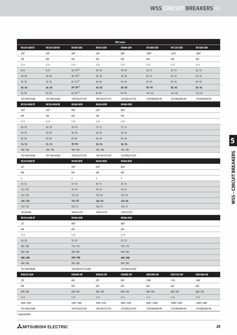
39MITSUBISHI ELECTRIC
WSS
–C
IRC
UIT
BR
EAK
ERS
5
WSS CIRCUIT BREAKERS ///
WSS series
NF250-SGW RT NF250-SGW RE NF400-SEW NF630-SEW NF800-SEW NF1000-SEW NF1250-SEW NF1600-SEW
250* 250* 400* 630* 800* 1000* 1250* 1600*
690 690 690 690 690 690 690 690
3 / 4 3 / 4 3 / 4 3 / 4 3 / 4 3 / 4 3 / 4 3 / 4
8 / 8 8 / 8 10 / 10 10 / 10 10 / 10 25 / 13 25 / 13 25 / 13
30 / 30 30 / 30 30 / 30 30 / 30 30 / 30 65 / 33 65 / 33 65 / 33
36 / 36 36 / 36 42 / 42 42 / 42 42 / 42 85 / 43 85 / 43 85 / 43
36 / 36 36 / 36 50 / 50 50 / 50 50 / 50 85 / 43 85 / 43 85 / 43
85 / 85 85 / 85 85 / 85 85 / 85 85 / 85 125 / 63 125 / 63 125 / 63
105/140x165x86 105/140x165x86 140/185x257x103 140/185x257x103 210/280x275x103 210/280x406x140 210/280x406x140 210/280x406x140
NF250-HGW RT NF250-HGW RE NF400-HEW NF630-HEW NF800-HEW
250* 250* 400* 630* 800*
690 690 690 690 690
3 / 4 3 / 4 3 / 4 3 / 4 3 / 4
20 / 20 20 / 20 10 / 10 15 / 15 15 / 15
50 / 50 50 / 50 50 / 50 50 / 50 50 / 50
65 / 65 65 / 65 65 / 65 65 / 65 65 / 65
75 / 75 75 / 75 70 / 70 70 / 70 70 / 70
100 / 100 100 / 100 100 / 100 100 / 100 100 / 100
105/140x165x86 105/140x165x86 140/185x257x103 140/185x257x103 210/280x275x103
NF250-RGW RT NF400-REW NF630-REW NF800-REW
225 400* 630* 800*
690 690 690 690
3 3 3 3
25 / 25 15 / 10 20 / 15 20 / 15
125 / 125 70 / 35 70 / 35 70 / 35
125 / 125 125 / 63 125 / 63 125 / 63
125 / 125 125 / 63 125 / 63 125 / 63
125 / 125 150 / 75 150 / 75 150 / 75
105x240x86 140x257x103 140x257x103 210x275x103
NF250-UGW RT NF400-UEW NF800-UEW
225 400* 800*
690 690 690
3 / 4 3 / 4 3 / 4
30 / 30 35 / 35 35 / 35
200 / 200 170 / 170 170 / 170
200 / 200 200 / 200 200 / 200
200 / 200 200 / 200 200 / 200
200 / 200 200 / 200 200 / 200
105/140x240x86 140/280x297/322x200 210/280x322x200
DSN250-SGW DSN400-SW DSN630-SW DSN800-SW DSN1000-SW DSN1250-SW DSN1600-SW
250 400 630 800 1000 1250 1600
690 690 690 690 660 660 660
690 / 300 690 / 250 690 / 250 690 / 250 660 / 250 660 / 250 660 / 250
3 / 4 3 / 4 3 / 4 3 / 4 3 / 4 3 / 4 3 / 4
2000 / 1000 3200 / 1600 5040 / 2520 6400 / 3200 8000 / 14000 10000 / 5000 12800 / 6400
105/140x165x86 140/185x257x103 140/185x257x103 210/280x275x103 210/280x406x140 210/280x406x140 210/280x406x140
* adjustable
39neue Seiten_GB.prnLVS-Family - Technical SectionFreitag, 30. Januar 2009 14:16:00
Farbprofil: DeaktiviertKomposit Standardbildschirm
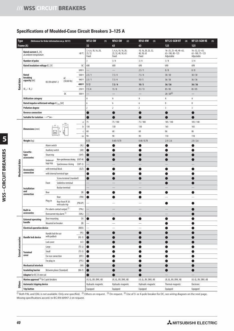
40 MITSUBISHI ELECTRIC
5
WSS
–C
IRC
UIT
BR
EAK
ERS
/// WSS CIRCUIT BREAKERS
Type (Reference for Order information on p. 50/51) NF32-SW (1) NF63-SW (2) NF63-HW (3) NF125-SGW RT (4) NF125-SGW RE (5)
Frame (A) 32 63 63 125 125
Rated current In [A]at ambient temperature 40 °C
3, 4, 6, 10, 16, 20,25, 32Fixed
3, 4, 6, 10, 16, 20,25, 32, 40, 50, 63Fixed
10, 16, 20, 25, 32,40, 50, 63Fixed
16–25, 25–40, 40–63,63–100, 80–125Adjustable
16–32, 32–63,63–100, 75–125Adjustable
Number of poles 3 3 / 4 3 / 4 3 / 4 3 / 4
Rated insulation voltage Ui [V] AC 600 600 690 690 690
Ratedbreakingcapacity [kA]
(Icu / Ics)
IEC/EN 60947-2AC(50/60 Hz)
690 V — — 2.5 / 1 8 / 8 8 / 8
500 V 2.5 / 1 7.5 / 4 7.5 / 4 30 / 30 30 / 30
440 V 2.5 / 1 7.5 / 4 10 / 5 36 / 36 36 / 36
400 V 5 / 2 7.5 / 4 10 / 5 36 / 36 36 / 36
230 V 7.5 /4 15 / 8 25 / 13 85 / 85 85 / 85
DC 300 V — — — 20 / 20 —
Utilization category A A A A A
Rated impulse withstand voltage Uimp [kV] 6 6 6 8 8
Pollution degree 2 2 2 3 3
Reverse connection
Suitable for isolation
Dimensions [mm]
a 75 75 / 100 75 / 100 105 / 140 105 / 140
b 130 130 130 165 165
c 68 68 68 86 86
ca 90 90 90 110 110
Weight [kg] 0.55 0.60 / 0.70 0.60 / 0.70 2.0 / 2.6 2.0 / 2.6
Cassette-typeaccessories
Alarm switch (AL)
Auxiliary switch (AX)
Shunt trip (SHT)
Undervol-tage trip
Non-synchronousclosing (UVT-N)
Synchronous closing (UVT-S) — — — — —
Accessoriesconnection
with terminal block (SLT)
with internal terminal type
Front
Screw terminal (standard)
Solderless terminal — — —
Busbar terminal — — — — —
Rear (B)
Plug-inRear (PM) — —
Rear front IP 20with auto trip (PM-IP) — — —
Built-inaccessories
Pre-alarm-contact output (PAL) — — — —
Overcurrent trip alarm (OAL) — — — —
External operatinghandle
Door mounting (V)
Mounted on breaker (R) — — —
Electrical operation device (MDS) — — —
Handle lock deviceHandle lock for usewith padlock
(HL)
(HL-S)
Lock cover (LC)
Terminalcover
Large (TC-L)
Small (TC-S)
For rear connection (BTC)
For plug-in (PTC)
Mechanical interlock (MI)
Insulating barrier Between phase (Standard) (BA-F)
Adapter for IEC 35 mm rail — —
Marine approval for 3 pole breakers LR, GL, BV, DNV, AB LR, GL, BV, DNV, AB LR, GL, BV, DNV, AB LR, GL, BV, DNV, AB LR, GL, BV, DNV, AB
Automatic tripping device Hydraulic-magnetic Hydraulic-magnetic Hydraulic-magnetic Thermal-magnetic Electronic
Trip button Equipped Equipped Equipped Equipped Equipped
Both PAL and OAL is not available. Only one specified. Others on request. On request. Use of 3- or 4-pole breaker for DC, see wiring diagram on the next page.Missing specifications accord. to IEC/EN 60947-2 on request.
Silke
Specifications of Moulded-Case Circuit Breakers 3–125 A
a
b
cca
Rate
dda
taM
echa
nica
ldat
aEx
tern
lacc
esso
ries
Othe
rs
40neue Seiten_GB.prnLVS-Family - Technical SectionFreitag, 30. Januar 2009 14:16:11
Farbprofil: DeaktiviertKomposit Standardbildschirm
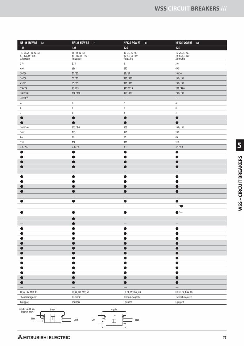
41MITSUBISHI ELECTRIC
WSS
–C
IRC
UIT
BR
EAK
ERS
5
WSS CIRCUIT BREAKERS ///
NF125-HGW RT (6) NF125-HGW RE (7) NF125-RGW RT (8) NF125-UGW RT (9)
125 125 125 125
16–25, 25–40, 40–63,63–100, 80–125Adjustable
16–32, 32–63,63–100, 75–125Adjustable
16–25, 25–40,40–63, 63–100Adjustable
16–25, 25–40,40–63, 63–100Adjustable
3 / 4 3 / 4 3 3 / 4
690 690 690 690
20 / 20 20 / 20 25 / 25 30 / 30
50 / 50 50 / 50 125 / 125 200 / 200
65 / 65 65 / 65 125 / 125 200 / 200
75 / 75 75 / 75 125 / 125 200 / 200
100 / 100 100 / 100 125 / 125 200 / 200
40 / 40 — — —
A A A A
8 8 8 8
3 3 3 3
105 / 140 105 / 140 105 105 / 140
165 165 240 240
86 86 86 86
110 110 110 110
2.0 / 2.6 2.0 / 2.6 3.1 3.1 / 3.9
— — — —
— — — —
— — — — /
/—
— — —
— — —
— — — —
LR, GL, BV, DNV, AB LR, GL, BV, DNV, AB LR, GL, BV, DNV, AB LR, GL, BV, DNV, AB
Thermal-magnetic Electronic Thermal-magnetic Thermal-magnetic
Equipped Equipped Equipped Equipped
N
Line Load LoadLine
3-pole 4-poleUse of 3- and 4-polebreakers for DC
41neue Seiten_GB.prnLVS-Family - Technical SectionFreitag, 30. Januar 2009 14:16:19
Farbprofil: DeaktiviertKomposit Standardbildschirm
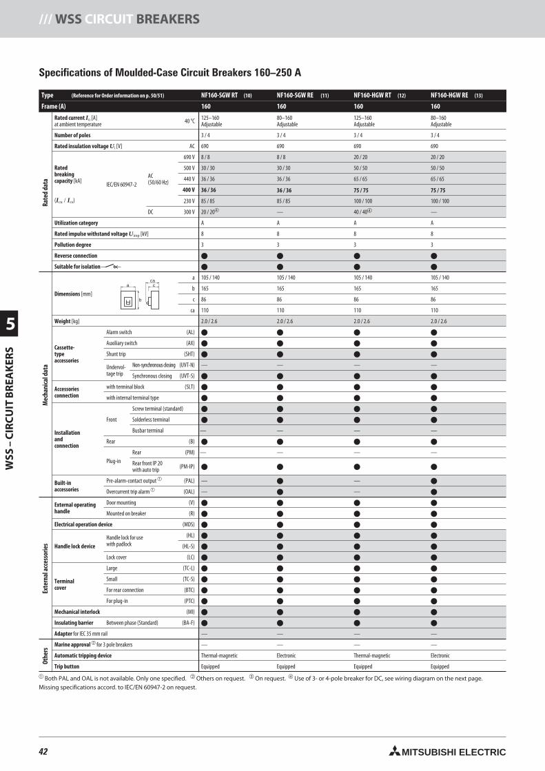
42 MITSUBISHI ELECTRIC
5
WSS
–C
IRC
UIT
BR
EAK
ERS
/// WSS CIRCUIT BREAKERS
Specifications of Moulded-Case Circuit Breakers 160–250 A
a
b
cca
Type (Reference for Order information on p. 50/51) NF160-SGW RT (10) NF160-SGW RE (11) NF160-HGW RT (12) NF160-HGW RE (13)
Frame (A) 160 160 160 160
Rated current In [A]at ambient temperature 40 °C 125–160
Adjustable80–160Adjustable
125–160Adjustable
80–160Adjustable
Number of poles 3 / 4 3 / 4 3 / 4 3 / 4
Rated insulation voltage Ui [V] AC 690 690 690 690
Ratedbreakingcapacity [kA]
(Icu / Ics)
IEC/EN 60947-2AC(50/60 Hz)
690 V 8 / 8 8 / 8 20 / 20 20 / 20
500 V 30 / 30 30 / 30 50 / 50 50 / 50
440 V 36 / 36 36 / 36 65 / 65 65 / 65
400 V 36 / 36 36 / 36 75 / 75 75 / 75
230 V 85 / 85 85 / 85 100 / 100 100 / 100
DC 300 V 20 / 20 — 40 / 40 —
Utilization category A A A A
Rated impulse withstand voltage Uimp [kV] 8 8 8 8
Pollution degree 3 3 3 3
Reverse connection
Suitable for isolation
Dimensions [mm]
a 105 / 140 105 / 140 105 / 140 105 / 140
b 165 165 165 165
c 86 86 86 86
ca 110 110 110 110
Weight [kg] 2.0 / 2.6 2.0 / 2.6 2.0 / 2.6 2.0 / 2.6
Cassette-typeaccessories
Alarm switch (AL)
Auxiliary switch (AX)
Shunt trip (SHT)
Undervol-tage trip
Non-synchronousclosing (UVT-N) — — — —
Synchronous closing (UVT-S)
Accessoriesconnection
with terminal block (SLT)
with internal terminal type
Installationandconnection
Front
Screw terminal (standard)
Solderless terminal
Busbar terminal — — — —
Rear (B)
Plug-inRear (PM) — — — —
Rear front IP 20with auto trip (PM-IP)
Built-inaccessories
Pre-alarm-contact output (PAL) — —
Overcurrent trip alarm (OAL) — —
External operatinghandle
Door mounting (V)
Mounted on breaker (R)
Electrical operation device (MDS)
Handle lock deviceHandle lock for usewith padlock
(HL)
(HL-S)
Lock cover (LC)
Terminalcover
Large (TC-L)
Small (TC-S)
For rear connection (BTC)
For plug-in (PTC)
Mechanical interlock (MI)
Insulating barrier Between phase (Standard) (BA-F)
Adapter for IEC 35 mm rail — — — — for 3 pole breakers — — — —
Automatic tripping device Thermal-magnetic Electronic Thermal-magnetic Electronic
Trip button Equipped Equipped Equipped Equipped
Both PAL and OAL is not available. Only one specified. Others on request. On request. Use of 3- or 4-pole breaker for DC, see wiring diagram on the next page.Missing specifications accord. to IEC/EN 60947-2 on request.
Rate
dda
taM
echa
nica
ldat
aEx
tern
alac
cess
orie
sOt
hers
42neue Seiten_GB.prnLVS-Family - Technical SectionFreitag, 30. Januar 2009 14:16:31
Farbprofil: DeaktiviertKomposit Standardbildschirm

43MITSUBISHI ELECTRIC
WSS
–C
IRC
UIT
BR
EAK
ERS
5
WSS CIRCUIT BREAKERS ///
NF250-SGW RT (14) NF250-SGW RE (15) NF250-HGW RT (16) NF250-HGW RE (17) NF250-RGW RT (18) NF250-UGW RT (19)
250 250 250 250 250 250
125–160, 160–250Adjustable
125–250Adjustable
125–160, 160–250Adjustable
125–250Adjustable
125–160, 160–225Adjustable
125–160, 160–225Adjustable
3 / 4 3 / 4 3 / 4 3 / 4 3 3 / 4
690 690 690 690 690 690
8 / 8 8 / 8 20 / 20 20 / 20 25 / 25 30 / 30
30 / 30 30 / 30 50 / 50 50 / 50 125 / 125 200 / 200
36 / 36 36 / 36 65 / 65 65 / 65 125 / 125 200 / 200
36 / 36 36 / 36 75 / 75 75 / 75 125 / 125 200 / 200
85 / 85 85 / 85 100 / 100 100 / 100 125 / 125 200 / 200
20 / 20 — 40 / 40 — — —
A A A A A A
8 8 8 8 8 8
3 3 3 3 3 3
105 / 140 105 / 140 105 / 140 105 / 140 105 105 / 140
165 165 165 165 240 240
86 86 86 86 86 86
110 110 110 110 110 110
2.0 / 2.6 2.0 / 2.6 2.0 / 2.6 2.0 / 2.6 3.1 3.1 / 3.9
— — — — — —
— — — — — —
— — — — — — /
—
— — — —
— — — —
/ —
— — — — — —
LR, GL, BV, DNV, AB LR, GL, BV, DNV, AB LR, GL, BV, DNV, AB LR, GL, BV, DNV, AB LR, GL, BV, DNV, AB LR, GL, BV, DNV, AB
Thermal-magnetic Electronic Thermal-magnetic Electronic Thermal-magnetic Thermal-magnetic
Equipped Equipped Equipped Equipped Equipped Equipped
N
Line Load LoadLine
3-pole 4-poleUse of 3- and 4-polebreakers for DC
43neue Seiten_GB.prnLVS-Family - Technical SectionFreitag, 30. Januar 2009 14:16:39
Farbprofil: DeaktiviertKomposit Standardbildschirm
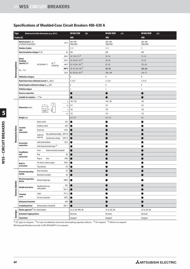
44 MITSUBISHI ELECTRIC
5
WSS
–C
IRC
UIT
BR
EAK
ERS
/// WSS CIRCUIT BREAKERS
Type (Reference for Order information on p. 50/51) NF400-SEW (20) NF400-HEW (21) NF400-REW (22)
Frame (A) 400 400 400
Rated current In [A]at ambient temperature 40 °C 200–400
Adjustable200–400Adjustable
200–400Adjustable
Number of poles 3 / 4 3 / 4 3
Rated insulation voltage Ui [V] AC 690 690 690
Ratedbreakingcapacity [kA]
(Icu / Ics)
IEC/EN 60947-2 AC
(50/60 Hz)
690 V 10 / 10 (5 / 5) 10 / 10 15 / 10
500 V 30 / 30 (25 / 25) 50 / 50 70 / 35
440 V 42 / 42 (36 / 36) 65 / 65 125 / 63
400 V 70 / 70 125 / 63
230 V 85 / 85 (65 / 65) 100 / 100 150 / 75
Utilization category B B B
Rated short-time withstand current Icw [kA/s] 5 / 0.25 5 / 0.25 5 / 0.25
Rated impulse withstand voltage Uimp [kV] 8 8 8
Pollution degree 3 3 3
Reverse connection
Suitable for isolation
Dimensions [mm]
a 140 / 185 140 / 185 140
b 257 257 257
c 103 103 103
ca 155 155 155
Weight [kg] 6.0 / 7.8 6.0 / 7.8 6.0
Cassette-typeaccessories
Alarm switch (AL)
Auxiliary switch (AX)
Shunt trip (SHT)
Undervol-tage trip
Non-synchronousclosing (UVT-N)
Synchronous closing (UVT-S)
Accessoriesconnection
with terminal block (SLT)
with internal terminal type
Installationandconnection
Front Busbar terminal (standard)
Rear (B)
Plug-in Rear (PM)
Built-inaccessories
Pre-alarm-contact output (PAL)
Trip indicator (TI)
External operatinghandle
Door mounting (V)
Mounted on breaker (R)
Electrical operationdevice Spring-charge type (MDS)
Handle lock device Handle lock for usewith padlock
(HL)
(HL-S)
Terminalcover
Large (TC-L)
For rear connection (BTC)
Mechanical interlock (MI)
Insulating barrier Between phase (Standard) (BA-F)
Marine approval for 3 pole breakers LR, GL, BV, DNV, AB LR, GL, BV, AB LR, GL, BV, AB
Automatic tripping device Electronic Electronic Electronic
Trip button Equipped Equipped Equipped
DC type on request. In case of solderless terminal, interrupting capacity reduces. On request. Others on request.Missing specifications accord. to IEC/EN 60947-2 on request.
Specifications of Moulded-Case Circuit Breakers 400–630 A
a
b
cca
Bem
essu
ngsd
aten
Mec
hani
sche
Date
nEx
tern
esZu
behö
rSo
nstig
es
44neue Seiten_GB.prnLVS-Family - Technical SectionFreitag, 30. Januar 2009 14:16:51
Farbprofil: DeaktiviertKomposit Standardbildschirm
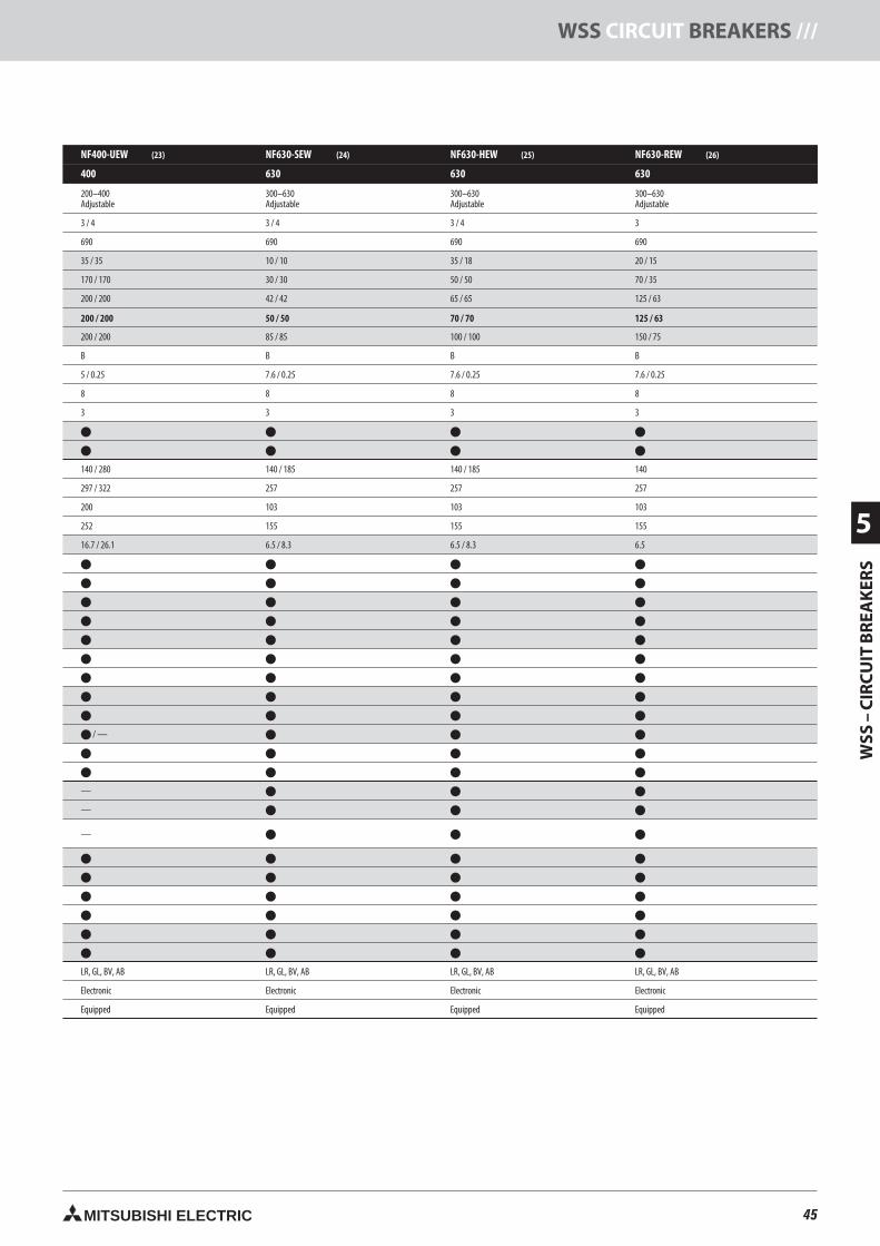
45MITSUBISHI ELECTRIC
WSS
–C
IRC
UIT
BR
EAK
ERS
5
WSS CIRCUIT BREAKERS ///
NF400-UEW (23) NF630-SEW (24) NF630-HEW (25) NF630-REW (26)
400 630 630
200–400Adjustable
300–630Adjustable
300–630Adjustable
300–630Adjustable
3 / 4 3 / 4 3 / 4 3
690 690 690 690
35 / 35 10 / 10 35 / 18 20 / 15
170 / 170 30 / 30 50 / 50 70 / 35
200 / 200 42 / 42 65 / 65 125 / 63
200 / 200 50 / 50 70 / 70 125 / 63
200 / 200 85 / 85 100 / 100 150 / 75
B B B B
5 / 0.25 7.6 / 0.25 7.6 / 0.25 7.6 / 0.25
8 8 8 8
3 3 3 3
140 / 280 140 / 185 140 / 185 140
297 / 322 257 257 257
200 103 103 103
252 155 155 155
16.7 / 26.1 6.5 / 8.3 6.5 / 8.3 6.5
/ —
—
—
—
LR, GL, BV, AB LR, GL, BV, AB LR, GL, BV, AB LR, GL, BV, AB
Electronic Electronic Electronic Electronic
Equipped Equipped Equipped Equipped
45neue Seiten_GB.prnLVS-Family - Technical SectionFreitag, 30. Januar 2009 14:16:56
Farbprofil: DeaktiviertKomposit Standardbildschirm
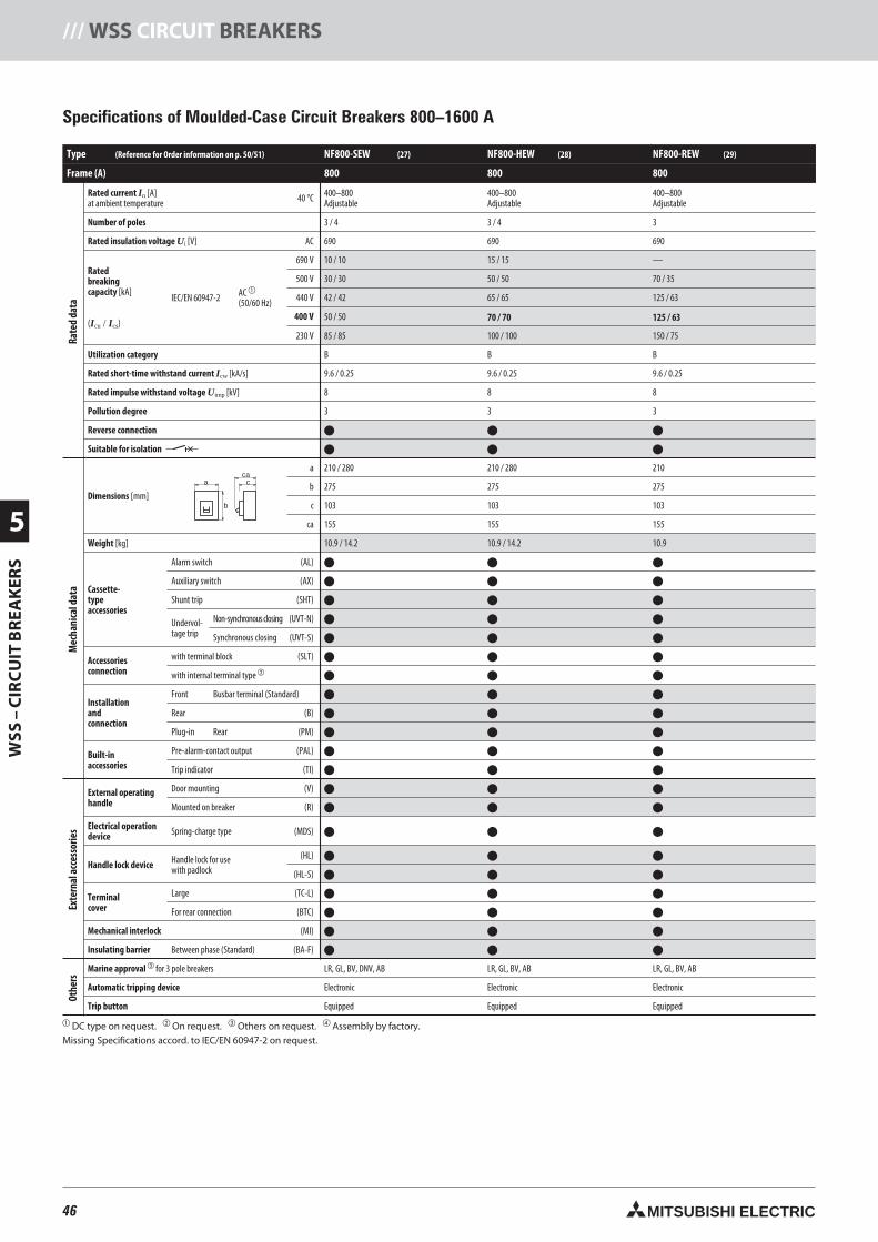
46 MITSUBISHI ELECTRIC
5
WSS
–C
IRC
UIT
BR
EAK
ERS
/// WSS CIRCUIT BREAKERS
Type (Reference for Order information on p. 50/51) NF800-SEW (27) NF800-HEW (28) NF800-REW (29)
Frame (A) 800 800
Rated current In [A]at ambient temperature 40 °C 400–800
Adjustable400–800Adjustable
400–800Adjustable
Number of poles 3 / 4 3 / 4 3
Rated insulation voltage Ui [V] AC 690 690 690
Ratedbreakingcapacity [kA]
(Icu / Ics)
IEC/EN 60947-2 AC
(50/60 Hz)
690 V 10 / 10 15 / 15 —
500 V 30 / 30 50 / 50 70 / 35
440 V 42 / 42 65 / 65 125 / 63
400 V 70 / 70 125 / 63
230 V 85 / 85 100 / 100 150 / 75
Utilization category B B B
Rated short-time withstand current Icw [kA/s] 9.6 / 0.25 9.6 / 0.25 9.6 / 0.25
Rated impulse withstand voltage Uimp [kV] 8 8 8
Pollution degree 3 3 3
Reverse connection
Suitable for isolation
Dimensions [mm]
a 210 / 280 210 / 280 210
b 275 275 275
c 103 103 103
ca 155 155 155
Weight [kg] 10.9 / 14.2 10.9 / 14.2 10.9
Cassette-typeaccessories
Alarm switch (AL)
Auxiliary switch (AX)
Shunt trip (SHT)
Undervol-tage trip
Non-synchronousclosing (UVT-N)
Synchronous closing (UVT-S)
Accessoriesconnection
with terminal block (SLT)
with internal terminal type
Installationandconnection
Front Busbar terminal (Standard)
Rear (B)
Plug-in Rear (PM)
Built-inaccessories
Pre-alarm-contact output (PAL)
Trip indicator (TI)
External operatinghandle
Door mounting (V)
Mounted on breaker (R)
Electrical operationdevice Spring-charge type (MDS)
Handle lock device Handle lock for usewith padlock
(HL)
(HL-S)
Terminalcover
Large (TC-L)
For rear connection (BTC)
Mechanical interlock (MI)
Insulating barrier Between phase (Standard) (BA-F)
Marine approval for 3 pole breakers LR, GL, BV, DNV, AB LR, GL, BV, AB LR, GL, BV, AB
Automatic tripping device Electronic Electronic Electronic
Trip button Equipped Equipped Equipped
DC type on request. On request. Others on request. Assembly by factory.Missing Specifications accord. to IEC/EN 60947-2 on request.
Specifications of Moulded-Case Circuit Breakers 800–1600 A
a
b
cca
Rate
dda
taM
echa
nica
ldat
aEx
tern
alac
cess
orie
sOt
hers
46neue Seiten_GB.prnLVS-Family - Technical SectionFreitag, 30. Januar 2009 14:17:06
Farbprofil: DeaktiviertKomposit Standardbildschirm
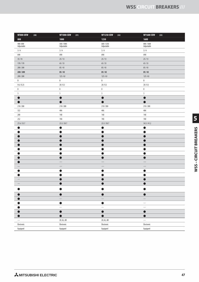
47MITSUBISHI ELECTRIC
WSS
–C
IRC
UIT
BR
EAK
ERS
5
WSS CIRCUIT BREAKERS ///
NF800-UEW (30) NF1000-SEW (31) NF1250-SEW (32) NF1600-SEW (33)
800 1000 1250 1600
400–800Adjustable
500–1000Adjustable
600–1250Adjustable
800–1600Adjustable
3 / 4 3 / 4 3 / 4 3 / 4
690 690 690 690
35 / 35 25 / 13 25 / 13 25 / 13
170 / 170 65 / 33 65 / 33 65 / 33
200 / 200 85 / 43 85 / 43 85 / 43
200 / 200 85 / 43 85 / 43 85 / 43
200 / 200 125 / 63 125 / 63 125 / 63
B B B B
9.6 / 0.25 20 / 0.3 20 / 0.3 20 / 0.3
8 8 8 8
3 3 3 3
210 / 280 210 / 280 210 / 280 210 / 280
322 406 406 406
200 140 140 140
252 190 190 190
27.6 / 33.7 23.5 / 30.7 23.5 / 30.7 34.5 / 41.2
— — —
— — — —
—
—
— — —
—
— — —
— LR, GL, AB LR, GL, AB —
Electronic Electronic Electronic Electronic
Equipped Equipped Equipped Equipped
47neue Seiten_GB.prnLVS-Family - Technical SectionFreitag, 30. Januar 2009 14:17:12
Farbprofil: DeaktiviertKomposit Standardbildschirm
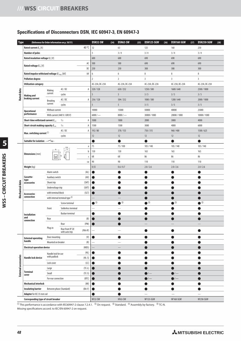
48 MITSUBISHI ELECTRIC
5
WSS
–C
IRC
UIT
BR
EAK
ERS
/// WSS CIRCUIT BREAKERS
Specifications of Disconnectors DSN, IEC 60947-3, EN 60947-3
Type (Reference for Order information on p. 50/51) DSN32-SW (34) DSN63-SW (35) DSN125-SGW (36) DSN160-SGW (37) DSN250-SGW (38)
Rated current In [A] 40 °C 32 63 125 160 250
Number of poles 3 3 / 4 3 / 4 3 / 4 3 / 4
Rated insulation voltage Ui [V] 600 600 690 690 690
Rated voltage Ue [V]AC 500 500 690 690 690
DC 250 250 300 300 300
Rated impulse withstand voltage Uimp [kV] kV 6 6 8 8 8
Pollution degree 2 2 3 3 3
Utilization category AC-23A, DC-23A AC-23A, DC-23A AC-23A, DC-23A AC-23A, DC-23A AC-23A, DC-23A
Making andbraking current
Makingcurrent
AC / DC A 320 / 128 630 / 252 1250 / 500 1600 / 640 2500 / 1000
cycles 5 5 3 / 5 3 / 5 3 / 5
Breakingcurrent
AC / DC A 256 / 128 504 / 252 1000 / 500 1280 / 640 2000 / 1000
cycles 5 5 3 / 5 3 / 5 3 / 5
Operationalperformance
Without current 10000 15000 50000 40000 25000
With current (440 V / 690 V) 6000 / — 8000 / — 30000 / 1000 20000 / 1000 10000 / 1000
Short-time withstand current Icw 1 s A 1000 1000 2000 3000 4000
Short-circuit making capacity Icm 1 s A 1500 1500 3000 4000 6000
Max. switching current AC / DC A 192 / 80 378 / 155 750 / 315 960 / 400 1500 / 625
cycles 12 12 12 12 12
Suitable for isolation
Dimensions [mm]
a 75 75 / 100 105 / 140 105 / 140 105 / 140
b 130 130 165 165 165
c 68 68 86 86 86
ca 90 90 110 110 110
Weight [kg] 0.55 0.6 / 0.7 2.0 / 2.6 2.0 / 2.6 2.0 / 2.6
Cassette-typeaccessories
Alarm switch (AL)
Auxiliary switch (AX)
Shunt trip (SHT)
Undervoltage trip (UVT)
Accessoriesconnection
with terminal block (SLT)
with internal terminal type — —
Installationandconnection
Front
Screw terminal
Solderless terminal — —
Busbar terminal
Rear (B)
Plug-in
Rear (PM) — — —
Rear front IP 20with auto trip (PM-IP) — —
External operatinghandle
Door mounting (V)
Mounted on breaker (R) — —
Electrical operation device (MDS) — —
Handle lock device
Handle lock for usewith padlock
(HL)
(HL-S)
Lock cover (LC)
Terminalcover
Large (TC-L)
Small (TC-S) / — / —
For rear connection (BTC) / — / —
Mechanical interlock (MI)
Insulating barrier Between phase (Standard) (BA-F)
Adapter for IEC 35 mm rail — — —
Corresponding type of circuit breaker
This performance is accordance with IEC60947-2 clause 7.2.4.1. On request. Standard. Assembly by factory. TC-N.Missing specifications accord. to IEC/EN 60947-2 on request.
a
b
cca
Rate
dda
taM
echa
nica
ldat
aEx
tern
alac
cess
orie
s
48neue Seiten_GB.prnLVS-Family - Technical SectionFreitag, 30. Januar 2009 14:17:23
Farbprofil: DeaktiviertKomposit Standardbildschirm
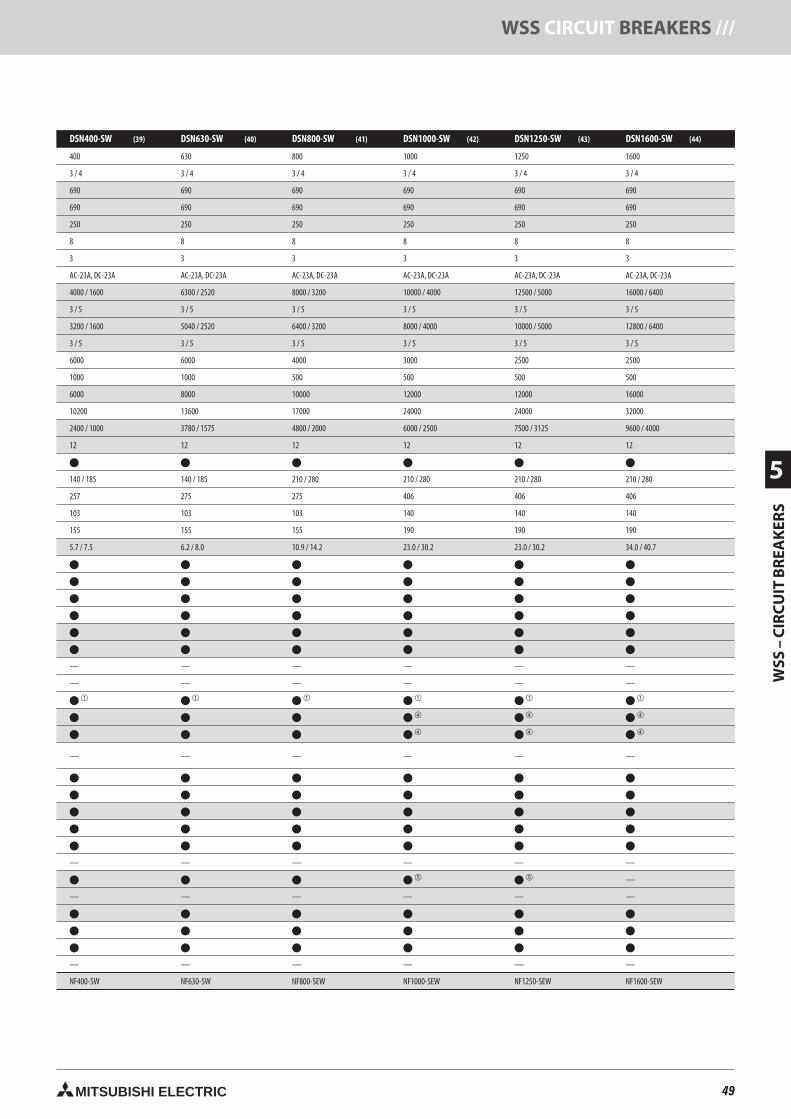
49MITSUBISHI ELECTRIC
WSS
–C
IRC
UIT
BR
EAK
ERS
5
WSS CIRCUIT BREAKERS ///
DSN400-SW (39) DSN630-SW (40) DSN800-SW (41) DSN1000-SW (42) DSN1250-SW (43) DSN1600-SW (44)
400 630 800 1000 1250 1600
3 / 4 3 / 4 3 / 4 3 / 4 3 / 4 3 / 4
690 690 690 690 690 690
690 690 690 690 690 690
250 250 250 250 250 250
8 8 8 8 8 8
3 3 3 3 3 3
AC-23A, DC-23A AC-23A, DC-23A AC-23A, DC-23A AC-23A, DC-23A AC-23A, DC-23A AC-23A, DC-23A
4000 / 1600 6300 / 2520 8000 / 3200 10000 / 4000 12500 / 5000 16000 / 6400
3 / 5 3 / 5 3 / 5 3 / 5 3 / 5 3 / 5
3200 / 1600 5040 / 2520 6400 / 3200 8000 / 4000 10000 / 5000 12800 / 6400
3 / 5 3 / 5 3 / 5 3 / 5 3 / 5 3 / 5
6000 6000 4000 3000 2500 2500
1000 1000 500 500 500 500
6000 8000 10000 12000 12000 16000
10200 13600 17000 24000 24000 32000
2400 / 1000 3780 / 1575 4800 / 2000 6000 / 2500 7500 / 3125 9600 / 4000
12 12 12 12 12 12
140 / 185 140 / 185 210 / 280 210 / 280 210 / 280 210 / 280
257 275 275 406 406 406
103 103 103 140 140 140
155 155 155 190 190 190
5.7 / 7.5 6.2 / 8.0 10.9 / 14.2 23.0 / 30.2 23.0 / 30.2 34.0 / 40.7
— — — — — —
— — — — — —
— — — — — —
— — — — — —
—
— — — — — —
— — — — — —
49neue Seiten_GB.prnLVS-Family - Technical SectionFreitag, 30. Januar 2009 14:17:27
Farbprofil: DeaktiviertKomposit Standardbildschirm
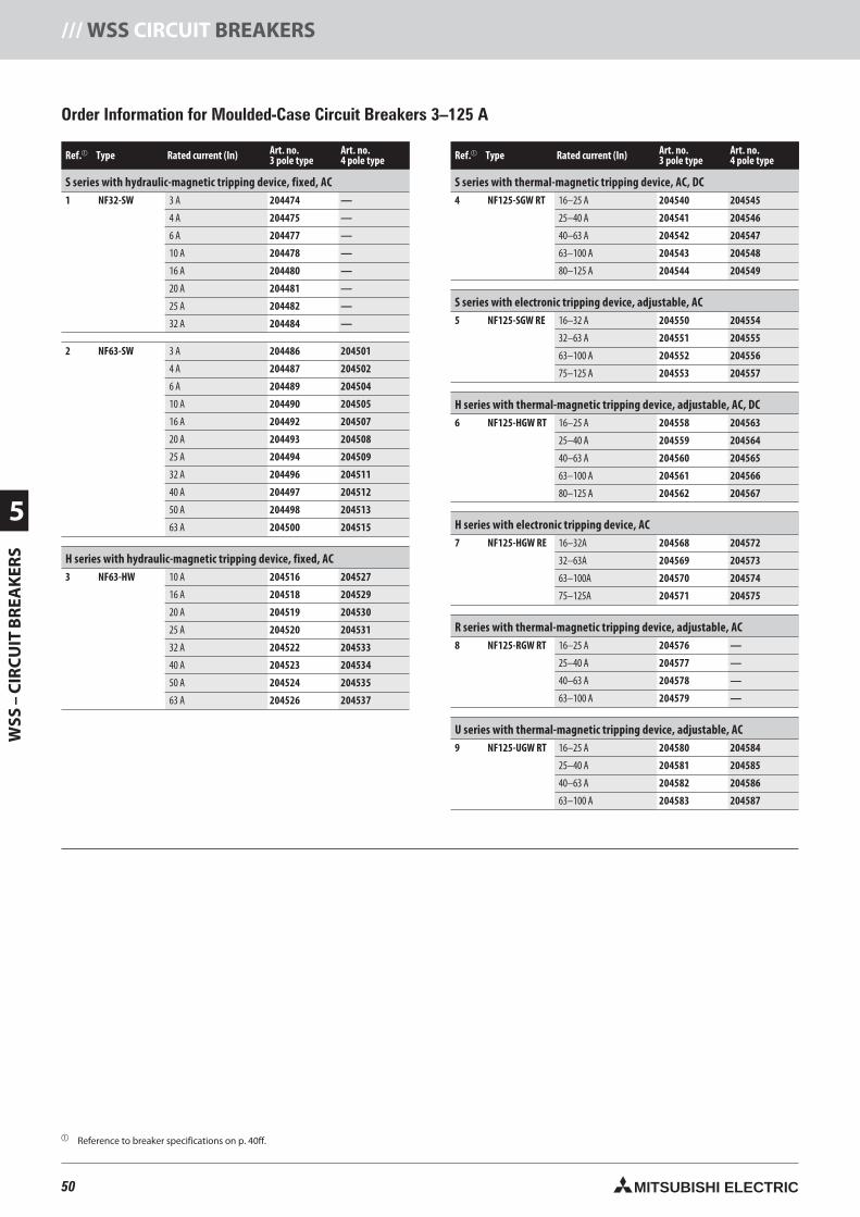
50 MITSUBISHI ELECTRIC
5
WSS
–C
IRC
UIT
BR
EAK
ERS
/// WSS CIRCUIT BREAKERS
Order Information for Moulded-Case Circuit Breakers 3–125 A
Ref. Type Rated current (In) Art. no.3 pole type
Art. no.4 pole type
S series with hydraulic-magnetic tripping device, fixed, AC1 NF32-SW 3 A 204474 —
4 A 204475 —
6 A 204477 —
10 A 204478 —
16 A 204480 —
20 A 204481 —
25 A 204482 —
32 A 204484 —
2 NF63-SW 3 A 204486 204501
4 A 204487 204502
6 A 204489 204504
10 A 204490 204505
16 A 204492 204507
20 A 204493 204508
25 A 204494 204509
32 A 204496 204511
40 A 204497 204512
50 A 204498 204513
63 A 204500 204515
H series with hydraulic-magnetic tripping device, fixed, AC3 NF63-HW 10 A 204516 204527
16 A 204518 204529
20 A 204519 204530
25 A 204520 204531
32 A 204522 204533
40 A 204523 204534
50 A 204524 204535
63 A 204526 204537
Ref. Type Rated current (In) Art. no.3 pole type
Art. no.4 pole type
S series with thermal-magnetic tripping device, AC, DC4 NF125-SGW RT 16–25 A 204540 204545
25–40 A 204541 204546
40–63 A 204542 204547
63–100 A 204543 204548
80–125 A 204544 204549
S series with electronic tripping device, adjustable, AC5 NF125-SGW RE 16–32 A 204550 204554
32–63 A 204551 204555
63–100 A 204552 204556
75–125 A 204553 204557
H series with thermal-magnetic tripping device, adjustable, AC, DC6 NF125-HGW RT 16–25 A 204558 204563
25–40 A 204559 204564
40–63 A 204560 204565
63–100 A 204561 204566
80–125 A 204562 204567
H series with electronic tripping device, AC7 NF125-HGW RE 16–32A 204568 204572
32–63A 204569 204573
63–100A 204570 204574
75–125A 204571 204575
R series with thermal-magnetic tripping device, adjustable, AC8 NF125-RGW RT 16–25 A 204576 —
25–40 A 204577 —
40–63 A 204578 —
63–100 A 204579 —
U series with thermal-magnetic tripping device, adjustable, AC9 NF125-UGW RT 16–25 A 204580 204584
25–40 A 204581 204585
40–63 A 204582 204586
63–100 A 204583 204587
Reference to breaker specifications on p. 40ff.
50neue Seiten_GB.prnLVS-Family - Technical SectionFreitag, 30. Januar 2009 14:17:32
Farbprofil: DeaktiviertKomposit Standardbildschirm
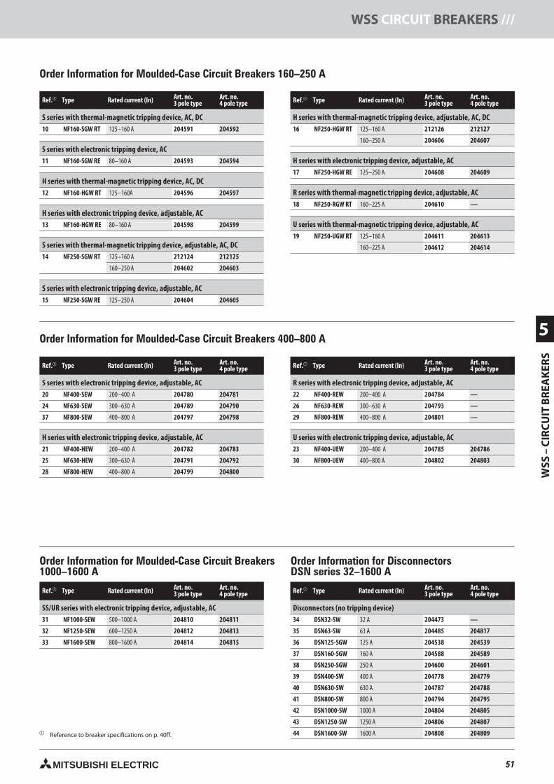
51MITSUBISHI ELECTRIC
WSS
–C
IRC
UIT
BR
EAK
ERS
5
WSS CIRCUIT BREAKERS ///
Order Information for DisconnectorsDSN series 32–1600 A
Order Information for Moulded-Case Circuit Breakers 400–800 A
Reference to breaker specifications on p. 40ff.
Ref. Type Rated current (In) Art. no.3 pole type
Art. no.4 pole type
S series with thermal-magnetic tripping device, AC, DC10 NF160-SGW RT 125–160 A 204591 204592
S series with electronic tripping device, AC11 NF160-SGW RE 80–160 A 204593 204594
H series with thermal-magnetic tripping device, AC, DC12 NF160-HGW RT 125–160A 204596 204597
H series with electronic tripping device, adjustable, AC13 NF160-HGW RE 80–160 A 204598 204599
S series with thermal-magnetic tripping device, adjustable, AC, DC14 NF250-SGW RT 125–160 A 212124 212125
160–250 A 204602 204603
S series with electronic tripping device, adjustable, AC15 NF250-SGW RE 125–250 A 204604 204605
Ref. Type Rated current (In) Art. no.3 pole type
Art. no.4 pole type
H series with thermal-magnetic tripping device, adjustable, AC, DC16 NF250-HGW RT 125–160 A 212126 212127
160–250 A 204606 204607
H series with electronic tripping device, adjustable, AC17 NF250-HGW RE 125–250 A 204608 204609
R series with thermal-magnetic tripping device, adjustable, AC18 NF250-RGW RT 160–225 A 204610 —
U series with thermal-magnetic tripping device, adjustable, AC19 NF250-UGW RT 125–160 A 204611 204613
160–225 A 204612 204614
Order Information for Moulded-Case Circuit Breakers1000–1600 A
Order Information for Moulded-Case Circuit Breakers 160–250 A
Ref. Type Rated current (In) Art. no.3 pole type
Art. no.4 pole type
S series with electronic tripping device, adjustable, AC20 NF400-SEW 200–400 A 204780 204781
24 NF630-SEW 300–630 A 204789 204790
37 NF800-SEW 400–800 A 204797 204798
H series with electronic tripping device, adjustable, AC21 NF400-HEW 200–400 A 204782 204783
25 NF630-HEW 300–630 A 204791 204792
28 NF800-HEW 400–800 A 204799 204800
Ref. Type Rated current (In) Art. no.3 pole type
Art. no.4 pole type
R series with electronic tripping device, adjustable, AC22 NF400-REW 200–400 A 204784 —
26 NF630-REW 300–630 A 204793 —
29 NF800-REW 400–800 A 204801 —
U series with electronic tripping device, adjustable, AC23 NF400-UEW 200–400 A 204785 204786
30 NF800-UEW 400–800 A 204802 204803
Ref. Type Rated current (In) Art. no.3 pole type
Art. no.4 pole type
SS/UR series with electronic tripping device, adjustable, AC31 NF1000-SEW 500–1000 A 204810 204811
32 NF1250-SEW 600–1250 A 204812 204813
33 NF1600-SEW 800–1600 A 204814 204815
Ref. Type Rated current (In) Art. no.3 pole type
Art. no.4 pole type
Disconnectors (no tripping device)34 DSN32-SW 32 A 204473 —
35 DSN63-SW 63 A 204485 204817
36 DSN125-SGW 125 A 204538 204539
37 DSN160-SGW 160 A 204588 204589
38 DSN250-SGW 250 A 204600 204601
39 DSN400-SW 400 A 204778 204779
40 DSN630-SW 630 A 204787 204788
41 DSN800-SW 800 A 204794 204795
42 DSN1000-SW 1000 A 204804 204805
43 DSN1250-SW 1250 A 204806 204807
44 DSN1600-SW 1600 A 204808 204809
51neue Seiten_GB.prnLVS-Family - Technical SectionFreitag, 30. Januar 2009 14:17:37
Farbprofil: DeaktiviertKomposit Standardbildschirm
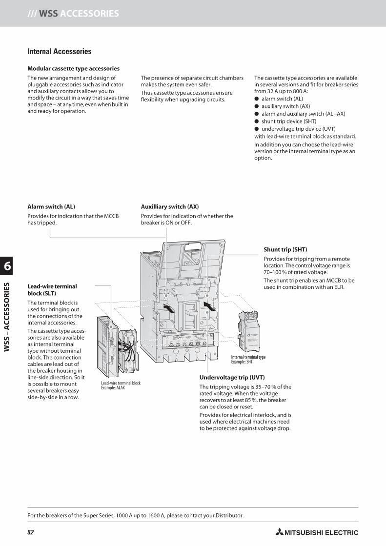
52 MITSUBISHI ELECTRIC
6
WSS
–A
CC
ESSO
RIE
S/// WSS ACCESSORIES
63 100 10012 22.5
10 .06.07 .10
.3 4
6
8 10
12
14
.1 .2
87
65480 3.53
60 80
PAL70%50/60Hz
T
TsTL
IiIs
IrIp
Ii(X100A)
Ir(A) TL(S) IS(xIr) TS(S) Ip(xIr)
OVERMODEL
RE100 In 100A
AC100-240V50/60Hz
Install and uninstall the
accessory in tripped position,
not in ON or OFF position
SHTA240-2GSWRS
ALAX-2GSWLS
MITSUBISHIELECTRIC
AL
95 c14 a
96 b12 b
98 a11 c
AX
AL
AR
MS
WIT
CH
AC
AC
DC
DC
12
5V
25
0V
12
5V
25
0V
5A
3A
0.4
A0
.2A
98
AL
a9
6A
Lb
98
AL
c
AU
XIL
IAR
YS
WIT
CH
AC
AC
DC
DC
12
5V
25
0V
12
5V
25
0V
5A
3A
0.4
A0
.2A
11
AX
c1
2A
Xb
14
AX
a
Shunt trip (SHT)
Provides for tripping from a remotelocation. The control voltage range is70–100 % of rated voltage.
The shunt trip enables an MCCB to beused in combination with an ELR.Lead-wire terminal
block (SLT)
The terminal block isused for bringing outthe connections of theinternal accessories.
The cassette type acces-sories are also availableas internal terminaltype without terminalblock. The connectioncables are lead out ofthe breaker housing inline-side direction. So itis possible to mountseveral breakers easyside-by-side in a row.
Internal Accessories
Modular cassette type accessories
The new arrangement and design ofpluggable accessories such as indicatorand auxiliary contacts allows you tomodify the circuit in a way that saves timeand space – at any time, even when built inand ready for operation.
The presence of separate circuit chambersmakes the system even safer.
Thus cassette type accessories ensureflexibility when upgrading circuits.
The cassette type accessories are availablein several versions and fit for breaker seriesfrom 32 A up to 800 A: alarm switch (AL) auxiliary switch (AX) alarm and auxiliary switch (AL+AX) shunt trip device (SHT) undervoltage trip device (UVT)with lead-wire terminal block as standard.
In addition you can choose the lead-wireversion or the internal terminal type as anoption.
Alarm switch (AL)
Provides for indication that the MCCBhas tripped.
Auxilliary switch (AX)
Provides for indication of whether thebreaker is ON or OFF.
For the breakers of the Super Series, 1000 A up to 1600 A, please contact your Distributor.
Lead-wire terminal blockExample: ALAX
Internal terminal typeExample: SHT
Undervoltage trip (UVT)
The tripping voltage is 35–70 % of therated voltage. When the voltagerecovers to at least 85 %, the breakercan be closed or reset.
Provides for electrical interlock, and isused where electrical machines needto be protected against voltage drop.
52neue Seiten_GB.prnLVS-Family - Technical SectionFreitag, 30. Januar 2009 14:17:49
Farbprofil: DeaktiviertKomposit Standardbildschirm
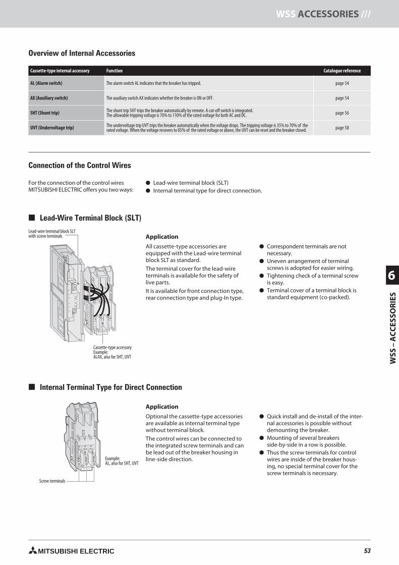
53MITSUBISHI ELECTRIC
WSS
–A
CC
ESSO
RIE
S
6
WSS ACCESSORIES ///
ALAX-2GSWLS
MITSUBISHIELECTRIC
AL
95 c14 a
96 b12 b
98 a11 c
AX
ALA
RM
SW
ITC
HA
CA
CD
CD
C
12
5V
25
0V
12
5V
25
0V
5A
3A
0.4
A0
.2A
98
ALa
96
ALb
98
ALc
AU
XIL
IAR
YS
WIT
CH
AC
AC
DC
DC
12
5V
25
0V
12
5V
25
0V
5A
3A
0.4
A0
.2A
11
AX
c12
AX
b14
AX
a
96ALb
98ALa
AL-2GSWN
MITSUBISHIELECTRIC
Lead-Wire Terminal Block (SLT)
Application
All cassette-type accessories areequipped with the Lead-wire terminalblock SLT as standard.
The terminal cover for the lead-wireterminals is available for the safety oflive parts.
It is available for front connection type,rear connection type and plug-In type.
Correspondent terminals are notnecessary.
Uneven arrangement of terminalscrews is adopted for easier wiring.
Tightening check of a terminal screwis easy.
Terminal cover of a terminal block isstandard equipment (co-packed).
Overview of Internal Accessories
Cassette-type internal accessory Function Catalogue reference
AL (Alarm switch) The alarm switch AL indicates that the breaker has tripped. page 54
AX (Auxiliary switch) The auxiliary switch AX indicates whether the breaker is ON or OFF. page 54
SHT (Shunt trip) The shunt trip SHT trips the breaker automatically by remote. A cut-off switch is integrated.The allowable tripping voltage is 70% to 110% of the rated voltage for both AC and DC. page 56
UVT (Undervoltage trip) The undervoltage trip UVT trips the breaker automatically when the voltage drops. The tripping voltage is 35% to 70% of therated voltage. When the voltage recovers to 85% of the rated voltage or above, the UVT can be reset and the breaker closed. page 58
Cassette-type accessoryExample:ALAX, also for SHT, UVT
Internal Terminal Type for Direct Connection
Example:AL, also for SHT, UVT
Application
Optional the cassette-type accessoriesare available as internal terminal typewithout terminal block.
The control wires can be connected tothe integrated screw terminals and canbe lead out of the breaker housing inline-side direction.
Quick install and de-install of the inter-nal accessories is possible withoutdemounting the breaker.
Mounting of several breakersside-by-side in a row is possible.
Thus the screw terminals for controlwires are inside of the breaker hous-ing, no special terminal cover for thescrew terminals is necessary.
Lead-wire terminal block SLTwith screw terminals
Screw terminals
Connection of the Control Wires
For the connection of the control wiresMITSUBISHI ELECTRIC offers you two ways:
Lead-wire terminal block (SLT) Internal terminal type for direct connection.
53neue Seiten_GB.prnLVS-Family - Technical SectionFreitag, 30. Januar 2009 14:18:02
Farbprofil: DeaktiviertKomposit Standardbildschirm
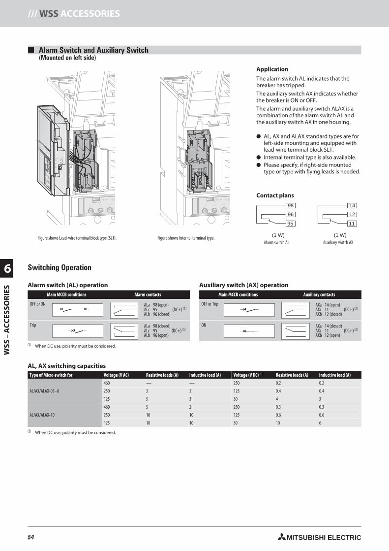
54 MITSUBISHI ELECTRIC
6
WSS
–A
CC
ESSO
RIE
S/// WSS ACCESSORIES
12
11
14
96
95
98
(1 W) (1 W)
C2
S2
C1
S1
SH
T
AC100-240V50/60Hz
Install and uninstall the
accessory in tripped position,
not in ON or OFF position
SHTA240-2GSWRS
50/6Ts
TLIi
Is
IrIp
Ir(A) TL(S) IS(xIr)
MODEL
RE100 In 10
14 a12 b
11 c
AX
AU
XIL
IAR
YS
WIT
CH
AC
AC
DC
DC
12
5V
25
0V
12
5V
25
0V
5A
3A
0.4
A0
.2A
11
AX
c1
2A
Xb
14
AX
a
63 100 10012 22.5
10 .8
765480 3.5
360 80
C2
S2
C1
S1
SH
T
AC100-240V50/60Hz
Install and uninstall the
accessory in tripped position,
not in ON or OFF position
SHTA240-2GSWRS
PAL70%50/60
TsTL
IiIs
IrIp OVERMODEL
RE100 In 10Ts
Ir(A) TL(S) IS(xIr)
63 100 10012 22.5
10 .08
765480 3.5
360 80
Alarm switch (AL) operationMain MCCB conditions Alarm contacts
OFF or ON ALa 98 (open)ALc 95 (DC+)
ALb 96 (closed)
Trip ALa 98 (closed)ALc 95 (DC+)
ALb 96 (open)
When DC use, polarity must be considered.
Auxiliary switch (AX) operationMain MCCB conditions Auxiliary contacts
OFF or Trip AXa 14 (open)AXc 11 (DC+)
AXb 12 (closed)
ON AXa 14 (closed)AXc 11 (DC+)
AXb 12 (open)
Switching Operation
AL, AX switching capacitiesType of Micro-switch for Voltage (V AC) Resistive loads (A) Inductive load (A) Voltage (V DC) Resistive loads (A) Inductive load (A)
AL/AX/ALAX-05–8
460 — — 250 0.2 0.2
250 3 2 125 0.4 0.4
125 5 3 30 4 3
AL/AX/ALAX-10
460 5 2 250 0.3 0.3
250 10 10 125 0.6 0.6
125 10 10 30 10 6
When DC use, polarity must be considered.
Alarm Switch and Auxiliary Switch(Mounted on left side)
Application
The alarm switch AL indicates that thebreaker has tripped.
The auxiliary switch AX indicates whetherthe breaker is ON or OFF.
The alarm and auxiliary switch ALAX is acombination of the alarm switch AL andthe auxiliary switch AX in one housing.
AL, AX and ALAX standard types are forleft-side mounting and equipped withlead-wire terminal block SLT.
Internal terminal type is also available. Please specify, if right-side mounted
type or type with flying leads is needed.
Contact plans
Figure shows Lead-wire terminal block type (SLT). Figure shows Internal terminal type.Alarm switch AL Auxiliary switch AX
54neue Seiten_GB.prnLVS-Family - Technical SectionFreitag, 30. Januar 2009 14:18:25
Farbprofil: DeaktiviertKomposit Standardbildschirm
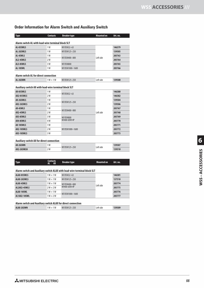
55MITSUBISHI ELECTRIC
WSS
–A
CC
ESSO
RIE
S
6
WSS ACCESSORIES ///
Type Contacts Breaker type Mounted on Art. no.
Alarm switch AL with lead-wire terminal block SLTAL-05SWLS 1 W NF/DSN32–63
Left side
146379
AL-2GSWLS 1 W NF/DSN125–250 139505
AL-4SWLS 1 WNF/DSN400–800
205763
AL2-4SWLS 2 W 205764
AL3-8SWLS 3 W NF/DSN800 205765
AL-10SWL 1 W NF/DSN1000–1600 205766
Alarm switch AL for direct connectionAL-2GSWN 1 W + 1 W NF/DSN125–250 Left side 139508
Auxiliary switch AX with lead-wire terminal block SLTAX-05SWLS 1 W
NF/DSN32–63
Left side
146380
AX2-05SWLS 2 W 146382
AX-2GSWLS 1 WNF/DSN125–250
139504
AX2-2GSWLS 2 W 139506
AX-4SWLS 1 WNF/DSN400–800
205767
AX2-4SWLS 2 W 205768
AX3-8SWLS 3 W NF/DSN800NF400-UEW 4P
205769
AX4-8SWLS 4 W 205770
AX-10SWLS 1 W
NF/DSN1000–1600
205771
AX2-10SWLS 2 W 205772
AX3-10SWLS 3 W 205773
Auxiliary switch AX for direct connectionAX-2GSWN 1 W
NF/DSN125–250 Left side139507
AX2-2GSWLN 2 W 139510
Type ContactsAL AX Breaker type Mounted on Art. no.
Alarm switch and Auxiliary switch ALAX with lead-wire terminal block SLTALAX-05SWLS 1 W + 1 W NF/DSN32–63
Left side
146381
ALAX-2GSWLS 1 W + 1 W NF/DSN125–250 137510
ALAX-4SWLS 1 W + 1 W NF/DSN400–800NF400-UEW 4P
205774
AL2AX2-4SWLS 2 W + 2 W 205775
ALAX-10SWL 1 W + 1 WNF/DSN1000–1600
205776
AL1AX2-10SWL 1 W + 2 W 205777
Alarm switch and Auxiliary switch ALAX for direct connectionALAX-2GSWN 1 W + 1 W NF/DSN125–250 Left side 139509
Order Information for Alarm Switch and Auxiliary Switch
55neue Seiten_GB.prnLVS-Family - Technical SectionFreitag, 30. Januar 2009 14:18:30
Farbprofil: DeaktiviertKomposit Standardbildschirm
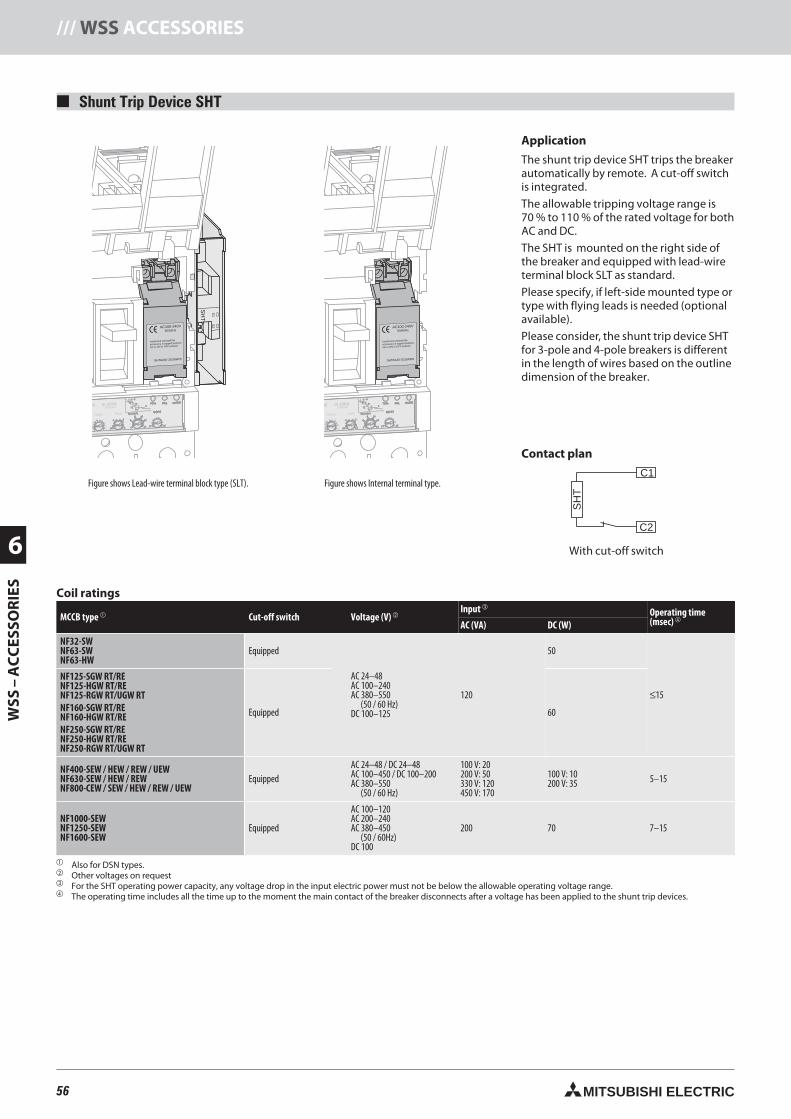
56 MITSUBISHI ELECTRIC
6
WSS
–A
CC
ESSO
RIE
S/// WSS ACCESSORIES
C1
C2
SH
TC
2S
2C
1S
1
SH
T
PAL70%50/60Hz
T
TsTL
IiIs
IrIp
Ii(X100A)IS(xIr) TS(S) Ip(xIr)
25
10 .06.07 .10
.3 4
6
8 10
12
14
.1 .2
87
6543.53
OVER00 In 100A
AC100-240V50/60Hz
Install and uninstall the
accessory in tripped position,
not in ON or OFF position
SHTA240-2GSWRS
PAL70%50/60Hz
T
TsTL
IiIs
IrIp
Ii(X100A)IS(xIr) TS(S) Ip(xIr)
25
10 .06.07 .10
.3 4
6
8 10
12
14
.1 .2
87
6543.53
OVER00 In 100A
AC100-240V50/60Hz
Install and uninstall the
accessory in tripped position,
not in ON or OFF position
SHTA240-2GSWRS
Shunt Trip Device SHT
Application
The shunt trip device SHT trips the breakerautomatically by remote. A cut-off switchis integrated.
The allowable tripping voltage range is70 % to 110 % of the rated voltage for bothAC and DC.
The SHT is mounted on the right side ofthe breaker and equipped with lead-wireterminal block SLT as standard.
Please specify, if left-side mounted type ortype with flying leads is needed (optionalavailable).
Please consider, the shunt trip device SHTfor 3-pole and 4-pole breakers is differentin the length of wires based on the outlinedimension of the breaker.
Coil ratings
MCCB type Cut-off switch Voltage (V) Input
Operating time(msec)
AC (VA) DC (W)
NF32-SWNF63-SWNF63-HW
Equipped
AC 24–48AC 100–240AC 380–550
(50 / 60 Hz)DC 100–125
120
50
≤15
NF125-SGW RT/RENF125-HGW RT/RENF125-RGW RT/UGW RTNF160-SGW RT/RENF160-HGW RT/RENF250-SGW RT/RENF250-HGW RT/RENF250-RGW RT/UGW RT
Equipped 60
NF400-SEW / HEW / REW / UEWNF630-SEW / HEW / REWNF800-CEW / SEW / HEW / REW / UEW
EquippedAC 24–48 / DC 24–48AC 100–450 / DC 100–200AC 380–550
(50 / 60 Hz)
100 V: 20200 V: 50330 V: 120450 V: 170
100 V: 10200 V: 35 5–15
NF1000-SEWNF1250-SEWNF1600-SEW
Equipped
AC 100–120AC 200–240AC 380–450
(50 / 60Hz)DC 100
200 70 7–15
Also for DSN types. Other voltages on request For the SHT operating power capacity, any voltage drop in the input electric power must not be below the allowable operating voltage range. The operating time includes all the time up to the moment the main contact of the breaker disconnects after a voltage has been applied to the shunt trip devices.
Contact plan
With cut-off switch
Figure shows Lead-wire terminal block type (SLT). Figure shows Internal terminal type.
56neue Seiten_GB.prnLVS-Family - Technical SectionFreitag, 30. Januar 2009 14:18:52
Farbprofil: DeaktiviertKomposit Standardbildschirm
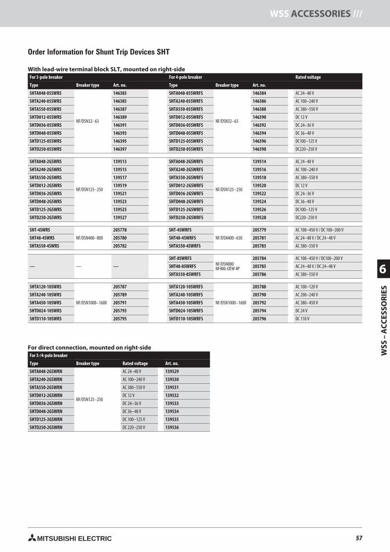
57MITSUBISHI ELECTRIC
WSS
–A
CC
ESSO
RIE
S
6
WSS ACCESSORIES ///
With lead-wire terminal block SLT, mounted on right-sideFor 3-pole breaker For 4-pole breaker Rated voltage
Type Breaker type Art. no. Type Breaker type Art. no.
SHTA048-05SWRS
NF/DSN32–63
146383 SHTA048-05SWRFS
NF/DSN32–63
146384 AC 24–48 V
SHTA240-05SWRS 146385 SHTA240-05SWRFS 146386 AC 100–240 V
SHTA550-05SWRS 146387 SHTA550-05SWRFS 146388 AC 380–550 V
SHTD012-05SWRS 146389 SHTD012-05SWRFS 146390 DC 12 V
SHTD036-05SWRS 146391 SHTD036-05SWRFS 146392 DC 24–36 V
SHTD048-05SWRS 146393 SHTD048-05SWRFS 146394 DC 36–48 V
SHTD125-05SWRS 146395 SHTD125-05SWRFS 146396 DC100–125 V
SHTD250-05SWRS 146397 SHTD250-05SWRFS 146398 DC220–250 V
SHTA048-2GSWRS
NF/DSN125–250
139513 SHTA048-2GSWRFS
NF/DSN125–250
139514 AC 24–48 V
SHTA240-2GSWRS 139515 SHTA240-2GSWRFS 139516 AC 100–240 V
SHTA550-2GSWRS 139517 SHTA550-2GSWRFS 139518 AC 380–550 V
SHTD012-2GSWRS 139519 SHTD012-2GSWRFS 139520 DC 12 V
SHTD036-2GSWRS 139521 SHTD036-2GSWRFS 139522 DC 24–36 V
SHTD048-2GSWRS 139523 SHTD048-2GSWRFS 139524 DC 36–48 V
SHTD125-2GSWRS 139525 SHTD125-2GSWRFS 139526 DC100–125 V
SHTD250-2GSWRS 139527 SHTD250-2GSWRFS 139528 DC220–250 V
SHT-4SWRS
NF/DSN400–800
205778 SHT-4SWRFS
NF/DSN400–630
205779 AC 100–450 V / DC 100–200 V
SHT48-4SWRS 205780 SHT48-4SWRFS 205781 AC 24–48 V / DC 24–48 V
SHTA550-4SWRS 205782 SHTA550-4SWRFS 205783 AC 380–550 V
— — —
SHT-8SWRFSNF/DSN800NF400-UEW 4P
205784 AC 100–450 V / DC100–200 V
SHT48-8SWRFS 205785 AC 24–48 V / DC 24–48 V
SHTA550-8SWRFS 205786 AC 380–550 V
SHTA120-10SWRS
NF/DSN1000–1600
205787 SHTA120-10SWRFS
NF/DSN1000–1600
205788 AC 100–120 V
SHTA240-10SWRS 205789 SHTA240-10SWRFS 205790 AC 200–240 V
SHTA450-10SWRS 205791 SHTA450-10SWRFS 205792 AC 380–450 V
SHTD024-10SWRS 205793 SHTD024-10SWRFS 205794 DC 24 V
SHTD110-10SWRS 205795 SHTD110-10SWRFS 205796 DC 110 V
For direct connection, mounted on right-sideFor 3-/4-pole breaker
Type Breaker type Rated voltage Art. no.
SHTA048-2GSWRN
NF/DSN125–250
AC 24–48 V 139529
SHTA240-2GSWRN AC 100–240 V 139530
SHTA550-2GSWRN AC 380–550 V 139531
SHTD012-2GSWRN DC 12 V 139532
SHTD036-2GSWRN DC 24–36 V 139533
SHTD048-2GSWRN DC 36–48 V 139534
SHTD125-2GSWRN DC 100–125 V 139535
SHTD250-2GSWRN DC 220–250 V 139536
Order Information for Shunt Trip Devices SHT
57neue Seiten_GB.prnLVS-Family - Technical SectionFreitag, 30. Januar 2009 14:18:57
Farbprofil: DeaktiviertKomposit Standardbildschirm
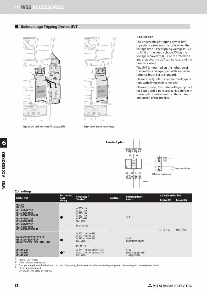
58 MITSUBISHI ELECTRIC
6
WSS
–A
CC
ESSO
RIE
S/// WSS ACCESSORIES
D1
P1
D3
P3
D2
P2
SO
UR
CE
Hi
Lo
Install and uninstall the
accessory in tripped position,
not in ON or OFF position
UVTSA-250GSWR
PAL70%50/60Hz
T
TsTL
IiIs
IrIp OVERIn 100A
Ii(X100A)xIr) TS(S) Ip(xIr)
10 .06.07 .10
.3 4
6
8 10
12
14
.1 .2
87
65
MITSUBISHI
OFF
J2J1
D2D2
D1D1
J1
J2
Contact plan
Install and uninstall the
accessory in tripped position,
not in ON or OFF position
UVTSA250-2GSWRN
PAL70%50/60Hz
T
TsTL
IiIs
IrIp OVERIn 100A
Ii(X100A)Ir) TS(S) Ip(xIr)
10 .06.07 .10
.3 4
6
8 10
12
14
.1 .2
87
6
Undervoltage Tripping Device UVT
Application
The undervoltage tripping device UVTtrips the breaker automatically when thevoltage drops. The tripping voltage is 35 %to 70 % of the rated voltage. When thevoltage recovers to 85 % of the rated volt-age or above, the UVT can be reset and thebreaker closed.
The UVT is mounted on the right side ofthe breaker and equipped with lead-wireterminal block SLT as standard.
Please specify, if left-side mounted type ortype with flying leads is needed.
Please consider, the undervoltage trip UVTfor 3-pole and 4-pole breaker is different inthe length of wires based on the outlinedimension of the breaker.
Coil ratings
Breaker type For synchro-nousclosing
Voltage (V)
Standard Input (VA) Operating time
(msec)Making/breaking data
Breaker OFF Breaker ON
NF32-SWNF63-SWNF125-SGW RT/RENF125-HGW RT/RENF125-RGW RT/UGW RTNF160-SGW RT/RENF160-HGW RT/RENF250-SGW RT/RENF250-HGW RT/RENF250-RGW RT/UGW RT
AC 100–120AC 200–240AC 220–240AC 380–450AC 400–440(50 / 60 Hz)
DC 24, DC 110
5
≤ 30
35–70 % UN min. 85 % UN
NF400-SEW / HEW / REW / UEWNF630-SEW / HEW / REWNF800-CEW / SEW / HEW / REW / UEW
AC 100–110/120–130AC 200–220/230–250AC 380–415/440–480(50 / 60 Hz)
DC100/110
5–30(Instantaneous type)
NF1000-SEWNF1250-SEWNF1600-SEW
AC 100–120/200–240/380–450AC 200–250/380–450/460–550(50 / 60 Hz)
5–35(Time delay type with3 voltage inputs)
Also for DSN types. Other voltages on request. The operating time is the time from the start of operating the breaker since the undervoltage trip went from voltage to no-voltage condition. DC version on request.
UVTs with Time delay on request.
Power control voltage
Breaker
UVT voltage control module
Figure shows Lead-wire terminal block type (SLT). Figure shows Internal terminal type.
58neue Seiten_GB.prnLVS-Family - Technical SectionFreitag, 30. Januar 2009 14:19:20
Farbprofil: DeaktiviertKomposit Standardbildschirm
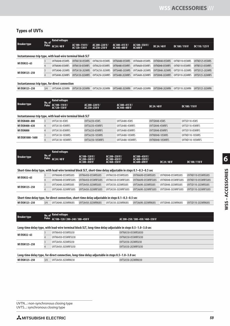
59MITSUBISHI ELECTRIC
WSS
–A
CC
ESSO
RIE
S
6
WSS ACCESSORIES ///
Breaker type No. ofPoles
Rated voltages
AC 24 / 48 V AC 100–110 V /AC 120–130 V
AC 200–220 V /AC 230–250 V
AC 380–415 V /AC 440–480 V
AC 500–550 V /AC 600 V DC 24 / 48 V DC 100 / 110 V DC 110 / 125 V
Instantaneous trip type, with lead-wire terminal block SLT
NF/DSN32–633 UVTNA048-05SWRS UVTNA130-05SWRS UVTNA250-05SWRS UVTNA480-05SWRS UVTNA600-05SWRS UVTND048-05SWRS UVTND110-05SWRS UVTND125-05SWRS
4 UVTNA048-05SWRFS UVTNA130-05SWRFS UVTNA250-05SWRFS UVTNA480-05SWRFS UVTNA600-05SWRFS UVTND048-05SWRFS UVTND110-05SWRFS UVTND125-05SWRFS
NF/DSN125–2503 UVTSA048-2GSWRS UVTSA130-2GSWRS UVTSA250-2GSWRS UVTSA480-2GSWRS UVTSA600-2GSWRS UVTSD048-2GSWRS UVTSD110-2GSWRS UVTSD125-2GSWRS
4 UVTSA048-2GSWRFS UVTSA130-2GSWRFS UVTSA250-2GSWRFS UVTSA480-2GSWRFS UVTSA600-2GSWRFS UVTSD048-2GSWRFS UVTSD110-2GSWRFS UVTSD125-2GSWRFS
Instantaneous trip type, for direct connectionNF/DSN125–250 3/4 UVTSA048-2GSWRN UVTSA130-2GSWRN UVTSA250-2GSWRN UVTSA480-2GSWRN UVTSA600-2GSWRN UVTSD048-2GSWRN UVTSD110-2GSWRN UVTSD125-2GSWRN
Breaker type No. ofPoles
Rated voltages
AC 100–110 V /AC 120–130 V
AC 200–220 V /AC 230–250 V
AC 380–415 V /AC 440–480 V DC 24 / 48 V DC 100 / 110 V
Instantaneous trip type, with lead-wire terminal block SLTNF/DSN400–800 3 UVTSA130-4SWS UVTSA250-4SWS UVTSA480-4SWS UVTSD048-4SWS UVTSD110-4SWS
NF/DSN400–630 4 UVTSA130-4SWRFS UVTSA250-4SWRFS UVTSA480-4SWRFS UVTSD048-4SWRFS UVTSD110-4SWRFS
NF/DSN800 4 UVTSA130-8SWRFS UVTSA250-8SWRFS UVTSA480-8SWRFS UVTSD048-8SWRFS UVTSD110-8SWRFS
NF/DSN1000–16003 UVTSA130-10SWRS UVTSA250-10SWRS UVTSA480-10SWRS UVTND048-10SWRS UVTND110-10SWRS
4 UVTSA130-10SWRFS UVTSA250-10SWRFS UVTSA480-10SWRFS UVTND048-10SWRFS UVTND110-10SWRFS
Breaker type No. ofPoles
Rated voltages
AC 24 / 48 VAC 100–120 V /AC 200–240 V /AC 380–450 V
AC 200–250 V /AC 380–450 V /AC 460–550 V
AC 380–450 V /AC 460–550 V /AC 600–690 V DC 24 / 48 V DC 100 / 110 V
Short-time delay type, with lead-wire terminal block SLT, short-time delay adjustable in steps 0.1–0.3–0.5 sec
NF/DSN32–633 UVTNA048-05SWRSU05 UVTNA450-05SWRSU05 UVTNA550-05SWRSU05 UVTNA690-05SWRSU05 UVTND048-05SWRSU05 UVTND110-05SWRSU05
4 UVTNA048-05SWRFSU05 UVTNA450-05SWRFSU05 UVTNA550-05SWRFSU05 UVTNA690-05SWRFSU05 UVTND048-05SWRFSU05 UVTND110-05SWRFSU05
NF/DSN125–2503 UVTSA048-2GSWRSU05 UVTSA450-2GSWRSU05 UVTSA550-2GSWRSU05 UVTSA690-2GSWRSU05 UVTSD048-2GSWRSU05 UVTSD110-2GSWRSU05
4 UVTSA048-2GSWRFSU05 UVTSA450-2GSWRFSU05 UVTSA550-2GSWRFSU05 UVTSA690-2GSWRFSU05 UVTSD048-2GSWRFSU05 UVTSD110-2GSWRFSU05
Short-time delay type, for direct connection, short-time delay adjustable in steps 0.1–0.3–0.5 secNF/DSN125–250 3/4 UVTSA048-2GSWRNU05 UVTSA450-2GSWRNU05 UVTSA550-2GSWRNU05 UVTSA690-2GSWRNU05 UVTSD048-2GSWRNU05 UVTSD110-2GSWRNU05
Breaker type No. ofPoles
Rated voltages
AC 100–120 / 200–240 / 380–450 V AC 200–250 / 380–450 / 460–550 V
Long-time delay type, with lead-wire terminal block SLT, long-time delay adjustable in steps 0.5–1.0–3.0 sec
NF/DSN32–633 UVTNA450-05SWRSU30 UVTNA550-05SWRSU030
4 UVTNA450-05SWRFSU30 UVTNA550-05SWRFSU30
NF/DSN125–2503 UVTSA450-2GSWRSU30 UVTSA550-2GSWRSU30
4 UVTSA450-2GSWRFSU30 UVTSA550-2GSWRFSU30
Long-time delay type, for direct connection, long-time delay adjustable in steps 0.5–1.0–3.0 secNF/DSN125–250 3/4 UVTSA450-2GSWRNU30 UVTSA550-2GSWRNU30
Types of UVTs
UVT ...: non-synchronous closing typeUVT ...: synchronous closing type
59neue Seiten_GB.prnLVS-Family - Technical SectionFreitag, 30. Januar 2009 14:19:25
Farbprofil: DeaktiviertKomposit Standardbildschirm
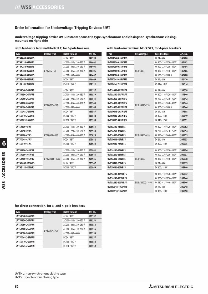
60 MITSUBISHI ELECTRIC
6
WSS
–A
CC
ESSO
RIE
S/// WSS ACCESSORIES
with lead-wire terminal block SLT, for 3-pole breakers
Type Breaker type Rated voltage Art. no.
UVTNA048-05SWRS
NF/DSN32–63
AC 24 / 48 V 146399
UVTNA130-05SWRS AC 100–110 / 120–130 V 146401
UVTNA250-05SWRS AC 200–220 / 230–250 V 146403
UVTNA480-05SWRS AC 380–415 / 440–480 V 146405
UVTNA600-05SWRS AC 500–550 / 600 V 146407
UVTND048-05SWRS DC 24 / 48 V 146409
UVTND125-05SWRS DC 110 / 125 V 146411
UVTSA048-2GSWRS
NF/DSN125–250
AC 24 / 48 V 139537
UVTSA130-2GSWRS AC 100–110 / 120–130 V 139539
UVTSA250-2GSWRS AC 200–220 / 230–250 V 139541
UVTSA480-2GSWRS AC 380–415 / 440–480 V 139543
UVTSA600-2GSWRS AC 500–550 / 600 V 139545
UVTSD048-2GSWRS DC 24 / 48 V 139547
UVTSD110-2GSWRS DC 100 / 110 V 139548
UVTSD125-2GSWRS DC 110 / 125 V 139550
UVTSA130-4SWS
NF/DSN400–800
AC 100–110 / 120–130 V 205951
UVTSA250-4SWS AC 200–220 / 230–250 V 205953
UVTSA480-4SWS AC 380–415 / 440–480 V 205828
UVTSD048-4SWS DC 24 / 48 V 205932
UVTSD110-4SWS DC 100 / 110 V 205934
UVTSA130-10SWRS
NF/DSN1000–1600
AC 100–110 / 120–130 V 205941
UVTSA250-10SWRS AC 200–220 / 230–250 V 205943
UVTSA480-10SWRS AC 380–415 / 440–480 V 205945
UVTND048-10SWRS DC 24 / 48 V 205947
UVTND110-10SWRS DC 100 / 110 V 205949
with lead-wire terminal block SLT, for 4-pole breakers
Type Breaker type Rated voltage Art. no.
UVTNA048-05SWRFS
NF/DSN 63
AC 24 / 48 V 146400
UVTNA130-05SWRFS AC 100–110 / 120–130 V 146402
UVTNA250-05SWRFS AC 200–220 / 230–250 V 146404
UVTNA480-05SWRFS AC 380–415 / 440–480 V 146406
UVTNA600-05SWRFS AC 500–550 / 600 V 146408
UVTND048-05SWRFS DC 24 / 48 V 146410
UVTND125-05SWRFS DC 110 / 125 V 146412
UVTSA048-2GSWRFS
NF/DSN125–250
AC 24 / 48 V 139538
UVTSA130-2GSWRFS AC 100–110 / 120–130 V 139540
UVTSA250-2GSWRFS AC 200–220 / 230–250 V 139542
UVTSA480-2GSWRFS AC 380–415 / 440–480 V 139544
UVTSA600-2GSWRFS AC 500–550 / 600 V 139546
UVTSD048-2GSWRFS DC 24 / 48 V 137508
UVTSD110-2GSWRFS DC 100 / 110 V 139549
UVTSD125-2GSWRFS DC 110 / 125 V 139551
UVTSA130-4SWRFS
NF/DSN400–630
AC 100–110 / 120–130 V 205952
UVTSA250-4SWRFS AC 200–220 / 230–250 V 205954
UVTSA480-4SWRFS AC 380–415 / 440–480 V 205955
UVTSD048-4SWRFS DC 24 / 48 V 205933
UVTSD110-4SWRFS DC 100 / 110 V 205935
UVTSA130-8SWRFS
NF/DSN800
AC 100–110 / 120–130 V 205936
UVTSA250-8SWRFS AC 200–220 / 230–250 V 205937
UVTSA480-8SWRFS AC 380–415 / 440–480 V 205938
UVTSD048-8SWRFS DC 24 / 48 V 205939
UVTSD110-8SWRFS DC 100 / 110 V 205940
UVTSA130-10SWRFS
NF/DSN1000–1600
AC 100–110 / 120–130 V 205942
UVTSA240-10SWRFS AC 200–220 / 230–250 V 205944
UVTSA480-10SWRFS AC 380–415 / 440–480 V 205946
UVTND048-10SWRFS DC 24 / 48 V 205948
UVTND110-10SWRFS DC 100 / 110 V 205950
Order Information for Undervoltage Tripping Devices UVT
Undervoltage tripping device UVT, instantaneous trip type, synchronous and closingnon-synchronous closing,mounted on right-side
Type Breaker type Rated voltage Art. no.
UVTSA048-2GSWRN
NF/DSN125–250
AC 24 / 48 V 139552
UVTSA130-2GSWRN AC 100–110 / 120–130 V 139553
UVTSA250-2GSWRN AC 200–220 / 230–250 V 139554
UVTSA480-2GSWRN AC 380–415 / 440–480 V 139555
UVTSA600-2GSWRN AC 500–550 / 600 V 139556
UVTSD048-2GSWRN DC 24 / 48 V 139557
UVTSD110-2GSWRN DC 100 / 110 V 139558
UVTSD125-2GSWRN DC 110 / 125 V 139559
for direct connection, for 3- and 4-pole breakers
for synchronous closing on requestUVT ...: non-synchronous closing typeUVT ...: synchronous closing type
60neue Seiten_GB.prnLVS-Family - Technical SectionFreitag, 30. Januar 2009 14:19:30
Farbprofil: DeaktiviertKomposit Standardbildschirm
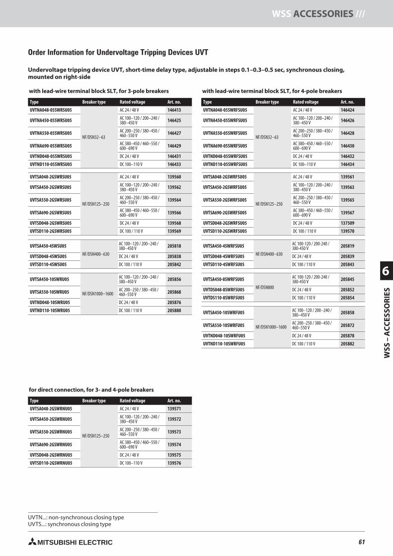
61MITSUBISHI ELECTRIC
WSS
–A
CC
ESSO
RIE
S
6
WSS ACCESSORIES ///
Order Information for Undervoltage Tripping Devices UVT
with lead-wire terminal block SLT, for 3-pole breakers
Type Breaker type Rated voltage Art. no.
UVTNA048-05SWRSU05
NF/DSN32–63
AC 24 / 48 V 146413
UVTNA450-05SWRSU05 AC 100–120 / 200–240 /380–450 V 146425
UVTNA550-05SWRSU05 AC 200–250 / 380–450 /460–550 V 146427
UVTNA690-05SWRSU05 AC 380–450 / 460–550 /600–690 V 146429
UVTND048-05SWRSU05 DC 24 / 48 V 146431
UVTND110-05SWRSU05 DC 100–110 V 146433
UVTSA048-2GSWRSU05
NF/DSN125–250
AC 24 / 48 V 139560
UVTSA450-2GSWRSU05 AC 100–120 / 200–240 /380–450 V 139562
UVTSA550-2GSWRSU05 AC 200–250 / 380–450 /460–550 V 139564
UVTSA690-2GSWRSU05 AC 380–450 / 460–550 /600–690 V 139566
UVTSD048-2GSWRSU05 DC 24 / 48 V 139568
UVTSD110-2GSWRSU05 DC 100 / 110 V 139569
UVTSA450-4SWSU05
NF/DSN400–630
AC 100–120 / 200–240 /380–450 V 205818
UVTSD048-4SWSU05 DC 24 / 48 V 205838
UVTSD110-4SWSU05 DC 100 / 110 V 205842
UVTSA450-10SWRU05
NF/DSN1000–1600
AC 100–120 / 200–240 /380–450 V 205856
UVTSA550-10SWRU05 AC 200–250 / 380–450 /460–550 V 205868
UVTND048-10SWRU05 DC 24 / 48 V 205876
UVTND110-10SWRU05 DC 100 / 110 V 205880
Undervoltage tripping device UVT, short-time delay type, adjustable in steps 0.1–0.3–0.5 sec, synchronous closing,mounted on right-side
with lead-wire terminal block SLT, for 4-pole breakers
Type Breaker type Rated voltage Art. no.
UVTNA048-05SWRFSU05
NF/DSN32–63
AC 24 / 48 V 146424
UVTNA450-05SWRFSU05 AC 100–120 / 200–240 /380–450 V 146426
UVTNA550-05SWRFSU05 AC 200–250 / 380–450 /460–550 V 146428
UVTNA690-05SWRFSU05 AC 380–450 / 460–550 /600–690 V 146430
UVTND048-05SWRFSU05 DC 24 / 48 V 146432
UVTND110-05SWRFSU05 DC 100–110 V 146434
UVTSA048-2GSWRFSU05
NF/DSN125–250
AC 24 / 48 V 139561
UVTSA450-2GSWRFSU05 AC 100–120 / 200–240 /380–450 V 139563
UVTSA550-2GSWRFSU05 AC 200–250 / 380–450 /460–550 V 139565
UVTSA690-2GSWRFSU05 AC 380–450 / 460–550 /600–690 V 139567
UVTSD048-2GSWRFSU05 DC 24 / 48 V 137509
UVTSD110-2GSWRFSU05 DC 100 / 110 V 139570
UVTSA450-4SWRFSU05
NF/DSN400–630
AC 100-120 / 200-240 /380-450 V 205819
UVTSD048-4SWRFSU05 DC 24 / 48 V 205839
UVTSD110-4SWRFSU05 DC 100 / 110 V 205843
UVTSA450-8SWRFSU05
NF/DSN800
AC 100-120 / 200-240 /380-450 V 205845
UVTDS048-8SWRFSU05 DC 24 / 48 V 205852
UVTDS110-8SWRFSU05 DC 100 / 110 V 205854
UVTSA450-10SWRFU05
NF/DSN1000–1600
AC 100–120 / 200–240 /380–450 V 205858
UVTSA550-10SWRFU05 AC 200–250 / 380–450 /460–550 V 205872
UVTND048-10SWRFU05 DC 24 / 48 V 205878
UVTND110-10SWRFU05 DC 100 / 110 V 205882
for direct connection, for 3- and 4-pole breakers
Type Breaker type Rated voltage Art. no.
UVTSA048-2GSWRNU05
NF/DSN125–250
AC 24 / 48 V 139571
UVTSA450-2GSWRNU05 AC 100–120 / 200–240 /380–450 V 139572
UVTSA550-2GSWRNU05 AC 200–250 / 380–450 /460–550 V 139573
UVTSA690-2GSWRNU05 AC 380–450 / 460–550 /600–690 V 139574
UVTSD048-2GSWRNU05 DC 24 / 48 V 139575
UVTSD110-2GSWRNU05 DC 100–110 V 139576
UVT ...: non-synchronous closing typeUVT ...: synchronous closing type
6161.prnLVS-Family - Technical SectionFreitag, 30. Januar 2009 14:35:31
Farbprofil: DeaktiviertKomposit Standardbildschirm
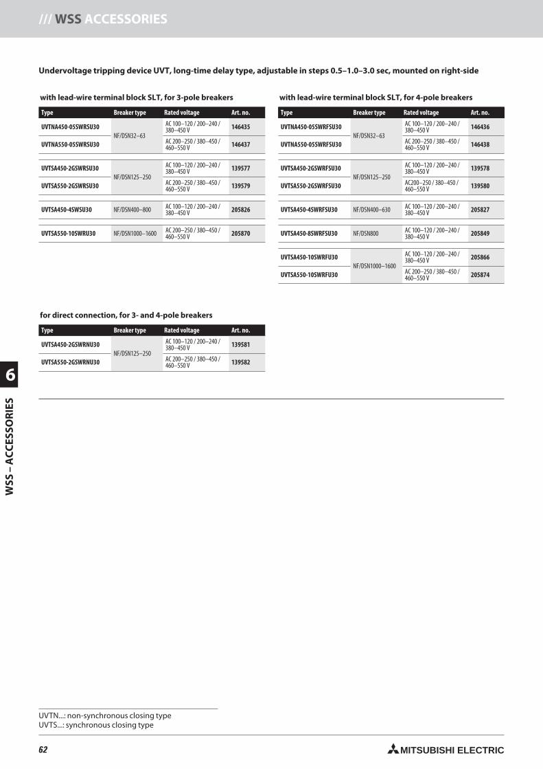
62 MITSUBISHI ELECTRIC
6
WSS
–A
CC
ESSO
RIE
S/// WSS ACCESSORIES
with lead-wire terminal block SLT, for 3-pole breakers
Type Breaker type Rated voltage Art. no.
UVTNA450-05SWRSU30NF/DSN32–63
AC 100–120 / 200–240 /380–450 V 146435
UVTNA550-05SWRSU30 AC 200–250 / 380–450 /460–550 V 146437
UVTSA450-2GSWRSU30NF/DSN125–250
AC 100–120 / 200–240 /380–450 V 139577
UVTSA550-2GSWRSU30 AC 200–250 / 380–450 /460–550 V 139579
UVTSA450-4SWSU30 NF/DSN400–800 AC 100–120 / 200–240 /380–450 V 205826
UVTSA550-10SWRU30 NF/DSN1000–1600 AC 200–250 / 380–450 /460–550 V 205870
with lead-wire terminal block SLT, for 4-pole breakers
Type Breaker type Rated voltage Art. no.
UVTNA450-05SWRFSU30NF/DSN32–63
AC 100–120 / 200–240 /380–450 V 146436
UVTNA550-05SWRFSU30 AC 200–250 / 380–450 /460–550 V 146438
UVTSA450-2GSWRFSU30NF/DSN125–250
AC 100–120 / 200–240 /380–450 V 139578
UVTSA550-2GSWRFSU30 AC200–250 / 380–450 /460–550 V 139580
UVTSA450-4SWRFSU30 NF/DSN400–630 AC 100–120 / 200–240 /380–450 V 205827
UVTSA450-8SWRFSU30 NF/DSN800 AC 100–120 / 200–240 /380–450 V 205849
UVTSA450-10SWRFU30NF/DSN1000–1600
AC 100–120 / 200–240 /380–450 V 205866
UVTSA550-10SWRFU30 AC 200–250 / 380–450 /460–550 V 205874
Undervoltage tripping device UVT, long-time delay type, adjustable in steps 0.5–1.0–3.0 sec, mounted on right-side
for direct connection, for 3- and 4-pole breakers
Type Breaker type Rated voltage Art. no.
UVTSA450-2GSWRNU30NF/DSN125–250
AC 100–120 / 200–240 /380–450 V 139581
UVTSA550-2GSWRNU30 AC 200–250 / 380–450 /460–550 V 139582
UVT ...: non-synchronous closing typeUVT ...: synchronous closing type
62neue Seiten_GB.prnLVS-Family - Technical SectionFreitag, 30. Januar 2009 14:19:37
Farbprofil: DeaktiviertKomposit Standardbildschirm
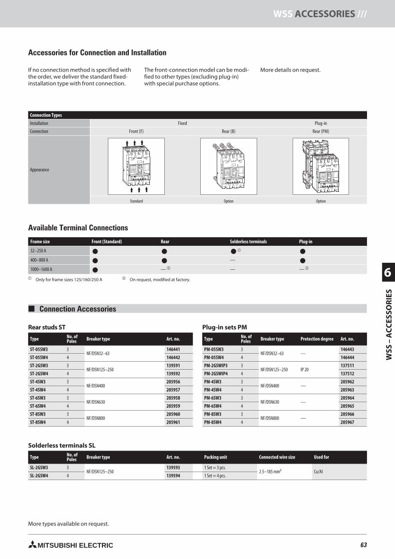
63MITSUBISHI ELECTRIC
WSS
–A
CC
ESSO
RIE
S
6
WSS ACCESSORIES ///
Accessories for Connection and Installation
If no connection method is specified withthe order, we deliver the standard fixed-installation type with front connection.
The front-connection model can be modi-fied to other types (excluding plug-in)with special purchase options.
More details on request.
Connection Types
Installation Fixed Plug-in
Connection Front (F) Rear (B) Rear (PM)
Appearance
Standard Option Option
MITSUBISHI OFF
ON
NO-FUSE BREAKER
NF125-SGW
In A100Ir 63-100A
MODEL
POLE
Ui690V
Cat.A
PUSH TO TRIP
Uimp 8kV
3 P
IEC60947-2
JIS C 8201-2
Ue690VAC
525VAC
500VAC
440VAC
380/415VAC
230VAC
300VAC
EN60947-2
40°C
Icu/Ics
8/8kA
22/22kA
30/30kA
36/36kA
36/36kA
85/85kA
20/20kA
MITSUBISHI ELECTRIC
PAL70%50/60Hz
T
TsTL
IiIs
IrIp
Ii(X100A)
Ir(A) TL(S) IS(xIr) TS(S) Ip(xIr)
63 100 10012 22.5
10 .06.07 .10
.3 4
6
8 10
12
14
.1 .2
87
65480 3.53
60 80
OVERMODEL
RE100 In 100A
Rear studs ST
Type No. ofPoles Breaker type Art. no.
ST-05SW3 3NF/DSN32–63
146441
ST-05SW4 4 146442
ST-2GSW3 3NF/DSN125–250
139591
ST-2GSW4 4 139592
ST-4SW3 3NF/DSN400
205956
ST-4SW4 4 205957
ST-6SW3 3NF/DSN630
205958
ST-6SW4 4 205959
ST-8SW3 3NF/DSN800
205960
ST-8SW4 4 205961
Plug-in sets PM
Type No. ofPoles Breaker type Protection degree Art. no.
PM-05SW3 3NF/DSN32–63 —
146443
PM-05SW4 4 146444
PM-2GSWIP3 3NF/DSN125–250 IP 20
137511
PM-2GSWIP4 4 137512
PM-4SW3 3NF/DSN400 —
205962
PM-4SW4 4 205963
PM-6SW3 3NF/DSN630 —
205964
PM-6SW4 4 205965
PM-8SW3 3NF/DSN800 —
205966
PM-8SW4 4 205967
Connection Accessories
More types available on request.
Frame size Front (Standard) Rear Solderless terminals Plug-in
32–250 A
400–800 A —
1000–1600 A — — —
Only for frame sizes 125/160/250 A On request, modified at factory.
Available Terminal Connections
Solderless terminals SL
Type No. ofPoles Breaker type Art. no. Packing unit Connected wire size Used for
SL-2GSW3 3NF/DSN125–250
139593 1 Set = 3 pcs.2.5–185 mm² Cu/Al
SL-2GSW4 4 139594 1 Set = 4 pcs.
63neue Seiten_GB.prnLVS-Family - Technical SectionFreitag, 30. Januar 2009 14:20:13
Farbprofil: DeaktiviertKomposit Standardbildschirm
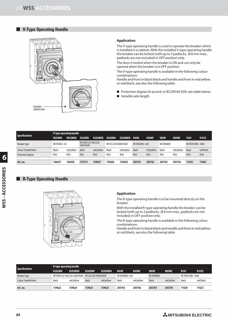
64 MITSUBISHI ELECTRIC
6
WSS
–A
CC
ESSO
RIE
S/// WSS ACCESSORIES
MITSUBISHI OFF
ON
NO-FUSE BREAKER
NF125-SGW
In A100Ir 63-100A
MODEL
POLE
Ui690V
Cat.A
PUSH TO TRIP
Uimp 8kV
3 P
IEC60947-2
JIS C 8201-2
Ue690VAC
525VAC
500VAC
440VAC
380/415VAC
230VAC
300VAC
EN60947-2
40°C
Icu/Ics
8/8kA
22/22kA
30/30kA
36/36kA
36/36kA
85/85kA
20/20kA
MITSUBISHI ELECTRIC
PAL70%50/60Hz
T
TsTL
IiIs
IrIp
Ii(X100A)
Ir(A) TL(S) IS(xIr) TS(S) Ip(xIr)
63 100 10012 22.5
10 .06.07 .10
.3 4
6
8 10
12
14
.1 .2
87
65480 3.53
60 80
OVERMODEL
RE100 In 100A
RESET
OFF
TRIP
PED
PUSHTOTRIP
ON
MITSUBISHI OFF
ON
NO-FUSE BREAKER
NF125-SGW
In A100Ir 63-100A
MODEL
POLE
Ui690V
Cat.A
PUSH TO TRIP
Uimp 8kV
3 P
IEC60947-2
JIS C 8201-2
Ue690VAC
525VAC
500VAC
440VAC
380/415VAC
230VAC
300VAC
EN60947-2
40°C
Icu/Ics
8/8kA
22/22kA
30/30kA
36/36kA
36/36kA
85/85kA
20/20kA
MITSUBISHI ELECTRIC
PAL70%50/60Hz
T
TsTL
IiIs
IrIp
Ii(X100A)
Ir(A) TL(S) IS(xIr) TS(S) Ip(xIr)
63 100 10012 22.5
10 .06.07 .10
.3 4
6
8 10
12
14
.1 .2
87
65480 3.53
60 80
OVERMODEL
RE100 In 100ARESET
OFF
TRIP
PED
PUSHTOTRIP
ON
V-Type Operating Handle
Application
The V-type operating handle is used to operate the breaker whichis installed in a cabinet. With the installed V-type operating handlethe breaker can be locked (with up to 3 padlocks, Ø 8 mm max.,padlocks are not included) in OFF position only.
The door is locked when the breaker is ON and can only beopened when the breaker is in OFF position.
The V-type operating handle is available in the following colourcombinations:Handle and front in black/black and handle and front in red/yellow,or red/black, see also the following table.
Protection degree (in accord. to IEC/EN 60 529): see table below. Variable axle length.
SpecificationsV-type operating handle
V05SWN V05SWEN V2GSWN V2GSWEN V2GUWN V2GUWEN V4SW V4SWE V8SW V8SWE V101 V101E
Breaker type NF/DSN32–63 NF/DSN125/160/250-SGW/HGW NF125/250-RGW/UGW NF/DSN400–630 NF/DSN800 NF/DSN1000–1600
Colour: handle/front black red/yellow black red/yellow black red/yellow black red/yellow black red/yellow black red/black
Protection degree IP65 IP65 IP65 IP65 IP65 IP65 IP65 IP65 IP65 IP65 IP50 IP50
Art. no. 146457 146458 137513 139627 139626 139628 203761 203762 203763 203764 11659 11663
R-Type Operating Handle
Application
The R-type operating handle is to be mounted directly on thebreaker.
With the installed R-type operating handle the breaker can belocked (with up to 3 padlocks, Ø 8 mm max., padlocks are notincluded) in OFF position only.
The R-type operating handle is available in the following colourcombinations:Handle and front in black/black and handle and front in red/yellow,or red/black, see also the following table.
SpecificationsR-type operating handle
R2GSWN R2GSWEN R2GUWN R2GUWEN R4SW R4SWE R8SW R8SWE R101 R101E
Breaker type NF/DSN125/160/250-SGW/HGW NF125/250-RGW/UGW NF/DSN400–630 NF/DSN800 NF/DSN1000–1600
Colour: handle/front black red/yellow black red/yellow black red/yellow black red/yellow black red/black
Art. no. 139622 139624 139623 139625 203765 203766 203767 203769 11620 11623
Example:cabinet door
64neue Seiten_GB.prnLVS-Family - Technical SectionFreitag, 30. Januar 2009 14:21:02
Farbprofil: DeaktiviertKomposit Standardbildschirm
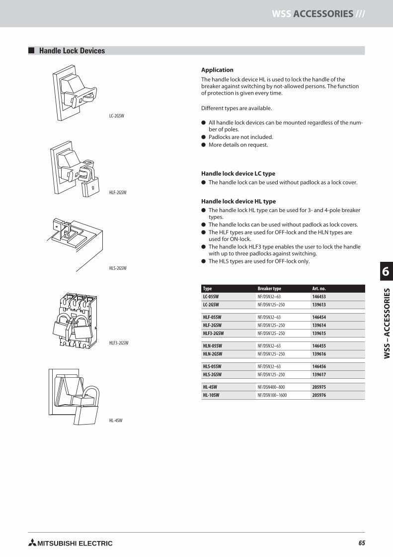
65MITSUBISHI ELECTRIC
WSS
–A
CC
ESSO
RIE
S
6
WSS ACCESSORIES ///
LC-2GSW
HLF-2GSW
HLF3-2GSW
HLS-2GSW
HL-4SW
Handle Lock Devices
Application
The handle lock device HL is used to lock the handle of thebreaker against switching by not-allowed persons. The functionof protection is given every time.
Different types are available.
All handle lock devices can be mounted regardless of the num-ber of poles.
Padlocks are not included. More details on request.
Handle lock device LC type The handle lock can be used without padlock as a lock cover.
Handle lock device HL type The handle lock HL type can be used for 3- and 4-pole breaker
types. The handle locks can be used without padlock as lock covers. The HLF types are used for OFF-lock and the HLN types are
used for ON-lock. The handle lock HLF3 type enables the user to lock the handle
with up to three padlocks against switching. The HLS types are used for OFF-lock only.
Type Breaker type Art. no.
LC-05SW NF/DSN32–63 146453
LC-2GSW NF/DSN125–250 139613
HLF-05SW NF/DSN32–63 146454
HLF-2GSW NF/DSN125–250 139614
HLF3-2GSW NF/DSN125–250 139615
HLN-05SW NF/DSN32–63 146455
HLN-2GSW NF/DSN125–250 139616
HLS-05SW NF/DSN32–63 146456
HLS-2GSW NF/DSN125–250 139617
HL-4SW NF/DSN400–800 205975
HL-10SW NF/DSN100–1600 205976
65neue Seiten_GB.prnLVS-Family - Technical SectionFreitag, 30. Januar 2009 14:21:20
Farbprofil: DeaktiviertKomposit Standardbildschirm
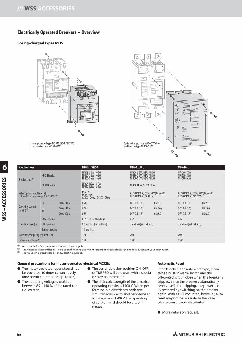
66 MITSUBISHI ELECTRIC
6
WSS
–A
CC
ESSO
RIE
S/// WSS ACCESSORIES
MITSUBISHI OFF
ON
NO-FUSE BREAKER
NF125-SGW
In A100Ir 63-100A
MODEL
POLE
Ui690V
Cat.A
PUSH TO TRIP
Uimp 8kV
3 P
IEC60947-2
JIS C 8201-2
Ue690VAC
525VAC
500VAC
440VAC
380/415VAC
230VAC
300VAC
EN60947-2
40°C
Icu/Ics
8/8kA
22/22kA
30/30kA
36/36kA
36/36kA
85/85kA
20/20kA
MITSUBISHI ELECTRIC
PAL70%50/60Hz
T
TsTL
IiIs
IrIp OVERMODEL
RE100 In 100A
ON
MITSUBISHI ELECTRIC
Uc
Push to
(MANU)
NO-FUSE BREAKER
NF250-SGW
MSDBA-NF25GSW
A0106
MODEL
Push
Pull
MODEL
SERIAL:
Ui 690V
Cat.A
IEC60947-2
JIS C 8201-2
Ue690VAC
525VAC
500VAC
440VAC
380/415VAC
230VAC
MANU
AUTO
RATED CURRENT
250 A
Uimp 8kV
EN60947-2
40°C
Icu/Ics
8/8kA
22/22kA
30/30kA
36/36kA
36/36kA
85/85kA
50/60Hz
Push toOPEN
(TRIP)
ON
Dis-charge
Control circuitvoltage should besupplied to P1and P2 terminals.
P1 P2 S1 S2 S4
MITSUBISHIPOWER SUPPLY MODULE
MODEL MDSPSA240-SW
CONTROLL CIRCUIT VOLTAGE
AC100-240V/DC100-250V
S4OperatingCircuit S2
P2S1
P1
P1P2S1S2S4
Uc
ON
K3
K2
K2
K1K1
SW1K3
K3
K2
K1
PowerSupply
OFF
Ii(X100A)
Ir(A) TL(S) IS(xIr) TS(S) Ip(xIr)
63 100 10012 22.5
10 .06.07 .10
.3 4
6
8 10
12
14
.1 .2
87
65480 3.53
60 80
JISUe550VAC
460VAC
220VAC
IEC 60947-2
EN 60947-2
500VAC250VAC
Icn
35kA
50kA
85kA
Icu/Ics
10/10kA30/30kA42/42kA45/45kA85/85kA
40°C
50kA85kA
MITSUBISHI ELECTRIC
OFF
ON
MITSUBISHINO-FUSE BREAKER
NF400-SEP
400A
400
MODEL
POLE
Ui 690VAC
50 - 60Hz
8kV
PUSH TO TRIP
Uimp
3 P
Ip(xIr)
TEST
TL(sec) TS(sec)10012
60 80IS(xIr)
22.5
108
765300
3504
3.53
.06 .3
.1 .2Ii(X400A)
4
6
8 10
12
1614
.07 .10
Ir(A)200
220
250
400
T
TsTL
IiIs
IrIp
Ip(xIr)Ip(xIr)
TESTTEST
TL(sec)TL(sec) TS(sec)TS(sec)1001001212
6060 8080IS(xIr)IS(xIr)
222.52.5
101088
776655300300
35035044
3.53.533
.06.06 .3.3
.1.1 .2.2Ii(X400A)Ii(X400A)
44
66
88 1010
1212
16161414
.07.07 .10.10
Ir(A)Ir(A)200200
220220
250250
400400
T
TsTL
IiIs
IrIp
OFF
Electrically Operated Breakers – Overview
Spring-charged types MDS
Specifications MDSD.../MDSA... MDS-4.../8... MDS-16...
Breaker type
NF-S/H seriesNF125-SGW / HGWNF160-SGW / HGWNF250-SGW / HGW
NF400-SEW / HEW / REWNF630-SEW / HEW / REWNF800-SEW / HEW / REW
NF1000-SEWNF1250-SEWNF1600-SEW
NF-R/U series NF125-RGW / UGWNF250-RGW / UGW NF400-UEW, NF800-UEW —
Rated operating voltage (V)(allowable voltage range 85–110%)
DC 24 VDC48–60VAC100–240V / DC100–250V
AC 100/110 V, 200/220 V (AC 240 V)DC 100/110 V (DC 125 V)
AC 100/110 V, 200/220 V (AC 240 V)DC 100/110 V (DC125 V)
Operating current(A, eff.)
DC 100 / 110 V 0.20 OFF: 1.0 (3.0) ON: 8.0 OFF: 1.0 (3.0) ON: 9.0
AC100 / 110 V 0.50 OFF: 1.0 (3.0) ON: 10.0 OFF: 1.0 (3.0) ON: 10.0
200 / 200 V 0.35 OFF: 0.5 (1.5) ON: 8.0 OFF: 0.5 (1.5) ON: 8.0
Operating time (sec.)
ON operating 0.05–0.1 (self holding) 0.05 0.07
OFF operating 0.6 and less (self holding) 3 and less (self holding) 3 and less (self holding)
Spring charging 1.2 and less — —
Transformer capacity required (VA) 150 700 700
Endurance voltage (V) 1500 1500 1500
Also usable for Disconnectors DSN with 3 and 4 poles. The voltages in parentheses ( ) are special options and might require an external resistor. For details, consult your distributor. The values in parentheses ( ) show starting current.
General precautions for motor-operated electrical MCCBs The motor operated types should not
be operated 10 times consecutively(one on/off counts as an operation).
The operating voltage should bebetween 85 – 110 % of the rated con-trol voltage.
The current breaker position ON, OFFor TRIPPED will be shown with a specialdisplay on the motor.
The dielectric strength of the electricaloperating circuits is 1500 V. When per-forming a dielectric strength testsimultaneously with another device ata voltage over 1500 V, the operatingcircuit terminal should be discon-nected.
Automatic Reset
If the breaker is an auto reset type, it con-tains a built-in alarm switch and theoff-control circuit close when the breaker istripped. Since the breaker automaticallyresets itself after tripping, the power is eas-ily restored by switching on the breakeragain. With a UVT mounted, however, autoreset may not be possible. In this case,please consult your distributor.
More details on request.
Spring-charged type MDS-4SWA110and breaker type NF400-SEW
Spring-charged type MDSAD240-NF2GSWEand breaker type NF250-SGW
66neue Seiten_GB.prnLVS-Family - Technical SectionFreitag, 30. Januar 2009 14:21:54
Farbprofil: DeaktiviertKomposit Standardbildschirm
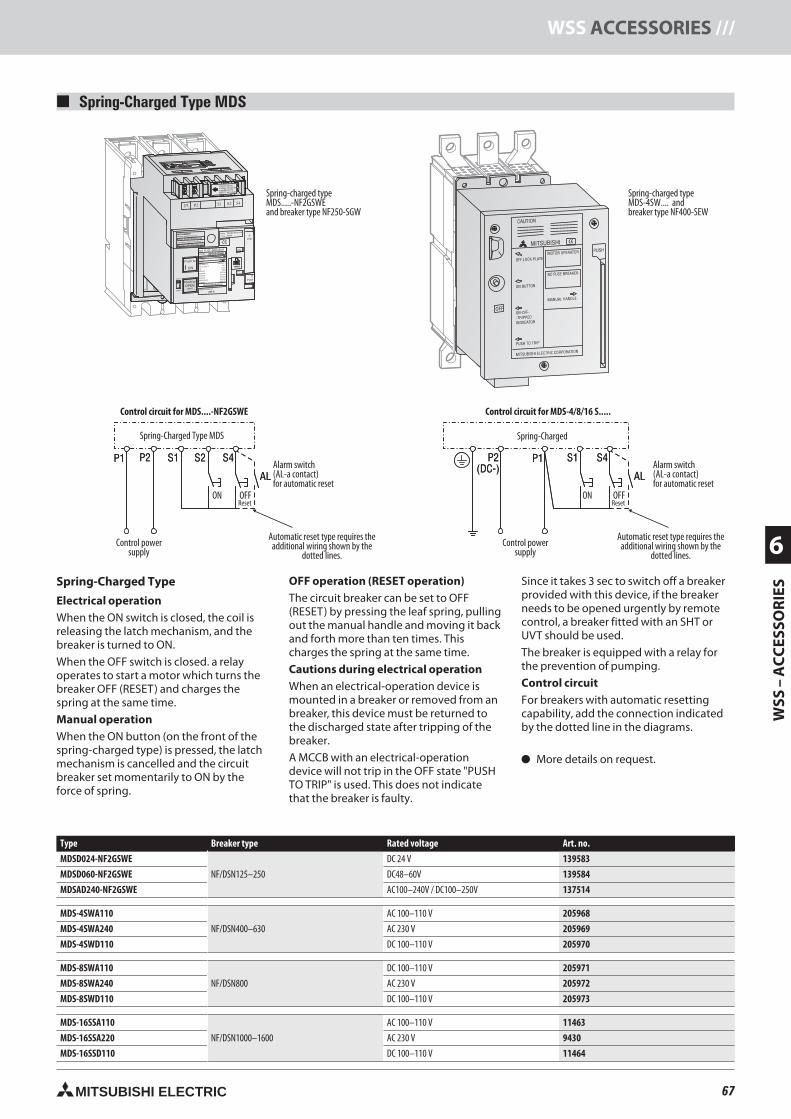
67MITSUBISHI ELECTRIC
WSS
–A
CC
ESSO
RIE
S
6
WSS ACCESSORIES ///
MITSUBISHI OFF
ON
NO-FUSE BREAKER
NF125-SGW
In A100Ir 63-100A
MODEL
POLE
Ui690V
Cat.A
PUSH TO TRIP
Uimp 8kV
3 P
IEC60947-2
JIS C 8201-2
Ue690VAC
525VAC
500VAC
440VAC
380/415VAC
230VAC
300VAC
EN60947-2
40°C
Icu/Ics
8/8kA
22/22kA
30/30kA
36/36kA
36/36kA
85/85kA
20/20kA
MITSUBISHI ELECTRIC
PAL70%50/60Hz
T
TsTL
IiIs
IrIp OVERMODEL
RE100 In 100A
Ii(X100A)
Ir(A) TL(S) IS(xIr) TS(S) Ip(xIr)
63 100 10012 22.5
10 .06.07 .10
.3 4
6
8 10
12
14
.1 .2
87
65480 3.53
60 80
ON
MITSUBISHI ELECTRIC
Uc
Push to
(MANU)
NO-FUSE BREAKER
NF250-SGW
MSDBA-NF25GSW
A0106
MODEL
Push
Pull
MODEL
SERIAL:
Ui 690V
Cat.A
IEC60947-2
JIS C 8201-2
Ue690VAC
525VAC
500VAC
440VAC
380/415VAC
230VAC
MANU
AUTO
RATED CURRENT
250 A
Uimp 8kV
EN60947-2
40°C
Icu/Ics
8/8kA
22/22kA
30/30kA
36/36kA
36/36kA
85/85kA
50/60Hz
Push toOPEN
(TRIP)
ON
Dis-charge
Control circuitvoltage should besupplied to P1and P2 terminals.
P1 P2 S1 S2 S4
MITSUBISHIPOWER SUPPLY MODULE
MODEL MDSPSA240-SW
CONTROLL CIRCUIT VOLTAGE
AC100-240V/DC100-250V
S4OperatingCircuit S2
P2S1
P1
P1P2S1S2S4
Uc
ON
K3
K2
K2
K1K1
SW1K3
K3
K2
K1
PowerSupply
OFF
JISUe550VAC
460VAC
220VAC
IEC 60947-2
EN 60947-2
500VAC250VAC
Icn
35kA
50kA
85kA
Icu/Ics
10/10kA30/30kA42/42kA45/45kA85/85kA
40°C
50kA85kA
MITSUBISHI ELECTRIC
OFF
ON
MITSUBISHINO-FUSE BREAKER
NF400-SEP
400A
400
MODEL
POLE
Ui 690VAC
50 - 60Hz
8kV
PUSH TO TRIP
Uimp
3 P
Ip(xIxIr)
TEST
TL(sesec)c) TS(sesec)c)10012
60 80IS(xIxIr)
22.5
108
765300
3504
3.53
.06 .3
.1 .2Ii(X400A)
4
6
8 10
12
1614
.07 .10
Ir(A)200
220
250
400
T
TsTL
IiIs
IrIp
Ip(xIr)Ip(xIr)
TESTTEST
TL(sec)TL(sec) TS(sec)TS(sec)1001001212
6060 8080IS(xIr)IS(xIr)
222.52.5
101088
776655300300
35035044
3.53.533
.06.06 .3.3
.1.1 .2.2Ii(X400A)Ii(X400A)
44
66
88 1010
1212
16161414
.07.07 .10.10
Ir(A)Ir(A)200200
220220
250250
400400
T
TsTL
IiIs
IrIp
OFF
OFF
OFF
OFF
S1P1P2(DC-)
S4
AL
S2P1 P2 S4
AL
S1
Spring-Charged Type MDS
Type Breaker type Rated voltage Art. no.
MDSD024-NF2GSWE
NF/DSN125–250
DC 24 V 139583
MDSD060-NF2GSWE DC48–60V 139584
MDSAD240-NF2GSWE AC100–240V / DC100–250V 137514
MDS-4SWA110
NF/DSN400–630
AC 100–110 V 205968
MDS-4SWA240 AC 230 V 205969
MDS-4SWD110 DC 100–110 V 205970
MDS-8SWA110
NF/DSN800
DC 100–110 V 205971
MDS-8SWA240 AC 230 V 205972
MDS-8SWD110 DC 100–110 V 205973
MDS-16SSA110
NF/DSN1000–1600
AC 100–110 V 11463
MDS-16SSA220 AC 230 V 9430
MDS-16SSD110 DC 100–110 V 11464
Spring-charged typeMDS.....-NF2GSWEand breaker type NF250-SGW
Spring-charged typeMDS-4SW.... andbreaker type NF400-SEW
Automatic reset type requires theadditional wiring shown by the
dotted lines.Control power
supply
S1P1P2(DC-)
S4
AL
Control circuit for MDS-4/8/16 S.....Control circuit for MDS....-NF2GSWE
S2P1 P2 S4
AL
S1Alarm switch(AL-a contact)for automatic reset
Alarm switch(AL-a contact)for automatic reset
Automatic reset type requires theadditional wiring shown by the
dotted lines.Control power
supply
OFFReset
Spring-Charged Type
Electrical operationWhen the ON switch is closed, the coil isreleasing the latch mechanism, and thebreaker is turned to ON.
When the OFF switch is closed. a relayoperates to start a motor which turns thebreaker OFF (RESET) and charges thespring at the same time.
Manual operationWhen the ON button (on the front of thespring-charged type) is pressed, the latchmechanism is cancelled and the circuitbreaker set momentarily to ON by theforce of spring.
OFF operation (RESET operation)The circuit breaker can be set to OFF(RESET) by pressing the leaf spring, pullingout the manual handle and moving it backand forth more than ten times. Thischarges the spring at the same time.
Cautions during electrical operationWhen an electrical-operation device ismounted in a breaker or removed from anbreaker, this device must be returned tothe discharged state after tripping of thebreaker.
A MCCB with an electrical-operationdevice will not trip in the OFF state "PUSHTO TRIP" is used. This does not indicatethat the breaker is faulty.
Since it takes 3 sec to switch off a breakerprovided with this device, if the breakerneeds to be opened urgently by remotecontrol, a breaker fitted with an SHT orUVT should be used.
The breaker is equipped with a relay forthe prevention of pumping.
Control circuitFor breakers with automatic resettingcapability, add the connection indicatedby the dotted line in the diagrams.
More details on request.
ON OFFReset
ON
Spring-Charged Type MDS Spring-Charged
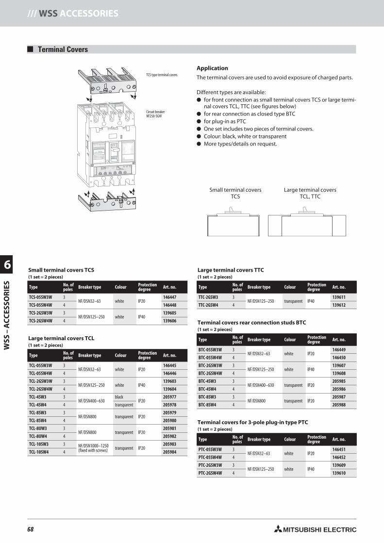
68 MITSUBISHI ELECTRIC
6
WSS
–A
CC
ESSO
RIE
S/// WSS ACCESSORIES
Terminal Covers
Application
The terminal covers are used to avoid exposure of charged parts.
Different types are available: for front connection as small terminal covers TC or large termi-
nal covers TC , TTC (see figures below) for rear connection as closed type BTC for plug-in as PTC One set includes two pieces of terminal covers. Colour: black, white or transparent More types/details on request.MITSUBISHI OFF
ON
NO-FUSE BREAKER
NF125-SGW
In A100Ir 63-100A
MODEL
POLE
Ui690V
Cat.A
PUSH TO TRIP
Uimp 8kV
3 P
IEC60947-2
JIS C 8201-2
Ue690VAC
525VAC
500VAC
440VAC
380/415VAC
230VAC
300VAC
EN60947-2
40°C
Icu/Ics
8/8kA
22/22kA
30/30kA
36/36kA
36/36kA
85/85kA
20/20kA
MITSUBISHI ELECTRIC
PAL70%50/60Hz
T
TsTL
IiIs
IrIp
Ii(X100A)
Ir(A) TL(S) IS(xIr) TS(S) Ip(xIr)
63 100 10012 22.5
10 .06.07 .10
.3 4
6
8 10
12
14
.1 .2
87
65480 3.53
60 80
OVERMODEL
RE100 In 100A
Small terminal coversTCS
Large terminal coversTCL, TTC
TCS type terminal covers
Circuit breakerNF250-SGW
Small terminal covers TCS(1 set = 2 pieces)
Type No. ofpoles Breaker type Colour Protection
degree Art. no.
TCS-05SW3W 3NF/DSN32–63 white IP20
146447
TCS-05SW4W 4 146448
TCS-2GSW3W 3NF/DSN125–250 white IP40
139605
TCS-2GSW4W 4 139606
Large terminal covers TCL(1 set = 2 pieces)
Type No. ofpoles Breaker type Colour Protection
degree Art. no.
TCL-05SW3W 3NF/DSN32–63 white IP20
146445
TCL-05SW4W 4 146446
TCL-2GSW3W 3NF/DSN125–250 white IP40
139603
TCL-2GSW4W 4 139604
TCL-4SW3 3NF/DSN400–630
blackIP20
205977
TCL-4SW4 4 transparent 205978
TCL-8SW3 3NF/DSN800 transparent IP20
205979
TCL-8SW4 4 205980
TCL-8UW3 3NF/DSN800 transparent IP20
205981
TCL-8UW4 4 205982
TCL-10SW3 3 NF/DSN1000–1250(fixed with screws) transparent IP20
205983
TCL-10SW4 4 205984
Large terminal covers TTC(1 set = 2 pieces)
Type No. ofpoles Breaker type Colour Protection
degree Art. no.
TTC-2GSW3 3NF/DSN125–250 transparent IP40
139611
TTC-2GSW4 4 139612
Terminal covers rear connection studs BTC(1 set = 2 pieces)
Type No. ofpoles Breaker type Colour Protection
degree Art. no.
BTC-05SW3W 3NF/DSN32–63 white IP20
146449
BTC-05SW4W 4 146450
BTC-2GSW3W 3NF/DSN125–250 white IP40
139607
BTC-2GSW4W 4 139608
BTC-4SW3 3NF/DSN400–630 transparent IP20
205985
BTC-4SW4 4 205986
BTC-8SW3 3NF/DSN800 transparent IP20
205987
BTC-8SW4 4 205988
Terminal covers for 3-pole plug-in type PTC(1 set = 2 pieces)
Type No. ofpoles Breaker type Colour Protection
degree Art. no.
PTC-05SW3W 3NF/DSN32–63 white IP20
146451
PTC-05SW4W 4 146452
PTC-2GSW3W 3NF/DSN125–250 white IP40
139609
PTC-2GSW4W 4 139610
68neue Seiten_GB.prnLVS-Family - Technical SectionFreitag, 30. Januar 2009 14:23:02
Farbprofil: DeaktiviertKomposit Standardbildschirm
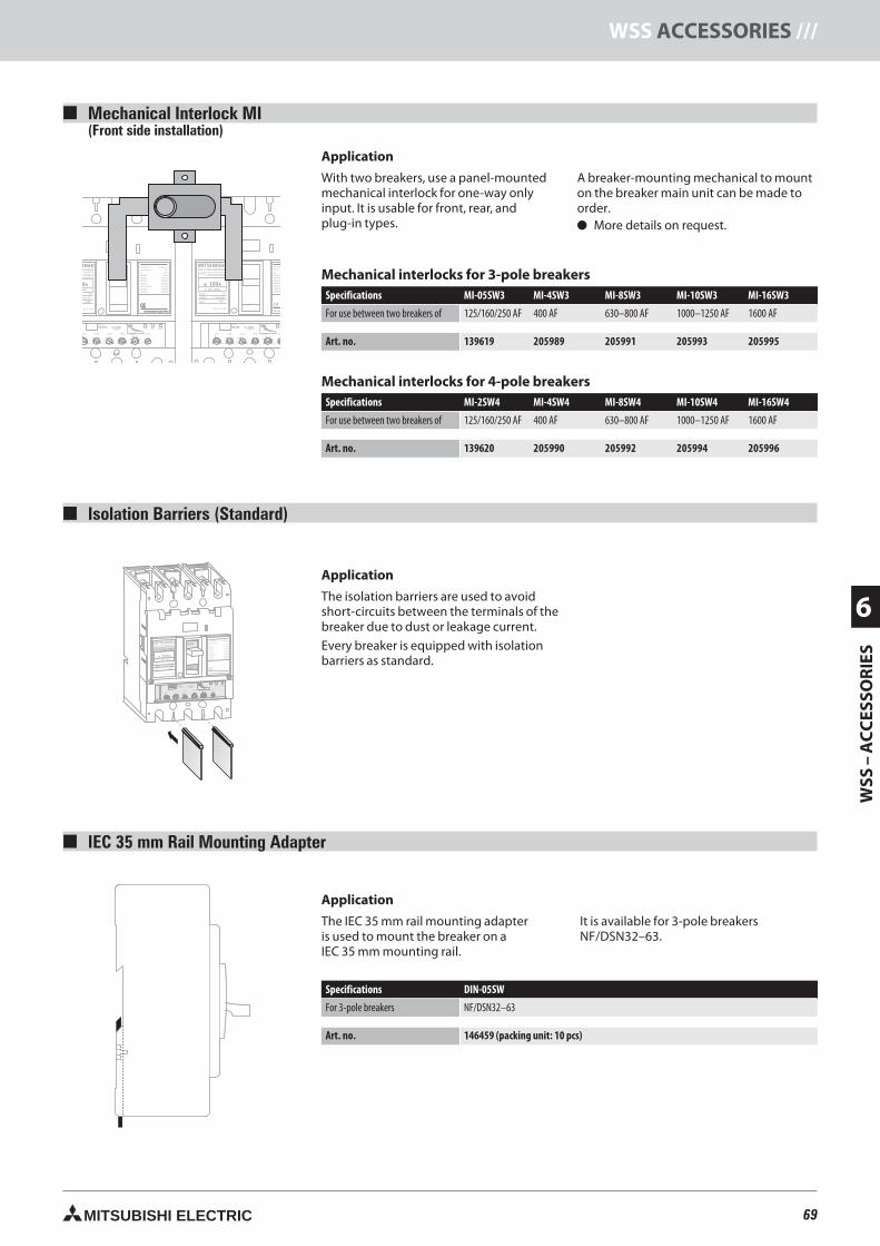
69MITSUBISHI ELECTRIC
WSS
–A
CC
ESSO
RIE
S
6
WSS ACCESSORIES ///
MITSUBISHI OFF
ON
NO-FUSE BREAKER
NF125-SGW
In A100Ir 63-100A
MODEL
POLE
Ui690V
Cat.A
PUSH TO TRIP
Uimp 8kV
3 P
IEC60947-2
JIS C 8201-2
Ue690VAC
525VAC
500VAC
440VAC
380/415VAC
230VAC
300VAC
EN60947-2
40°C
Icu/Ics
8/8kA
22/22kA
30/30kA
36/36kA
36/36kA
85/85kA
20/20kA
MITSUBISHI ELECTRIC
PAL70%50/60Hz
T
TsTL
IiIs
IrIp
Ii(X100A)
Ir(A) TL(S) IS(xIr) TS(S) Ip(xIr)
63 100 10012 22.5
10 .06.07 .10
.3 4
6
8 10
12
14
.1 .2
87
65480 3.53
60 80
OVERMODEL
RE100 In 100A
MITSUBISHINO-FUSE BREAKER
NF125-SGW
In A100Ir 63-100A
MODEL
POLE
Ui690V
Cat.A
PUSH TO TRIP
Uimp 8kV
3 P
IEC6094JIS C 82Ue690VAC525VAC500VAC440VAC380/415V230VAC300VAC
MIT
BISHIREAKER
5-SGW
A000A
USH TO TRIP
Uimp 8kV
3 P
IEC60947-2JIS C 8201-2Ue690VAC525VAC500VAC440VAC380/415VAC230VAC300VAC
EN60947-240°C
Icu/Ics8/8kA
22/22kA30/30kA36/36kA36/36kA85/85kA20/20kA
70%50/60Hz
T
TsTL Ii
Is
IrIp
Ii(X100A)Ir(A) TL(S) IS(xIr) TS(S) Ip(x
63 100 10012 22.5
10 .06 .07.3 4
6
8 10
12
14
.1 .2
87
654803.53
60 80
MODEL
RE100 In 100A
MITSUBISHI ELECTRIC
PAL70%50/60Hz
T
TsTL Ii
Is
IrIp
Ii(X100A)Ir(A) TL(S) IS(xIr) TS(S) Ip(xIr)
100 10012 22.5
10 .06 .07 .10.3 4
6
8 10
12
14
.1 .2
87
65403.53
60 80
OVER
MODEL
RE100 In 100A
Mechanical Interlock MI(Front side installation)
Mechanical interlocks for 3-pole breakersSpecifications MI-05SW3 MI-4SW3 MI-8SW3 MI-10SW3 MI-16SW3
For use between two breakers of 125/160/250 AF 400 AF 630–800 AF 1000–1250 AF 1600 AF
Art. no. 139619 205989 205991 205993 205995
Mechanical interlocks for 4-pole breakersSpecifications MI-2SW4 MI-4SW4 MI-8SW4 MI-10SW4 MI-16SW4
For use between two breakers of 125/160/250 AF 400 AF 630–800 AF 1000–1250 AF 1600 AF
Art. no. 139620 205990 205992 205994 205996
IEC 35 mm Rail Mounting Adapter
Application
The IEC 35 mm rail mounting adapteris used to mount the breaker on aIEC 35 mm mounting rail.
It is available for 3-pole breakersNF/DSN32–63.
Specifications DIN-05SW
For 3-pole breakers NF/DSN32–63
Art. no. 146459 (packing unit: 10 pcs)
Isolation Barriers (Standard)
Application
The isolation barriers are used to avoidshort-circuits between the terminals of thebreaker due to dust or leakage current.
Every breaker is equipped with isolationbarriers as standard.
Application
With two breakers, use a panel-mountedmechanical interlock for one-way onlyinput. It is usable for front, rear, andplug-in types.
A breaker-mounting mechanical to mounton the breaker main unit can be made toorder. More details on request.
69neue Seiten_GB.prnLVS-Family - Technical SectionFreitag, 30. Januar 2009 14:23:33
Farbprofil: DeaktiviertKomposit Standardbildschirm
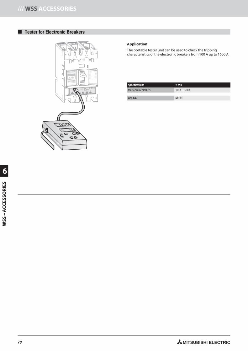
70 MITSUBISHI ELECTRIC
6
WSS
–A
CC
ESSO
RIE
S/// WSS ACCESSORIES
MITSUBISHI OFF
ON
NO-FUSE BREAKER
NF125-SGW
In A100Ir 63-100A
MODEL
POLE
Ui690V
Cat.A
PUSH TO TRIP
Uimp 8kV
3 P
IEC60947-2
JIS C 8201-2
Ue690VAC
525VAC
500VAC
440VAC
380/415VAC
230VAC
300VAC
EN60947-2
40°C
Icu/Ics
8/8kA
22/22kA
30/30kA
36/36kA
36/36kA
85/85kA
20/20kA
MITSUBISHI ELECTRIC
PAL70%50/60Hz
T
TsTL
IiIs
IrIp OVERMODEL
RE100 In 100A
Ii(X100A)
Ir(A) TL(S) IS(xIr) TS(S) Ip(xIr)
63 100 10012 22.5
10 .06.07 .10
.3 4
6
8 10
12
14
.1 .2
87
65480 3.53
60 80
T
POWERON
000
L 30
Tester for Electronic Breakers
Application
The portable tester unit can be used to check the trippingcharacteristics of the electronic breakers from 100 A up to 1600 A.
Specifications Y-250
for electronic breakers 100 A– 1600 A
Art. no. 68181
70neue Seiten_GB.prnLVS-Family - Technical SectionFreitag, 30. Januar 2009 14:23:50
Farbprofil: DeaktiviertKomposit Standardbildschirm
71MITSUBISHI ELECTRIC
WSS
–A
CC
ESSO
RIE
S
6
WSS ACCESSORIES ///
71neue Seiten_GB.prnLVS-Family - Technical SectionFreitag, 30. Januar 2009 14:23:54
Farbprofil: DeaktiviertKomposit Standardbildschirm
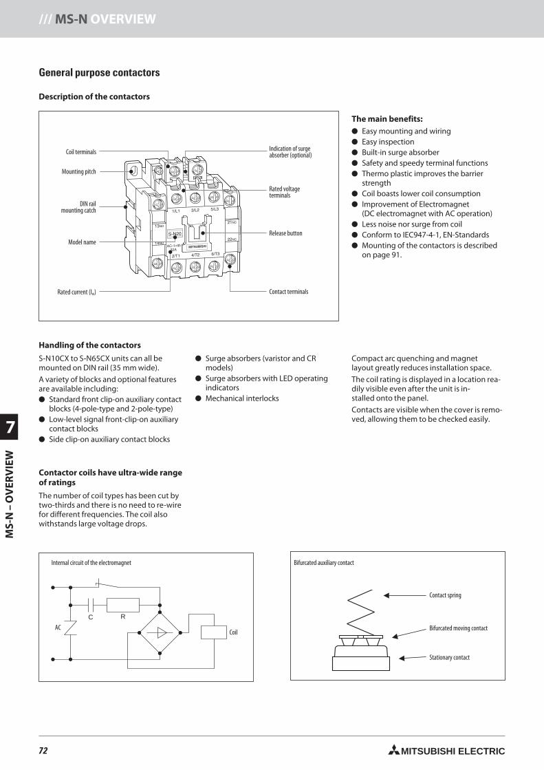
72 MITSUBISHI ELECTRIC
7
MS-
N–
OV
ERV
IEW
/// MS-N OVERVIEW
Coil
C R
General purpose contactors
Description of the contactors
Bifurcated moving contact
Contact spring
Stationary contact
Bifurcated auxiliary contactInternal circuit of the electromagnet
CoilAC
Contactor coils have ultra-wide rangeof ratings
The number of coil types has been cut bytwo-thirds and there is no need to re-wirefor different frequencies. The coil alsowithstands large voltage drops.
Handling of the contactors
S-N10CX to S-N65CX units can all bemounted on DIN rail (35 mm wide).
A variety of blocks and optional featuresare available including: Standard front clip-on auxiliary contact
blocks (4-pole-type and 2-pole-type) Low-level signal front-clip-on auxiliary
contact blocks Side clip-on auxiliary contact blocks
Surge absorbers (varistor and CRmodels)
Surge absorbers with LED operatingindicators
Mechanical interlocks
Compact arc quenching and magnetlayout greatly reduces installation space.
The coil rating is displayed in a location rea-dily visible even after the unit is in-stalled onto the panel.
Contacts are visible when the cover is remo-ved, allowing them to be checked easily.
The main benefits: Easy mounting and wiring Easy inspection Built-in surge absorber Safety and speedy terminal functions Thermo plastic improves the barrier
strength Coil boasts lower coil consumption Improvement of Electromagnet
(DC electromagnet with AC operation) Less noise nor surge from coil Conform to IEC947-4-1, EN-Standards Mounting of the contactors is described
on page 91.
DIN railmounting catch
Contact terminals
Coil terminals Indication of surgeabsorber (optional)
Model name
Rated voltageterminals
Mounting pitch
Rated current (Ith)
Release button
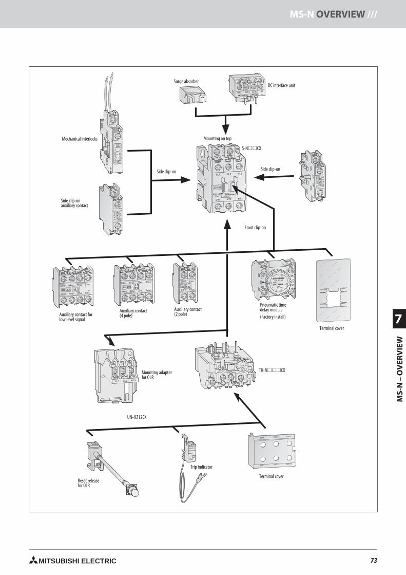
73MITSUBISHI ELECTRIC
MS-
N–
OV
ERV
IEW
7
MS-N OVERVIEW ///
54
54
Produktübersicht Leistungsschütze, Überstromrelais
Mechanical interlocks
Side clip-onauxiliary contact
Surge absorber
Mounting on top
DC interface unit
Auxiliary contact forlow level signal
Terminal cover
Mounting adapterfor OLR
Pneumatic timedelay module(Factory install)
Reset releasefor OLR
Auxiliary contact(4 pole)
Trip indicator
Auxiliary contact(2 pole)
Front clip-on
Side clip-on Side clip-on
Terminal cover
73neue Seiten_GB.prnLVS-Family - Technical SectionFreitag, 30. Januar 2009 14:24:19
Farbprofil: DeaktiviertKomposit Standardbildschirm
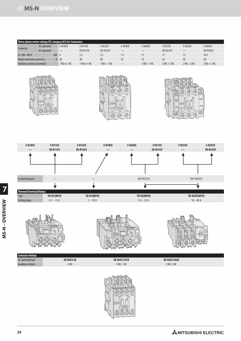
74 MITSUBISHI ELECTRIC
7
MS-
N–
OV
ERV
IEW
/// MS-N OVERVIEW
Three-phase motor ratings IEC category AC3 for Contactors
ContactorAC-operated S-N10CX S-N11CX S-N12CX S-N18CX S-N20CX S-N21CX S-N25CX S-N35CXDC-operated — SD-N11CX SD-N12CX — — SD-N21CX — SD-N35CX
AC 380–440 V kW 4 5.5 5.5 7.5 11 11 15 18.5Rated continuous current Ith A 20 20 20 25 32 32 50 60Auxiliary contacts (standard) 1 NO or 1 NC 1 NO or 1 NC 1 NO + 1 NC — 1 NO + 1 NC 2 NO + 2 NC 2 NO + 2 NC 2 NO + 2 NC
S-N10CX S-N11CX S-N12CX S-N18CX S-N20CX S-N21CX S-N25CX S-N35CX— SD-N11CX SD-N12CX — — SD-N21CX — SD-N35CX
Connecting parts — — UN-TH21CX UN-TH25CX
Thermal Overload RelaysType TH-N12KPCX TH-N18KPCX TH-N20KPCX TH-N20TAKPCXSetting range 0.1 – 13 A 1 – 18 A 0.2 – 22 A 18 – 40 A
Contactor RelaysAC-operated type SR-N4CX 4A SR-N4CX 3A1B SR-N4CX 2A2BAuxiliary contacts 4 NO 3 NO, 1 NC 2 NO, 2 NC
Produktübersicht Leistungsschütze und Relais
74neue Seiten_GB.prnLVS-Family - Technical SectionFreitag, 30. Januar 2009 14:24:50
Farbprofil: DeaktiviertKomposit Standardbildschirm
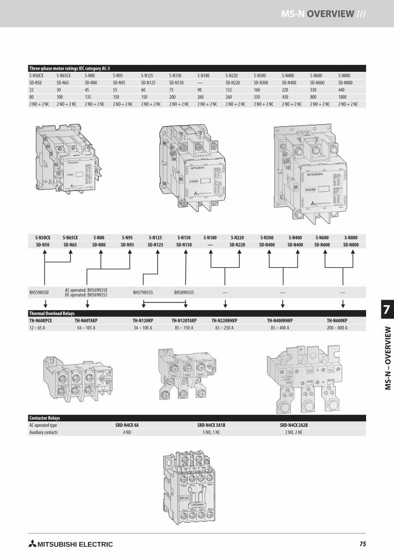
75MITSUBISHI ELECTRIC
MS-
N–
OV
ERV
IEW
7
MS-N OVERVIEW ///
Three-phase motor ratings IEC category AC-3S-N50CX S-N65CX S-N80 S-N95 S-N125 S-N150 S-N180 S-N220 S-N300 S-N400 S-N600 S-N800SD-N50 SD-N65 SD-N80 SD-N95 SD-N125 SD-N150 — SD-N220 SD-N300 SD-N400 SD-N600 SD-N80022 30 45 55 60 75 90 132 160 220 330 44080 100 135 150 150 200 260 260 350 450 800 10002 NO + 2 NC 2 NO + 2 NC 2 NO + 2 NC 2 NO + 2 NC 2 NO + 2 NC 2 NO + 2 NC 2 NO + 2 NC 2 NO + 2 NC 2 NO + 2 NC 2 NO + 2 NC 2 NO + 2 NC 2 NO + 2 NC
JEM 1038NK 98T405AC3 1 1-0V~ kW220 19440 37550 45
IEC60947-4-1DIN VDEBS EN AC-3V~ kW240 22440 45500 45690 45
BH762Y900H03MITSUBISHI ELECTRIC
S-N80
MITSUBISHI ELECTRIC
S-N50CX S-N65CX S-N80 S-N95 S-N125 S-N150 S-N180 S-N220 S-N300 S-N400 S-N600 S-N800SD-N50 SD-N65 SD-N80 SD-N95 SD-N125 SD-N150 — SD-N220 SD-N400 SD-N400 SD-N600 SD-N800
BH559N350 AC operated: BH569N350DC operated: BH569N352 BH579N355 BH589N355 — — —
Thermal Overload RelaysTH-N60KPCX TH-N60TAKP TH-N120KP TH-N120TAKP TH-N220RHKP TH-N400RHKP TH-N600KP12 – 65 A 54 – 105 A 34 – 100 A 85 – 150 A 65 – 250 A 85 – 400 A 200 – 800 A
Contactor RelaysAC operated type SRD-N4CX 4A SRD-N4CX 3A1B SRD-N4CX 2A2BAuxiliary contacts 4 NO 3 NO, 1 NC 2 NO, 2 NC
MITSUBISHI ELECTRIC
S-N150
JEM 1038NK 98T408AC3 1 1-0V~ kW220 37440 75550 90
IEC60947-4-1DIN VDEBS EN AC-3V~ kW240 45440 75500 90690 90
BH782Y900H03
75neue Seiten_GB.prnLVS-Family - Technical SectionFreitag, 30. Januar 2009 14:25:22
Farbprofil: DeaktiviertKomposit Standardbildschirm
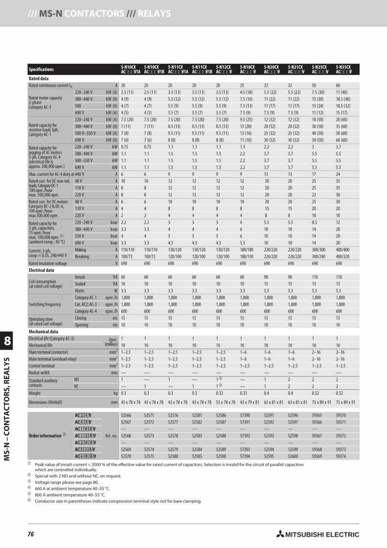
76 MITSUBISHI ELECTRIC
8
MS-
N–
CO
NTA
CTO
RS,
REA
LYS
/// MS-N CONTACTORS /// RELAYS
Specifications S-N10CXAC
S-N10CXACV1B
S-N11CXACV1A
S-N11CXACV1B
S-N12CXACV
S-N18CXACV
S-N20CXACV
S-N21CXACV
S-N25CXACV
S-N35CXACV
Rated dataRated continuous current Ith A 20 20 20 20 20 25 32 32 50 60
Rated motor capacity3-phaseCategory AC-3
220–240 V kW (A) 2.5 (11) 2.5 (11) 3.5 (13) 3.5 (13) 3.5 (13) 4.5 (18) 5.5 (22) 5.5 (22) 7.5 (30) 11 (40)380–440 V kW (A) 4 (9) 4 (9) 5.5 (12) 5.5 (12) 5.5 (12) 7.5 (16) 11 (22) 11 (22) 15 (30) 18.5 (40)500 kW (A) 4 (7) 4 (7) 5.5 (9) 5.5 (9) 5.5 (9) 7.5 (13) 11 (17) 11 (17) 15 (24) 18.5 (32)690 V kW (A) 4 (5) 4 (5) 5.5 (7) 5.5 (7) 5.5 (7) 7.5 (9) 7.5 (9) 7.5 (9) 11 (12) 15 (17)
Rated capacity forresistive loads 3ph,Category AC-1
220–240 V kW (A) 7.5 (20) 7.5 (20) 7.5 (20) 7.5 (20) 7.5 (20) 9.5 (25) 12 (32) 12 (32) 18 (50) 20 (60)380–440 V kW (A) 7 (11) 7 (11) 8.5 (13) 8.5 (13) 8.5 (13) 13 (20) 20 (32) 20 (32) 30 (50) 35 (60)500 V–550 V kW (A) 7 (8) 7 (8) 9.5 (11) 9.5 (11) 9.5 (11) 13 (16) 25 (32) 25 (32) 40 (50) 50 (60)690 V kW (A) 7 (6) 7 (6) 8 (8) 8 (8) 8 (8) 11 (10) 30 (32) 30 (32) 50 (50) 60 (60)
Rated capacity forjogging of AC motors3-ph, Category AC-4(electrical life isapprox. 200,000 oper.)
220–240 V kW 0.75 0.75 1.1 1.1 1.1 1.5 2.2 2.2 3 3.7380–440 V kW 1.1 1.1 1.5 1.5 1.5 2.2 3.7 3.7 5.5 5.5500–550 V kW 1.1 1.1 1.5 1.5 1.5 2.2 3.7 3.7 5.5 5.5690 V kW 1.1 1.1 1.5 1.5 1.5 2.2 3.7 3.7 5.5 5.5
Max. current for AC-4 duty at 440 V A 6 6 9 9 9 9 13 13 17 24Rated curr. for DC non-ind.loads, Category DC-1100 oper./hourmax. 500,000 oper.
48 V A 10 10 12 12 12 12 20 20 25 35110 V A 8 8 12 12 12 12 20 20 25 35220 V A 8 8 12 12 12 12 20 20 22 30
Rated curr. for DC motorsCategory DC-2 & DC-4,100 oper./hourmax.500,000 oper.
48 V A 6 6 10 10 10 10 20 20 25 30110 V A 4 4 8 8 8 8 15 15 20 20220 V A 2 2 4 4 4 4 8 8 10 10
Rated capacity for3-ph, capacitors,15 oper./hourmax. 100,000 oper.
(ambient temp.: 40 °C)
220–240 V kvar 2.2 2.2 3 3 3 4 5.5 5.5 8.5 12380–440 V kvar 3.3 3.3 4 4 4 6 10 10 14 20550 V kvar 4 4 5 5 5 6 10 10 14 20690 V kvar 3.3 3.3 4.5 4.5 4.5 5.5 10 10 14 20
Current; 3-ph,cosϕ = 0.35, 240/440 V
Making A 110/110 110/110 130/120 130/120 130/120 180/180 220/220 220/220 300/300 400/400Breaking A 100/72 100/72 120/100 120/100 120/100 180/130 220/220 220/220 300/240 400/320
Rated insulation voltage V 690 690 690 690 690 690 690 690 690 690Electrical data
Coil consumption(at rated coil voltage)
Inrush VA 60 60 60 60 60 60 90 90 110 110Sealed VA 10 10 10 10 10 10 15 15 13 13Watts W 3.5 3.5 3.5 3.5 3.5 3.5 5.3 5.3 5.3 5.3
Switching frequencyCategory AC-1 oper./h 1,800 1,800 1,800 1,800 1,800 1,800 1,800 1,800 1,800 1,800Cat. AC2; AC-3 oper./h 1,800 1,800 1,800 1,800 1,800 1,800 1,800 1,800 1,800 1,800Category AC-4 oper./h 600 600 600 600 600 600 600 600 600 600
Operating time(at rated coil voltage)
Closing ms 15 15 15 15 15 15 15 15 15 15Opening ms 10 10 10 10 10 10 10 10 10 10
Mechanical dataElectrical life (Category AC-3) Oper.
(million)1 1 1 1 1 1 1 1 1 1
Mechanical life 10 10 10 10 10 10 10 10 10 10Main terminal (contactor) mm2 1–2.5 1–2.5 1–2.5 1–2.5 1–2.5 1–6 1–6 1–6 2–16 2–16Main terminal (overload relay) mm2 1–2.5 1–2.5 1–2.5 1–2.5 1–2.5 1–6 1–6 1–6 2–16 2–16Control terminal mm2 1–2.5 1–2.5 1–2.5 1–2.5 1–2.5 1–2.5 1–2.5 1–2.5 1–2.5 1–2.5Busbar width mm — — — — — — — — — —
Standard auxiliarycontacts
NO 1 — 1 — 1 — 1 2 2 2NC — 1 — 1 1 — 1 2 2 2
Weight kg 0.3 0.3 0.3 0.3 0.32 0.33 0.4 0.4 0.52 0.52
Dimensions (WxHxD) mm 43 x 78 x 78 43 x 78 x 78 43 x 78 x 78 43 x 78 x 78 53 x 78 x 78 43 x 79 x 81 63 x 81 x 81 63 x 81 x 81 75 x 89 x 91 75 x 89 x 91
Order information
AC24V
Art. no.
52566 52571 52576 52581 52586 57390 52591 52596 59365 59370AC48V 52567 52572 52577 52582 52587 57391 52592 52597 59366 59371AC100V — — — — — — — — — —AC120V 52568 52573 52578 52583 52588 57392 52593 52598 59367 59372AC200V — — — — — — — — — —AC230V 52569 52574 52579 52584 52589 57393 52594 52599 59368 59373AC400V 52570 52575 52580 52585 52590 57394 52595 52600 59369 59374
Peak value of inrush current < 2000 % of the effective value for rated current of capacitors. Selection is invalid for the circuit of parallel capacitorswhich are controlled individually.
Special with 2 NO and without NC; on request. Voltage range please see page 80. 660 A at ambient temperature 40–55 °C. 800 A ambient temperature 40–55 °C. Conductor size in parentheses indicate compression terminal style not for bare clamping.
76neue Seiten_GB.prnLVS-Family - Technical SectionFreitag, 30. Januar 2009 14:25:30
Farbprofil: DeaktiviertKomposit Standardbildschirm
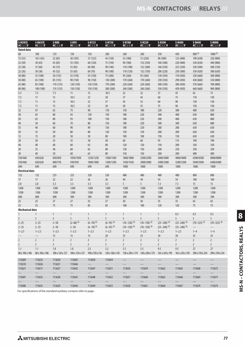
77MITSUBISHI ELECTRIC
MS-
N–
CO
NTA
CTO
RS,
REA
LYS
8
MS-N CONTACTORS /// RELAYS ///
S-N50CXACV
S-N65CXACV
S-N80ACV
S-N95ACV
S-N125ACV
S-N150ACV
S-N180ACV
S-N220ACV
S-N300ACV
S-N400ACV
S-N600ACV
S-N800ACV
Rated data80 100 135 150 150 200 260 260 350 450 800 1000
15 (55) 18.5 (65) 22 (85) 30 (105) 37 (125) 45 (150) 55 (180) 75 (250) 90 (300) 125 (400) 190 (630) 220 (800)22 (50) 30 (65) 45 (85) 55 (105) 60 (120) 75 (150) 90 (180) 132 (250) 160 (300) 220 (400) 330 (630) 440 (800)25 (38) 37 (60) 45 (75) 55 (85) 60 (90) 90 (140) 110 (180) 132 (200) 160 (250) 225 (350) 330 (500) 500 (720)22 (26) 30 (38) 45 (52) 55 (65) 60 (70) 90 (100) 110 (120) 132 (150) 200 (220) 250 (300) 330 (420) 500 (630)30 (80) 35 (100) 50 (135) 55 (150) 55 (150) 75 (200) 95 (260) 95 (260) 130 (350) 170 (450) 250 (660) 300 (800)50 (80) 65 (100) 85 (135) 90 (150) 90 (150) 130 (200) 170 (260) 170 (260) 230 (350) 290 (450) 430 (660) 530 (800)65 (80) 85 (100) 110 (135) 120 (150) 120 (150) 170 (200) 220 (260) 220 (260) 300 (350) 380 (450) 570 (660) 700 (800)80 (80) 100 (100) 135 (135) 150 (150) 150 (150) 200 (200) 260 (260) 260 (260) 350 (350) 450 (450) 660 (660) 900 (800)5.5 7.5 7.5 11 15 18.5 22 22 37 45 65 757.5 11 15 18.5 22 30 37 45 60 75 110 1307.5 11 15 18.5 22 37 45 55 60 90 130 1307.5 11 15 18.5 22 30 50 55 75 90 130 15032 47 62 75 90 110 150 180 220 300 400 63050 65 80 93 120 150 180 220 300 400 630 80050 65 80 93 100 150 180 220 300 400 630 80040 50 60 70 80 150 180 220 300 300 630 80035 40 60 90 90 130 180 220 280 280 630 63030 35 50 80 80 120 150 150 200 200 630 63012 15 20 50 50 80 100 100 150 150 630 63020 20 35 35 38 50 60 60 95 115 190 19040 40 60 60 65 80 120 120 150 200 350 35030 35 48 60 65 80 150 150 200 250 350 35030 40 50 60 65 80 150 150 200 200 400 400550/460 650/620 850/850 1050/1050 1250/1250 1500/1500 1800/1800 2500/2500 3000/3000 4000/4000 6500/6500 8000/8000550/460 650/620 800/750 930/930 1000/1000 1200/1200 1450/1450 2000/2000 2400/2400 3200/3200 5040/5040 6400/6400690 690 690 690 690 690 1000 1000 1000 1000 1000 1000Electrical data132 132 225 225 320 320 480 480 480 480 800 80017 17 22 22 26 26 44 44 54 54 100 1002.8 2.8 3.3 3.3 3.5 3.5 5 5 7.3 7.3 15 151200 1200 1200 1200 1200 1200 1200 1200 1200 1200 1200 12001200 1200 1200 1200 1200 1200 1200 1200 1200 1200 1200 1200600 600 600 300 300 300 300 300 300 300 300 30025 25 27 27 25 27 30 30 35 35 65 6553 53 75 75 85 85 100 100 120 120 75 75Mechanical data1 1 1 1 1 1 1 1 1 0.5 0.5 0.55 5 5 5 5 5 5 5 5 5 5 52–25 2–25 2–50 (2–60) (6–70) (6–95) (10–120) (10–150) (25–240) (25–240) (70–325) (70–325)
2–25 2–25 2–50 2–50 (6–70) (6–95) (10–120) (10–150) (25–240) (25–240) — —1–2.5 1–2.5 1–2.5 1–2.5 1–2.5 1–2.5 1–2.5 1–2.5 1–2.5 1–2.5 1–4 1–4— — 15 15 15 20 25 25 30 30 35 352 2 2 2 2 2 2 2 2 2 2 22 2 2 2 2 2 2 2 2 2 2 21.1 1.1 1.8 1.8 2.5 3.2 5.5 5.5 9.5 9.5 27 2788 x 106 x 106 88 x 106 x 106 100 x 124 x 127 100 x 124 x 127 100 x 150 x 136 120 x 160 x 145 138 x 204 x 174 138 x 204 x 174 163 x 243 x 195 163 x 243 x 195 290 x 310 x 234 290 x 310x 234
113609 113633 113630 113645 113650 113654 — — — — — —113610 113636 113631 113646 — — — — — — — —113621 113611 113627 113642 113647 113651 113656 113659 113662 113665 113668 113672— — — — — — — — — — — —113607 113632 113628 113643 113648 113652 113657 113660 113663 113666 113669 113673— — — — — — — — — — — —113608 113635 113629 113644 113649 113653 113658 113661 113664 113667 113670 113674
For specifications of the standard auxiliary contacts refer to page .
77neue Seiten_GB.prnLVS-Family - Technical SectionFreitag, 30. Januar 2009 14:25:34
Farbprofil: DeaktiviertKomposit Standardbildschirm
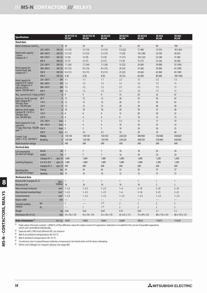
78 MITSUBISHI ELECTRIC
8
MS-
N–
CO
NTA
CTO
RS,
REA
LYS
/// MS-N CONTACTORS /// RELAYS
Specifications SD-N11CX 1ADC24V
SD-N11CX 1BDC24V
SD-N12CXDC24V
SD-N21CXDC24V
SD-N35CXDC24V
SD-N50DC24V
SD-N65DC24V
Rated dataRated continuous current Ith A 20 20 20 32 60 80 100
Rated motor capacity3-phaseCategory AC-3
220–240 V kW (A) 3.5 (13) 3.5 (13) 3.5 (13) 5.5 (22) 11 (40) 15 (55) 18.5 (65)380–440 V kW (A) 5.5 (12) 5.5 (12) 5.5 (12) 11 (22) 18.5 (40) 22 (50) 30 (65)500–550 V kW (A) 5.5 (9) 5.5 (9) 5.5 (9) 11 (17) 18.5 (32) 25 (38) 37 (60)690 V kW (A) 5.5 (7) 5.5 (7) 5.5 (7) 7.5 (9) 15 (17) 22 (26) 30 (38)
Rated capacity forresistive loads 3ph,category AC-1
220–240 V kW (A) 7.5 (20) 7.5 (20) 7.5 (20) 12 (32) 20 (60) 30 (80) 35 (100)380–440 V kW (A) 8.5 (13) 8.5 (13) 8.5 (13) 20 (32) 35 (60) 50 (80) 65 (100)500 V kW (A) 9.5 (11) 9.5 (11) 9.5 (11) 25 (32) 50 (60) 65 (80) 85 (100)690 V kW (A) 8 (8) 8 (8) 8 (8) 30 (32) 60 (60) 80 (80) 100 (100)
Rated capacity forjogging of AC motors3-ph, category AC-4(electrical life isapprox. 200,000 oper.)
220–240 V kW 1.1 1.1 1.1 2.2 3.7 5.5 7.5380–440 V kW 1.5 1.5 1.5 3.7 5.5 7.5 11500–550 V kW 1.5 1.5 1.5 3.7 5.5 7.5 11690 V kW 1.5 1.5 1.5 3.7 5.5 7.5 11
Max. current for AC-4 duty at 440 V A 9 9 9 13 24 32 47Raed curr. for DC non-ind.loads, Category DC-1100 oper./hourmax. 500,000 oper.
48 V A 12 12 12 20 35 50 65110 V A 12 12 12 20 35 50 65220 V A 12 12 12 20 30 40 50
Rated curr. for DC motorsCategory DC-2 & DC-4,100 oper./hourmax. 500,000 oper.
48 V A 10 10 10 20 30 35 40110 V A 8 8 8 15 20 30 35220 V A 4 4 4 8 10 12 15
Rated capacity for 3-ph,capacitors,15 oper./hour max. 100,000oper.
220–240 V kvar 3 3 3 5.5 12 17 19380–440 V kvar 4 4 4 10 20 25 32550 V kvar 5 5 5 10 20 30 35690 V kvar 4.5 4.5 4.5 10 20 30 40
Current; 3-ph,cosΘ = 0.35; 240/440 V
Making A 130/120 130/120 130/120 220/220 400/400 550/460 650/620Breaking A 120/100 120/100 120/100 220/220 400/320 550/460 650/620
Rated insulation voltage V 690 690 690 690 690 690 690Electrical data
Coil consumption(at rated coil voltage)
Inrush VA 7 7 7 16 18 24 24Sealed VA 7 7 7 16 18 24 24
Switching frequencyCategory AC-1 oper./h 1,800 1,800 1,800 1,800 1,800 1,200 1,200Cat. AC2; AC3 oper./h 1,800 1,800 1,800 1,800 1,800 1,200 1,200Category AC-4 oper./h 600 600 600 600 600 600 600
Operating time(at rated coil voltage)
Closing ms 45 45 45 33 50 57 57Opening ms 10 10 10 12 13 15 15
Mechanical dataElectrical life (Category AC-3) Oper.
(million)1 1 1 1 1 1 1
Mechanical life 10 10 10 10 10 5 5Main terminal (contactor) mm2 1–2.5 1–2.5 1–2.5 1–6 2–16 2–25 2–25Main terminal (overload relay) mm2 1–2.5 1–2.5 1–2.5 1–6 2–16 2–25 2–25Control terminal mm2 1–2.5 1–2.5 1–2.5 1–2.5 1–2.5 1–2.5 1–2.5Busbar width mm — — — — — — —
Standard auxiliarycontacts
NO 1 — 1 2 2 2 2NC — 1 1 2 2 2 2
Weight kg 0.62 0.62 0.64 0.72 0.85 2.1 2.1Dimensions (W x H x D) mm 43 x 78 x 110 43 x 78 x 110 53 x 78 x 110 63 x 81 x 113 75 x 89 x 123 88 x 110 x 133 88 x 110 x 133
Order information Art. no. 52601 52602 52603 52604 58533 113675 113678 Peak value of inrush current < 2000 % of the effective value for rated current of capacitors. Selection is invalid for the circuit of parallel capacitors
which are controlled individually. Special with 2 NO and without NC; on request 660 A at ambient temperature 40–55 °C. 800 A ambient temperature 40–55 °C. Conductor size in parentheses indicate compression terminal style not for bare clamping. Other coil voltages on request (please see page 80).
78neue Seiten_GB.prnLVS-Family - Technical SectionFreitag, 30. Januar 2009 14:25:39
Farbprofil: DeaktiviertKomposit Standardbildschirm
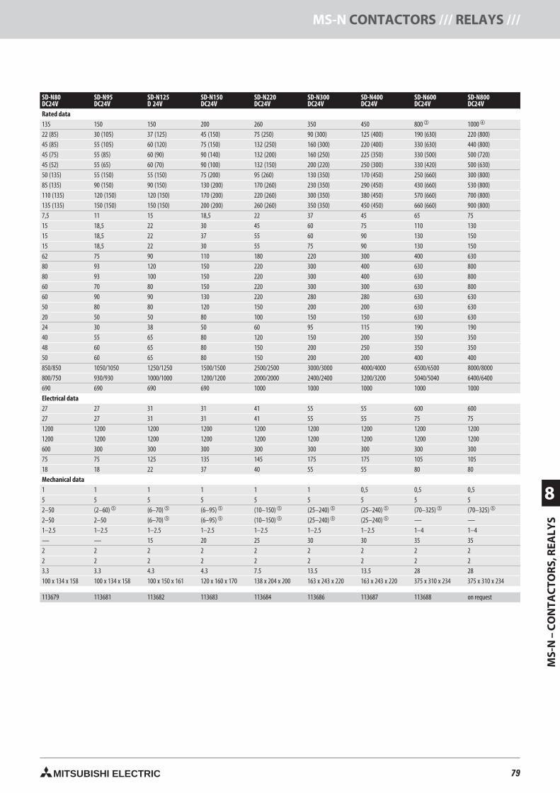
79MITSUBISHI ELECTRIC
MS-
N–
CO
NTA
CTO
RS,
REA
LYS
8
MS-N CONTACTORS /// RELAYS ///
SD-N80DC24V
SD-N95DC24V
SD-N125D 24V
SD-N150DC24V
SD-N220DC24V
SD-N300DC24V
SD-N400DC24V
SD-N600DC24V
SD-N800DC24V
Rated data135 150 150 200 260 350 450 800 1000
22 (85) 30 (105) 37 (125) 45 (150) 75 (250) 90 (300) 125 (400) 190 (630) 220 (800)45 (85) 55 (105) 60 (120) 75 (150) 132 (250) 160 (300) 220 (400) 330 (630) 440 (800)45 (75) 55 (85) 60 (90) 90 (140) 132 (200) 160 (250) 225 (350) 330 (500) 500 (720)45 (52) 55 (65) 60 (70) 90 (100) 132 (150) 200 (220) 250 (300) 330 (420) 500 (630)50 (135) 55 (150) 55 (150) 75 (200) 95 (260) 130 (350) 170 (450) 250 (660) 300 (800)85 (135) 90 (150) 90 (150) 130 (200) 170 (260) 230 (350) 290 (450) 430 (660) 530 (800)110 (135) 120 (150) 120 (150) 170 (200) 220 (260) 300 (350) 380 (450) 570 (660) 700 (800)135 (135) 150 (150) 150 (150) 200 (200) 260 (260) 350 (350) 450 (450) 660 (660) 900 (800)7,5 11 15 18,5 22 37 45 65 7515 18,5 22 30 45 60 75 110 13015 18,5 22 37 55 60 90 130 15015 18,5 22 30 55 75 90 130 15062 75 90 110 180 220 300 400 63080 93 120 150 220 300 400 630 80080 93 100 150 220 300 400 630 80060 70 80 150 220 300 300 630 80060 90 90 130 220 280 280 630 63050 80 80 120 150 200 200 630 63020 50 50 80 100 150 150 630 63024 30 38 50 60 95 115 190 19040 55 65 80 120 150 200 350 35048 60 65 80 150 200 250 350 35050 60 65 80 150 200 200 400 400850/850 1050/1050 1250/1250 1500/1500 2500/2500 3000/3000 4000/4000 6500/6500 8000/8000800/750 930/930 1000/1000 1200/1200 2000/2000 2400/2400 3200/3200 5040/5040 6400/6400690 690 690 690 1000 1000 1000 1000 1000Electrical data27 27 31 31 41 55 55 600 60027 27 31 31 41 55 55 75 751200 1200 1200 1200 1200 1200 1200 1200 12001200 1200 1200 1200 1200 1200 1200 1200 1200600 300 300 300 300 300 300 300 30075 75 125 135 145 175 175 105 10518 18 22 37 40 55 55 80 80Mechanical data1 1 1 1 1 1 0,5 0,5 0,55 5 5 5 5 5 5 5 52–50 (2–60) (6–70) (6–95) (10–150) (25–240) (25–240) (70–325) (70–325)
2–50 2–50 (6–70) (6–95) (10–150) (25–240) (25–240) — —1–2.5 1–2.5 1–2.5 1–2.5 1–2.5 1–2.5 1–2.5 1–4 1–4— — 15 20 25 30 30 35 352 2 2 2 2 2 2 2 22 2 2 2 2 2 2 2 23.3 3.3 4.3 4.3 7.5 13.5 13.5 28 28100 x 134 x 158 100 x 134 x 158 100 x 150 x 161 120 x 160 x 170 138 x 204 x 200 163 x 243 x 220 163 x 243 x 220 375 x 310 x 234 375 x 310 x 234
113679 113681 113682 113683 113684 113686 113687 113688 on request
79neue Seiten_GB.prnLVS-Family - Technical SectionFreitag, 30. Januar 2009 14:25:43
Farbprofil: DeaktiviertKomposit Standardbildschirm
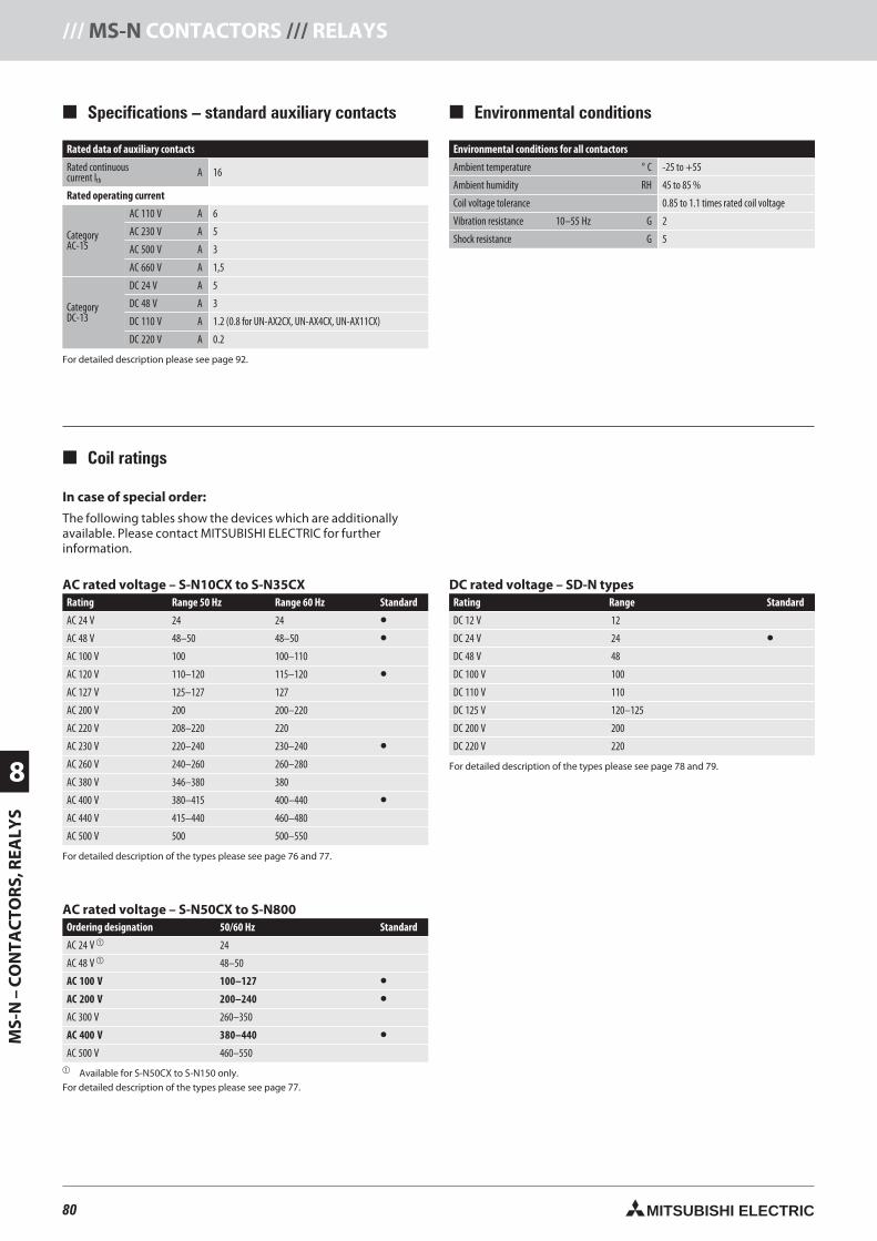
80 MITSUBISHI ELECTRIC
8
MS-
N–
CO
NTA
CTO
RS,
REA
LYS
/// MS-N CONTACTORS /// RELAYS
Markierung
In case of special order:
The following tables show the devices which are additionallyavailable. Please contact MITSUBISHI ELECTRIC for furtherinformation.
Rated data of auxiliary contacts
Rated continuouscurrent Ith
A 16
Rated operating current
CategoryAC-15
AC 110 V A 6
AC 230 V A 5
AC 500 V A 3
AC 660 V A 1,5
CategoryDC-13
DC 24 V A 5
DC 48 V A 3
DC 110 V A 1.2 (0.8 for UN-AX2CX, UN-AX4CX, UN-AX11CX)
DC 220 V A 0.2
For detailed description please see page 92.
Specifications – standard auxiliary contacts Environmental conditions
Coil ratings
Environmental conditions for all contactors
Ambient temperature ° C -25 to +55
Ambient humidity RH 45 to 85 %
Coil voltage tolerance 0.85 to 1.1 times rated coil voltage
Vibration resistance 10–55 Hz G 2
Shock resistance G 5
AC rated voltage – S-N50CX to S-N800Ordering designation 50/60 Hz Standard
AC 24 V 24
AC 48 V 48–50
AC 100 V 100–127 •AC 200 V 200–240 •AC 300 V 260–350
AC 400 V 380–440 •AC 500 V 460–550
Available for S-N50CX to S-N150 only.For detailed description of the types please see page 77.
AC rated voltage – S-N10CX to S-N35CXRating Range 50 Hz Range 60 Hz Standard
AC 24 V 24 24 •AC 48 V 48–50 48–50 •AC 100 V 100 100–110
AC 120 V 110–120 115–120 •AC 127 V 125–127 127
AC 200 V 200 200–220
AC 220 V 208–220 220
AC 230 V 220–240 230–240 •AC 260 V 240–260 260–280
AC 380 V 346–380 380
AC 400 V 380–415 400–440 •AC 440 V 415–440 460–480
AC 500 V 500 500–550
For detailed description of the types please see page 76 and 77.
DC rated voltage – SD-N typesRating Range Standard
DC 12 V 12
DC 24 V 24 •DC 48 V 48
DC 100 V 100
DC 110 V 110
DC 125 V 120–125
DC 200 V 200
DC 220 V 220
For detailed description of the types please see page 78 and 79.
80neue Seiten_GB.prnLVS-Family - Technical SectionFreitag, 30. Januar 2009 14:25:50
Farbprofil: DeaktiviertKomposit Standardbildschirm
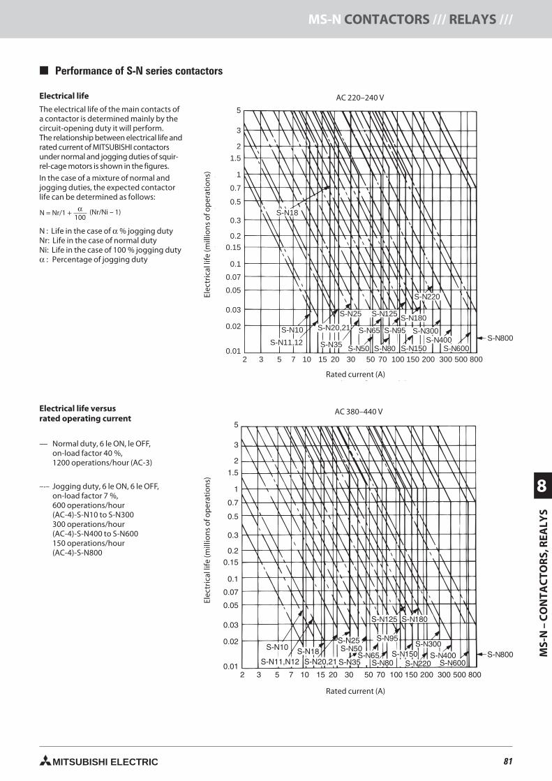
81MITSUBISHI ELECTRIC
MS-
N–
CO
NTA
CTO
RS,
REA
LYS
8
MS-N CONTACTORS /// RELAYS ///
Performance of S-N series contactors
Electrical life
The electrical life of the main contacts ofa contactor is determined mainly by thecircuit-opening duty it will perform.The relationship between electrical life andrated current of MITSUBISHI contactorsunder normal and jogging duties of squir-rel-cage motors is shown in the figures.
In the case of a mixture of normal andjogging duties, the expected contactorlife can be determined as follows:
N : Life in the case of α % jogging dutyNr: Life in the case of normal dutyNi: Life in the case of 100 % jogging dutyα : Percentage of jogging duty
Electrical life versusrated operating current
— Normal duty, 6 le ON, le OFF,on-load factor 40 %,1200 operations/hour (AC-3)
–.– Jogging duty, 6 le ON, 6 le OFF,on-load factor 7 %,600 operations/hour(AC-4)-S-N10 to S-N300300 operations/hour(AC-4)-S-N400 to S-N600150 operations/hour(AC-4)-S-N800
AC 220–240 V
Rated operating current (A)
Ele
ctric
allif
e(m
illio
nof
oper
atio
ns)
5
3
2
1.5
1
0.7
0.5
0.3
0.2
0.15
0.1
0.07
0.05
0.03
0.02
0.012 3 5 7 10 15 20 30 50 70 100 150 200 300 500 800
S-N800S-N600
S-N400S-N300
S-N150S-N50 S-N80
S-N95
S-N125S-N25
S-N20,21
S-N11,12
S-N10
S-N18
S-N35
S-N65
S-N180
S-N220
NNNN
N
N
NN
N
NN
N
N = Nr/1 + (Nr/Ni – 1)α100
AC 380–440 V
AC 220–240 V
Rated current (A)
Elec
tric
allif
e(m
illio
nsof
oper
atio
ns)
Rated current (A)
Elec
tric
allif
e(m
illio
nsof
oper
atio
ns)
81neue Seiten_GB.prnLVS-Family - Technical SectionFreitag, 30. Januar 2009 14:26:32
Farbprofil: DeaktiviertKomposit Standardbildschirm
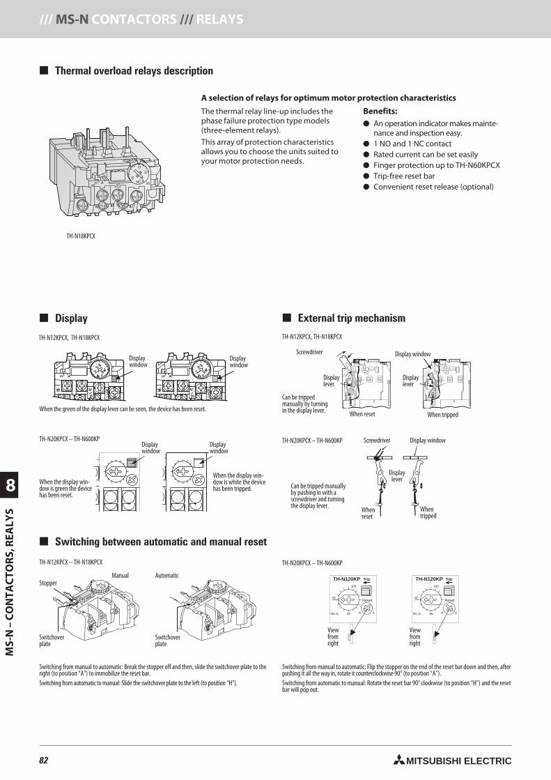
82 MITSUBISHI ELECTRIC
8
MS-
N–
CO
NTA
CTO
RS,
REA
LYS
/// MS-N CONTACTORS /// RELAYS
Thermal overload relays description
A selection of relays for optimum motor protection characteristics
The thermal relay line-up includes thephase failure protection type models(three-element relays).
This array of protection characteristicsallows you to choose the units suited toyour motor protection needs.
Benefits: An operation indicator makes mainte-
nance and inspection easy. 1 NO and 1 NC contact Rated current can be set easily Finger protection up to TH-N60KPCX Trip-free reset bar Convenient reset release (optional)
Display
Switching between automatic and manual reset
TH-N120KP TH-N120KP
Reset Reset
RC.A. RC.A.
Trip Trip
100 100
82 82
65 65H HA A
TH-N20KPCX – TH-N600KPTH-N12KPCX – TH-N18KPCX
Switchoverplate
StopperManual
Switchoverplate
TH-N12KPCX, TH-N18KPCX
Can be trippedmanually by turningin the display lever.
Display window
Displaylever
Displaylever
Screwdriver
When reset When tripped
Displaywindow
TH-N12KPCX, TH-N18KPCX
When the green of the display lever can be seen, the device has been reset.
External trip mechanism
TH-N20KPCX – TH-N600KP
Can be tripped manuallyby pushing in with ascrewdriver and turningthe display lever.
Displaywindow
TH-N20KPCX – TH-N600KP
When the display win-dow is green the devicehas been reset.
When the display win-dow is white the devicehas been tripped.
Switching from manual to automatic: Break the stopper off and then, slide the switchover plate to theright (to position “A”) to immobilize the reset bar.Switching from automatic to manual: Slide the switchover plate to the left (to position “H”).
Automatic
Switching from manual to automatic: Flip the stopper on the end of the reset bar down and then, afterpushing it all the way in, rotate it counterclockwise 90° (to position “A”).Switching from automatic to manual: Rotate the reset bar 90° clockwise (to position “H”) and the resetbar will pop out.
TH-N18KPCX
Displaywindow
Displaywindow
Displaywindow
Displaywindow
Viewfromright
Viewfromright
Display window
Whentripped
Whenreset
Screwdriver
Displaylever
82neue Seiten_GB.prnLVS-Family - Technical SectionFreitag, 30. Januar 2009 14:26:58
Farbprofil: DeaktiviertKomposit Standardbildschirm
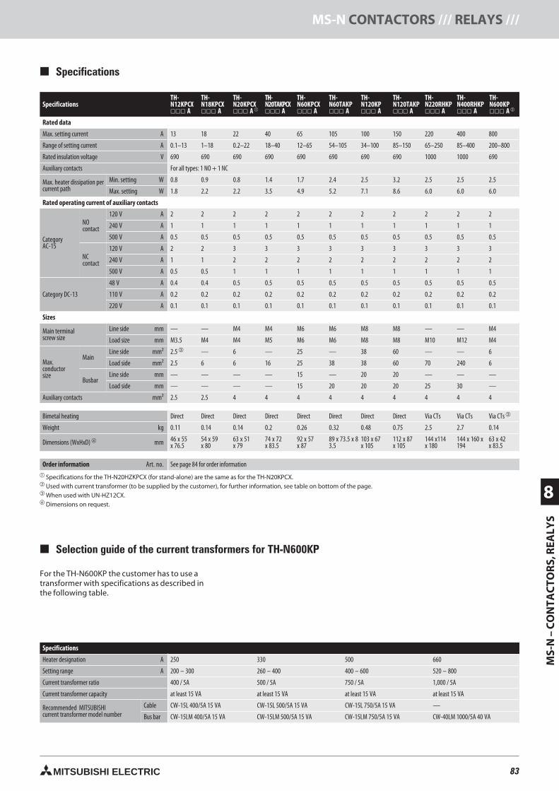
83MITSUBISHI ELECTRIC
MS-
N–
CO
NTA
CTO
RS,
REA
LYS
8
MS-N CONTACTORS /// RELAYS ///
Selection guide of the current transformers for TH-N600KP
For the TH-N600KP the customer has to use atransformer with specifications as described inthe following table.
Specifications
Heater designation A 250 330 500 660
Setting range A 200 – 300 260 – 400 400 – 600 520 – 800
Current transformer ratio 400 / 5A 500 / 5A 750 / 5A 1,000 / 5A
Current transformer capacity at least 15 VA at least 15 VA at least 15 VA at least 15 VA
Recommended MITSUBISHIcurrent transformer model number
Cable CW-15L 400/5A 15 VA CW-15L 500/5A 15 VA CW-15L 750/5A 15 VA —
Bus bar CW-15LM 400/5A 15 VA CW-15LM 500/5A 15 VA CW-15LM 750/5A 15 VA CW-40LM 1000/5A 40 VA
SpecificationsTH-N12KPCX A
TH-N18KPCX A
TH-N20KPCX A
TH-N20TAKPCX A
TH-N60KPCX A
TH-N60TAKP A
TH-N120KP A
TH-N120TAKP A
TH-N220RHKP A
TH-N400RHKP A
TH-N600KP A
Rated data
Max. setting current A 13 18 22 40 65 105 100 150 220 400 800
Range of setting current A 0.1–13 1–18 0.2–22 18–40 12–65 54–105 34–100 85–150 65–250 85–400 200–800
Rated insulation voltage V 690 690 690 690 690 690 690 690 1000 1000 690
Auxiliary contacts For all types: 1 NO + 1 NC
Max. heater dissipation percurrent path
Min. setting W 0.8 0.9 0.8 1.4 1.7 2.4 2.5 3.2 2.5 2.5 2.5
Max. setting W 1.8 2.2 2.2 3.5 4.9 5.2 7.1 8.6 6.0 6.0 6.0
Rated operating current of auxiliary contacts
CategoryAC-15
NOcontact
120 V A 2 2 2 2 2 2 2 2 2 2 2
240 V A 1 1 1 1 1 1 1 1 1 1 1
500 V A 0.5 0.5 0.5 0.5 0.5 0.5 0.5 0.5 0.5 0.5 0.5
NCcontact
120 V A 2 2 3 3 3 3 3 3 3 3 3
240 V A 1 1 2 2 2 2 2 2 2 2 2
500 V A 0.5 0.5 1 1 1 1 1 1 1 1 1
Category DC-13
48 V A 0.4 0.4 0.5 0.5 0.5 0.5 0.5 0.5 0.5 0.5 0.5
110 V A 0.2 0.2 0.2 0.2 0.2 0.2 0.2 0.2 0.2 0.2 0.2
220 V A 0.1 0.1 0.1 0.1 0.1 0.1 0.1 0.1 0.1 0.1 0.1
Sizes
Main terminalscrew size
Line side mm — — M4 M4 M6 M6 M8 M8 — — M4
Load size mm M3.5 M4 M4 M5 M6 M6 M8 M8 M10 M12 M4
Max.conductorsize
MainLine side mm² 2.5 — 6 — 25 — 38 60 — — 6
Load side mm² 2.5 6 6 16 25 38 38 60 70 240 6
BusbarLine side mm — — — — 15 — 20 20 — — —
Load side mm — — — — 15 20 20 20 25 30 —
Auxiliary contacts mm² 2.5 2.5 4 4 4 4 4 4 4 4 4
Bimetal heating Direct Direct Direct Direct Direct Direct Direct Direct Via CTs Via CTs Via CTs
Weight kg 0.11 0.14 0.14 0.2 0.26 0.32 0.48 0.75 2.5 2.7 0.14
Dimensions (WxHxD) mm 46 x 55x 76.5
54 x 59x 80
63 x 51x 79
74 x 72x 83.5
92 x 57x 87
89 x 73.5 x 83.5
103 x 67x 105
112 x 87x 105
144 x114x 180
144 x 160 x194
63 x 42x 83.5
Order information Art. no. See page 84 for order information Specifications for the are the same as for the TH-N20KPCX. Used with current transformer (to be supplied by the customer), for further information, see table on bottom of the page. When used with UN-HZ12CX. Dimensions on request.
Specifications
83neue Seiten_GB.prnLVS-Family - Technical SectionFreitag, 30. Januar 2009 14:27:04
Farbprofil: DeaktiviertKomposit Standardbildschirm
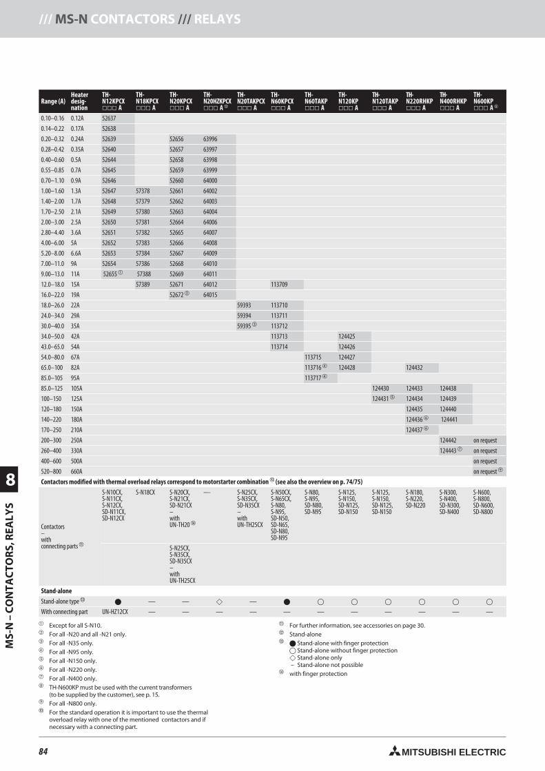
84 MITSUBISHI ELECTRIC
8
MS-
N–
CO
NTA
CTO
RS,
REA
LYS
/// MS-N CONTACTORS /// RELAYS
Range (A)Heaterdesig-nation
TH-N12KPCX A
TH-N18KPCX A
TH-N20KPCX A
TH-N20HZKPCX A
TH-N20TAKPCX A
TH-N60KPCX A
TH-N60TAKP A
TH-N120KP A
TH-N120TAKP A
TH-N220RHKP A
TH-N400RHKP A
TH-N600KP A
0.10–0.16 0.12A 52637
0.14–0.22 0.17A 52638
0.20–0.32 0.24A 52639 52656 63996
0.28–0.42 0.35A 52640 52657 63997
0.40–0.60 0.5A 52644 52658 63998
0.55–0.85 0.7A 52645 52659 63999
0.70–1.10 0.9A 52646 52660 64000
1.00–1.60 1.3A 52647 57378 52661 64002
1.40–2.00 1.7A 52648 57379 52662 64003
1.70–2.50 2.1A 52649 57380 52663 64004
2.00–3.00 2.5A 52650 57381 52664 64006
2.80–4.40 3.6A 52651 57382 52665 64007
4.00–6.00 5A 52652 57383 52666 64008
5.20–8.00 6.6A 52653 57384 52667 64009
7.00–11.0 9A 52654 57386 52668 64010
9.00–13.0 11A 52655 57388 52669 64011
12.0–18.0 15A 57389 52671 64012 113709
16.0–22.0 19A 52672 64015
18.0–26.0 22A 59393 113710
24.0–34.0 29A 59394 113711
30.0–40.0 35A 59395 113712
34.0–50.0 42A 113713 124425
43.0–65.0 54A 113714 124426
54.0–80.0 67A 113715 124427
65.0–100 82A 113716 124428 124432
85.0–105 95A 113717
85.0–125 105A 124430 124433 124438
100–150 125A 124431 124434 124439
120–180 150A 124435 124440
140–220 180A 124436 124441
170–250 210A 124437
200–300 250A 124442 on request
260–400 330A 124443 on request
400–600 500A on request
520–800 660A on request
Contactors modified with thermal overload relays correspond to motorstarter combination (see also the overview on p. 74/75)
Contactors–withconnecting parts
S-N10CX,S-N11CX,S-N12CX,SD-N11CX,SD-N12CX
S-N18CX S-N20CX,S-N21CX,SD-N21CX–withUN-TH20
— S-N25CX,S-N35CX,SD-N35CX–withUN-TH25CX
S-N50CX,S-N65CX,S-N80,S-N95,SD-N50,SD-N65,SD-N80,SD-N95
S-N80,S-N95,SD-N80,SD-N95
S-N125,S-N150,SD-N125,SD-N150
S-N125,S-N150,SD-N125,SD-N150
S-N180,S-N220,SD-N220
S-N300,S-N400,SD-N300,SD-N400
S-N600,S-N800,SD-N600,SD-N800
S-N25CX,S-N35CX,SD-N35CX–withUN-TH25CX
Stand-alone
Stand-alone type — — —
With connecting part UN-HZ12CX — — — — — — — — — — —
Except for all S-N10. For all -N20 and all -N21 only. For all -N35 only. For all -N95 only. For all -N150 only. For all -N220 only. For all -N400 only. TH-N600KP must be used with the current transformers
(to be supplied by the customer), see p. 15. For all -N800 only. For the standard operation it is important to use the thermal
overload relay with one of the mentioned contactors and ifnecessary with a connecting part.
For further information, see accessories on page 30. Stand-alone Stand-alone with finger protection
Stand-alone without finger protection Stand-alone only– Stand-alone not possible
with finger protection
84neue Seiten_GB.prnLVS-Family - Technical SectionFreitag, 30. Januar 2009 14:27:10
Farbprofil: DeaktiviertKomposit Standardbildschirm
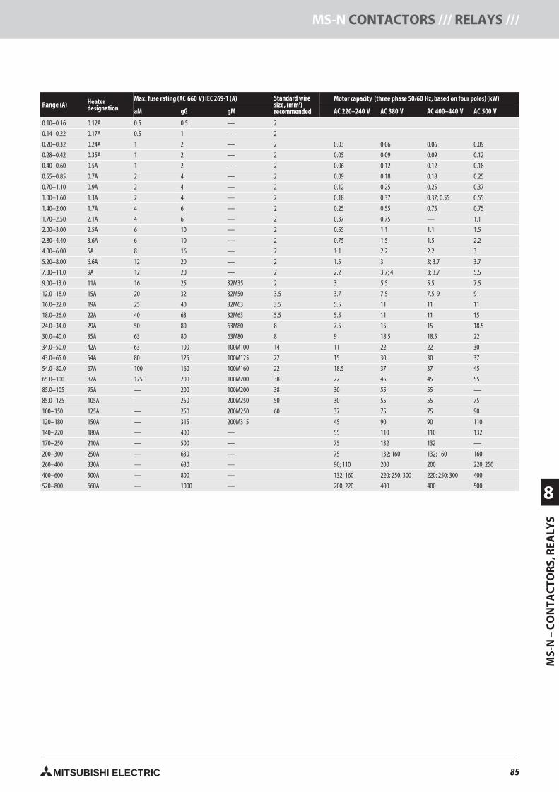
85MITSUBISHI ELECTRIC
MS-
N–
CO
NTA
CTO
RS,
REA
LYS
8
MS-N CONTACTORS /// RELAYS ///
Range (A) Heaterdesignation
Max. fuse rating (AC 660 V) IEC 269-1 (A) Standard wiresize, (mm2)recommended
Motor capacity (three phase 50/60 Hz, based on four poles) (kW)
aM gG gM AC 220–240 V AC 380 V AC 400–440 V AC 500 V
0.10–0.16 0.12A 0.5 0.5 — 2
0.14–0.22 0.17A 0.5 1 — 2
0.20–0.32 0.24A 1 2 — 2 0.03 0.06 0.06 0.09
0.28–0.42 0.35A 1 2 — 2 0.05 0.09 0.09 0.12
0.40–0.60 0.5A 1 2 — 2 0.06 0.12 0.12 0.18
0.55–0.85 0.7A 2 4 — 2 0.09 0.18 0.18 0.25
0.70–1.10 0.9A 2 4 — 2 0.12 0.25 0.25 0.37
1.00–1.60 1.3A 2 4 — 2 0.18 0.37 0.37; 0.55 0.55
1.40–2.00 1.7A 4 6 — 2 0.25 0.55 0.75 0.75
1.70–2.50 2.1A 4 6 — 2 0.37 0.75 — 1.1
2.00–3.00 2.5A 6 10 — 2 0.55 1.1 1.1 1.5
2.80–4.40 3.6A 6 10 — 2 0.75 1.5 1.5 2.2
4.00–6.00 5A 8 16 — 2 1.1 2.2 2.2 3
5.20–8.00 6.6A 12 20 — 2 1.5 3 3; 3.7 3.7
7.00–11.0 9A 12 20 — 2 2.2 3.7; 4 3; 3.7 5.5
9.00–13.0 11A 16 25 32M35 2 3 5.5 5.5 7.5
12.0–18.0 15A 20 32 32M50 3.5 3.7 7.5 7.5; 9 9
16.0–22.0 19A 25 40 32M63 3.5 5.5 11 11 11
18.0–26.0 22A 40 63 32M63 5.5 5.5 11 11 15
24.0–34.0 29A 50 80 63M80 8 7.5 15 15 18.5
30.0–40.0 35A 63 80 63M80 8 9 18.5 18.5 22
34.0–50.0 42A 63 100 100M100 14 11 22 22 30
43.0–65.0 54A 80 125 100M125 22 15 30 30 37
54.0–80.0 67A 100 160 100M160 22 18.5 37 37 45
65.0–100 82A 125 200 100M200 38 22 45 45 55
85.0–105 95A — 200 100M200 38 30 55 55 —
85.0–125 105A — 250 200M250 50 30 55 55 75
100–150 125A — 250 200M250 60 37 75 75 90
120–180 150A — 315 200M315 45 90 90 110
140–220 180A — 400 — 55 110 110 132
170–250 210A — 500 — 75 132 132 —
200–300 250A — 630 — 75 132; 160 132; 160 160
260–400 330A — 630 — 90; 110 200 200 220; 250
400–600 500A — 800 — 132; 160 220; 250; 300 220; 250; 300 400
520–800 660A — 1000 — 200; 220 400 400 500
85neue Seiten_GB.prnLVS-Family - Technical SectionFreitag, 30. Januar 2009 14:27:15
Farbprofil: DeaktiviertKomposit Standardbildschirm
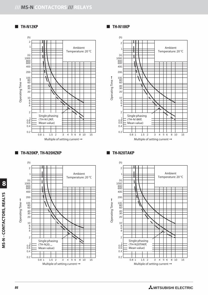
86 MITSUBISHI ELECTRIC
8
MS-
N–
CO
NTA
CTO
RS,
REA
LYS
/// MS-N CONTACTORS /// RELAYS
Ope
ratin
gT
ime
0.8
0.8
1 1.5 2 3 4 5 6 8 10 15
Multiples of setting current
0.2
0.40.6
1
2
468
10
2030406080
100
200
400600800
1000(s)
(h)
2
1
Ope
ratin
gT
ime
0.8
0.8
1 1.5 2 3 4 5 6 8 10 15
Multiples of setting current
0.2
0.40.6
1
2
468
10
2030406080
100
200
400600800
1000(s)
(h)
2
1
Ope
ratin
gT
ime
0.8
0.8
1 1.5 2 3 4 5 6 8 10 15
Multiples of setting current
0.2
0.40.6
1
2
468
10
2030406080
100
200
400600800
1000(s)
(h)
2
1
Ope
ratin
gT
ime
0.8
0.8
1 1.5 2 3 4 5 6 8 10 15
Multiples of setting current
0.2
0.40.6
1
2
468
10
2030406080
100
200
400600800
1000(s)
(h)
2
1
TH-N12KP TH-N18KP
TH-N20KP, TH-N20HZKP TH-N20TAKP
AmbientTemperature: 20 °C
AmbientTemperature: 20 °C
Op
erat
ing
Tim
e
Op
erat
ing
Tim
e
Single phasing(TH-N12KP,Mean value)
Multiple of setting current Multiple of setting current
Single phasing(TH-N18KP,Mean value)
AmbientTemperature: 20 °C
AmbientTemperature: 20 °C
Op
erat
ing
Tim
e
Op
erat
ing
Tim
e
Single phasing(TH-N20...,Mean value)
Single phasing(TH-N20TAKP,Mean value)
Multiple of setting current Multiple of setting current
86neue Seiten_GB.prnLVS-Family - Technical SectionFreitag, 30. Januar 2009 14:27:32
Farbprofil: DeaktiviertKomposit Standardbildschirm
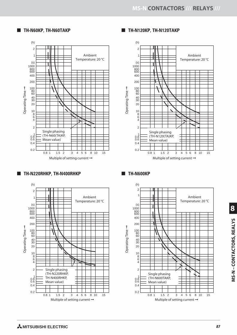
87MITSUBISHI ELECTRIC
MS-
N–
CO
NTA
CTO
RS,
REA
LYS
8
MS-N CONTACTORS /// RELAYS ///
Ope
ratin
gT
ime
0.8
0.8
1 1.5 2 3 4 5 6 8 10 15
Multiples of setting current
0.2
0.40.6
1
2
468
10
2030406080
100
200
400600800
1000(s)
(h)
2
1
Ope
ratin
gT
ime
0.8
0.8
1 1.5 2 3 4 5 6 8 10 15
Multiples of setting current
0.2
0.40.6
1
2
468
10
2030406080
100
200
400600800
1000(s)
(h)
2
1
Ope
ratin
gT
ime
0.8
0.8
1 1.5 2 3 4 5 6 8 10 15
Multiples of setting current
0.2
0.40.6
1
2
468
10
2030406080
100
200
400600800
1000(s)
(h)
2
1
Ope
ratin
gT
ime
0.8
0.8
1 1.5 2 3 4 5 6 8 10 15
Multiples of setting current
0.2
0.40.6
1
2
468
10
2030406080
100
200
400600800
1000(s)
(h)
2
1
TH-N60KP, TH-N60TAKP TH-N120KP, TH-N120TAKP
TH-N220RHKP, TH-N400RHKP TH-N600KP
AmbientTemperature: 20 °C
AmbientTemperature: 20 °C
Op
erat
ing
Tim
e
Op
erat
ing
Tim
e
Single phasing(TH-N60(TA)KP,Mean value)
Multiple of setting current Multiple of setting current
Single phasing(TH-N120(TA)KP,Mean value)
AmbientTemperature: 20 °C
AmbientTemperature: 20 °C
Op
erat
ing
Tim
e
Op
erat
ing
Tim
e
Single phasing(TH-N220RHKP,TH-N400RHKP,Mean value)
Single phasing(TH-N600TAKP,Mean value)
Multiple of setting current Multiple of setting current
87neue Seiten_GB.prnLVS-Family - Technical SectionFreitag, 30. Januar 2009 14:27:50
Farbprofil: DeaktiviertKomposit Standardbildschirm
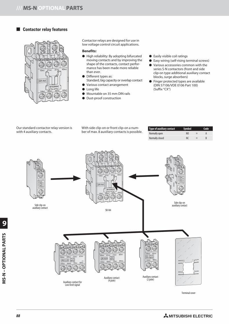
88 MITSUBISHI ELECTRIC
9
MS-
N–
OP
TIO
NA
LP
AR
TS/// MS-N OPTIONAL PARTS
Contactor relay features
Contactor relays are designed for use inlow voltage control circuit applications.
Benefits: High reliability: By adopting bifurcated
moving contacts and by improving theshape of the contacts, contact perfor-mance has been made more reliablethan ever.
Different types as:Standard, big capacity or overlap contact
Various contact arrangement Long life Mountable on 35 mm DIN rails Dust-proof construction
Easily visible coil ratings Easy wiring (self-rising terminal screws) Various accessories common with the
series S-N contactors (front and sideclip-on type additional auxiliary contactblocks, surge absorbers)
Finger protected types are available(DIN 57106/VDE 0106 Part 100)(Suffix “CX”)
54
54
Our standard contactor relay version iswith auxiliary contacts.
With side clip-on front clip-on a num-ber of is possible.
Type of auxiliary contact Symbol Code
Normally open NO = A
Normally closed NC = B
SR-N4
Side clip-onauxiliary contact
Auxiliary contact forLow level signal
Auxiliary contact(4 pole)
Auxiliary contact(2 pole)
Side clip-onauxiliary contact
Terminal cover
88neue Seiten_GB.prnLVS-Family - Technical SectionFreitag, 30. Januar 2009 14:28:03
Farbprofil: DeaktiviertKomposit Standardbildschirm
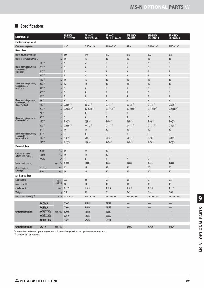
89MITSUBISHI ELECTRIC
MS-
N–
OP
TIO
NA
LP
AR
TS9
MS-N OPTIONAL PARTS ///
Specifications SR-N4CXACV4A
SR-N4CXACV3A1B
SR-N4CXACV2A2B
SRD-N4CXDC24V4A
SRD-N4CXDC24V3A1B
SRD-N4CXDC24V2A2B
Contact arrangement
Contact arrangement 4 NO 3 NO + 1 NC 2 NO + 2 NC 4 NO 3 NO + 1 NC 2 NO + 2 NC
Rated data
Rated insulation voltage V 690 690 690 690 690 690
Rated continuous current Ith A 16 16 16 16 16 16
Rated operating current;Category AC-15(coil load)
110 V A 6 6 6 6 6 6
230 V A 5 5 5 5 5 5
440 V A 3 3 3 3 3 3
550 V A 3 3 3 3 3 3
Rated operating current;Category AC-12(coil load)
110 V A 16 16 16 16 16 16
230 V A 12 12 12 12 12 12
440 V A 5 5 5 5 5 5
550 V A 5 5 5 5 5 5
Rated operating current;Category DC-13(large coil load)
24 V A 5 5 5 5 5 5
48 V A 3 3 3 3 3 3
110 V A 0.8 (2) 0.8 (2) 0.8 (2) 0.8 (2) 0.8 (2) 0.8 (2)
220 V A 0.2 (0.8) 0.2 (0.8) 0.2 (0.8) 0.2 (0.8) 0.2 (0.8) 0.2 (0.8)
Rated operating current;Category DC-14
24 V A 8 8 8 8 8 8
48 V A 3 3 3 3 3 3
110 V A 2 (4) 2 (4) 2 (4) 2 (4) 2 (4) 2 (4)
220 V A 0.4 (1) 0.4 (1) 0.4 (1) 0.4 (1) 0.4 (1) 0.4 (1)
Rated operating current;Category DC-12(resistive load)
24 V A 10 10 10 10 10 10
48 V A 8 8 8 8 8 8
110 V A 5 (8) 5 (8) 5 (8) 5 (8) 5 (8) 5 (8)
220 V A 1 (3) 1 (3) 1 (3) 1 (3) 1 (3) 1 (3)
Electrical data
Coil consumption(at rated coil voltage)
Inrush VA 60 60 60 — — —
Sealed VA 10 10 10 — — —
Watts W 3 3 3 7 7 7
Switching frequency oper./h 1,800 1,800 1,800 1,800 1,800 1,800
Operating time(average)
Making ms 15 15 15 50 50 50
Breaking ms 10 10 10 10 10 10
Mechanical data
Electrical life Oper.(million)
0.5 0.5 0.5 0.5 0.5 0.5
Mechanical life 10 10 10 10 10 10
Conductor size mm2 1–2.5 1–2.5 1–2.5 1–2.5 1–2.5 1–2.5
Weight kg 0.3 0.3 0.3 0.62 0.62 0.62
Dimensions (WxHxD) mm 43 x 78 x 78 43 x 78 x 78 43 x 78 x 78 43 x 78 x 110 43 x 78 x 110 43 x 78 x 110
Order information
AC24V
Art. no.
52607 52612 52617 — — —
AC48V 52608 52613 52618 — — —
AC120V 52609 52614 52619 — — —
AC230V 52610 52615 52620 — — —
AC400V 52611 52616 52621 — — —
Order information DC24V Art. no. — — — 52622 52623 52624 Parenthesized rated operating current is for switching the load in 2-pole series connection. Dimensions on request.
Specifications
89neue Seiten_GB.prnLVS-Family - Technical SectionFreitag, 30. Januar 2009 14:28:09
Farbprofil: DeaktiviertKomposit Standardbildschirm
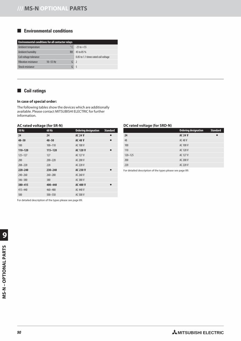
90 MITSUBISHI ELECTRIC
9
MS-
N–
OP
TIO
NA
LP
AR
TS/// MS-N OPTIONAL PARTS
In case of special order:
The following tables show the devices which are additionallyavailable. Please contact MITSUBISHI ELECTRIC for furtherinformation.
Environmental conditions
Coil ratings
AC rated voltage (for SR-N)50 Hz 60 Hz Ordering designation Standard
AC 24 V •48–50 48–50 AC 48 V •100 100–110 AC 100 V
110–120 115–120 AC 120 V •125–127 127 AC 127 V
200 200–220 AC 200 V
208–220 220 AC 220 V
220–240 230–240 AC 230 V •240–260 260–280 AC 260 V
346–380 380 AC 380 V
380–415 400–440 AC 400 V •415–440 460–480 AC 440 V
500 500–550 AC 500 V
For detailed description of the types please see page 89.
DC rated voltage (for SRD-N)Ordering designation Standard
24 AC 24 V •48 AC 48 V
100 AC 100 V
110 AC 120 V
120–125 AC 127 V
200 AC 200 V
220 AC 220 V
For detailed description of the types please see page 89.
Environmental conditions for all contactor relays
Ambient temperature ° C -25 to +55
Ambient humidity RH 45 to 85 %
Coil voltage tolerance 0.85 to 1.1 times rated coil voltage
Vibration resistance 10–55 Hz G 2
Shock resistance G 5
90neue Seiten_GB.prnLVS-Family - Technical SectionFreitag, 30. Januar 2009 14:28:15
Farbprofil: DeaktiviertKomposit Standardbildschirm
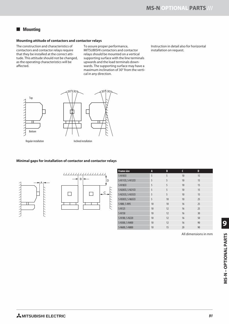
91MITSUBISHI ELECTRIC
MS-
N–
OP
TIO
NA
LP
AR
TS9
MS-N OPTIONAL PARTS ///
Mounting attitude of contactors and contactor relays
The construction and characteristics ofcontactors and contactor relays requirethat they be installed at the correct atti-tude. This attitude should not be changed,as the operating characteristics will beaffected.
To assure proper performance,MITSUBISHI contactors and contactorrelays should be mounted on a verticalsupporting surface with the line terminalsupwards and the load terminals down-wards. The supporting surface may have amaximum inclination of 30° from the verti-cal in any direction.
Instruction in detail also for horizontalinstallation on request.
30° 30°30° 30°
AB
C
D
Mounting
Top
Bottom
Regular installation Inclined installation
Minimal gaps for installation of contactor and contactor relays
Frame size A B C D
S-N10CX 5 5 10 15
S-N11CX, S-N12CX 5 5 10 15
S-N18CX 5 5 10 15
S-N20CX, S-N21CX 5 5 10 15
S-N25CX, S-N35CX 5 5 10 15
S-N50CX, S-N65CX 5 10 10 25
S-N80, S-N95 10 10 16 25
S-N125 10 12 16 25
S-N150 10 12 16 30
S-N180, S-N220 10 12 16 50
S-N300, S-N400 10 12 16 90
S-N600, S-N800 10 15 20 90
All dimensions in mm
91neue Seiten_GB.prnLVS-Family - Technical SectionFreitag, 30. Januar 2009 14:28:24
Farbprofil: DeaktiviertKomposit Standardbildschirm
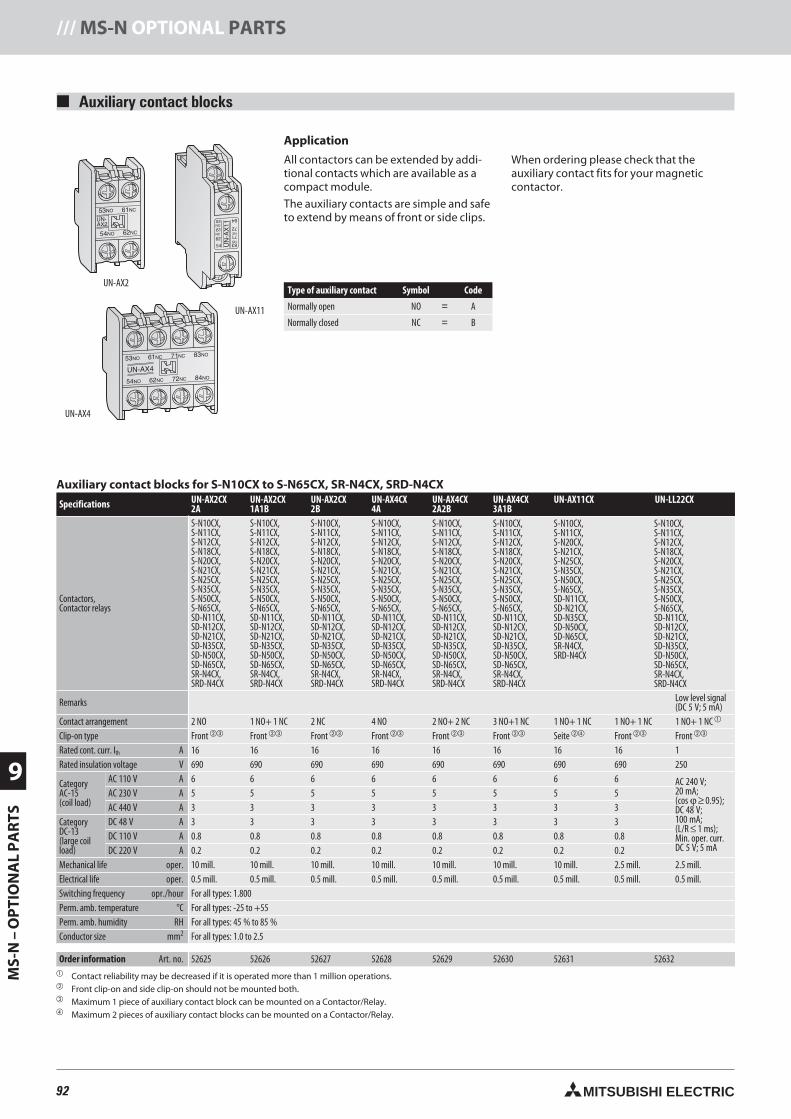
92 MITSUBISHI ELECTRIC
9
MS-
N–
OP
TIO
NA
LP
AR
TS/// MS-N OPTIONAL PARTS
Auxiliary contact blocks
UN-AX2
UN-AX4
UN-AX11
Application
All contactors can be extended by addi-tional contacts which are available as acompact module.
The auxiliary contacts are simple and safeto extend by means of front or side clips.
When ordering please check that theauxiliary contact fits for your magneticcontactor.
Auxiliary contact blocks for S-N10CX to S-N65CX, SR-N4CX, SRD-N4CX
Specifications UN-AX2CX2A
UN-AX2CX1A1B
UN-AX2CX2B
UN-AX4CX4A
UN-AX4CX2A2B
UN-AX4CX3A1B
UN-AX11CX UN-LL22CX
Contactors,Contactor relays
S-N10CX,S-N11CX,S-N12CX,S-N18CX,S-N20CX,S-N21CX,S-N25CX,S-N35CX,S-N50CX,S-N65CX,SD-N11CX,SD-N12CX,SD-N21CX,SD-N35CX,SD-N50CX,SD-N65CX,SR-N4CX,SRD-N4CX
S-N10CX,S-N11CX,S-N12CX,S-N18CX,S-N20CX,S-N21CX,S-N25CX,S-N35CX,S-N50CX,S-N65CX,SD-N11CX,SD-N12CX,SD-N21CX,SD-N35CX,SD-N50CX,SD-N65CX,SR-N4CX,SRD-N4CX
S-N10CX,S-N11CX,S-N12CX,S-N18CX,S-N20CX,S-N21CX,S-N25CX,S-N35CX,S-N50CX,S-N65CX,SD-N11CX,SD-N12CX,SD-N21CX,SD-N35CX,SD-N50CX,SD-N65CX,SR-N4CX,SRD-N4CX
S-N10CX,S-N11CX,S-N12CX,S-N18CX,S-N20CX,S-N21CX,S-N25CX,S-N35CX,S-N50CX,S-N65CX,SD-N11CX,SD-N12CX,SD-N21CX,SD-N35CX,SD-N50CX,SD-N65CX,SR-N4CX,SRD-N4CX
S-N10CX,S-N11CX,S-N12CX,S-N18CX,S-N20CX,S-N21CX,S-N25CX,S-N35CX,S-N50CX,S-N65CX,SD-N11CX,SD-N12CX,SD-N21CX,SD-N35CX,SD-N50CX,SD-N65CX,SR-N4CX,SRD-N4CX
S-N10CX,S-N11CX,S-N12CX,S-N18CX,S-N20CX,S-N21CX,S-N25CX,S-N35CX,S-N50CX,S-N65CX,SD-N11CX,SD-N12CX,SD-N21CX,SD-N35CX,SD-N50CX,SD-N65CX,SR-N4CX,SRD-N4CX
S-N10CX,S-N11CX,S-N20CX,S-N21CX,S-N25CX,S-N35CX,S-N50CX,S-N65CX,SD-N11CX,SD-N21CX,SD-N35CX,SD-N50CX,SD-N65CX,SR-N4CX,SRD-N4CX
S-N10CX,S-N11CX,S-N12CX,S-N18CX,S-N20CX,S-N21CX,S-N25CX,S-N35CX,S-N50CX,S-N65CX,SD-N11CX,SD-N12CX,SD-N21CX,SD-N35CX,SD-N50CX,SD-N65CX,SR-N4CX,SRD-N4CX
Remarks Low level signal(DC 5 V; 5 mA)
Contact arrangement 2 NO 1 NO+ 1 NC 2 NC 4 NO 2 NO+ 2 NC 3 NO+1 NC 1 NO+ 1 NC 1 NO+ 1 NC 1 NO+ 1 NC
Clip-on type Front Front Front Front Front Front Seite Front Front
Rated cont. curr. Ith A 16 16 16 16 16 16 16 16 1Rated insulation voltage V 690 690 690 690 690 690 690 690 250
CategoryAC-15(coil load)
AC 110 V A 6 6 6 6 6 6 6 6 AC 240 V;20 mA;(cos ϕ ≥ 0.95);DC 48 V;100 mA;(L/R ≤ 1 ms);Min. oper. curr.DC 5 V; 5 mA
AC 230 V A 5 5 5 5 5 5 5 5AC 440 V A 3 3 3 3 3 3 3 3
CategoryDC-13(large coilload)
DC 48 V A 3 3 3 3 3 3 3 3DC 110 V A 0.8 0.8 0.8 0.8 0.8 0.8 0.8 0.8DC 220 V A 0.2 0.2 0.2 0.2 0.2 0.2 0.2 0.2
Mechanical life oper. 10 mill. 10 mill. 10 mill. 10 mill. 10 mill. 10 mill. 10 mill. 2.5 mill. 2.5 mill.Electrical life oper. 0.5 mill. 0.5 mill. 0.5 mill. 0.5 mill. 0.5 mill. 0.5 mill. 0.5 mill. 0.5 mill. 0.5 mill.Switching frequency opr./hour For all types: 1.800Perm. amb. temperature °C For all types: -25 to +55Perm. amb. humidity RH For all types: 45 % to 85 %Conductor size mm2 For all types: 1.0 to 2.5
Order information Art. no. 52625 52626 52627 52628 52629 52630 52631 52632 Contact reliability may be decreased if it is operated more than 1 million operations. Front clip-on and side clip-on should not be mounted both. Maximum 1 piece of auxiliary contact block can be mounted on a Contactor/Relay. Maximum 2 pieces of auxiliary contact blocks can be mounted on a Contactor/Relay.
Type of auxiliary contact Symbol Code
Normally open NO = A
Normally closed NC = B
92neue Seiten_GB.prnLVS-Family - Technical SectionFreitag, 30. Januar 2009 14:28:35
Farbprofil: DeaktiviertKomposit Standardbildschirm
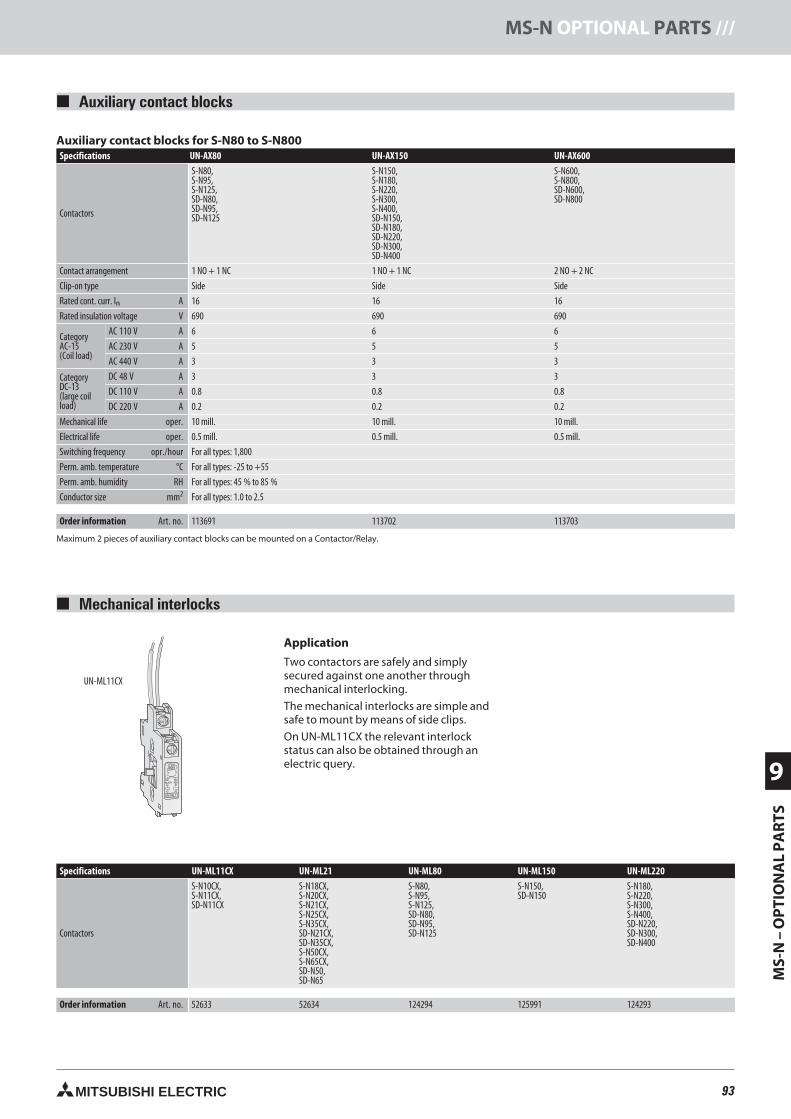
93MITSUBISHI ELECTRIC
MS-
N–
OP
TIO
NA
LP
AR
TS9
MS-N OPTIONAL PARTS ///
Mechanical interlocks
UN-ML11CX
Application
Two contactors are safely and simplysecured against one another throughmechanical interlocking.
The mechanical interlocks are simple andsafe to mount by means of side clips.
On UN-ML11CX the relevant interlockstatus can also be obtained through anelectric query.
Specifications UN-ML11CX UN-ML21 UN-ML80 UN-ML150 UN-ML220
Contactors
S-N10CX,S-N11CX,SD-N11CX
S-N18CX,S-N20CX,S-N21CX,S-N25CX,S-N35CX,SD-N21CX,SD-N35CX,S-N50CX,S-N65CX,SD-N50,SD-N65
S-N80,S-N95,S-N125,SD-N80,SD-N95,SD-N125
S-N150,SD-N150
S-N180,S-N220,S-N300,S-N400,SD-N220,SD-N300,SD-N400
Order information Art. no. 52633 52634 124294 125991 124293
Auxiliary contact blocks for S-N80 to S-N800Specifications UN-AX80 UN-AX150 UN-AX600
Contactors
S-N80,S-N95,S-N125,SD-N80,SD-N95,SD-N125
S-N150,S-N180,S-N220,S-N300,S-N400,SD-N150,SD-N180,SD-N220,SD-N300,SD-N400
S-N600,S-N800,SD-N600,SD-N800
Contact arrangement 1 NO + 1 NC 1 NO + 1 NC 2 NO + 2 NC
Clip-on type Side Side Side
Rated cont. curr. Ith A 16 16 16
Rated insulation voltage V 690 690 690
CategoryAC-15(Coil load)
AC 110 V A 6 6 6
AC 230 V A 5 5 5
AC 440 V A 3 3 3
CategoryDC-13(large coilload)
DC 48 V A 3 3 3
DC 110 V A 0.8 0.8 0.8
DC 220 V A 0.2 0.2 0.2
Mechanical life oper. 10 mill. 10 mill. 10 mill.
Electrical life oper. 0.5 mill. 0.5 mill. 0.5 mill.
Switching frequency opr./hour For all types: 1,800
Perm. amb. temperature °C For all types: -25 to +55
Perm. amb. humidity RH For all types: 45 % to 85 %
Conductor size mm2 For all types: 1.0 to 2.5
Order information Art. no. 113691 113702 113703
Maximum 2 pieces of auxiliary contact blocks can be mounted on a Contactor/Relay.
Auxiliary contact blocks
93neue Seiten_GB.prnLVS-Family - Technical SectionFreitag, 30. Januar 2009 14:28:43
Farbprofil: DeaktiviertKomposit Standardbildschirm
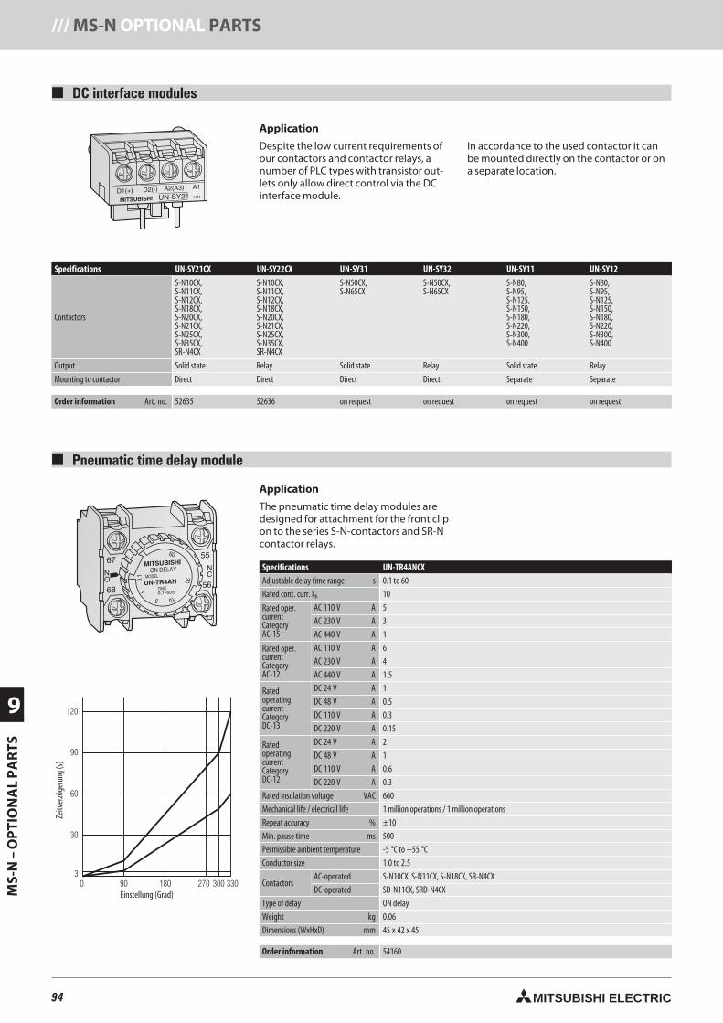
94 MITSUBISHI ELECTRIC
9
MS-
N–
OP
TIO
NA
LP
AR
TS/// MS-N OPTIONAL PARTS
DC interface modules
Application
Despite the low current requirements ofour contactors and contactor relays, anumber of PLC types with transistor out-lets only allow direct control via the DCinterface module.
In accordance to the used contactor it canbe mounted directly on the contactor or ona separate location.
Specifications UN-SY21CX UN-SY22CX UN-SY31 UN-SY32 UN-SY11 UN-SY12
Contactors
S-N10CX,S-N11CX,S-N12CX,S-N18CX,S-N20CX,S-N21CX,S-N25CX,S-N35CX,SR-N4CX
S-N10CX,S-N11CX,S-N12CX,S-N18CX,S-N20CX,S-N21CX,S-N25CX,S-N35CX,SR-N4CX
S-N50CX,S-N65CX
S-N50CX,S-N65CX
S-N80,S-N95,S-N125,S-N150,S-N180,S-N220,S-N300,S-N400
S-N80,S-N95,S-N125,S-N150,S-N180,S-N220,S-N300,S-N400
Output Solid state Relay Solid state Relay Solid state Relay
Mounting to contactor Direct Direct Direct Direct Separate Separate
Order information Art. no. 52635 52636 on request on request on request on request
Pneumatic time delay module
Application
The pneumatic time delay modules aredesigned for attachment for the front clipon to the series S-N-contactors and SR-Ncontactor relays.
Specifications UN-TR4ANCXAdjustable delay time range s 0.1 to 60Rated cont. curr. Ith 10
Rated oper.currentCategoryAC-15
AC 110 V A 5AC 230 V A 3AC 440 V A 1
Rated oper.currentCategoryAC-12
AC 110 V A 6AC 230 V A 4AC 440 V A 1.5
RatedoperatingcurrentCategoryDC-13
DC 24 V A 1DC 48 V A 0.5DC 110 V A 0.3DC 220 V A 0.15
RatedoperatingcurrentCategoryDC-12
DC 24 V A 2DC 48 V A 1DC 110 V A 0.6DC 220 V A 0.3
Rated insulation voltage VAC 660Mechanical life / electrical life 1 million operations / 1 million operationsRepeat accuracy % ±10Min. pause time ms 500Permissible ambient temperature -5 °C to +55 °CConductor size 1.0 to 2.5
ContactorsAC-operated S-N10CX, S-N11CX, S-N18CX, SR-N4CXDC-operated SD-N11CX, SRD-N4CX
Type of delay ON delayWeight kg 0.06Dimensions (WxHxD) mm 45 x 42 x 45
Order information Art. no. 54160
Tim
e dela
y (se
c.)
0 90 180 270 300 330Dial rotation (degrees)
3
30
60
90
120
Zeitv
erzö
geru
ng(s)
Einstellung (Grad)
94neue Seiten_GB.prnLVS-Family - Technical SectionFreitag, 30. Januar 2009 14:28:56
Farbprofil: DeaktiviertKomposit Standardbildschirm
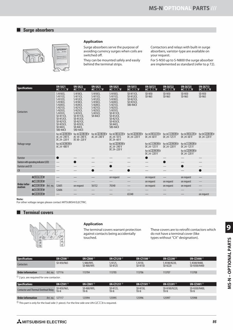
95MITSUBISHI ELECTRIC
MS-
N–
OP
TIO
NA
LP
AR
TS9
MS-N OPTIONAL PARTS ///
Surge absorbers
Application
Surge absorbers serve the purpose ofavoiding currency surges when coils areswitched off.
They can be mounted safely and easilybehind the terminal strips.
Contactors and relays with built-in surgeabsorbers, varistor-type are available onyour request.
For S-N50 up to S-N800 the surge absorberare implemented as standard (refer to p 72).
Specifications UN-SA21ACV
UN-SA22ACV
UN-SA23ACV
UN-SA25ACV
UN-SA13DCV
UN-SA721ACV
UN-SA722ACV
UN-SA725ACV
UN-SA713DCV
Contactors
S-N10CX,S-N11CX,S-N12CX,S-N18CX,S-N20CX,S-N21CX,S-N25CX,S-N35CX,SD-N11CX,SD-N12CX,SD-N21CX,SD-N35CX,SR-N4CX,SRD-N4CX
S-N10CX,S-N11CX,S-N12CX,S-N18CX,S-N20CX,S-N21CX,S-N25CX,S-N35CX,SD-N11CX,SD-N12CX,SD-N21CX,SD-N35CX,SR-N4CX,SRD-N4CX
S-N10CX,S-N11CX,S-N12CX,S-N18CX,S-N20CX,S-N21CX,S-N25CX,S-N35CX,SR-N4CX
S-N10CX,S-N11CX,S-N18CX,S-N20CX,S-N21CX,S-N25CX,S-N35CX,SD-N11CX,SD-N12CX,SD-N21CX,SD-N35CX,SR-N4CX,SRD-N4CX
SD-N11CX,SD-N12CX,SD-N21CX,SD-N35CX,SRD-N4CX
SD-N50SD-N65
SD-N50SD-N65
SD-N50SD-N65
SD-N50SD-N65
Voltage range
for AC200VAC 24–240 V,DC 24–220 V
for AC200VAC 50–240 V,DC 60–220 V
for AC200VAC 24–240 V
for AC048VAC 24–50 V,DC 24–60 V
for DC200VDC 24–220 V
for AC048VDC 24–60 V
for AC100VDC 24–125 V
for AC048VDC 24–60 V
for DC200VDC 24–220 V
for AC400VAC 24–480 V
for AC200VAC 24–240 VDC 24–220 V
for AC100VDC 24–125 V
for AC200VDC 24–220 V
for AC100VDC 24–125 V
for AC200VDC 24–220 V
for AC200VDC 24–220 V
Varistor — — — — — — —Varistorwithoperatingindicator(LED) — — — — — — —Varistor and CR — — — — — — —CR — — — — — —
Order infor-mation
AC048V
Art. no.
— — — on request — on request — on request —AC100V — — — — — on request on request on request —AC200V 52605 on request 56152 70340 — on request on request on request —AC400V 52606 — — — — — — — —DC200V — — — — 65340 — — — on request
Note:For other voltage ranges please contact MITSUBISHI ELECTRIC.
Terminal covers
Application
The terminal covers warrant protectionagainst contacts being accidentallytouched.
These covers are to retrofit contactors whichdo not have a terminal cover (liketypes without “CX” designation).
Specifications UN-CZ500 UN-CZ800 UN-CZ1250 UN-CZ1500 UN-CZ2200 UN-CZ3000
Contactors SD-N50/N65 S-N80/N95,SD-N80/N95
S-N125,SD-N125
S-N150,SD-N150
S-N180/N220,SD-N220
S-N300/N400,SD-N300/N400
Order information Art. no. 127116 113704 113705 113706 113707 113708 2 pcs. are required for one contactor .
Specifications UN-CZ501 UN-CZ801 UN-CZ1251 UN-CZ1501 UN-CZ2201 UN-CZ3001
Contactor and Thermal Overheat Relay SD-N50/N65,TH-N
SD-N80/N95,TH-N
SD-N125,TH-N
SD-N150,TH-N
SD-N180/N220,TH-N
SD-N300/N400,TH-N
Order information Art. no. 127117 125994 125995 125996 125997 125998 This part is only for the load side (1 piece). For the line side one UN-CZ0 is required.
95neue Seiten_GB.prnLVS-Family - Technical SectionFreitag, 30. Januar 2009 14:29:12
Farbprofil: DeaktiviertKomposit Standardbildschirm
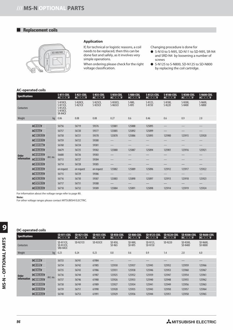
96 MITSUBISHI ELECTRIC
9
MS-
N–
OP
TIO
NA
LP
AR
TS/// MS-N OPTIONAL PARTS
Replacement coils
Application
If, for technical or logistic reasons, a coilneeds to be replaced, then this can bedone fast and safely, as it involves verysimple operations.
When ordering please check for the rightvoltage classification.
Changing procedure is done for S-N10 to S-N95, SD-N11 to SD-N95, SR-N4
and SRD-N4 by loosening a number ofscrews
S-N125 to S-N800, SD-N125 to SD-N800by replacing the coil cartridge.
AC-operated coils
Specifications S-N11-COILACV
S-N21-COILACV
S-N35-COILACV
S-N50-COILACV
S-N80-COILACV
S-N125-COILACV
S-N180-COILACV
S-N300-COILACV
S-N600-COILACV
Contactors
S-N10CX,S-N11CX,S-N12CX,S-N18CX,SR-N4CX
S-N20CX,S-N21CX
S-N25CX,S-N35CX
S-N50CX,S-N65CX
S-N80,S-N95
S-N125,S-N150
S-N180,S-N220
S-N300,S-N400
S-N600,S-N800
Weight kg 0.06 0.08 0.08 0.27 0.6 0.46 0.6 0.9 2.0
Orderinformation
AC24V
Art. no.
56756 56719 59376 125881 125888 125895 — — —
AC48V 56757 56720 59377 125885 125892 125899 — — —
AC100V 56758 56721 59378 125878 125886 125893 125900 125915 125920
AC120V 56759 56722 59380 — — — — — —
AC127V 56760 56724 59381 — — — — — —
AC200V 56679 56725 59382 125880 125887 125894 125901 125916 125921
AC220V 56680 56726 59383 — — — — — —
AC230V 56713 56727 59384 — — — — — —
AC260V 56714 56728 59385 — — — — — —
AC300V on request on request on request 125882 125889 125896 125912 125917 125922
AC380V 56715 56729 59386 — — — — — —
AC400V 56716 56730 59387 125883 125890 125897 125913 125918 125923
AC440V 56717 56731 59388 — — — — — —
AC500V 56718 56732 59389 125884 125891 125898 125914 125919 125924
For information about the voltage range refer to page 80.Note:For other voltage ranges please contact MITSUBISHI ELECTRIC.
DC-operated coils
Specifications SD-N11-COILDCV
SD-N21-COILDCV
SD-N35-COILDCV
SD-N50-COILDCV
SD-N80-COILDCV
SD-N125-COILDCV
SD-N220-COILDCV
SD-N300-COILDCV
SD-N600-COILDCV
ContactorsSD-N11CX,SD-N12CX,SRD-N4CX
SD-N21CX SD-N35CX SD-N50,SD-N65
SD-N80,SD-N95
SD-N125,SD-N150
SD-N220 SD-N300,SD-N400
SD-N600,SD-N800
Weight kg 0.23 0.24 0.23 0.8 0.6 0.9 1.4 2.0 6.0
Orderinformation
DC12V
Art. no.
56733 56741 61984 — — — — — —
DC24V 56734 56742 61985 125930 125937 125945 125952 125959 125966
DC48V 56735 56743 61986 125931 125938 125946 125953 125960 125967
DC100V 56736 56744 61987 125925 125932 125939 125947 125954 125961
DC110V 56737 56746 61988 125926 125933 125940 125948 125955 125962
DC125V 56738 56749 61989 125927 125934 125941 125949 125956 125963
DC200V 56739 56751 61990 125928 125935 125943 125950 125957 125964
DC220V 56740 56753 61991 125929 125936 125944 125951 125958 125965
96neue Seiten_GB.prnLVS-Family - Technical SectionFreitag, 30. Januar 2009 14:29:21
Farbprofil: DeaktiviertKomposit Standardbildschirm
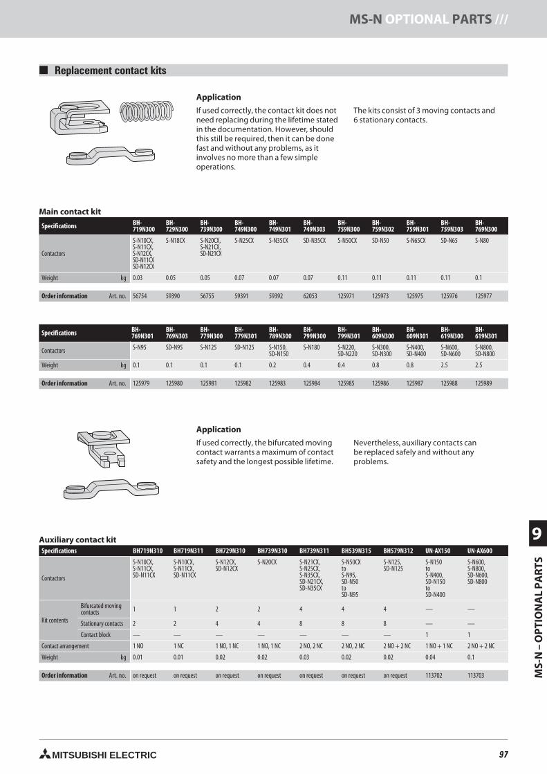
97MITSUBISHI ELECTRIC
MS-
N–
OP
TIO
NA
LP
AR
TS9
MS-N OPTIONAL PARTS ///
Replacement contact kits
Application
If used correctly, the contact kit does notneed replacing during the lifetime statedin the documentation. However, shouldthis still be required, then it can be donefast and without any problems, as itinvolves no more than a few simpleoperations.
The kits consist of 3 moving contacts and6 stationary contacts.
Main contact kit
Specifications BH-719N300
BH-729N300
BH-739N300
BH-749N300
BH-749N301
BH-749N303
BH-759N300
BH-759N302
BH-759N301
BH-759N303
BH-769N300
Contactors
S-N10CX,S-N11CX,S-N12CX,SD-N11CXSD-N12CX
S-N18CX S-N20CX,S-N21CX,SD-N21CX
S-N25CX S-N35CX SD-N35CX S-N50CX SD-N50 S-N65CX SD-N65 S-N80
Weight kg 0.03 0.05 0.05 0.07 0.07 0.07 0.11 0.11 0.11 0.11 0.1
Order information Art. no. 56754 59390 56755 59391 59392 62053 125971 125973 125975 125976 125977
Specifications BH-769N301
BH-769N303
BH-779N300
BH-779N301
BH-789N300
BH-799N300
BH-799N301
BH-609N300
BH-609N301
BH-619N300
BH-619N301
Contactors S-N95 SD-N95 S-N125 SD-N125 S-N150,SD-N150
S-N180 S-N220,SD-N220
S-N300,SD-N300
S-N400,SD-N400
S-N600,SD-N600
S-N800,SD-N800
Weight kg 0.1 0.1 0.1 0.1 0.2 0.4 0.4 0.8 0.8 2.5 2.5
Order information Art. no. 125979 125980 125981 125982 125983 125984 125985 125986 125987 125988 125989
Auxiliary contact kitSpecifications BH719N310 BH719N311 BH729N310 BH739N310 BH739N311 BH539N315 BH579N312 UN-AX150 UN-AX600
Contactors
S-N10CX,S-N11CX,SD-N11CX
S-N10CX,S-N11CX,SD-N11CX
S-N12CX,SD-N12CX
S-N20CX S-N21CX,S-N25CX,S-N35CX,SD-N21CX,SD-N35CX
S-N50CXtoS-N95,SD-N50toSD-N95
S-N125,SD-N125
S-N150toS-N400,SD-N150toSD-N400
S-N600,S-N800,SD-N600,SD-N800
Kit contents
Bifurcated movingcontacts 1 1 2 2 4 4 4 — —
Stationary contacts 2 2 4 4 8 8 8 — —
Contact block — — — — — — — 1 1
Contact arrangement 1 NO 1 NC 1 NO, 1 NC 1 NO, 1 NC 2 NO, 2 NC 2 NO, 2 NC 2 NO + 2 NC 1 NO + 1 NC 2 NO + 2 NC
Weight kg 0.01 0.01 0.02 0.02 0.03 0.02 0.02 0.04 0.1
Order information Art. no. on request on request on request on request on request on request on request 113702 113703
Application
If used correctly, the bifurcated movingcontact warrants a maximum of contactsafety and the longest possible lifetime.
Nevertheless, auxiliary contacts canbe replaced safely and without anyproblems.
97neue Seiten_GB.prnLVS-Family - Technical SectionFreitag, 30. Januar 2009 14:29:31
Farbprofil: DeaktiviertKomposit Standardbildschirm
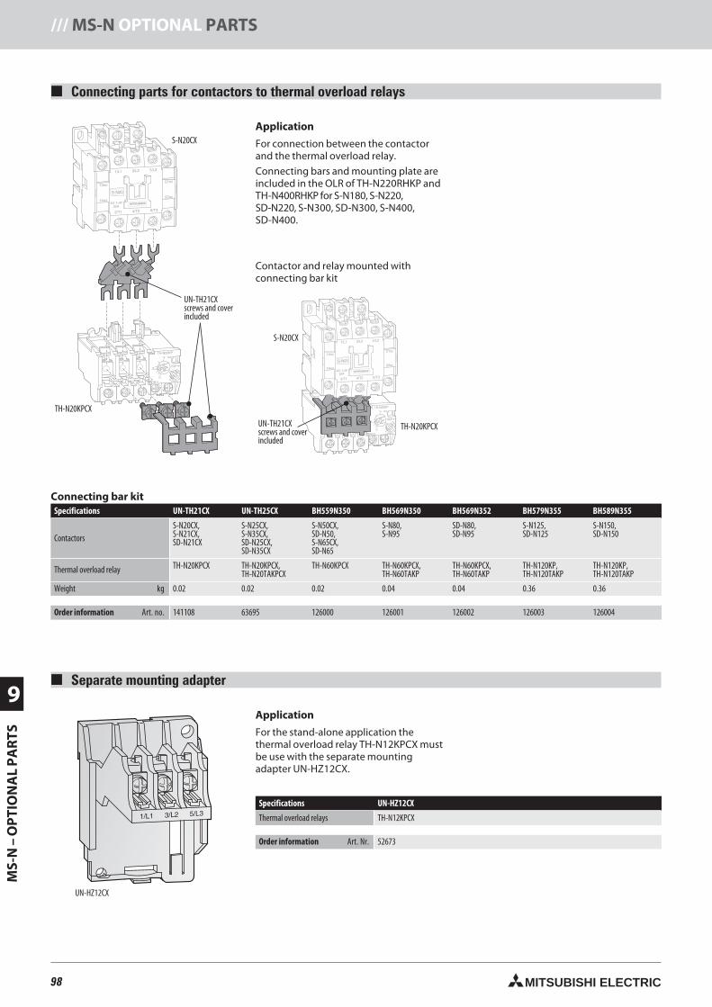
98 MITSUBISHI ELECTRIC
9
MS-
N–
OP
TIO
NA
LP
AR
TS/// MS-N OPTIONAL PARTS
Connecting parts for contactors to thermal overload relays
Application
For connection between the contactorand the thermal overload relay.
Connecting bars and mounting plate areincluded in the OLR of TH-N220RHKP andTH-N400RHKP for S-N180, S-N220,SD-N220, S-N300, SD-N300, S-N400,SD-N400.
S-N20CX
Connecting bar kitSpecifications UN-TH21CX UN-TH25CX BH559N350 BH569N350 BH569N352 BH579N355 BH589N355
ContactorsS-N20CX,S-N21CX,SD-N21CX
S-N25CX,S-N35CX,SD-N25CX,SD-N35CX
S-N50CX,SD-N50,S-N65CX,SD-N65
S-N80,S-N95
SD-N80,SD-N95
S-N125,SD-N125
S-N150,SD-N150
Thermal overload relay TH-N20KPCX TH-N20KPCX,TH-N20TAKPCX
TH-N60KPCX TH-N60KPCX,TH-N60TAKP
TH-N60KPCX,TH-N60TAKP
TH-N120KP,TH-N120TAKP
TH-N120KP,TH-N120TAKP
Weight kg 0.02 0.02 0.02 0.04 0.04 0.36 0.36
Order information Art. no. 141108 63695 126000 126001 126002 126003 126004
Separate mounting adapter
Specifications UN-HZ12CX
Thermal overload relays TH-N12KPCX
Order information Art. Nr. 52673
UN-HZ12CX
Application
For the stand-alone application thethermal overload relay TH-N12KPCX mustbe use with the separate mountingadapter UN-HZ12CX.
UN-TH21CXscrews and coverincluded
TH-N20KPCX
Contactor and relay mounted withconnecting bar kit
S-N20CX
UN-TH21CXscrews and coverincluded
TH-N20KPCX
98neue Seiten_GB.prnLVS-Family - Technical SectionFreitag, 30. Januar 2009 14:29:44
Farbprofil: DeaktiviertKomposit Standardbildschirm
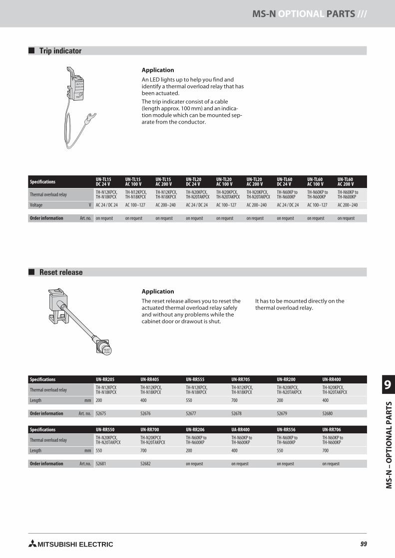
99MITSUBISHI ELECTRIC
MS-
N–
OP
TIO
NA
LP
AR
TS9
MS-N OPTIONAL PARTS ///
Reset release
Trip indicator
Application
An LED lights up to help you find andidentify a thermal overload relay that hasbeen actuated.
The trip indicater consist of a cable(length approx. 100 mm) and an indica-tion module which can be mounted sep-arate from the conductor.
Specifications UN-TL15DC 24 V
UN-TL15AC 100 V
UN-TL15AC 200 V
UN-TL20DC 24 V
UN-TL20AC 100 V
UN-TL20AC 200 V
UN-TL60DC 24 V
UN-TL60AC 100 V
UN-TL60AC 200 V
Thermal overload relay TH-N12KPCX,TH-N18KPCX
TH-N12KPCX,TH-N18KPCX
TH-N12KPCX,TH-N18KPCX
TH-N20KPCX,TH-N20TAKPCX
TH-N20KPCX,TH-N20TAKPCX
TH-N20KPCX,TH-N20TAKPCX
TH-N60KP toTH-N600KP
TH-N60KP toTH-N600KP
TH-N60KP toTH-N600KP
Voltage V AC 24 / DC 24 AC 100–127 AC 200–240 AC 24 / DC 24 AC 100–127 AC 200–240 AC 24 / DC 24 AC 100–127 AC 200–240
Order information Art. no. on request on request on request on request on request on request on request on request on request
Specifications UN-RR205 UN-RR405 UN-RR555 UN-RR705 UN-RR200 UN-RR400
Thermal overload relay TH-N12KPCXTH-N18KPCX
TH-N12KPCX,TH-N18KPCX
TH-N12KPCX,TH-N18KPCX
TH-N12KPCX,TH-N18KPCX
TH-N20KPCX,TH-N20TAKPCX
TH-N20KPCX,TH-N20TAKPCX
Length mm 200 400 550 700 200 400
Order information Art. no. 52675 52676 52677 52678 52679 52680
Specifications UN-RR550 UN-RR700 UN-RR206 UA-RR400 UN-RR556 UN-RR706
Thermal overload relay TH-N20KPCX,TH-N20TAKPCX
TH-N20KPCXTH-N20TAKPCX
TH-N60KP toTH-N600KP
TH-N60KP toTH-N600KP
TH-N60KP toTH-N600KP
TH-N60KP toTH-N600KP
Length mm 550 700 200 400 550 700
Order information Art.no. 52681 52682 on request on request on request on request
Application
The reset release allows you to reset theactuated thermal overload relay safelyand without any problems while thecabinet door or drawout is shut.
It has to be mounted directly on thethermal overload relay.
99neue Seiten_GB.prnLVS-Family - Technical SectionFreitag, 30. Januar 2009 14:29:53
Farbprofil: DeaktiviertKomposit Standardbildschirm
100 MITSUBISHI ELECTRIC
/// INDEX
Accessories for Air circuit breakers . . . . . . . . . . . . . . . . . . . . . . . . . . . . 10
Auxiliary switches AX, HAX . . . . . . . . . . . . . . . . . . . . . . . . . . . . . . . 13
Cell switch CL . . . . . . . . . . . . . . . . . . . . . . . . . . . . . . . . . . . . . . . . . 14
Closing coil CC . . . . . . . . . . . . . . . . . . . . . . . . . . . . . . . . . . . . . . . . 12
Counter CNT . . . . . . . . . . . . . . . . . . . . . . . . . . . . . . . . . . . . . . . . . 13
Current transformer CT. . . . . . . . . . . . . . . . . . . . . . . . . . . . . . . . . . 18
Door frame DF . . . . . . . . . . . . . . . . . . . . . . . . . . . . . . . . . . . . . . . . 17
Door interlock DI . . . . . . . . . . . . . . . . . . . . . . . . . . . . . . . . . . . . . . 16
Dust cover DUC . . . . . . . . . . . . . . . . . . . . . . . . . . . . . . . . . . . . . . . 17
Electronic Trip Relay . . . . . . . . . . . . . . . . . . . . . . . . . . . . . . . . . . . . 20
Field test device Y-2000 . . . . . . . . . . . . . . . . . . . . . . . . . . . . . . . . . 19
Front terminal adapter FTA . . . . . . . . . . . . . . . . . . . . . . . . . . . . . . . 15
Interlock device CYL . . . . . . . . . . . . . . . . . . . . . . . . . . . . . . . . . . . . 14
Internal power supply units PW . . . . . . . . . . . . . . . . . . . . . . . . . . . 19
Interphase barriers . . . . . . . . . . . . . . . . . . . . . . . . . . . . . . . . . . . . . 19
Mechanical interlock MI . . . . . . . . . . . . . . . . . . . . . . . . . . . . . . . . . 16
Mis-insertion preventor MIP . . . . . . . . . . . . . . . . . . . . . . . . . . . . . . 15
Motor charging device MD . . . . . . . . . . . . . . . . . . . . . . . . . . . . . . . 11
Neutral current transformer NCT . . . . . . . . . . . . . . . . . . . . . . . . . . 18
Push button cover BC-L . . . . . . . . . . . . . . . . . . . . . . . . . . . . . . . . . 17
Safety shutters SST . . . . . . . . . . . . . . . . . . . . . . . . . . . . . . . . . . . . . 14
Shorting b-contact SBC . . . . . . . . . . . . . . . . . . . . . . . . . . . . . . . . . 15
Shunt trip device SHT . . . . . . . . . . . . . . . . . . . . . . . . . . . . . . . . . . . 13
Terminal cover TTC. . . . . . . . . . . . . . . . . . . . . . . . . . . . . . . . . . . . . 17
Test jumper TJ . . . . . . . . . . . . . . . . . . . . . . . . . . . . . . . . . . . . . . . . 19
Trip Coil AL. . . . . . . . . . . . . . . . . . . . . . . . . . . . . . . . . . . . . . . . . . . 11
Undervoltage trip device UVT. . . . . . . . . . . . . . . . . . . . . . . . . . . . . 12
Vertical terminal adapter VTA . . . . . . . . . . . . . . . . . . . . . . . . . . . . . 15
Accessories for Moulded-case circuit breakers
Alarm switch AL . . . . . . . . . . . . . . . . . . . . . . . . . . . . . . . . . . . . . . . 54
Auxiliary switch AX . . . . . . . . . . . . . . . . . . . . . . . . . . . . . . . . . . . . . 54
Connection of the Control Wires. . . . . . . . . . . . . . . . . . . . . . . . . . . 53
Electrically Operated Breakers . . . . . . . . . . . . . . . . . . . . . . . . . . . . 66
Handle lock devices . . . . . . . . . . . . . . . . . . . . . . . . . . . . . . . . . . . . 65
IEC 35 mm rail mounting adapter . . . . . . . . . . . . . . . . . . . . . . . . . . 69
Isolation Barriers . . . . . . . . . . . . . . . . . . . . . . . . . . . . . . . . . . . . . . 69
Mechanical Interlock MI . . . . . . . . . . . . . . . . . . . . . . . . . . . . . . . . . 69
Modular cassette type accessories . . . . . . . . . . . . . . . . . . . . . . . . . 52
Operating Handles V- and R-type . . . . . . . . . . . . . . . . . . . . . . . . . . 64
Overview . . . . . . . . . . . . . . . . . . . . . . . . . . . . . . . . . . . . . . . . . . . . 36
Plug-in sets PM. . . . . . . . . . . . . . . . . . . . . . . . . . . . . . . . . . . . . . . . 63
Rear studs ST . . . . . . . . . . . . . . . . . . . . . . . . . . . . . . . . . . . . . . . . . 63
Shunt Trip Device SHT . . . . . . . . . . . . . . . . . . . . . . . . . . . . . . . . . . 56
Solderless terminals SL . . . . . . . . . . . . . . . . . . . . . . . . . . . . . . . . . . 63
Terminal Covers . . . . . . . . . . . . . . . . . . . . . . . . . . . . . . . . . . . . . . . 68
Tester for Electronic Breakers Y-250 . . . . . . . . . . . . . . . . . . . . . . . . 70
Undervoltage Tripping Device UVT . . . . . . . . . . . . . . . . . . . . . . . . 58
Accessories für contactors
Auxiliary contact blocks . . . . . . . . . . . . . . . . . . . . . . . . . . . . . . . . . 92
Connecting parts . . . . . . . . . . . . . . . . . . . . . . . . . . . . . . . . . . . . . . 98
Contactor relay . . . . . . . . . . . . . . . . . . . . . . . . . . . . . . . . . . . . . . . 88
DC interface modules . . . . . . . . . . . . . . . . . . . . . . . . . . . . . . . . . . . 94
Mechanical interlocks. . . . . . . . . . . . . . . . . . . . . . . . . . . . . . . . . . . 93
Pneumatic time delay module . . . . . . . . . . . . . . . . . . . . . . . . . . . . 94
Replacement coils . . . . . . . . . . . . . . . . . . . . . . . . . . . . . . . . . . . . . 96
Replacement contact kits . . . . . . . . . . . . . . . . . . . . . . . . . . . . . . . . 97
Reset release . . . . . . . . . . . . . . . . . . . . . . . . . . . . . . . . . . . . . . . . . 99
Separate mounting adapter . . . . . . . . . . . . . . . . . . . . . . . . . . . . . . 98
Surge absorbers . . . . . . . . . . . . . . . . . . . . . . . . . . . . . . . . . . . . . . . 95
Terminal covers . . . . . . . . . . . . . . . . . . . . . . . . . . . . . . . . . . . . . . . 95
Trip indicator . . . . . . . . . . . . . . . . . . . . . . . . . . . . . . . . . . . . . . . . . 99
Air circuit breakers
Refer to Section I
Auxiliary contact blocks . . . . . . . . . . . . . . . . . . . . . . . . . . . . . . . . . . . . 92
Calculation and Selection Software . . . . . . . . . . . . . . . . . . . . . . . . . . . 35
Characteriscs
Overcurrent relays . . . . . . . . . . . . . . . . . . . . . . . . . . . . . . . . . . . . . 86
Configuration table (ETR). . . . . . . . . . . . . . . . . . . . . . . . . . . . . . . . . . . 30
Connection arrangements
Air circuit breakers . . . . . . . . . . . . . . . . . . . . . . . . . . . . . . . . . . . . . . 8
Contactors and Relays
Refer to Section III
Disconnectors
Refer to Circuit breakers
Electronic trip relay
Configuration overview . . . . . . . . . . . . . . . . . . . . . . . . . . . . . . . . . 23
Configuration table . . . . . . . . . . . . . . . . . . . . . . . . . . . . . . . . . . . . 30
CT rating table . . . . . . . . . . . . . . . . . . . . . . . . . . . . . . . . . . . . . . . . 23
Extension module EX1 . . . . . . . . . . . . . . . . . . . . . . . . . . . . . . . . . . 28
Interface units BIF . . . . . . . . . . . . . . . . . . . . . . . . . . . . . . . . . . . . . 29
Introduction. . . . . . . . . . . . . . . . . . . . . . . . . . . . . . . . . . . . . . . . . . 20
Optional setting modules . . . . . . . . . . . . . . . . . . . . . . . . . . . . . . . . 26
Power supply modules . . . . . . . . . . . . . . . . . . . . . . . . . . . . . . . . . . 22
Setting examples . . . . . . . . . . . . . . . . . . . . . . . . . . . . . . . . . . . . . . 24
Standard and Special Functions . . . . . . . . . . . . . . . . . . . . . . . . . . . 21
Introduction and Description
Air Circuit Breakers . . . . . . . . . . . . . . . . . . . . . . . . . . . . . . . . . . . . . 4
Auxiliary contact blocks . . . . . . . . . . . . . . . . . . . . . . . . . . . . . . . . . 92
Contactor relays . . . . . . . . . . . . . . . . . . . . . . . . . . . . . . . . . . . . . . . 88
Moulded-case circuit breakers . . . . . . . . . . . . . . . . . . . . . . . . . . . . 32
Thermal overload relays . . . . . . . . . . . . . . . . . . . . . . . . . . . . . . . . . 82
MELSHORT2 . . . . . . . . . . . . . . . . . . . . . . . . . . . . . . . . . . . . . . . . . . . . 35
Moulded-case circuit breakers
Refer to Section II
Order information
Air circuit breakers . . . . . . . . . . . . . . . . . . . . . . . . . . . . . . . . . . . . . . 9
Contactors . . . . . . . . . . . . . . . . . . . . . . . . . . . . . . . . . . . . . . . . . . . 84
Moulded-Case Circuit Breakers . . . . . . . . . . . . . . . . . . . . . . . . . . . . 50
Product overviews
Accessories for Air circuit breakers . . . . . . . . . . . . . . . . . . . . . . . . . 10
Accessories for contactor relays . . . . . . . . . . . . . . . . . . . . . . . . . . . 73
Accessories for Moulded-case circuit breakers . . . . . . . . . . . . . . . . 36
Air circuit breakers . . . . . . . . . . . . . . . . . . . . . . . . . . . . . . . . . . . . . . 4
Contactor relays . . . . . . . . . . . . . . . . . . . . . . . . . . . . . . . . . . . . . . . 74
Moulded-case circuit breakers . . . . . . . . . . . . . . . . . . . . . . . . . . . . 32
Specifications
Air circuit breakers . . . . . . . . . . . . . . . . . . . . . . . . . . . . . . . . . . . . . . 6
Auxiliary contact blocks . . . . . . . . . . . . . . . . . . . . . . . . . . . . . . . . . 92
Contactors . . . . . . . . . . . . . . . . . . . . . . . . . . . . . . . . . . . . . . . . . . . 76
Moulded-case circuit breakers . . . . . . . . . . . . . . . . . . . . . . . . . . . . 38
Thermal overload relays . . . . . . . . . . . . . . . . . . . . . . . . . . . . . . . . . 83
Thermal overload relays
Refer to Section III
100neue Seiten_GB.prnLVS-Family - Technical SectionFreitag, 30. Januar 2009 14:29:56
Farbprofil: DeaktiviertKomposit Standardbildschirm
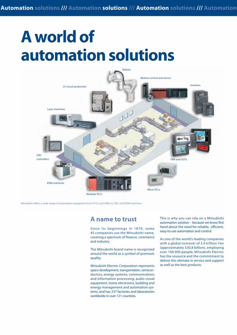
Low Voltage Switchgears /// Moulded-Case Circuit Breakers /// Magnetic Contactors /// Automation solutions /// Automation solutions /// Automation solutions /// Automation
Breakthrough technology
75 years ofexperienceMitsubishi Electric has been active in thelow voltage switchgear (LVS) market since1933. Ever since Mitsubishi developed andmanufactured the first moulded-case circuitbreakers, the company has been committedto research and development in this field,making it one of the world’s leading manu-facturers of circuit breakers.
InnovationGroundbreaking research and design hasresulted in innovative LV switchgear, pro-viding users with greater quality, safetyand reliability. Today’s LV products featuremeticulously designed technology: eventhe casing material is used in the PA (Poly-mer Ablation type Auto-Puffer) to providegreater safety and high voltage breakingperformance.
Meeting globalnorms and standardsMitsubishi Electric’s low voltage switchgearsmeet all the standards and specificationslaid down in the EU Low Voltage Directive73/23/EEC and the Machinery Directive98/37/EC. Needless to say, all the units carrythe CE mark and are certified as conformingto UL, cUL and GOST.
2
Standards are at the center of our productdevelopment.
Mitsubishi offers a wide range of automation equipment from PLCs and HMIs to CNC and EDM machines
A name to trustSince its beginnings in 1870, some45 companies use the Mitsubishi name,covering a spectrum of finance, commerceand industry.
The Mitsubishi brand name is recognizedaround the world as a symbol of premiumquality.
Mitsubishi Electric Corporation representsspace development, transportation, semicon-ductors, energy systems, communicationsand information processing, audio visualequipment, home electronics, building andenergy management and automation sys-tems, and has 237 factories and laboratoriesworldwide in over 121 countries.
Robots
Motion control and servos
Inverters
HMI and GOTs
Micro PLCs
EDM machines
CNCcontrollers
Laser machines
LV circuit protection
Modular PLCs
A world ofautomation solutions
This is why you can rely on a Mitsubishiautomation solution – because we know firsthand about the need for reliable, efficient,easy-to-use automation and control.
As one of the world’s leading companieswith a global turnover of 3.4 trillion Yen(approximately $30.8 billion), employingover 100 000 people, Mitsubishi Electrichas the resource and the commitment todeliver the ultimate in service and supportas well as the best products.
Global Partner. Local Friend.
LVSLow Voltage Switchgears
The complete solutionfor line and load side
SUPER AE Air Circuit Breakers /// WSS Moulded-CaseCircuit Breakers /// MS-N Magnetic Contactors ///Mitsubishi Electric Europe B.V. /// FA - European Business Group /// Gothaer Straße 8 /// D-40880 Ratingen /// Germany
Tel.: +49(0)2102-4860 /// Fax: +49(0)2102-4861120 /// [email protected] /// www.mitsubishi-automation.comSpecifications subject to change /// Art. no. 216798-A /// 12.2008
All trademarks and copyrights acknowledged.
EUROPEAN BRANCHES
GERMANYMITSUBISHI ELECTRIC EUROPE B.V.Gothaer Straße 8D-40880 RatingenPhone: +49 (0)2102 / 486-0
CZECH REP.MITSUBISHI ELECTRIC EUROPE B.V.-org.sl.Radlická 714/113aCZ-158 00 Praha 5Phone: +420 - 251 551 470
FRANCEMITSUBISHI ELECTRIC EUROPE B.V.25, Boulevard des BouvetsF-92741 Nanterre CedexPhone: +33 (0)1 / 55 68 55 68
ITALYMITSUBISHI ELECTRIC EUROPE B.V.Viale Colleoni 7I-20041 Agrate Brianza (MB)Phone: +39 039 / 60 53 1
POLANDMITSUBISHI ELECTRIC EUROPE B.V.Krakowska 50PL-32-083 BalicePhone: +48 (0)12 / 630 47 00
RUSSIAMITSUBISHI ELECTRIC EUROPE B.V.52, bld. 3 Kosmodamianskaya nab 8 floorRU-115054 МoscowPhone: +7 495 721-2070
SPAINMITSUBISHI ELECTRIC EUROPE B.V.Carretera de Rubí 76-80E-08190 Sant Cugat del Vallés (Barcelona)Phone: 902 131121 // +34 935653131
UKMITSUBISHI ELECTRIC EUROPE B.V.Travellers LaneUK-Hatfield, Herts. AL10 8XBPhone: +44 (0)1707 / 27 61 00
EUROPEAN REPRESENTATIVES
BELARUSTECHNIKONOktyabrskaya 19, Off. 705BY-220030 MinskPhone: +375 (0)17 / 210 46 26
BELGIUMKoning & Hartman b.v.Woluwelaan 31BE-1800 VilvoordePhone: +32 (0)2 / 257 02 40
BOSNIA AND HERZEG.INEA RBT d.o.o.Aleja Lipa 56BA-71000 SarajevoPhone: +387 (0)33 / 921 164
CZECH REPUBLICAutoCont CS s.r.o.Technologická 374/6CZ-708 00 Ostrava-PustkovecPhone: +420 595 691 150
CGREECEANTONIOS DREPANIAS S.A.52, Arkadias Str.GR-12132 Peristeri, AthensPhone: +30 210 / 578 1599
GREECEKALAMARAKIS-SAPOUNAS S.A.Ionias & Neromilou Str.GR-13671 Cham. Achames AthensPhone: +30 (0)2102 / 406000
GREECEUTECO5, Mavrogenous Str.GR-18542 PiraeusPhone: +30 211 / 1206 900
HUNGARYMELTRADE Kft.Fertő utca 14.HU-1107 BudapestPhone: +36 (0)1 / 431-9726
KAZAKHSTANTOO KazpromavtomatikaUl. Zhambyla 28KAZ-100017 KaragandaPhone: +7 7212 / 50 10 00
LITHUANIARIFAS UABTinklu g. 29ALT-5300 PanevezysPhone: +370 (0)45 / 582 728
MOLDOVAINTEHSIS SRLbld. Traian 23/1MD-2060 KishinevPhone: +373 (0)22 / 66 4242
NETHERLANDSImtech M & O B.V.Sluisjesdijk 155NL-3087 AG RotterdamPhone: +31 (0)10 / 487 19 11
NORWAYSCANELEC ASLeirvikasen 43BNO-5179 GodvikPhone: +47 (0)55 / 50 60 00
PORTUGALFonseca S.A.R. João Francisco do Casal 87/89PT - 3801-997 Aveiro, EsgueiraPhone: +351 (0)234 / 303 900
ROMANIASirius Trad. & Serv. srlAleea Lacul Morii Nr. 3RO-060841 Bucuresti, Sector 6Phone: +40 (0)21 / 430 40 06
SLOVAKIASIMAP s.r.o.Jána Derku 1671SK-911 01 TrencínPhone: +421 (0)32 743 04 72
SLOVAKIAPROCONT,spol.sr.o.PrešovKúpelná 1/ASK-080 01 PrešovPhone: +421 (0)51 7580 611
SLOVENIAINEA RBT d.o.o.Stegne 11SI-1000 LjubljanaPhone: +386 (0)1 / 513 8116
SWEDENEuro Energy Components ABJärnvägsgatan 36SE-434 24 KungsbackaPhone: +46 (0)300 / 69 00 40
SWITZERLANDTRIELEC AGMühlentalstr. 136CH-8201 SchaffhausenPhone: +41 (0)52 / 632 102 0
TURKEYGTSBayraktar Bulvari Nutuk Sok. No:5TR-34775 Yukarı İSTANBULPhone: +90 (0)216 526 39 90
UKRAINECSC Automation Ltd.4-B, M. Raskovoyi St.UA-02660 KievPhone: +380 (0)44 / 494 33 55
UKRAINESystemgroup2 M. Krivonosa St.UA-03680 KievPhone: +380 (0)44 / 490 92 29
ISRAELGINO Industries Ltd.26, Ophir streetIL-32235 HaifaPhone: +972 (0)4 / 867 06 56
LEBANONCEG INTERNATIONALCebaco Center/Block A Autostrade DORALebanon - BeirutPhone: +961 (0)1 / 240 430
SOUTH AFRICACBI Ltd.Private Bag 2016ZA-1600 IsandoPhone: + 27 (0)11 / 977 0770
Version check


![,;jQkslZ LVs”ku fg.Mu]](https://img.pdfslide.us/doc/110x75/62321adb7760a96b9011f6b5/jqkslz-lvsku-fgmu.jpg)