Embed Size (px)
Citation preview

{' L Summary of ALSEP Subpackage No. 2
Thermal Control Design
RECEIVED
REV. NO.
PAGE OF
JOe pace bptemtl Dlvlelon
7 DATE 6 December 1969
This ATM presents the thermal design, analyses, and testing of the ALSEP Engineering and Prototype Subpackage 2 pallet and the RTG models and includes a summary of Flight transient and steady state temperatures for the Subpackage 2 equipment during ALSEP lunar ~eployment and operation.
Prepared by:
Approved by:

: ; I ~
1 0 0
2.0
3.0
4.0
5.0
Summary of ALSEP Subpackage No. 2 Thermal Control Design
CONTENTS
INTRODUCTION
SUBP ACKAGE NO. 2 DESCRIPTION
THERMAL MODELS AND AN.ALYSES
3.1 STEADY STATE MODEL
3.2 TRANSIENT MODEL
3-3 SUBP ALLET, CABLE REEL AND ALHT CARRIER
3.4 FUEL TRANSFER TOOL
ANALYSIS AND TEST RESULTS
4.1 SUBP ACKAGE NO. 2 TRANSIENT ANALYSIS
4.2 CABLE REEL, UHT, SIDE, EQ.•JIPMENT
4.3 SUBPACKAGE NO. 2 DEPLOYED
4. 3-1 Proto A Thermal Vacuum Test Results
4.4 ASTRONAUT GLOVE TEMPERATURE DU"iUNG TRAVERSE
4.4.1 Maximum Astronaut Contact Times
SUMMARY AND CONCLUSIONS
NO. REV. NO.
ATM-821
PAGE i OF
DATE 6 December 1969
Page
1
1
6
6
10
13
13
17
17
17
23
31
35

Summary of ALSEP Subpackage No. 2 Thermal Control Design
1 oapeoe Syatem8 Dlvlelan
Figure
1
2
3
4
5
6
7
8
9
10
11
12
13
14
15
16
17
19
20
21
LIST OF FIGURES
Title
Lunar Surface Phase
Deployment of ALSEP 1
Stowed Configuration
Subpackage No. 2 Equipment
Barbell Carry
Traverse
Nodal Breakdown of RTG
Nodal Breakdown of Subpackage 2 Pallet
Pallet 2 Deployed
Experiment Mounting Provisions
Transfer Fuel
RTG Fuel Transfer
Fuel Handling Tool Transient Response
Temperature Decay of Fuel Capsule
Flight Subpackage No. 2 Transient Response
D-1A Subpackage No. 2 Transient Response
Flight Model Subpackage No. 2 Transient Response with SIDE and Tool Box Mounted
Flight Model Subpackage No. 2 Transient Response, Cable Spool and Mounting Struts
Subpackage No. 2 Analytical Mode, Deployed Steady State Temperatures
Subpackage No. 2 D-1A Test Results, Deployed Steady State Temperatures
Pallet Assembly No. 2 Proto Test Results, Deployed Steady State Temperatures
NO. REV. NO.
ATM-821
ii PAGE OF
DATE 6 Decembar 1969
2
2
4
4
7
7
8
8
9
14
14
15
16
18
19
20
21
22
24
25
26

' '
: : I ~
'Otlpac&
Summary of ALSEP Subpackage No. 2 Thermal Control Design
~ • .&'telns Division
LIST OF FIGURES (Cont 1 d)
Figure Title
22 Proto A Thermal Vacuum Test Summary - 1
23 Proto A Thermal Vacuum Test Summary - 2
24 Proto A Thermal Vacuum Test Summary - 3
25 Proto A Thermal Vacuum Test Summary- 4
26 Proto A Thermal Vacuum Test Summary - 5
27 Proto A Thermal Vacuum Test Summary - 6
28 Proto A Thermal Vacuum Test Summary - 7
29 Transient Deployment Response, Inner Surface Astronaut Glove, Logarithmic Interpolation
30 Transient Deployment Response, Inner Surface Astronaut Glove, Linear Interpolation
31 Mast/Carry Bar
HO. REV. NO.
ATM-821
PAGE iii OF
DATE 6 December 1969
Page
27
27
28
28
29
29
30
of 32
of 33
34

' l
: : . ~
Table
1
2
3
4
5
Summary of ALSEP Subpackage No. 2 Thermal Control Design
TABLES
Title
Summary of Radiative Properties on Surfaces in Subpackage No. 2 Thermal Model
Subpackage No. 2 Thermal Model Nodes
Thermal Model Resistors
Maximum Astronaut Contact Times
Inner Glove Safe Contact Time
NO. REV. NO.
ATM-821
PAGE iv OF
DATE 6 December 1969
3
5
11-12
36
37

' '
Summary of ALSEP S~bpackage No. 2 Thermal Control Design
NO.
ATl'-:1-821
REV. NO.
PAGE OF
DATE 6 December 1969
1.0 Introduction
This report summarizes the thermal analyses and design of the ALSEP Subpackage No. 2. Results of this ATM are based on the analysis, design, and testing of the Thermal/Mechanical Simulator (D-1A model), the analysis and design of the Prototype A and Flight 1 models, and the thermal testing of the Prototype A model. The thermal analysis of the Engineering D-1A model in the lunar environment, including deployment, is presented as well as the results from the D-1A tests (July 1967) and the Prototype A Thermal Vacuum Tests (December 1967). The thermal analysis of the Flight 1 design, including Subpackage No. 2 equipment, astronaut tools and cable reel, is presented and compared with the D-1A analysis. A thermal analysis of astronaut glove inner surface temperatures is also presented for the time span corresponding to the astronaut traverse to deployment site.
This summary is primarily concerned with the transient phases of the ALSEP deployment during lunar surface operations. The deployment phases include the SNAP-27 fuel capsule transfer, the astronaut traverse to deployment site, and the subsequent removal of the subpackage equipment at the deployment site (see Figure 1). The temperature responses of the deployed ALSEP Pallet ~SNAP-27 RTG as illustrated in Figure 2 also are given.
2.0 Subpackage No. 2 Description
Subpackage No. 2 components and equipment identification along with thermal coatings are listed in Table 1.
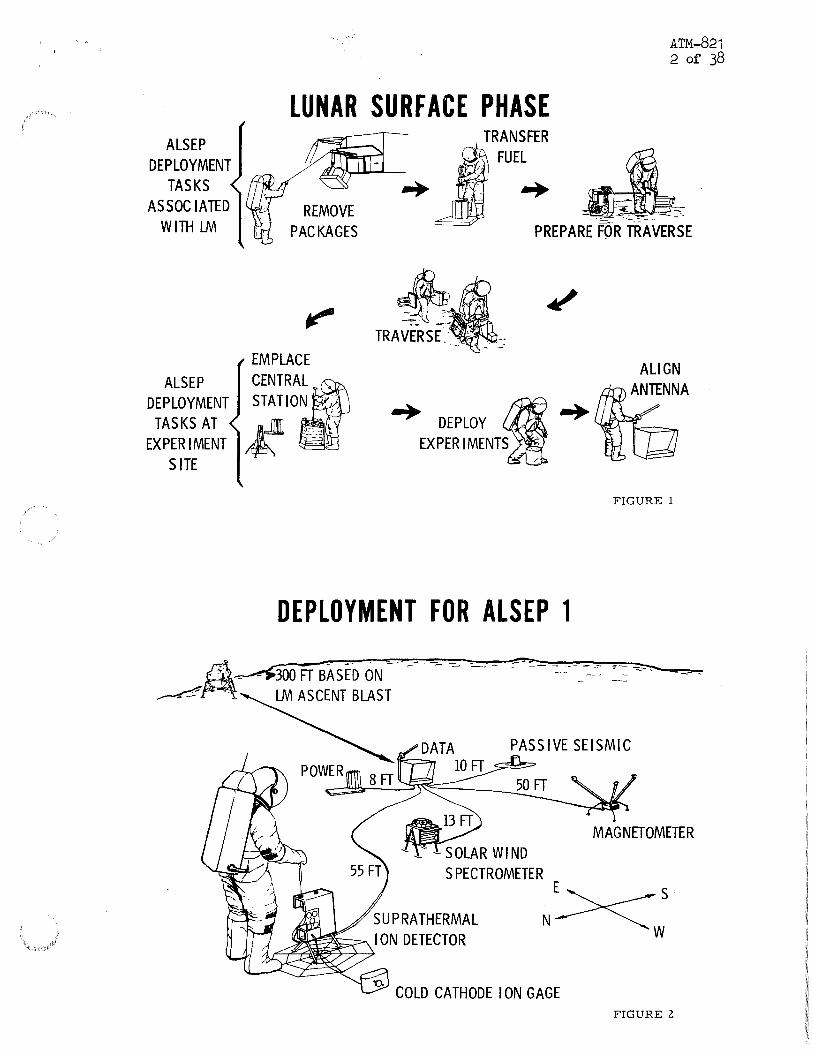
Subpackage No. 2 is shown in Figure 3 in the stowed configuration and consists of the SNAP-27 Generator Assembly, Pallet Assembly No. 2, the Apollo Lunar'Handling Tool Carrier, the Suprathermal Ion Detector Experiment (SIDE) plus additional equipment boxes and astronaut handling tools. The deployed configuration consists of only the RTG mounted on Pallet No. 2. Figure 4 illustrates the deployed configuration plus the position of the subpallet and the ALHT Carrier on the pallet. These latter assemblies are removed prior to completion of deployment with the removal point in the sequence of deployment varying with the deployment mode. The one man deployment concept calls for the removal of these items at the deployment site, while the two man deployment concept calls for the removal prior to fueling the Generator Assembly. The D-1A model utilizes the one may deployment concept, while both concepts have been considered for the Flight and the Proto A models.
Reference to the subpallet assembly in this ATM is defined as the assembly consisting of the SIDE, Antenna Gimbal Box, UHT and the subpallet.
The pallet becomes a base for the deployed Generator Assembly and provides a conductive thermal radiation surface between the Generator Assembly and the lunar surface. The pallet also acts as a thermal shield between the fueled Generator Assembly and the astronaut during the transposition of
' '
ALSEP DEPLOYMENT
TASKS AS SOC lA TED
WITH LM
ALSEP DEPLOYMENT
TASKS AT EXPERIMENT
SITE
LUNAR SURFACE PHASE TRANSFER
FUEL
ATM-821 2 of 38
REMOVE PACKAGES PREPARE FOR TRAVERSE
EMPLACE
CENTRA, STATION ~
~ ~~'
DEPLOYMENT FOR ALSEP 1
FIGURE 1
~~-3o_O_IT_B~AS~E~D~ON~--~-~-~~~~;~~~~-~---~--~-~
~~ LM ASCENT BLAST
~~~~SOLAR WIND SPECTROMETER
MAGNETOMETER
N><s w
-o COLD CATHODE I ON GAGE FIGURE 2

1 .
2.
3.
4.
5·
6.
7·
8.
9·
10.
11.
Summary of ALSEP Subpackage No. 2 Thermal Control Design
TABLE 1
Summary of Radiative Properties of Surfaces Subpackage No. 2 Thermal Models
Surface Description 0( f.
Pallet Assembly No. 2 (top/bottom) .2 ·9
Apollo Lunar Hand Tool (ALHT) . 25 .85
Antenna Gimbal Box . 25 .85
Fuel Cask Handling Tool (FHT) .25 .85
Cask Dome Removal Tool (CDRT) .25 .85
Carry Bars .25 .85
RTG Cable Reel . 25 .85
Universal Handling Tool (UHT) . 25 .85
RTGSurfaces .85 .85
Subpallet .2 ·9
Suprathermal Ion Detector Experiment (SIDE)
.25 .85
NO. REV. NO.
ATM-821
PAGE 3 OF
DATE 6 December 1969
On
Comments
Z~93 White Paint
Sulfuric Anodized
3M401 White Paint
3M401 White Paint
3M401 White Paint
3M401 White Paint
3M401 White Paint
3M401 White Paint
Iron Titinate
3M401 White Paint
S-13G White Paint
ANTENNA
STOWED CONFIGURATION
SUPRA THERMAL ION DETECTOR
ANTENNA
ATM-821 4 of 38
ALHT TOOL CARRIER
AIMING MECHANISM
SOLAR WIND SPECTROMETER
PASSIVE SEISMIC EXPERIMENT
UNIVERSAL HANDLING TOOL
SUPERTHERMAL ~ ~ ION DETECTOR J ~~ ,---------
ANTENNA GIMBAL BOX
1 I I I I I I I I
SUBPALLET
RADIOISOTOPE THERMOE;LECT RIC GENERATOR
PALLET ASSY NO. 2
SUBPACKAGE NO. 2
FIGURE 3
ALHT TOOL CARRIER
FIGURE 4

Summary of ALSEP Subpackage No. 2 Thermal Control Design
NO.
ATM-821
PAGE 5
REV. MO.
OF ospace
Systems Divlelon DATE 6 December 1969
Node Number
1
2
3
4
5
6-7
8-9
10
11
12-13
14-21
22
23
TABLE 2
Thermal Model N·Jdes
Total Thermal Capacitance
Node Description (BTU/°F)
Fuel 0.555
Capsule 0.350
Hot Frame 0.631
Thermopile and Insulation 0.411
Cold Frame 3.003
Outer Shell (symmetric about GA axis) 1.086
Fins (4 fins/node) 1.550
Capsule End Plate 0.151
RTG Bottom Plate (hermetic seal, lower) 0.030
RTG/Pallet Interface (mounting lug and inserts) 0.042
Pallet (4 top and 4 bottom) 0.658
Lunar Surface oo
Space ro

: -: I ;
Summary of ALSEP Subpackage No. 2 Thermal Control Design
NO.
ATM-821
PAGE 6
REV. NO.
OF
DATE 6 December 1969
ALSEP to the deployment site. The RTG is blocked by the other assemblies during this latter phase for the one man deployment concept. No blockage occurs with the two man deployment concept. These are illustrated in Figures 5 and 6.
The fueled SNAP-27 Generator Assembly consists of the fuel capsule assembly, the hot frame, thermopile and insulation, cold frame, outher shell and fins, and the hermetic seal and mounting feet. Basically, the Generator Assembly is a series of concentric cylinders with insulated ends, the inner cylinder being the hot frame. The outer cylinder is the cold frame and outer shell, hereafter referred to simply as the cold frame. Eight radial heat rejection fins are attached to the cold frame. The capsule is the innermost cylinder of the RTG, facing the hot frame. The thermopile (Thermoelectric couple assembly) and insulation occupy the space between the hot frame and the cold frame. The annulus at each end is a hermetic seal, the lower one forming the bottom of the Generator Assembly. The capsule end plate forms the top of the Generator Assembly. The hot frame receives radiant energy directly from the capsule and conducts most of this to the thermopile and insulation. The thermopile converts a portion of this thermal energy into electrical energy. The remaining thermal energy is conducted from the thermopile and insulation layers to the cold frame. The cold frame rejects this heat, plus solar heating, primarily by conduction to the fins and then by radiation to space and the lunar surface.
3.0 Thermal Models and Analyses
3.1 Steady State Model- Nodes
The steady state model for Subpackage 2 consisted of 23 nodes. The nodal arrangement was divided into eight (8) nodes for the pallet, nine (9) nodes for the Generator Assembly, two (2) nodes for the RTG/Pallet interface, and two (2) nodes for the environment. Table 2 lists the number of nodes, node description, and thermal capacitance. Nodes were also assigned for the fuel element and the capsule.
Figures 7 and 8 show the locations of the RTG nodes and the pallet nodes respectively, while Figure 9 illustrates the deployed state.
The steady state analysis assumptions were as follows:
1. RTG surface emittance = 0.85
2. Pallet surfaces coated with thermal control paint having an ex.; f- of • 20/.85
3. No conductive coupling between the pallet and the lunar surface

BARBELL CARRY
• ALLOWS ALL EQUIPMENT TO BE CARR I ED BY ONE MAN IN ONE TRAVERSE
• SUITCASE HANDLES FOR TWO-MAN OR BACKUP CARRY MODE
• Gl VES GOOD BALANCE & VIEW OF FEET
• EQUIVALENT EARTH WEIGHT~ 35 LB
TRAVERSE
A'I'N-821 7 of 38
• MAY BE SET DOWN TO REST
• CARRY BAR LATER USED AS ANTENNA MAST
FIGURE 5
• COMMANDER CARRIES INSTRUMENT SU BPALLET & TOOL CARRIER
• COMMANDER LEADS & PICKS ROUTE
• LM PI LOT CARRIES ALSEP BAR BELL
• REST, AS NECESSARY
FIGURE 6

Figure 7. Na'da1 Breakdown of RTG
RTG CUTAWAY
(1) FUEL---
(3 > HOT FRAME
(2)
ASSEMBLY
(6-7) OUTER CASE (5 > (COLD FRAME)
ASSEMBLY
NOTE: Node numbers in parenthesis
A--- Nodes 12 and 13 on Pallet under RTG
B --- Nodes 14 and 15 near RTG cable reel
C ---Nodes 16 and 17 near crew tools
D --- Nodes 18 and 19 beneath ALHT carrier
E --- Nodes 19 and 21 under SP/2 subpallet
I'
END PLATE (10)
OF FUEL CAPSULE
LUG
THERMOELECTRIC COUPLE ASSEMBLY (
4)
HEAT REJECTION (8-9)
FINS
( 11)
OD
oE
Figure 8. Nodal Breakdown of Subpackage 2 Pallet.
ATM-821 8 of 38

Outer Shell & Cold Frame Ass 1y.
~----"'-,
RTG/PAL Interface
" '
Figure 9.
Capsule End Plate
Pallet Under RTG
Outer Pallet
Pallet 2 Deployed
'-Oll>
o:£ 1-1)~ w 1\) CD-"

: : I •
if
1 oapace
Summary of ALSEP Subpackage No. 2 Thermal Control Design
NO. REV. HO.
ATM-821
PAGE 10 OF
Systems Dlvlelon DATE 6 December 1969
4. All boxes and equipment, except RTG, removed.
5. RTG axis perpendicular to the lunar surface.
3.2 Transient Thermal Models - Nodes
The transient thermal models of D-1A and the Flight (one man), with Subpallet Assembly and the Apollo Lunar Hand Tool (ALHT) Carrier mounted, consisted of the steady state nodes plus 6 nodes for each equipment box and/or experiment. The 6 nodes correspond to the 6 sides of each box or experiment. The Flight (two man) transient model was the same configuration as the steady state model. Figure 5 shows the one man deployment concept and Figure 6 illustrates the two man deployment.
All transient analyses assumed the following:
1. Surface emissivities and solar absorptivities per the steady state model.
2. No conductive coupling between the pallet and the lunar surface.
3. Surface of boxes facing RTG, ~ = 0.1 for D-1A, and E = 0.85 for Flight model (one man).
4. Box/equipment surfaces not facing RTG coated with a white thermal coating with an()(/~= .25/.85.
5. RTG axis parallel to lunar surface.
6. Corner of pallet closest to RTG oriented closest to lunar surface.
7. Bottom of the Subpackage No. 2 pallet radiating to a lunar surface temperature of 100°F.
8. Initial SP2 temperature at 160°F, except capsule assembly.
9. Capsule assembly at lunar landing temperatures.
Conduction resistors were calculated from configuration geometry and the material thermal conductivities. Thermal capacitances were calculated from material properties and nodal weights. Radiation resistors were derived from a Gebhart Absorption analysis wherein perfectly diffuse surfaces were assumed. Configuration factors for the Absorption program were derived with the BxA Confac II program. Surface areas were obtained from the configuration geometry, and emissivities were obtained from the particular surface properties. Solar heating was calculated for each surface, taking into account solar absorptivity, solar angle, shadowing and reflection from

Summary of ALSEP Subpackage No. 2 Thermal Control Design
TABLE 3
NO. REV. NO.
ATM-821
PAGE 11 OF
DATE 6 December 1969
Pallet 2 Steady State Thermal Model Resistors
Conduction Resistors
Node to Node
1 - 2 1 - 3 1 - 9 1 - 17 1 - 22 2- 4 2 - 9 2 - 17 2 - 23 5 - 6 5 - 20 5- 22 5 - 7 5 - 8 6 - 21 6 - 23 7 - 8 7 - 18 8 - 19
18 - 19 18 - 20 19 - 20 21 - 20 9 - 13 1 - 12 2 - 12
12 - 14 9 - 16
13 - 16 14 - 15 16 - 17
Radiation Resistors
Node to Node
1 - 3 1 - 4 1 - 5 1 - 7
R, hr-F/Btu
0.564 0.077
23.64 0.0018 1.47 0.077
23.64 0.0018 1.47 1.52 0.0266 0.865 3.16 2.70 0.0266 0.830
10.24 0.0196 0.0233
10.24 3.16 2.67 1.52
114.0 3.0 3.0 3.96
28.15 0.0614 0.067 0.0614
a"~ A Btu/hr 0 R4
o . 3242 x 1 o-9 0.3529 x 1o-11 0.2837 X 10⁻⁹
0 0.2393 X 10⁻¹
Comments
Outer shell facing experiments to connecting nodes.
1 Outer shell away from experiments to connecting nodes.
t Pallet under RTG facing experiments to connectin~ nodes.
i Pallet under RTG away from experiments to connecting nodes. Outer pallet under SIDE to connecting nodes. Outer Pallet under ALHT to Bottom Pallet bottom to connectin nodes.
RTG bottom to Hot Frame. Outer shell to capsule and plate.
Capsule end plate to capsule. RTG bottom to Thermopile and insulation. Hot frame to Thermopile and insulation. Capsule to Fuel. Thermopile and insulation to Cold Frame.
Comments
Outer shell facing experiments to fins, pallet RTG, lunar surface and space.*

S~ary of ALSEP Subpackage No. 2 Thermal Control Design
TABLE 3 (Cont'd)
MO. REV. MO.
ATM-821
PAGE 12 OF 38
DATE 6 December 1969
Pallet 2 Steady State Thermal Model Resistors
Radiation Resistors
Node to Node
1 - 8 1 - 9 1 - 10 1 - 11 2 - 3 2 - 4 2 - 6 2 - 9 2 - 10 2 - 11 3 - 4 3 - 5 3 - 6 3 - 7 3 - 8 3 - 9 3 - 10 3 - 11 4 - 5 4 - 6 4 - 7 4- 8 4 - 9 4 - 10 4 - 11 5 - 6 5 - 7 5 - 8 5 - 9 ) - 10 5 - 11 6 - 9 6 - 10 6 - 11 7 - 10 7- 11 8 - 10 8 - 11 9 - 11
12 - 11
(f" tq. A Btu/hr 0R4
0.1483 X 10⁻¹⁰ 0.4077 X 10⁻¹¹ 0.2731 X 10⁻⁹ 0.6539 X 10⁻⁹ o. 3525 x 1 o-11 0.3238 X 10⁻⁹ 0 • 2837 X 10-9 0 • 4077 X 10-11 0.2956 X 10⁻⁹ 0.6705 X 10⁻⁹ 0.4430 X 10⁻⁹ 0.3268 X 10⁻⁹ 0.3899 X 10⁻¹¹ 0.8169 x 1o-10 o. 114 3 x 1 o-9 o.4748 x 1o-11 0.1594 X 10⁻⁸
8 0.2459 X 10-0.3899 X 10⁻¹¹ 0.3268 X 10⁻⁹ 0.8863 X 10⁻¹ 2 o • 1240 x 1 o-11 0.4747 X 10-
811
0.1765 X 10-0 • 2594 x 1 o-8 0.8572 x 1o-11 0.1359 x 1o-11 0.1335 x 1o-11 0.1134 X 10⁻⁹ 0.2064 x 1o-10 0.6069 X 10⁻⁹ 0.1134 X 10⁻⁹ 0.2264 x 1o-10 0.6084 X 10⁻⁹ 0 • 1739 X 10-
811
0.2094 X 10-0.1888 X 10⁻¹¹ 0.1082 X 10⁻⁸ 0.1739 x 1o-1o 0.2940 X 10⁻⁹
Comments
Outer shell facing experiments to fins, pallet RTG, lunar surface and space. i~
t . Outer shell away from experlments to fins, pallet, RTG lunar surface, and space.*
1 Fins facing experiments to fins, pallet, RTG, lunar surface, and space.*
l Fins from experiments to fins, pallet, RTG, lunar surface, and space.
l Pallet under RTG facing experiments to pallet, RTG, lunar s;ll'face, and space.*
! Pallet under RTG away from experiments to RTG, lunar surface, and space.*
Outer pallet under SIDE to lunar surface and space.* Outer pallet under ALHT to lunar surface and space.* RTG bottom to space.* Capsule end plate to space.*
i~Evaluated using Gebhart absorption factor technique

Summary of ALSEP Subpackage No. 2 Thermal Control Design
NO.
ATM-821
PAGE 13
REV. NO.
OF ,epace
Systems Division DATE 6 December 1969
other surfaces. Contact conductance was estimated as 50.0 Btu/hr ft2 F for high contact interfaces, 5.0 Btu/hr ft2 F for medium contact interfaces, and 1.0 Btu/hr ft2 F for loose contact interfaces. Nodes were connected with the applicable resistors, listed in Table 3, and assigned thermal capacitance v~lues, initial temperatures and heat loads corresponding to each case under study. The Bendix Thermal Analyzer Program was utilized on the IBM 360 Computer to solve for both transient and steady state temperatures.
3.3 Sub-Pallet, Cable Reel and ALHT Carrier
The sub-pallet and ALHT Carrier were analyzed concurrently with the Pallet Assembly No. 2. Emissivity of the sub-pallet was assumed to be 0.85 for all surfaces, while the ALHT Carrier was analyzed for both 0.1 and 0.85 emissivities for the surface facing the RTG. The remaining surfaces of the ALHT Carrier were assumed to have an emissivity of 0.85.
The cable reel was analyzed as two nodes, the spool and the mounting struts. Emissivity was assumed to be 0.85 for all surfaces. No conduction to the pallet, cable, or between the mounting struts and the spool was assumed.
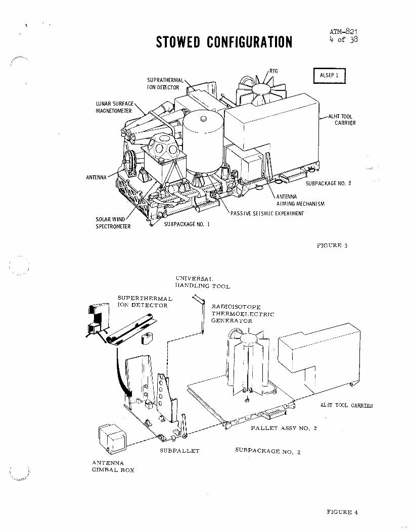
Figure 10 illustrates areas where the Universal Handling Tool (UHT) will be used. This tool will have approximately the same transient response as the cable reel if the sub-pallet is mounted on the Subpackage 2 during traverse.
3.4 Fuel Transfer Tool
The FTT was analyzed as 4 nodes with a constant temperature source node. The four nodes were:
1. Disc facing source
2. Fingers contacting source
3. Handle attach adapter for 1 and 2 above
4. Handle (center of node at handle C.G.)
Heat transfer is by radiation from the source to the disc, conduction from the source to the fingers, conduction from the disc and fingers to the attach adapter, and conduction from the adapter to the handle. Radiation to the environment and solar heating were not considered for this analysis in order to study worst case conditions. See Figures 11 and 12 for a summary of the fuel transfer task.
Figure 13 presents the results of a transient analysis on the Fuel Transfer Tool. The heat source was the Capsule End Plate at a constant
EXPERIMENT MOUNTING PROVISIONS ATM-821 14 of 38
LSM
TRANSFER FUEL • PREPARE CASK
RETRIEVE LOCK-PIN LANYARD, PULL PIN, RETRIEVE CASK-TILT LANYARD, ROTATE CASK TO DES IRED ANGLE, REMOVE DOME
• PREPARE SUBPACKAGE 2
RETRIEVE MAST SECTIONS & TOOLS, PLACE IN NEW LOCATIONS, ROTATE SUBPACKAGE TO TRANSFER POSITION, PREPARE FUEL TRANSFER ASSEMBLY TOOL
• FUEL RTG .
ENGAGE TOOL WITH CAPSULE, LOCK TOOL I
FIGURE 10
CAPSULE TO RELEASE FROM CASK, WITHDRAW !"""'-------("
CAPSULE, CARRY TO RTG, RELEASE TOOL I CAPSULE TO LOCK IN RTG
FIGURE 11

--' ... =
......
ATM-821
15 o
f 38
N
.......

~ o·
400
350
300
250
~ ~ ;:J ~
< ~ ~ 200 11. ~ ~
~
150
100
FUEL TRANSFER TOOL TRANSIENT RESPONSE INITIAL CONDITIONS: LUNAR LANDING TEMPERATURE CAPSULE END PLATE AT 800°F
DISC
HANDLE C.G.
~---------------------------------------------------------------------------------------------~~
0 2 4 6 8 10 12 14 16 18 20
ELAPSED TIME FROM CONTACT WITH CAPSULE END- MINUTES
FIGURE 13
0'\~
~~ 1\)
w -I. (X)

Summary of ALSEP Subpackage No. 2 Thermal Control Design
NO.
ATM-821
PAGE 17
REV. NO.
OF
DATE 6 December 1969
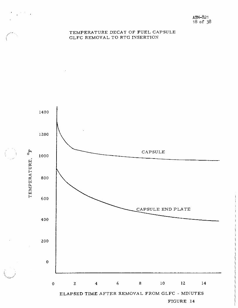
temperature of 800° F. Surface emissivity of the disc was assumed to be 0.25. Radiation to other surfaces of the FTT was assumed negligible. The disc exceeded 250° F within 2 minutes after ccntact of FTT with the Capsule End Plate. The remainder of that end of the FTT exceeded 250° F within 9 minutes. Temperature rise at the handle C.G. was approximately 2° F during the first 10 minutes.
Figure 14 shows the temperature decay of the capsule and end plate between removal from the GLFC and RTG insertion. The decay is very high for the first few minutes after removal. Thus the temperatures, beyond the first 2 minutes, shown in Figure 13, are conservative.
The surface of the disc may have a high emissivity, in which case FTT temperatures will be considerably higher. However, present FTT contact time with the capsule end is approximately one minute. An analysis of the FTT, with t= 0.9 for the disc, resulted in a disc temperature of 250° F with the remainder of the FTT below 200° F for one minute contact time.
4.0 Analysis and Test Results
4.1 Subpackage No. 2 Transient Analyses
Figures 15 through 17 present time-temperature predictions for Subpackage 2 during traverse to the deployment site. Figure 15 is the transient analysis for the Flight (two man) model. The others are models with boxes and/or equipment mounted during traverse. RTG temperatures are approximately the same for all three cases. Pallet surfaces under the RTG are considerably cooler for the Flight (two man) model than for the other two cases. Cold frame temperatures exceed 250° F within 12 minutes from time of fueling, and all external RTG temperatures exceed 250° F within 25 minutes. Maximum pallet temperatures exceed 250° F in 40 to 50 minutes from fueling, depending on the model.
Test results indicate thermocouple location temperatures, while analytical temperatures are average nodal temperatures. Thus analytical results indicate approximately the average temperatures under the RTG and for the remainder of the pallet.
4.2 Cable Reel and Equipment
Figure 18 presents the results of a transient analysis on the Cable Reel during traverse. The mounting struts exceed 250° F in apgroximately 30 minutes after RTG fueling while the cable spool exceeds 250 F in approximately 50 minutes. Temperatures in the deployed mode will be less than for the traverse, but the time to reach 250° F during the deployment mode will be no more than 5 minutes greater than for traverse.
1400
1200
~ 0
1000 ~
r:il ~ p E-< ~
800 ~ r:il p. ::;E r:il E-< 600
400
200
0
0
TEMPERATURE DECAY OF FUEL CAPSULE GLFC REMOVAL TO RTG INSERTION
CAPSULE
2 4 6 8 10 12
ATM-821 18 of 38
14
ELAPSED TIME AFTER REMOVAL FROM GLFC - MINUTES
FIGURE T4

700
600
500 I \
I ' ~ 400 0 I
~
~ ~ 0
300 I ~ <r: ~ ~ I ~ ~ ~ 200 ~
L .. ~
l~ 100
0 0
/
__...,-
10
FLIGi .AODEL
SUB-PACKAGE NO. 2 TRANSIENT RESPONSE RTG FUELING TO DEPLOYMENT SITE INITIAL CONDITIONS- LUNAR LANDING TEMPERATURES 20° SOLAR ANGLE TO RTG & PALLET
CAHSULE·END.PLATE
COLD FRAME ~ ~
~ FINS
/ ------------- ----PAL/RT_G... INTERFACE
~ -------- ------ PALLET .UNDER FINS
~----- ~ OUTER PALLE'T'
20 30 40 50 60
ELAPSED TIME - MINUTES CAPSULE INSERTED AT TIME= 0
FIGURE 15
-":t> '-0 1-3
~t 1\)
w--" CX>

700
600
500 \ ~ 0
~
I ril 400 P:: p ~ <X; P:: ril 300 ~ ~ ril ~
200 I _/"'
100
0
0
"-....
~~
10
D-lA MODEL (REFLECTIVE BOXES)
SUB-PACKAGE NO. 2 TRANSIENT RESPONSE RTG FUELING TO DEPLOYMENT SITE INITIAL CONDITIONS- LUNAR LANDING TEMPERATURES 20° SOLAR ANGLE TO RTG & PALLET
CAPSULE END PLATE
------ ----- FINS
~-------
20 30 40 50
OUTER PALLET & BOXES (MAX)
60 I\) :X:. 05e 0 I
ELAPSED TIME - MINUTES - CAPSULE INSERTED AT TIME= 0 H) (X)
[\) LV-' co
FIGURE 16

~ 0
~
~ ~ ::> E--1 ~ ~ IZl ~ ~ ~ E--1
700
600
500
\ 400
I
300
200 I
100
0
0 10
FLIGHT MODEL WITH SIDE & TOOL BOX MOUNTED (BOTH NON -REFLECTIVE) SUB-PACKAGE NO. 2 TRANSIENT RESPONSE RTG FUELING TO DEPLOYMENT SITE INITIAL CONDITIONS - LUNAR LANDING TEMPERATURES 20° SOLAR ANGLE TO RTG & PALLET
CAPSULE END PLATE
----- COLD FRAME
_.,.---- FINS
PALLET UNDER FINS
>:c EQUIPMENT ANDTOOL BOX {MAX)
OUTER PALLET
20 30 40 50 60
ELAPSED TIME -MINUTES- CAPSULE INSERTED AT TIME= 0
1\);:t> ~1-3
~
~&, f\)
w~ co
>:c Equipment consists of SIDE, PSE Mount, Antenna Gimbal and Experiment Handling Tool FIGURE ~i7

~ 0
~
~ p::; ::> E-l <t: p::; !:il Po. ~ !:il E-l
350
300
250
200
150
100
0 10 20
FLIGHT MODEL
SUB-PACKAGE NO. 2 TRANSIENT RESPONSE CABLE TEMPERATURES DURING TRANSPORT TO DEPLOYMENT SITE INITIAL CONDITIONS - LUNAR LANDING TEMPERATURES 20° SOLAR ANGLE TO RTG AND PALLET
MOUNTING STRUTS
30 40 50 60
ELAPSED TIME -MINUTES - CAPSULE INSERTED AT TIME== 0 FIGURE 18
1\)~
1\)~ 0 I ~CP
1\) \..A.J __,. CP

: : . . Summary of ALSEP Subpackage No. 2
Thermal Control Design
NO.
ATM-821
PAGE 23
REV. NO.
OF
DATE 6 December 1969
Maximum traverse temperatures of the SIDE, Antenna Gimbal, UHT, and the non-reflective ALHT Carrier mounted to the Pallet Assembly No. 2 are shown in Figure 17. Traverse temperatures for reflective boxes mounted to Pallet Assembly No. 2 are shown in Figure 16. None of the temperatures exceed 200° F within 45 minutes after RTG fueling. UHT temperatures for the one man deployment may be taken from Figure 18.
The above parts are coated with thermal paint having a low 0(/~ ratio (.20/.85). Therefore, the temperatures will not exceed 250° F when the parts are removed from the fueled Subpackage No. 2. The equilibrium temperature for an Q(/€ = .20/.85 vertical surface with a solar angle of 40° is 140° F.
4.3 Subpackage No. 2 -- Deployed
Figures 19 through 28 present the Subpackage No. 2 temperature profiles during Lunation. Figure 19 temperatures represent the analytical model, and others show D-1A and Proto Thermal Vacuum Test Results. The o~ mode of heat transfer assumed to exist between the bottom surface of the pallet and the lunar surface was radiation for all three cases. Analysis and test results showed that the RTG temperature changes are primarily a function of solar heating, being only slightly affected by pallet temperature changes. Analysis has shown a RTG temperature drop of 5° F for lunar noon and a drop of 14° F for lunar night resulting from the addition of high coupling between the bottom surface of the pallet and the lunar surface. The pallet temperatures follow the lunar surface temperature more closely for the latter case than for the analytical case shown.
Pallet and RTG maximum temperatures are:
Component Lunar Noon, OF Lunar Night, OF
Capsule 1380 1350
Hot Frame 1100 1050
Cold Frame 480 440
Pallet under RTG 425 250
The pallet is nearly isothermal from the top surface to the bottom surface, and isothermal planes are approximately concentric with the longitudinal axis of the RTG.

1400
1200
1000
800
·~ 0 600
~ ex; ::> E-i <t: 400 ex; ~ ~ ~ ~ E-i 200
0
-300
SUB-PACKAGE NO. 2 ANALYTICAL MODEL DEPLOYED STEADY STATE TEMPERATURES ONE LUNATION PERIOD
LUNAR SURFACE----u
CAPSULE
HOT FRAME
THERMO PILE
CAPSULE END PLATE
OUTER SHELL NS
O'UTER PALLET
ATM-821 24 of 38
NIGHT 0 30 60 90 120 150 180
SOLAR ANGLE - DEGREES FROM SUNRISE
FIGURE )9

1400
1200
1000
800 ~
0
t:il tx: :;:J
600
E-4 <!:; tx: t:il 0;
400 ~ t:il E-4
200
0
-300
SUB-PACKAGE NO. 2 - D-1A TEST RESULTS DEPLOYED STEADY STATE TEMPERATURES
HOT FRAME
ROOT OF FINS
PALLET UNDER FINS
OUTER PALLET
LUNAR SURFACE
NIGHT 0 30 60 90 120 150
SOLAR ANGLE - DEGREES FROM SUNRISE
180
ATM-821 25 of 38
FIGURE 2.()

PALLET ASSEMBLY NO. 2 -PROTO TEST RESULTS DEPLOYED STEADY STATE TEMPERATURES: °F UPPER TEMPERATURE AT EACH POINT IS LUNAR NOON LOWER TEMPERATURE IS LUNAR NIGHT
226 s -18
238 s 2
227 s 8
214 s -14
BOTTOM SIDE
s 323 151
325 s 150
S329 '141
s 333 182
366 328 s
19, 190
s 333 170
TOP SIDE
s 248 42
s 325 137
s 337 177
6) 240 48
ATM-821 26 of 38
FIGURE 21

0 0
0 "'
0 0
0 ::r
0 oo .--.a
""' LLa -a
0 N
w a: ::::> t-o a:: a a: w~ CL L. w r-
0 0
FIGURE 22
BENDIX RER~SPRCE SYSTEMS DIVISI~N
ATM-821 27 of 38
PR~GRRM RLSEP TEST N~. S1 TEST ORTE 12/15/67 ZER~ TIME 000000 TEST TITLE PR~T~ R SYSTEM THERMAL VRCUUM TEST SUMMARY
~ 102 PAL 2 1CP SURFACE UNDER R1G ~ 104 PAL 4 1CP SURFACE UNDER R1G
i i
~ !03 PAL 3 1CP SURFACE UNDER R1G ~!OS PAL 5 TCP SURFACE UNDER RTG
-------+-----+-+---------------l----1~--e----- j----- -----l----- -----
---+----+-1--fV---------1------~ _j_ ___ -------++--1~ -+----+-----1 ' ~ I ~
II '-----
0
0 0
0 ~
0 0
0 ::r
0 0
0 ("")
- 0 oo .--<0 ¥N
U....o -a
0
w a: ::::> tO:: a a: a
~0 L. w r-o
0
0 ~
I
0 0
0 N
10. O')
10. oo
~I !
I I
i I I 24.00 48.00 qn_oo 12o.oo 144.oo 168.00 19~.00 216.00 240.0
T I 1"1E (H~URSJ
FIGURE 23
BENDIX RER~SPRCE SYSTEMS DIVISI~N PR~GRRM RLSEP TEST N~. 51 TEST ORTE 12/15/67 ZERD TIME 000000 TEST TITLE PR~T~ R SYSTEM THERMRL VRCUUM TEST SUMMRRY
~ 101 PAL 1 TCP SURFACE UNDER RTG ~ l 06 PAL 6 TOP SURFACE. RIGHT FRCNT --l ~ 107 PAL 7 TOP S U f!,(R C£ . .L E F 1fTiltrr.J T <!> 108 PAL 8 TOP SURFACE. LEFT REAR
( J
~-----
- .F ~ I ,l$l._ ~ 'j( -- ~ I
.I
~1 fJ I -~ I
I~ ----~--
ft -·- --- --
IGN I }. ~
~
1,;:::! N
~If ~
r- LUNAR----1 t---LU1 AR---1 NOON Nl( HT
t; 24.00 48.00 72.00 95.00 LGG.Qn 144.00
T I ME UiCT\.J'R.5Jl 168.00 192.00 216.00 240.C

FIGURE .24
BENDIX REROSPRCE SYSTEMS DIVISION
ATM-821 28 of 38
PROGRAM RLSEP TEST NO. S1 TEST DRTE 12/15/67 ZERO TIME 000000 g TEST TITLE PROTO A SYSTEM THERMAL VACUUM TEST SUMMARY ~~-------------------------------------------------------------------------------
0 0
~ 109 PAL 9 BOTTOM SlOE UNDER PAL 2 ~Ill PAL 11 BOTTOM SlOE UNDER PAL 4
~ 110 PAL 10 BOTTOM SlOE UNDER PAL 3 ~ 112 PAL 12 BOTTOM SlOE UNDER PAL 5 l
~+-------,--------,-------,-------,·-------·-T-------,--------r-------,--------,-------~
~~ l ____ _j_ __ ___jl___--J~~~=!!.F* ----~~~ f -1
----t----t----P---J-+-----· __ J I
i
I . . -+ -- ~--·- . LL.o -a
0 1--· N w
·--- ------ ------j
a: :::::J t-o a:,p a: I w<;:
I
+--------t----------+-1\1-----+--- --- . - r----- ... -------+-----+----t-- ·- --·-
I 0... .L ! :
w t-
0 I 0
0 f------ -+ --- ·--~------+------1------ -
1
fLUNAR_,j j II ,,OON I I --1--- --- ---- -- - :. - - - t--
0 0
0 -
I
I I l ~ I .
~ i I
1
I
I 'o. DO 24.00 48.00 72.00 96.0r:J 120.10 14'-!.00 168.00 1!'12.00 216.00 240.C
TIME (HOiJ,-'1::.,)
FIGURE 2S
BENDIX AEROSPACE SYSTEMS DIVISION 0 0
PROGRAM RLSEP TEST NO. S1 TEST DATE 12/15/67 ZERO TIME 000000 TEST TITLE PROTO R SYSTEM THERMAL VRCUUM TEST SUMMARY
~-.-------------------------------------------- ------------------------------
0 0
~ 113 PAL 13 BOTTOM SlOE UNDER PAL 6 ~ 115 PAL IS BOTTOM SlOE UNDER PAL 8
g+-------,---~---.------,--------.--
- 0 ~ oo ~ ;~+-------~-------+-----.B~~~e-~J~~~---
LL.o -o
~ 114 PAL 14 BOTTOM SlOE UNDER PAL 7
~ ~+-------t-------+--~~f,--'1-- 1------ . -t----t----t---- ~ --+ --+---- - -·-----'
~o ~ I '-"'- ·~ -,_ /
a:o f!. A ~o+--------t-----+---H.~-----+---------~~4•'----=:~~~~?j[-·------t--------j-------t--------
~-o ~ LUNAR J : I-= LUiJAR (I 0 NOON~ ! t---NICI-JT~ ' 0 i -;--t-------~-----JI:---t--------+-------1------- t----- ---- ---r--·----t------t------1

ATM-821 29 of 38
0 0
0 lfJ
0 0
lfJ N
0 - 0 0 ~0
0
"'-
0 0
FIGURE 26
BENDIX REROSPRCE SYSTEMS DIVISION PROGRRM RLSEP TEST NO. Sl TEST DRTE 12/IS/67 ZERO TIME 000000 TEST TITLE PROTO R SYSTEM THERMRL VRCUUM TEST SUMMRRY
[!! 88 RTG I HIH FRAME. F]N 5 (T) 89 RTG 3 HIH FRAME. FJN 7-fJN 8 I
<!I 90 RTG 4 Hl'll FRAME. FJN 5 <!> 91 RTG 5 Hl'll FRAME. FJN 2-FJN 3
I
J...\ _11 ·-a~-,=Y I .,-4:h Pl ,.-/"= -= \\_ --- -----
I I
I I I
-~--r--I I
--- ~---- -- -i---------j--------------
I i I I
"'"R~T~,t~ --- ·-~- - ----1----- '----·-
~ I
-<?"d I
NOON ,H~ T
lk. r- --. ------r --f ,. ----
,Jl -- -- ·----~~ ----- ' ·-- ----- ---
~ I I
I I I
"b. 00 24.00 48.00 72.00 95.00 120.00 144.00 !68.00 192.00 216.00 240 .r T; :-~>:: (1-if'J'mJJ
FIGURE 2.7
BENDIX AEROSPACE SYSTEM~ JIVISION PROGRAM RLSEP TEST NO. Sl TEST DATE 12/15/67 ZERO TIME OOOOOQ
0 0 TEST TITLE PROTO R SYSTEM THERMRL VACUUM TEST SUMMARY ~.--------------------- ------------------- --·
FJN I. Tl'lP SLI'll 93 RTG 9 FJN
0 0
[!!
<!I
0+------~
- 0 oo
92 94
RTG 7 RTG 10 FJN 5. Tl'lP
r:-w
(T)
SLI'll <!> 95 RTG 11 FJN ~
~ 1 -- - ---
I I
1. Bl'l111'lM SLI'll
5. MJODLE SLIH
! I
----------1
';g+-----+--------+---+--+----+-1--11 --- ----+----T+-----+------
LLo
-o I : w a:
~-~------+------+-+---+----~------- -- _____ , ___ _
, i I
t---------: ------ f--- --1
I I
~g I : i ~~-~------+------+--!---+----+--------- -+1-1\.r--------+-------j------+------l
:w :+------+---l~~~~~---f--1--L-::_t_:_-1 __ ~ ;:: ~~_-_j - ------1-----1---------1
:~~~~--~~~-~~, ~--~~~ 'o.oo 24.00 48.00 n.oo 95.oo 120.00 144.00 168.oo 192.00 2t6.oo 240.0
TIME (HOURSJ

0 0
0 lf)
0 0 . 0 ~
..... 0 oo .--<0 :;j(('f')
LLo ~a
0 ('\J
w a:
.::J
t-o O:o a: . w~ Q_
FIGURE 28
BENDIX AER~SPACE SYSTEMS DIVISI~N PR~GRAM ALSEP TEST N~. S1 TEST DATE 12/15/67 ZER~ TIME 000000 TEST TITLE PR~T~ A SYSTEM THERMAL VACUUM TEST SUMMARY
[!] 96 R1G 13 ~U1ER SHELL FIN PER C9 97 RTG 14 ~UTER SHELL FIN 2-FIN 3
~ 98 R1G 15 ~UTER "'O[lC.T...L T ll'l 8. Lei .-lEA ~ 99 R1G 16 Pe!WER HERDER TEMP
~ "' "' m 5 l\ (
(r ~ ..... £ ~ ~
"' "' ~ ~ ~ ~
~ ... .&
~ ~ ~ ~ ~ ~
------
- - - 0 .L w t-
- - -- ' \.
0 0
0
0 0
0 .- L_
'o. oo
l~ f ~
--------
24. o-o-----~
~ I-LUNAR~ NOON ~LUN
NIG ~--4
l l 72.00- 96.00 120.00 144.00 168.00 192.00 216.00
TIME (H~URSJ
I
I
LU:t> 0:£ OJ ~())
1\) LV--'-())
240.(

: ; . . Summary of ALSEP Subpackage No. 2
Thermal Control Design
NO.
ATM-821
PAGE 31
REV. MO.
OF 38
. . roapace Systems Dlvllllon DATE 6 December 1969
The temperature results of the Proto A Thermal Vacuum Test for the integrated SNAP-27 RTG/Pallet 2 configuration were near nominal. Generator steady state hot and cold frame maximum temperatures were 1190° F and 440° F for lunar day operation and 1145° F and 380° F for lunar night at an alectric fuel capsule setting of 1400 watts. Pallet 2 equilibrium surface temperatures ranged from 225 to 375° F during lunar noon to -35 to 180° F for lunar night.
Figures 21 through 28 illustrate the temperature distribution on Subpackage No. 2 for Proto A. The temperature of the Pallet 2 surface below the RTG ranged from a maximum of 375° F during lunar noon to 177° F during lunar night compared to predicted temperature limits of 394° F and 187° F, respectively. Lunar morning, noon, and night are indicated in Figure 22. The differences between pretest predictions and the Prototype test results are attributed to the lower RTG power setting of 1400 watts instead of the 1500 watt RTG dissipation used in the analysis.
Near the end of the lunar night, the RTG power was increased to 1500 watts. The average hot and cold frame temperatures reached 1109° F and 392° F, respectively. This increase in power caused an increase in temperature across Subpackage 2 and is shown in the temperature plots at the end of lunar night.
4 .• 4 Astronaut Glove Temperature During Traverse
Figures 29 and 30 present analytical temperature responses for the inner surface of the astronaut glove during traverse. The thermal properties of the glove were derived by interpolation of test data presented in the reference. This reference is an MSC report on tests to determine the temperature rise of the inner surfaces of the astronaut suit and glove. Tests were conducted with the outer glove surface in contact with various constant temperature sources.
0 No data were presented for source temperatures below 250 F. The data were presented in the form of inner surface temperature vs. time, for constant source temperatures. The slopes of these curves are then temperature rise per unit time.
The slope of the time temperature curve was assumed zero at 70° F. The temperatures shown in Figura 29 are the result of logarithmic interpolation of the slopes from test data. Figure 30 presents the glove inner surface temperatures with linear interpolation of the slopes from the test data. The source temperatures used for both cases were the transient temperatures of the pallet surface under the RTG for Flight (two man) configuration. The source temperature will be somewhat lower due to the thermal resistance between the pallet and the astronaut contact area on the carry bar (see Figure 31). Since linear interpolation of the slopes is worst case this will be assumed pending information as to the thermal properties of the glove at temperatures other than those presented in the reference.

140
130
P-i 0
fil 120 ~
~ < Jt: fil 110 ~ ~ fil f-i
fil > 100 0 ....:l a p::; fil z 90 z 1-1
80
70
0 10
TRANSIENT DEPLOYMENT RESPONSE INNER SURFACE OF ASTRONAUT GLOVE THERMAL RESISTANCE OF GLOVE OBTAINED BY LOGARITHMIC INTERPOLATION OF MSC TEST DATA
20 30 40 50 60 70 80 90 100
ELAPSED TIME FROM RTG FUELING - MINUTES
FIGURE 29
w:x> [\):£ o I ~co
[\) VJ-" co

140
130
0~ 120
~-
~ ::J ~
-< ~ 110 ~ ~ ~ ~ ~
~ 100
:> 0 ~ ()
~ ~ 90 z z H
80
70
0 10
TRANSIENT DEPLOYMENT RESPONSE INNER SURFACE OF ASTRONAUT GLOVE THERMAL RESISTANCE OF GLOVE OBTAINED BY LINEAR INTERPOLATION OF MSC TEST DATA
20 30 40 50 60 70 80
ELAPSED TIME FROM RTG FUELING - MINUTES
90 100
FIGURE 30
LU::t> LU~ 0 I ~(X)
1\) lAJ _,. (X)

~~~"""'"" rr~~~.; : II ,- I
II .· '·.·.1. II : I II r... I ,, ' ....... I ,- ...
,' .. r I _....J
MAST/CARRY BAR
BOTIOM SURFACE OF SUBPACKAGE l
BOTIOM
EDGE
SURFACE OF
TAPER EXAGGERATED
PALLET
HANDLE
FIGURE 31
LUlt> ~~
~fu 1\)
LU--" ():)

: : I ~
Summary of ALSEP Subpackage No. 2 Thermal Control Design
MO.
ATM-821
35 PAGE
RI!V. MO.
OF
1'08pace " ~&tame Division DATE 6 December 1969
The reference defines "pain" as an inner glove temperature of 115°F. Therefore, maximum contact time is defined herein as the time required for the inner surface to reach a temperature of 115° F when initially at 70° F.
Table 4 presents predicted safe contact times for various contact temperatures.
Inner glove data is from the reference report.
5.0 Summary and Conclusions
Steady state deployed temperatures for Subpackage No. 2 do not exceed maximum RTG performance temperatures. Ollter shell temperature range is 430-490° F with no conductive coupling to the lunar surface and 415 - 485° F with conductive coupling. Conductive heat leak into the pallet from the RTG was 60 to 80 watts. Pallet temperature changes have little effect on RTG temperatures.
An elapsed time of 30 minutes from RTG fueling to the last contact with Subpackage No. 2, or parts mounted on Subpackage No. 2 during traverse, appears to be the safe deployment period at this time. This number contains many safety factors, and could possibly be lengthened after further analysis and testing. However, it is approximately double the present deployment period, including a four· minute rest during traverse. Therefore, this number and the present state of analysis is considered sufficient for the present.
The maximum contact times for the FTT are a minimum of 5 times the anticipated FTT contact time (approximately one minute). All tools and equipment (except UHT and cable reel assembly) mounted on Subpackage No. 2 during traverse will be below 200° F at 30 minutes after RTG fueling. All tool contact times are less than one minute, as is the removal time for the sub-pallet and deployment of the cable. Therefore, no thermal hazard is seen during the use of any tools or removal of equipment.
Astronaut glove maximum contact times are summarized in Tables 4 and 5. Contact of the astronaut's glove with surfaces at or under 250° F appears safe for 18 minutes maximum, but the maximum contact time drops sharply for surfaces above 250° F. The maximum contact time for a 400° F source is less than 2 minutes and is under one minute for sources above 600° F. Contact with a 300° F source is safe for approximately 4 minutes. These times could be used for the present, but more data on the glove is needed if a more exact analysis is desired.
In conclusion, the thermal control design of Subpackage No. 2 and astronaut tools is more than adequate to ensure against thermal hazards to the astronaut during RTG fueling and deployment. This, of course, assumes no contact with the capsule, GLFC, or RTG and is based on existing Task Sequence times.

Su~ry of ALSEP Subpackage No. 2 Thermal Control Design
TABLE 4
Maximum Astronaut Contact Times
Pallet Assembly No. 2
Initial Contact in Minutes from RTG fueling
Maximum Contact Time Minutes
Cable Reel Assembly and UHT
Initial Contact in Minutes from RTG fueling
Maximum Contact Time for Spool
Maximum Contact Time for Mounting Struts
Fuel Transfer Tool
0
34
15
43
39
15 30
17
30
25 19
20 7
8
60
13
4
60
5
Initial Contact with FTT when FTT Contacts Fuel Capsule End Plate
Surface FTT Maximum Contact Times -- Minutes
Disc (~H = 0.25) 10
Fingers 15
Handle End 20
MO.
ATM-821
PAGI!
REV. MO.
38 OF
DATE 6 December 1969
75
4

/ ,/'""-"'~-
"08pace
Summary of ALSEP Subpackage No. 2 Thermal Control Design
NO.
AT.M-821
PAGI 37
RIV. NO.
OF
DATI 6 December 1969
TABLE 5
Inner Glove Safe Contact Time
Maximum Contact Time
Linear interpolation of above slopes (zero slope at 70° F) resulted in the following:
Slope, Maximum Contact Time Source Temperature, OF ~/Min Minutes Seconds
150 1 . 11 40.60 2240 200 1.81 24.90 1494 250 2.50 18.00 1080 300 10.23 4.40 264 350 18.00 2.50 150 400 25.70 1. 75 105 450 28.52 1.58 95 500 31.35 1.44 86 550 34.17 1. 32 79 600 36.00 1. 25 75 650 45.00 . 99 59 700 55.00 .82 49

I ' \ t}.
: : I ~
( Summary of ALSEP Subpackage No. 2
Thermal Control Design
NO.
ATM-821
PAGE
RIV. NO.
OF
DATE 6 December 1969
REFERENCE
T. J. Ballentine, MSC Crew Systems Division, "Heat Transfer Measurement on Extravehicular Mobility Unit Composites at Various Temperature Levels," 28 November 1967.