Embed Size (px)
Citation preview
•
Ri.ce J'_ns·titute Ccmpltter Pro1ect
Some coding conventions, subroutines, and
alter,tions in tbe 1 prder structure.
This is a collection of miscellaneous information for the guid·
ance of people writing codes for the machine, particularly in cases
where the assembly program, APl, is in use. The most important
changes in order structure are •tated ln Section 1: these mostly
have the nature of Jidd:l.tions to the *•Erl'l!ta and Addenda to the
Computer Manual" iM~rch 195gj ahd h~~e heen,o~t-ined by slight . .
modifications in logical de~ign~ Syinboiic progrims based bn Memo-, Ii .
ranchim le {July 1959) should be little af fee ted; absolute codes of
class land 2 may require revision.
It is felt that the changes made are sufficiently useful to
warrant modification of APl (January 1959) to accept a revised
mnemonic ltst and operation structure. Zke 4roposed changes are
symbolically helpful, and can easily be fitted into the existing
APl codes without unduly extending the mnemonic table. The results
are given in Section 2. We have also determined some further sub-
routine conventions, in line with Memorandum 12, which are aimed at
relieving the problem of fast register usage.
Section 3 gives a list of subroutines in existence or near
existence at the time of writing, and a revised list of APl mnemonics •
1
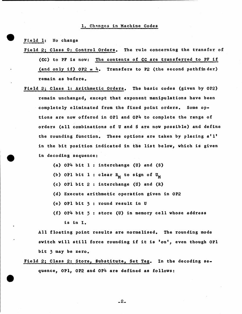
l. Ch~nges in Machine Codes
Field l: No change
Field 2; Class 0: Control Orders. The rule concerning the transfer of
(CC) to PF is now: The contents of ~C.are transferred to PF if
(and only if) OP2 ~ 4. Transfers to P2 (the second pathf~der)
remain as before.
Field 2; Class 1: Arithmetic Orders. The basic codes (given by OP2)
remain unchanged, except that exponent manipulations have been
completely eliminated from the fixed point orders. Some op
tions are now offered in OPl and OP4 to complete the range of
orders (all combinations of U and~ are now possible) and define
the rounding f~nction. These options are tak~n by placing a'l'
in the bit position indicated in tlie list below, which is given
in decoding sequence:
(a) oP4 bit 1: interchange (U) and (S)
(b) O~l bit 1 clear~ to sign of UM
(c) oPi bit 2 interchange (U) and (R)
(d) Execute arithmetic operation given in OP2
(e) OPl bit 3: round result in U
(£) OP4 bit 3: store (U) in memory cell whose address
is in 1.
All floating point results are normalised. The rounding mode
switch will still force rounding if it is 'on• J even though OPl
bit 3 may be zero.
Field 2; Class 2: Store, Substitute, Set Tag. In the decoding se
quence, OPl, OP2 and OP4 are defined as follows:
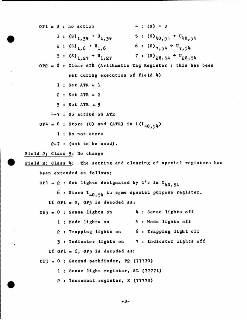
OPl • 0 . no action •
1 . (S)l,39 + Ul,39 •
2 : (S)l,6 + Ul,6
' : (S)l,27 + Ul,27
oPa. 6 .. Clear ATR. (Arith111etic •
set durii\g execution
i : Set ATR .. 1
2 Set AT& a a
3 Set ATR. '= 3
4•7: ~o Jctibrl on ATR
4 (S) + u
5 ( s) 40, 5 4 + u 40, 5 4
6 • <9>1,54 +,u1,54 •
7 • (S)28,54 + U28,54 •
Tag Register . this has . oi field 4)
OP4 • 0: Store (U) and (ATR) in L(I40 , 54)
1 Do not store
2•7 (not to be used).
Field 2; Class 3: No change
been
Field 2; Class 4: The setting and clearing of special registers has
been extended as follows:
OPl = 2: Set lights designated by l's in 140 , 54
6: Store 140 , 54 in some special purpose register.
If OPl = 2, OP3 is decoded as:
OP3 = 0: Sense lights on
1: Mode lights on
2 Trapping lights on
3: Indicator lights on
If OPl = 6, OP3 is decoded as:
4: Sense lights off
5 : Mode lights off
6: Trapping light off
7 Indicator lights off
OP3 = 0: Second pathfinder, P2 (77770)
1: Sense light register, SL (77771)
2: Increment register, X (77772)
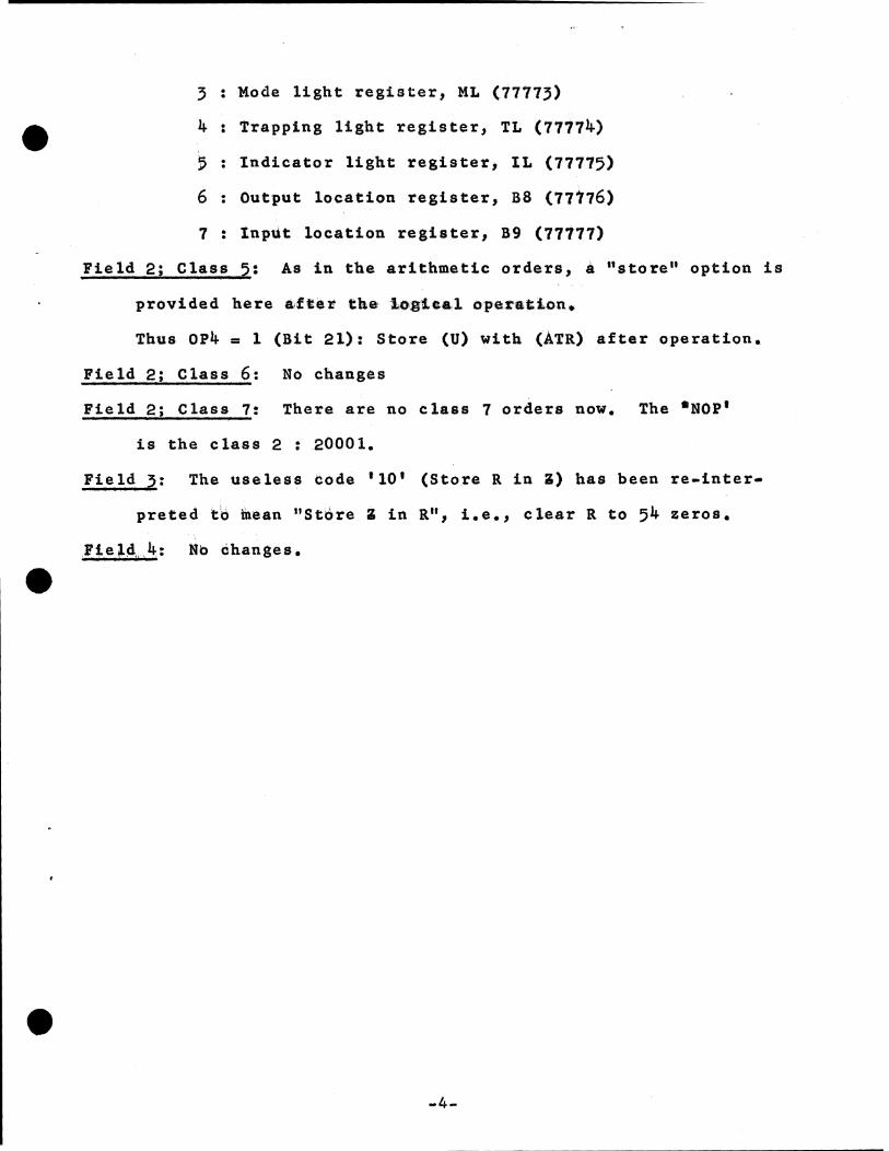
3: Mode light register, ML (77175)
4: Trapping light register, TL (77774)
5 : Indicator light register, IL (77775)
6: Output location register, B8 (77t76)
7: lnp~t location register, B9 (77777)
Field 2; Class 5: As in the arithmetic orders, a "store" option is
provided he1:e a,fCel' the i.oJJiea.l operation.,
Thus OP4 = l (Bit 21): Store (U) with (ATR) after operation.
Field 2; Class 6: No changes
Field 2; Class 7: There are no class 7 orders now. The •NOP'
is the class 2: 20001.
Field J: The useless code 1 10 1 (Store Rini) bas been re-inter
preted to fuean "Store 3 in R", i.e., clear R to 54 zeros.
F1el4.4: Nb dhanges.
-4-
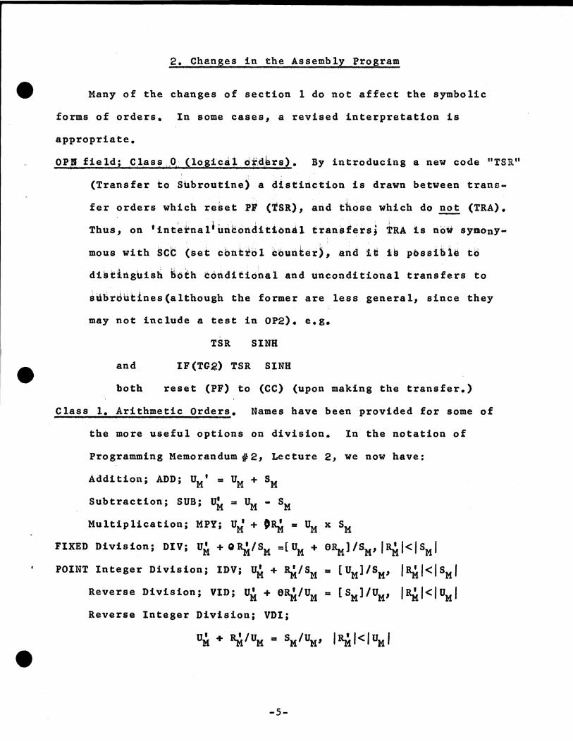
2. Changes in the Assembly Program
Many of the changes of section 1 do not affect the symbolic
forms of orders. In some cases, a revised interpretation is
appropriate.
OPH field; C.l.ass 011 (logica. l o~,d,brs). By introducing a new code "TSll"
(Transfer ~o Sbbro~tine) a distirtctioh is drawn between trans
fer orders which re~et PF {iSR), and those which do not (TRA).
Thus, on 'inte~nal*unbortdition~l transfersj TRA 1s now synony
mous With SCC (set cbntiol Cbunter), and itt ii p~ssibl~ to
di~~lrtgbis~ i6~h idrtditional and unconditional transfers to
subrJutines(altbough the former are less general, since they
may not include a test in OP2). e.g.
TSR SINH
and IF(TG2) TSR SINH
both reset (PF) to (CC) (upon making the transfer.)
Class 1. Arithmetic Orders. Names have been provided for some of
the more useful options on division. In the notation of
Programming Memorandum :fl, 2, Lecture 2, we now have:
Addition; ADD; uM• =UM+ SM
Subtraction; SUB; UM= UM• SM
Multiplication; MPY; U'+ M 01\i = UM x SM
FIXED Division; DIV; u• M + Q ~ISM =[ UM + e~J/sM, 18Ml<lsMI
POINT Integer Division; IDV; u• + 1).i/S M M = [ UM] /SM' I l\i I< I SM I Reverse Division; VID; UM + 61\i/UM = [ SM] /UM, l~l<IUMf
Reverse Integer Division; VDI;
-5-
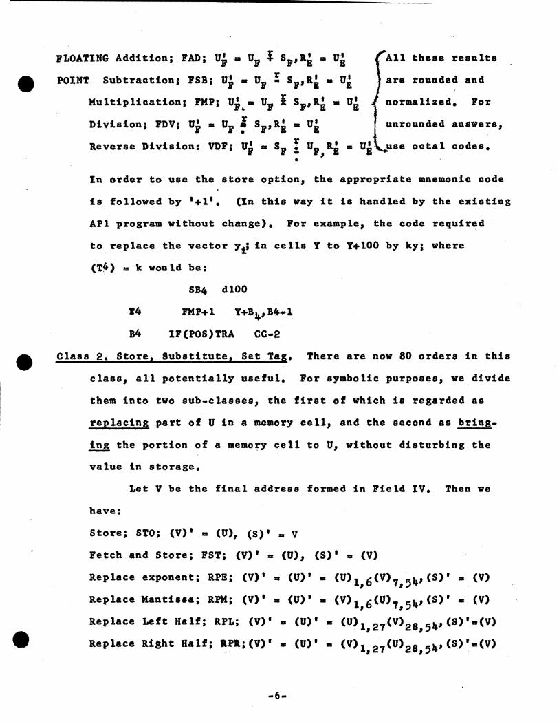
JLOATING Addition;. FAD; Uj. • u1 i s1 ,R1 • Ug
POINT subtraction; rsB; UP• u1 !: s1,a1 • u~ Multiplication; PMP; u;.,• u, i s1 ,ll~ • u8
i t 1' t I Divis on; FDV; u1 • u1 ! s1,a1 • u1
All these re~ulta
are rounded and
normalized. For
unrounded answers,
Reverse Division: VDF; u; • s1 I u,,Ri • u1- use octal codes • •
In order to use the store option, the appropriate mnemonic code
is followed by •+1•. (ln this way it ia handled by the existing
APl program without change)., For example, the code required
to replace the vector Ye in cells Y to Y+lOO by ky; where
(T4) = k would be:
SB4 dlOO
r4 FMP+ 1 Y+B 4, B/f.1:
B4 lF(POS)TllA cc-2
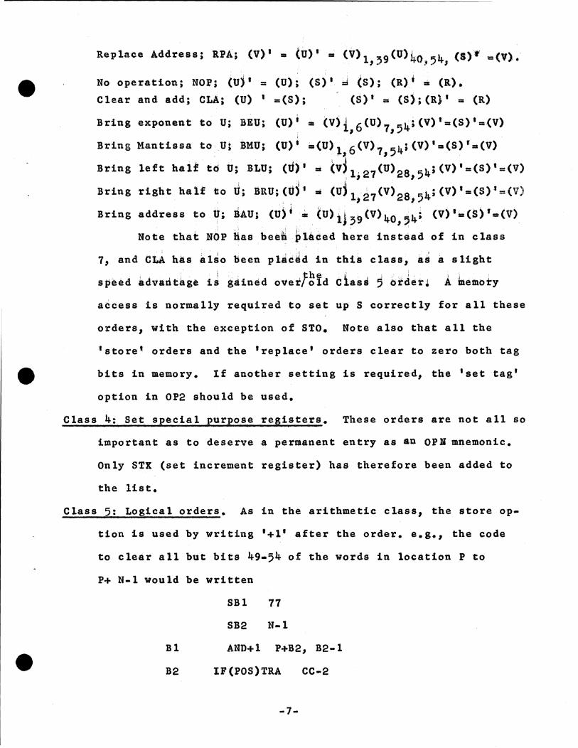
Class 2. Store, lubstitute1 Set Tag. There are now 80 orders in this
class, all potentially useful. For symbolic purposes, we divide
them into two sub-classes, the first of which is regarded as
replacing part of U in a memory cell, and the second as bring
.!!J. the portion of a memory cell to u, without disturbing the
value in storage.
Let V be the final address formed in Field IV. Then we
have:
Store; STO; (V)' • (U), (S)' • V
Fetch and Store; FST; (V) 1 • (U), (S) 1 • (V)
Replace exponent; RPE; (V)' • (U)' • (U)1,6(V)7,54,(S)' • (V)
Replace Mantissa; RPM; (V)' • (U)' • (V>1,6CU)7,54,CS)' • (V)
Replace Left Half; llPL; (v)• • (U)' • (U) 1, 27 (v) 28, 54,cs)'•(V)
Replace Ri8ht Half; &n;(V)' • (U)' • (V) 1, 27 (l1)2 a,,4' (S)'a(V)
-6-
Replace Address; RPA; (V)' • (U)' • (V) 1139(U)40., 54, (&ff =(V).
No operation; NOP; (U) 1 = (U) ~ (S) 1 mi (S); (R) ~ • (R) • Clear and add; CLA; (U) 1 • (S); . (S) 1 • ($); (R)' = (R)
Bring exponent to U; BEU; (U)i • (Vjt16 (u) 715~~(V)'=(S) 1 =(V) i
Bring Mantissa to U; ~MU; (U)' •(1J);t, 6 (v) 7154;(V)'•(S) 1•(V)
Bring left half tQ b; BLU; (U)' • cv~ 1, 27 (u) 28, 54;(V)'=(S)'=(V)
Bring right half tto U; ~RU;(uS• .. (tJjl;27(V)28,5lt_;(V)'•(S)'=(V)
Bring address to.U; BAU; cui~ •.(U)iJ,~(v) 40 ,1,) (V)'•(S) 1•CV) ' . : ' , I ,
Note that NOP lias beeh ~l!ded here instead of in class
11 and tLA has a1so been ptjcdd tn tht~ c1ass, •• a slight
speed adv~nt~g• 1J 8Jined overfg!d class, btJ$r, A bemoty
a~cess is normally required to set up S correctly for all these
orders, with the exception of STO. Note also that all the
'store• orders and the •replace• orders clear to zero both tag
bits in memory. tf another setting is required, the •set tag•
option in OP2 should be used.
Class 4: Set special purpose registers. These orders are not all so
important as to deserve a permanent entry as au OPB mnemonic.
Only STX (set increment register) has therefore been added to
the list.
Class 5: Logical orders. As in the arithmetic class, the store op
tion is used by writing '+1' after the order. e.g., the code
to clear all but bits 49-54 of the words in location P to
P+ N-1 would be written
SBl 77
SB2 N-1
Bl AND+l P+B2 1 B2-1
B2 IF(POS)TRA cc-2
-7-
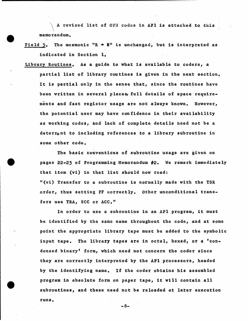
\ A revised list of Ol?N codes in A.Pl is attached to this· \ ~
memorandum.
Field,:. The mnemonic 11R + 1 11 is unchanged, but ls interpreted as
indicated in Section t. Library Routines. As a guide to what is available to coders, a
partial list of libtary routines is given in the next section.
It is partial only in the sense that, since the routines have
been written in se"7eral places, full details of space require
ments and fast -register usage are not always knbwn. However,
the potential user may have confidedce in their availability
as working ~odes, •nd lack of complete details heed not be a
deterrent to includirtg references to a library slibroutine in
some other code.
The basic coiventiona ol subroutine usage are kiven on
p~ses 22-2, of Programmi~g Memorandum 12. We re-ark immediately
that item (vi) in that list should now read:
"(vi) Transfer to a subroutine is normally made with the TSR
order, thus setting PF correctly. Other unconditional trans-
fers use TRA, sec or ACC."
In order to use a subroutine in an APl program, it must
be identified by the same name throughout the code, and at some
point the appropriate library tape must be added to the symbolic
input tape. The library tapes are in octal, hexad, or a 'con
densed binary• form, which need not concern the coder since
they are correctly interpreted by the APl processors, headed
by the identifying name. If the ·coder obtains his assembled
program in absolute form on paper tape, it will contain all
subroutines, and th•se rieed not be reloaded at later execution
runs. -8-
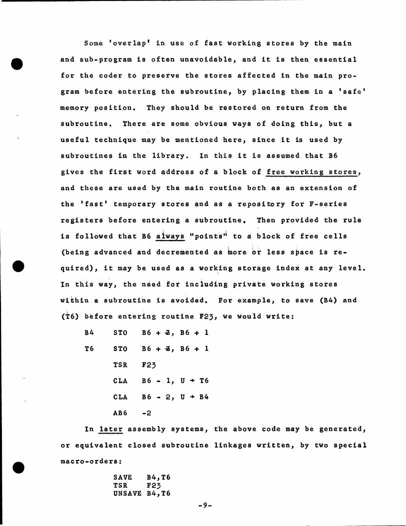
Some 'overlap• in use of fa~t working stores by the main
and sub-program is often una~oida~le, and it is then essential
for the coder t6 prese~ve the $tores atfected in the main pro-
gram before entering the subroutine, by placing them in a 'safe'
memory position~ They should be restored on return from the
subroutine. There ate some obvious ways of doing this, but a
useful technique may be mentioned here, since it is used by
subroutines in the library. In this it is assumed that B6
gives the first word address of~ block of free working stores,
and these are used by the main routine both as an extension of
the 'fast' temporary stores and as a repository for F-series
registers before entering a subroutine. Then provided the rule
is followed that B6 a1ways "points•• to • block of free cells
(being advanced and decremented as bore bt less space 1$ re
quired), it may ~e use~&$ a wotkirig storage inde~ at any level. l
In this ia~, the nj~d tot inciuding priv~t~ ~orking stores
within a subroutihe is avoided. For example, to save (B4) and
d:6) before entering routine F23, we would write:
B4 STO B6 + -a, B6 + 1
T6 STO B6 + ..;, B6 + 1
TSR F23
CLA B6 • 1, u + T6
CLA B6 - 2, u + B4
AB6 -2
In later assembly systems, the above code may be generated,
or equivalent closed subroutine linkages written, by two special
macro-orders:
SAVE B4,T6 TSR F23 UNSAVE B4,T6
-9-
le
and in planning complex systems of routines, it is convenient
to employ an abbreviation such as this until final details of
subroutine usage have been worked out.
It should be noticed that some of the data input routines
will use 86 as an indication of where to put the numbers being
read in; they will advance (B6) by an amount corresponding to
the number of stores used, and it is therefore important for
the coder to insure that (B6) is reduced to its initial value
if a data input routine of this type is used within another sub
routine. The alternative procedure, of al~ays retaining ehough
storage spabe for initial and intermediate data within a pro•
gram, may still be used.
Provision is made for handling arrays of one or two dimen•
sions "semi-automatically" by means of the type 1 codewords of
Programming Memorandum 11. This leads to greater uniformity,
shorter calling sequences, and little appreciable loss of time
or space compared with conventional methods. For these reasons,
only the "short forms" of subroutines are given in the following
list. (The routines are also available with conventional calling
sequences.) To summarize the codewords in their present form,
it is assumed that each refers to a block of stores of length
L, which may contain numbers of one sort or another, or more
codewords. In the latter case, the IA (indirect address) bit
is turned.!!.!!. in the codeword. If the consecutive stores contain
elements a 1,a2 , ••• at, then the codeword A contains a Bl-modifi·
cation bit, and has in its address part the location preceding
the store containing a 1• Hence, it is always the case that to
obtain a 1 , it is sufficient to write the code:
SBl i CLA *A. -10-
Similarly, for matrices, to obtain the element ai'j' it is
sufficient to write:
SBl 1 SB2 j CLA *A.
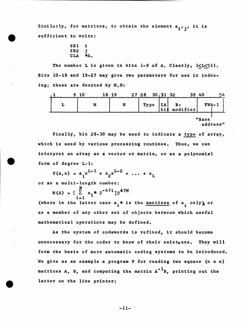
The number Lis given in bits 1-9 of A. Clearly, l<L~511.
Bits 10-18 and 19-27 may give two parameters for use in index-
ing; these are denoted by M,N:
9 10 18 19
L I N
"Base address"
Finally, .l>it 28-30 may be used to indicate a type of array,
which is used by various processing routines. Thus, we can
interpret an a~ray as i vector or matrix, or as a polynomial
form of degree L-1:
L-1 P(A,x) = a 1x
or as a multi-length number: N
M(A) = [ L. a * 2-47iJ247M i=l i
(where in the latter case a 1 • is the mantissa of a 1 only~ or
as a member of any other set of objects between which useful
mathematical operations may be defined.
As the system of codewords is refined, it should become
unnecessary for the coder to know of their existence. They will
form the basis of more automatic coding systems to be introduced.
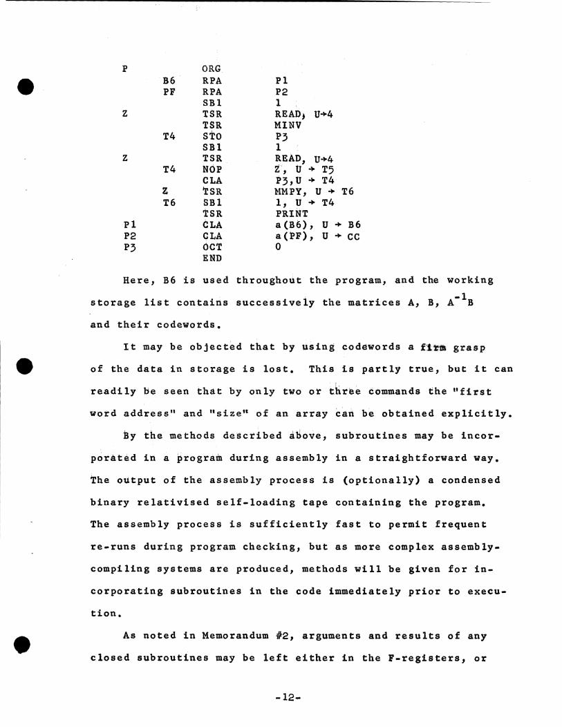
We give as an example a program P for reading two square (n x n)
-1 matrices A, B, and computing the matrix A B, printing out the
latter on the line printer:
-11-
•
p ORG B6 RPA Pl PF RPA P2
SBl 1 z TSR RE ADJ U+4
TSR Ml NV T4 STO P3
SBl 1 z TSR READ, U+4
T4 NOP z, U + T5 CLA P3,U + T4
z TSR MMPY, u + T6 T6 SBl 1, U + T4
'l:SR PRINT Pl CLA a(B6), u + B6 P2 CLA a(l>F), u + cc P3 OC'r 0
END
Here, B6 is used throughout the program, and the working
storage list contains successively the matrices A, B, A- 1B
and their codewords.
It may be objected that by using codewords a U.fll grasp
of the data in storage is lost. This is partly true, but it can
readily be seen that by only two or three commands the ttfirst
word address" and "size" of an array can be obtained explicitly.
by the methods deSctibed itiove, subroutines may be incor-
porated in a program during assembly in a straightforward way.
the output of the assembly process is (optionally) a condensed
binary relativised self-loading tape containing the program.
The assembly process is sufficiently fast to permit frequent
re-runs during program checking, but as more complex assembly-
compiling systems are produced, methods will be given for in-
corporating subroutines in the code immediately prior to execu-
tion.
As noted in Memorandum #2, arguments and results of any
closed subroutines may be left either in the F-registers, or
-12-
the PF-list (i.e., the conventional calling sequences following
the transfer order), or anywhere else addressed by one of these
registers. We shall describe the subroutine using standard
abbreviations for F-registers, and the notation PO,Pl, ••• ,Pk
for members of the PF-list. Then let the notation:
(1)
denote the subrobtine N withs output values and t input values,
where the Y's and x•s are generally chosen from the set of F-
register names or the Pi's• Thus:
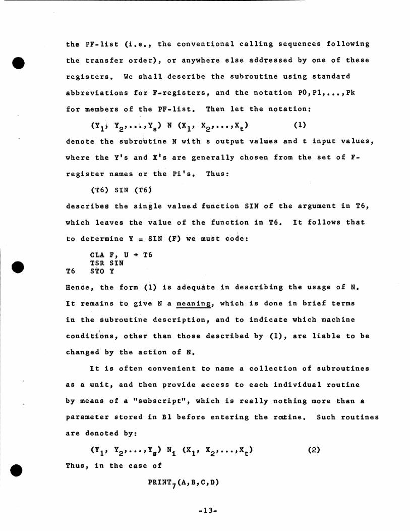
(T6) SIN (T6)
describ$8 the sinile value4 function SIN of the argument in T6,
which leaves the value of the function in T6. It follows that
to determine Y = SIN (F) we must code:
CLA F, U + T6 TSR SIN
T6 STOY
Hence, the form (1) is adequ~te in describing the usage of N.
It remains to give Na meaning, which is done in brief terms
in the subroutine description, and to indicate which machine
conditibns, other than those described by (1), are liable to be
changed by the action of N.
It is often convenient to name a collection of subroutines
as a unit, and then provide access to each individual routine
by means of a 0 subscript", which is really nothing more than a
parameter stored in Bl before entering the raJ:ine. Such routines
are denoted by:
(Yl, Y2, ••• ,Y.) Ni (Xl, x2, ••• ,xt)
Thus, in the case of
PRINT7(A,B,C,D)
-13-
(2)
• the calling sequence would be:
SBl TSR ... .. .. .a
7 PRINT A B c D
ln the choice of N, we have tried to select the ueual names
for elementary functions. (These are mostly evaluated by means
of ecouo•l••• pol,..oaiaala 4ertve4 a& th• lxplorattoa aa4 Pro•
cluctioa l.eaearch Df.vtalon of the Shell Developaeat Coapany.)
Often, routines which effect the same transformation by different
methods will have the same name. There seems to be no dis•
advantage in this as long as subroutine tapes are selected by
hand, and it does have the advantage of keeping the set of
different names to minimum.size. Some subroutines, e.g. SlH
and cos, are grouped together for obvious reasons, and appear
on the same physical tape.
Bot all possible functions have been placed in the library
list, and many others are available. Some notes on these, and
on the array routines which do not use codewords, may be seen -at the Computer Project. However, it is often advantageous for
the coder to write his own supplementary routines as they are
required, in order to minimise overlapping in the use of fast
stores.
·14-
•
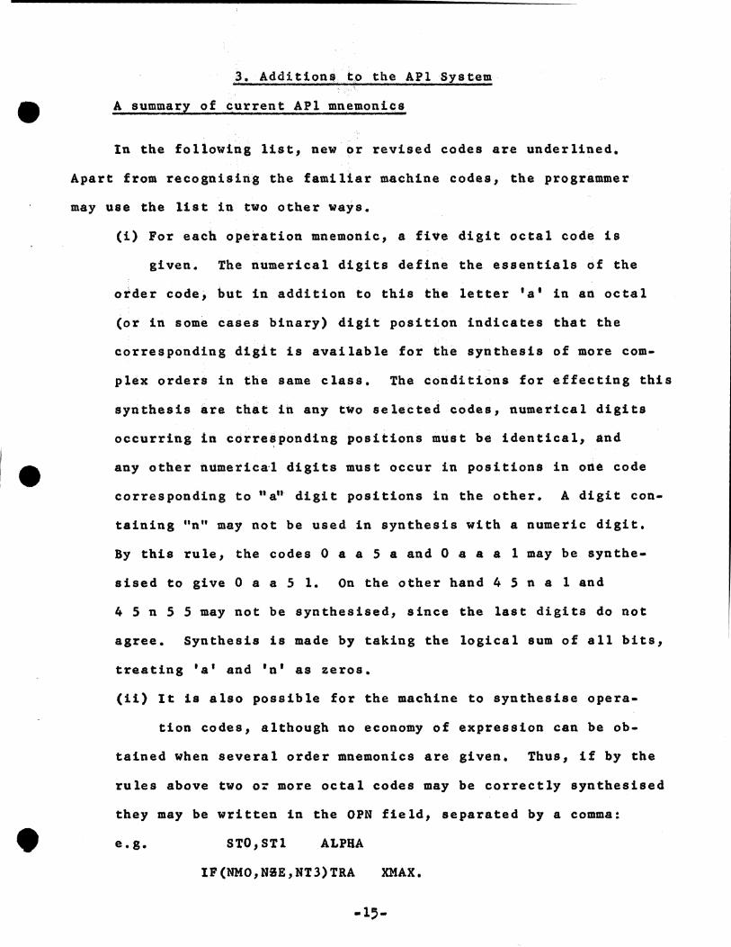
3. Additions to the APl System
A summary of current APl mnemonics
In the following list, new or revised codes are underlined.
Apart from recognising the familiar machine codes, the programmer
may use the list in two other ways.
(i) For each operation mnemonic, a five digit octal code is
given. The numerical digits define the essentials of the
order code, but in addition to this the letter •a• in an octal
(or in some cases binary) digit position indicates that the
corresponding digit is available for the synthesis of more com
plex orders in the same class. The conditions for effecting this
synthesis are that in any two selected codes, numerical digits
occurring in corresponding positions must be identical, and
any other numerical digits must occur in positions in one code
corresponding to"~' digit positions in the other. A digit con
taining "n" may not be used in synthesis with a numeric digit.
By this rule, the codes O a a 5 a and O a a a 1 may be synthe
sised to give O a a 5 1. On the other hand 4 5 n a 1 and
4 Sn S 5 may not be synthesised, since the last digits do not
agree. Synthesis is made by taking the logical sum of all bits,
treating 'a' and 'n' as zeros.
(ii) It is also possible for the machine to synthesise opera-
tion codes, although no economy of expression can be ob
tained when several order mnemonics are given. Thus, if by the
rules above two o~ more octal codes may be correctly synthesised
they may be written in the OPN field, separated by a comma:
e.g. STO,STl ALPHA
IF(NMO,N~E,NT3)TRA XMAX.
-15-
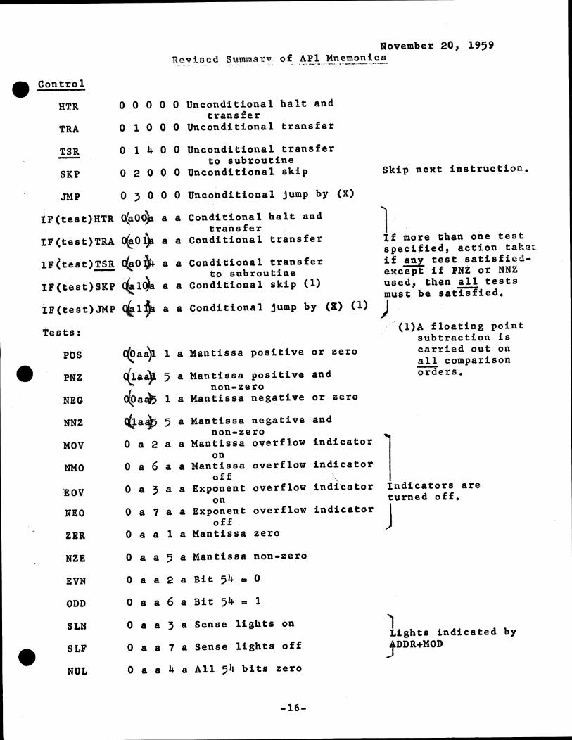
November 20, 1959 Revised Summa~v of APl Mnemonics
_,.,, <o'' ~ " , :-,•'•• > ~· L .. ,,··-·"!'f••n·-·' .. ,.,_.; .... -,.,... ... -
Control
HTR O O O O O Unconditional halt and transfer
TRA O l O O O Unconditional transfer
TSR -SKP
O l 4 0 0 Unconditional transfer to subroutine
0 2 0 0 0 Unconditional skip
JMP O 3 0 0 0 Unconditional jump by (X)
IP(test)BTR t(ao~ a a Conditional halt and transfer
IF(test)TRA ~ol)i a a Conditionai transfer
lF(test)!!! <l'e,oj.. a a Conqitional transfer 1;o subroutine
IF(test)SKP ~1{11 a a Conditional skip (1)
tF(test)JMP ~1~ a a Conditional jump by (K) (1)
Tests:
POS
PNZ
NEG
NNZ
MOV
NMO
'EOV
NEO
ZER
c(t>aa)l
~·a) tl{>a«IJ <4a15
la Mantissa positive or zero
5 a Mantissa positive and non-zero
la Mantissa negative or zero
5 a Mantissa negative and non-zero
O a 2 a a Mantissa overflow indicator on
O a 6 a a Mantissa overflow indicator off '· O a 3 a a Exponent overflow indic:ator on
O a 7 a a Exponent overflow indicator off
O a a 1 a Mantissa zero
NZE O a a 5 a Mantissa non-zero
EVN O a a 2 a Bit 54 • 0
ODD O a a 6 a Bit 54 = 1
SLN
SLF
O a a 3 a Sense lights on
O a a 7 a Sense lights off
NUL O a a 4 a All 54 bits zero
-16-
Skip next instruction.
lf. . . ' 1 •ore tihan one test specified, action takeL il any test satisfiedexcept if PNZ or NNZ used, th-n all tests must be satisfied.
J , ~(l)A floating point
subtraction is carried out on all comparison orci'ers.
l Indicators are turned off.
J
I Lights indicated by
jDDR+MOD
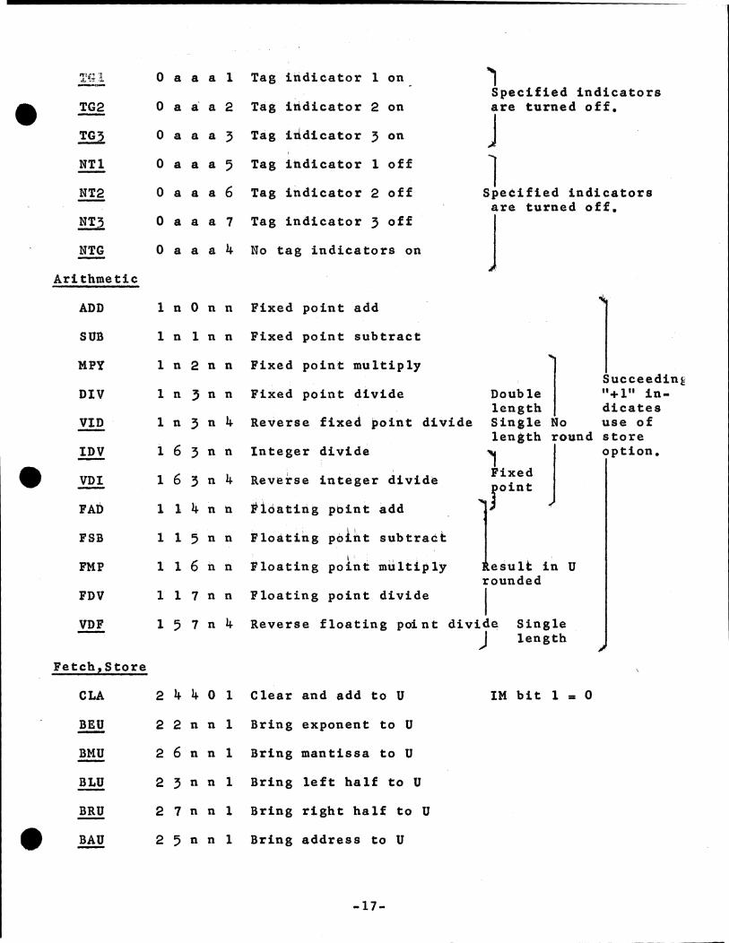
TG2 -TG3
NTl
NT2 -!ll NTG
Arithmetic
O a a a 1 Tag indicator 1 on
O a~ a 2 tag irtdicator 2 on
O a a a 3 Tag indicator 3 on
O a a a 5 Tag indicator 1 off
O a a a 6 Tag indicator 2 off
O a a a 7 Tag indicator 3 off
O a a a 4 No tag indicators on
ADD 1 n On n Fixed point add
SUB l n 1 n n Fixed point subtract
MPY
DIV
VID -IDV
VDI
FAD
FSB
FMP
FDV
l n 2 n n
1 n 3 n n
1 n 3 n 4
l 6 3 n n
1 6 3 n 4
1 l 4 n n
1 1 5 n n
1 1 6 n n
1 1 7 n n
Fixed point multiply
Fixed point divide
Reverse fixed point divide
Integer divide
Reverse integer divide
Fioatirig pbint add
floating poiht subtract I,
Floating point multiply
Floating point divide
' Specified indicators are turned off.
j l Specified indicators are turned off.
j
~:::!: l Single No
i::::h Jround
joint .
lsult in U rounded
I
Succeeding "+1" indicates use of store option.
VDF 1 5 1 n 4 Reverse floating point divide )
Single length
Fetch,Store
CLA 2 4 4 0 1 Clear and add to U IM bit 1 = 0
BEU 2 2 n n 1 Bring exponent to U
BMU 2 6 n n 1 Bring mantissa to U
!.hl! 2 3 n n l Bring left half to U
BRU 2 7 n n 1 Bring right half to U
BAU 2 5 n n 1 Bring address to U
-17-
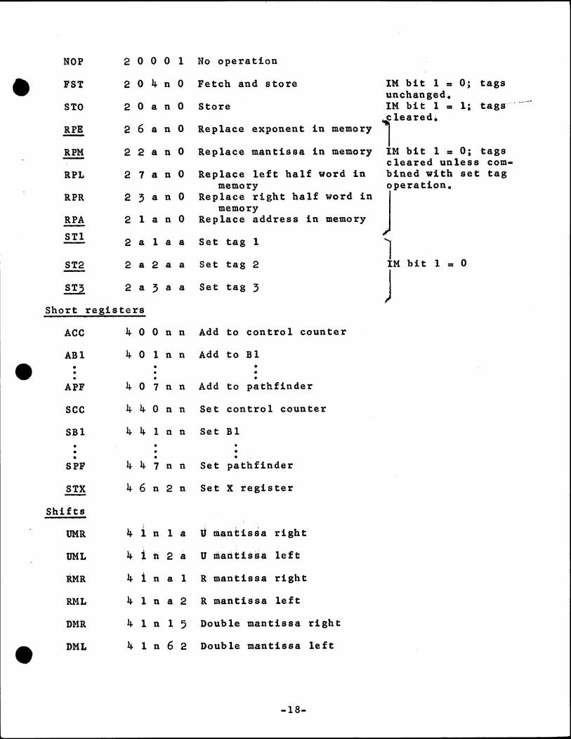
NOP 2 0 0 0 1 No operation
FST 2 0 4 n 0 retch and store IM bit 1 = O; tags unchanged.
STO 2 0 a n 0 Store tM bit 1 111 1; tags· . --··-
RFI 2 6 a n 0 - Replace exponent in memory ilearedi
RPM 2 2 a n O Replace mantissa in memory IM bit 1 = O; tags - cleared unless com-RPL 2 7 a n 0 Replace left half word in bined with set ta~
memory J~eration. RPR 2 3 a n 0 Replace right half word in
memory RPA 2 1 a n 0 Replace address in memory -STl 2 a 1 a a Set tag 1 l ST2 2 a 2 a a Set tag 2 tM bit 1 = 0 -
J ST3 2 a 3 a a Set tag 3
Short re;ister_s
ACC 4 0 0 n n Add to control counter
ABl 4 0 1 n n Add to Bl • • • • . • • • •
APF 4 0 1 n n Add to pathfinder
sec 4 4 0 n n Set control counter
SBl 4 4 1 n n Set Bl • • • • • • • • • .
SPF 4 4 1 n n Set pathfinder
!!! 4 6 n 2 n Set X tegister
Shifts
4 ; v ,· i
UMR 1 i1. 1 a mantissa right
UML 4 i tl 2 a u tiiaritissa left
DIR 4 i n a 1 R mantissa right
RML 4 1 n a 2 R mantissa left
DMR 4 1 n l 5 Double mantissa right
• DML 4 l n 6 2 Double mantissa left
-18-
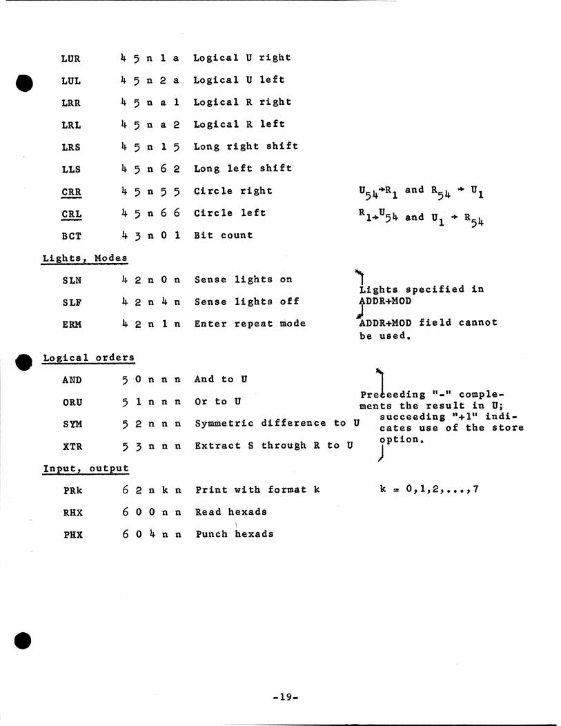
LUR 4 5 n 1 a Logical U right
LUL 4 5 n 2 a Logical U left
LRR 4 5 n a 1 Logical R right
LRL 4 5 n a 2 Logical R left
LRS 4 5 n 1 5 Long right shift
LLS 4 5 n 6 2 Long left shift
CRR
CRL -4 5 n 5 5 Circle right
4 5 n 6 6 Circle left
BCT 4 3 n O 1 Bit count
Lights, Modes
SLN 4 2 n On Sense lights on
SLF 4 2 n 4 n Sense lights off
ERM 4 2 n 1 n Enter repeat mode
Logical orders
AND 5 0 n n n And to U
ORU 5 1 n n n Or to U
u54+a1 and a54 + u1
Rl+U54 and u1 + a54
~ Lights specified in
JDDR.+MOD
ADDR+MOD field cannot be used.
SYM 5 2 n n n
Pr)eeding "-" colllplements the result in U;
succeeding 0 +111 indicates use of the store Symmetric difference to U option.
) XTR 5 3 n n n Extracts through R to U
Input, output
PRk 6 2 n kn Print with format k k = 0,1,2, ••• ,7
RHX 6 0 0 n n Read hexads
PHX 6 0 4 n n Punch hexads
-19-
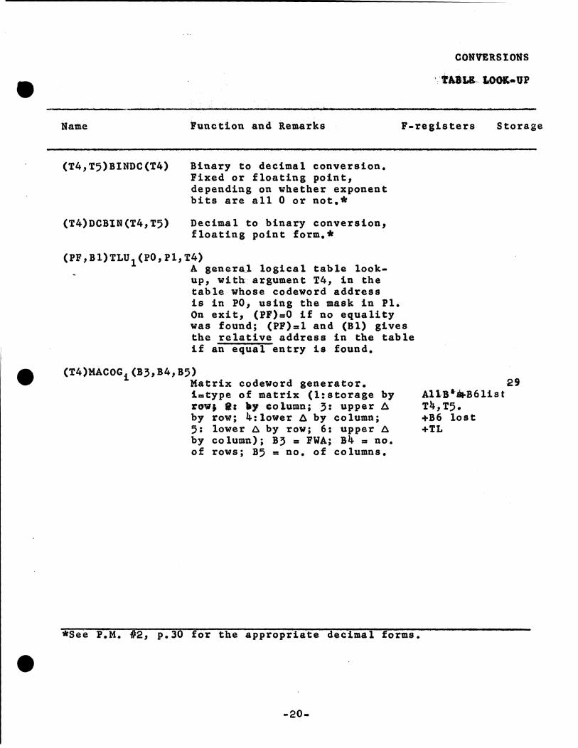
CONVERSIONS
Name Function and Remarks F-registers Storage
(T4,T5)BINDC(T4)
(T4)DCBlN(?4.,T5)
Binary to decimal conversion. Fixed or floating point, depending on whether exponent bits are all O or not.*
Decimal to binary conversion, floating point form.*
(PF,Bl)TLU (PO.,Pl.,T4) 1 A genera,l logical table look-
. up., with argument T4, in the table whose codeword address is in PO, using the mask in Pl. On exit, (PF)=O if no equality was found; (PF)•l and (Bl) gives the relative address in the table if an equal entry is found.
(T4)MACOGi(B3,B4,B5) Matrix codeword generator. i=type of matrix (l:storage by roWJ I: lly eolumn; 3: upper A by row; 4:lower A by column; 5: lower A by row; 6: upper A by column); B3 = FWA; B4 = no. of rows; B5 = no. of columns.
*See P.M. 12, p.30 for the appropriate decimal forms.
-20-
29 AllB•8f.B6list T4,T5. +B6 lost +TL
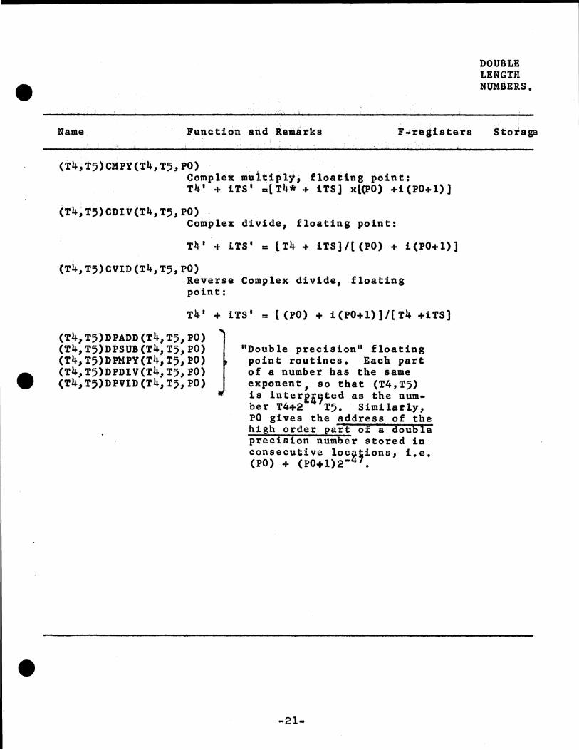
Name Function and lemirks ,.registers
(T4,T5)CMPY(t4,T5,PO) · .·. . .. Complex multiply, floating point: T4' + iTS 1 m[T4• + iTS] x((PO) +i(PO+l)]
(T4;t;)CDIV(T41 T5,PO) Complex divide, floating point:
T4' + iTS' = [T4 + iTS]/[(PO) + i(PO+l))
(T41 T5)CVID(T41 T5 1 PO) Reverse Complex divide, floating point:
T4 1 + iTS 1 =((PO)+ i(PO+l)]/{T4 +iTS)
(T41 T5)DPADD(T41 T5 1 PO) (T4,T5)DPSUB(T41 T5,PO) (T41 T5)DPMPY(T41 T5,PO) (T4,T5)DPD1V(T41 T5 1 PO) (T41 T5)DPV1D(T4,T5 1 PO)
"Double precision" floating point routines. Each part of a number has the same exponent, so that (T4,T5) is intere,,ted as the number T4+2 T5. Similarly, PO gives the address of the high orde,r part of a double precision number stored in· consecutive locfiions, i.e. (PO)+ (PO+l)2• •
-21-
DOUBLE LENGTH NUMBERS.
Stotage
l:. i...w .. J.:..,,...,. ·•'•"'- ~ FUNCTIONS
e .•. - .. _ .... _,_ ···-··~·~·····~·· ........ .,.~ """ .. """"'""....._
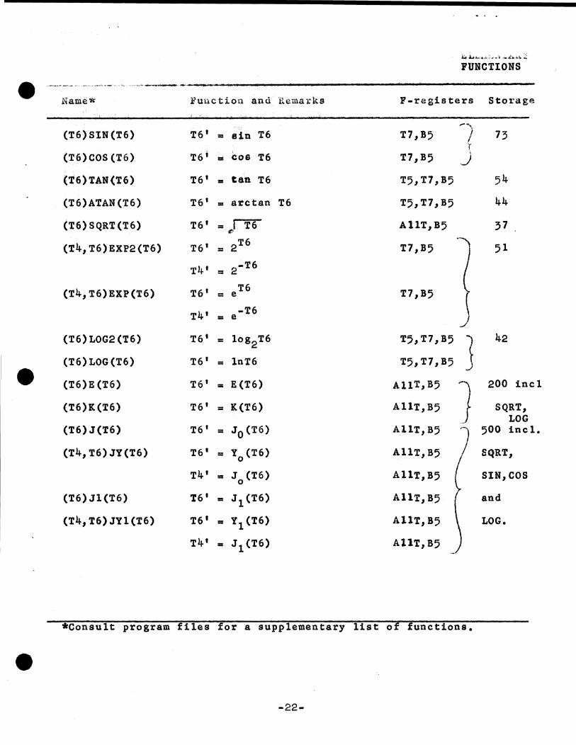
Name* Function and Remarks P'-registers Storage
(T6)SlN(T6) T6' = sin T6 T7,B5 ,-)
73 r
(T6)COS (T6) T6' • cos T6 T7,B5 J (T6)TAN(T6) T6' • tan T6 T5,T7,B5 54
(T6)ATAN(T6) T6 1 = arctan T6 T5,T7,B5 44
(T6) SQRT (T6) T6' = IT6 A11T,B5 37 . ',ti-
(T41 T6)EXP2(T6) T6' = 2T6 T7 1 B5 51
T4' = 2-T6
(T41 T6)EXP(T6) T6 1 = e T6 T7,B5
T4' • e -T6
(T6) LOG2 (T6) T6 1 = log2T6 T5,T7,B5 j 42
(T6)LOG(T6) T6 1 = lnT6 T5,T7,B5
(T6)E(T6) T6 1 = E (T6) Al1T,B5 ] 200 incl
(T6)K(T6) T6' = K(T6) AllT,B5 SQRT, LOG
(T6) J(T6) T6' = J 0 (T6) A11T,B5 l 500 incl.
(T41 T6)JY(T6) T6 1 = Y0 (T6) AllT1 B5 SQRT,
T4' = J 0 (T6) AllT, B5 SIN,COS
(T6)Jl(T6) '?6. = J 1(T6) A11T,B5 and
(T4,T6)JYl(T6) T6 1 • Y1(t6) AllT,B5 LOG.
T4' • J 1(T6) A11T,B5
*Consult program files for a supplementary list of functions.
-22-
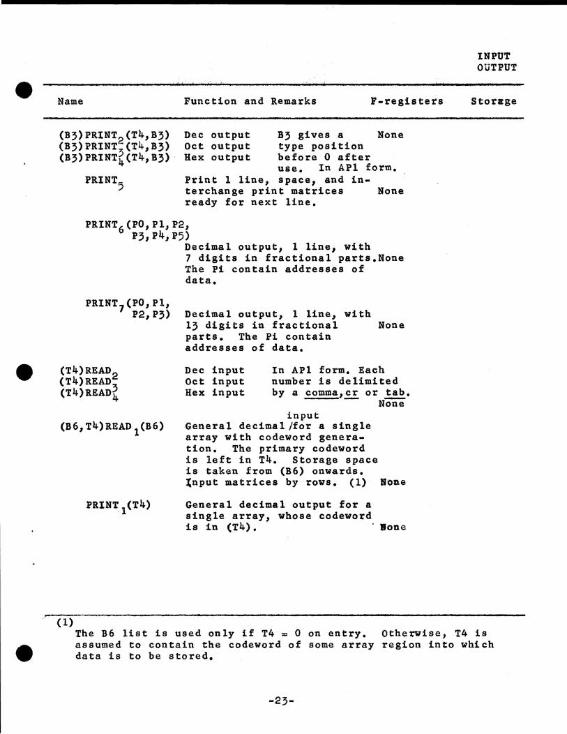
Name Function and Remarks F-registers
(B3)PRINT2 (T4,B3) Dec output (B3)PRINT;,(T41 B3) Oct output (B3)PRINT,(T41 B3) · Hex output
B3 gives a None type position before O after use. In APl form.
PRINT5 Print l line, space, and interchange print matrices ready for next line.
None
PR.INT6 (PO, Pl., P21
P3 1 P4, P5)
PRINT7 (PO, Pl, P21 P3)
(T4)READ2 (T4)READ:5 (T4)B.EAD4
(B61 T4)READ l (B6)
PRINT1 (T4)
(1)
Decimal output., 1 line, with 7 digits in fractional parts.None The Pi contain addresses of data.
Decimal output, 1 line, with 13 digits in fractional None parts. The Pi contain addresses of data.
Dec input Oct input Hex input
In APl form. Each number is delimited by a comma,cr or tab.
- None input
General decimal/for a single array with codeword generation. The primary codeword is left in T4. Storage space is taken from (B6) onwards. tnput matrices by rows. (1) · llene
General decimal output for a single array, whose codeword is in (T4). · lone
INPUT OUTPUT
Storage
The B6 list is used only if T4 = 0 on entry. OtheTWise, T4 is assumed to contain the codeword of some array region into which data is to be stored.
-23-
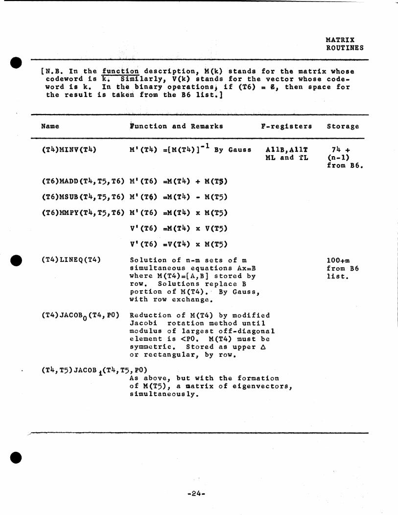
MATRIX ROUTINES
[N.B. In the function description, ~(k) stands for the matrix whose codeword is k. Similarly, V(k) stands for the vector whose codeword is k. In ~h~ binary operations) if (T6) = 8 1 then space for the result is taken from the B6 list.]
Name
(T4}MINV (T4)
(T6)MADD(T4,T51 T6)
(T6)MSUB(T41 T5 1 T6)
(T6)MMPY(T4,T5,T6)
(T4)LINEQ(T4)
(T4)JACOB0 (T4,PO)
!unction and Remarks F-registers
M'(T4) =[M(T4)}-l By Gauss AllB,Allt ML and ·.rL
M 1 (T6) =M(T4) + M(T~)
M' (T~) =M(T4) • M(T5)
Mt (T6) =M(T4) x M(T5)
V' (T6) =M(T4) x V(T5)
V'(T6) =V(T4) x M(T5)
Solution of n-m sets of m simultaneous equations Ax=B where M(T4)=[A,B] stored by row. Solutions replace B portion of M(T4). · By Gauss, with row exchange.
Reduction of M(T4) by modified Jacobi rotation method until modulus of largest off-diagonal element is <PO. M(T4) must be symmetric. Stored as upper A or rectangular, by row.
(T4 1 T5)JACOBi(T41 T5,PO) As above, but with the formation of M(T5), a matrix of eigenvectors, simultaneously.
-24-
Storage
74 + (n-1) from B6.
lOO+m from B6 list.
•
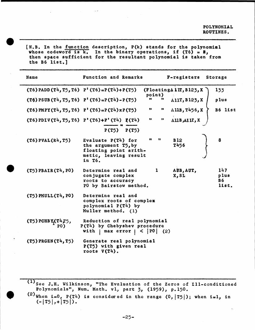
POLYNOMIAL llOUTlNES.
[N.B. In the function description, P(k) stands for the polynomial whose codeword is k. In the binary operations, if (T6) = 11 then space sufficient for the resultant polynomial is taken from the B6 list.]
Name
(T6)PADD(T41 T5,T6)
(T0)PSUB(T41 T5,T6)
(T6)PMPY(T4,T5 1 T6)
(T6)PDIV(T4,T51 T6)
(T6)PVAL(R4,T5)
(T5) PBAIR(T4, PO)
(T5) PMULL(T4, PO)
(T5) PCBB\(T4,r5, PO)
(T5)PRGEN(T41 T5)
Function and &emarks F-registers Storage
P1 (T6)=P(T4)+P(T5) (Ploating4.11T, Bl23,X point)
P1 (T6)=P(T4)-P(T5)
P'(T6)=P(T4)xP(T5)
P'(T6)+P'(T4) '(T4) ·-P(T5) P(T5)
Evaluate P(T4) for the argument T5 1 by floating point arithmetic, leaving result in '?6.
.. It
H
..
Determine real and 1 conjugate complex roots to accuracy PO by Bairstow method,
Determine real and complex roots of complea polynomial P(T4) by Muller method, (1)
n
..
..
ti
Reduction of real polynomial P(T4) by Chebyshev procedure with f max error I < IPOf (2)
Generate real polynomial P(T5) with given real roots V(T4).
\
AllT, 8123, X
All!, T456, X
AUB,AJU,X
Bl2 T456
AIJB,AUT, X1 SL
...,,
J
133
plus
B6 list
8
147 plus B6 list,
(l)See J.H. Wilkinson, "The Evaluation of the Zeros of Ill-conditioned folynomials", Num. Math. vl, part 3, (1959), p.150 •
<2 >when i=O, P(T4) is consid~ed in the range (O, IT5j); when ial, in <- I T5 I , + I T5 I ) ,
-25-
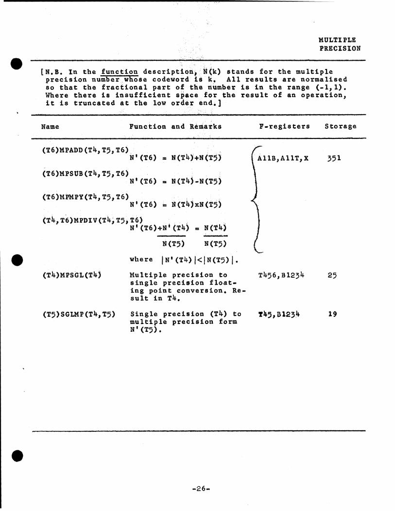
MULTIPLE PRECISION
[N.B. In the function description~ N(k) stands for the multiple precision number.whose codeword is k. All results are normalised so that the fractional part of the number is in the range (-1,l). Where there is insufficient space for the result of an operation, it is truncated at the low order end.]
Name Function and Remarks F-registers Storage
(T6)MPADD(T41 T5,T6) N'(T6) = N(T4)+N(T5) 351 AllB,AllT1 X
(T6)MPSUB(T41 T5 1 T6) N•(T6) = N(T4)-N(T5)
(T6)MPMPY(T4,T5,T6) N1 (T6) = N(T4)xN(T5)
(T41 T6)MPDIV(T4iT5)T6). . , N1 (T6)+N•(T4) = N(T4) ...
N(T5) N(T5)
where jN'(T4)l<IN{T5)j.
{T4)MPSGL(T4) Multiple precision to T456,Bl234 25 single precision float-ing point conversion. Re-sult in T4.
{T5)SGLMP (T4, T5) Single precision {T4) to !45,~1234 19 multiple precision form N' (T5).
-26-
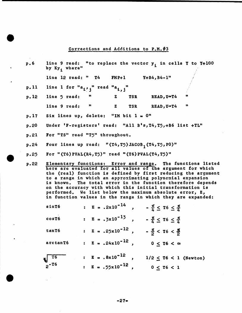
Corrections and Additions to P.M.#3 -----------~------------------------
p.6 line 9 read: "to replace the vector y1 in cells Y to Y+lOO by Kyi where"
p.11
p.17
p.20
p.21
p.24
p.25
p.22
line 12 read: " T4 FMP+l
line 5 read: II z
line 9 read: .. z TSR
TSR
Y+B4,B4·1"
R.EAD,U+T4
READ,U+T4
Six lines up, delete: "IM bit 1 • 0"
It
..
Under 'F-registers' read: "All B's,T4,T5,+B6 list +TL"
For "TS" read "T5" throughout.
Four lines up read: "(T4,T5)JACOB 1 (T4,T5,P0)"
For "(T6)PVAL(R4,T5)" read "(T6)PVAL(T4,T5)"
Elementary functions: Error and ran e. The functions listed here are evaluated or a 1 values o the argument for which the (real) function is defined by first reducing the argument to a range in which an appro~imating polynomial expansion is known. The total error in the function therefore depends on the accuracy with which this initial transformation is performed. We list below the maximum absolute error, E, in function values in the range in which they are expanded:
sinT6 . E = • 2x10· l 4 ,r < T6 < 1t . , 4 - - 4
cosT6 . E = .3x1o·l3 ,c < T6 < .! . , 4- - 4
tanT6 • E = .25x10· 12 JI< T6 < Jl • , 2 2
arctanT6 . E = .24x10· 12 0 < T6 < C)O . ,
" T6 • 8x10· 12 • E = 1/2 < T6 < 1 (Newton) . ,
2 ... T6 : E • .55x10· 12 , 0 < T6 < 1
•
•
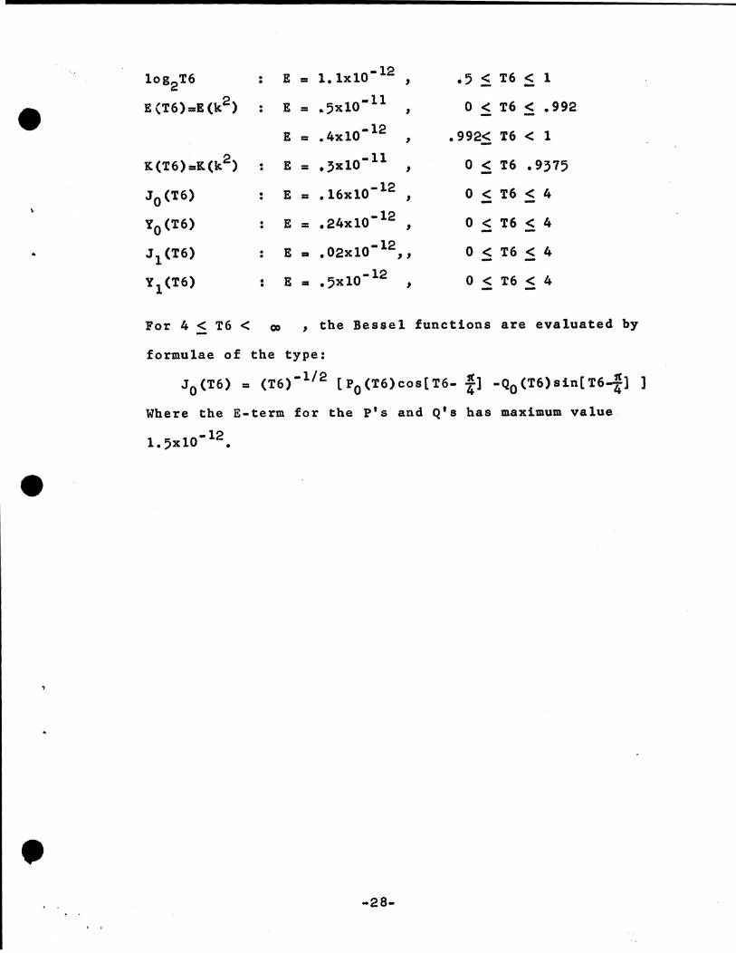
log2T6
E(T6)::rE(k2)
K(T6)aK(k2)
J 0 (T6)
t 0 (T6)
J l (T6)
Y l (T6)
:
• .
. •
• . • . • •
• •
E • 1. lxto• 12 ,
E = .5x1o•ll
E • .4xlo-12
E •• 3x10· 11
E = .16xl0-12 ,
E = .24xlo• 12 ,
0 -12 E • • 2xl0 , ,
E • .5x10- 12 ,
.5 < T6 < 1 - -0 < T6 < .992 - -
.992< T6 < 1 -0 < T6 .9375 -0 < T6 < 4
0 < T6 < 4 - -0 ~ T6 ~ 4
0 < T6 < 4 - -For 4 :f T6 < co , the Beseel functions are evaluated by
formulae of the type:
J 0 (T6) = (T6)· 112 [P0 (T6)cos[T6- fl -Q0 (T6)sin[T6-fl ]
Where the E-term for the P's and Q's has maximum value
-12 1. 5xl0 •
-28-