Embed Size (px)
Citation preview

Hoshizaki
“A Superior Degree of Reliability”
www.hoshizaki.com
ModelsDCM-750BAH-OSDCM-750BWH-OS
Cublet Ice Dispenser
Hoshizaki America, Inc.
Number: 71215Issued: 1-21-2003Revised: 5-5-2011
PARTS LIST

2
CONTENTSAuxiliary Codes ...................................................................................................................... 3Note About Ordering Parts .................................................................................................... 3Material Abbreviations ........................................................................................................... 4A. Ice Dispenser Assembly .................................................................................................... 5B. Refrigeration Circuit ........................................................................................................... 8
DCM-750BAH-OS ............................................................................................................. 8DCM-750BWH-OS .......................................................................................................... 10
C. Ice Making Unit ............................................................................................................... 12D. Water Circuit .................................................................................................................... 14E. Control Box Assembly...................................................................................................... 16F. Shutter Assembly ............................................................................................................. 18G. Gear Motor Assemblies ................................................................................................... 20H. Bin Assembly ................................................................................................................... 22J. Label Location .................................................................................................................. 24K. Accesories and Packaging .............................................................................................. 26

3
Auxiliary Codes
DCM-750BAH-OS N-0 January 2003 P-0 March 2004 P-1 August 2004 P-2 November 2004 Q-0 March 2005 R-0 April 2006 S-0 January 2007 T-0 January 2008 U-0 June 2009 U-1 September 2009 V-0 January 2010 V-1 May 2010 A-0 February 2011 A-1 TBD
DCM-750BWH-OS N-0 January 2003 P-0 September 2004 Q-1 December 2005 Q-2 August 2005 R-0 May 2006 S-0 June 2007 T-0 March 2008 U-1 December 2009 V-1 May 2010 A-0 TBD A-1 TBD
Auxiliary Code BreakdownThe auxiliary code is the first two characters in the serial number. The first character indicates the year. Years progress or regress in alphabetical order. The series runs from "A" through "V" and the letters "I" and "O" are skipped. The second character indicates significant part changes within a year. Base is "0" and this number advances for each change. In cases where there is a letter in parentheses, this designates the month. This is the last character in the serial number. The series runs from "(A)" through "(M)" and the letter "(I)" is skipped. This designation is only included when identifying a parts change within an auxiliary code.
Note About Ordering PartsMost assemblies cannot be ordered as complete units; parts in the assemblies generally must be ordered separately.

4
Material AbbreviationsALUMINUM AL = Aluminum
COPPER CU = Copper
PLASTIC ABS = Acrylonitrile -butadiene -styrene AC = Polyacetal EVA = Ethylene vinyl acetate PA = Polyamide = Nylon PC = Polycarbonate PE = Polyethylene PES = Polyester PETP = Polyethylene terephthalate = Tetlon PP = Polypropylene PS = Polystyrene PTFE = Polytetrafluoroethylene = Teflon PUR = Polyurethane PVC = Polyvinyl chloride
RUBBER VN = Vinyl Nitrile EPDM = EP rubber NBR = Nitrile butadiene rubber NR = Natural rubber NP = Neoprene SI.R = Silicone rubber SY.R = Synthetic rubber EPH = Epichlorohydrin
STEEL GS = Galvanized steel SS = Stainless steel PS = Plated steel PAS = Primed steel
5
A. Ice Dispenser AssemblyDCM-750BAH-OS, DCM-750BWH-OS
N-0 to A-1
33
11
32
7
6
7a8
9 9a10
12
13
1415
16
17
18 19
21
20
22
23
24
34
25
35
6a
28
37
29
3630
31
38
3940
41
42
44
43
27
26 27
39
12a
27a
37a
27a
3
54
1 2

6
Title: A. Ice Dispenser Assembly Model: DCM-750BAH-OS, DCM-750BWH-OS
Index No. Description
Material or Model Number Part Number
Required Number
N-0 to
P-1 P-2
Q-0 to
U-0
U-1 to
V-0
V-1 to
A-1
Ice Dispenser AssemblyOrder Assembly
Parts Individually
DCM-750BAH-OS 1A0747A01 1 -
1A0747A03 1 1 -
1A0747A05 1 -
1A2001A02 1DCM-750BWH-OS 1A0747A02 1 -
1A0747A04 1 1 -
1A0747A06 1 -
1A2002A02 1
1 Socket Head Cap Screw (fasteners for Ice Making Unit)
8×110, SS 7S12-0811 3 3 3 3 3
2 Split Lock Washer (fasteners for Ice Making Unit)
8, SS 7L22-0800 3 3 3 3 3
3 Thumbscrew (fasteners for Dispensing Motor)
415949G11 3 3 3 3 3
4 Thumbscrew (fasteners for Agitating Motor (L))
415949G11 4 4 4 4 4
5 Thumbscrew (fasteners for Agitating Motor (R))
415949G11 4 4 4 4 4
6 Evaporator Bracket 431738-01 1 1 1 1 1
6a Hex Head Bolt w/Washer (Lf) 5×12, SS 7B0230512 2 2 2 2 2
7 Spout 103932G01 1 1 1 1 1
7a Thumbscrew 415949G11 3 3 3 3 3
8 Spout Packing (A) 427195-01 1 1 1 1 1
9 Spout (B) 208807-01 1 1 1 1 1
9a Thumbscrew 415949G11 4 4 4 4 4
10 Spout Packing (B) 427196-01 1 1 1 1 1
11 Gasket 429758-01 3 3 3 3 3
12 Bin Cover 228433A01 1 1 1 1 1
12a Thumbscrew 415949G12 4 4 4 4 4
13 Collar 4H0171-01 2 2 2 2 2
14 Dispensing Auger 339194G01 1 1 1 1 1
15 Agitator (Right) 321013G01 1 1 1 1 1
16 Agitator (Left) 319017G02 1 1 1 1 1
17 Cup Guide 326702-01 2 2 2 2 2
18 Panel (Lower) 228436G01 1 1 1 1 1
19 Drip Tray 2A2591G02 1 1 1 1 1
20 Rear Panel DCM-750BAH-OS 228437-01 1 1 1 1 1DCM-750BWH-OS 228440-01 1 1 1 1 1
21 Side Panel (Left) DCM-750BAH-OS 2A2637-01 1 1 1 1 1DCM-750BWH-OS 2A2675-01 1 1 1 1 1
22 Side Panel (Right) DCM-750BAH-OS 2A2638-01 1 1 1 1 1DCM-750BWH-OS 2A2676-01 1 1 1 1 1
23 Top Panel 3A2526G01 1 1 1 1 1
24 Apron Panel 3A2529G01 1 1 -
3A3615G01 1 1 1
25 Water Sensor Assembly 4A2849G02 1 1 -
4A3753G02 1 1 1

7
Title: A. Ice Dispenser Assembly Model: DCM-750BAH-OS, DCM-750BWH-OS
Index No. Description
Material or Model Number Part Number
Required Number
N-0 to
P-1 P-2
Q-0 to
U-0
U-1 to
V-0
V-1 to
A-1
26 Ice Sensor Assembly 4A2849G01 1 1 -
4A3753G01 1 1 1
27 Sensor Cover 4A3848-01 2 2 2
27a Thumbscrew 415949G10 2 2 2
28 Front Panel Assembly 3A2854G01 1 1 1 -
2A2892-01 1 1
29 Grille 216100G01 1 1 1 1 1
30 "O" Ring 4A4755-05 1 1 1 1 1
31 Ring 431736-01 1 1 1 1 1
32 Strap 431737-01 1 1 1 1 1
33 Guide 211171-01 1 1 1 1 1
34 Packing 320668-01 1 1 1 1 1
35 Square Washer 433537-02 1 1 1 1 1
36 Grounding Screw 433304-02 1 1 1 1 1
37 Ice Chute 4A2204-02 1 1 1 1 1
37a Thumbscrew 415949G08 4 4 4 4 4
38 Spout Cover 215773-01 1 1 1 1 1
39 Louver DCM-750BAH-OS 103121-03 2 2 2 2 2
40 Air Filter DCM-750BAH-OS 208283G03 1 1 1 1 1
41 Middle Front Frame 2A2640G01 1 1 1 -
2A2890G01 1 1
42 Rocker Switch 4A1034-01 1 1 1 1 1
43 Rocker Switch 4A2957-01 1 1 1 1 1
44 Plunger Switch 4A5034-01 1 1 1 1 1

8
1a 1b 1c
8a
9a
B. Refrigeration CircuitDCM-750BAH-OS
N-0 to A-1
1
10
2 43 5
6
7
8
9
11 12
13
14
15 16
17
1817
V-0 and earlier
V-1 and later

9
Title: B. Refrigeration Circuit Model: DCM-750BAH-OS
Index No. Description
Material or Model Number Part Number
Required Number
N-0P-0
P-1 to
V-0 V-1A-0A-1
Refrigeration CircuitOrder Assembly Parts Individually
228430A02 1 1 -
2A5944A01 1 -
2A5944A02 1
1 Compressor RS55-C2E-CAA-219 4A1843-01 1 1 -RST55C1E-CAA-202 4A4376-01 1 1
1a Grommet 434403-01 4 4 -
4A2593-01 4 4
1b Spacer 434404-01 4 4 -
4A2595-01 4 4
1c Bolt 437889-01 4 4 4 4
2 Terminal Cover 4A1843F01 1 1 -
4A4376F01 1 1
3 Spring Clip 4A1843F02 1 1 -
4A4376F02 1 1
4 Protector 4A1877-01 1 1 -
4A2634-02 1 1
5 Protector Holder 4A1843F04 1 1 -
6 Condenser 3A0821-01 1 1 1 1
7 Shroud 340990-01 1 1 1 1
8 Fan Motor Bracket 3A0650-01 1 1 1 1
8a Hex Head Bolt w/Washer (Lf) 5×12, SS 7B0130512 4 4 4 4
9 Fan Motor 440911-01 1 -
4A3158-01 1 1 1
9a Self-Locking Nut 8-32 7N21I0832 4 4 4 4
10 Fan Blade 444898-01 1 1 1 1
11 Drier 4A1113-01 1 1 1 1
12 Drier Bracket 445847-01 1 1 -
Nylon Tie 8911-0301 1 1
13 Expansion Valve 4A1117-01 1 1 1 1
14 Expansion Valve Cover 4A1168-01 1 1 1 1
15 Clamp 443461-01 1 1 1 1
16 Expansion Valve Bulb Holder 3A0112-01 1 1 1 1
17 High-Pressure Switch 433441-07 1 1 -
463180-04 1 1
18 High-Pressure Switch Bracket 434938-01 1 1 -

10
B. Refrigeration CircuitDCM-750BWH-OS
N-0 to A-1
1716
V-0 and earlier
6a
4 5
6
7 2 3
13
12
10
11
8
9
1c1a 1b
14
1
15
18 19
16
V-1 and la
ter

11
Title: B. Refrigeration Circuit Model: DCM-750BWH-OS
Index No. Description
Material or Model Number Part Number
Required Number
N-0 to
U-1 V-1A-0 A-1
Refrigeration CircuitOrder Assembly Parts Individually
2A2460A01 1 -
2A5945A01 1 -
2A5945A02 1
1 Compressor RS55-C2E-CAA-219 4A1843-01 1 -RST55C1E-CAA-202 4A4376-01 1 1
1a Grommet 434403-01 4 -
4A2593-01 4 4
1b Spacer 434404-01 4 -
4A2595-01 4 4
1c Bolt 437889-01 4 4 4
2 Terminal Cover 4A1843F01 1 -
4A4376F01 1 1
3 Spring Clip 4A1843F02 1 -
4A4376F02 1 1
4 Protector 4A1877-01 1 -
4A2634-02 1 1
5 Protector Holder 4A1843F04 1 -
6 Water Cooled Condenser HS-0162 2A2359G03 1 1 1
6a Hex Head Bolt w/Washer (Lf) 5×12, SS 7B0130512 2 2 2
7 Drier 4A1113-01 1 1 1
8 Drier Bracket 445847-01 1 -
Nylon Tie 8911-0301 1 1
9 Expansion Valve 4A1117-01 1 1 1
10 Expansion Valve Cover 4A1168-01 1 1 1
11 Water Tube (A) 3A2134G01 1 1 1
12 Water Tube (B) 4A2646G01 1 1 1
13 Water Regulator 4A0911-04 1 1 1
14 Clamp 443461-01 1 1 1
15 Expansion Valve Bulb Holder 3A0112-01 1 1 1
16 High-Pressure Switch 433441-05 1 -
463180-05 1 1
17 High-Pressure Switch Bracket 434938-01 1 -
18 Male Connector 4A1087-01 1 1 1
19 Washer 4A0655-03 2 -
12
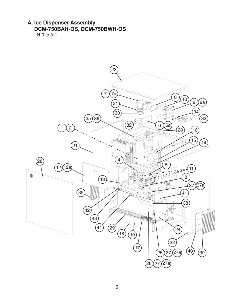
C. Ice Making UnitDCM-750BAH-OS, DCM-750BWH-OS N-0 to A-1
2a
1
8
2b
7
4a
3
7a
2
4
5
69
10
2c
7b
11

13
Title: C. Ice Making Unit Model: DCM-750BAH-OS, DCM-750BWH-OS
Index No. Description
Material or Model Number Part Number
Required Number
N-0 to
Q-0 (F)
Q-0 (G) to T-0 (A)
T-0 (B) to
V-0 (B)
V-0 (C) to
A-1
Ice Making Unit Order Assembly Parts Individually
324704A02 1 1 1 1
1 Gear Motor (for mounting hardware, see item 1 and 2 in "A. Ice Dispenser Assembly")
2U0077-01 1 1 1 1
2 Housing 315732G02 1 1 1 1
2a Hex Bolt 8×30, SS 7B02-0830 6 6 6 6
2b Plain Washer 7W22-0800 6 6 6 6
2c Spring Washer 7L22-0800 6 6 6 6
3 "O" Ring 4A4755-04 1 1 1 1
4 Extruding Head 2A1696G01 1 1 -
2A1594G01 1 1
4a Seal Bolt M10 474757G01 3 3 3 3
5 Cutter 315736G01 1 1 1 1
6 Auger 350941A01 1 1 1 1
7 Evaporator 228206G01 1 -
244336G01 1 1 -
244336G02 1
7a Socket Head Cap Screw 10×20, SS 7S12-1020 4 4 4 4
7b Split Lock Washer 10, SS 7L22-1000 4 4 4 4
8 Mechanical Seal 432493-01 1 1 1 1
9 Silicon Cord Heater 3U0097-01 1 1 1 1
10 Fiber Glass Tape L=800 4A2008L01 1 1 1
11 Flange 352714-01 1

14
27
28
26
2930
31
22
23
25
24
D. Water CircuitDCM-750BAH-OS, DCM-750BWH-OS N-0 to A-1
9
1
2
4
35
6
7
8
10
11
12
13
14
15
16
17
19
18
2021
23
15
18
31a

15
Title: D. Water Circuit Model: DCM-750BAH-OS, DCM-750BWH-OS
Index No. Description
Material or Model Number Part Number
Required Number
N-0 to
P-0
P-1 to
A-1
Water Circuit Order Assembly Parts Individually
2A1274A01 1 1
1 Water Supply Pipe 228452G01 1 1
2 Washer 4A0867-01 2 2
3 Water Valve (inlet and dispense)
4A0865-01 2 2
4 Drain Valve 4A2772-01 1 1
5 Inlet Water Valve Bracket (A) 454401-01 1 1
6 Drain Valve Bracket (B) 454402-01 1 -
4A3644-01 1
7 Dispense Water Valve Bracket (C)
4A0999-01 1 1
8 Reservoir Inlet 4A0869-01 1 1
9 Reservoir Bracket 340982-01 1 1
10 Reservoir Separator 4A1255-01 1 1
11 Reservoir 2A0753-01 1 1
12 Reservoir Cover 214810-01 1 1
13 Float Switch 435490-01 1 1
14 Drain Pan 323765G02 1 1
15 Fitting 4A0776G01 2 2
16 Tee 4A0525-04 1 1
17 Elbow 4A1016-01 1 1
18 Elbow 4A1017-01 2 2
19 Vinyl Hose L=120 7716-0913 1 1
20 Vinyl Hose L=70 7716-2025 1 1
21 Silicone Hose L=340 773013896 1 1
22 Vinyl Hose L=50 7725-1923 1 1
23 Vinyl Hose L=500 7725-1923 1 1
24 Vinyl Hose L=320 7725-2025 1 1
25 Vinyl Hose L=125 4A0658L01 1 1
26 Vinyl Hose L=445 4A0658L01 1 1
27 Water Supply Hose 428615-08 1 1
28 Vinyl Hose L=460 7725-1923 1 1
29 Vinyl Hose L=630 7725-1923 1 1
30 Drain Pipe 320836-01 1 1
31 Bracket 432496-01 1 1
31a Thumbscrew 415949G08 1 1
ClampsHose Clamp 4A2017-01 2 2
Hose Clamp 4A2017-02 2 2
Hose Clamp 4A2017-03 4 4
Hose Clamp 4A2017-08 4 4
Hose Clamp 4A2017-09 7 7
Hose Clamp 421642-04 1 1
Hose Clamp 435934-06 1 1
Hose Clamp 435934-07 1 1

16
22
23
24
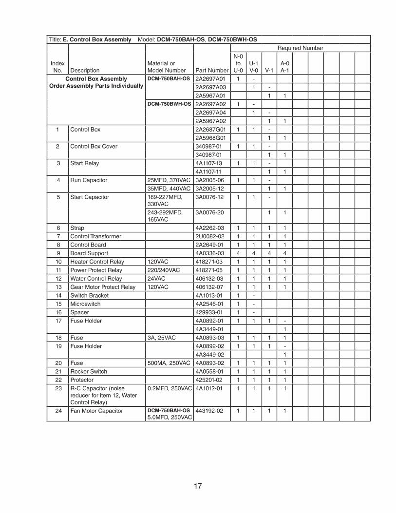
E. Control Box AssemblyDCM-750BAH-OS, DCM-750BWH-OS
N-0 to A-1
1
11
212
3
13
4
14
5
15
6
16
7
17 18
19
21
20
8 9
10
U-0 and earlier
U-1 and later
17
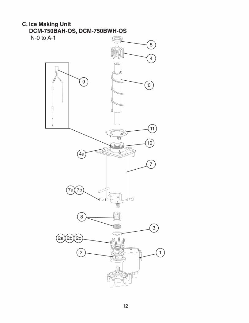
Title: E. Control Box Assembly Model: DCM-750BAH-OS, DCM-750BWH-OS
Index No. Description
Material orModel Number Part Number
Required Number
N-0 to
U-0U-1 V-0 V-1
A-0A-1
Control Box AssemblyOrder Assembly Parts Individually
DCM-750BAH-OS 2A2697A01 1 -
2A2697A03 1 -
2A5967A01 1 1DCM-750BWH-OS 2A2697A02 1 -
2A2697A04 1 -
2A5967A02 1 1
1 Control Box 2A2687G01 1 1 -
2A5968G01 1 1
2 Control Box Cover 340987-01 1 1 -
340987-01 1 1
3 Start Relay 4A1107-13 1 1 -
4A1107-11 1 1
4 Run Capacitor 25MFD, 370VAC 3A2005-06 1 1 -
35MFD, 440VAC 3A2005-12 1 1
5 Start Capacitor 189-227MFD, 330VAC
3A0076-12 1 1 -
243-292MFD, 165VAC
3A0076-20 1 1
6 Strap 4A2262-03 1 1 1 1
7 Control Transformer 2U0082-02 1 1 1 1
8 Control Board 2A2649-01 1 1 1 1
9 Board Support 4A0336-03 4 4 4 4
10 Heater Control Relay 120VAC 418271-03 1 1 1 1
11 Power Protect Relay 220/240VAC 418271-05 1 1 1 1
12 Water Control Relay 24VAC 406132-03 1 1 1 1
13 Gear Motor Protect Relay 120VAC 406132-07 1 1 1 1
14 Switch Bracket 4A1013-01 1 -
15 Microswitch 4A2546-01 1 -
16 Spacer 429933-01 1 -
17 Fuse Holder 4A0892-01 1 1 1 -
4A3449-01 1
18 Fuse 3A, 25VAC 4A0893-03 1 1 1 1
19 Fuse Holder 4A0892-02 1 1 1 -
4A3449-02 1
20 Fuse 500MA, 250VAC 4A0893-02 1 1 1 1
21 Rocker Switch 4A0558-01 1 1 1 1
22 Protector 425201-02 1 1 1 1
23 R-C Capacitor (noise reducer for item 12, Water Control Relay)
0.2MFD, 250VAC 4A1012-01 1 1 1 1
24 Fan Motor Capacitor DCM-750BAH-OS 5.0MFD, 250VAC
443192-02 1 1 1 1

18
F. Shutter AssemblyDCM-750BAH-OS, DCM-750BWH-OS
N-0 to A-1
1
11
2
12
3
13
4
14
5
156
16
7
17
8
18
9
19
10
20
89
9
10
10
18

19
Title: F. Shutter Assembly Model: DCM-750BAH-OS, DCM-750BWH-OS
Index No. Description
Material or Model Number Part Number
Required Number
N-0 to
A-1
Shutter AssemblyOrder Assembly Parts
Individually
2A0410A03
1 Truss Head Screw 4×8, SS 7C32-0408 2
2 Solenoid 3U0095-01 1
3 Solenoid Nut 429723-01 2
4 Solenoid Packing 430380-01 1
5 Packing Cover 431623-01 1
6 Truss Head Screw 4×12, SS 7C32-0412 4
7 Link 432232-01 1
8 Collar (D) 432471-01 2
9 Truss Head Screw 4×30, SS 7C32-0430 3
10 Self-Locking Nut 7N22-0400 3
11 Lever 3A1653G01 1
12 Collar (E) 432240-02 1
13 Spring 432878-01 1
14 R-C Capacitor 0.2MFD, 250VAC 4A1012-01 1
15 Truss Head Screw 4×8, SS 7C32-0408 1
16 Tooth Washer 7R22-0400 1
17 Hex Nut 7N11-0400 1
18 Plastic Sleeve Insert 432235-01 2
19 Shutter Base 2A2030-01 1
20 Shutter Base (B) 341011-01 1

20
G. Gear Motor AssembliesDCM-750BAH-OS, DCM-750BWH-OS N-0 to A-1
10
2
4
3
5
7
8
9
1
6

21
Title: G. Gear Motor Assemblies Model: DCM-750BAH-OS, DCM-750BWH-OS
Index No. Description
Material or Model Number Part Number
Required Number
N-0 to
P-1
P-2 to
A-1
Dispensing Motor AssemblyOrder Assembly Parts
Individually
453209A01 1 1
1 Gear Motor 2U0080-04 1 1
2 Joint 429764-01 1 1
3 Gear Motor Bracket (C3) (for mounting hardware, see item 3 in "A. Ice Dispenser Assembly")
340989-01 1 1
4 Plastic Sleeve 429761-01 1 1
Agitating Motor Assembly (L)Order Assembly Parts
Individually
454266A01 1 -
4A3669A01 1
5 Gear Motor 2U0099-01 1 -
4A3122-01 1
6 Gear Motor Bracket (L1) (for mounting hardware, see item 4 in "A. Ice Dispenser Assembly")
454407-01 1 -
4A3733-01 1
7 Plastic Sleeve 429761-01 1 1
Agitating Motor Assembly (R) Order Assembly Parts
Individually
454396A01 1 -
4A3670A01 1
8 Gear Motor 2U0099-01 1 -
4A3122-01 1
9 Gear Motor Bracket (R1) (for mounting hardware, see item 5 in "A. Ice Dispenser Assembly")
454409-01 1 -
4A3734-01 1
10 Plastic Sleeve 429761-01 1 1

22
H. Bin AssemblyDCM-750BAH-OS, DCM-750BWH-OS N-0 to A-1
10
8
2
43
5
6
77a
8a
9
1
11

23
Title: H. Bin Assembly Model: DCM-750BAH-OS, DCM-750BWH-OS
Index No. Description
Material or Model Number Part Number
Required Number
N-0 to
A-1
Bin AssemblyOrder Assembly Parts Individually
228432A01 1
1 Barrier 228453G01 1
2 Sliding Bracket 340986-01 1
3 "O" Ring 7616-P032 3
4 Shaft Holder 429818-01 3
5 Motor Barrier 340984-01 1
6 Bin Top 2A1713G01 1
7 Proximity Switch 4A2033-01 1
7a Thumbscrew 415949G08 2
8 Hinge 3A0762-01 1
8a Thumbscrew 415949G08 2
9 Actuator 208795G01 1
10 Shaft 412337-03 1
11 Snap Pin 715S-0004 1

24
1
2 3456
7
8
9
10
12
11
13
14
15
J. Label LocationDCM-750BAH-OS, DCM-750BWH-OS
N-0 to A-1
16

25
Title: J. Label Location Model: DCM-750BAH-OS, DCM-750BWH-OS
Index No. Description
Material or Model Number Part Number
Required Number
N-0 to
V-0
V-1 to
A-0 A-1
Label LocationOrder Assembly Parts
Individually
DCM-750BAH-OS 2A2684A01 1 1 1
DCM-750BWH-OS 2A2684A02 1 1 1
1 Ice-Water Label 4A2954-01 1 1 1
2 Label-Penguin-R 456246-01 1 1 1
3 Nameplate DCM-750BAH-OS 3A2565-01 1 -
3A6058-01 1 1DCM-750BWH-OS 3A2565-02 1 -
3A6058-02 1 1
4 Instruction Label 2A1646-01 1 1 -
5 Cleaning Label 2A0710-01 1 1 -
Maintenance Label 2A4562-01 1
6 Wiring Label 3A2567-01 1 -
3A5975-01 1 1
7 Switch Fuse Label 439962-01 1 1 1
8 Instruction Sheet 446463-01 1 1 1
9 Caution Label (J) 439149-01 1 1 -
Warning Label (J) 4A5114-01 1
10 Tag-Warning: Electrical Connection
435005-01 1 1 -
4A4766-01 1
11 Switch Label 4A1038-01 1 1 1
12 R404A Label 4A0960-01 1 1 1
13 Rating Label DCM-750BAH-OS 3A2566-01 1 -
3A6059-01 1 1DCM-750BWH-OS 3A2566-02 1 -
3A6059-02 1 1
14 Fuse Label (GM) 4A2835-01 1 1 1
15 Air Filter Label DCM-750BAH-OS 423177-01 1 1 1
16 Instruction Sheet 2A2704-01 1 -

26
Title: L. Accesories and Packaging Model: DCM-750BAH-OS, DCM-750BWH-OS
Index No. Description
Material or Model Number Part Number
Required Number
N-0 to
A-1
Instruction Manual 91A2EC10B 1
Packaging 1A0190G07 1
K. Accesories and PackagingDCM-750BAH-OS, DCM-750BWH-OS
N-0 to A-1