Embed Size (px)
Citation preview
>: Hands On Tutorial//
RC100 Seven Segment
HOT 01 v1.0 Page 1 of 23
>: 1 Introduction
This tutorial makes use of the seven segment displays on the Celoxica RC100 board to illustrate basic usage of DK1 and the Handel-C language.
>: 2 Requirements
DK1 must be installed on your computer. By default, these files are installed in the directory C:\Program Files\Celoxica\DK1. If these files have not been installed follow the setup procedures in the DK1 installation guide.
Xilinx Place and Route tools, a Celoxica RC100 board and Celoxica File Transfer Utility are required for the hardware implementations in the tutorial.
>: 3 Topics
• Setting up workspaces and projects in DK1 • The set clock directive • The Handel-C timing model – one clock cycle per assignment. • The Handel-C main function • Variables • Bit manipulation • Interface declarations and interfacing to hardware pins • Using the simulator
o View local variable and execution points o Viewing parallel threads o The watch window o Interfacing to simulator plugins o Setting breakpoints
• Creating EDIF netlists • The Xilinx P+R tools • Parallel execution in Handel-C using the par{} statement • The RC100 board and software • Creating Parallel hardware blocks • Channels • Using functions • Creating hardware libraries with DK1 • The standard library and some of its functions • Linking to external libraries with DK1 • DK1’s logic estimator tool • Creating and using RAMs and ROMs
>: Hands On Tutorial//
RC100 Seven Segment
HOT 01 v1.0 Page 2 of 23
>: 4 Creating and Setting up Workspaces and Projects
The DK1 design suite uses the concept of workspaces, projects and source files. A workspace can contain several projects, and a project can contain many source code files. DK1 workspaces have the file extension *.hw and DK1 projects have the extension *.hp.
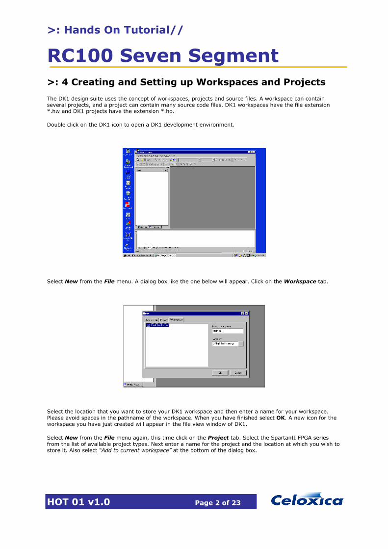
Double click on the DK1 icon to open a DK1 development environment.
Select New from the File menu. A dialog box like the one below will appear. Click on the Workspace tab.
Select the location that you want to store your DK1 workspace and then enter a name for your workspace. Please avoid spaces in the pathname of the workspace. When you have finished select OK. A new icon for the workspace you have just created will appear in the file view window of DK1.
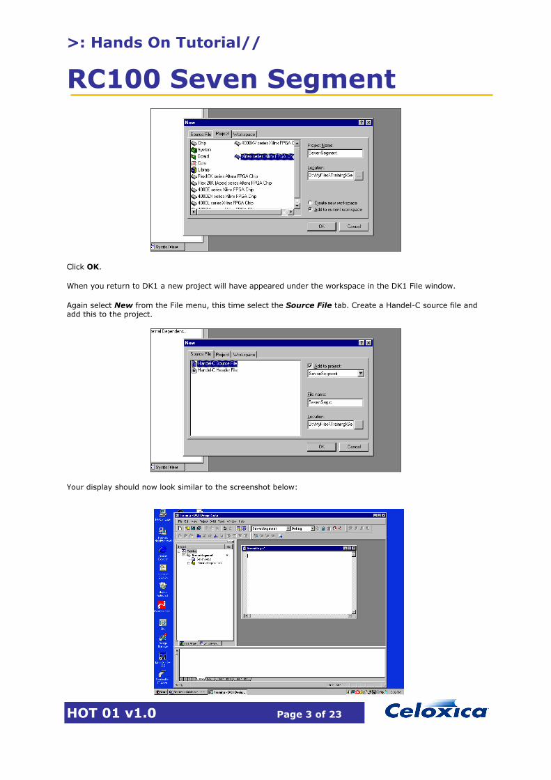
Select New from the File menu again, this time click on the Project tab. Select the SpartanII FPGA series from the list of available project types. Next enter a name for the project and the location at which you wish to store it. Also select “Add to current workspace” at the bottom of the dialog box.
>: Hands On Tutorial//
RC100 Seven Segment
HOT 01 v1.0 Page 3 of 23
Click OK.
When you return to DK1 a new project will have appeared under the workspace in the DK1 File window.
Again select New from the File menu, this time select the Source File tab. Create a Handel-C source file and add this to the project.
Your display should now look similar to the screenshot below:
>: Hands On Tutorial//
RC100 Seven Segment
HOT 01 v1.0 Page 4 of 23
>: 5 Seven Segment Display Tutorial
5.1 Introduction
This tutorial introduces many of the features and concepts of Handel-C through a simple design project. We are going to create, simulate and produce hardware for a simple counter that we will display on the seven-segment displays of the RC100 board. You will be asked to write some Handel-C code and debug it using the DK1 simulator. We will then turn this Handel-C design into an EDIF netlist, place and route it for the Celoxica RC100 board and run our designs on this board.
5.2 Building a Simple Counter
In this section we will write simple program that creates a binary counter and simulate this using the DK1 debugging environment.
5.2.1 Task 1 Create a new workspace and project as described in the previous section. Create a source file called SevenSegment.c and enter the following code:
/* Set the clock source */ set clock = external_divide "A11" 4; /* The main function */ void main(void) { unsigned 4 Counter; /* Create an infinite loop */ do { /* Create a 0 - 15 counter */ Counter++; }while(1); }
This program creates a simple four bit counter that loops around forever. As in ANSI C, the main() function is the starting point of all Handel-C programs. We create a variable of type unsigned 4 – i.e. 4 bits wide and with a range of 0 – 15. This variable is then incremented by one every clock cycle in continuous loop. When it reaches the value 15 it will overflow and return to 0 from where the cycle continues.
The set clock directive identifies the clock source from which the design is to be clocked. This is usually an external pin on the FPGA but can also be some other internal signal. The external_divide statement tells the compiler that the signal from the clock source should be divided by some number to generate the internal clock for the design. In this case, the clock source is pin number A11 on the FPGA and we will divide this clock signal by a factor of 4.
As all Handel-C designs are synchronous, a clock source must be specified for all programs.
>: Hands On Tutorial//
RC100 Seven Segment
HOT 01 v1.0 Page 5 of 23
Now add a few delay statements after the line in which Counter is incremented. You code should now look something like this:
/* Create an infinite loop */ do { /* Create a 0 - 15 counter */ Counter++;
delay; delay;
}while(1);
A delay statement causes the program to wait for one clock cycle (or in other words do nothing for one cycle).
Let’s now observe the behavior of the design in simulation:
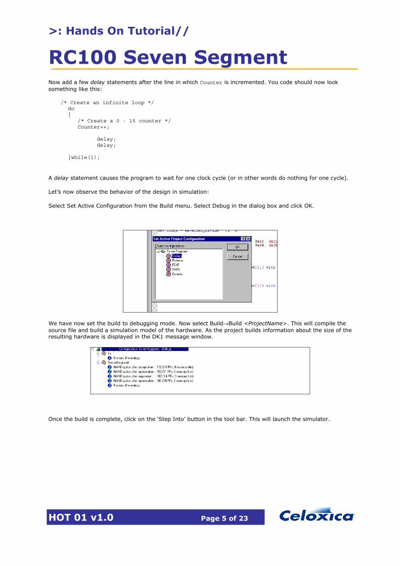
Select Set Active Configuration from the Build menu. Select Debug in the dialog box and click OK.
We have now set the build to debugging mode. Now select Build→Build <ProjectName>. This will compile the source file and build a simulation model of the hardware. As the project builds information about the size of the resulting hardware is displayed in the DK1 message window.
Once the build is complete, click on the ‘Step Into’ button in the tool bar. This will launch the simulator.

>: Hands On Tutorial//
RC100 Seven Segment
HOT 01 v1.0 Page 6 of 23
The yellow arrow in the source code shows the current execution point in the program. Use the ‘Step Into’ button to step through the design and observe the value of Counter changing. Verify that is loops around back to 0 after 15.
Experiment with setting a breakpoint on the line where Counter is incremented. Try typing the name of a variable into the ‘Watch’ window and viewing its value that way. Also observe the how the number of clock cycles is counted in the Clock/Thread window.
Once you have got a feel for how the simulator works, move on to the next section.
>: 6 Displaying the count on the seven segment display
In this section we will develop the counter design further and display the count on a 7-segment display. We will look at how one interfaces Handel-C designs to the outside world and simulate the 7-segment display with a simulator plugin before place and routing the design and running in on the RC100 board.
A block diagram of the design we are going to create is shown below:
Counter EncoderCounter[3:0] Segments[6:0]

>: Hands On Tutorial//
RC100 Seven Segment
HOT 01 v1.0 Page 7 of 23
The four bit output of the counter needs to be encoded so that the correct segments of the display light up for each number. The segments are numbered as follows, where segment 0 corresponds to the LSB and segment 6 to the MSB of the 7 bit word.
1
2
3
4
5
6
0
The encoder is best implemented as a 16 entry look-up table where the correct segment mask is returned for each number. We shall implement this look-up table as an on-chip ROM. This is done as follows using the rom keyword in Handel-C.
rom unsigned 7 NumberEncoder[16] = { 0x01, 0x4f, 0x12, 0x06, 0x4c, 0x24, 0x20, 0x0f, 0x00, 0x04, 0x08,0x60, 0x72, 0x42, 0x30, 0x38};
A ROM or a RAM can be treated just like an array in C with the exception that only ONE location in the ROM or RAM can be accessed at any one time. In an array all of the elements in the array can be accessed simultaneously because all the elements are independent hardware registers but in a ROM or RAM there is only one address and data port so it is only possible to retrieve one value at a time.
6.1.1 Task 2 Edit your code as follows:
• Remove the delay statements we added in the previous section. • Add the look-up table into the main() function of the design. We are going to use Counter as the
index to this table to retrieve the correct bit mask for the segments. • Create a new variable called SegmentOutput of the correct size and type and store the encoded result
in this. • Compile and simulate the code to check the correct values are returned.
We now need to connect SegmentOutput to the actual FPGA pins that are attached to the segments. This is done using the Handel-C interface specifier.
The interface specifier allows a Handel-C design to connect to external pins on the FPGA or to other blocks such as designs created using VHDL or EDIF modules generated using CoreGen.
The general syntax for an interface declaration is:
Interface <Type> (<Inputs>) <BusName> (<Outputs>) [ with { [ data = {<PinNames>}, ] [<…other modifiers>] } ];
To output to external pins we use the bus_out() statement:
interface bus_out() SegmentDisplay(SegmentOutput) with {data = {"V13", "AB14", "W14", "V17", "Y18", "W18", "AA20"}};
Add this inside the main() function of your code.

>: Hands On Tutorial//
RC100 Seven Segment
HOT 01 v1.0 Page 8 of 23
We also wish to be able to simulate the program before we place and route. We will use the 7-segment plugin dll supplied with DK1 to simulate the 7-segment display.
Add the following to the modifiers section of the interface declaration:
extlib = "7segment.dll", extinst = "Display0", extfunc = "PlugInSet"
The DK1 simulator is able to invoke external plugins. The ‘extlib’ parameter tells the simulator which plugin to call, the ‘extinst’ parameter specifies the instance of the plugin (it is possible to have several copies of a plugin running simultaneously) and the ‘extfunc’ parameter specifies which function inside the plugin dll should be called when something happens on the bus. For more information on the DK1 simulator API and how to write plugins please consult the DK1 documentation.
Your code should now look like this:
/* Set the clock source */ set clock = external_divide "A11" 4;
rom unsigned 7 NumberEncoder[16] = { 0x01, 0x4f, 0x12,0x06, 0x4c, 0x24, 0x20, 0x0f, 0x00, 0x04, 0x08,0x60, 0x72, 0x42, 0x30, 0x38}; /* The main function */ void main(void) { unsigned 4 Counter; unsigned 7 SegmentOutput; interface bus_out() SegmentDisplay(SegmentOutput) with {data = {"V13", "AB14", "W14", "V17", "Y18", "W18", "AA20"},
extlib = "7segment.dll", extinst = "Display0", extfunc = "PlugInSet"};
/* Create an infinite loop */ do { /* Create a 0 - 15 counter */ Counter++; SegmentOutput = NumberEncoder[Counter]; }while(1); }
We are now ready to simulate our design. Please ensure the 7-segment plugin (7-segment.dll) is located in the ‘Plugins’ folder of the DK1 directory (this should have been installed automatically with DK1).
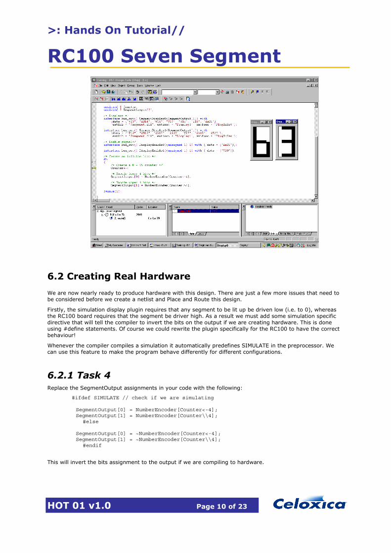
Make sure you are in ‘Debug’ mode and build the design. Once this is done click the ‘Step Into’ button on the tool bar to start debugging. A small window containing the simulated 7 segment display will appear. You may wish to resize the DK1 window so that the plugin window can also be seen.

>: Hands On Tutorial//
RC100 Seven Segment
HOT 01 v1.0 Page 9 of 23
Step through the program. You should see the showing the hexadecimal numbers 0 to F. Once you are sure that the design is working properly stop the simulation.
6.1.2 Task 3 Now extend your design so that we are using an 8-bit counter and two 7 segment displays to display the value. Use some of the Handel-C bit manipulation operators to split the 8-bit counter into the two 4-bit numbers to be encoded. Refer to the DK1 on-line documentation to find out more about the various bit manipulation operators available.
The pin numbers for the second display are:
Segment2[6..0] = W13, AB13, AA13, AA18, W17, AA19, AB20
The 7-segment displays on the RC100 board each have an enable signal that must be driven high in order for the display to work. Again we will use a bus_out() interface to drive the appropriate pins high.
interface bus_out() DisplayEnable0((unsigned 1) 1) with { data = {"AA22"}}; interface bus_out() DisplayEnable1((unsigned 1) 1) with { data = {"V20"}};
Simulate and debug the design until it works correctly. Once you have finished go on to the next section.
>: Hands On Tutorial//
RC100 Seven Segment
HOT 01 v1.0 Page 10 of 23
6.2 Creating Real Hardware
We are now nearly ready to produce hardware with this design. There are just a few more issues that need to be considered before we create a netlist and Place and Route this design.
Firstly, the simulation display plugin requires that any segment to be lit up be driven low (i.e. to 0), whereas the RC100 board requires that the segment be driver high. As a result we must add some simulation specific directive that will tell the compiler to invert the bits on the output if we are creating hardware. This is done using #define statements. Of course we could rewrite the plugin specifically for the RC100 to have the correct behaviour!
Whenever the compiler compiles a simulation it automatically predefines SIMULATE in the preprocessor. We can use this feature to make the program behave differently for different configurations.
6.2.1 Task 4 Replace the SegmentOutput assignments in your code with the following:
#ifdef SIMULATE // check if we are simulating SegmentOutput[0] = NumberEncoder[Counter<-4]; SegmentOutput[1] = NumberEncoder[Counter\\4];
#else SegmentOutput[0] = ~NumberEncoder[Counter<-4]; SegmentOutput[1] = ~NumberEncoder[Counter\\4];
#endif
This will invert the bits assignment to the output if we are compiling to hardware.
>: Hands On Tutorial//
RC100 Seven Segment
HOT 01 v1.0 Page 11 of 23
Secondly, there is a timing issue we need to consider. Our design will be running at 20 MHz, and it takes 3 clock cycles to do each increment of the counter. This means that the numbers on the displays will be changing at a rate of 6.6 MHz, which is far too fast for the human eye to see. We therefore need to add a delay into the loop so that the numbers are actually displayed long enough for us to see them.
A very efficient but not very accurate way of creating a delay is to create another counter and just increment it by one until it wraps around. We require a delay of about 1 second so a counter of size 24-bits will give a long enough delay ( 224 = 16,777,216 so at 20 MHz this will take about ¾ of a second to wrap around, which should be enough for us to see the number being displayed).
6.2.2 Task 5 Add this delay loop to the end of the main do…while() loop in the design. Once you have finished turn over the page.
6.3 Finished SevenSegment.c Program
/* Set the clock source */ set clock = external_divide "A11" 4; rom unsigned 7 NumberEncoder[16] = { 0x01, 0x4f, 0x12, 0x06, 0x4c,
0x24, 0x20, 0x0f, 0x00, 0x04, 0x08,0x60, 0x72, 0x42, 0x30, 0x38}; /* The main function */ void main(void) { unsigned 8 Counter; unsigned 7 SegmentOutput[2]; unsigned 24 Wait; /* Displays */ interface bus_out() SegmentDisplay0(SegmentOutput[0]) with {data = {"W13", "AB13", "AA13", "AA18", "W17", "AA19", "AB20"}, extlib = "7segment.dll", extinst = "Display1", extfunc = "PlugInSet"}; interface bus_out() SegmentDisplay1(SegmentOutput[1]) with {data = {"V13", "AB14", "W14", "V17", "Y18", "W18", "AA20"}, extlib = "7segment.dll", extinst = "Display0", extfunc = "PlugInSet"}; /* Enable signal*/ interface bus_out() DisplayEnable0((unsigned 1) 1) with { data = {"AA22"}}; interface bus_out() DisplayEnable1((unsigned 1) 1) with { data = {"V20"}}; /* Create an infinite loop */ do { /* Create a 0 - 15 counter */ Counter++; #ifdef SIMULATE // Check if we are simulating and encode approriately
SegmentOutput[0] = NumberEncoder[Counter<-4]; SegmentOutput[1] = NumberEncoder[Counter\\4];
>: Hands On Tutorial//
RC100 Seven Segment
HOT 01 v1.0 Page 12 of 23
#else
SegmentOutput[0] = ~NumberEncoder[Counter<-4]; SegmentOutput[1] = ~NumberEncoder[Counter\\4];
do { Wait++; }while(Wait != 0); #endif }while(1); }
We are now ready to create an EDIF netlist for this design. Select ‘Set Active Configuration’ from the ‘Build’ menu. Select EDIF in the dialog box.
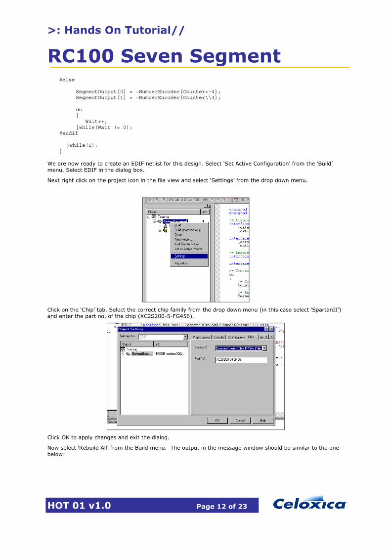
Next right click on the project icon in the file view and select ‘Settings’ from the drop down menu.
Click on the ‘Chip’ tab. Select the correct chip family from the drop down menu (in this case select ‘SpartanII’) and enter the part no. of the chip (XC2S200-5-FG456).
Click OK to apply changes and exit the dialog.
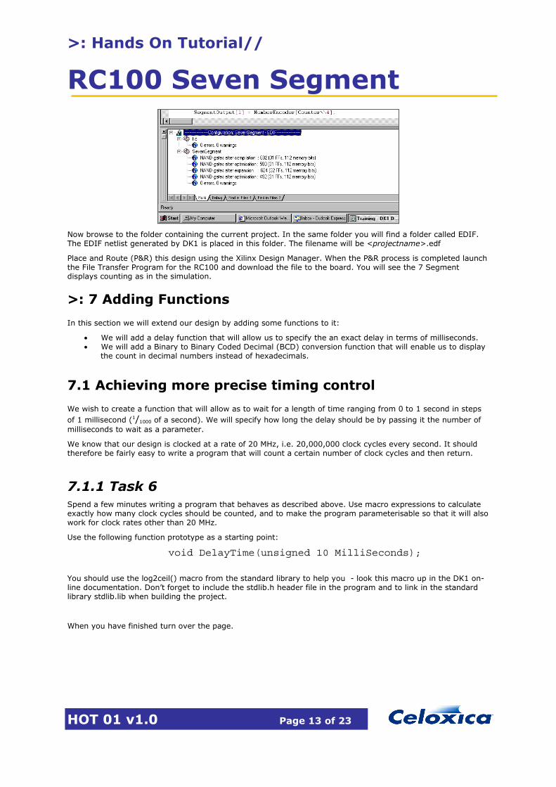
Now select ‘Rebuild All’ from the Build menu. The output in the message window should be similar to the one below:
>: Hands On Tutorial//
RC100 Seven Segment
HOT 01 v1.0 Page 13 of 23
Now browse to the folder containing the current project. In the same folder you will find a folder called EDIF. The EDIF netlist generated by DK1 is placed in this folder. The filename will be <projectname>.edf
Place and Route (P&R) this design using the Xilinx Design Manager. When the P&R process is completed launch the File Transfer Program for the RC100 and download the file to the board. You will see the 7 Segment displays counting as in the simulation.
>: 7 Adding Functions
In this section we will extend our design by adding some functions to it:
• We will add a delay function that will allow us to specify the an exact delay in terms of milliseconds. • We will add a Binary to Binary Coded Decimal (BCD) conversion function that will enable us to display
the count in decimal numbers instead of hexadecimals.
7.1 Achieving more precise timing control
We wish to create a function that will allow as to wait for a length of time ranging from 0 to 1 second in steps of 1 millisecond (1/1000 of a second). We will specify how long the delay should be by passing it the number of milliseconds to wait as a parameter.
We know that our design is clocked at a rate of 20 MHz, i.e. 20,000,000 clock cycles every second. It should therefore be fairly easy to write a program that will count a certain number of clock cycles and then return.
7.1.1 Task 6 Spend a few minutes writing a program that behaves as described above. Use macro expressions to calculate exactly how many clock cycles should be counted, and to make the program parameterisable so that it will also work for clock rates other than 20 MHz.
Use the following function prototype as a starting point:
void DelayTime(unsigned 10 MilliSeconds);
You should use the log2ceil() macro from the standard library to help you - look this macro up in the DK1 on-line documentation. Don’t forget to include the stdlib.h header file in the program and to link in the standard library stdlib.lib when building the project.
When you have finished turn over the page.
>: Hands On Tutorial//
RC100 Seven Segment
HOT 01 v1.0 Page 14 of 23
>: 8 Example DelayTime() function
#include "stdlib.h"
void DelayTime(unsigned 10 MilliSeconds) { macro expr ClockRate = 20000000; // Number of cycles per second macro expr MilliSecondCycles = ClockRate/1000; // Number of cycles/ms unsigned 10 i; unsigned (log2ceil(MilliSecondCycles)) Counter; // Wait for the number of milliseconds for(i = 0; i < MilliSeconds; i++) { Counter = MilliSecondCycles; do { Counter--; }while(Counter != 0); } }
In the example above we use a macro expression to calculate the number of clock cycles we have to wait for one millisecond to elapse. This value will change depending on the clock rate of the design. We then use the log2ceil() macro from the standard library to calculate exactly how wide the register we need to do the counting has to be. The log2ceil() macro returns the minimum number of bits necessary to represent a number.
We then use the for() loop to count the correct number of milliseconds.
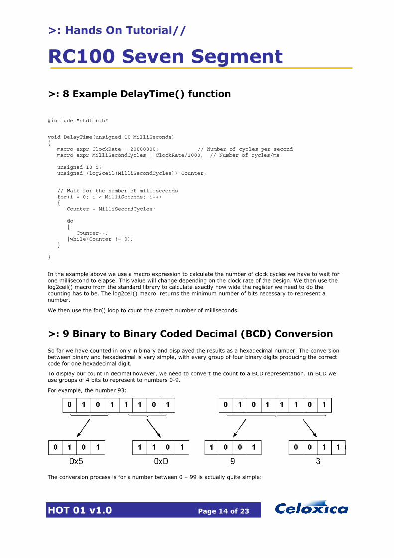
>: 9 Binary to Binary Coded Decimal (BCD) Conversion
So far we have counted in only in binary and displayed the results as a hexadecimal number. The conversion between binary and hexadecimal is very simple, with every group of four binary digits producing the correct code for one hexadecimal digit.
To display our count in decimal however, we need to convert the count to a BCD representation. In BCD we use groups of 4 bits to represent to numbers 0-9.
For example, the number 93:
The conversion process is for a number between 0 – 99 is actually quite simple:
>: Hands On Tutorial//
RC100 Seven Segment
HOT 01 v1.0 Page 15 of 23
1. Create 2 groups of 4 bits, called ‘tens’ and ‘ones’. 2. If then number is larger than 9 subtract 10 from it and add to 1 to the tens group. 3. Repeat step two until the remainder is <= 9 4. The remainder is the number of ones. 5. Concatenate the two 4 bit groups together and return the result.
Write a Handel-C function to implement this algorithm. Think about how to optimize the program to use as few clock cycles as possible. Hint: You may want to use Par{} to parallelise certain parts. Simulate the function if you want to.
Use the following prototype as a starting point:
unsigned 8 ConvertBinaryToBCD(unsigned 7 Number)
Once you have finished turn over the page.

>: Hands On Tutorial//
RC100 Seven Segment
HOT 01 v1.0 Page 16 of 23
>: 10 Example ConvertBinaryToBCD function
unsigned 8 ConvertBinaryToBCD(unsigned 7 Number) { unsigned 7 Ones; unsigned 7 Tens; par { Ones = Number; Tens = 0; } if(Ones > 99) { par { Ones = 9; Tens = 9; } } else { while(Ones > 9) { par { Ones = Ones - 10; Tens++; } }; } return (Tens<-4 @ Ones<-4); }
Now add the ConvertBinaryToBCD() and DelayTime() functions you have written to the SevenSegment.c design. Limit your counter to 0 – 99. Simulate the design, then Place and Route it and run it on the RC100 board.
Try experiment with different counting schemes, different delay values and getting the displays to flash while counting.
>: 11 Full code listing for seven segment program
/* Inculde standard header file */ #include "stdlib.h" set clock = external_divide "A11" 4; /* Prototypes */ void DelayTime(unsigned 10 MilliSeconds); unsigned 8 ConvertBinaryToBCD(unsigned 7 Number); /* The encoder rom */ rom unsigned 7 NumberEncoder[16] = { 0x01, 0x4f, 0x12,0x06, 0x4c, 0x24, 0x20, 0x0f, 0x00, 0x04, 0x08,0x60, 0x72, 0x42, 0x30, 0x38};

>: Hands On Tutorial//
RC100 Seven Segment
HOT 01 v1.0 Page 17 of 23
/* The main function */ void main(void) { unsigned 8 Counter, BCD; unsigned 7 SegmentOutput[2]; unsigned 24 wait; /* Displays */ interface bus_out() SegmentDisplay0(SegmentOutput[0]) with {data = {"W13", "AB13", "AA13", "AA18", "W17", "AA19", "AB20"}, extlib = "7segment.dll", extinst = "Display1", extfunc = "PlugInSet"}; interface bus_out() SegmentDisplay1(SegmentOutput[1]) with {data = {"V13", "AB14", "W14", "V17", "Y18", "W18", "AA20"}, extlib = "7segment.dll", extinst = "Display0", extfunc = "PlugInSet"}; /* Enable signal*/ interface bus_out() DisplayEnable0((unsigned 1) 1) with { data = {"AA22"}}; interface bus_out() DisplayEnable1((unsigned 1) 1) with { data = {"V20"}}; /* Create an infinite loop */ do { /* Create a 0 - 15 counter */ if(Counter == 99) { Counter = 0;} else { Counter++; } BCD = ConvertBinaryToBCD(Counter<-7); #ifdef SIMULATE /* Encode number to 7 segment display */ SegmentOutput[0] = NumberEncoder[BCD[3:0]]; SegmentOutput[1] = NumberEncoder[BCD[7:4]]; #else /* Encode number to 7 segment display */ SegmentOutput[0] = ~NumberEncoder[BCD[3:0]]; SegmentOutput[1] = ~NumberEncoder[BCD[7:4]]; /* Wait for 1 second */ DelayTime(1000); #endif }while(1); } void DelayTime(unsigned 10 MilliSeconds) { macro expr ClockRate = 20000000; // Number of cycles per second macro expr MilliSecondCycles = ClockRate/1000; // Number of cycles/ms unsigned 10 i; unsigned (log2ceil(MilliSecondCycles)) Counter; // Wait for the number of milliseconds for(i = 0; i < MilliSeconds; i++) {

>: Hands On Tutorial//
RC100 Seven Segment
HOT 01 v1.0 Page 18 of 23
Counter = MilliSecondCycles; do { Counter--; }while(Counter != 0); } } /* Binary to BCD conversion function */ unsigned 8 ConvertBinaryToBCD(unsigned 7 Number) { unsigned 7 Ones; unsigned 7 Tens; par { Ones = Number; Tens = 0; } if(Ones > 99) { par { Ones = 9; Tens = 9; } } else { while(Ones > 9) { par { Ones = Ones - 10; Tens++; } }; } return (Tens<-4 @ Ones<-4);
}
>: 12 Adding a Channel
We will now extend our design further and look at how channels can be used to allow parallel pieces of hardware to communicate. We will write a function that creates some hardware for generating a Fibonacii sequence and then pass the sequence we generate to the display hardware via a channel. We will base this design on the SevenSegment program we have just completed.
12.1 Channels
A channel allows two parallel processes to communicate. By using a 4 phase handshaking scheme it ensures that the data is transferred accurately from one processes to another, regardless of whether the processes are running at the same or different clock speeds. It takes one clock cycle in the slower of the two processes to transfer a value from one process to the other.
>: Hands On Tutorial//
RC100 Seven Segment
HOT 01 v1.0 Page 19 of 23
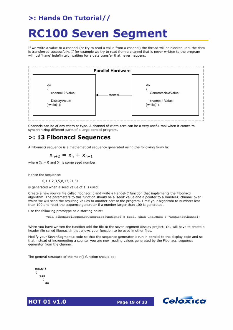
If we write a value to a channel (or try to read a value from a channel) the thread will be blocked until the data is transferred successfully. If for example we try to read from a channel that is never written to the program will just ‘hang’ indefinitely, waiting for a data transfer that never happens.
do{ GenerateNextValue;
channel ! Value;}while(1);
do{ channel ? Value;
DisplayValue;}while(1);
channel
Parallel Hardware
Channels can be of any width or type. A channel of width zero can be a very useful tool when it comes to synchronizing different parts of a large parallel program.
>: 13 Fibonacci Sequences
A Fibonacci sequence is a mathematical sequence generated using the following formula:
xn+2 = xn + xn+1
where X0 = 0 and X1 is some seed number.
Hence the sequence:
0,1,1,2,3,5,8,13,21,34, …
is generated when a seed value of 1 is used.
Create a new source file called fibonacci.c and write a Handel-C function that implements the Fibonacci algorithm. The parameters to this function should be a ‘seed’ value and a pointer to a Handel-C channel over which we will send the resulting values to another part of the program. Limit your algorithm to numbers less than 100 and reset the sequence generator if a number larger than 100 is generated.
Use the following prototype as a starting point:
void FibonacciSequenceGenerator(unsigned 8 Seed, chan unsigned 8 *SequenceChannel)
When you have written the function add the file to the seven segment display project. You will have to create a header file called fibonacii.h that allows your function to be used in other files.
Modify your SevenSegment.c code so that the sequence generator is run in parallel to the display code and so that instead of incrementing a counter you are now reading values generated by the Fibonacci sequence generator from the channel.
The general structure of the main() function should be:
main() { par
{ do
>: Hands On Tutorial//
RC100 Seven Segment
HOT 01 v1.0 Page 20 of 23
{ /* Display Code */ }while(1) do
{ /* Fibonacii Sequence Generator */ }while(1)
} }
Once you have finished turn over the page.
>: Hands On Tutorial//
RC100 Seven Segment
HOT 01 v1.0 Page 21 of 23
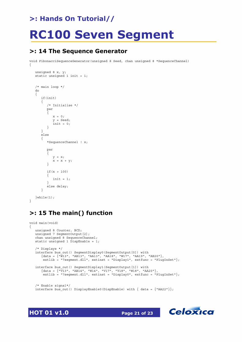
>: 14 The Sequence Generator
void FibonacciSequenceGenerator(unsigned 8 Seed, chan unsigned 8 *SequenceChannel) { unsigned 8 x, y; static unsigned 1 init = 1; /* main loop */ do { if(init) { /* Initialise */ par { x = 0; y = Seed; init = 0; } } else { *SequenceChannel ! x; par { y = x; x = x + y; } if(x > 100) { init = 1; } else delay; } }while(1); }
>: 15 The main() function
void main(void) { unsigned 8 Counter, BCD; unsigned 7 SegmentOutput[2]; chan unsigned 8 SequenceChannel; static unsigned 1 DispEnable = 1; /* Displays */ interface bus_out() SegmentDisplay0(SegmentOutput[0]) with {data = {"W13", "AB13", "AA13", "AA18", "W17", "AA19", "AB20"}, extlib = "7segment.dll", extinst = "Display1", extfunc = "PlugInSet"}; interface bus_out() SegmentDisplay1(SegmentOutput[1]) with {data = {"V13", "AB14", "W14", "V17", "Y18", "W18", "AA20"}, extlib = "7segment.dll", extinst = "Display0", extfunc = "PlugInSet"}; /* Enable signal*/ interface bus_out() DisplayEnable0(DispEnable) with { data = {"AA22"}};
>: Hands On Tutorial//
RC100 Seven Segment
HOT 01 v1.0 Page 22 of 23
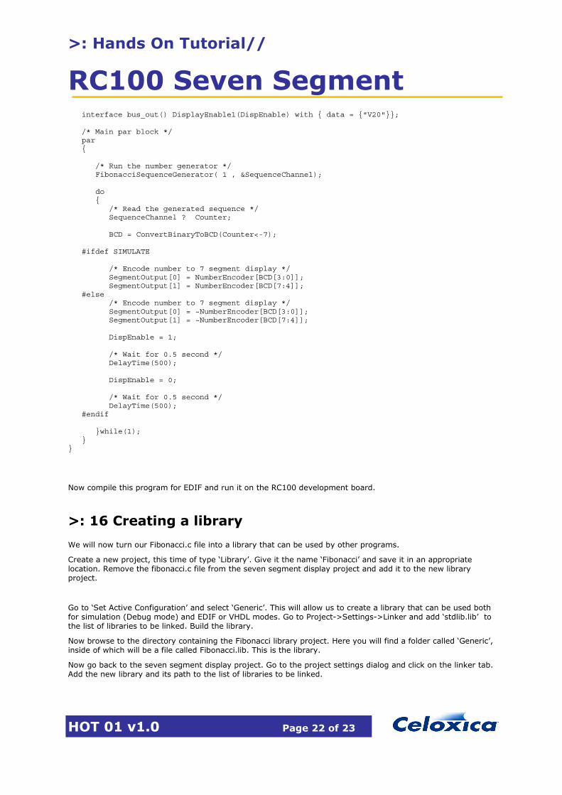
interface bus_out() DisplayEnable1(DispEnable) with { data = {"V20"}}; /* Main par block */ par { /* Run the number generator */ FibonacciSequenceGenerator( 1 , &SequenceChannel); do { /* Read the generated sequence */ SequenceChannel ? Counter; BCD = ConvertBinaryToBCD(Counter<-7); #ifdef SIMULATE /* Encode number to 7 segment display */ SegmentOutput[0] = NumberEncoder[BCD[3:0]]; SegmentOutput[1] = NumberEncoder[BCD[7:4]]; #else /* Encode number to 7 segment display */ SegmentOutput[0] = ~NumberEncoder[BCD[3:0]]; SegmentOutput[1] = ~NumberEncoder[BCD[7:4]]; DispEnable = 1; /* Wait for 0.5 second */ DelayTime(500); DispEnable = 0; /* Wait for 0.5 second */ DelayTime(500); #endif }while(1); } }
Now compile this program for EDIF and run it on the RC100 development board.
>: 16 Creating a library
We will now turn our Fibonacci.c file into a library that can be used by other programs.
Create a new project, this time of type ‘Library’. Give it the name ‘Fibonacci’ and save it in an appropriate location. Remove the fibonacci.c file from the seven segment display project and add it to the new library project.
Go to ‘Set Active Configuration’ and select ‘Generic’. This will allow us to create a library that can be used both for simulation (Debug mode) and EDIF or VHDL modes. Go to Project->Settings->Linker and add ‘stdlib.lib’ to the list of libraries to be linked. Build the library.
Now browse to the directory containing the Fibonacci library project. Here you will find a folder called ‘Generic’, inside of which will be a file called Fibonacci.lib. This is the library.
Now go back to the seven segment display project. Go to the project settings dialog and click on the linker tab. Add the new library and its path to the list of libraries to be linked.
>: Hands On Tutorial//
RC100 Seven Segment
HOT 01 v1.0 Page 23 of 23
Next click on the ‘Preprocessor’ tab and add the path of the fibonacci.h header file to the ‘Additional Include Paths’ box.
Build the project. DK1 should now use the library function.
>: 17 Further Information
For information on Celoxica products contact [email protected]. Regional office locations are given below.
Customer Support at [email protected] and +44 (0)1344 663649.
Celoxica Ltd. 20 Park Gate Milton Park Abingdon Oxfordshire OX14 4SH United Kingdom Tel: +44 (0) 1235 863 656 Fax: +44 (0) 1235 863 648
Celoxica, Inc 900 East Hamilton Avenue Campbell, CA 95008 USA Tel: +1 800 570 7004 Tel: +1 408 626 9070 Fax: +1 408 626 9079
Celoxica Japan KK YBP West Tower 11F 134 Godo-cho, Hodogaya-ku Yokohama 240-0005 Japan Tel: +81 (0) 45 331 0218 Fax: +81 (0) 45 331 0433
Celoxica Pte Ltd Unit #05-03 31 Int’l Business Park Singapore 609921 Tel: (65) 896 4838 Fax: (65) 566 9213
Copyright © 2001 Celoxica Ltd. All rights reserved. Celoxica and the Celoxica logo are trademarks of Celoxica Ltd. www.celoxica.com