Embed Size (px)
Citation preview
© Fraunhofer IESE
REQUIREMENTS ENGINEERINGLECTURE 2014/2015
Dr. Jörg Dörr
Conceptual Modelling
© Fraunhofer IESE
2
AGENDA
Standards & Templates Natural Language Requirements Specification with Conceptual Models Suitable Models for different Aspects
© Fraunhofer IESE
3
SPECIFICATION WITH CONCEPTUAL MODELS
Requirements Specification
© Fraunhofer IESE
4
Requirements Analysis as Part of Specification
Requirements Analysis is performed in order to analyze certain quality characteristics of requirements
Is Requirements Analysis then synonym to requirements V&V? No! Analysis is concerned with an incomplete set of requirements,
not discussed by the stakeholder. Requirements Analysis can be a very early activity.
Requirements validation should have a complete, agreed upon set of requirements as input. Therefore, it is also regarded as part of the specification.
© Fraunhofer IESE
5
Means for Requirements Analysis
Analysis Checklists Conceptual Modeling
© Fraunhofer IESE
6
Requirements Analysis Checklists – Typical Questions (1)
Is the requirement adequate with the business goal of the project? Does the requirement conflict with some domain constraint, policies
or regulation? Does the requirement include premature design or implementation
information? Is the requirement necessary? Does the requirement require non-standard hardware or must
software be used? Is the requirement ambiguous, could different persons read it in
different ways? What are the different interpretations for the requirement? Is the requirement realistic given the technology that will used to
implement the system?
© Fraunhofer IESE
7
Requirements Analysis Checklists – Typical Questions (2)
Does the description of a requirement describe a single requirement or could it be broken into several different requirements?
Has each requirement been assigned a priority? Are the system boundaries well defined? Have the portability, reliability, usability and maintainability
requirements for the system been respected? Did you develop a behavioral or structural model for the system? Is the Data Dictionary implemented and correctly updated? Is the requirement testable by the test engineers?
© Fraunhofer IESE
8
Conceptual Modeling
Conceptual Modeling is performed by the requirements engineer (analyst) to understand the problem domain and the requirements.
Various models can be created to find out whether a problem domain or the requirements are understood well, i.e., whether the understanding of the requirements engineer is complete, consistent, and correct: Goals Data Interaction Structure …
Note: The models created during conceputal modeling are not necessarily part of the requirements specification. But they can be part of the requirements specification.
© Fraunhofer IESE
9
Conceptual Models
For the different models, also various notations can be used, e.g., i-star (i*) E/R Diagrams UML SysML Business Process Modelling Notations …
© Fraunhofer IESE
10
Goal Modeling – Definitions
Goal Models are often the first models used as they are on a high abstraction level.
Definition goal: “A goal is a desirable state lying in the future, which is not
reached automatically but by specific actions.” Goals and their dependencies are often described in conceptual
models that are based on modelling languages. Definition goal model: “A goal model is a conceptual model. Its
goals and decompositions are documented in sub-goals and as necessary further dependencies between (sub)-goals.“
© Fraunhofer IESE
11
Goal Modeling: Why should one do goal modeling?
Goals can be one of the very early starting points (besides current problems) for requirements elicitation
Goals are a fundamental concept to understand why new software or systems or changes to these systems are needed
Goal modeling can be the anchor (rationale) for the following requirements traceability from high level to lower level
© Fraunhofer IESE
12
Classification of Goals
Subject that has a goal Organizations or organizational units Individual Persons or Roles
Object affected by the goal Quality goals Functional goals
© Fraunhofer IESE
13
Representation of Goals
Various notations exist for goal modeling i-star (i*) GRL SIG (Softgoal interdependency graphs) And / OR – Trees Just text …
© Fraunhofer IESE
14
i*-FrameworkI*-Framework
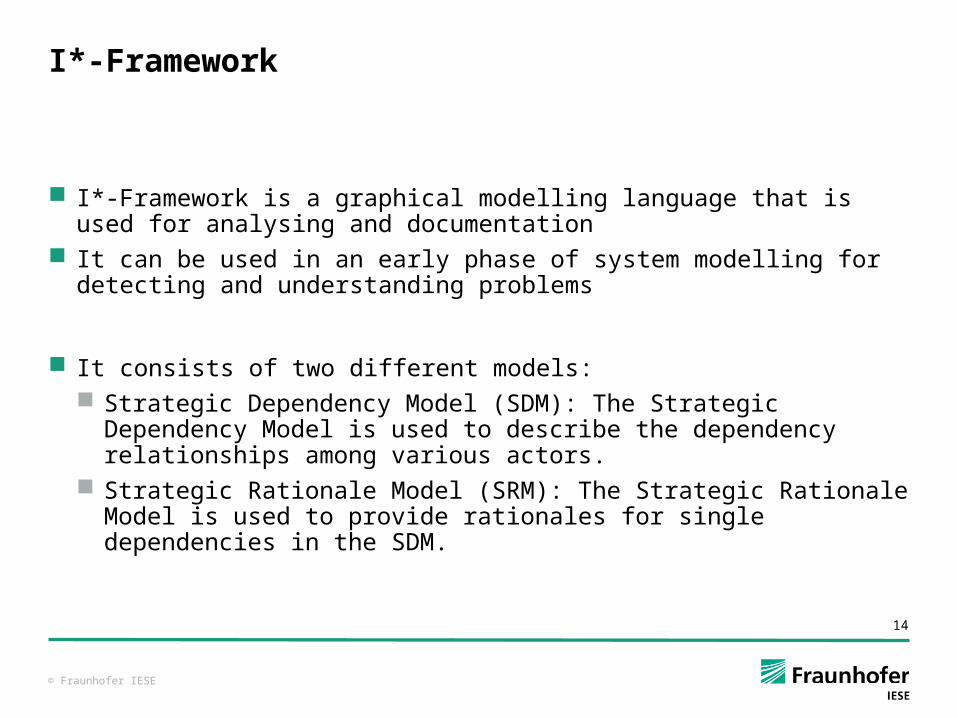
I*-Framework is a graphical modelling language that is used for analysing and documentation
It can be used in an early phase of system modelling for detecting and understanding problems
It consists of two different models: Strategic Dependency Model (SDM): The Strategic Dependency
Model is used to describe the dependency relationships among various actors.
Strategic Rationale Model (SRM): The Strategic Rationale Model is used to provide rationales for single dependencies in the SDM.
© Fraunhofer IESE
15
Objects in i*
Actor
Actor Boundary
Resource
Softgoal
Goal
Task
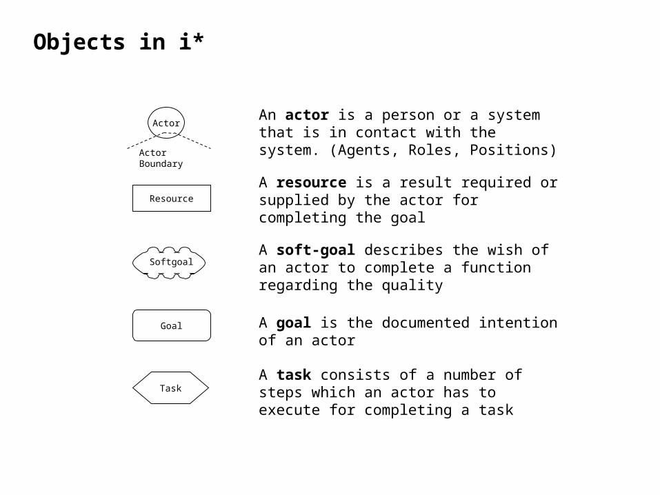
An actor is a person or a system that is in contact with the system. (Agents, Roles, Positions)
A resource is a result required or supplied by the actor for completing the goal
A soft-goal describes the wish of an actor to complete a function regarding the quality
A goal is the documented intention of an actor
A task consists of a number of steps which an actor has to execute for completing a task
Objects in i*
© Fraunhofer IESE
16
Connections in i*
Soft-goal Dependency
D D
Goal Dependency
D D
Task Dependency
D D
Resource Dependency
D D
Depender Dependee
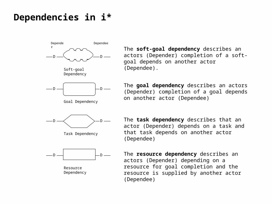
The goal dependency describes an actors (Depender) completion of a goal depends on another actor (Dependee)
The task dependency describes that an actor (Depender) depends on a task and that task depends on another actor (Dependee)
The soft-goal dependency describes an actors (Depender) completion of a soft-goal depends on another actor (Dependee).
The resource dependency describes an actors (Depender) depending on a resource for goal completion and the resource is supplied by another actor (Dependee)
Dependencies in i*
© Fraunhofer IESE
17
Connections in i*
Means-end-Link
Task-Decomposition-Link
+/-
Contribution-Link
+ pos. affected
- neg. affected
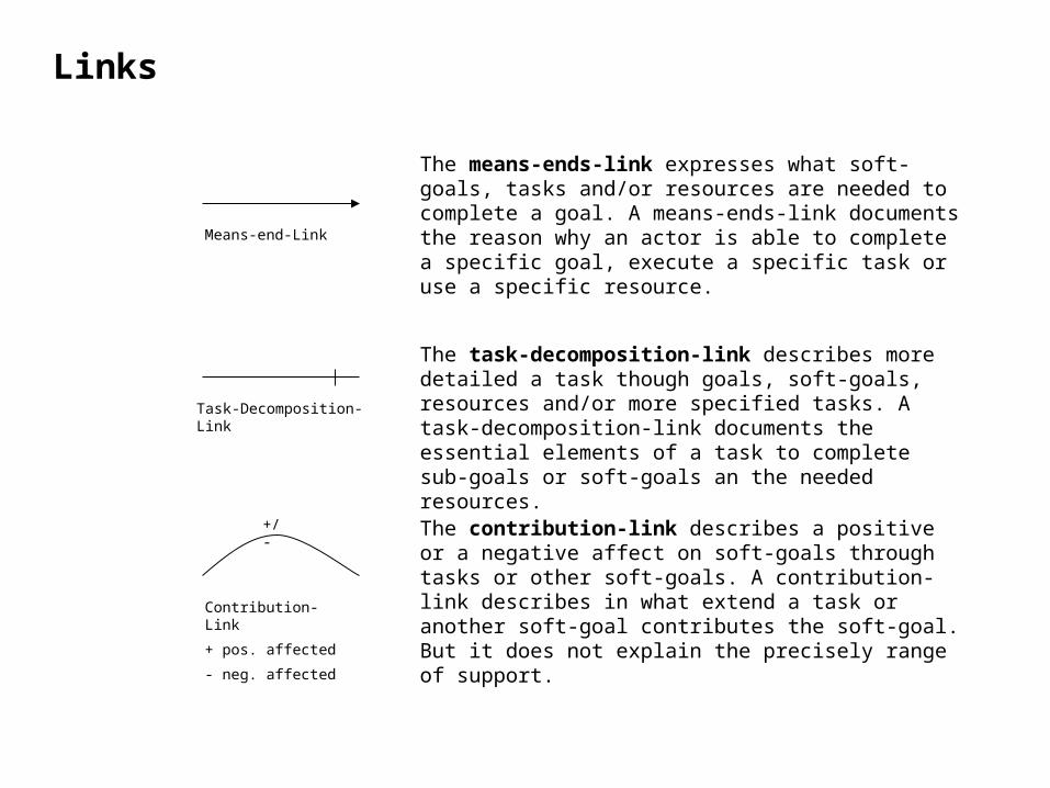
The means-ends-link expresses what soft-goals, tasks and/or resources are needed to complete a goal. A means-ends-link documents the reason why an actor is able to complete a specific goal, execute a specific task or use a specific resource.
The contribution-link describes a positive or a negative affect on soft-goals through tasks or other soft-goals. A contribution-link describes in what extend a task or another soft-goal contributes the soft-goal. But it does not explain the precisely range of support.
The task-decomposition-link describes more detailed a task though goals, soft-goals, resources and/or more specified tasks. A task-decomposition-link documents the essential elements of a task to complete sub-goals or soft-goals an the needed resources.
Links
© Fraunhofer IESE
18
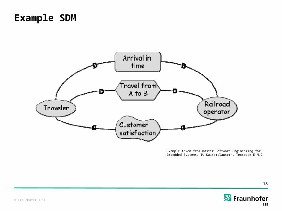
Example SDM
Example taken from Master Software Engineering for Embedded Systems, TU Kaiserslautern, Textbook E-M.2
© Fraunhofer IESE
19
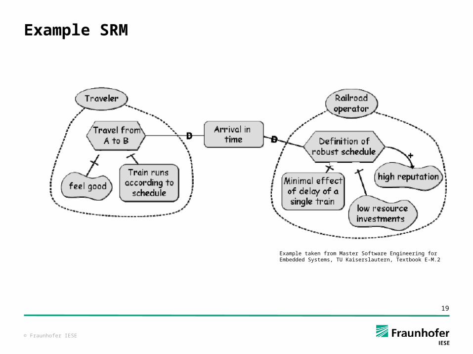
Example SRM
Example taken from Master Software Engineering for Embedded Systems, TU Kaiserslautern, Textbook E-M.2
© Fraunhofer IESE
20
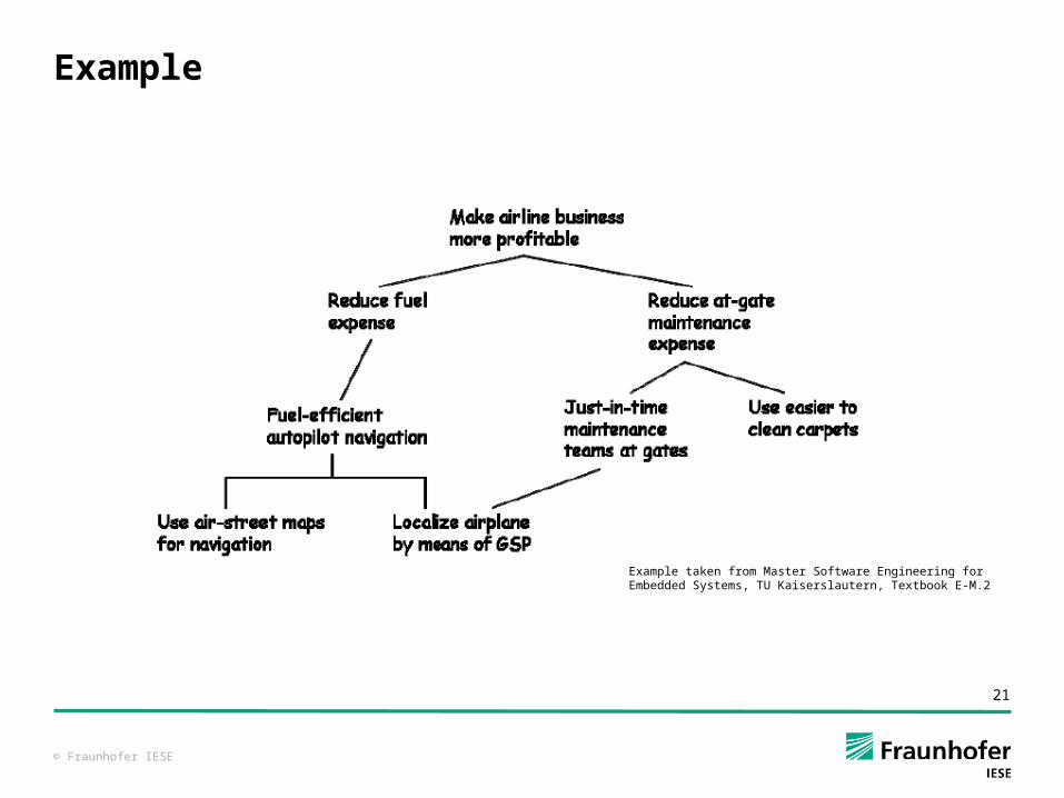
And / OR Decompositions (Trees)
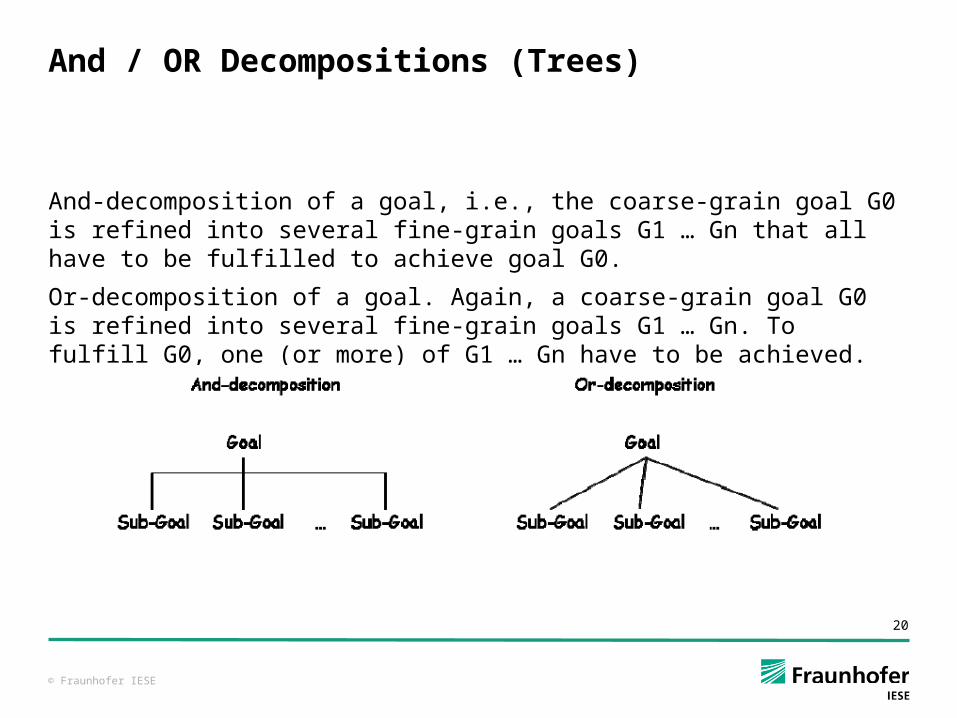
And-decomposition of a goal, i.e., the coarse-grain goal G0 is refined into several fine-grain goals G1 … Gn that all have to be fulfilled to achieve goal G0.
Or-decomposition of a goal. Again, a coarse-grain goal G0 is refined into several fine-grain goals G1 … Gn. To fulfill G0, one (or more) of G1 … Gn have to be achieved.
© Fraunhofer IESE
21
Example
Example taken from Master Software Engineering for Embedded Systems, TU Kaiserslautern, Textbook E-M.2
© Fraunhofer IESE
23
Usage of UML for Conceptual Modeling (1)
Various Diagrams of the UML can be used for Requirements Analyis, e.g.: Activity Diagrams for business processes / workflows Class and Object Diagrams for modeling data User Interface Navigation Maps, Collaboration Diagrams, and
Sequence Diagrams for Interaction between different systems and stakeholders and systems
© Fraunhofer IESE
24
Usage of UML for Conceptual Modeling (2)
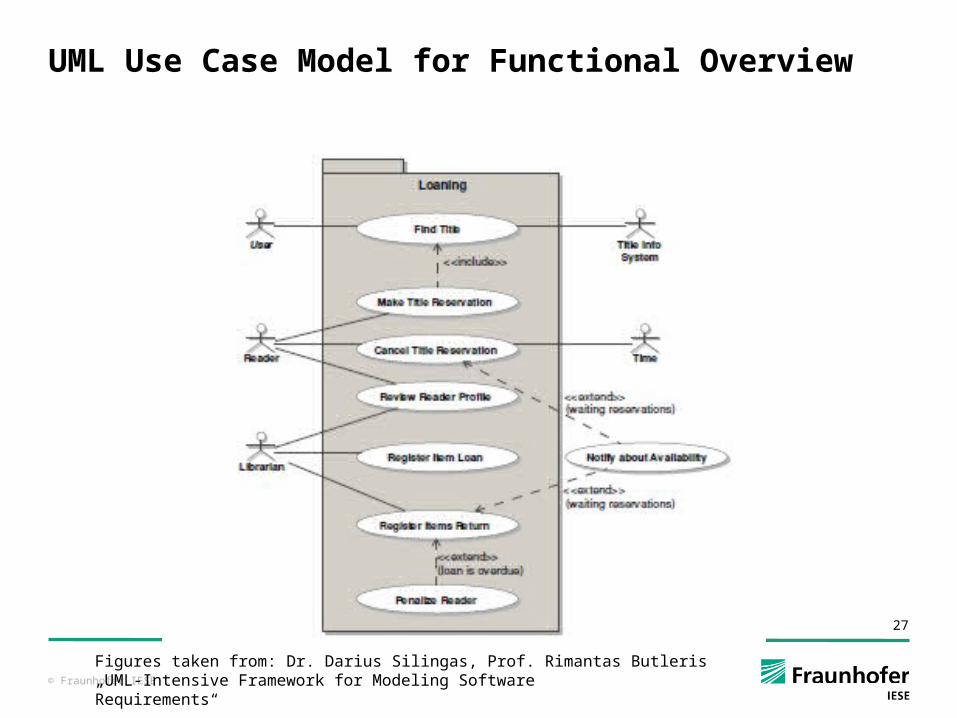
Use Case Diagrams for getting an overview on the system functionality
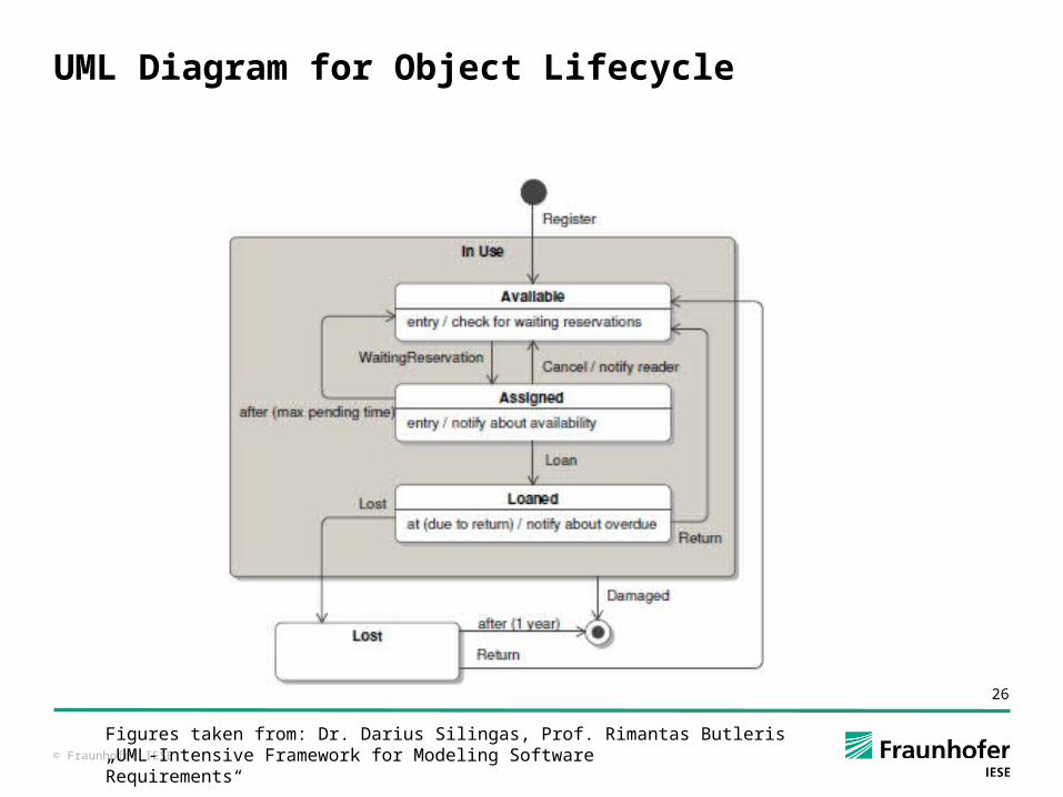
State Diagrams for modeling intended system states and their transformation or the (business) object lifecycles
…
© Fraunhofer IESE
25
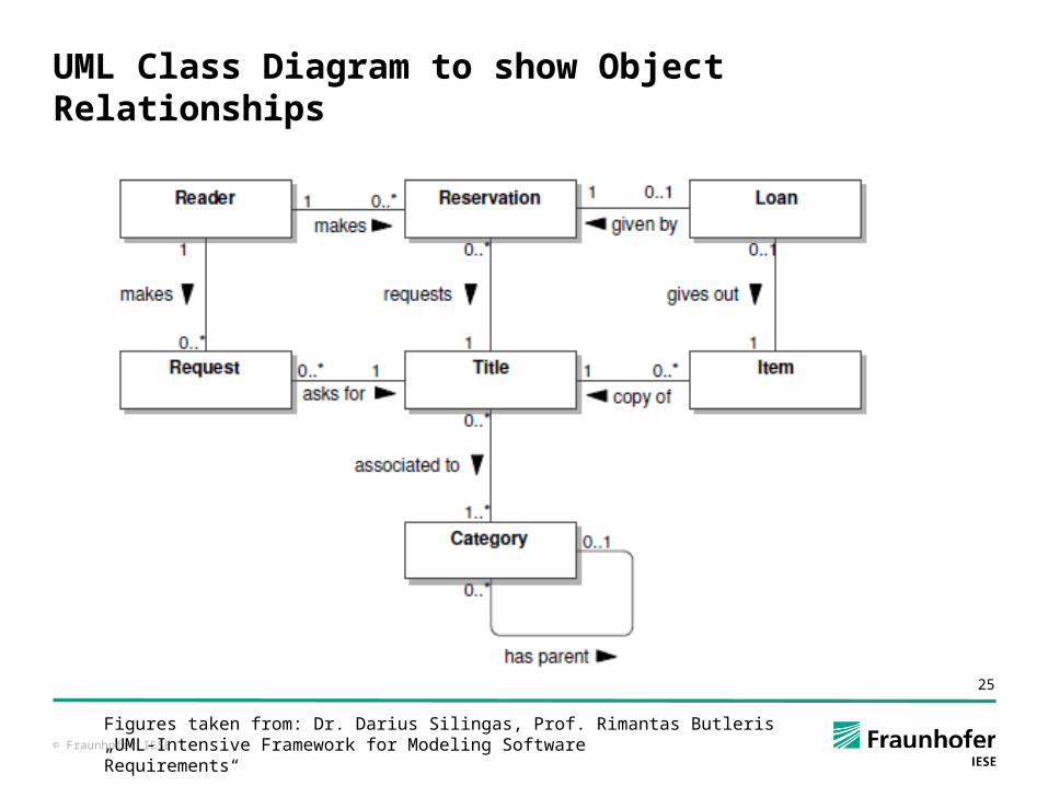
UML Class Diagram to show Object Relationships
Figures taken from: Dr. Darius Silingas, Prof. Rimantas Butleris„UML-Intensive Framework for Modeling SoftwareRequirements“
© Fraunhofer IESE
26
UML Diagram for Object Lifecycle
Figures taken from: Dr. Darius Silingas, Prof. Rimantas Butleris„UML-Intensive Framework for Modeling SoftwareRequirements“
© Fraunhofer IESE
27
UML Use Case Model for Functional Overview
Figures taken from: Dr. Darius Silingas, Prof. Rimantas Butleris„UML-Intensive Framework for Modeling SoftwareRequirements“
© Fraunhofer IESE
28
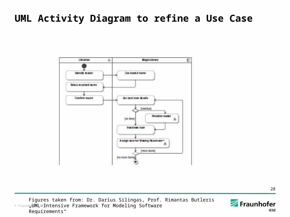
UML Activity Diagram to refine a Use Case
Figures taken from: Dr. Darius Silingas, Prof. Rimantas Butleris„UML-Intensive Framework for Modeling SoftwareRequirements“
© Fraunhofer IESE
29
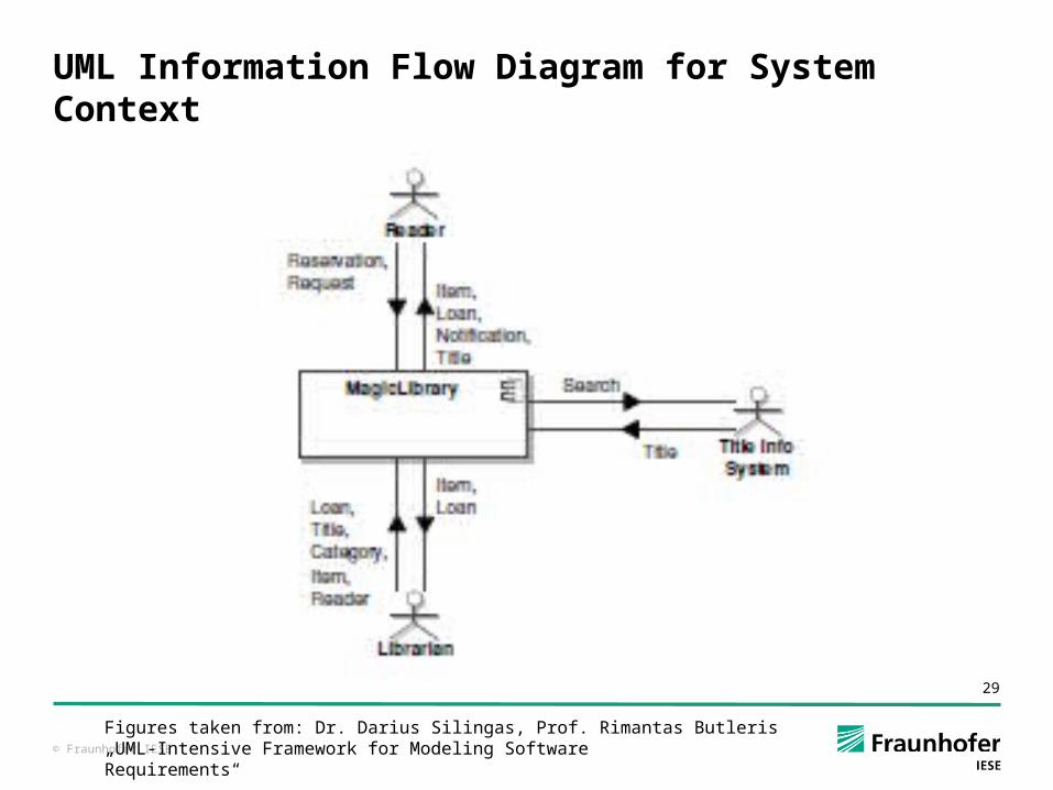
UML Information Flow Diagram for System Context
Figures taken from: Dr. Darius Silingas, Prof. Rimantas Butleris„UML-Intensive Framework for Modeling SoftwareRequirements“
© Fraunhofer IESE
30
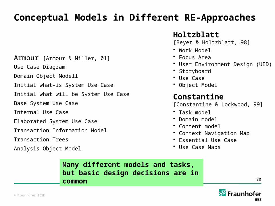
Conceptual Models in Different RE-Approaches
Armour [Armour & Miller, 01]
Use Case Diagram
Domain Object Modell
Initial what-is System Use Case
Initial what will be System Use Case
Base System Use Case
Internal Use Case
Elaborated System Use Case
Transaction Information Model
Transaction Trees
Analysis Object Model
Many different models and tasks, but basic design decisions are in common
Holtzblatt [Beyer & Holtzblatt, 98]• Work Model• Focus Area• User Environment Design (UED)• Storyboard• Use Case• Object Model
Constantine [Constantine & Lockwood, 99]• Task model• Domain model• Content model• Context Navigation Map• Essential Use Case• Use Case Maps
© Fraunhofer IESE
31
Conceptual Models Summary
Conceptual models help clarifying certain aspects of a system in more detail than just natural language Support requirements analysis
For different aspects of a system, different notations can be used
© Fraunhofer IESE
32
SUITABLE MODELS FOR DIFFERENT ASPECTS
Requirements Specification
© Fraunhofer IESE
33
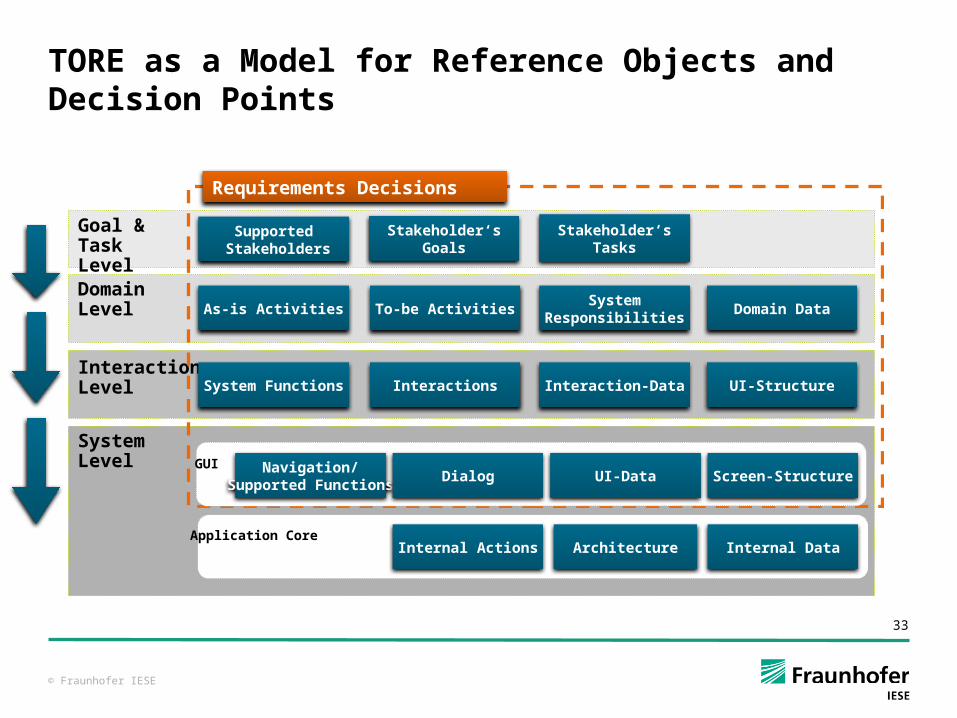
TORE as a Model for Reference Objects and Decision Points
Supported Stakeholders
Goal & Task LevelDomain Level
InteractionLevel
As-is Activities To-be ActivitiesSystem
ResponsibilitiesDomain Data
System Functions Interactions Interaction-Data UI-Structure
System Level
Requirements Decisions
Internal Actions Internal DataArchitectureApplication Core
Screen-StructureNavigation/
Supported FunctionsDialog UI-Data
GUI
Stakeholder‘sGoals
Stakeholder‘sTasks
© Fraunhofer IESE
34
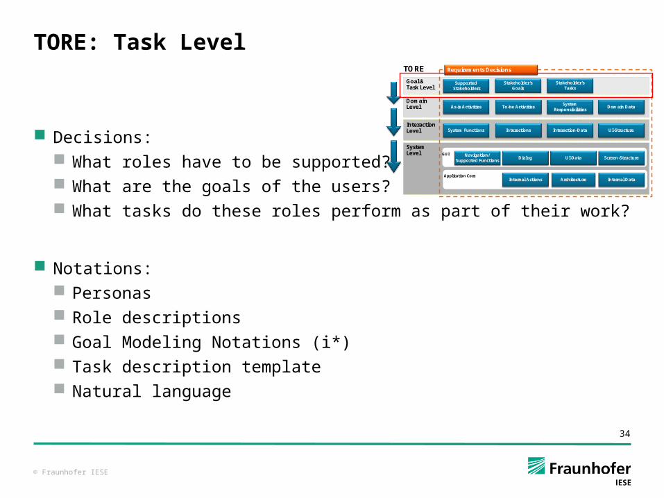
TORE: Task Level
Decisions: What roles have to be supported? What are the goals of the users? What tasks do these roles perform as part of their work?
Notations: Personas Role descriptions Goal Modeling Notations (i*) Task description template Natural language
TORE
SupportedStakeholdersSupported
Stakeholders
Goal & Task Level
Domain Level
InteractionLevel
As-is ActivitiesAs-is Activities To-be ActivitiesTo-be ActivitiesSystem
ResponsibilitiesSystem
ResponsibilitiesDomain DataDomain Data
System FunctionsSystem Functions InteractionsInteractions Interaction-DataInteraction-Data UI-StructureUI-Structure
System Level
Requirements DecisionsRequirements Decisions
Internal ActionsInternal Actions Internal DataInternal DataArchitectureArchitectureApplication Core
Screen-StructureScreen-StructureNavigation/
Supported FunctionsNavigation/
Supported FunctionsDialogDialog UI-DataUI-Data
GUI
Stakeholder‘sGoals
Stakeholder‘sGoals
Stakeholder‘sTasks
Stakeholder‘sTasks
© Fraunhofer IESE
35
How to Describe the Users (1)?
A user role is an abstract summary of needs, interests, expectations, behavior, and responsibilities that are characteristic for a set of future system users [according to Constantine/Lockwood99].
A user profile describes the knowledge and the skills of typical users.
Can be elicited by asking the users asking surrogate users (marketing, sales, hotline, trainer) examining documents in the business process
© Fraunhofer IESE
36
How to Describe the Users (2)?
Role Description Responsibilities Success criteria Tasks Communication partners Degree of innovation
User Profile: Knowledge/experience/skills regarding tasks regarding software system
© Fraunhofer IESE
37
Example: Counter Employee in University Library (1)
Role Description Responsibility: taking care of readers, issuing books Success criteria: reader satisfaction, book inventory up to date Tasks: advice, issue, return, registration, cancellation Communication partners: readers, librarians Degree of innovation: low
© Fraunhofer IESE
38
Example: Counter Employee in University Library (2)
User Profile Prior knowledge of library tasks:
Books: must be sufficient for advice Library workflows: often low, since student assistant
Prior knowledge of software: Often low, since usually humanities student
© Fraunhofer IESE
39
Further Possibility: Description of “Personas”
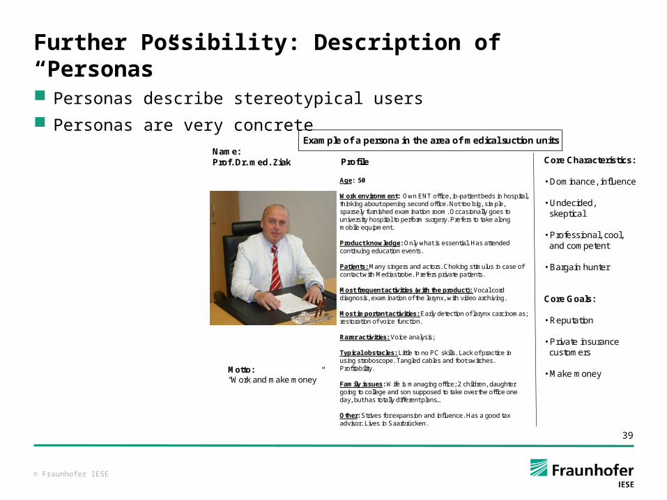
Personas describe stereotypical users Personas are very concrete
Motto: “Work and make money”
Name:Prof. Dr. med. Ziak Core Characteristics:
• Dominance, influence
• Undecided, skeptical
• Professional, cool, and competent
• Bargain hunter
Core Goals:
• Reputation
• Private insurance customers
• Make money
Profile
Age: 50
Work environment: Own ENT office, in-patient beds in hospital, thinking about opening second office. Not too big, simple, sparsely furnished examination room. Occasionally goes to university hospital to perform surgery. Prefers to take along mobile equipment.
Product knowledge: Only what is essential. Has attended continuing education events.
Patients: Many singers and actors. Choking stimulus in case of contact with Mediastrobe. Prefers private patients.
Most frequent activities (with the product): Vocal cord diagnosis, examination of the larynx, with video archiving.
Most important activities: Early detection of larynx carcinomas; restoration of voice function.
Rarer activities: Voice analysis;
Typical obstacles: Little to no PC skills. Lack of practice in using stroboscope. Tangled cables and foot switches. Profitability.
Family issues: Wife is managing office; 2 children, daughter going to college and son supposed to take over the office one day, but has totally different plans…
Other: Strives for expansion and influence. Has a good tax advisor. Lives in Saarbrücken.
Example of a persona in the area of medical suction units
© Fraunhofer IESE
40
Description of Tasks
Task evaluation Objectives Possibilities of engagement Causes
Task performance Initial situation (precondition, priority, occurrence, rate of
iterations) Info-In Info-Out Resources (means for work, actors, partners)
© Fraunhofer IESE
41
Description of Task „Book Return“
Objective: book is back in library Possibilities of engagement: check book quality Causes: Loan period expired or voluntary return Initial situation: book dispensed; high priority; frequent Info-In: book Info-Out: confirmation of return Resources: processor, book file, user file
© Fraunhofer IESE
42
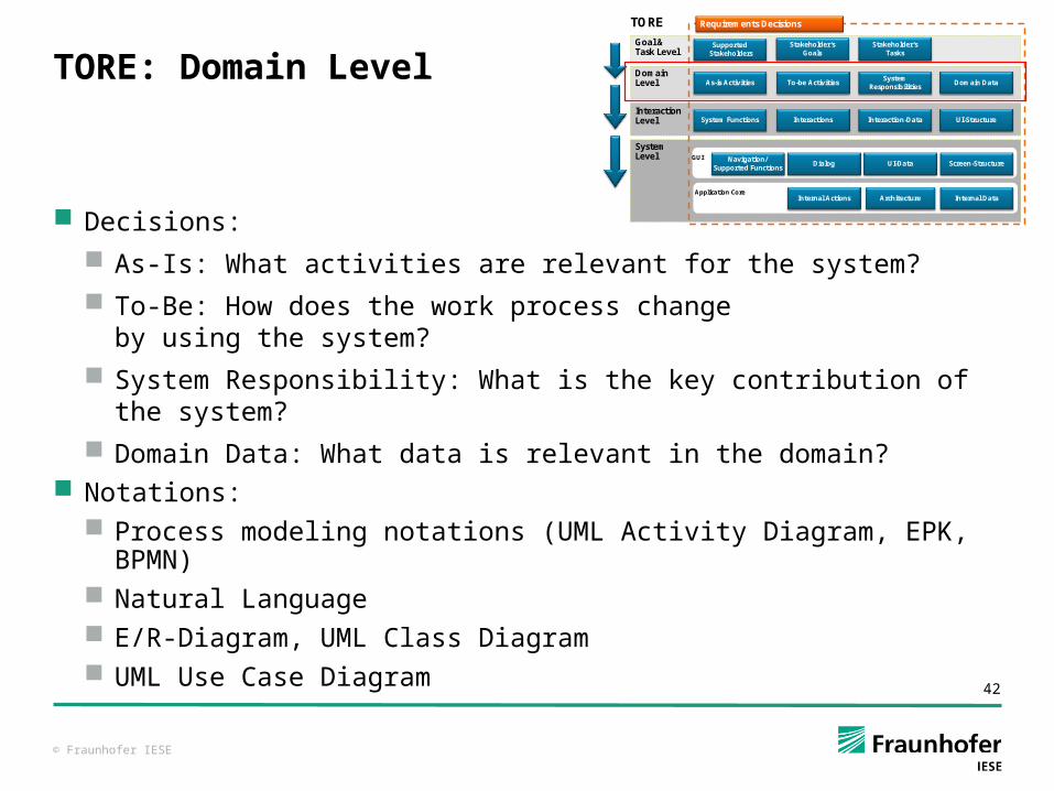
TORE: Domain Level
Decisions: As-Is: What activities are relevant for the system? To-Be: How does the work process change
by using the system? System Responsibility: What is the key contribution of the system? Domain Data: What data is relevant in the domain?
Notations: Process modeling notations (UML Activity Diagram, EPK, BPMN) Natural Language E/R-Diagram, UML Class Diagram UML Use Case Diagram
TORE
SupportedStakeholdersSupported
Stakeholders
Goal & Task Level
Domain Level
InteractionLevel
As-is ActivitiesAs-is Activities To-be ActivitiesTo-be ActivitiesSystem
ResponsibilitiesSystem
ResponsibilitiesDomain DataDomain Data
System FunctionsSystem Functions InteractionsInteractions Interaction-DataInteraction-Data UI-StructureUI-Structure
System Level
Requirements DecisionsRequirements Decisions
Internal ActionsInternal Actions Internal DataInternal DataArchitectureArchitectureApplication Core
Screen-StructureScreen-StructureNavigation/
Supported FunctionsNavigation/
Supported FunctionsDialogDialog UI-DataUI-Data
GUI
Stakeholder‘sGoals
Stakeholder‘sGoals
Stakeholder‘sTasks
Stakeholder‘sTasks
© Fraunhofer IESE
43
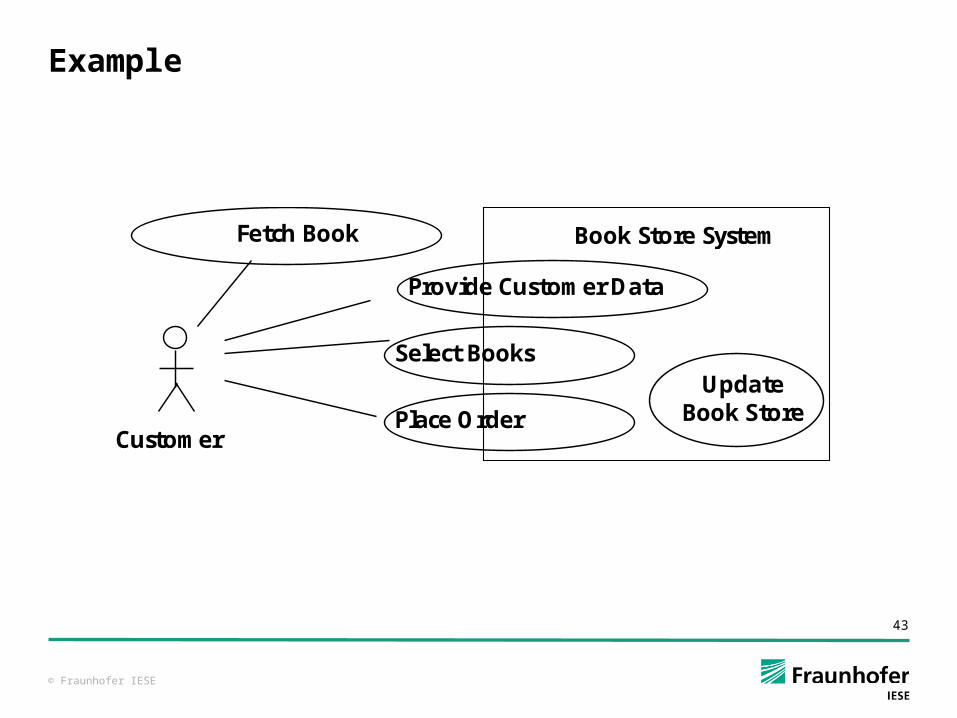
Example
Select Books
Customer Place Order
Book Store System
Provide Customer Data
Fetch Book
Update Book Store
© Fraunhofer IESE
44
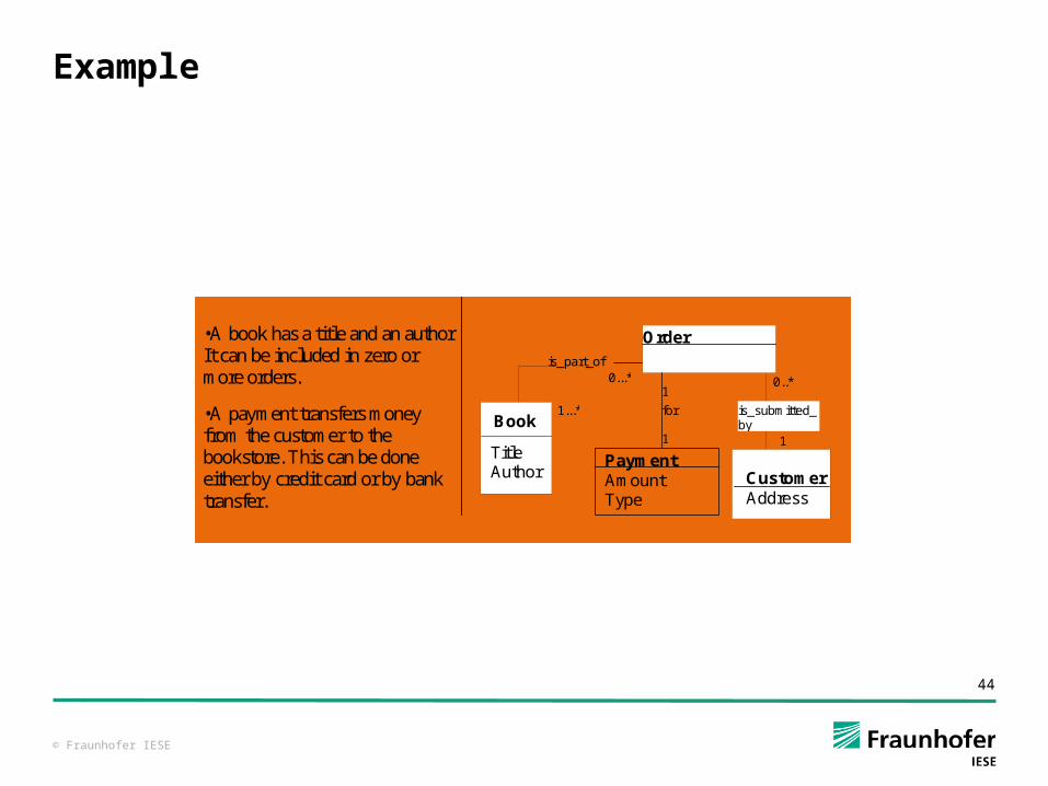
Example
Order
Customer Address
is_part_of 0..* 0...*
1...* Book Title Author
1
•A book has a title and an author. It can be included in zero or more orders.
•A payment transfers money from the customer to the bookstore. This can be done either by credit card or by bank transfer.
is_submitted_by
Payment Amount Type
1
1 for
© Fraunhofer IESE
45
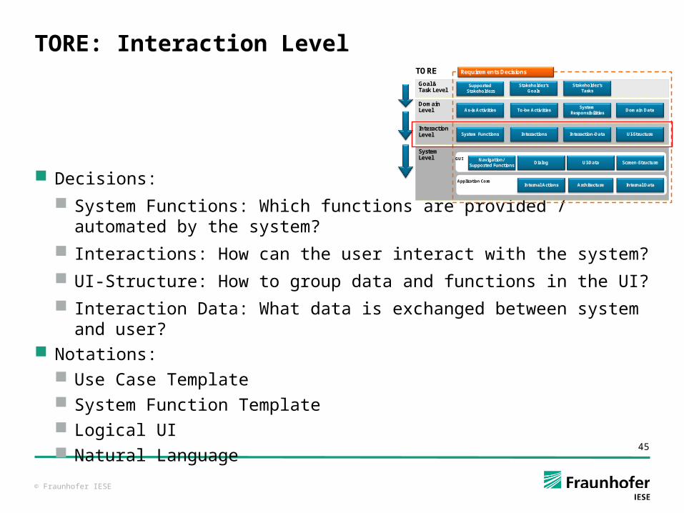
TORE: Interaction Level
Decisions: System Functions: Which functions are provided / automated by
the system? Interactions: How can the user interact with the system? UI-Structure: How to group data and functions in the UI? Interaction Data: What data is exchanged between system and
user? Notations:
Use Case Template System Function Template Logical UI Natural Language
TORE
SupportedStakeholdersSupported
Stakeholders
Goal & Task Level
Domain Level
InteractionLevel
As-is ActivitiesAs-is Activities To-be ActivitiesTo-be ActivitiesSystem
ResponsibilitiesSystem
ResponsibilitiesDomain DataDomain Data
System FunctionsSystem Functions InteractionsInteractions Interaction-DataInteraction-Data UI-StructureUI-Structure
System Level
Requirements DecisionsRequirements Decisions
Internal ActionsInternal Actions Internal DataInternal DataArchitectureArchitectureApplication Core
Screen-StructureScreen-StructureNavigation/
Supported FunctionsNavigation/
Supported FunctionsDialogDialog UI-DataUI-Data
GUI
Stakeholder‘sGoals
Stakeholder‘sGoals
Stakeholder‘sTasks
Stakeholder‘sTasks
© Fraunhofer IESE
46
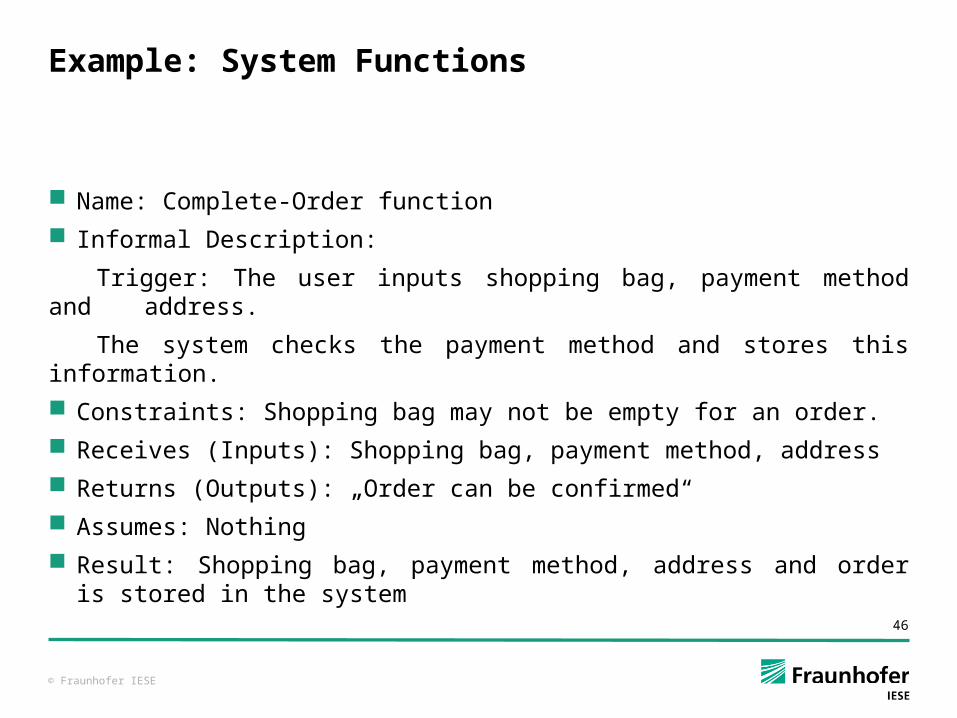
Example: System Functions
Name: Complete-Order function Informal Description:
Trigger: The user inputs shopping bag, payment method and address.
The system checks the payment method and stores this information. Constraints: Shopping bag may not be empty for an order. Receives (Inputs): Shopping bag, payment method, address Returns (Outputs): „Order can be confirmed“ Assumes: Nothing Result: Shopping bag, payment method, address and order is stored
in the system
© Fraunhofer IESE
47
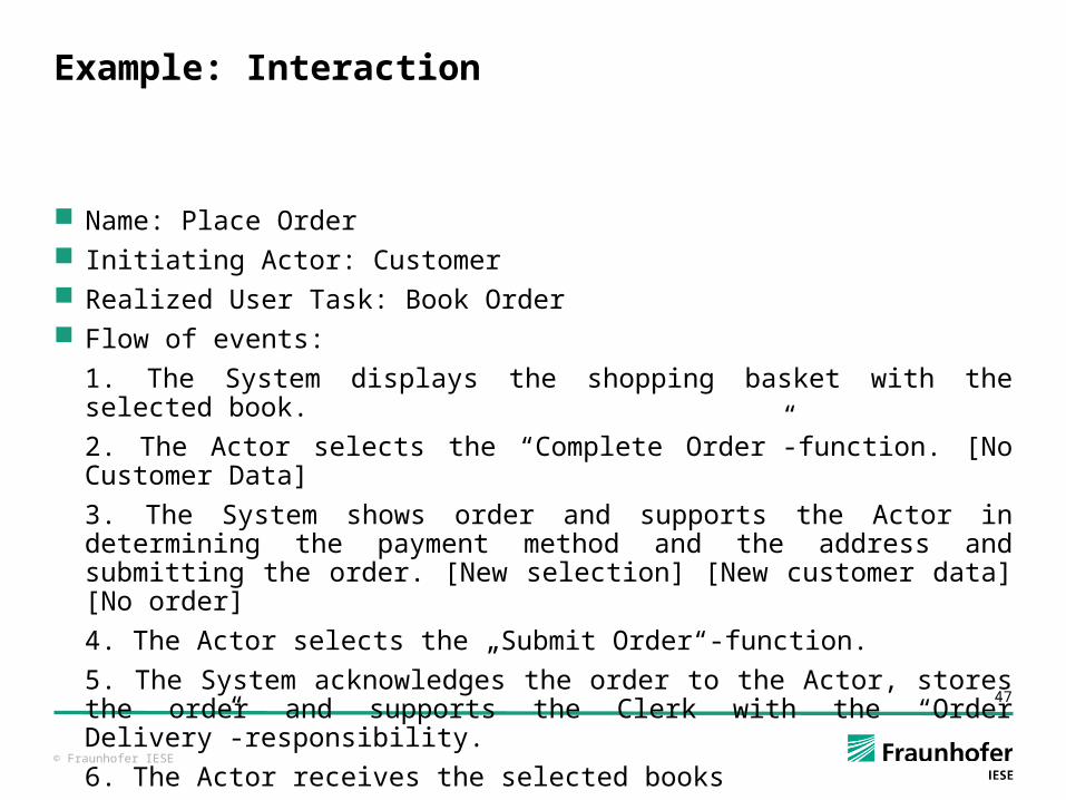
Example: Interaction
Name: Place Order Initiating Actor: Customer Realized User Task: Book Order Flow of events:
1. The System displays the shopping basket with the selected book.
2. The Actor selects the “Complete Order”-function. [No Customer Data]
3. The System shows order and supports the Actor in determining the payment method and the address and submitting the order. [New selection] [New customer data] [No order]
4. The Actor selects the „Submit Order“-function.
5. The System acknowledges the order to the Actor, stores the order and supports the Clerk with the “Order Delivery”-responsibility.
6. The Actor receives the selected books
...
© Fraunhofer IESE
48
Use Cases
Dominant approach of requirements analysis, especially for IT systems
Focusing on usage of systems
UML overview diagram
Textual approach (actually use case description)
© Fraunhofer IESE
49
Usage of Use Cases (1)
As description of functional requirements Comprehensible for users From perspective of the users Good connection to interface design Also as a unit for project planning
As medium for requirement analysis Modeling approach Detail, completeness, management (changeability) are less
important As medium for requirement specification
Presetting for draft Detail, completeness, management (changeability) very important
© Fraunhofer IESE
50
Usage of Use Cases (2)
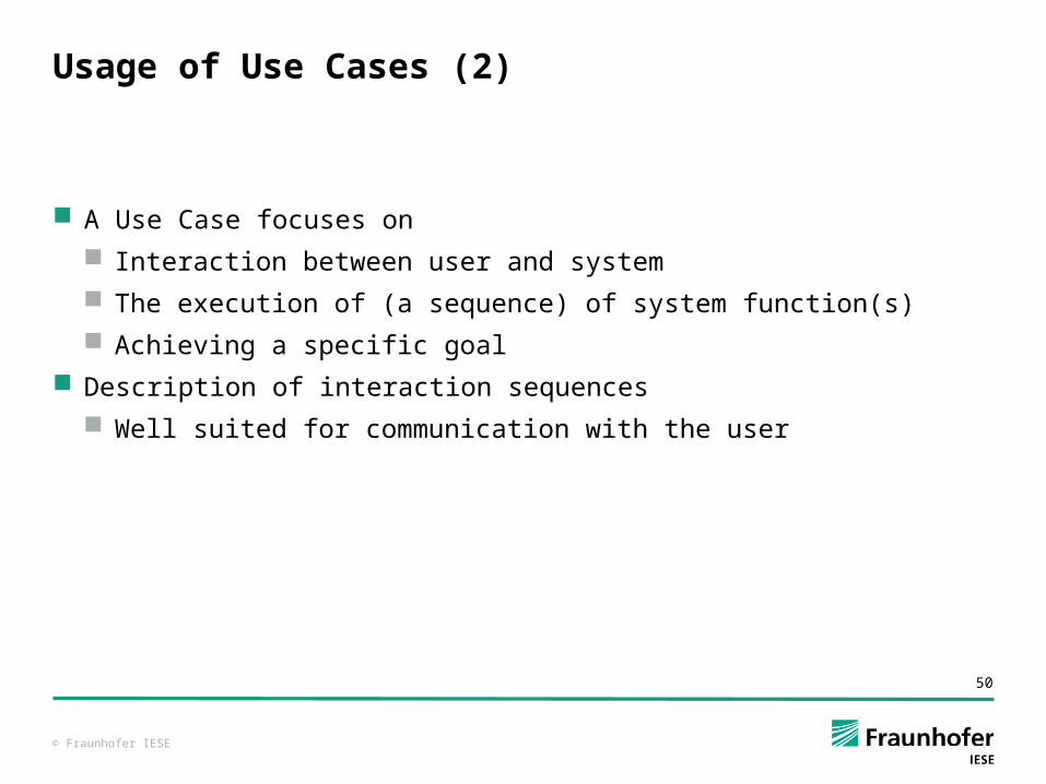
A Use Case focuses on Interaction between user and system The execution of (a sequence) of system function(s) Achieving a specific goal
Description of interaction sequences Well suited for communication with the user
© Fraunhofer IESE
51
Description of a Use Case (1)
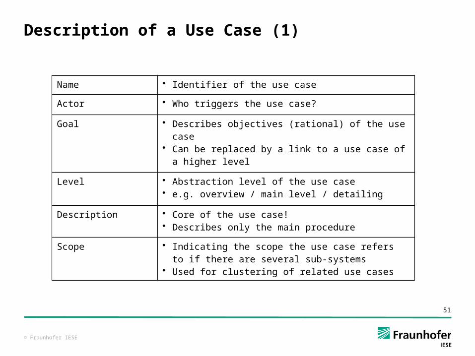
Name • Identifier of the use case
Actor • Who triggers the use case?
Goal • Describes objectives (rational) of the use case• Can be replaced by a link to a use case of a higher
level
Level • Abstraction level of the use case• e.g. overview / main level / detailing
Description • Core of the use case!• Describes only the main procedure
Scope • Indicating the scope the use case refers to if there are several sub-systems
• Used for clustering of related use cases
© Fraunhofer IESE
52
Description of a Use Case (2)
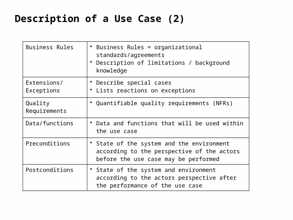
Business Rules • Business Rules = organizational standards/agreements
• Description of limitations / background knowledge
Extensions/ Exceptions
• Describe special cases• Lists reactions on exceptions
Quality Requirements
• Quantifiable quality requirements (NFRs)
Data/functions • Data and functions that will be used within the use case
Preconditions • State of the system and the environment according to the perspective of the actors before the use case may be performed
Postconditions • State of the system and environment according to the actors perspective after the performance of the use case
© Fraunhofer IESE
53
Use Case „Register User“ (1)
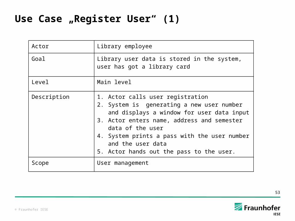
Actor Library employee
Goal Library user data is stored in the system, user has got a library card
Level Main level
Description 1. Actor calls user registration2. System is generating a new user number and
displays a window for user data input3. Actor enters name, address and semester data
of the user4. System prints a pass with the user number and
the user data5. Actor hands out the pass to the user.
Scope User management

© Fraunhofer IESE
54
Use Case „Register User“(2)
Business Rules User has to belong to the faculty
Extensions/ Exceptions
3a. In case there is already a user with the same name, the system asks, if there is really a new user at hand; if so, proceed with step 4.
Quality Requirements
Step 4: Execution time < 15 Seconds
Data/functions Data: user dataFunction: user registration, pass printing
Preconditions Librarian is logged in.
Post conditions A complete data record with a unique number exists for every user.
© Fraunhofer IESE
55
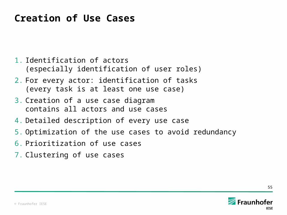
Creation of Use Cases
1. Identification of actors(especially identification of user roles)
2. For every actor: identification of tasks(every task is at least one use case)
3. Creation of a use case diagramcontains all actors and use cases
4. Detailed description of every use case
5. Optimization of the use cases to avoid redundancy
6. Prioritization of use cases
7. Clustering of use cases
© Fraunhofer IESE
58
Suitable Models for Different Aspects Summary
TORE is IESE’s framework for the typical reference objects to be discussed / decided within a RE process
Each reference object / decision point can be described / clarified with different notations
TORE has strong focus on users, their tasks and the desired human-system-interactions
Use Cases are a very popular approach for modeling such interactions
© Fraunhofer IESE
59
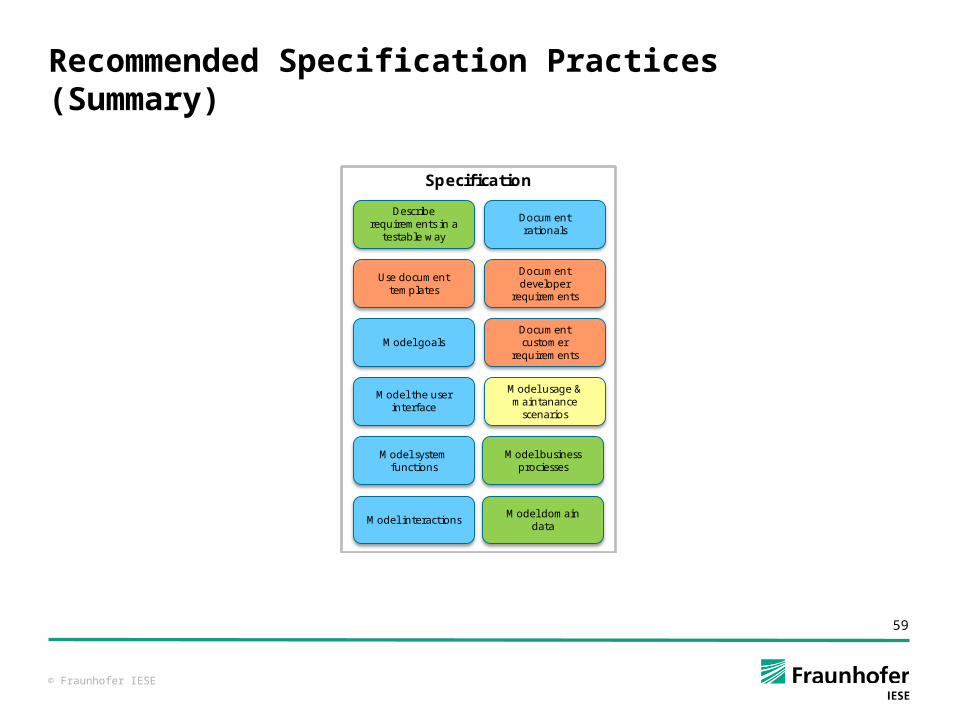
Recommended Specification Practices (Summary)
Specification
Model goals
Model interactionsModel domain
data
Model system functions
Model business prociesses
Model the user interface
Model usage & maintanance
scenarios
Document customer
requirements
Document developer
requirements
Use document templates
Describe requirements in a
testable way
Document rationals
© Fraunhofer IESE
60
Questions
?Specification