Embed Size (px)
Citation preview
D2
TAN/WHTTAN/BLK
51820
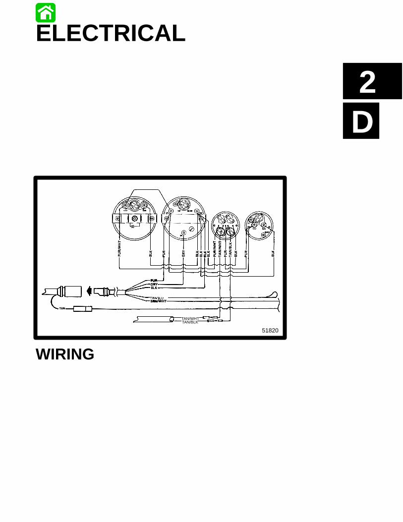
ELECTRICAL
WIRING
2D-0 - ELECTRICAL 90-822900R3 DECEMBER 1997
Table of ContentsPage
Power Trim Wiring Diagram 1994 Models 2D-1. . . . . . . Power Trim Wiring Diagram1995/1996/1997/1998 Models 2D-2. . . . . . . . . . . . . . . . . Commander 3000 Classic Panel Remote Control 2D-4. Commander 3000 Panel Remote Control 2D-5. . . . . . . . Commander Side Mount Remote Control(Power Trim/Tilt Electric Start with Warning Horn)Wiring Diagram 2D-8. . . . . . . . . . . . . . . . . . . . . . . . . . . . . . Commander 2000 Side Mount Remote Control(Power Trim/Tilt Electric Start with Warning Horn)Wiring Diagram 2D-9. . . . . . . . . . . . . . . . . . . . . . . . . . . . . . Instrument/Lanyard Stop Switch Wiring Diagram 2D-10Oil Level Gauge Wiring Diagram 2D-11. . . . . . . . . . . . . . Instrument/Lanyard Stop Switch Wiring Diagram(Dual Outboard) 2D-12. . . . . . . . . . . . . . . . . . . . . . . . . . . . . QSI Gauge Wiring Diagrams 2D-14. . . . . . . . . . . . . . . . . .
Tachometer Wiring Diagram 2D-14. . . . . . . . . . . . . . . Water Temperature Gauge 2D-14. . . . . . . . . . . . . . . . Oil Level Gauge Wiring 2D-15. . . . . . . . . . . . . . . . . . . . Engine Synchronizer Wiring Diagram 2D-16. . . . . . .
Maintenance 2D-16. . . . . . . . . . . . . . . . . . . . . . . . . . . . . . . . 2 Function Gauge (Carburetor Models) 2D-17. . . . . . . . .
Operation of Warning Panel 2D-17. . . . . . . . . . . . . . . Multi-Function Gauge 2D-19. . . . . . . . . . . . . . . . . . . . . . . . 225 EFI/250 EFI Warning Panel(3 Function Gauge) 2D-20. . . . . . . . . . . . . . . . . . . . . . . . . .
Operation of Warning Panel 2D-20. . . . . . . . . . . . . . . Maintenance 2D-21. . . . . . . . . . . . . . . . . . . . . . . . . . . . .
Panel Mount Remote Control Wiring Installation 2D-22. Side Mount Remote Control Wiring Installation 2D-23.
1994 225 Wiring Diagram 2D-24. . . . . . . . . . . . . . . . .
ELECTRICAL - 2D-190-822900R3 DECEMBER 1997
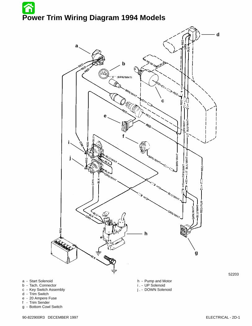
Power Trim Wiring Diagram 1994 Models
52203
a
b
c
d
e
f
g
h
i
j
a - Start Solenoidb - Tach. Connectorc - Key Switch Assemblyd - Trim Switche - 20 Ampere Fusef - Trim Senderg - Bottom Cowl Switch
h - Pump and Motori - UP Solenoid. j - DOWN Solenoid.
2D-2 - ELECTRICAL 90-822900R3 DECEMBER 1997
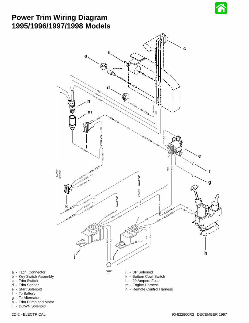
Power Trim Wiring Diagram1995/1996/1997/1998 Models
ab
c
d
e
f
g
hij
k
l
m
n
a - Tach. Connectorb - Key Switch Assemblyc - Trim Switchd - Trim Sendere - Start Solenoidf - To Batteryg - To Alternatorh - Trim Pump and Motori - DOWN Solenoid.
j - UP Solenoid. k - Bottom Cowl Switchl - 20 Ampere Fuse. m - Engine Harnessn - Remote Control Harness
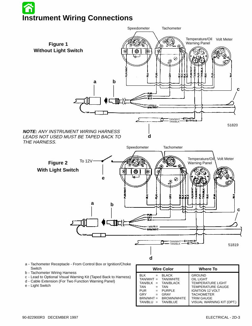
Speedometer Tachometer
Temperature/Oil Warning Panel
Volt Meter
Instrument Wiring Connections
Figure 1Without Light Switch
Figure 2With Light Switch
NOTE: ANY INSTRUMENT WIRING HARNESSLEADS NOT USED MUST BE TAPED BACK TOTHE HARNESS.
TAN/WHTTAN/BLK
TAN/WHTTAN/BLK
a - Tachometer Receptacle - From Control Box or Ignition/ChokeSwitch
b - Tachometer Wiring Harnessc - Lead to Optional Visual Warning Kit (Taped Back to Harness)d - Cable Extension (For Two Function Warning Panel)e - Light Switch
Speedometer Tachometer
Temperature/Oil Warning Panel
Volt Meter
51819
51820
To 12V
BLK = BLACK GROUNDTAN/WHT = TAN/WHITE OIL LIGHTTAN/BLK = TAN/BLACK TEMPERATURE LIGHTTAN = TAN TEMPERATURE GAUGEPUR = PURPLE IGNITION 12 VOLTGRY = GRAY TACHOMETERBRN/WHT = BROWN/WHITE TRIM GAUGETAN/BLU = TAN/BLUE VISUAL WARNING KIT (OPT.)
Wire Color Where To
a b
d
c
e
a b
d
c
ELECTRICAL - 2D-390-822900R3 DECEMBER 1997
2D-4 - ELECTRICAL 90-822900R3 DECEMBER 1997
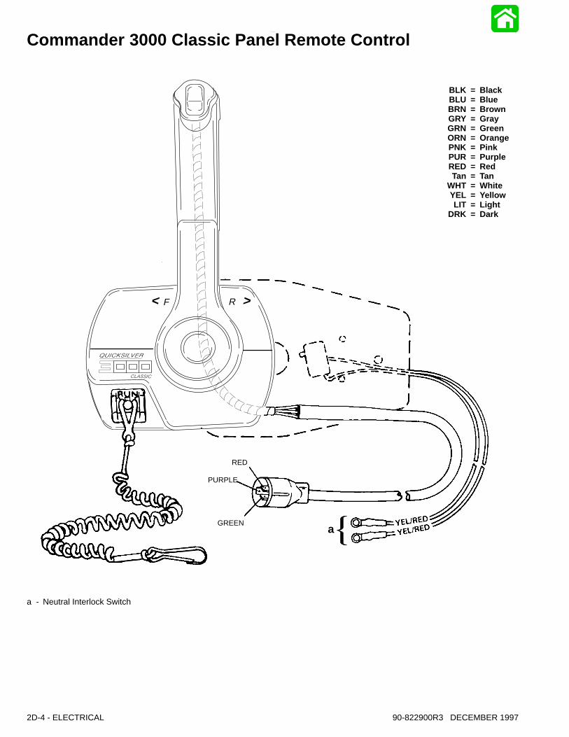
Commander 3000 Classic Panel Remote Control
F R< >
RED
PURPLE
GREEN
BLK = BlackBLU = BlueBRN = BrownGRY = GrayGRN = GreenORN = OrangePNK = PinkPUR = PurpleRED = RedTan = Tan
WHT = WhiteYEL = YellowLIT = Light
DRK = Dark
a
a - Neutral Interlock Switch
ELECTRICAL - 2D-590-822900R3 DECEMBER 1997
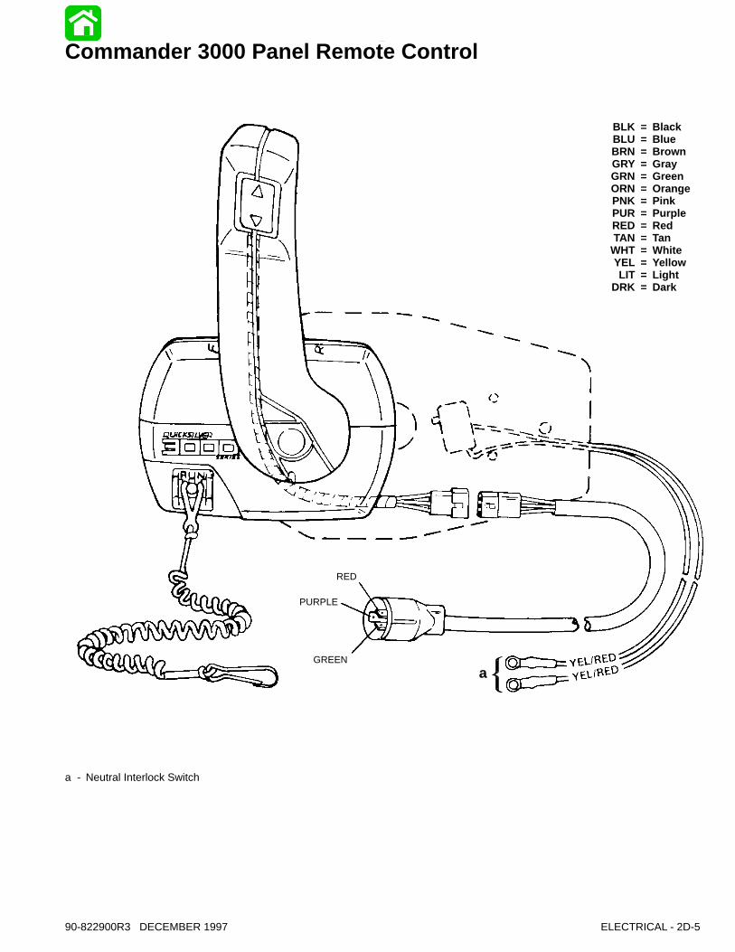
Commander 3000 Panel Remote Control
RED
PURPLE
GREEN
BLK = BlackBLU = BlueBRN = BrownGRY = GrayGRN = GreenORN = OrangePNK = PinkPUR = PurpleRED = RedTAN = Tan
WHT = WhiteYEL = YellowLIT = Light
DRK = Dark
a
a - Neutral Interlock Switch
12 3
4
5
6
7
8
91011
12
13
1415
16
17
18
19
20
21
2223
24
25
2627
28 17
23
95 2-4-C With Teflon (92-825407A12)
95
95
95
95
95
7
7
95
95
95
7 Loctite 271 (92-809820)
2D-6 - ELECTRICAL 90-822900R3 DECEMBER 1997
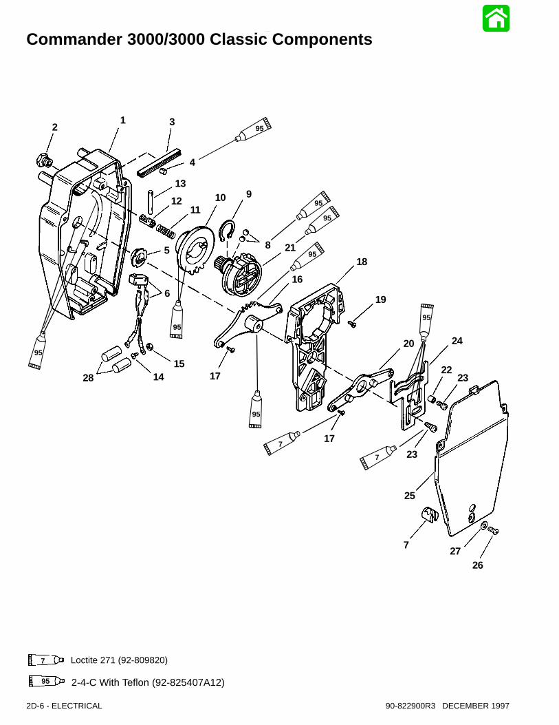
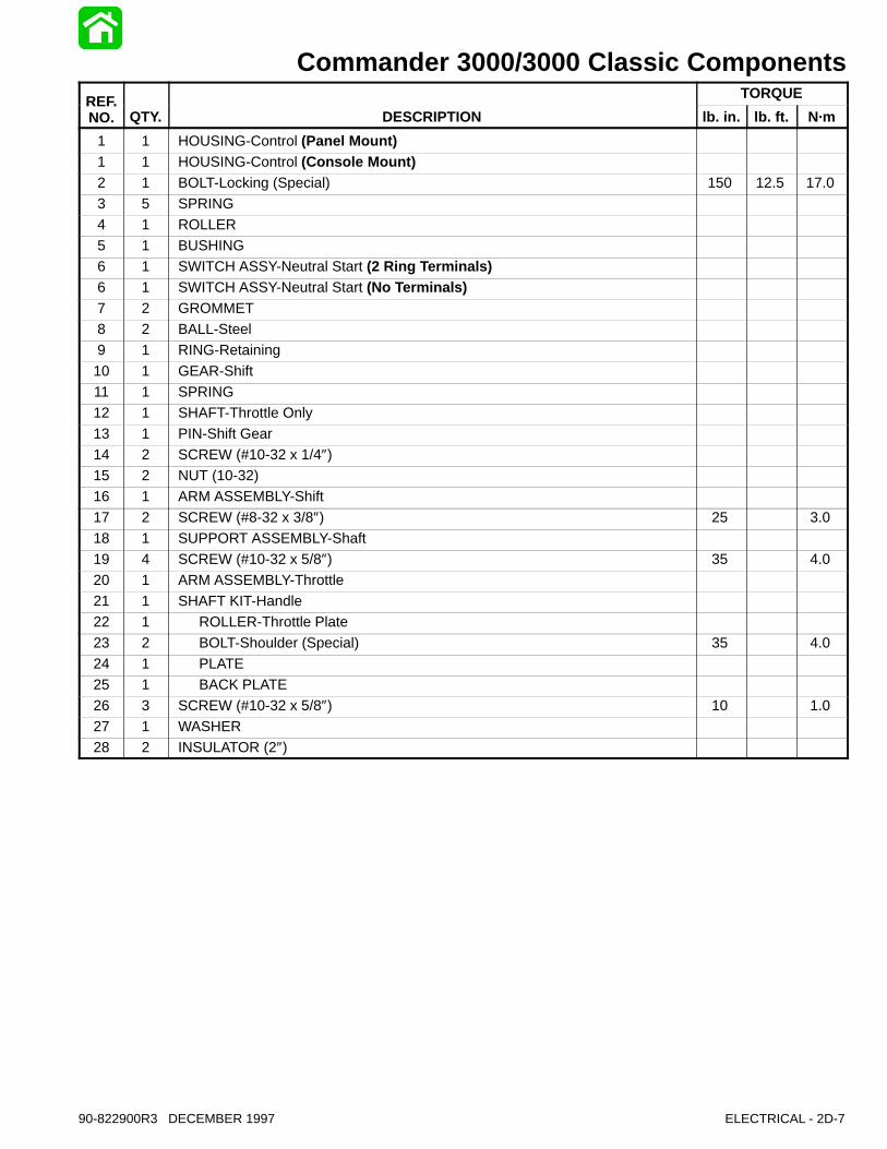
Commander 3000/3000 Classic Components
ELECTRICAL - 2D-790-822900R3 DECEMBER 1997
Commander 3000/3000 Classic ComponentsREF. TORQUEREF.NO. QTY. DESCRIPTION lb. in. lb. ft. N·m
1 1 HOUSING-Control (Panel Mount)1 1 HOUSING-Control (Console Mount)2 1 BOLT-Locking (Special) 150 12.5 17.03 5 SPRING
4 1 ROLLER5 1 BUSHING6 1 SWITCH ASSY-Neutral Start (2 Ring Terminals)6 1 SWITCH ASSY-Neutral Start (No Terminals)7 2 GROMMET8 2 BALL-Steel9 1 RING-Retaining
10 1 GEAR-Shift11 1 SPRING12 1 SHAFT-Throttle Only13 1 PIN-Shift Gear14 2 SCREW (#10-32 x 1/4″)15 2 NUT (10-32)16 1 ARM ASSEMBLY-Shift
17 2 SCREW (#8-32 x 3/8″) 25 3.018 1 SUPPORT ASSEMBLY-Shaft19 4 SCREW (#10-32 x 5/8″) 35 4.020 1 ARM ASSEMBLY-Throttle21 1 SHAFT KIT-Handle22 1 ROLLER-Throttle Plate
23 2 BOLT-Shoulder (Special) 35 4.024 1 PLATE25 1 BACK PLATE26 3 SCREW (#10-32 x 5/8″) 10 1.027 1 WASHER28 2 INSULATOR (2″)
2D-8 - ELECTRICAL 90-822900R3 DECEMBER 1997
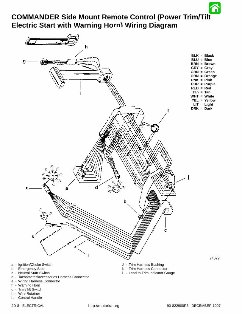
COMMANDER Side Mount Remote Control (Power Trim/TiltElectric Start with Warning Horn) Wiring Diagram
BLK = BlackBLU = BlueBRN = BrownGRY = GrayGRN = GreenORN = OrangePNK = PinkPUR = PurpleRED = RedTan = Tan
WHT = WhiteYEL = YellowLIT = Light
DRK = Dark
24072
a
b
c
de
f
g
h
i
j
k
l
a - Ignition/Choke Switchb - Emergency Stopc - Neutral Start Switchd - Tachometer/Accessories Harness Connectore - Wiring Harness Connectorf - Warning Horng - Trim/Tilt Switchh - Wire Retaineri - Control Handle.
J - Trim Harness Bushingk - Trim Harness Connectorl - Lead to Trim Indicator Gauge.
http://motorka.org
ELECTRICAL - 2D-990-822900R3 DECEMBER 1997
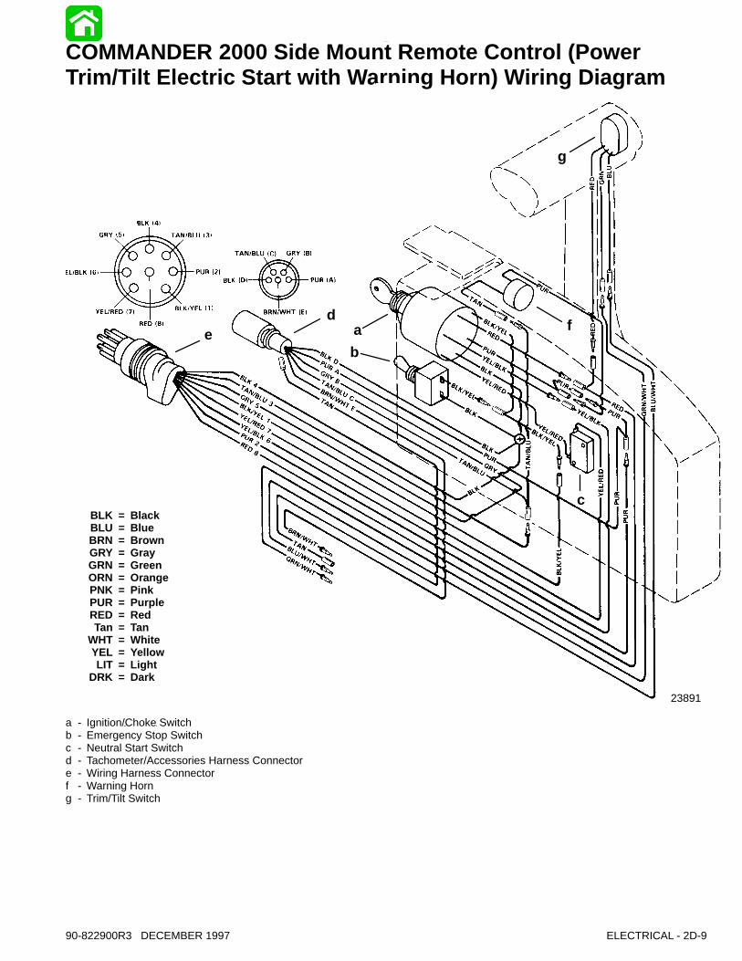
COMMANDER 2000 Side Mount Remote Control (PowerTrim/Tilt Electric Start with Warning Horn) Wiring Diagram
23891
ad
b
f
g
c
e
BLK = BlackBLU = BlueBRN = BrownGRY = GrayGRN = GreenORN = OrangePNK = PinkPUR = PurpleRED = RedTan = Tan
WHT = WhiteYEL = YellowLIT = Light
DRK = Dark
a - Ignition/Choke Switchb - Emergency Stop Switchc - Neutral Start Switchd - Tachometer/Accessories Harness Connectore - Wiring Harness Connectorf - Warning Horng - Trim/Tilt Switch
2D-10 - ELECTRICAL 90-822900R3 DECEMBER 1997
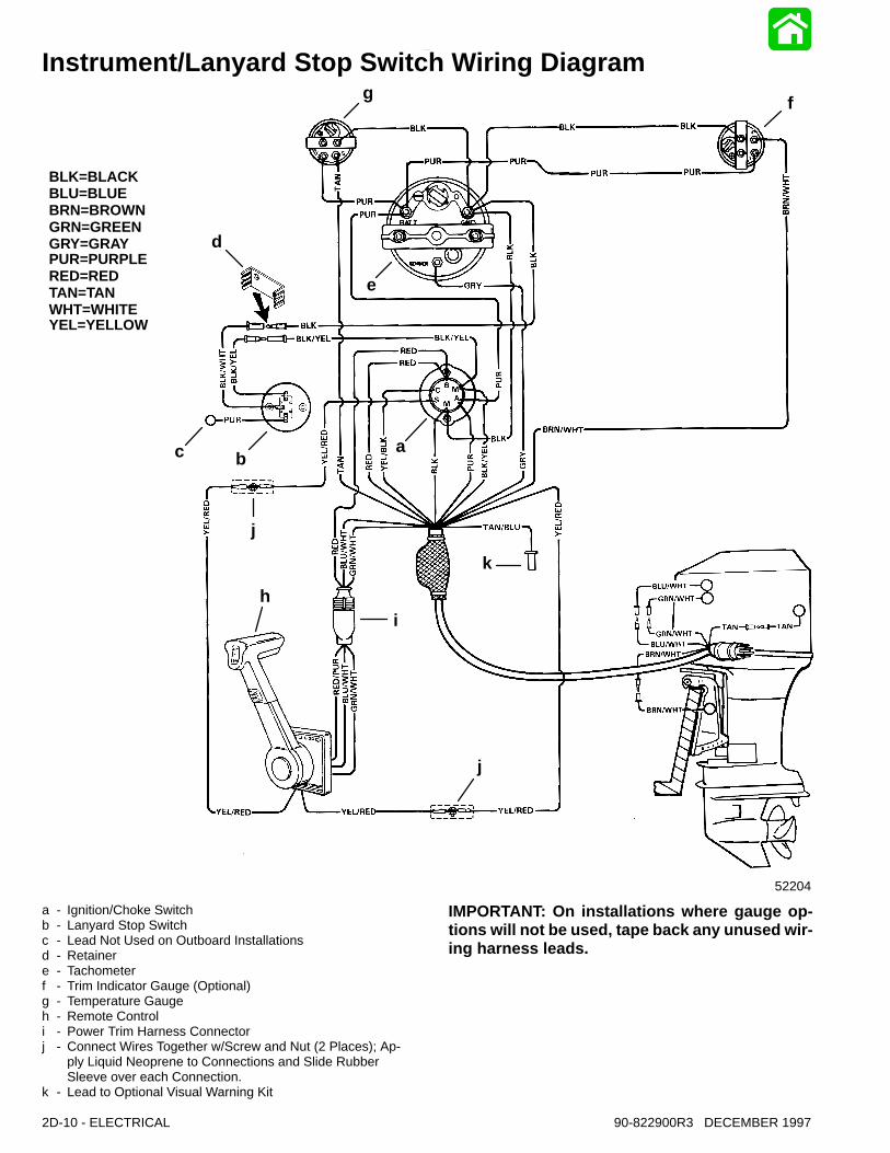
Instrument/Lanyard Stop Switch Wiring Diagram
BLK=BLACKBLU=BLUEBRN=BROWNGRN=GREENGRY=GRAYPUR=PURPLERED=REDTAN=TANWHT=WHITEYEL=YELLOW
52204
g
d
e
f
abc
j
i
k
j
h
a - Ignition/Choke Switchb - Lanyard Stop Switchc - Lead Not Used on Outboard Installationsd - Retainere - Tachometerf - Trim Indicator Gauge (Optional)g - Temperature Gaugeh - Remote Controli - Power Trim Harness Connectorj - Connect Wires Together w/Screw and Nut (2 Places); Ap-
ply Liquid Neoprene to Connections and Slide Rubber Sleeve over each Connection.
k - Lead to Optional Visual Warning Kit
IMPORTANT: On installations where gauge op-tions will not be used, tape back any unused wir-ing harness leads.
ELECTRICAL - 2D-1190-822900R3 DECEMBER 1997
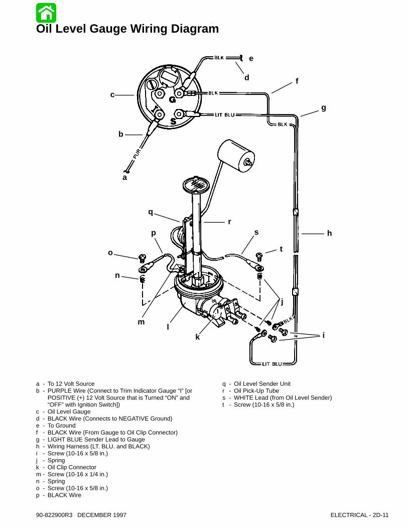
Oil Level Gauge Wiring Diagram
a
b
c
i
o
m
n
j
kl
h
g
f
p
qr
s
t
e
d
a - To 12 Volt Sourceb - PURPLE Wire (Connect to Trim Indicator Gauge “I” [or
POSITIVE (+) 12 Volt Source that is Turned “ON” and “OFF” with Ignition Switch])
c - Oil Level Gauged - BLACK Wire (Connects to NEGATIVE Ground)e - To Groundf - BLACK Wire (From Gauge to Oil Clip Connector)g - LIGHT BLUE Sender Lead to Gaugeh - Wiring Harness (LT. BLU. and BLACK)i - Screw (10-16 x 5/8 in.)j - Springk - Oil Clip Connectorm - Screw (10-16 x 1/4 in.)n - Springo - Screw (10-16 x 5/8 in.)p - BLACK Wire
q - Oil Level Sender Unitr - Oil Pick-Up Tubes - WHITE Lead (from Oil Level Sender)t - Screw (10-16 x 5/8 in.)
2D-12 - ELECTRICAL 90-822900R3 DECEMBER 1997
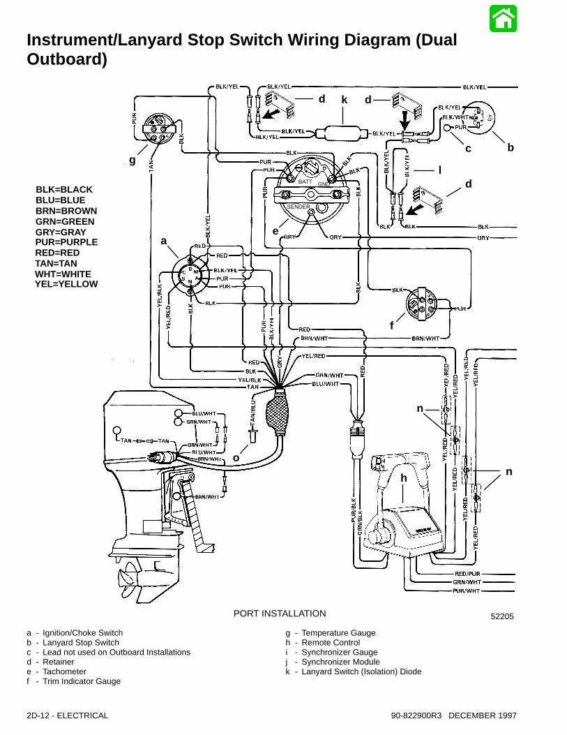
Instrument/Lanyard Stop Switch Wiring Diagram (DualOutboard)
BLK=BLACKBLU=BLUEBRN=BROWNGRN=GREENGRY=GRAYPUR=PURPLERED=REDTAN=TANWHT=WHITEYEL=YELLOW
52205
g
ae
d k d
bc
ld
f
nh
o
BATT GND
SENDER
PORT INSTALLATION
n
a - Ignition/Choke Switchb - Lanyard Stop Switchc - Lead not used on Outboard Installationsd - Retainere - Tachometerf - Trim Indicator Gauge
g - Temperature Gaugeh - Remote Controli - Synchronizer Gaugej - Synchronizer Modulek - Lanyard Switch (Isolation) Diode

ELECTRICAL - 2D-1390-822900R3 DECEMBER 1997
IMPORTANT: On installations where gauge op-tions will not be used, tape back and isolate un-used wiring harness leads
52206
i
g
ae
jf
m
o
STARBOARD INSTALLATION
BATT GND
SENDER
l - Y Harnessm - Power Trim Harness Connectorn - Connect Wires together with Screw and Nut (4 Places);
Apply Liquid Neoprene to Connections and slide Rubber Sleeve over each Connection.
o - Lead to Visual Warning Kit
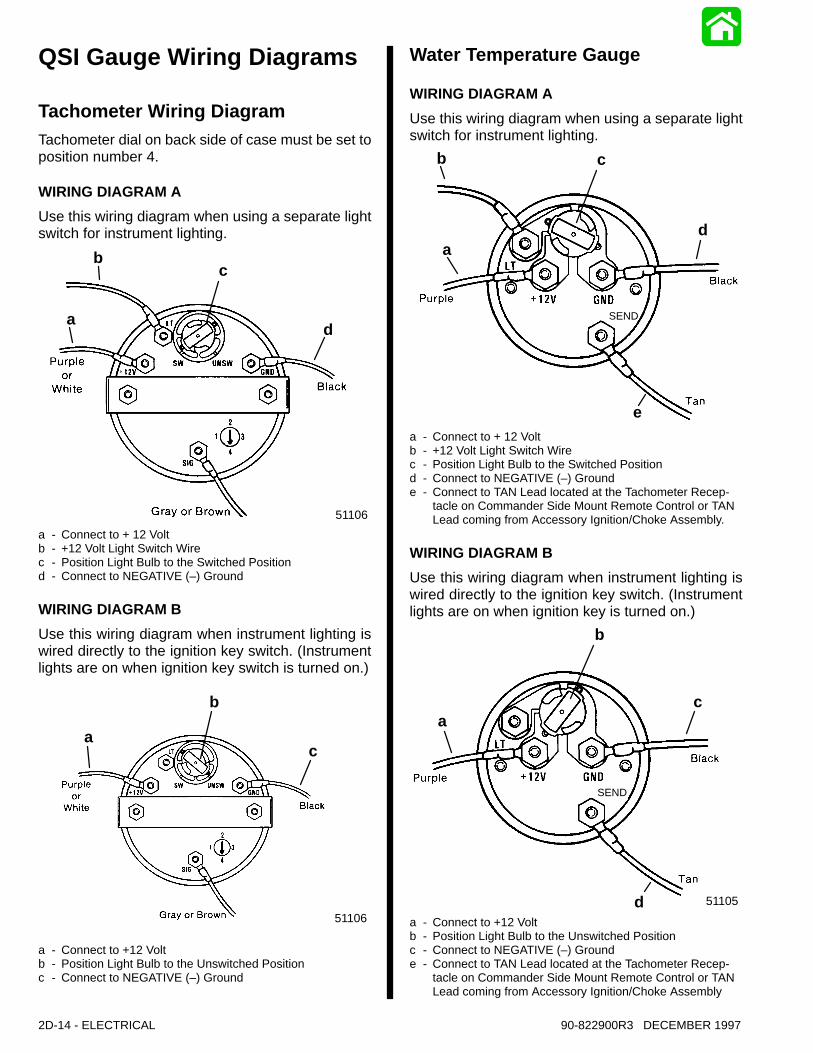
2D-14 - ELECTRICAL 90-822900R3 DECEMBER 1997
QSI Gauge Wiring Diagrams
Tachometer Wiring DiagramTachometer dial on back side of case must be set toposition number 4.
WIRING DIAGRAM A
Use this wiring diagram when using a separate lightswitch for instrument lighting.
51106
da
bc
a - Connect to + 12 Voltb - +12 Volt Light Switch Wirec - Position Light Bulb to the Switched Positiond - Connect to NEGATIVE (–) Ground
WIRING DIAGRAM B
Use this wiring diagram when instrument lighting iswired directly to the ignition key switch. (Instrumentlights are on when ignition key switch is turned on.)
51106
a
b
c
a - Connect to +12 Voltb - Position Light Bulb to the Unswitched Positionc - Connect to NEGATIVE (–) Ground
Water Temperature Gauge
WIRING DIAGRAM A
Use this wiring diagram when using a separate lightswitch for instrument lighting.
SEND
a
b c
d
ea - Connect to + 12 Voltb - +12 Volt Light Switch Wirec - Position Light Bulb to the Switched Positiond - Connect to NEGATIVE (–) Grounde - Connect to TAN Lead located at the Tachometer Recep-
tacle on Commander Side Mount Remote Control or TAN Lead coming from Accessory Ignition/Choke Assembly.
WIRING DIAGRAM B
Use this wiring diagram when instrument lighting iswired directly to the ignition key switch. (Instrumentlights are on when ignition key is turned on.)
51105
SEND
a
b
c
da - Connect to +12 Voltb - Position Light Bulb to the Unswitched Positionc - Connect to NEGATIVE (–) Grounde - Connect to TAN Lead located at the Tachometer Recep-
tacle on Commander Side Mount Remote Control or TAN Lead coming from Accessory Ignition/Choke Assembly
ELECTRICAL - 2D-1590-822900R3 DECEMBER 1997
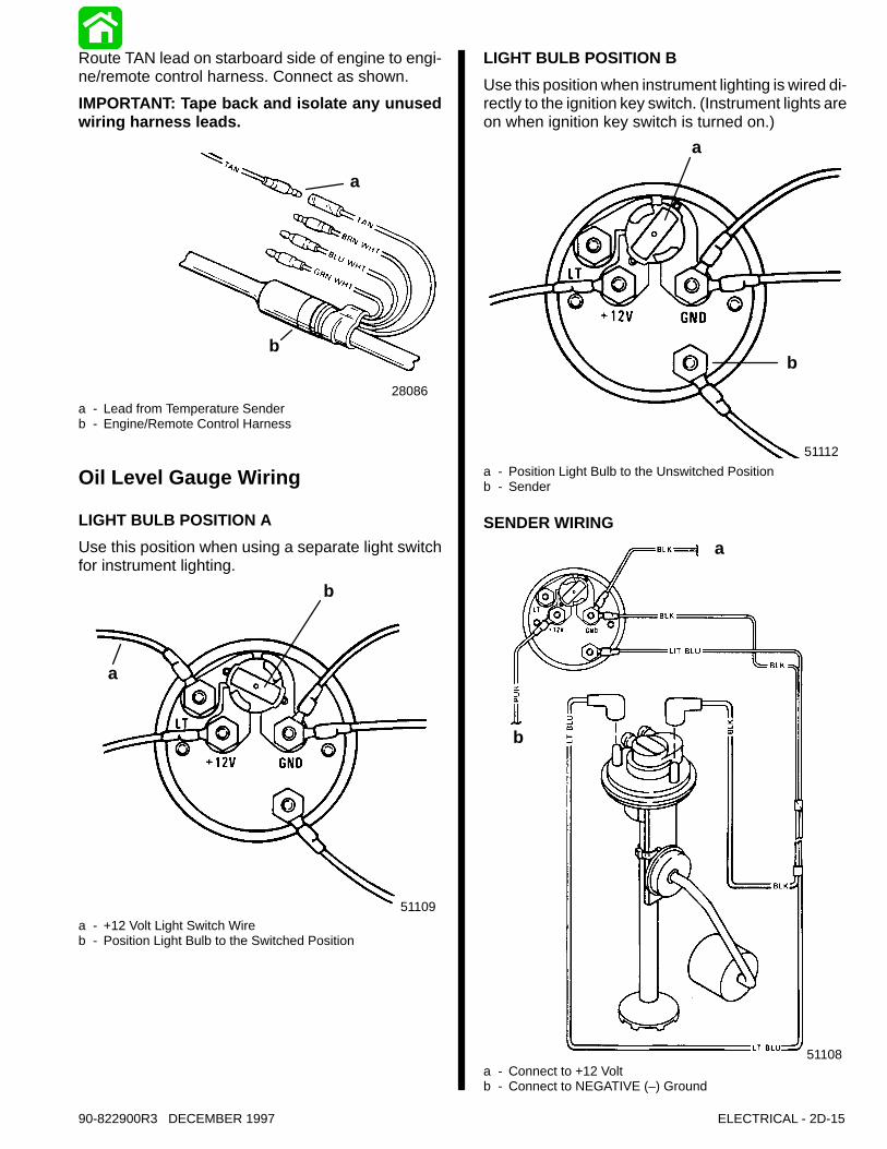
Route TAN lead on starboard side of engine to engi-ne/remote control harness. Connect as shown.
IMPORTANT: Tape back and isolate any unusedwiring harness leads.
28086
a
b
a - Lead from Temperature Senderb - Engine/Remote Control Harness
Oil Level Gauge Wiring
LIGHT BULB POSITION A
Use this position when using a separate light switchfor instrument lighting.
a
b
51109a - +12 Volt Light Switch Wireb - Position Light Bulb to the Switched Position
LIGHT BULB POSITION B
Use this position when instrument lighting is wired di-rectly to the ignition key switch. (Instrument lights areon when ignition key switch is turned on.)
a
51112
b
a - Position Light Bulb to the Unswitched Positionb - Sender
SENDER WIRING
51108
a
b
a - Connect to +12 Voltb - Connect to NEGATIVE (–) Ground
2D-16 - ELECTRICAL 90-822900R3 DECEMBER 1997
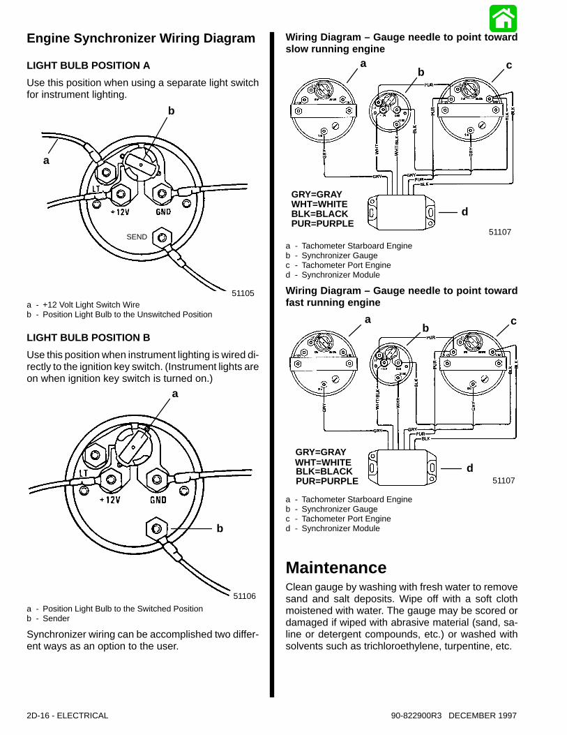
Engine Synchronizer Wiring Diagram
LIGHT BULB POSITION A
Use this position when using a separate light switchfor instrument lighting.
SEND
a
b
51105a - +12 Volt Light Switch Wireb - Position Light Bulb to the Unswitched Position
LIGHT BULB POSITION B
Use this position when instrument lighting is wired di-rectly to the ignition key switch. (Instrument lights areon when ignition key switch is turned on.)
a
b
51106
a - Position Light Bulb to the Switched Positionb - Sender
Synchronizer wiring can be accomplished two differ-ent ways as an option to the user.
Wiring Diagram – Gauge needle to point towardslow running engine
GRY=GRAYWHT=WHITEBLK=BLACKPUR=PURPLE
51107
ab
c
d
a - Tachometer Starboard Engineb - Synchronizer Gaugec - Tachometer Port Engined - Synchronizer Module
Wiring Diagram – Gauge needle to point towardfast running engine
GRY=GRAYWHT=WHITEBLK=BLACKPUR=PURPLE
ab
c
d51107
a - Tachometer Starboard Engineb - Synchronizer Gaugec - Tachometer Port Engined - Synchronizer Module
MaintenanceClean gauge by washing with fresh water to removesand and salt deposits. Wipe off with a soft clothmoistened with water. The gauge may be scored ordamaged if wiped with abrasive material (sand, sa-line or detergent compounds, etc.) or washed withsolvents such as trichloroethylene, turpentine, etc.

ELECTRICAL - 2D-1790-822900R3 DECEMBER 1997
2 Function Gauge(Carburetor Models)
Operation of Warning PanelWhen the ignition key is initially turned on, the warn-ing horn will sound (beep) for a moment as a test totell you the system is working. Failure of this testsound (beep) indicates a problem with the outboardor warning panel.
LOW OIL LEVEL
The low oil level warning is activated when the re-maining oil in the engine mounted oil reservoir tankdrops below 50 fl. oz. (1.5 liters).The Low Oil Indicator Light will come on and thewarning horn will begin a series of four beeps. If youcontinue to operate the outboard, the light will stay onand the horn will beep every two minutes.The enginehas to be shut off to reset the warning system.
a
a - Low Oil Level Indicator Light
ENGINE OVERHEAT
The engine overheat warning is activated when theengine temperature is too hot.The Engine Overheat Indicator Light will come onand the warning horn sounds continuously. Thewarning system will automatically limit the enginespeed to 3000 RPM.
a
a - Engine Overheat Indicator Light
ENGINE OVER-SPEED
The engine over-speed protection system is acti-vated when the engine speed exceeds the maximumallowable RPM.Anytime the engine over-speed system is activated,the warning horn begins beeping and the EngineOverheat and Low Oil Indicator Lights will turn on andalternately flash. In addition, the system will automat-ically reduce the engine speed to within the allowablelimit by retarding the ignition timing.
ab
a - Low Oil Level Indicator Lightb - Engine Overheat Indicator Light
ELECTRICAL SENSOR NOT FUNCTIONING
The warning system is activated if the electricalthrottle sensor or engine temperature sensor is notfunctioning, or is out of its operating range.The warning horn begins beeping and the EngineOverheat and Low Oil Indicator Lights will turn on andalternately flash.
ab
a - Low Oil Level Indicator Lightb - Engine Overheat Indicator Light
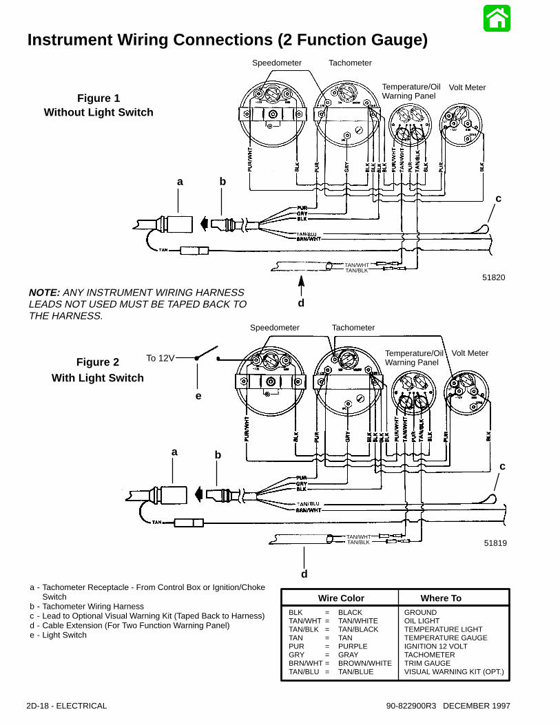
Speedometer Tachometer
Temperature/Oil Warning Panel
Volt Meter
Instrument Wiring Connections (2 Function Gauge)
Figure 1Without Light Switch
Figure 2With Light Switch
NOTE: ANY INSTRUMENT WIRING HARNESSLEADS NOT USED MUST BE TAPED BACK TOTHE HARNESS.
TAN/WHTTAN/BLK
TAN/WHTTAN/BLK
a - Tachometer Receptacle - From Control Box or Ignition/ChokeSwitch
b - Tachometer Wiring Harnessc - Lead to Optional Visual Warning Kit (Taped Back to Harness)d - Cable Extension (For Two Function Warning Panel)e - Light Switch
Speedometer Tachometer
Temperature/Oil Warning Panel
Volt Meter
51819
51820
To 12V
BLK = BLACK GROUNDTAN/WHT = TAN/WHITE OIL LIGHTTAN/BLK = TAN/BLACK TEMPERATURE LIGHTTAN = TAN TEMPERATURE GAUGEPUR = PURPLE IGNITION 12 VOLTGRY = GRAY TACHOMETERBRN/WHT = BROWN/WHITE TRIM GAUGETAN/BLU = TAN/BLUE VISUAL WARNING KIT (OPT.)
Wire Color Where To
a b
d
c
e
a b
d
c
2D-18 - ELECTRICAL 90-822900R3 DECEMBER 1997
ELECTRICAL - 2D-1990-822900R3 DECEMBER 1997
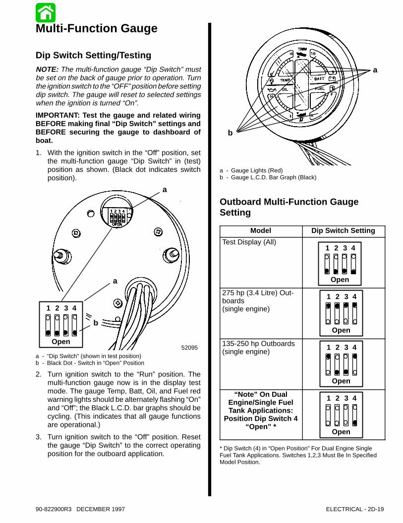
Multi-Function Gauge
Dip Switch Setting/TestingNOTE: The multi-function gauge “Dip Switch” mustbe set on the back of gauge prior to operation. Turnthe ignition switch to the “OFF” position before settingdip switch. The gauge will reset to selected settingswhen the ignition is turned “On”.
IMPORTANT: Test the gauge and related wiringBEFORE making final “Dip Switch” settings andBEFORE securing the gauge to dashboard ofboat.
1. With the ignition switch in the “Off” position, setthe multi-function gauge “Dip Switch” in (test)position as shown. (Black dot indicates switchposition).
a
a
b
52095Open
1 2 3 4
a - “Dip Switch” (shown in test position)b - Black Dot - Switch in “Open” Position
2. Turn ignition switch to the “Run” position. Themulti-function gauge now is in the display testmode. The gauge Temp, Batt, Oil, and Fuel redwarning lights should be alternately flashing “On”and “Off”; the Black L.C.D. bar graphs should becycling. (This indicates that all gauge functionsare operational.)
3. Turn ignition switch to the “Off” position. Resetthe gauge “Dip Switch” to the correct operatingposition for the outboard application.
b
a
a - Gauge Lights (Red)b - Gauge L.C.D. Bar Graph (Black)
Outboard Multi-Function GaugeSetting
Model Dip Switch Setting
Test Display (All)
Open
1 2 3 4
275 hp (3.4 Litre) Out-boards(single engine)
Open
1 2 3 4
135-250 hp Outboards(single engine)
Open
1 2 3 4
“Note” On DualEngine/Single FuelTank Applications:
Position Dip Switch 4“Open” *
Open
1 2 3 4
* Dip Switch (4) in “Open Position” For Dual Engine SingleFuel Tank Applications. Switches 1,2,3 Must Be In SpecifiedModel Position.
2D-20 - ELECTRICAL 90-822900R3 DECEMBER 1997
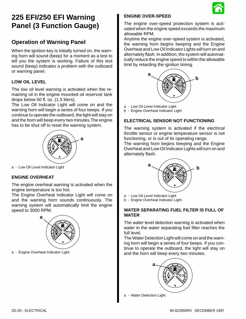
225 EFI/250 EFI WarningPanel (3 Function Gauge)
Operation of Warning PanelWhen the ignition key is initially turned on, the warn-ing horn will sound (beep) for a moment as a test totell you the system is working. Failure of this testsound (beep) indicates a problem with the outboardor warning panel.
LOW OIL LEVEL
The low oil level warning is activated when the re-maining oil in the engine mounted oil reservoir tankdrops below 50 fl. oz. (1.5 liters).The Low Oil Indicator Light will come on and thewarning horn will begin a series of four beeps. If youcontinue to operate the outboard, the light will stay onand the horn will beep every two minutes.The enginehas to be shut off to reset the warning system.
a
a - Low Oil Level Indicator Light
ENGINE OVERHEAT
The engine overheat warning is activated when theengine temperature is too hot.The Engine Overheat Indicator Light will come onand the warning horn sounds continuously. Thewarning system will automatically limit the enginespeed to 3000 RPM.
a
a - Engine Overheat Indicator Light
ENGINE OVER-SPEED
The engine over-speed protection system is acti-vated when the engine speed exceeds the maximumallowable RPM.Anytime the engine over-speed system is activated,the warning horn begins beeping and the EngineOverheat and Low Oil Indicator Lights will turn on andalternately flash. In addition, the system will automat-ically reduce the engine speed to within the allowablelimit by retarding the ignition timing.
ab
a - Low Oil Level Indicator Lightb - Engine Overheat Indicator Light
ELECTRICAL SENSOR NOT FUNCTIONING
The warning system is activated if the electricalthrottle sensor or engine temperature sensor is notfunctioning, or is out of its operating range.The warning horn begins beeping and the EngineOverheat and Low Oil Indicator Lights will turn on andalternately flash.
ab
a - Low Oil Level Indicator Lightb - Engine Overheat Indicator Light
WATER SEPARATING FUEL FILTER IS FULL OFWATER
The water level detection warning is activated whenwater in the water separating fuel filter reaches thefull level.The Water Detection Light will come on and the warn-ing horn will begin a series of four beeps. If you con-tinue to operate the outboard, the light will stay onand the horn will beep every two minutes.
a
a - Water Detection Light
ELECTRICAL - 2D-2190-822900R3 DECEMBER 1997
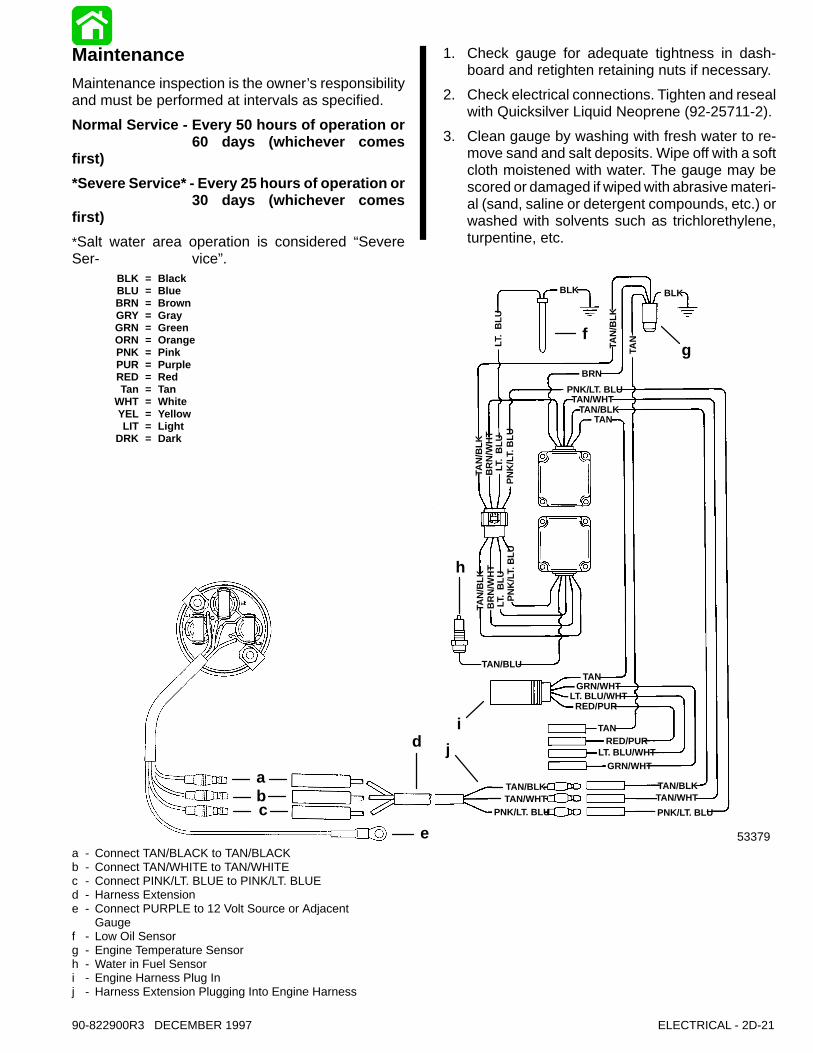
MaintenanceMaintenance inspection is the owner’s responsibilityand must be performed at intervals as specified.
Normal Service - Every 50 hours of operation or60 days (whichever comes
first)
*Severe Service* - Every 25 hours of operation or30 days (whichever comes
first)
*Salt water area operation is considered “SevereSer- vice”.
1. Check gauge for adequate tightness in dash-board and retighten retaining nuts if necessary.
2. Check electrical connections. Tighten and resealwith Quicksilver Liquid Neoprene (92-25711-2).
3. Clean gauge by washing with fresh water to re-move sand and salt deposits. Wipe off with a softcloth moistened with water. The gauge may bescored or damaged if wiped with abrasive materi-al (sand, saline or detergent compounds, etc.) orwashed with solvents such as trichlorethylene,turpentine, etc.
TAN/BLKTAN
BLKBLK
LT.
BLU
TAN
/BLK
TAN
BRN
PNK/LT. BLUTAN/WHT
TAN
/BLK
BR
N/W
HT
LT.
BLU
PN
K/L
T. B
LU
TAN
/BLK
BR
N/W
HT
LT.
BLU
PN
K/L
T. B
LU
TAN/BLU
GRN/WHTLT. BLU/WHT
RED/PURTAN
RED/PURLT. BLU/WHT
GRN/WHTTAN
TAN/BLKTAN/WHT
PNK/LT. BLU
TAN/BLKTAN/WHT
PNK/LT. BLU
BLK = BlackBLU = BlueBRN = BrownGRY = GrayGRN = GreenORN = OrangePNK = PinkPUR = PurpleRED = RedTan = Tan
WHT = WhiteYEL = YellowLIT = Light
DRK = Dark
abc
e
d j
i
h
fg
53379a - Connect TAN/BLACK to TAN/BLACKb - Connect TAN/WHITE to TAN/WHITEc - Connect PINK/LT. BLUE to PINK/LT. BLUEd - Harness Extensione - Connect PURPLE to 12 Volt Source or Adjacent
Gaugef - Low Oil Sensorg - Engine Temperature Sensorh - Water in Fuel Sensori - Engine Harness Plug Inj - Harness Extension Plugging Into Engine Harness
2D-22 - ELECTRICAL 90-822900R3 DECEMBER 1997
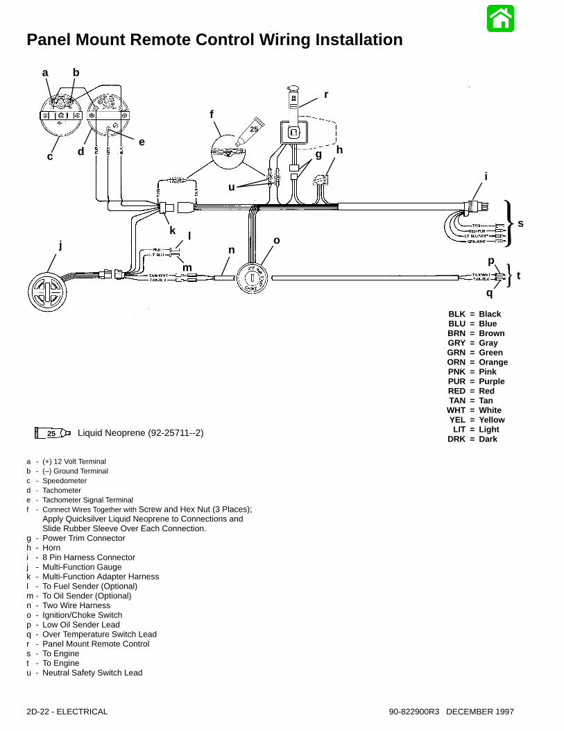
Panel Mount Remote Control Wiring Installation
BLK = BlackBLU = BlueBRN = BrownGRY = GrayGRN = GreenORN = OrangePNK = PinkPUR = PurpleRED = RedTAN = Tan
WHT = WhiteYEL = YellowLIT = Light
DRK = Dark
a b
c d
f
g h
r
ui
s
tp
q
on
m
lkj
e
Liquid Neoprene (92-25711--2)
25
25
a - (+) 12 Volt Terminal b - (–) Ground Terminalc - Speedometerd - Tachometere - Tachometer Signal Terminalf - Connect Wires Together with Screw and Hex Nut (3 Places);
Apply Quicksilver Liquid Neoprene to Connections and Slide Rubber Sleeve Over Each Connection.
g - Power Trim Connectorh - Horni - 8 Pin Harness Connectorj - Multi-Function Gaugek - Multi-Function Adapter Harnessl - To Fuel Sender (Optional)m - To Oil Sender (Optional)n - Two Wire Harnesso - Ignition/Choke Switchp - Low Oil Sender Leadq - Over Temperature Switch Leadr - Panel Mount Remote Controls - To Enginet - To Engineu - Neutral Safety Switch Lead
ELECTRICAL - 2D-2390-822900R3 DECEMBER 1997
Side Mount Remote Control Wiring Installation
BLK = BlackBLU = BlueBRN = BrownGRY = GrayGRN = GreenORN = OrangePNK = PinkPUR = PurpleRED = RedTAN = Tan
WHT = WhiteYEL = YellowLIT = Light
DRK = Dark
a b
c de
jf
gh
r
s
p
q
o
nmk
l
i
25
Liquid Neoprene (92-25711--2)25
a - (+) 12 Volt Terminal b - (–) Ground Terminalc - Speedometerd - Tachometere - Tachometer Signal Terminalf - Tachometer Receptacleg - Side Mount Remote Controlh - 8 Pin Harness Connectori - Multi-Function Gaugej - Multi-Function Adapter Harnessk - To Fuel Sender (Optional)l - To Oil Sender (Optional)m - Cable Lead (Jumper) (84-11149A3)n - Connect Wires Together with Screw and
Hex Nut; Apply Quicksilver Liquid Neoprene to Connec-tions and Slide Rubber Sleeve Over Each Connection
o - Two Wire Harnessp - Low Oil Sender Leadq - Over Temperature Switch Leadr - To Engines - To Engine
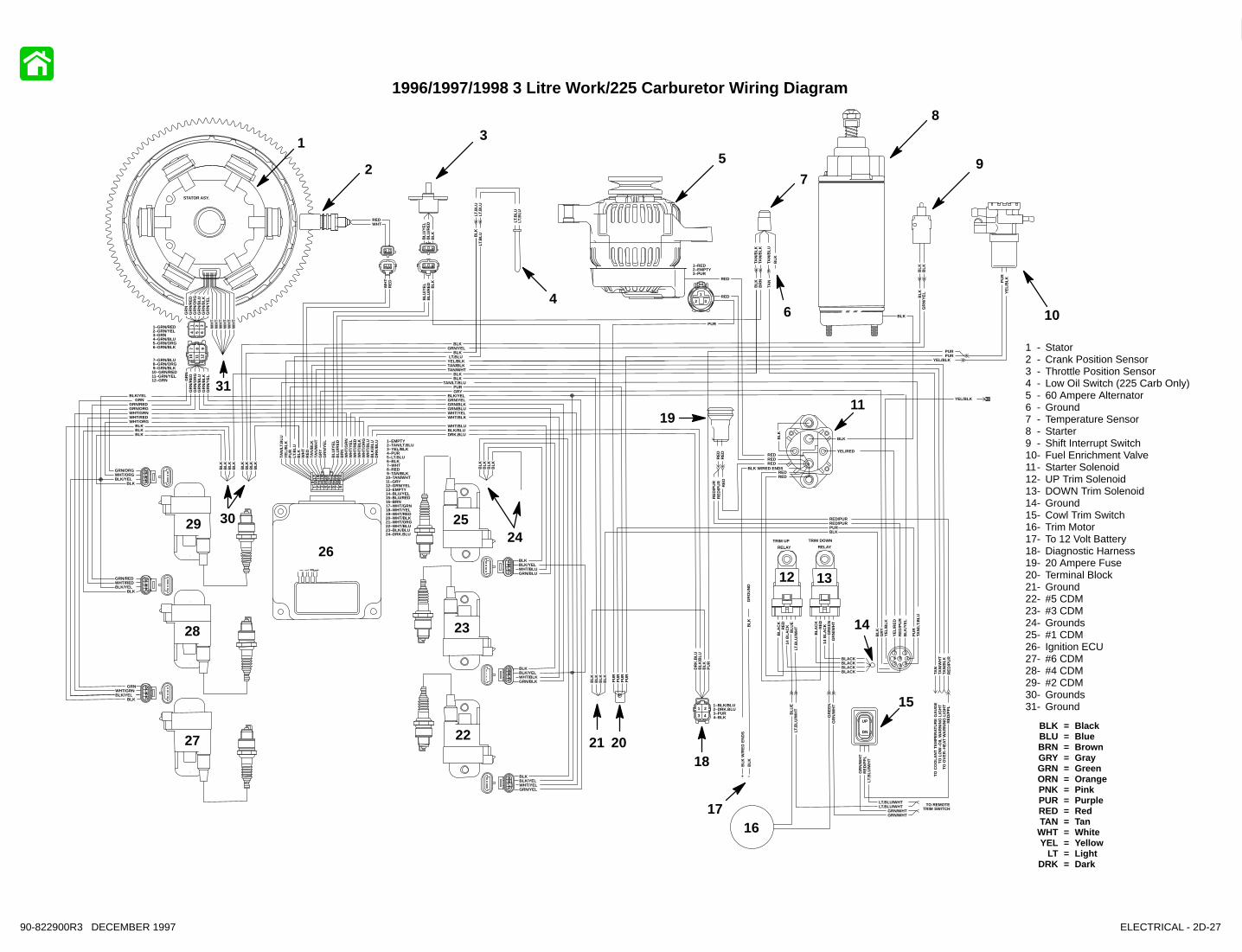
BLK = BLACKBLU = BLUEBRN = BROWNGRY = GRAYGRN = GREENPUR = PURPLERED = REDTAN = TANVIO = VIOLETWHT = WHITEYEL = YELLOW
1 - Starter2 - Ignition Stator3 - Flywheel4 - Crank Position Sensor5 - 60 Ampere Alternator6 - Low Oil Sensor7 - Throttle Position Sensor8 - Overheat Sensor9 - Fuel Enrichment Valve10- Terminal Block11- 20 Ampere Fuse12- Cowl Trim Switch13- To Trim Solenoids14- To Remote Control Harness15- Engine Harness Plug16- 12 Volt Battery17- Starter Solenoid
18- Electronic Control Module (ECM)19- Shift Interrupt Switch20- Starboard Ignition Modules - 1,3,521- Port Ignition Modules - 2,4,622- Ignition Stator
52163
1
23
4
5
6
7
8
9
10
11 12 1314
15
16
17
18
19
2021
2D-24 - ELECTRICAL 90-822900R3 DECEMBER 1997
1994 225 Wiring Diagram
ELECTRICAL - 2D-2590-822900R3 DECEMBER 1997
TAN
/LT.
BLU
PU
RLT
.BLU
BLK
WH
TR
ED
TAN
/BLK
TAN
/WH
TG
RY
GR
N/Y
EL
BLU
/YE
LB
LU/R
ED
BR
NW
HT
/GR
NW
HT
/YE
LW
HT
/RE
DW
HT
/BLK
WH
T/O
RG
WH
T/B
LUB
LK/B
LUD
RK
/BLU
BLK/YELWHT
GRN
BLK/YELWHT/BLUGRN/BLU
WHTGRN
BLK/YEL
GRN/BLKWHT/BLKBLK/YEL
WHTGRN
BLK/YEL
GRN/YELWHT/YELBLK/YEL
BLK/YELWHTGRN
BLK/YELWHT/GRN
GRN
WHT/REDGRN/RED
BLK/YEL BLK/YELWHTGRN
WHT/ORNGRN/ORG
BLK/YEL BLK/YELWHTGRN
GRN/ORNGRN/RED
GRN
WHT/ORNWHT/REDWHT/GRN
WHT/BLU
WHT/BLKWHT/YELGRN/BLUGRN/BLKGRN/YEL
REDWHT
GR
NG
RN
/RE
DG
RN
/OR
NG
RN
/BLU
GR
N/B
LKG
RN
/YE
L
BLU
/YE
LB
LU/R
ED
BLK
BLU
/YE
LB
LU/R
ED
BLK
WH
TR
ED
BLK/YEL BLK/YEL
TAN
/BLK
TAN
/BLK
BLK
TAN
/BLU
BR
NB
LK
TAN
BLK
BLK
12
34567
8
BLK
BLK
GRN/WHT
LT.BLU/WHT
RE
D
BLK
GR
YY
EL/
BLK
YE
L/R
ED
RE
D/P
UR
BLK
/YE
L
PU
RTA
N/L
T.B
LU
YEL/RED
PU
R
GRYPUR
TAN/LT.BLU
BLK
GRN/WHTBLKPUR
BLKBLK
TAN/WHTTAN/BLK
RE
DR
ED
RE
D/P
UR
RE
D/P
UR
RED/PURRED/PUR
RE
D
BLK/BLUDRK.BLU
DR
K.B
LUB
LK/B
LUB
LKP
UR
YEL/BLKLT.BLU
LT.B
LU/W
HT
RE
D/P
UR
RED
RED
PUR
RE
D
TAN
/WH
TTA
N/B
LK
TAN
DN
UP
LT.B
LU/W
HT
GR
N/W
HT
RE
D/P
UR
LT.B
LU/W
HT
RE
D/P
UR
GR
N/W
HT
LT.BLU/WHT
GRN/WHTGRN/WHT
LT.BLU/WHT
BLK
BLK
BLK
BLK
BLK BLK
BLKGRN/YEL
BLK
BLK
GR
NG
RN
/RE
DG
RN
/OR
NG
RN
/BLU
GR
N/B
LKG
RN
/YE
LW
HT
BLK
BLK
BLK
GR
N/Y
EL
REDREDREDBLK
RED
BLK
BLK
BLK
BLK
+ –
BLK
BLU
GR
N
LT.B
LULT
.BLU
BLK
LT.B
LU
LT.B
LULT
.BLU
1 2 3
4 5 6
7 8 9
10 11 12
1–GRN/RED 2–GRN/YEL 3–GRN 4–GRN/BLU 5–GRN/ORN 6–GRN/BLK
7–GRN/BLU 8–GRN/ORN 9–GRN/BLK10–GRN/RED11–GRN/YEL12–GRN
1 2
3 4
1–BLK/BLU2–DRK.BLU3–PUR4–BLK
1 2 3 4 5 6 7 8
9 10 11 12 13 14 15 16
17 18 19 20 21 22 23 24
1– 2–TAN/LT.BLU 3–YEL/BLK 4–PUR 5–LT.BLU 6–BLK 7–WHT 8–RED 9–TAN/BLK10–TAN/WHT11–GRY12–GRN/YEL13–14–BLU/YEL15–BLU/RED16–BRN17–WHT/GRN18–WHT/YEL19–WHT/RED20–WHT/BLK21–WHT/ORN22–WHT/BLU23–BLK/BLU24–DRK.BLU
1
2 3
1–RED2–3–PUR
WH
TW
HT
WH
TW
HT
WH
T
BLK
BLK
BLK
BLK
BLK
BLK
BLK PU
RP
UR
PU
R
YE
L/B
LK
PU
RY
EL/
BLK
PURPUR
YEL/BLK
YEL/BLK
GR
N/W
HT
BLK = BlackBLU = BlueBRN = BrownGRY = GrayGRN = GreenORN = OrangePNK = PinkPUR = PurpleRED = RedTAN = Tan
WHT = WhiteYEL = Yellow
LT = LightDRK = Dark
1 - Stator2 - Crank Position Sensor3 - Throttle Position Sensor4 - Low Oil Switch (225 Carb Only)5 - 60 Ampere Alternator6 - Temperature Sensor7 - Starter8 - Shift Interrupt Switch9 - Fuel Enrichment Valve10- Starter Solenoid11- UP Trim Solenoid12- DOWN Trim Solenoid13- Cowl Trim Switch14- Trim Motor15- 20 Ampere Fuse16- #1 Capacitor Discharge Module17- #3 Capacitor Discharge Module18- #5 Capacitor Discharge Module19- Electronic Control Module20- #2 Capacitor Discharge Module21- #4 Capacitor Discharge Module22- #6 Capacitor Discharge Module
1995 3 Litre Work/225 Carb Wiring Diagram
1
2
3
4
56
7
8
9
10
11
15
12
13
14
18
17
1620
21
22
19
TAN
/LT.
BLU
PU
RB
RN
/WH
TB
LKW
HT
RE
DTA
N/B
LKTA
N/W
HT
GR
YG
RN
/YE
LG
RY
/WH
TB
LU/Y
EL
BLU
/RE
DB
RN
WH
T/G
RN
WH
T/Y
EL
WH
T/R
ED
WH
T/B
LKW
HT
/OR
NW
HT
/BLU
BLK
/BLU
DR
K/B
LU
BLK/YELWHT
GRN
BLK/YELWHT/BLUGRN/BLU
WHTGRN
BLK/YEL
GRN/BLKWHT/BLKBLK/YEL
WHTGRN
BLK/YEL
GRN/YELWHT/YELBLK/YEL
BLK/YELWHTGRN
BLK/YELWHT/GRN
GRN
WHT/REDGRN/RED
BLK/YEL BLK/YELWHTGRN
WHT/ORNGRN/ORN
BLK/YEL BLK/YELWHTGRN
GRN/ORNGRN/RED
GRN
WHT/ORNWHT/REDWHT/GRN
WHT/BLU
WHT/BLKWHT/YELGRN/BLUGRN/BLKGRN/YEL
REDWHT
GR
NG
RN
/RE
DG
RN
/OR
NG
RN
/BLU
GR
N/B
LKG
RN
/YE
L
BLU
/YE
LB
LU/R
ED
BLK
BLU
/YE
LB
LU/R
ED
BLK
WH
TR
ED
BLK/YEL BLK/YEL
TAN
/BLK
TAN
/BLK
BLK
TAN
/BLU
BR
NB
LK
TAN
TAN
/BLK
BLK
BLK
12
34567
8
BLK
BLK
GRN/WHT
LT.BLU/WHT
RE
D
BLK
GR
Y
YE
L/R
ED
RE
D/P
PL
BLK
/YE
L
PU
RTA
N/L
T.B
LU
YEL/RED
PU
R
GRYPUR
TAN/LT.BLU
BLK
GRN/WHTBLKPUR
BLKBLK
TAN/WHTTAN/BLK
RE
DR
ED
RE
D/P
UR
RE
D/P
UR
RED/PURRED/PUR
RE
D
BLK/BLUDRK.BLU
LT.B
LUB
RN
/WH
TP
NK
/LT.
BLU
WH
T/O
RN
BLU
/YE
LB
LU/R
ED
GR
Y/W
HT
GR
YW
HT
/BLU
TAN
/BLK
DR
K.B
LUB
LK/B
LU
DR
K.B
LUB
LK/B
LUB
LKP
UR
GRY/WHTBRN/WHT
WHT/ORN
PNK/LT.BLU
LT.B
LU/W
HT
GR
N/W
HT
PIK
/LT.
BLU
RE
D/P
UR
RED
RED
PUR
RE
D
TAN
/WH
TTA
N/B
LK
TAN
DR
K.B
LU/W
HT
BLK
/BLUTA
NB
LKW
HT
/BLU
PN
K/L
T.B
LUB
LK/W
HT
TAN
/BLK
BLU
/RE
DB
LU/Y
EL
GR
Y/W
HT
TAN
/BLU
BR
N/W
HT
DR
K.B
LUR
ED
/PU
RG
RY
WH
T/G
RN
BLK
LT.B
LUPU
RW
HT
YE
LB
LK/W
HT
BLK PU
RP
UR
BLK/WHTBLK/WHT
BLK
WH
T/G
RN
BLU
/YE
L
TAN
BLK
TAN
BLK
RE
D/P
UR
RE
D
YE
LW
HT
DR
K.B
LUR
ED
RE
DD
RK
.BLU WH
TY
EL
PURBLK
GRY/WHTWHT/ORN DRK.BLU/WHT
DR
K.B
LU/W
HT
DN
UP
LT.B
LU/W
HT
GR
N/W
HT
RE
D/P
UR
LT.B
LU/W
HT
RE
D/P
UR
GR
N/W
HT
LT.BLU/WHT
GRN/WHTGRN/WHT
LT.BLU/WHT
BLK
BLK
BLK
BLK
BLK BLK
WH
T/O
RN
PN
K/L
T.B
LU
BLU
/YE
L
BR
N/W
HT
BLU
/RE
D
LT.B
LU
GR
Y/W
HT
GR
YW
HT
/BLU
TAN
/BLK
DR
K.B
LU/W
HT
BLK
/BLU
BLKGRN/YEL
BLK
BLK
GR
NG
RN
/RE
DG
RN
/OR
NG
RN
/BLU
GR
N/B
LKG
RN
/YE
LW
HT
TAN
/BLU
BLK
BLK
BLK
GR
N/Y
EL
REDREDRED
BLK RED
BLK
REDRED
BLK
BLK
BLK
+ –
BLK
BLU
GR
N
LT.B
LULT
.BLU
BLK
LT.B
LU
LT.B
LULT
.BLU
1 2 3
4 5 6
7 8 9
10 11 12
1–GRN/RED 2–GRN/YEL 3–GRN 4–GRN/BLU 5–GRN/ORN 6–GRN/BLK
7–GRN/BLU 8–GRN/ORN 9–GRN/BLK10–GRN/RED11–GRN/YEL12–GRN
1 2 3 4 5 6
7 8 9 10 11 12
13 14 15 16 17 18
19 20 21 22 23 24 1–BLU/RED 2–BLU/YEL 3–WHT/ORN 4–PNK/LT.BLU 5–BRN/WHT 6–LT.BLU 7–BLK/BLU 8–DRK/BLU 9–TAN/BLK10–WHT/BLU11–GRY12–GRY/WHT13–BLK/BLU14–DRK.BLU15–TAN/BLK16–WHT/BLU17–GRY18–GRY/WHT19–BLU/RED20–BLU/YEL21–WHT/ORN22–PNK/LT.BLU23–BRN/WHT24–LT.BLU
1 2
3 4
1–BLK/BLU2–DRK.BLU3–PUR4–BLK
123
456 1–DRK.BLU/WHT 2–GRY/WHT 3–PUR 4– 5–WHT/ORN 6–BLK
1 2 3 4 5 6 7 8
9 10 11 12 13 14 15 16
17 18 19 20 21 22 23 24
1– 2–TAN/LT.BLU 3– 4–PUR 5–BRN/WHT 6–BLK 7–WHT 8–RED 9–TAN/BLK10–TAN/WHT11–GRY12–GRN/YEL13–GRY/WHT14–BLU/YEL15–BLU/RED16–BRN17–WHT/GRN18–WHT/YEL19–WHT/RED20–WHT/BLK21–WHT/ORN22–WHT/BLU23–BLK/BLU24–DRK.BLU
9
8 7 6
1011
5 4 3 2 1
1516
17182021222324
121314
1–BLK/WHT 2–YEL 3–WHT 4–PUR 5–LT.BLU 6–BLK 7–WHT/GRN 8–GRY 9–RED/PUR10–DRK.BLU11–BRN/WHT12–TAN/BLU13–GRY/WHT14–BLU/YEL15–BLU/RED16–TAN/BLK17–BLK/WHT18–PNK/LT.BLU19–20–WHT/BLU21–BLK22–TAN23–BLU/BLK24–DRK.BLU/WHT
1
2 3
1–RED2–3–PUR
1 234
314
2
WH
TW
HT
WH
TW
HT
WH
T
BLK
BLK
BLK
BLK
BLK
BLK
BLK
BLK
BLK
BLK
BLK
PU
RP
UR
PU
R
BLK = BlackBLU = BlueBRN = BrownGRY = GrayGRN = GreenORN = OrangePNK = PinkPUR = PurpleRED = RedTAN = Tan
WHT = WhiteYEL = Yellow
LT = LightDRK = Dark
StatorCrank Position SensorThrottle Position SensorLow Oil Switch60 Ampere AlternatorTemperature SensorStarterShift Interrupt Switch#1 Fuel Injector#2 Fuel Injector#3 Fuel Injector#4 Fuel Injector#5 Fuel Injector#6 Fuel InjectorFuel PumpWater SensorDetonation Module Harness (Not Used)Knock Sensor Harness (Not Used)Trim MotorCowl Trim SwitchDOWN Trim SolenoidUP T rim SolenoidStarter Solenoid20 Ampere FuseMAP SensorAir Temperature Sensor#5 CDM#3 CDM#1 CDMIgnition ECMEFI (Fuel) ECM#6 CDM#4 CDM#2 CDM
1995 225 EFI Wiring Diagram
WHT/BLU
1
2
3
4
5
6
7
8
9
10
11
12
13
14
15
16
17
18
19
20
21
22
23
24
25
26
27
28
29
30
31
32
33
34
26 ELECTRICAL 90-822900R3 DECEMBER 1997
ELECTRICAL - 2D-2790-822900R3 DECEMBER 1997
BLK = BlackBLU = BlueBRN = BrownGRY = GrayGRN = GreenORN = OrangePNK = PinkPUR = PurpleRED = RedTAN = Tan
WHT = WhiteYEL = Yellow
LT = LightDRK = Dark
1 - Stator2 - Crank Position Sensor3 - Throttle Position Sensor4 - Low Oil Switch (225 Carb Only)5 - 60 Ampere Alternator6 - Ground7 - Temperature Sensor8 - Starter9 - Shift Interrupt Switch10- Fuel Enrichment Valve11- Starter Solenoid12- UP Trim Solenoid13- DOWN Trim Solenoid14- Ground15- Cowl Trim Switch16- Trim Motor17- To 12 Volt Battery18- Diagnostic Harness19- 20 Ampere Fuse20- Terminal Block21- Ground22- #5 CDM23- #3 CDM24- Grounds25- #1 CDM26- Ignition ECU27- #6 CDM28- #4 CDM29- #2 CDM30- Grounds31- Ground
1996/1997/1998 3 Litre Work/225 Carburetor Wiring Diagram
TAN
/LT.
BLU
PU
RLT
.BLU
BLK
WH
TR
ED
TAN
/BLK
TAN
/WH
TG
RY
GR
N/Y
EL
BLU
/YE
LB
LU/R
ED
BR
NW
HT
/GR
NW
HT
/YE
LW
HT
/RE
DW
HT
/BLK
WH
T/O
RG
WH
T/B
LUB
LK/B
LUD
RK
/BLU
GRN/ORGGRN/RED
GRN
WHT/ORGWHT/REDWHT/GRN
WHT/BLU
WHT/BLKWHT/YELGRN/BLUGRN/BLKGRN/YEL
REDWHT
GR
NG
RN
/RE
DG
RN
/OR
GG
RN
/BLU
GR
N/B
LKG
RN
/YE
L
BLU
/YE
LB
LU/R
ED
BLK
BLU
/YE
LB
LU/R
ED
BLK
WH
TR
ED
BLK/YEL BLK/YEL
TAN
/BLK
TAN
/BLK
BLK
TAN
/BLU
BR
NB
LK
TAN
BLK
BLK
12
34567
8
BLK
GR
YY
EL/
BLK
YE
L/R
ED
RE
D/P
UR
BLK
/YE
L
PU
RTA
N/L
T.B
LU
YEL/RED
PU
R
GRYPUR
TAN/LT.BLU
BLK
BLKPUR
TAN/WHTTAN/BLK
RE
DR
ED
RE
D/P
UR
RE
D/P
UR
RED/PURRED/PUR
RE
D
BLK/BLUDRK.BLU
DR
K.B
LUB
LK/B
LUB
LKP
UR
YEL/BLKLT.BLU
RE
D/P
UR
RED
RED
PUR
TAN
/WH
TTA
N/B
LK
TAN
STATOR ASY.
TO
CO
OLA
NT
TE
MP
ER
ATU
RE
GA
UG
ET
O L
OW
–OIL
WA
RN
ING
LIG
HT
TO
OV
ER
–HE
AT W
AR
NIN
G L
IGH
T
GR
OU
ND
GRN/YEL
GR
NG
RN
/RE
DG
RN
/OR
GG
RN
/BLU
GR
N/B
LKG
RN
/YE
LW
HT
BLK
BLK
BLK
GR
N/Y
EL
REDREDRED
BLK W/RED ENDS
BLK
BLK
BLK
BLK
W/R
ED
EN
DS
+ –
LT.B
LULT
.BLU
BLK
LT.B
LU
LT.B
LULT
.BLU
1 2 3
4 5 6
7 8 9
10 11 12
1–GRN/RED 2–GRN/YEL 3–GRN 4–GRN/BLU 5–GRN/ORG 6–GRN/BLK
7–GRN/BLU 8–GRN/ORG 9–GRN/BLK10–GRN/RED11–GRN/YEL12–GRN
1 2
3 4
1–BLK/BLU2–DRK.BLU3–PUR4–BLK
1 2 3 4 5 6 7 8
9 10 11 12 13 14 15 16
17 18 19 20 21 22 23 24
1–EMPTY 2–TAN/LT.BLU 3–YEL/BLK 4–PUR 5–LT.BLU 6–BLK 7–WHT 8–RED 9–TAN/BLK10–TAN/WHT11–GRY12–GRN/YEL13–EMPTY14–BLU/YEL15–BLU/RED16–BRN17–WHT/GRN18–WHT/YEL19–WHT/RED20–WHT/BLK21–WHT/ORG22–WHT/BLU23–BLK/BLU24–DRK.BLU
1
2 3
1–RED2–EMPTY3–PUR
WH
TW
HT
WH
TW
HT
WH
T
BLK
BLK
BLK PU
RP
UR
PU
R
YE
L/B
LK
PU
RY
EL/
BLK
PURPUR
YEL/BLK
YEL/BLK
RED
DN
UP
LT.B
LU/W
HT
GR
N/W
HT
RE
D/P
PL
LT.B
LU/W
HT
RE
D/P
PL
GR
N/W
HT
LT.BLU/WHT
GRN/WHTGRN/WHT
LT.BLU/WHT
BLACK
LT.B
LU/W
HT
BLU
E
14 B
LAC
KRE
DB
LAC
K
GR
N/W
HT
GR
EE
N
14 B
LAC
KRE
DB
LAC
K
TRIM UP
RELAY
TRIM DOWN
RELAY
BLACK
BLACKBLACK
TO REMOTETRIM SWITCH
GR
EE
N
BLU
E
RED
BLK/YELWHT/BLUGRN/BLU
GRN/BLKWHT/BLKBLK/YEL
GRN/YELWHT/YELBLK/YEL
WHT/GRNGRN
WHT/REDGRN/RED
BLK/YEL
WHT/ORGGRN/ORG
BLK/YEL
BLKBLK
BLK
BLK
BLK
BLK
BLK
ABCD
BLK
BLK
BLK
BLK
BLK
BLKBLKBLK
ABCD
ABCD
BLK
BLKBLK/YEL
ABCD
DCBA
DCBA
BLK
BLK
BLK
BLK
BLK
BLK
BLK
BLK
1
2
3
4
5
6
7
8
9
10
11
12 13
14
15
1617
18
19
202122
23
2425
26
27
28
29 30
31

BLK = BlackBLU = BlueBRN = BrownGRY = GrayGRN = GreenORN = OrangePNK = PinkPUR = PurpleRED = RedTAN = Tan
WHT = WhiteYEL = Yellow
LT = LightDRK = Dark
StatorCrank Position SensorThrottle Position SensorLow Oil Switch60 Ampere AlternatorTemperature SensorStarterShift Interrupt Switch#1 Fuel Injector#2 Fuel Injector#3 Fuel Injector#4 Fuel Injector#5 Fuel Injector#6 Fuel InjectorFuel PumpMap SensorWater SensorAir Temperature SensorTo Remote Trim SwitchCowl Trim SwitchRemote Control HarnessDOWN Trim SolenoidUP Trim SolenoidStarter Solenoid20 Ampere FuseDiagnostic HarnessTo 12 Volt BatteryTrim MotorTerminal Block#5 CDM#3 CDM#1 CDMGroundEFI (Fuel) ECMIgnition ECM#6 CDM#4 CDM#2 CDM
1996/1997/1998 225 EFI/250 EFI Wiring Diagram
TAN
/LT.
BLU
PU
RB
RN
/WH
TB
LKW
HT
RE
DTA
N/B
LKTA
N/W
HT
GR
YG
RN
/YE
LG
RY
/WH
TB
LU/Y
EL
BLU
/RE
DB
RN
WH
T/G
RN
WH
T/Y
EL
WH
T/R
ED
WH
T/B
LKW
HT
/OR
GW
HT
/BLU
BLK
/BLU
DR
K/B
LU
BLK/YELWHT/BLUGRN/BLU
GRN/BLKWHT/BLKBLK/YEL
GRN/YELWHT/YELBLK/YEL
WHT/GRNGRN
WHT/REDGRN/RED
BLK/YEL
WHT/ORGGRN/ORG
BLK/YEL
GRN/ORGGRN/RED
GRN
WHT/ORGWHT/REDWHT/GRN
WHT/BLU
WHT/BLKWHT/YELGRN/BLUGRN/BLKGRN/YEL
REDWHT
GR
NG
RN
/RE
DG
RN
/OR
GG
RN
/BLU
GR
N/B
LKG
RN
/YE
L
BLU
/YE
LB
LU/R
ED BLK
BLU
/YE
LB
LU/R
ED
BLK
WH
TR
ED
BLK/YEL BLK/YEL
TAN
/BLK
TAN
/BLK
BLA
CK
TAN
/BLU
BR
NB
LK
TAN
TAN
/BLK
BLK
BLK
YEL/RED
PU
R
GRYPUR
TAN/LT.BLU
BLK
BLKPUR
BLKBLK
TAN/WHTTAN/BLK
RE
DR
ED
RE
D/P
UR
RE
D/P
UR
RED/PURRED/PUR
RE
D
BLK/BLUDRK.BLU
LT.B
LUB
RN
/WH
TP
NK
/LT.
BLU
WH
T/O
RG
BLU
/YE
LB
LU/R
ED
GR
Y/W
HT
GR
YW
HT
/BLU
TAN
/BLK
DR
K.B
LUB
LK/B
LU
DR
K.B
LUB
LK/B
LUB
LKP
UR
GRY/WHTBRN/WHT
WHT/ORG
PNK/LT.BLU
RED
RED
PUR
DR
K.B
LU/W
HT
BLK
/BLUTA
NB
LKW
HT
/BLU
PN
K/L
T.B
LUB
LK/W
HT
TAN
/BLK
BLU
/RE
DB
LU/Y
EL
GR
Y/W
HT
TAN
/BLU
BR
N/W
HT
DR
K.B
LUR
ED
/PP
LGR
YW
HT
/GR
NB
LKLT
.BLUP
UR
WH
TY
EL
BLK
/WH
T
BLK PU
R
BLK/WHTBLK/WHT
BLK
WH
T/G
RN
BLU
/YE
L
TAN
BLK
TAN
BLK
RE
D/P
UR
RE
D
YE
LW
HT
DR
K.B
LUR
ED
RE
DD
RK
.BLU W
HT
YE
L
DIAGNOSTICDEVICE
PN
K/L
T.B
LU
BLU
/YE
L
BR
N/W
HT
BLU
/RE
D
LT.B
LU
GR
Y/W
HT
GR
YW
HT
/BLU
TAN
/BLK
DR
K.B
LU/W
HT
BLK
/BLU
GR
OU
ND
GR
OU
ND
BLKGRN/YEL
BLKB
LK
GR
NG
RN
/RE
DG
RN
/OR
GG
RN
/BLU
GR
N/B
LKG
RN
/YE
LW
HT
TAN
/BLU
BLA
CK
BLA
CK
BLK
GR
N/Y
EL
REDREDRED
BLK W/RED ENDSRED
BLK
REDRED
BLK
BLK
BLK
W/R
ED
EN
DS
+ –
LT.B
LULT
.BLU
BLK
LT.B
LU
LT.B
LULT
.BLU
1 2 3
4 5 6
7 8 9
10 11 12
1–GRN/RED 2–GRN/YEL 3–GRN 4–GRN/BLU 5–GRN/ORG 6–GRN/BLK
7–GRN/BLU 8–GRN/ORG 9–GRN/BLK10–GRN/RED11–GRN/YEL12–GRN
1 2 3 4 5 6
7 8 9 10 11 12
13 14 15 16 17 18
19 20 21 22 23 24
1–BLU/RED 2–BLU/YEL 3–WHT/ORG 4–PNK/LT.BLU 5–BRN/WHT 6–LT.BLU 7–BLK/BLU 8–DRK/BLU 9–TAN/BLK10–WHT/BLU11–GRY12–GRY/WHT13–BLK/BLU14–DRK.BLU15–TAN/BLK16–WHT/BLU17–GRY18–GRY/WHT19–BLU/RED20–BLU/YEL21–PLUG22–PNK/LT.BLU23–BRN/WHT24–LT.BLU
1 2
3 4
1–BLK/BLU2–DRK.BLU3–PUR4–BLK
1 2 3 4 5 6 7 8
9 10 11 12 13 14 15 16
17 18 19 20 21 22 23 24 1–EMPTY 2–TAN/LT.BLU 3–EMPTY 4–PUR 5–BRN/WHT 6–BLK 7–WHT 8–RED 9–TAN/BLK10–TAN/WHT11–GRY12–GRN/YEL13–GRY/WHT14–BLU/YEL15–BLU/RED16–BRN17–WHT/GRN18–WHT/YEL19–WHT/RED20–WHT/BLK21–WHT/ORG22–WHT/BLU23–BLK/BLU24–DRK.BLU
9
8 7 6
1011
5 4 3 2 1
1516
1718192021222324
121314
1–BLK/WHT 2–YEL 3–WHT 4–PUR 5–LT.BLU 6–BLK 7–WHT/GRN 8–GRY 9–RED/PPL10–DRK.BLU11–BRN/WHT12–TAN/BLU13–GRY/WHT14–BLU/YEL15–BLU/RED16–TAN/BLK17–BLK/WHT18–PNK/LT.BLU19–EMPTY20–WHT/BLU21–BLK22–TAN23–BLU/BLK24–DRK.BLU/WHT
1
2 3
1–RED2–EMPTY3–PUR
1 234
576
8
WH
TW
HT
WH
TW
HT
WH
T
BLK
BLK
BLK
BLK
BLK
BLK
BLK
BLK
BLK PU
RP
UR
PU
R
12
34
56
78
BLA
CK
GR
AYY
EL/
BLK
YE
L/R
ED
RE
D/P
PL
BLK
/YE
L
PU
RP
LETA
N/L
T.B
LU
PIN
K/L
T.B
LUR
ED
/PP
L
TAN
/WH
TTA
N/B
LK
TAN
DN
UP
TO C
OO
LAN
T T
EM
PE
RAT
UR
E G
AU
GE
TO L
OW
–OIL
WA
RN
ING
LIG
HT
TO O
VE
R–H
EAT
WA
RN
ING
LIG
HT
TO W
ATE
R IN
DIC
ATO
R W
AR
NIN
G L
IGH
T
LT.B
LU/W
HT
GR
N/W
HT
RE
D/P
PL
LT.B
LU/W
HT
RE
D/P
PL
GR
N/W
HT
LT.BLU/WHT
GRN/WHTGRN/WHT
LT.BLU/WHT
BLACK
NO
CO
NN
EC
TIO
N
LT.B
LU/W
HTBLU
E
14 B
LAC
KRE
DB
LAC
K
GR
N/W
HT
GR
EE
N
14 B
LAC
KRE
DB
LAC
K
TRIM UP
RELAY
TRIM DOWN
RELAY
BLACK
BLACKBLACK
GR
EE
N
BLU
E
REDABCD
BLK
BLK
BLK
BLK
BLK
BLKBLKBLK
ABCD
ABCD
BLK
BLKBLK/YEL
ABCD
DCBA
DCBA
BLK
BLK
BLK
BLK
BLK
BLK
BLK
12
3
4
56
7
8
9
10
11
12
13
14
15
16
17
18
19
20
21
2223
24
25
26
27
28
2930
31
32
33
34
35
36
37
38
28 ELECTRICAL 90-822900R3 DECEMBER 1997