Embed Size (px)
Citation preview

Welcome to this training module which looks at the hardware construction of an AC drive.
1
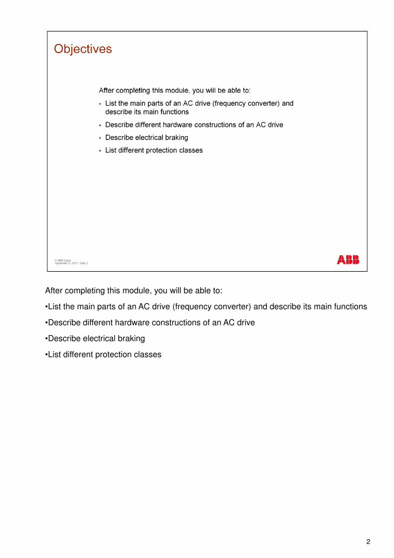
After completing this module, you will be able to:
•List the main parts of an AC drive (frequency converter) and describe its main functions
•Describe different hardware constructions of an AC drive
•Describe electrical braking
•List different protection classes
2
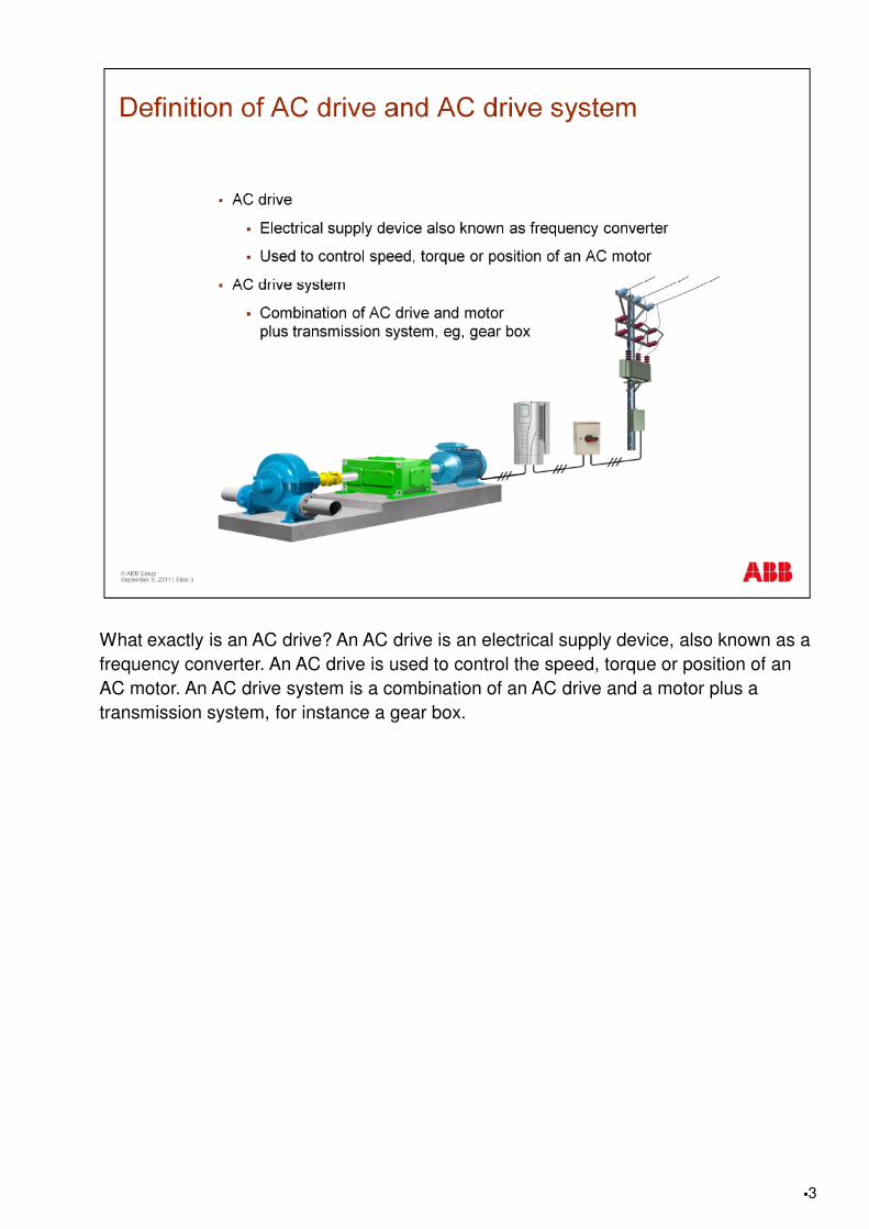
What exactly is an AC drive? An AC drive is an electrical supply device, also known as a frequency converter. An AC drive is used to control the speed, torque or position of an AC motor. An AC drive system is a combination of an AC drive and a motor plus a transmission system, for instance a gear box.
�3
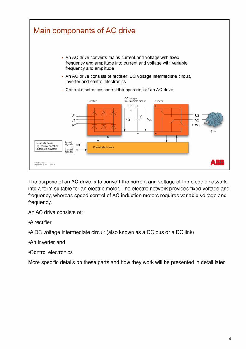
The purpose of an AC drive is to convert the current and voltage of the electric network into a form suitable for an electric motor. The electric network provides fixed voltage and frequency, whereas speed control of AC induction motors requires variable voltage and frequency.
An AC drive consists of:
•A rectifier
•A DC voltage intermediate circuit (also known as a DC bus or a DC link)•A DC voltage intermediate circuit (also known as a DC bus or a DC link)
•An inverter and
•Control electronics
More specific details on these parts and how they work will be presented in detail later.
4
A rectifier converts mains voltage with fixed frequency and amplitude into DC voltage.
There are different kinds of rectifier. In this presentation, we concentrate on the following three:
•Diode rectifier
•Thyristor rectifier
•IGBT rectifier
In the coming slides, we familiarize ourselves with these rectifiers.
5

The most common diode rectifier is called a 6-pulse diode bridge. It consists of six diodes. A diode is an electronic component that lets current flow only in one direction. When six diodes in a 3-phase supply are connected as in the figure, they form the 6-pulse diode bridge, and the output is a DC voltage.
In a diode bridge, energy (E) can flow only in one direction, from the network to the motor.
In order to increase the power and/or lower the harmonics in the supply network, diode bridges can be parallel connected. Lowering harmonics requires an additional phase shifting transformer.
The power factor of the diode bridge is close to unity.
6
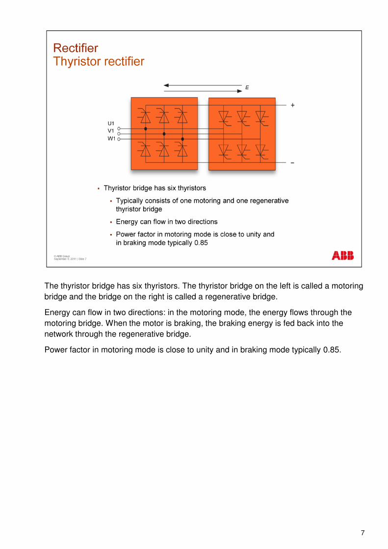
The thyristor bridge has six thyristors. The thyristor bridge on the left is called a motoring bridge and the bridge on the right is called a regenerative bridge.
Energy can flow in two directions: in the motoring mode, the energy flows through the motoring bridge. When the motor is braking, the braking energy is fed back into the network through the regenerative bridge.
Power factor in motoring mode is close to unity and in braking mode typically 0.85.
7
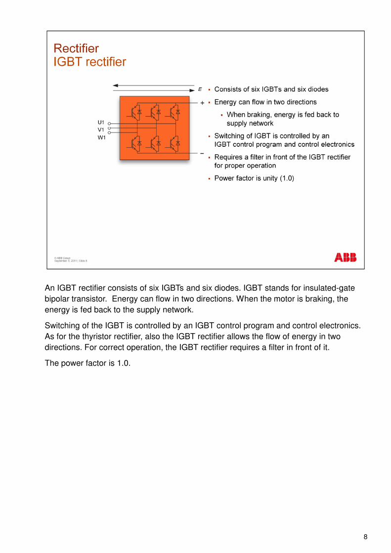
An IGBT rectifier consists of six IGBTs and six diodes. IGBT stands for insulated-gate bipolar transistor. Energy can flow in two directions. When the motor is braking, the energy is fed back to the supply network.
Switching of the IGBT is controlled by an IGBT control program and control electronics. As for the thyristor rectifier, also the IGBT rectifier allows the flow of energy in two directions. For correct operation, the IGBT rectifier requires a filter in front of it.
The power factor is 1.0.
8

The purpose of the DC voltage intermediate circuit is to act as an energy storage for the inverter as well as to provide DC voltage to the inverter unit and reactive power to the motor. The energy is stored in the capacitor (C). Additionally, the DC voltage intermediate circuit acts as a low-pass filter: it receives the pulsating voltage from the rectifier and smoothes its ripple.
9
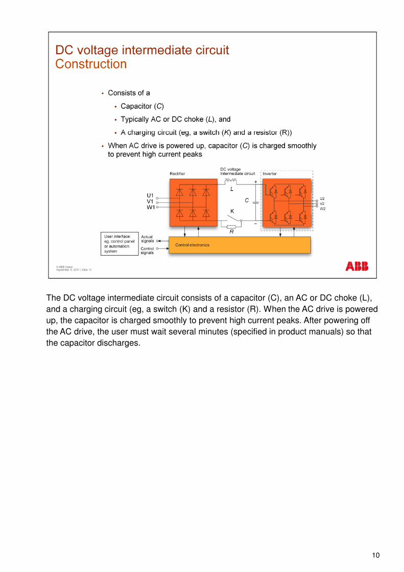
The DC voltage intermediate circuit consists of a capacitor (C), an AC or DC choke (L), and a charging circuit (eg, a switch (K) and a resistor (R). When the AC drive is powered up, the capacitor is charged smoothly to prevent high current peaks. After powering off the AC drive, the user must wait several minutes (specified in product manuals) so that the capacitor discharges.
10
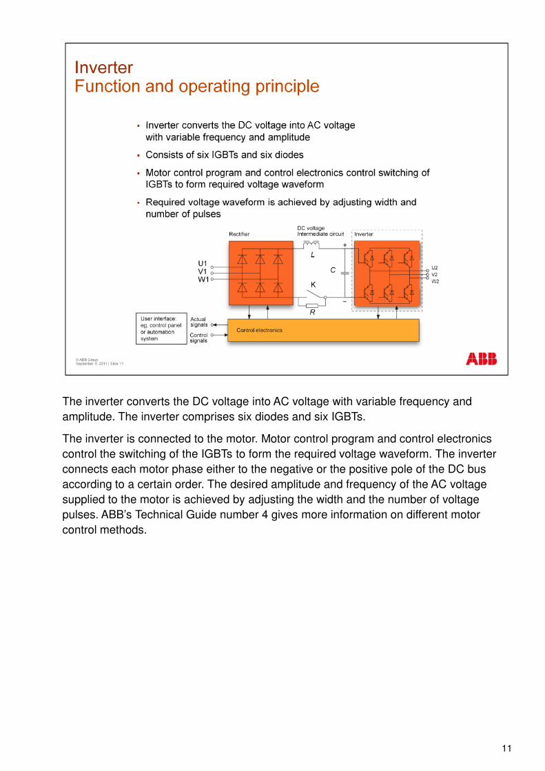
The inverter converts the DC voltage into AC voltage with variable frequency and amplitude. The inverter comprises six diodes and six IGBTs.
The inverter is connected to the motor. Motor control program and control electronics control the switching of the IGBTs to form the required voltage waveform. The inverter connects each motor phase either to the negative or the positive pole of the DC bus according to a certain order. The desired amplitude and frequency of the AC voltage supplied to the motor is achieved by adjusting the width and the number of voltage pulses. ABB’s Technical Guide number 4 gives more information on different motor pulses. ABB’s Technical Guide number 4 gives more information on different motor control methods.
11
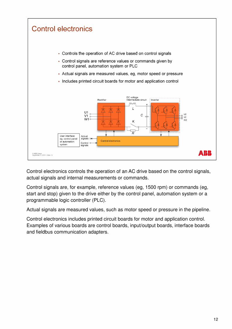
Control electronics controls the operation of an AC drive based on the control signals, actual signals and internal measurements or commands.
Control signals are, for example, reference values (eg, 1500 rpm) or commands (eg, start and stop) given to the drive either by the control panel, automation system or a programmable logic controller (PLC).
Actual signals are measured values, such as motor speed or pressure in the pipeline.
Control electronics includes printed circuit boards for motor and application control. Control electronics includes printed circuit boards for motor and application control. Examples of various boards are control boards, input/output boards, interface boards and fieldbus communication adapters.
12
There are several motor control methods. The use of a specific method is determined by the application where the drive system is used. There are different applications, for example cranes, elevators or fans. Various methods for different applications are listed here. Closed loop control means that the control method has a speed feedback. Open loop control means that the speed is not measured.
13
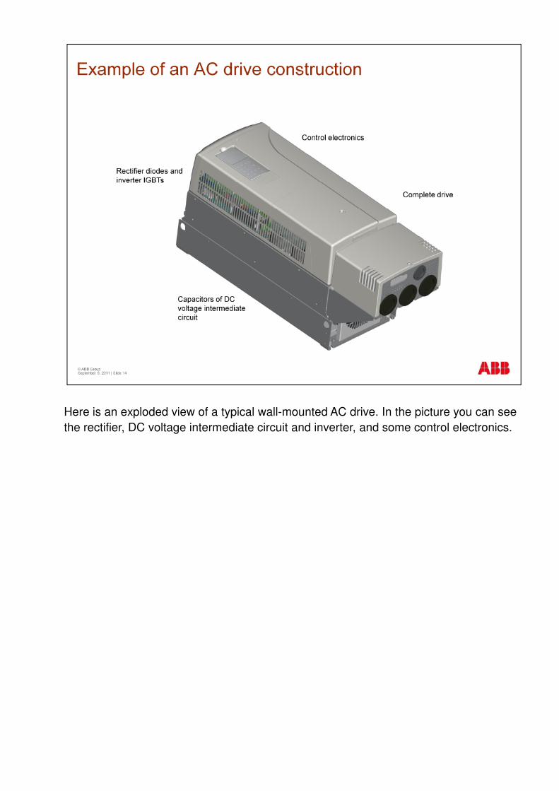
Here is an exploded view of a typical wall-mounted AC drive. In the picture you can see the rectifier, DC voltage intermediate circuit and inverter, and some control electronics.
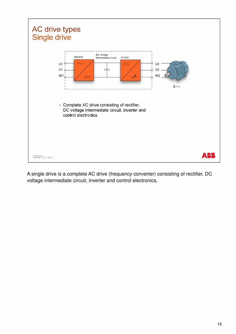
A single drive is a complete AC drive (frequency converter) consisting of rectifier, DC voltage intermediate circuit, inverter and control electronics.
15
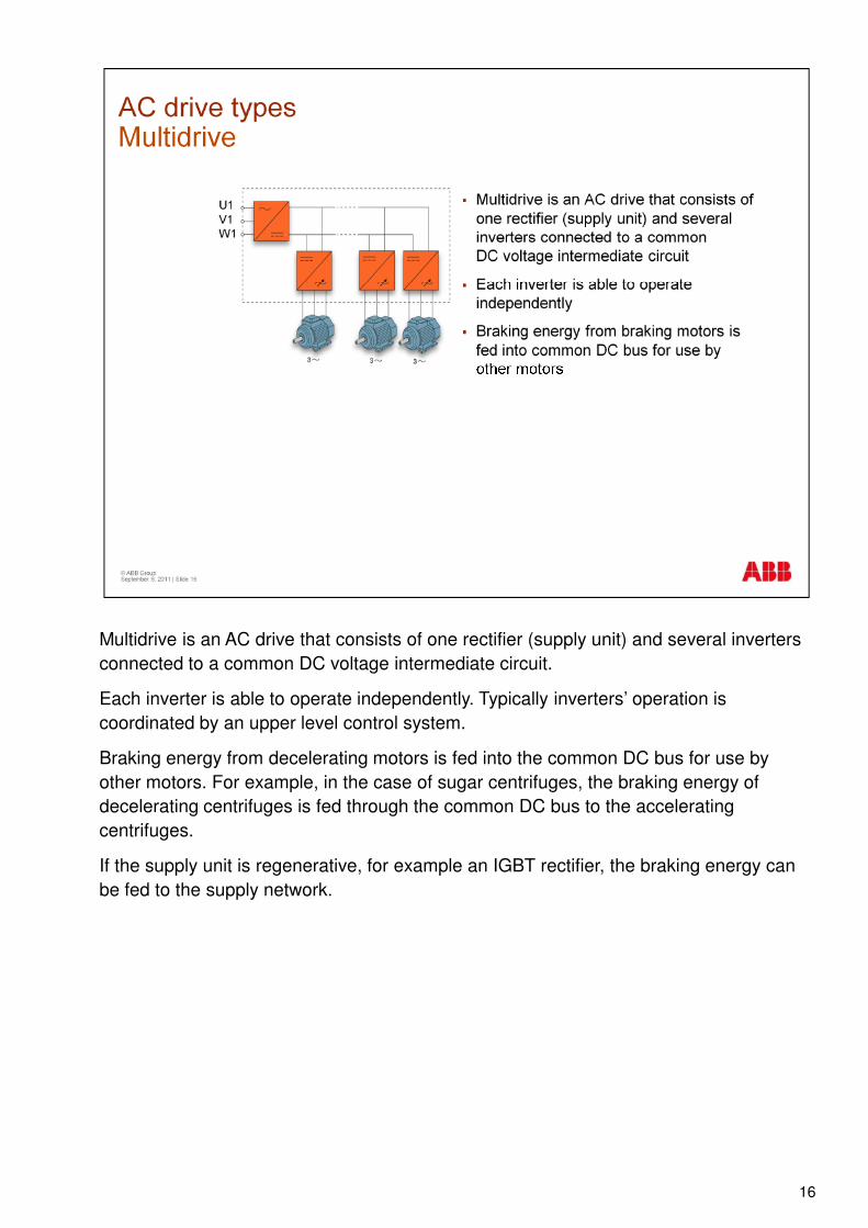
Multidrive is an AC drive that consists of one rectifier (supply unit) and several inverters connected to a common DC voltage intermediate circuit.
Each inverter is able to operate independently. Typically inverters’ operation is coordinated by an upper level control system.
Braking energy from decelerating motors is fed into the common DC bus for use by other motors. For example, in the case of sugar centrifuges, the braking energy of decelerating centrifuges is fed through the common DC bus to the accelerating centrifuges.
If the supply unit is regenerative, for example an IGBT rectifier, the braking energy can be fed to the supply network.
16
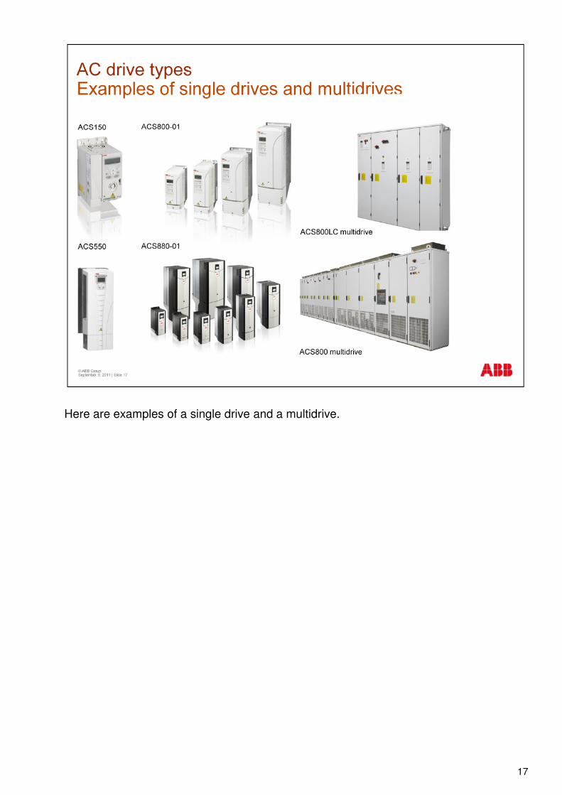
Here are examples of a single drive and a multidrive.
17
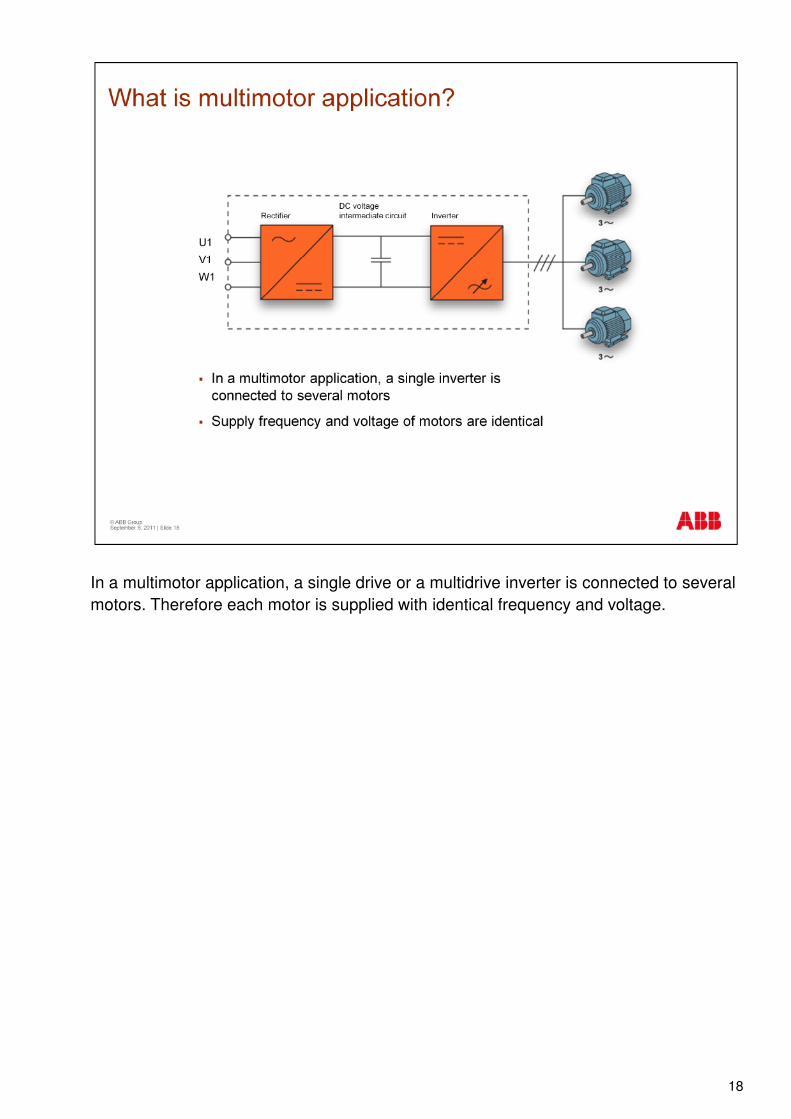
In a multimotor application, a single drive or a multidrive inverter is connected to several motors. Therefore each motor is supplied with identical frequency and voltage.
18
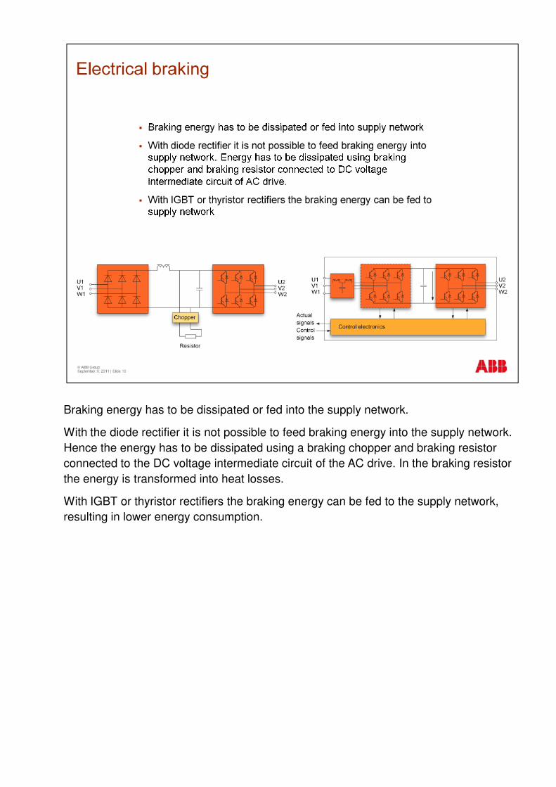
Braking energy has to be dissipated or fed into the supply network.
With the diode rectifier it is not possible to feed braking energy into the supply network. Hence the energy has to be dissipated using a braking chopper and braking resistor connected to the DC voltage intermediate circuit of the AC drive. In the braking resistor the energy is transformed into heat losses.
With IGBT or thyristor rectifiers the braking energy can be fed to the supply network, resulting in lower energy consumption.

Motor operation can be described using four quadrants of a torque-speed coordinate system:
•In the first quadrant the motor is rotating clockwise. Because the motor torque works in the same direction as speed, the drive is accelerating
•In the second quadrant the motor is still rotating clockwise, but the torque works in the opposite direction, so the drive is decelerating
•In the third quadrant the motor is rotating counterclockwise, the torque is working in the •In the third quadrant the motor is rotating counterclockwise, the torque is working in the same direction as speed, therefore the drive is accelerating
•In the fourth quadrant the motor rotation and torque work in different directions, therefore the motor decelerates
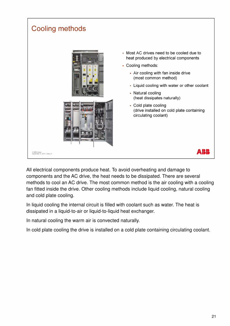
All electrical components produce heat. To avoid overheating and damage to components and the AC drive, the heat needs to be dissipated. There are several methods to cool an AC drive. The most common method is the air cooling with a cooling fan fitted inside the drive. Other cooling methods include liquid cooling, natural cooling and cold plate cooling.
In liquid cooling the internal circuit is filled with coolant such as water. The heat is dissipated in a liquid-to-air or liquid-to-liquid heat exchanger.
In natural cooling the warm air is convected naturally.
In cold plate cooling the drive is installed on a cold plate containing circulating coolant.
21
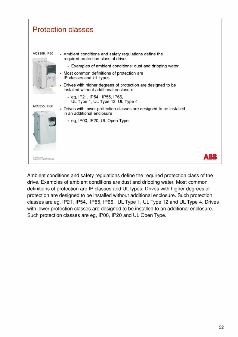
Ambient conditions and safety regulations define the required protection class of the drive. Examples of ambient conditions are dust and dripping water. Most common definitions of protection are IP classes and UL types. Drives with higher degrees of protection are designed to be installed without additional enclosure. Such protection classes are eg, IP21, IP54, IP55, IP66, UL Type 1, UL Type 12 and UL Type 4. Drives with lower protection classes are designed to be installed to an additional enclosure. Such protection classes are eg, IP00, IP20 and UL Open Type.
22
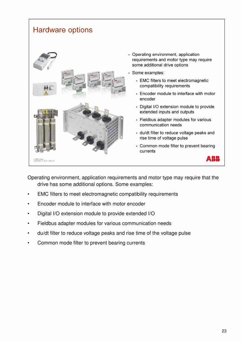
Operating environment, application requirements and motor type may require that the drive has some additional options. Some examples:
• EMC filters to meet electromagnetic compatibility requirements
• Encoder module to interface with motor encoder
• Digital I/O extension module to provide extended I/O
• Fieldbus adapter modules for various communication needs
• du/dt filter to reduce voltage peaks and rise time of the voltage pulse
• Common mode filter to prevent bearing currents
23
So in summary, the main parts of an AC drive are the rectifier, intermediate DC circuit, inverter and control electronics.
A single drive is a complete AC drive (frequency converter).
A multidrive consists of one rectifier and several inverters.
An AC motor can operate in motoring or generating mode, rotating clockwise or counterclockwise. Braking energy can be dissipated in braking resistor or fed to the supply network.supply network.
The ambient conditions and safety regulations define the required protection class of the drive.
24

Thank you for your attention. You may now go ahead and move on to the next e-learning module.
25