Embed Size (px)
Citation preview
PIPER AIRCRAFT CORPORATIONPA-28RT-2OIT, TURBO ARROW IV
SECTION 7DESCRIPTION /OPERATION
SECTION 7
DESCRIPTION AND OPERATIONOF THf, AIRPLANE AND ITS SYTEMS
7.I THE AIRPLANE
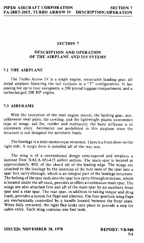
The Turbo Arrow IV is a single engine, retractable landing gear, allmetal airplane featuring the tail surfaces in a "T" configuration. It hasseating for up to four occupants, a 200 pound luggage compartment, and aturbocharged 200 HP engine.
7.3 AIRFRAME
With the exception of the steel engine mount, the landing gear, mis-cellaneous steel parts, the cowling, and the l ightweight plastic extremities{tips of wings, tail f in, rudder and stabilator), the basic airframe is ofaluminum alloy. Aerobatics are prohibited in this airplane since thestructure is not designed for aerobatic ioads.
The fuselage is a semi-monocoque structure. There is a front door on theright side. A cargo door is installed aft of the rear seat.
The wing is of a conventional design semi-tapered and employs alaminar flow NACA 652415 airfoil section. The main spar is located atapproximately 4070 of the chord aft of the leading edge. The wings areattached to the fuselage by the insertion of the butt ends of the spar into aspar box carry-through, which is an integral part of the fuselage structure.The bolting ofthe spar ends into the spar box carry-through structure, whichis located under the aft seats, provides in effect a continuous main spar. Thewings are also attached fore and aft of the main spar by an auxiliary frontspar and a rear spar. The rear spar, in addition to taking torque and dragloads, provides a mount for flaps and ailerons. The four-position wing flapsare mechanically controlled by a handle located between the front seats.When fully retracted, the right flap locks into place to provide a step forcabin entry. Each wing contains one fuel tank.
REPORT: VB-9407-l
ISSUED: NOVEMBER 30. 1978
SECTION 7DESCRIPTTON/OPERATION
PIPER AIRCRAFT CORPORATIONPA-28RT-2OIT, TURBO ARROW IV
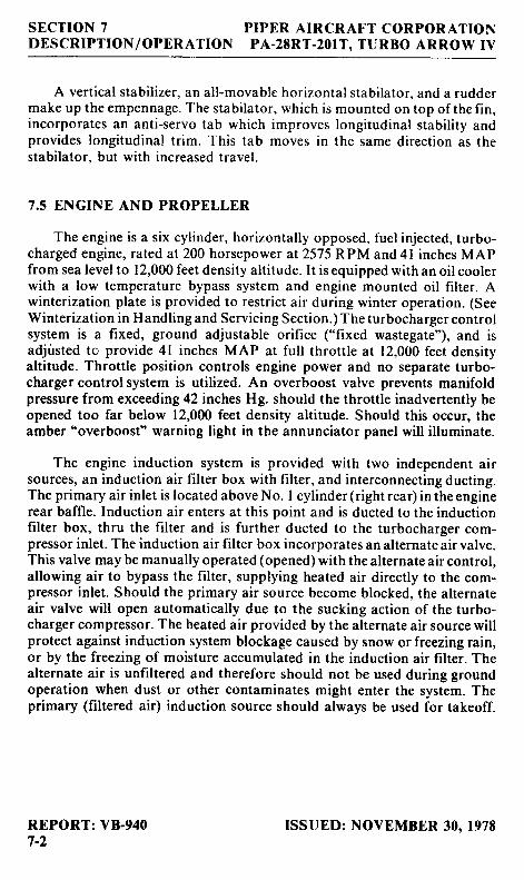
A vertical stabil izer, an all-movable horizontal stabilator, and a ruddermake up the empennage. The stabilator, which is mounted on top of the fin,incorporates an anti-servo tab which improves longitudinal stabil ity andprovides longitudinal trim. This tab moves in the same direction as thestabilator, but with increased travel.
7.5 ENGINE AND PROPELLER
The engine is a six cylinder, horizontally opposed, fuel injected, turbo-charged engine, rated at 200 horsepower at 2575 RPM and 4l inches MAPfrom sea level to 12,000 feet density altitude. It is equipped with an oil coolerwith a low temperature bypass system and engine mounted oil filter. Awinterization plate is provided to restrict air during winter operation. (SeeWinterization in Handling and Servicing Section.) The turbocharger controlsystem is a fixed, ground adjustable orifice ("fixed wastegate"), and isadjüsted to provide 4l inches MAP at full throttle at 12,000 feet densityaltitude. Throttle position controls engine power and no separate turbo-charger control system is utilized. An overboost valve prevents manifoldpressure from exceeding 42 inches Hg. should the throttle inadvertently beopened too far below 12,000 feet density altitude. Should this occur, theamber'overboost" warning light in the annunciator panel will illuminate.
The engine induction system is provided with two independent airsources, an induction air filter box with filter, and interconnecting ducting.The primary air inlet is located above No. I cylinder (right rear) in the enginerear baffle. Induction air enters at this point and is ducted to the inductionfilter box, thru the filter and is further ducted to the turbocharger com-pressor inlet. The induction air filter box incorporates an alternate air valve.This valve may be manually operated (opened) with the alternate air control,allowing air to bypass the filter, supplying heated air directly to the com-pressor inlet. Should the primary air source become blocked, the alternateair valve will open automatically due to the sucking action of the turbo-charger compressor. The heated air provided by the alternate air source willprotect against induction system blockage caused by snow or freezing rain,or by the freezing of moisture accumulated in the induction air filter. Thealternate air is unfiltered and therefore should not be used during groundoperation when dust or other contaminates might enter the system. Theprimary (filtered air) induction source should always be used for takeoff.
REPORT: VB-9407-2
ISSUED: NOVEMBER 30. 1978
PIPER AIRCRAFT CORPORATIONPA-28RT-2OIT. TURBO ARROW IV
SECTION 7DES CRIPTION / OPERATION
A RayJay turbocharger on the engine is operated by the engine exhaust
gases. The exhaust gases drive a turbine wheel which is coaxial with a com-
p..tto. wheel. Induction air entering the compressor wheel,is compressed
änd delivered to the engine induction distribution system and hence to each
cylinder. The amount of induction air compression is a function of engine
power - low power, low compression; high power, higher compression' Any
äxcessive prössure (and flow) is expelled by the overboost valve discussedpreviously.
The fuel injection system incorporates a metering system whichmeasures the rate at which turbocharged air is being used by the engine and
dispenses fuel to the cylinders proportionally. Fuel is supplied to the injectorpump at a greater rate than the engine requires. The fuel injection system is a
"continuous flow" tYPe.
A combination fuel flow indicator and manifold pressure gauge is
installed in the left side of the instrument panel. The fuel flow indicator is
connected to the fuel flow divider and monitors fuel pressure. The instru-
ment converts fuel pressure to an approximate indication of fuel flow in
gallons per hour and percentage of cruise power.
To obtain maximum efficiency and time from the engine, follow theprocedures recommended in the Teledyne continental operator's Manualprovided with the airplane.
The Hartzell constant speed propeller is controlled by a governor
mounted on the left forward side of the crankcase. The governor is con-
trolled by a cable from the power control quadrant. A choice of a two bladed(standard) propeller or a three bladed (optional) propeller is offered.
REPORT: VB-9407-3
ISSUED: NOVEMBER 30. 19?t
SECTION 7DESCRIPTION /OPERATION
PIPER AIRCRAFT CORPORATIONPA-2tRT.2OIT, TURBO ARROW IV
::t
{
REPORT: YB.9{071
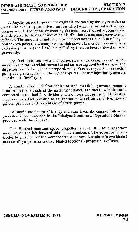
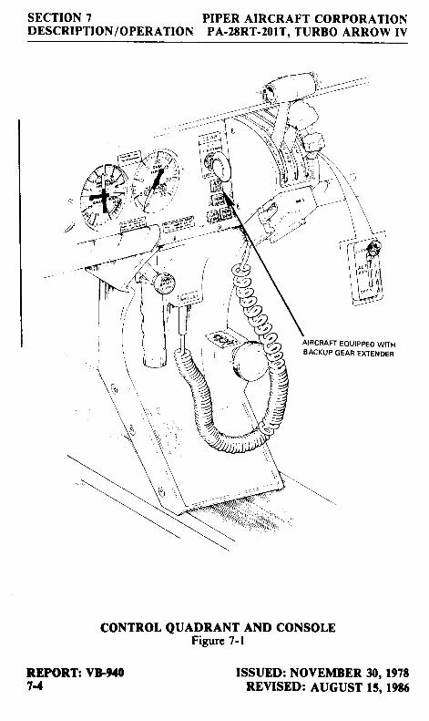
CoNTROL QUADRANT AND CONSOLEFigure 7-l
AIRCRAFT EOUIPPED WITHBACKUP GEAR EXTENDER
ISSUED: NOVEMBER 30, l97tREYISED: AUGUST 15, tgtd
PIPER AIRCRAFT CORPORATIONPA.28RT.2O1T, TURBO ARROW IV
SECTION 7DESCRIPTION /OPERATION
7.7 ENGINE CONTROLS
F-ngine controls consist of a throttle control. a propeller control and amixture controi le ver,
' fhese controls are located on the control quadrant on
the lower center of the inst rument panel (F igure 7- l ) where they areaccessib l r ta boi f r t l re p i lo t and the copi lo t . The contro ls ut i l ize tef lon- l inedcontro i cables tc rec luce f r ic t ion and b inding.
l he throttle levrl i i ; used tci adjust the manifold pressure. lt incorporatesa gear up *,arning horri srvitch which is activated during the last portion oft ravel o i the throt r le lev i i - to the low power posi t ior r . I f the landing gear is lnot io iked dc-rwr: . t l ' ,e hcrn wi l l sor , rnd unt i l the gear is down arrd locked or lunt i l the pou,er setr ing is increased. This is a säfet l , feature tc warn of anli r r adve r ten l Fea r u [ ' l and rnp
"i ' lre propeller control leve; is used to adjust the propeller srreed fiornh igh RPha to i ow RPM.
T'he nrixture control lever is used to adiust the air tc fuel ratio. Theengine rs sliut down by the placing of the mixture control lever in the full leanposition. In addition, the mixture controi has a lock to prevent activation ofttre rnixture control insteaC of the pitch control. For information on theleaning procedure. see the Continental Operator's Manual.
The friction adjustment lever on the right side of the control quadrantmay be adjusted to increase or decrease the friction holding the throttle,propeller. and mixture controls in a selected position. I
The alternate air control is located to the right of the control quadrant.When the alternate air lever is in the up, or closed, position the engine isoperating on fi l tered air; when the lever is in the down, or open, position theengine is operating on unfi ltered, heated air (refer to Figure 7-l).
ISSUED: NOVEMBER 30, 197tREVISED: FEBRUARY 6, 1979
REPORT: VB-9407_5
SECTION 7DESCRIPTION / OPERATION
PIPER AIRCRAFT CORPORATIONPA.28RT.2OIT. TURBO ARROW IV
lo Rp[ 25
AIRCRAFT EOUIPPED WITHBACKUP GEAR EXTENDER
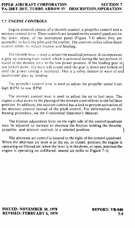
LANDING GEAR SELECTORFigure 7-3
7.9 LANDING GEAR
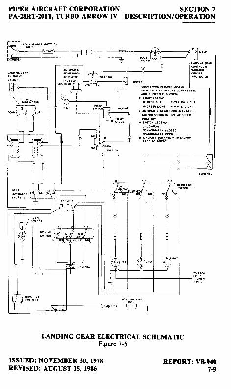
The Turbo Arrow IV is equipped with a retractable tricycle landing gear,which is hydraulically actuated by an electrically powered reversible pump.The pump is controlled by a selector switch on the instrument panel to theleft of the control quadrant (Figure 7-3). The landing gear is retracted orextended in about seven seconds.
Some aircraft also incorporate a pressure sensing device in the systemwhich lowers the gear regardless of gear selector position, depending uponairspeed and engine power (propeller slipstream). Gear extension is designedto occur, even if the selector is in the up position, at airspeeds belowapproximately 103 KIAS with power off.The extension speeds will varyfr-om approximately 78 KTS to approximately 103 KIAS depending onpower settingS and altitude. The device also prevents the gear from retractingät airspeeds below approximately 78 KTS with full power, though theselectoi switch may be in the up position. This speed increases with reduced
REPORT: VF9401-6
ISSUED: NOVEMBERREVISED: AUGUST
30, l97t15, 19t6
PIPER AIRCRAFT CORPORATIONPA-2tRT-201T, TURBO ARROW IV
SECTION 7DESCRIPTION / OPERATION
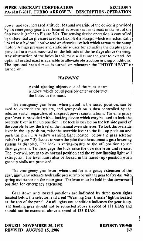
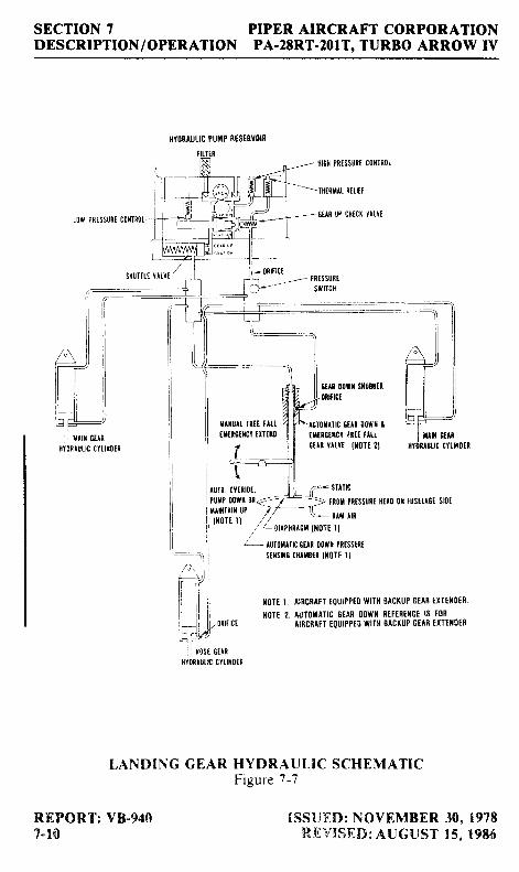
power and/or increased altitude. Manual override of the device is providedby an emergency gear lever located between the front seats to the left oftheflap handle (refer to Figure 7-9). The sensing device operation is controlledby differential air pressure across a flexible diaphragm which is mechanicallylinked to a hydraulic valve and an electrical switch which actuates the pumpmotor. A high pressure and static air source for actuating the diaphragm isprovided in a mast mounted on the left side of the fuselage above the wing.Any obstruction of the holes in this mast wil l cause the gear to extend. Anoptional heated mast is available to alleviate obstruction in icing conditions.The optional heated mast is turned on whenever the "PITOT HEAT" isturned on.
IYARNING
Avoid ejecting objects out of the pilot stormwindow which could possibly ent€r or obstructthe holes in the mast.
The emergency gear lever, when placed in the raised position, can beused to override the system, and gear position is then controlled by theselector switch regardless of airspeed/power combinations. The emergencygear lever is provided with a locking device which may be used to lock theoverride lever in the up position. The lock is located on the left side panel ofthe console below the level of the manual override lever. To lock the overridelever in the up position, raise the override lever to the full up position andpush the pin in. A yellow warning light located below the gear selectorswitch (Figure 7-3) flashes to warn the pilot that the automatic gear loweringsystem is disabled. The lock is spring-loaded to the off position to aiddisengagement. To disengage the lock raise the override lever and release.The lever will return to its normal position and the yellow flashing light willextinguish. The lever must also be locked in the raised (up) position whengear-up stalls are practiced.
The emergency gear lever, when used for emergency extension of thegear, manually releases hydraulic pressure to permit the gear to free-fall withspring assistance on the nose gear. The lever must be held in the downwardposition for emergency extension.
Gear down and locked positions are indicated by three green lightslocated below the selector, and a red "Warning Gear Unsafe'light is locatedat the top of the panel. An all lights out condition indicates the gear is up.The landing gear should not be retracted above a speed of I I I KIAS andshould not be extended above a speed of 133 KIAS.
ISSUED: NOVEMBER 30, 197tREVISED: AUGUST 15, l9t6
REPORT: VB94l)7-7
SECTION 7DESCRIPTION/ OPERATION
PIPER AIRCRAFT CORPORATIONPA.2tRT.2OIT. TURBO ARROW IV
The main landing gear uses 6.00 x 6 wheels. The main gear incorporatebrake drums and Cle veland single disc hydraulic brake assemblies. The nosewheel carries a 5.00 x 5 four ply tire and the main gear use 6'00 x 6 six ply
tires. All three tires are tube type.
A micro-switch in the throttle quadrant activates a warning horn andred "Warning Gear Unsafe" l ight under the following conditions:
(a) Gear up and power reduced below approximately 14 inches ofmanifold pressure.
(b) On aircraft equipped with the backup gear extender, if the systemhas extended the landing gear and the gear selector is UP, with thereduced below approximately l4 inches of manifold pressure.
(c) Gear selector switch "UP" while on the ground and throttle inretarded position.
On aircraft which are NOT equipped with the backup gear extender anadditional switch is installed which activates the warning horn and lightwhenever the flaps are extended beyond the approach position ( l0o) and the
landing gear are not down and locked.
The gear warning horn emits a 90 cycle per minute beeping sound incontrast to the stall warning horn which emits a continuous sound.
The nose gear is steerable through a 30 degree arc each side of centerthrough the use of the rudder pedals. As the nose wheel retracts, the steeringlinkage disengages to reduce rudder pedal loads in flight. The nose wheel is
equipped with a hydraulic shimmy dampener to reduce nose wheel shimmy'
Abungee assembly is also included to reduce ground steering effort and to
dampen shocks and bumps during taxiing.
The oleo struts are of the air-oil type, with normal extension being 2.75 t
.25 inches for the nose gear and 2.5 t .25 inches for the main gear under
normal static load (empty weight of airplane plus full fuel and oil).
The standard brake system includes toe brakes on the left and right set of
rudder pedals and a hand brake located below and near the center of the
instrum-ent panel. The toe brakes and the hand brake have individual brake
cylinders, but all cylinders use a common reservoir. The parking brake is
incorporated in the lever brake and is operated by pull ing bat on the lever
and depressing the knob attached to the top of the handle. To release theparking brake, pull back on the brake lever; then allow the handle to swingforward.
REPORT: VF9407-t
ISSUED: NOVEMBER 30' l97tREVISED: AUGUST 15, l9t6
PIPER AIRCRAFT CORPORATIONPA.2tRT.2IIIT, TURBO ARROW IV
SECTION 7DESCRIPTION/OPERATTON
j ***- I ot 1;p;.t;"'ot,^ott
o'
LAMI iG G€AFACTUATOF
r -....11Y.9,
roo n
TU^ lOn)TE ! )5 ) P S
l t l t-T
I
r GEAn SHOWT ril @Wt L6XEO
rcsrrroi wrTH stRut5 cogPREssE0ANO TAFOTILC GLOSTD.
? I IGHT LEGEilO:ß . R E O L I G A I Y . Y E L L d L T H T
G.GREf i L IGXT I . |H IE L IGNT
!. AU'SAtTC GEln OO*i ACTUATOR
swr tcH sNof t r t Lo* l rRsPEEoP0sr I ro i .
. . SWITCH L€GEND:
c- co f l loxXC-XOFIALLY CLOSEONO-rcRIALLY OPEN
5 AIRCFAF] EOUIPPEO WIIH UCXUP6Ern EXTE[O€i .
i ' O U PI crcrt
SWtTCH
rkRotT !E
ISSUED: NOVEMBER 30, l97tREWSED: AUGUST 15, l9t6
owil LocxsttTcx
REPORT: V&9{07-9
LANDING GEAR ELECTRTCAL SCHEMATICFigure 7-5
SECTION 7DESCRIPTION /OPERATION
PIPER AIRCRAFT CORPORATIONPA.28RT.2OIT, TURBO ARROW IV
llYORAULIC PUiIP RISERVOIR
PUIP 00wl{ 0r<- 7 * ..:>>
rnor pRtss|Jrt |i[l0 0t r|Jsfl.lßt stDtxlHTlil IJP r/- 11.äoi i rL /
\ : f , r r^n'
/ L | ) r rPNnrGt I IoTE l l
L0w Pnrss|JRt c0flTRoL-
Iilft Gtanfir0nAuuN ctui|)tn
6t^t 00rr lilJ$tr0ilfiGt
tltu^t Ittt ttu,IXn0fltct trTt|(0
LANDING GEAR
Rf,PORT: VB-940?-10
L 1919v1116 g11x ttof,tt Pttssünts$slr€ cllrrrrn l l0lt t l
II{ITT I, AIRCRATT EOUIPPTO WITH BACKUP GTAß EXTEIIl lES'
xoTE 2. luT0tlATlc 0€AR 00wll 8€Ftßtl{ct ls toRAIiCBA'I EOUIPPEO WITH EACKUP GIAß TXTTIII)EI
HYDRAUI,TC SCHEMATICFisure 7-7
ruTotl]tc 6tA[ 00[|l tIrItGttct fßtt fll.LGrAt y^r.Yr. {t0TE 2}
ttxt 6iltcil.trotn
ISS{JED: NOVEIltBf,R 30, 1978REV{SED: AUGIJST 15. 1986
Il t I0 0vtnl|)t,
PIPER AIRCRAFT CORPORATIONPA-2ERT-2O1T. TT]RBO ARROW IV
SECTION 7DESCRIPTION /OPERATION
IIJ
AIRCRAFT EOUIPPED WITHEACKUP GEAR EXTENDER
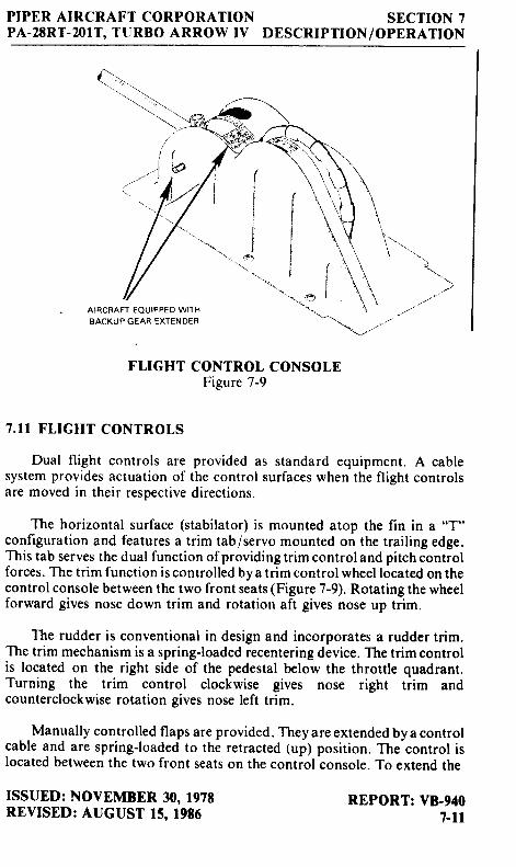
FLIGHT CONTROL CONSOLEFigure 7-9
7. I I FLIGHT CONTROLS
Dual f l ight controls are provided as standard equipment. A cablesystem provides actuation of the control surfaces when the flight controlsare moved in their respective directions.
The horizontal surface (stabilator) is mounted atop the fin in a "T"configuration and features a trim tab/servo mounted on the trailing edge.This tab serves the dual function ofproviding trim control and pitch controlforces, The trim function is controlled by a trim control wheel located on thecontrol console between the two front seats (Figure 7-9). Rotating the wheelforward gives nose down trim and rotation aft gives nose up trim.
The rudder is conventional in design and incorporates a rudder trim.The trim mechanism is a spring-loaded recentering device. The trim controlis located on the right side of the pedestal below the throttle quadrant.Turning the trim control clockwise gives nose right trim andcounterclockwise rotation gives nose left trim.
Manually controlled flaps are provided. They are extended by a controlcable and are spring-loaded to the retracted (up) position. The control islocated between the two front seats on the control console. To extend th€
\
ISSUED: NOVEMBER 30, 1978REVISED: AUGUST 15. l9t6
REPORT: VF9407-ll
SECTION 7DESCRIPTION /OPERATION
PIPER AIRCRAFT CORPORATIONPA-28RT-201T, TURBO ARROW IV
flaps pull the handle up to the desired flap setting of 10, 25 or 40 degrees. Toretract, depress the button on the end of the handle and lower the control.
When extending or retracting flaps, there is a pitch change in the air-craft. This pitch change can be corrected either by stabilator trim orincreased control wheel force. When the flaps are in the retracted positionthe right flap, provided with a over-center lock mechanism, acts as a step'
NOTE
The right flap will support a load only in thefully retracted (up) position. When loading andunloading passengers make sure the flaps are inthe retracted (uP) Position.
7.T3 FUEL SYSTEM
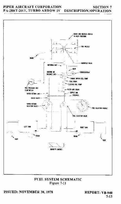
The fuel system was designed with simplicity in mind. lt incorporatestwo fuel tanks, one in each wing containing 38.5 U.S' Gallons, giving a total
; capacity of 77 gallons, of which 72 gallons are usable. Each tank is equippedI with a fil ler neck indicator tab to aid in deterrnining fuel remaining when theI tanks are not full. Usable capacity to the bottom of the indicator tab is 25I gallons. The minimum fuel grade is i00 or l00LL Aviation Grade. The tanksare attached to the leading edge of the wing with screws and are an integralpart of the wing structure. This allows removal for service. The tanks arevented individually by a vent tube which protrudes below the bottom of thewing at the rear inboard corner of each tank. The vents should be checkedperiodically to ascertain that the vent is not obstructed and will allow freepassage of air.
Each fuel tank has an individual quick drain located at the bottominboard rear corner. The fuel strainer also incorporates a quick drain, whichis located on the left lower portion of the firewall. The quick drain protrudetthru the cowling to allow easy draining of the fuel strainer. To avoid theaccumulation of water and sediment, the fuel tank sumps and strainershould be drained daily prior to first flight and after refueling.
CAUTION
When draining fuel, care should be taken toensure that no fire hazard exists before startingthe engine.
REPORT: V&94O7-t2
ISSUED: NOVEMBER 30, l97tREVISED: AUGUST 22, l9t0
PIPER A IRCRAFT CORPORATIONPA-28RT-2OIT, TURBO ARROW IV
SECTION 7DESCRIPTION /OPER ATION
-t
- !
ülü' . /
Yrfin nm,ni isfl-rcr0R Yil.Yr ---i-,
j\ ''r I
üillfitn GAUGIS
FUEL SYSTEM SCHEMATICFigure 7-l I
ISSUED: NOVEMBER 30, 1978 REPORT: VB-9407-13
SECTION 7DESCRIPTION /OPERATION
PIPER AIRCRAFT CORPORATIONPA-2ERT-2OIT, TURBO ARROW IV
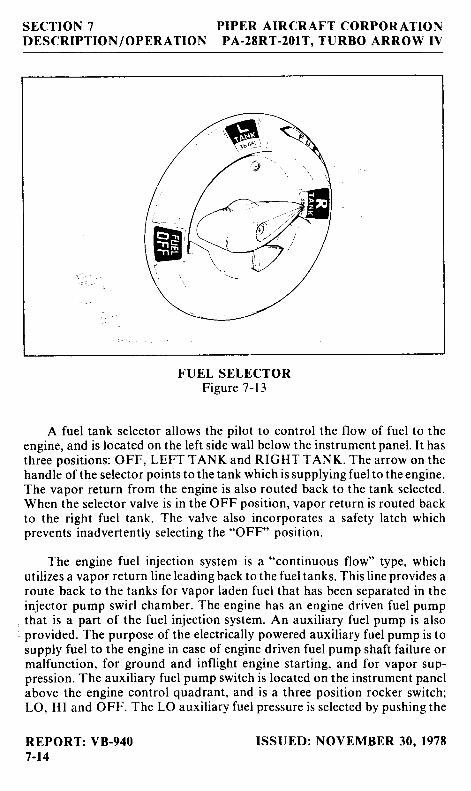
FUEL SELECTORFigure 7-13
A fuel tank selector allows the pilot to control the flow of fuel to theengine, and is located on the left side wall below the instrument panel. It hasthree positions: OFF, LEFT TANK and RIGHT TANK. The arrow on thehandle of the selector points to the tank which is supplying fuel to the engine.The vapor return from the engine is also routed back to the tank selected.When the selector valve is in the OFF position, vapor return is routed backto the right fuel tank. The valve also incorporates a safety latch whichprevents inadvertently selecting the "OFF" position.
The engine fuel injection system is a "continuous flow" type, whichutil izes a vapor return l ine leading back to the fuel tanks. This l ine provides aroute back to the tanks for vapor laden fuel that has been separated in theinjector pump swirl chamber. The engine has an engine driven fuel pumpthat is a part of the fuel injection system. An auxil iary fuel pump is alsoprovided. The purpose of the electrically powered auxiliary fuel pump is tosupply fuel to the engine in case of engine driven fuel pump shaft failure ormalfunction, for ground and inflight engine starting, and for vapor sup-pression. The auxiliary fuel pump switch is located on the instrument panelabove the engine control quadrant, and is a three position rocker switch;LO, HI and OFF. The LO auxil iary fuel pressure is selected by pushing the
REPORT: VB-9407-t4
ISSUED: NOVEMBER 30. l97E
PIPER A IRCRAFT CORPORATIONPA.28RT-2OIT , TT IRBO ARROW IV
SECTION 7DESCRIPT ION/OPER AT ION
1-he engine fuel in ject ion system is a "cont inuous f low" type. whichut i l izes a vapor return l ine leading back to the fuel tanks. This l ine prov ides aroute back to the tanks for vapor laden fuel that has been separated in thein jector pump swir l chamber. The engine has an engine dr iven fuel pumpthat is a par t of the fuel in ject ion system. An auxi l iary fuel pump is a lsoprovided. The purpose of the e lect r ica l ly powered auxi l iary fuel pump is tosupply fuel to the engine in case of engine dr iven fuel pump shaf t fa i ture ormal funct ion, for ground and inf l ight engine star t ing, and for vapor sup-pression. ' l 'he auxi l iary fuel pump swi tch is located on the inst rument panelabove the engine contro l quadrant , and is a three posi t ion rocker swi tch,l -O, HI and OFF. The l -O auxi l iary fuel pressure is se lected by pushing thetop of the swi tch. The Hl auxi l iary fuel pressure is se lected by, pushing rhebot tom of the swi tch, but th is can be done only a l ter unlatching the adjacenrguard. W hen the H I au x i l iarv fuel pump is act ivated. an amber i ight near theannunc ia t i on pane l i s i l l um ina ted . Th i s l i gh t d ims wheneve r t he pumppressurc reduces autonrat ica l ly and mani fo ld pressure is below approxi -mately 2 l inches.
ln casc of a la i led engine dr iven fuel pump, the auxi l iary e lect r ic fuelpump should be set on H l . Adequate pressure and l 'ue l f low wi l l be suppl iedfor up 1o approximately 75a7i1 power. Manual leaning to the correct fuel f lowwi l l be requi red at a l t i tudes above 15,000 leet and for engine spe eds less than2300 RPM. An absolute pressure swi tch automat ica l ly se lects a lower fuelpressure when the throt t le is reduccd below ) l " Hg mani fo ld pressure andthe HI auxi l iarv fuel pump is on.
N O T E
Excessive fuel pressure and very r ich fuel /a i rmixtures wi l l occur i f the Hl posi t ion is ener-g ized when the engine fuel in ject ion system isfunct ioning normal ly .
Low auxi l iary fuel pressure is avai lable and may be used dur ing normalengine operat ion both on the ground and inf l ight for vapor suppresslonshould it be necessary as evidenced by unstable engine operation orfluctuating fuel f low indications during idle or at high altitudes.
A spr ing loaded OFF pr imer but ton swi tch is located on the inst rumentpanel and is used to select HI auxi l iary fuel pump operat ion for pr iming,irrespective of other switch positions. The primer button may be used forboth hot or cold engine starts.
ISSUED: NOVEMBER 30, 1978REVISED: AUGUST 8 . 1983
REPORT: VB-9407-15
SECTION 7DESCRIPTION /OPERATION
PIPER A IRCRAFT CORPORATIONPA-28RT.2OIT, TT]RBO ARROW IV
On ai rp lanes equipped wi th an opt ional engine pr imer system ( ident i f iedby Placard below pr imer but ton shown in F igure 7-2 l1, the pr imer swi tchlocat ion and actuat ion is the same as the basic a i rp lane. However, th issystem does provide a separate pr imer system as an in tegra l par t of thecngine fuel system. An e lect r ica l ly operated d iver ter va lve is located in themetered fuel supply l ine between the a i r throt t le valve and the mani fo ldvalve. Other components are two pr imer nozzles, located in the in takemani l 'o ld on each s ide of the engine, the in terconnect ing fuel l ines, and f inewire spark p lugs. Actuat ion of the engine pr imer swi tch operates theauxi l iary e lect r ic fuel pump on Hl and energiz .es the d iver ter va lve whichsuppl ies fuel to each pr imer nozzle.
' fhe d iver ter va lve does not shut of f a l l
fue l f low to the mani fo ld valve. therefore some quant i ty of fuel is a lsosuppl ied to each cy l inder nozzle dur ing pr iming. Operat ion of the auxi l iarvfuel pump on Hl and LO is unchanged.
7 . I 5 ELECTRICAL SYSTEM
Al l swi tches are grouped in a swi tch panel above the power quadrant .On the lower r ight s ide of the inst rument panel is the c i rcu i t breaker panel ,wi th each breaker c lear ly marked to show what c i rcu i t i t protects. Also,c i rcu i t prov is ions are made to handle the addi t ion of communicat ions andnavigat ional equipment .
Standard e lect r ica l accessor ies inc lude a l ternator , s tar ter , e lect r ic fuelpump, s ta l l warning indicator . ammeter , and annunciator panel .
The annunciator panel inc ludes a l ternator and low oi l pressure indicatorl ights. When the opt ional gyro system is insta l led. the annunciator panel a lsoinc ludes a low vacuum indicator l ight . The annunciator panel l ights arcprovided only as a warning to the p i lo t that a system may not be operat ingproper ly , and that he should check and moni tor the appl icable system gaugeto determine when or i f any necessary act ion is requi red.
Opt ional e lect r ica l accessor ies inc ludes navigat ion, ground recogni t ion,ant i -co l l is ion. landing, inst rument and cabin dome l ights. Navigat ion andradio l ights are contro l led by a rheostat swi tch on the le f t s ide of the swi tchpanel . The inst rument panel l ights are contro l led by a rheostat swi tch on ther i gh t s i de o f t he panc l .
REPORT: V8-9407-16
ISS t l f ,D : NOVEMBER 30 . 1978REVISED: JULY 16 . l 9E4
PI I 'F ,R AIR( ]RAFT C]ORPORATIONPA-28RT' -201T, t {JRBO ÄRROW IV
SECTION 7D [SCRI P] ' ION / OPE,R ATIO N
An op t i ona l l i gh t , moun tcd i n t hc ovc r l r ca i l panc [ . p rov idcs i t r s t ru t t t cn tand cockpi t l ight ing f .or n ight f ly ing.
- l l rc l ight is contro l lcd hy a rhcostat
swi tch locatcd ac l . jaccnt to thc l ight . A rnap l ight window in the lcns isactu i r tcd by an ac l . iaccnt swi lch.
An opt ional wing t ip l rccogrr i t ion l ight system consists of 2 I ights (onc incn t :h w ing t i p ) and i s ope ra t cd by a sp l i t l and ing l i gh t / r ecogn i t i on l i gh ti 'ockcr typc swi tc l r r r . rorrntc<l on t l tc swi tch pancl .
I I / A R N I N G
Wl rcn op t i ona l p : rnc l l i gh t s a rc i r r s ta l l cd ,rhe ostat srv i tch nrr rs t bc o i f to obta in gcar l ightsfu l l i n tens i t y du r i ug day t imc f l y i ng . Whenaircraf ' t is < lperatcd at n ight zrnd panel l ightrheostat swi tch is turned on, gear l ights andovc r boos l l i gh t w i l l au ton la t i ca l l y < l i l r r .
C'A L]7-IO N
I)o not usc c igar l ighter rcccptac les as p() \ . \ /crsou rccs f o r an l , dev i ccs o thc r t han t l r c c i ga rl i gh t c r s supp l i cd r v i t h t l r c a i rp lane . A r t v o t l r c rr lcv ice p luggcr l in to thcsc rcce ptac lcs r r tay bcd a ntageil .
ISS t I I i I ) : A t l ( ; t JS ' l ' 8 . 1983RI iVISl , l l ) : SI iP ' i l iMßl tR 30, 1985
RIr l 'OR' l ' : Vß-9407 -l6a
PIPER A IRCRAFT CORPORATIONPA-28RT.2OIT , TURBO ARROW IV
SECTION 7DESCRIPTION/OPERATION
. . i I
I vo.reor _
o-vtav
I FEcUL^ron coN
ai
. r A L T E i X A i O i
f I E L O 5 A H P
I
a r N ! N c r a t o n
- . - ' - - . ' _ - ' 1 9
u c x r s : r u eL--t---?-
A I ' E R N A T O Rs r J r c H
.<j r+=,_.+_t1
iii. i.=u
a
t---T*---- _l
S E N S
iI
omöu.
I
- l
il i :
R€C' PTACLE
f li :r.li 1I riiI l1 c ro rn
J l l L '0 HrEF
I Y
I
r r|lc !l!l!l!
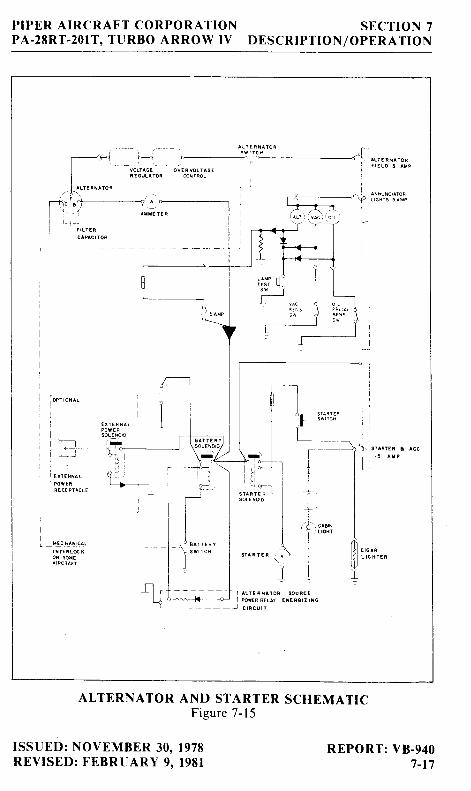
ALTERNATOR AND STARTER SCHEMATICFigure 7-15
ISSUED: NOVEMBER 30, 1978REVISED: FEBRUARY 9 . l98 l
REPORT: V8-9407_17
SECTION 7 PIPER AIRCRAFT CORPORATIONDESCRIPTION/OpERATION pA-28RT-201T, TURBO ARROW IV
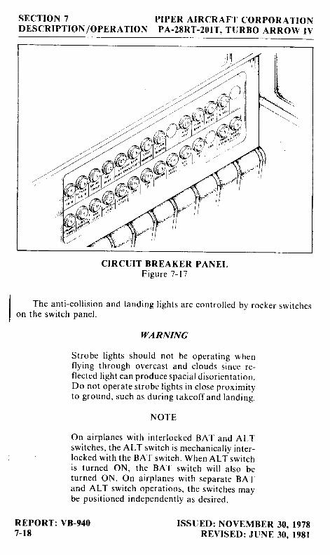
CIRCUIT BREAKER PANELFigure 7-17
The anti-coll ision and landing l ights are controlled by rocker switcheson the switch panel.
WARNING
Strobe l ights should not be operat ing whenflying through overcast and clouds since re-flected l ight can produce spacial disorientation.Do not operate strobe lights in close proximitvto ground, such as during takeoff and landing.
NOTE
On ai rp lanes wi th in ter locked BAT and ALTswitches, the ALT switch is mechanically inter-locked with the BAT switch. When ALT switchis turned ON, the BAT switch wil l also beturned ON. On airplanes with separate BATand ALT switch operations, the switches maybe positioned independently as desired.
REPORT: VB-940 ISSUED: NOVEMBER 30, l97B7-18 REVISED: JUNE 30, l98l
PIPER A IRCRAFT CORPORATIONPA.28RT-2OIT , TT ]RBO ARROW IV
SECTION 7DESCRIPT ION /OPERATION
The pr imary e lect r ica l power source is a l4-vol t , 65-amp al ternator ,which is protected by a vol tage regulator and an overvol tage re lay. Theal ternator prov ides fu l l e lect r ica l power output even at low engine RPM.This prov ides improved radio and e lect r ica l equipment operat ion andincreases bat tery l i fe by reducing bat tery load.
Secondary power is prov ided by a I2-vol t , 25-ampere hour batrery.
The ammeter as insta l led does not show bat tery d ischarge; rather i tshows the e lect r ica l load p laced on the system. With a l l the e lect r ica l equip-ment of f , and the master swi tch on, the ammeter wi l l ind icate the chargingrate of the bat tery. As each e lect r ica l uni t is swi tched on, the amme ter wi l lind icate the tota l ampere draw of a l l the uni ts inc luding the bat tery. Forexample, the average cont inuous load for n ight I ' ly ing wi th radios on is about30 amperes. The 30 ampere value p lus 2 amperes for charging the bat tery wi l lthen shor , . r on the ammeter , ind icat ing the a l ternator is funct ioning proper l l ' .
Solenoids" prov ided in the bat tery and star ter c i rcu i ts , are used tocontro l h igh current dra in funct ions remotely f rom the cabin.
7 . I 7 V A C U U M S Y S T I M
- l 'he vacuum system is designed to operate the a i r dr iven gyro inst ru-
ments. This inc ludes the d i rect ional and at t i tude gyros when insta l led. Thesystem consists of an engine vacuum pump, a vacuum regulator , a f i l ter andthe necessary p lumbing.
The vacuum pump is a dry type pump which e l iminates the need for anai r /o i l separator and i ts p lumbing. A shear dr ive protects the engine f romdamage. I f the dr ive shears the gyros wi l l become inoperat ive.
The vacuum gauge, mounted on the right instrument panel to the rightof the radios, (refer to Figure 7-21) provides valuable information to thepilot about the operation of the vacuum system. A decrease in pressure in asystem that has remained constant over an extended period, may indicate adirty f i l ter, dirty screens, possibly a sticking vacuum regulator or leak in sys-tem (a low vacuum indicator l ight is provided in the annunciator panel).Zero pressure would indicate a sheared pump drive, defective pump, possi-bly a defective gauge or collapsed line. In the event of any gauge variationfrom the norm, the pilot should have a mechanic check the system to preventpossible damage to the system components or eventual failure of the system.
REPORT: VB-9407_t9
ISSUED: NOVEMBIR 30. 1978
SECTION 7DESCRIPTION /OPERATION
PIPER A IRCRAFT CORPORATIONPA-28RT.2OIT. TT]RBO ARROW IV
A vacuum regulator is prov ided in the system to protect the gyros. Thevalve is set so the normal vacuum reads 4.8 to 5. I inches of mercurv, a set t inswhich provides suf f ic ient vacuum ro operate a l l the gyros at ih . i r rur .äRPM. Higher set t ings wi l l damage the gyros and wi th a low set t ing the gyroswi l l be unrel iable. The regulator is located behind the inst rument nanel .
7. I9 PITOT-STATIC SYSTEM
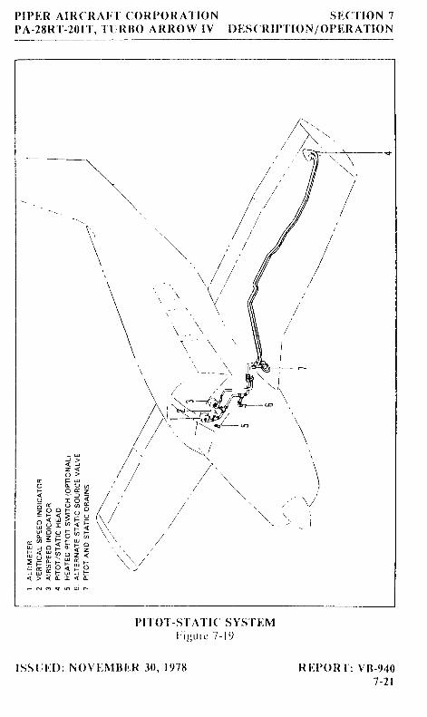
The system suppl ies both p i tot and stat ic pressure for the a i rspeed indi -cator , a l t imeter and ver t ica l speed indicator (when insta l led) .
Pitot and static pressure is picked up by the pitot head on the bottom ofthe left wing. An optional heated pitot head, which alleviares problems withicing or heavy rain, is available. The switch for pitot heat is iocated on theswitch panel. Push-button type pitot and static drains are located on thelower left sidewall of the cockpit.
An alternate static source is available as optional equipment. Thecontrol valve is located below the left side of the instrunrent panel. when thevalve is set in the alternate position, the altimeter, vertical speed indicatorand airspeed indicator wil l be using cabin air for static pressure. The stormwindow and cabin vents must be closed and the cabin heater and defrostermust be on during alternate static source operation. The altimeter error isless than 50 feet unless otherwise placarded.
To prevent bugs and water from entering the pitot pressure holes whenthe airplane is parked, a cover should be placed over the pitot head. Apartially or completely blocked pitot head wil l give erratic or zero readingson the instruments.
NOTE
During prefl ight, check to make sure the pitotcover is removed.
REPORT: VB-9407-20
ISSUED: NOVEMBER 30, 1978
PI I )ER A IRCRAI . " I ' C ( )RP( ) I I A I ' I 0NPA-28RT-2011 ' , 1 ' t JR I l ( ) ARROW lV
sl lc ' i loN 7I) I jS(]R I I '1 ' IO N /() I ' I ]R ATION
1,/ / ,
' . 1\ 1 .
@
\I
t . , " \ /
\.- t_, i
(-
\=*18.--4'w// \*-..._-(
, / t\..
\
/ , \
1/^ u t .) > /< J / /z < / /o > / /
E F V I /O L 9 o . /
i e g = / , 'H * ü 3 t / , ,= 9 ? F e " " / , /e ö H 6 ? 4 ' , \ /
- H ? ä F . k \ . /; x g [ - ; $ 1 \3 r f r s ä F a \ - , /{ > < [ r < t- e o g r i o s
Pt1 01 ' -S ' t -A1' t C SvS' , t I iMI : i gu rc 7 - l 9
lSS t l l , . l ) : NOVI tM I I ITR 30 , 1978 I t l , . l '0R' l ' : Vß-9, t07 -21
SECTION 7DESCRIPTION/ OPERATION
PIPER AIRCRAFT CORPORATIONPA.2tRT.2OIT. TURBO ARROW IV
lagIgigäalfurä,tEE8 ; S g S S t ä 8 9 9 ; g s * 9 9
, g
*ä:EeE,E'ää'ru*lu i d F c t o t c i ; c i c t + ü t O ; O " i ö
F F N d N N d d N d N d E
5r - [Ig . E s
,gälä*Fsgä*Fägr . i c i e ! t c r d d ö -
S g j
INSTRUMENT PANELFigure 7-21
ir.
ISSUED: NOVEMBER 30, 1978REVISED: AUGUST 15, l9E6
REPORT: VB-9407-22
/' '/'
'l ' r' r
x -------r--s-. rQ ;
* ____f--$.';li\ gr . : l]l IR - - - - f + u u i d ö
F7: i i ,n| 1 . . . . I . - Y l l
| - i 1 " , ' l lI ' ' o . , : . , " 'l , ^ ' ) 1 ' ' .
: = ) ' o-----_-_j-i-
- | f f i -": :T. r-t t ; -
I üsil?[:; rro'[n] I [;:-ffit1r=, 1 "ilfl +i,i- I t = l l * i l 1 ' , ' [ t . t ' l; =-il=iil.1'l u'J,'n fil't'lSqfllj Elli,Ell 'ht)'5"
. l t rl - -
I i ---------!--- b' itlr r{'@'t o '
l : R q +l : -=We;J; , rl-H€ml +l - f f i Ä 'l'-trqry&Hry,| \ \ = ^ q i _
l:--\-lV^-trll il| -\.\@ n lI| \v u-l-i-
._.-- J_
PIPER AIRCRAFT CORPORATIONPA-28RT-2OIT. TURBO ARR.OW IV
SECTION 7DESCRIPTION/ OPERATION
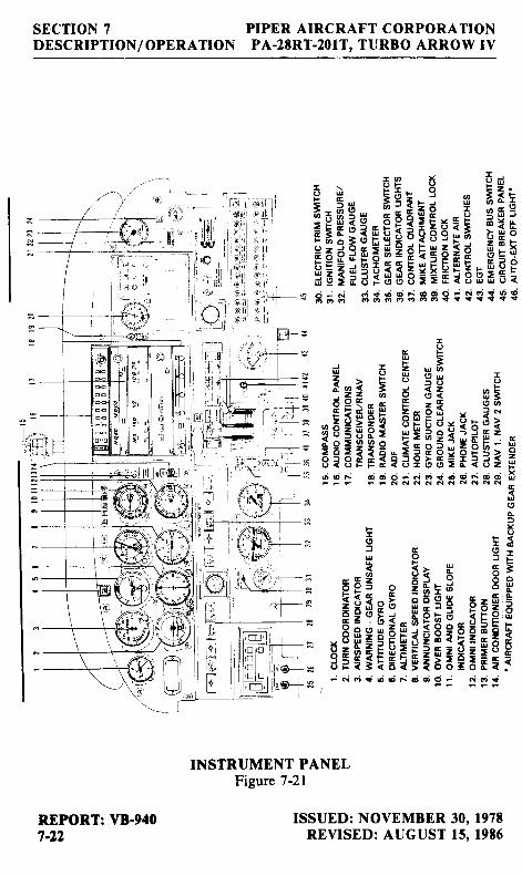
7.2I INSTRUMENT PANEL
The instrument panel is designed to accommodate the customaryadvanced fl ight instruments and the normally required power plant instru-ments. The artif icial horizon and directional gyro are vacuum operated andare located in the center of the left hand instrument panel. The vacuumgauge is located on the right hand instrument panel. The turn indicator, onthe left side, is electrically operated.
The radios are located in the center sect ion of the panei , and the c i rcu i tbreakers are in the lower right corner of the panel. An optional radio masterswitch is located near the top of the instrument panel between the radiostacks. It controls the power to all radios through the aircraft master switch.An emergency bus switch is also provided to provide auxil iary power to theavionics bus in event of a radio master switch circuit failure. The emergencybus switch is located behind the lower right shin guard left of the circuitbreaker panel .
An annunciator panel is mounted in the upper inst rument panel to warnthe p i lo t of a possib le mal funct ion in the a l ternator , o i l pressure, andvacuum systems. The overboost l ight is located beside the annuncratorpanel .
A ground clearance energy saver system is available to provide directpower to Comm #1 wi thout turn ing on the master swi tch. An internal ly l i tpushbut ton swi tch, located on the inst rument panel , prov ides annunciat ionfor engagement of the system. When the button is engaged direct aircraftbat tery power is appl ied to Comm #l audio ampl i f ier (speaker) and radioaccessories. The switch must be turned OFF or depletion of the battervcould resul t .
The manifold pressure l ine has a drain valve located behind and belowthe manifold pressure gauge. This allows any moisture which may havecollected from condensation to be pulled into the engine. This is accom-plished by depressing the valve for 5 seconds while operating the engine at1000 RPM.
NOTE
Do not depress the valve when manifold pres-sure exceeds 25 inches He.
ISSUED: NOVEMBER 30, l97tREVISED: JULY 15, 1982
REPORT: VB-9407-23
SECTION 7DESCRIPTION / OPERATION
PIPER AIRCRAFT CORPORATIONPA-28RT-2OIT. TT]RBO ARROW IV
-::::-='
1Ll-t-2
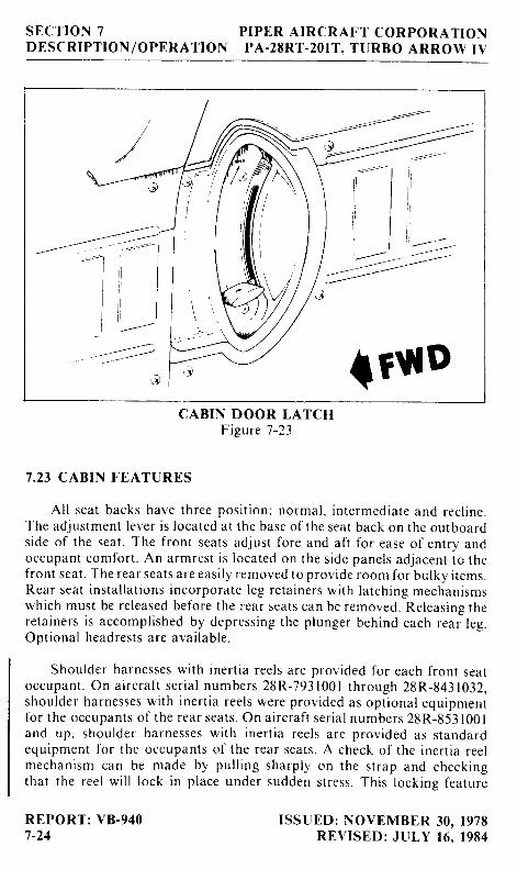
{rutPCABIN DOOR LATCH
Figure 7-23
7.23 CABIN FEATURES
Al l seat backs have three posi t ion: normal , in termediate and rec l ine.The adjustment lever is located at the base of the seat back on the outboardside of the seat. The front seats adjust fore and aft for ease of entry andoccupant comfor t . An armrest is located on the s idr : panels adjacent to thefront seat . The rear seats are easi ly removed to prov ide room for bulky i tems.Rear seat insta l la t ions incorporate leg reta iners wi t l i la tch ing mechanrsmswhich must be re leased before the rear seats can be removed. Releasing thereta iners is accompl ished by depressing the p lunger Lrehind each rear leg.Opt ional headrests are avai lable.
Shoulder harnesses wi th iner t ia reels are prov ided for each f ront seatoccupant . On a i rcraf t ser ia l numbers 28R-793 100 I through 28R-843 1032,shoulder harnesses wi th iner t ia reels were provided as opt ional equipmentfor the occupants of the rear seats. On a i rcraf t ser ia l numbers 28R-853 l00land up. shoulder harnesses wi th iner t ia reels are prov ided as standardequipment for the occupants of the rear seats. A check of the iner t ia reelmechanism can be made by pul l ing sharply on the st rap and checkingthat the reel wi l l lock in p lace under sudden st ress. This lock ing feature
REPORT: VB-9407-24
ISSUED: NOVEMBER 30, 1978REVISED: JULY 16. 1984
PIPER A IRCRAFT CORPORATIONPA-28RT.2OIT , TURBO ARROW IV
SECTION 7DESCRIPTION /OPERATION
prevents the st rap f rom extending and holds the occupant in p lace. Undernormal movement, the st rap wi l l extend and ret ract as requi red. On ear l iera i rcraf t prov ided wi th a s ingle st rap adjustable shoulder harness locatedabove the s ide window for each f ront seat , the shoulder s t rap is routed overthe shoulder adjacent to the window and at tached to the lap bel t in thegeneral area of the occupant 's h ip. Adjust th is f ixed st rap so that a l l contro lsare accessib le whi le mainta in ing adequate restra int for the occupant .Shoulder harnesses should be rout inely worn dur ing takeof f . landing, andwhenever an in f l ight emergenc) ' s i tuat ion occurs.
Addi t ional features inc lude p i lo t s torm window, two sun v isors, ashtrays for each occupant . map pockets located on the s ide panels below theinstrument panel , miscel laneous pockets on the rear of the f ront seat backs,armrests for the f ront occupants, cabin or baggage door locks and igni t ionlock .
The cabin door is double la tched. To c lose the cabin door . hold the doorc losed wi th the arm set whi le rnoving the s ide door la tch to the "LATCHED"posi t ion. Then engage the top la tch. Both la tches musl be secured beforefl ight.
7.25 BAGGAGf, AREA
A large baggage area, located behind the rear seats, is accessib le e i therf rom the cabin or through a large outs ide baggage door on the r ight s ide ofthe a i rcraf t . Maximum capaci ty is 200 lbs. T ie-down st raps are prov idedand should be used at a l l t imes.
NOl 'E
I t is the p i lo t 's responsib i l i ty to be sure whenthe baggage is loaded that the aircraft C.G. fallswi th in the a l lowable C.G. Range. (See Weightand Balance Sect ion.)
ISSUED: NOVEMBER 30, 1978REVISED: JULY 16. 1984
REPORT: VB-9407-25
SECTION 7DESCRIPTION/OPERATION
PIPER AIRCRAFT CORPORATIONPA-2ERT-2OIT. TURBO ARROW IV
q
q o
z u< L
o o< Äl .d zu O
\
\ -
)<--"---J ' . .
ql
IX
EU(9
+ ?o üE K
' \ "
\ \ r t
b < >
a^ Jo qJ O
3 => ss kd .- -r i :- z
f r 4 s> t r <= z A
3EHd F q i
- 'J
o 6F U =z 6 Yo o =
' ? 3 r ' 6: i < u j " ri s 1 = . 7 , 5
ä * E ä r o i ä r E g 5. E E : E q ö ! ä r ä ä ä i E: ; E ; ö o @ = { ; ; ; ö = A
i ; $ ; ? ä ä ä : $ $ $ ä ä i ig g s x + p p g ü g g g H p g- N t r j ? ( ; G t F d o g : : g : g
HEATING, VENTILATING AND DEFROSTING SYSTEMFigure 7-25
REPORT: VB-9407-26
ISSUED: NOVEMBER 30, l97EREVISED: SEPTEMBER 14. 1979
PIPER AIRCRAFT CORPORATIONPA-28RT-2OIT, TURBO ARROW IV
SECTION 7DESCRIPTION /OPERATION
7.27 HEATING, VENTILATING AND DEFROSTING SYSTEM
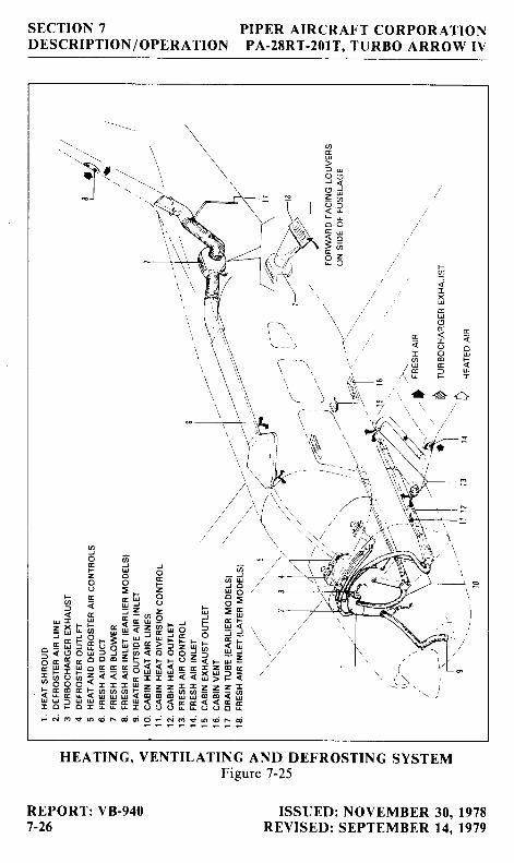
The heating system is designed to provide maximum comfort for theoccupants during winter and cool weather fl ights. The system includes a heatshroud, heat ducts, defroster outlets, heat and defroster controls.
CAUTION
When cabin heat is operated, heat duct surfacebecomes hot. This could result in burns if armsor legs are placed too close to heat duct outletsor surface.
An opening in the front of the lower cowl admits ram air to the heatershroud and then the air is ducted to the heater shut-offs on the right and leftside of the fire wall. When the shut-off s are opened the heated air then entersthe heat ducts located along each side of the center console. Outlets in theheat duct are located at each seat location. Airflow to the rear seats can beregulated by controls in the heat ducts located between the front seats. Thetemperature of the cabin is regulated by the heater control located on theright side of the instrument panel.
Defrosting is accomplished by heat outlets located on the right and leftside of the cowl cover. Heated air is ducted directly to defroster shut-offvalves at the fire wall, then to the defroster outlets. The airf low is regulatedby a defroster control located below the heat control.
To aid air distribution, the cabin air is exhausted overboard by an outletlocated on the bottom of the fuselage. Cabin exhaust outlets are locatedbelow and outboard ofthe rear seats. The above features are removed whenair condi t ion ing is insta l led.
An optional overhead ventilating system with outlets over each seat isalso available. An additional option to aid in fresh air circulation on modelswithout air conditioning is a cabin air blower to force air through the over-head vent system. This blower is operated by a fan switch with three posi-t ions - "OFF," "LOW," and "HIGH." The swi tch is located on the r ight s ideof the instrument panel with the heater and defroster controls.
ISSUED: NOVEMBER 30, l97tREVISED: SEPTEMBER 14. 1979
REPORT: VB-9407-27
SECTION 7DESCRIPT ION /OPERATION
PIPER A IRCRAFT CORPORATIONPA-28RT-2OIT , TT ]RBO ARROW I \ I
7 .29 STALL WARNING
An app roach ing s ta l l i s i nd i ca ted by a s ta l l wa rn ing ho rn wh i ch i sact ivated betu,een f ive and ten knots above sta l l speed. Mi ld a i r f ramebuf fet ing and gent le p i tch ing may a lso preccde thc sta l l . Sta l l speeds areshown on g raphs i n t he Pe r fo rmance Sec t i on . The s ta l lwa rn ing ho rn cm i t s acon t i nuous sound . The l and ing gea r wa rn ing ho rn i s d i f { ' e ren t i n t ha t i t em i t sa 90 cyc le pe r m inu te beep ing sound . The s ta l lwa rn ing ho rn i s ac t i va ted by al i f t detector insta l led on the leading edge of thc le f t u ' ing. Dur ing pref l ight .t he s ta l l wa rn ing sys tem shou ld be checked by t u rn ing the mas te r sw i t ch"ON. " l i f t i ng t he de tec to r and check ing to de te rm ine i f t he ho rn i s ac tua ted .
7 .3 I F IN ISH
Al l exter ior sur faces are pr imed wi th etching pr imer and f in ishcd wi thacr l ' l ic lacquer. An opt ional polyurethane f in ish is avai lable.
7 .33 A IR CONDIT IONING*
Thc a i r cond i t i on ing sys tem i s a rec i r cu la t i ng a i r sys tem. ' f hc ma jo rcomponcnts inc lude an evaporator , a condenser, a compressor , a b lower.swi tches and temperature contro ls .
- I -he evaporator is located behind the rear baggage compartment . T 'h is
coo l s t he a i r used fo r t he a i r cond i t i on ing sy ' s tem.
l .he condcnser is mountcd on a ret ractable scr ;op located on the bot tontof the f uselagc and to the rear of the baggage compartment area. The scoopextends whe n thc a i r condi t ioner is ON and ret racts to a f lush posi t ion whenthe system is OFF.
The compressor is mounted on the rear le f t s ide of the engine. l t has anelectr ic c lutch which automat ica l ly engages or d isengages the compressor tothe bel t dr ive system of the compressor .
*Op t i ona l equ ipmen l
REPORT: V8 -9407-28
ISSt iED: NOVEMBUR 30. 1978RE\ / ISED: J I ILY 16 . 1984
PIPER AIRCRAFT CORPORATIONPA-28RT-2OIT, TURBO ARROW IV
SECTION 7DESCRIPTION/OPERATION
Air f rom the baggage area is drawn through the evaporator by theblower and d is t r ibuted through an overhead duct to ind iv idual out le tslocated adjacent to each occupant .
The swi tches and temperature contro l are located on the lower r ight s ideof the inst rument panel in the c l imate contro l center panel . The temperaturecontro l regulates the temperature of the cabin. Turning the contro l c lock-wise increases cool ing; counterc lockwise decreases cool ing.
The fan speed swi tch and the a i r condi t ion ing ON-OFF swi tch areinboard of the temperature contro l . The fan can be operated independent lyof the a i r condi t ion ing; however, the fan must be on for a i r condi t ioneroperat ion. Turning e i ther s lv i tch of f wi l l d isengage the compressor c lutchand ret ract the condenser door . Cool ing a i r should be fe l t wi th in one minuteaf ter the a i r condi t ioner is turned on.
NOTE
If the system is not operat ing in 5 minutes, turnthe systern OFF unt i l the faul t is corrected.
The fan srv i tch a l lows operat ion of the fan wi th the a i r condi t ionerturned OFF to a id in cabin a i r c i rcu lat ion. "LOW" or "HIGH" can beselected to d i rect a f - low of a i r through the a i r condi t ioner out le ts in theoverhead duct . These out le ts can be adjusted or turned of l ind iv idual ly ' .
The condenser door l ight is located to the r ight of the engine inst rumentc luster in f ront of the p i lo t . The door l ight i l luminates when the door is openand is of l when the door is c losed.
A c i rcu i t breaker on the c i rcu i t breaker Danel Drotects the a i r condi-tioning electrical system.
Whenever 38 inches Hg or more manifold pressure is used a manifoldpressure swi tch d isengages the compressor and ret racts the scoop. Thisal lows maximum power and maximum rate of c l imb. The fan cont inues tooperate and the a i r wi l l remain cool for about one minute. When the throt t leis retarded so that less then 38 inches Hg manifold pressure is used, the clutchwi l l engage, the scoop wi l l extend, and the system wi l l again suppl l 'cool , dryal r .
ISSUED: NOVEMBER 30, 1978REVISED: JULY 15. 1982
REPORT: VB-9407-29
SECTION 7DESCRIPTION/OPER ATION
PIPER A IRCRAFT CORPORATIONPA-28RT-2OIT, TURBO ARROW IV
7.35 PIPER EXTERNAL POWER*
An opt ional s tar t ing insta l la t ion known as p iper External power ( pEp)is accessible through a receptacle located on the right side of the fuselage afio f the wing. An external bat tery can be connected to the socket , thusal lowing the operator to crank the engine wi thout having to gain access tothe airplane's battery.
7 .37 EMERGENCY LOCATOR TRANSMITTER*
The Emergency Locator Transmitter (ELT) meets the requirements ofFAR 91.52. It operates on self-contained batteries and is located in the alifuselage section. It is accessible through a rectangular cover on the righthand side. A number 2 Phil l ips screwdriver is requiied to remove the cover.
. A battery replacement date is marked on the transmitter. To complywith FAA regulations, the battery must be replaced on or before this dite.The battery must also be replaced if the transmitter has been used in anemergency situation or if the accumulated test t ime exceeds one hour, or ifthe unit has been inadvertently activated for an undetermined time period.
NOTE
If for any reason a test transmission isnecessary, the test transmission should beconducted only in the first f ive minutes of anyhour and l imi ted to three audio sweeps. l f testsmust be made at any other time, the tests shouldbe coordinated wi th the nearest FAA tower orfl ight service station.
NARCO ELT IO OPERATION
on the ELT unit itself is a three position switch placarded *oN," *oFF-and "ARM." The ARM posi t ion sets the ELT so that i t wi i l t ransmit af terimpact and wil l continue to transmit unti l i ts battery is drained. The ARMposition is selected when the ELT is installed in the airplane and it shouldremain in that position.
*Optional equipment
REPORT: VB-9407-30
ISSUED: NOVEMBER 30, lgTEREVISED: APRIL 13 . 1979
PIPER AIRCRAFT CORPORATIONPA-28RT.2OIT, TURBO ARROW IV
SECTION 7DESCRIPTION/OPERATION
To use the ELT as a portable unit in an emergency, remove the cover andunlatch the unit from its mounting base. The antenna cable is disconnectedby a left quarter-turn of the knurled nut and a pull. A sharp tug on the twosmall wires wil l break them loose. Deploy the self-contained antenna bypul l ing the p last ic tab marked "PULL FULLY TO EXTEND ANTENNA."Move the swi tch to ON to act ivate the t ransmit ter .
In the event the transmitter is activated by an impact, it can only beturned of f by moving the swi tch on the ELT uni t to OFF. Normal operat ioncan then be restored by pressing the small clear plastic reset button locatedon the top of the f ront face of the ELT and then moving the swi tch to AR M.
A pilot's remote switch located on the left side panel is provided to allowthe transmitter to be turned on from inside the cabin. The pilot's remoteswi tch is p lacarded "ON" and "ARMED." The swi tch is normal ly in theARMED posi t ion. Moving the swi tch to ON wi l l act ivate the t ransmit ter .Moving the swi tch back to the ARMED posi t ion wi l l turn of f the t ransmit reronly if the impact switch has not been activated.
The ELT should be checked to make certain the unit has not been acti-vated dur ing the ground check. Check by select ing 121.50 MHz on anoperating receiver. lf there is an oscii lating chirping sound, the ELT mayhave been activated and should be turned off immediately. This requiresremoval of the access cover and moving the switch to OFF, then press thereset button and return the switch to ARM. Recheck with the receiver roascertain the transmitter is silent.
CCC C IR I I - 2 OPERATION
On the unit itself is a three position selector switch placarded ,.OFF,"
"ARM" and "ON." The ARM posi t ion is prov ided to set the uni t to the auto-matic position so that it wil l transmit only after impact and wil l continue totransmit unti l the battery is drained to depletion or unti l the switch ismanual ly moved to the OFF posi t ion. The ARM posi t ion is se lected whenthe transmitter is installed at the factory and the switch should remain in thatposition whenever the unit is installed in the airplane. The ON position isprovided so the unit can be used as a portable transmitter or in theeventtheautomatic feature was not triggered by impact or to periodically test thefunction of the transmitter.
Select the OFF position when changing the battery, when rearming theunit if i t has been activated for any reason, or to discontinue transmission.
ISSUED: NOVEMBER 30, 197EREVISED: APRIL 13. 1979
REPORT: VB-9407_31
StrCTION 7 PIPER AIRCRAFT CORPORATIONDESCRIPTION/OPERATION PA-28RT_201T, TURBO ARROW rV
NOTE
If the switch has been placed in the ON positionfor any reason, the OFF position has to beselected before selecting ARM. If ARM isselected directly from the ON position, the unitwil l continue to transmit in the ARM position.
A pilot's remote switch, located on the left side paner, is provided toallow the transmitter to be controlled from inside the cabin. The pilot'sremote switch is placarded "ON," *AUTO/ARM"
and ..OFF/RESET.-The switch is normally left in the AUTo/ARM position. To turn the trans-mitter off, move the switch momentarily to the oFFi RESET position. Theaircraft master switch must be oN to turn the transmitter oFF. ro acruarethe transmitter for tests or other reasons, move the switch upward to the oNposition and leave it in that position as long as transmission is desired.
The unit is equipped with a portable antenna to allow the locator to beremoved from the aircraft in case of an emergency and used as a portablesignal transmitter.
The locator should be checked during the ground check to make certainthe unit has not been accidentally activated. check by tuning a radio receiverto 121.50 MHz. If there is an oscil lating sound, the locatoi may have beenactivated and should be rurned off immediately. Reset to the AIiM positionand check again to insure against outside interference.
REPORT: VB-9407-32
ISSUED: APRIL 13.1979