Embed Size (px)
Citation preview
November, 1 984 Supersedes Technical Data 36-711 dated December, 1 983, and Descriptive Bul letin 36-71 2 dated June, 1 978 Mai led to : E, D, C/36-600A
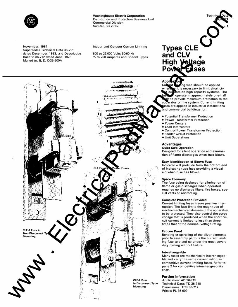
CLE-1 Fuse in Non-Disconnect Type Mounting
Westinghouse Electric Corporation Distribution and Protectio n Business Unit Commercial Division Sumter, SC 291 50
Indoor and Outdoor Current Limiti ng
600 to 23,000 Volts 50/60 Hz V2 to 750 Amperes and Special Types
CLE Family of Power Fuses.
CLE-2 Fuse in Disconnect Type Mounting
Technical Data 36-711
Types CLE and CLV High Voltage Power Fuses
Application
Page 1
Current l imiti ng fuse should be appl ied wherever it is necessary to l imit short circuit cu rrents on high capacity systems. The fuse wil l operate in approximately o ne-half cycle to provide maximum protection to the apparatus on the system. Cu rrent l imiti ng fuses are appl ied i n industrial insta l lations and commercial bui ldi ngs for:
• Potentia l Transformer Protection • Power Transformer Protection • Power Centers • Load Interrupters • Control Power Transformer Protection • Feeder Circuit Protection • Unit Substations
Advantages Quiet Safe Operation Designed for silent operation and elimi nation of flame discharges when fuse blows.
Easy Identification of Blown Fuse Indicator wi l l protrude from the bottom end of indicati ng type fuse providing a visual a id when fuse has blown.
Space Economy The fuse being designed for elimi nation of flame or gas discharges when operated, requires no discharge filters, fire boxes, special vents or reinforcing.
Complete Protection Provided Current limiti ng fuses i nsure positive i nterruption. The fuse l imits the magnitude of electro-mechanical stresses i n the apparatus to be protected. They a lso control the surge voltage that is produced when the short circuit current is l imited to less than three times that of the nomina l voltage rating.
Fatigue Proof Bending or spira l l ing of the silver elements prior to assembly permits the current l imiting fuse to stand up under the most severe duty cycl ing without fai lu re.
Interchangeable Many fuses a re mechanical ly in terchangeable and carry the same current rating as competitive current l imiti ng fuses. Refer to page 2 for competitive interchangeabi l ity chart.
Further Information Application: AD 36-7 1 5 Technical Data: T D 36-7 1 0 Dimensions: TCS 36-71 2 Prices: PL 36-609 www .
Elec
tricalP
artM
anua
ls . c
om

Technical Data 36-711
Page 2
Types CLE, CLV High Voltage Power Fuses
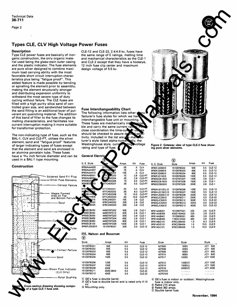
Description Type CLE power fuses are basically of inorganic con struction, the on ly organic material used bei ng the g lass-resin outer casing and the plastic indicator. The fuse elements are pure silver designed to combine maximum load carrying abi l ity with the most favorable short circu it interruption characteristics plus being "fatigue proof". This added feature is made possible by bending or spira l l ing the element prior to assembly, making the element structural ly stronger and distributing expansion u niformly to withstand the most severe type of duty cycl ing without fa i lu re. The CLE fuses are fi l led with a high purity silica sand of controlled g ra in size, and sandwiched between the sand fi l l ing is an additiona l layer of pulverant a rc quenching materia l . The addition of this band of fil ler to the fuse changes its melting characteristics, and facilitates low current i nterruption making it more suitable for transformer protection.
The non-indicating type of fuse, such as the BAL-1, CLV and CLE-PT, util izes the si lver element, sand and "fatigue proof" features of larger indicati ng types of fuses except that the element and sand are enclosed in an alumina porcelain tube. These fuses have a 13/,s inch ferrule diameter and can be used in a BAL-1 type mounting .
Construction
rr===c:=F=====';)- Soldered Sand Fill Plug �'-11--- Silver Fuse Elements
Magna Formed A rea on Top and Bottom Ferrules
�----Contact Ferrule
�LJ<1..,..'""".1L-- Blown Fuse Indicator (CLE Only)
Figure 1. Cross-section drawing showing component parts of a type CLE-1 fuse unit.
CLE-12 and CLE-22, 2.4/4.8 kv, fuses have the same range of E ratings, melting time and mechanical characteristics as the CLE-1 and CLE-2 except that they have a hookeye, 12 inch fuse clip center and maximum design voltage of 5.5 kv.
Fuse Interchangeability Chart The fol lowing information lists other manufactu rer's fuse styles for which we have an interchangeable fuse unit or mounting. These fuses are mechanically interchangeable and carry the same current rating. For close coordination the time-current curves should be checked to assure desired selectivity. Included in the l ist are the manufactu rer's style listed a lpha-numerically, the Westinghouse style, current rating, voltage rating and type of fuse.
General Electric
G. E. Style
9F60AAA005 9F60AAA007 9F60AAA010 9F60AAB001 9F60AAB002 9F60BDD001 9F60BDD003
9F60BDD905 9F60BDE905 9F60BHH001 9F60BHH905 9F60CCB015 9F60CCB020 9F60CCB025
9F60ECB030 9F60ECB040 9F60ECB050 9F60ECB065 9F60ECB080 9F60ECB100 9F60FJD030®
®
Style
677C593G02 677C593G03 677C593G04 677C592G03 677C592G04 677C452G06 677C453G07
677C452G01 677C452G02 677C452G08 677C452G03 678C240G01 678C240G02 678C240G03
449D797G02 449D797G12 449D797G03 449D797G04 449D797G05 449D797G06 151D978G01
ITE, Nelson and Bussman
®
Style Amps
151D978G01 30E 151D978G02 50E 151D978G03 65E 151D978G04 80E 151D978G05 100E
151D978G06 125E 151D978G07 150E 151D978G08 200E 151D978G11 250E/280X 151D978G13 400E
CD GE's fuse is double barrel.
Amps KV Fuse
5E .6 CLV 7E .6 CLV
tOE .6 CLV 1E 2.8 CLE·PT 2E 2.8 CLE·PT 1E 5.5 CLE-PT 3E 5.5 CLE·PT
.5E 5.5 CLE·PT .5E 8.3 CLE·PT 1E 15.5 CLE·PT
.5E 15.5 CLE·PT 15E 2.8 CLE 20E 2.8 CLE 25E 2.8 CLE
30E 2.8 CLE·1 40E 2.8 CLE·1 50E 2.8 CLE·1 65E 2.8 CLE·1 80E 2.8 CLE·1
100E 2.8 CLE·1 30E 5.5 CLE-12
KV Fuse
5.5 CLE·12 5.5 CLE-12 5.5 CLE·12 5.5 CLE-12 5.5 CLE-12
5.5 CLE·12 5.5 CLE-12 5.5 CLE-12 5.5 CLE-22 5.5 CLE-22
0 GE's fuse is double barrel and is rated only 4.16 kV.
@ Mounting only.
Figure 2: Cutaway view of type CLE-2 fuse showing pure silver elements.
®
G. E. Style Style Amps KV Fuse
9F60FJD050® 151D978G02 50E 5.5 CLE-12
9F60FJD065® 151D978G03 65E 5.5 CLE-12
9F60FJD080® 151D978G04 80E 5.5 CLE·12
9F60FJD100® 151D978G05 100E 5.5 CLE-12
9F60GCB125® 151D797G07 125E 2.8 CLE·1
9F60GCB150® 151D797G08 150E 2.8 CLE-1
9F60GCB200® 151D797G09 200E 2.8 CLE-1
9F60HJD125GJ® 151D978G06 125E 5.5 CLE-12 9F60HJD150GJ ® 151D978G07 150E 5.5 CLE-12
9F60HJD2QQ(i) ® 151D978G08 200E 5.5 CLE·12
9F60GJC250® 151D978G11 250E 5.5 CLE-22
9F60GJC300® 151D978G12 300E 5.5 CLE-22
9F60GJC325® 151D978G12 325X 5.5 CLE-22
9F60GJC400® 151D978G13 400E 5.5 CLE·22
9F61AAB301 151D907G01 225 2.8 CLE®
9F61AAB305 432D140A02 225 2.8 CLE®
9F61AAB401 151D909G01 450 2.8 CLE®
9F61AAB405 116D412A02 450 2.8 CLE®
9F61ABG101 676C236A02 1.5 8.3 CLE®
9F61ADG101 676C236A04 1.5 15.5 CLE®
9F61ADJ101 676C236A05 1.5 15.5 CLE@
Style Style Style
427505 30E5 JCY 30E
427508 50E5 JCY 50E
427509 65E5 JCY 65E
427510 80E5 JCY 80E
427511 100E5 JCY 100E
427512 125E50 JCY 125E
427515 150E50 JCY 150E 427516 200E5<Zl JCY 200E
427572® 427574®
@) GE's fuse is indoor or outdoor; Westinghouse fuse is indoor only.
® Rated 270 amps. ® Rated 362 amps. 0 Double barrel fuse.
November, 1984
�
'"'""
www . El
ectric
alPar
tMan
uals
. com
Cl Tech nica l Data
36-711
Page 3
Types CLE, CLV High Voltage Power Fuses
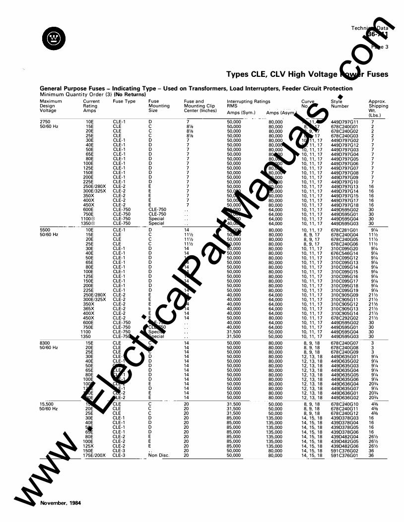
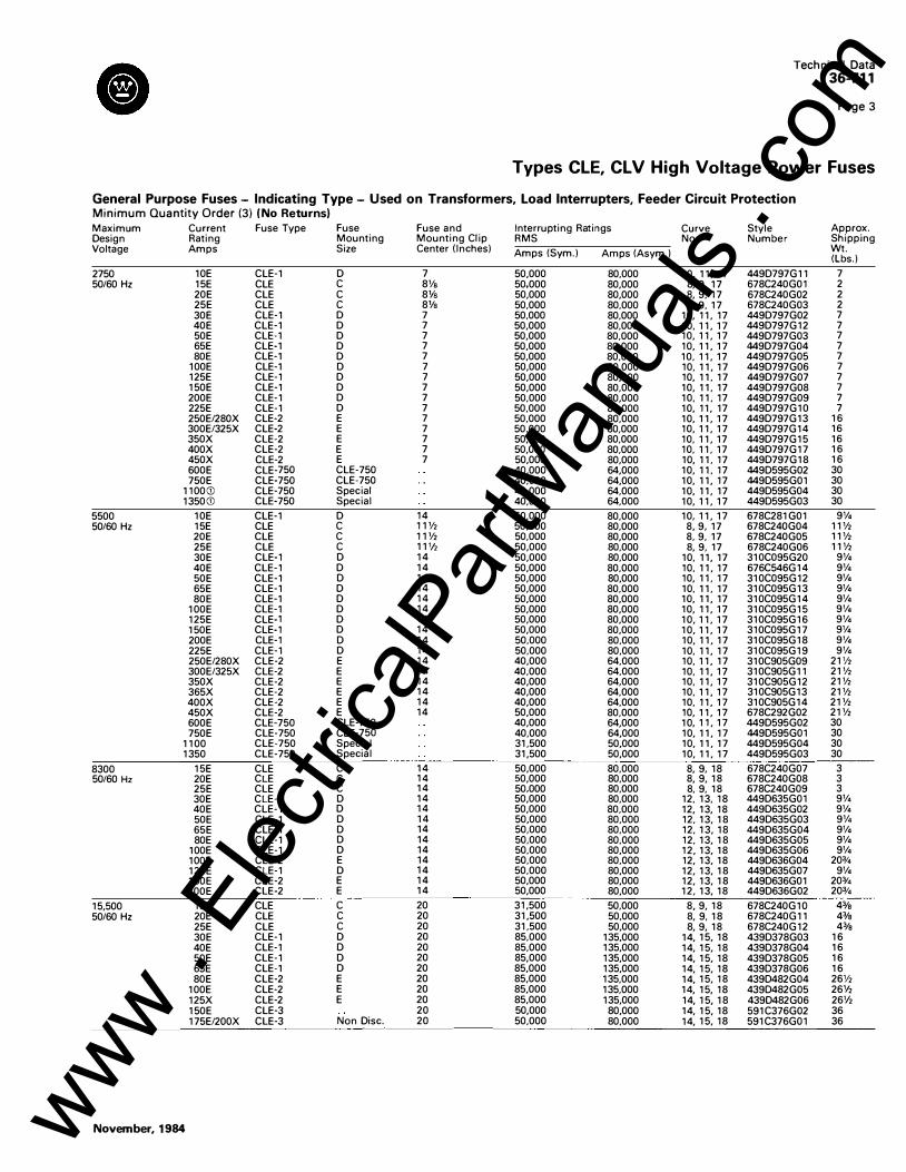
General Purpose Fuses - Indicating Type - Used on Transformers, Load Interrupters, Feeder Circuit Protection Mi nimum Quantity Order (3) (No Returns)
Maximum Current Fuse Type Fuse Fuse and Interrupting Ratings Curve Style Approx. Design Rating Mounting Mounting Clip RMS No. Number Shipping Voltage Amps Size Center (Inches) Amps (Sym.) Amps (Asym.) Wt.
(Lbs.)
2750 10E CLE-1 D 7 50,000 80,000 10, 11, 17 449D797G11 7 50/60Hz 15E CLE c 8Va 50,000 80,000 8, 9, 17 678C240G01 2
20E CLE c 8Va 50,000 80,000 8, 9, 17 678C240G02 2 25E CLE c 8Va 50,000 80,000 8, 9, 17 678C240G03 2 30E CLE-1 D 7 50,000 80,000 10, 11, 17 449D797G02 7 40E CLE-1 D 7 50,000 80,000 10, 11, 17 449D797G12 7 50E CLE-1 D 7 50,000 80,000 10, 11, 17 449D797G03 7 65E CLE-1 D 7 50,000 80,000 10, 11, 17 449D797G04 7 80E CLE-1 D 7 50,000 80,000 10, 11, 17 449D797G05 7
100E CLE-1 D 7 50,000 80,000 10, 11, 17 449D797G06 7 125E CLE-1 D 7 50,000 80,000 10, 11, 17 449D797G07 7 150E CLE-1 D 7 50,000 80,000 10, 11, 17 449D797G08 7 200E CLE-1 D 7 50,000 80,000 10, 11, 17 449D797G09 7 225E CLE-1 D 7 50,000 80,000 10, 11, 17 449D797G10 7 250E/280X CLE-2 E 7 50,000 80,000 10, 11, 17 449D797G13 16 300E/325X CLE-2 E 7 50,000 80,000 10, 11, 17 449D797G14 16 350X CLE-2 E 7 50,000 80,000 10, 11, 17 449D797G15 16 400X CLE-2 E 7 50,000 80,000 10, 11, 17 449D797G17 16 450X CLE-2 E 7 50,000 80,000 10, 11, 17 449D797G18 16 600E CLE-750 CLE-750 40,000 64,000 10, 11, 17 449D595G02 30 750E CLE-750 CLE-750 40,000 64,000 10, 11, 17 449D595G01 30
1100CD CLE-750 Special 40,000 64,000 10, 11, 17 449D595G04 30 1350CD CLE-750 Special 40,000 64,000 10, 11, 17 449D595G03 30
5500 10E CLE-1 D 14 50,000 80,000 10, 11, 17 678C281G01 9% 50/60Hz 15E CLE c llV2 50,000 80,000 8, 9, 17 678C240G04 11V2
20E CLE c llV2 50,000 80,000 8, 9, 17 678C240G05 11V2 25E CLE c l1V2 50,000 80,000 8, 9, 17 678C240G06 11% 30E CLE-1 D 14 50,000 80,000 10, 11, 17 310C095G20 9% 40E CLE-1 D 14 50,000 80,000 10, 11, 17 676C546G14 9% 50E CLE-1 D 14 50,000 80,000 10, 11, 17 310C095G12 9V• 65E CLE-1 D 14 50,000 80,000 10, 11, 17 310C095G13 9V• 80E CLE-1 D 14 50,000 80,000 10, 11, 17 310C095G14 9V•
100E CLE-1 D 14 50,000 80,000 10, 11, 17 310C095G15 9'/• 125E CLE-1 D 14 50,000 80,000 10, 11, 17 310C095G16 9% 150E CLE-1 D 14 50,000 80,000 10, 11, 17 310C095G17 9% 200E CLE-1 D 14 50,000 80,000 10, 11, 17 310C095G18 9% 225E CLE-1 D 14 50,000 80,000 10, 11, 17 310C095G19 9% 250E/280X CLE-2 E 14 40,000 64,000 10, 11, 17 310C905G09 21V2 300E/325X CLE-2 E 14 40,000 64,000 10, 11, 17 310C905G11 21V2 350X CLE-2 E 14 40,000 64,000 10, 11, 17 310C905G12 21V2 365X CLE-2 1:: 14 40,000 64,000 10, 11, 17 310C905G13 21V2 400X CLE-2 E 14 40,000 64,000 10, 11, 17 310C905G14 21V2 450X CLE-2 E 14 50,000 80,000 10, 11, 17 678C292G02 21V2 600E CLE-750 CLE-750 40,000 64,000 10, 11, 17 449D595G02 30 750E CLE-750 CLE-750 40,000 64,000 10, 11, 17 449D595G01 30
1100 CLE-750 Special 31,500 50,000 10, 11, 17 449D595G04 30 1350 CLE-750 Special 31,500 50,000 10, 11, 17 449D595G03 30
8300 15E CLE c 14 50,000 80,000 8, 9, 18 678C240G07 3 50/60Hz 20E CLE c 14 50,000 80,000 8, 9, 18 678C240G08 3
25E CLE c 14 50,000 80,000 8, 9, 18 678C240G09 3 30E CLE-1 D 14 50,000 80,000 12, 13, 18 449D635G01 9'14 40E CLE-1 D 14 50,000 80,000 12, 13, 18 449D635G02 9% 50E CLE-1 D 14 50,000 80,000 12, 13, 18 449D635G03 9'14 65E CLE-1 D 14 50,000 80,000 12, 13, 18 449D635G04 9'14 80E CLE-1 D 14 50,000 80,000 12, 13, 18 449D635G05 9%
100E CLE-1 D 14 50,000 80,000 12, 13, 18 449D635G06 9% 100E CLE-2 E 14 50,000 80,000 12, 13, 18 449D636G04 20% 125E CLE-1 D 14 50,000 80,000 12, 13, 18 449D635G07 9V4 150E CLE-2 E 14 50,000 80,000 12, 13, 18 449D636G01 20% 200E CLE-2 E 14 50,000 80,000 12, 13, 18 449D636G02 20%
15,500 15E CLE c 20 31,500 50,000 8, 9, 18 678C240G10 4% 50/60Hz 20E CLE c 20 31,500 50,000 8, 9, 18 678C240G11 43/a
25E CLE c 20 31,500 50,000 8, 9, 18 678C240G12 4% 30E CLE-1 D 20 85,000 135,000 14, 15, 18 439D378G03 16 40E CLE-1 D 20 85,000 135,000 14, 15, 18 439D378G04 16 50E CLE-1 D 20 85,000 135,000 14, 15, 18 439D378G05 16 65E CLE-1 D 20 85,000 135,000 14, 15, 18 439D378G06 16 80E CLE-2 E 20 85,000 135,000 14, 15, 18 439D482G04 26V2
lODE CLE-2 E 20 85,000 135,000 14, 15, 18 439D482G05 261/2 125X CLE-2 E 20 85,000 135,000 14, 15, 18 439D482G06 26V, 150E CLE-3 20 50,000 80,000 14, 15, 18 591C376G02 36 175E/200X CLE-3 Non Disc. 20 50,000 80,000 14, 15, 18 591C376G01 36
November, 1984 www . El
ectric
alPar
tMan
uals
. com

Technical Data
8 36-711
Page 4
� Types CLE, CLV High Voltage Power Fuses
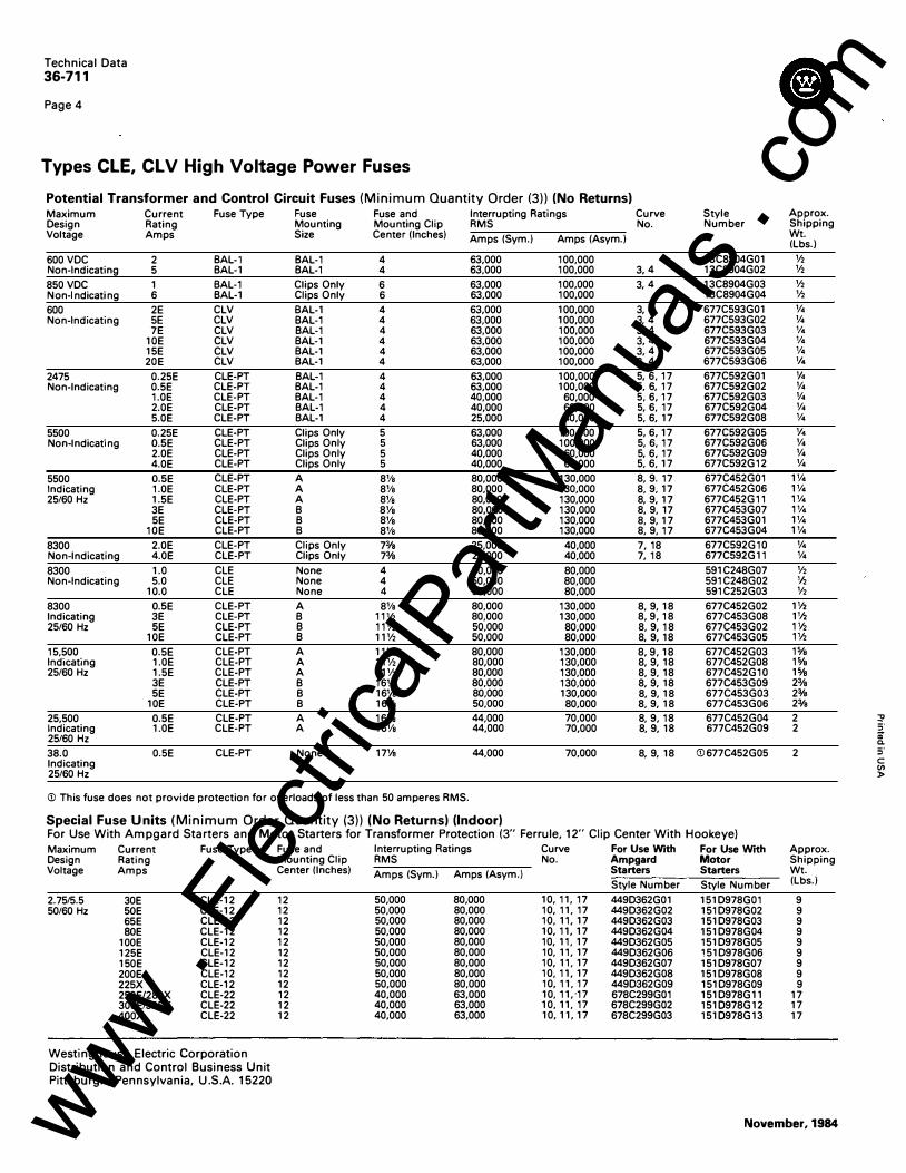
Potential Transformer and Control Circuit Fuses (Minimum Quantity Order (3)) (No Returns) Maximum Current Fuse Type Fuse Fuse and Interrupting Ratings Curve Style Approx. Design Rating Mounting Mounting Clip RMS No. Number Shipping Voltage Amps Size Center (Inches) Amps (Sym.) Amps (Asym.) Wt.
(Lbs.)
600 VDC 2 BAL-1 BAL-1 4 63,000 100,000 13C8904G01 Y2 Non-Indicating 5 BAL-1 BAL-1 4 63,000 100,000 3, 4 13C8904G02 V2
850 VDC 1 BAL-1 Clips Only 6 63,000 100,000 3, 4 13C8904G03 V2 Non-Ind icating 6 BAL-1 Clips Only 6 63,000 100,000 13C8904G04 V2
600 2E CLV BAL-1 4 63,000 100,000 3, 4 677C593G01 v. Non-Ind icating 5E CLV BAL-1 4 63,000 100,000 3, 4 677C593G02 v.
7E CLV BAL-1 4 63,000 100,000 3, 4 677C593G03 v. 10E CLV BAL-1 4 63,000 100,000 3, 4 677C593G04 v. 15E CLV BAL-1 4 63,000 100,000 3, 4 677C593G05 v. 20E CLV BAL-1 4 63,000 100,000 3, 4 677C593G06 v.
2475 0.25E CLE-PT BAL-1 4 63,000 100,000 5, 6, 17 677C592G01 v. Non-Indicating 0.5E CLE-PT BAL-1 4 63,000 100,000 5, 6, 17 677C592G02 v.
1.0E CLE-PT BAL-1 4 40,000 60,000 5, 6, 17 677C592G03 v. 2.0E CLE-PT BAL-1 4 40,000 60,000 5, 6, 17 677C592G04 v. 5.0E CLE-PT BAL-1 4 25,000 40,000 5, 6, 17 677C592G08 v.
5500 0.25E CLE-PT Clips Only 5 63,000 100,000 5, 6, 17 677C592G05 v. Non-Indicating 0.5E CLE-PT Clips Only 5 63,000 100,000 5, 6, 17 677C592G06 v.
2.0E CLE-PT Clips Only 5 40,000 60,000 5, 6, 17 677C592G09 v. 4.0E CLE-PT Clips Only 5 40,000 60,000 5, 6, 17 677C592G12 v.
5500 0.5E CLE-PT A 8Va 80,000 130,000 8, 9. 17 677C452G01 1% Indicating 1.0E CLE-PT A 8Va 80,000 130,000 8, 9, 17 677C452G06 1% 25/60 Hz 1.5E CLE-PT A 8Vs 80,000 130,000 8, 9, 17 677C452G11 1%
3E CLE-PT B 8Va 80,000 130,000 8, 9, 17 677C453G07 1% 5E CLE-PT B 8Va 80,000 130,000 8, 9, 17 677C453G01 1%
10E CLE-PT B 8Va 80,000 130,000 8, 9, 17 677C453G04 1%
8300 2.0E CLE-PT Clips Only 73fs 25,000 40,000 7, 18 677C592G10 v. Non-Ind icating 4.0E CLE-PT Clips Only 73fs 25,000 40,000 7, 18 677C592G11 v. 8300 1.0 CLE None 4 50,000 80,000 591C248G07 V2 Non-Indicating 5.0 CLE None 4 50,000 80,000 591C248G02 V2
10.0 CLE None 4 50,000 80,000 591C252G03 Y2 8300 0.5E CLE-PT A 8Vs 80,000 130,000 8, 9, 18 677C452G02 1V2 Ind icating 3E CLE-PT B 11% 80,000 130,000 8, 9, 18 677C453G08 1V2 25/60 Hz 5E CLE-PT B 11% 50,000 80,000 8, 9, 18 677C453G02 1V2
10E CLE-PT B 11V2 50,000 80,000 8, 9, 18 677C453G05 1112
15,500 0.5E CLE-PT A 11V2 80,000 130,000 8, 9, 18 677C452G03 1% Indicating 1.0E CLE-PT A 11V2 80,000 130,000 8, 9, 18 677C452G08 1% 25/60 Hz 1.5E CLE-PT A 11V2 80,000 130,000 8, 9, 18 677C452G10 1%
3E CLE-PT B 16Vs 80,000 130,000 8, 9, 18 677C453G09 23/s 5E CLE-PT B 161/s 80,000 130,000 8, 9, 18 677C453G03 23fs
10E CLE-PT B 16Vs 50,000 80,000 8, 9, 18 677C453G06 23fs
25,500 0.5E CLE-PT A 16Vs 44,000 70,000 8, 9, 18 677C452G04 2 :!' Ind icating 1.0E CLE-PT A 161/s 44,000 70,000 8, 9, 18 677C452G09 2 3 25/60 Hz <D a. 38.0 0.5E CLE-PT None 17Vs 44,000 70,000 8, 9, 18 <D677C452G05 2 3 Ind icating c
(f) 25/60 Hz }>
G) This fuse does not provid e protection for overloads of less than 50 amperes RMS.
Special Fuse Units (Minimum Order Quantity (3)) (No Returns) (Indoor) For Use With Ampgard Starters and Motor Starters for Transformer Protection (3" Ferru le, 1 2" Clip Center With Hookeye) Maximum Current Fuse Type Fuse and Interrupting Ratings Curve For Use With For Use With Approx. Design Rating Mounting Clip RMS No. Ampgard Motor Shipping Voltage Amps Center (Inches) Amps (Sym.) Amps (Asym.) Starters Starters Wt.
Style Number Style Number (Lbs. )
2.75/5.5 30E CLE-12 12 50,000 80,000 10, 11, 17 449D362G01 151D978G01 9 50/60Hz 50E CLE-12 12 50,000 80,000 10, 11, 17 449D362G02 151D978G02 9
65E CLE-12 12 50,000 80,000 10, 11, 17 449D362G03 151D978G03 9 80E CLE-12 12 50,000 80,000 10, 11, 17 449D362G04 151D978G04 9
100E CLE-12 12 50,000 80,000 10, 11, 17 449D362G05 151D978G05 9 125E CLE-12 12 50,000 80,000 10, 11, 17 449D362G06 151D978G06 9 150E CLE-12 12 50,000 80,000 10, 11, 17 449D362G07 151D978G07 9 200E CLE-12 12 50,000 80,000 10, 11, 17 449D362G08 151D978G08 9 225X CLE-12 12 50,000 80,000 10, 11, 17 449D362G09 151D978G09 9 250E/280X CLE-22 12 40,000 63,000 10, 11,·17 678C299G01 151D978G11 17 300E/325X CLE-22 12 40,000 63,000 10, 11, 17 678C299G02 151D978G12 17 400X CLE-22 12 40,000 63,000 10, 11, 17 678C299G03 151D978G13 17
'"""""' Westinghouse E lectric Corporation Distribution and Protection Busi ness Unit Commercia l Division Sumter, SC 291 50
November, 1984 www . El
ectric
alPar
tMan
uals
. com
November, 1984 Su persedes Technical Data 36-711 dated December, 1983, and Descriptive Bul letin 36-7 1 2 dated Ju ne, 1978 Mailed to : E, D, C/36-600A. B, C
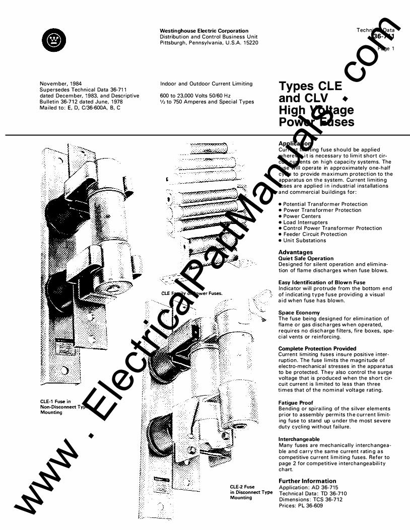
CLE-1 Fuse in Non-Disconnect Type Mounting
Westinghouse Electric Corporation Distribution and Control Business U nit Pittsburgh, Pennsylvania, U .S.A. 15220
Indoor and Outdoor Current Limiting
600 to 23,000 Volts 50/60 Hz 1/2 to 750 Amperes and Special Types
C1.E Family of Power Fuses.
CLE-2 Fuse in Disconnect Type Mounting
Technical Data 36-711
Types CLE and CLV High Voltage Power Fuses
Application
Page 1
Current l imiting fuse should be applied wherever it is necessary to l imit short circuit currents on high capacity systems. The fuse wil l operate in approximately o ne-half cycle to provide maximum protection to the apparatus on the system. Current l imitin g fuses are applied i n industrial installations and commercial bui ldings for :
• Potential Tran sformer Protection • Power Transformer Protection • Power Centers • Load I nterrupters • Control Power Transformer Protection • Feeder Circuit Protection • Unit Su bstations
Advantages Quiet Safe Operation Designed for s i lent operation and el imination of flame discharges when fuse blows.
Easy Identification of Blown Fuse Indicator wi l l protrude from the bottom end of indicating type fuse providing a visual aid when fuse has blown.
Space Economy The fuse being design ed for elimination of flame or gas discharges when operated, requires no discharge filters, fire boxes, special vents or reinforcing .
Complete Protection Provided Current limiting fuses insure positive i nterruption . The fuse l imits the magnitude of electro-mechanical stresses in the apparatus to be protected. They also control the surg e voltage that is produced when the short circuit current is limited to less than three times that of the nominal voltage rating.
Fatigue Proof Bending or spirall ing of the silver elements prior to assembly permits the current limiting fuse to stand up u nder the most severe duty cycling without fai l u re.
Interchangeable Many fuses are mechanical ly interchangeable and carry the same current ratin g as competitive current limiting fuses. Refer to page 2 for competitive interchangeability chart.
Further Information Appl ication: AD 36-715 Technical Data: TD 36-71 0 Dimensions: TCS 36-7 1 2 Prices: PL 36-609 www .
Elec
tricalP
artM
anua
ls . c
om
Technical Data 36-711
Page 2
Types CLE, CLV High Voltage Power Fuses
Description Type CLE power fuses are basically of inorganic construction, the only organic material used being the glass-resin outer casing and the plastic indicator. The fuse elements are pure silver designed to combine maximum load carrying ability with the most favorable short circuit interruption characteristics plus being "fatigue proof". This added feature is made possible by bending or spiralling the element prior to assembly, making the element structurally stronger and distributing expansion uniformly to withstand the most severe type of duty cycling without failure. The CLE fuses are filled with a high purity silica sand of controlled grain size, and sandwiched between the sand filling is an additional layer of pulverant arc quenching material. The addition of this band of filler to the fuse changes its melting characteristics, and facilitates low current interruption making it more suitable for transformer protection.
The non-indicating type of fuse, such as the BAL-1, CLV and CLE-PT, utilizes the silver element, sand and "fatigue proof" features of larger indicating types of fuses except that the element and sand are enclosed in an alumina porcelain tube. These fuses have a 13/,a inch ferrule diameter and can be used in a BAL-1 type mounting.
Construction
rF==c=:F::::::;=;;;-- Soldered Sand Fill P l ug · r.,.:.U.--- Si lver Fuse Elements
Magna Formed Area on Top and Bottom Ferrules
Figure 1 . Cross-section drawing showing component parts of a type CLE-1 fuse unit.
CLE-12 and CLE-22, 2.4/4.8 kv, fuses have the same range of E ratings, melting time and mechanical characteristics as the CLE-1 and CLE-2 except that they have a hookeye, 12 inch fuse clip center and maximum design voltage of 5.5 kv.
Fuse Interchangeability Chart The following information lists other manu-facturer's fuse styles for which we have an interchangeable fuse unit or mounting. These fuses are mechanically interchangea-ble and carry the same current rating. For close coordination the time-current curves should be checked to assure desired selec-tivity. Included in the list are the manufac-turer's style listed alpha-numerically, the Westinghouse style, current rating, voltage rating and type of fuse.
General Electric
®
G. E. Style Style Amps KV Fuse
9FSOAAA005 S77C593G02 SE .s CLV 9FSOAAA007 S77C593G03 7E .s CLV 9FSOAAA010 S77C593G04 10E .s CLV 9FSOAAB001 S77C592G03 1E 2.8 CLE-PT 9F60AAB002 S77C592G04 2E 2.8 CLE-PT 9FSOBDD001 S77C452GOS 1E 5.5 CLE-PT 9F60BDD003 677C453G07 3E 5.S CLE-PT
9F60BDD905 677C452G01 .5E 5.5 CLE-PT 9FSOBDE905 S77C452G02 .5E 8.3 CLE-PT 9FSOBHH001 677C452G08 1E 1S.5 CLE-PT 9F608HH905 677C4S2G03 .se 15.5 CLE-PT 9FSOCCB015 S78C240G01 15E 2.8 CLE 9F60CCB020 678C240G02 20E 2.8 CLE 9F60CCB025 678C240G03 25E 2.8 CLE
9F60ECB030 4490797G02 30E 2.8 CLE-1 9FSOECB040 4490797G12 40E 2.8 CLE-1 9FSOECB050 4490797G03 50E 2.8 CLE-1 9FSOECBOS5 4490797G04 SSE 2.8 CLE-1 9F60ECB080 4490797G05 SOE 2.8 CLE-1 9FSOECB100 4490797G06 100E 2.8 CLE-1 9FSOFJ00300 1S1D978G01 30E 5.5 CLE-12
ITE, Nelson and Bussman
®
Style Amps KV Fuse
1S1D978G01 30E 5.5 CLE-12 1510978G02 50E 5.S CLE-12 151D978G03 S5E 5.5 CLE-12 151D978G04 aoe 5.S CLE-12 151D978G05 100E 5.5 CLE-12
1510978GOS 125E 5.5 CLE-12 1510978G07 150E 5.S CLE-12 1S10978G08 200E 5.S CLE-12 1510978G11 250E/280X S.5 CLE-22 1510978G13 400E S.5 CLE-22
<D GE's fuse is double barrel. ® GE's fuse is double barrel and is rated only 4.16
kV. @ Mounting only.
Cl
Figure 2: Cutaway view of type CLE-2 fuse show-ing pure silver elements.
® KV Fuse G. E. Style Style Amps
9FSOFJD0500 1510978G02 SOE 5.5 CLE-12
9FSOFJDOS50 1510978G03 SSE 5.5 CLE-12
9F60FJ00800 1510978G04 SOE 5.5 CLE-12
9FSOFJD1000 1510978G05 100E 5.5 CLE-12
9F60GCB1250 1510797G07 125E 2.8 CLE-1
9FSOGCB1S00 1S10797G08 150E 2.8 CLE-1
9F60GCB2000 1510797G09 200E 2.8 CLE-1
9F60HJD125Ql@ 1S10978GOS 125E 5.5 CLE-12
9FSOHJD1SOQl0 1S1D978G07 1SOE S.5 CLE-12
9FSOHJ 0200 Ql@ 1S10978G08 200E 5.5 CLE-12
9F60GJC250® 1510978G11 250E 5.5 CLE-22
9FSOGJC300® 151D978G12 300E s.s CLE-22
9FSOGJC32S® 1510978G12 32SX 5.5 CLE-22
9FSOGJC400® 1510978G13 400E 5.5 CLE-22
9FS1AAB301 1S1D907G01 225 2.8 CLE®
9F61AAB30S 4320140A02 225 2.8 CLE®
9FS1AAB401 1510909G01 450 2.8 CLE®
9FS1AAB405 116D412A02 450 2.8 CLE®
9FS1ABG101 S7SC236A02 1.5 8.3 CLE®
9FS1ADG101 676C236A04 1.5 15.5 CLE®
9F61ADJ101 676C236A05 1.S 15.5 CLE®
Style Style Style
427S05 30E5 JCY 30E
427508 50E5 JCY SOE
427509 65E5 JCY SSE
427510 aces JCY 80E
427511 100E5 JCY 100E
427512 125ESCD JCY 125E
42751S 150E5® JCY 150E
427S16 200E5C!l JCY 200E
427572@
427S74®
@) GE's fuse is indoor or outdoor; Westinghouse fuse is indoor only.
® Rated 270 amps. ® Rated 362 amps. ® Double barrel fuse.
November, 1984 www . El
ectric
alPar
tMan
uals
. com
f) Technical Data
36-711
Page 3
Types CLE, CLV High Voltage Power Fuses
General Purpose Fuses - Indicating Type - Used on Transformers, Load Interrupters, Feeder Circuit Protection Minimum Quantity Order (3) (No Returns) Maximum Current Fuse Type Fuse Fuse and Design Rating Mounting Mounting Clip Voltage Amps Size Center (Inches)
2750 10E CLE-1 D 7 50/60Hz 15E CLE c 8Vs
20E CLE c 8Vs 25E CLE c 8Vs 30E CLE-1 D 7 40E CLE-1 D 7 50E CLE-1 D 7 65E CLE-1 D 7 80E CLE-1 D 7
100E CLE-1 D 7 125E CLE-1 D 7 150E CLE-1 D 7 200E CLE-1 D 7 225E CLE-1 D 7 250E/280X CLE-2 E 7 300E/325X CLE-2 E 7 350X CLE-2 E 7 400X CLE-2 E 7 450X CLE-2 E 7 600E CLE-750 CLE-750 750E CLE-750 CLE-750
1100()) CLE-750 Special 1350CD CLE-750 Special
5500 10E CLE-1 D 14 50/60Hz 15E CLE c 11 V2
20E CLE c 11 V2 25E CLE c 11'12 30E CLE-1 D 14 40E CLE-1 D 14 50E CLE-1 D 14 65E CLE-1 D 14 80E CLE-1 D 14
100E CLE-1 D 14 125E CLE-1 D 14 150E CLE-1 D 14 200E CLE-1 D 14 225E CLE-1 D 14 250E/280X CLE-2 E 14 300E/325X CLE-2 E 14 350X CLE-2 E 14 365X CLE-2 E 14 400X CLE-2 E 14 450X CLE-2 E 14 600E CLE-750 CLE-750 750E CLE-750 CLE-750
1100 CLE-750 Special 1350 CLE-750 Special
8300 15E CLE c 14 50/60Hz 20E CLE c 14
25E CLE c 14 30E CLE-1 D 14 40E CLE-1 D 14 50E CLE-1 D 14 65E CLE-1 D 14 80E CLE-1 D 14
100E CLE-1 D 14 100E CLE-2 E 14 125E CLE-1 D 14 150E CLE-2 E 14 200E CLE-2 E 14
15,500 15E CLE c 20
50/60Hz 20E CLE c 20 25E CLE c 20 30E CLE-1 D 20 40E CLE-1 D 20 50E CLE-1 D 20 65E CLE-1 D 20 80E CLE-2 E 20
100E CLE-2 E 20 125X CLE-2 E 20 150E CLE-3 20 175E/200X CLE-3 Non Disc. 20
November, 1984
Interrupting Ratings RMS
Amps (Sym.) Amps (Asym.)
50,000 80,000 50,000 80,000 50,000 80,000 50,000 80,000 50,000 80,000 50,000 80,000 50,000 80,000 50,000 80,000 50,000 80,000 50,000 80,000 50,000 80,000 50,000 80,000 50,000 80,000 50,000 80,000 50,000 80,000 50,000 80,000 50,000 80,000 50,000 80,000 50,000 80,000 40,000 64,000 40,000 64,000 40,000 64,000 40,000 64,000
50,000 80,000 50,000 80,000 50,000 80,000 50,000 80,000 50,000 80,000 50,000 80,000 50,000 80,000 50,000 80,000 50,000 80,000 50,000 80,000 50,000 80,000 50,000 80,000 50,000 80,000 50,000 80,000 40,000 64,000 40,000 64,000 40,000 64,000 40,000 64,000 40,000 64,000 50,000 80,000 40,000 64,000 40,000 64,000 31,500 50,000 31,500 50,000
50,000 80,000 50,000 80,000 50.000 80,000 50,000 80,000 50,000 80,000 50,000 80,000 50,000 80,000 50,000 80,000 50,000 80,000 50,000 80,000 50,000 80,000 50,000 80,000 50,000 80,000
31,500 50,000 31,500 50,000 31,500 50,000 85,000 135,000 85,000 135,000 85,000 135,000 85,000 135,000 85,000 135,000 85,000 135,000 85,000 135,000 50,000 80,000 50,000 80,000
Curve No.
10, 11, 17 8, 9, 17 8, 9, 17 8, 9, 17
10, 11, 17 10, 11, 17 10, 11, 17 10, 11, 17 10, 11, 17 10, 11, 17 10, 11, 17 10, 11, 17 10, 11, 17 10, 11, 17 10, 11, 17 10, 11, 17 10, 11, 17 10, 11, 17 10, 11, 17 10, 11, 17 10, 11, 17 10, 11, 17 10, 11, 17
10, 11, 17 8, 9, 17 8, 9, 17 8, 9, 17
10, 11, 17 10, 11, 17 10, 11, 17 10, 11, 17 10, 11, 17 10, 11, 17 10, 11, 17 10, 11, 17 10, 11, 17 10, 11, 17 10, 11, 17 10, 11, 17 10, 11, 17 10, 11, 17 10, 11, 17 10, 11, 17 10, 11, 17 10, 11, 17 10, 11, 17 10, 11, 17
8, 9, 18 8, 9, 18 8, 9, 18
12, 13, 18 12, 13, 18 12, 13, 18 12, 13, 18 12, 13, 18 12, 13, 18 12, 13, 18 12, 13, 18 12, 13, 18 12, 13, 18
8, 9, 18 8, 9, 18 8, 9, 18
14, 15, 18 14, 15, 18 14, 15, 18 14, 15, 18 14, 15, 18 14, 15, 18 14, 15, 18 14, 15, 18 14, 15, 18
Style Approx. Number Shipping
Wt. (lbs.)
449D797G11 7 678C240G01 2 678C240G02 2 678C240G03 2 449D797G02 7 449D797G12 7 449D797G03 7 449D797G04 7 449D797G05 7 449D797G06 7 449D797G07 7 449D797G08 7 449D797G09 7 449D797G10 7 449D797G13 16 449D797G14 16 449D797G15 16 449D797G17 16 449D797G18 16 449D595G02 30 449D595G01 30 449D595G04 30 449D595G03 30
678C281G01 9% 678C240G04 11V2 678C240G05 11V2 678C240G06 11V2 310C095G20 9V. 676C546G14 9V• 310C095G12 9% 310C095G13 9% 310C095G14 9% 310C095G15 9% 310C095G16 9% 310C095G17 9% 310C095G18 9% 310C095G19 9% 310C905G09 21'12 310C905G11 21V2 310C905G12 21V2 310C905G13 21V2 310C905G14 21V2 678C292G02 21V2 449D595G02 30 449D595G01 30 449D595G04 30 449D595G03 30
678C240G07 3 678C240G08 3 678C240G09 3 449D635G01 9V. 449D635G02 9% 449D635G03 9V• 449D635G04 9% 449D635G05 9% 449D635G06 9% 449D636G04 20314 449D635G07 9% 449D636G01 20% 449D636G02 20314
678C240G10 4% 678C240G11 4% 678C240G12 4% 439D378G03 16 439D378G04 16 439D378G05 16 439D378G06 16 439D482G04 26112 439D482G05 26'12 439D482G06 26112 591C376G02 36 591C376G01 36
www . El
ectric
alPar
tMan
uals
. com
Technical Data 36-711
Page 4
Types CLE, CLV High Voltage Power Fuses
Potential Transformer and Control Circuit Fuses (Minimum Quantity Order (3)) (No Returns) Maximum Current Fuse Type Fuse Fuse and Interrupting Ratings Design Rating Mounting Mounting Clip RMS Voltage Amps Size Center (Inches) Amps (Sym.) Amps (Asym.)
600 VDC 2 BAL-1 BAL-1 4 63,000 100,000 Non-Indicating 5 BAL-1 BAL-1 4 63,000 100,000
850 VDC 1 BAL-1 Clips Only 6 63,000 100,000 N on-1 ndicati ng 6 BAL-1 Clips Only 6 63,000 100,000
600 2E CLV BAL-1 4 63,000 100,000 Non-Indicating 5E CLV BAL-1 4 63,000 100,000
7E CLV BAL-1 4 63,000 100,000 10E CLV BAL-1 4 63,000 100,000 15E CLV BAL-1 4 63,000 100,000 20E CLV BAL-1 4 63,000 100,000
2475 0.25E CLE-PT BAL-1 4 63,000 100,000 Non-Indicating 0.5E CLE-PT BAL-1 4 63,000 100,000
1.0E CLE-PT BAL-1 4 40,000 60,000 2.0E CLE-PT BAL-1 4 40,000 60,000 5.0E CLE-PT BAL-1 4 25,000 40,000
5500 0.25E CLE-PT Clips Only 5 63,000 100,000 Non-lndicati ng O.SE CLE-PT Clips Only 5 63,000 100,000
2.0E CLE-PT Clips Only 5 40,000 60,000 4.0E CLE-PT Clips Only 5 40,000 60,000
5500 O.SE CLE-PT A 8Va 80,000 130,000 Indicating 1.0E CLE-PT A 8Va 80,000 130,000 25/60 Hz 1.5E CLE-PT A BVa 80,000 130,000
3E CLE-PT B 8Ve 80,000 130,000 SE CLE-PT B BVe 80,000 130,000
10E CLE-PT B 8Va 80,000 130,000
8300 2.0E CLE-PT Clips Only 73fe 25,000 40,000 Non-Indicating 4.0E CLE-PT Clips Only 73fe 25,000 40,000
8300 1.0 CLE None 4 50,000 80,000 Non-Indicating 5.0 CLE None 4 50,000 80,000
10.0 CLE None 4 50,000 80,000
8300 O.SE CLE-PT A 8Va 80,000 130,000 Indicating 3E CLE-PT B 111/2 80,000 130,000 25/60 Hz SE CLE-PT B 11V2 50,000 80,000
10E CLE-PT B 11V2 50,000 80,000
15,500 0.5E CLE-PT A 11Y2 80,000 130,000 Indicating 1.0E CLE-PT A 11Y2 80,000 130,000 25/60 Hz 1.5E CLE-PT A 11Y2 80,000 130,000
3E CLE-PT B 16Vs 80,000 130,000 SE CLE-PT B 16% 80,000 130,000
10E CLE-PT B 16Ye 50,000 80,000
25,500 O.SE CLE-PT A 16Ye 44,000 70,000 Indicating 1.0E CLE-PT A 16Ye 44,000 70,000 25/60 Hz
38.0 0.5E CLE-PT None 17Vs 44,000 70,000 Indicating 25/60 Hz
G) This fuse does not provide protection for overloads of less than 50 amperes RMS.
Special Fuse Units (Minimum Order Quantity (3)) (No Returns) (Indoor)
Curve Style Approx. No. Number Shipping
Wt. (Lbs.)
13C8904G01 V2 3, 4 13C8904G02 V2
3, 4 13C8904G03 V2 13C8904G04 V2
3, 4 677C593G01 v. 3, 4 677C593G02 v. 3, 4 677C593G03 % 3, 4 677C593G04 % 3, 4 677C593G05 % 3, 4 677C593G06 'I• 5, 6, 17 677C592G01 v. 5, 6, 17 677C592G02 v. 5, 6, 17 677C592G03 v. 5, 6, 17 677C592G04 v. 5, 6, 17 677C592G08 %
5, 6, 17 677C592G05 v. 5, 6, 17 677C592G06 v. 5, 6, 17 677C592G09 v. 5, 6, 17 677C592G12 v. 8, 9. 17 677C452G01 1% 8, 9, 17 677C452G06 1% 8, 9, 17 677C452G11 1% 8, 9, 17 677C453G07 1% 8, 9, 17 677C453G01 1% 8, 9, 17 677C453G04 1%
7, 18 677C592G10 v. 7, 18 677C592G11 %
591C248G07 V2 591C248G02 V2 591C252G03 V2
8, 9, 18 677C452G02 1% 8, 9, 18 677C453G08 1'12 8, 9, 18 677C453G02 1112 8, 9, 18 677C453G05 11/2
8, 9, 18 677C452G03 1% 8, 9, 18 677C452G08 1% 8, 9, 18 677C452G10 1o/e 8, 9, 18 677C453G09 23/e 8, 9, 18 677C453G03 23fs 8, 9, 18 677C453G06 23fe
8, 9, 18 677C452G04 2 8, 9, 18 677C452G09 2
8, 9, 18 <D 677C452G05 2
For Use With Ampgard Starters and Motor Starters for Transformer Protection (3" Ferrule, 12" Clip Center With Hookeye)
Maximum Current Fuse Type Fuse and Interrupting Ratings Curve For Use With For Use Wrth Approx. Design Rating Mounting Clip RMS No. Ampgard Motor Shipping Voltage Amps Center (Inches) Amps (Sym.) Amps (Asym.) Starters Starters Wt.
Style Number Style Number (Lbs.)
2.75/5.5 30E CLE-12 12 50,000 80,000 10, 11, 17 449D362G01 151D978G01 9 50/60Hz SOE CLE-12 12 50,000 80,000 10, 11, 17 449D362G02 151D978G02 9
65E CLE-12 12 50,000 80,000 10, 11, 17 449D362G03 151D978G03 9 SOE CLE-12 12 50,000 80,000 10, 11, 17 449D362G04 151D978G04 9
100E CLE-12 12 50,000 80,000 10, 11, 17 449D362G05 151D978G05 9 125E CLE-12 12 50,000 80,000 10, 11, 17 449D362G06 151D978G06 9 150E CLE-12 12 50,000 80,000 10, 11, 17 449D362G07 151D978G07 9 200E CLE-12 12 50,000 80,000 10, 11, 17 449D362G08 151D978G08 9 225X CLE-12 12 50,000 80,000 10, 11, 17 449D362G09 151D978G09 9 250E/280X CLE-22 12 40,000 63,000 10, 11,·17 678C299G01 151D978G11 17 300E/325X CLE-22 12 40,000 63,000 10, 11, 17 678C299G02 1510978G12 17 400X CLE-22 12 40,000 63,000 10, 11, 17 678C299G03 1510978G13 17
Westinghouse Electric Corporation Distribution and Control Business Unit Pittsburgh, Pennsylvania, U.S.A. 15220
November, 1984
� :;· ;-c. :;· c (/) )>
www . El
ectric
alPar
tMan
uals
. com
September, 1977 Supersedes 36-661 A WE A, Application Data, dated October, 1975 Mailed to: E, D, C/36-600C
Westinghouse Electric Corporation Distribution and Control Business Unit Pittsburgh, Pennsylvania, U.S.A. 15220
Application Data 36-686
Page 1
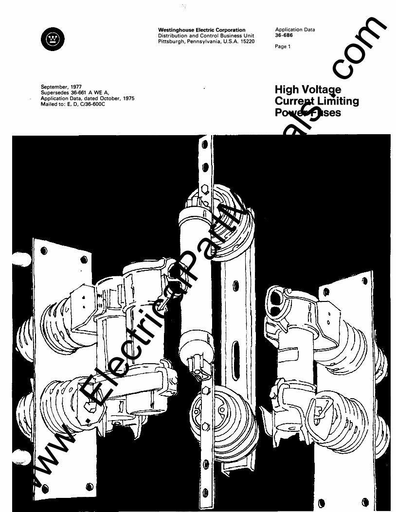
High Voltage Current Limiting Power Fuses
www . El
ectric
alPar
tMan
uals
. com

Page 2
Table of Contents Introd uction General Information -Fuse types
Si lver-sand fuses Fatigue proof General purpose and back-up
Current Limiting Description Description of operation Forced current zero Arc voltages Threshold va lue
Fuse Selection Selection process
Voltage R ating Minimum al lowable value Maximum suggested value
Interrupting R ating Symmetrical rating Asymmetrical rating Three- phase KVA rating Asymmetry factor X/R ratio I nterrupting rating versus let-through 25 hertz derating factor Altitude derating factor Low current l imits
Conti n uous Cu rrent Rating Avai lable rati ngs E rati ngs C rati ngs Overloads Application ratio Fuses in enclosures Paral le l ing fuses Altitude derati ng factor
Coord i nation Melting characteristics Total clearing characteristics i2t val ues Time-current relationships Arcing time Proper coordination Safety zone Ambient adjustments Preloadi ng adjustments Para l leled fuse coordination
Application General purpose and back- up
Let-Through Cu rrent Let-through defin ition Influencing factors Let-through curves
2 2-3
3
3
3
4
4-7
7-8
8
9
Fuses and Lightning Arresters 9-10 Arc voltages Location of fuse Distribution arresters Station arresters Line arresters Machine protection arresters
Transformer Application 10- 11 Magnetizing or inrush current Overloads Appl ication ratio Suggested current ratings Applying back-up fuses
Potential T ransformer Application 11 -12 Selection process
Motor Protection 12-13 Protection requirements Fuse selection requirements Use of general purpose fuses Fuse selection aid
Repetitive Fau lts 13 Fuse with reclosing breakers
Appendix 1 -Transformer Application 13 -16
Fuse purpose Selection process Min imum current rating
Magnetizing or i nrush current Overloads Suggested current ratings Thermal protective equi pment Forced cooling
Maximum current rating Transformer heat curves Symmetrical faults Unsymmetrical faults Line versus winding current Coordi nation diagrams
Introduction The Westinghouse selection of power fuses offers such diverse characteristics that a lmost any kind of appl ication, within the pract i -ca l ra nge of such i nterrupting devices, may be satisfied. These diverse characteristics are obtained, in part, by the production of both expulsion and current l imiting power fuses. Expulsion and current l imiting fuses provide the diverse characteristics by employing different areas of fuse technology. Along with diverse characteristics, however, the difference i n technology also requires that different q uestions be answered when applyi ng the two different types of fuses. For this reason and in an attempt to avoid confusion this appl ication data pertains only"to current l imiting fuses. See a ppl ication data 36- 664 for expulsion fuses.
General Information Westinghouse provides a wide range of high voltage current l imiting fuses. The CLE is a general purpose fuse which may be used to protect power transformers or in conj u nction with a disconnect switch. It is avai lable with either a disconnect or non-disconn ect mounting . An outdoor version of this fuse is cal led the CLO and it is used wi th a disconnect mounting.
Distribution transformer protection i s provided by the CL T and CX fuse l i nes. The CLT and ex may be employed in a submersible dry well in pad mounted transformers, with the EFD switch or with conventional discon necting or non-disconnecting type mou ntings. Other members of the CLT family i n cl ude the CL TB, CLTO a n d the C LTX. Each of these fuses has been designed for specific applications. The CLTB is mounted in the bushing of a poletop transformer, the C LTO is mounted under oil, and the C LT is used with the T-Tap vacuum switch. The newest member of the distribution fuse family is the ex. In addition to the features provided by the CLT it adds mechan ical i nterchangeability with other fuses on the market.
Poletop transformers may also be protected with the FDL which is a current l i miting fuse designed to be used in series with a l i n k and mounted in a standard Westinghouse cutout mou nting. The CL TX, or Pro-TEK, is a current l imiting fuse which is easily placed between the l ine and the transformer bushing by mounting it directly on top of the transformer bushing or on a cutout mou nting.
The last of the basic high voltage current l imiting fuse categories is the CLS. It is used to protect high voltage motor starter circuits.
Current l imiting fuses are also referred to as silver san d fuses. This reference comes from the fact that the basic design of the fuse incorporates a silver element which is placed in a sand medi um. Very basically, the si lver is a current responsive element and the sand
www . El
ectric
alPar
tMan
uals
. com
a cool ing and a bsorbing agent for the vaporized silver when a fault occurs. I nterruption of the circuit is quiet and completely selfcontained.
All Westinghouse current limiting fuses are designed to be fatigue proof. By this it is meant that the element of a properly appl ied fuse wil l not age, become brittle or deteriorate u nder the most severe duty cycling. This Westinghouse patented feature is provided by bending or spira l l ing the elements and thus a l lowing them to absorb the contractions and expansions created by the heating and cool ing associated with severe cycl ing.
I t is very important to realize that there are two basic types of current limiting power fuses. They are the general purpose, function class 'g', fuse which protects against both h igh and low values of fault current and the back- up, function class 'A', fuse which on ly protects agai nst fault currents to a specified minimum value. The general purpose fuse should clear any val ue of fault current that wil l cause the element to melt but may be damaged by severe overloading. A fuse which would not be damaged by overloading might be termed self- protecting although standards do not define such terminologies. However, a fuse meeting the self-protecting requirements as stated above, may stil l be damaged if the element is melted or broken and then full load current or less is appl ied to the fuse. Back- up fuses, on the other hand, are only designed to protect against h igh fault currents and must be used in series with another protection device which protects against the lower values of fault current.
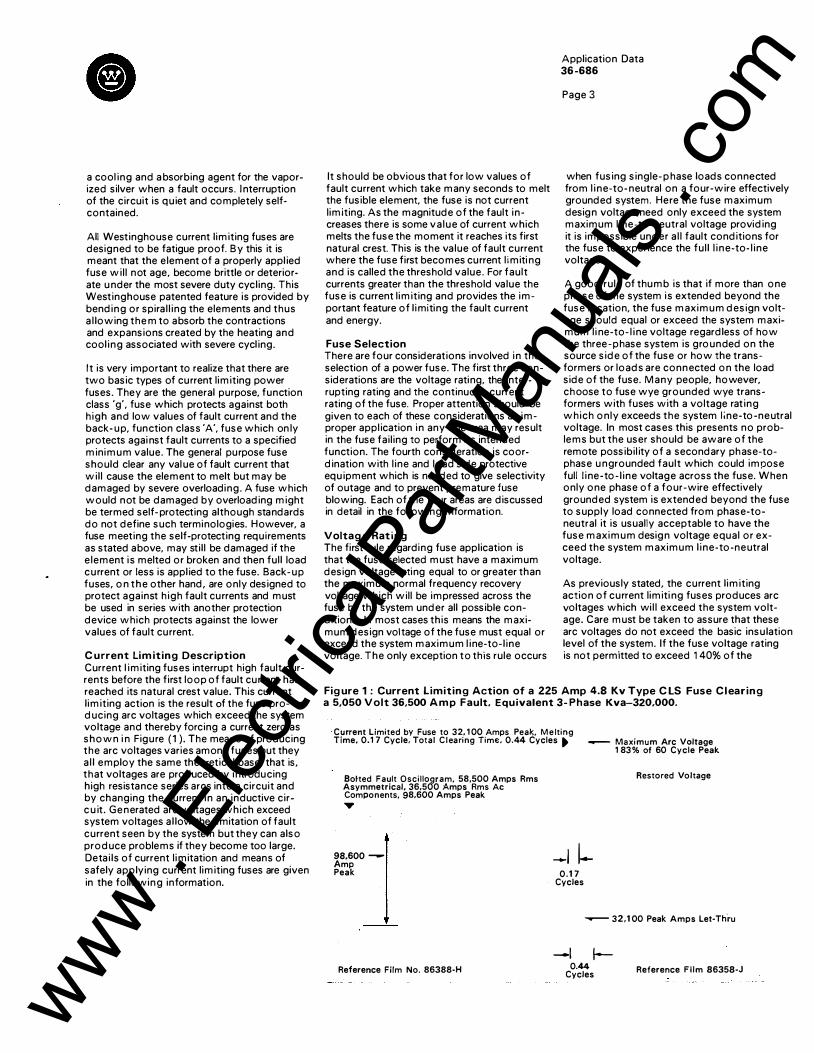
C urrent Lim iting Description Current l imiting fuses interrupt high fault currents before the first loop of fault current has reached its natural crest value. This current limiting action is the result of the fuse producing arc voltages which exceed the system voltage and thereby forcing a current zero as shown i n Figure (1 ). The means of producing the arc voltages varies among fuses but they a l l employ the same theoretical base, that is, that voltages are produced by introducing high resistance series arcs into a circuit and by changing the current in an inductive circ u it. Generated arc voltages which exceed system voltages a l low the l imitation of fault current seen by the system but they can also produce problems if they become too large. Detai ls of current l imitation and means of safely applying current limiting fuses are given in the following information.
It should be obvious that for low values of fault current which take many seconds to melt the fusible element, the fuse is not current limiting. As the magnitude of the fault increases there is some va lue of current which melts the fuse the moment it reaches its first natural crest. This is the value of fault current where the fuse first becomes current l imiti ng and is called the threshold value. For fault currents greater than the threshold value the fuse is current limiting and provides the important feature of l imiting the fault current and energy.
Fuse Selection There are four considerations involved in the selection of a power fuse. The first three considerations are the voltage rating, the interrupting rating and the continuous current rating of the fuse. Proper attention should be given to each of these considerations as improper appl ication in any one area may result in the fuse fail ing to perform its intended function. The fourth consideration is coordination with l ine and load side protective equ ipment which is needed to give selectivity of outage and to prevent premature fuse blowing. Each of the four areas are discussed in detail in the following information.
Voltage Rating The first rule regarding fuse application is that the fuse selected must have a maximum design voltage rating equal to or greater than the maximum normal frequency recovery voltage which will be impressed across the fuse by the system under all possible conditions. In most cases this means the maximum design voltage of the fuse must equal or exceed the system maximum l ine-to- l ine voltage. The only exception to this rule occurs
Application Data 36-686
Page 3
when fusing single- p hase loads connected from l ine-to- neutral on a four-wire effectively grounded system. Here the fuse maximum design voltage need only exceed the system maximum l ine-to-neutral voltage providing it is impossible under a l l fault conditions for the fuse to experience the ful l l ine-to- l ine voltage.
A good rule of thumb is that if more than one phase of the system is extended beyond the fuse location, the fuse maximum design voltage should equal or exceed the system maximum l i ne-to- l ine voltage regardless of how the three-phase system is grounded on the source side of the fuse or how the transformers or loads are connected on the load side of the fuse. Many people, however, choose to fuse wye grounded wye transformers with fuses with a voltage rat ing which only exceeds the system J ;ne-to-neutral voltage. In most cases this presents no problems but the user should be aware of the remote possibil ity of a secondary phase-tophase u ngrounded fault which could impose full l ine-to- l ine voltage across the fuse. When only one phase of a four-wire effectively grounded system is extended beyond the fuse to supply load connected from phase-toneutral it is usually acceptable to have the fuse maximum design voltage equal or exceed the system maximum l ine-to-neutral voltage.
As previously stated, the current limiting action of current limiti ng fuses produces arc voltages which wi l l exceed the system voltage. Care must be taken to assure that these arc voltages do not exceed the basic insulation level of the system. If the fuse voltage rating is not permitted to exceed 140% of the
Figure 1 : Current Limiting Action of a 225 Amp 4.8 Kv Type C LS Fuse Clearing a 5,050 Volt 36,500 A m p Fault. Equivalent 3- Phase Kva-320,000.
Current Limited by Fuse to 32, 1 00 Amps Peak, M e lting Time, 0.1 7 Cycle, Total Clearing Time, 0.44 Cycles . .....- Maximum Arc Voltage
1 83% of 60 Cycle Peak
Botted Fault Oscil logram, 58,500 Amps Rms Asymmetrical, 36,500 Amps Rms Ac Components, 98,600 Amps Peak ...,
98,600 -Amp Peak
Reference Film No. 86388-H
-l l-0.1 7
Cycles
Restored Vo ltage
._-- 32,1 00 Peak Amps Let-Th.ru
-1 1-
0.44 Cycles Reference Fi lm 86358-J
www . El
ectric
alPar
tMan
uals
. com
Page 4
system voltage, the arc voltages wil l generally not create problems. This 1 40% l imit on the voltage rating over system voltage does not restrict the use of a hig her rated fuse if the system has a high enough B I L to withstand the short time application of the arc voltage. Westinghouse current l imiting fuses are designed so that the arc voltage peak at rated interrupting current is less than three times that of the nominal voltage rating. If the system can withstand this peak, the higher rated fuse may be used.
Probably the most common problem created by high arc voltages is the sparking over of l ightn ing arresters. As this is a common problem, it is d iscussed in detail in the section ' Fuses and Lightning Arresters'.
It should be remembered that in most cases the fuse voltage rating should not exceed the system voltage by more than 40% and u nder no circumstances may the system voltage exceed the maximum design voltage rating of the fuse.
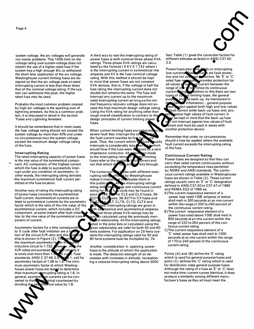
I nterrupting R ating The rated interrupting capacity of power fuses is the rms value of the symmetrical component, AC component, of the highest current which the fuse is able to successfully interrupt under any condition of asymmetry. I n other words, the i nterrupting rating denotes
-the maximum symmetrical fault current permitted at the fuse location.
Another way of rating the interrupting rating of power fuses concerns the asymmetrical fault current. Asymmetrical currents are related to symmetrical currents by the asymmetry factor which is the ratio of the rms value of the asymmetrical current, which includes a D C component, at some instant after fault initiation to the rms value of the symmetrical component of current.
Asymmetry factors for a time corresponding to % cycle after fault in itiation are a func-tion of the circuit X/R ratio and this relationship is shown in Figure (2) . Theoretically, the maximum asymmetry factor in a purely inductive circuit is 1 .732; however, with the X/R ratios encountered in power circuits it is rarely ever more than 1 .6 at % cycle. Fuse standards, ANSI C 37.46-2.5, Table 1 , call for asymmetry factors of 1 .56 to 1 .6. The min imum asymmetry factor at which Westinghouse power fuses are tested to determine their maximum interrupting rating is 1 .6. I n general, asymmetrical currents can b e converted to their symmetrical counterpart by dividing the asymmetrical value by 1 .6.
A third way to rate the interrupting rating of power fuses is with nominal three- phase KVA ratings. Three-phase KVA ratings are calculated by the formula I X KV X 1 .732 where I is the interrupting current i n symmetrical rms amperes and KV is the fuse nominal voltage rating . With this method it should be kept in mind that power fuses are not constant KVA devices, that is, if the voltage is half the fuse rating the i nterrupting current does not double but remains the same. The fuse wil l interrupt any current up to the maximum rated interrupting current as long as the normal frequency recovery voltage does not exceed the fuse maximum design voltage rating . Using the KVA rating for anything other than rough overall classification is contrary to the design principles of current l imit ing power fuses.
When current l imiting fuses are subjected to a severe fault they interrupt the circuit before the fault current reaches its first half cycle peak. Thus, the current which the fuse actually interru pts is considerably less than that which would flow if the fuse were replaced by a zero i m pedance cond uctor. All references made to the interrupting rating of current l imiting fuses refer to the avai lable fault current and not that which the fuse actually lets through.
The n umerous fuse styles with d ifferent interrupting ratings offered by Westing house makes it i mpractical to tabulate them in this publication . All the interrupting rat ings along with the voltage and continuous current rating for each fuse style may be found i n price list 36-621 for C L E and C L O fuses, 36-622 for C LS fuses, 36-627 for CX fuses and 36-623 for CLT, CL TB, CLTO, C L TX an d F D L fuses. I nterrupting ratings are given in both symmetrical and asymmetrical amperes. Nominal three-phase KVA ratings may be quickly calculated using the previously mentioned relationship. All the interrupting ratings listed in the price lists or calculated using the given relationship are valid for both 50 and 60 hertz systems. For application on 25 hertz systems the i nterrupting ratings val id for 50 and 60 hertz systems must be multiplied by .74.
Another consideration in applyin g power fuses is the altitude at which the application is made. The dielectric strength of air decreases with increases in altitude, necessitating a reduced interrupting rating above 3000
feet. Table ( 1 ) g ives the correction factors for d ifferent altitudes as listed in ANSI C37.40-2.3.
Power fuses also have l imits on interrupting low currents. These devices are fault protective and not overload protective. No 'E' or ' C' rated fuse necessarily provides protection for all values of overload current between the range of one to two times its continuous current rating. In addition to this there are two types of current limiting fuses, the general purpose and the back-up. As mentioned in the 'General Information' , general purpose fuses protect against both high and low values of fault current while back- u p fuses only protect against high values of fault current. It must be kept in mind that the back- up fuse will not interrupt against low val ues of fault current and must be used in series with another protection device.
Remember that under no circumstances should a fuse be applied where the avai lable fault current exceeds the interrupting rating of the fuse.
Continuous Cu rrent R ating Power fuses are designed so that they can carry their rated current contin uously without exceeding the temperature rises permitted by N EMA and ANSI standards. The contin uous current ratings avai lable in Westinghouse fuses are shown in Table (2) . These current ratings usually carry an 'E' or ·c· designation defined in ANSI C37.40 to C37.47 of 1 969 and N EMA SG2 of 1 969 as: A) The current-responsive element of a
power fuse rated 1 OOE amperes or below shall melt in 300 seconds at an rms current within the range of 200 to·240 percent of the continuous current rating.
B )The current -responsive element of a power fuse rated above 1 OOE shall melt in 600 seconds at an rms current within the range of 220 to 264 percent of the continous current rating.
C) The current-responsive element of a ·c· rated power fuse shall melt in 1 000 seconds at an rms current within the ran ge of 1 70 to 240 percent of the continuous current rating.
Points (A) and (B) define the 'E' rating w hich is used for general purpose fuses and point ( C) defines the ' C' rating which is used for distribution class general purpose fuses. Although the rating of a fuse as 'E' or ' C' does not make time-current curves identical, it does produce a simi larity among d ifferent manufacturer's fuses as they a l l must meet the
www . El
ectric
alPar
tMan
uals
. com
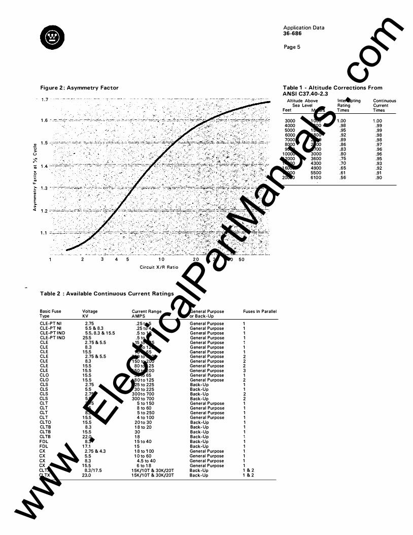
Figure 2 : Asymmetry Factor
1 .7
1 .6
Ql 1 . 5 _;_;.;;� .;.=�·'·'"' C3 > u
�
1 . 1
2 3 4 5 1 0
Circuit X/R Ratio
Table 2 : Avai lable Continuous Current Ratings
Basic Fuse Voltage Current Range Type KV AMPS
CLE-PT NI 2.75 .25 to 5 CLE-PT Nl 5.5 & 8.3 .25 to 4 CLE-PT I N D 5.5, 8.3 & 1 5.5 .5 to 1 0 CLE-PT I N D 25.5 .5 to 1 CLE 2.75 & 5.5 15 to 225 CLE 8.3 1 5 to 1 25 CLE 1 5.5 1 5 to 65 CLE 2.75 & 5.5 250 to 750 CLE 8.3 1 50 to 200 CLE 1 5.5 80 to 1 25 CLE 1 5.5 1 50 to 200 CLO 1 5.5 30 to 65 CLO 1 5.5 80 to 1 25 CLS 2.75 25 to 225 CLS 5.5 30 to 225 CLS 2.75 300to 700 CLS 5.5 300 to 700 CLT 2.75 5 to 1 50 CLT 5.5 8 to 60 CLT 8.3 5 to 250 CLT 1 5.5 4 to 1 00 CLTO 1 5.5 20 to 30 CLTB 8.3 1 8 to 20 CLTB 1 5.5 30 CLTB 22.0 1 8 FDL 8.3 1 5 to 40 FDL 1 7.1 1 5 ex 2.75 & 4.3 1 8 to 1 00 ex 5.5 1 0 to 60 ex 8.3 4.5 to 40 ex 1 5.5 6 to 1 8 CLTX 8.3/1 7.5 1 5K/1 OT & 30K/20T CLTX 23.0 1 5K/1 OT & 30K/20T
2 0 3 0 40 50
General Purpose Fuses In Parallel or Back-Up
G eneral Purpose 1 General Purpose 1 General Purpose 1 General Purpose 1 General Purpose 1 G eneral Purpose 1 General Purpose 1 General Purpose 2 General Purpose 2 General Purpose 2 General Purpose 3 General Purpose 1 General Purpose 2 Back- Up 1 Back-Up 1 Back- Up 2 Back-Up 2 General Purpose 1 General Purpose 1 General Purpose 1 General Purpose 1 Back-Up 1 Back- Up 1 Back-Up 1 Back-Up 1 Back-Up 1 Back-Up 1 General Purpose 1 General Purpose 1 General Purpose 1 General Purpose 1 Back-Up 1 & 2 Back-Up 1 & 2
Application Data 36-686
Page 5
Table 1 - Altitude Corrections From ANSI C37.40-2.3
Altitude Above Sea Level
Feet Meters
3000 4000 5000 6000 7000 8000 9000
1 0000 1 2000 1 4000 1 6000 1 8000 20000
1 000 1 200 1 500 1 800 21 00 2400 2700 3000 3600 4300 4900 5500 6100
Interrupting Rating Times
1 .00 .98 .95 .92 .89 .86 .83 .80 .75 .70 .65 .61 .56
Continuous Current Times
1 .00 .99 .99 .98 .98 .97 .96 .96 .95 .93 .92 .91 .90
www . El
ectric
alPar
tMan
uals
. com
Page 6
Figure 3 : Overload Characteristics 3A
Hours
1 . 5
Seco n d s
1 000
600
300
3 8
Hours
2
600
300 "·"-�'-'·'·"":o::: .. ·
' ,,
-····��··· -· ·'·'f
' ' \
200
. ' ·=-·'i��;;�;:;:;�ffi��::c:..... _ •. ��':-.:::. -�--
1 00 1 00
2 3 4
X 1 00% of Fuse R a t i n g
curves ., .\
2
\ .\ . . .
3
X 1 00% of Fuse Rat ing
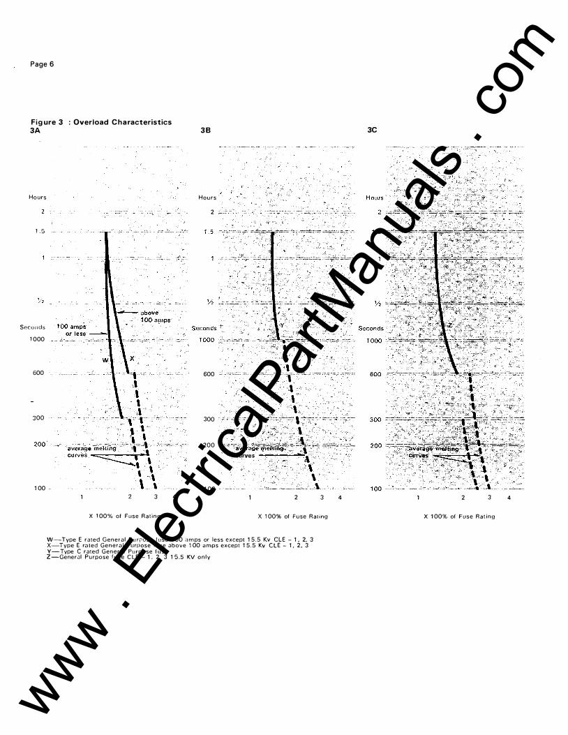
W-Type E rated G en e ral Pu rrose l use 1 00 a m ps or less except 1 5 .5 Kv CLE � 1 , 2, 3 X-Type E ru ted Generul Purpose fuse above 1 00 amps except 1 5 . 5 Kv C L E - 1 , 2, 3 Y-Type C rated General Purpose f u se Z-General Pu rpose fuse C L E - 1 . 2. 3 1 5 .5 KV o n l y
4
3C
2 3 4
X 1 00% of Fuse Ra t in g
www . El
ectric
alPar
tMan
uals
. com
e
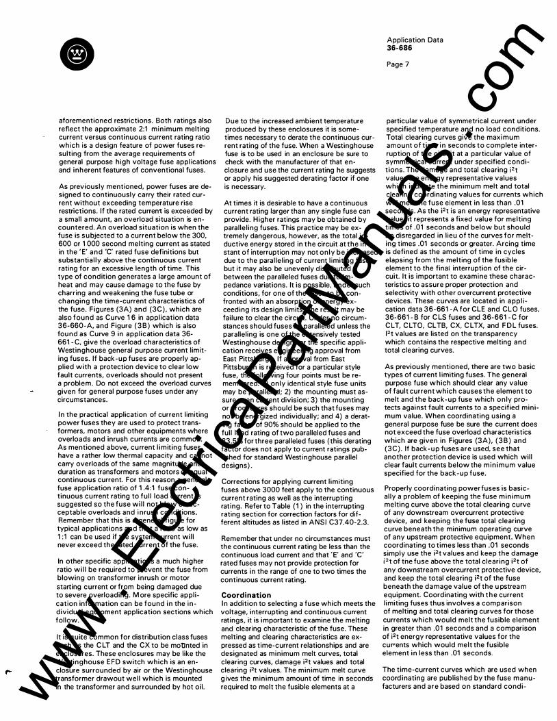
aforementioned restrictions. Both ratings also reflect the approximate 2:1 minimum melting current versus continuous current rating ratio which is a design feature of power fuses resulting from the average requirements of general purpose high voltage fuse appl ications and inherent features of conventional fuses.
As previously mentioned, power fuses are designed to continuously carry their rated current without exceeding temperature rise restrictions. If the rated current is exceeded by a small a mount, an overload situation is encountered. An overload situation is when the fuse is subjected to a current below the 300, 600 or 1 000 second melting current as stated in the ' E' and 'C' rated fuse definitions but substantial ly above the continuous current rating for an excessive length of time. This type of condition generates a large amount of heat and may cause damage to the fuse by charring and weakening the fuse tube or changing the time-current characteristics of the fuse. Figures (3A) and (3C), which are also found as Curve 1 6 in application data 36-660-A, and Figure ( 3 B ) which is also found as Curve 9 in application data 36-661 - C, give the overload characteristics of Westinghouse general purpose current limiting fuses. If back-up fuses are properly applied with a protection device to clear low fault currents, overloads should not present a problem. Do not exceed the overload curves given for general purpose fuses under any circumstances.
In the practical application of current limiting power fuses they are used to protect transformers, motors and other equipments where overloads and inrush currents are common. As mentioned above, current l imiting fuses have a rather low thermal capacity and cannot carry overloads of the same magnitude and duration as transformers and motors of equal continuous current. For this reason a general fuse appl ication ratio of 1 .4:1 fuse continuous current rating to ful l load current is suggested so the fuse wil l not blow on acceptable overloads and i nrush conditions. Remember that this is a general figure for typical appl ications and that a ratio as low as 1 :1 can be used if the system current will never exceed the rated current of the fuse.
In other specific applications a much higher ratio wil l be required to prevent the fuse from blowing on transformer inrush or motor starting current or from being damaged due to severe overloading. M ore specific application information can be found in the individual equipment application sections which follow.
It is q uite common for distribution class fuses such as the C LT and the CX to be moUnted in enclosures. These enclosures may be like the Westinghouse EFD switch which is an enclosure surrounded by air or the Westinghouse transformer drawout well which is mounted in the transformer and surrounded by hot oil.
Due to the increased ambient temperature produced by these enclosures it is sometimes necessary to derate the continuous current rating of the fuse. When a Westinghouse fuse is to be used in an enclosure be sure to check with the manufacturer of that enclosure and use the current rating he suggests or apply his suggested derating factor if one is necessary.
At times it is desirable to have a continuous current rating larger than any single fuse can provide. Higher ratings may be obtained by paralleling fuses. This practice may be extremely dangerous, however, as the total inductive energy stored in the circuit at the instant of interruption may not only be increased due to the paralleling of current l imiting fuses, but it may also be unevenly distributed between the paralleled fuses due to impedance variations. It is possible, under such conditions, for one of the fuses to be confronted with an absorption of energy exceeding its design limits. The result may be fai lure to clear the circuit. Under no circumstances should fuses be paralleled unless the paralleling is one of the extensively tested Westinghouse designs or the specific application receives engineering approval from East Pittsburgh. If approval from East Pittsburgh is received for a particular style fuse, the following four points must be remembered: 1 ) only identical style fuse units may be paralleled; 2) the mounting must assure even current division; 3) the mounting or procedures should be such that fuses may not be energized individually; and 4) a derating factor of 90% should be applied to the full load rating of two paralleled fuses and 83.5% for three paralleled fuses (this derating factor does not apply to current ratings published for standard Westinghouse parallel designs) .
Corrections for applying current l imiting fuses above 3000 feet apply to the continuous current rating as well as the interrupting rating. Refer to Table (1 ) in the interrupting rating section for correction factors for different altitudes as listed in ANSI C37.40-2.3.
Remember that under no circumstances must the continuous current rating be less than the continuous load current and that ' E' and 'C' rated fuses may not provide protection for currents in the range of one to two times the continuous current rating.
Coordination In addition to selecting a fuse which meets the voltage, interrupting and continuous current ratings, it is important to examine the melting and clearing characteristic of the fuse. These melting and clearing characteristics are expressed as time-current relationships and are designated as minimum melt curves, total clearing curves, damage i2t values and total clearing i2t values. The minimum melt curve g ives the minimum amount of time in seconds required to melt the fusible elements at a
Application Data 36-686
Page 7
particular value of symmetrical current under specified temperature and no load conditions. Total clearing curves give the maxi mum amount of t ime i n seconds to complete interruption of the circuit at a particular value of symmetrical current under specified conditions. The damage and total clearing i2t values are energy representative values which indicate the minimum melt and total clearing coordinating values for currents which will melt the fuse element in less than .01 seconds. As the i2t is an energy representative value, it represents a fixed value for melting times of .01 seconds and below but should be disregarded in lieu of the curves for melting times .01 seconds or greater. Arcing time is defined as the amount of time in cycles elapsing from the melting of the fusible element to the final interruption of the cir-cuit. It is important to examine these characteristics to assure proper protection and selectivity with other overcurrent protective devices. These curves are located in appl i cation data 36-661 -A for CLE and CLO fuses, 36-661 - B for C LS fuses and 36-661 - C for C LT, C LTO, CLTB, CX, C LTX, and F D L fuses. 12t values are listed on the transparency which contains the respective melting and total clearing curves.
As previously mentioned, there are two basic types of current l imiting fuses. The general purpose fuse w hich should clear any value of fault current which causes the element to melt and the back-up fuse which only protects against fault currents to a specified minimum value. When coordinating using a general purpose fuse be sure the current does not exceed the fuse overload characteristics which are given in Figures (3A), ( 3 B ) and (3C) . If back-up fuses are used, see that another protection device is used which will clear fault currents below the min imum value specified for the back-up fuse.
Properly coordinating power fuses is basically a problem of keeping the fuse minimum melting curve above the total clearing curve of any downstream overcurrent protective device, and keeping the fuse total clearing curve beneath the minimum operating curve of any upstream protective equipment. When coordinating to times less than .01 seconds simply use the i2t values and keep the damage i2t of the fuse above the total clearing i2t of any downstream overcurrent protective device, and keep the total clearing i2t of the fuse beneath the damage value of the u pstrea m equipment. Coordinating with t h e current l imiting fuses thus involves a comparison of melting and total clearing curves for those currents which would melt the fusible element in greater than .01 seconds and a comparison of i2t energy representative values for the cur•ents which would melt the fusible element in less than .01 seconds.
The time-current curves which are used when coord inating are published by the fuse manufacturers and are based on standard condi-www .
Elec
tricalP
artM
anua
ls . c
om

Page 8
Figure 4 : Effect of Am bient Temperature On Melting Curve
1 30
1 1 0������� 1 00 �
90 ����::��=��.· =�=�����,���'�
-30 -20 -10 0 1 0 20 30 40 50 60
Temperature in Degree Centigrad e
tions which do not al low for such variables as preloading, ambient temperature and manufacturing tolerances. For this reason it is re commended that a safety zone be used when coord inating power fuses so proper coordination is maintained even when there are shifts in the curves due to changes in the above-mentioned variables. There are two approaches used to achieve this safety zone and both produce similar results. One approach employs a 25 percent safety zone in time for a given value of current and the other uses a 1 0 percent safety zone in current for a -given value of time. Westinghouse uses the second method as it a l lows the safety band to be published on the left hand side of all the time-current curves. Coordination is then achieved by overlaying curves and shifting one by the width of the published safety zone.
If desired or if unusual conditions exist, shifts in the time-current curve due to ambient temperature and preloading may be examined individually. Westinghouse time-current characteristics are derived from tests on fuses in an ambient temperature of 25 degrees C and no in itial loading as specified in ANSI C37.46. Fuses subjected to conditions other than the above will experience shifts in the time-current curves. Figure (4) gives the adjusting factor for changes in ambient temperature and Figure (5) the adjusting factor for pre loaded fuses. These adjusting factors are val id only for Westinghouse power fuses.
When a paralleled fuse combination is to be coordinated with other devices, the melting and clearing curves for the combination must
Figure 5 : P reloading Adjustment Factor For Power Fuses
0 50 1 00 1 50 200
Load Current in Percent of Fuse Ampere Rat ing
2 50
p --7 Formula for Above Curves:
F = 1 -( P /PM)2 PM = Percent of M i nimum Load Current Causing
Melting which is 200% for Fuses 1 00 Amps and Less - "E" Rated 220% for Fuses Above 1 00 Amps - " E " Rated 1 70% for Fuses which are ·c· Rated
For permissible duration of Load Currents above 1 00% see Figure 3.
be adjusted. The minimum melting and total clearing curves for the two fuses in parallel should be such that the combination curve, for a given time, has a current value of 1 80% of the current value of the single fuse. For currents which melt the fusible element in less than .01 seconds the two fuses in parallel would have a damage i2t value four times that of the single fuse and a total clearing i2t 2.5 times that of the single fuse.
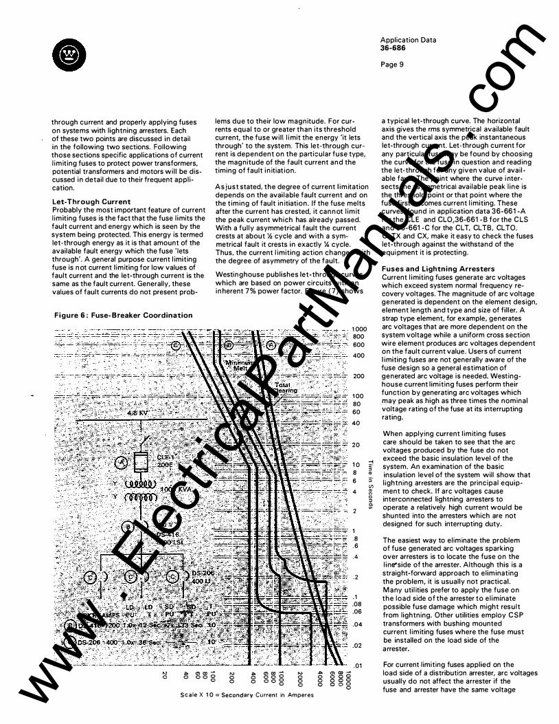
Figure (6) gives an example of a properly coordinated fuse application. The figure shows a general purpose CLE fuse protecting the primary of a 1 000 KVA transformer with Westinghouse type DS low voltage air circuit breakers protecting the secondary equipments.
Coordination with reclosing circuit breakers may be performed with the aid of the coordination chart found as Curve 23 in application data 36-660-A. This curve is explained in the repetitive faults section of this application data.
Application When applying current limiting power fuses there are some points to be kept in mind in addition to the basics of voltage rating, interrupting rating, continuous current rating and coordination. One of these points concerns the two types of current limiting fuses, general purpose and back-up. A general purpose fuse is a complete protection device but the backup fuse m ust be used in series with another protection device so it will not be called upon to interrupt currents that are below its specified minimum interrupting rating. Examples of a properly applied back-up current l imiting fuse are the CLS where the fuse is used in series with a motor starter to protect it from fault currents which exceed the starter rating and the F D L which is used in series with a protective l ink to provide a much higher i nterrupting rating than the l ink alone could provide.
Other points to consider when applying current limiting fuses include those of let-www .
Elec
tricalP
artM
anua
ls . c
om
through current and properly applying fuses on systems with lightning arresters. Each of these two points are discussed in detail in the following two sections. Following those sections specific applications of current l imiting fuses to protect power transformers, potential transformers and motors wil l be discussed in detail due to their frequent application.
Let-Through Current Probably the most important feature of current l imiting fuses is the fact that the fuse l imits the fault current and energy which is seen by the system being protected. This energy is termed let-through energy as it is that amount of the available fault energy which the fuse ' lets through'. A general purpose current l imiting fuse is n ot current l imiting for low values of fault current and the let-through current is the same as the fault current. Generally, these values of fault currents do not present prob-
Figure 6 : Fuse- Breaker Coordination
lems due to their low magnitude. For currents equal to or greater than its threshold current, the fuse wil l l i mit the energy 'it lets through' to the system. This let-through current is dependent on the particular fuse type, the magnitude of the fault current and the timing of fault i n itiat ion.
As just stated, the degree of current l imitation depends on the avai lable fault current and on the t iming of fault in itiation. If the fuse melts after the current has crested, it cannot l imit the peak current which has already passed. With a ful ly asymmetrical fault the current crests at about Y.z cycle and with a symmetrical fault it crests in exactly Y., cycle. Thus. the current l imiting action changes with the degree of asymmetry of the fault.
Westinghouse publishes let-through curves which are based on power circuits with an in herent 7% power factor. Figure (7) shows
1 000 800
600
400
200
1 00
80
60
40
20
1 0
8
6
4
2
1
.8
.6
.4
.2
. 1 .08
.06
.04
.02
.01
-i 3' CD :;· C/) CD "' a :::l Q. en
J:�. en c:c � 0 0 0 g "'
0 � en co � 0 0 0 0 0 0 0 g
N 0 0 0
.s::. 0) (X) ..... 0 0 o o 0 0 o o o o o g 0
Sca le X 1 0 = Secondary Current in Amperes
Application Data 36-686
Page 9
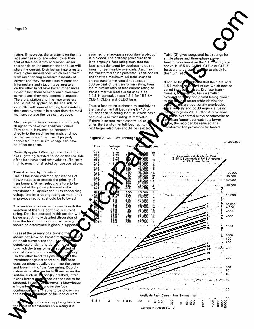
a typical let-through curve. The horizontal axis gives the rms symmetrical available fault and the vertical axis the peak instantaneous let-through current. Let-through current for any particular fuse may be found by choosing the curve for the fuse in question and reading the let-through for any given value of avail able fault. The point where the curve i ntersects the asymmetrical available peak l ine is the threshold point or that point where the fuse first becomes current l imiting. These curves, found in application data 36-661 -A for the CLE and CL0,36-661 - B for the C LS and 36-661 -C for the CLT. CL TB, CL TO. CL TX and CX, make it easy to check the fuses let-through against the withstand of the equi pment it is protecting.
Fuses and Lightning Arresters Current l imiting fuses generate arc voltages which exceed system normal frequency recovery voltages. The magnitude of arc voltage generated is dependent on the element design, element length and type and size of fil ler. A strap type element, for example, generates arc voltages that are more dependent on the system voltage while a uniform cross section wire element produces arc voltages dependent on the fault current value. Users of current l imiting fuses are not generally aware of the fuse design so a general estimation of generated arc voltage is needed. Westinghouse current l imiting fuses perform their function by generating arc voltages which may peak as high as three times the nominal voltage rating of the fuse at its interrupting rating.
When applying current l imiting fuses care should be taken to see that the arc voltages produced by the fuse do not exceed the basic insulation level of the system. An examination of the basic insulation level of the system will show that lightning arresters are the principal equipment to check. If arc voltages cause interconnected lightning arresters to operate a relatively high current would be shunted into the arresters which are not designed for such interrupting duty.
The easiest way to eliminate the problem of fuse generated arc voltages sparking over arresters is to locate the fuse on the l ine-side of the arrester. Although this is a straight-forward approach to eliminating the problem, it is usually not practical. Many util ities prefer to apply the fuse on the load side of the arrester to el iminate possible fuse damage which might result from lightning. Other utilities employ CSP transformers with bushing mounted current l imiting fuses where the fuse must be installed on the load side of the arrester.
For current limiting fuses applied on the load side of a distribution arrester, arc voltages usually do not affect the arrester if the fuse and arrester have the same voltage www .
Elec
tricalP
artM
anua
ls . c
om
Page 1 0
rati ng. If, however, the arrester is on the l ine side and has a voltage rating lower than that of the fuse, it may sparkover. Under this condition the arrester and the fuse wi l l share the current. Distribution type arresters have higher impedances which keep them from experiencing excessive amounts of current and they are not usually damaged. Intermediate and station type arresters on the other ha nd have lower impedances wh ich allow them to experience excessive currents and they may become damaged . Therefore, station and l ine type arresters should not be appl ied on the l ine side or in parallel with current l imiting fuses un less their sparkover value is greater than the maximum arc voltage the fuse ca n produce.
Machine protection arresters are purposely designed to have low sparkover values. They shou ld, however, be connected directly to the machine terminals and not on the l ine side of the fuse. If properly connected, the fuse arc voltage can have no effect on them.
Correctly appl ied Westinghouse distribution class l ightn ing arresters found on the l ine side of the fuse have sparkover values sufficiently high to remain unaffected by fuse operations.
Transformer Appl ication One of the more common applications of power fuses is to protect the primary of transformers. When selecting a fuse to be insta lled at the primary terminals of a transformer, a l l appl ication rules concerning voltage and interrupting rating as mentioned in previous sections, should be followed.
This section is concerned primarily with the selection of the fuse continuous current rating. Details d iscussed in this section wil l be general. A more detailed d iscussion of how the fuse continuous current rat ing should be determined is given in Appendix 1 .
Fuses at the primary of a transformer should not blow on transformer magnetizing or inrush current, nor should they blow or deteriorate u nder long duration overloads to which the transformer is subjected in normal service and in cases of emergency. On the other hand, they must protect the transformer against short circu its. These considerations usually determine the u pper and lower l imit of the fuse rating. Coord ination with other protective devices on the system, such as second�y breakers, often places further restrictions on the fuse to be selected. In general, however, a knowledge of transformer type al lows the fuse continuous current rating to be chosen on the basis of a m u ltiple of fu l l load current.
In the routine process of applying fuses on the basis of tra nsformer KVA rating it is
assumed that adequate secondary protection is provided. The ordinary procedure then is to employ a fuse rating such that the fuse is not damaged by overheating due to inrush or permissible overloads. Assu ming the transformer to be protected is self-cooled and that the maximum 1 .5 hour overload on the transformer would not exceed 200 percent of the transformer rating, then the min imum ratio of fuse current rating to transformer full load current should be 1 .4 : 1 in general, except 1 .5 : 1 for 1 5.5 KV CLE- 1 , CLE-2 and CLE-3 fuses.
Thus, a fuse rating is chosen by multiplying the transformer ful l load rating by 1 .4 or 1 .5 and then selecting the fuse which has a continuous current rating of that value. If there is no fuse rated exactly 1 .4 or 1 .5 times the transformer fu II load rating, the next larger rated fuse should be selected.
Figure 7 : CL T Let-Through Curves
Fuse Voltage Amps Rating Curve In KV
CLT 2 .75 5C 25,000 1 0 CLT 2.75 1 2 C 2 5,000 8 CLT 2.75 1 8C 25,000 7 C LT 2.75 25C 25,000 5 CLT 2.75 30C 25,000 4 CLT 5.5 8C 25,000 9 CLT 5.5 1 2C 25,000 8 CLT 5.5 18C 25,000 7 CLT 5.5 25C 25,000 5 CLT 8 .3 5C 25,000 1 0 CLT 8.3 8C 25,000 9 CLT 8.3 1 2 C 2 5,000 6 CLT 8.3 1 8C 25,000 7 CLT 8.3 25C 25,000 5 CLT 8.3 30C 25,000 4 CLT-1 2.75 90C 2 5,000 2 CLT-1 2.75 1 50C 25,000 1 CLT-1 5.5 30C 2 5,000 4 CLT-1 5.5 45C 25.000 4 CLT-1 5.5 60C 25,000 3 CLT-1 8.3 30C 2 5.000 4 CLT-1 8.3 45C 2 5,000 4 CLT-1 1 5.5 4C 25,000 1 6 CI:T-1 1 5.5 5 C 25,000 1 5 CLT-1 1 5.5 8C 25,000 1 4 CLT-1 1 5.5 1 2C 25.000 1 3 CLT-1 1 5.5 1 8C 25,000 1 1 CLT-1 1 4.4 30C 20,000 1 2
Table (3) gives suggested fuse ratings for single phase and three-phase power transformers based on the 1 .4 :1 ratio given above. I f 1 5.5 KV CLE-1 , CLE-2 or CLE-3 fuses are to be used, be sure to check for the 1 .5 : 1 ratio.
It should be remembered that the 1 .4 :1 and 1 .5 :1 ratios are general values which may be varied in specific cases. Dry type transformers, for instance, have a smaller overload capacity and permit fusing closer to the full load rating while distribution transformers are traditionally overloaded more severely and could require a fusing ratio as large as 2:t. Further, if provisions are made by thermal relays or otherwise to limit transformer overloads to a lower range, the ratio can be reduced. I f a transformer has provisions for forced
Asymmetrical Available Peak (2.55 X Symmetrical R M S Amperes}
at 7% Power Factor
., .. .. """ :; � .. ;?.
. .. . :I
. .. c ·C: .. .... .. � ,. 2 (") !:; ; ;?. :;· )> 3
"t) """' m ..
1 .000.000
1 00,000
80,000
60,000
40,000
20,000
1 0,000 8,000
... 6000
4000
2000
1 000
800
600
400
200
1 00
80
60
40
- 20
Available Fauit Current Rms Symmetrical
6 8 1 2 4 6 8 1 0 20 40 g g g 0 0 N
Current in Amperes X 1 0
0 0 0 0 0 0 0 0 v <D co o
0 0 0 N
1 0 0 0 0 0 0 0 0 0 0 0 0 0 v <0 00 0 www .
Elec
tricalP
artM
anua
ls . c
om
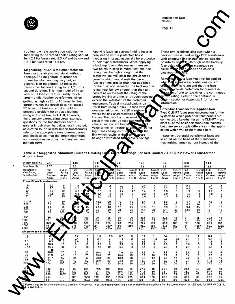
cooling, then the application ratio for the fuse rating to the forced cooled rating should be 1 .2:1 for fuses rated 8.3 KV and below and 1 .3 :1 for fuses rated 1 5.5 KV.
Magnetizing inrush is the other factor the fuse must be able to withstand without damage. The magnitude of inrush for power transformers may vary but, in general, is of magnitude 1 2 t imes the transformer ful l load rating for a 1 / 1 0 of a second duration. This magnitude of inrush versus full load current is usually much larger for distribution transformers, often getting as high as 25 to 40 times ful l load current. When the inrush does not exceed 1 2 times ful l load current it should not present a problem for a ny applications using a ratio as low as 1 :1 . If, however, there are any extenuating circumstances, questions, or the transformers have a greater inrush than the values just indicated, as is often found in distribution transformers, refer to the appropriate time-current curves and check to see that the inrush magnitude and duration never cross the fuses· m in imum melting curve.
Applying back-up current l imiting fuses in conjunction with a protective l ink is increasing in usage, especially for protection of pole type transformers. When applying a back- up fuse in this manner there are two points to keep in mind. First, the fuse rating must be high enough that the protective l ink wil l clear the circuit for all currents which wou ld melt the back- up fuse in a time greater than that published for the fuse; and secondly, the back-up fuse rating must be low enough that the fault current never exceeds the rating of the protective link and the let-through does not exceed the withstand of the protected equipment. Typical misapplications can result from using a back-up fuse with an oversize l ink or with a CSP transformer where the l ink characteristics are not known. The use of an oversized l ink can result in the back-up fuse attempting to clear a fault current below its publ ished value or the let-through of the back-up for high faults being insufficient to melt the l ink which results in the back-up fuse having to withstand ful l recovery voltage.
Application Data 36-686
Page 1 1
These two problems also exist when a back-up fuse is used with a CSP transformer with unknown l ink characteristics plus the possibil ity of the let-through of the back-up fuse being of sufficient magnitude to cause the l ink to explode and cause a catastrophic failure.
Remember that a fuse must not be applied where it can realize a continuous current greater than its rating and that the fuse may not provide protection for currents in the range of one to two times the continuous current rating. Refer to the continuous current section or Appendix 1 for further information . .
Potential Transformer Application Type C LE-PT fuses provide protection for the systems to which potential transformers are connected. Like other fuses the CLE- PT must meet al l of the basic selection requirements but there are a couple differences in the a ppl ication which will be mentioned here.
I nstrument potential transformer fuses are selected on the basis of the transformer magnetizing inrush current instead of the
Table 3 : Suggested M in i m u m Cu rrent Li m iting Fuse Current Ratings For Self-Cooled 2.4-1 5.5 KV Power Transformer Appl ications
System Nom. Kv 2.4 4.1 6 4.8 7.2 1 2.0 1 3.2 1 3.8 1 4.4 Fuse Max. Kv 2.75 5.5 5.5 8.3 1 5.5 1 5.5 1 5.5 1 5.5 Transformer Full Fuse(j) Full Fuse(j) Full Fuse(j) Full Fuse(j) Full Fuse(j) Full Fuse(j) Full Fuse(j) Ful l Fuse(j) KVA Rating Load Rating Load Rating Load Rating Load Rating Load Rating Load Rating Load Rating Load Rating Self-Cooled Current Amps Current Amps Current Amps C urrent Amps Current Amps Current Amps Current Amps Current Amps
Amps E or C Amps E or e Amps E or C Amps E or C Amps E or C Amps E or C Amps E or C Amp$ E or C Three Phase Transformers
9 2.2 5 1 .3 3 1 .1 3 0.7 3 0.4 1 0.4 1 0.4 1 0.4 1 1 5 3.6 5 2.1 3 1 .8 3 1 .2 3 0.7 1 0.7 1 0.6 1 0.6 1 30 7.2 1 2 4.2 8 3.6 5 2.4 4.5 1 .4 3 1 .3 3 1 .3 3 1 .2 3 45 1 0.8 1 5 6.2 1 0 5.4 8 3.6 5 2.2 4 2.0 3 1 .9 3 1 .8 3 75 1 8 25 1 0.4 1 5 9.0 1 5 6 1 0 3.6 6 3.3 5 3.1 5 3 5
1 1 2.5 27 40 1 5.6 25 1 3.6 20 9 1 5 5.4 8 5.0 8 4.7 8 4.5 8 1 50 36 50 20.8 30 1 8 25 1 2 1 8 7.2 1 0 6.6 1 0 6.2 1 0 6 1 0 225 54 75 31 .3 45 27.2 40 1 8 25 1 0.8 1 5 9.9 1 5 9.4 1 5 9 1 5 300 72 1 00 41 .6 60 36 50 24 35 1 4.4 25 1 3.1 20 1 2.5 1 8 1 2 1 8 500 1 20 200 69.4 1 00 60 1 00 40 60 24.1 40 21 .9 30 21 30 20 30
750 1 80 250 1 04 1 50 90 1 25 60 1 00 36.1 60 32.8 45 31 45 30.1 45 1 000 241 350X 1 40 200 1 20 200 80 1 25 48.1 75 43.7 65 42 60 40.1 60 1 500 360 600 208 300 1 80 250 1 20 200 72.2 1 00 65.6 1 00 62 1 00 60.1 1 00 2000 481 750 278 400X 241 350X 1 60 250 96.2 1 50 87.5 1 50 84 1 25X 80.2 1 25X 2500 600 . . . 346 600 301 450X 200 . . . 1 20 200X 1 09 1 75 1 04 1 75 1 00 1 50 Songle Phase Transformers
5 2.1 5 1 .2 3 1 .0 1 .5 0.7 3 0.4 1 o.4 1 0.4 1 0.4 1 1 0 4.2 1 2 2.4 5 2.1 3 1 .4 3 0.8 1 .5 0.8 1 .5 0.7 1 0.7 1 1 5 6.3 1 2 3.6 5 3.1 5 2.1 3 1 .3 3 1 .1 3 1 .1 3 1 .1 3 25 1 0.4 1 5 6 1 0 5.2 8 3.5 5 2.1 3 1 .9 3 1 .8 3 1 .7 3 37.5 1 5.6 25 9 1 5 7.8 1 2 5.2 8 3.1 5 2.8 4 2.7 4 2.6 4
50 20.8 30 1 2 20 1 0.4 1 5 7.0 1 0 4.2 8 3.8 8 3.6 8 3.5 5 75 3 1 .3 45 1 8 25 1 5.6 25 1 0.4 1 5 6.3 1 0 5.7 8 5.4 8 5.2 8
1 00 41 .7 60 24 40 20.8 30 1 3.9 20 8.3 1 2 7.6 1 2 7.2 1 2 6.9 1 0 1 67 70 1 00 40 50 35.0 50 23.2 40 1 3.9 20 1 2.7 1 8 1 2.1 1 8 1 1 .6 1 8 250 1 04 1 50 60 1 00 52.1 80 34.8 50 20.8 30 1 9.0 30 1 8.1 30 1 7.4 30
333 1 39 200 80 1 25 69.5 1 00 46.3 65 27.7 40 25.2 40 24.1 40 23.1 40 500 208 300 1 20 200 1 04 1 50 69.6 1 00 41 .6 60 38 60 36.2 60 34.7 60 667 278 400X 1 60 250 1 39 200 92.6 1 50 55.4 85 50.5 75 48.2 75 46.3 75 883 347 . . . 200 350X 1 73 250 1 1 5.5 200 69.4 1 00 63.5 1 00 60.4 85 57.8 85
1 250 521 . . . 300 450X 260 400X 1 74 250 1 04 1 75 95 1 50 90.6 1 50 86.8 1 25X
CD Fuse ratings are for the smallest fuse possible. Choose next largest rating if given rating is not available in selected fuse line. Be sure to check for 1 .5:1 ratio for 1 5.5 KV CLE- 1 , C LE-2 and CLE-3. www .
Elec
tricalP
artM
anua
ls . c
om
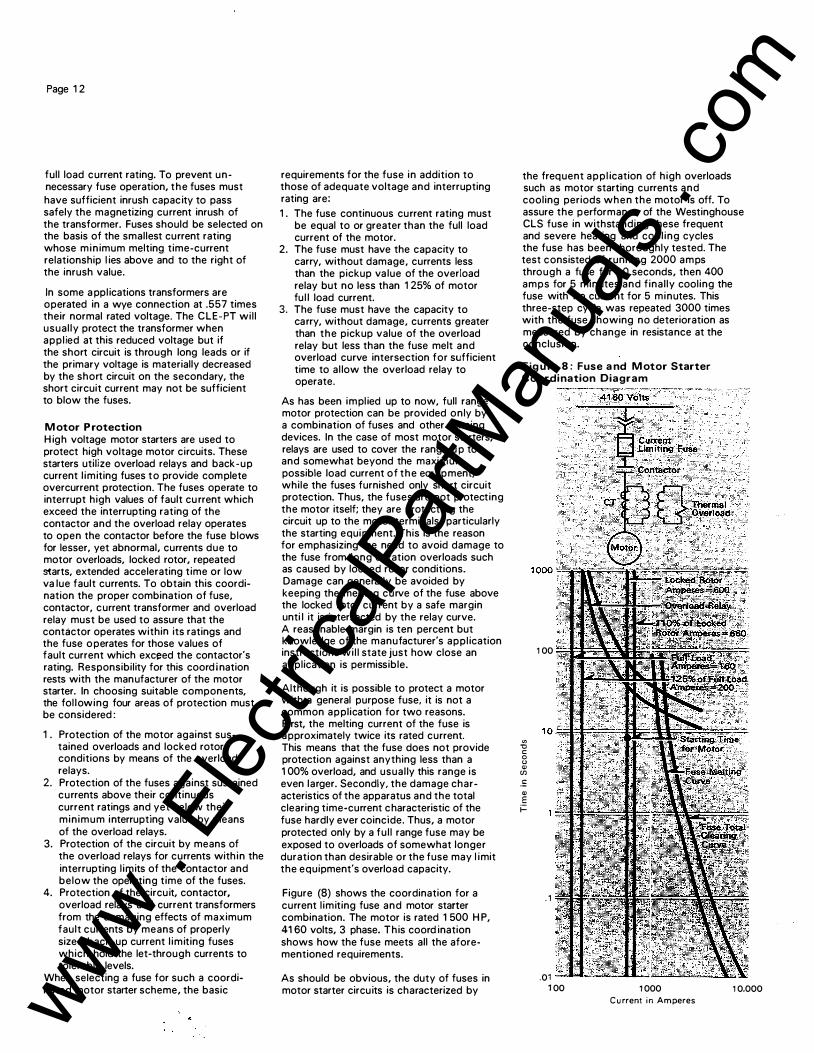
Page 1 2
full load current rating. To prevent unnecessary fuse operation, the fuses must have sufficient inrush capacity to pass safely the magnetizing current inrush of the transformer. Fuses should be selected on the basis of the smallest current rating whose min imum melting time-current relationship l ies above and to the right of the inrush value.
In some a ppl ications transformers are operated in a wye connection at .557 times their normal rated voltage. The CLE-PT wil l usual ly protect the transformer when appl ied at this reduced voltage but if the short circuit is through long leads or if the primary voltage is materially decreased by the short circuit on the secondary, the short circuit current may not be sufficient to blow the fuses.
M otor P rotection H igh voltage motor starters are used to protect high voltage motor circuits. These starters utilize overload relays and back-up current l imiting fuses to provide complete overcurrent protection. The fuses operate to interrupt high values of fault cu rrent which exceed the interrupting rating of the contactor and the overload relay operates to open the contactor before the fuse blows for lesser, yet abnormal, currents due to motor overloads, locked rotor, repeated starts, extended accelerating time or low va lue fault currents. To obtain this coordination the proper combination of fuse, contactor, current transformer and overload relay must be used to assure that the contactor operates within its ratings and the fuse operates for those values of fault current which exceed the contactor's rating. Responsibility for this coord i nation rests with the manufacturer of the motor starter. In choosing suitable components, the fol lowing four areas of protection must be considered :
1 . Protection of the motor against sustained overloads and locked rotor conditions by means of the overload relays.
2. Protection of the fuses against sustained currents above their continuous current ratings and yet below their min imum interrupting value by means of the overload relays.
3. Protection of the circuit by means of the overload relays for currents within the interrupting l imits of the contactor and below the operating time of the fuses.
4. Protection of the circuit, contactor, overload relays and current transformers from the damaging effects of maximum fault currents by means of properly sized back-up current l imiting fuses which hold the let-through currents to tolerable levels.
When selecting a fuse for such a coordinated motor starter scheme, the basic
requirements for the fuse in addition to those of adequate voltage and interrupting rating are: 1 . The fuse continuous current rating must
be equal to or greater than the full load current of the motor.
2. The fuse must have the capacity to carry, without damage, currents less than the pickup value of the overload relay but no less than 1 25% of motor fu l l load current.
3. The fuse must have the capacity to carry, without damage, currents greater than the pickup value of the overload relay but less than the fuse melt and overload curve intersection for sufficient time to al low the overload relay to operate.
As has been impl ied up to now, full range motor protection can be provided only by a combination of fuses and other sensing devices. In the case of most motor starters, relays are used to cover the range u p to and somewhat beyond the maximum possible load current of the equipment, while the fuses furnished only short circuit protection. Thus, the fuses are not protecting the motor itself; they are protecting the circuit up to the motor terminals, particularly the starting equipment. This is the reason for emphasizing the need to avoid damage to the fuse from long duration overloads such as caused by locked rotor conditions. Damage can general ly be avoided by keeping the melting curve of the fuse above the locked rotor current by a safe margin unti l it is intersected by the relay curve. A reasonable margin is ten percent but knowledge of the manufacturer's appl ication instructions wi l l state just how close an application is permissible.
Although it is possible to protect a motor with a general purpose fuse, it is not a common application for two reasons. First, the melting current of the fuse is approximately twice its rated current. This means that the fuse does not provide protection against anything less than a 1 00% overload, and usually this range is even larger. Secondly, the damage characteristics of the apparatus and the total clearing time-current characteristic of the fuse hardly ever coincide. Thus, a motor protected only by a ful l range fuse may be exposed to overloads of somewhat longer duration than desirable or the fuse may l imit the equipment's overload capacity.
Figure (8) shows the coordination for a current l imiting fuse and motor starter combination. The motor is rated 1 500 H P, 41 60 volts, 3 phase. This coord ination shows how the fuse meets all the aforementioned requirements.
As should be obvious, the duty of fuses in motor starter circuits is characterized by
the frequent appl ication of high overloads such as motor starting currents and cooling periods when the motor is off. To assure the performance of the Westinghouse CLS fuse in withstanding these frequent and severe heating and cool ing cycles the fuse has been thoroughly tested. The test consisted of running 2000 amps through a fuse for 1 0 seconds, then 400 amps for 5 minutes and final ly cooling the fuse with no current for 5 minutes. This three-step cycle was repeated 3000 times with the fuse showing no deterioration as measured by change in resistance at the conclusion.
Fig u re 8 : Fuse a nd M otor Starter Coordination Diagram
"' "0 c 0 " (!)
(f) .!:
(!) E ;::
1 00
. 1
.01 1 00 1 000
Current in Amperes 1 0.000 www .
Elec
tricalP
artM
anua
ls . c
om

e
To a id in selecting a fuse for motor starter appl ication, the following may prove helpful: Full Load Current =
( Horse Power) (746)
(Voltage) ( y 3) (Efficiency) ( Power Factor)
For general use a .9 for efficiency and a .8 for power factor yield the following simple relationsh ip between full load cu rrent and horsepower.
Ful l Load Current = _( H_o_r_s-::e::-:
P::-o_w_e_r:
-)-
,(_.7_0_1-'-)
( Kilo-volts)
Again on a general basis, inrush current may be assumed to be six times the full load current for a duration of 1 5 seconds.
Repetitive Fau lts It is often desirous to determine the performance of fuses u nder repetitive faults such as produced by the operation of reclosing circuit breakers; This performance is becoming of increasing i nterest as a result of the increased application of current l imiting fuses on pole type transformers. The performance is determined by graphically simulating the fuses' heating and cool ing characteristics which are found in and expressed by the melting timecurrent curves. The theory behind the above implications is available upon request, but in this section on ly the practical use of those implications wil l be discussed.
Conventional 'E' and 'C' rated fuses can with good approximation be regarded as bodies whose heating and cool ing properties are described by the basic exponential curves A and B as shown in Figure (9) . Except for being inverted the cooling curve is the same as the heating curve as both have the same time constant. Each fuse has a specific time constant e which can be calculated with sufficient accuracy by the formula 8 = .1 $2 where S is the melting current at .1 seconds divided by the melting current at 300, 600, or 1 000 seconds. The 300 seconds appl ies for fuses rated 1 OOE amperes or less, the 600 seconds for fuses rated above 1 OOE amperes, and the 1 000 seconds for 'C' rated fuses.
The time constant of a specific fuse, having been obtained in terms of seconds, gives to the general heating and cooling curves of Figure (9) a specific time scale. It enables us to plot the course of the fuse temperature ( in percent values) i f we know the sequence and duration of the open and closed periods of the recloser. This is i l lustrated by Curve C which is formed by piecing together the proper sections of Curves A and B .
Next we must determine the temperature at which the fuse wil l melt. H ere we refer to the standard time-current curves and find the melting time M for a specific value of fau lt current. The melting temperature Tm lies where the ord inate to the time M intersects Curve A. It is not necessary to know the absolute value of this temperature as it is sufficient to know its relation to the peaks. A similar temperature Tn can be found using the total clearing t ime for the specific fau lt current. What we have then are two temperatures where we can state that any time the fuse Curve C intersects l ine T m the fuse could blow and any time i t i ntersects l ine Tn the fuse w i l l defin itely blow. The gap between T m and Tn indicates the tolerance range as set forth in ANSI and N EMA standards where 'E' and 'C' rated fuses are defined.
I f the fuse is not to blow, Curve C must remain below the level T m by a safe margin . I t is common practice to provide such a safety margin by coord inating the breaker with a fuse curve whose time ordinates are 75 percent of those of the melting curve. Line T, represents this temperature on Figure (9) .
Application Data 36-686
Page 1 3
Although the construction of the temperature diagram as outlined above basically offers no d ifficulties, the manipulation is made easier and more accurate by putting the graph on semilog coordinates as shown in Figure ( 1 0) . On these coordinates the cooling Curve B becomes a straight l ine. Curves as shown in Figure (1 0) may be found as Curve 23 in appl ication data 36-660-A.
Appendix 1 Transformer Application This appendix is to supplement the information presented in the Transformer Application' section .of the application data. If general information is all that is required, then the section in the body of the application data should be sufficient. This appendix is an extension of that section and is more specific and detai led. As mentioned in that section, transformers may be protected by either a general purpose fuse or a back-up fuse in series with a protective l ink. The following discussion pertains to the general purpose characteristics and the resultant characteristics produced by using a back-up fuse in series with a protective l i nk.
Figure 9 : Temperature Cycle of a Fuse During Recloser O peration
1 00%
;?. 1-Q)
-�
;: 40% Q) ::: ., 0.
��D
Curve A - Basic fuse heating curve: T = T1 (l·e ' /IJ) e = Time Constant of Fuse
temperature was reached but continued to be a resistance of constant value. Curve B - Basic fuse cooling curve: T=T, x e '/IJ
Curve C- Temperature rise c urve of fuse subjected to CD The absolute temperature at which the elements of recloser cycle.
M - Melting time of fuse at a given fault current. N - Total clearing time of fuse at same fault current. T m•T" - Levels of melting temperature of fastest and of
slowest fuse.@ T, - Safe temperature level, considering service variables. T, - Hypothetical steady state temperature level (1 00%)
attained if the fuse element did not open when melting
the fastest and of the slowest fuse melt is the same since both fuses are made of the same material. However, T" and T m are different are different if measured by the final temperature level T1 reached at a given current.
www . El
ectric
alPar
tMan
uals
. com
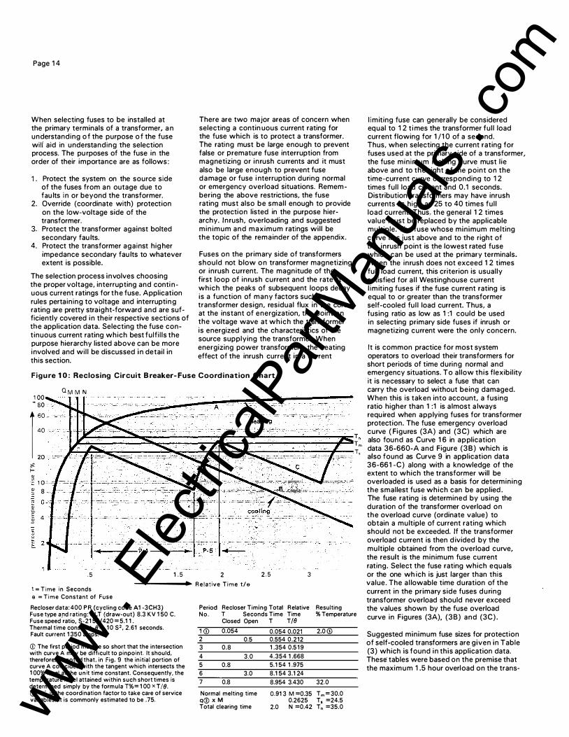
Page 1 4
When selecting fuses to be installed at the primary terminals of a transformer, a n understanding o f the purpose o f the fuse wili aid in understanding the selection process. The pu rposes of the fuse in the order of their importance are as follows :
1 . Protect the system on the source side of the fuses from an outage due to fau lts in or beyond the transformer.
2. Override (coordinate with) protection on the low-voltage side of the transformer.
3. Protect the transformer against bolted secondary fau lts.
4. Protect the transformer against hig her impedance secondary fau lts to whatever extent is possible.
The selection process involves choosing the proper voltage, interrupting and conti nuous current ratings for the fuse. Application rules pertaining to voltage and interrupting rating are pretty stra ight-forward and are sufficiently covered in their respective sections of the application data. Selecting the fuse continuous current rating which best fulf i l ls the purpose hierarchy listed above can be more involved and wil l be discussed in detail in this section.
There are two major areas of concern when selecting a contin uous current rating for the fuse which is to protect a transformer. The rating must be large enough to prevent false or premature fuse interruption from magnetizing or inrush currents and it must also be large enough to prevent fuse damage or fuse i nterruption during normal or emergency overload situations. Remem bering the above restrictions, the fuse rating must also be small enough to provide the protection listed in the purpose hierarchy. Inrush, overloading and suggested minimum and maximum ratings will be the topic of the remainder of the appendix.
Fuses on the primary side of transformers should not blow o n transformer magnetizing or inrush current. The magnitude of the first loop of inrush current and the rate at which the peaks of subsequent loops decay is a function of many factors such as transformer design, residual flux in the core at the instant of energization, the point on the voltage wave at which the transformer is energized and the characteristics of the source supplying the transformer. When energizing power transformers, the heating effect of the inrush current in a current
Figure 1 0 : Reclosing Circuit B reaker- Fuse Coordination Chart
Q M M N 1 00 - 80 40
l imiting fuse can generally be considered equal to 1 2 t i mes the transformer ful l load current flowing for 1 /1 0 of a second. Thus, when selecting the current rating for fuses used at the primary side of a transformer, the fuse minimum melting curve must l ie above and to the right of the point on the time-current curve corresponding to 1 2 times full load current and 0.1 seconds. Distribution transformers may have inrush currents as high as 25 to 40 times ful l load current. Thus, the general 1 2 times value must be replaced by the applicable multiple. The fuse whose minimum melting curve lies just above and to the right of the inrush point is the lowest rated fuse which can be used at the primary terminals. When the inrush does not exceed 1 2 times full load current, this criterion is usually satisfied for a l l Westinghouse current l imiting fuses if the fuse current rating is equal to or.greater than the transformer self-cooled ful l load current. Thus, a fusing ratio as low as 1 :1 could be used in selecting primary side fuses if inrush or magnetizing current were the only concern.
It is common practice for most system operators to overload their transformers for short periods of time during normal and emergency situations. To allow this flexibil ity it is necessary to select a fuse that can
1 60 . carry the overload without being damaged. When this is taken into account, a fusing ratio higher than 1 :1 is a lmost a lways required when applying fuses for transformer protection. The fuse emergency overload curve ( Figures (3A) and (3C) which are j�;:====:::s;;:;;:=====:;;;:;:;============�ST" also found as Curve 1 6 in application
}t--4�-...�----_;:::!loo�--4"-f-..::3-..,.�------_.;.;�lt---T m data 36-660-A and Figure (38) which is
# f-
'"
20
2 1 0 : .· � 8
"' 6 03
� 4 ::
T, :�-· ·=·..: :.·: ···""""'""'';;:"·'c''''"'c·:c:.�. · .. cc· .. :.::If,::;;;;.· .. : :.. also found as Curve 9 in application data
36-661 -C) along with a knowledge of the extent to which the transformer will be overloaded is used as a basis for determining the smallest fuse which can be applied . The fuse rating is determined by using the duration of the transformer overload on the overload curve (ordinate value) to obtain a multiple of current rating which should not be exceeded. If the transformer overload current is then d ivided by the multiple obtained from the overload curve, the result is the minimum fuse current rating. Select the fuse rating which equals
. 5 1 . 5 2
-------1� R e lative Time t/e
2 . 5 3 or the one wh ich is just larger than this value. The al lowable time duration of the current in the primary side fuses during transformer overload should never exceed
t = Time in Seconds e = Time Constant of Fuse
Recloser data: 400 P R (cycling code A1 -3CH3) Fuse type apd rating: C LT (draw-out) 8.3 KV 1 50 C. Fuse speed ratio, S-21 50/420 = 5.1 1 . Thermal time constant, 11 = . 1 0 S2, 2.61 seconds. Fault current 1 350 amps.
<D The first period may be so short that the intersection with curve A may be difficult to pinpoint. It should, therefore, be noted that, in Fig. g the initial portion of curve A coincides with the tangent which intersects the 1 00% level at the u n it time constant. Consequently, the temperature level attained within such short times is determined simply by the formula T%= 1 00 x T /II. (!) 'q' is the coordination factor to take care of service variables. It is commonly estimated to be .75.
Period No.
1 (i) 2 3
4 5 6
7
Recloser Timing Total Relative Resulting T Seconds Time Time % Temperature Closed Open T T/11
0.054 0.054 0.021 0.5 0.554 0.212
0.8 1 .354 0.5 1 9
3.0 4.354 1 .668
0.8 5.1 54 1 .975
3.0 8.1 54 3.1 24
0.8 8.954 3.430
2.0 (!)
32.0
Normal melting time q(i) X M
o.g1 3 M =0.35 T m = 30.0 0.2625 T, =24.5
Total clearing time 2.0 N =0.42 Tn =35.0
the values shown by the fuse overload curve in Figures (3A), (3B) and (3C) .
Suggested minimum fuse sizes for protection of self-cooled transformers are given in Table (3) which is found in this application data. These tables were based on the premise that the maximum 1 .5 hour overload on the trans-
www . El
ectric
alPar
tMan
uals
. com
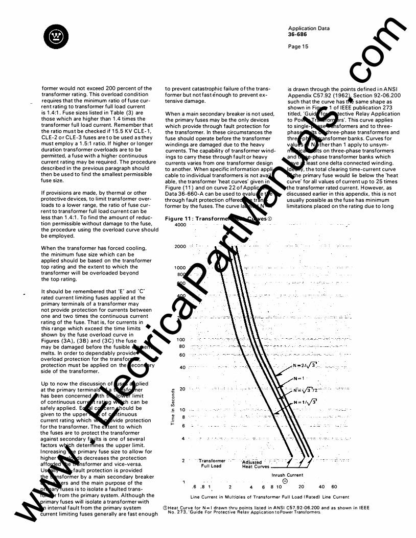
Cl
former would not exceed 200 percent of the transformer rat ing. This overload condition requires that the minimum ratio of fuse current rating to transformer full load current is 1 .4:1 . Fuse sizes l isted in Table (3) are those which are higher than 1 .4 t imes the transformer ful l load current. Remember that the ratio must be checked if 1 5.5 KV CLE- 1 , CLE-2 o r CLE-3 fuses are t o be used a s they must employ a 1 .5:1 ratio. If higher or l onger duration transformer overloads are to be permitted, a fuse with a higher continuous current rating may be required . The procedure described in the previous paragraph should then be used to find the smallest permissible fuse size.
If provisions are made, by thermal or other protective devices, to l imit transformer overloads to a lower range, the ratio of fuse current to transformer ful l load current can be less than 1 .4:1 . To find the amount of reduction permissible without damage to the fuse, the procedure using the overload curve should be employed.
When the transformer has forced cool ing, the minimum fuse size wh ich can be applied should be based on the transformer top rating and the extent to which the transformer wi l l be overloaded beyond the top rating.
It shou ld be remembered that 'E' and ·c rated current l imiting fuses appl ied at the primary terminals of a transformer may not provide protection for currents between one and two times the continuous current rating of the fuse. That is, for currents in this range which exceed the time l im its shown by the fuse overload curve in Figures (3A), ( 3 8 ) and (3C) the fuse may be damaged before the fusible element melts. In order to dependably provide overload protection for the transformer, protection must be applied on the secondary side of the transformer.
Up to now the d iscussion of fuses appl ied at the primary terminals of a transformer has been concerned with the lower l imit of continuous current rating which can be safely appl ied. Equal concern should be g iven to the upper l imit of continuous current rating which will provide protection for the transformer. The extent to which the fuses are to protect the transformer against secondary faults is one of severa l factors which determines the upper l imit. I ncreasing the primary fuse size to a l low for higher overloads decreases the protection afforded the transformer and vice-versa. Usually thru-fault protection is provided the transformer by a main secondary breaker or breakers and the main purpose of the primary fuses is to isolate a faulted transformer from the primary system. Although the primary fuses will isolate a transformer with an internal fault from the primary system current l imiting fuses generally are fast enough
to prevent catastrophic fai lure of the transformer but not fast enough to prevent extensive damage.
When a main secondary breaker is not used, the primary fuses may be the only devices which provide through fault protection for the transformer. In these circumstances the fuse should operate before the transformer windings are damaged due to the heavy currents. The capability of transformer windings to carry these through fault or heavy currents varies from one transformer design to another. When specific information applicable to individual transformers is not avai l able, the transformer 'heat curves' given in Figure ( 1 1 ) and on curve 22 of Application Data 36-660-A can be used to evaluate the throug h fault protection offered the transformer by the fuses. The curve labeled N = 1
Fig u re 1 1 : Transformer Heat Curves CD 4000
"' '0 c 0 <.> "'
"' .!: "' E i=
2000
1 000
800
600
400
200
1 00
80
60
40
20
1 0
8
6
4
2 Transformer , Adjusted Full Load Heat Curves
Application Data 36-686
Page 1 5
is drawn through the points defined i n ANSI Appendix C57.92 ( 1 962), Section 92-06.200 such that the curve has the same shape as shown in Figure 1 of I EEE publication 273 titled, 'G uide for Protective Relay Application to Power Transformers'. This curve applies to single-phase transformers and to threephase faults on three-phase transformers and three-phase transformer banks. Curves for values of N other than 1 apply to u nsym metrical faults on three-phase transformers and three-phase transformer banks which have at least one delta connected winding. Ideal ly, the total clearing time-current curve of the primary fuse would lie below the 'heat curve' for all values of current up to 25 times the transformer rated current. H owever, as discussed earlier in this appendix, this is not usually possible as the fuse has min imum l imitations placed on the rating due to long
( I I Inrush Current
0 . 6 .8 1 2 4 6 8 1 0 20 40 60
Line Current in Multiples of Transformer Fu ll Load ( Rated) Line Current
(]) H eat Curve for N = l drawn thru points listed in A N S I C57.9 2·06.200 and as shown in I EEE N o . 2 7 3 , ' G u ide For Protective Relay Application t o Power Transformers. www .
Elec
tricalP
artM
anua
ls . c
om
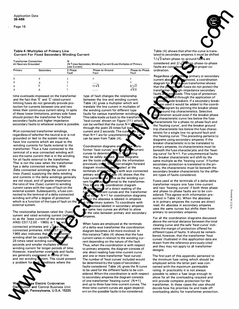
Application Data 36-686
Page 1 6
Table 4 : M ultiples of Primary Line Current For Fixed Secondary Winding Current
N Transformer Connection All Neutrals Grounded ( N Times Secondary Winding Current Gives M ultiples of Primary
Line Current)
Primary Secondary 3 Phase Phase-to-Ground Phase-to- Phase Fau� Fau� Fau�
y y A A
y A y A
time overloads i mpressed on the transformer and the fact that ' E' and ·c· rated current l imiting fuses do not generally provide protection for currents between one and two times their contin uous current rating. I n spite of these l ower l imitations, primary side fuses should protect the transformer for bolted secondary faults and higher impedance secondary faults to whatever extent is possible.
Wye connected transformer windings, regardless of whether the neutral is or is n ot grounded or tied to the system neutral. have l ine currents which are equal to the winding currents for faults external to the transformer. Thus a fuse connected to the term inal of a wye connected winding wi l l see the same current that is in the winding for a l l fau lts external to the transformer. This is not the case when the transformer has a delta connected winding. With delta connected windings the current in the l ines (fuses) supplying the delta winding and currents in the delta windings generally are not equal, and of greater importance the ratio of line (fuse) current to winding current varies with the type of fault on the external system. Subsequently, a fuse connected to the terminal of a delta connected winding wi l l offer a degree of protection which is a fu nction of the type of fault on the external system.
The relationship between rated line (fuse) current and rated w inding current ( referred to as the 'base current of the winding' in ANSI C57.1 2.00 - 1 965) is 1 fqr wye connected primaries and .Y 3 for delta connected primaries. ANSI C57.1 2.00 -1 965 also indicates that the transformer winding shal l be capable of withstanding 25 times rated winding current for 2 seconds and smal ler multiples of rated winding current for longer periods of time. However, transformer overloads and faults are genera l ly expressed in terms of l ine and not winding current. This could present a problem for fau lt conditions where the
Westinghouse Electric Corporation Distribution and Control Business U nit Pittsburgh, Pennsylvania, U.S.A. 1 5220
1 /-./ 3
1
2/·./3 ,;3/2
type of fault changes the relationship between the l ine and winding cu rrent. Table (4) g ives a multiplier which wi l l translate the line current in mu ltiples of the winding current for different type faults for various transformer windings. This table leads us back to the transformer 'heat curves' shown on Figure ( 1 1 ) where it can be verified that the curve N = 1 passes through the point 25 times full load l ine current and 2 seconds. The curves for other than N = 1 are for u nsymmetrical faults as can be seen from Table (4) .
Coordination diagrams employ the transformer 'heat curves' and fuse time-current curves to determine which fuse rating may be safely applied. These d iagrams are the tools used to apply the information previously cited. The most straight-forward d iagram involves fuses applied at the terminals of transformers with wye connected primary windings. Table (4) shows that the fuse current is the same as the winding current for all fau lts external to the transformer. This means the coordination d iagram consists simply of a direct read ing of the fuse time-current curves and the transformer 'heat curve' N = 1 for coord ination diagrams where the abscissa is labeled in amperes in the primary system. To coordinate with the abscissa labeled in secondary amperes the same two curves are shifted to al low for the ratio between primary and secondary amperes.
When fuses are employed at the terminals of a delta-wye transformer the coordination diagram becomes a bit more involved. In this instance Table (4) shows that the fuse current varies in relation to the winding current depending on the nature of the fault. Thus, when the coordination is with respect to primary amperes, the diagram consists of one direct reading fuse time-current curve and one or more transformer 'heat curves'. The number of 'heat curves' included would be determined by the types of secondary faults considered. Table (4) gives the N curve to be used for the d ifferent faults to be considered. When the coordination is with respect to secondary amperes the diagram consists of one transformer 'heating curve' ( N = 1 ) and up to three fuse time-current curves. The three time-current curves are again dependent on the possible faults to be considered.
Table (4) shows that after the curve is translated to secondary amperes it must be shifted 1 I .,;3 when phase-to-ground faults are considered and 2/ .,;3 when phase-to-phase faults are considered to obtain proper coordination.
Regardless of whether a primary or secondary current abscissa is employed. a coordination diagram for a delta-wye transformer shows that the primary side fuses do not protect the transformer for h igh- impedance secondary faults and overloads. This type of protection can be obtained through the appl ication of secondary side breakers. If a secondary breaker were used it would be added to the coordination diagram by plotting the breaker phase and ground trip characteristics. Selective coordination would exist if the breaker phase trip characteristic curve l ies below the fuse characteristic for a phase-to-phase fault and the 'heating curve', and the breaker ground trip characteristic lies below the fuse characteristic for a single l ine-to-ground fault and the 'heating curve.' The preceding pertains to diagrams using secondary am peres. If the breaker characteristic is to be translated to primary amperes, its characteristics must l ie beneath the fuse characteristic and the 'heating curve' for N = 1 . For u nsymmetrical faults the breaker characteristic wi l l shift by the same multiple as the 'heating curve'. I f further secondary protection is translated to the primary, the characteristic m ust lie beneath the secondary breaker characteristic for the different types of faults considered.
Fuses used at the terminals of a delta-delta transformer require one fuse time-current and two 'heating curves' if both three phase and phase-to-phase faults are to be considered. This agrees with information presented in Table (4) . When the abscissa is in primary amperes the curves are d i rect read. An abscissa in secondary amperes uses the same cu rves but shifts them from primary to secondary a mperes.
For all the coordination d i agrams discussed above the vertical distance between the total clearing curve and the safe 'heat curve' indicates the margin of protection offered for d ifferent types of faults. It should be remembered, however, that the transformer 'heat curves' i l l ustrated in this application data are drawn from the reference previously cited and they may not apply to all transformer designs.
The first part of this appendix pertained to the minimum fuse rating which should be employed whi le the latter part was concerned with the maximum permissible rating. In practical ity it is not a lways possible to select a fuse large enough to al low for a l l the overloading required and sti l l provide complete protection for the transformer. In these cases the user should decide how his priorities l ie and trade off overloading abi l ity for transformer protection. www .
Elec
tricalP
artM
anua
ls . c
om