Embed Size (px)
Citation preview

:
I
Medium Voltage Line Up Top Mounted Horizontal Main Bus with Incoming Line Two High 400 Amp Induction Motor Starter and One High 800 Amp Induction Motor Starter
Table of Contents General Description . . . . . . . . . . . . . . . . 2 Personnel Safety Features . . . . . . . . . . 3 Illustrated Operation Instructions. . . . 4 Test Run Circuit. . . . . . . . . . . . . . . . . . . . 5 User Benefits . . . . . . . . . . . . . . . . . . . . . . 6 Component-to-Component Circuitry 7 Drawout Vacuum Contactor
Slide Out . . . . . . . . . . . . . . . . . . . . . . . . 8 Roll Out . . . . . . . . . . . . . . . . . . . . . . . . . 9
Mechanical Isolation Switch . . . . . . . . 10 Current Limiting Fuses . . . . . . . . . . . . . 11 Low Voltage Control . . . . . . . . . . . . . . . 12 Typical Control Schematic . . . . . . . . . . 13 Starter Type
Slide Out Design . . . . . . . . . . . . . . . . . 14 Roll Out Design . . . . . . . . . . . . . . . . . . 15 Reduced Voltage. . . . . . . . . . . . . . . . . 16 Synchronous . . . . . . . . . . . . . . . . . . . . 17
Modifications Incoming Line & Potential Transformers . . . . . . . . . . . . . . . . . . . . 18 Load Break Switches Main Horizontal Bus . . . . . . . . . . . . . . 19
Motor Protection & Metering . . . . . . . 20 Communications . . . . . . . . . . . . . . . . . . . 21 Starter Configuration . . . . . . . . . . . . . . . 22, 23 Enclosure Type . . . . . . . . . . . . . . . . . . . . 24 Contactor- Fuse Coordination . . . . . . 25 Technical Data
400 Ampere . . . . . . . . . . . . . . . . . . . . . 26 800 Ampere . . . . . . . . . . . . . . . . . . . . . 27
Typical Specification . . . . . . . . . . . . . . . 28 www . El
ectric
alPar
tMan
uals
. com

Descriptive Bulletin 8850 Page 2
AMPGARD Medium Voltage Starters Description
General Description
Westinghouse Ampgard medium voltage starters provide complete flexibility in precisely matching a wide range of industrial motor ratings. Rated at 2500, 5000, and 7200 volts, up to 8000 Hp, Ampgard starters are the first motor starters designed as integrated, complete units. Uniformity of design throughout the Ampgard line allows the use of the optimum rating for each application within a plant with no mixed equipment problems. And the variety of optional features that are available with Ampgard allow a user to obtain a starter unit that exactly
meets a motor's starter and control requirements.
Complete front accessibility to the enclosures allows free standing, back-to-back, or against-the-wall starter mounting.
Ampgard starters are available in 400 amp and 800 amp (open rating) for 2500, 5000 and 7200 volt ratings. The 400 amp rating in a NEMAIEEMAC Type 1 enclosure is 36 inches wide, 30 inches deep and 90 inches high (100" with top mounted horizontal bus) either one or two high construction for full voltage starters. The 800 Amp rating in an
enclosure is 40 inches wide, 30 inches deep and 90 inches high (100" with top mounted horizontal bus) in a one high construction for a full voltage starter. These floormounted units are uniform in design and easily adapted for reversing, reduced voltage, synchronous, and wound rotor motor starting.
For flexibility and space economy, no other starter can compare with the Ampgard starter line.
Ampgard is industry's "first family" of high voltage starters.
400 Amp Two High Construction Induction Motor Control 800 Amp With Protective Relays and Meters in Top 30" of Enclosure (When Specified)
Motor Starter Nameplate Data
l Main Horizontal Bus
Lifting Eyes for / Single Structure
Q Shipments
� (When Specified! ---:--- [N.\::•c,�l] . ��� �����-H� _.,Il _'�� 'Ol;m;·GE;· �����
Through 1500 HP at 2200-2400 Volts Through 2500 HP at 4000-4800 Volts Up to 4000 HP at 7200 Volts 36" Wide
•••
1501-3000 HP at 2200-2400 Volts 2501-5500 HP at 4000-4800 Volts Up to 8000 HP at 7200 Volts 40" Wide
October, 1989
I
www . El
ectric
alPar
tMan
uals
. com

.·
"·
Personnel Safety features
One of the most important considerations in designing the Ampgard Starter was personnel safety. The result is an extensive system of interlocks and other safety features.
Interlocks Interlocking on Ampgard Starters includes:
• Isolating switch handle housing extends over medium voltage door when handle is in ON or OFF position, preventing door from being opened.
• Position for optional key interlocks.
• When door is open, detent prevents operating handle from being moved inadvertently to OFF or ON position.
Descriptive Bulletin 8850
Page 3
AMPGARD Medium Voltage Starters Personnel Safety Features
Detent ·When contactor is energized, isolating
switch cannot be opened or closed. Shutter Barrier Between Line Terminals and Fuse Stabs
Extra Interlock to Prevent Accidental Shutter Operation When Isolation Switch is Removed
Distinctive Marking When Shutter is in Closed Position
Shutter Operated by Moving Tray When Isolation Switch is in Positi
Motion of Shutter
Rail on Which Isolation Switch Mounts
Shutter Mechanism and Finger Barrier Isolation of Incoming Line Stabs
October, 1989
Other Safety Features In addition to the interlock system, Ampgard Starters include many other features designed to protect operating personnel. These features include:
• Provision for three padlocks on isolating switch handle in OFF position.
• Operating handle must be rotated 90° to the horizontal service position in order to open main door, assuring complete isolation from the main power source.
• Shutter barrier between line terminals and fuse stabs are mechanically driven in both directions. (See Photo)
• Distinctive marking on back of switch assembly appears when shutter barrier is in position and starter is completely isolated from the line.
• Visible grounding clips provide a positive ground of the starter and the enclosure when the isolating switch is opened.
• High and low voltage circuits are compartmentalized and isolated from each other.
• Illustrated selected safety features, operating instructions and renewal parts information are permanently mounted inside main enclosure door. Refer to page 4. www .
Elec
tricalP
artM
anua
ls . c
om
Descriptive Bulletin 8850
Page 4
AMPGARD Medium Voltage Starters Personnel Safety Features
Ampgard· I.L. 17201
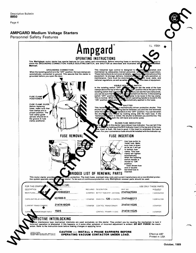
OPERATING INSTRUCTIONS Thla Waallnghouae motor alarter hat apeelat leaturea lor your safely and convenience. Before removing lutes or aervlclng lhlt otarter, be sure to check the GROUNDING CONNECTION, VISIBLE ISOLATING SWITCH, and SHUTTER at d"serlbed and tllullrat"d below. s .. lnatructlon ll•nu•l·
G ROUNDING CONNECTION When the laolallng switch la in the "OFF" position, the Ius" clamps are automatically connected to ground. Thla aaaurea that the otarter is grounded before you open the door.
FUSE CLAMP POSITIONER
FUSE CLAMP GUIDE Before replacing tueet, make sure thai tute clamps are In proper position. The fuse clamp guide (arrow) should be In the groove In fuee clamp positioner.
,
FUSE REMOVAL Hook luae puller thru eyes on fuse. Pull fuae lorward sharply and slide out over contactor.
This lnduolrlal type control Is designed to be Installed, operated, and maintained by adequately trained personnel, with edequate supervision. These lnatruetlo"" do not cover all details, variations, or combinations ol the equipment, Ito storage, delivery, lnotallatlon. cheek-out, tale operation, or maintenance. Care must be exercised to comply with local, alate, and national regulations, aa well aa safely practlceo, lor thlo cla11 ol equipment.
VISIBLE ISOLATING SWITCH In the ioolatlng twitch "OFF" position you can tee the ends ol the lute clamps above the top of the fuoeo. In the "ON" position lhlo to the part of the Isolating owlteh that connect• to the llne.l l you can see the fuse clamp endo, you can be sure that the starter Is disconnected from the line. In lhe loolatlng twitch "OFF" position, the lusea will appear to be loose In the top clamp. This Is normal. When the Isolating switch operating handle Ia moved to the "ON" position, adequate Ioree It automatically applied to the luaeo.
SHUTTER Thla laolatlng switch has a mechanically driven protective shuller. Thla shutter provides an lnoulatlng barrier between you and the line terminals when the Isolating switch handle Is In the "OFF" position. You can tell when the shutter It fully closed by looking along old" the main luae. II the "barberpole" pattern is visible, the shuller Is between you and the line. The "barberpole" Is on both the tell-hand and center poles.
BLOWN FUSE INDICATION The main luses ln lhla starter have a blown fuse Indicator. You can tell lithe fuse Ia blown by looking at the RED Indicator lntert ln fhe lop end ol the fuse. lithe Insert Ia lluah, the fuse Is good. II the Insert It extended, the luae Is blown. For your convenience luoeo should be lnatalled with the Indicator up.
FUSE INSERTION Use fuse puller lo Install fuse. Make sure hJae is down as far a1 It will go in bottom fuse clamp. This fuse clamp wilt tighten automatically when the loolellng switch handle Is moved to "ON" position.
ABRIDGED LIST OF RENEWAL PARTS
Intel ahowa how end of double barreled fuse is Inserted.
This motor starter provides Improved motor protection. The main fuses, overload relay eons and current transformers are a eoordlneted protec� live system specially selected for your motor. To be sure of continuous protection only WestinghOuse renewal parta ahould be used.
FOR THIS STARTER NO XL42310-1 (1F) £?.S§_(:RIPTf0� MAIN FUSES 200A-9R
OVER;..OAD RELAY HEATEr1S
CURRENT TRANSFORMERS
CURRENT TRANSFORMER RATiO
PART NO
151D933G01
IQ1000··-··II·---�-
2147A16G05
150/5
PROTECTIVE INTERLOCKING
�·--········ �------ USE ONLY THESE PARTS REQUIRED DESCRIPTION
31STARTER
PART NO
2147A47G03 --�� .. ·��··-
------
1 STARTER MAiNC011!120 VCONTROLi 2147A�G1_1 _
1 STARTER CON-mOL TAANS�ORMER 2147A11G05
CONTROL PRIMARY ?USES 2147A11G25
RFQ'd'.f1g>
1 CONTACTDR
1 CONTACTOR
l/STAI1TER
2tS TARTER
Positive lnterterence type mechanical Interlocks are used exclualvely on lhta starter. They protect you by causing the mechanism to lock II Incorrect operation Ia atlempted. II this happens, or It some other symptom of Incorrect adjustment lo evident. DO NOT fORCE the mechanism. Reier to the Instruction book before making changes or applying Ioree.
O:OMTIIID� 01¥>.10,. WUTIIMIMO� ft-.Cf11!!(: <;OIIIP Al>oi(V1Ut .. C (:_ ..... *>-0, ... ..,._ liKM< t:<lfP<"OIII...,
CAUTION •••• INSTALL 4 PHASE BARRIERS BEFORE OPERATING VACUUM CONTACTOR UNDER LOAD. Effective 4/87
Printed in USA
October, 1989
·"""·
www . El
ectric
alPar
tMan
uals
. com

.·
Descriptive Bulletin 8850
Page 5
AMPGARD Medium Voltage Starters Personnel Safety Features
Test-Run Circuit
A built-in test circuit permits the checking of the starter control circuit and pilot circuits. This testing is performed when the high voltage is de-energized and isolated. Thus, both visual, mechanical and electrical inspection may be performed while checking the control circuit.
The plug is disconnected from the secondary side of the control transformer and inserted into an external plug. This prevents
the possibility of back feeding through the control transformer from an external test power source.
The control circuit permits testing of the contactor in its normal position or in the drawout position.
In the test mode, the polarized plug connects the control circuit to an external 115 volt, 60 Hertz supply. In the run mode, the control circuit is energized from the secondary of the control transformer.
Receptacle on Secondary Side of Step Down Control Transformer
Interference Bar
Vacuum Roll Out Design
Proper contactor load stab connection is important. The Ampgard has two visible checks. • Contactor must be fully inserted in cell for
latch mechanism to be behind contactor rail positioner.
• There is a mechanical interference bar as an additional backup. If the contactor is not in the proper position, the interference prevents closing of the high voltage door.
Feeler Gauge to Check Vacuum Contact Wear
Contactor Positioner
Polarized Plug Removed for Inserting into External115 Volt Test Power Insures Against Back Feed Through Control Transformer
October, 1989
Auxiliary Interlocks Type L-64 2-NO 2-NC Standard
400 Ampere Vacuum Roll Out Contactor
www . El
ectric
alPar
tMan
uals
. com

Descriptive Bulletin 8850 Page 6
AMPGARD Medium Voltage Starters User Benefits
Personnel Safety: Equipped with a mechanically driven isolating shutter, the positive mechanical isolating switch completely grounds and isolates the starter from the line connectors, leaving no exposed high voltage when the door is open. The shutter mechanism is visible without the removal of any components. The high voltage door is mechanically locked/closed with the isolat-ing switch handle; the low voltage section is separated from the high voltage section.
Ease of Installation: Current limiting fuses, contactor assembly, and isolating switch are easily removed from the enclosure. There is no need to remove any structural or mechanical barriers for accessibility to motor load terminals.
Ease of Maintenance: Because all components are front accessible, routine inspection and parts replacement is fast and easy. The control circuit permits testing of the contactor in its normal position or in the draw-out position.
Simplicity of Design: Component-to-component design eliminates half of the electrical connections normally required with other motor starters.
Complete Testing: Designed, tested, and verified in the Westinghouse High Power Laboratory, Ampgard Motor Starters comply with ANSI/NEMA, ICS-2, EEMAC E14-1, UL 347, and CSAC22.2 No. 14, published industrial control standards. BIL ratings are established in accordance with ANSI/IEEE standards. Third party labeling is not included as standard. If the starter bill of material fits within certain restrictions, the starters can be supplied with UL, CSA or City of L.A. Certification. Contact the factory to determine if a certain starter meets the requirements for labeling.
For flexibility and space economy, no other starter can compare with Ampgard Starters. All Ampgard Starters feature the same basic design and are installed, operated, and maintained the same way.
Starter Classes are available for the follow-ing non-reversing applications: 400 Ampere Starter Class S/V 202- Induction Motor Full Voltage Class S!V-502- Induction Motor Primary Reactor Class SIV 602 Induction Motor Autotransformer Class S!V W02 - Wound Rotor Motor Class SIV F02- Synchronous Motor Full Voltage Class S!V R02 - Synchronous Motor Primary Reactor Class S!V A02 Synchronous Motor Autotransformer
S =Slide Out Contact or V = Roll Out Contactor
Reversing also available.
Design Features
Type SJ 400 Amp Vacuum Contactor
. 2 Type LFR Mechanical Isolating Switch
3 ·Current Limiting Type CLS Power Fuses
. ,. Control Compartment
'Illustrated Safety Features and Parts List
·. Motor Load Terminals
Cl
October, 1989 www . El
ectric
alPar
tMan
uals
. com
l'
Component-to-Component Circuitry
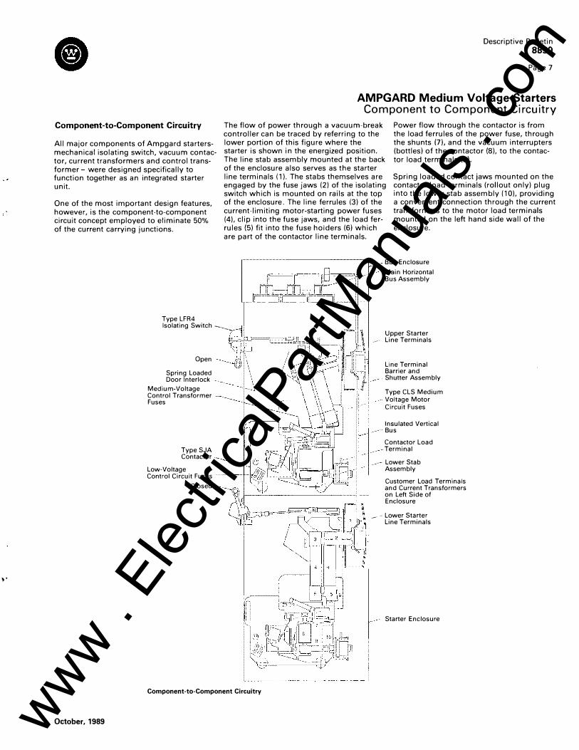
All major components of Ampgard startersmechanical isolating switch, vacuum contactor, current transformers and control transformer were designed specifically to function together as an integrated starter unit.
One of the most important design features, however, is the component-to-component circuit concept employed to eliminate 50% of the current carrying junctions.
Type LFR4
Descriptive Bulletin 8850
Page 7
AMPGARD Medium Voltage Starters Component to Component Circuitry
The flow of power through a vacuum-break controller can be traced by referring to the lower portion of this figure where the starter is shown in the energized position. The line stab assembly mounted at the back of the enclosure also serves as the starter line terminals (1 ). The stabs themselves are engaged by the fuse jaws (2) of the isolating switch which is mounted on rails at the top of the enclosure. The line ferrules (3) of the current-limiting motor-starting power fuses (4), clip into the fuse jaws, and the load ferrules {5) fit into the fuse holders (6) which are part of the contactor line terminals.
Power flow through the contactor is from the load ferrules of the power fuse, through the shunts (7), and the vacuum interrupters (bottles) of the contactor {8), to the contactor load terminals (9).
Spring loaded contact jaws mounted on the contactor load terminals (rollout only) plug into the lower stab assembly (1 0), providing a convenient connection through the current transformers to the motor load terminals mounted on the left hand side wall of the enclosure.
- Bus Enclosure
Main Horizontal Bus Assembly
Isolating Switch ---...__
October, 1989
Open
Spring Loaded Door Interlock
Medium-Voltage Control Transformer Fuses
Type SJA Contactor
Low-Voltage Control Circuit Fuses ���+--J,;.:;J'i;'
Closed
Component-to-Component Circuitry
Upper Starter ,-, Line Terminals
Line Terminal Barrier and Shutter Assembly
Type CLS Medium Voltage Motor Circuit Fuses
Insulated Vertical · Bus
Contactor Load Terminal
Lower Stab Assembly
Customer Load Terminals and Current Transformers on Left Side of Enclosure
� -Lower Starter Line Terminals
Starter Enclosure
www . El
ectric
alPar
tMan
uals
. com

Descriptive Bulletin 8850 Page 8
AMPGARD Medium Voltage Starters Drawout Vacuum Contactor Features
Type SJA 400 Amp Vacuum Contactor Slide Out
Contactor Load Side Cable Connects to Termination On Left Hand Wall of Structure
Step Down Control Transformer
Pull Apart Terminal Blocks to Works in the Drawer Control Panel
Test Receptacle and Plug Rear View
The Type SJ Vacuum Contactor was designed and engineered specifically for use in Ampgard Starters. It is a self-supporting, compact, drawout, three-pole, De Magnet closed contactor. To permit application matching of the starter to the motor rating, the SJ Contactor is available for 2200 through 7200 volts at ratings of 400 and 800 amperes. The 400 amp contactor is available in both the standard slide out configuration and the optional roll out design. The 800 amp contactor is available in the roll out design only.
Design The Type SJ Vacuum Contactor is a highly versatile, low-chop contactor that has been designed and tested to withstand a 60,000 volt basic impulse level. The contactor complies in all respects with published NEMA Industrial Control standards and is a UL recognized component. The SJ is designed for starting and controlling 3-phase, 50i60 hertz ac motors on nominal 2500, 5000, and 7200 volt systems.
The Type SJ accommodates mechanical interlocks between itself and other contactors and the isolating switch. These time proven interlocks provide unmatched safety and service protection.
The Type SJ Vacuum Contactor consists of a molded chassis with crossbar, magnet, and vacuum interrupters. The contactor is easily positioned into the starter and longlife vacuum bottles provide many operations with a minimal maintenance program. The contactor employs special main contact materials that exhibit an extremely low chopping current which minimizes switching surge. Surge protection is therefore not required due to the use of the vacuum contactor. Surge suppression may be required, however, for reasons other than the vacuum contactor.
The contactor design incorporates fuse clamps for the load side of the current limiting fuses and provides for connection to the high voltage side of the control power
Mounting For Load Side Main Power Fuses
3 Phase Current Transformer
Zero Sequence Ground Fault Transformer (When Required)
transformer. CPT's of up to 2 KVA capacity are mounted on the contactor. The contactor operating coil has a built-in full wave silicone rectifier which supplies DC power for quiet operation and allows for proper contactor-fuse coordination.
Refer to pages 26 and 27 for complete technical specifications.
Maintenance Ease of maintenance is one of the outstanding features of the Westinghouse Vacuum Contactor line. A simple goino go gauge for checking contact wear is included with each contactor. It is not necessary to drawout the contactor to check for contact wear or to replace the main operating coil or electrical interlocks mounted on the contactor. All are front accessible. The vacuum contactors are also much lighter than the previous generation airbreak contactors, which allows for easier insertion and removal from the starter structure.
October, 1989 www . El
ectric
alPar
tMan
uals
. com

�,>
Descriptive Bulletin 8850
Page 9
AIVIPGARD Medium Voltage Starters Drawout Vacuum Contactor Features
Type SJA 400 Amp Vacuum Contactor Roll Out with Wheels and Load Fingers
Mechanical Interlock Interface to Isolation Switch Phase Barriers
Mounting for Load Side Main Power Fuses (Line Side of Fuse Held by Mechanical Isolation Switch)
Test Receptacle and Plug ,,_,...,....,. ............. Connection to
Isolating Switch Electrical Interlock
Roll Out Wheels
Note: Each Contactor supplied with a Feeler Gauge to Check Contact Wear from Front of
Self Aligning Contactor Load Fingers Latch Mechanism Visual
Check to Insure Contactor Completely Rolled In
Starter
Front View
400 Amp Slide Out The slide out version of the SJ Contactor is supplied as standard for those applications requiring a 400 Amp Contactor. The contactor slides into the Ampgard structure on steel rails. Medium Voltage cables connect the contactor load terminals to the lug landings for the motor load cables. A 3-phase current transformer and, when required, 3-phase potential transformer and ground fault zero sequence current transformer, are mounted on the contactor. A pull apart terminal block connects the contactor to the low voltage control panel.
The contactor is easily removed from the structure by removing 3 bolts securing the load cables, 1 bolt in each of the two mounting rails and one bolt connecting the isolating switch interlock arm.
400 Amp Roll Out A roll out version of the 400 Amp Contactor is an available option. The roll out contactor is mounted on wheels and simply rolls into the Ampgard structures. Contactor load fingers engage a load stab as the contactor is inserted into the structure. The contactor is latched in position and it can easily be
October, 1989
Rear View
removed by releasing the latch mechanism (refer to Page 5). This allows the contactor to be removed from the starter without disconnecting any medium voltage cables.
The 400A roll out contactor is electrically and mechanically interchangeable with the previous generation 2500/5000V, 400 ampere airbreak contactor.
800 Amp Roll Out The 800 ampere Vacuum Contactor is available in a roll out design only. It has the same basic features as the 400 amp roll out.
Optional Contactor Features All Ampgard Medium Voltage Contactors are available with a mechanical latch attachment (mechanically latched versus magnetically held closed). The latched design is used on applications where the contactor must remain closed through a voltage dip or voltage failure. The contactor is opened (tripped) by energizing a separate electrically operated solenoid with either one or two operating trip coils of different voltages.
Reversing, reduced voltage and multi-speed contactors are also available.
800 Amp VacuOJm Break Contactor 7200 Volt Maximum Roll Out with Wheels and Load Fingers www .
Elec
tricalP
artM
anua
ls . c
om

Descriptive Bulletin 8850
Page 12
AMPGARD Medium Voltage Starters Low Voltage Control
Isolated low Voltage Control (Works in the Drawer)
Mounted on the right side of the enclosure, the low voltage control panel is completely
isolated and barriered from high voltage and has a separate low voltage access door.
,_.--- V. Turn Door latch Top and Bottom
low Voltage and High Voltage Doors Closed
The Device Panels, 10·1000 and 10 Data Plus II All Fit in this Same Size Low Voltage Door Cutout
10·1000 II (When Specified)
Indicating lights Emergency Stop Push Button (When Specified)
Device Panels
Current Transformer Shorting Terminal Blocks (When Specified)
----�� Routing of Control Wire in-----�-----Wire Channel
Interposing Control Relay -----------DIN Rail Mounted
Wiring Is Protected Between ----------Low Voltage Panel and Hinged Low Voltage Door
Low Voltage Panel Completely Extended
Note Isolation Switch Handle Mechanically Blocking High Voltage Door
Customer Terminal Block for Remote Control Connections
Low Voltage Door Open Low Voltage Panel Partially Drawn Out - High Voltage Door Closed
--::::.--- Rear of '14 Turn Fastener
Predrilled Holes for Additional Control Devices
10·1 000 II Rear View
.,-----Indicating Lights and Pushbutton Rear View
----Blank Device Panel
�:--+----- Note Low Voltage Door is Hinged to Slide Out Control Panel
October, 1989 www . El
ectric
alPar
tMan
uals
. com

•
Descriptive Bulletin
8850
Page 15
AMPGARD Medium Voltage Starters Starter Types
400 Ampere Cell with Roll Out Contactor Design 400 Ampere Cell With Main Power Fuses and Roll Out Contactor Removed
Horizontal Bus Splice Plates (Bolted In Starter Cell During Shipment)
Customer Motor Load Connection for Top Entry
Vacuum Contactor-Roll Out With Wheels and Load Fingers Contact Guide Rails
400 Ampere Cell With Main Power Fuses, Roll Out Contactor and Isolating Switch Removed
October, 1989
Current Transformer Panel
Customer Motor Load Connection for Bottom Entry (Current Transformer Panel Reversed for Top Entry)
Motor Load Cable Space Bottom Entry
Contactor Load Stabs
www . El
ectric
alPar
tMan
uals
. com

Descriptive Bulletin
8850
Page 16
AMPGARD Medium Voltage Starters Starter Types
Reduced Voltage Starting
Starters for synchronous motors are also available in either reactor or autotransformer type. Both provide closed transition from reduced voltage to full voltage.
Reduced Voltage Starter Reactor or Autotransformer Type Induction Motor Starter
� ..
The 400 ampere 2300-7200 volt reduced voltage starters are structured two wide for a total of 72" width, 30" deep and 90" high (without Main Bus).
Lifting Angles Shipment of Structures
Customer Motor Load Connections
R (Run
Reduced Voltage Reactor Type Slide Out Contactor Design
Hinged Door Mechanically Key Interlocked to Isolating Switch Reduced Voltage Autotransformer Type
Slide Out Contactor Design
Main Contactor
Customer Motor Load Connections
Door Removable by-----Removing Pins
R (Run Contactor) -----'
S (Start Contactor) ------'
Start and Run Contactor Both Mechanically and Electrically Interlocked
Autotransformer with Standard Taps 50%-65%-80%
Main Contactor
Customer Low Voltage Connection Terminal Block
Fuse Puller
October, 1989 www . El
ectric
alPar
tMan
uals
. com

Typical Diagram for Vacuum Type SJ Contactor
System Voltage L3 Main Fuse GFCT
Descriptive Bulletin 8850
Page 13
AMPGARD Medium Voltage Starters Typical Control Schematic
o�----� �------[:]�------------� r-----frr----�======����--
Gnd.
IQ-1000 II
Start _L
M
M
M
Xl X2 GF1 GF2
Pri. Fuse 3 Amp
1 Plug Sec. Fuse 120V
MX
Xl X2 120Vf;J
1A ISW
1C 1 Rcpt. 120V
MX
"RUN"
"OFF"
* "OFF"
Induction Motor Across-The Line Starter
Vacuum Contactor With Optional IQ-1000 II Motor Protection, Local & Remote Start-Stop Pushbuttons and Local & Remote Red and Green Indicating Lights.
October, 1989
Cust. 120V Test. Power
X1 y =. j X2
��Cust. "'-.:/ Rcpt.
��-------l
I PW + Rect. I
M
IQ
11 12 IQ Trip
Mode #1
* Remote
M M
Spare Interlocks r1r1 www . El
ectric
alPar
tMan
uals
. com

Descriptive Bulletin 8850 Page 14
AMPGARD Medium Voltage Starters Starter Types
Induction Motor Across· The-line Starter
400 Ampere Cell Slide Out Design 400 Ampere Cell with Main Fuses and Slide Out Contactor Removed
Extra Capacity 2 KVA Control Transformer (600VA Standard)
Contactor Slides Out on Guide Rails
Contactor Guide Rails
400 Ampere Cell with Main Power Fuses, Slide Out Contactor and Isolating Switch Removed
Customer Motor Load Connection Same for Top or -...ti.i' .... 41'1':"" Bottom Entry
Motor Load Cable Space Bottom Entry
Mechanical Interlock Connection Between Isolation Switch and Contact or
October, 1989 www . El
ectric
alPar
tMan
uals
. com
Descriptive Bulletin 8850
Page 17
AMPGARD Medium Voltage Starters Starter Types
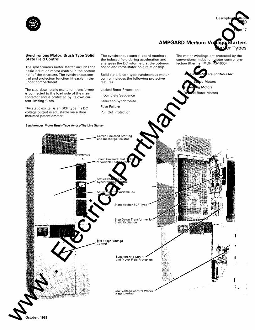
Synchronous Motor, Brush Type Solid State Field Control
The synchronous motor starter includes the basic induction motor control in the bottom half of the structure. The synchronous control and protection function fit easily in the upper compartment.
The step down static excitation transformer is connected to the load side of the main contactor and is protected by its own current limiting fuses.
The static exciter is an SCR type. Its DC voltage output is adjustable via a door mounted potentiometer.
The synchronous control board monitors the induced field during acceleration and energizes the DC rotor field at the optimum speed and rotor-stator pole relationship.
Solid state, brush type synchronous motor control includes the following protective features:
Locked Rotor Protection
Incomplete Sequence
Failure to Synchronize
Fuse Failure
Pull Out Protection
Synchronous Motor Brush-Type Across· The-Line Starter
October, 1989
Screen Enclosed Starting and Discharge Resistor
Shield Covered Heat Sinks of Variable Static Exciter
Static Excitation and Synchronizing Control
___ M,u1ustment for Variable DC Voltage
Static Exciter SCR Type
Step Down Transformer Static Excitation
Low Voltage Control Works in the Drawer
The motor windings are protected by the conventional induction motor control protection (thermal, MOR, IQ-1000).
Also available are controls for:
Multi-Speed Motors
Reversing Motors
Wound Rotor Motors
i
I
I
I
www . El
ectric
alPar
tMan
uals
. com

Descriptive Bulletin 8850 Page 18
AMPGARD Medium Voltage Starters Optional Modifications
Incoming Line An incoming line enclosure is recommended, depending upon the size and number of incoming cables. Different designs are available for incoming power for top or bottom entry.
Shown is a 26" Wide Incoming Line Structure
The addition of incoming line metering requires a 36" wide strucure in lieu of a 26" wide structure.
Refer to Price List 8810, structure modifications, for different line cable and incoming line switch arrangements.
U Shaped Copper Adaptor can be Reversed for Bottom Entry
Bus and Lugs for Top Entr'! Incoming Power
ADM Switch Ratings
Interrupting Capacity
aximum BIL Continuous (Amperes)
Voltage Rating Current f--------�--------
Kilovolts) (kV) (Amperes) 1 at at
1 80% PF 10% PF
M
----- - -- - - -
5.5 60 600 600 80 5.5 60 1200 1600 I 300
----
Momentary Current -- ---------
10 cycles 4 seconds Asymmetrical Symmetrical
(Amperes) (A� peres)
40,000 25,000 61,000 38,000
Fault
Draw out Potential Transformers and Fuses
Draw out trunnion-mounted potential transformer design with fuses is available to meet specific application requirements or code regulations.
Draw-out Potential Transformer and Fuses Mounted in a 36" Wide Structure, Height 15"
Type ADM Load Break Switch Shown With Safety Screen Removed
Current l Closing
Asymmetrical i (Amperes) I
_ _J 40,000 I
61,000 -�
October, 1989 www . El
ectric
alPar
tMan
uals
. com

Main Bus When starters are grouped together in a line-up, a typical option is the main bus. The Ampgard main bus is mounted in its own 10-inch high enclosure, which isolates it from the starter. The connection from the
Vertical Bus Drops
Type ADM Load Break Switch For application needs with loads rated 600 or 1200 amps at 2500, 5000 and 7200 volts, Ampgard is available with the Type ADM load-break switch. This device, a three-pole, manually operated, quick make-quick break switch, is used primarily as a disconnect switch in Ac power systems. This switch is fixed mounted and will fit in one half of a standard 90-inch high, 36-inch wide vertical structure. Power fuses up to 400E amperes can be mounted within the half high structure. Mechanical interlocks are incorporated
October, 1989
Descriptive Bulletin 8850
Page 19
AMPGARD Medium Voltage Starters Optional Modifications
main bus to the starter is done with rigid vertical bus. Insulated barriers are provided for separate top entry of power and control cables. The main bus is top, side and front
accessible, which allows for ease of maintenance or extension of line-ups without
Back to Back with Cross Over Bus
so that the door cannot be opened when the switch is on, and when the door is open the switch cannot be closed. A safety screen is supplied behind the switch door. The Type ADM switch can be supplied with a total of four electrical interlocks.
Other Optional Modifications In addition to the options previously described, Ampgard starters are available with a variety of accessories and modifications to satisfy a wide range of application requirements. Some of the broad areas
disassembling the starters. All bus is braced to withstand the let through energy allowed by the starter fuses during a 50,000 amp (symmetrical) fault.
covered include:
Insulated Barrier to Separate Motor Load Cables from Main Bus
Low Voltage Conduit Area
Bus Splice Plates
• Bus and cable entrance enclosures (See photos)
• Transformers • Power factor correction capacitors • Pilot devices • Instruments and meters • Control relays and timers. • Solid state or selected electro-mechanical
protection devices
For more details on available accessories and modifications, refer to PL 8810.
www . El
ectric
alPar
tMan
uals
. com

Descriptive Bulletin 8850 Page 20
AMPGARD Medium Voltage Starters Optional Motor Protection, Metering & Communications
10-1000 II
Maximizes Motor Utilization The 10-1000 II is a microprocessor based multifunction, motor protective relay that monitors three phase AC current and makes separate trip and alarm decisions based on pre-programmed motor current and temperature conditions.
It is capable of combining the effects of temperature, time, current (both positive and negative sequence) and true RMS into a single, protective system. By including all possible protection functions, whether utilized or not, a degree of standardization is achieved for the consultant, user and manufacturer. The 10-1000 II allows the motor to run as long as possible, allowing full utilization of the motor in addition to its basic function of protecting the motor.
Optimum Motor Protection By simply programming the 10-1000 II with the motor's electrical characteristics (such as full load current and locked rotor current), the 10-1000 ll's algorithm will automatically tailor the optimal protection curve to the motor being monitored. No approximation is needed in selecting a given protection curve because the 10-1000 II matches the protection from an "infinite" family of curves, to each specific motor.
Application-related motor load problems are further addressed through the use of such functions as Jam, Underload, and Ground Fault protection. The 10-1000 II provides a cost effective alternative to several conventional protective relays including short-time and long time-time current relays, instantaneous overcurrent relays, ground fault relays, phase loss or phase unbalance relays, and more protection features.
Features • The 10-1000 II provides a "snapshot" of all monitored values immediately prior to the time of trip providing valuable trouble shooting/maintenance information.
• A minimum number of Electrical Connec-tions are required for basic protection
6 Current Transformers 2- Ground Fault Transformer 2 115 Volt Ac Input
_1- Trip Contact Output
12
• UL recognized • Instantaneous overcurrent trip level and start delay: Device 50 • Locked rotor current: Device 51 • Maximum allowable stall time. • Ultimate trip current level: Device 51 • 12t alarm level: Device 74 • Zero Sequence Ground Fault trip level with start and run time delays: Device 50G/51G
• Separate trip and alarm motor temperature set points (eleven RTD inputs are available as an option): Six Stator Windings-Overtemperature: Device 49 Two Motor Bearings-Overtemperature: Device 38 Two Load Bearings-Overtemperature: Device 38 One Auxiliary Overtemperature Device 38 • Jam trip level with start and run time delays. • Underload trip level with start and run time delays: Device 37 • Phase Loss and Phase Unbalance trip and alarm level with run delay: Device 46 • Number of motor "starts" allowed per time period: Device 66 • Anti-backspin time delay. • Transition signal: Transition based upon current level with a back-up timer and transition or trip selection: Device 19 • Incomplete sequence • Current Transformer Ratio Selection • Full load amps • Trip Mode: Mode 1: Trip relay energizes on trip condition Mode 2: Trip relay energizes on power up and de-energizes on trip condition • Phase reversal for non-reversing starters: Device 46; Selection of non-reversing or reversing starters. • Selection of remote trip, remote reset, or differential trip. • Frequency selection 50Hz or 60Hz • Selection of auto or manual reset (for 12t trip). • Positive and negative (unbalance) sequence current algorithm automatically determines protection curve for a given motor. • Transducer Output, 4-20 mA
10-1000 Monitored and Displayed Values • Motor current for each phase. • Motor current as a percent of full load amps for each phase. • Eleven Resistance Temperature Detectors (RTDs) - optional. • Operations count. • Run Timer (in hours). • Remaining starts. • Oldest start: Time remaining before "oldest" start is restored to "remaining starts". • Percent of Pt Trip Level. • Ground current.
10 Data Plus II'"
10 Data Plus II The Ultimate In Monitoring The 10 Data Plus II is a microprocessor based monitoring and protective device that provides complete electrical metering plus affords system voltage protection. In one compact, standard package, the 10 Data Plus II provides an alternative to individually mounted and wired ammeters, voltmeters,
Cl
ammeter and voltmeter switches, wattmeters, watthour meters, and more.
Direct Reading Metered Values • AC Ampere Phase A Phase B Phase C • AC Voltage
Phase A-B Phase B-C Phase C-A
Phase A-Neutral Phase B-Neutral Phase C-Neutral • Watts • Vars • Power Factor • Frequency • Watt Hours • Demand • Pulse Initiator • Demand Synchronizing Pulse
Field Settable Protection Functions • Phase Loss (Voltage or Current) • Phase Unbalance (Voltage) • Phase Reversal (Voltage) • Overvoltage • Undervoltage
UL Recognized
Communications
IMPACC The 10-1000 II and 10-Data Plus II can be tied into a local area network with the addition of a communication module: All the data that is available on the Face Plate is also available at a control operators location. The information is transmitted via a two-wire, twisted pair daisy chained between the 10 modules back to a computer.
IMPACC utilizes the lncom chip to provide reliable communications over its local area network. It ties together multiple Ampgards with 10-1000 II and 10-Data Plus II. Other Westinghouse Equipment, (DS Switchgear, Motor Control Centers, VCP-W Switchgear) also has the capability of being tied into the IMPACC System.
Three levels of communication are available with pre-packed software for the operation station ..
The utilization of IMPACC gives the operating and maintenance personnel the opportunity to monitor and record
Status Running Conditions Alarm and Trip Conditions*
*All the operating data at time of trip is recorded and stored for later evaluation. Now it is possible to not only know what is happening but also what did happen. Valuable information to perform maintenance and keep a system running is always available.
October 1989 www . El
ectric
alPar
tMan
uals
. com

10-1000 II- Protection
10 Data Plus II - Monitoring
October, 1989
Descriptive Bulletin
8850 Page 21
AMPGARD Medium Voltage Starters With 10-1000 II and IQ Data Plus II Low Voltage Door Mounted
IMPACC - Communications
Communication Module (PONI) Mounted on Rear of 10 1000 II
www . El
ectric
alPar
tMan
uals
. com

Descriptive Bulletin
8850 Page 22
AMPGARD Medium Voltage Starters Starter Configurations
Back to Back Arrangement
10" Bus Enclosure
t
100
Top Entry Incoming Line- No Line Metering
Unit
-;I;'��--, 2 3
60"
36 --v Deep
I
Lifting Angle (Removable)
IQ Data Plus II Incoming Line Monitoring
NEMA 1 Throat Connection to Transformer
Potential Transformer Disconnect
Disconnect to Feed Space Heater Step Down Transformer
Cl
Incoming Line Top or Bottom Entry with Metering Other Incoming Line Arrangements are Shown in Price List 8810 Structure Modifications
Unit 2
Incoming Pull Box -� Synchronous
D 0 , Field Control
Space DO
Potential Transformer Disconnect
100"
Hinged Door with Barrier Behind Metering
Bolt On Cover L--------�---�--Y �36" ·I· 36"--l
October, 1989 www . El
ectric
alPar
tMan
uals
. com

ADM Load Break Switch and Induction Motor Starter
100"
Descriptive Bulletin 8850
Page 23
AMPGARD Medium Voltage Starters Starter Configurations
Handle in Open Position
Handle in Closed Position
L,.._ I I -I l -36"------....�
400 Amp and 800 Amp Motor Starters
Main Horizontal Bus
Typical Transition to Transformers NEMA Type 1 Enclosure
400 Amp Induction Starter �------�-------+------��----+-- - �
10 Data Plus II
100"
Line
October, 1989
800 Amp Induction Starter
Throat
ADM Disconnect
2 3
100"
www . El
ectric
alPar
tMan
uals
. com

Descriptive Bulletin 8850 Page 24
AMPGARD Medium Voltage Starters Enclosure Types
Enclosures walk-in, and Type 12 for locations with extreme dust conditions.
Ampgard medium voltage starters are available in many types of enclosures. These include Type 1 general purpose enclosures for general indoor applications, Type 1A gasketed, Type 3 out-door walk-in or non
Ampgard medium voltage starters are mounted in free-standing sheet steel enclosures that meet ANSI!NEMA ICS-6 enclosure standards and specifications. They are completely front accessible, allowing for free
Roof Slanted from Front to Back
� Removable Plate for · •' Horizontal Main Bus
Connection Between Structures
standing, against-a-wall, or back-to-back mounting.
The Type 1 floor-mounted structures are 100 inches high with main bus, 30 inches deep, and either 26, 36 or 40 inches wide for indoor installation.
-----------.- Lifting Eyes
Type 3 - Non-Walk-In
Skid Mounted for Truck Shipment
October, 1989 www . El
ectric
alPar
tMan
uals
. com

Coordinated Protection Insures Maximum Motor Utilization
Coordinated with the motor's characteristics, the protective devices in the Ampgard Starter provide motor protection from overload to full system capacity faults.
The industry standard, bi-metallic overload relay provides motor protection against sustained overloads. The relay's inverse time characteristic curve normally falls within the motor's safe allowable stall heating curve. However, the particular application/motor requirements should be reviewed to insure both full utilization and proper protection of the motor. To be considered are excessive accelerating time, locked rotor stalled conditions, changing motor ambient conditions, and varying load conditions. Additional motor protection considerations are over temperature, instantaneous overcurrent, ground fault and phase unbalance. Also, the load protection functions and power source protection functions should also be reviewed.
Such relays as Ground Gard, MOR-A, SVM-3, 101000 II and 10-Data Plus II can easily be factory installed. The use of multifunction relays that can be easily adjusted for each motor application assures maximum motor utilization.
October, 1989
<I) -o c:: 8 "' </) E "' E i=
L
Descriptive Bulletin 8850
Page 25
AMPGARD Medium Voltage Starters Contactor-Fuse Coordination
Current
Typical fuse- contactor - overload coordination for a 400 amp vacuum contactor.
www . El
ectric
alPar
tMan
uals
. com

Descriptive Bulletin 8850
Page 26
AMPGARD Medium Voltage Starters Technical Data
Type SJ Vacuum Contactor Ratings 400 Amp ----------------------------------------------------------------
Rated Utilization
Interrupting Rating NEMA Unfused (E1} NEMA Fused
Application Table Induction Motor Synchronous Motor (0.8 PF)
(1.0 PF)
Max. Interrupting Current (3 OPS.I
Rated Current
Chop Current
IEC Make-Break Capability-AC4 Class 3
Make Break
Short Time Current 30 sec 1 sec 8.7 MS (0.5 Cycle)(])
Switching Frequency
Mechanical Life
Electrical Life
Impulse Withstand
Dielectric Strength (60 Hz)
Closing Time IEnergization To Contact Touch)
Closing Time (Energization To Armature Seal) G) Opening Time !Deenergization To Contacts Separate)
Opening Time (Deenergization To Full Open)•::D
<D Time Stated in Cycles on 60 HZ Base
SJO 72V430
SJA 25V430 SJA 33V430 SJA 50V430
2200 to 2500 Volts 3000 to 3300 Volts 3800 to 5000 Volts
25 MVA 25 MVA 50 MVA 200 MVA 2300 V 285 MVA 3300 V 400 MVA 4600 V
1500 HP 1500 HP 1750 HP 1250 KVA 1200 KVAC
7600 Amps
360 A Enclosed 400 A Open
0.3 Amps Avg.
4000 A 3200 A
2160 A 5400 A 55 KA Peak
1200/Hour
2.5 Million
250,000 OPS At Rated Current
60 KV (1.2x50 Microseconds)
18 KV (1 Minute)
50 Milliseconds (3.0 Cycles)<Il
65 Milliseconds (3.5 Cycles) G)
115 Milliseconds (7.0 Cycles)(])
130 Milliseconds (8.0 Cycles)(])
2000 HP 2000 HP 2500 HP 1750 KVA 1800 KVAC
7200 Volts
Arcing Time
Pickup Voltage
Dropout Voltage
Control Voltages (AC)/(DC)
2500 HP 2500 HP 3000 HP 2250 KVA 2100 KVAC
Control Circuit Burden (Rated Volt)
Closing (AC)I(DC) Holding (AC)/(DC)
Auxiliary Contact Rating IL-64)
Voltage {Max) Continuous Current Making Capacity (AC)
(DC) Breaking Capacity (AC)
(DC)
Latch (When Specified) Mechanical Life Trip Voltages (DC)
(DC) {DC) (ACJ (ACJ
Tripping Voltage
Tripping Burden (24 VDCJ (48 VDC & 96 VDC) (110 VAC & 220 VAC)
Weight SJ Assembled
SJ O.E.M.
SJA 72V430
6000 to 7200 Volts
50 MVA 570 MVA 6600 V
4000 HP 4000 HP 5000 HP 3000 KVA 2400 KVAC
12 MS (0.75 Cycle) or Less
80% Rated Coil Voltage
60% Rated Coil Voltage
110/120 Volts (50/60 Hz) 125 Volts (DC)
1300 VA/1500 VA 25 VA/28 VA
600 V 10 A 7200 VA 200 VA 720 VA 200 VA
250,000 Operations 24 Volts 48 Volts 96 Volts 110 Volts (50/60 Hz) 220 Volts (50/60 Hz) 80% Rated Coil Voltage
600 VA 200 VA 250 VA
125 Lbs. Including 600 VA Control Transformer
70 Lbs.
October, 1989 www . El
ectric
alPar
tMan
uals
. com

SJ Vacuum Contactor
Rated Utilization
Interrupting Rating NEMA Unfused (E1) NEMA Fused
Application Table Induction Motor Synchronous Motor (0.8 PF)
(1.0 PF)
Maximum Insulation
Max. Interrupting Current (3 OPS.)
Rated Current
Chop Current
IEC Make-Break Capability-AC4 Class 3
Make Break
Short Time Current 30 sec
1 sec 8.7 MS (0.5 Cycle) '
Switching Frequency
Mechanical Life
Electrical Life
Impulse Withstand
Dielectric Strength (60 Hz)
Closing Time (Energization To Contact Touch)
Closing Time tEnergization To Armature Seal) CD Opening Time !Deenergization To Contacts Separate)
Opening Time (Deenergization To Full Open) CD
G) Time Stated in Cycles on 60 HZ Base
October, 1989
SJA 25V830 SJA 33V830
Descriptive Bulletin 8850
Page 27
AMPGARD Medium Voltage Starters Technical Data
SJO 72V830
SJA 50V830 SJA 72V830
2200 to 2500 Volts 3000 to 3300 Volts 3800 to 5000 Volts 6000 to 7200 Volts
50 MVA 50 MVA 75 MVA 200 MVA 2300 V 285 MVA 3300 V 408 MVA 4600 V
3000 HP 3000 HP 3500 H P 2500 KVA 2400 KVAC
13200
720 A Enclosed 800 A Open
0.5 Amps Avg.
8000 A 6400 A
4320 A 10800 A 86 KA Peak
1200/Hour
1 Million
250,000 OPS At Rated Current
60 KV (1.2 x 50 Microseconds)
18.2 KV (1 Minute)
50 Milliseconds (3.0 Cycles)
65 Milliseconds (3.5 Cycles)
115 Milliseconds (7.0 Cycles)
130 Milliseconds (8.0 Cycles)
4000 HP 4000 HP 5000 HP 3500 KVA 3200 KVAC
7200 Volts
Arcing Time
Pickup Voltage
Dropout Voltage
Control Voltages (AC)i(DC)
5000 H P 5000 HP 6000 HP 4500 KVA 4000 KVAC
Control Circuit Burden (Rated Volt)
Closing (AC)f(DC) H olding (AC)I(DC)
Auxiliary Contact Rating (L-641
Voltage (Max) Continuous Current Making Capacity (AC}
(DC} Breaking Capacity (AC)
(DC)
Latch (When Specified) Mechanical Life Trip Voltages (DC)
(DC) (DC) (AC) (AC)
Tripping Voltage
Tripping Burden (24 VDC) (48 VDC & 96 VDC) (110 VAC & 220 VAC}
Weight SJ Assembled SJ O.E.M.
100 MVA 570 MVA 6600 V
8000 HP 8000 HP
10000 HP 6000 KVA 4800 KVAC
12 MS (0.75 Cycle} or Less
80% Rated Coil Voltage
60% Rated Coil Voltage
110/120 Volts ( 50/60 Hz) 125 Volts (DC)
2600 V A/3000 VA 50 VA/56 VA
600 v 10 A 7200 VA 200 VA 720 VA 200 VA
250,000 Operations 24 Volts 48 Volts 96 Volts 110 Volts ( 50/60 Hz) 220 Volts ( 50/60 Hz) 80% Rated Coil Voltage
1200 VA 400 VA 500 VA
210 Lbs. 95 Lbs.
www . El
ectric
alPar
tMan
uals
. com

Descriptive Bulletin 8850 Page 28
AMPGARD Medium Voltage Starters
Typical Specification for Medium Voltage Starters
General • These specifications define requirements
for vacuum medium voltage starters of the sizes, types and ratings indicated herein.
• All starters shall be designed and tested to meet the latest applicable Industrial Control NEMA and ANSI standards. The starters shall be fused type, NEMA Class E2, as defined by NEMA Industrial Control Standard ICS2-324.
• Starters shall be equipped with current limiting power fuses, and shall have integrated interrupting ratings of 200 MVA on 2300V systems through 2500 HP, and 400 MVA on 4600V systems through 5500 HP.
Construction • Isolating switch and contactor assemblies,
including current limiting fuses. shall be of the component-to-component design without any interconnecting cables or flexible shunts. They shall be easily removed from the front of the enclosure. Line and load cable terminations shall be completely accessible from the front.
• The isolating switch shall be externally operated manual three-pole draw-out, such that in the open position it completely grounds and isolates the starter from the line connectors with a mechanically driven isolating shutter leaving no exposed high voltage. Integral mechanical interlocks shall prevent entry into the high voltage areas while the starter is energized and shall block accidental opening or closing of the isolating switch when the door is open or contactor is closed. The isolating switch handle shall have provisions for padlocks in the off position.
• Current limiting power fuses shall be of the self-protecting type with visible fuse condition indicators, and with special time/current characteristics for motor service allowing proper coordination with the contactor and overload relay for maximum motor protection. This coordination shall be such that under a low fault condition the interrupting rating and drop-out time of the contactor shall be properly coordinated with all possible fuse sizes to eliminate contactor racing. The power fuses shall be located to permit easy inspection and replacement without starter disassembly.
• The vacuum contactor shall be of the drawout type either slideout or rollout with single-break high pressure type main contacts with weld-resistant alloy contact faces. The 400 ampere contactor design shall limit chop current to 0.3 ampere average and have an E1 unfused rating capable of interrupting 7600 amperes from 2300 volts to 7200 volts. The vacuum contactor contact wear shall be easily checked from the front with the use of a feeler gauge.
• A built-in test circuit shall be included to permit checking of the starter control and pilot circuit with the high voltage de-energized and isolated, with the contactor in its normal position or in the draw-out position. In the test mode, the control circuit shall be capable of being energized through a polarized plug connector from an external 115 volt supply.
• Control power shall be 120 volt AC and obtained from individual starter cubicle control power transformer.
• Enclosures for the high voltage starters shall meet NEMA ICS-6 enclosure standards and shall be NEMA 1, unless otherwise noted, completely front accessible and allowing free-standing against a wall or back-to-back mounting. Standard indoor floor-mounted structures shall be 90 inches high and 30 inches deep. Where multiple starter/structure installations are required, the horizontal power bus to connect between structures shall be copper rated a minimum of 1000A and located on the top in a separate 10-inch high enclosure with removable front, top and end panels, including a barriered section for top entry cables. An incoming line structure shall have provisions for terminating cables. Vertical bus to connect tiered starter units shall be insulated and integral to the enclosure's 30-inch depth.
Equipment Details • Each squirrel cage motor full voltage
starter shall include :
3 Isolated vertical line connectors 1 Drawout three-pole gang-operated
line isolating switch 3- Current limiting power fuses 1 - Drawout three-pole vacuum contactor 1 - Control circuit transformer 1 - Control circuit secondary fuse 1 - Control circuit disconnect plug 1 - Run-test circuit 3- Spare electrical interlocks
3- Current transformers 3- Load terminals 1 Operating and maintenance instruc-
tions mounted inside M.V. door
Motor Protection (When Specified) The protection and metering function are to be provided by using a multi-purpose microprocessor module. The protection shall calculate the effects of positive and negative (unbalance) sequence currents of true current RMS.
Protection functions shall include: Instantaneous overcurrent Device 50
Locked Rotor current Device 51
Time/Current Device 49
Maximum allowable stall time
Ultimate trip current level
t2T Alarm level Device 74
Zero Sequence Ground Fault Device 50G/51G
Phase Loss or Phase Unbalance Device 46
Number of Motor Starts Device 66
Anti Backspin Time Delay
Phase Reversal for Non-Reversing Starters Device 46
Separate alarm and trip for 6 motor RTD inputs, 2 motor bearing RTD inputs, 2 load bearing RTD inputs, and 1 aux. input (optional).
The metering functions shall include: Motor current in each phase
Motor current as a percent of full load amperes
Eleven resistance temperature detectors (optional)
Operation counts
Run Time (Hours)
Remaining Starts
Oldest Start
Further Information Price List 8810 Renewal Parts Data 8855A
8855V 8855C 8855S
Catalog 55-000 Catalog 25-000 Service Guide 8800
Westinghouse Electric Corporation Distribution and Control Business Unit Construction Equipment Division Asheville, North Carolina, U.S.A. 28813
WESTINGHOUSE AMPGARD CONTROL GOAL: TO KEEP MOTORS RUNNING Printed in U.S.A.
October 1989 www . El
ectric
alPar
tMan
uals
. com


![SCORING KEY FOR PART I AND RATING GUIDE FOR · PDF fileSCORING KEY FOR PART I AND RATING GUIDE FOR PART II (THEMATIC ESSAY) ... Global Hist. & Geo. Rating Guide – June ’12 [8]](https://img.pdfslide.us/doc/110x75/5a9e05917f8b9ada718ca23f/scoring-key-for-part-i-and-rating-guide-for-key-for-part-i-and-rating-guide.jpg)