Embed Size (px)
Citation preview
CACHE COHERENCE TECHNIQUES FOR MULTICORE PROCESSORS
by
Michael R. Marty
A dissertation submitted in partial fulfillment of
the requirements for the degree of
Doctor of Philosophy
(Computer Sciences)
at the
UNIVERSITY OF WISCONSIN - MADISON
2008

© Copyright by Michael R. Marty 2008
All Rights Reserved
iAbstract
The cache coherence mechanisms are a key component towards achieving the goal of continu-
ing exponential performance growth through widespread thread-level parallelism. This disserta-
tion makes several contributions in the space of cache coherence for multicore chips.
First, we recognize that rings are emerging as a preferred on-chip interconnect. Unfortunately
a ring does not preserve the total order provided by a bus. We contribute a new cache coherence
protocol that exploits a ring’s natural round-robin order. In doing so, we show how our new proto-
col achieves both fast performance and performance stability—a combination not found in prior
designs.
Second, we explore cache coherence protocols for systems constructed with several multicore
chips. In these Multiple-CMP systems, coherence must occur both within a multicore chip and
among multicore chips. Applying hierarchical coherence protocols greatly increases complexity,
especially when a bus is not relied upon for the first-level of coherence. We first contribute a hier-
archical coherence protocol, DirectoryCMP, that uses two directory-based protocols bridged
together to create a highly scalable system. We then contribute TokenCMP, which extends token
coherence, to create a Multiple-CMP system that is flat for correctness yet hierarchical for perfor-
mance. We qualitatively argue how TokenCMP reduces complexity and our simulation results
demonstrate comparable or better performance than DirectoryCMP.
Third, we contribute the idea of virtual hierarchies for designing memory systems optimized
for space sharing. With future chips containing abundant cores, the opportunities for space shar-
ing the vast resources will only increase. Our contribution targets consolidated server workloads
iion a tiled multicore chip. We first show how existing flat coherence protocols fail to accomplish
the memory system goals we identify. Then, we impose a two-level virtual coherence and caching
hierarchy on a physically flat multicore that harmonizes with workload assignment. In doing so,
we improve performance by exploiting the locality of space sharing, we provide performance iso-
lation between workloads, and we maintain globally shared memory to support advanced virtual-
ization features such as dynamic partitioning and content-based page sharing.
iiiAcknowledgments
This dissertation is dedicated to my wife Kathleen because it would not have happened without her
support, encouragement, patience, and love. I am forever indepted to her. Thank you. Along with Kathleen,
my parents always supported my endeavors, never doubted my abilities, and deserve much thanks.
The University of Wisconsin provided me with the opportunities that opened the doors in my life, both
personally and professionally. I thank my advisor Mark Hill for supporting my pursuit of this Ph.D. Mark
is truly one of the best in the field and I had no idea how good he really is until the latter stages of my grad-
uate student career. The other director of the Multifacet project, David Wood, always provided excellent
technical advice and wisdom. I also thank Bart Miller for providing my first opportunity for conducting
research. I thank the rest of my committee for their helpful feedback: Guri Sohi, Mikko Lipasti, and Remzi
Arpaci-Dusseau. Other faculty that I learned from include Mike Swift, Mary Vernon, Ben Liblit, Susan
Horwitz, Tom Reps, Somesh Jha, and Ben Liblit.
Graduate school was a rewarding experience because of all the great students I’ve met and friends I’ve
made. I can’t possibly list the names of all the people that have made a positive impact on my experience
over the last 6.5 years. I thank Brad Beckmann for his mentoring, for stimulating my research, and for
helping me become a better golfer and sports fan; Kyle Nesbit for becoming an excellent colleague; Dan
Gibson for always offering sound technical opinions, witty entertainment, and for the Ostrich wallet;
Yasuko Watanabe for coffee break conversations, encouragement, and for showing me around the Bay
Area during interviews. Thank you to Philip Wells for literally jump-starting my research on virtual hierar-
chies and for keeping the coffee machine in running condition. Along with Philip, I studied for the qualify-
ing exam with Matt Allen and Allison Holloway. I thank them for their support and for helping me pass.
Natalie Enright for the support, encouragement, and for listening to my various rants and raves over the
years. Andy Phelps for providing wisdom that only an experienced engineer can give. Min Xu and Alaa
ivAlameldeen for offering key advice during the critical moments of the Ph.D. process. Luke Yen for being a
good colleague in the Multifacet project. Nidhi Aggarwal and Dana Vantrease for making conferences
more fun. Kevin Moore for being an easy-going officemate. The other former and current Multifacet stu-
dents who’ve provided encouragement and support, Derek Hower, Milo Martin, Dan Sorin, Carl Mauer,
Jayaram Bobba, Michelle Moravan, and more.
Finally I thank the Wisconsin Computer Architecture Affiliates, the Computer Systems Laboratory, the
Wisconsin Condor project, and the National Science Foundation for supporting my research.
v
Table of ContentsAbstract. . . . . . . . . . . . . . . . . . . . . . . . . . . . . . . . . . . . . . . . . . . . . . . . . . . . . . . . . . . . . . . . . . . . . . . . . . . . . i
Acknowledgments . . . . . . . . . . . . . . . . . . . . . . . . . . . . . . . . . . . . . . . . . . . . . . . . . . . . . . . . . . . . . . . . . . . iii
Table of Contents . . . . . . . . . . . . . . . . . . . . . . . . . . . . . . . . . . . . . . . . . . . . . . . . . . . . . . . . . . . . . . . . . . . . . v
List of Figures. . . . . . . . . . . . . . . . . . . . . . . . . . . . . . . . . . . . . . . . . . . . . . . . . . . . . . . . . . . . . . . . . . . . . . . . x
List of Tables . . . . . . . . . . . . . . . . . . . . . . . . . . . . . . . . . . . . . . . . . . . . . . . . . . . . . . . . . . . . . . . . . . . . . . . xii
Chapter 1 Introduction. . . . . . . . . . . . . . . . . . . . . . . . . . . . . . . . . . . . . . . . . . . . . . . . . . . . . . . . . . . . . . . . . 11.1 Cache Coherence and Multicore . . . . . . . . . . . . . . . . . . . . . . . . . . . . . . . . . . . . . . . . . . . . 2
1.1.1 Interconnect Engineering Constraints . . . . . . . . . . . . . . . . . . . . . . . . . . . . . . . . . . . . . 3
1.1.2 Building Larger Systems with Multicore Building Blocks . . . . . . . . . . . . . . . . . . . . . 4
1.1.3 Workload Consolidation and Space-sharing . . . . . . . . . . . . . . . . . . . . . . . . . . . . . . . . 5
1.1.4 Bandwidth and Latency Trends . . . . . . . . . . . . . . . . . . . . . . . . . . . . . . . . . . . . . . . . . 5
1.2 Thesis Contributions . . . . . . . . . . . . . . . . . . . . . . . . . . . . . . . . . . . . . . . . . . . . . . . . . . . . . 6
1.2.1 Ring-Order: novel coherence ordering for ring-based CMPs. . . . . . . . . . . . . . . . . . . 6
1.2.2 Multiple-CMP Coherence: DirectoryCMP and TokenCMP . . . . . . . . . . . . . . . . . . . . 7
1.2.3 Virtual Hierarchies . . . . . . . . . . . . . . . . . . . . . . . . . . . . . . . . . . . . . . . . . . . . . . . . . . . 9
1.2.4 Relationship to My Previously Published Work . . . . . . . . . . . . . . . . . . . . . . . . . . . . 11
1.3 Dissertation Structure . . . . . . . . . . . . . . . . . . . . . . . . . . . . . . . . . . . . . . . . . . . . . . . . . . . 11
Chapter 2 Background: Cache Coherence. . . . . . . . . . . . . . . . . . . . . . . . . . . . . . . . . . . . . . . . . . . . . . . . . 132.1 Multiprocessor Memory Consistency . . . . . . . . . . . . . . . . . . . . . . . . . . . . . . . . . . . . . . . 13
2.1.1 Overview . . . . . . . . . . . . . . . . . . . . . . . . . . . . . . . . . . . . . . . . . . . . . . . . . . . . . . . . . . 13
2.1.2 Impact of Caches on Memory Consistency . . . . . . . . . . . . . . . . . . . . . . . . . . . . . . . 15
2.1.3 Cache Coherence Invariant and Permissions . . . . . . . . . . . . . . . . . . . . . . . . . . . . . . 17
vi
2.2 Cache Coherence Techniques for SMP and ccNUMA Machines . . . . . . . . . . . . . . . . . . 20
2.2.1 Snooping on a Bus . . . . . . . . . . . . . . . . . . . . . . . . . . . . . . . . . . . . . . . . . . . . . . . . . . 21
2.2.2 Greedy Snooping on a Ring . . . . . . . . . . . . . . . . . . . . . . . . . . . . . . . . . . . . . . . . . . . 23
2.2.3 Greedy Snooping on Arbitrary Topologies . . . . . . . . . . . . . . . . . . . . . . . . . . . . . . . . 26
2.2.4 Ordered Snooping on Arbitrary Topologies . . . . . . . . . . . . . . . . . . . . . . . . . . . . . . . 28
2.2.5 Directory Coherence . . . . . . . . . . . . . . . . . . . . . . . . . . . . . . . . . . . . . . . . . . . . . . . . . 30
2.2.6 Token Coherence . . . . . . . . . . . . . . . . . . . . . . . . . . . . . . . . . . . . . . . . . . . . . . . . . . . 32
2.3 Hierarchical Coherence . . . . . . . . . . . . . . . . . . . . . . . . . . . . . . . . . . . . . . . . . . . . . . . . . . 35
2.4 Multicore Considerations . . . . . . . . . . . . . . . . . . . . . . . . . . . . . . . . . . . . . . . . . . . . . . . . 36
Chapter 3 Evaluation Methodology. . . . . . . . . . . . . . . . . . . . . . . . . . . . . . . . . . . . . . . . . . . . . . . . . . . . . . 393.1 Full-System Simulation Tools . . . . . . . . . . . . . . . . . . . . . . . . . . . . . . . . . . . . . . . . . . . . . 39
3.2 Methods . . . . . . . . . . . . . . . . . . . . . . . . . . . . . . . . . . . . . . . . . . . . . . . . . . . . . . . . . . . . . . 39
3.3 Workload Descriptions . . . . . . . . . . . . . . . . . . . . . . . . . . . . . . . . . . . . . . . . . . . . . . . . . . 41
3.4 Modeling a CMP with GEMS . . . . . . . . . . . . . . . . . . . . . . . . . . . . . . . . . . . . . . . . . . . . . 42
Chapter 4 Cache Coherence for Rings. . . . . . . . . . . . . . . . . . . . . . . . . . . . . . . . . . . . . . . . . . . . . . . . . . . . 454.1 Rings: Motivation and Background . . . . . . . . . . . . . . . . . . . . . . . . . . . . . . . . . . . . . . . . . 45
4.2 Ring-based Cache Coherence . . . . . . . . . . . . . . . . . . . . . . . . . . . . . . . . . . . . . . . . . . . . . 49
4.2.1 Ordering-Point . . . . . . . . . . . . . . . . . . . . . . . . . . . . . . . . . . . . . . . . . . . . . . . . . . . . . 51
4.2.2 Greedy-Order . . . . . . . . . . . . . . . . . . . . . . . . . . . . . . . . . . . . . . . . . . . . . . . . . . . . . . 55
4.2.3 Ring-Order . . . . . . . . . . . . . . . . . . . . . . . . . . . . . . . . . . . . . . . . . . . . . . . . . . . . . . . . 59
4.3 Implementation Issues . . . . . . . . . . . . . . . . . . . . . . . . . . . . . . . . . . . . . . . . . . . . . . . . . . . 64
4.3.1 Interface to DRAM . . . . . . . . . . . . . . . . . . . . . . . . . . . . . . . . . . . . . . . . . . . . . . . . . . 64
4.3.2 Exclusive State . . . . . . . . . . . . . . . . . . . . . . . . . . . . . . . . . . . . . . . . . . . . . . . . . . . . . 67
4.3.3 Ring Interface . . . . . . . . . . . . . . . . . . . . . . . . . . . . . . . . . . . . . . . . . . . . . . . . . . . . . . 67
4.3.4 Bidirectional Rings . . . . . . . . . . . . . . . . . . . . . . . . . . . . . . . . . . . . . . . . . . . . . . . . . . 69
4.4 Evaluation . . . . . . . . . . . . . . . . . . . . . . . . . . . . . . . . . . . . . . . . . . . . . . . . . . . . . . . . . . . . 71
vii
4.4.1 Target System and Parameters . . . . . . . . . . . . . . . . . . . . . . . . . . . . . . . . . . . . . . . . . 71
4.4.2 Performance . . . . . . . . . . . . . . . . . . . . . . . . . . . . . . . . . . . . . . . . . . . . . . . . . . . . . . . 73
4.4.3 Performance Stability . . . . . . . . . . . . . . . . . . . . . . . . . . . . . . . . . . . . . . . . . . . . . . . . 76
4.4.4 Sensitivity Study . . . . . . . . . . . . . . . . . . . . . . . . . . . . . . . . . . . . . . . . . . . . . . . . . . . . 79
4.4.5 Summary of Evaluation . . . . . . . . . . . . . . . . . . . . . . . . . . . . . . . . . . . . . . . . . . . . . . 83
4.5 Future Work . . . . . . . . . . . . . . . . . . . . . . . . . . . . . . . . . . . . . . . . . . . . . . . . . . . . . . . . . . . 83
4.5.1 Reliability . . . . . . . . . . . . . . . . . . . . . . . . . . . . . . . . . . . . . . . . . . . . . . . . . . . . . . . . . 84
4.5.2 Embedding Ring Protocols in Hierarchy . . . . . . . . . . . . . . . . . . . . . . . . . . . . . . . . . 85
4.5.3 Hierarchical Ring Protocols . . . . . . . . . . . . . . . . . . . . . . . . . . . . . . . . . . . . . . . . . . . 86
4.6 Related Work . . . . . . . . . . . . . . . . . . . . . . . . . . . . . . . . . . . . . . . . . . . . . . . . . . . . . . . . . . 87
4.7 Conclusion . . . . . . . . . . . . . . . . . . . . . . . . . . . . . . . . . . . . . . . . . . . . . . . . . . . . . . . . . . . . 89
Chapter 5 Coherence for Multiple-CMP Systems . . . . . . . . . . . . . . . . . . . . . . . . . . . . . . . . . . . . . . . . . . . 915.1 Multiple-CMP Cache Coherence . . . . . . . . . . . . . . . . . . . . . . . . . . . . . . . . . . . . . . . . . . . 91
5.2 DirectoryCMP: A 2-level directory protocol for M-CMPs . . . . . . . . . . . . . . . . . . . . . . . 93
5.2.1 DirectoryCMP: Overview . . . . . . . . . . . . . . . . . . . . . . . . . . . . . . . . . . . . . . . . . . . . . 94
5.2.2 DirectoryCMP: MOESI Intra-CMP Protocol . . . . . . . . . . . . . . . . . . . . . . . . . . . . . . 95
5.2.3 DirectoryCMP: MOESI Inter-CMP Protocol . . . . . . . . . . . . . . . . . . . . . . . . . . . . . . 99
5.2.4 DirectoryCMP: Inter-Intra CMP Races . . . . . . . . . . . . . . . . . . . . . . . . . . . . . . . . . 100
5.2.5 DirectoryCMP: Implementing Blocking . . . . . . . . . . . . . . . . . . . . . . . . . . . . . . . . . 103
5.2.6 DirectoryCMP: Discussion . . . . . . . . . . . . . . . . . . . . . . . . . . . . . . . . . . . . . . . . . . . 104
5.3 TokenCMP: Flat for Correctness, Hierarchical for Performance . . . . . . . . . . . . . . . . . 105
5.3.1 TokenCMP: Flat Correctness Substrate . . . . . . . . . . . . . . . . . . . . . . . . . . . . . . . . . 106
5.3.2 TokenCMP: Hierarchical Performance Policies . . . . . . . . . . . . . . . . . . . . . . . . . . . 110
5.3.3 TokenCMP: Invoking Persistent Requests . . . . . . . . . . . . . . . . . . . . . . . . . . . . . . . 114
5.3.4 TokenCMP: Qualitative Complexity Comparison . . . . . . . . . . . . . . . . . . . . . . . . . 115
viii
5.4 Evaluation . . . . . . . . . . . . . . . . . . . . . . . . . . . . . . . . . . . . . . . . . . . . . . . . . . . . . . . . . . . 118
5.4.1 Baseline System . . . . . . . . . . . . . . . . . . . . . . . . . . . . . . . . . . . . . . . . . . . . . . . . . . . 118
5.4.2 Baseline Results . . . . . . . . . . . . . . . . . . . . . . . . . . . . . . . . . . . . . . . . . . . . . . . . . . . 120
5.4.3 Sensitivity . . . . . . . . . . . . . . . . . . . . . . . . . . . . . . . . . . . . . . . . . . . . . . . . . . . . . . . . 126
5.4.4 Summary of Evaluation . . . . . . . . . . . . . . . . . . . . . . . . . . . . . . . . . . . . . . . . . . . . . 130
5.5 Related Work . . . . . . . . . . . . . . . . . . . . . . . . . . . . . . . . . . . . . . . . . . . . . . . . . . . . . . . . . 131
5.6 Discussion and Future Work . . . . . . . . . . . . . . . . . . . . . . . . . . . . . . . . . . . . . . . . . . . . . 132
5.6.1 TokenCMP . . . . . . . . . . . . . . . . . . . . . . . . . . . . . . . . . . . . . . . . . . . . . . . . . . . . . . . 132
5.6.2 DirectoryCMP . . . . . . . . . . . . . . . . . . . . . . . . . . . . . . . . . . . . . . . . . . . . . . . . . . . . . 133
5.7 Conclusion . . . . . . . . . . . . . . . . . . . . . . . . . . . . . . . . . . . . . . . . . . . . . . . . . . . . . . . . . . . 134
Chapter 6 Virtual Hierarchies . . . . . . . . . . . . . . . . . . . . . . . . . . . . . . . . . . . . . . . . . . . . . . . . . . . . . . . . . 1356.1 Motivation . . . . . . . . . . . . . . . . . . . . . . . . . . . . . . . . . . . . . . . . . . . . . . . . . . . . . . . . . . . 135
6.1.1 Space Sharing . . . . . . . . . . . . . . . . . . . . . . . . . . . . . . . . . . . . . . . . . . . . . . . . . . . . . 135
6.1.2 Tiled Architectures . . . . . . . . . . . . . . . . . . . . . . . . . . . . . . . . . . . . . . . . . . . . . . . . . 136
6.1.3 Server Consolidation . . . . . . . . . . . . . . . . . . . . . . . . . . . . . . . . . . . . . . . . . . . . . . . . 136
6.2 Flat Directory-based Coherence . . . . . . . . . . . . . . . . . . . . . . . . . . . . . . . . . . . . . . . . . . 138
6.2.1 DRAM Directory w/ Directory Cache . . . . . . . . . . . . . . . . . . . . . . . . . . . . . . . . . . 139
6.2.2 Duplicate Tag Directory . . . . . . . . . . . . . . . . . . . . . . . . . . . . . . . . . . . . . . . . . . . . . 140
6.2.3 Static Cache Bank Directory . . . . . . . . . . . . . . . . . . . . . . . . . . . . . . . . . . . . . . . . . . 142
6.3 Virtual Hierarchies . . . . . . . . . . . . . . . . . . . . . . . . . . . . . . . . . . . . . . . . . . . . . . . . . . . . . 143
6.3.1 Level-One Intra-VM Directory Protocol . . . . . . . . . . . . . . . . . . . . . . . . . . . . . . . . 145
6.3.2 Virtual-Hierarchy-Dir-Dir . . . . . . . . . . . . . . . . . . . . . . . . . . . . . . . . . . . . . . . . . . . . 148
6.3.3 Virtual-Hierarchy-Dir-Bcast . . . . . . . . . . . . . . . . . . . . . . . . . . . . . . . . . . . . . . . . . . 151
6.3.4 Virtual Hierarchy Target Assumptions . . . . . . . . . . . . . . . . . . . . . . . . . . . . . . . . . . 154
6.3.5 Virtual Hierarchy Data Placement Optimization . . . . . . . . . . . . . . . . . . . . . . . . . . 155
ix
6.3.6 Virtual-Hierarchy-Dir-NULL . . . . . . . . . . . . . . . . . . . . . . . . . . . . . . . . . . . . . . . . . 157
6.4 Evaluation Methodology . . . . . . . . . . . . . . . . . . . . . . . . . . . . . . . . . . . . . . . . . . . . . . . . 158
6.4.1 Target System . . . . . . . . . . . . . . . . . . . . . . . . . . . . . . . . . . . . . . . . . . . . . . . . . . . . . 159
6.4.2 Approximating Virtualization . . . . . . . . . . . . . . . . . . . . . . . . . . . . . . . . . . . . . . . . . 160
6.4.3 Scheduling . . . . . . . . . . . . . . . . . . . . . . . . . . . . . . . . . . . . . . . . . . . . . . . . . . . . . . . . 161
6.4.4 Workloads . . . . . . . . . . . . . . . . . . . . . . . . . . . . . . . . . . . . . . . . . . . . . . . . . . . . . . . . 161
6.4.5 Protocols . . . . . . . . . . . . . . . . . . . . . . . . . . . . . . . . . . . . . . . . . . . . . . . . . . . . . . . . . 162
6.5 Evaluation Results . . . . . . . . . . . . . . . . . . . . . . . . . . . . . . . . . . . . . . . . . . . . . . . . . . . . . 165
6.5.1 Homogenous Consolidation . . . . . . . . . . . . . . . . . . . . . . . . . . . . . . . . . . . . . . . . . . 166
6.5.2 Mixed Consolidation . . . . . . . . . . . . . . . . . . . . . . . . . . . . . . . . . . . . . . . . . . . . . . . . 174
6.6 Related Work . . . . . . . . . . . . . . . . . . . . . . . . . . . . . . . . . . . . . . . . . . . . . . . . . . . . . . . . . 175
6.7 Future Work . . . . . . . . . . . . . . . . . . . . . . . . . . . . . . . . . . . . . . . . . . . . . . . . . . . . . . . . . . 177
6.8 Conclusion . . . . . . . . . . . . . . . . . . . . . . . . . . . . . . . . . . . . . . . . . . . . . . . . . . . . . . . . . . . 179
Chapter 7 Summary and Reflections . . . . . . . . . . . . . . . . . . . . . . . . . . . . . . . . . . . . . . . . . . . . . . . . . . . . 1807.1 Summary . . . . . . . . . . . . . . . . . . . . . . . . . . . . . . . . . . . . . . . . . . . . . . . . . . . . . . . . . . . . 180
7.2 Reflections . . . . . . . . . . . . . . . . . . . . . . . . . . . . . . . . . . . . . . . . . . . . . . . . . . . . . . . . . . . 181
References. . . . . . . . . . . . . . . . . . . . . . . . . . . . . . . . . . . . . . . . . . . . . . . . . . . . . . . . . . . . . . . . . . . . . . . . . 185
Appendix A: Supplements for Ring-based Coherence (Chapter 4) . . . . . . . . . . . . . . . . . . . . . . . . . . . . . 196
Appendix B: Supplements for Multiple-CMP Coherence (Chapter 5) . . . . . . . . . . . . . . . . . . . . . . . . . . 202
Appendix C: Supplements for Virtual Hierarchies (Chapter 6) . . . . . . . . . . . . . . . . . . . . . . . . . . . . . . . . 205
xList of Figures
1-1 Base CMP design for ring-based coherence in Chapter 4 . . . . . . . . . . . . . . . . . . . . . . . . . . . . . 7
1-2 Base CMP Design for Chapter 5 on Multiple-CMP coherence. . . . . . . . . . . . . . . . . . . . . . . . . 8
1-3 CMP Design for the Virtual Hierarchies work of Chapter 6 . . . . . . . . . . . . . . . . . . . . . . . . . . 10
2-1 Bus-based symmetric multiprocessor . . . . . . . . . . . . . . . . . . . . . . . . . . . . . . . . . . . . . . . . . . . 21
2-2 Ring-based symmetric multiprocessor . . . . . . . . . . . . . . . . . . . . . . . . . . . . . . . . . . . . . . . . . . 24
2-3 SMP with no interconnect ordering . . . . . . . . . . . . . . . . . . . . . . . . . . . . . . . . . . . . . . . . . . . . . 27
2-4 Directory-based multiprocessor in a 2D torus interconnect . . . . . . . . . . . . . . . . . . . . . . . . . . 30
2-5 Multiprocessor built with bus-based SMP nodes . . . . . . . . . . . . . . . . . . . . . . . . . . . . . . . . . . 35
2-6 CMPs with one or more shared L2 caches . . . . . . . . . . . . . . . . . . . . . . . . . . . . . . . . . . . . . . . 37
4-1 Example CMPs with a Ring Interconnect . . . . . . . . . . . . . . . . . . . . . . . . . . . . . . . . . . . . . . . . 46
4-2 Ring Reordering. . . . . . . . . . . . . . . . . . . . . . . . . . . . . . . . . . . . . . . . . . . . . . . . . . . . . . . . . . . . 50
4-3 Example of ORDERING-POINT . . . . . . . . . . . . . . . . . . . . . . . . . . . . . . . . . . . . . . . . . . . . . . . . . 52
4-4 ORDERING-POINT Consistency Example. . . . . . . . . . . . . . . . . . . . . . . . . . . . . . . . . . . . . . . . . 55
4-5 Example of GREEDY-ORDER . . . . . . . . . . . . . . . . . . . . . . . . . . . . . . . . . . . . . . . . . . . . . . . . . . 56
4-6 Example of RING-ORDER . . . . . . . . . . . . . . . . . . . . . . . . . . . . . . . . . . . . . . . . . . . . . . . . . . . . . 60
4-7 Example of RING-ORDER’s possible use of a content-addressable snoop queue. . . . . . . . . . . 68
4-8 Target 8-core CMP with on-chip memory controllers . . . . . . . . . . . . . . . . . . . . . . . . . . . . . . . 71
4-9 Normalized runtime, in-order cores . . . . . . . . . . . . . . . . . . . . . . . . . . . . . . . . . . . . . . . . . . . . . 73
4-10 Normalized ring traffic . . . . . . . . . . . . . . . . . . . . . . . . . . . . . . . . . . . . . . . . . . . . . . . . . . . . . . 75
4-11 Excerpt of a GREEDY-ORDER trace running OMPmgrid for a single cache block. . . . . . . . . . 77
4-12 Normalized runtime, out-of-order cores . . . . . . . . . . . . . . . . . . . . . . . . . . . . . . . . . . . . . . . . . 79
4-13 Normalized runtime, in-order cores, 128KB L2 caches . . . . . . . . . . . . . . . . . . . . . . . . . . . . . 80
4-14 Normalized runtime, Four in-order cores . . . . . . . . . . . . . . . . . . . . . . . . . . . . . . . . . . . . . . . . 81
4-15 Normalized runtime, 16 in-order cores . . . . . . . . . . . . . . . . . . . . . . . . . . . . . . . . . . . . . . . . . . 81
4-16 Normalized runtime, 8 in-order cores, 5-cycle link latency . . . . . . . . . . . . . . . . . . . . . . . . . . 82
5-1 M-CMP System . . . . . . . . . . . . . . . . . . . . . . . . . . . . . . . . . . . . . . . . . . . . . . . . . . . . . . . . . . . . 92
5-2 Target CMP assumed for DirectoryCMP . . . . . . . . . . . . . . . . . . . . . . . . . . . . . . . . . . . . . . . . 94
5-3 Blocking Directory Example . . . . . . . . . . . . . . . . . . . . . . . . . . . . . . . . . . . . . . . . . . . . . . . . . 101
5-4 Example of blocking a request . . . . . . . . . . . . . . . . . . . . . . . . . . . . . . . . . . . . . . . . . . . . . . . 103
5-1 Baseline 4-CMP Topology . . . . . . . . . . . . . . . . . . . . . . . . . . . . . . . . . . . . . . . . . . . . . . . . . . 119
xi5-2 Normalized runtime . . . . . . . . . . . . . . . . . . . . . . . . . . . . . . . . . . . . . . . . . . . . . . . . . . . . . . . . 121
5-3 Normalized memory system stall cycles . . . . . . . . . . . . . . . . . . . . . . . . . . . . . . . . . . . . . . . . 122
5-4 Normalized Inter-CMP Traffic . . . . . . . . . . . . . . . . . . . . . . . . . . . . . . . . . . . . . . . . . . . . . . . 124
5-5 Normalized Intra-CMP Traffic . . . . . . . . . . . . . . . . . . . . . . . . . . . . . . . . . . . . . . . . . . . . . . . 125
5-6 Normalized runtime, out-of-order cores . . . . . . . . . . . . . . . . . . . . . . . . . . . . . . . . . . . . . . . . 127
5-7 Alternative 16-core M-CMP Configurations . . . . . . . . . . . . . . . . . . . . . . . . . . . . . . . . . . . . . 128
5-8 Normalized runtime, 2 CMPs with 8 cores/CMP . . . . . . . . . . . . . . . . . . . . . . . . . . . . . . . . . 129
5-9 Normalized runtime, 8 CMPs with 2 cores/CMP . . . . . . . . . . . . . . . . . . . . . . . . . . . . . . . . . 129
6-1 Tiled CMP architecture . . . . . . . . . . . . . . . . . . . . . . . . . . . . . . . . . . . . . . . . . . . . . . . . . . . . . 137
6-2 CMP running consolidated servers . . . . . . . . . . . . . . . . . . . . . . . . . . . . . . . . . . . . . . . . . . . . 137
6-3 DRAM-DIR directory protocol with its global indirection for local intra-VM sharing . . . . . 139
6-4 TAG-DIR with its centralized duplicate tag directory . . . . . . . . . . . . . . . . . . . . . . . . . . . . . . . 141
6-5 STATIC-BANK-DIR protocol with interleaved home tiles . . . . . . . . . . . . . . . . . . . . . . . . . . . 142
6-6 Logical view of a virtual hierarchy . . . . . . . . . . . . . . . . . . . . . . . . . . . . . . . . . . . . . . . . . . . . 144
6-7 Example of VM Config Table . . . . . . . . . . . . . . . . . . . . . . . . . . . . . . . . . . . . . . . . . . . . . . . . 147
6-8 VH’s first level of coherence enables fast and isolated intra-VM coherence. . . . . . . . . . . . . 148
6-9 VHDir-Dir Example . . . . . . . . . . . . . . . . . . . . . . . . . . . . . . . . . . . . . . . . . . . . . . . . . . . . . . . . . 150
6-10 VHDir-Bcast Example . . . . . . . . . . . . . . . . . . . . . . . . . . . . . . . . . . . . . . . . . . . . . . . . . . . . . . . 151
6-11 Microbenchmark result. . . . . . . . . . . . . . . . . . . . . . . . . . . . . . . . . . . . . . . . . . . . . . . . . . . . . . 165
6-12 Normalized Runtime for 8x8p Homogeneous Consolidation . . . . . . . . . . . . . . . . . . . . . . . . 166
6-13 Normalized Memory Stall Cycles for 8x8p Homogeneous Consolidation . . . . . . . . . . . . . . 168
6-14 Normalized On-chip Interconnect Traffic for 8x8p Homogenous Configurations. . . . . . . . 170
6-15 Normalized Runtime for 16x4p Homogeneous Consolidation . . . . . . . . . . . . . . . . . . . . . . . 171
6-16 Normalized Runtime for 4x16p Homogeneous Consolidation . . . . . . . . . . . . . . . . . . . . . . . 172
6-17 Cycles-per-transaction (CPT) for each VM in the mixed1 configuration . . . . . . . . . . . . . . . 174
6-18 Cycles-per-transaction (CPT) for each VM in the mixed2 configuration . . . . . . . . . . . . . . . 175
xiiList of Tables
2-1 Cache Coherence States. . . . . . . . . . . . . . . . . . . . . . . . . . . . . . . . . . . . . . . . . . . . . . . . . . . . . . . . . 18
4-1 Baseline Memory System Parameters for Ring-based CMPs . . . . . . . . . . . . . . . . . . . . . . . . . . . . 72
4-2 Breakdown of L2 Misses. . . . . . . . . . . . . . . . . . . . . . . . . . . . . . . . . . . . . . . . . . . . . . . . . . . . . . . . 74
4-3 Total processor snoops per cycle . . . . . . . . . . . . . . . . . . . . . . . . . . . . . . . . . . . . . . . . . . . . . . . . . . 76
4-4 MIC hit rate for Ring-Order . . . . . . . . . . . . . . . . . . . . . . . . . . . . . . . . . . . . . . . . . . . . . . . . . . . . . 76
4-5 Observed L1 Miss Latencies in Cycles (MAX, AVG) . . . . . . . . . . . . . . . . . . . . . . . . . . . . . . . . . 78
4-6 Maximum Observed # Retries for Greedy-Order . . . . . . . . . . . . . . . . . . . . . . . . . . . . . . . . . . . . . 78
4-7 Distribution of Retries for Greedy-Order . . . . . . . . . . . . . . . . . . . . . . . . . . . . . . . . . . . . . . . . . . . 78
4-8 Out-of-Order Core Parameters . . . . . . . . . . . . . . . . . . . . . . . . . . . . . . . . . . . . . . . . . . . . . . . . . . . 79
5-1 DirectoryCMP Stable States at Intra-CMP L2 Directory . . . . . . . . . . . . . . . . . . . . . . . . . . . . . . . 96
5-2 Transient Safe States . . . . . . . . . . . . . . . . . . . . . . . . . . . . . . . . . . . . . . . . . . . . . . . . . . . . . . . . . . 102
5-3 TokenCMP L2 Controller States . . . . . . . . . . . . . . . . . . . . . . . . . . . . . . . . . . . . . . . . . . . . . . . . . 111
5-1 Baseline M-CMP Memory System Parameters. . . . . . . . . . . . . . . . . . . . . . . . . . . . . . . . . . . . . . 119
5-1 L1 Lookups . . . . . . . . . . . . . . . . . . . . . . . . . . . . . . . . . . . . . . . . . . . . . . . . . . . . . . . . . . . . . . . . . 123
5-2 L2 Lookups (including tag access for demand misses) . . . . . . . . . . . . . . . . . . . . . . . . . . . . . . . . 123
5-3 Persistent Requests caused by Timeout . . . . . . . . . . . . . . . . . . . . . . . . . . . . . . . . . . . . . . . . . . . . 126
5-4 Out-of-Order Core Parameters . . . . . . . . . . . . . . . . . . . . . . . . . . . . . . . . . . . . . . . . . . . . . . . . . . 126
6-1 Virtual Hierarchy Simulation Parameters . . . . . . . . . . . . . . . . . . . . . . . . . . . . . . . . . . . . . . . . . . 159
6-2 Server Consolidation Configurations . . . . . . . . . . . . . . . . . . . . . . . . . . . . . . . . . . . . . . . . . . . . . 162
6-3 STATIC-BANK-DIR’s Slowdown with Block Address Interleaving . . . . . . . . . . . . . . . . . . . . . . . 173
6-4 Relative Performance Improvement from Low vs. High Replication. . . . . . . . . . . . . . . . . . . . . 173
A-1 Raw Numbers for Baseline Results of Section 4.4.2. . . . . . . . . . . . . . . . . . . . . . . . . . . . . . . . . . 196
A-2 ORDERING-POINT Cache Controller State Transitions . . . . . . . . . . . . . . . . . . . . . . . . . . . . . . . . 199
A-3 GREEDY-ORDER Cache Controller State Transitions . . . . . . . . . . . . . . . . . . . . . . . . . . . . . . . . . 200
A-4 RING-ORDER Cache Controller State Transitions . . . . . . . . . . . . . . . . . . . . . . . . . . . . . . . . . . . . 201
B-1 DirectoryCMP L2 Controller States . . . . . . . . . . . . . . . . . . . . . . . . . . . . . . . . . . . . . . . . . . . . . . 202
B-2 Raw Numbers for Figures 5-2 and 5-3 (all counts in thousands except avg cycles) . . . . . . . . . 204
C-1 Raw Numbers for Figure 6-13 (all counts in thousands except average cycles) . . . . . . . . . . . . 205
1Chapter 1
Introduction
Computing has revolutionized society and serves as an engine of the world’s economy. Much
of this revolution can be attributed to the advent and incredible progress of the low-cost micropro-
cessor. Advancement of microprocessors is largely driven by Moore’s Law, which predicts that
the number of transistors per silicon area doubles every eighteen months [103]. While Moore’s
Law is expected to continue at least into the next decade, computer architects are embarking on a
fundamental shift in how the transistor bounty is used to increase performance.
Performance improvements of microprocessors historically came from both increasing the
speed (frequency) at which the processors run, and by increasing the amount of work performed
in each cycle (e.g., by increasing the amount of parallelism). The increasing transistor bounty has
led to different ways of increasing parallelism. Early advancement of microprocessors increased
parallelism by widening the basic word length of machines from 4-bits currently to 64-bits. Archi-
tects then sought to increase parallelism by executing multiple instructions simultaneously
(instruction-level parallelism or ILP) through pipelining techniques and superscalar architectures
and to reduce the latency of accessing memory with ever larger on-chip caches. Microprocessors
further increased ILP by implementing out-of-order execution engines that completed useful work
instead of stalling on data and control dependencies.
It now appears that existing techniques for increasing ILP can no longer deliver performance
improvements that track Moore’s Law due to energy, heat, and wire delay issues [5]. Therefore,
2mainstream microprocessor vendors have turned their attention to thread-level parallelism (TLP)
by designing chips with multiple processors, otherwise known as Multicore or Chip Multiproces-
sors (CMPs). By extracting higher-level TLP on multicores, performance can continue to improve
while managing the technology issues faced by increasing the performance of conventional sin-
gle-core designs (uniprocessors).
Industry is embracing multicore by rapidly increasing the number of processing cores per
chip. In 2005, AMD and Intel both offered dual-core x86 products [66], and AMD shipped its first
quad-core product in 2007 [12]. Meanwhile Sun shipped an 8-core, 32-threaded CMP in 2005
[75] and plans a 16-core version in 2008. It is conceivable that the number of cores per chip will
increase exponentially, at the rate of Moore’s Law, over the next decade. In fact an Intel research
project explores CMPs with eighty identical processor/cache cores integrated onto a single die
[64], and Berkeley researchers suggest future CMPs could contain thousands of cores [15]!
1.1 Cache Coherence and Multicore
The shift towards multicore will rely on parallel software to achieve continuing exponential
performance gains. Most parallel software in the commercial market relies on the shared-memory
programming model in which all processors access the same physical address space. Although
processors logically access the same memory, on-chip cache hierarchies are crucial to achieving
fast performance for the majority of memory references made by processors. Thus a key problem
of shared-memory multiprocessors is providing a consistent view of memory with various cache
hierarchies. This cache coherence problem is a critical correctness and performance-sensitive
design point for supporting the shared-memory model. The cache coherence mechanisms not only
govern communication in a shared-memory multiprocessor, but also typically determine how the
3memory system transfers data between processors, caches, and memory. Assuming the shared-
memory programming model remains prominent, future workloads will depend upon the perfor-
mance of the cache coherent memory system and continuing innovation in this realm is para-
mount to progress in computer design.
Cache coherence has received much attention in the research community, but the prior work
targeted multiprocessor machines (MPs) comprised of multiple single-core processors. Perhaps
the most important difference in the design of CMPs, compared with prior MPs, is the opportunity
to take a holistic approach to design. Prior machines were usually constructed of commodity uni-
processors where the design focus was on single-core performance. The cache coherent memory
system is now a first-order design issue at the chip level. We identify some concrete CMP-specific
trends and opportunities below.
1.1.1 Interconnect Engineering Constraints
Many cache coherence schemes are tightly coupled to the interconnect ordering properties.
The interconnect of future multicores will face different engineering constraints than prior multi-
processors [81]. Not only do the electrical characteristics of on-chip networks differ from their
off-chip counterparts, there now exists a complex trade-off between interconnect resources, cache
capacity, processor capability, and power usage [79] that did not exist when uniprocessors were
designed indepedently from the multiprocessor interconnect.
Most of the commercially successful multiprocessors used buses to interconnect the unipro-
cessors and memory. With the increasing numbers of cores within a CMP, a bus will suffer scal-
ability limits. Prior solutions for more scalable multiprocessors implement packet-switched
interconnects in topologies such as grids or tori. Multicores likely will eventually integrate
4packet-switched interconnects on-chip, but intermediate solutions may be preferable until tech-
nology scaling further reduces the cost of packet-switching. Furthermore, as we will see in Chap-
ter 2, implementing coherence on such an unordered interconnect requires additional techniques
such as using additional levels of indirection. CMPs may implement an interconnect that is sim-
pler than a packet-switched interconnect yet offers better properties than a bus. A ring is one such
alternative explored in Chapter 4 of this dissertation.
1.1.2 Building Larger Systems with Multicore Building Blocks
Vendors have long showed an interest in leveraging commodity hardware to build larger, more
capable systems. The majority of these prior systems integrated several commodity uniprocessors
to create a larger shared-memory machine. In this new era, the basic commodity building block is
now a multiprocessor itself instead of a uniprocessor. Therefore hierarchical systems, requiring
hierarchical cache coherence techniques, will become much more widespread.
Memory systems are complex and difficult to implement correctly, as evident by the number
of bugs in shipped products [113]. A considerable portion of memory system complexity comes
from the coherence protocol. While model checking techniques [36, 109] have successfully found
subtle bugs during the design phase [69, 100], hierarchical coherence makes the state-space of the
protocols explode. In Chapter 5, we explore hierarchical coherence in a M-CMP system and dem-
onstrate a new framework for making coherence flat for correctness, yet hierarchical for perfor-
mance.
51.1.3 Workload Consolidation and Space-sharing
Server consolidation is becoming an increasingly popular way to manage systems. For exam-
ple, web and database programs running on separate servers will consolidate onto a single server
running under virtual machines. Server consolidation, and more generally workload consolida-
tion, can increase utilization of machines and reduce administrative costs. Opportunities for con-
solidation may also increase as the number of threads per CMP rise faster than the ability of
programmers to exploit them for single programs. Rather than just time sharing jobs on one or a
few cores, we expect abundant cores will encourage a greater use of space sharing [42]. With
space sharing, single- or multi-threaded jobs are simultaneously assigned to separate groups of
cores for long time intervals. Currently proposed CMP memory systems do not appear to target
consolidated workloads with space sharing of resources. Chapter 6 presents techniques motivated
by workload consolidation and space sharing.
1.1.4 Bandwidth and Latency Trends
Two primary technology trends driving CMP design and research is increasing on-chip wire
delay and the increasing gap between processor and memory speed. In conventional processors of
the 80s and early 90s, the entire chip could be reached in a single cycle. Technology scaling in the
coming decade may require dozens of cycles for a signal to traverse from one edge of the die to
the other [44]. Moreover, with the rising gap between processor and memory speed, maximizing
on-chip cache capacity is crucial to attaining good performance.
Memory system designers employ hierarchies of caches to manage latency and bandwidth.
Many of today’s CMPs (including research designs) assume private L1 caches and a shared L2
cache. At some point, however, the limited bandwidth and latency of a single shared L2 cache will
6require additional levels in the hierarchy. One option designers can consider is implementing a
physical hierarchy that consists of multiple clusters, where each cluster consists of a group of pro-
cessor cores that share an L2 cache. The effectiveness of such a physical hierarchy, however, may
depend on how well the applications map to the hierarchy. In Chapter 6, we develop a mechanism
to create a virtual hierarchy to match the workload’s characteristics.
1.2 Thesis Contributions
This section describes the research contributions of the dissertation. Although each contribu-
tion targets a different CMP design point, the concepts readily adapt to other designs as discussed
throughout the dissertation.
1.2.1 RING-ORDER: novel coherence ordering for ring-based CMPs.
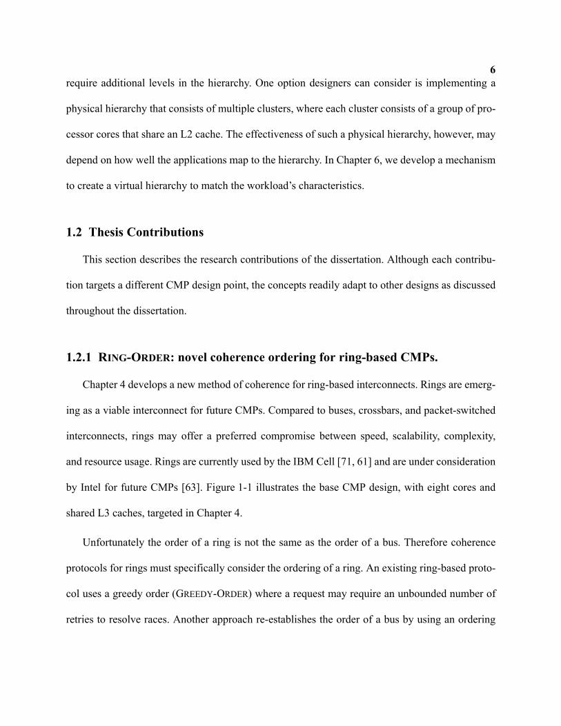
Chapter 4 develops a new method of coherence for ring-based interconnects. Rings are emerg-
ing as a viable interconnect for future CMPs. Compared to buses, crossbars, and packet-switched
interconnects, rings may offer a preferred compromise between speed, scalability, complexity,
and resource usage. Rings are currently used by the IBM Cell [71, 61] and are under consideration
by Intel for future CMPs [63]. Figure 1-1 illustrates the base CMP design, with eight cores and
shared L3 caches, targeted in Chapter 4.
Unfortunately the order of a ring is not the same as the order of a bus. Therefore coherence
protocols for rings must specifically consider the ordering of a ring. An existing ring-based proto-
col uses a greedy order (GREEDY-ORDER) where a request may require an unbounded number of
retries to resolve races. Another approach re-establishes the order of a bus by using an ordering
7
point. Alternatively a protocol that relies on no interconnect ordering, such as a directory-based
scheme, can deploy on a ring with considerable protocol overhead.
The primary contribution of Chapter 4 develops a new coherence protocol called RING-
ORDER. This scheme exploits the ordering properties of a ring by completing requests in the natu-
ral round-robin order. A secondary contribution demonstrates the use of an ordering point
(ORDERING-POINT) to re-establish a total bus order on a ring and compares it with RING-ORDER
and GREEDY-ORDER. We show that RING-ORDER performs up to 86% faster than ORDERING-
POINT and offers stable performance by never using retries.
1.2.2 Multiple-CMP Coherence: DirectoryCMP and TokenCMP
Chapter 5 considers coherence for systems comprised of multiple CMPs (Multiple-CMPs or
M-CMPs). M-CMP systems will require cache coherence both within a CMP and between CMPs.
One approach uses hierarchical coherence by combining an intra-CMP protocol for on-chip
coherence with an inter-CMP protocol for off-chip coherence. Unfortunately coupling two proto-
memory controller
Shared L3
Shared L3
Pri
va
te
L2
L1D$
L1I $
P0
memory controller
Pri
va
te
L2
L1D$
L1I $
P1
Pri
va
te
L2
L1D$
L1I $
P2P
riva
te
L2
L1D$
L1I $
P3
Priv
ate
L2
L1D$
L1I $
P7
Priv
ate
L2
L1D$
L1I $
P6
Priv
ate
L2
L1D$
L1I $
P5P
riva
te
L2
L1D$
L1I $
P4
FIGURE 1-1. Base CMP design for ring-based coherence in Chapter 4
8
cols together greatly increases complexity. Another approach completely ignores the hierarchy of
an M-CMP system by using a protocol that makes no distinction between an on- and off-chip
cache. Although applying existing, flat protocols to an M-CMP can offer correct function, perfor-
mance will suffer because the physical hierarchy is not exploited for lower latency and bandwidth.
The primary contribution of Chapter 5 develops the TokenCMP framework for M-CMP
coherence. TokenCMP extends token coherence [93] to make the system flat for correctness. The
flat correctness substrate greatly eases complexity and allows the successful model-checking of
the system. We then develop simple broadcast-based performance policies to exploit the physical
hierarchy in the common case.
A secondary contribution develops a detailed specification of a protocol, DirectoryCMP, that
uses directories for both intra-CMP and inter-CMP coherence. This two-level directory approach
gives considerable scalability to the system, but comes with a high level of complexity due to var-
ious races possible between the protocols. We solve the problem of races by using blocking direc-
P0 P1 P2 P3
L2 L2 L2 L2
me
mo
ryco
ntr
olle
rcrossbar
off-chip interface
L1 I&D L1 I&D L1 I&D L1 I&D
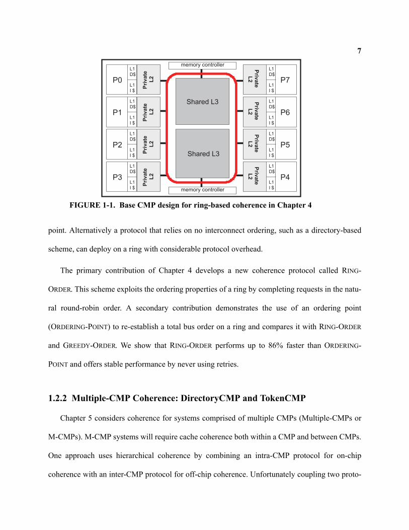
FIGURE 1-2. Base CMP Design for Chapter 5 on Multiple-CMP coherence.
9tories with an algorithm for avoiding deadlock between dependent directories. Both
DirectoryCMP and TokenCMP operate on completely unordered interconnects.
Chapter 5 primarily evaluates TokenCMP and DirectoryCMP in an M-CMP configuration
shown in Figure 1-2. Although the number of cores in this target design is modest, the techniques
we propose in Chapter 5 will generalize to slightly larger systems. We assume no interconnect
ordering for either the on-chip and off-chip interconnection networks to ensure our schemes scale
to increasing cores-per-CMP and CMPs. In addition to reducing complexity, we also show that
TokenCMP can perform up to 32% faster than DirectoryCMP.
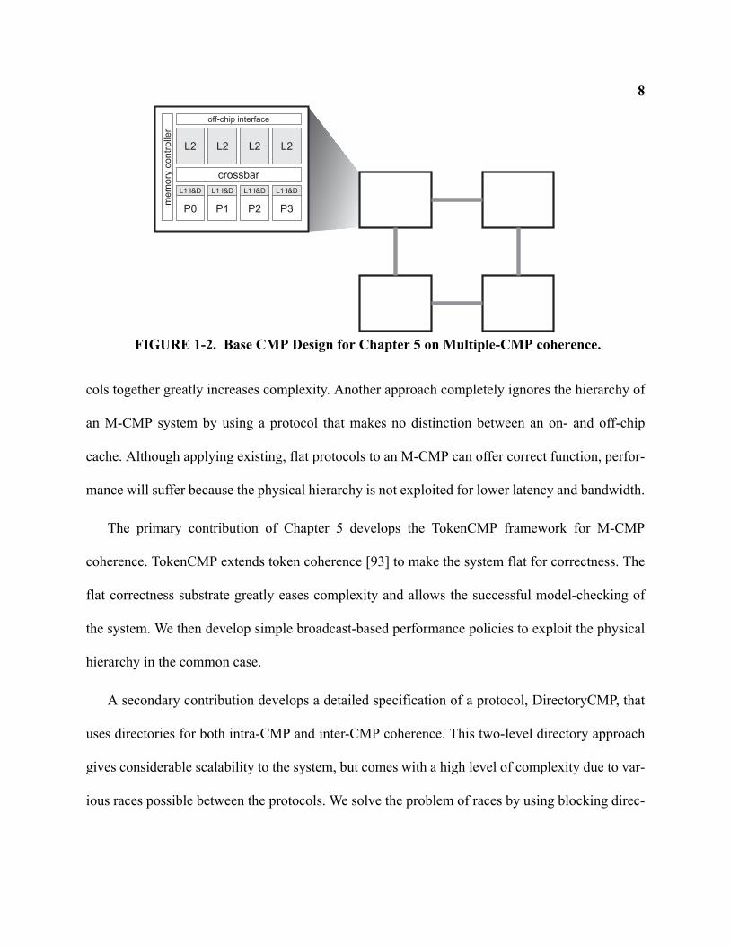
1.2.3 Virtual Hierarchies
Chapter 6 proposes the virtual hierarchy framework as a new way to build CMP memory sys-
tems. In a virtual hierarchy (VH), we overlay a coherence and cache hierarchy onto a fixed physi-
cal system. Unlike a physical hierarchy, a virtual hierarchy can adapt to fit how workloads are
space-shared for improved performance and performance isolation.
Chapter 6 applies a virtual hierarchy to a case study of a many-core CMP running several con-
solidated multithreaded workloads with space-sharing of on-chip resources. With the large num-
ber of threads available in future CMPs, consolidating workloads onto a single machine will
become more prevalent. Yet proposed memory systems for future CMPs do not target space-
shared workload consolidation.
The primary contribution we make develops a two-level virtual hierarchy on a physically-flat
CMP that harmonizes with workload assignment. A virtual hierarchy fulfills our goals of perfor-
mance, performance stability, and globally-shared memory to support dynamic reconfiguration
10
and content-based page sharing. To implement a virtual hierarchy, we develop two protocols:
VHDir-Dir and VHDir-Bcast. VHDir-Dir is an extension of DirectoryCMP, using fully mapped direc-
tories at both levels, to create a virtual hierarchy. VHDir-Bcast uses the same first-level protocol as
VHDir-Dir, but reduces global memory state by instead using a token-based broadcast protocol at
the second level. Compared to flat directory schemes, we show that VH protocols offer superior
performance and performance isolation when running consolidated workloads. In particular,
VHDir-Dir improves performance by up to 45% compared to the best-performing baseline proto-
col.
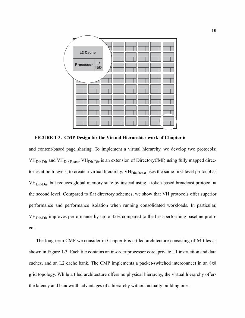
The long-term CMP we consider in Chapter 6 is a tiled architecture consisting of 64 tiles as
shown in Figure 1-3. Each tile contains an in-order processor core, private L1 instruction and data
caches, and an L2 cache bank. The CMP implements a packet-switched interconnect in an 8x8
grid topology. While a tiled architecture offers no physical hierarchy, the virtual hierarchy offers
the latency and bandwidth advantages of a hierarchy without actually building one.
Processor
L2 Cache
L1
I&D
FIGURE 1-3. CMP Design for the Virtual Hierarchies work of Chapter 6
111.2.4 Relationship to My Previously Published Work
This dissertation encompasses work that previously appeared in three conference publica-
tions. The work on ring-based cache coherence appears in the proceedings of the 39th Interna-
tional Symposium on Microarchitecture [96], co-authored with Mark Hill. Chapter 4 describes the
work in more detail and considers additional issues not addressed in the paper. The evaluation in
this dissertation also assumes better cache snooping capabilities and performs additional sensitiv-
ity analysis to ring and CMP parameters.
The work on TokenCMP work was previously published in the proceedings of the 11th annual
High-Performance Computer Architecture conference [95], with co-authors include Jesse D.
Bingham, Alan J. Hu, Milo M. Martin, Mark D. Hill and David A. Wood. Chapter 5 includes
more description and specification of DirectoryCMP, more qualitative complexity arguments for
TokenCMP, an additional TokenCMP performance protocol, and an updated evaluation with more
sensitivity analysis. However Chapter 5 does not include the paper’s model checking results
because it was performed by other co-authors.
The work on Virtual Hierarchies is published, with co-author Mark Hill, in the proceedings of
the 34th International Symposium on Computer Architecture [97] as well as the 2008 edition of
IEEE Micro’s Top Picks [98]. Chapter 6 changes some naming conventions, adds detail to proto-
col descriptions, and contains some minor evaluation differences.
1.3 Dissertation Structure
Chapter 2 presents a background on the cache coherence problem and an overview of prior
solutions for SMPs. We also discuss differences when considering coherence for CMPs. Chapter
123 discusses the tools, methodology, and workloads used for evaluation. Chapter 4 presents our
work on ring-based cache coherence protocols. Chapter 5 develops hierarchical coherence for M-
CMP systems. Chapter 6 presents the work on virtual hierarchies. Finally, Chapter 7 concludes
and offers reflections on the research.
13Chapter 2
Background: Cache Coherence
This chapter presents an overview of the cache coherence problem and some related work on
existing techniques. The scope and the amount of related work is large, so we focus on the aspects
most fundamental and related to the research in this dissertation. Section 2.1 develops the cache
coherence problem in terms of multiprocessor memory consistency. Section 2.2 presents back-
ground on existing coherence techniques developed for prior multiprocessors. Section 2.3 consid-
ers some existing hierarchical systems. In Section 2.4, we discuss some of the impacts that
emerging CMP-based multiprocessors have on the cache coherence problem.
2.1 Multiprocessor Memory Consistency
2.1.1 Overview
Serial programs running on von Neumann machines present a simple intuitive model to the
programmer. Instructions appear to execute in the order specified by the programmer or compiler
regardless if the implementation of the machine actually executes them in a different order.
Importantly, a program’s load returns the last value written to the memory location. Likewise a
store to a memory location determines the value of the next load. This definition leads to straight-
forward implementations and semantics for programs running on a single uniprocessor.
14Multithreaded programs running on multiprocessor machines complicate both the program-
ming model and the implementation to enforce a given model. In particular, the value returned by
a given load is not clear because the most recent store may have occurred on a different processor
core1. Thus architects define memory consistency models [3] to specify how a processor core can
observe memory accesses from other processor cores in the system.
Sequential consistency is a model defined such that the result of any execution is the same as
if the operations of all processors were executed in some sequential order, and the operations of
each individual processor appear in this sequence in the order specified by its program [83].
Other, more relaxed consistency models [3] can give the system builder more flexibility in imple-
menting optimizations to reduce memory latency. For example, a relaxed memory model makes it
straightforward to implement write buffers with bypassing.
While relaxed models can improve performance by retiring memory instructions before they
have been observed by other processors in the system, proper synchronization of multithreaded
programs is still required. Systems using a relaxed memory consistency model either include
additional instructions that allow a programmer to enforce orderings between loads and stores
[49], or define semantics such that a programmer can synchronize using carefully constructed
sequences of loads and stores.
Regardless of sequential or relaxed consistency, the addition of cache memories impacts how
consistency is implemented.
1. This chapter on background material will use the term “processor” to refer to a single processing element and its private cache
hierarchy. Terminology in the multicore era is evolving to use the term “processor” to refer to an entire chip that consists of
multiple “processor cores” or just “cores”. Future chapters will adhere to this new terminology by using the term “core” instead
of “processor” when referring to a single processing element. “Multiprocessors” will refer to systems that contain several cores,
including multicore and prior systems constructed of single-core chips.
152.1.2 Impact of Caches on Memory Consistency
Cache memories have been paramount in facilitating the rapid performance progress of
microprocessors over the past twenty years. They allow processor speeds to increase at a greater
rate than DRAM speeds by exploiting locality in memory accesses. The beauty of caches is their
effective operation with very little impact on the programmer or compiler. In other words, details
of the cache hierarchy do not affect the instruction set architecture and their operation is all hard-
ware-based and automatic from a programmer’s point-of-view.
While implementing a cache hierarchy had little ramification on a uniprocessor’s memory
consistency, caches complicate multiprocessor memory consistency. The root of the problem lies
in store propagation. While two processors in a system, P1 and P2, may both load the same mem-
ory block into their respective private caches, a subsequent store by either of the processors would
cause the values in the caches to differ. Thus if P1 stores to a memory block present in both the
caches of P1 and P2, P2’s cache holds a potentially stale value because of P1’s default operation
of storing to its own cache. This cache incoherence would not be problematic if P2 never again
loads to the block while still cached or if the multiprocessor did not support the transparent
shared-memory abstraction. But since the point of multiprocessor memory models is to support
shared-memory programming, at some point future loads of the block by P2 must receive the new
valued stored by P1, as defined by the model. That is, P1’s store must potentially affect the status
of the cache line in P2’s cache to maintain consistency, and the mechanisms for doing so are
defined as cache coherence.
A system is cache coherent if the execution results in a valid ordering of reads and writes to a
memory location. One valid ordering is a total order of all reads and writes to a location such that
16the value returned by each read operation is the value written by the last write to that location.
More formally, a read of address A by processor P1 (ReadP1 A) is ordered after a write of address
A by processor P2 (WriteP2 A) if the value received by (ReadP1 A) is the value written by
(WriteP2 A) or some other write to A ordered between (WriteP2 A) and (ReadP1 A). In a cache
coherent memory system, any write must be totally ordered with respect to other writes and reads
to the same location. However a common optimization allows a partial ordering of reads to a loca-
tion such that at any time in the system, either a single writer may exist or multiple readers (but
not both). An important implication of this definition, known as write serialization, is that all
writes to a location are seen in the same order to all processors.
Cache coherence is an important, but incomplete piece of multiprocessor memory consis-
tency. The mechanisms and protocols to implement cache coherence typically do so at a block (or
line) granularity such that interactions between different cache blocks are mostly independent.
Further mechanisms, usually implemented in the processor’s load and store unit, complete the
consistency model implementation by enforcing when various loads and stores to different blocks
can retire. Nonetheless, to enforce ordering requirements of a given consistency model, it is the
responsibility of the coherence protocol to indicate when a load or store operation to a block com-
pletes. Thus the strategy of this dissertation treats cache coherence as an independent issue of
memory consistency that is necessary but not sufficient to implement a given model. All the pro-
tocols we discuss can support any memory consistency model, but our descriptions will assume
sequential consistency.
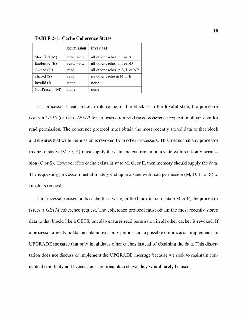
172.1.3 Cache Coherence Invariant and Permissions
A commonly used approach to cache coherence encodes a permission to each block stored in
a processor’s cache. Before a processor completes a load or a store, it must hit in the cache and the
cache must hold the appropriate permission for that block. If a processor stores to a block that is
cached by other processors, it must acquire store permission by revoking read permission from
other caches. This type of protocol is called an invalidation-based approach which maintains the
following invariant for a given cache block:
At any point in logical time, the permissions for a cache block can allow either a single writer
or multiple readers.
Permissions in a cache are reflected by a coherence state stored in the cache tag for a block.
States used by most existing cache coherence protocols are typically a subset of those in Table 2-
1 [128]. The coherence protocol ensures the invariants of the states are maintained. For example,
a processor can write to a block if the state is M or E because the coherence protocol ensures that
all other copies of the block in other caches are in state I. A processor can read the block when the
cache state is one of {M, E, O, S}. The cache coherence protocol enforces the coherence invariant
through state machines at each cache controller and by exchanging messages between controllers.
States M, S, and I represent the minimum set that allow multiple processors to simultaneously
hold read permission for a block (in State S), or to denote that a single processor holds write per-
mission (State M). State O and E are used to implement coherence protocol optimizations. For
example, State O helps the protocol satisfy a read request by accessing the cache of another pro-
cessor (the owner) instead of accessing slower DRAM. State E optimizes for unshared data by
giving a processor implicit write permission on a read miss.
18
If a processor’s read misses in its cache, or the block is in the Invalid state, the processor
issues a GETS (or GET_INSTR for an instruction read miss) coherence request to obtain data for
read permission. The coherence protocol must obtain the most recently stored data to that block
and ensures that write permission is revoked from other processors. This means that any processor
in one of states {M, O, E} must supply the data and can remain in a state with read-only permis-
sion (O or S). However if no cache exists in state M, O, or E, then memory should supply the data.
The requesting processor must ultimately end up in a state with read permission (M, O, E, or S) to
finish its request.
If a processor misses in its cache for a write, or the block is not in state M or E, the processor
issues a GETM coherence request. The coherence protocol must obtain the most recently stored
data to that block, like a GETS, but also ensures read permission in all other caches is revoked. If
a processor already holds the data in read-only permission, a possible optimization implements an
UPGRADE message that only invalidates other caches instead of obtaining the data. This disser-
tation does not discuss or implement the UPGRADE message because we seek to maintain con-
ceptual simplicity and because our empirical data shows they would rarely be used.
TABLE 2-1. Cache Coherence States
permission invariant
Modified (M) read, write all other caches in I or NPExclusive (E) read, write all other caches in I or NPOwned (O) read all other caches in S, I, or NPShared (S) read no other cache in M or EInvalid (I) none noneNot Present (NP) none none
19Satisfying a processor’s GETS or GETM request requires several mechanisms of the cache
coherence protocol to obtain the appropriate data and coherence permission. Many of these mech-
anisms are listed below:
• GETS messages must reach the processor in state M, E, or O, if one exists, to obtain the most-
recently written value.
• GETM message must reach all processors in state M, O, E, S.
• The protocol must provide indication to the processor when its GETM request can assume all
other processors have invalidated their caches.
• A processor must eventually succeed in completing its GETS or GETM operation. This prop-
erty is also referred to as the liveness of the processor, or as a system that prevents starvation
of a processor.
• The protocol must determine when memory responds. While cache tags can be augmented to
indicate a coherence state, doing so for standard DRAM chips is a significant compromise.
• The protocol must ensure the coherence invariant in the face of other concurrent requests for
the same block. This problem is exacerbated by unordered interconnects that can induce many
race conditions (or races). A coherence race occurs when the timing of one request can inter-
act with another concurrent request.
• The protocol must correctly replace dirty data to DRAM.
Before we further discuss invalidate-based coherence protocols, we briefly touch upon an
alternative approach to coherence. An alternative to revoking coherence permission from caches
is to update the values of other caches on any store if they hold the block. Examples of update
protocols include the Xerox Dragon [16] and DEC Firefly [133]. While update protocols immedi-
20ately propagate the most recent store value to all other caches holding the block, the main disad-
vantages are the amount of bandwidth consumed and the difficulty in preserving write
serialization. In particular, when a processor stores to a block multiple times before another pro-
cessor reads the block, all updates except for the most recent were unnecessary. And when two
processors attempt to update a value simultaneously, achieving atomicity of a single write with
respect to another can become challenging. For these reasons, most systems implement invali-
date-based coherence.
2.2 Cache Coherence Techniques for SMP and ccNUMA Machines
This section presents background work on cache coherence protocols for a large class of prior
shared-memory multiprocessor machines. Prior multiprocessors were generally classified as sym-
metric multiprocessors (SMPs) or cache-coherent non-uniform memory access multiprocessors
(ccNUMA). SMP machines generally offered the same memory access latency to all processors
across the entire address space. On the other hand, ccNUMA machines exhibited different access
latencies depending on memory region and the physical location of a processor.
Sections 2.2.1 through 2.2.4 present snooping protocols. We consider snooping protocols as
those that broadcast a coherence request to all nodes such that distributed algorithms and state
machines can implement the cache coherence protocol. In these systems, a node is considered a
uniprocessor with its private cache hierarchy. In Section 2.2.5, we present the background on
directory-based systems. Finally in Section 2.2.6, we review an approach to coherence called
token coherence proposed in 2003.
21
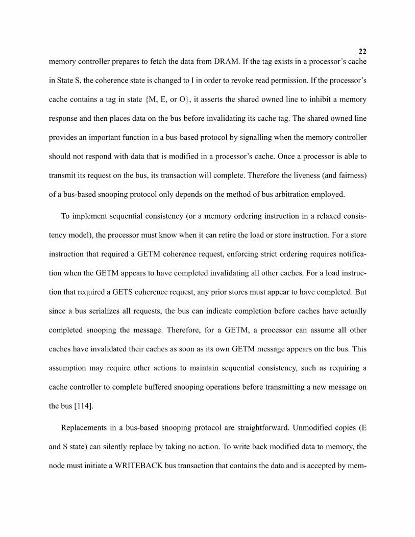
2.2.1 Snooping on a Bus
The first widely-adopted approach to cache coherence is snooping on a bus. A bus connects
all components to an electrical, or logical, set of wires. A bus provides key ordering and atomicity
properties that enable straightforward coherence operations. First, all endpoints on a bus observe
transmitted messages in the same total order. Second, buses provide atomicity such that only one
message can appear on the bus at a time and that all endpoints observe the message. Third, buses
implement shared lines that allow any endpoint to manipulate a signal or condition that is globally
visible to all other endpoints during a bus transaction. Shared lines facilitate both bus arbitration
and cache coherence operations. For example, a shared owner line can indicate if any processor is
in State O, and a shared sharer line can indicate if any processor is in State S.
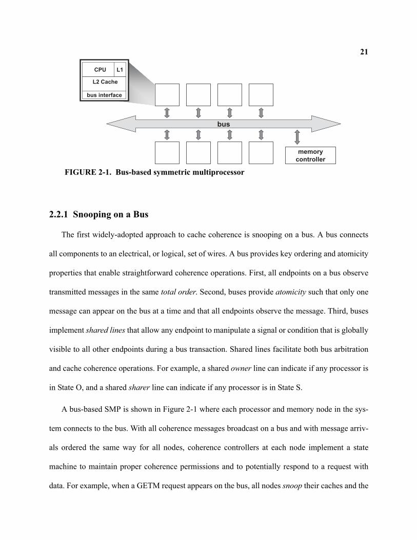
A bus-based SMP is shown in Figure 2-1 where each processor and memory node in the sys-
tem connects to the bus. With all coherence messages broadcast on a bus and with message arriv-
als ordered the same way for all nodes, coherence controllers at each node implement a state
machine to maintain proper coherence permissions and to potentially respond to a request with
data. For example, when a GETM request appears on the bus, all nodes snoop their caches and the
bus
L2 Cache
CPU L1
memory
controller
bus interface
FIGURE 2-1. Bus-based symmetric multiprocessor
22memory controller prepares to fetch the data from DRAM. If the tag exists in a processor’s cache
in State S, the coherence state is changed to I in order to revoke read permission. If the processor’s
cache contains a tag in state {M, E, or O}, it asserts the shared owned line to inhibit a memory
response and then places data on the bus before invalidating its cache tag. The shared owned line
provides an important function in a bus-based protocol by signalling when the memory controller
should not respond with data that is modified in a processor’s cache. Once a processor is able to
transmit its request on the bus, its transaction will complete. Therefore the liveness (and fairness)
of a bus-based snooping protocol only depends on the method of bus arbitration employed.
To implement sequential consistency (or a memory ordering instruction in a relaxed consis-
tency model), the processor must know when it can retire the load or store instruction. For a store
instruction that required a GETM coherence request, enforcing strict ordering requires notifica-
tion when the GETM appears to have completed invalidating all other caches. For a load instruc-
tion that required a GETS coherence request, any prior stores must appear to have completed. But
since a bus serializes all requests, the bus can indicate completion before caches have actually
completed snooping the message. Therefore, for a GETM, a processor can assume all other
caches have invalidated their caches as soon as its own GETM message appears on the bus. This
assumption may require other actions to maintain sequential consistency, such as requiring a
cache controller to complete buffered snooping operations before transmitting a new message on
the bus [114].
Replacements in a bus-based snooping protocol are straightforward. Unmodified copies (E
and S state) can silently replace by taking no action. To write back modified data to memory, the
node must initiate a WRITEBACK bus transaction that contains the data and is accepted by mem-
23ory. The atomic nature of the bus ensures that racing coherence requests are ordered with respect
to the writeback operation.
Snooping coherence on a bus was first described by Goodman [50]. Early bus implementa-
tions used electrically shared wires that held the bus for an entire coherence transaction. Higher-
performing buses used split transactions to allow other processors to acquire the bus while wait-
ing for a response. More modern snooping systems implement a logical bus using additional
switches, state, and logic rather than shared electrical wires. Furthermore, they can also imple-
ment the ordering of a bus only for coherence control messages. For example, the Sun Starfire
[30] system implements a logical bus only for coherence request messages, but data responses
travel on a different switched interconnect. Even higher-performing buses use pipelining tech-
niques to achieve more concurrency. While these more aggressive buses may relax the atomicity
property, they still provide a total order of coherence requests that enables a straightforward
implementation of snooping like described in this section.
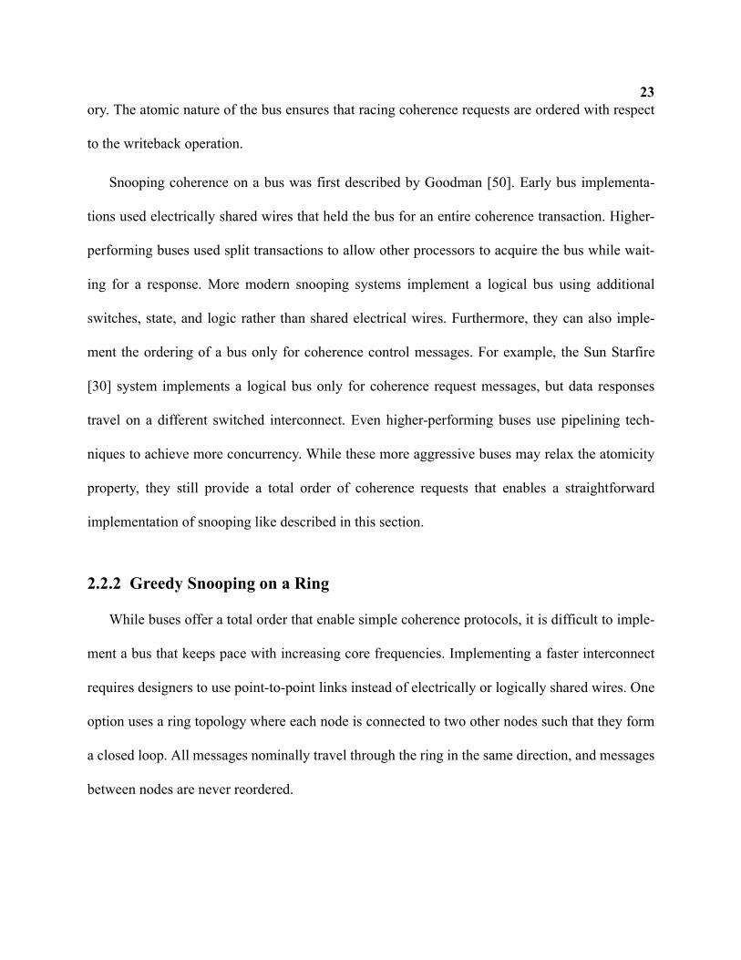
2.2.2 Greedy Snooping on a Ring
While buses offer a total order that enable simple coherence protocols, it is difficult to imple-
ment a bus that keeps pace with increasing core frequencies. Implementing a faster interconnect
requires designers to use point-to-point links instead of electrically or logically shared wires. One
option uses a ring topology where each node is connected to two other nodes such that they form
a closed loop. All messages nominally travel through the ring in the same direction, and messages
between nodes are never reordered.
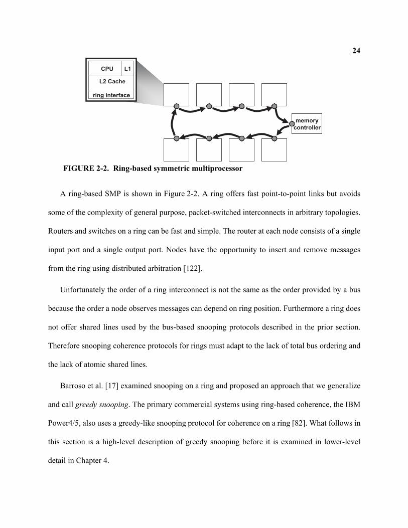
24
A ring-based SMP is shown in Figure 2-2. A ring offers fast point-to-point links but avoids
some of the complexity of general purpose, packet-switched interconnects in arbitrary topologies.
Routers and switches on a ring can be fast and simple. The router at each node consists of a single
input port and a single output port. Nodes have the opportunity to insert and remove messages
from the ring using distributed arbitration [122].
Unfortunately the order of a ring interconnect is not the same as the order provided by a bus
because the order a node observes messages can depend on ring position. Furthermore a ring does
not offer shared lines used by the bus-based snooping protocols described in the prior section.
Therefore snooping coherence protocols for rings must adapt to the lack of total bus ordering and
the lack of atomic shared lines.
Barroso et al. [17] examined snooping on a ring and proposed an approach that we generalize
and call greedy snooping. The primary commercial systems using ring-based coherence, the IBM
Power4/5, also uses a greedy-like snooping protocol for coherence on a ring [82]. What follows in
this section is a high-level description of greedy snooping before it is examined in lower-level
detail in Chapter 4.
L2 Cache
CPU L1
memory
controller
ring interface
FIGURE 2-2. Ring-based symmetric multiprocessor
25A greedy snooping protocol broadcasts coherence requests to all other nodes in the system. A
GETS request seeks to find the owner of the cache line to obtain data, which is the cache in state
O, E, or M. A GETM request additionally seeks to invalidate all other sharers. While a ring natu-
rally accomplishes the broadcast operation, there is no total ordering or atomicity. Therefore
unlike the bus protocol of the previous section, a requestor cannot be assured that its coherence
request is ordered once the message is transmitted and racing (or conflicting) coherence requests
must be handled differently.
First, all processors in a greedy protocol send the result of the snoop operation to the requestor
to indicate when a request successfully completes. This snoop response message indicates if the
processor cached the block, invalidated its cache on a GETM request, and if it was the owner and
will respond with data. The snoop response itself does not contain data and instead indicates
acknowledgement (ACK) of processing a coherence request. Fortunately a ring can reduce the
cost of a snoop response from every processor by combining responses into a single message (or
field) as a message traverses the ring.
Second, the lack of bus ordering means the greedy protocol must handle racing requests to
ensure correct coherence. With no total ordering, racing coherence requests for the same block
address greedily order based on which request reaches the owning processor first. The owning
processor acknowledges the winning request and proceeds to handle it by sending data and/or
transferring ownership. Other racing (or conflicting) requests for the same block address are
forced to retry their request by re-issuing the request message on the interconnect. Processors
retry their request when the snoop response messages indicate that the request message was not
acknowledged by the owner. Because of this greedy order, some requestors may issue an
26unbounded number of retries due to pathological behavior that may continually cause a request to
lose the race to the owner. Therefore, a greedy protocol may exhibit liveness issues without addi-
tional mechanisms.
A greedy protocol on a ring also requires additional mechanisms to interface with memory. In
a bus-based system, the memory controller responds to a GETS or GETM request if not inhibited
by the shared owner line. Without shared lines, either memory must contain additional state to
determine if it should source the data, or the requestor must explicitly request data from memory
if it discovers there is no other cache that owns the block.
Like bus-based snooping protocols, replacement operations with a greedily-ordered snooping
protocol are straightforward. Unmodified shared copies can silently replace whereas modified
data is simply placed on the ring for writeback to memory. Races between a replacing node and a
requesting node will result in the requestor issuing a retry.
Additional details of how a greedy protocol operates in a ring topology are deferred to Chap-
ter 4, where we consider ring-based coherence in more detail.
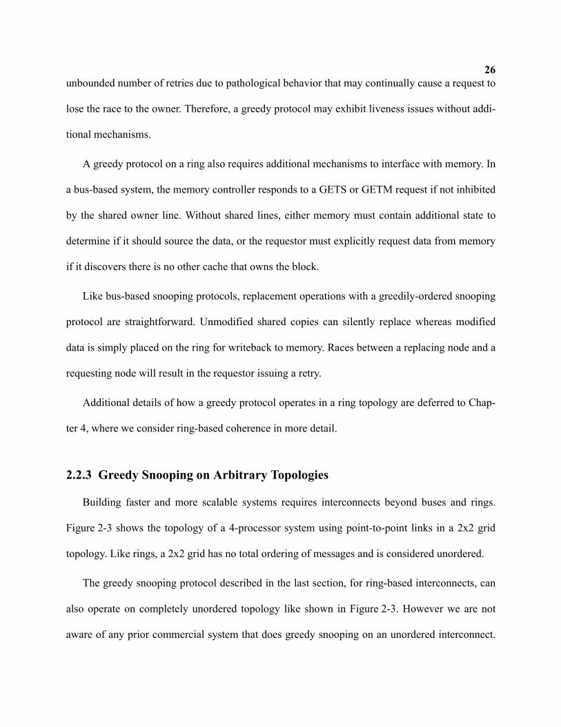
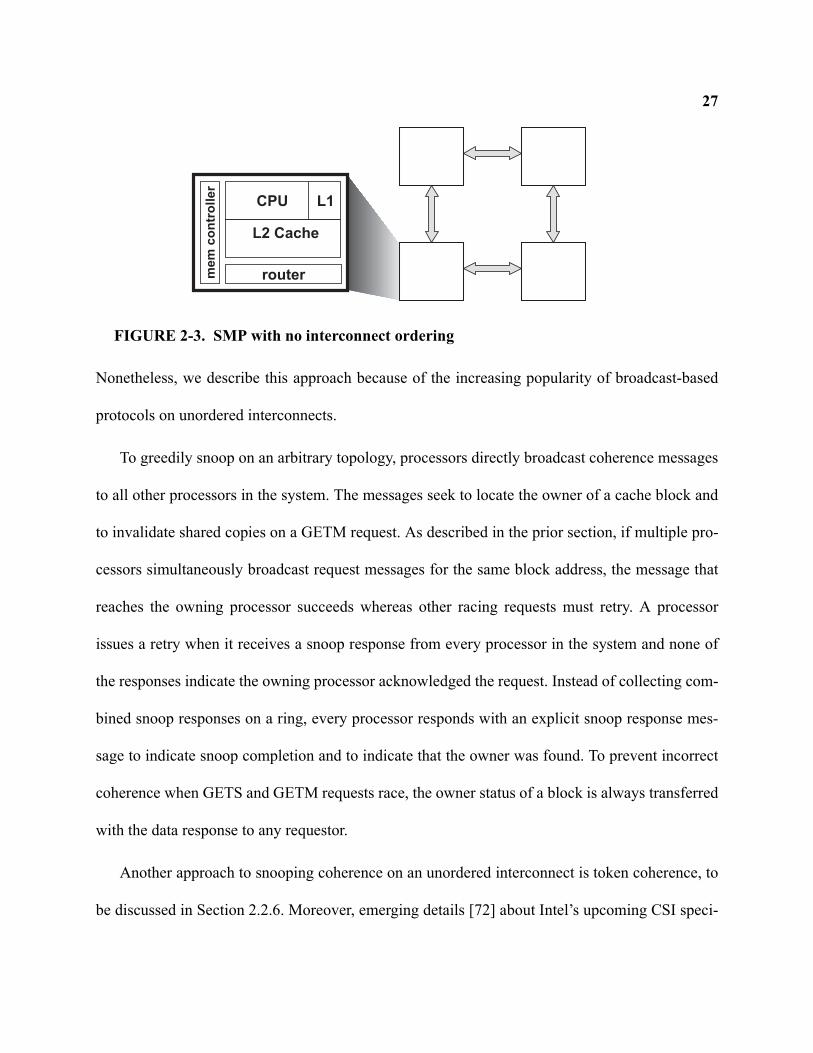
2.2.3 Greedy Snooping on Arbitrary Topologies
Building faster and more scalable systems requires interconnects beyond buses and rings.
Figure 2-3 shows the topology of a 4-processor system using point-to-point links in a 2x2 grid
topology. Like rings, a 2x2 grid has no total ordering of messages and is considered unordered.
The greedy snooping protocol described in the last section, for ring-based interconnects, can
also operate on completely unordered topology like shown in Figure 2-3. However we are not
aware of any prior commercial system that does greedy snooping on an unordered interconnect.
27
Nonetheless, we describe this approach because of the increasing popularity of broadcast-based
protocols on unordered interconnects.
To greedily snoop on an arbitrary topology, processors directly broadcast coherence messages
to all other processors in the system. The messages seek to locate the owner of a cache block and
to invalidate shared copies on a GETM request. As described in the prior section, if multiple pro-
cessors simultaneously broadcast request messages for the same block address, the message that
reaches the owning processor succeeds whereas other racing requests must retry. A processor
issues a retry when it receives a snoop response from every processor in the system and none of
the responses indicate the owning processor acknowledged the request. Instead of collecting com-
bined snoop responses on a ring, every processor responds with an explicit snoop response mes-
sage to indicate snoop completion and to indicate that the owner was found. To prevent incorrect
coherence when GETS and GETM requests race, the owner status of a block is always transferred
with the data response to any requestor.
Another approach to snooping coherence on an unordered interconnect is token coherence, to
be discussed in Section 2.2.6. Moreover, emerging details [72] about Intel’s upcoming CSI speci-
routermem
co
ntr
oll
er
L2 Cache
CPU L1
FIGURE 2-3. SMP with no interconnect ordering
28fication indicate that unordered broadcast coherence is also used along with a Forwarding (F)
state that appears similar to greedy snooping’s required owner (O) state. However they suggest
conflict is explicitly detected and resolved by an ordering point instead of using retries. At this
time and to our knowledge, no additional details are published about their protocol. The following
section discusses a protocol that always uses an ordering point to avoid races and conflict.
2.2.4 Ordered Snooping on Arbitrary Topologies
It is often said that all problems in computer science can be solved with a level of indirection.
We now describe a protocol, based on the AMD Opteron [7], that adds a level of indirection to
achieve coherence ordering on an unordered interconnect without the use of retries. A processor
first sends its coherence request message to an ordering point to establish the total order. In the
Opteron system, the memory controller functions as the ordering point. The ordering point then
broadcasts the request message to all other processors in the system. The ordering point also
blocks on that address to prevent subsequent coherence requests for the same cache line to race
with a request in progress.
To indicate completion of a read or write, the requestor must wait for an explicit acknowl-
edgement (ACK) message from every other processor in the system after they complete their
snoops. Once the requestor has received all acknowledgements and data, it unblocks the memory
controller by sending a completion message. The memory controller can then initiate a broadcast
for the next waiting request for that block. Since the memory controller fully buffers and orders
requests, there are no inherent liveness or starvation issues with the protocol itself.
Once again, the lack of shared lines requires a mechanism to fetch data from DRAM when no
other processor caches the block. One option is for memory to respond with data on any GETS
29and GETM request. However if a cache holds a dirty copy of the line, then it too responds to the
requestor with the more recent data. Thus this approach results in two data responses on any shar-
ing between processors. Another option is for the requesting processor to re-request the data from
the memory controller once it receives a snoop response from every processor indicating no other
sharers. The memory controller can reduce the latency overhead of this approach by prefetching
the data from DRAM when it receives the initial GETS or GETM message. A third option, imple-
mented by Martin et al.’s adaptation of this protocol [90], adds an owner-bit to memory to indicate
that memory owns the block and should respond with data.
Unlike bus-based and greedy snooping protocols, replacing dirty data to memory requires
additional messaging to ensure coherence. For example, consider a processor P1 replacing dirty
data to memory. If a race occurs where P2 issues a request to the memory controller while the
dirty data from P1 is in-flight to memory, P2 could receive stale data from memory instead of P1’s
most-recently modified data. To solve this race, one solution requires P1 to enter a transient state
upon sending dirty data to memory. P1 also maintains a copy of data, while in the writeback tran-
sient state, to respond to subsequent requests until it receives an ACK message from the memory
controller. We refer to this type of replacement operation as a two-phase writeback. Another type
of writeback first requests permission with the memory controller to replace the block and then
sends data after receiving an acknowledgement. This is known as a three-phase writeback [54].
The primary disadvantage of the Opteron-like protocol is its excessive use of bandwidth for
broadcasts and snoop responses as the system size increases. The following section considers
another approach that uses an ordering point but that uses additional state to reduce bandwidth.
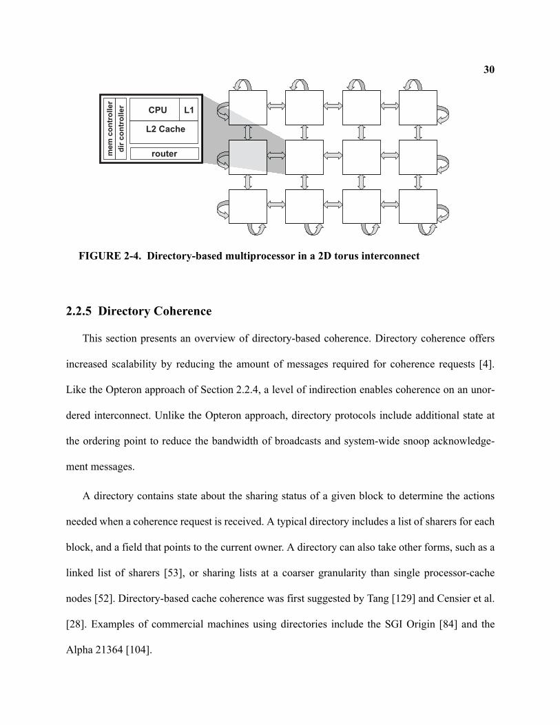
30
2.2.5 Directory Coherence
This section presents an overview of directory-based coherence. Directory coherence offers
increased scalability by reducing the amount of messages required for coherence requests [4].
Like the Opteron approach of Section 2.2.4, a level of indirection enables coherence on an unor-
dered interconnect. Unlike the Opteron approach, directory protocols include additional state at
the ordering point to reduce the bandwidth of broadcasts and system-wide snoop acknowledge-
ment messages.
A directory contains state about the sharing status of a given block to determine the actions
needed when a coherence request is received. A typical directory includes a list of sharers for each
block, and a field that points to the current owner. A directory can also take other forms, such as a
linked list of sharers [53], or sharing lists at a coarser granularity than single processor-cache
nodes [52]. Directory-based cache coherence was first suggested by Tang [129] and Censier et al.
[28]. Examples of commercial machines using directories include the SGI Origin [84] and the
Alpha 21364 [104].
routermem
co
ntr
oll
er
L2 Cache
CPU L1d
irc
on
tro
lle
r
FIGURE 2-4. Directory-based multiprocessor in a 2D torus interconnect
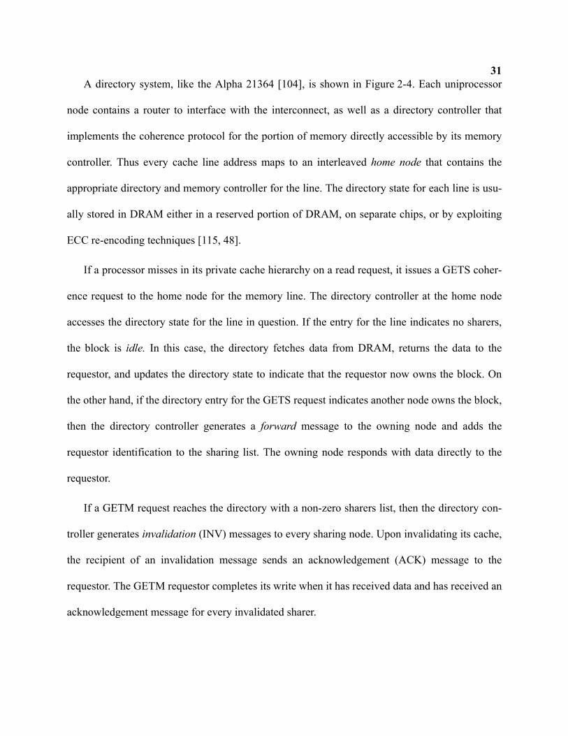
31A directory system, like the Alpha 21364 [104], is shown in Figure 2-4. Each uniprocessor
node contains a router to interface with the interconnect, as well as a directory controller that
implements the coherence protocol for the portion of memory directly accessible by its memory
controller. Thus every cache line address maps to an interleaved home node that contains the
appropriate directory and memory controller for the line. The directory state for each line is usu-
ally stored in DRAM either in a reserved portion of DRAM, on separate chips, or by exploiting
ECC re-encoding techniques [115, 48].
If a processor misses in its private cache hierarchy on a read request, it issues a GETS coher-
ence request to the home node for the memory line. The directory controller at the home node
accesses the directory state for the line in question. If the entry for the line indicates no sharers,
the block is idle. In this case, the directory fetches data from DRAM, returns the data to the
requestor, and updates the directory state to indicate that the requestor now owns the block. On
the other hand, if the directory entry for the GETS request indicates another node owns the block,
then the directory controller generates a forward message to the owning node and adds the
requestor identification to the sharing list. The owning node responds with data directly to the
requestor.
If a GETM request reaches the directory with a non-zero sharers list, then the directory con-
troller generates invalidation (INV) messages to every sharing node. Upon invalidating its cache,
the recipient of an invalidation message sends an acknowledgement (ACK) message to the
requestor. The GETM requestor completes its write when it has received data and has received an
acknowledgement message for every invalidated sharer.
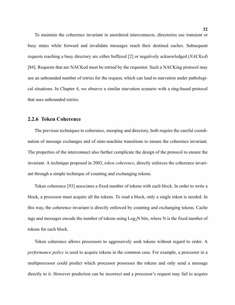
32To maintain the coherence invariant in unordered interconnects, directories use transient or
busy states while forward and invalidate messages reach their destined caches. Subsequent
requests reaching a busy directory are either buffered [2] or negatively acknowledged (NACKed)
[84]. Requests that are NACKed must be retried by the requestor. Such a NACKing protocol may
use an unbounded number of retries for the request, which can lead to starvation under pathologi-
cal situations. In Chapter 4, we observe a similar starvation scenario with a ring-based protocol
that uses unbounded retries.
2.2.6 Token Coherence
The previous techniques to coherence, snooping and directory, both require the careful coordi-
nation of message exchanges and of state-machine transitions to ensure the coherence invariant.
The properties of the interconnect also further complicate the design of the protocol to ensure the
invariant. A technique proposed in 2003, token coherence, directly enforces the coherence invari-
ant through a simple technique of counting and exchanging tokens.
Token coherence [93] associates a fixed number of tokens with each block. In order to write a
block, a processor must acquire all the tokens. To read a block, only a single token is needed. In
this way, the coherence invariant is directly enforced by counting and exchanging tokens. Cache
tags and messages encode the number of tokens using Log2N bits, where N is the fixed number of
tokens for each block.
Token coherence allows processors to aggressively seek tokens without regard to order. A
performance policy is used to acquire tokens in the common case. For example, a processor in a
multiprocessor could predict which processor possesses the tokens and only send a message
directly to it. However prediction can be incorrect and a processor’s request may fail to acquire
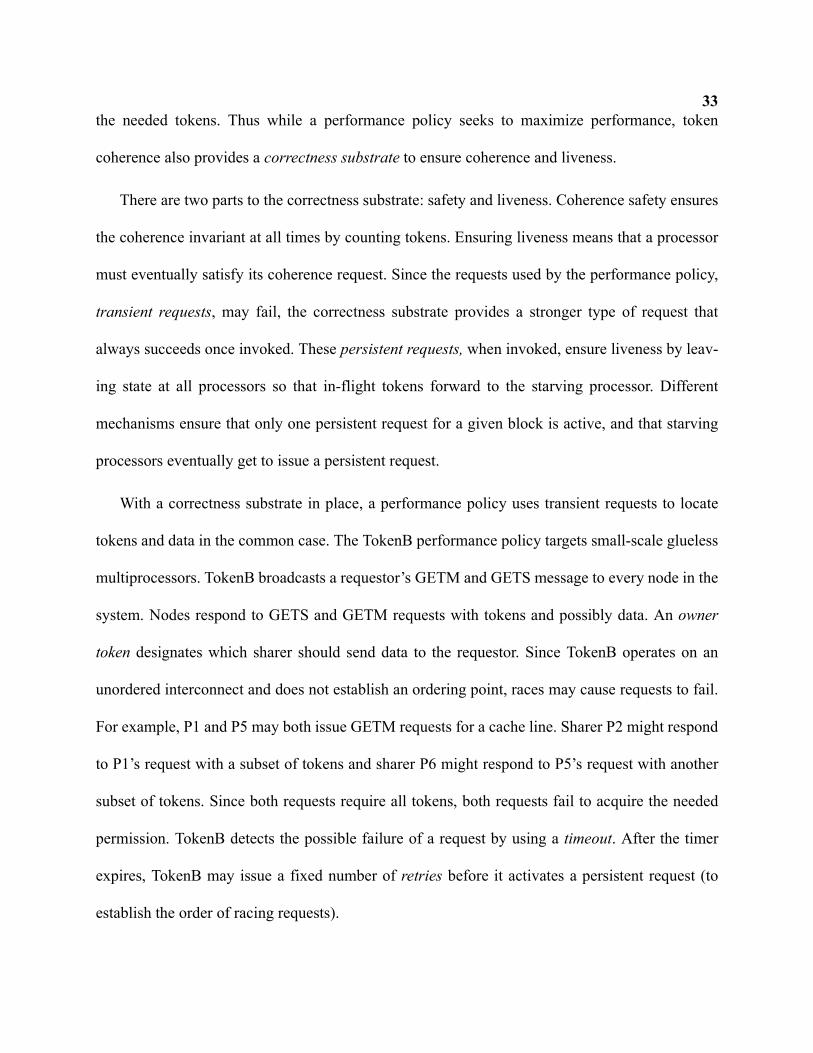
33the needed tokens. Thus while a performance policy seeks to maximize performance, token
coherence also provides a correctness substrate to ensure coherence and liveness.
There are two parts to the correctness substrate: safety and liveness. Coherence safety ensures
the coherence invariant at all times by counting tokens. Ensuring liveness means that a processor
must eventually satisfy its coherence request. Since the requests used by the performance policy,
transient requests, may fail, the correctness substrate provides a stronger type of request that
always succeeds once invoked. These persistent requests, when invoked, ensure liveness by leav-
ing state at all processors so that in-flight tokens forward to the starving processor. Different
mechanisms ensure that only one persistent request for a given block is active, and that starving
processors eventually get to issue a persistent request.
With a correctness substrate in place, a performance policy uses transient requests to locate
tokens and data in the common case. The TokenB performance policy targets small-scale glueless
multiprocessors. TokenB broadcasts a requestor’s GETM and GETS message to every node in the
system. Nodes respond to GETS and GETM requests with tokens and possibly data. An owner
token designates which sharer should send data to the requestor. Since TokenB operates on an
unordered interconnect and does not establish an ordering point, races may cause requests to fail.
For example, P1 and P5 may both issue GETM requests for a cache line. Sharer P2 might respond
to P1’s request with a subset of tokens and sharer P6 might respond to P5’s request with another
subset of tokens. Since both requests require all tokens, both requests fail to acquire the needed
permission. TokenB detects the possible failure of a request by using a timeout. After the timer
expires, TokenB may issue a fixed number of retries before it activates a persistent request (to
establish the order of racing requests).
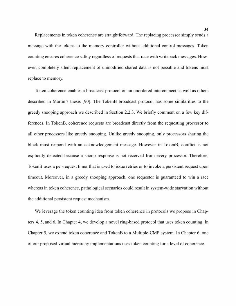
34Replacements in token coherence are straightforward. The replacing processor simply sends a
message with the tokens to the memory controller without additional control messages. Token
counting ensures coherence safety regardless of requests that race with writeback messages. How-
ever, completely silent replacement of unmodified shared data is not possible and tokens must
replace to memory.
Token coherence enables a broadcast protocol on an unordered interconnect as well as others
described in Martin’s thesis [90]. The TokenB broadcast protocol has some similarities to the
greedy snooping approach we described in Section 2.2.3. We briefly comment on a few key dif-
ferences. In TokenB, coherence requests are broadcast directly from the requesting processor to
all other processors like greedy snooping. Unlike greedy snooping, only processors sharing the
block must respond with an acknowledgement message. However in TokenB, conflict is not
explicitly detected because a snoop response is not received from every processor. Therefore,
TokenB uses a per-request timer that is used to issue retries or to invoke a persistent request upon
timeout. Moreover, in a greedy snooping approach, one requestor is guaranteed to win a race
whereas in token coherence, pathological scenarios could result in system-wide starvation without
the additional persistent request mechanism.
We leverage the token counting idea from token coherence in protocols we propose in Chap-
ters 4, 5, and 6. In Chapter 4, we develop a novel ring-based protocol that uses token counting. In
Chapter 5, we extend token coherence and TokenB to a Multiple-CMP system. In Chapter 6, one
of our proposed virtual hierarchy implementations uses token counting for a level of coherence.
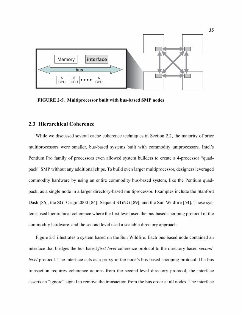
35
2.3 Hierarchical Coherence
While we discussed several cache coherence techniques in Section 2.2, the majority of prior
multiprocessors were smaller, bus-based systems built with commodity uniprocessors. Intel’s
Pentium Pro family of processors even allowed system builders to create a 4-processor “quad-
pack” SMP without any additional chips. To build even larger multiprocessor, designers leveraged
commodity hardware by using an entire commodity bus-based system, like the Pentium quad-
pack, as a single node in a larger directory-based multiprocessor. Examples include the Stanford
Dash [86], the SGI Origin2000 [84], Sequent STiNG [89], and the Sun Wildfire [54]. These sys-
tems used hierarchical coherence where the first level used the bus-based snooping protocol of the
commodity hardware, and the second level used a scalable directory approach.
Figure 2-5 illustrates a system based on the Sun Wildfire. Each bus-based node contained an
interface that bridges the bus-based first-level coherence protocol to the directory-based second-
level protocol. The interface acts as a proxy in the node’s bus-based snooping protocol. If a bus
transaction requires coherence actions from the second-level directory protocol, the interface
asserts an “ignore” signal to remove the transaction from the bus order at all nodes. The interface
Memory interface
$CPU
$CPU
$CPU
bus
FIGURE 2-5. Multiprocessor built with bus-based SMP nodes
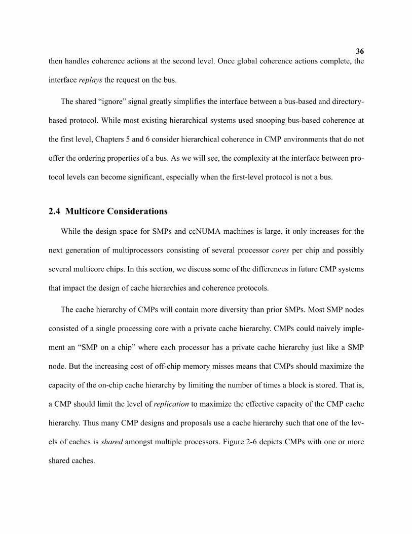
36then handles coherence actions at the second level. Once global coherence actions complete, the
interface replays the request on the bus.
The shared “ignore” signal greatly simplifies the interface between a bus-based and directory-
based protocol. While most existing hierarchical systems used snooping bus-based coherence at
the first level, Chapters 5 and 6 consider hierarchical coherence in CMP environments that do not
offer the ordering properties of a bus. As we will see, the complexity at the interface between pro-
tocol levels can become significant, especially when the first-level protocol is not a bus.
2.4 Multicore Considerations
While the design space for SMPs and ccNUMA machines is large, it only increases for the
next generation of multiprocessors consisting of several processor cores per chip and possibly
several multicore chips. In this section, we discuss some of the differences in future CMP systems
that impact the design of cache hierarchies and coherence protocols.
The cache hierarchy of CMPs will contain more diversity than prior SMPs. Most SMP nodes
consisted of a single processing core with a private cache hierarchy. CMPs could naively imple-
ment an “SMP on a chip” where each processor has a private cache hierarchy just like a SMP
node. But the increasing cost of off-chip memory misses means that CMPs should maximize the
capacity of the on-chip cache hierarchy by limiting the number of times a block is stored. That is,
a CMP should limit the level of replication to maximize the effective capacity of the CMP cache
hierarchy. Thus many CMP designs and proposals use a cache hierarchy such that one of the lev-
els of caches is shared amongst multiple processors. Figure 2-6 depicts CMPs with one or more
shared caches.
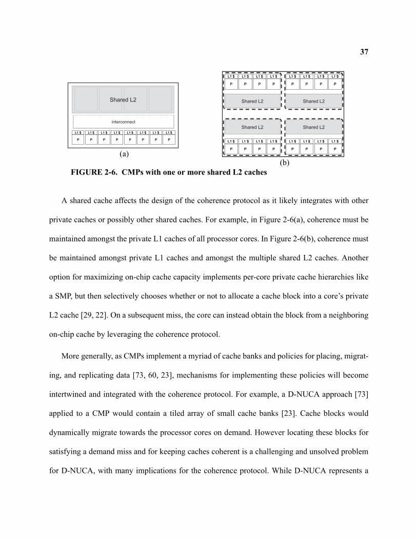
37
A shared cache affects the design of the coherence protocol as it likely integrates with other
private caches or possibly other shared caches. For example, in Figure 2-6(a), coherence must be
maintained amongst the private L1 caches of all processor cores. In Figure 2-6(b), coherence must
be maintained amongst private L1 caches and amongst the multiple shared L2 caches. Another
option for maximizing on-chip cache capacity implements per-core private cache hierarchies like
a SMP, but then selectively chooses whether or not to allocate a cache block into a core’s private
L2 cache [29, 22]. On a subsequent miss, the core can instead obtain the block from a neighboring
on-chip cache by leveraging the coherence protocol.
More generally, as CMPs implement a myriad of cache banks and policies for placing, migrat-
ing, and replicating data [73, 60, 23], mechanisms for implementing these policies will become
intertwined and integrated with the coherence protocol. For example, a D-NUCA approach [73]
applied to a CMP would contain a tiled array of small cache banks [23]. Cache blocks would
dynamically migrate towards the processor cores on demand. However locating these blocks for
satisfying a demand miss and for keeping caches coherent is a challenging and unsolved problem
for D-NUCA, with many implications for the coherence protocol. While D-NUCA represents a
P
L1 $
P
L1 $
P
L1 $
P
L1 $
P
L1 $
P
L1 $
P
L1 $
P
L1 $
P
L1 $
P
L1 $
P
L1 $
P
L1 $
P
L1 $
P
L1 $
P
L1 $
P
L1 $
Shared L2 Shared L2
P
L1 $
P
L1 $
P
L1 $
P
L1 $
P
L1 $
P
L1 $
P
L1 $
P
L1 $
P
L1 $
P
L1 $
P
L1 $
P
L1 $
P
L1 $
P
L1 $
P
L1 $
P
L1 $
Shared L2 Shared L2
P
L1 $
P
L1 $
P
L1 $
P
L1 $
P
L1 $
P
L1 $
P
L1 $
P
L1 $
P
L1 $
P
L1 $
P
L1 $
P
L1 $
P
L1 $
P
L1 $
P
L1 $
P
L1 $
Shared L2
interconnect
FIGURE 2-6. CMPs with one or more shared L2 caches
(a)(b)
38complex design, even simpler approaches will need coherence optimizations that recognize the
latency gap between on- and off-chip communication, and that respect distance locality by acquir-
ing data from the closest possible source.
Finally, the structure of CMPs, with their multiple private caches, provides new opportunities
to implement known techniques. For example, a directory protocol for on-chip coherence may
implement the directory state in SRAM instead of DRAM. Techniques for implementing on-chip
directory coherence will be discussed in Chapter 6.
39Chapter 3
Evaluation Methodology
This chapter presents the common evaluation methodology used for the dissertation.
3.1 Full-System Simulation Tools
We use full-system simulation to evaluate our proposed systems. Full-system simulation
enables us to evaluate proposed systems running realistic commercial workloads on top of actual
operating systems. It also captures the subtle timing affects not possible with trace-based evalua-
tion. For example, different coherence protocols might cause the execution to take different code
paths that would not be reflected in a trace.
We use the Wisconsin GEMS simulation environment [94], which is based on Virtutech
Simics [137]. Simics is a commercial product from Virtutech AB that provides a full-system func-
tional simulation of multiprocessor systems. GEMS is a set of modules that extends Simics with
timing fidelity for our modeled system. GEMS consists of two primary modules: Ruby and Opal.
Ruby models memory hierarchies and uses the SLICC domain-specific language to specify proto-
cols. Opal models the timing of an out-of-order SPARC processor.
3.2 Methods
Evaluating the performance of a proposed system requires meaningful metrics. While
researchers of microarchitectures often use instructions-per-cycle (IPC) as a metric to judge per-
40formance improvements, IPC is not a good metric for evaluating the coherence protocols and sys-
tems in this dissertation [10]. The reason is that the components studied are sensitive to
synchronization, where the rate of instructions completed is not a good indicator of system perfor-
mance. For example, spending more time on spin-based synchronization, common in OS kernels,
would lead to a higher and better IPC (because of excessive spinning) even though overall runt-
ime would increase. Instead, we evaluate overall performance by measuring the amount of work
completed by the system.
We use a transaction-counting methodology [8] to measure the performance of a system. Each
workload is broken into transactions (e.g., an Apache transaction completes the fetch and transfer
of a single static web page), and then we measure the number of cycles required to complete a
fixed number of transactions. Thus we use a workload-dependent unit of work to evaluate perfor-
mance and expressed the number of cycles as runtime. For running consolidated workloads in
Chapter 6, we alternatively count the number of transactions (for each workload) completed after
running for a fixed number of memory system cycles.
Since full-system simulation incurs slowdowns of several orders of magnitude, we are limited
to running a limited number of transactions for each workload. To avoid cold-start effects, each
workload checkpoint is at a point where the application has been loaded and running in steady-
state. Furthermore, we ensure the caches are reasonably warm when staring data-collection runs.
In addition to using a transaction-counting methodology, pseudo-random variations are added
to each simulation run because of non-determinism in real systems [9]. To add this variation, the
fixed memory latency parameter includes a small randomized component. Then we perform sev-
eral simulations and compute the average runtime for each workload with an arithmetic mean.
41Error bars in our runtime results approximate a 95% confidence interval. To display the runtime
results across multiple workloads, we show normalized runtime rather than raw cycles.
In addition to runtime, we also report the traffic required of each protocol. We add up the total
number of bytes transmitted on every link of the interconnect and then normalize them. For all
protocols, each control message is assumed to use 8 bytes whereas data-carrying messages con-
sume 72 bytes.
Other metrics specific to each chapter will be discussed where appropriate.
3.3 Workload Descriptions
Here we describe the commercial workloads used for evaluation in all chapters. All of the fol-
lowing operate on the Solaris 9 operating system.
• Online Transaction Processing (OLTP): The OLTP workload is based on a TPC-C v3.0 bench-
mark with 16 users/processor and no think time. IBM’s DB2 v7.2 EEE database management
system serves as the back-end and accounts for nearly all activity in this workload. The users
query a 5GB database with 25,000 warehouses stored on eight raw fiber-channel disks. A disk
is also dedicated to store the database log. The system is warmed with 100,000 transactions
and the hardware caches are warmed with an additional 500 transactions.
• Java Server Workload: SPECjbb. SPECjbb2000 is a server-side Java benchmark that models a
3-tier system, but its main focus is on the middleware server business logic. Sun’s HotSpot
1.4.0 Server JVM drives the benchmark. The experiments use 1.5 threads and 1.5 warehouses
per processor. We use over a million transactions to warm the system and 100,000 transactions
to warm simulated hardware caches.
42• Static Web Content Serving: Apache. The first of our two web server workloads is based on
Apache. We use Apache 2.0.43 configured to use a hybrid multi-process multi-threaded server
model with 64 POSIX threads per server process. The web server is driven by SURGE with
3200 simulated clients each with a 25ms think time between requests. Apache logging is dis-
abled to maximize server performance. We use 800,000 requests to warm the system and 1000
requests to warm simulated hardware caches.
• Static Web Content Serving: Zeus. The second of our two web server workloads uses Zeus,
which uses a different event-driven framework. Each processor in the system is bound to a
Zeus process which waits for web serving events (e.g., open socket, read file, send file, close
socket, etc.). The rest of the configuration, including SURGE, is identical to the Apache work-
load.
In addition to the commercial workloads above, specific chapters will use additional work-
loads and micro-benchmarks to further enhance evaluation where appropriate.
3.4 Modeling a CMP with GEMS
This section describes how the CMP memory systems in this dissertation are modeled using
GEMS. Like most simulation, we realistically model some components of the system but idealize
others. The goal of our evaluation is not to simulate realistic or absolute runtimes for all future
CMPs. Instead the goal is to validate designs and to provide insights into the relative merits of a
subsystem studied.
Our simulations attempt to capture the first-order affects of coherence protocols, including all
messages required to implement the protocol on a given interconnect. We expect most of the ide-
43alized components of the simulator either affect all protocols in the same way, or that designers
would compensate the design of dependent subsystems such that they match the given protocol.
For example, if a protocol requires that a cache snoop X tags/cycle, then the designers would
engineer this ability into the implementation. However where appropriate, we will measure and
report the counts of these events even if they do not affect the simulated runtime.
To first order, the CMP memory model consists of various controllers connected via network
links in a specified topology. Processor models interface with an L1 cache controller. L1 cache
controllers then interact with other controllers (i.e., directory/memory controller) and interconnect
links to model the timing of an L1 miss. Most timing is modeled by a controller specifying the
delay of when a message is injected into the network, and the delay incurred through modeling the
delivery of the message. Details of how the major components of the system are modeled are as
follows:
Processors. We model both simple, in-order and more aggressive, out-of-order SPARC process-
ing cores. The in-order model assumes every instruction executes in a single cycle barring any
stall time in the memory system. The out-of-order model is loosely based on the MIPS R10000
[144] and further described in Mauer et al. [99].
Caches. All evaluations in this thesis use 64 KB, 4-way associative L1 instruction and data
caches. The sizes of other caches are unique to each chapter’s evaluation. L2 and L3 caches are
split into banks as specified by the target design. All caches implement perfect LRU cache
replacement. Unless otherwise specified, we do not constrain the lookup bandwidth and instead
model a fixed access latency.
44Cache Controllers. Controllers implement most of the logic of a CMP. The ring-based CMPs of
Chapter 4 implement a combined L1/L2 controller, and a combined L3/directory/memory control-
ler. The CMPs of Chapters 5 and 6 implement L1 cache controllers, L2 cache controllers, and
directory/memory controllers. The behavior of controllers is specified using SLICC [121, 90].
Events trigger transitions, which consist of a set of atomic actions. Actions can update state in the
controller and also inject messages into the network. The actual implementation of cache control-
lers is a detailed design in itself, often employing techniques to increase throughput such as pipe-
lining. While we do limit the number of outstanding transactions a controller can handle, we do
not model the detailed pipeline of the controller logic.
Directory Controllers and Memory. We model idealized memory controllers such that every
access incurs a fixed delay, specified in each chapter, plus a random component added to account
for workload variability. The random component is a uniform random number between zero and
six cycles. All other aspects of DRAM, including bandwidth, are idealized.
Interconnect. We use the same GEMS’ networking model to approximate all of the target inter-
connection networks. For each target CMP, we specify the network topology using a configura-
tion file. The file specifies the endpoints of the interconnect as well as the links between network
switches. While GEMS does not model the characteristics of links at the lower network levels,
each link is specified with fixed latency and bandwidth parameters. A message always incurs the
latency specified plus any additional queuing delay due to insufficient bandwidth.
Where appropriate, each of the evaluations in the subsequent chapters will elaborate on more
specified details of the above components.
45Chapter 4
Cache Coherence for Rings
The on-chip interconnect is paramount to the design of future CMPs. While the design of the
multiprocessor interconnect in prior machines usually occurred independently from the processor
itself, the CMP interconnect competes for the same resources as both cores and caches. This chap-
ter explores cache coherence for ring-based multiprocessors.
Rings offer a promising interconnect because of their simplicity, speed, and efficiency of on-
chip resources. Existing products like the IBM Power4 [132], Power5 [119], and Cell [71] already
use ring-based interconnects. Intel also indicates their consideration for next-generation CMPs
consisting of 8 to 16 cores [63]. The purpose of this research does not argue for a ring intercon-
nect. Instead, we present coherence ordering strategies assuming a ring.
4.1 Rings: Motivation and Background
A ring is generally a network topology where each node is connected to two other nodes, with
point-to-point links, such that a closed loop is formed. In a unidirectional ring, all messages travel
in the same direction with point-to-point ordering between nodes. In a cache-coherent system,
multiple unidirectional rings can be interleaved by address. Alternatively, systems may also
implement unidirectional rings in opposing directions to form a bidirectional ring.
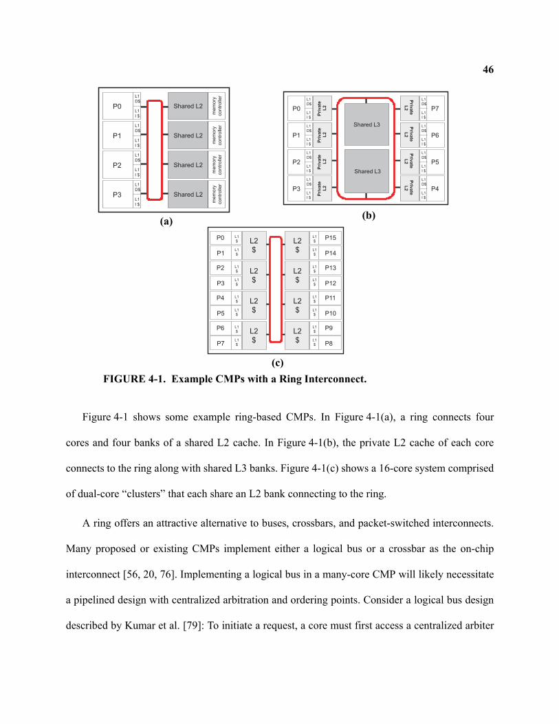
46
Figure 4-1 shows some example ring-based CMPs. In Figure 4-1(a), a ring connects four
cores and four banks of a shared L2 cache. In Figure 4-1(b), the private L2 cache of each core
connects to the ring along with shared L3 banks. Figure 4-1(c) shows a 16-core system comprised
of dual-core “clusters” that each share an L2 bank connecting to the ring.
A ring offers an attractive alternative to buses, crossbars, and packet-switched interconnects.
Many proposed or existing CMPs implement either a logical bus or a crossbar as the on-chip
interconnect [56, 20, 76]. Implementing a logical bus in a many-core CMP will likely necessitate
a pipelined design with centralized arbitration and ordering points. Consider a logical bus design
described by Kumar et al. [79]: To initiate a request, a core must first access a centralized arbiter
Shared L2
L1D$
L1I $
P0
L1D$
L1I $
P1
L1D$
L1I $
P2
L1D$
L1I $
P3
Shared L2
Shared L2
Shared L2
mem
ory
con
tro
ller
mem
ory
con
tro
ller
mem
ory
con
tro
ller
mem
ory
con
tro
ller
Shared L3
Shared L3
Pri
va
te
L2
L1D$
L1I $
P0
Pri
va
te
L2
L1D$
L1I $
P1
Pri
va
te
L2
L1D$
L1I $
P2
Pri
va
te
L2
L1D$
L1I $
P3
Priv
ate
L2
L1D$
L1I $
P7
Priv
ate
L2
L1D$
L1I $
P6
Priv
ate
L2
L1D$
L1I $
P5
Priv
ate
L2
L1D$
L1I $
P4
P0
P1L1$
L1$ L2
$
P2
P3L1$
L1$ L2
$
P4
P5L1$
L1$ L2
$
P6
P7L1$
L1$ L2
$
P15
P14L1$
L1$L2
$
P13
P12L1$
L1$L2
$
P11
P10L1$
L1$L2
$
P9
P8L1$
L1$L2
$
FIGURE 4-1. Example CMPs with a Ring Interconnect.
(a) (b)
(c)
47and then send its request to a queue. The queue creates the total order of requests, and resends the
request on a separate set of snoop links. Caches snoop the requests and send the results on another
set of links where the snoop results are collected at another queue. Finally the snoop queue
resends the final snoop results to all cores. This type of logical bus will result in significant perfor-
mance loss to recreate the ordering of an atomic bus. Crossbar interconnects, used in the Sun Nia-
gara [76] and Compaq Piranha [20], will also suffer scalability limits in terms of on-chip
resources because the number of wires grows with the square of endpoints. In fact the designers of
the IBM Cell interconnect chose a ring topology over a crossbar because of the efficiency of wires
[62].
Microarchitects can move to a packet-switched network using a general topology, like a grid
or torus, to create a scalable on-chip interconnect. However this “route packets, not wires”
approach [38] also comes with significant costs. First, implementing the interconnect itself
requires the correct design and verification of all queues, routers, and algorithms for routing with
deadlock avoidance. Second, significant state and area overhead may be devoted to buffers and
logic required for packet-switching. Third, a directory coherence protocol designed to operate
with an unordered network is usually needed for most topologies, requiring costly indirections
and acknowledgement messages. Fourth, proposed routers for CMPs require several pipeline
stages [80, 78], thus increasing the latency of communication and motivating additional research
on mechanisms, with their added complexity, to bypass router pipelines under certain conditions
[40, 78].
Rings offer many advantages including fast point-to-point links. The routers of a ring are very
simple and can be implemented with minimal (or no) buffering. Rings can also operate without
48back-pressure mechanisms. If the destination of a message lacks sufficient resources to handle it,
the message can remain traversing the ring until resources become available. In this way, a ring is
analogous to a “traffic roundabout”. In a traffic roundabout, once a car is able to enter the round-
about (ring), it continues to circulate until it is able to exit (acquire a buffer). A similar technique
uses a ring to implement the internal logic of a router in a general-purpose interconnect [1].
Rings offer simple, distributed arbitration and access methods [122]. The simplest method of
access is called a token ring (also known as a Newhall ring). In a token passing ring, only a single
node can transmit data at any time governed by a special token passed fairly around the ring. A
slotted ring allows multiple simultaneous transmitters, but the ring is segmented into fixed-sized
slots of different types (e.g., request and response slots). Nodes must wait until the header of an
available slot appears at the ring interface before transmission. In a register-insertion ring, nodes
can begin transmission immediately, but may be required to buffer incoming data during trans-
mission. To prevent loss of data during buffering, a node must cease transmission of data when
the buffer fills.
A ring can also aid in reliability. Reliability is projected to become a major obstacle in future
CMP designs [25] as both permanent and transient faults threaten to disrupt the progress of tech-
nology scaling. Aggarwal et al. [6] propose an architecture to facilitate configurable isolation
within a CMP by partitioning a single ring-based interconnect into multiple, isolated rings. A ring
architecture can also tolerate transient faults by using a source-based check of message integrity.
That is, the sender of a message can retain a copy while the message traverses the entire ring back
to the sender. If the message became corrupted along the way, the sender can then re-send the
message. As discussed in Section 4.5.1, this can have ramifications on the coherence protocol.
49Finally a ring may simplify the design of other related structures, such as cache banks, by con-
trolling the rate of message arrivals. For example, in a crossbar system, multiple cores can simul-
taneously issue requests to a cache bank. The cache bank would then have to arbitrate and select a
request to service from those waiting. On the other hand, cache banks attached to a ring service
requests from a single point of arrival with a maximum rate controlled by the speed of the ring.
In this chapter, we explore cache coherence techniques for ring architectures. Our approaches
apply to physical rings described in this section as well as logical rings on a general-purpose
packet-switched interconnect [124]. The primary issue we address is the ordering of coherence
requests on a ring. A topology of a ring suggests a natural round-robin ordering of requests. How-
ever existing snooping protocols rely on an atomic bus, and existing directory protocols suffer too
much overhead when operating on a ring. We first examine existing approaches that either recre-
ate a total order with an ordering point or use a greedy approach with unbounded retries. We then
offer a new approach to ring-based coherence that offers both fast performance by not relying on
ordering points, and stability by not using retries.
4.2 Ring-based Cache Coherence
The primary challenge toward implementing cache coherence on a ring is that the ordering
properties are not the same as a globally ordered bus. Figure illustrates how nodes on a ring may
see a different order of message arrivals depending on ring position. With a lack of total order, the
bus-based snooping protocol described in Section 2.2.1 would result in incorrect coherence.
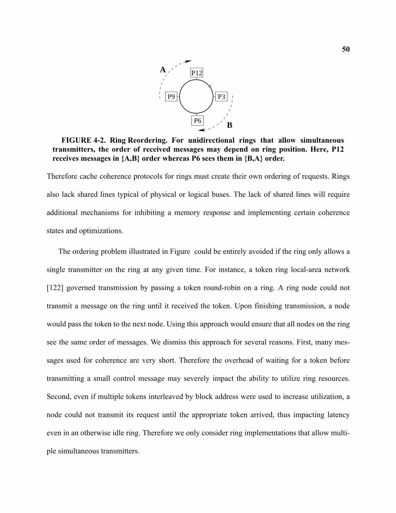
50
Therefore cache coherence protocols for rings must create their own ordering of requests. Rings
also lack shared lines typical of physical or logical buses. The lack of shared lines will require
additional mechanisms for inhibiting a memory response and implementing certain coherence
states and optimizations.
The ordering problem illustrated in Figure could be entirely avoided if the ring only allows a
single transmitter on the ring at any given time. For instance, a token ring local-area network
[122] governed transmission by passing a token round-robin on a ring. A ring node could not
transmit a message on the ring until it received the token. Upon finishing transmission, a node
would pass the token to the next node. Using this approach would ensure that all nodes on the ring
see the same order of messages. We dismiss this approach for several reasons. First, many mes-
sages used for coherence are very short. Therefore the overhead of waiting for a token before
transmitting a small control message may severely impact the ability to utilize ring resources.
Second, even if multiple tokens interleaved by block address were used to increase utilization, a
node could not transmit its request until the appropriate token arrived, thus impacting latency
even in an otherwise idle ring. Therefore we only consider ring implementations that allow multi-
ple simultaneous transmitters.
P3
P6
P12
P9
A
B
FIGURE 4-2. Ring Reordering. For unidirectional rings that allow simultaneoustransmitters, the order of received messages may depend on ring position. Here, P12receives messages in {A,B} order whereas P6 sees them in {B,A} order.
51In addition to allowing multiple simultaneous transmitters, deploying a ring in a modern CMP
requires additional aggressive implementation techniques. In particular, to minimize latency a
ring-based system should immediately forward request messages to the next node (i.e., eager for-
warding [124]) instead of first performing a snoop and then forwarding the message (i.e., lazy for-
warding).
One option for coherence on a ring-based interconnect is to employ a protocol that has no reli-
ance on the ordering properties of the underlying interconnect [91], such as a directory-based pro-
tocol. The Scalable Coherence Interconnect (SCI) [53] is an example of a system that used a
directory-based protocol on ring interconnects. Unfortunately directory-based coherence is espe-
cially inefficient on a unidirectional ring because the sometimes numerous control messages must
make multiple ring traversals. The SCI protocol required four traversals alone to add a reader to
its linked directory structure of sharers (although other non-linked directory structures may per-
form better). We do not consider directory-based schemes in this chapter because they do not take
advantage of ring properties. Furthermore, to deal with racing requests, directory protocols either
entail additional complexity and logic overhead or employ starvation-prone Nacking schemes.
In the rest of this section, we develop ordering strategies for snooping protocols that do not
require directory state. We first assume a unidirectional ring for all messages for the same block
address. Bidirectional rings for data transfer will be discussed in Section 4.3.4.
4.2.1 ORDERING-POINT
The first class of protocols recreates the global ordering of an atomic bus by establishing a
point on the ring where all requests are ordered. The disadvantage of this approach is that requests
are not active until they reach the ordering point, thus increasing both latency and bandwidth. As
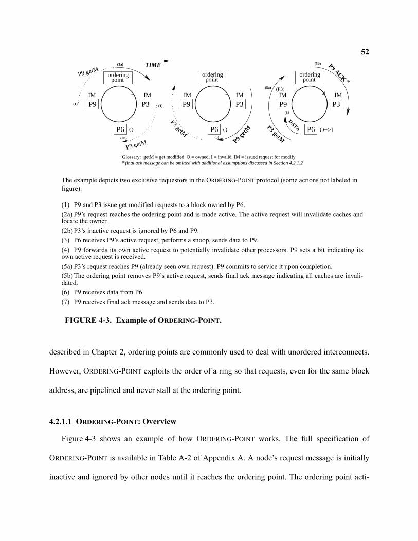
52
described in Chapter 2, ordering points are commonly used to deal with unordered interconnects.
However, ORDERING-POINT exploits the order of a ring so that requests, even for the same block
address, are pipelined and never stall at the ordering point.
4.2.1.1 ORDERING-POINT: Overview
Figure 4-3 shows an example of how ORDERING-POINT works. The full specification of
ORDERING-POINT is available in Table A-2 of Appendix A. A node’s request message is initially
inactive and ignored by other nodes until it reaches the ordering point. The ordering point acti-
P3
P6
P3
P6
P3
P6
orderingpoint
orderingpoint
orderingpoint
P9P9 P9IM
(P3)
(1) (1)
(2a)
(2b) (3)
(5a)
(5b)
*
TIME
P9 getM
IM IM
O
IM IM
O
P3 getM
P3 getMP9 g
etMP3 getM
O−>I
P9 ACK
IM
DATA
(6)
Glossary: getM = get modified, O = owned, I = invalid, IM = issued request for modifyfinal ack message can be omitted with additional assumptions discussed in Section 4.2.1.2*
FIGURE 4-3. Example of ORDERING-POINT.
The example depicts two exclusive requestors in the ORDERING-POINT protocol (some actions not labeled in figure):
(1) P9 and P3 issue get modified requests to a block owned by P6.(2a) P9’s request reaches the ordering point and is made active. The active request will invalidate caches andlocate the owner.(2b) P3’s inactive request is ignored by P6 and P9.(3) P6 receives P9’s active request, performs a snoop, sends data to P9.(4) P9 forwards its own active request to potentially invalidate other processors. P9 sets a bit indicating itsown active request is received.(5a) P3’s request reaches P9 (already seen own request). P9 commits to service it upon completion.(5b) The ordering point removes P9’s active request, sends final ack message indicating all caches are invali-dated. (6) P9 receives data from P6.(7) P9 receives final ack message and sends data to P3.
53vates the request by setting a bit in the header of the message. In this manner, the ordering point
creates a consistent order of active request messages seen by other processors. The owning node
will eventually complete a snoop and send data to the requesting core. After the active request
message traverses the entire ring, the ordering point removes the message from the ring and, for a
GETM request, sends a final acknowledgement message to the requestor indicating that all
snoops (invalidations) have completed.
To prevent the ordering point from blocking subsequent requests while a request is already in-
progress for the same block address, a requestor must record the first active request message
received after observing and forwarding its own active request. By doing so, it commits to satisfy
one subsequent request, thereby forming a linked chain of coherence service. If any of the subse-
quent requests are for exclusive access (GETM), the requestor will also invalidate itself upon
completing its own request and servicing the next. Therefore the Miss Status Holding Registers
(MSHR) [77] include a {requestor id} field and a {observed GETM} bit.
Replacements of owned or dirty data must be ordered with requests to ensure the linked chain
of coherence requests does not break down. A cache can, however, silently replace shared (non-
owned) data. Our replacement algorithm assumes the memory controller functions as the ordering
point for the appropriate interleaved cache lines. The replacing cache controller places a PUT
message on the ring which is ordered with other potential requests at the memory controller
(ordering point). The memory controller also allocates an entry in a MSHR-like table, and enters
state WP to indicate that a writeback operation is pending. When the cache controller receives its
own PUT request, it then sends data to the memory controller to complete the replacement. If,
however, the memory controller receives another GETM or GETS request while in state WP, it
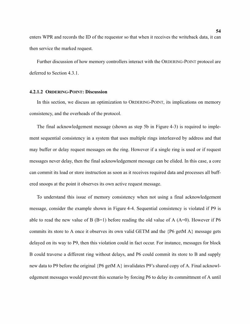
54enters WPR and records the ID of the requestor so that when it receives the writeback data, it can
then service the marked request.
Further discussion of how memory controllers interact with the ORDERING-POINT protocol are
deferred to Section 4.3.1.
4.2.1.2 ORDERING-POINT: Discussion
In this section, we discuss an optimization to ORDERING-POINT, its implications on memory
consistency, and the overheads of the protocol.
The final acknowledgement message (shown as step 5b in Figure 4-3) is required to imple-
ment sequential consistency in a system that uses multiple rings interleaved by address and that
may buffer or delay request messages on the ring. However if a single ring is used or if request
messages never delay, then the final acknowledgement message can be elided. In this case, a core
can commit its load or store instruction as soon as it receives required data and processes all buff-
ered snoops at the point it observes its own active request message.
To understand this issue of memory consistency when not using a final acknowledgement
message, consider the example shown in Figure 4-4. Sequential consistency is violated if P9 is
able to read the new value of B (B=1) before reading the old value of A (A=0). However if P6
commits its store to A once it observes its own valid GETM and the {P6 getM A} message gets
delayed on its way to P9, then this violation could in fact occur. For instance, messages for block
B could traverse a different ring without delays, and P6 could commit its store to B and supply
new data to P9 before the original {P6 getM A} invalidates P9’s shared copy of A. Final acknowl-
edgement messages would prevent this scenario by forcing P6 to delay its committment of A until
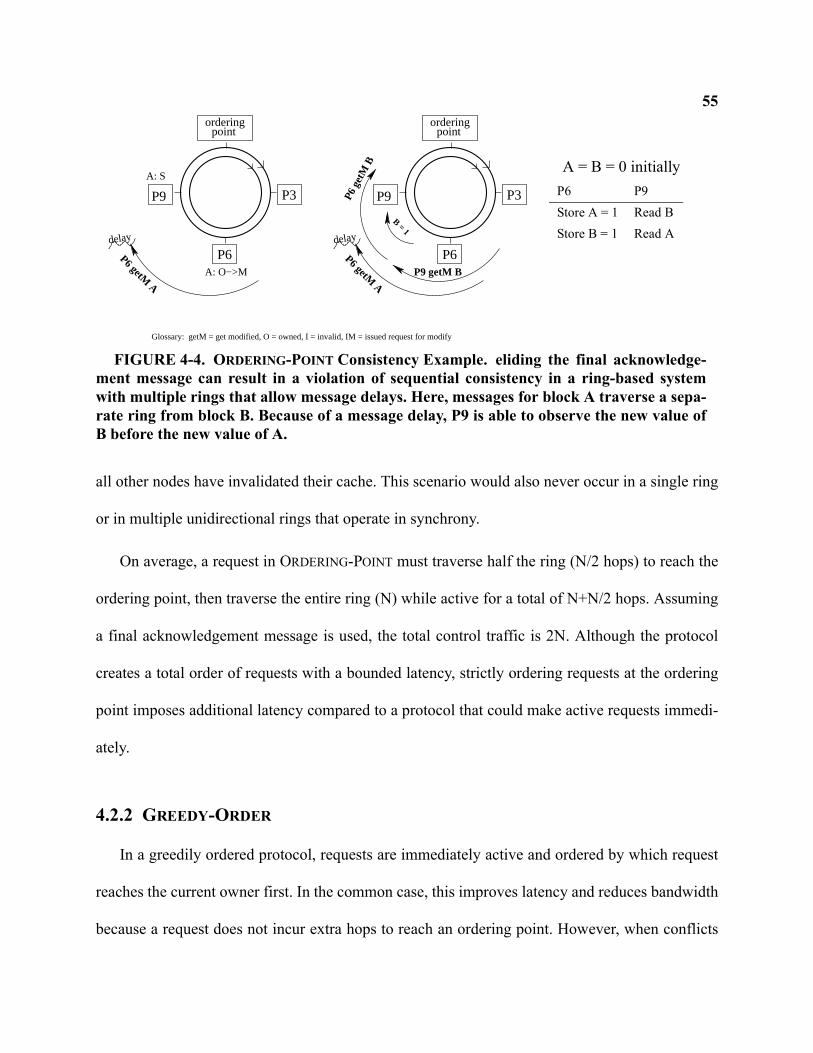
55
all other nodes have invalidated their cache. This scenario would also never occur in a single ring
or in multiple unidirectional rings that operate in synchrony.
On average, a request in ORDERING-POINT must traverse half the ring (N/2 hops) to reach the
ordering point, then traverse the entire ring (N) while active for a total of N+N/2 hops. Assuming
a final acknowledgement message is used, the total control traffic is 2N. Although the protocol
creates a total order of requests with a bounded latency, strictly ordering requests at the ordering
point imposes additional latency compared to a protocol that could make active requests immedi-
ately.
4.2.2 GREEDY-ORDER
In a greedily ordered protocol, requests are immediately active and ordered by which request
reaches the current owner first. In the common case, this improves latency and reduces bandwidth
because a request does not incur extra hops to reach an ordering point. However, when conflicts
P3
P6
orderingpoint
P9
P6 getM A
P9 getM B
delay
P6 g
etM
B
B = 1
P3
P6
orderingpoint
Glossary: getM = get modified, O = owned, I = invalid, IM = issued request for modify
P9
P6 getM A
delay
A: O−>M
A: S
FIGURE 4-4. ORDERING-POINT Consistency Example. eliding the final acknowledge-ment message can result in a violation of sequential consistency in a ring-based systemwith multiple rings that allow message delays. Here, messages for block A traverse a sepa-rate ring from block B. Because of a message delay, P9 is able to observe the new value ofB before the new value of A.
A = B = 0 initiallyP6 P9Store A = 1 Read BStore B = 1 Read A
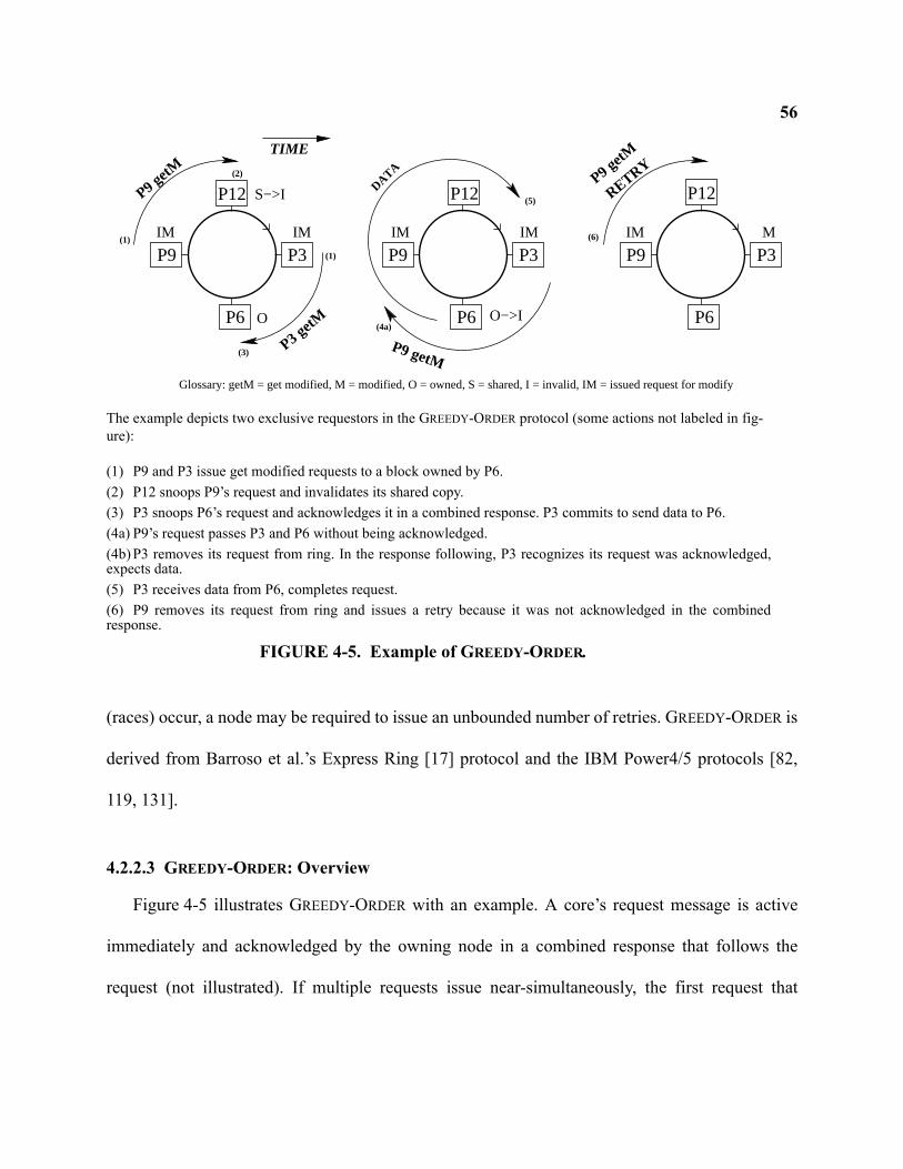
56
(races) occur, a node may be required to issue an unbounded number of retries. GREEDY-ORDER is
derived from Barroso et al.’s Express Ring [17] protocol and the IBM Power4/5 protocols [82,
119, 131].
4.2.2.3 GREEDY-ORDER: Overview
Figure 4-5 illustrates GREEDY-ORDER with an example. A core’s request message is active
immediately and acknowledged by the owning node in a combined response that follows the
request (not illustrated). If multiple requests issue near-simultaneously, the first request that
P3
P6
P3
P6
P3
P6
P12 P12P12
P9P9 P9IM IMIM
P3 getM
DATA
P9 getM
(1)
(1)
(5)
TIME
IM
O
S−>I
O−>I
Glossary: getM = get modified, M = modified, O = owned, S = shared, I = invalid, IM = issued request for modify
(2)
(3)
(4a)
(6)
P9 getM
RETRY
IM M
P9 getM
The example depicts two exclusive requestors in the GREEDY-ORDER protocol (some actions not labeled in fig-ure):
(1) P9 and P3 issue get modified requests to a block owned by P6.(2) P12 snoops P9’s request and invalidates its shared copy.(3) P3 snoops P6’s request and acknowledges it in a combined response. P3 commits to send data to P6.(4a) P9’s request passes P3 and P6 without being acknowledged.(4b) P3 removes its request from ring. In the response following, P3 recognizes its request was acknowledged,expects data.(5) P3 receives data from P6, completes request.(6) P9 removes its request from ring and issues a retry because it was not acknowledged in the combinedresponse.
FIGURE 4-5. Example of GREEDY-ORDER.
57reaches the owner is acknowledged and wins the race. Otherwise, the request is not acknowledged
and the losing requestor issues a retry after inspecting the combined response.
The example in Figure 4-5 shows a conflict situation with multiple exclusive requestors. If an
exclusive request reaches any node with a shared request outstanding, we adopt Barroso’s policy
[17] in which the shared requestor must abort the request and issue a retry, even though a data
response to the shared requestor may already be in flight. The shared request aborts because the
owner may respond to an exclusive request while data travels to a shared request resulting in a
coherence violation. Essentially this policy always prioritizes the writer when racing with a reader
even if the read request reaches the owner first. An alternate approach prevents this case of possi-
ble incoherence by transferring ownership on any read request so that racing writes would fail and
retry. However, we found this policy resulted in more pathological starvation because of the
increased likelihood of a shared request missing the in-flight owner. GREEDY-ORDER’s cache con-
troller is specified in Table A-3 of Appendix A, with shaded cells to indicate the state-transitions
resulting in a retry.
Replacement of owned or exclusive data requires no special action in GREEDY-ORDER. The
replacing cache controller simply sends the data to the memory controller. Requests racing with a
replacement operation will simply issue retries. Further discussion of how memory controllers
interact with the GREEDY-ORDER protocol is deferred to Section 4.3.1.
4.2.2.4 GREEDY-ORDER: Discussion
A system that uses retries to handle contention avoids starvation only if future system condi-
tions eventually allow a core’s retry to succeed in all cases. Probabilistic systems are acceptable in
other domains of computing, such as Ethernet [102]. But feedback from industry indicates chip
58designers prefer stronger, non-probabilistic guarantees of liveness for a coherence protocol. Fur-
thermore, a system like Ethernet exploits the carrier sense property to prove its liveness [118]
whereas we are not aware of a general proof, for a greedily ordered protocol, that shows the sys-
tem will always avoid a pathological retry scenario.
We considered other techniques to address retries in GREEDY-ORDER. Exponential backoff or
adding randomness to retries can increase the probability of success, but does not guarantee live-
ness. Attaching a priority (such as the age of the request) does not solve the problem because it
would require the core to either remember starving requests, or to wait until multiple requests are
received in order to prioritize the set of requestors. We also considered an approach that carefully
constructs a distributed linked chain of requests such that a node hands off the block to the next
requestor, like done in ORDERING-POINT. But correctly constructing this list without an ordering
point adds significant complexity and constraints, especially when considering the effects of bank
contention and interfacing with memory (discussed in Section 3).
Another disadvantage of GREEDY-ORDER is that it relies on a snoop response from every
cache for every request. Implementing this efficiently on a ring (i.e., without an entire trailing
response message) can use a combined response with synchrony such that response bits trail a
request message by a fixed number of cycles. This fixed timing increases the complexity and con-
straints of the system. For example, the architected fixed timing must account for bank contention
and the various snoop times of different-sized caches. If a request cannot be snooped within the
architected fixed time, it must be negatively acknowledged (Nacked) and subsequently retried by
the requestor. Increasing the delay in the fixed timing decreases the probability of a Nack, how-
59ever this will negatively impact many non-delayed requests. Making the timing too aggressive
will result in extra Nacks and retries, increasing the probability of pathological starvation.
We seek a better mechanism that bounds every node’s coherence operation for performance
stability, but does not use an ordering point. Furthermore, we seek a coherence protocol that does
not rely on a synchronous snoop response for message efficiency. We now present a new class of
ring protocols that orders completion of requests by the position on the ring.
4.2.3 RING-ORDER
Ideally, a request in a ring protocol is active immediately, does not require retries to handle
contention, and incurs minimal latency and bandwidth. We develop a new class of protocols that
achieve these goals by completing requests in ring order. In RING-ORDER, a request is immedi-
ately active and seeks to find the current owner. The response from the owner can subsequently
then be removed from the ring by other requestors on the path, thereby ordering requests by ring
position.
4.2.3.5 RING-ORDER: Overview
RING-ORDER uses a token-counting approach, inspired by token coherence [93], that passes
tokens to ring nodes in order to ensure coherence safety. Recall from Section 2.2.6 that counting
tokens can directly enforce the coherence invariant by allowing either one writer or multiple read-
ers at any point in time. That is, a set of T tokens can be associated with each memory block in the
system. To write a block, a core must possess all the tokens and to read a block, a core must pos-
sess a single token. Coherence requests in RING-ORDER cause tokens to flow unidirectionally on
the ring. Requestors needing tokens collect the tokens until the request is satisfied.
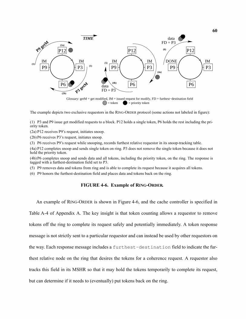
60
An example of RING-ORDER is shown in Figure 4-6, and the cache controller is specified in
Table A-4 of Appendix A. The key insight is that token counting allows a requestor to remove
tokens off the ring to complete its request safely and potentially immediately. A token response
message is not strictly sent to a particular requestor and can instead be used by other requestors on
the way. Each response message includes a furthest-destination field to indicate the fur-
thest relative node on the ring that desires the tokens for a coherence request. A requestor also
tracks this field in its MSHR so that it may hold the tokens temporarily to complete its request,
but can determine if it needs to (eventually) put tokens back on the ring.
P3
P6
P3
P6
P12P12
P3
P6
P12
P9 P9
P9 getM
P3 getM
dataFD = P3
DONE
P9
FD = P3data
IM IM IM IM IM(1)
(1) (5)
(6)
TIME
Glossary: getM = get modified, IM = issued request for modify, FD = furthest−destination field
(2a)
(2b)
(4b)
(4a)
= priority token= token
The example depicts two exclusive requestors in the RING-ORDER protocol (some actions not labeled in figure):
(1) P3 and P9 issue get modified requests to a block. P12 holds a single token, P6 holds the rest including the pri-ority token. (2a) P12 receives P9’s request, initiates snoop.(2b) P6 receives P3’s request, initiates snoop.(3) P6 receives P9’s request while snooping, records furthest relative requestor in its snoop-tracking table.(4a) P12 completes snoop and sends single token on ring. P3 does not remove the single token because it does nothold the priority token.(4b) P6 completes snoop and sends data and all tokens, including the priority token, on the ring. The response istagged with a furthest-destination field set to P3.(5) P9 removes data and tokens from ring and is able to complete its request because it acquires all tokens.(6) P9 honors the furthest-destination field and places data and tokens back on the ring.
FIGURE 4-6. Example of RING-ORDER.
61To ensure starvation avoidance, a policy must be in place to prevent multiple exclusive
requestors from holding a subset of the tokens. We distinguish one of the tokens as the priority
token. Similar to the owner token used by token coherence, the priority token denotes which
responder sends data. More importantly, it allows requests to complete in ring order by prioritiz-
ing the requestors as it moves around the ring. The priority token breaks the symmetry by distin-
guishing which requestor should hold tokens. A requesting node must remove the incoming
priority token from the ring and hold onto it until its request completes. Other non-priority tokens,
in flight due to a writeback or exclusive request, must coalesce with the priority token. Thus a
requestor does not acquire non-priority tokens until it holds the priority token. If an exclusive
requestor is holding the priority token, it updates the furthest-destination field in its MSHR when
it receives other requests while waiting for tokens. The furthest destination field also includes a
single bit to indicate if any requestor seeks all the tokens.
4.2.3.6 RING-ORDER: Cache Replacement and Token Coalescing
RING-ORDER coalesces tokens on the ring before replacing them to memory. In doing so,
memory can use a 1-bit token count per memory block. RING-ORDER’s coalescement process
works as follows: a cache either replacing all tokens or non-priority tokens take no special action
and simply place them on the ring. If a cache observes an incoming message containing non-pri-
ority tokens less than the maximum, then a snoop is initiated to determine if the cache bank holds
the priority token. If the bank holds the priority token, it accepts the tokens by adding them to the
token count in the cache tag. Otherwise the message forwards to the next node on the ring until
the bank holding the priority token is located. The memory controller accepts only replacement
messages that contain all the tokens.
62Replacing the priority token requires special action to prevent deadlock. Instead of immedi-
ately placing the priority token on the ring, the cache bank must instead place a PUT message on
the ring and enter the transient state COA. The PUT message locates another cache bank with
non-priority tokens. Upon locating this cache bank with non-priority tokens, the bank temporarily
pins the block by entering state P and sends a PUT-ACK to acknowledge the requestor of the
PUT. Once the PUT-ACK is received in state COA, the cache sends the priority token to complete
its replacement process. Finally while in state COA, if the cache snoops a request message, it also
completes the replacement process by responding to the request with the priority token, but it also
sends a PUT-CANCEL message to ensure no other cache bank remains pinned.
RING-ORDER also allows the clean replacement of data to reduce interconnect bandwidth.
Recall that the priority token normally carries the data in response to requests. A replacement
message carrying the priority token can omit the data if it is not dirty. However if a subsequent
requestor removes the replacement message containing a data-less priority token, then it must
send an explicit MEMORY-FETCH message to obtain the data from the memory controller. In
practice, this replacement-request race should rarely occur.
4.2.3.7 RING-ORDER: Discussion
RING-ORDER minimizes data transfer, because all requesting nodes complete their requests as
data moves around the ring once. One suspected negative aspect of our protocol is that a writer
may need to collect tokens from multiple sharers, with a message for each. We could further opti-
mize this by using a combined response that collects tokens. We choose not to because our obser-
vations corroborate other studies showing most invalidations are for few caches (most commonly
only one cache) [51, 92]. We do implement a simple optimization that allows a requestor to
63remove and hold non-priority tokens before receiving the in-flight priority token, but only if there
are no other concurrent requests. To detect other concurrent requests, a bit is set in the MSHR on
observing another request message, and the controller examines the furthest destination of each
incoming response message to determine if the response was sent on behalf of another concurrent
request.
RING-ORDER applies to rings with relaxed timing, or even asynchronous circuit designs [136]
because it avoids a synchronous combined snoop response. The same property will also be bene-
ficial when applied to hierarchical systems (e.g., a ring-of-rings) because a system-wide snoop
response is unnecessary.
4.2.3.8 RING-ORDER: Comparisons to Token Coherence
RING-ORDER was inspired by token coherence. Token coherence was originally developed for
glueless multiprocessor systems where tokens were passed to single-core nodes. While single-
core nodes typically contained several caches, it was assumed that coherence within a node was
handled by mechanisms other than the token coherence protocol because the hierarchy was pri-
vate. What actually comprises a node in RING-ORDER depends on the target system. In Figure 4-
1(a), each node consists of a core and its L1 caches. In Figure 4-1(b), the private L2 cache of each
core connects to the ring. In Figure 4-1(c), the dual-core clusters are considered ring nodes and
other mechanisms must be used to maintain coherence within a cluster.
Unlike token coherence, RING-ORDER does not use retries or persistent requests [95] to ensure
forward progress. Instead, we exploit ring order to guarantee that initial requests always succeed
and we use the priority token to break the symmetry of multiple requestors holding tokens. In
64addition, RING-ORDER memory stores only a single bit per memory block to track whether it con-
tains all or none of the tokens.
4.3 Implementation Issues
This section describes some implementation issues and details for deploying ORDERING-
POINT, GREEDY-ORDER, and RING-ORDER in actual CMPs.
4.3.1 Interface to DRAM
Ring-based CMPs must interact with off-chip DRAM via on-chip memory controllers1. In
prior bus-based snooping systems, the memory controller would always respond to a coherence
request unless inhibited by a shared intervention line asserted by a cache bank. Such shared lines
do not exist in a ring interconnect thus requiring other strategies to access the data from DRAM
when the data is not available on the ring.
One option collects a snoop response from every cache on every request to determine if a sep-
arate request should issue to memory. This scheme is used by the IBM Power4 and Power5 proto-
cols [82]. In these machines, the memory controller attaches to the ring and speculatively
prefetches a memory block when observing a request on the ring. On collecting the combined
snoop response, the requestor determines if it requires the data from memory, and then explicitly
sends a separate message on the ring to the memory controller to fetch the data (already
prefetched from DRAM by the memory controller). This scheme is possible on a CMP-based
ring, however it incurs costly bandwidth overhead and may hurt memory latency if the extra
1. Industry trends point towards memory controllers integrated on-chip. We use this assumption for the solutions in this disserta-
tion.
65memory request message is not overlapped with the DRAM access. Moreover, this approach
wastes precious off-chip bandwidth on unused lines prefetched from DRAM and increases power
usage. Instead, our strategy for ORDERING-POINT, GREEDY-ORDER, and RING-ORDER associates
one bit with every block in memory to allow the memory controller to participate like a processor
node.
For each block of data in memory, an extra bit is stored to determine if the memory controller
should source the data on a request. These owner bits [46] can either use a reserved portion of
DRAM to store all bits in a contiguous portion of the address space, employ ECC re-encoding
techniques [48], or use memory modules that implement the extra metabit. A set owner bit indi-
cates that memory should respond to a GETM or GETS request with data. A GETM request will
always clear the owner bit because the requestor now owns the block. To support clean cache-to-
cache transfers, a GETS request should also clear the owner bit such that the on-chip requestor
owns the block and responds to future on-chip GETS requests.
For RING-ORDER, the owner bit represents whether or not memory contains all of the tokens,
or none of the tokens. Thus unlike token coherence as previously published, we reduce the token
count at memory down to a single-bit per block. We do so by adding an invariant that memory
only sources and sinks messages containing all of the tokens for a given block. To enforce this
invariant, RING-ORDER coalesces tokens during cache replacement as described in
Section 4.2.3.6.
The owner bits allow a memory controller to participate in the coherence protocol by respond-
ing to GETS and GETM requests with data. Accessing these bits also requires a costly off-chip
DRAM access. Furthermore, for a protocol that may use a synchronous snoop response, like
66GREEDY-ORDER, accessing the owner bit in off-chip DRAM cannot occur within a reasonable
architected snoop time.
To reduce unnecessary DRAM accesses, we therefore cache the owner bits in a memory inter-
face cache (MIC) located at each on-chip memory controller. This will eliminate the off-chip
access, thereby saving pin bandwidth, on most requests that can obtain the data from an on-chip
source. However associating a single owner-bit with an entire tag leads to an inefficient structure.
We therefore use a coarse-grained structure to associate N bits with each tag. If the owner bits in
DRAM are arranged in a way amenable to fetching M at a time (such as using a reserved portion
of address space) and M == N, then every miss in the MIC fetches all M bits. If M != N, then each
tag in the MIC must also contain N/M sector bits indicating the validity of each M-bit sector. We
expect spatial locality will make this approach effective.
A miss to the MIC in ORDERING-POINT and RING-ORDER only results in an off-chip DRAM
access to fetch the owner-bit for the block in question. The controller could optionally fetch the
data block in parallel with the owner bit in case the bit is set. If a request in GREEDY-ORDER
misses in the MIC, then the memory controller must Nack the request if the protocol uses a syn-
chronous snoop response.
An alternative implementation of a memory interface cache summarizes all on-chip caches
with a duplicate tag structure. We did not evaluate this approach because our coarse-grained MIC
performs quite well (Section 4.4.2), and avoids the very wide aggregate associativity and signifi-
cant area overhead of duplicate tags.
674.3.2 Exclusive State
Alternative ordering strategies present challenges for implementing the exclusive cache state
(E-state). GREEDY-ORDER achieves the E-state with an added bit to the combined response that
indicates if any sharer exists (logically similar to a shared intervention signal). RING-ORDER has
the equivalent of an exclusive state because any response from memory logically contains all the
tokens, and clean data is omitted from token replacement messages. In ORDERING-POINT, how-
ever, an exclusive state is difficult because a requestor does not receive a combined snoop
response from every cache and because memory cannot determine if other sharers exist even if its
owner bit is set. One solution might associate an additional exclusive bit with each memory block
(and MIC). But the memory controller cannot determine when to reset the exclusive bit without
tracking a count of sharers. Hence our ORDERING-POINT protocol lacks an E-state.
4.3.3 Ring Interface
In this section, we consider any protocol-dependent capabilities required of the ring protocols
at the ring interface.
For all protocols, the ring interface must deliver coherence requests to the cache controller
while eagerly forwarding the message to the next node. For ORDERING-POINT and GREEDY-
ORDER, the ring interface must also remove response messages destined for the node as well as
request messages originating from the node. Response messages in RING-ORDER are treated
slightly differently because the ring interface must have knowledge of outstanding requests in
order to determine if a token-carrying message should be removed. Such functionality should
have minimal impact on the ring interface design and performance.
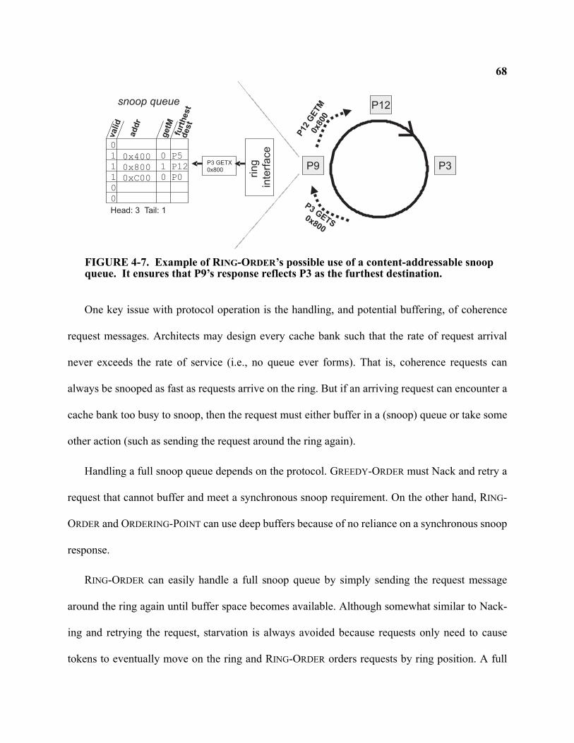
68
One key issue with protocol operation is the handling, and potential buffering, of coherence
request messages. Architects may design every cache bank such that the rate of request arrival
never exceeds the rate of service (i.e., no queue ever forms). That is, coherence requests can
always be snooped as fast as requests arrive on the ring. But if an arriving request can encounter a
cache bank too busy to snoop, then the request must either buffer in a (snoop) queue or take some
other action (such as sending the request around the ring again).
Handling a full snoop queue depends on the protocol. GREEDY-ORDER must Nack and retry a
request that cannot buffer and meet a synchronous snoop requirement. On the other hand, RING-
ORDER and ORDERING-POINT can use deep buffers because of no reliance on a synchronous snoop
response.
RING-ORDER can easily handle a full snoop queue by simply sending the request message
around the ring again until buffer space becomes available. Although somewhat similar to Nack-
ing and retrying the request, starvation is always avoided because requests only need to cause
tokens to eventually move on the ring and RING-ORDER orders requests by ring position. A full
0x800
0x400
0xC00 P0
P12
P51
1
1
0
0
0
valid
ad
dr
furt
hest
dest
snoop queue
ring
inte
rface
P9
Head: 3 Tail: 1
P12
P3
P3GETS
0x800
getM
1
0
0
P12
GETM
0x80
0
P3 GETX0x800
FIGURE 4-7. Example of RING-ORDER’s possible use of a content-addressable snoop queue. It ensures that P9’s response reflects P3 as the furthest destination.
69buffer with ORDERING-POINT, however, is especially problematic because of the reliance on a
linked chain of requests. We not aware of an obvious solution for a request that encounters a full
snoop queue with ORDERING-POINT.
RING-ORDER may also require a content-addressable snoop queue to check for the existence
of a queued request for the same block address as the current incoming request. The protocol
makes a key assumption that a request message cannot bypass the priority token on the ring, and
eager request forwarding in the presence of buffered requests could violate this assumption with-
out additional logic. For example, consider a scenario illustrated in Figure 4-7 where P9 holds the
priority token and then queues two requests, a first request by P12 and then another request by P3.
Recall that both requests eagerly forward on the ring to the next node. When the cache bank pro-
cesses P12’s request, it sends the priority token on the ring with the furthest-destination set to P12.
However P3’s request was eagerly forwarded while buffered behind P12’s request. For correct
operation, the furthest-destination field should have been set to P3. Thus if requests ever queue,
correct operation requires that requests for the same block address combine to reflect the furthest
destination of both requests. To combine the requests, the snoop queue may require content-
addressable access to search for other queued requests. Such a CAM snoop queue may increase
overhead and power, but optimizations can greatly reduce the frequency of a CAM access. For
example, a simple Bloom filter [24] (or even a single bit denoting if any request is queued) can
quickly determine if the snoop queue must be searched for a given request.
4.3.4 Bidirectional Rings
CMP designers may choose to implement bidirectional rings by combining multiple unidirec-
tional rings in opposing directions. An obvious benefit of this approach is a reduction in the aver-
70age number of hops, from N/2 to N/4, required to transfer a message between nodes. This
approach is used by the IBM Cell [71] to reduce the latency of data transfer.
ORDERING-POINT, GREEDY-ORDER, and RING-ORDER as described thus far assume unidirec-
tional rings. Nonetheless, all three protocols can send data responses on any path as long as con-
trol messages travel unidirectionally. Sending data on the shortest path can reduce ring bandwidth
and power consumption. It can also improve performance by allowing the core to continue specu-
lative execution using the values obtained in the data response received early [59]. ORDERING-
POINT and GREEDY-ORDER require no protocol changes to utilize a bidirectional ring for data
transfer, because a data message is always sent to a specific destination.
RING-ORDER requires some protocol additions to allow for data responses to traverse a differ-
ent path. Recall that the original RING-ORDER protocol requires data to travel with the priority
token. We still require all tokens to traverse unidirectionally on the ring, but we can extend RING-
ORDER to send data on a different path while the tokens traverse unidirectionally. We do so by
replacing the data field that accompanies the priority token with a pointer to where data is sent via
a different message. In the common case, the requestor signals completion of the request when it
both receives that data message and all the tokens. In the event of a race where a different
requestor removes the priority token carrying a pointer to data sent elsewhere, it must send a new
message to fetch the data from the node denoted in the pointer.
Although coherence races are an important design point in any protocol, they are rare in prac-
tice. Thus we expect this approach for utilizing a bidirectional ring in a RING-ORDER protocol to
maintain performance expectations. Moreover, additional steps can be taken to ensure perfor-
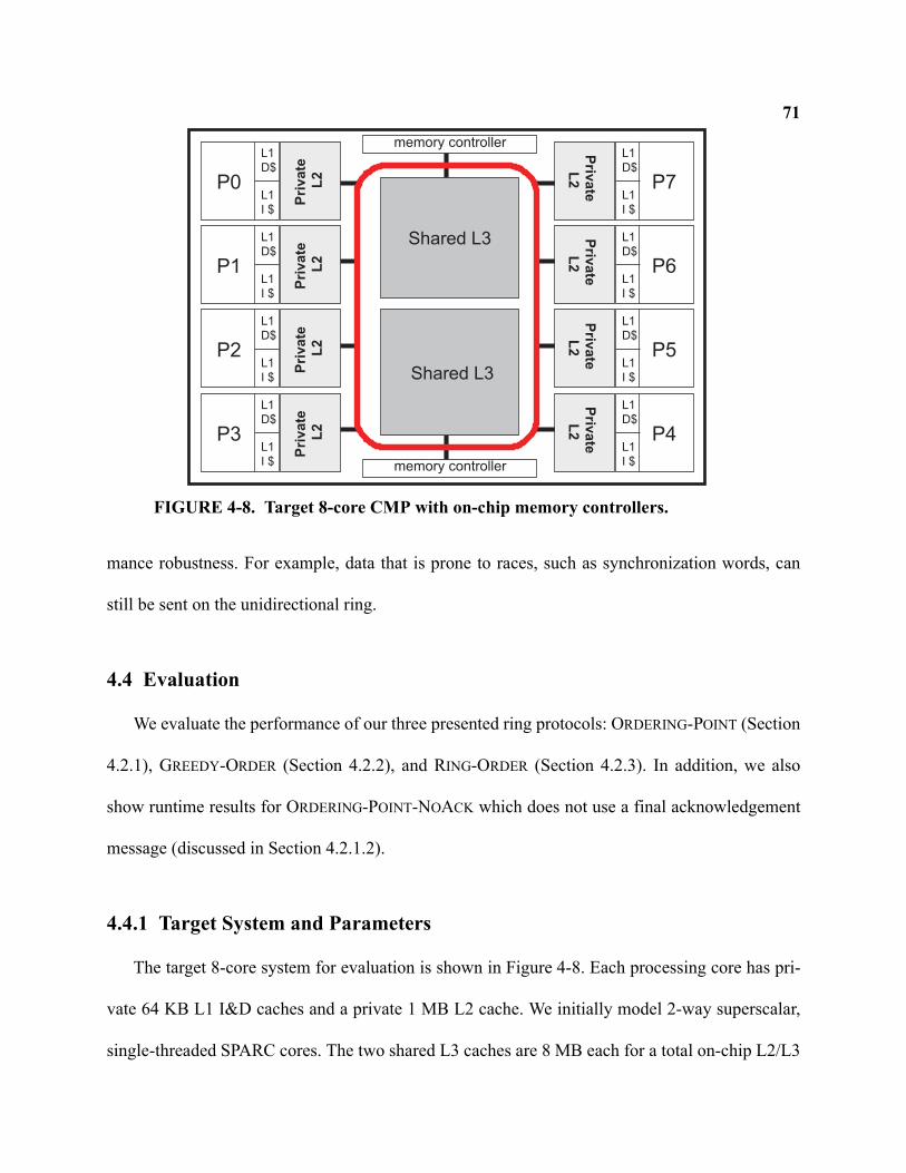
71
mance robustness. For example, data that is prone to races, such as synchronization words, can
still be sent on the unidirectional ring.
4.4 Evaluation
We evaluate the performance of our three presented ring protocols: ORDERING-POINT (Section
4.2.1), GREEDY-ORDER (Section 4.2.2), and RING-ORDER (Section 4.2.3). In addition, we also
show runtime results for ORDERING-POINT-NOACK which does not use a final acknowledgement
message (discussed in Section 4.2.1.2).
4.4.1 Target System and Parameters
The target 8-core system for evaluation is shown in Figure 4-8. Each processing core has pri-
vate 64 KB L1 I&D caches and a private 1 MB L2 cache. We initially model 2-way superscalar,
single-threaded SPARC cores. The two shared L3 caches are 8 MB each for a total on-chip L2/L3
memory controller
Shared L3
Shared L3
Pri
va
te
L2
L1D$
L1I $
P0
memory controller
Pri
va
te
L2
L1D$
L1I $
P1
Pri
va
te
L2
L1D$
L1I $
P2
Pri
va
te
L2
L1D$
L1I $
P3
Priv
ate
L2
L1D$
L1I $
P7
Priv
ate
L2
L1D$
L1I $
P6
Priv
ate
L2
L1D$
L1I $
P5
Priv
ate
L2
L1D$
L1I $
P4
FIGURE 4-8. Target 8-core CMP with on-chip memory controllers.
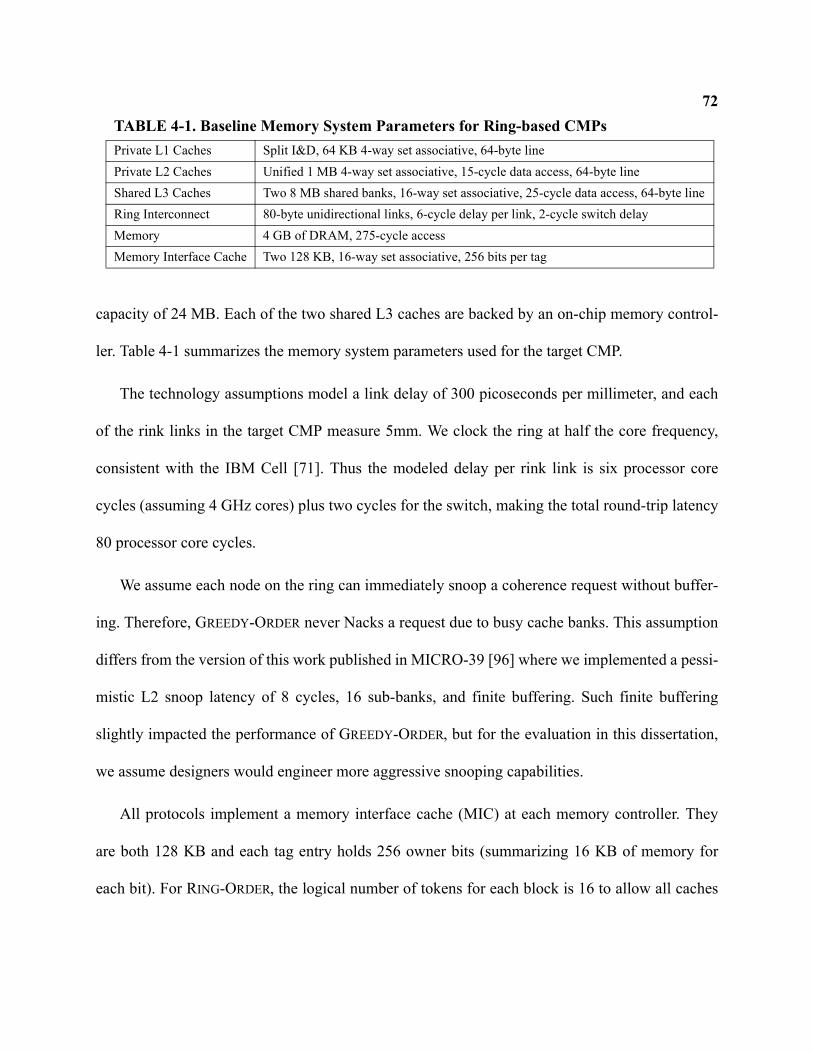
72
capacity of 24 MB. Each of the two shared L3 caches are backed by an on-chip memory control-
ler. Table 4-1 summarizes the memory system parameters used for the target CMP.
The technology assumptions model a link delay of 300 picoseconds per millimeter, and each
of the rink links in the target CMP measure 5mm. We clock the ring at half the core frequency,
consistent with the IBM Cell [71]. Thus the modeled delay per rink link is six processor core
cycles (assuming 4 GHz cores) plus two cycles for the switch, making the total round-trip latency
80 processor core cycles.
We assume each node on the ring can immediately snoop a coherence request without buffer-
ing. Therefore, GREEDY-ORDER never Nacks a request due to busy cache banks. This assumption
differs from the version of this work published in MICRO-39 [96] where we implemented a pessi-
mistic L2 snoop latency of 8 cycles, 16 sub-banks, and finite buffering. Such finite buffering
slightly impacted the performance of GREEDY-ORDER, but for the evaluation in this dissertation,
we assume designers would engineer more aggressive snooping capabilities.
All protocols implement a memory interface cache (MIC) at each memory controller. They
are both 128 KB and each tag entry holds 256 owner bits (summarizing 16 KB of memory for
each bit). For RING-ORDER, the logical number of tokens for each block is 16 to allow all caches
TABLE 4-1. Baseline Memory System Parameters for Ring-based CMPsPrivate L1 Caches Split I&D, 64 KB 4-way set associative, 64-byte linePrivate L2 Caches Unified 1 MB 4-way set associative, 15-cycle data access, 64-byte lineShared L3 Caches Two 8 MB shared banks, 16-way set associative, 25-cycle data access, 64-byte lineRing Interconnect 80-byte unidirectional links, 6-cycle delay per link, 2-cycle switch delayMemory 4 GB of DRAM, 275-cycle accessMemory Interface Cache Two 128 KB, 16-way set associative, 256 bits per tag

73
to hold a shared copy of data. Thus response messages and cache tags encode the token count with
4 bits, plus an additional bit to denote the priority token.
4.4.2 Performance
Figure 4-9 shows the normalized runtime for all four protocols in the baseline CMP with in-
order cores. Table A-1 in Appendix A shows the raw cycle and instruction counts. Runtime is nor-
malized to ORDERING-POINT. To first order, we observe that GREEDY-ORDER and RING-ORDER
outperform the ORDERING-POINT and ORDERING-POINT-NOACK protocols. RING-ORDER is 7-
86% faster than ORDERING-POINT and 5-47% faster than ORDERING-POINT-NOACK. The omis-
sion of ORDERING-POINT’s final acknowledgement message clearly reduces the runtime of this
protocol, however there is still significant overhead from activating messages at the ordering
point. RING-ORDER also manages to outperform GREEDY-ORDER by 10% for Apache. Although
0.0
0.5
1.0
norm
aliz
ed r
untim
e
Ord
erin
g-P
oint
Ord
erin
g-P
oint
-NoA
ck
Gre
edy-
Ord
er
Rin
g-O
rder
Apache
Ord
erin
g-P
oint
Ord
erin
g-P
oint
-NoA
ck
Gre
edy-
Ord
er
Rin
g-O
rder
OLTP
Ord
erin
g-P
oint
Ord
erin
g-P
oint
-NoA
ck
Gre
edy-
Ord
er
Rin
g-O
rder
SpecJBB
Ord
erin
g-P
oint
Ord
erin
g-P
oint
-NoA
ck
Gre
edy-
Ord
er
Rin
g-O
rder
Zeus
FIGURE 4-9. Normalized runtime, in-order cores.
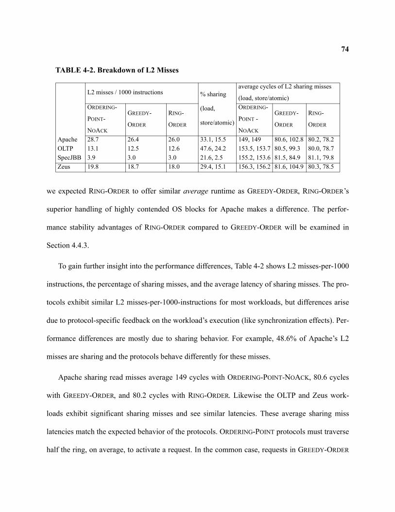
74
we expected RING-ORDER to offer similar average runtime as GREEDY-ORDER, RING-ORDER’s
superior handling of highly contended OS blocks for Apache makes a difference. The perfor-
mance stability advantages of RING-ORDER compared to GREEDY-ORDER will be examined in
Section 4.4.3.
To gain further insight into the performance differences, Table 4-2 shows L2 misses-per-1000
instructions, the percentage of sharing misses, and the average latency of sharing misses. The pro-
tocols exhibit similar L2 misses-per-1000-instructions for most workloads, but differences arise
due to protocol-specific feedback on the workload’s execution (like synchronization effects). Per-
formance differences are mostly due to sharing behavior. For example, 48.6% of Apache’s L2
misses are sharing and the protocols behave differently for these misses.
Apache sharing read misses average 149 cycles with ORDERING-POINT-NOACK, 80.6 cycles
with GREEDY-ORDER, and 80.2 cycles with RING-ORDER. Likewise the OLTP and Zeus work-
loads exhibit significant sharing misses and see similar latencies. These average sharing miss
latencies match the expected behavior of the protocols. ORDERING-POINT protocols must traverse
half the ring, on average, to activate a request. In the common case, requests in GREEDY-ORDER
TABLE 4-2. Breakdown of L2 Misses
L2 misses / 1000 instructions % sharing
(load,
store/atomic)
average cycles of L2 sharing misses
(load, store/atomic)ORDERING-
POINT-
NOACK
GREEDY-
ORDER
RING-
ORDER
ORDERING-
POINT -
NOACK
GREEDY-
ORDER
RING-
ORDER
Apache 28.7 26.4 26.0 33.1, 15.5 149, 149 80.6, 102.8 80.2, 78.2OLTP 13.1 12.5 12.6 47.6, 24.2 153.5, 153.7 80.5, 99.3 80.0, 78.7SpecJBB 3.9 3.0 3.0 21.6, 2.5 155.2, 153.6 81.5, 84.9 81.1, 79.8Zeus 19.8 18.7 18.0 29.4, 15.1 156.3, 156.2 81.6, 104.9 80.3, 78.5
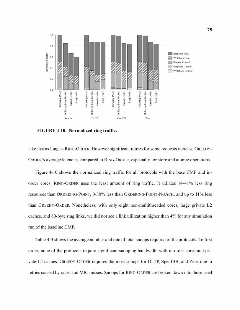
75
take just as long as RING-ORDER. However significant retries for some requests increase GREEDY-
ORDER’s average latencies compared to RING-ORDER, especially for store and atomic operations.
Figure 4-10 shows the normalized ring traffic for all protocols with the base CMP and in-
order cores. RING-ORDER uses the least amount of ring traffic. It utilizes 14-41% less ring
resources than ORDERING-POINT, 0-30% less than ORDERING-POINT-NOACK, and up to 11% less
than GREEDY-ORDER. Nonetheless, with only eight non-multithreaded cores, large private L2
caches, and 80-byte ring links, we did not see a link utilization higher than 4% for any simulation
run of the baseline CMP.
Table 4-3 shows the average number and rate of total snoops required of the protocols. To first
order, none of the protocols require significant snooping bandwidth with in-order cores and pri-
vate L2 caches. GREEDY-ORDER requires the most snoops for OLTP, SpecJBB, and Zeus due to
retries caused by races and MIC misses. Snoops for RING-ORDER are broken down into those used
0.0
0.2
0.4
0.6
0.8
1.0
norm
aliz
ed tr
affic Response Data
Writeback Data
Request Control
Response Control
Writeback Control
Ord
erin
g-P
oint
Ord
erin
g-P
oint
-NoA
ck
Gre
edy-
Ord
er
Rin
g-O
rder
Apache
Ord
erin
g-P
oint
Ord
erin
g-P
oint
-NoA
ck
Gre
edy-
Ord
er
Rin
g-O
rder
OLTP
Ord
erin
g-P
oint
Ord
erin
g-P
oint
-NoA
ck
Gre
edy-
Ord
er
Rin
g-O
rder
SpecJBB
Ord
erin
g-P
oint
Ord
erin
g-P
oint
-NoA
ck
Gre
edy-
Ord
er
Rin
g-O
rder
Zeus
FIGURE 4-10. Normalized ring traffic.
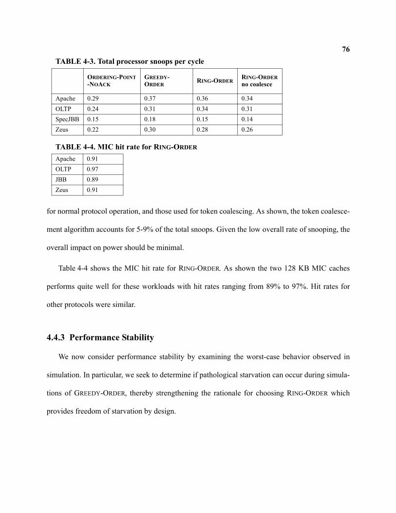
76
for normal protocol operation, and those used for token coalescing. As shown, the token coalesce-
ment algorithm accounts for 5-9% of the total snoops. Given the low overall rate of snooping, the
overall impact on power should be minimal.
Table 4-4 shows the MIC hit rate for RING-ORDER. As shown the two 128 KB MIC caches
performs quite well for these workloads with hit rates ranging from 89% to 97%. Hit rates for
other protocols were similar.
4.4.3 Performance Stability
We now consider performance stability by examining the worst-case behavior observed in
simulation. In particular, we seek to determine if pathological starvation can occur during simula-
tions of GREEDY-ORDER, thereby strengthening the rationale for choosing RING-ORDER which
provides freedom of starvation by design.
TABLE 4-3. Total processor snoops per cycle
ORDERING-POINT-NOACK
GREEDY-ORDER
RING-ORDERRING-ORDERno coalesce
Apache 0.29 0.37 0.36 0.34OLTP 0.24 0.31 0.34 0.31SpecJBB 0.15 0.18 0.15 0.14Zeus 0.22 0.30 0.28 0.26
TABLE 4-4. MIC hit rate for RING-ORDER
Apache 0.91OLTP 0.97JBB 0.89Zeus 0.91
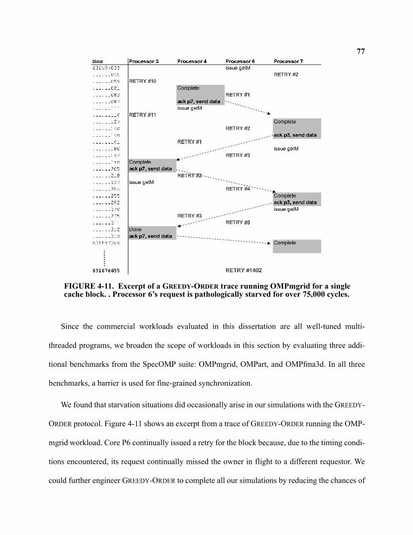
77
Since the commercial workloads evaluated in this dissertation are all well-tuned multi-
threaded programs, we broaden the scope of workloads in this section by evaluating three addi-
tional benchmarks from the SpecOMP suite: OMPmgrid, OMPart, and OMPfma3d. In all three
benchmarks, a barrier is used for fine-grained synchronization.
We found that starvation situations did occasionally arise in our simulations with the GREEDY-
ORDER protocol. Figure 4-11 shows an excerpt from a trace of GREEDY-ORDER running the OMP-
mgrid workload. Core P6 continually issued a retry for the block because, due to the timing condi-
tions encountered, its request continually missed the owner in flight to a different requestor. We
could further engineer GREEDY-ORDER to complete all our simulations by reducing the chances of
FIGURE 4-11. Excerpt of a GREEDY-ORDER trace running OMPmgrid for a single cache block. . Processor 6’s request is pathologically starved for over 75,000 cycles.
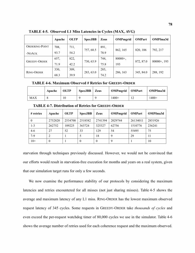
78
starvation through techniques previously discussed. However, we would not be convinced that
our efforts would result in starvation-free execution for months and years on a real system, given
that our simulation target runs for only a few seconds.
We now examine the performance stability of our protocols by considering the maximum
latencies and retries encountered for all misses (not just sharing misses). Table 4-5 shows the
average and maximum latency of any L1 miss. RING-ORDER has the lowest maximum observed
request latency of 345 cycles. Some requests in GREEDY-ORDER take thousands of cycles and
even exceed the per-request watchdog timer of 80,000 cycles we use in the simulator. Table 4-6
shows the average number of retries used for each coherence request and the maximum observed.
TABLE 4-5. Observed L1 Miss Latencies in Cycles (MAX, AVG)
Apache OLTP SpecJBB Zeus OMPmgrid OMPart OMPfma3d
ORDERING-POINT
-NOACK
708,
93.7
711,
54.2757, 68.5
891,
78.9862, 165 820, 106 792, 217
GREEDY-ORDER657,
71.9
822,
42.2730, 63.9
744,
75.8
80000+,
193872, 87.0 80000+, 193
RING-ORDER330,
68.3
309,
39.9283, 63.0
285,
74.2286, 163 345, 84.0 288, 192
TABLE 4-6. Maximum Observed # Retries for GREEDY-ORDER
Apache OLTP SpecJBB Zeus OMPmgrid OMPart OMPfma3d
MAX 8 10 9 9 1400+ 12 1400+
TABLE 4-7. Distribution of Retries for GREEDY-ORDER
# retries Apache OLTP SpecJBB Zeus OMPmgrid OMPart OMPfma3d
0 2752820 2534700 2518582 2741394 2029744 26134011 28519261-3 262752 109225 363724 325327 62756 1510776 2362414-6 27 52 33 129 54 55495 757-9 2 1 5 18 9 29 1110+ 0 1 0 0 9 1 10
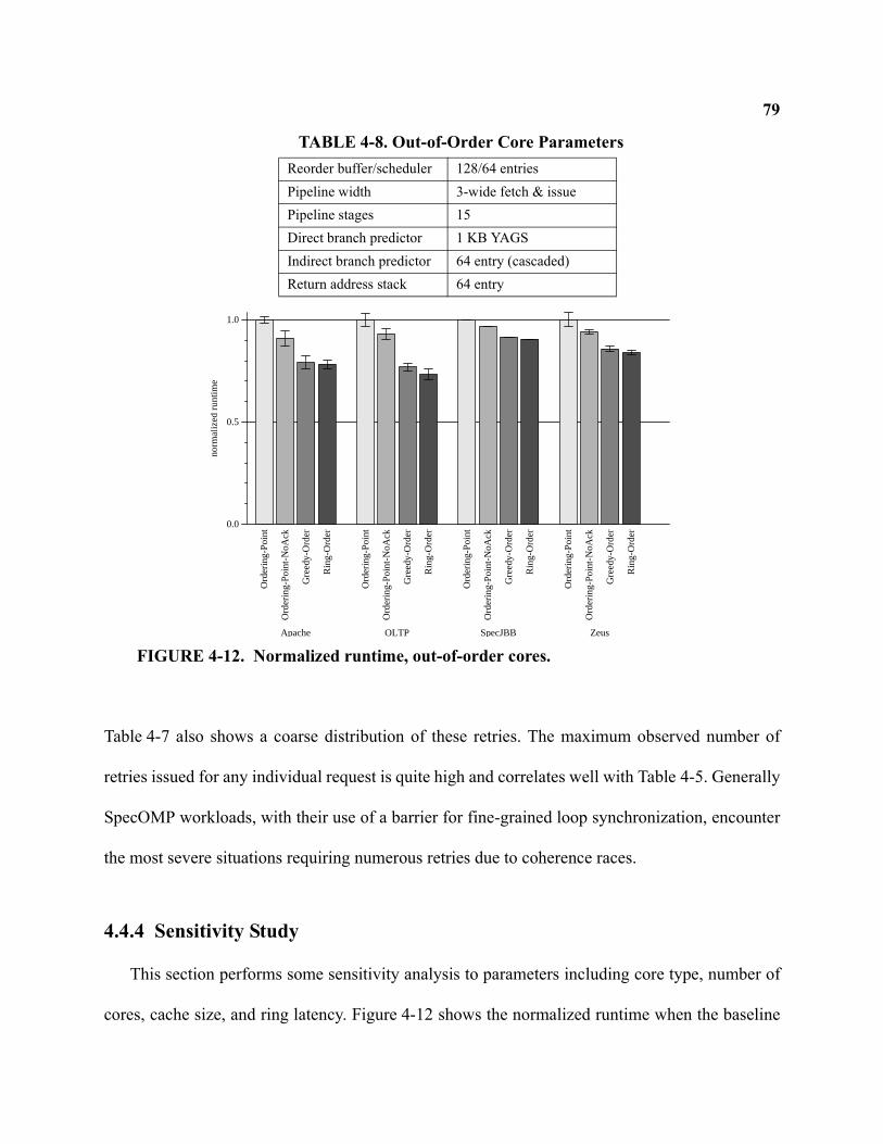
79
Table 4-7 also shows a coarse distribution of these retries. The maximum observed number of
retries issued for any individual request is quite high and correlates well with Table 4-5. Generally
SpecOMP workloads, with their use of a barrier for fine-grained loop synchronization, encounter
the most severe situations requiring numerous retries due to coherence races.
4.4.4 Sensitivity Study
This section performs some sensitivity analysis to parameters including core type, number of
cores, cache size, and ring latency. Figure 4-12 shows the normalized runtime when the baseline
TABLE 4-8. Out-of-Order Core ParametersReorder buffer/scheduler 128/64 entriesPipeline width 3-wide fetch & issuePipeline stages 15Direct branch predictor 1 KB YAGSIndirect branch predictor 64 entry (cascaded)Return address stack 64 entry
0.0
0.5
1.0
norm
aliz
ed r
untim
e
Ord
erin
g-P
oint
Ord
erin
g-P
oint
-NoA
ck
Gre
edy-
Ord
er
Rin
g-O
rder
Apache
Ord
erin
g-P
oint
Ord
erin
g-P
oint
-NoA
ck
Gre
edy-
Ord
er
Rin
g-O
rder
OLTP
Ord
erin
g-P
oint
Ord
erin
g-P
oint
-NoA
ck
Gre
edy-
Ord
er
Rin
g-O
rder
SpecJBB
Ord
erin
g-P
oint
Ord
erin
g-P
oint
-NoA
ck
Gre
edy-
Ord
er
Rin
g-O
rder
Zeus
FIGURE 4-12. Normalized runtime, out-of-order cores.
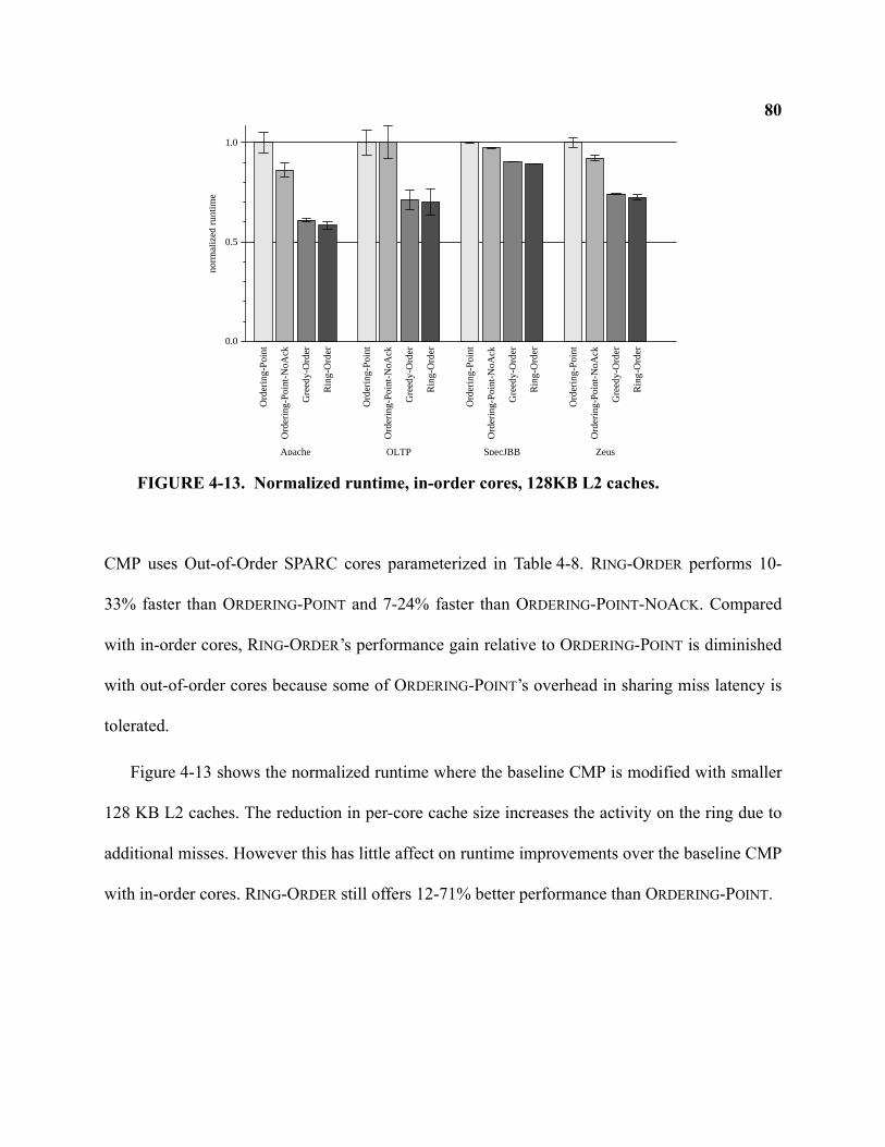
80
CMP uses Out-of-Order SPARC cores parameterized in Table 4-8. RING-ORDER performs 10-
33% faster than ORDERING-POINT and 7-24% faster than ORDERING-POINT-NOACK. Compared
with in-order cores, RING-ORDER’s performance gain relative to ORDERING-POINT is diminished
with out-of-order cores because some of ORDERING-POINT’s overhead in sharing miss latency is
tolerated.
Figure 4-13 shows the normalized runtime where the baseline CMP is modified with smaller
128 KB L2 caches. The reduction in per-core cache size increases the activity on the ring due to
additional misses. However this has little affect on runtime improvements over the baseline CMP
with in-order cores. RING-ORDER still offers 12-71% better performance than ORDERING-POINT.
0.0
0.5
1.0
norm
aliz
ed r
untim
e
Ord
erin
g-P
oint
Ord
erin
g-P
oint
-NoA
ck
Gre
edy-
Ord
er
Rin
g-O
rder
Apache
Ord
erin
g-P
oint
Ord
erin
g-P
oint
-NoA
ck
Gre
edy-
Ord
er
Rin
g-O
rder
OLTP
Ord
erin
g-P
oint
Ord
erin
g-P
oint
-NoA
ck
Gre
edy-
Ord
er
Rin
g-O
rder
SpecJBB
Ord
erin
g-P
oint
Ord
erin
g-P
oint
-NoA
ck
Gre
edy-
Ord
er
Rin
g-O
rder
Zeus
FIGURE 4-13. Normalized runtime, in-order cores, 128KB L2 caches.
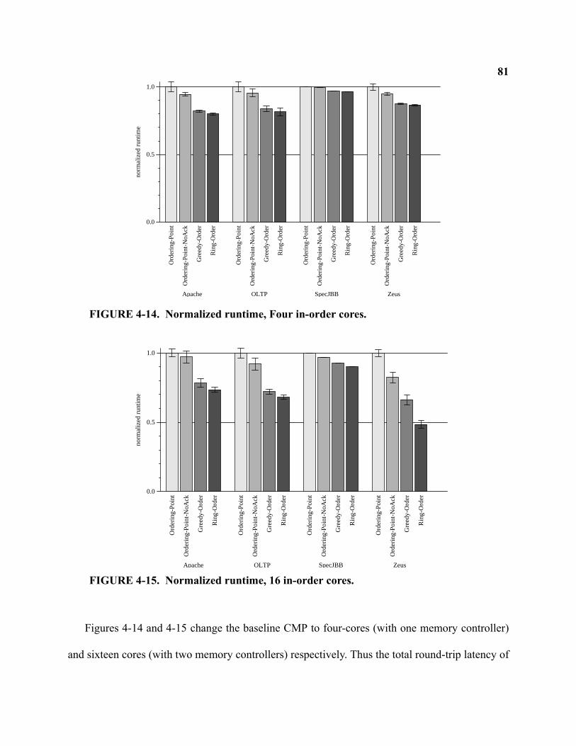
81
Figures 4-14 and 4-15 change the baseline CMP to four-cores (with one memory controller)
and sixteen cores (with two memory controllers) respectively. Thus the total round-trip latency of
0.0
0.5
1.0
norm
aliz
ed r
untim
e
Ord
erin
g-P
oint
Ord
erin
g-P
oint
-NoA
ck
Gre
edy-
Ord
er
Rin
g-O
rder
Apache
Ord
erin
g-P
oint
Ord
erin
g-P
oint
-NoA
ck
Gre
edy-
Ord
er
Rin
g-O
rder
OLTP
Ord
erin
g-P
oint
Ord
erin
g-P
oint
-NoA
ck
Gre
edy-
Ord
er
Rin
g-O
rder
SpecJBB
Ord
erin
g-P
oint
Ord
erin
g-P
oint
-NoA
ck
Gre
edy-
Ord
er
Rin
g-O
rder
Zeus
FIGURE 4-14. Normalized runtime, Four in-order cores.
0.0
0.5
1.0
norm
aliz
ed r
untim
e
Ord
erin
g-P
oint
Ord
erin
g-P
oint
-NoA
ck
Gre
edy-
Ord
er
Rin
g-O
rder
Apache
Ord
erin
g-P
oint
Ord
erin
g-P
oint
-NoA
ck
Gre
edy-
Ord
er
Rin
g-O
rder
OLTP
Ord
erin
g-P
oint
Ord
erin
g-P
oint
-NoA
ck
Gre
edy-
Ord
er
Rin
g-O
rder
SpecJBB
Ord
erin
g-P
oint
Ord
erin
g-P
oint
-NoA
ck
Gre
edy-
Ord
er
Rin
g-O
rder
Zeus
FIGURE 4-15. Normalized runtime, 16 in-order cores.
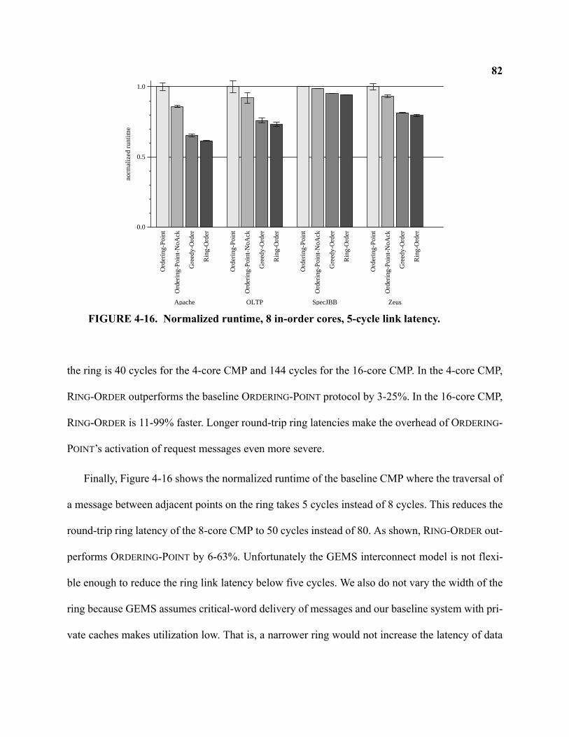
82
the ring is 40 cycles for the 4-core CMP and 144 cycles for the 16-core CMP. In the 4-core CMP,
RING-ORDER outperforms the baseline ORDERING-POINT protocol by 3-25%. In the 16-core CMP,
RING-ORDER is 11-99% faster. Longer round-trip ring latencies make the overhead of ORDERING-
POINT’s activation of request messages even more severe.
Finally, Figure 4-16 shows the normalized runtime of the baseline CMP where the traversal of
a message between adjacent points on the ring takes 5 cycles instead of 8 cycles. This reduces the
round-trip ring latency of the 8-core CMP to 50 cycles instead of 80. As shown, RING-ORDER out-
performs ORDERING-POINT by 6-63%. Unfortunately the GEMS interconnect model is not flexi-
ble enough to reduce the ring link latency below five cycles. We also do not vary the width of the
ring because GEMS assumes critical-word delivery of messages and our baseline system with pri-
vate caches makes utilization low. That is, a narrower ring would not increase the latency of data
0.0
0.5
1.0
norm
aliz
ed r
untim
e
Ord
erin
g-P
oint
Ord
erin
g-P
oint
-NoA
ck
Gre
edy-
Ord
er
Rin
g-O
rder
Apache
Ord
erin
g-P
oint
Ord
erin
g-P
oint
-NoA
ck
Gre
edy-
Ord
er
Rin
g-O
rder
OLTPO
rder
ing-
Poi
nt
Ord
erin
g-P
oint
-NoA
ck
Gre
edy-
Ord
er
Rin
g-O
rder
SpecJBB
Ord
erin
g-P
oint
Ord
erin
g-P
oint
-NoA
ck
Gre
edy-
Ord
er
Rin
g-O
rder
Zeus
FIGURE 4-16. Normalized runtime, 8 in-order cores, 5-cycle link latency.
83messages and our observed utilizations for 80-byte links (2-4%) would not result in significant
queuing delay with 40-byte or narrower links.
4.4.5 Summary of Evaluation
The following list summarizes some of the key findings from our evaluation of ORDERING-
POINT, GREEDY-ORDER, and RING-ORDER:
• RING-ORDER performs the fastest of all the evaluated protocols. In the baseline CMP with
eight in-order cores, it performed up to 47% faster than even the optimized ORDERING-POINT-
NOACK. However RING-ORDER either performs the same as GREEDY-ORDER or only offers
modest improvement.
• RING-ORDER offered stable performance by avoiding liveness issues that stem from protocols
using Nacks or retries. On the other hand, we demonstrated clear situations where pathologi-
cal retry scenarios occurred in our simulations of GREEDY-ORDER.
• Sensitivity studies show that out-of-order cores diminish the performance advantage of RING-
ORDER. However, increasing ring latency widens the performance gap between the stable
ORDERING-POINT and RING-ORDER protocols.
4.5 Future Work
This section discusses some areas of future work for the ring-based coherence techniques dis-
cussed in this chapter.
844.5.1 Reliability
Reliability is projected to become a serious architectural design issue as devices continue to
scale. One avenue of future work extends RING-ORDER to handle lost or corrupt messages at the
ring level. Coherence protocols typically assume that the underlying interconnect reliably delivers
messages. With both permanent and transient faults increasing with technology scaling [25], reli-
ability becomes a greater concern. Packet-switched interconnects may implement reliable mes-
sage delivery by a utilizing a combination of strong error-detection (such as a CRC code) and
link-level retransmission [39]. A physical ring, on the other hand, may implement very simple
routers with no link-level handshaking to detect and correct from errors through retransmission.
Prior SCI implementations of ring systems [53] handled transient message errors by checking
every transmission at the sender of the message. This scheme requires all messages to traverse the
entire ring. In our three protocols, all request messages indeed traverse the ring and can be
checked by the sender. Moreover, response messages in ORDERING-POINT and GREEDY-ORDER
have a specific destination. Thus in these protocols, the ring can deliver response messages to
their intended destination but also return the message to the sender to check the message’s integ-
rity (and resend if necessary). However, in RING-ORDER, checking the token-carrying response
messages at the sender may be problematic and warrants further investigation. Response mes-
sages do not have a specific destination and can be used by any node until the furthest destination
is reached. In essence, each hop of a message is sent from a node to the next adjacent node. As
such, source-based message checking would not only result in traffic and latency overhead, but
correctness could be compromised if extra tokens were unintentionally injected into the system.
Fortunately token counting has been shown to offer favorable properties in implementing a sys-
tem that is resilient to lost of corrupted messages at the protocol level instead of the link-level
85[101, 43]. Adapting RING-ORDER to handle lost coherence messages could help create a system
more tolerant of certain errors.
4.5.2 Embedding Ring Protocols in Hierarchy
The protocols discussed and developed in this chapter assume no hierarchy. However deploy-
ing a ring-based CMP may require interacting with an existing system-level interconnect to create
larger, hierarchical systems such as a Multiple-CMP. Multiple-CMP coherence is addressed in
Chapter 5, however it does not use ring-based protocols.
Embedding a ring-based protocol into a hierarchy would require an interface between the ring
coherence protocol, and the system-level coherence protocol. Like prior hierarchical systems such
as the Sun Wildfire [54], the interface would interact on the ring protocol like another processing
element. Nonetheless, we identify several unique challenges in adapting ring protocols to operate
in a higher-level, non-ring protocol.
The system-level protocol may either require a snoop response or an invalidate acknowledge-
ment on behalf of the entire CMP. GREEDY-ORDER can generate such a response under the
assumption that the system-level interconnect does not have a synchronous response requirement.
If, however, the system-level interconnect does require a snoop response within a fixed time, then
unbounded retries in GREEDY-ORDER violate this requirement. Fortunately, ORDERING-POINT and
RING-ORDER have upper-bounds on the time of a request. Acknowledging a system-level invali-
date message also presents difficulties for RING-ORDER and ORDERING-POINT. In particular,
RING-ORDER currently offers no snoop response if the CMP contains no tokens. One possible
extension to this protocol would indeed collect snoop responses such that the interface can deter-
86mine if the CMP contains zero tokens. Finally, the interface between the protocols must determine
when a system-level request is required.
4.5.3 Hierarchical Ring Protocols
Designing a hierarchy of rings is an attractive option towards increasing scalability to larger
numbers of cores. A Multiple-CMP system, for example, can connect CMPs in a ring topology
where each CMP itself also implements a ring. Another option being considered by Intel is build-
ing a hierarchy of rings within a single, many-core CMP [64].
Extending ring protocols to a hierarchy of rings is not straightforward. For example, GREEDY-
ORDER must collect a combined snoop response from the entire system when requesting a block
for exclusive access. Furthermore, a hierarchy may increase performance stability problems
because pathological requests within one ring level may starve out requests from a different ring
level. ORDERING-POINT can potentially extend to a hierarchy of rings by using a separate ordering
point at each ring level. Doing so will only increase the overheads of accessing the various order-
ing points.
RING-ORDER may offer an attractive approach to implementing non-directory coherence in a
hierarchy of rings. Token counting guarantees correctness and the global state of the system can
be inferred from the token count (i.e., all tokens existing within a ring level ensures no sharer
exists in a different level). One intriguing possibility in extending RING-ORDER treats the hierar-
chical of rings as a single, logical ring. Then, small filters placed at the interfaces between ring
levels can create shortcuts to increase performance in the common case by exploiting the hierar-
chy. For example, request messages can fan out when advantageous, and response messages can
bypass inner rings where there is not request outstanding.
874.6 Related Work
Barroso et al. [17, 18] developed a snooping protocol for SMP systems using a slotted ring,
which served as the basis of our greedily ordered protocol. They compared their snooping imple-
mentation against a directory-based ring protocol and a split-transaction bus, finding the snoop-
ing-on-rings approach preferable. We build upon the work of Barroso et al. by extending and
applying the protocol to a CMP, classifying snooping ring protocols based on ordering, comparing
it to a ring protocol that uses an ordering point, and comparing it to our newly developed RING-
ORDER protocol.
IBM’s Power4 [131] and Power5 [119] both use a protocol similar to GREEDY-ORDER [82].
One difference between GREEDY-ORDER and the IBM protocols is that memory in the IBM sys-
tems do not contain owner bits and do not participate in the combined response. Instead, the
requestor resends the combined snoop response on the ring. If no other cache acknowledged the
request in the combined response, the memory controller sends the data (which it prefetched when
observing the initial request). If the combined response indicates a coherence conflict, the node
instead issues a retry. To explicitly detect a conflict, whenever a node acknowledges a request and
sends data, it remembers the address in a table until cleared by the combined response that the
winning requestor resends. In contrast, our GREEDY-ORDER protocol uses owner bits and a mem-
ory interface cache to reduce memory latency and bandwidth in a CMP. In doing so, memory par-
ticipates in the combined response such that resending it, and explicitly detecting coherence
conflict with an extra table, is unnecessary.
Strauss et al. [124] present flexible snooping for optimizing performance and power in a sys-
tem using an embedded ring among bus-based CMPs. The protocol is similar to the IBM Power5
88and GREEDY-ORDER except that they selectively and predictively change when request messages
are forwarded to the next CMP. All of our protocols immediately forward a request message on
the ring before performing the snoop (eager forwarding) for maximum performance because
snoops parallelize. In contrast, Strauss et al. selectively and predictively do the opposite by first
performing a snoop and then forwarding the request to the next node on the ring (lazy forward-
ing), thereby potentially saving power. One consequence of this approach in a greedy ordered pro-
tocol is that a separate response message trails the request message whenever eagerly forwarded.
The GREEDY-ORDER protocol we model instead uses bandwidth-efficient response bits that fol-
low the request by a fixed number of cycles. Our work focuses on the ordering of requests on a
ring, eliminating the retries used by Strauss et al., and targets a CMP system. Nonetheless, their
forwarding strategy applies especially well to RING-ORDER because our protocol does not need an
expensive combined response message for every eagerly forwarded request.
The IBM Cell processor [61] uses a ring-based interconnect for transferring data between the
main core and the eight “synergistic processing elements” (SPEs). A tree-based centralized arbiter
determines when the SPEs access the ring to transfer data. We do not assume centralized arbitra-
tion for accessing the ring, although if one were present, it could be used for coherence ordering.
Since each individual SPE has its own private memory with separate addressing, the Cell inter-
connect is optimized for DMA-like operations rather than cache coherence at the line level.
The Scalable Coherence Interface (SCI) [53] is based on a register-insertion ring and used a
distributed directory-based protocol. Several systems were built with the SCI including the
Sequent STiNG system [89]. The SCI protocol does not exploit the ordering properties of a ring
and requires many messages to manipulate the doubly linked list of sharers. For example, obtain-
89ing a shared copy of data and updating the list of sharers requires four ring traversals. In contrast,
for all of our protocols, getting a shared copy requires only a single request message and a single
response message.
The Kendall Square Research KSR-1 [27, 47] used a hierarchy of slotted unidirectional rings
for cache coherence. In the KSR, a request is always lazily forwarded—a message visits a node,
performs the snoop operation, and only then is forwarded to the next node. Our protocols parallel-
ize the snoops by eagerly forwarding requests immediately to the next node before performing the
snoop. We fail to find the specific strategy the KSR used for handling coherence races. We sus-
pect that by not performing snoops in parallel, it is able to construct a linked chain of requests
because the searches are slow and can carry information about previous snoops.
Chung et al. [35] also proposed a snooping protocol for SMP systems based on register-inser-
tion rings. It too is greedily ordered and uses retries to handle conflict. Oi et al. [107] developed a
cache coherence protocol that operates on bidirectional rings for SMPs. Because bidirectional
rings have even less order than unidirectional rings, they use both retries and an ordering point.
The Hector SMP system used a hierarchy of rings and a write-update protocol with filters [41].
We only considered write-invalidate protocols in this work.
4.7 Conclusion
Rings offer an interconnect with short point-to-point links, distributed control, and ordering
properties exploitable by a coherence protocol. However, a ring does not provide the same order-
ing as a logical bus. In this chapter, we developed and classified snooping ring protocols based on
how coherence requests are ordered. The ORDERING-POINT protocol establishes an ordering point
to recreate the total order provided by a bus, but it is inefficient with latency and bandwidth. The
90GREEDY-ORDER protocol offers lower latency, but an unbounded number of retries are used to
resolve conflicts. Our new type of ring protocol, RING-ORDER, offers the best of ORDERING-POINT
(good performance stability) and GREEDY-ORDER (good average performance). Furthermore,
RING-ORDER does not require a synchronous snoop response, potentially easing design complex-
ity and verification, and potentially improving performance with its relaxed timing.
91Chapter 5
Coherence for Multiple-CMP Systems
Creating larger, more-capable systems from commodity hardware has shown to be cost effec-
tive [143] and commercially successful. The majority of prior machines integrated many single-
core processors to create cache-coherent multiprocessors.
Unlike prior multiprocessors built using single-core processors, Multiple-CMP systems (or
M-CMPs) use a CMP as the basic building block. In the short term, vendors will continue to build
modest-sized M-CMPs that continue to support a single, logically shared memory. However the
techniques for doing so present different tradeoffs. This chapter explores coherence for M-CMP
systems by proposing and comparing two alternative techniques. The first technique, Directory-
CMP, uses a hierarchy of directory protocols to enable a highly scalable system. The second tech-
nique, TokenCMP, applies token coherence [93] to reduce complexity and improve performance
while still enabling modest M-CMP scaling.
5.1 Multiple-CMP Cache Coherence
A Multiple-CMP system combines many CMP chips together to form a larger, shared memory
system. These systems will require mechanisms to keep caches coherent both within CMPs and
between CMPs. Figure 5-1 illustrates the issues in M-CMP coherence. One naive option for
implementing cache-coherence in an M-CMP system treats the system as completely flat by mak-
ing no distinction between an off-chip cache and an on-chip cache. This approach, however, will
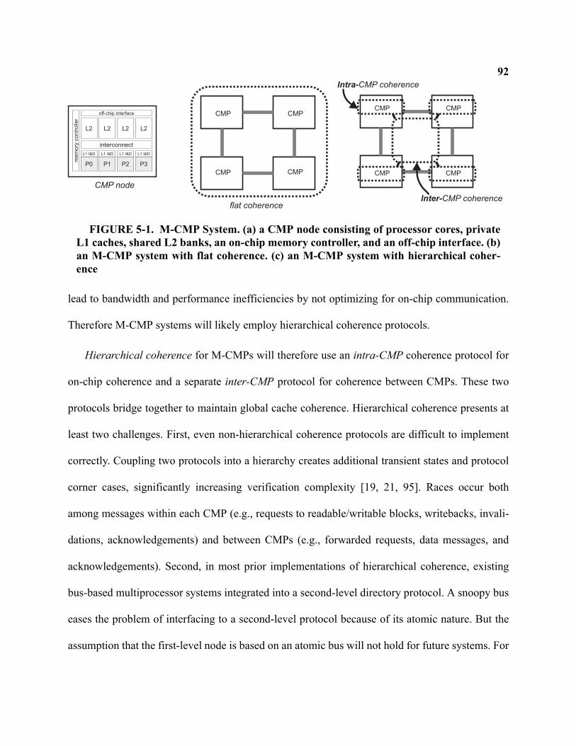
92
lead to bandwidth and performance inefficiencies by not optimizing for on-chip communication.
Therefore M-CMP systems will likely employ hierarchical coherence protocols.
Hierarchical coherence for M-CMPs will therefore use an intra-CMP coherence protocol for
on-chip coherence and a separate inter-CMP protocol for coherence between CMPs. These two
protocols bridge together to maintain global cache coherence. Hierarchical coherence presents at
least two challenges. First, even non-hierarchical coherence protocols are difficult to implement
correctly. Coupling two protocols into a hierarchy creates additional transient states and protocol
corner cases, significantly increasing verification complexity [19, 21, 95]. Races occur both
among messages within each CMP (e.g., requests to readable/writable blocks, writebacks, invali-
dations, acknowledgements) and between CMPs (e.g., forwarded requests, data messages, and
acknowledgements). Second, in most prior implementations of hierarchical coherence, existing
bus-based multiprocessor systems integrated into a second-level directory protocol. A snoopy bus
eases the problem of interfacing to a second-level protocol because of its atomic nature. But the
assumption that the first-level node is based on an atomic bus will not hold for future systems. For
P0 P1 P2 P3
L2 L2 L2 L2
L1 I&D L1 I&D L1 I&D L1 I&D
me
mo
ryco
ntr
olle
r
interconnect
off-chip interface CMP CMP
CMPCMP
CMP CMP
CMPCMP
flat coherence
CMP node
Inter-CMP coherence
Intra-CMP coherence
FIGURE 5-1. M-CMP System. (a) a CMP node consisting of processor cores, privateL1 caches, shared L2 banks, an on-chip memory controller, and an off-chip interface. (b)an M-CMP system with flat coherence. (c) an M-CMP system with hierarchical coher-ence
93example, both the Piranha [20] and Sun Niagara [76] CMPs implement on-chip cache coherence
with a directory-like protocol operating on a crossbar interconnect. Future systems will require
even more scalable interconnects such as a packet-switched grid.
In this chapter, we explore hierarchical coherence techniques for M-CMPs. In Section 5.2, we
develop a protocol that uses directory protocols for both intra-CMP and inter-CMP coherence. In
Section 5.3, we extend token coherence to an M-CMP system by developing TokenCMP.
TokenCMP provides coherence in a manner that is flat for correctness, but direct and hierarchical
for performance. DirectoryCMP and TokenCMP are evaluated with full-system simulation in
Section 5.4. Related work is presented in Section 5.5, a discussion of future work in Section 5.6.,
and we conclude in Section 5.7.
5.2 DirectoryCMP: A 2-level directory protocol for M-CMPs
We develop a hierarchical protocol that uses directories at both levels called DirectoryCMP.
By employing directories, we maximize scalability opportunities by supporting large numbers of
cores per chip and large numbers of chips. However as we will see, a primary cost is both imple-
mentation complexity and, like any directory protocol, indirection overhead. DirectoryCMP does
not assume any ordering of the interconnection networks either within a CMP or between CMPs.
This enables completely unordered networks, banked caches and controllers, and other intercon-
nect optimizations such as different classes of wires1 [31].
1. The work presented in [31] actually uses the DirectoryCMP implementation as a vehicle for evaluating their interconnect opti-
mizations.
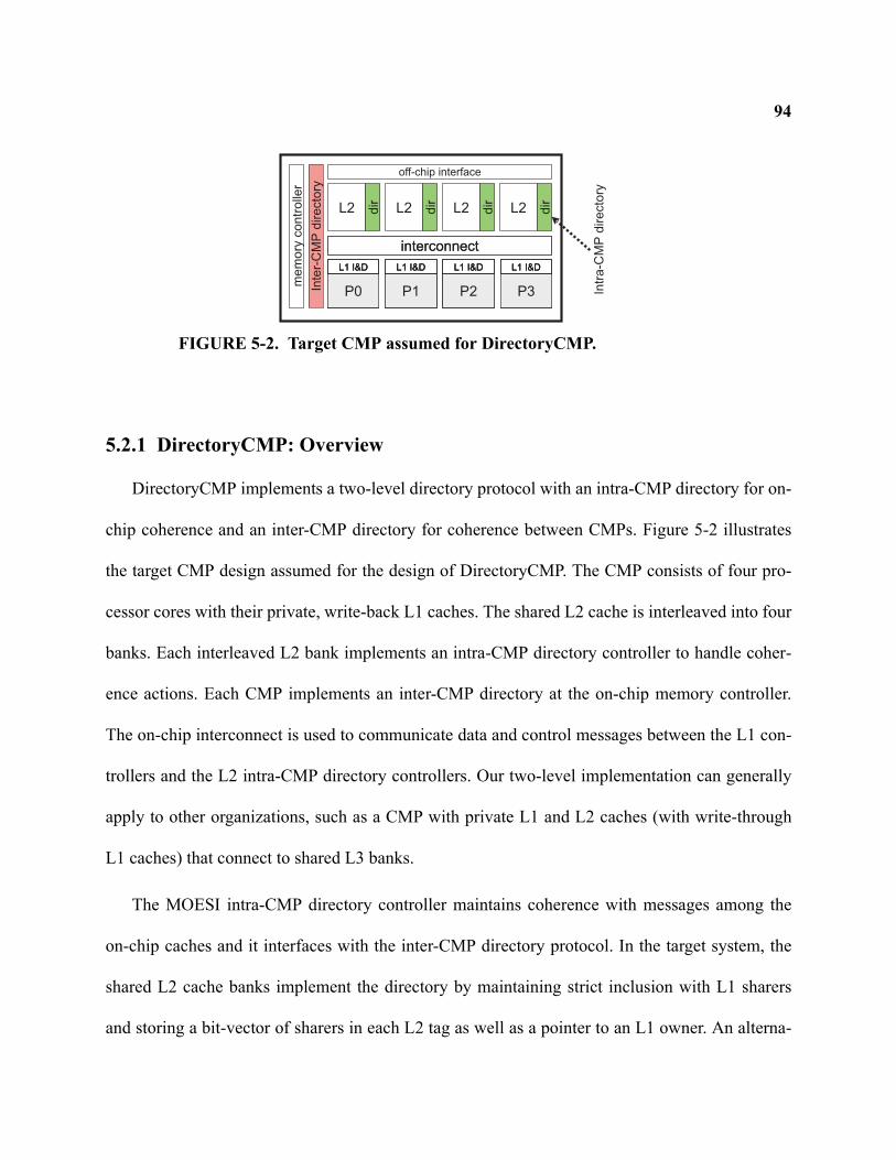
94
5.2.1 DirectoryCMP: Overview
DirectoryCMP implements a two-level directory protocol with an intra-CMP directory for on-
chip coherence and an inter-CMP directory for coherence between CMPs. Figure 5-2 illustrates
the target CMP design assumed for the design of DirectoryCMP. The CMP consists of four pro-
cessor cores with their private, write-back L1 caches. The shared L2 cache is interleaved into four
banks. Each interleaved L2 bank implements an intra-CMP directory controller to handle coher-
ence actions. Each CMP implements an inter-CMP directory at the on-chip memory controller.
The on-chip interconnect is used to communicate data and control messages between the L1 con-
trollers and the L2 intra-CMP directory controllers. Our two-level implementation can generally
apply to other organizations, such as a CMP with private L1 and L2 caches (with write-through
L1 caches) that connect to shared L3 banks.
The MOESI intra-CMP directory controller maintains coherence with messages among the
on-chip caches and it interfaces with the inter-CMP directory protocol. In the target system, the
shared L2 cache banks implement the directory by maintaining strict inclusion with L1 sharers
and storing a bit-vector of sharers in each L2 tag as well as a pointer to an L1 owner. An alterna-
L2 L2 L2 L2
me
mo
ryco
ntr
olle
rP0
L1 I&D
P1
L1 I&D
P2
L1 I&D
P3
L1 I&D
interconnect
P0
L1 I&D
P0
L1 I&D
P1
L1 I&D
P1
L1 I&D
P2
L1 I&D
P2
L1 I&D
P3
L1 I&D
P3
L1 I&D
interconnect
off-chip interface
Inte
r-C
MP
dir
ecto
ry
dir
dir
dir
dir
Intr
a-C
MP
dir
ecto
ry
FIGURE 5-2. Target CMP assumed for DirectoryCMP.
95tive directory organization may duplicate the tags of all on-chip caches, like the Sun Niagara [76]
or Compaq Piranha [20], or implement a separate directory structure that uses an inclusive cache
of directory entries. Our specification of DirectoryCMP is general enough to handle most of these
first-level directory organizations with only minor changes to the states and actions.
DirectoryCMP implements inter-CMP coherence with directories at each of the memory con-
trollers. These directories track which CMP nodes cache a block, but not which caches within the
CMP hold the block. The inter-CMP directory maintains coherence with messages between itself
and the appropriate intra-CMP directory at each CMP.
The intra- and inter-CMP directories and protocols cooperate to maintain global M-CMP
coherence. An L1 miss sends a coherence request to the appropriate L2 bank. Depending on the
state of the block (if cached) along with the state of any pending requests, the L2 bank may
directly respond to the request, may forward the request to local L1 caches, may issue a second-
level request to the inter-CMP directory (located at the home memory controller for the block), or
may stall on the request. As responses return through the hierarchical network, they update the
appropriate cache and directory state.
The following sub-sections further expand on DirectoryCMP.
5.2.2 DirectoryCMP: MOESI Intra-CMP Protocol
We now elaborate on the specifics of the intra-CMP Protocol implemented at the L2 control-
lers. DirectoryCMP implements all MOESI states at both protocol levels. All L1 coherence
requests issue to the L2 controller where the state is queried by accessing the matching L2 tag and
auxiliary directory structure (if used). The stable states at the L2 controller are shown in Table 5-
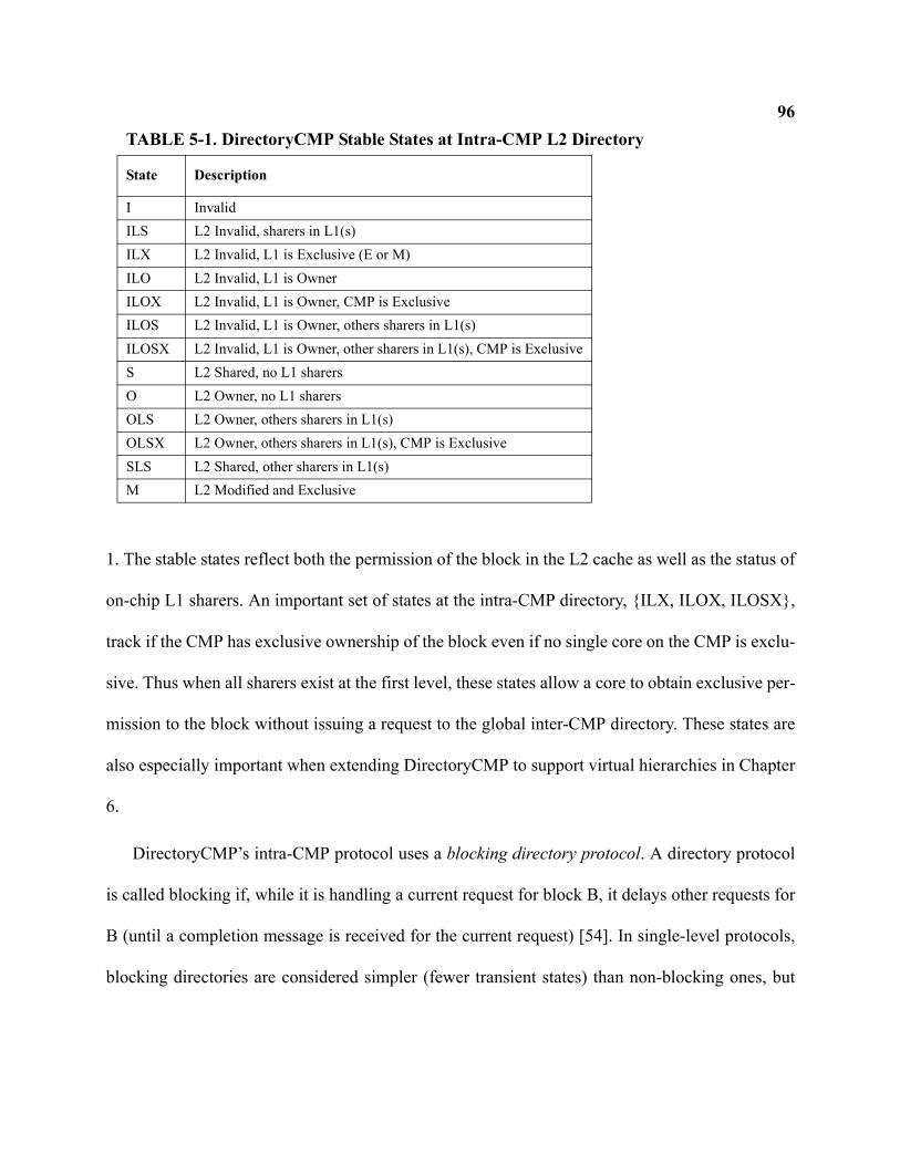
96
1. The stable states reflect both the permission of the block in the L2 cache as well as the status of
on-chip L1 sharers. An important set of states at the intra-CMP directory, {ILX, ILOX, ILOSX},
track if the CMP has exclusive ownership of the block even if no single core on the CMP is exclu-
sive. Thus when all sharers exist at the first level, these states allow a core to obtain exclusive per-
mission to the block without issuing a request to the global inter-CMP directory. These states are
also especially important when extending DirectoryCMP to support virtual hierarchies in Chapter
6.
DirectoryCMP’s intra-CMP protocol uses a blocking directory protocol. A directory protocol
is called blocking if, while it is handling a current request for block B, it delays other requests for
B (until a completion message is received for the current request) [54]. In single-level protocols,
blocking directories are considered simpler (fewer transient states) than non-blocking ones, but
TABLE 5-1. DirectoryCMP Stable States at Intra-CMP L2 Directory
State Description
I InvalidILS L2 Invalid, sharers in L1(s)ILX L2 Invalid, L1 is Exclusive (E or M)ILO L2 Invalid, L1 is OwnerILOX L2 Invalid, L1 is Owner, CMP is ExclusiveILOS L2 Invalid, L1 is Owner, others sharers in L1(s)ILOSX L2 Invalid, L1 is Owner, other sharers in L1(s), CMP is ExclusiveS L2 Shared, no L1 sharersO L2 Owner, no L1 sharersOLS L2 Owner, others sharers in L1(s)OLSX L2 Owner, others sharers in L1(s), CMP is ExclusiveSLS L2 Shared, other sharers in L1(s)M L2 Modified and Exclusive
97forgo some concurrency. As we will see in Section 5.2.4, blocking directories in a two-level pro-
tocol help manage races between the inter- and intra-CMP protocols.
A request from an on-chip processor core causes the intra-CMP directory to enter a transient
busy state. The complete listing of all 63 states at DirectoryCMP’s L2/intra-CMP controller is
given in Table B-1 of Appendix B. If the request finds the L2 controller in a transient state for the
same cache line address, the request blocks. Strategies for implementing request blocking are dis-
cussed in Section 5.2.5.
A handled request either causes the L2 controller to directly respond with data, generate for-
ward and/or invalidate messages to local L1 caches, or issue the request to the global inter-CMP
directory. When the L1 requestor completes the coherence request, it sends a completion message
to the intra-CMP directory to unblock. This both updates the directory state with new sharer infor-
mation and causes it to enter a stable state. If other requests are blocked for the same cache line
address, the next pending request is then handled (further discussed in Section 5.2.5).
An intra-CMP GETS request completes when it receives the data from either the L2 cache or
a neighboring L1 cache. An intra-CMP GETM completes when it receives the data and also
receives an ACK from all the on-chip sharers. The L2 controller passes the number of sharers in
the forwarded request to the local Owner, which in turn passes the count in the returned data
response. The L1 controller of the requestor collects and counts acknowledgements and sends a
completion message to the L2 bank when all Acks have been received.
DirectoryCMP uses three-phase writebacks [54] to order the writeback operation and thereby
prevent races with other requests. In a three-phase writeback, the controller sends a PUT message
to the directory. The PUT message also indicates if the replacement block is a shared, owned, or
98exclusive. The directory enters a busy state to prevent coherence races and then responds with an
acknowledgement. Finally, the controller sends the data to the directory upon receiving the ack. If
non-inclusive L2 caching is employed (i.e., directory state is not stored in inclusive L2 tags), the
acknowledgement message from the intra-CMP L2 directory to the L1 can also indicate if the L1
should send the data because it could hold the only on-chip copy (even if the L1 was in the S
state). But in our target system that stores directory state in L2 tags, replacing a tag with active
directory state must invalidate the L1 sharers before completing the replacement operation. This
entails sending invalidation messages, collecting acknowledgements, and potentially receiving
dirty data from an exclusive L1 sharer. If an owned or exclusive PUT request finds the directory
busy due to a subsequent request or forward, the directory sends a negative acknowledgement
(Nack). In all likelihood, the replacing cache will receive a forwarded request, which it handles,
and then completes the victimization process.
An implementor might chose to instead implement the intra-CMP protocol with MESI states
instead of the full MOESI states. This especially makes sense for an inclusive, shared L2 cache
because the cache itself can act as the implicit owner of the block for any shared request. More-
over, if directory state is stored in L2 cache tags, this would reduce the state overhead in tags by
eliminating the pointer to an L1 owner. Surprisingly dropping the O-state has minimal impact on
our protocol design and performance because we use blocking directories in conjunction with
completion messages. When an L1 downgrades from M on behalf of an on-chip GETS, the com-
pleting requestor simply sends the data to the L2 cache along with the completion message. We
chose to implement the full MOESI states because our design functions with and without inclu-
sive L2 caches.
99Finally we consider the virtual network requirements of DirectoryCMP to prevent protocol
deadlock. The inter-CMP protocol requires a separate virtual network for request messages,
response messages, and completion messages. Three-phase writebacks preclude the need for any
additional virtual networks for replacement operations.
5.2.3 DirectoryCMP: MOESI Inter-CMP Protocol
The inter-CMP protocol operates in much the same was as the intra-CMP protocol. The direc-
tory state is stored in DRAM and accessed at the memory/directory controller. Each directory
entry contains a full-map vector of sharers and a pointer to the owning or exclusive CMP. Impor-
tantly, the directory points to CMPs and not individual cores. Thus for a system comprised of four
CMPs where each CMP consists of eight cores, the required directory state in DRAM is only six
bits (4-bit vector of sharers and 2-bit pointer to owner).
Requests received from CMPs cause the global directory to access the directory state and
either return data and/or issue forward and invalidate messages to other CMPs. The global direc-
tory also blocks subsequent requests for the same memory block until unblocked by a completion
message from the requestor currently being serviced.
When the L2 intra-CMP directory receives an invalidate or forward from the inter-CMP direc-
tory, it must take and complete the required actions before acknowledging the request or returning
data. For example, an inter-CMP invalidate must generate intra-CMP invalidate messages to local
L1 sharers or potentially forward a request to an L1 owner. Acknowledgement messages are col-
lected and counted from L1 sharers before sending a chip-wide acknowledgement.
100Like the intra-CMP protocol, DirectoryCMP’s inter-CMP protocol also employs three-phase
writebacks and has the same virtual network requirements.
5.2.4 DirectoryCMP: Inter-Intra CMP Races
A key challenge for DirectoryCMP, and any two-level directory protocol, is resolving races.
Not only can races occur within the inter-CMP and intra-CMP protocols, but between the proto-
cols. This section presents the strategy we developed for resolving races in DirectoryCMP. We are
not aware of any other published literature that describes race-handling mechanisms in a two-
level directory protocol.
The blocking inter- and intra-CMP directories help manage racing requests in the same proto-
col. For example, the intra-CMP directory blocks on receiving a GETM request from core P1. If
core P2 then issues a request for the same block and find the directory busy for the same address,
the request blocks so that it cannot interfere or race with the initial request.
Naively implementing blocking in a two-level directory protocol, however, leads to deadlock
because of possible cyclic dependencies at level-one directories. Figure 5-3 shows an example of
this type of deadlock where P1’s forwarded request from the level-two directory finds a depen-
dent level-one directory already blocked on P4’s request.
The protocol can avoid deadlock by always handling second-level inter-CMP messages at
first-level intra-CMP directories. But this may cause an explosion of states when a second-level
message can interrupt any pending first-level intra-CMP operation. We instead establish a smaller
set of safe states that include all stable states and a subset of the transient states. A safe state can
immediately handle any second-level message, otherwise the message must wait until a safe state
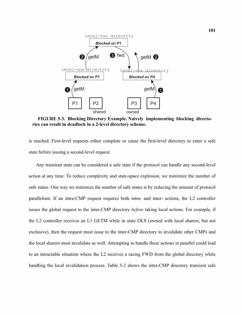
101
is reached. First-level requests either complete or cause the first-level directory to enter a safe
state before issuing a second-level request.
Any transient state can be considered a safe state if the protocol can handle any second-level
action at any time. To reduce complexity and state-space explosion, we minimize the number of
safe states. One way we minimize the number of safe states is by reducing the amount of protocol
parallelism. If an intra-CMP request requires both intra- and inter- actions, the L2 controller
issues the global request to the inter-CMP directory before taking local actions. For example, if
the L2 controller receives an L1 GETM while in state OLS (owned with local sharers, but not
exclusive), then the request must issue to the inter-CMP directory to invalidate other CMPs and
the local sharers must invalidate as well. Attempting to handle these actions in parallel could lead
to an intractable situation where the L2 receives a racing FWD from the global directory while
handling the local invalidation process. Table 5-2 shows the intra-CMP directory transient safe
P1
Level-one directory
P4
Level-one directory
Level-two directory
getM getM
getM fwd getM
1 1
2 23
Blocked on P1
Blocked on P1
Blocked on P4
P2 P3
shared owned
FIGURE 5-3. Blocking Directory Example. Naively implementing blocking directo-ries can result in deadlock in a 2-level directory scheme.
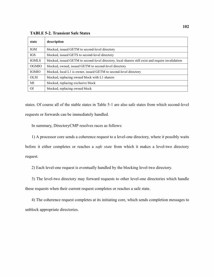
102
states. Of course all of the stable states in Table 5-1 are also safe states from which second-level
requests or forwards can be immediately handled.
In summary, DirectoryCMP resolves races as follows:
1) A processor core sends a coherence request to a level-one directory, where it possibly waits
before it either completes or reaches a safe state from which it makes a level-two directory
request.
2) Each level-one request is eventually handled by the blocking level-two directory.
3) The level-two directory may forward requests to other level-one directories which handle
these requests when their current request completes or reaches a safe state.
4) The coherence request completes at its initiating core, which sends completion messages to
unblock appropriate directories.
TABLE 5-2. Transient Safe States
state description
IGM blocked, issued GETM to second-level directoryIGS blocked, issued GETS to second-level directoryIGMLS blocked, issued GETM to second-level directory, local sharers still exist and require invalidationOGMIO blocked, owned, issued GETM to second-level directoryIGMIO blocked, local L1 is owner, issued GETM to second-level directoryOLSI blocked, replacing owned block with L1 sharersMI blocked, replacing exclusive blockOI blocked, replacing owned block
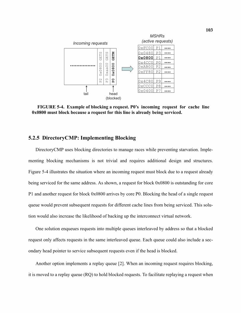
103
5.2.5 DirectoryCMP: Implementing Blocking
DirectoryCMP uses blocking directories to manage races while preventing starvation. Imple-
menting blocking mechanisms is not trivial and requires additional design and structures.
Figure 5-4 illustrates the situation where an incoming request must block due to a request already
being serviced for the same address. As shown, a request for block 0x0800 is outstanding for core
P1 and another request for block 0x0800 arrives by core P0. Blocking the head of a single request
queue would prevent subsequent requests for different cache lines from being serviced. This solu-
tion would also increase the likelihood of backing up the interconnect virtual network.
One solution enqueues requests into multiple queues interleaved by address so that a blocked
request only affects requests in the same interleaved queue. Each queue could also include a sec-
ondary head pointer to service subsequent requests even if the head is blocked.
Another option implements a replay queue [2]. When an incoming request requires blocking,
it is moved to a replay queue (RQ) to hold blocked requests. To facilitate replaying a request when
0x0800 P1
0x0480 P3
0x4CC0 P0
MSHRs
(active requests)
0xFC00 P1
0xFF80 P2
0x4C80 P9
0xAB00 P2
0xCCC0 P8
0x0400 P7
P00x0800GETM
P30xaa00GETS
P20x0800GETS
head(blocked)
Incoming requests
tail
FIGURE 5-4. Example of blocking a request. P0’s incoming request for cache line0x0800 must block because a request for this line is already being serviced.
104the directory unblocks for that address, the entries in the RQ are maintained as a linked list
according to cache line address. The head of the list is the MSHR entry for the request currently
being serviced for that address. When the current request finishes, it replays the next waiting
request in the RQ and updates pointers appropriately. The downside of this approach is that insert-
ing a new request into the RQ may require multiple pointer traversals, potentially making it more
difficult to incorporate into a pipelined coherence engine.
An alternative to blocking in single-level directory protocols uses protocol Nacks (negative
acknowledgements) [84] when a request encounters a directory already servicing a different
request for the given cache block. We did not explore this approach because of the complications
in dealing with a forwarded inter-CMP request at a busy intra-CMP directory. Furthermore, a
Nacking protocol may encounter pathological starvation scenarios in which a core’s request is
continually Nacked and retried. Starvation could especially be severe in a hierarchical protocol
where the arrival rate of intra-CMP requests can potentially be much higher than the arrival rate
of forwarded inter-CMP requests.
5.2.6 DirectoryCMP: Discussion
DirectoryCMP offers a highly scalable, hierarchical protocol for M-CMPs. To our knowledge,
it is the first detailed specification2, described in the academic literature, of a two-level directory
protocol. With its flexibility comes the cost of implementation complexity. In our published work
[95], model-checking DirectoryCMP was not feasible due to the state-space explosion. Further-
2. A SLICC-specified implementation of DirectoryCMP is available as part of the Wisconsin GEMS toolset [142]. The state-tran-
sition tables are too large to fit in this dissertation.
105more, even if model-checked, the structures for implementing correct blocking and request replay
add an additional level of complexity.
In the next section, we seek to reduce implementation complexity and to remove any indirec-
tion overheads of a directory protocol by applying token coherence to an M-CMP system.
5.3 TokenCMP: Flat for Correctness, Hierarchical for Performance
In this section, we develop the TokenCMP coherence protocol that is flat for correctness, but
hierarchical for performance. The separation of correctness and performance, enabled by token
coherence, allows us to build a system with reduced complexity yet with performance characteris-
tics comparable or better than conventional hierarchical protocols. In our previously published
work [95], we showed how a flat correctness substrate enabled the successful model checking of
TokenCMP3 whereas model checking DirectoryCMP was not feasible within reasonable space
and time limits. With a flat correctness substrate that successfully model checks, we then use per-
formance policies that exploit the hierarchy for improved performance and bandwidth. Section
5.3.1 details how we extend and apply the correctness of token coherence to an Multiple-CMP
system. Then in Section 5.3.2, we develop performance policies to exploit the hierarchy. Section
5.3.3 discusses more details about TokenCMP and Section 5.3.4 offers a qualitative comparison
of complexity between TokenCMP and DirectoryCMP.
3. Since the model checking portion of this work was performed by the other co-authors, we omit model checking from this dis-
sertation.
1065.3.1 TokenCMP: Flat Correctness Substrate
In token coherence as originally proposed (Section 2.2.6), tokens were passed to individual
nodes where each node was an entire uniprocessor. Since each uniprocessor node contains a pri-
vate cache hierarchy, it was assumed that maintaining correct coherence within a node used other,
simple mechanisms independent of the coherence protocol. Even in RING-ORDER of Chapter 4,
tokens were still passed to individual nodes on a CMP where each node consisted of a processor
core and its private cache hierarchy.
TokenCMP passes tokens to individual caches within a CMP. Moreover, individual caches
within each CMP hold tokens from the same global set of T tokens for each memory block. Using
a global set of tokens is key to making a flat correctness substrate. The alternative of using a sep-
arate set of T tokens for each CMP would result in the complexity we seek to avoid. Each cache in
the system—L1 data caches, L1 instruction caches, and L2 cache banks—essentially act like
“nodes” and holds tokens in their cache tags. Other structures that hold tokens may include auxil-
iary structures such as victim caches [70]. A block may be simultaneously cached in at most T
caches. Fortunately, doubling T to accommodate more individual caches only adds a single bit to
the token counts stored in cache tags and memory.
TokenCMP assumes write-allocate, write-back L1 caches4 so that token counting applies end-
to-end to ensure coherence safety. That is, a processor core may read a block if its L1 data (or
instruction) cache has at least one token; it may write a block if its L1 data cache has all the
tokens.
4. Supporting write-through L1/L2 caching is not obvious with TokenCMP since store permission must be obtained by acquiring
all the tokens. Extending TokenCMP to write-through L1/L2 caches is a topic of future work.
107TokenCMP performance policies, discussed in the following section, acquire tokens on behalf
of a core’s L1 read or write miss by issuing unordered transient requests. In the common case,
these requests succeed even without any ordering. In contrast, DirectoryCMP carefully orders
requests, manages coherence permissions, and orchestrates the movement of data by using both
intra- and inter-CMP ordering points (directories). While a TokenCMP performance policy can
also use directories and ordering points to order requests and orchestrate the movement of tokens,
doing so would result in the complexity that TokenCMP seeks to eliminate. With a correctness
substrate that guarantees both coherence safety and liveness, the performance policy can imple-
ment a flexible policy that does not need to track all possible races. With this flexibility comes the
potential for pathological livelock due to a transient request that continually miss in-flight tokens.
Like original token coherence, TokenCMP uses persistent requests to avoid pathological star-
vation and livelock when transient requests fail. A persistent request establishes a global order of
racing requests for a block and always succeeds. However implementing persistent requests
comes with cost. Once activated, a persistent request must remain active in the system until the
starving core acquires all the needed tokens. Then it deactivates the persistent request. Both the
activate and deactivate process are global operations that require a system-wide broadcast. More-
over, each cache in the system must maintain a table of activated persistent in case it receives a
token-carrying message after it receives the persistent activate message.
Rather than developing new hierarchical persistent request methods, we apply the original flat
arbitration schemes to maintain a flat, model-checkable correctness substrate. We review two
alternative approaches to implementing persistent requests in a Multiple-CMP system—central-
108ized and distributed. Each approach is invoked after some number of transient requests fail to
acquire the necessary tokens (transient request retries are discussed in Section 5.3.3).
Arbiter-based Activation. Extending the original arbiter-based persistent request mechanism to
M-CMPs is straightforward, but requires each cache, not just each node, to remember active per-
sistent requests. In arbiter-based activation, a starving core issues a request to the interleaved arbi-
ter for the given block address. The arbiter establishes a total order of persistent requests and
activates a request by broadcasting a PERSISTENTACTIVATE message to all cache controllers in
all CMPs. Upon receiving this message, a cache controller will respond with any tokens that it
possesses. A cache controller will also insert the block address into a table, sized to the number of
interleaved arbiters, that tracks outstanding persistent requests. Any tokens received by a cache
controller query the table to determine if a persistent request has been activated for some other
core. If so, the tokens are immediately forwarded to the starving core. Upon completing the per-
sistent request, a message is sent to the arbiter which then broadcasts a PERSISTENTDEACTIVATE
message to remove the block address from the tables.
Using arbiter-based persistent requests provides flat starvation avoidance in M-CMP systems.
Furthermore, the tables for storing active persistent requests are small (e.g., 384 bytes for 64 six-
byte entries) and directly addressed.
However simple, the arbiter-based activation mechanism lacks performance robustness. That
is, when performance gets bad, persistent requests tend to make it worse because the handoff from
one persistent request to the next requires an indirect deactivate/activate exchange with the arbi-
ter, increasing both latency and bandwidth consumption. Although this has little effect for well-
109tuned workloads, we seek an alternative mechanism that avoids surprises with more demanding
applications and can exploit some locality in a Multiple-CMP system.
Distributed Activation. The distributed activation scheme improves worst-case performance by
directly forwarding contended blocks to the core with the next active persistent request. More-
over, the distributed approach enhances the locality of CMPs by handing blocks off to cores
within a CMP before handing off to the next CMP.
In distributed activation, a starving core directly broadcasts a PERSISTENTACTIVATE mes-
sage to all system-wide coherence controllers and a PERSISTENTDEACTIVATE message to com-
plete a request. Each core’s L1 controller initiates at most one persistent request, and each
controller remembers these persistent requests in a content-addressable table (each table has one
entry per core). The table activates only the highest priority persistent request of those in the table
seeking the same block. When tokens for block B arrive, the controller searches the table for an
active persistent request for block B, and, if found, tokens forward to the starving core. When a
new persistent request for block B arrives, the controller inserts the incoming request to the table
and forwards any tokens to the active request (which may or may not be the newly received
request depending on the priority).
Priority among persistent requests is fixed by core number. When a cache receives a message
deactivating a persistent request, it clears the corresponding table entry. When a core deactivates
its own persistent request, its local table “marks” all valid entries for the same block by setting a
bit in the entry. A core is allowed to issue a persistent request only when no marked entries for the
desired block are present in its local persistent request table. The marking mechanism prevents a
core from continually issuing persistent requests that starve out another core. This approach is
110loosely based on FutureBus [130] arbitration, which uses a fixed priority but groups cores into
“waves” to prevent them from re-requesting bus access until all current wave members obtain
access. Thus this scheme prevents starvation, but is not necessarily fair because of the fixed prior-
ity based only on core number.
Distributed activation reduces the average persistent request latency by forwarding highly
contended blocks directly between cores. For example, let cores P1, P2, and P3 seek block B with
persistent requests. All three will remember each other’s requests, but activate only the highest
priority request, say, core P1’s. When P1 succeeds, it deactivates its request, activates P2’s
request, and sends block B to P2. When P2 is done, it sends block B directly to P3. In this way, the
distributed scheme provides a minimum latency hand-off on highly-contended blocks (e.g., hot
locks). Moreover, locality of block hand-off can be enhanced by simply fixing core priority so
that the least-significant bits vary for cores within a CMP and more-significant bits vary between
CMPs. In particular, with this approach, highly-contended spin locks tend to dynamically perform
much like complex hierarchical or reactive locks [87, 30].
5.3.2 TokenCMP: Hierarchical Performance Policies
In this section, we develop performance policies for modest-sized M-CMP systems that
exploit the physical hierarchy. By taking into account the hierarchy, the protocol should prefer
intra-CMP coherence actions to inter-CMP actions. For example, the protocol should reduce the
latency of a read miss by obtaining a copy of the data within the CMP instead of off-chip when-
ever possible. Furthermore, the protocol should not waste the bandwidth of inter-CMP coherence
when intra-CMP coherence will satisfy the coherence operation. A flat performance policy, like
TokenB [90], accomplishes neither latency nor bandwidth reduction in a Multiple-CMP system
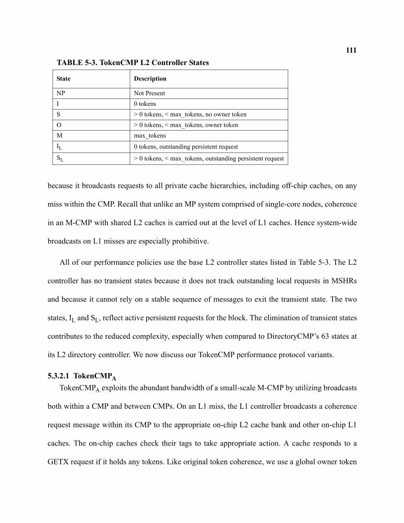
111
because it broadcasts requests to all private cache hierarchies, including off-chip caches, on any
miss within the CMP. Recall that unlike an MP system comprised of single-core nodes, coherence
in an M-CMP with shared L2 caches is carried out at the level of L1 caches. Hence system-wide
broadcasts on L1 misses are especially prohibitive.
All of our performance policies use the base L2 controller states listed in Table 5-3. The L2
controller has no transient states because it does not track outstanding local requests in MSHRs
and because it cannot rely on a stable sequence of messages to exit the transient state. The two
states, IL and SL, reflect active persistent requests for the block. The elimination of transient states
contributes to the reduced complexity, especially when compared to DirectoryCMP’s 63 states at
its L2 directory controller. We now discuss our TokenCMP performance protocol variants.
5.3.2.1 TokenCMPATokenCMPA exploits the abundant bandwidth of a small-scale M-CMP by utilizing broadcasts
both within a CMP and between CMPs. On an L1 miss, the L1 controller broadcasts a coherence
request message within its CMP to the appropriate on-chip L2 cache bank and other on-chip L1
caches. The on-chip caches check their tags to take appropriate action. A cache responds to a
GETX request if it holds any tokens. Like original token coherence, we use a global owner token
TABLE 5-3. TokenCMP L2 Controller States
State Description
NP Not PresentI 0 tokensS > 0 tokens, < max_tokens, no owner tokenO > 0 tokens, < max_tokens, owner tokenM max_tokensIL 0 tokens, outstanding persistent request
SL > 0 tokens, < max_tokens, outstanding persistent request
112to determine which cache sends data along with its tokens. An L1 cache responds to a local GETS
request, with a single token and data, if it possesses multiple tokens (even non-owner). This
allows a core to obtain data from an on-chip cache even if the global owner token is located off-
chip. An L1 cache only responds if it has multiple tokens so that it does not give away its last
token, thereby losing read permission. However an L2 cache will relinquish its last token to an
on-chip GETS requestor. If any cache possesses all tokens and has modified the data, it optimizes
for migratory sharing [37, 123] by transferring the data and all tokens.
If the L2 does not hold sufficient tokens to satisfy a local request, it then broadcasts the
request off-chip to other CMPs. A CMP responds to external GETM requests by returning all
tokens (and data if it holds the owner token). A CMP responds to external GETS requests only if
it holds the owner token. To reduce the latency of a future intra-CMP request, read responses
include C tokens (if possible), rather than the necessary 1 token, where C is the number of caches
on a CMP node. By including extra tokens in the off-chip response, future read requests within the
CMP can satisfy locally as described above. A cache may also respond to a read request with all T
tokens to optimize for migratory sharing.
5.3.2.2 TokenCMPBTokenCMPB is similar to TokenCMPA except that L1 misses first check the L2 cache before
initiating any broadcast operations. The L2 cache can act as an effective filter to reduce the
amount of on-chip broadcasts. The potential downside is that on-chip sharing between L1 caches
incurs a level of indirection.
In TokenCMPB, L1 misses first issue to the interleaved L2 bank instead of initiating a full on-
chip broadcast. Only if the request misses in the L2 cache does it invoke an on- and off-chip
broadcast. Since a substantial fraction of L1 misses are satisfied by the L2 cache, we expect to see
113a significant reduction of on-chip broadcasts. Reducing on-chip broadcasts can save power by
eliminating unnecessary tag lookups in the performance-sensitive L1 caches.
5.3.2.3 TokenCMPCTokenCMPC extends TokenCMPB with extra stable states at the L2 cache (IX, IS) as well as
approximating inclusion amongst L1 sharers. These states allow the L2 controller to further
reduce tag lookup and interconnect bandwidth by avoiding off-chip broadcasts for most on-chip
cache-to-cache transfers.
The IX state represents an invalid tag at the L2 cache but indicates that a local L1 sharer likely
holds the exclusive copy of the block (with all tokens). The IS state represents an invalid tag and
indicates that a local L1 sharer likely holds a shared copy (with extra tokens). Upon completing a
GETS (or GETM) request, the core updates the L2 bank by sending a non-token REGISTER-
SHARED (or REGISTEREXCLUSIVE) control message to the L2 controller, placing it in state IX or
IS. This message may also trigger a replacement of an L2 block. Off-chip transient requests or any
persistent request will clear the IX and IS states to I (Invalid).
The additional states are used to provide further filtering at the L2 and are only performance
hints that do not affect correctness. Like TokenCMPB, a core first issues its request to the inter-
leaved L2 bank and controller. If a GETM request reaches the L2 cache in state IX, the L2 control-
ler broadcasts the request to local L1 caches. Likewise, if a GETS request reaches the L2 in state
IS, the request is broadcast locally. If the GETM finds the L2 in state IS, however, a full on- and
off-chip broadcast occurs. If either a GETS or GETM reaches the L2 cache in state I (tag present,
but 0 tokens), a full on- and off-chip broadcast also occurs.
1145.3.3 TokenCMP: Invoking Persistent Requests
This section discusses how TokenCMP detects the failure of a transient request and the policy
for invoking a persistent request. Unfortunately in token coherence, requestors receive no indica-
tion of when transient requests fail. Requests may miss tokens in-flight on behalf of another
request or a writeback. Or, concurrent requestors may each obtain a subset of the required tokens.
One option to detect request failure obtains a response from every core and controller in the sys-
tem (similar to greedy protocols described in Section 2). If a requestor receives all responses but
did not obtain the required tokens, it then knows that the request failed and can take appropriate
action. However requiring all caches to respond, even if holding zero tokens, is wasteful.
Instead, token coherence performance policies use timeouts to determine the potential failure
of a transient request. That is, if a core’s coherence request is not satisfied within some number of
cycles, then the core can assume that its transient request failed and should take further action. A
core could choose to reissue another transient request, or, invoke a persistent request that is guar-
anteed to succeed.
The original TokenB protocol for SMPs reissued a transient request up to four times before
issuing a persistent request. It used a timeout threshold based on the recent average miss latency
along with an exponential backoff. However this policy is not suitable for TokenCMP systems.
First and foremost, the timeout threshold does not account for the difference in response latency
between local and remote caches, therefore an average of L1 miss latencies is not appropriate for
determining a timeout threshold (i.e., because fast, L2 hits may dominate). Second, exponential
backoff based on average miss latency is not stable because of a feedback loop between miss
115latencies and timeout thresholds. That is, the timeout threshold depends on average miss latencies
which can in turn depend on the timeout threshold.
The optimal policy of a timeout threshold is not clear since it is dependent on many imple-
mentation factors. Nonetheless, TokenCMP uses several new policies. First, in calculating a time-
out threshold, it uses a running average of recent misses. The running average is only updated by
off-chip requests satisfied by the initial transient request. Second, we do not use exponential back-
off. Third, with a more efficient distributed persistent request scheme, we issue only a single tran-
sient request. If the timer threshold expires, then a persistent request is immediately issued to
resolve conflict.
Transient requests that fail are wasteful and hurt performance. For highly contended blocks, it
may be preferable to establish a total order of requests for a given block as soon as possible.
Therefore, for highly contended blocks, immediately issuing a persistent request may offer better
performance because it removes the overhead of waiting for a fruitless transient request to fail and
timeout. In Section 5.4, we evaluate the use of a per-core, hardware predictor that determines if a
miss to a given block should immediately issue a persistent request. Correct prediction will result
in more efficient transfer of highly contended blocks (e.g. synchronization variables) because per-
sistent requests establish a total order. Incorrect prediction results in the wasted overhead of acti-
vating and deactivating a persistent request where a more efficient transient request would have
sufficed.
5.3.4 TokenCMP: Qualitative Complexity Comparison
TokenCMP’s primary goal is to reduce the complexity of hierarchical cache coherence while
providing comparable or better performance than a hierarchical protocol. Quantifying the design
116and verification complexity of a system is notoriously hard, because what really matters is the
subjective complexity experienced by the human designers, rather than some easily measurable
quantity. A clean, modular design might be larger in terms of lines of code or number of transis-
tors, yet be far easier to understand, design, debug, and modify.
TokenCMP’s flat correctness substrate enabled the successful model-checking of a hierarchi-
cal system in work performed by collaborators [95]. We now further discuss complexity from a
subjective and qualitative point of view, and identify numerous areas where TokenCMP simplifies
hierarchical coherence.
Intra-CMP/Inter-CMP Interface and MSHRs. The interface between the intra-CMP and inter-
CMP protocols is a primary source of complexity in hierarchical coherence. In DirectoryCMP’s
L2 directory controller, a total of 49 transient states are used to track outstanding intra- and inter-
CMP requests, replacements, forwards, invalidate acknowledgements, and more. In addition, the
structures and logic for implementing blocking first-level directories, with fair replay of blocked
requests, may become another source of additional complexity. TokenCMP’s interface at the L2
controller is greatly simplified. There are no transient states in the L2 controller and no blocking
first-level directories (with replay logic).
Moreover, DirectoryCMP’s interface must also track and handle all outstanding requests from
each core within the CMP. This is typically done with Miss Status Handling Registers (MSHRs)
in an associative table. As CMPs continue to integrate more cores which an increasing number of
outstanding requests, these chip-level MSHR tables may become a scalability limitation [134].
On the other hand, in TokenCMP an L1 request is only tracked at the requestor’s L1 controller
and no highly associative chip-level MSHR structures are required.
117Replacement. Replacement and writeback operations are much simpler in TokenCMP compared
to DirectoryCMP and other hierarchical protocols. In TokenCMP, when a cache needs to replace a
block, it simply sends tokens and data (if dirty) to either the L2 or memory; no extra messages or
transient states at any cache or memory are required. A transient request that misses in-flight
tokens due to replacement may be reissued or invoke a persistent request. In contrast, Directory-
CMP uses three-phase writebacks to ensure that they are ordered with intra-CMP requests and
inter-CMP forwards or invalidations.
Inclusiveness. Unlike DirectoryCMP and other implementations that use the L2 tag to track L1
sharers, TokenCMP does not require strict inclusion between the L2 cache and all L1 caches. The
replacement of an L2 block with active L1 sharers does not need to invalidate those L1 sharers.
Hidden Performance Bugs. On the other hand, TokenCMP introduces its own set of issues. In
developing and simulating protocols, we found that TokenCMP’s correctness substrate often hid
errors and bugs in the performance policy because the system continued to perform correctly,
albeit with degraded performance.
Moreover, we found the retry policy to be an especially sensitive issue. With distributed arbi-
tration, issuing a persistent request as soon as possible helps reduce the latency of highly-con-
tended synchronization blocks. However issuing a persistent request too soon is wasteful because
of the extra messaging. In one instance, we noticed a substantial rise in the rate of persistent
requests after changing a slew of configuration parameters. It took many additional experiments
to determine that a change in the interconnect topology increased the variance in memory latency
but not the average. TokenCMP’s retry threshold is set by multiplying a constant by the average
memory latency, and the constant was not high enough to account for the increased variance. Of
118course an improved policy might avoid this type of dynamic threshold issue by taking into
account both the average and variance in memory latency.
5.4 Evaluation
This section evaluates the performance of the DirectoryCMP and TokenCMP protocols using
full-system simulation.
5.4.1 Baseline System
The baseline topology for evaluation is shown in Figure 5-1. Four CMPs, each with four pro-
cessor cores, are connected via point-to-point links in a 2x2 grid topology. Each CMP contains an
8 MB L2 cache and an on-chip memory controller. The parameters for the memory system are
shown in Table 5-1. Initial results use the blocking in-order core model, but we will also show the
sensitivity to out-of-order cores.
We evaluate the DirectoryCMP, TokenCMPA, TokenCMPB, and TokenCMPC protocols
described in Sections 5.2 and 5.3. All TokenCMP protocols use distributed persistent request arbi-
tration since our prior published results [95] show that the method of arbitration has little effect on
the macro-benchmark performance and that distributed arbitration performed the best for micro-
benchmarks [95].
DirectoryCMP implements the inter-CMP directory state solely in DRAM. To improve Direc-
toryCMP’s indirection latency for inter-CMP sharing misses, DirectoryCMP-cache implements a
cache of directory state at each on-chip inter-CMP directory controller. Each directory cache
totals 256 KB and is 16-way associative. We assume 16-bits to hold the directory state and that
each entry holds 128-bits, summarizing 512 bytes of contiguous address space. To improve the
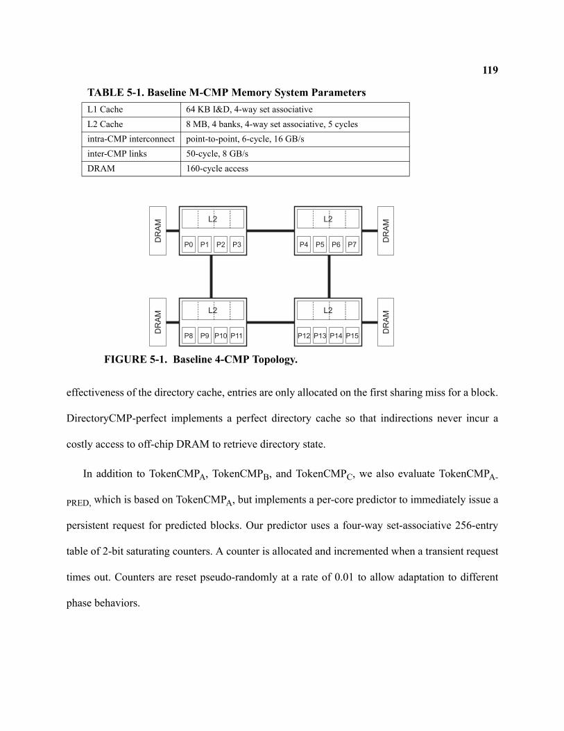
119
effectiveness of the directory cache, entries are only allocated on the first sharing miss for a block.
DirectoryCMP-perfect implements a perfect directory cache so that indirections never incur a
costly access to off-chip DRAM to retrieve directory state.
In addition to TokenCMPA, TokenCMPB, and TokenCMPC, we also evaluate TokenCMPA-
PRED, which is based on TokenCMPA, but implements a per-core predictor to immediately issue a
persistent request for predicted blocks. Our predictor uses a four-way set-associative 256-entry
table of 2-bit saturating counters. A counter is allocated and incremented when a transient request
times out. Counters are reset pseudo-randomly at a rate of 0.01 to allow adaptation to different
phase behaviors.
P0 P1 P2 P3
L2
DR
AM
P4 P5 P6 P7
L2
DR
AM
P8 P9 P10 P11
L2
DR
AM
P12 P13 P14 P15
L2
DR
AM
FIGURE 5-1. Baseline 4-CMP Topology.
TABLE 5-1. Baseline M-CMP Memory System ParametersL1 Cache 64 KB I&D, 4-way set associativeL2 Cache 8 MB, 4 banks, 4-way set associative, 5 cyclesintra-CMP interconnect point-to-point, 6-cycle, 16 GB/sinter-CMP links 50-cycle, 8 GB/sDRAM 160-cycle access
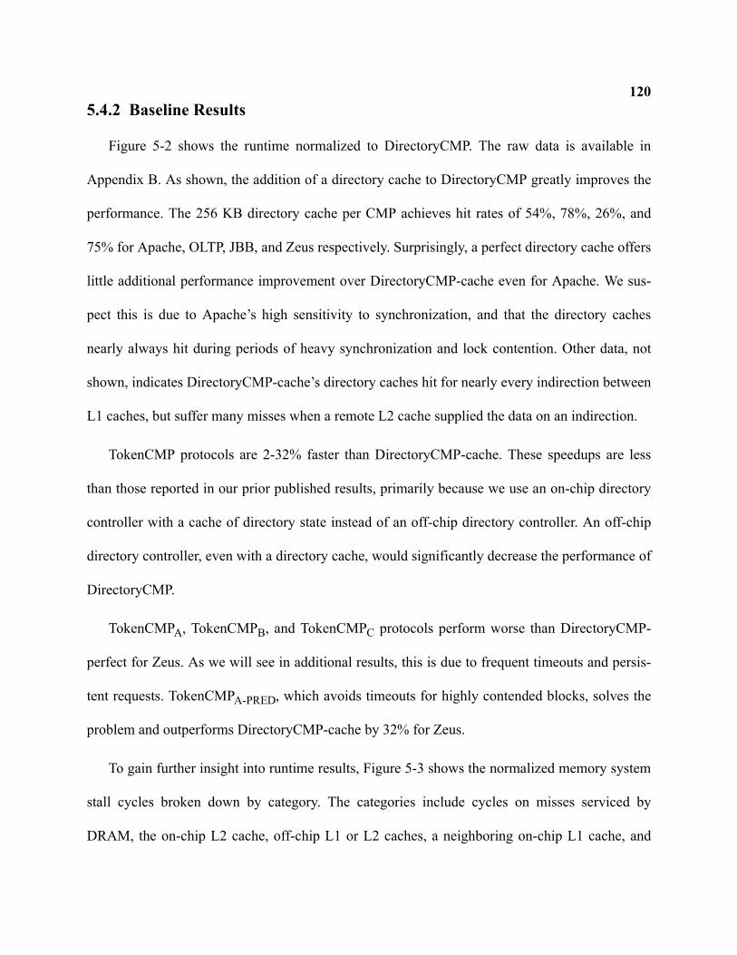
1205.4.2 Baseline Results
Figure 5-2 shows the runtime normalized to DirectoryCMP. The raw data is available in
Appendix B. As shown, the addition of a directory cache to DirectoryCMP greatly improves the
performance. The 256 KB directory cache per CMP achieves hit rates of 54%, 78%, 26%, and
75% for Apache, OLTP, JBB, and Zeus respectively. Surprisingly, a perfect directory cache offers
little additional performance improvement over DirectoryCMP-cache even for Apache. We sus-
pect this is due to Apache’s high sensitivity to synchronization, and that the directory caches
nearly always hit during periods of heavy synchronization and lock contention. Other data, not
shown, indicates DirectoryCMP-cache’s directory caches hit for nearly every indirection between
L1 caches, but suffer many misses when a remote L2 cache supplied the data on an indirection.
TokenCMP protocols are 2-32% faster than DirectoryCMP-cache. These speedups are less
than those reported in our prior published results, primarily because we use an on-chip directory
controller with a cache of directory state instead of an off-chip directory controller. An off-chip
directory controller, even with a directory cache, would significantly decrease the performance of
DirectoryCMP.
TokenCMPA, TokenCMPB, and TokenCMPC protocols perform worse than DirectoryCMP-
perfect for Zeus. As we will see in additional results, this is due to frequent timeouts and persis-
tent requests. TokenCMPA-PRED, which avoids timeouts for highly contended blocks, solves the
problem and outperforms DirectoryCMP-cache by 32% for Zeus.
To gain further insight into runtime results, Figure 5-3 shows the normalized memory system
stall cycles broken down by category. The categories include cycles on misses serviced by
DRAM, the on-chip L2 cache, off-chip L1 or L2 caches, a neighboring on-chip L1 cache, and
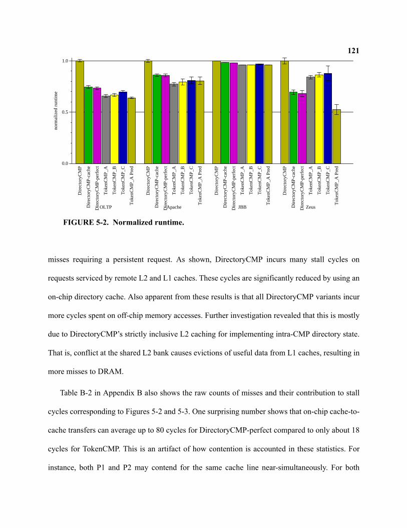
121
misses requiring a persistent request. As shown, DirectoryCMP incurs many stall cycles on
requests serviced by remote L2 and L1 caches. These cycles are significantly reduced by using an
on-chip directory cache. Also apparent from these results is that all DirectoryCMP variants incur
more cycles spent on off-chip memory accesses. Further investigation revealed that this is mostly
due to DirectoryCMP’s strictly inclusive L2 caching for implementing intra-CMP directory state.
That is, conflict at the shared L2 bank causes evictions of useful data from L1 caches, resulting in
more misses to DRAM.
Table B-2 in Appendix B also shows the raw counts of misses and their contribution to stall
cycles corresponding to Figures 5-2 and 5-3. One surprising number shows that on-chip cache-to-
cache transfers can average up to 80 cycles for DirectoryCMP-perfect compared to only about 18
cycles for TokenCMP. This is an artifact of how contention is accounted in these statistics. For
instance, both P1 and P2 may contend for the same cache line near-simultaneously. For both
0.0
0.5
1.0no
rmal
ized
run
time
Dire
ctor
yCM
P
Dire
ctor
yCM
P-c
ache
Dire
ctor
yCM
P-p
erfe
ct
Tok
enC
MP
_A
Tok
enC
MP
_B
Tok
enC
MP
_C
Tok
enC
MP
_A P
red
OLTP
Dire
ctor
yCM
P
Dire
ctor
yCM
P-c
ache
Dire
ctor
yCM
P-p
erfe
ct
Tok
enC
MP
_A
Tok
enC
MP
_B
Tok
enC
MP
_C
Tok
enC
MP
_A P
red
Apache
Dire
ctor
yCM
P
Dire
ctor
yCM
P-c
ache
Dire
ctor
yCM
P-p
erfe
ct
Tok
enC
MP
_A
Tok
enC
MP
_B
Tok
enC
MP
_C
Tok
enC
MP
_A P
red
JBB
Dire
ctor
yCM
P
Dire
ctor
yCM
P-c
ache
Dire
ctor
yCM
P-p
erfe
ct
Tok
enC
MP
_A
Tok
enC
MP
_B
Tok
enC
MP
_C
Tok
enC
MP
_A P
red
Zeus
FIGURE 5-2. Normalized runtime.
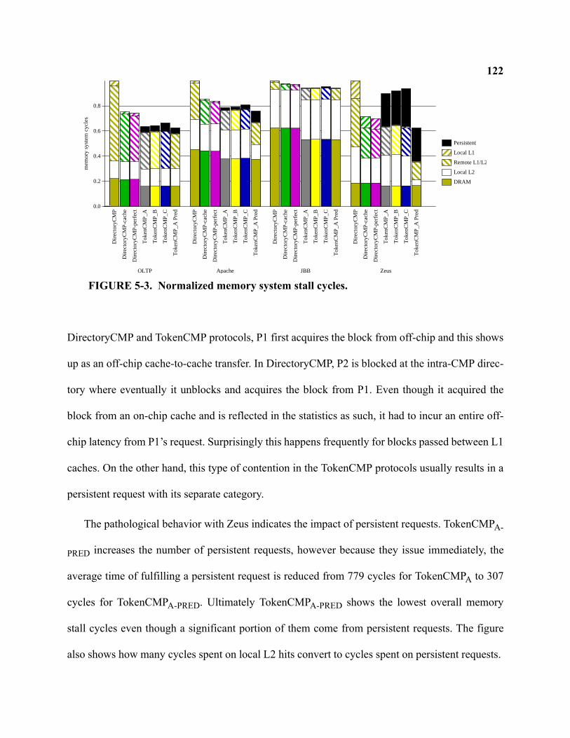
122
DirectoryCMP and TokenCMP protocols, P1 first acquires the block from off-chip and this shows
up as an off-chip cache-to-cache transfer. In DirectoryCMP, P2 is blocked at the intra-CMP direc-
tory where eventually it unblocks and acquires the block from P1. Even though it acquired the
block from an on-chip cache and is reflected in the statistics as such, it had to incur an entire off-
chip latency from P1’s request. Surprisingly this happens frequently for blocks passed between L1
caches. On the other hand, this type of contention in the TokenCMP protocols usually results in a
persistent request with its separate category.
The pathological behavior with Zeus indicates the impact of persistent requests. TokenCMPA-
PRED increases the number of persistent requests, however because they issue immediately, the
average time of fulfilling a persistent request is reduced from 779 cycles for TokenCMPA to 307
cycles for TokenCMPA-PRED. Ultimately TokenCMPA-PRED shows the lowest overall memory
stall cycles even though a significant portion of them come from persistent requests. The figure
also shows how many cycles spent on local L2 hits convert to cycles spent on persistent requests.
0.0
0.2
0.4
0.6
0.8
me
mo
ry s
yste
m c
ycle
s
Persistent
Local L1
Remote L1/L2
Local L2
DRAM
Dire
cto
ryC
MP
Dire
cto
ryC
MP
-ca
che
Dire
cto
ryC
MP
-pe
rfe
ct
To
ken
CM
P_
A
To
ken
CM
P_
B
To
ken
CM
P_
C
To
ken
CM
P_
A P
red
OLTP
Dire
cto
ryC
MP
Dire
cto
ryC
MP
-ca
che
Dire
cto
ryC
MP
-pe
rfe
ct
To
ken
CM
P_
A
To
ken
CM
P_
B
To
ken
CM
P_
C
To
ken
CM
P_
A P
red
ApacheD
ire
cto
ryC
MP
Dire
cto
ryC
MP
-ca
che
Dire
cto
ryC
MP
-pe
rfe
ct
To
ken
CM
P_
A
To
ken
CM
P_
B
To
ken
CM
P_
C
To
ken
CM
P_
A P
red
JBB
Dire
cto
ryC
MP
Dire
cto
ryC
MP
-ca
che
Dire
cto
ryC
MP
-pe
rfe
ct
To
ken
CM
P_
A
To
ken
CM
P_
B
To
ken
CM
P_
C
To
ken
CM
P_
A P
red
Zeus
FIGURE 5-3. Normalized memory system stall cycles.
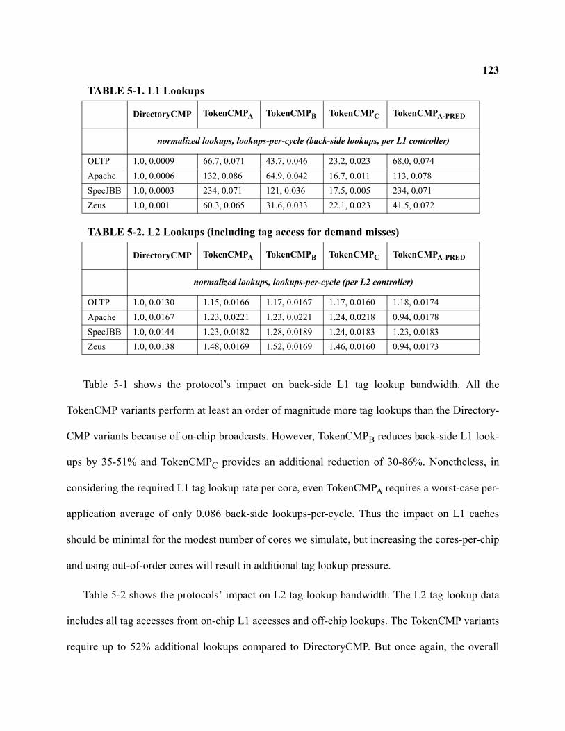
123
Table 5-1 shows the protocol’s impact on back-side L1 tag lookup bandwidth. All the
TokenCMP variants perform at least an order of magnitude more tag lookups than the Directory-
CMP variants because of on-chip broadcasts. However, TokenCMPB reduces back-side L1 look-
ups by 35-51% and TokenCMPC provides an additional reduction of 30-86%. Nonetheless, in
considering the required L1 tag lookup rate per core, even TokenCMPA requires a worst-case per-
application average of only 0.086 back-side lookups-per-cycle. Thus the impact on L1 caches
should be minimal for the modest number of cores we simulate, but increasing the cores-per-chip
and using out-of-order cores will result in additional tag lookup pressure.
Table 5-2 shows the protocols’ impact on L2 tag lookup bandwidth. The L2 tag lookup data
includes all tag accesses from on-chip L1 accesses and off-chip lookups. The TokenCMP variants
require up to 52% additional lookups compared to DirectoryCMP. But once again, the overall
TABLE 5-1. L1 Lookups
DirectoryCMP TokenCMPA TokenCMPB TokenCMPC TokenCMPA-PRED
normalized lookups, lookups-per-cycle (back-side lookups, per L1 controller)
OLTP 1.0, 0.0009 66.7, 0.071 43.7, 0.046 23.2, 0.023 68.0, 0.074Apache 1.0, 0.0006 132, 0.086 64.9, 0.042 16.7, 0.011 113, 0.078SpecJBB 1.0, 0.0003 234, 0.071 121, 0.036 17.5, 0.005 234, 0.071Zeus 1.0, 0.001 60.3, 0.065 31.6, 0.033 22.1, 0.023 41.5, 0.072
TABLE 5-2. L2 Lookups (including tag access for demand misses)
DirectoryCMP TokenCMPA TokenCMPB TokenCMPC TokenCMPA-PRED
normalized lookups, lookups-per-cycle (per L2 controller)
OLTP 1.0, 0.0130 1.15, 0.0166 1.17, 0.0167 1.17, 0.0160 1.18, 0.0174Apache 1.0, 0.0167 1.23, 0.0221 1.23, 0.0221 1.24, 0.0218 0.94, 0.0178SpecJBB 1.0, 0.0144 1.23, 0.0182 1.28, 0.0189 1.24, 0.0183 1.23, 0.0183Zeus 1.0, 0.0138 1.48, 0.0169 1.52, 0.0169 1.46, 0.0160 0.94, 0.0173
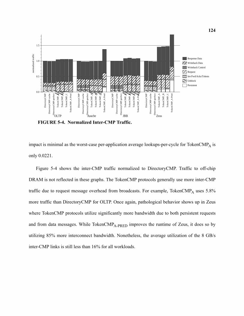
124
impact is minimal as the worst-case per-application average lookups-per-cycle for TokenCMPA is
only 0.0221.
Figure 5-4 shows the inter-CMP traffic normalized to DirectoryCMP. Traffic to off-chip
DRAM is not reflected in these graphs. The TokenCMP protocols generally use more inter-CMP
traffic due to request message overhead from broadcasts. For example, TokenCMPA uses 5.8%
more traffic than DirectoryCMP for OLTP. Once again, pathological behavior shows up in Zeus
where TokenCMP protocols utilize significantly more bandwidth due to both persistent requests
and from data messages. While TokenCMPA-PRED improves the runtime of Zeus, it does so by
utilizing 85% more interconnect bandwidth. Nonetheless, the average utilization of the 8 GB/s
inter-CMP links is still less than 16% for all workloads.
0.0
0.5
1.0
1.5
no
rma
lize
d tra
ffic
Response Data
Writeback Data
Writeback Control
Request
Inv/Fwd/Acks/Tokens
Unblock
Persistent
Dire
cto
ryC
MP
Dire
cto
ryC
MP
-ca
che
Dire
cto
ryC
MP
-pe
rfe
ct
To
ken
CM
P_
A
To
ken
CM
P_
B
To
ken
CM
P_
C
To
ken
CM
P_
A P
red
OLTP
Dire
cto
ryC
MP
Dire
cto
ryC
MP
-ca
che
Dire
cto
ryC
MP
-pe
rfe
ct
To
ken
CM
P_
A
To
ken
CM
P_
B
To
ken
CM
P_
C
To
ken
CM
P_
A P
red
ApacheD
ire
cto
ryC
MP
Dire
cto
ryC
MP
-ca
che
Dire
cto
ryC
MP
-pe
rfe
ct
To
ken
CM
P_
A
To
ken
CM
P_
B
To
ken
CM
P_
C
To
ken
CM
P_
A P
red
JBB
Dire
cto
ryC
MP
Dire
cto
ryC
MP
-ca
che
Dire
cto
ryC
MP
-pe
rfe
ct
To
ken
CM
P_
A
To
ken
CM
P_
B
To
ken
CM
P_
C
To
ken
CM
P_
A P
red
Zeus
FIGURE 5-4. Normalized Inter-CMP Traffic.
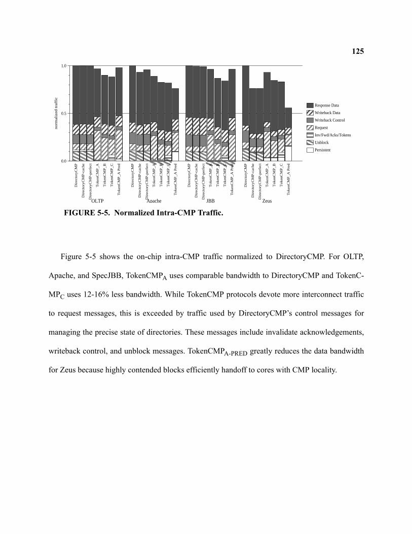
125
Figure 5-5 shows the on-chip intra-CMP traffic normalized to DirectoryCMP. For OLTP,
Apache, and SpecJBB, TokenCMPA uses comparable bandwidth to DirectoryCMP and TokenC-
MPC uses 12-16% less bandwidth. While TokenCMP protocols devote more interconnect traffic
to request messages, this is exceeded by traffic used by DirectoryCMP’s control messages for
managing the precise state of directories. These messages include invalidate acknowledgements,
writeback control, and unblock messages. TokenCMPA-PRED greatly reduces the data bandwidth
for Zeus because highly contended blocks efficiently handoff to cores with CMP locality.
0.0
0.5
1.0
no
rma
lize
d tra
ffic
Response Data
Writeback Data
Writeback Control
Request
Inv/Fwd/Acks/Tokens
Unblock
Persistent
Dire
cto
ryC
MP
Dire
cto
ryC
MP
-ca
che
Dire
cto
ryC
MP
-pe
rfe
ct
To
ken
CM
P_
A
To
ken
CM
P_
B
To
ken
CM
P_
C
To
ken
CM
P_
A P
red
OLTP
Dire
cto
ryC
MP
Dire
cto
ryC
MP
-ca
che
Dire
cto
ryC
MP
-pe
rfe
ct
To
ken
CM
P_
A
To
ken
CM
P_
B
To
ken
CM
P_
C
To
ken
CM
P_
A P
red
Apache
Dire
cto
ryC
MP
Dire
cto
ryC
MP
-ca
che
Dire
cto
ryC
MP
-pe
rfe
ct
To
ken
CM
P_
A
To
ken
CM
P_
B
To
ken
CM
P_
C
To
ken
CM
P_
A P
red
JBB
Dire
cto
ryC
MP
Dire
cto
ryC
MP
-ca
che
Dire
cto
ryC
MP
-pe
rfe
ct
To
ken
CM
P_
A
To
ken
CM
P_
B
To
ken
CM
P_
C
To
ken
CM
P_
A P
red
Zeus
FIGURE 5-5. Normalized Intra-CMP Traffic.
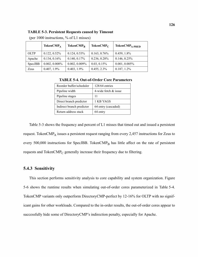
126
Table 5-3 shows the frequency and percent of L1 misses that timed out and issued a persistent
request. TokenCMPA issues a persistent request ranging from every 2,457 instructions for Zeus to
every 500,000 instructions for SpecJBB. TokenCMPB has little affect on the rate of persistent
requests and TokenCMPC generally increase their frequency due to filtering.
5.4.3 Sensitivity
This section performs sensitivity analysis to core capability and system organization. Figure
5-6 shows the runtime results when simulating out-of-order cores parameterized in Table 5-4.
TokenCMP variants only outperform DirectoryCMP-perfect by 12-16% for OLTP with no signif-
icant gains for other workloads. Compared to the in-order results, the out-of-order cores appear to
successfully hide some of DirectoryCMP’s indirection penalty, especially for Apache.
TABLE 5-3. Persistent Requests caused by Timeout (per 1000 instructions, % of L1 misses)
TokenCMPA TokenCMPB TokenCMPC TokenCMPA-PRED
OLTP 0.122, 0.52% 0.124, 0.53% 0.163, 0.76% 0.459, 1.8%Apache 0.134, 0.16% 0.140, 0.17% 0.236, 0.28% 0.146, 0.25%SpecJBB 0.002, 0.008% 0.002, 0.009% 0.03, 0.15% 0.001, 0.005%Zeus 0.407, 1.9% 0.403, 1.9% 0.455, 2.3% 0.187, 1.2%
TABLE 5-4. Out-of-Order Core ParametersReorder buffer/scheduler 128/64 entriesPipeline width 4-wide fetch & issuePipeline stages 11Direct branch predictor 1 KB YAGSIndirect branch predictor 64 entry (cascaded)Return address stack 64 entry
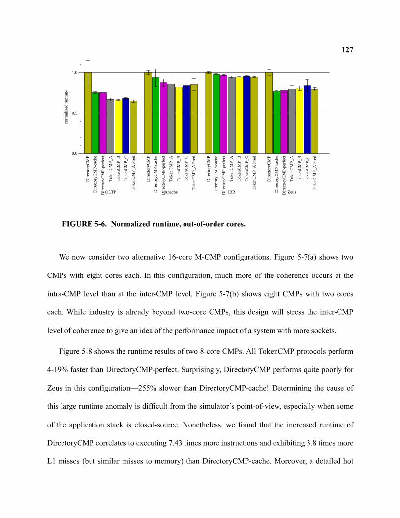
127
We now consider two alternative 16-core M-CMP configurations. Figure 5-7(a) shows two
CMPs with eight cores each. In this configuration, much more of the coherence occurs at the
intra-CMP level than at the inter-CMP level. Figure 5-7(b) shows eight CMPs with two cores
each. While industry is already beyond two-core CMPs, this design will stress the inter-CMP
level of coherence to give an idea of the performance impact of a system with more sockets.
Figure 5-8 shows the runtime results of two 8-core CMPs. All TokenCMP protocols perform
4-19% faster than DirectoryCMP-perfect. Surprisingly, DirectoryCMP performs quite poorly for
Zeus in this configuration—255% slower than DirectoryCMP-cache! Determining the cause of
this large runtime anomaly is difficult from the simulator’s point-of-view, especially when some
of the application stack is closed-source. Nonetheless, we found that the increased runtime of
DirectoryCMP correlates to executing 7.43 times more instructions and exhibiting 3.8 times more
L1 misses (but similar misses to memory) than DirectoryCMP-cache. Moreover, a detailed hot
0.0
0.5
1.0
norm
aliz
ed r
untim
e
Dire
ctor
yCM
P
Dire
ctor
yCM
P-c
ache
Dire
ctor
yCM
P-p
erfe
ct
Tok
enC
MP
_A
Tok
enC
MP
_B
Tok
enC
MP
_C
Tok
enC
MP
_A P
red
OLTP
Dire
ctor
yCM
P
Dire
ctor
yCM
P-c
ache
Dire
ctor
yCM
P-p
erfe
ct
Tok
enC
MP
_A
Tok
enC
MP
_B
Tok
enC
MP
_C
Tok
enC
MP
_A P
red
Apache
Dire
ctor
yCM
P
Dire
ctor
yCM
P-c
ache
Dire
ctor
yCM
P-p
erfe
ct
Tok
enC
MP
_A
Tok
enC
MP
_B
Tok
enC
MP
_C
Tok
enC
MP
_A P
red
JBB
Dire
ctor
yCM
P
Dire
ctor
yCM
P-c
ache
Dire
ctor
yCM
P-p
erfe
ct
Tok
enC
MP
_A
Tok
enC
MP
_B
Tok
enC
MP
_C
Tok
enC
MP
_A P
red
Zeus
FIGURE 5-6. Normalized runtime, out-of-order cores.
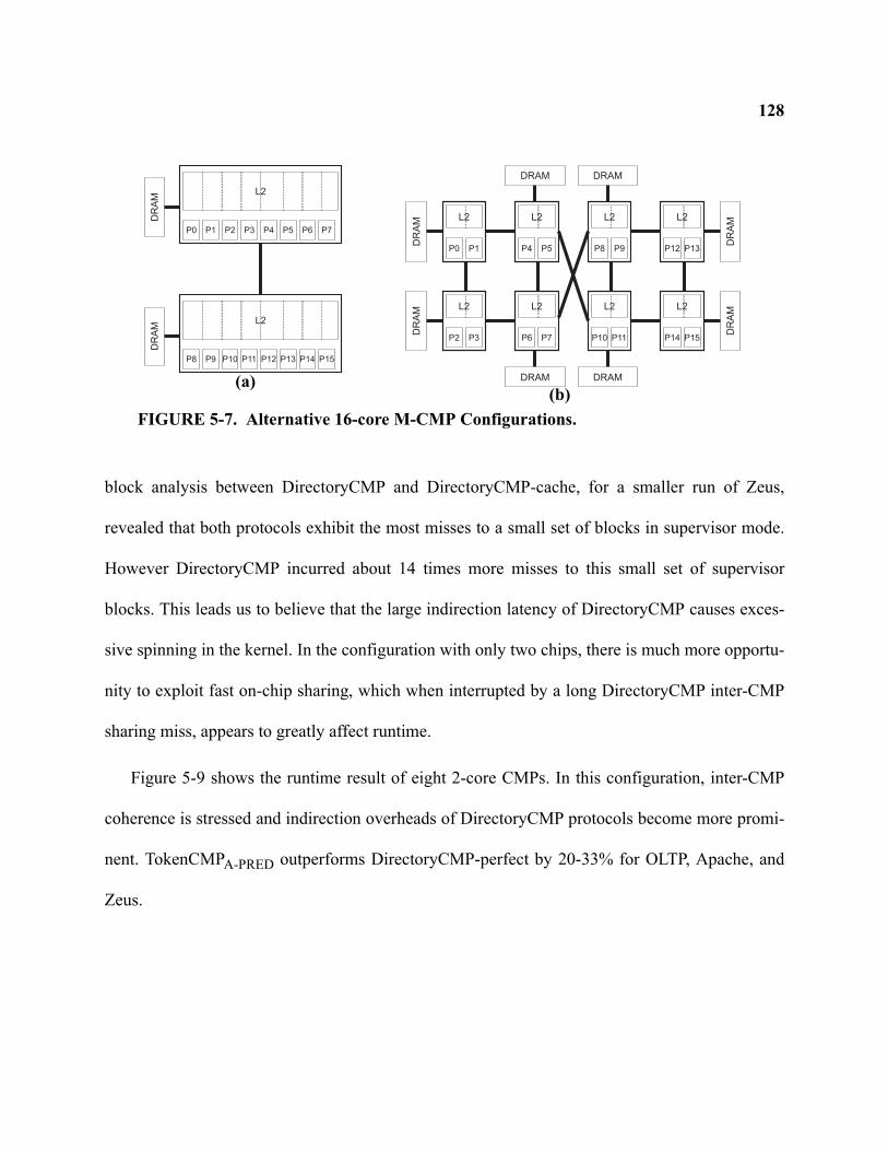
128
block analysis between DirectoryCMP and DirectoryCMP-cache, for a smaller run of Zeus,
revealed that both protocols exhibit the most misses to a small set of blocks in supervisor mode.
However DirectoryCMP incurred about 14 times more misses to this small set of supervisor
blocks. This leads us to believe that the large indirection latency of DirectoryCMP causes exces-
sive spinning in the kernel. In the configuration with only two chips, there is much more opportu-
nity to exploit fast on-chip sharing, which when interrupted by a long DirectoryCMP inter-CMP
sharing miss, appears to greatly affect runtime.
Figure 5-9 shows the runtime result of eight 2-core CMPs. In this configuration, inter-CMP
coherence is stressed and indirection overheads of DirectoryCMP protocols become more promi-
nent. TokenCMPA-PRED outperforms DirectoryCMP-perfect by 20-33% for OLTP, Apache, and
Zeus.
P0 P1 P2 P3
L2
DR
AM
P4 P5 P6 P7
P8 P9 P10 P11
L2
DR
AM
P12 P13 P14 P15
P0 P1
L2
DR
AM
P2 P3
L2
DR
AM
P6 P7
L2
P4 P5
L2
P8 P9
L2
P10 P11
L2
P14 P15
L2
P12 P13
L2
DRAM DRAM
DRAM DRAM
DR
AM
DR
AM
FIGURE 5-7. Alternative 16-core M-CMP Configurations.
(a)(b)
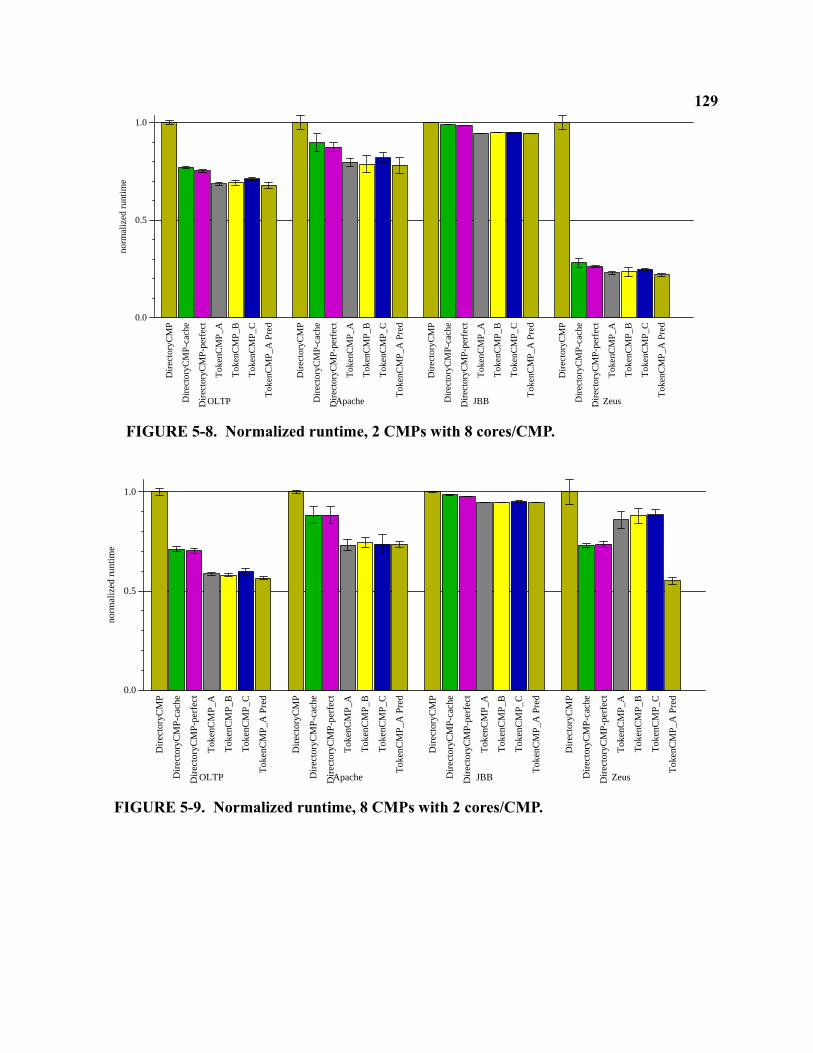
129
0.0
0.5
1.0no
rmal
ized
run
time
Dire
ctor
yCM
P
Dire
ctor
yCM
P-c
ache
Dire
ctor
yCM
P-p
erfe
ct
Tok
enC
MP
_A
Tok
enC
MP
_B
Tok
enC
MP
_C
Tok
enC
MP
_A P
red
OLTP
Dire
ctor
yCM
P
Dire
ctor
yCM
P-c
ache
Dire
ctor
yCM
P-p
erfe
ct
Tok
enC
MP
_A
Tok
enC
MP
_B
Tok
enC
MP
_C
Tok
enC
MP
_A P
red
Apache
Dire
ctor
yCM
P
Dire
ctor
yCM
P-c
ache
Dire
ctor
yCM
P-p
erfe
ct
Tok
enC
MP
_A
Tok
enC
MP
_B
Tok
enC
MP
_C
Tok
enC
MP
_A P
red
JBB
Dire
ctor
yCM
P
Dire
ctor
yCM
P-c
ache
Dire
ctor
yCM
P-p
erfe
ct
Tok
enC
MP
_A
Tok
enC
MP
_B
Tok
enC
MP
_C
Tok
enC
MP
_A P
red
Zeus
FIGURE 5-8. Normalized runtime, 2 CMPs with 8 cores/CMP.
0.0
0.5
1.0
norm
aliz
ed r
untim
e
Dire
ctor
yCM
P
Dire
ctor
yCM
P-c
ache
Dire
ctor
yCM
P-p
erfe
ct
Tok
enC
MP
_A
Tok
enC
MP
_B
Tok
enC
MP
_C
Tok
enC
MP
_A P
red
OLTP
Dire
ctor
yCM
P
Dire
ctor
yCM
P-c
ache
Dire
ctor
yCM
P-p
erfe
ct
Tok
enC
MP
_A
Tok
enC
MP
_B
Tok
enC
MP
_C
Tok
enC
MP
_A P
red
Apache
Dire
ctor
yCM
P
Dire
ctor
yCM
P-c
ache
Dire
ctor
yCM
P-p
erfe
ct
Tok
enC
MP
_A
Tok
enC
MP
_B
Tok
enC
MP
_C
Tok
enC
MP
_A P
red
JBB
Dire
ctor
yCM
P
Dire
ctor
yCM
P-c
ache
Dire
ctor
yCM
P-p
erfe
ct
Tok
enC
MP
_A
Tok
enC
MP
_B
Tok
enC
MP
_C
Tok
enC
MP
_A P
red
Zeus
FIGURE 5-9. Normalized runtime, 8 CMPs with 2 cores/CMP.
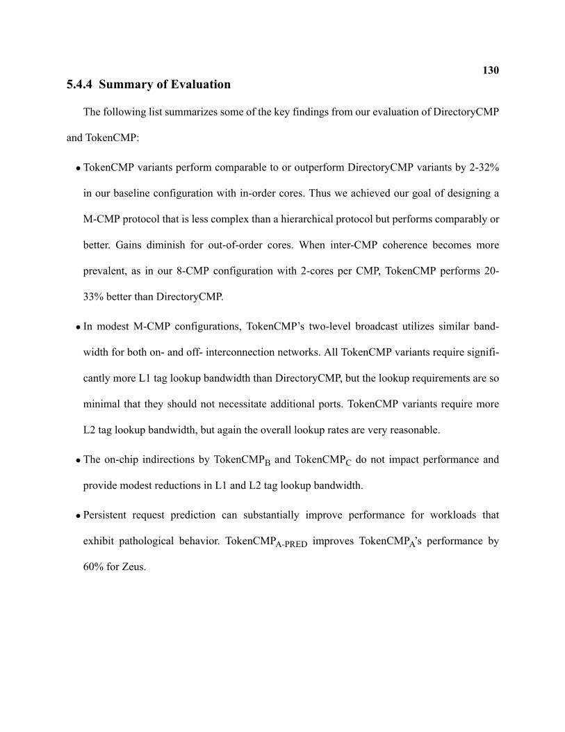
1305.4.4 Summary of Evaluation
The following list summarizes some of the key findings from our evaluation of DirectoryCMP
and TokenCMP:
•TokenCMP variants perform comparable to or outperform DirectoryCMP variants by 2-32%
in our baseline configuration with in-order cores. Thus we achieved our goal of designing a
M-CMP protocol that is less complex than a hierarchical protocol but performs comparably or
better. Gains diminish for out-of-order cores. When inter-CMP coherence becomes more
prevalent, as in our 8-CMP configuration with 2-cores per CMP, TokenCMP performs 20-
33% better than DirectoryCMP.
• In modest M-CMP configurations, TokenCMP’s two-level broadcast utilizes similar band-
width for both on- and off- interconnection networks. All TokenCMP variants require signifi-
cantly more L1 tag lookup bandwidth than DirectoryCMP, but the lookup requirements are so
minimal that they should not necessitate additional ports. TokenCMP variants require more
L2 tag lookup bandwidth, but again the overall lookup rates are very reasonable.
•The on-chip indirections by TokenCMPB and TokenCMPC do not impact performance and
provide modest reductions in L1 and L2 tag lookup bandwidth.
•Persistent request prediction can substantially improve performance for workloads that
exhibit pathological behavior. TokenCMPA-PRED improves TokenCMPA’s performance by
60% for Zeus.
1315.5 Related Work
Many other prior systems have implemented hierarchical coherence. However, most systems
relied on snooping buses as the first level of coherence, greatly simplifying the problem of inter-
facing two protocols.
The Stanford Dash [86] proposed a highly scalable directory-based architecture. Each node in
the directory system was a cluster of processors and contained a portion of the overall memory.
Each cluster used a bus to interconnect the processors and memory, as well as a snooping protocol
for first-level coherence. The SGI Origin2000 [84] system also used bus-based clusters as the
building block for a larger system. The Sequent STiNG [89] combined four processor Intel SMP
nodes into a larger system based on the Scalable Coherence Interconnect (SCI) [53]. The SCI pro-
tocol used a linked list directory protocol.
The Encore Gigamax [13] system proposed a hierarchical system where each level consisted
of a snooping bus. A shared inclusive cache at each level determined when a request traversed to
the next level of the hierarchy.
Scott et al. proposed pruning-cache directories for large-scale multiprocessors [117]. They
focus on reducing the state and message overhead as systems scale. While proposing hierarchies
of directories, they do not address important mechanisms of ordering and race handling like we do
with DirectoryCMP.
The Hierarchical DDM design [55] was a cache-only memory architecture (COMA) system
with a hierarchy of directories and attraction memories. Each level of the hierarchy used a bus
with atomic snooping operations. Another COMA machine was the Kendall Square Research
KSR1 [45]. The KSR1 used a hierarchy of rings. Like the Hierarchical DDM machine, directories
132at the interface between hierarchy levels tracked if a local processor cached the block. Since the
KSR1 used rings instead of atomic buses, handling races and ordering was complicated. Although
the literature does not discuss these details, we suspect that a serial search ordered at each direc-
tory eased complexity.
Prior Multiple-CMP designs include the Compaq Piranha [20] and the IBM Power4/5 systems
[132, 119]. The Compaq Piranha implemented hierarchical directory coherence with an on-chip
crossbar. According to the designers, complexity of the coherence protocol was indeed a serious
problem [19]. The IBM Power4/5 systems implement a logical bus for on-chip coherence and
then interface to a ring-based snooping protocol for coherence between CMPs.
5.6 Discussion and Future Work
This section addresses some shortcomings of TokenCMP and DirectoryCMP that can be
improved with future work.
5.6.1 TokenCMP
The performance policies presented in this chapter target small-scale M-CMP systems. As the
number of cores integrated onto a single chip continue to increase, a performance policy that
avoids excessive broadcasts may be required. TokenCMPC, for example, could be extended with a
new structure that tracks directory state enabling the L2 controller to send requests only to rele-
vant sharers instead of all on-chip caches. The challenge lies in implementing directory state that
does not rely on a precise sequence of state transitions and messages.
Moreover, the TokenCMP performance policies in this chapter do not attempt to provide any
kind of ordering of requests. Racing requests often cause the correctness substrate to use a heavy-
133weight persistent request. If a performance policy can handle some of the common ordering, then
the persistent request mechanism can continue to remain flat as the system scales. Furthermore,
adding order to the system makes performance easier to predict.
On the other hand, if the performance policy invokes persistent requests with enough fre-
quency, then eventually a flat persistent request scheme may impair performance and scalability.
Perhaps persistent request schemes should also be hierarchical. Moreover, using timeouts to
detect possible starvation is often sub-optimal. Some transient requests fail due to local races, but
others fail due to races over slow off-chip links. Ideally a requestor could determine if a race
occurred on-chip or off-chip and adjust the retry timeout accordingly.
Other future work could develop performance policies for a greater variety of cache hierar-
chies, such as L3 caches and D-NUCA structures [73].
5.6.2 DirectoryCMP
The primary drawback of DirectoryCMP is its complexity. Much of the complexity stems
from using a hierarchy of directories. But some deals with operating correctly under completely
unordered interconnects. It appears that next-generation, packet-switched interconnects for CMPs
will use deterministic routing that offers point-to-point ordering. This ordering might simplify
DirectoryCMP by eliminating many potential races.
In developing DirectoryCMP, we also questioned if the finite-state machine model is the best
way to both specify a protocol and its implementation. One interesting avenue of future work
might examine pushdown automaton instead of the finite-state model.
1345.7 Conclusion
Multiple-CMP systems will integrate several CMPs to create larger systems. Cache coherence
is a particular challenge for M-CMPs because protocols must keep caches coherent within a CMP
(intra-CMP coherence) and between CMPs (inter-CMP coherence). In this chapter, we first devel-
oped a detailed hierarchical protocol, DirectoryCMP, that uses directories for both intra- and inter-
CMP coherence. Unlike most prior hierarchical systems, DirectoryCMP has no reliance on the
ordering properties of the on- or off-chip interconnect. However combining the two directory pro-
tocols into a single, globally coherent system is both complex and requires additional structures to
maintain order.
We then developed TokenCMP, which leverages token coherence, to create a system that is
flat for correctness but hierarchical for performance. In the common case, our TokenCMP perfor-
mance policies exploit the hierarchy to improve system performance and to reduce bandwidth.
Yet the performance policies do not need to handle all the potential races that can occur with tra-
ditional hierarchical protocols. TokenCMP instead relies on the correctness substrate for the
uncommon races. TokenCMP’s flat correctness substrate, enabled by token coherence, reduces
complexity by treating the system as flat. In full-system simulation, we showed that TokenCMP
performs comparable to, or can even exceed the performance of DirectoryCMP by up to 32%.
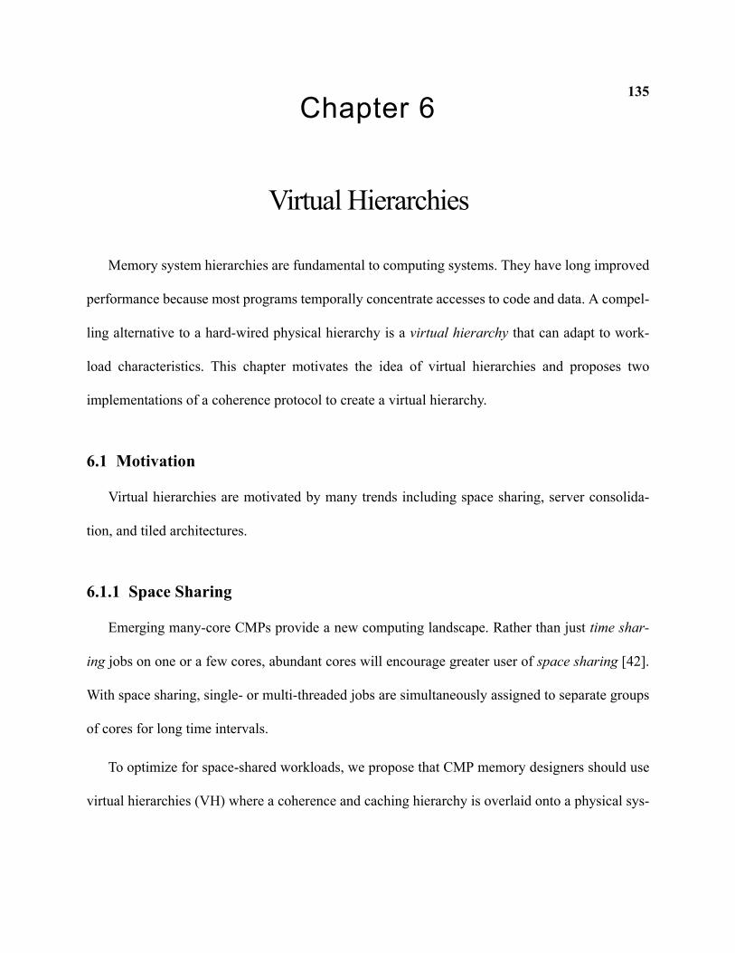
135Chapter 6
Virtual Hierarchies
Memory system hierarchies are fundamental to computing systems. They have long improved
performance because most programs temporally concentrate accesses to code and data. A compel-
ling alternative to a hard-wired physical hierarchy is a virtual hierarchy that can adapt to work-
load characteristics. This chapter motivates the idea of virtual hierarchies and proposes two
implementations of a coherence protocol to create a virtual hierarchy.
6.1 Motivation
Virtual hierarchies are motivated by many trends including space sharing, server consolida-
tion, and tiled architectures.
6.1.1 Space Sharing
Emerging many-core CMPs provide a new computing landscape. Rather than just time shar-
ing jobs on one or a few cores, abundant cores will encourage greater user of space sharing [42].
With space sharing, single- or multi-threaded jobs are simultaneously assigned to separate groups
of cores for long time intervals.
To optimize for space-shared workloads, we propose that CMP memory designers should use
virtual hierarchies (VH) where a coherence and caching hierarchy is overlaid onto a physical sys-
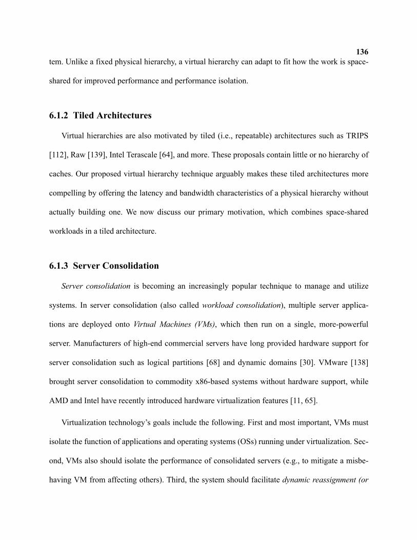
136tem. Unlike a fixed physical hierarchy, a virtual hierarchy can adapt to fit how the work is space-
shared for improved performance and performance isolation.
6.1.2 Tiled Architectures
Virtual hierarchies are also motivated by tiled (i.e., repeatable) architectures such as TRIPS
[112], Raw [139], Intel Terascale [64], and more. These proposals contain little or no hierarchy of
caches. Our proposed virtual hierarchy technique arguably makes these tiled architectures more
compelling by offering the latency and bandwidth characteristics of a physical hierarchy without
actually building one. We now discuss our primary motivation, which combines space-shared
workloads in a tiled architecture.
6.1.3 Server Consolidation
Server consolidation is becoming an increasingly popular technique to manage and utilize
systems. In server consolidation (also called workload consolidation), multiple server applica-
tions are deployed onto Virtual Machines (VMs), which then run on a single, more-powerful
server. Manufacturers of high-end commercial servers have long provided hardware support for
server consolidation such as logical partitions [68] and dynamic domains [30]. VMware [138]
brought server consolidation to commodity x86-based systems without hardware support, while
AMD and Intel have recently introduced hardware virtualization features [11, 65].
Virtualization technology’s goals include the following. First and most important, VMs must
isolate the function of applications and operating systems (OSs) running under virtualization. Sec-
ond, VMs also should isolate the performance of consolidated servers (e.g., to mitigate a misbe-
having VM from affecting others). Third, the system should facilitate dynamic reassignment (or
137
partitioning [120]) of a VM’s resources (e.g., reassigning processor and memory resources to a
VM). Flexible server resource management reduces wasteful over-provisioning and can even
manage heat [64]. Fourth, the system should support inter-VM sharing of memory to enable fea-
tures like content-based page sharing. This scheme, pioneered by Cellular Disco [26] and cur-
rently used by VMware’s ESX server [140], eliminates redundant copies of pages with identical
contents across VMs by mapping them to the same physical frame. Inter-VM page sharing, espe-
cially for code pages, can reduce physical memory demands by up to 60% [140].
Future CMPs with abundant cores provide excellent opportunities to expand server and work-
load consolidation. Figure 6-1 illustrates our baseline 64-tile CMP architecture used in this chap-
ter. Each tile consists of a processor core, private L1 caches, and an L2 bank. Figure 6-2 shows
how future CMPs may run many consolidated workloads with space sharing. That is, different
regions of cores are assigned to different VMs. But memory systems proposed for future CMPs
FIGURE 6-1. Tiled CMP architecture.
FIGURE 6-2. CMP running consolidated servers.
VM 0: database
VM 3: database
VM 1: web server
VM 2: web server
VM 4: middleware
VM 5: middleware
VM 6: middleware
VM 7: middleware
138appear not to target this kind of workload consolidation. Use of global broadcast for all coherence
across such a large number of tiles is not viable. Use of a global directory in DRAM or SRAM
forces many memory accesses to unnecessarily cross the chip, failing to minimize memory access
time or isolate VM performance. Statically distributing the directory among tiles can do much
better, provided that VM monitors (hypervisors) carefully map virtual pages to physical frames
within the VM’s tiles. Requiring the hypervisor to manage cache layout complicates memory allo-
cation, VM reassignment and scheduling, and may limit sharing opportunities.
In this chapter, we propose an implementation of a virtual hierarchy where we overlay a two-
level virtual (or logical) coherence and caching hierarchy on a physically flat CMP that harmo-
nizes with VM assignment. We seek to handle most misses within a VM (intra-VM) with a level-
one coherence protocol that minimizes both miss access time and performance interference with
other VMs. This first-level intra-VM protocol is then augmented by a global level-two inter-VM
coherence protocol that obtains requested data in all cases. The two protocols will operate like a
two-level protocol on a physical hierarchy, but with two key differences. First, the virtual hierar-
chy (VH) is not tied to a physical hierarchy that may or may not match VM assignment. Second,
the VH can dynamically change when VM assignment changes. Before developing our virtual
hierarchy, we first consider existing flat-based approaches to memory systems for the tiled CMP
shown in Figure 6-1.
6.2 Flat Directory-based Coherence
This section discusses some existing flat coherence protocol options for many-core, tiled
CMPs. We assume directory-based coherence because CMPs with 64 or more tiles make frequent
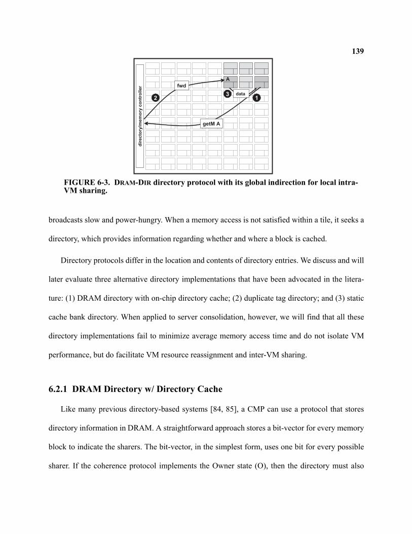
139
broadcasts slow and power-hungry. When a memory access is not satisfied within a tile, it seeks a
directory, which provides information regarding whether and where a block is cached.
Directory protocols differ in the location and contents of directory entries. We discuss and will
later evaluate three alternative directory implementations that have been advocated in the litera-
ture: (1) DRAM directory with on-chip directory cache; (2) duplicate tag directory; and (3) static
cache bank directory. When applied to server consolidation, however, we will find that all these
directory implementations fail to minimize average memory access time and do not isolate VM
performance, but do facilitate VM resource reassignment and inter-VM sharing.
6.2.1 DRAM Directory w/ Directory Cache
Like many previous directory-based systems [84, 85], a CMP can use a protocol that stores
directory information in DRAM. A straightforward approach stores a bit-vector for every memory
block to indicate the sharers. The bit-vector, in the simplest form, uses one bit for every possible
sharer. If the coherence protocol implements the Owner state (O), then the directory must also
dir
ecto
ry/m
em
ory
co
ntr
oller
A
getM A
12
fwd
data3
FIGURE 6-3. DRAM-DIR directory protocol with its global indirection for local intra-VM sharing.
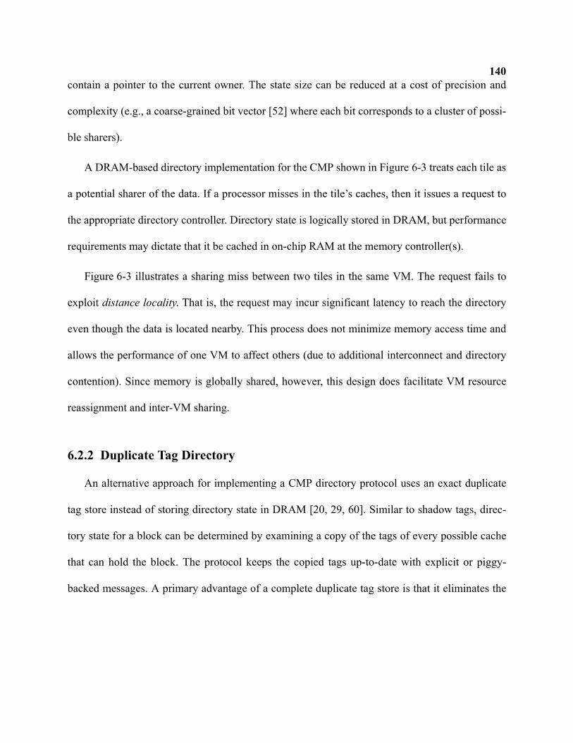
140contain a pointer to the current owner. The state size can be reduced at a cost of precision and
complexity (e.g., a coarse-grained bit vector [52] where each bit corresponds to a cluster of possi-
ble sharers).
A DRAM-based directory implementation for the CMP shown in Figure 6-3 treats each tile as
a potential sharer of the data. If a processor misses in the tile’s caches, then it issues a request to
the appropriate directory controller. Directory state is logically stored in DRAM, but performance
requirements may dictate that it be cached in on-chip RAM at the memory controller(s).
Figure 6-3 illustrates a sharing miss between two tiles in the same VM. The request fails to
exploit distance locality. That is, the request may incur significant latency to reach the directory
even though the data is located nearby. This process does not minimize memory access time and
allows the performance of one VM to affect others (due to additional interconnect and directory
contention). Since memory is globally shared, however, this design does facilitate VM resource
reassignment and inter-VM sharing.
6.2.2 Duplicate Tag Directory
An alternative approach for implementing a CMP directory protocol uses an exact duplicate
tag store instead of storing directory state in DRAM [20, 29, 60]. Similar to shadow tags, direc-
tory state for a block can be determined by examining a copy of the tags of every possible cache
that can hold the block. The protocol keeps the copied tags up-to-date with explicit or piggy-
backed messages. A primary advantage of a complete duplicate tag store is that it eliminates the
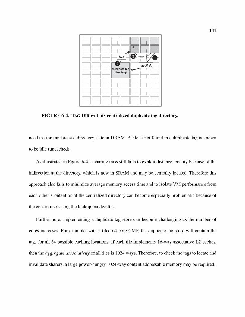
141
need to store and access directory state in DRAM. A block not found in a duplicate tag is known
to be idle (uncached).
As illustrated in Figure 6-4, a sharing miss still fails to exploit distance locality because of the
indirection at the directory, which is now in SRAM and may be centrally located. Therefore this
approach also fails to minimize average memory access time and to isolate VM performance from
each other. Contention at the centralized directory can become especially problematic because of
the cost in increasing the lookup bandwidth.
Furthermore, implementing a duplicate tag store can become challenging as the number of
cores increases. For example, with a tiled 64-core CMP, the duplicate tag store will contain the
tags for all 64 possible caching locations. If each tile implements 16-way associative L2 caches,
then the aggregate associativity of all tiles is 1024 ways. Therefore, to check the tags to locate and
invalidate sharers, a large power-hungry 1024-way content addressable memory may be required.
A
getM A
1fwd data3
duplicate tag
directory
2
FIGURE 6-4. TAG-DIR with its centralized duplicate tag directory.
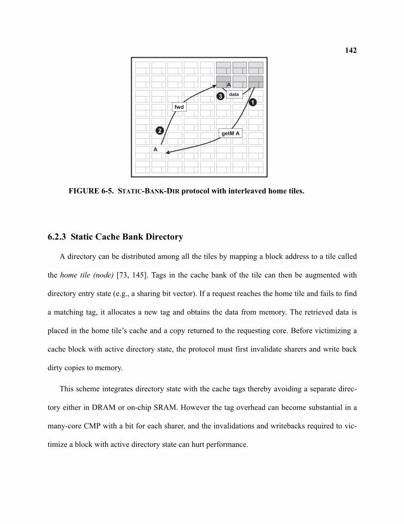
142
6.2.3 Static Cache Bank Directory
A directory can be distributed among all the tiles by mapping a block address to a tile called
the home tile (node) [73, 145]. Tags in the cache bank of the tile can then be augmented with
directory entry state (e.g., a sharing bit vector). If a request reaches the home tile and fails to find
a matching tag, it allocates a new tag and obtains the data from memory. The retrieved data is
placed in the home tile’s cache and a copy returned to the requesting core. Before victimizing a
cache block with active directory state, the protocol must first invalidate sharers and write back
dirty copies to memory.
This scheme integrates directory state with the cache tags thereby avoiding a separate direc-
tory either in DRAM or on-chip SRAM. However the tag overhead can become substantial in a
many-core CMP with a bit for each sharer, and the invalidations and writebacks required to vic-
timize a block with active directory state can hurt performance.
A
getM A
1
2
fwd
data3
A
FIGURE 6-5. STATIC-BANK-DIR protocol with interleaved home tiles.
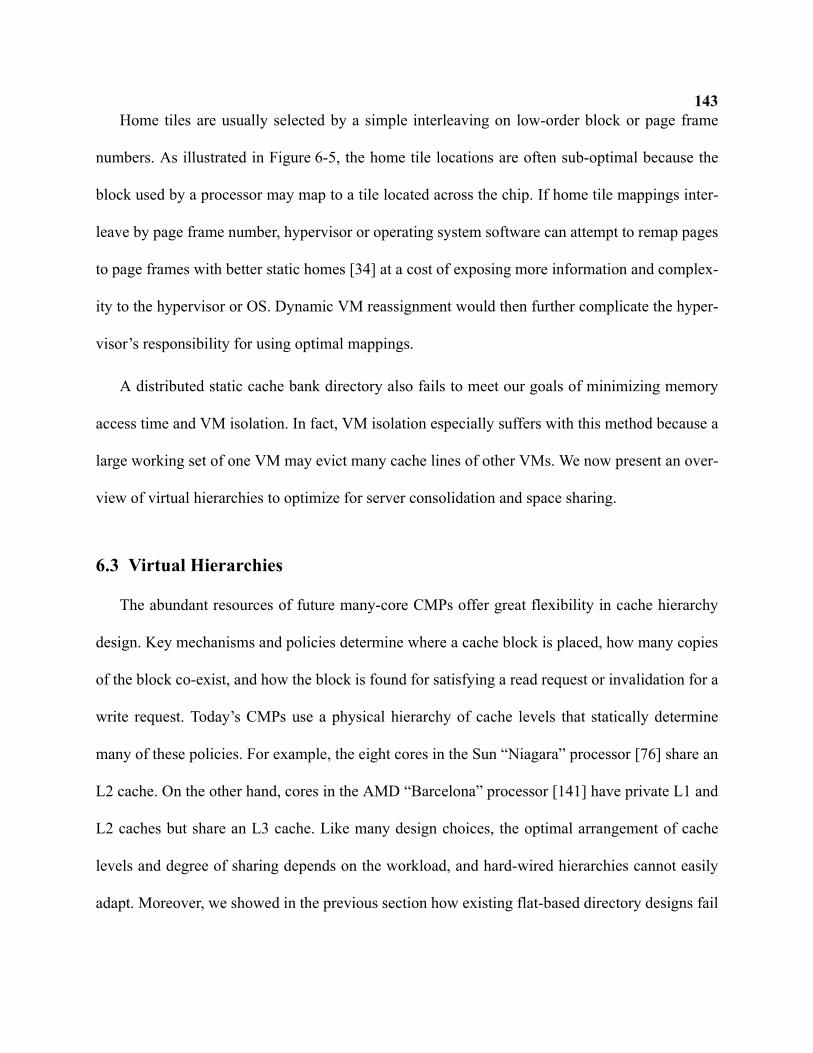
143Home tiles are usually selected by a simple interleaving on low-order block or page frame
numbers. As illustrated in Figure 6-5, the home tile locations are often sub-optimal because the
block used by a processor may map to a tile located across the chip. If home tile mappings inter-
leave by page frame number, hypervisor or operating system software can attempt to remap pages
to page frames with better static homes [34] at a cost of exposing more information and complex-
ity to the hypervisor or OS. Dynamic VM reassignment would then further complicate the hyper-
visor’s responsibility for using optimal mappings.
A distributed static cache bank directory also fails to meet our goals of minimizing memory
access time and VM isolation. In fact, VM isolation especially suffers with this method because a
large working set of one VM may evict many cache lines of other VMs. We now present an over-
view of virtual hierarchies to optimize for server consolidation and space sharing.
6.3 Virtual Hierarchies
The abundant resources of future many-core CMPs offer great flexibility in cache hierarchy
design. Key mechanisms and policies determine where a cache block is placed, how many copies
of the block co-exist, and how the block is found for satisfying a read request or invalidation for a
write request. Today’s CMPs use a physical hierarchy of cache levels that statically determine
many of these policies. For example, the eight cores in the Sun “Niagara” processor [76] share an
L2 cache. On the other hand, cores in the AMD “Barcelona” processor [141] have private L1 and
L2 caches but share an L3 cache. Like many design choices, the optimal arrangement of cache
levels and degree of sharing depends on the workload, and hard-wired hierarchies cannot easily
adapt. Moreover, we showed in the previous section how existing flat-based directory designs fail
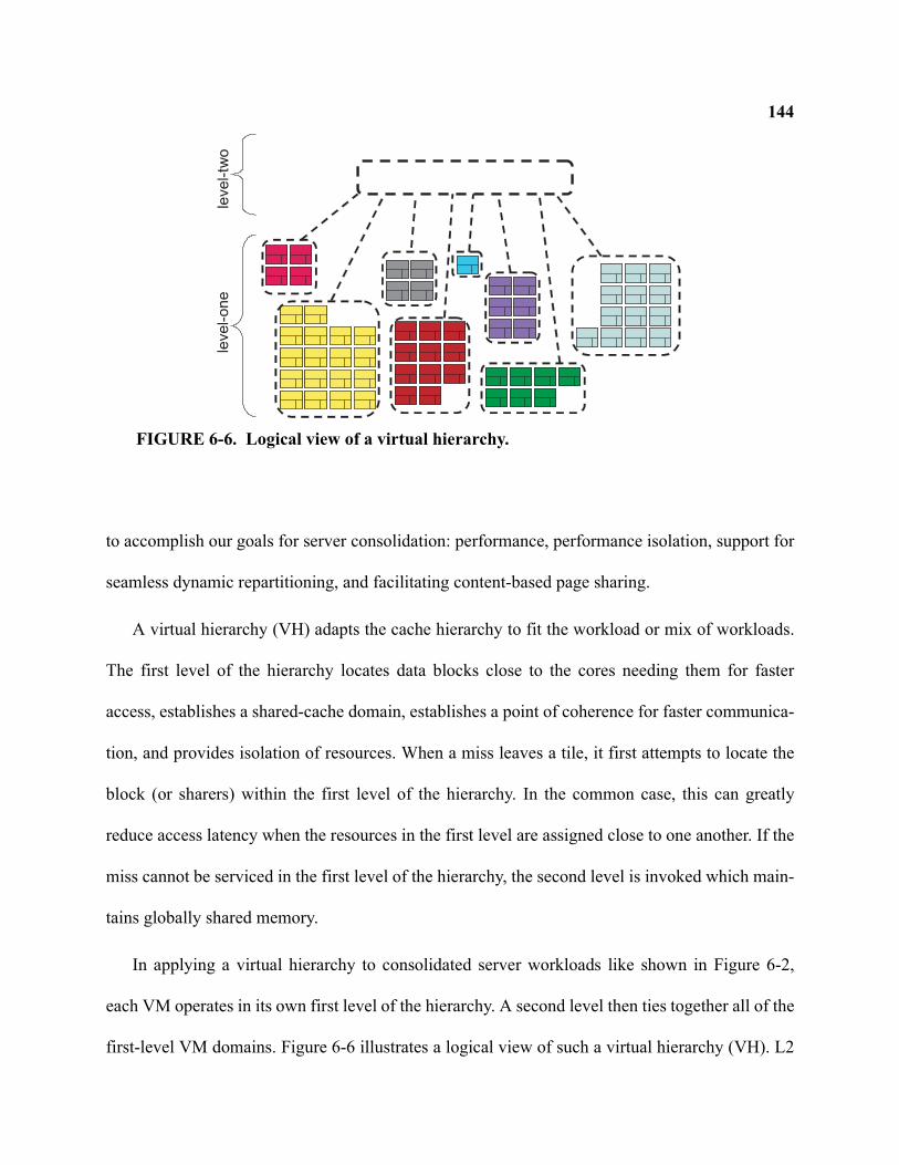
144
to accomplish our goals for server consolidation: performance, performance isolation, support for
seamless dynamic repartitioning, and facilitating content-based page sharing.
A virtual hierarchy (VH) adapts the cache hierarchy to fit the workload or mix of workloads.
The first level of the hierarchy locates data blocks close to the cores needing them for faster
access, establishes a shared-cache domain, establishes a point of coherence for faster communica-
tion, and provides isolation of resources. When a miss leaves a tile, it first attempts to locate the
block (or sharers) within the first level of the hierarchy. In the common case, this can greatly
reduce access latency when the resources in the first level are assigned close to one another. If the
miss cannot be serviced in the first level of the hierarchy, the second level is invoked which main-
tains globally shared memory.
In applying a virtual hierarchy to consolidated server workloads like shown in Figure 6-2,
each VM operates in its own first level of the hierarchy. A second level then ties together all of the
first-level VM domains. Figure 6-6 illustrates a logical view of such a virtual hierarchy (VH). L2
level-
one
level-tw
o
FIGURE 6-6. Logical view of a virtual hierarchy.
145cache capacity is interleaved and shared amongst all cores within the VM. Assuming a hypervisor
schedules threads to cores with space locality as shown, communication within the VM is fast and
localized. Moreover, the shared resources of cache capacity, MSHR registers, interconnect links,
and more are mostly isolated between VMs.
With globally shared memory accomplished via the second-level of coherence, system soft-
ware can seamlessly reschedule resources or migrate virtual machines without expensive software
coherence or the flushing of caches. Content-based sharing between VMs can also reduce the
physical memory demand of workload consolidation [140].
The virtual hierarchy implementations we propose in this chapter are two-level coherence
protocols. The protocols will operate like a two-level protocol on a physical hierarchy, but with
two key differences. First, the virtual hierarchy is not tied to a physical hierarchy that may or may
not match VM assignment. Second, the VH can change dynamically when VM assignment
changes.
The following sub-sections describe our virtual hierarchy protocols. We first start with a level-
one protocol for intra-VM coherence. We then propose alternative global coherence protocols for
completing the virtual hierarchy.
6.3.1 Level-One Intra-VM Directory Protocol
We first develop an intra-VM directory protocol to minimize average memory access time and
interference between VMs. When a memory reference misses in a tile, it is directed to a home tile
which either contains a directory entry (in an L2 tag or separate structure) pertaining to the block
or has no information. The latter case implies the block is not present in this VM. When a block is
146not present or the directory entry contains insufficient coherence permissions (e.g., only a shared
copy when the new request seeks to modify the block), the request is issued to the directory at the
second level. The home tile can also directly service the miss if it holds the data with appropriate
coherence permission.
A surprising challenge for an intra-VM protocol is finding the home tile (that is local to the
VM). For a system with a physical hierarchy, the home tile is usually determined by a simple
interleaving of fixed power-of-two tiles in the local part of the hierarchy. For an intra-VM proto-
col, the home tile is a function of two properties: which tiles belong to a VM, and how many tiles
belong to a VM. Moreover, dynamic VM reassignment can change both. It is also not desirable to
require all VM sizes to be a power-of-two.
To this end, we support dynamic home tiles in VMs of arbitrary sizes using a simple table
lookup that must be performed before a miss leaves a tile (but may be overlapped with L2 cache
access). As illustrated in Figure 6-7, each of the 64 tiles includes a VM Config Table with 64 six-
bit entries indexed by the six least-significant bits of the block number. The figure further shows
table values set to distribute requests approximately evenly among the three home tiles in this VM
(p12, p13, and p14). Tables would be set by a hypervisor (or OS) at VM (or process) reassign-
ment.
Our VM Config Table approach offers a flexible way to create a level of coherence and cach-
ing consisting of any set of tiles. In contrast, the IBM Power4 [132] used a hard-wired address
interleaving for its three L2 cache banks and the Cray T3E [116] translated node identifiers by
adding a base offset to a virtual element identifier to form the physical identifier. Alternatives to
our proposed VM Config Table exist. One alternative extends the page table and TLB structures
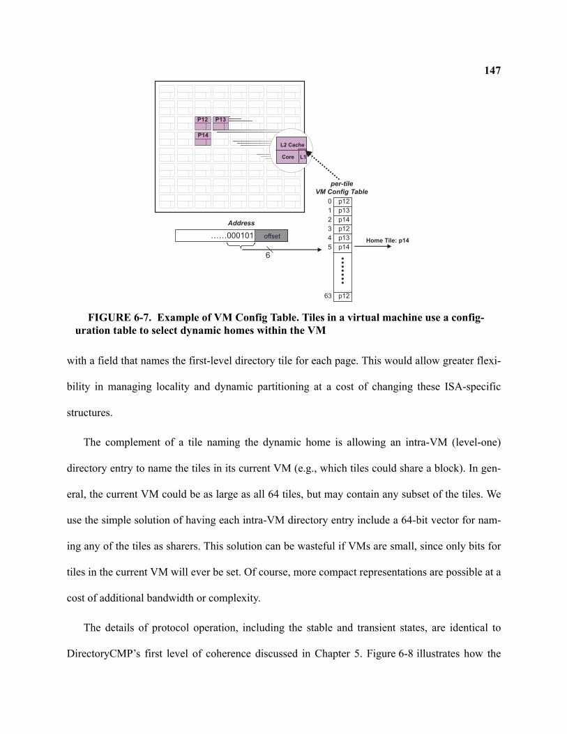
147
with a field that names the first-level directory tile for each page. This would allow greater flexi-
bility in managing locality and dynamic partitioning at a cost of changing these ISA-specific
structures.
The complement of a tile naming the dynamic home is allowing an intra-VM (level-one)
directory entry to name the tiles in its current VM (e.g., which tiles could share a block). In gen-
eral, the current VM could be as large as all 64 tiles, but may contain any subset of the tiles. We
use the simple solution of having each intra-VM directory entry include a 64-bit vector for nam-
ing any of the tiles as sharers. This solution can be wasteful if VMs are small, since only bits for
tiles in the current VM will ever be set. Of course, more compact representations are possible at a
cost of additional bandwidth or complexity.
The details of protocol operation, including the stable and transient states, are identical to
DirectoryCMP’s first level of coherence discussed in Chapter 5. Figure 6-8 illustrates how the
Address
p12
p13
p14
……000101Home Tile: p14
0
1
2
63
offset
per-tile
VM Config Table
6
p12
p12
p13
p14
3
4
5
P12 P13
P14
Core
L2 Cache
L1
FIGURE 6-7. Example of VM Config Table. Tiles in a virtual machine use a config-uration table to select dynamic homes within the VM
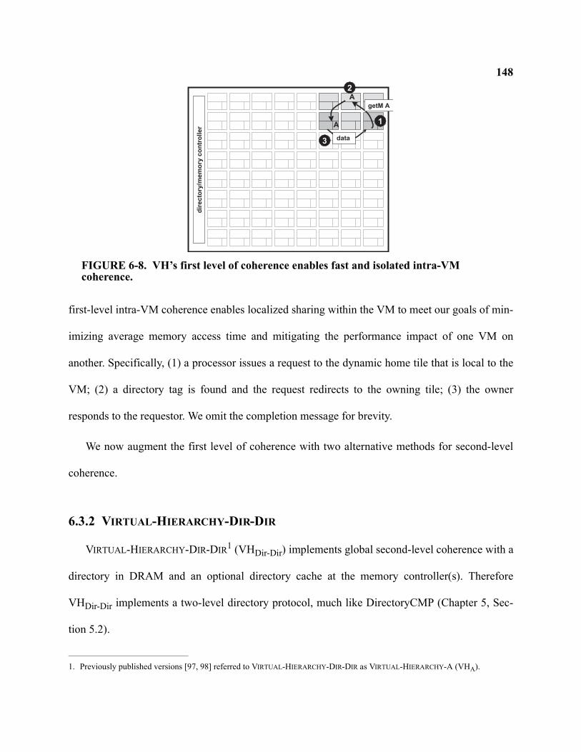
148
first-level intra-VM coherence enables localized sharing within the VM to meet our goals of min-
imizing average memory access time and mitigating the performance impact of one VM on
another. Specifically, (1) a processor issues a request to the dynamic home tile that is local to the
VM; (2) a directory tag is found and the request redirects to the owning tile; (3) the owner
responds to the requestor. We omit the completion message for brevity.
We now augment the first level of coherence with two alternative methods for second-level
coherence.
6.3.2 VIRTUAL-HIERARCHY-DIR-DIR
VIRTUAL-HIERARCHY-DIR-DIR1 (VHDir-Dir) implements global second-level coherence with a
directory in DRAM and an optional directory cache at the memory controller(s). Therefore
VHDir-Dir implements a two-level directory protocol, much like DirectoryCMP (Chapter 5, Sec-
tion 5.2).
1. Previously published versions [97, 98] referred to VIRTUAL-HIERARCHY-DIR-DIR as VIRTUAL-HIERARCHY-A (VHA).
A
getM A
1
2
data
A
dir
ecto
ry/m
em
ory
co
ntr
oller
3
FIGURE 6-8. VH’s first level of coherence enables fast and isolated intra-VM coherence.
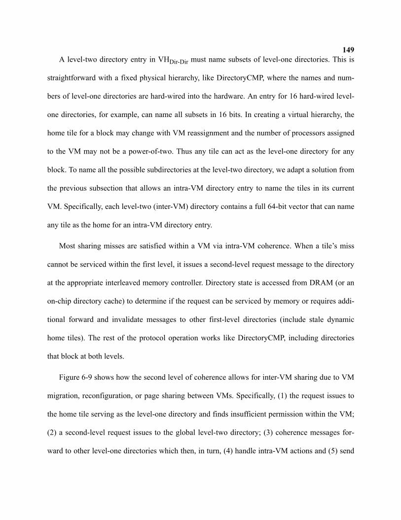
149A level-two directory entry in VHDir-Dir must name subsets of level-one directories. This is
straightforward with a fixed physical hierarchy, like DirectoryCMP, where the names and num-
bers of level-one directories are hard-wired into the hardware. An entry for 16 hard-wired level-
one directories, for example, can name all subsets in 16 bits. In creating a virtual hierarchy, the
home tile for a block may change with VM reassignment and the number of processors assigned
to the VM may not be a power-of-two. Thus any tile can act as the level-one directory for any
block. To name all the possible subdirectories at the level-two directory, we adapt a solution from
the previous subsection that allows an intra-VM directory entry to name the tiles in its current
VM. Specifically, each level-two (inter-VM) directory contains a full 64-bit vector that can name
any tile as the home for an intra-VM directory entry.
Most sharing misses are satisfied within a VM via intra-VM coherence. When a tile’s miss
cannot be serviced within the first level, it issues a second-level request message to the directory
at the appropriate interleaved memory controller. Directory state is accessed from DRAM (or an
on-chip directory cache) to determine if the request can be serviced by memory or requires addi-
tional forward and invalidate messages to other first-level directories (include stale dynamic
home tiles). The rest of the protocol operation works like DirectoryCMP, including directories
that block at both levels.
Figure 6-9 shows how the second level of coherence allows for inter-VM sharing due to VM
migration, reconfiguration, or page sharing between VMs. Specifically, (1) the request issues to
the home tile serving as the level-one directory and finds insufficient permission within the VM;
(2) a second-level request issues to the global level-two directory; (3) coherence messages for-
ward to other level-one directories which then, in turn, (4) handle intra-VM actions and (5) send
150
an Ack or data on behalf of the entire level-one directory; (6) finally the level-one directory fin-
ishes the request on behalf of the requestor (completion messages not shown).
VHDir-Dir resolves races identically to DirectoryCMP as described in Section 5.2.4 of Chapter
5. However because both protocol levels in VHDir-Dir operate on the same interconnection net-
work, VHDir-Dir requires additional virtual networks to prevent deadlock due to insufficient end-
point or interconnect resources. Specifically, separate virtual networks are required for first-level
requests, second-level requests, first-level forwards, second-level forwards, and response mes-
sages.
Hypervisor or system software can change the VM Config Tables at any time without any
other explicit actions. When VM Config Tables change, the dynamic home tile assignment for a
given block may cause a first-level request to reach a first-level sharer instead of a first-level
directory. Although it is tempting to satisfy the request directly, correct protocol operation
requires a second-level request to issue to the global directory to ensure the second-level directory
tracks the new dynamic home tile as a first-level directory.
getM A
1
2
3
A
A
Adir
ecto
ry/m
em
ory
co
ntr
oll
er
getM A
Fwd
Fwd
data
data
data
4
5
6
FIGURE 6-9. VHDir-Dir Example. VHDir-Dir’s second-level coherence (dashed lines)facilitates VM reassignment and content-based page sharing.
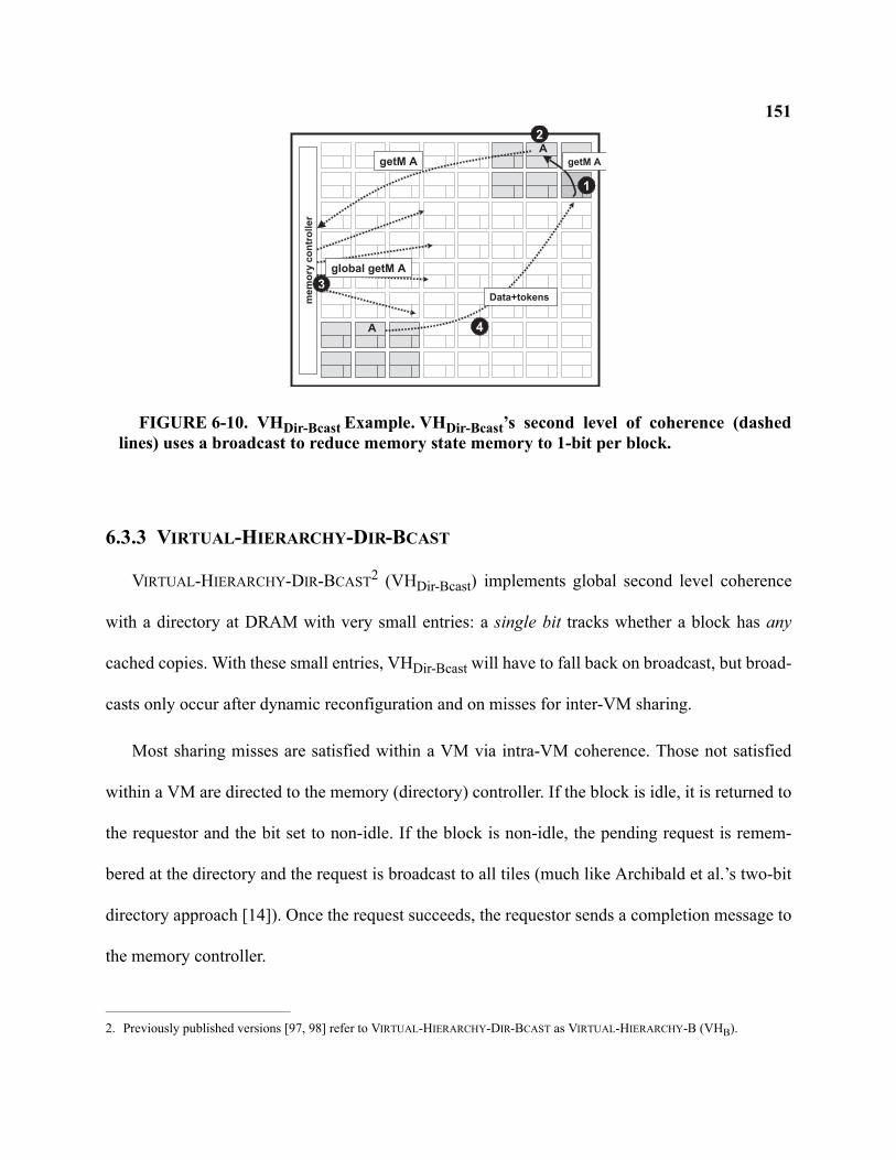
151
6.3.3 VIRTUAL-HIERARCHY-DIR-BCAST
VIRTUAL-HIERARCHY-DIR-BCAST2 (VHDir-Bcast) implements global second level coherence
with a directory at DRAM with very small entries: a single bit tracks whether a block has any
cached copies. With these small entries, VHDir-Bcast will have to fall back on broadcast, but broad-
casts only occur after dynamic reconfiguration and on misses for inter-VM sharing.
Most sharing misses are satisfied within a VM via intra-VM coherence. Those not satisfied
within a VM are directed to the memory (directory) controller. If the block is idle, it is returned to
the requestor and the bit set to non-idle. If the block is non-idle, the pending request is remem-
bered at the directory and the request is broadcast to all tiles (much like Archibald et al.’s two-bit
directory approach [14]). Once the request succeeds, the requestor sends a completion message to
the memory controller.
2. Previously published versions [97, 98] refer to VIRTUAL-HIERARCHY-DIR-BCAST as VIRTUAL-HIERARCHY-B (VHB).
getM A
1
2
3
A
A
mem
ory
co
ntr
oller
global getM A
getM A
Data+tokens
4
FIGURE 6-10. VHDir-Bcast Example. VHDir-Bcast’s second level of coherence (dashedlines) uses a broadcast to reduce memory state memory to 1-bit per block.
152VHDir-Bcast augments cached copies of blocks with a token count to achieve two key advan-
tages. First, tiles without copies of a block do not need to acknowledge requests (one cache
responds in the common case [51]). Second, the single per-block bit in memory can be thought of
as representing either all or none tokens, similar to the token-count bit used by RING-ORDER (Sec-
tion 4.3.1). In the common case of receiving a clean request to unshared data, this token-count bit
allows memory to respond directly to the requestor with data and all tokens.
To resolve races, VHDir-Bcast borrows the strategies used by VHDir-Dir and DirectoryCMP.
Like VHDir-Bcast and DirectoryCMP, requests at both protocol levels cause the directory to block
until receipt of completion messages. Thus an inter-VM request that reaches a blocked inter-VM
directory buffers and waits until unblocked. If the block at memory is non-idle, the inter-VM
directory broadcasts the request to all tiles. Request messages include a bit to distinguish between
first-level and second-level requests. Unlike VHDir-Dir, second-level requests will reach both
level-one directories and level-one sharers. Tiles that are not first-level directories ignore second-
level request messages. Tiles that are first-level directories (determined by the block address and
the status of the VM Config Table) block, and forward requests to first-level sharers much like
VHDir-Dir and DirectoryCMP. Unlike token coherence, VHDir-Bcast does not require persistent
requests to maintain liveness in the system. Movement of tokens at the first level can only occur
when a dynamic home tile is blocked. When a globally broadcasted request finds a blocked first-
level directory, VHDir-Dir’s strategy of handling these second-level requests with safe states
applies to VHDir-Bcast.
A token coalescing approach must be implemented when handling replacement and writeback
operations to enable the token-count bit at memory to logically represent the holding of either all
153or none of the tokens. First-level sharers in VHDir-Bcast use three-phase writebacks just like Direc-
toryCMP and VHDir-Dir to replace tokens to the first-level directory. If the first-level directory
wishes to replace a tag holding current directory state, it must first invalidate (and collect the
tokens) from the sharers it tracks. VHDir-Bcast does not use three-phase writebacks when replacing
to memory. Instead, the dynamic home tile can immediately send tokens to the memory controller
(along with the data if dirty). The common case replaces all tokens to memory with no racing
request to either first- or second-level directories. In this case, the memory controller completes
the replacement by setting the token-count bit and writing dirty data to DRAM. If, however, the
memory controller is blocked on a second-level request, the data and tokens from the writeback
message are bounced to the outstanding requestor. If the memory controller is not blocked on a
request and the writeback message does not contain all the tokens, then the tokens are placed into
a Token Holding Buffer located at each memory controller.
The Token Holding Buffer (THB) temporarily caches the tokens while initiating a FIND
request to locate a first-level directory that can accept and coalesce the tokens. The FIND request
is broadcast to all tiles, and those tiles that have a first-level directory tag allocated respond to the
THB (and do not enter a pending state unlike RING-ORDER’s coalescement process described in
Chapter 4). While a THB entry is allocated, it keeps track of first-level directories that have
responded via a bit-vector. The THB sends the tokens to one of the tiles that responded. If the
tokens are sent to a tile that races and concurrently replaces its own tokens to the memory control-
ler (because a pending state is not used), the received tokens are bounced back to the THB when
the recipient unexpectedly receives them. When the THB receives bounced tokens, if it still does
not hold all tokens for the block, it sends them to another tile that responded to the prior FIND
message sent. This process continues until the THB receives an acknowledgement message from
154a first-level directory indicating that it has accepted the tokens, or the THB has collected all
tokens.
The token coalescent process requires an additional virtual network to prevent deadlock. The
additional network is used for tokens that are bounced back to the memory controller if a tile can-
not accept them (due to a race). FIND messages can use the existing second-level request net-
work. FIND and token responses can use the existing response network.
6.3.4 Virtual Hierarchy Target Assumptions
Our target system assumes a tiled architecture in a 2D mesh interconnect where each tile con-
sists of private write-back L1 caches and an L2 bank. While our virtual hierarchy ideas and imple-
mentations can apply to other target systems, we now discuss some implications of write-through
L1 caches and our assumed 2D mesh interconnect.
Write-through L1 caches are used in the majority today’s mainstream processors. Our VH pro-
tocols can operate in a system where L1 caches write through to the local L2 bank. However if the
dynamic home tile stores directory state in L2 tags (like we assume), then this implies that a cache
block allocates tags in two locations: the local L2 bank of the core writing the block and the L2
bank of the dynamic home tile to store directory state. Allocating a tag in two L2 banks reduces
overall cache capacity. An alternative organization that might better fit write-through L1 caches is
a tile with private L1 caches, a slightly larger private L2 cache, and an L3 bank. In this system, the
VH protocols work the same way except that the dynamic home tile stores directory state in an L3
cache tag and cores always write through to their private L2 cache.
155The assumed 2D mesh interconnect matches well with a virtual hierarchy in our tiled architec-
ture because communication within a VM can be somewhat isolated. Of course adjacent VMs
may share some links (unless a routing strategy avoids this) and traffic from memory will pass
through tiles of other VMs (but memory traffic can travel on virtual channels with other priority
mechanisms). Future multicore chips may use interconnection networks other than a 2D mesh,
and they may not realize the same locality or isolation benefits in a virtual hierarchy.
6.3.5 Virtual Hierarchy Data Placement Optimization
This section describes an optional optimization to the virtual hierarchy protocols that can
improve performance.
As described in the previous sections, both VHDir-Dir and VHDir-Bcast allocate a cache tag at
the dynamic home tile to hold data for satisfying future shared read accesses and directory state in
the tag to identify sharers for invalidation on a write request. To maximize the overall cache
capacity for each workload, the dynamic home tile holds the only L2 copy of the block. That is,
the writeback L1 caches replace a block to the dynamic home tile. Additional policies can option-
ally replicate data in the local L2 slice to improve performance by servicing more misses out of
the local L2 bank rather than the home tile [145, 22, 29].
One optimization we consider is the placement of data based on the sharing status of a block.
For data that is private and unshared, ideally the data is cached in the local L2 slice of the proces-
sor without also consuming an L2 cache tag at the dynamic home tile. Upon an L1 miss (or
access), the local L2 slice can then be checked before issuing a request to the dynamic home tile.
In doing so, we improve the L2 hit latency for private data without wasting an additional L2 tag.
156Implementing this private data optimization requires two key mechanisms. First, there must
be a way in hardware to distinguish private data from shared data. Second, the system must allow
private data to transition to shared upon the first sharing miss. Given the second mechanism, we
can initially treat all misses served by memory as private data. We track this status by adding a
private bit to each cache tag. Upon completing a miss from memory for data initially considered
private, the controller unblocks the dynamic home tile with a special status bit to indicate that it
should not allocate a cache tag for directory state. We then require the global coherence mecha-
nism to locate the private data on the first sharing miss, clear the private bit, and allocate a tag at
the dynamic home tile to service future sharing misses at the first level.
To locate private data with global second-level coherence in VHDir-Dir, the global directory
must point to the tile caching the private data instead of the dynamic home tile. Thus when
unblocking the directories after receiving the private data from memory, the first-level directory
unblocks the second-level directory, but does so with the ID of the unblocker replaced with the ID
of the private requestor. The second-level directory then updates the sharers list appropriately.
To locate private data with global coherence in VHDir-Bcast, we exploit the global broadcast.
When a tile snoops a global request and matches a valid cache tag with the private bit set (and all
tokens), it responds directly to the request. The shared requestor then unblocks the dynamic home
tile which allocates a cache tag. Fortunately since subsequent shared requests for private data
must use the second-level coherence ordered at the memory controllers, race handling is not com-
plicated. The evaluation in Section 6.4 evaluates the private data optimization described in this
section for VHDir-Bcast.
1576.3.6 Virtual-Hierarchy-Dir-NULL
Designers might consider using VH’s first-level of coherence without a backing second-level
coherence protocol. This option—VHDir-NULL—could still accomplish many of our goals for
server consolidation with sufficient hypervisor support. Nonetheless, we see many reasons why
VH’s two coherence levels may be preferred.
VHDir-NULL impacts dynamic VM reassignment as each reconfiguration or rescheduling of
VM resources requires the hypervisor to take complex, time-consuming steps. First, the hypervi-
sor must stop all threads running in the effected VMs. Then it must flush the caches of all tiles
assigned to the effected VMs. Then it updates all VM Config Tables of the effected tiles before it
can finally start scheduling threads. True VH protocols, on the other hand, avoid all of these steps
because the second level of coherence will dynamically migrate blocks to their new home on
demand. Moreover, VM Config Tables in true VH protocols can lazily update during the reconfig-
uration phase because second-level coherence can handle stale dynamic home tile assignments. In
other words, the VM Config Tables in true VH protocols serve only as performance hints whereas
VHDir-NULL must treat them as architected state.
VHDir-NULL impacts the ability to support content-based page sharing between VMs. While
content-based page sharing is typically used for read-only data, and read-only data does not
require cache coherence, the mechanisms for implementing the detection of shared pages is com-
plicated without global cache coherence. In the VMWare ESX implementation, a global hash
table stores hashes of pages to detect identical pages. The hypervisor scans pages in the back-
ground and updates the global hash table. If the table indicates a matching hash value with a dif-
ferent page, a full byte-by-byte comparison ensures a true match. Consider this operation in
158VHDir-NULL: first, the hypervisor must scan pages that are potentially modified in cache (even
read-only pages must be written at some point). To scan a page in VM #1, the hypervisor must run
in a thread with the VM Config Table set to access VM #1’s interleaved caches. However the
hypervisor must also update the global hash table which may have been last modified by a hyper-
visor running on a thread in any processor. Even if VHDir-NULL can implement read-only content-
based page sharing, a VM obtains the data from off-chip DRAM. VHDir-Dir and VHDir-Bcast
improve the latency and reduces off-chip bandwidth demands of these misses by often finding the
data on-chip.
Third, VHDir-NULL precludes optimized workload consolidation at the OS/process level
unless the OS is rewritten to operate without global, transparent cache coherence. VHDir-Dir and
VHDir-Bcast provide the cache coherence to support virtual hierarchies for individual OS pro-
cesses.
Finally, a second level of coherence allows subtle optimizations at the first-level that are not
easily done with VHDir-NULL, such as the optimization of not allocating first-level directory
entries for unshared data (discussed in Section 6.3.5).
6.4 Evaluation Methodology
This section evaluates the virtual hierarchy protocols, VHDir-Dir and VHDir-Bcast, with full-
system simulation.
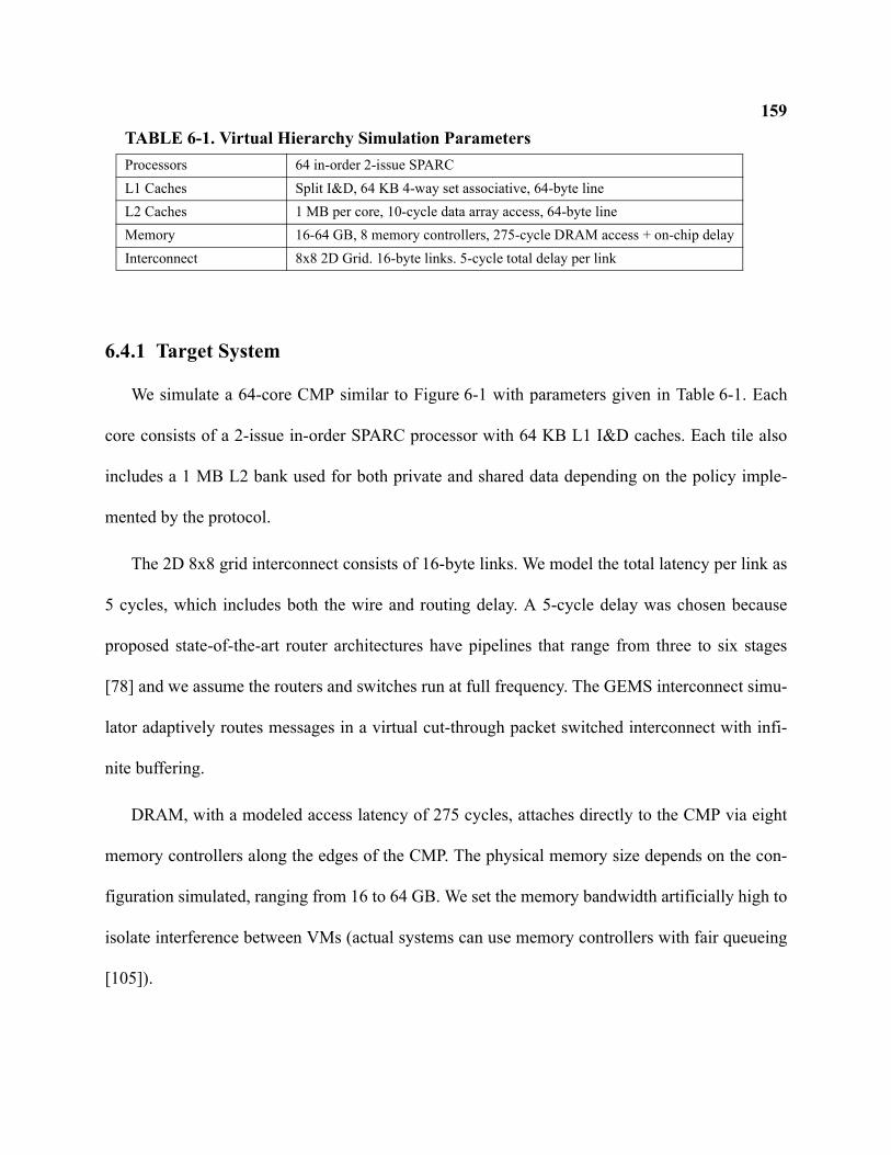
159
6.4.1 Target System
We simulate a 64-core CMP similar to Figure 6-1 with parameters given in Table 6-1. Each
core consists of a 2-issue in-order SPARC processor with 64 KB L1 I&D caches. Each tile also
includes a 1 MB L2 bank used for both private and shared data depending on the policy imple-
mented by the protocol.
The 2D 8x8 grid interconnect consists of 16-byte links. We model the total latency per link as
5 cycles, which includes both the wire and routing delay. A 5-cycle delay was chosen because
proposed state-of-the-art router architectures have pipelines that range from three to six stages
[78] and we assume the routers and switches run at full frequency. The GEMS interconnect simu-
lator adaptively routes messages in a virtual cut-through packet switched interconnect with infi-
nite buffering.
DRAM, with a modeled access latency of 275 cycles, attaches directly to the CMP via eight
memory controllers along the edges of the CMP. The physical memory size depends on the con-
figuration simulated, ranging from 16 to 64 GB. We set the memory bandwidth artificially high to
isolate interference between VMs (actual systems can use memory controllers with fair queueing
[105]).
TABLE 6-1. Virtual Hierarchy Simulation ParametersProcessors 64 in-order 2-issue SPARCL1 Caches Split I&D, 64 KB 4-way set associative, 64-byte lineL2 Caches 1 MB per core, 10-cycle data array access, 64-byte lineMemory 16-64 GB, 8 memory controllers, 275-cycle DRAM access + on-chip delayInterconnect 8x8 2D Grid. 16-byte links. 5-cycle total delay per link
1606.4.2 Approximating Virtualization
Beyond setting up and simulating the commercial workloads described in Chapter 3, a full-
system of virtual machines and consolidated workloads presents additional difficulties. First, our
scheme relies on some hypervisor functionality to set the VM Config Tables on scheduling and
assignment. The development of a full-fledged hypervisor would entail significant development
effort especially since, as of 2007, the only existing SPARC-based hypervisor is written in assem-
bly language [127]. Second, creating workload checkpoints under a hypervisor environment is
further complicated. In simulating multiple different configurations of server consolidation, the
time required to create initial checkpoints of warmed configurations would be significant and
impact the number of configurations we could feasibly simulate.
Our methodology instead evaluates consolidated workloads without simulating the execution
of a hypervisor and without going through the entire process of bringing up each different config-
uration of workload consolidation. Instead, our strategy approximates a virtualized environment
by concurrently simulating multiple functionally-independent machine instances. In this way, we
leverage existing Simics checkpoints to simulate workload consolidation in many different con-
figurations. To do so, we use a script that inputs multiple Simics checkpoint files and outputs a
single checkpoint file that can be loaded by Simics. The script duplicates and renames every spec-
ified device in the system—PCI interfaces, disk drives, memory modules, processors, and more.
Thus the output checkpoint file contains a set of hardware instances for each individual multipro-
cessor workload simulated, including memory.
Once simulating multiple functionally-independent machine instances, we then realistically
map and interleave the processors and memory accesses onto our CMP memory system timing
161model (Ruby). Each workload instance has its own physical address space that completely over-
laps with other workload instances. Therefore, upon receiving a memory request from Simics, the
first task Ruby performs is constructing a new physical address by concatenating the processor
number to the most significant bits of the address. For example, if simulating sixteen workload
instances, the original 32-bit address becomes a 36-bit physical address within Ruby. Memory
controllers interleave on the low-order bits of the block address such that all workloads share an
equal portion of memory at each controller. Although we target a system that supports inter-VM
content-based page sharing, we do not currently simulate this feature.
6.4.3 Scheduling
Although virtual hierarchies optimize for space-sharing, they can still support rich scheduling
and reassignment policies. However we only simulate a statically scheduled assignment of
resources to workloads with no changes throughout our simulation runs. Furthermore, each work-
load maps onto adjacent tiles to maximize the space-sharing opportunities of our protocols.
6.4.4 Workloads
The workloads we consolidate are those described in Chapter 3: OLTP, Apache, Zeus, and
SpecJBB. We first consider configurations that consolidate multiple instances of the same type of
workload into virtual machines of the same size. These homogenous configurations allow us to
report overall runtime after completing some number of transactions because all units of work are
equivalent (i.e., all VMs complete the same type of transaction). Doing so also greatly reduces the
simulation resources required because Virtutech Simics is able to use the same checkpoint images

162
and thereby reduce resident memory usage. To avoid lockstep simulation across all VMs, we stag-
ger the state of each VM by one million cycles before collecting simulation results.
We then simulate server consolidation configurations of different workloads and of different
virtual machine sizes. For these mixed configurations, we run the simulator for 100,000,000
cycles and then count the number of transactions completed for each virtual machine. The cycles-
per-transaction (CPT) for each VM is reported.
Table 6-2 shows the different configurations of server consolidation we simulate.
6.4.5 Protocols
We now discuss the implementation details of the simulated protocols. All implementations
use write-back, write-allocate L1 caching with the local L2 bank non-inclusive.
TABLE 6-2. Server Consolidation Configurations
Configuration Description
OLTP 16x4p Sixteen 4-processor OLTP VMsApache 16x4p Sixteen 4-processor Apache VMsZeus16x4p Sixteen 4-processor Zeus VMsJBB 16x4p Sixteen 4-processor SpecJBB VMsOLTP 8x8p Eight 8-processor OLTP VMsApache 8x8p Eight 8-processor Apache VMsZeus 8x8p Eight 8-processor Zeus VMsJBB 8x8p Eight 8-processor SpecJBB VMsOLTP 4x16p Four 16-processor OLTP VMsApache 4x16p Four 16-processor Apache VMsZeus 4x16p Four 16-processor Zeus VMsJBB 4x16p Four 16-processor SpecJBB VMs
mixed1Two 8-processor Apache VMs, two 16-processor OLTP VMs,
one 8-processor JBB VM, and two 4-processor JBB VMsmixed2 Four 8-processor OLTP VMs, four 8-processor Apache VMs
163DRAM-DIR implements the protocol described in Section 6.2.1 (DRAM Directory). To reduce
the number of copies of a shared block (the level of replication), DRAM-DIR implements a policy
that uses a simple heuristic based on the coherence state of the block. In our MOESI implementa-
tion, an L1 victim in state M, O, or E will always allocate in the local L2 bank. However a block
in the S-state will not allocate in the local bank because it is likely that another tile holds the cor-
responding O-block. If the O-block replaces to the directory, then the subsequent requestor will
become the new owner. The E-state in this protocol sends a non-data control message to the direc-
tory upon replacement to eliminate a potential race. Both protocols implement a one megabyte
directory cache at each memory controller totaling a generous 8 MB of on-chip capacity.
TAG-DIR implements the protocol described in Section 6.2.2 (Duplicate Tag Directory) with
full MOESI states. A centralized tag store, consisting of copied tags from every tile’s caches,
checks all tags on any request. We charge a total of three cycles to access the 1024-way CAM (for
copied L2 tags) and to generate forward or invalidate messages. Like DRAM-DIR, we control the
level of replication with the same heuristic based on the coherence state. To ensure that the dupli-
cate tags are kept up-to-date, tiles send explicit control messages to the tag store when replacing
clean data.
STATIC-BANK-DIR implements the protocol described in Section 6.2.3 (Static Cache Bank
Directory) with MESI states (the home tile is the implicit Owner). Home tiles interleave by the
lowest six bits of the page frame address, and we ensure page frames across workloads map to dif-
ferent tiles by swizzling bits from the artificially constructed memory address. Each L2 tag con-
tains a 64-bit vector to name tiles sharing the block. The L2 controllers handle both indirections
and fetches from memory. L1 caches always replace to the home tile and clean copies silently
164replace. We also explore the impact of interleaving home tiles by block address rather than page
frame address.
VHDir-Dir implements the two-level directory protocol as described in Section 6.3.2 with
MOESI states at both levels. To help manage complexity, the L2 controller treats incoming L1
requests the same regardless of whether the request is from the local L1 or another L1 within the
VM domain. Therefore L1 victims always get replaced to the dynamic home tile. Since our simu-
lations use static scheduling without page sharing and with no rescheduling of resources, second-
level coherence is not invoked. However VHDir-Dir is based on the implementation of Directory-
CMP of Chapter 5 which frequently exercised both levels of coherence.
VHDir-Bcast-Opt implements the protocol as described in Section 6.3.3 with additional optimi-
zations. The most important is the optimization for private data described in Section 6.3.5. We
also allow the dynamic home tile to victimize an L2 block without invalidating any L1 sharers
since VHDir-Bcast-Opt uses a broadcast at the second level. The last optimization we implement is
that memory responses go directly to the requesting tile instead of passing through the first-level
directory. This modestly reduces memory latency by eliminating additional on-chip wire delay.
We do not evaluate VHDir-Bcast (no optimizations) because performance would be identical to
VHDir-Dir given our static workload scheduling that only exercises the first level of coherence.
Note that VHDir-Dir could have also implemented the same optimizations given additional engi-
neering.
An important consideration for CMP memory systems is the number of replicas of a cache
block allowed to coexist [145, 33, 29, 22]. We consider the replication policy an independent
issue that can be layered on top of our proposed mechanisms. Our baseline protocols attempt to
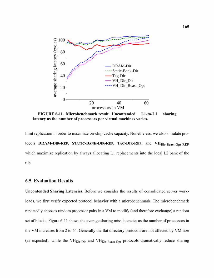
165
limit replication in order to maximize on-chip cache capacity. Nonetheless, we also simulate pro-
tocols DRAM-DIR-REP, STATIC-BANK-DIR-REP, TAG-DIR-REP, and VHDir-Bcast-Opt-REP
which maximize replication by always allocating L1 replacements into the local L2 bank of the
tile.
6.5 Evaluation Results
Uncontended Sharing Latencies. Before we consider the results of consolidated server work-
loads, we first verify expected protocol behavior with a microbenchmark. The microbenchmark
repeatedly chooses random processor pairs in a VM to modify (and therefore exchange) a random
set of blocks. Figure 6-11 shows the average sharing miss latencies as the number of processors in
the VM increases from 2 to 64. Generally the flat directory protocols are not affected by VM size
(as expected), while the VHDir-Dir and VHDir-Bcast-Opt protocols dramatically reduce sharing
20 40 60processors in VM
0
20
40
60
80
100
aver
age
shar
ing
late
ncy
(cyc
les)
DRAM-DirStatic-Bank-DirTag-DirVH_Dir_DirVH_Dir_Bcast_Opt
FIGURE 6-11. Microbenchmark result. Uncontended L1-to-L1 sharinglatency as the number of processors per virtual machines varies.
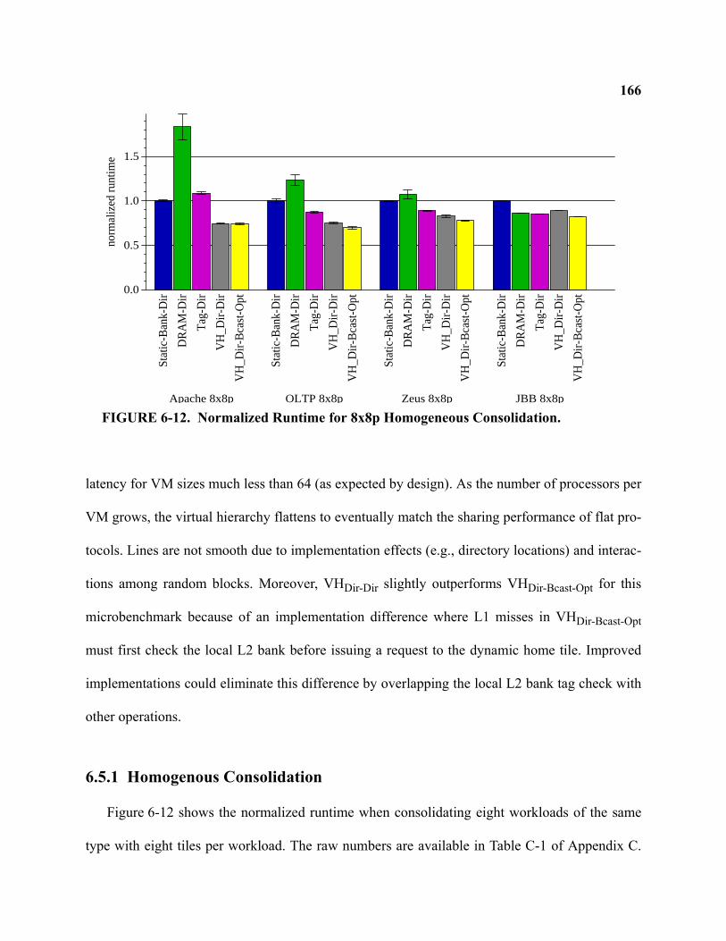
166
latency for VM sizes much less than 64 (as expected by design). As the number of processors per
VM grows, the virtual hierarchy flattens to eventually match the sharing performance of flat pro-
tocols. Lines are not smooth due to implementation effects (e.g., directory locations) and interac-
tions among random blocks. Moreover, VHDir-Dir slightly outperforms VHDir-Bcast-Opt for this
microbenchmark because of an implementation difference where L1 misses in VHDir-Bcast-Opt
must first check the local L2 bank before issuing a request to the dynamic home tile. Improved
implementations could eliminate this difference by overlapping the local L2 bank tag check with
other operations.
6.5.1 Homogenous Consolidation
Figure 6-12 shows the normalized runtime when consolidating eight workloads of the same
type with eight tiles per workload. The raw numbers are available in Table C-1 of Appendix C.
0.0
0.5
1.0
1.5
norm
aliz
ed r
untim
e
Sta
tic-B
ank-
Dir
DR
AM
-Dir
Tag
-Dir
VH
_Dir-
Dir
VH
_Dir-
Bca
st-O
pt
Apache 8x8p
Sta
tic-B
ank-
Dir
DR
AM
-Dir
Tag
-Dir
VH
_Dir-
Dir
VH
_Dir-
Bca
st-O
pt
OLTP 8x8pS
tatic
-Ban
k-D
ir
DR
AM
-Dir
Tag
-Dir
VH
_Dir-
Dir
VH
_Dir-
Bca
st-O
pt
Zeus 8x8p
Sta
tic-B
ank-
Dir
DR
AM
-Dir
Tag
-Dir
VH
_Dir-
Dir
VH
_Dir-
Bca
st-O
pt
JBB 8x8p
FIGURE 6-12. Normalized Runtime for 8x8p Homogeneous Consolidation.
167DRAM-DIR performs the worst for all workloads except JBB. This is because of the long indirec-
tion latency when incurring a miss in the directory caches. DRAM-DIR achieves a directory cache
hit rate of 43%, 49%, 62%, and 65% for Apache, OLTP, Zeus, and JBB respectively. STATIC-
BANK-DIR is generally the next best-performing baseline protocol. TAG-DIR, with its arguably
unimplementable 1024-way CAM, outperforms STATIC-BANK-DIR by an additional 12-17% for
OLTP, Zeus, and SpecJBB.
The virtual hierarchy protocols, VHDir-Dir and VHDir-Bcast-Opt, perform the best and achieve
up to 46% faster performance than the best-performing alternative (TAG-DIR) for the 8x8p
homogenous runs. In particular, VHDir-Dir performs 7-45% faster than TAG-DIR for Apache,
OLTP, and Zeus. TAG-DIR manages to outperform VHDir-Dir by 4% for SpecJBB. This is because
TAG-DIR frequently accesses data from tiles’ local L2 banks whereas VHDir-Dir interleaves L2
capacity across dynamic home tiles. Compared to VHDir-Dir, VHDir-Bcast-Opt gains an additional 6-
8% for OLTP, Zeus, and SpecJBB. The modest improvements of VHDir-Bcast-Opt over VHDir-Dir
come from the optimizations that VHDir-Bcast-Opt implements. Compared to the more realistic
STATIC-BANK-DIR baseline, VHDir-Bcast-Opt performs 34%, 42%, 28%, and 22% faster for
Apache, OLTP, Zeus, and SpecJBB respectively.
To gain further insights into the performance differences, Figure 6-13 shows the breakdown of
memory system stall cycles and Table C-1 in Appendix C shows the raw counts. The bars in the
figure show the normalized amount of cycles spent servicing off-chip misses to DRAM, hits in
the local L2 bank, and hits in caches of remote tiles. The figure indicates that off-chip DRAM
misses contribute to the majority of time spent in the memory system. Consequently, using a
larger backing L3 cache for future many-core CMPs, as suggested by Intel [64], may be especially
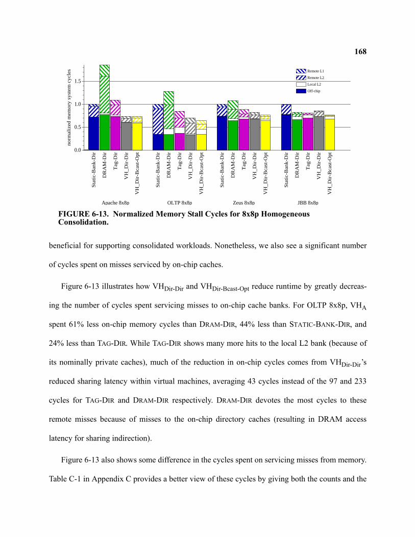
168
beneficial for supporting consolidated workloads. Nonetheless, we also see a significant number
of cycles spent on misses serviced by on-chip caches.
Figure 6-13 illustrates how VHDir-Dir and VHDir-Bcast-Opt reduce runtime by greatly decreas-
ing the number of cycles spent servicing misses to on-chip cache banks. For OLTP 8x8p, VHA
spent 61% less on-chip memory cycles than DRAM-DIR, 44% less than STATIC-BANK-DIR, and
24% less than TAG-DIR. While TAG-DIR shows many more hits to the local L2 bank (because of
its nominally private caches), much of the reduction in on-chip cycles comes from VHDir-Dir’s
reduced sharing latency within virtual machines, averaging 43 cycles instead of the 97 and 233
cycles for TAG-DIR and DRAM-DIR respectively. DRAM-DIR devotes the most cycles to these
remote misses because of misses to the on-chip directory caches (resulting in DRAM access
latency for sharing indirection).
Figure 6-13 also shows some difference in the cycles spent on servicing misses from memory.
Table C-1 in Appendix C provides a better view of these cycles by giving both the counts and the
0.0
0.5
1.0
1.5
no
rma
lize
d m
em
ory
sys
tem
cyc
les
Remote L1
Remote L2
Local L2
Off-chipS
tatic
-Ba
nk-
Dir
DR
AM
-Dir
Ta
g-D
ir
VH
_D
ir-D
ir
VH
_D
ir-B
cast
-Op
t
Apache 8x8p
Sta
tic-B
an
k-D
ir
DR
AM
-Dir
Ta
g-D
ir
VH
_D
ir-D
ir
VH
_D
ir-B
cast
-Op
tOLTP 8x8p
Sta
tic-B
an
k-D
ir
DR
AM
-Dir
Ta
g-D
ir
VH
_D
ir-D
ir
VH
_D
ir-B
cast
-Op
t
Zeus 8x8p
Sta
tic-B
an
k-D
ir
DR
AM
-Dir
Ta
g-D
ir
VH
_D
ir-D
ir
VH
_D
ir-B
cast
-Op
t
JBB 8x8p
FIGURE 6-13. Normalized Memory Stall Cycles for 8x8p Homogeneous Consolidation.
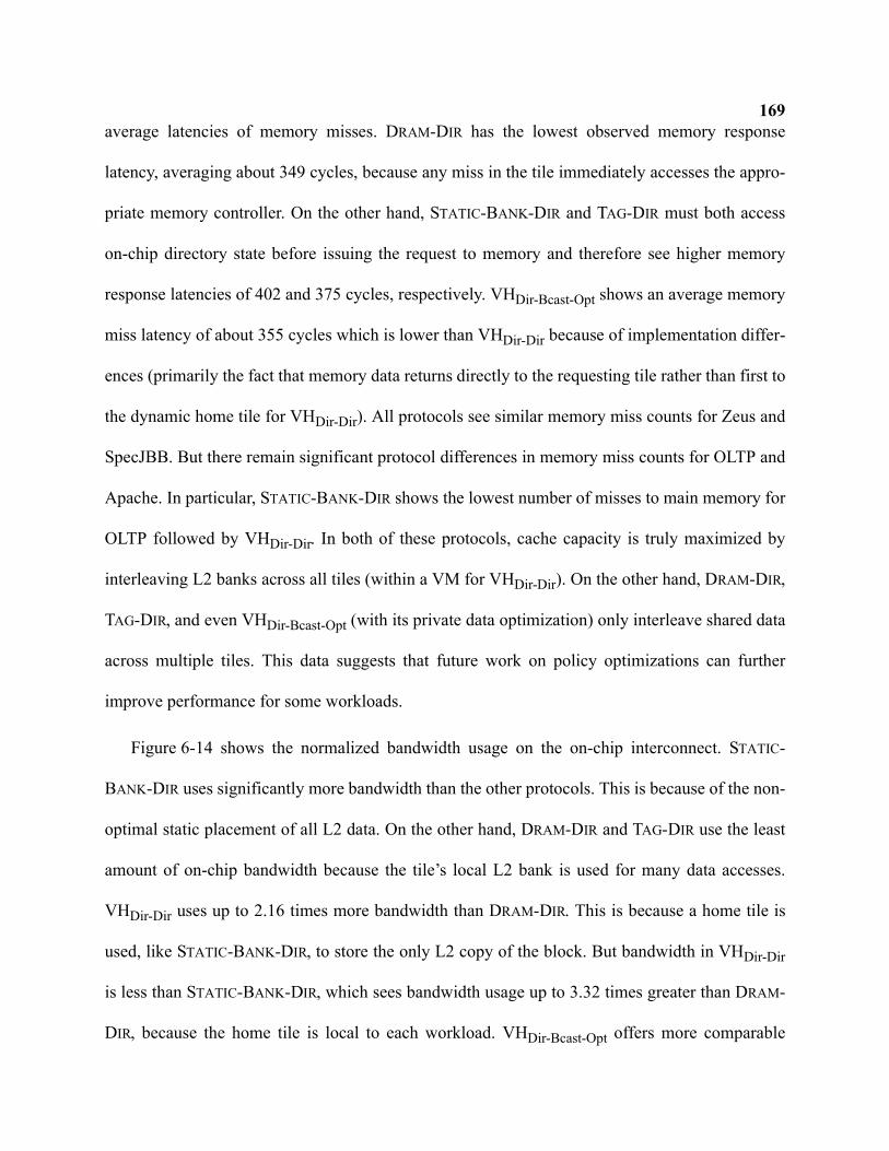
169average latencies of memory misses. DRAM-DIR has the lowest observed memory response
latency, averaging about 349 cycles, because any miss in the tile immediately accesses the appro-
priate memory controller. On the other hand, STATIC-BANK-DIR and TAG-DIR must both access
on-chip directory state before issuing the request to memory and therefore see higher memory
response latencies of 402 and 375 cycles, respectively. VHDir-Bcast-Opt shows an average memory
miss latency of about 355 cycles which is lower than VHDir-Dir because of implementation differ-
ences (primarily the fact that memory data returns directly to the requesting tile rather than first to
the dynamic home tile for VHDir-Dir). All protocols see similar memory miss counts for Zeus and
SpecJBB. But there remain significant protocol differences in memory miss counts for OLTP and
Apache. In particular, STATIC-BANK-DIR shows the lowest number of misses to main memory for
OLTP followed by VHDir-Dir. In both of these protocols, cache capacity is truly maximized by
interleaving L2 banks across all tiles (within a VM for VHDir-Dir). On the other hand, DRAM-DIR,
TAG-DIR, and even VHDir-Bcast-Opt (with its private data optimization) only interleave shared data
across multiple tiles. This data suggests that future work on policy optimizations can further
improve performance for some workloads.
Figure 6-14 shows the normalized bandwidth usage on the on-chip interconnect. STATIC-
BANK-DIR uses significantly more bandwidth than the other protocols. This is because of the non-
optimal static placement of all L2 data. On the other hand, DRAM-DIR and TAG-DIR use the least
amount of on-chip bandwidth because the tile’s local L2 bank is used for many data accesses.
VHDir-Dir uses up to 2.16 times more bandwidth than DRAM-DIR. This is because a home tile is
used, like STATIC-BANK-DIR, to store the only L2 copy of the block. But bandwidth in VHDir-Dir
is less than STATIC-BANK-DIR, which sees bandwidth usage up to 3.32 times greater than DRAM-
DIR, because the home tile is local to each workload. VHDir-Bcast-Opt offers more comparable
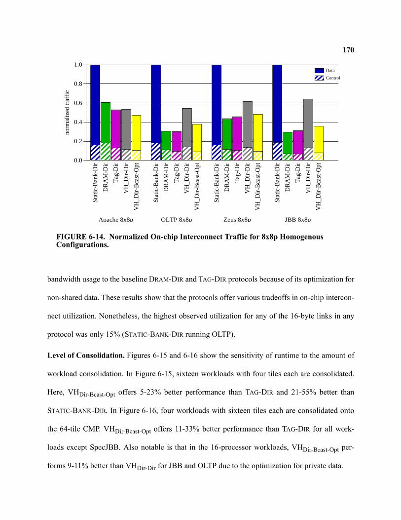
170
bandwidth usage to the baseline DRAM-DIR and TAG-DIR protocols because of its optimization for
non-shared data. These results show that the protocols offer various tradeoffs in on-chip intercon-
nect utilization. Nonetheless, the highest observed utilization for any of the 16-byte links in any
protocol was only 15% (STATIC-BANK-DIR running OLTP).
Level of Consolidation. Figures 6-15 and 6-16 show the sensitivity of runtime to the amount of
workload consolidation. In Figure 6-15, sixteen workloads with four tiles each are consolidated.
Here, VHDir-Bcast-Opt offers 5-23% better performance than TAG-DIR and 21-55% better than
STATIC-BANK-DIR. In Figure 6-16, four workloads with sixteen tiles each are consolidated onto
the 64-tile CMP. VHDir-Bcast-Opt offers 11-33% better performance than TAG-DIR for all work-
loads except SpecJBB. Also notable is that in the 16-processor workloads, VHDir-Bcast-Opt per-
forms 9-11% better than VHDir-Dir for JBB and OLTP due to the optimization for private data.
0.0
0.2
0.4
0.6
0.8
1.0no
rmal
ized
traf
ficData
Control
Sta
tic-B
ank-
Dir
DR
AM
-Dir
Tag
-Dir
VH
_Dir-
Dir
VH
_Dir-
Bca
st-O
pt
Apache 8x8p
Sta
tic-B
ank-
Dir
DR
AM
-Dir
Tag
-Dir
VH
_Dir-
Dir
VH
_Dir-
Bca
st-O
pt
OLTP 8x8pS
tatic
-Ban
k-D
ir
DR
AM
-Dir
Tag
-Dir
VH
_Dir-
Dir
VH
_Dir-
Bca
st-O
pt
Zeus 8x8p
Sta
tic-B
ank-
Dir
DR
AM
-Dir
Tag
-Dir
VH
_Dir-
Dir
VH
_Dir-
Bca
st-O
pt
JBB 8x8p
FIGURE 6-14. Normalized On-chip Interconnect Traffic for 8x8p Homogenous Configurations.
171
Compared to TAG-DIR, the VH protocols show the most performance improvement when sim-
ulating our baseline of eight consolidated workloads of eight tiles each. These 8x8p configura-
tions exhibit enough sharing misses to make the reduced sharing latency of VH pay off. While
smaller four-core workloads allow VH protocols to offer the fastest sharing latency (as shown in
Figure 6-11), there are less sharing misses, in part, because less overall cache capacity is available
to hold the large instruction footprint of these commercial workloads.
0.0
0.5
1.0
1.5no
rmal
ized
run
time
Sta
tic-B
ank-
Dir
DR
AM
-Dir
Tag
-Dir
VH
_Dir-
Dir
VH
_Dir-
Bca
st-O
pt
Apache 16x4p
Sta
tic-B
ank-
Dir
DR
AM
-Dir
Tag
-Dir
VH
_Dir-
Dir
VH
_Dir-
Bca
st-O
pt
OLTP 16x4pS
tatic
-Ban
k-D
ir
DR
AM
-Dir
Tag
-Dir
VH
_Dir-
Dir
VH
_Dir-
Bca
st-O
pt
Zeus 16x4p
Sta
tic-B
ank-
Dir
DR
AM
-Dir
Tag
-Dir
VH
_Dir-
Dir
VH
_Dir-
Bca
st-O
pt
JBB 16x4p
FIGURE 6-15. Normalized Runtime for 16x4p Homogeneous Consolidation.
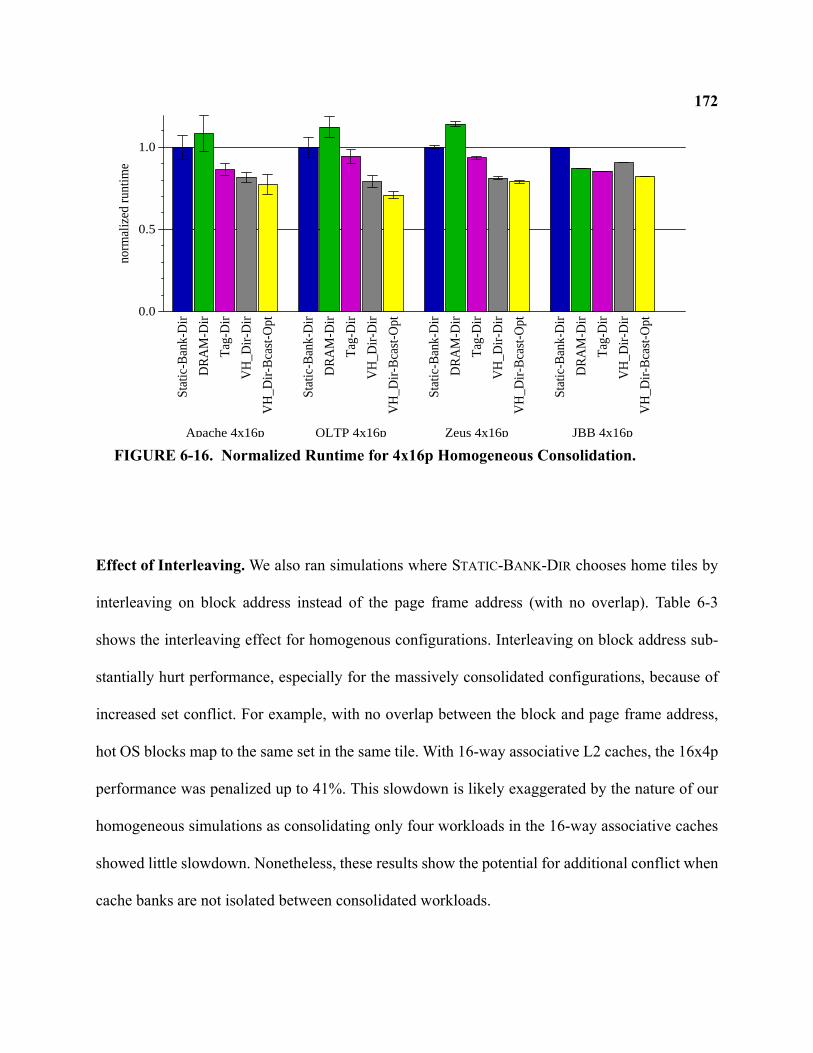
172
Effect of Interleaving. We also ran simulations where STATIC-BANK-DIR chooses home tiles by
interleaving on block address instead of the page frame address (with no overlap). Table 6-3
shows the interleaving effect for homogenous configurations. Interleaving on block address sub-
stantially hurt performance, especially for the massively consolidated configurations, because of
increased set conflict. For example, with no overlap between the block and page frame address,
hot OS blocks map to the same set in the same tile. With 16-way associative L2 caches, the 16x4p
performance was penalized up to 41%. This slowdown is likely exaggerated by the nature of our
homogeneous simulations as consolidating only four workloads in the 16-way associative caches
showed little slowdown. Nonetheless, these results show the potential for additional conflict when
cache banks are not isolated between consolidated workloads.
0.0
0.5
1.0
norm
aliz
ed r
untim
e
Sta
tic-B
ank-
Dir
DR
AM
-Dir
Tag
-Dir
VH
_Dir-
Dir
VH
_Dir-
Bca
st-O
pt
Apache 4x16p
Sta
tic-B
ank-
Dir
DR
AM
-Dir
Tag
-Dir
VH
_Dir-
Dir
VH
_Dir-
Bca
st-O
pt
OLTP 4x16pS
tatic
-Ban
k-D
ir
DR
AM
-Dir
Tag
-Dir
VH
_Dir-
Dir
VH
_Dir-
Bca
st-O
pt
Zeus 4x16p
Sta
tic-B
ank-
Dir
DR
AM
-Dir
Tag
-Dir
VH
_Dir-
Dir
VH
_Dir-
Bca
st-O
pt
JBB 4x16p
FIGURE 6-16. Normalized Runtime for 4x16p Homogeneous Consolidation.

173
Effect of Replication Policy. Table 6-4 shows the effect of increasing replication by always
replacing L1 data into the core’s local L2 bank. As shown, this replication policy had a minor
effect on overall runtime for the 8x8p configurations (and is consistent with data for other config-
urations not shown). This suggests that compensating for non-local coherence through increased
replication is not effective for these workloads. 3
3. We do not implement the additional replication policy for VHDir-Dir because of the complexity entailed in modifying this two-
level directory protocol.
TABLE 6-3. STATIC-BANK-DIR’s Slowdown with Block Address InterleavingApache 16x4p OLTP 16x4p Zeus 16x4p JBB 16x4p
41% 28% 24% 40%Apache 8x8p OLTP 8x8p Zeus 8x8p JBB 8x8p
14% 6% 3% 10%Apache 4x16p OLTP 4x16p Zeus 4x16p JBB 4x16p
8% 0% 1% 2%
TABLE 6-4. Relative Performance Improvement from Low vs. High ReplicationApache 8x8p OLTP 8x8p Zeus 8x8p JBB 8x8p
DRAM-DIR 19.7% 14.4% 9.29% 0.06%STATIC-BANK-DIR -33.0% 3.31% -7.02% -11.2%TAG-DIR 1.27% 3.91% 1.63% -0.22%
VHDir-Dir2 n/a n/a n/a n/a
VHDir-Bcast-Opt -11.0% -5.22% -0.98% -0.12%
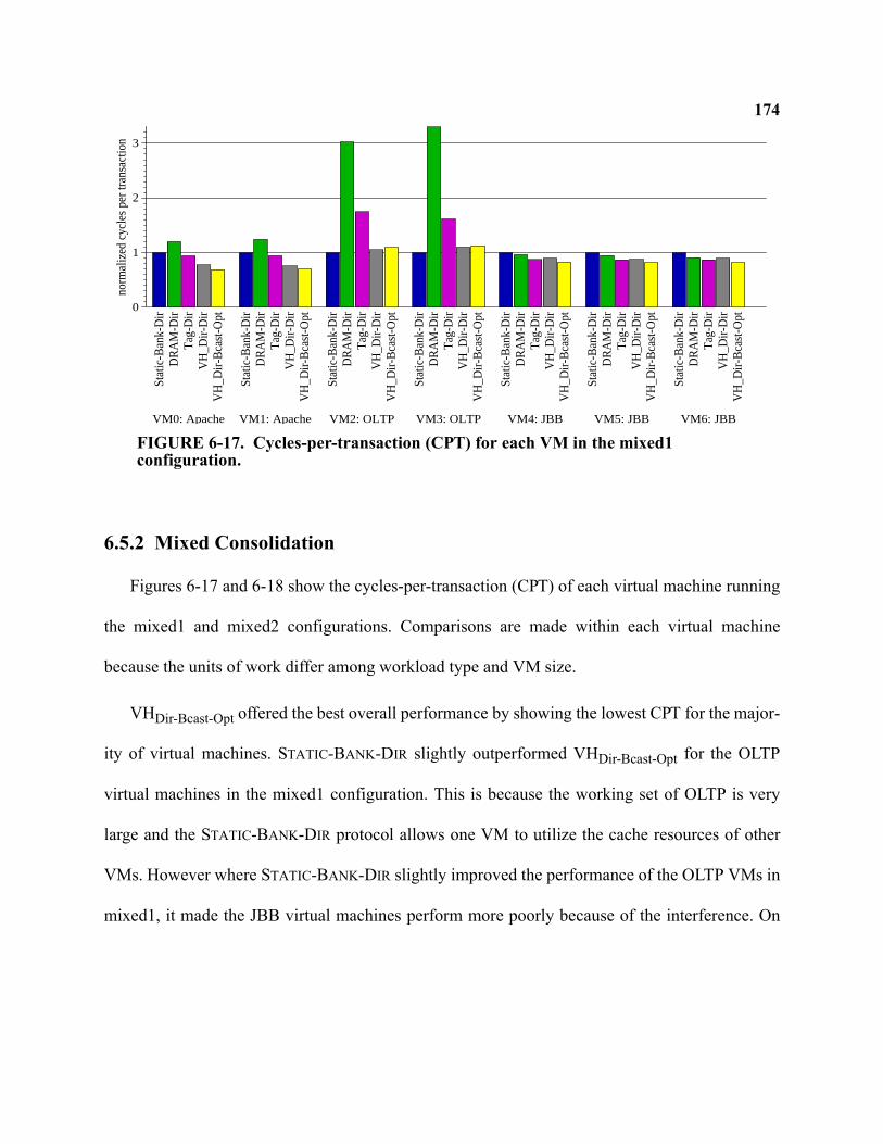
174
6.5.2 Mixed Consolidation
Figures 6-17 and 6-18 show the cycles-per-transaction (CPT) of each virtual machine running
the mixed1 and mixed2 configurations. Comparisons are made within each virtual machine
because the units of work differ among workload type and VM size.
VHDir-Bcast-Opt offered the best overall performance by showing the lowest CPT for the major-
ity of virtual machines. STATIC-BANK-DIR slightly outperformed VHDir-Bcast-Opt for the OLTP
virtual machines in the mixed1 configuration. This is because the working set of OLTP is very
large and the STATIC-BANK-DIR protocol allows one VM to utilize the cache resources of other
VMs. However where STATIC-BANK-DIR slightly improved the performance of the OLTP VMs in
mixed1, it made the JBB virtual machines perform more poorly because of the interference. On
0
1
2
3
norm
aliz
ed c
ycle
s pe
r tr
ansa
ctio
n
Sta
tic-B
ank-
Dir
DR
AM
-Dir
Tag
-Dir
VH
_Dir-
Dir
VH
_Dir-
Bca
st-O
pt
VM0: Apache
Sta
tic-B
ank-
Dir
DR
AM
-Dir
Tag
-Dir
VH
_Dir-
Dir
VH
_Dir-
Bca
st-O
pt
VM1: Apache
Sta
tic-B
ank-
Dir
DR
AM
-Dir
Tag
-Dir
VH
_Dir-
Dir
VH
_Dir-
Bca
st-O
pt
VM2: OLTPS
tatic
-Ban
k-D
irD
RA
M-D
irT
ag-D
irV
H_D
ir-D
irV
H_D
ir-B
cast
-Opt
VM3: OLTP
Sta
tic-B
ank-
Dir
DR
AM
-Dir
Tag
-Dir
VH
_Dir-
Dir
VH
_Dir-
Bca
st-O
pt
VM4: JBB
Sta
tic-B
ank-
Dir
DR
AM
-Dir
Tag
-Dir
VH
_Dir-
Dir
VH
_Dir-
Bca
st-O
pt
VM5: JBB
Sta
tic-B
ank-
Dir
DR
AM
-Dir
Tag
-Dir
VH
_Dir-
Dir
VH
_Dir-
Bca
st-O
pt
VM6: JBB
FIGURE 6-17. Cycles-per-transaction (CPT) for each VM in the mixed1 configuration.
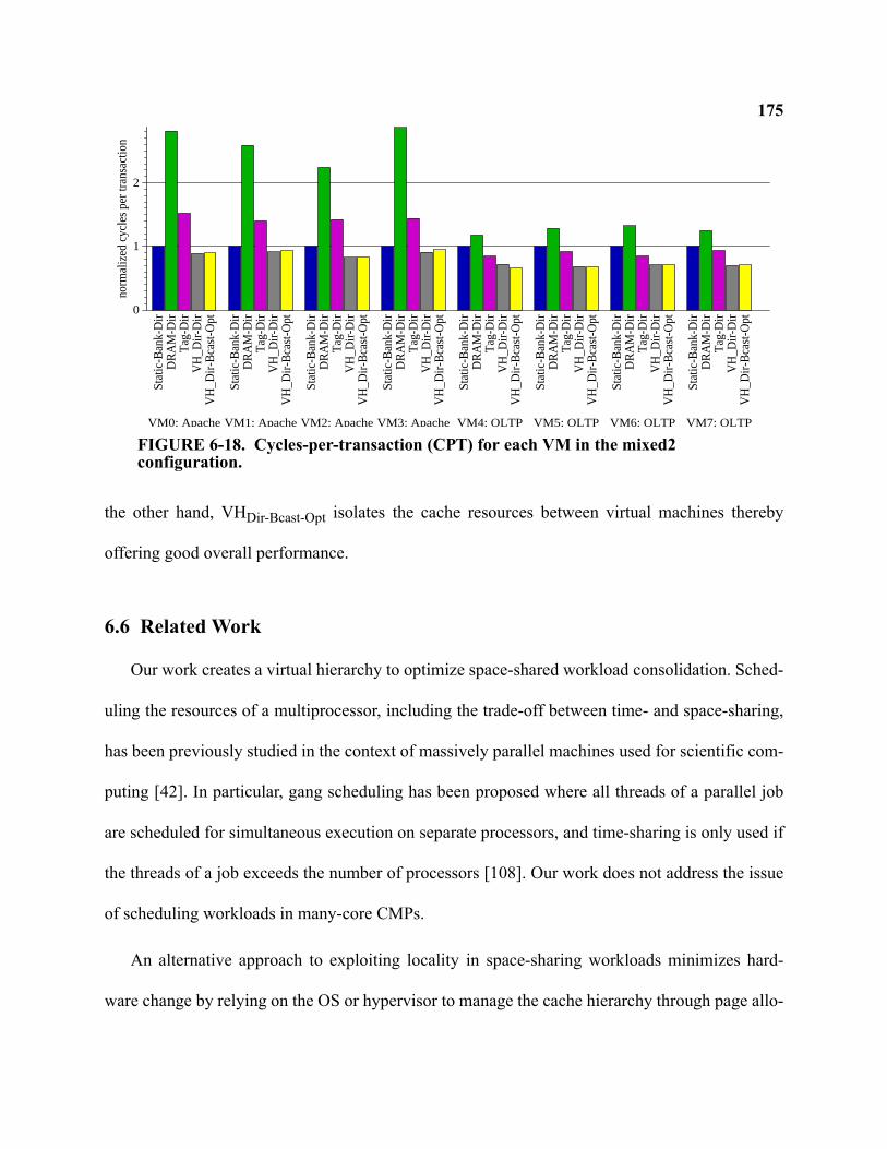
175
the other hand, VHDir-Bcast-Opt isolates the cache resources between virtual machines thereby
offering good overall performance.
6.6 Related Work
Our work creates a virtual hierarchy to optimize space-shared workload consolidation. Sched-
uling the resources of a multiprocessor, including the trade-off between time- and space-sharing,
has been previously studied in the context of massively parallel machines used for scientific com-
puting [42]. In particular, gang scheduling has been proposed where all threads of a parallel job
are scheduled for simultaneous execution on separate processors, and time-sharing is only used if
the threads of a job exceeds the number of processors [108]. Our work does not address the issue
of scheduling workloads in many-core CMPs.
An alternative approach to exploiting locality in space-sharing workloads minimizes hard-
ware change by relying on the OS or hypervisor to manage the cache hierarchy through page allo-
0
1
2
norm
aliz
ed c
ycle
s pe
r tr
ansa
ctio
n
Sta
tic-B
ank-
Dir
DR
AM
-Dir
Tag
-Dir
VH
_Dir-
Dir
VH
_Dir-
Bca
st-O
pt
VM0: Apache
Sta
tic-B
ank-
Dir
DR
AM
-Dir
Tag
-Dir
VH
_Dir-
Dir
VH
_Dir-
Bca
st-O
pt
VM1: Apache
Sta
tic-B
ank-
Dir
DR
AM
-Dir
Tag
-Dir
VH
_Dir-
Dir
VH
_Dir-
Bca
st-O
pt
VM2: Apache
Sta
tic-B
ank-
Dir
DR
AM
-Dir
Tag
-Dir
VH
_Dir-
Dir
VH
_Dir-
Bca
st-O
ptVM3: Apache
Sta
tic-B
ank-
Dir
DR
AM
-Dir
Tag
-Dir
VH
_Dir-
Dir
VH
_Dir-
Bca
st-O
pt
VM4: OLTP
Sta
tic-B
ank-
Dir
DR
AM
-Dir
Tag
-Dir
VH
_Dir-
Dir
VH
_Dir-
Bca
st-O
pt
VM5: OLTP
Sta
tic-B
ank-
Dir
DR
AM
-Dir
Tag
-Dir
VH
_Dir-
Dir
VH
_Dir-
Bca
st-O
pt
VM6: OLTP
Sta
tic-B
ank-
Dir
DR
AM
-Dir
Tag
-Dir
VH
_Dir-
Dir
VH
_Dir-
Bca
st-O
pt
VM7: OLTP
FIGURE 6-18. Cycles-per-transaction (CPT) for each VM in the mixed2 configuration.
176cation. The Cellular Disco [26] hypervisor exploited the structure of the Origin2000 to increase
performance and performance isolation by using NUMA-aware memory allocation to virtual
machines. Cho et al. [34] explore even lower level OS page mapping and allocation strategies in a
system that interleaves cache banks by frame number, like STATIC-BANK-DIR. In contrast, our
proposal frees the OS and hypervisor from managing cache banks and offers greater opportunities
for VM scheduling and reassignment.
Many proposals partition or change the default allocation policy of monolithic shared L2
caches. Some schemes partition the cache based on the replacement policy [74, 125, 126], or par-
tition at the granularity of individual cache sets or ways [32, 111]. Other approaches by Lie et al.
[88] and Varadarajan et al. [135] partition a cache into regions, but neither schemes address coher-
ence between regions. Rafique et al. [110] also propose support to allow the OS to manage the
shared cache. Our VH scheme works at a higher level than managing a single shared cache.
Our work assigns the resources of a tile, including cache banks and processor cores, to virtual
machines (or OS processes). Hsu et al. [58] studied optimality for cache sharing based on various
metrics. Other approaches explicitly manage Quality of Service (QoS) in shared caches. Iyer
examined QoS [67] with mechanisms for thread priorities such as set partitioning, per-thread
cache line counts, and heterogeneous regions. Nesbit et al. develop Virtual Private Caches to man-
age QoS of a single shared L2 cache by applying fair queuing techniques [106]. Applying addi-
tional policies to better balance resources within a virtual machine domain is a topic of future
work.
There has been much previous work in organizing CMP caches to exploit distance locality
through replication or migration. D-NUCA was proposed to improve performance by dynami-
177cally migrating data closer to the cores based on frequency of access. While shown to be effective
in uniprocessor caches [73], the benefits in a CMP are less clear [23]. To our knowledge, there is
no complete, scalable solution for implementing D-NUCA cache coherence in a multiprocessor.
Huh et al. [60] also studied trade-offs in L2 sharing by using a configurable NUCA substrate with
unspecified mapping functions. All of their results relied on a centralized directory like our TAG-
DIR. CMP-NuRapid [33] exploited distance locality by decoupling the data and tag arrays thereby
allowing the flexible placement of data. However their CMP implementation requires a non-scal-
able atomic bus. Other recently proposed replication schemes include Victim Replication [145],
Cooperative Caching [29], and ASR [22]. In Section 6.5.1, we showed how replication is an
orthogonal issue to our work.
Finally, previous commercial systems have offered support for multiprocessor virtualization
and partitioning [30, 57, 68]. Smith and Nair characterize these systems as either supporting phys-
ical or logical partitioning [120]. Physical partitioning enforces the assignment of resources to
partitions based on rigid physical boundaries. Logical partitioning relaxes the rigidity, even offer-
ing the time-sharing of processors. VH offers a new way to space-share the vast cache resources
of future many-core CMPs and applies to either physical or logical partitioning (e.g., time-sharing
can be supported by saving and restoring the VM Config Tables).
6.7 Future Work
Virtual hierarchies was developed as a mechanism for optimizing memory systems for server
consolidation. But memory system hierarchies have always been fundamental to the design of
computing systems. The principal of locality states that most programs do not access all code or
178data uniformly. Virtual hierarchies could offer a powerful mechanism to adjust the on-chip cache
hierarchy to optimize for single workloads, and future work could explore this.
We developed virtual hierarchies targeted towards a tiled architecture like shown in Figure 6-
1. Other organizations could also benefit from a virtual hierarchy. For example, instead of com-
bined tiles containing a core and cache banks, a dancehall organization could place all processing
cores on one side of the CMP and all cache banks on another side. A virtual hierarchy could then
flexibly adapt the number of cache banks assigned to a set of cores.
Another avenue of future work extends the VH protocols for automatic operation without any
software configuration. While the responsibility of setting a VM Config Table is minimal and
wouldn’t increase OS complexity much, automatic operation could open up more opportunities to
create virtual hierarchies tailored to certain regions of memory. For example, a virtual hierarchy
could be on structured on a per-page basis. Pages shared by all VMs would have a different hier-
archy from VM-private pages. Creating the per-page hierarchies could be automatically accom-
plished by hardware with structures that track which cores share a particular page. Since the
second-level of coherence guarantees correctness, selecting incorrect dynamic home tiles based
on a misprediction is tolerable.
Our work on virtual hierarchies assumes cache and processor resources are equally assigned
to VMs. While this assumption may work well for a majority of consolidated workloads, a more
optimal approach would require a more flexible assignment. For example, one VM may have a
larger working set than another VM. Overall throughput improvements could be seen if the mem-
ory system allowed more cache resources devoted to VMs where needed. One mechanism for
doing so is already supported by our VH protocols. The hypervisor could simply set the VM Con-
179fig Tables to include more tiles than are actually scheduled. Thus VM Config Tables on proces-
sors running threads from separate VMs could simply have overlapping tile configurations.
However further work is needed to develop other mechanisms to share cache between workloads.
Our virtual hierarchy system provides a mechanism to offer performance isolation between
workloads. However it also assumes other shared resources, like memory controllers and inter-
connect links for transferring memory data, have fairness mechanisms (like fair queueing [105]).
Moreover, while our VH protocols provide improved performance isolation amongst workloads,
we do not attempt to provide strong guarantees of Quality-of-Service (QoS). Future work could
develop stronger QoS mechanisms and policies.
Finally, our VH protocols are arguably complex. One reason for the complexity is that we
assume a completely unordered on-chip interconnect. Even point-to-point ordering, given by
deterministic routing algorithms, may have the potential to simplify the protocols because less
races can occur.
6.8 Conclusion
Abundant cores per chip will encourage greater use of space sharing, where work stays on a
group of cores for long time intervals. We propose virtual hierarchies as a new way to space-share
the resources of CMPs. Instead of building a physical hierarchy that cannot adapt to the workload
or mix or workloads, we advocate overlaying a virtual hierarchy onto a physically-flat system.
Our virtual hierarchy can adapt to how workloads space-share the resources of a CMP. In apply-
ing virtual hierarchies to consolidated server workloads, we show how we can improve perfor-
mance and performance isolation while still supporting globally shared memory to facilitate
dynamic partitioning and content-based page sharing.
180Chapter 7
Summary and Reflections
The transition to multicore processors places great focus and importance on memory system
design. The cache coherence mechanisms are a key component toward achieving the goal of con-
tinuing exponential performance growth through widespread thread-level parallelism. This disser-
tation makes several contributions in the space of cache coherence for multicore chips. In this
chapter, we summarize the contributions (Section 7.1). Then in Section 7.2, I offer some reflec-
tions and opinions based on this research. Future work was previously discussed in Sections 4.5,
5.6 and 6.7.
7.1 Summary
This dissertation addresses three different problem areas that all deal with cache coherence in
multicore processors. First, we recognized that rings are emerging as a preferred on-chip intercon-
nect. Existing snooping protocols for rings either used a performance-costly ordering point to re-
establish a total order, or they issued an unbounded number of retries to handle conflicting
requests. We contributed a new cache coherence protocol that exploits a ring’s natural round-
robin order. In doing so, we showed how our new protocol achieves both fast performance and
performance stability—a combination not found in prior designs.
Second, we explored cache coherence protocols for systems constructed with several multi-
core chips. In these Multiple-CMP systems, coherence must occur both within a multicore (intra-
181CMP coherence) and among multicores (inter-CMP coherence). Applying hierarchical coherence
protocols greatly increases complexity, especially when a bus is not relied upon for the first-level
of coherence. We first contributed a hierarchical coherence protocol, DirectoryCMP, that uses two
directory-based protocols bridged together to create a highly scalable system. We then contributed
TokenCMP, which extends token coherence, to create a Multiple-CMP system that is flat for cor-
rectness yet hierarchical for performance. We qualitatively argued how TokenCMP reduces com-
plexity, and our simulation results demonstrated comparable or better performance than
DirectoryCMP.
Third, we contributed the idea of virtual hierarchies for designing memory systems optimized
for space sharing. With future chips containing abundant cores, the opportunities for space shar-
ing the resources will only increase. Our contribution targeted consolidated server workloads on a
tiled many-core chip. We first showed how existing flat coherence protocols failed to accomplish
the memory system goals we identified. Then, we imposed a two-level virtual coherence and
caching hierarchy on a physically flat many-core chip that harmonized with workload assignment.
In doing so, we improved performance by exploiting the locality of space sharing, we provided
performance isolation between workloads, and we maintained globally shared memory to support
advanced virtualization features such as dynamic partitioning and content-based page sharing.
Moreover, virtual hierarchies are a compelling alternative to building hard-wired physical hierar-
chies.
7.2 Reflections
In this section, I reflect on my dissertation research with the benefit of hindsight and the free-
dom to make statements of opinion.
182My assumption of emerging ring-based interconnects is likely correct based on recent conver-
sations with those in industry about upcoming products and designs. Our proposed RING-ORDER
protocol timely tackles the subtle issue of coherence ordering in a ring. It offers a unique round-
robin ordering that synergistically matches a ring. Moreover, RING-ORDER’s round-robin ordering
offers superior predictability and fairness, issues that may even be more attractive in other spaces
such as real-time embedded systems.
We developed and evaluated our ring-based protocols assuming a unidirectional ring. How-
ever it appears that forthcoming chips will instead use bidirectional rings. A bidirectional ring
reduces the average latency between endpoints from N/2 hops to N/4. While Chapter 4 outlines
how RING-ORDER can correctly take advantage of a bidirectional ring by sending data on the
shortest path, the disadvantage of an alternative design that uses an ordering point diminishes.
Nonetheless, ordering points entail additional complexity and I maintain that the other alternative
of using probabilistic coherence protocols should be avoided1.
Our work on TokenCMP developed a system with the appealing property of being flat for cor-
rectness, allowing the system to be model-checked. In Chapter 5, we discussed many remaining
challenges and directions for future work, including addressing a key issue of timeouts and
retries. However even if solved, the realities of technology and industrial design practices may
limit the applicability of TokenCMP. Our end-to-end approach to token counting may not apply to
write-through L1 caches (which appear to remain as the defacto industry approach). Moreover,
the system-level interconnect is typically designed separately from the chip itself. Thus future-
1. While IBM appears to implement such a protocol that uses unbounded retries, it likely uses another software or hardware
mechanism to ensure forward progress. Adding these backup mechanisms only adds to design complexity and problems with
performance stability.
183generation multicore chips may need to function with today’s system-level interconnect specifica-
tions. In my personal opinion, I also question the value in continuing to offer cache coherent
shared memory across multiple chips. Our existing operating systems and programming para-
digms will already be strained to utilize and manage the resources of a single multicore chip that
may soon support dozens of hardware threads. Managing threads over multiple chips with a single
OS image seems dubious especially when considering emerging reliability issues. Thus while
integrating several processor chips onto a board or system may continue to offer cost benefits,
maintaining cache coherent shared memory in hardware may not be required.
In retrospect, I believe the ideas of TokenCMP may actually more readily apply to hierarchi-
cal coherence within a chip instead of between chips. In this realm, designers have the most free-
dom to implement new techniques not amenable to interfacing with legacy system-level standards
and programmers still want to use shared memory for programs running on a single multicore.
I believe that my contribution on virtual hierarchies offers the most potential for impacting
industry and academia. It combines workload trends with emerging technology and design trends.
There is a plethora of research that tackles many multicore issues including cache coherence,
cache replication and placement policies, quality-of-service, and more. Much of this pre-existing
research treats these issues in isolation. For example, many proposals address cache partitioning
without discussing the impact on cache coherence. And many recent cache coherence protocols
do not consider how their scheme would interact with new cache policies for replication. A virtual
hierarchy is an elegant solution that combines many of these issues in a framework familiar to
computer architects (memory hierarchies).
184Finally I reflect on the development and evaluation process used in my dissertation research.
The Wisconsin GEMS toolset, along with our commercial workload suite, served as a vehicle for
evaluating research ideas. However it also enabled me to rapidly explore new ideas. I found rea-
soning about protocol design difficult without the iterative development process afforded by
GEMS. The SLICC language allowed me to quickly specify a protocol (often incomplete) and to
observe system behavior with a random tester. By seeing what actually happens, I was able to
“pop up” a level and reason more carefully about the protocol’s overall correctness and design for
future iterations. In other words, rapidly prototyping protocols allowed me to refine higher-level
ideas instead of carefully engineering a known system. Using such a simulator certainly has its
disadvantages: my specifications may contain latent bugs not caught in my relatively short simu-
lation runs; I often lamented on how SLICC limited my ability to simulate aspects in more detail
(like a pipelined coherence controller); and I often wondered if our existing commercial work-
loads designed for SMPs did not offer the behavior of next-generation workloads for multicore
chips. But evaluating ideas in our field of computer architecture is difficult. It is not possible to
build prototypes without significant manpower and expenditures and even building simulation
infrastructure is a large undertaking for a graduate student. I’ve learned that part of being a suc-
cessful researcher in the field of computer architecture is knowing when to make the right approx-
imations and in knowing how to leverage as much pre-existing infrastructure work as possible.
185
References
[1] P. Abad, V. Puente, P. Prieto, and J. A. Gregorio. Rotary Router: An Efficient Architecture forCMP Interconnect Networks. In Proceedings of the 34th Annual International Symposium onComputer Architecture, June 2007.
[2] D. Abts, D. J. Lilja, and S. Scott. So Many States, So Little Time: Verifying Memory Coherence inthe Cray X1. In Proceedings of the 17th International Parallel and Distributed Processing Sympo-sium (IPDPS), Apr. 2003.
[3] S. V. Adve and K. Gharachorloo. Shared Memory Consistency Models: A Tutorial. IEEE Com-puter, 29(12):66–76, Dec. 1996.
[4] A. Agarwal, R. Simoni, M. Horowitz, and J. Hennessy. An Evaluation of Directory Schemes forCache Coherence. In Proceedings of the 15th Annual International Symposium on ComputerArchitecture, pages 280–289, May 1988.
[5] V. Agarwal, M. S. Hrishikesh, S. W. Keckler, and D. Burger. Clock Rate versus IPC: The End ofthe Road for Conventional Microarchitectures. In Proceedings of the 27th Annual InternationalSymposium on Computer Architecture, pages 248–259, June 2000.
[6] N. Aggarwal, P. Ranganathan, N. P. Jouppi, and J. E. Smith. Configurable Isolation: Building HighAvailability Systems with Commodity Multi-Core Processors. In Proceedings of the 34th AnnualInternational Symposium on Computer Architecture, June 2007.
[7] A. Ahmed, P. Conway, B. Hughes, and F. Weber. AMD Opteron Shared Memory MP Systems. InProceedings of the 14th HotChips Symposium, Aug. 2002.
[8] A. R. Alameldeen, M. M. K. Martin, C. J. Mauer, K. E. Moore, M. Xu, D. J. Sorin, M. D. Hill, andD. A. Wood. Simulating a $2M Commercial Server on a $2K PC. IEEE Computer, 36(2):50–57,Feb. 2003.
[9] A. R. Alameldeen and D. A. Wood. Variability in Architectural Simulations of Multi-threadedWorkloads. In Proceedings of the Ninth IEEE Symposium on High-Performance Computer Archi-tecture, pages 7–18, Feb. 2003.
[10] A. R. Alameldeen and D. A. Wood. IPC Considered Harmful for Multiprocessor Workloads. IEEEMicro, 26(4):8–17, Jul/Aug 2006.
[11] AMD. AMD64 Virtualization Codenamed Pacifica Technology: Secure Virtual Machine Architec-ture Reference Manual, May 2005.
[12] AMD Press Release. AMD Introduces the World’s Most Advanced x86 Processor, Designed forthe Demanding Datacenter. http://www.amd.com/us-en/Corporate/VirtualPressRoom/0,,51_104_543_15008 119% 768,00.html, Sept. 2007.
186[13] Andrew W. Wilson Jr. Hierarchical Cache/Bus Architecture for Shared Memory Multiprocessors.
In Proceedings of the 14th Annual International Symposium on Computer Architecture, pages244–252, June 1987.
[14] J. Archibald and J.-L. Baer. An Economical Solution to the Cache Coherence Problem. In Pro-ceedings of the 11th Annual International Symposium on Computer Architecture, pages 355–362,June 1984.
[15] K. Asanovic, R. Bodik, B. C. Catanzaro, J. J. Gebis, P. Husbands, K. Keutzer, D. A. Patterson,W. L. Plishker, J. Shalf, S. W. Williams, and K. A. Yelick. The Landscape of Parallel ComputingResearch: A View from Berkeley. Technical Report Technical Report No. UCB/EECS-2006-183,EECS Department, University of California, Berkeley, 2006.
[16] R. R. Atkinson and E. M. McCreight. The Dragon Processor.
[17] L. A. Barroso and M. Dubois. Cache Coherence on a Slotted Ring. In Proceedings of the Interna-tional Conference on Parallel Processing, pages 230–237, Aug. 1991.
[18] L. A. Barroso and M. Dubois. The Performance of Cache-Coherent Ring-based Multiprocessors.In Proceedings of the 20th Annual International Symposium on Computer Architecture, pages268–277, May 1993.
[19] L. A. Barroso and K. Gharachorloo. Personal Communication, June 2003.
[20] L. A. Barroso, K. Gharachorloo, R. McNamara, A. Nowatzyk, S. Qadeer, B. Sano, S. Smith,R. Stets, and B. Verghese. Piranha: A Scalable Architecture Based on Single-Chip Multiprocess-ing. In Proceedings of the 27th Annual International Symposium on Computer Architecture, pages282–293, June 2000.
[21] L. A. Barroso, K. Gharachorloo, M. Ravishankar, and R. Stets. Managing Complexity in the Pira-nha Server-Class Processor Design. In 2nd Workshop on Complexity-Effective Design held in con-junction with the 27th International Symposium on Computer Architecture, June 2001.
[22] B. M. Beckmann, M. R. Marty, and D. A. Wood. ASR: Adaptive Selective Replication for CMPCaches. In Proceedings of the 39th Annual IEEE/ACM International Symposium on Microarchi-tecture, Dec. 2006.
[23] B. M. Beckmann and D. A. Wood. Managing Wire Delay in Large Chip-Multiprocessor Caches.In Proceedings of the 37th Annual IEEE/ACM International Symposium on Microarchitecture,Dec. 2004.
[24] B. H. Bloom. Space/Time Trade-offs in Hash Coding with Allowable Errors. Communications ofthe ACM, 13(7):422–426, July 1970.
[25] S. Borkar. Designing Reliable Systems from Unreliable Components: the Challenges of TransistorVariability and Degradation. IEEE Micro, 25(6):10–16, Nov. 2005.
187[26] E. Bugnion, S. Devine, K. Govil, and M. Rosenblum. Disco: Running Commodity Operating Sys-
tems on Scalable Multiprocessors. ACM Transactions on Computer Systems, 15(4):319–349, Nov.1997.
[27] H. Burkhardt, S. Frank, B. Knobe, and J. Rothnie. Overview of the KSR 1 computer system. Tech-nical Report KSR-TR-9202001, Kendall Square Research, 1992.
[28] L. M. Censier and P. Feautrier. A New Solution to Coherence Problems in Multicache Systems.IEEE Transactions on Computers, C-27(12):1112–1118, Dec. 1978.
[29] J. Chang and G. S. Sohi. Cooperative Caching for Chip Multiprocessors. In Proceedings of the33nd Annual International Symposium on Computer Architecture, June 2006.
[30] A. Charlesworth. Starfire: Extending the SMP Envelope. IEEE Micro, 18(1):39–49, Jan/Feb 1998.
[31] L. Cheng, N. Muralimanohar, K. Ramani, R. Balasubramonian, and J. B. Carter. Interconnect-Aware Coherence Protocols for Chip Multiprocessors. In Proceedings of the 33nd Annual Interna-tional Symposium on Computer Architecture, June 2006.
[32] D. Chiou, P. Jain, S. Devadas, and L. Rudolph. Dynamic Cache Partitioning via Columnization. InProceedings of Design Automation Conference, June 2000.
[33] Z. Chishti, M. D. Powell, and T. N. Vijaykumar. Optimizing Replication, Communication, andCapacity Allocation in CMPs. In Proceedings of the 32nd Annual International Symposium onComputer Architecture, June 2005.
[34] S. Cho and L. Jin. Managing Distributed, Shared L2 Caches through OS-Level Page Allocation. InProceedings of the 39th Annual IEEE/ACM International Symposium on Microarchitecture, Dec.2006.
[35] S. W. Chung, S. T. Jhang, and C. S. Jhon. PANDA: ring-based multiprocessor system using newsnooping protocol. In International Conference on Parallel and Distributed Systems, pages 10–17,1998.
[36] E. Clarke and E. Emerson. Design and Synthesis of Synchronization Skeletons using BranchingTime Temporal Logic. In D. Kozen, editor, Proceedings of the Workshop on Logics of Programs,volume 131 of Lecture Notes in Computer Science, pages 52–71, Yorktown Heights, New York,May 1981. Springer-Verlag.
[37] A. L. Cox and R. J. Fowler. Adaptive Cache Coherency for Detecting Migratory Shared Data. InProceedings of the 20th Annual International Symposium on Computer Architecture, pages 98–108, May 1993.
[38] W. J. Dally and B. Towles. Route Packets, Not Wires: On-Chip Interconnection Networks. InDesign Automation Conference, pages 684–689, 2001.
[39] W. J. Dally and B. P. Towles. Principles and Practices of Interconnection Networks. Morgan Kauf-mann, 2003.
188[40] N. Enright-Jerger, M. Lipasti, and L.-S. Peh. Circuit-Switched Coherence. 6(1), Mar. 2007.
[41] K. Farkas, Z. Vranesic, and M. Stumm. Scalable Cache Consistency for Hierarchically StructuredMultiprocessors. The Journal of Supercomputing, 8(4), 1995.
[42] D. G. Feitelson. Job Scheduling in Multiprogrammed Parallel Systems. Technical report, IBMResearch Report, Oct. 1994.
[43] R. Fernandez-Pascual, J. M. Garcia, M. E. Acacio, and J. Duato. A Low Overhead Fault TolerantCoherence Protocol for CMP Architectures. In Proceedings of the Thirteenth IEEE Symposium onHigh-Performance Computer Architecture, Feb. 2007.
[44] I. T. R. for Semiconductors. ITRS 2005 Edition. Semiconductor Industry Association, 2005. http://www.itrs.net/Common/2005ITRS/Home2005.htm.
[45] S. Frank, H. Burkhardt, III, and J. Rothnie. The KSR1: Bridging the Gap Between Shared Memoryand MPPs. In Proceedings of the 38th Annual IEEE Computer Society Computer Conference(COMPCON), pages 285–295, Feb. 1993.
[46] S. J. Frank. Tightly Coupled Multiprocessor System Speeds Memory-access Times. Electronics,57(1):164–169, Jan. 1984.
[47] S. J. Frank, H. Burkhardt, L. O. Lee, N. Goodman, B. I. Margulies, and F. D. Weber. Multiproces-sor Digital Data Processing System, Oct. 1991. U.S. Patent 5,055,999.
[48] K. Gharachorloo, L. A. Barroso, and A. Nowatzyk. Efficient ECC-Based Directory Implementa-tions for Scalable Multiprocessors. In Proceedings of the 12th Symposium on Computer Architec-ture and High-Performance Computing (SBAC-PAD 2000), Oct. 2000.
[49] K. Gharachorloo, D. Lenoski, J. Laudon, P. Gibbons, A. Gupta, and J. Hennessy. Memory Consis-tency and Event Ordering in Scalable Shared-Memory. In Proceedings of the 17th Annual Interna-tional Symposium on Computer Architecture, pages 15–26, May 1990.
[50] J. R. Goodman. Using Cache Memory to Reduce Processor-Memory Traffic. In Proceedings of the10th Annual International Symposium on Computer Architecture, pages 124–131, June 1983.
[51] A. Gupta and W.-D. Weber. Cache Invalidation Patterns in Shared-Memory Multiprocessors. IEEETransactions on Computers, 41(7):794–810, July 1992.
[52] A. Gupta, W.-D. Weber, and T. Mowry. Reducing Memory and Traffic Requirements for ScalableDirectory-Based Cache Coherence Schemes. In International Conference on Parallel Processing(ICPP), volume I, pages 312–321, 1990.
[53] D. Gustavson. The Scalable Coherent Interface and related standards projects. IEEE Micro,12(1):10–22, Feb. 1992.
[54] E. Hagersten and M. Koster. WildFire: A Scalable Path for SMPs. In Proceedings of the FifthIEEE Symposium on High-Performance Computer Architecture, pages 172–181, Jan. 1999.
189[55] E. Hagersten, A. Landin, and S. Haridi. DDM–A Cache-Only Memory Architecture. IEEE Com-
puter, 25(9):44–54, Sept. 1992.
[56] L. Hammond, B. Hubbert, M. Siu, M. Prabhu, M. Chen, and K. Olukotun. The Stanford HydraCMP. IEEE Micro, 20(2):71–84, March-April 2000.
[57] HP Partioning Continuum. http://h30081.www3.hp.com/products/wlm/docs/HPPartitioningCon-tinuum.pdf, June 2000.
[58] L. R. Hsu, S. K. Reinhardt, R. Iyer, and S. Makineni. Communist, Utilitarian, and Capitalist CachePolicies on CMPs: Caches as a Shared Resource. In Proceedings of the International Conferenceon Parallel Architectures and Compilation Techniques, Sept. 2006.
[59] J. Huh, J. Chang, D. Burger, and G. Sohi. Coherence Decoupling: Making Use of Incoherence. InProceedings of the Eleventh International Conference on Architectural Support for ProgrammingLanguages and Operating Systems, Oct. 2004.
[60] J. Huh, C. Kim, H. Shafi, L. Zhang, D. Burger, and S. W. Keckler. A NUCA Substrate for FlexibleCMP Cache Sharing. In Proceedings of the 19th International Conference on Supercomputing,June 2005.
[61] IBM. Unleashing the Cell Broadband Engine Processor. http://www-128.ibm.com/developer-works/power/library/pa-fpfeib/, Nov. 2005.
[62] IBM developerWorks. Meet the experts: David Krolak on the Cell Broadband Engine EIB bus.http://www.ibm.com/developerworks/power/library/pa-expert9/, Dec. 2005.
[63] Intel. Platform 2015: Intel Processor and Platform Evolution for the Next Decade. ftp://down-load.intel.com/technology/computing/archinnov/platform2015/downloa% d/platform_2015.pdf,June 2005.
[64] Intel. From a Few Cores to Many: A Tera-scale Computing Research Overview. ftp://down-load.intel.com/research/platform/terascale/terascale_overview_pap% er.pdf, 2006.
[65] Intel Corporation. Intel Virtualization Technology Specifications for the IA-32 Intel Architecture,Apr. 2005.
[66] Intel Press Release. Dual Core Era Begins, PC Makers Start Selling Intel-Based PCs. http://www.intel.com/pressroom/archive/releases/20050418comp.htm, Apr. 2005.
[67] R. Iyer. CQoS: A Framework for Enabling QoS in Shared Caches of CMP Platforms. In Proceed-ings of the 18th International Conference on Supercomputing, pages 257–266, 2004.
[68] J. Jann, L. M. Browning, and R. S. Burugula. Dynamic reconfiguration: Basic building blocks forautonomic computing on IBM pSeries servers. IBM Systems Journal, 42(1), 2003.
[69] R. Joshi, L. Lamport, J. Matthews, S. Tasiran, M. Tuttle, and Y. Yu. Checking Cache-CoherenceProtocols with TLA+. Formal Methods in System Design, 22(2):125–131, March 2003.
190[70] N. P. Jouppi. Improving Direct-Mapped Cache Performance by the Addition of a Small Fully-
Associative Cache and Prefetch Buffers. In Proceedings of the 17th Annual International Sympo-sium on Computer Architecture, pages 364–373, May 1990.
[71] J. Kahl, M. Day, H. Hofstee, C. Johns, T. Maeurer, and D. Shippy. Introduction to the Cell Multi-processor. IBM Journal of Research and Development, 49(4), 2005.
[72] D. Kanter. The Common System Interface: Intel’s Future Interconnect. http://www.real-worldtech.com/page.cfm?ArticleID=RWT082807020032.
[73] C. Kim, D. Burger, and S. W. Keckler. An Adaptive, Non-Uniform Cache Structure for Wire-Dominated On-Chip Caches. In Proceedings of the 10th International Conference on ArchitecturalSupport for Programming Languages and Operating Systems (ASPLOS), Oct. 2002.
[74] S. Kim, D. Chandra, and Y. Solihin. Fair Cache Sharing and Partitioning in a Chip MultiprocessorArchitecture. In Proceedings of the International Conference on Parallel Architectures and Com-pilation Techniques, Sept. 2004.
[75] P. Kongetira, K. Aingaran, and K. Olukotun. Niagara: A 32-Way Multithreaded Sparc Processor.IEEE Micro, 25(2):29–25, Mar/Apr 2005.
[76] P. Kongetira, K. Aingaran, and K. Olukotun. Niagara: A 32-Way Multithreaded Sparc Processor.IEEE Micro, 25(2):21–29, Mar/Apr 2005.
[77] D. Kroft. Lockup-Free Instruction Fetch/Prefetch Cache Organization. In Proc. 8th Symposium onComputer Architecture, Computer Architecture News, volume 9, pages 81–87, May 1981.
[78] A. Kumar, L.-S. Peh, P. Kundu, and N. K. Jha. Express Virtual Channels: Towards the Ideal Inter-connection Fabric. In Proceedings of the 34th Annual International Symposium on ComputerArchitecture, June 2007.
[79] R. Kumar, V. Zyuban, and D. Tullsen. Interconnections in multi-core architectures: UnderstandingMechanisms, Overheads and Scaling. In Proceedings of the 32nd Annual International Symposiumon Computer Architecture, June 2005.
[80] P. Kundu. On-Die Interconnects for Next Generation CMPs. In Workshop on On- and Off-ChipInterconnection Networks for Multicore Systems, Dec. 2006.
[81] P. Kundu and L.-S. Peh. On-Chip Interconnects for Multicores. IEEE Micro, pages 3–5, Septem-ber/October 2007.
[82] S. Kunkel. IBM Future Processor Performance, Server Group. Personal Communication, 2006.
[83] L. Lamport. How to Make a Multiprocess Computer that Correctly Executes Multiprocess Pro-grams. IEEE Transactions on Computers, pages 690–691, 1979.
[84] J. Laudon and D. Lenoski. The SGI Origin: A ccNUMA Highly Scalable Server. In Proceedings ofthe 24th Annual International Symposium on Computer Architecture, pages 241–251, June 1997.
191[85] D. Lenoski, J. Laudon, K. Gharachorloo, A. Gupta, and J. Hennessy. The Directory-Based Cache
Coherence Protocol for the DASH Multiprocessor. In Proceedings of the 17th Annual Interna-tional Symposium on Computer Architecture, pages 148–159, May 1990.
[86] D. Lenoski, J. Laudon, K. Gharachorloo, W.-D. Weber, A. Gupta, J. Hennessy, M. Horowitz, andM. Lam. The Stanford DASH Multiprocessor. IEEE Computer, 25(3):63–79, Mar. 1992.
[87] B.-H. Lim and A. Agarwal. Reactive Synchronization Algorithms for Multiprocessors. In Pro-ceedings of the Sixth International Conference on Architectural Support for Programming Lan-guages and Operating Systems, pages 25–35, Oct. 1994.
[88] C. Liu, A. Savasubramaniam, and M. Kandemir. Organizing the Last Line of Defense before Hit-ting the Memory Wall for CMPs. In Proceedings of the Tenth IEEE Symposium on High-Perfor-mance Computer Architecture, Feb. 2004.
[89] T. D. Lovett and R. M. Clapp. STiNG: A CC-NUMA Computer System for the Commercial Mar-ketplace. In Proceedings of the 23th Annual International Symposium on Computer Architecture,May 1996.
[90] M. M. K. Martin. Token Coherence. PhD thesis, University of Wisconsin, 2003.
[91] M. M. K. Martin. Formal Verification and its Impact on the Snooping versus Directory ProtocolDebate. In International Conference on Computer Design. IEEE, Oct. 2005.
[92] M. M. K. Martin, P. J. Harper, D. J. Sorin, M. D. Hill, and D. A. Wood. Using Destination-Set Pre-diction to Improve the Latency/Bandwidth Tradeoff in Shared Memory Multiprocessors. In Pro-ceedings of the 30th Annual International Symposium on Computer Architecture, pages 206–217,June 2003.
[93] M. M. K. Martin, M. D. Hill, and D. A. Wood. Token Coherence: Decoupling Performance andCorrectness. In Proceedings of the 30th Annual International Symposium on Computer Architec-ture, pages 182–193, June 2003.
[94] M. M. K. Martin, D. J. Sorin, B. M. Beckmann, M. R. Marty, M. Xu, A. R. Alameldeen, K. E.Moore, M. D. Hill, and D. A. Wood. Multifacet’s General Execution-driven Multiprocessor Simu-lator (GEMS) Toolset. Computer Architecture News, pages 92–99, Sept. 2005.
[95] M. R. Marty, J. D. Bingham, M. D. Hill, A. J. Hu, M. M. K. Martin, and D. A. Wood. ImprovingMultiple-CMP Systems Using Token Coherence. In Proceedings of the Eleventh IEEE Symposiumon High-Performance Computer Architecture, Feb. 2005.
[96] M. R. Marty and M. D. Hill. Coherence Ordering for Ring-based Chip Multiprocessors. In Pro-ceedings of the 39th Annual IEEE/ACM International Symposium on Microarchitecture, Dec.2006.
[97] M. R. Marty and M. D. Hill. Virtual Hierarchies to Support Server Consolidation. In Proceedingsof the 34th Annual International Symposium on Computer Architecture, June 2007.
192[98] M. R. Marty and M. D. Hill. Virtual Hierarchies. IEEE Micro, 28(1), Jan/Feb 2008.
[99] C. J. Mauer, M. D. Hill, and D. A. Wood. Full System Timing-First Simulation. In Proceedings ofthe 2002 ACM Sigmetrics Conference on Measurement and Modeling of Computer Systems, pages108–116, June 2002.
[100] K. L. McMillan and J. Schwalbe. Formal Verification of the Gigamax Cache-Consistency Proto-col. In International Symposium on Shared Memory Multiprocessing, pages 242–251. InformationProcessing Society of Japan, 1991.
[101] A. Meixner and D. J. Sorin. Error Detection Via Online Checking of Cache Coherence with TokenCoherence Signatures. In Proceedings of the Thirteenth IEEE Symposium on High-PerformanceComputer Architecture, Feb. 2007.
[102] R. M. Metcalfe and D. R. Boggs. Ethernet: Distributed Packet Switching for Local Computer Net-works. Communications of the ACM, 19(5):395–404, July 1976.
[103] G. E. Moore. Cramming More Components onto Integrated Circuits. Electronics, pages 114–117,Apr. 1965.
[104] S. S. Mukherjee, P. Bannon, S. Lang, A. Spink, and D. Webb. The Alpha 21364 Network Archi-tecture. In Proceedings of the 9th Hot Interconnects Symposium, Aug. 2001.
[105] K. J. Nesbit, N. Aggarwal, J. Laudon, and J. E. Smith. Fair Queuing CMP Memory Systems. InProceedings of the 39th Annual IEEE/ACM International Symposium on Microarchitecture, Dec.2006.
[106] K. J. Nesbit, J. Laudon, and J. E. Smith. Virtual Private Caches. In Proceedings of the 34th AnnualInternational Symposium on Computer Architecture, June 2007.
[107] H. Oi and N. Ranganathan. A Cache Coherence Protocol for the Bidirectional Ring Based Multi-processor. In International Conference on Parallel and Distributed Computing and Systems, 1999.
[108] J. Ousterhout. Scheduling Techniques for Concurrent Systems. In Proceedings of the Third Inter-national Conference on Distributed Computing Systems, pages 22–30, 1982.
[109] J.-P. Queille and J. Sifakis. Specification and Verification of Concurrent Systems in Cesar. In 5thInternational Symposium on Programming, pages 337–351. Springer, 1981. Lecture Notes inComputer Science Number 137.
[110] N. Rafique, W.-T. Lim, and M. Thottethodi. Architectural Support for Operating System-DrivenCMP Cache Management. In Proceedings of the International Conference on Parallel Architec-tures and Compilation Techniques, Sept. 2006.
[111] P. Ranganathan, S. Adve, and N. P. Jouppi. Reconfigurable Caches and their Application to MediaProcessing. In Proceedings of the 27th Annual International Symposium on Computer Architec-ture, June 2000.
193[112] K. Sankaralingam, R. Nagarajan, H. Liu, C. Kim, J. Huh, D. Burger, S. W. Keckler, and C. Moore.
Exploiting ILP, TLP, and DLP with the Polymorphous TRIPS Architecture. In Proceedings of the30th Annual International Symposium on Computer Architecture, pages 422–433, June 2003.
[113] S. R. Sarangi, A. Tiwari, and J. Torrellas. Phoenix: Detecting and Recovering from PermanentProcessor Design Bugs with Programmable Hardware. In Proceedings of the 39th Annual IEEE/ACM International Symposium on Microarchitecture, Dec. 2006.
[114] C. Scheurich and M. Dubois. Correct Memory Operation of Cache-Based Multiprocessors. In Pro-ceedings of the 14th Annual International Symposium on Computer Architecture, pages 234–243,June 1987.
[115] I. Schoinas, B. Falsafi, A. R. Lebeck, S. K. Reinhardt, J. R. Larus, and D. A. Wood. Fine-grainAccess Control for Distributed Shared Memory. In Proceedings of the Sixth International Confer-ence on Architectural Support for Programming Languages and Operating Systems, pages 297–307, Oct. 1994.
[116] S. L. Scott. Synchronization and Communication in the Cray T3E Multiprocessor. In Proceedingsof the Seventh International Conference on Architectural Support for Programming Languagesand Operating Systems, pages 26–36, Oct. 1996.
[117] S. L. Scott and J. R. Goodman. Performance of Pruning-Cache Directories for Large-Scale Multi-processors. IEEE Transactions on Parallel and Distributed Systems, 4(5):520–534, May 1993.
[118] D. Shasha, A. Pnueli, and W. Ewald. Temporal Verification of Carrier-Sense Local Area NetworkProtocols. In Proceedings of The 11th ACM SIGPLAN/SIGACT Symposium on Principles of Pro-gramming Languages (POPL), pages 54–65, Jan. 1984.
[119] B. Sinharoy, R. Kalla, J. Tendler, R. Eickemeyer, and J. Joyner. Power5 System Microarchitecture.IBM Journal of Research and Development, 49(4), 2005.
[120] J. E. Smith and R. Nair. Virtual Machines. Morgan Kaufmann, 2005.
[121] D. J. Sorin, M. Plakal, M. D. Hill, A. E. Condon, M. M. K. Martin, and D. A. Wood. Specifyingand Verifying a Broadcast and a Multicast Snooping Cache Coherence Protocol. IEEE Transac-tions on Parallel and Distributed Systems, 13(6):556–578, June 2002.
[122] W. Stallings. Local Networks. ACM Computing Surveys, 16(1), 1984.
[123] P. Stenström, M. Brorsson, and L. Sandberg. Adaptive Cache Coherence Protocol Optimized forMigratory Sharing. In Proceedings of the 20th Annual International Symposium on ComputerArchitecture, pages 109–118, May 1993.
[124] K. Strauss, X. Shen, and J. Torrellas. Flexible Snooping: Adaptive Forwarding and Filtering ofSnoops in Embedded-Ring Multiprocessors. In Proceedings of the 33nd Annual InternationalSymposium on Computer Architecture, June 2006.
194[125] G. E. Suh, S. Devadas, and L. Rudolph. A New Memory Monitoring Scheme for Memory-Aware
Scheduling and Partitioning. In Proceedings of the Eighth IEEE Symposium on High-PerformanceComputer Architecture, Feb. 2002.
[126] G. E. Suh, L. Rudolph, and S. Devadas. Dynamic Cache Partitioning for CMP/SMT Systems.Journal of Supercomputing, pages 7–26, 2004.
[127] Sun Microsystems, Inc. OpenSPARC.net. http://www.opensparc.net.
[128] P. Sweazey and A. J. Smith. A Class of Compatible Cache Consistency Protocols and their Sup-port by the IEEE Futurebus. In Proceedings of the 13th Annual International Symposium on Com-puter Architecture, pages 414–423, June 1986.
[129] C. K. Tang. Cache Design in the Tightly Coupled Multiprocessor System. In Proceedings of theAFIPS National Computing Conference, pages 749–753, June 1976.
[130] D. M. Taub. Improved Control Acquisition Scheme for the IEEE 896 Futurebus. IEEE Micro,7(3), June 1987.
[131] J. M. Tendler, S. Dodson, S. Fields, H. Le, and B. Sinharoy. POWER4 System Microarchitecture.IBM Server Group Whitepaper, Oct. 2001.
[132] J. M. Tendler, S. Dodson, S. Fields, H. Le, and B. Sinharoy. POWER4 System Microarchitecture.IBM Journal of Research and Development, 46(1), 2002.
[133] C. P. Thacker and L. C. Stewart. Firefly: A Multiprocessor Workstation.
[134] J. Tuck, L. Ceze, and J. Torrellas. Scalable Cache Miss Handling for High Memory-Level Parallel-ism. In Proceedings of the 39th Annual IEEE/ACM International Symposium on Microarchitec-ture, Dec. 2006.
[135] K. Varadarajan, S. K. Nandy, V. Sharda, A. Bharadwaj, R. Iyer, S. Makineni, and D. Newell.Molecular Caches: A Caching Structure for Dynamic Creation of Application-Specific Heteroge-neous Cache Regions. In Proceedings of the 39th Annual IEEE/ACM International Symposium onMicroarchitecture, Dec. 2006.
[136] T. Villiger, H. Kaslin, F. K. Gurkaynak, S. Oetiker, and W. Fichter. Self-timed Ring for Globally-Asynchronous and Locally-Synchronous Systems. In Proceedings of the Ninth International Sym-posium on Asynchronous Circuits and Systems, pages 141–151, May 2003.
[137] Virtutech AB. Simics Full System Simulator. http://www.simics.com/.
[138] VMware. http://www.vmware.com/.
[139] E. Waingold et al. Baring It All to Software: Raw Machines. IEEE Computer, pages 86–93, Sept.1997.
195[140] C. A. Waldspurger. Memory Resource Management in VMware ESX Server. In Proceedings of the
2002 Symposium on Operating Systems Design and Implementation, Dec. 2002.
[141] Wikipedia: The Free Encyclopedia. AMD K10. http://en.wikipedia.org/wiki/AMD_K10.
[142] Wisconsin Multifacet GEMS Simulator. http://www.cs.wisc.edu/gems/.
[143] D. A. Wood and M. D. Hill. Cost-Effective Parallel Computing. IEEE Computer, pages 69–72,Feb. 1995.
[144] K. C. Yeager. The MIPS R10000 Superscalar Microprocessor. IEEE Micro, 16(2):28–40, Apr.1996.
[145] M. Zhang and K. Asanovic. Victim Replication: Maximizing Capacity while Hiding Wire Delay inTiled Chip Multiprocessors. In Proceedings of the 32nd Annual International Symposium on Com-puter Architecture, June 2005.
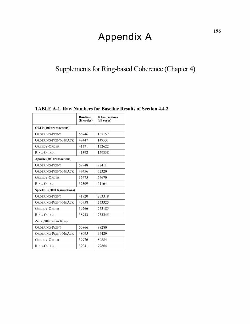
196Appendix A
Supplements for Ring-based Coherence (Chapter 4)
TABLE A-1. Raw Numbers for Baseline Results of Section 4.4.2Runtime (K cycles)
K Instructions(all cores)
OLTP (100 transactions)
ORDERING-POINT 56746 167157
ORDERING-POINT-NOACK 47447 149531
GREEDY-ORDER 41371 152622
RING-ORDER 41392 159838
Apache (200 transactions)
ORDERING-POINT 59948 92411
ORDERING-POINT-NOACK 47456 72320
GREEDY-ORDER 35475 64670
RING-ORDER 32309 61164
SpecJBB (5000 transactions)
ORDERING-POINT 41720 253318
ORDERING-POINT-NOACK 40958 253325
GREEDY-ORDER 39266 253185
RING-ORDER 38943 253245
Zeus (500 transactions)
ORDERING-POINT 50866 98280
ORDERING-POINT-NOACK 48095 94429
GREEDY-ORDER 39976 80884
RING-ORDER 39041 79864
197The following page shows detailed specifications of the ORDERING-POINT, GREEDY-ORDER
and RING-ORDER cache controllers using a table-based technique [121]. We believe this represen-
tation provides clear, concise visual information yet includes sufficient detail (e.g., transient
states) arguably lacking in the traditional, graphical form of state diagrams.
The rows of each table correspond to the states that the cache controller can enter, including
both stable states (e.g. M, O, E, S, I) and transient states (e.g., IS, IM). The columns correspond to
events that cause the cache to take actions and to potentially change the state. Events are usually
the result of receiving a message from the interconnect or processor core. The table entries them-
selves are the atomic actions taken and, if the state changes, the resulting state (denoted with a
slash, e.g., /S indicates the new state is S).
Consider an example from the ORDERING-POINT cache controller specification in Table A-2:
when a core issues a Load to the cache controller in State I, it sends a GETS message and transi-
tions to state IS. Other cache controllers ignore the inactive GETS (denoted by x for don’t care).
The ordering point (not shown) will activate the GETS, and the cache controller in state O will
eventually observe the active GETS, send data, and transition to state S. The requestor will
observe its Own GETS, transition to state ISA. In state ISA, it will eventually receive the data to
complete the Load and transition to stable state O (since this protocol passes ownership on all
requests). The ORDERING-POINT stable states are {M, O, S, I} and all the others are transient. The
{Inactive GETS} and {Inactive GETM} events are shaded to denote the difference with active
request events.
Table A-3 shows the specification of the GREEDY-ORDER cache controller, with stable states
{M, O, E, S, I}. Various Own GET events indicate the result of the combined response that
198follows the request. For example, the {Own GETS (acked, shared)} event indicates that
the request was acknowledged and that there also exists a sharer such that the requestor cannot
enter the exclusive state when clean data is received. The shaded cells indicate retries which can
occur an unbounded number of times.
Table A-4 shows the specification of the RING-ORDER cache controller. The stable states,
{NONE, SOME, SOMEP, ALL} represent the number of tokens held. SOMEP also indicates if
the cache holds a subset of tokens along with the priority token. IMP and IMSOME indicates an
outstanding exclusive request where the requestor holds the priority token or some tokens, respec-
tively. The P and COA states handle token coalescing during replacements of shared data. The
{FurthestDest GETS} and {FurthestDest GETM} events locally generate when the
core finishes a request but needs to send tokens/data on the ring, as described in Section 4.4.3.
We show an explicit forward action because token response messages can be handled by any
requestor with an MSHR allocated, instead of being delivered to a particular processor.
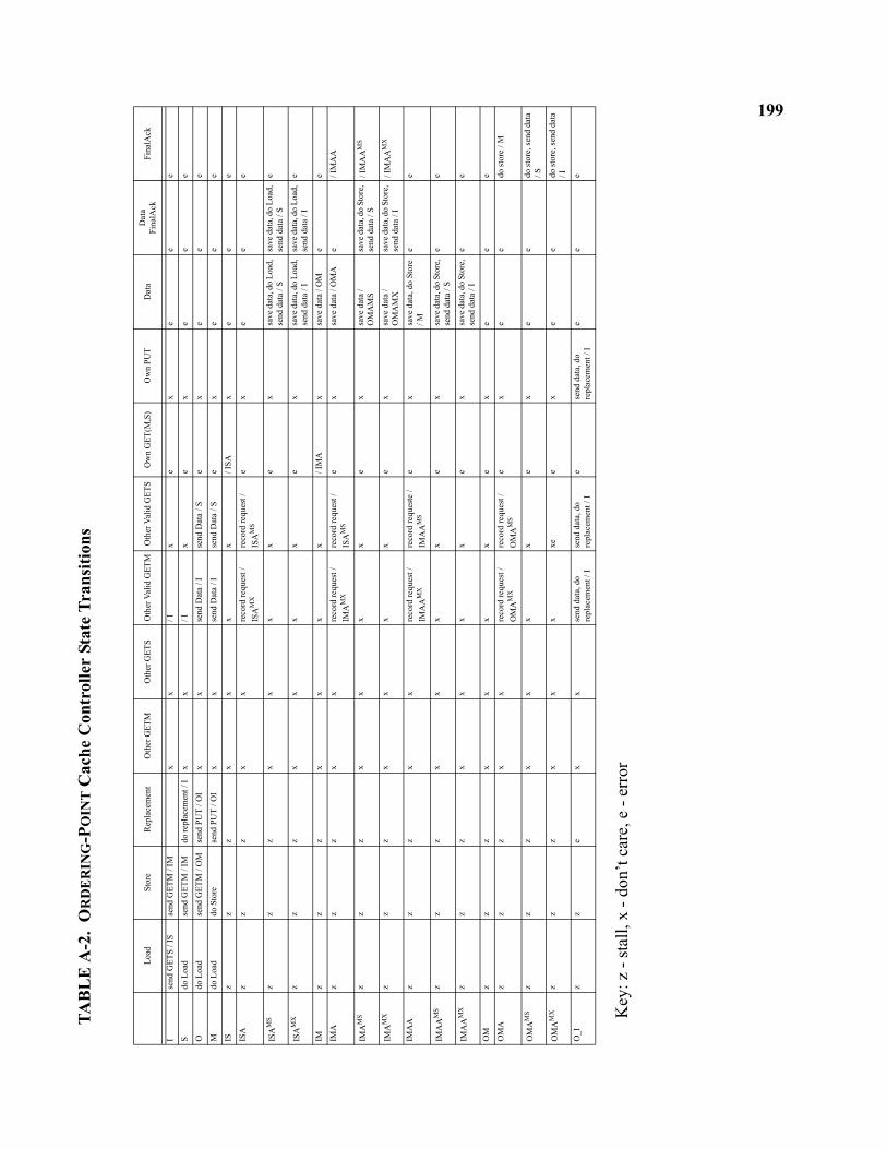
199TA
BL
E A
-2.
OR
DE
RIN
G-P
OIN
T C
ache
Con
trol
ler
Stat
e Tr
ansi
tions
Key
: z -
stal
l, x
- don
’t ca
re, e
- er
ror
Load
Stor
eR
epla
cem
ent
Oth
er G
ETM
Oth
er G
ETS
Oth
er V
alid
GET
MO
ther
Val
id G
ETS
Ow
n G
ET(M
,S)
Ow
n PU
TD
ata
Dat
aFi
nalA
ckFi
nalA
ck
Ise
nd G
ETS
/ IS
send
GET
M /
IMx
x/ I
xe
xe
ee
Sdo
Loa
dse
nd G
ETM
/ IM
do re
plac
emen
t / I
xx
/ Ix
ex
ee
e
Odo
Loa
dse
nd G
ETM
/ O
Mse
nd P
UT
/ OI
xx
send
Dat
a / I
send
Dat
a / S
ex
ee
e
Mdo
Loa
ddo
Sto
rese
nd P
UT
/ OI
xx
send
Dat
a / I
send
Dat
a / S
ex
ee
e
ISz
zz
xx
xx
/ ISA
xe
ee
ISA
zz
zx
xre
cord
requ
est /
IS
AM
Xre
cord
requ
est /
IS
AM
Se
xe
ee
ISA
MS
zz
zx
xx
xe
xsa
ve d
ata,
do
Load
, se
nd d
ata
/ Ssa
ve d
ata,
do
Load
, se
nd d
ata
/ Se
ISA
MX
zz
zx
xx
xe
xsa
ve d
ata,
do
Load
, se
nd d
ata
/ Isa
ve d
ata,
do
Load
, se
nd d
ata
/ Ie
IMz
zz
xx
xx
/ IM
Ax
save
dat
a / O
Me
e
IMA
zz
zx
xre
cord
requ
est /
IM
AM
Xre
cord
requ
est /
IS
AM
Se
xsa
ve d
ata
/ OM
Ae
/ IM
AA
IMA
MS
zz
zx
xx
xe
xsa
ve d
ata
/ O
MA
MS
save
dat
a, d
o St
ore,
se
nd d
ata
/ S/ I
MA
AM
S
IMA
MX
zz
zx
xx
xe
xsa
ve d
ata
/ O
MA
MX
save
dat
a, d
o St
ore,
se
nd d
ata
/ I/ I
MA
AM
X
IMA
Az
zz
xx
reco
rd re
ques
t /
IMA
AM
Xre
cord
requ
este
/ IM
AA
MS
ex
save
dat
a, d
o St
ore
/ Me
e
IMA
AM
Sz
zz
xx
xx
ex
save
dat
a, d
o St
ore,
se
nd d
ata
/ Se
e
IMA
AM
Xz
zz
xx
xx
ex
save
dat
a, d
o St
ore,
se
nd d
ata
/ Ie
e
OM
zz
zx
xx
xe
xe
ee
OM
Az
zz
xx
reco
rd re
ques
t /
OM
AM
Xre
cord
requ
est /
O
MA
MS
ex
ee
do st
ore
/ M
OM
AM
Sz
zz
xx
xx
ex
ee
do st
ore,
send
dat
a / S
OM
AM
Xz
zz
xx
xxe
ex
ee
do st
ore,
send
dat
a / I
O_I
zz
ex
xse
nd d
ata,
do
repl
acem
ent /
Ise
nd d
ata,
do
repl
acem
ent /
Ie
send
dat
a, d
o re
plac
emen
t / I
ee
e
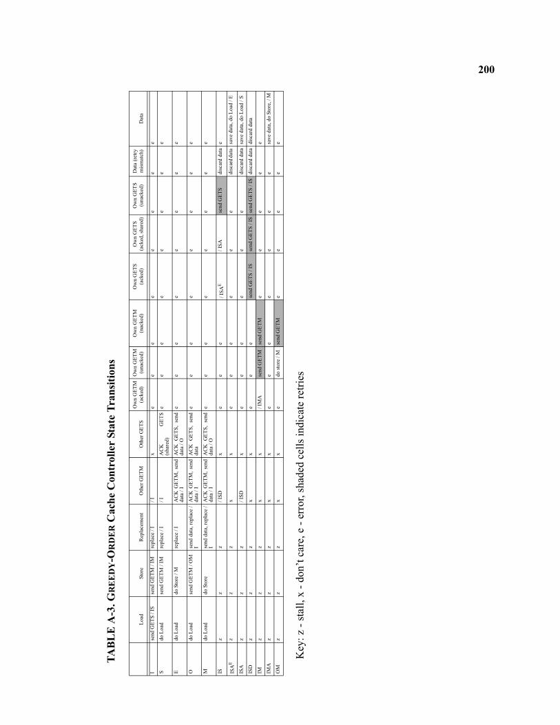
200
TAB
LE
A-3
. GR
EE
DY
-OR
DE
R C
ache
Con
trol
ler
Stat
e Tr
ansi
tions
Key
: z -
stal
l, x
- don
’t ca
re, e
- er
ror,
shad
ed c
ells
indi
cate
retri
es
Load
Stor
eR
epla
cem
ent
Oth
er G
ETM
Oth
er G
ETS
Ow
n G
ETM
(ack
ed)
Ow
n G
ETM
(una
cked
)O
wn
GET
M
(nac
ked)
Ow
n G
ETS
(ack
ed)
Ow
n G
ETS
(ack
ed, s
hare
d)O
wn
GET
S(u
nack
ed)
Dat
a (r
etry
m
ism
atch
)D
ata
Ise
nd G
ETS
/ IS
send
GET
M /
IMre
plac
e / I
/ Ix
ee
ee
ee
ee
Sdo
Loa
dse
nd G
ETM
/ IM
repl
ace
/ I/ I
AC
K
GET
S(s
hare
d)e
ee
ee
ee
e
Edo
Loa
ddo
Sto
re /
Mre
plac
e / I
AC
K G
ETM
, se
ndda
ta /
IA
CK
GET
S, s
end
data
/ O
ee
ee
ee
ee
Odo
Loa
dse
nd G
ETM
/ O
Mse
nd d
ata,
repl
ace
/I
AC
K G
ETM
, se
ndda
ta /
I A
CK
GET
S, s
end
data
ee
ee
ee
ee
Mdo
Loa
ddo
Sto
rese
nd d
ata,
repl
ace
/I
AC
K G
ETM
, se
ndda
ta /
IA
CK
GET
S, s
end
data
/ O
ee
ee
ee
ee
ISz
zz
/ ISD
xe
ee
/ ISA
E/ I
SAse
nd G
ETS
disc
ard
data
e
ISA
Ez
zz
xx
ee
ee
ee
disc
ard d
ata
save
dat
a, d
o Lo
ad /
E
ISA
zz
z/ I
SDx
ee
ee
ee
disc
ard
data
save
dat
a, d
o Lo
ad /
S
ISD
zz
zx
xe
ee
send
GET
S / I
Sse
nd G
ETS
/ IS
send
GET
S / I
Sdi
scar
d da
tadi
scar
d da
ta
IMz
zz
xx
/ IM
Ase
nd G
ETM
send
GET
Me
ee
ee
IMA
zz
zx
xe
ee
ee
ee
save
dat
a, d
o St
ore,
/ M
OM
zz
zx
xe
do st
ore
/ Mse
nd G
ETM
ee
ee
e
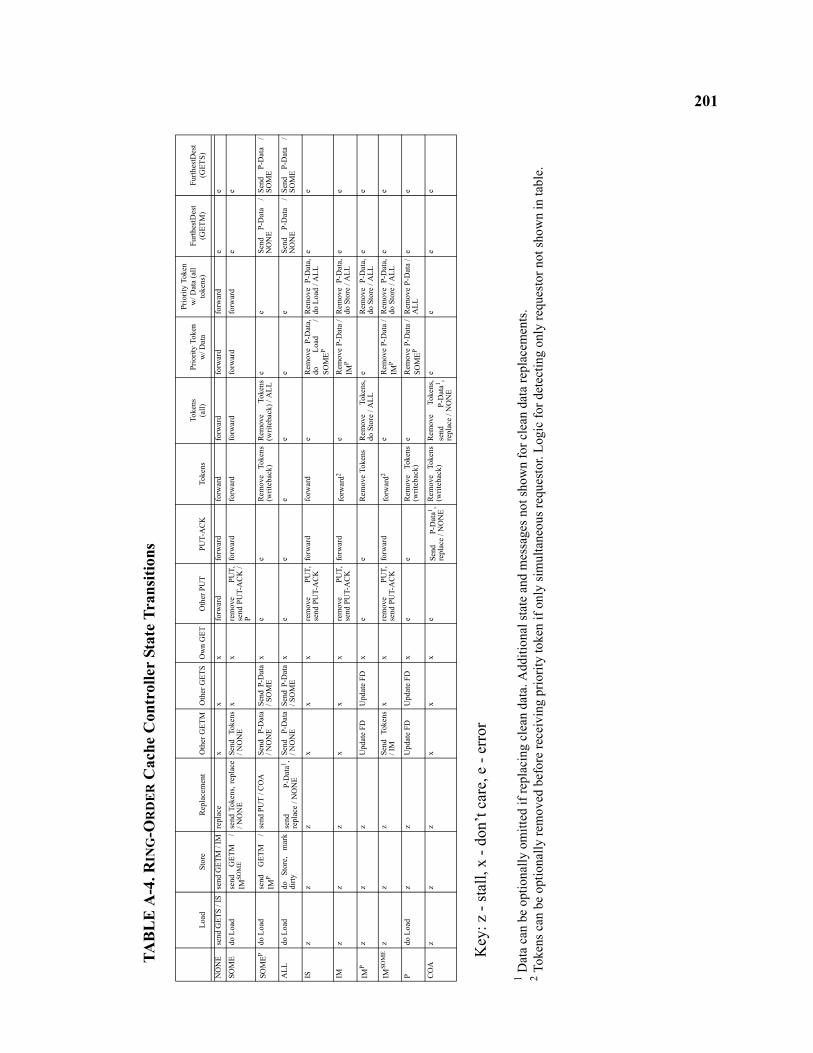
201
TAB
LE
A-4
. RIN
G-O
RD
ER
Cac
he C
ontr
olle
r St
ate
Tran
sitio
ns
Key
: z -
stal
l, x
- don
’t ca
re, e
- er
ror
1 Dat
a ca
n be
opt
iona
lly o
mitt
ed if
repl
acin
g cl
ean
data
. Add
ition
al st
ate
and
mes
sage
s not
show
n fo
r cle
an d
ata
repl
acem
ents
.2 T
oken
s can
be
optio
nally
rem
oved
bef
ore
rece
ivin
g pr
iorit
y to
ken
if on
ly si
mul
tane
ous r
eque
stor
. Log
ic fo
r det
ectin
g on
ly re
ques
tor n
ot sh
own
in ta
ble.
Load
Stor
eR
epla
cem
ent
Oth
er G
ETM
Oth
er G
ETS
Ow
n G
ETO
ther
PU
TPU
T-A
CK
Toke
nsTo
kens
(all)
Prio
rity
Toke
n w
/ Dat
a
Prio
rity
Toke
n w
/ Dat
a (a
ll to
kens
)Fu
rthes
tDes
t (G
ETM
)Fu
rthes
tDes
t (G
ETS)
NO
NE
send
GET
S / I
Sse
nd G
ETM
/ IM
repl
ace
xx
xfo
rwar
dfo
rwar
dfo
rwar
dfo
rwar
dfo
rwar
dfo
rwar
de
e
SOM
Edo
Loa
dse
nd
GET
M
/IM
SOM
Ese
nd T
oken
s, re
plac
e/ N
ON
ESe
nd T
oken
s/ N
ON
Ex
xre
mov
e PU
T,se
nd P
UT-
AC
K /
P
forw
ard
forw
ard
forw
ard
forw
ard
forw
ard
ee
SOM
EPdo
Loa
dse
nd
GET
M
/IM
Pse
nd P
UT
/ CO
ASe
nd
P-D
ata
/ NO
NE
Send
P-D
ata
/ SO
ME
xe
eR
emov
e To
kens
(writ
ebac
k)R
emov
e To
kens
(writ
ebac
k) /
ALL
ee
Send
P-
Dat
a /
NO
NE
Send
P-
Dat
a /
SOM
E
ALL
do L
oad
do
Stor
e,
mar
kdi
rtyse
nd
P-D
ata1 ,
repl
ace
/ NO
NE
Send
P-
Dat
a/ N
ON
ESe
nd P
-Dat
a/ S
OM
Ex
ee
ee
ee
Send
P-
Dat
a /
NO
NE
Send
P-
Dat
a /
SOM
E
ISz
zz
xx
xre
mov
e PU
T,se
nd P
UT-
AC
Kfo
rwar
dfo
rwar
de
Rem
ove
P-D
ata,
do
Load
/
SOM
EP
Rem
ove
P-D
ata,
do L
oad
/ ALL
ee
IMz
zz
xx
xre
mov
e PU
T,se
nd P
UT-
AC
Kfo
rwar
dfo
rwar
d2e
Rem
ove
P-D
ata
/IM
PR
emov
e P-
Dat
a,do
Sto
re /
ALL
ee
IMP
zz
zU
pdat
e FD
Upd
ate
FDx
ee
Rem
ove
Toke
nsR
emov
e To
kens
,do
Sto
re /
ALL
eR
emov
e P-
Dat
a,do
Sto
re /
ALL
ee
IMSO
ME
zz
zSe
nd T
oken
s/ I
Mx
xre
mov
e PU
T,se
nd P
UT-
AC
Kfo
rwar
dfo
rwar
d2e
Rem
ove
P-D
ata
/IM
PR
emov
e P-
Dat
a,do
Sto
re /
ALL
ee
Pdo
Loa
dz
zU
pdat
e FD
Upd
ate
FDx
ee
Rem
ove
Toke
ns(w
riteb
ack)
eR
emov
e P-
Dat
a /
SOM
EPR
emov
e P-
Dat
a /
ALL
ee
CO
Az
zz
xx
xe
Send
P-
Dat
a1 ,re
plac
e / N
ON
ER
emov
e To
kens
(writ
ebac
k)R
emov
e To
kens
,se
nd
P-D
ata1 ,
repl
ace
/ NO
NE
ee
ee
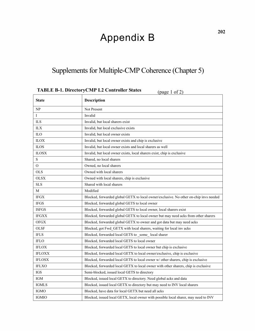
202Appendix B
Supplements for Multiple-CMP Coherence (Chapter 5)
TABLE B-1. DirectoryCMP L2 Controller States
State Description
NP Not Present
I Invalid
ILS Invalid, but local sharers exist
ILX Invalid, but local exclusive exists
ILO Invalid, but local owner exists
ILOX Invalid, but local owner exists and chip is exclusive
ILOS Invalid, but local owner exists and local sharers as well
ILOSX Invalid, but local owner exists, local sharers exist, chip is exclusive
S Shared, no local sharers
O Owned, no local sharers
OLS Owned with local sharers
OLSX Owned with local sharers, chip is exclusive
SLS Shared with local sharers
M Modified
IFGX Blocked, forwarded global GETX to local owner/exclusive. No other on-chip invs needed
IFGS Blocked, forwarded global GETS to local owner
ISFGS Blocked, forwarded global GETS to local owner, local sharers exist
IFGXX Blocked, forwarded global GETX to local owner but may need acks from other sharers
OFGX Blocked, forwarded global GETX to owner and got data but may need acks
OLSF Blocked, got Fwd_GETX with local sharers, waiting for local inv acks
IFLS Blocked, forwarded local GETS to _some_ local sharer
IFLO Blocked, forwarded local GETS to local owner
IFLOX Blocked, forwarded local GETS to local owner but chip is exclusive
IFLOXX Blocked, forwarded local GETX to local owner/exclusive, chip is exclusive
IFLOSX Blocked, forwarded local GETS to local owner w/ other sharers, chip is exclusive
IFLXO Blocked, forwarded local GETX to local owner with other sharers, chip is exclusive
IGS Semi-blocked, issued local GETS to directory
IGM Blocked, issued local GETX to directory. Need global acks and data
IGMLS Blocked, issued local GETX to directory but may need to INV local sharers
IGMO Blocked, have data for local GETX but need all acks
IGMIO Blocked, issued local GETX, local owner with possible local sharer, may need to INV
(page 1 of 2)
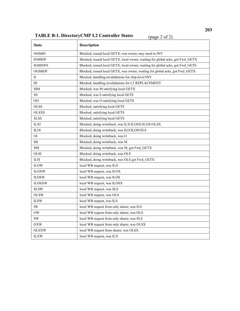
203
OGMIO Blocked, issued local GETX, was owner, may need to INV
IGMIOF Blocked, issued local GETX, local owner, waiting for global acks, got Fwd_GETX
IGMIOFS Blocked, issued local GETX, local owner, waiting for global acks, got Fwd_GETS
OGMIOF Blocked, issued local GETX, was owner, waiting for global acks, got Fwd_GETX
II Blocked, handling invalidations for chip-level INV
III Blocked, handling invalidations for L2 REPLACEMENT
MM Blocked, was M satisfying local GETX
SS Blocked, was S satisfying local GETS
OO Blocked, was O satisfying local GETS
OLSS Blocked, satisfying local GETS
OLSXS Blocked, satisfying local GETS
SLSS Blocked, satisfying local GETS
ILXI Blocked, doing writeback, was ILX/ILOSX/ILOX/OLSX
ILOI Blocked, doing writeback, was ILO/ILOS/OLS
OI Blocked, doing writeback, was O
MI Blocked, doing writeback, was M
MII Blocked, doing writeback, was M, got Fwd_GETX
OLSI Blocked, doing writeback, was OLS
ILSI Blocked, doing writeback, was OLS got Fwd_GETX
ILOW local WB request, was ILO
ILOXW local WB request, was ILOX
ILOSW local WB request, was ILOS
ILOSXW local WB request, was ILOSX
SLSW local WB request, was SLS
OLSW local WB request, was OLS
ILSW local WB request, was ILS
IW local WB request from only sharer, was ILS
OW local WB request from only sharer, was OLS
SW local WB request from only sharer, was SLS
OXW local WB request from only sharer, was OLSX
OLSXW local WB request from sharer, was OLSX
ILXW local WB request, was ILX
TABLE B-1. DirectoryCMP L2 Controller States
State Description
(page 2 of 2)
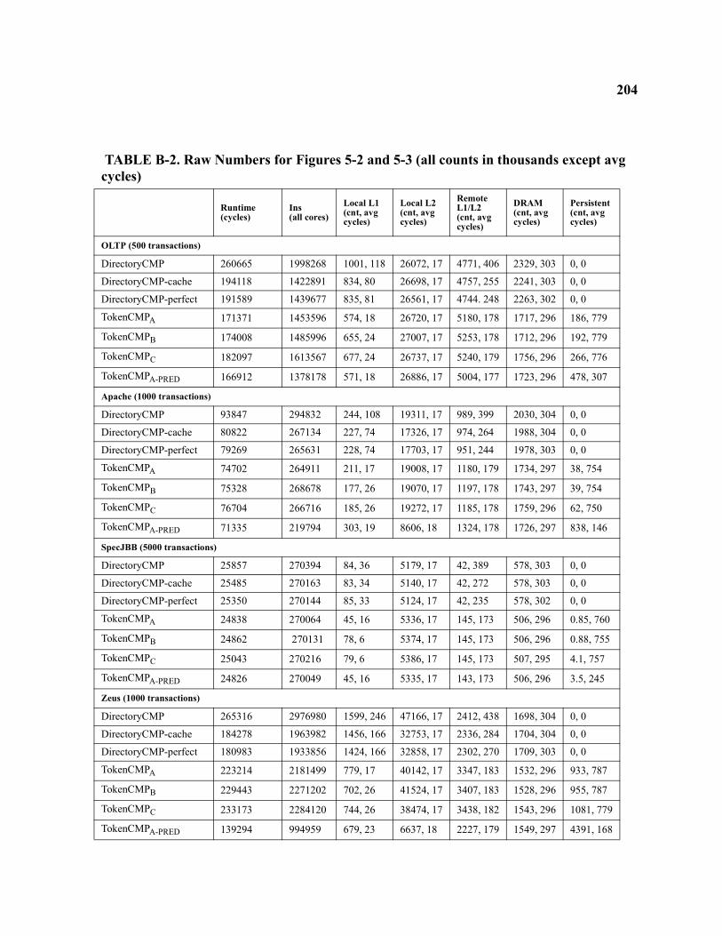
204
TABLE B-2. Raw Numbers for Figures 5-2 and 5-3 (all counts in thousands except avg cycles)
Runtime (cycles)
Ins(all cores)
Local L1(cnt, avg cycles)
Local L2(cnt, avg cycles)
Remote L1/L2(cnt, avg cycles)
DRAM(cnt, avg cycles)
Persistent(cnt, avg cycles)
OLTP (500 transactions)
DirectoryCMP 260665 1998268 1001, 118 26072, 17 4771, 406 2329, 303 0, 0
DirectoryCMP-cache 194118 1422891 834, 80 26698, 17 4757, 255 2241, 303 0, 0
DirectoryCMP-perfect 191589 1439677 835, 81 26561, 17 4744. 248 2263, 302 0, 0
TokenCMPA 171371 1453596 574, 18 26720, 17 5180, 178 1717, 296 186, 779
TokenCMPB 174008 1485996 655, 24 27007, 17 5253, 178 1712, 296 192, 779
TokenCMPC 182097 1613567 677, 24 26737, 17 5240, 179 1756, 296 266, 776
TokenCMPA-PRED 166912 1378178 571, 18 26886, 17 5004, 177 1723, 296 478, 307
Apache (1000 transactions)
DirectoryCMP 93847 294832 244, 108 19311, 17 989, 399 2030, 304 0, 0
DirectoryCMP-cache 80822 267134 227, 74 17326, 17 974, 264 1988, 304 0, 0
DirectoryCMP-perfect 79269 265631 228, 74 17703, 17 951, 244 1978, 303 0, 0
TokenCMPA 74702 264911 211, 17 19008, 17 1180, 179 1734, 297 38, 754
TokenCMPB 75328 268678 177, 26 19070, 17 1197, 178 1743, 297 39, 754
TokenCMPC 76704 266716 185, 26 19272, 17 1185, 178 1759, 296 62, 750
TokenCMPA-PRED 71335 219794 303, 19 8606, 18 1324, 178 1726, 297 838, 146
SpecJBB (5000 transactions)
DirectoryCMP 25857 270394 84, 36 5179, 17 42, 389 578, 303 0, 0
DirectoryCMP-cache 25485 270163 83, 34 5140, 17 42, 272 578, 303 0, 0
DirectoryCMP-perfect 25350 270144 85, 33 5124, 17 42, 235 578, 302 0, 0
TokenCMPA 24838 270064 45, 16 5336, 17 145, 173 506, 296 0.85, 760
TokenCMPB 24862 270131 78, 6 5374, 17 145, 173 506, 296 0.88, 755
TokenCMPC 25043 270216 79, 6 5386, 17 145, 173 507, 295 4.1, 757
TokenCMPA-PRED 24826 270049 45, 16 5335, 17 143, 173 506, 296 3.5, 245
Zeus (1000 transactions)
DirectoryCMP 265316 2976980 1599, 246 47166, 17 2412, 438 1698, 304 0, 0
DirectoryCMP-cache 184278 1963982 1456, 166 32753, 17 2336, 284 1704, 304 0, 0
DirectoryCMP-perfect 180983 1933856 1424, 166 32858, 17 2302, 270 1709, 303 0, 0
TokenCMPA 223214 2181499 779, 17 40142, 17 3347, 183 1532, 296 933, 787
TokenCMPB 229443 2271202 702, 26 41524, 17 3407, 183 1528, 296 955, 787
TokenCMPC 233173 2284120 744, 26 38474, 17 3438, 182 1543, 296 1081, 779
TokenCMPA-PRED 139294 994959 679, 23 6637, 18 2227, 179 1549, 297 4391, 168
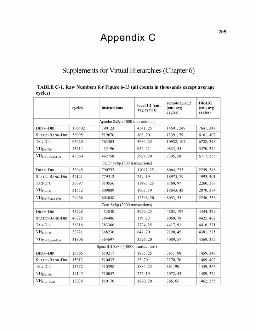
205Appendix C
Supplements for Virtual Hierarchies (Chapter 6)
TABLE C-1. Raw Numbers for Figure 6-13 (all counts in thousands except average cycles)
cycles instructions local L2 (cnt, avg cycles)
remote L1/L2 (cnt, avg cycles)
DRAM (cnt, avg cycles)
Apache 8x8p (1000 transactions)DRAM-DIR 106502 790123 4541, 25 14591, 249 7641, 349STATIC-BANK-DIR 58095 519670 168, 20 12391, 79 6161, 402TAG-DIR 63020 563303 3684, 25 10922, 102 6728, 378VHDir-Dir 43214 435196 952, 21 9833, 45 5570, 374
VHDir-Bcast-Opt 43060 442758 3929, 20 7395, 58 5717, 355
OLTP 8x8p (500 transactions)DRAM-DIR 52045 790753 11097, 25 8064, 233 2259, 348STATIC-BANK-DIR 42121 779312 249, 19 18973, 79 1993, 401TAG-DIR 36797 810556 11895, 25 8360, 97 2260, 376VHDir-Dir 31552 809889 1905, 19 18643, 43 2070, 374
VHDir-Bcast-Opt 29468 803048 12348, 20 8053, 55 2256, 356
Zeus 8x8p (2000 transactions)DRAM-DIR 43728 413840 3929, 25 4803, 197 4444, 349STATIC-BANK-DIR 40725 384486 119, 20 8060, 79 4425, 402TAG-DIR 36316 383366 3724, 25 4417, 91 4416, 371VHDir-Dir 33721 368230 647, 20 7190, 45 4381, 375
VHDir-Bcast-Opt 31806 364697 3526, 20 4089, 57 4369, 355
SpecJBB 8x8p (10000 transactions)DRAM-DIR 13765 510217 1883, 25 361, 198 1459, 348STATIC-BANK-DIR 15913 510437 33, 20 2270, 76 1469, 402TAG-DIR 13572 510398 1884, 25 361, 90 1459, 366VHDir-Dir 14145 510047 225, 19 2072, 43 1489, 374
VHDir-Bcast 13036 510170 1870, 20 365, 65 1462, 355