Embed Size (px)
Citation preview

���������������� ���� ����� ������������� ����� ��������������� ���
� ����������

P.2
P2-2P2-2
Eart
h le
akag
e an
d ov
erlo
ad/s
hort
cir
cuit
pro
tect
ion
syst
ems
wit
h se
lf-r
eclo
sure
Associated breaking element
Page
Earth leakage protection systems with self-reclosure 3-4
Parameters related to self-reclosure relays 5
Protection and earth leakage reclosure 6
REC, built in system Built in 7
WRU-25 RA / WRU-35 RA, Relays with built-in transformer
Contactor
9
RGU-RA / RGU-10 RA / RGU-10C RA, Relays with external transformer 10
WG-35 / WG-70 / WG-105 / WG-140 / WG-210 10
WRU-25 2R / WRU-RM / WRU-RT, other relays with different functions 11
GU72-D RA / CBS-8 12
CBS-8 13
Overload and earth leakage protection / earth leakage reclosure 14
WRKRT-25 T / WRKRT-25 N MCB 15
Overload and earth leakage protection and reclosure
WRU 25 RA-MT, Relays with built-in transformer
MT
17
RGU-10 RA, Relays with external transformer 18
WRT-6-25, other relays with different functions 19
RGMT, other relays with different functions 20
Earth leakage and overvoltage protection / overload and earth leakage reclosure 21
RGST-2 / RGST-4 MT 21
Overload reclosure 22
RRM-P, RRM-C MT 22
Breaking elements
MCB-P / MCB-T circuit breaker 23
MT motorised overload device 24
MT-FDE, MT-FEE motorised overload device 25
Accessories 26
Dimensions / Connection 27-32
CONTENTS
Protección y reconexión diferencial
Protección magnetotérmica y dife-rencial y reconexión diferencial
Protección y reconexión magneto-térmica y diferencial
Reconexión magnetotérmica

P2-3P2-3
Eart
h le
akag
e an
d ov
erlo
ad/s
hort
cir
cuit
pro
tect
ion
syst
ems
wit
h se
lf-r
eclo
sure
P.2
Earth leakage protection systems with self-reclosure
Given the necessity and obligation of ensuring effective protection to both people and goods and the complexity of installations requiring continuous supply of electrical energy without removing earth leakage and overload protection, CIRCUTOR has developed a range of equipment which allows safety to be matched with continuous service. Self-reclosure is the ideal solution for installations requiring continuous supply of electrical energy without the usual maintenance staff:
Rural installationsRefrigerated chambersPublic lightingMobile telephone repeatersTraffi c lightsTunnel lightingATM’sCable televisionetc.
In every self-reclosure system the type of protection to be reconnected and under which conditions must be known.
•••••••••
Self-reclosure systems operate under:
Earth leakage current (differential)Earth leakage current (differential) + overload and short-circuit (overload)
••
TRANSFORMER Signal handling + measuring and trip relay Monitored breaking device
El transformador diferencial detecta la Fuga a tierra. Éste puede estar incorporado en el relé o ser exterior a él.
Elements comprising a self-reclosure system
Self-reclosure relay
Self-reclosure relays offer additional benefi ts (self with closure, overload or short-circuit protection), to the reliability and safety shown by Series U earth leakage protection.
Its functions are:
Fault detection (earth leakage or overload) via a signal generated by the transducerAnalysing if this fault should set off an alarm, with regard to the different preset parametersOperating on a power device which connects – disconnects the load from the system
•••
Differential transformer

P.2
P2-4P2-4
Eart
h le
akag
e an
d ov
erlo
ad/s
hort
cir
cuit
pro
tect
ion
syst
ems
wit
h se
lf-r
eclo
sure
Breaking element
The breaking element always operates as a power switch which supports the line power to be protected and is outside the relay.
The breaking elements which may be associated with self-reclosure relays are:
Motorised overload/short-circuit device (MT series) (see page 24)ContactorCircuit breaker with remote-control (MCB) (see page 23), with the double function of overload/short-circuit protection
and contactor (the conduct of function is bistable)
The features which the breaking elements must know are:
Rated current (in the contactors)Rated currents and the protection thermal curve (in overload/short-circuit devices)Features of the command inputs in the operating elementCut off powerNA or NC auxiliary signalling of the status of the breaking device
•••
•••••
OverloadOverload RRM relay + MT / FDE overload device
Earth leakage
Earth leakage switch reconnector
Differential relay + contactor
Earth leakage
Overload and Earth leakage
Overload and earth leakage
Earth leakage Differential relay + MCB circuit breaker
Differential relay + FDE overload device
Differential relay + MT overload device
Protection Reclosure
Earth leakage + overvoltage Differential relay + MT overload deviceOverload and earth leakage
6
Page
8
14
16
18
21
22

P2-5P2-5
Eart
h le
akag
e an
d ov
erlo
ad/s
hort
cir
cuit
pro
tect
ion
syst
ems
wit
h se
lf-r
eclo
sure
P.2
Parameters related to self-reclosure relays
Indicators associated with protection are different for instant tripping and sealing. Indications are from the same relay (LED) and as an option may be through auxiliary contacts.Another type of display, depending on the relay, is the instant leakage value and the total number of reclosures.
Relay status indication
Typical values:Earth leakage protection 30 mA – 3 AOverload protection 6 A – 63 A.
Rated tripping point for protection
Minimum time which the earth leakage must last to cause the relay to trip.Typical values. 20 ms – 1 s
Timing (delay) for reclosure
This is the time the relay takes from the trip to reclosing.This time may be lineal or exponential.
Time between reclosures
Number of relays with output contact sealing NA or NC
Output relay
The reclosure relays automatically require a permanent auxiliary power supply to be able to manage the automatic connection. Standard value:230 V a.c..± 15 %.Optional 48 V a.c.,110 V a.c., 400 V a.c..
Relay power supply and tolerance
Each relay allows a maximum number of the closures before being sealed. This meter may automatically put on zero if the number maximum number of reclosures has not been exceeded during a preset time (return to zero a time for the reclosure meters).This number will be different for the type of reclosure.
Number of different reclosures / Number of types of reclosure
In order to avoid tripping being mounted up which do not belong to the same fault, a return to zero time for the reclosure meter may be set. This time restarts after each reclosure whenever a maximum number of reclosures is not exceeded.Example: The WRU 25 RA relay has a maximum number of six reclosures before being sealed.
In an installation where the transient earth leakage fault lasts for 50 s, the relay will trip 4 times and reclose 3 times (8 s + 16 s + 30 s). While the third reclosure is being timed the fault disappears so the relay stays on ON. At this time the meter returns to zero reconnections. The RESET option restarts the relay returning the reclosure meters to zero.
Return to zero time for the reclosure meters
The automatic earth leakage reclosure relays offer the same benefi ts as the U series earth leakage protection, among which is the option to check the proper operation of the relay using on-site TEST and RESET using the keypad on the relay itself and remotely using the specifi c inputs.The test is interpreted by the relay as an external leak. The relay will reconnect after a given time and increase the internal reclosure meter. The reset option restarts and relay return in the reclosure meters to zero.
On site and remote Test and Reset (using the keypad)

P.2
P2-6P2-6
Eart
h le
akag
e an
d ov
erlo
ad/s
hort
cir
cuit
pro
tect
ion
syst
ems
wit
h se
lf-r
eclo
sure
In the majority of cases (95 %), when the earth leakage protection is tripped, a simple manual reconnection solves the problem because there is no permanent leakage.
If there is no REC automatic reconnector, this simple, manual reconnection operation may become a serious problem if there is nobody nearby or if the earth leakage trip is not known:
• Food rots in the fridge• Plants wither through lack of watering• Swimminutesg pool water goes bad• The alarm system does not protect• The tilting garage door does not work• The farm may suffer serious damage• There is no mobile telephone coverage (fault with t h e telephone repeater)• The ATM does not work• Streets and squares remain in the dark• Traffi c lights stop working• etc.
Pure earth leakage switch with automatic resetting
Hole for padlockOption for manual locking with padlock
Manual switch (yellow lever):position I: automatic operationposition 0: self-reclosure not permitted
Terminals for the command line:N - L: 230 V AC power supplyLI: external reclosure order (optional)
Free of power output indicates in earth leakage status
Number of reclosures Time between reclosures
6 20, 30, 60, 120, 600 s
The reclosure metre returns to zero if:• Leakage is not permanent• It always reconnects manually
Ear
th le
akag
e
Motor
2 or 4 pole breaking element
Earth leakage protection required by current legislation protects people but unforeseen that trips made provoke a fault with the electrical supply in important installations.
REC from CIRCUTOR is safe, easy to install, economic or will guarantee self-reclosure in your installation whenever the leakage is not permanent.
PROTECTION AND EARTH LEAKAGE RECLOSURE
AUTOMATIC EARTH LEAKAGE RECONNECTOR SWITCH - REC

P2-7P2-7
Eart
h le
akag
e an
d ov
erlo
ad/s
hort
cir
cuit
pro
tect
ion
syst
ems
wit
h se
lf-r
eclo
sure
P.2
On request Class A
REC
Earth leakage protection
Class Electromechanical AC or A, according to type
Measuring Instant value
Sensitivity I∆n 30 mA or 300 mA (according to type)
Delay Fixed at 20 ms
Diferential transformer Built in
Test Via built in button
Reset Manual, by lifting the lever
Asociated breaking element Built in
In and number of poles In 40 A or 63 A , 2 or 4 poles
Breaking element control Electromechanical relay
REC 2 Poles
REC 4 Poles
Poles Class I n (A) Sensitivity Type Code
2 AC 40 30 mA REC 2-40-30 P241112 AC 40 300 mA REC 2-40-300 P241212 AC 63 30 mA REC 2-63-30 P241142 AC 63 300 mA REC 2-63-300 P241244 AC 40 30 mA REC 4-40-30 P241124 AC 40 300 mA REC 4-40-300 P241224 AC 63 30 mA REC 4-63-30 P24113
4 AC 63 300 mA REC 4-63-300 P24123
Earth leakage reclosure
Number of reclosures 6
Time between reclosures 10, 20, 30, 60, 120, 600 s
Return to zero time for partial meter
Same as last time between reclosures (For example: fi nal reclosure on the third
attempt → return to the zero time after 30 s)
Safety seal Using disconnection lever
Remote signalling (outputs) Voltage free switched relay for status indication
Remote-control (inputs) External reset using button
Protection Reclosure
2 poles 4 poles
Electrical features
Auxiliary power supply 230 / 400 V a.c., 50...60 Hz
Outputs contacts 2 A maximum for 250 V a.c. / 24 V d.c.
Operating temperature -25 ºC / + 55 ºC
Assembly features
Mounting DIN rail
Dimensions 5 modules (90 x 90 mm) 7 modules (125 x 90 mm)
Weight 560 g 693 g
Protection grade IP 40
Standards IEC 61008-1, IEC 755, IEC 255-5
Features

P.2
P2-8P2-8
Eart
h le
akag
e an
d ov
erlo
ad/s
hort
cir
cuit
pro
tect
ion
syst
ems
wit
h se
lf-r
eclo
sure
Switch formed by:Earth leakage relay + contactor
Settable sensitivityLeakage current level indicator via variable fl ashing
Earth leakage protection + earth leakage reclosure
APPLICATIONS
Traffi c lightsCar parksRefrigerated chambers
•••
Number of poles and line current defi ned by the contactor
Settable delayClass A insulated.High-frequency fi ltering
Street lighting Offi ce blocks
PROTECTION AND EARTH LEAKAGE RECLOSURE
INSULATED SWITCH WITH SETTABLE SENSITIVITY AND DELAY

P2-9P2-9
Eart
h le
akag
e an
d ov
erlo
ad/s
hort
cir
cuit
pro
tect
ion
syst
ems
wit
h se
lf-r
eclo
sure
P.2
WRU 25 RA WRU 35 RA
Earth leakage protection
Class A superinsulated
Measuring TRMS
Sensitivity I∆n Selectable 30 mA...3 A
Delay Selectable 20 ms ... 1s
Differential transformer Built in ∅ 25 mm Built in ∅ 35 mm
Test y Reset Via built in button
Associated breaking element Contactor
In and number of poles Defi ned by contactor used
Breaking element control 1 switched relay
WRU 25 RA WRU 35 RA
Electrical features
Auxiliary power supply 230 V a.c. (± 20 %) 50...60 Hz
Breaking element control contacts 250 V a.c. / 8 A a.c.
Operating temperature - 10 ºC / + 50 ºC
Mechanical features
Mounting DIN rail
Dimensions 4 modules 6 modules
Weight 234 g 415 g
Protection grade Terminals: IP20, Built in relay: IP41
Standards IEC 61008-1, IEC 755, IEC 255-5
WRU 25 RA WRU 35 RA
Earth leakage reclosure
No. of reclosures 6
Time between reclosures 8, 16, 30, 59, 115, 224 s
Return to zero time for partial meter 15 minutes
Signalling in the relay
LED
– Presence of voltage indicator– Sealed reclosure– Indicates the presence of leakage current without reaching the trip point
Remote signalling (outputs)
Leakage control signal (proportional alternating voltage)
Remote-control (inputs) External test using button
Protection Reclosure
Features
Earth leakage relay with built in transformer
+WRU-35 RA
WRU-25 RA
Class In (A) PolesUseful
diameter ∅ mm
I∆n or Sensitivity (A) Delay (s) Type Code
A 63 (*) 2, 3, 4 25 0,03...3 0,02...1 WRU-25 RA P24211
A 125 (*) 2, 3, 4 35 0,03...3 0,02...1 WRU-35 RA P24221
(*) According to contactor
Complete set formed by:Earth leakage relay + Contactor
Type Number of reclosures
Time between reclosures (s)
WRU-25 RA 6 8,16,30,59,115,224
WRU-35 RA 6 8,16,30,59,115,224

P.2
P2-10P2-10
Eart
h le
akag
e an
d ov
erlo
ad/s
hort
cir
cuit
pro
tect
ion
syst
ems
wit
h se
lf-r
eclo
sure
RGU-RA RGU-10 RA
Earth leakage protection
Class A superinsulated
Measuring TRMS
Sensitivity I∆n Selectable 30 mA...3 A Programmable 30 mA...30 A
Delay Selectable 20 ms ... 1s Programmable 20 ms ... 1s
Inverse curve: Instant or selective
Differential transformer External, Serie WG
Test y Reset Via built in button
Associated breaking element
Contactor
In and number of poles Defi ned by contactor used
Breaking element control 1 switched relay 1 relay simple
Protection
RGU-RA RGU-10 RA
Earth leakage reclosure
Number of reclosures 6 Programmable: 0... 10
Time between reclosures 8, 16, 30, 59, 115, 224 s Programmable: 1... 900 s
Return to zero time for partial meter
15 minutes 15 / 30 minutes
Signalling in the relay
LED
- Presence of voltage- Sealed reclosure- Indicates the presence of leakage current without reaching the trip point
- Presence of voltage - One channel tripped - Reclosure enabled - Sealed status - RS-485 Communications
Display - LCD
Remote signalling (outputs) - Prealarm relay
Remote-control (inputs) - ON / OFF
Reclosure
RGU-RA RGU-10 RA
Electrical features
Auxiliary power supply 230 V a.c. (± 20 %) 50...60 Hz
Breaking element control contacts 250 V a.c. / 8 A.a.c 250 V a.c. / 6 A a.c.
Operating temperature -10 ºC / +50 ºC
Mechanical features
Mounting DIN rail
Dimensions 4 modules 3 modules
Weight 261 g 236 g
Protection grade Terminals: IP20, Built in relay: IP41
Standards IEC 61008-1, IEC 755, IEC 255-5
Features
Earth leakage relay with external transformer
+
I∆n (A)
Delay(s) Communications Number of
reclosures Breaking element control Remote signalling Type Code
0,03...3 0,02...1 - 6 Switched relay - RGU-RA P24311
0,03...30 0,02...10 - Programmable NA relay-Positive safety Relay seal RGU-10 RA P24612
0,03...30 0,02...10 RS-485 Programmable NA relay-Positive safety - RGU-10C RA P24632
Useful diameter (mm) Type Code
30 ∅ WG-35 P10111
70 ∅ WG-70 P10112
105 ∅ WG-105 P10113
140 ∅ WG-140 P10114
210 ∅ WG-210 P10115
Selection of differential transformer according to rated line current
Complete set formed by:Earth leakage relay + Toroidal transformer + Contactor RGU-10-RA
RGU-RA +

P2-11P2-11
Eart
h le
akag
e an
d ov
erlo
ad/s
hort
cir
cuit
pro
tect
ion
syst
ems
wit
h se
lf-r
eclo
sure
P.2
WRU-25-2R WRU-RM WRU-RT
Earth leakage protection
Class A superinsulated
Measuring TRMS
Sensitivity I∆n Settable 300 mA ... 1 A Selectable 30 mA ... 3 A
Delay Fixed 20 ms Selectable 20 ms ... 1 s
Differential transformer Built in Ø 25 mm
Test y Reset Via built in button
Associated breaking element Contactor
In and number of poles Defi ned by contactor used
WRU-25-2R WRU-RM WRU-RT
Electrical features
Auxiliary power supply 230 V a.c. (± 20%) 50...60 Hz
Breaking element control contacts 250 V a.c. / 8 V a.c.
Operating temperature -10 ºC / +50 ºC
Mechanical features
Mounting DIN rail
Dimensions 4 modules
Weight 234 g
Protection grade Terminals: IP20, Built in relay: IP41
Standards IEC 61008-1, IEC 755, IEC 255-5
Features
WRU-25-2R WRU-RM WRU-RT
Earth leakage reclosure
Number of reclosures 31 30
Time between reclosures 1st at 2 min., 2nd at 4 min., remainder every 6 min. 20 s, 40 s y las 28 remainder every 5 minutes
Return to zero time for partial meter 15 minutes 15 minutes
Reclosure
Protection
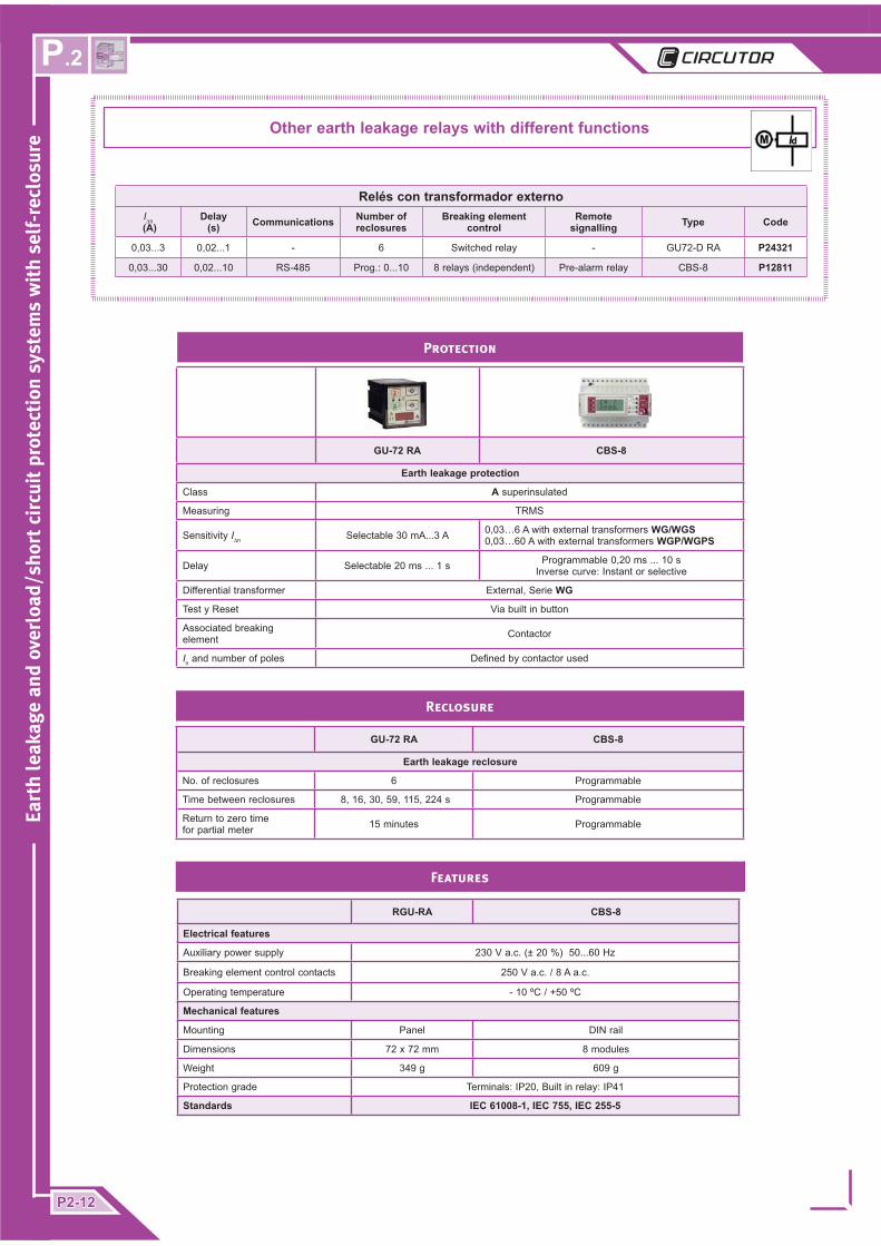
Other earth leakage relays with different functions
Relays with built in transformerUseful
diameter ∅ mm
I∆n (A)
Delay(s)
Number of reclosures
Breaking element control
Remote signalling Type Code
25 0,03...3 0,02...1 30 Switched relay - WRU-RM P24231
25 0,03...3 0,02...1 3 1 NA-SP contact 1 NA-SP contact WRU-RT P24431
25 0,3...1 0,02 3 1 NC contact 1 NA contact WRU-25-2R P24412
P.2
P2-12P2-12
Eart
h le
akag
e an
d ov
erlo
ad/s
hort
cir
cuit
pro
tect
ion
syst
ems
wit
h se
lf-r
eclo
sure
GU-72 RA CBS-8
Earth leakage protection
Class A superinsulated
Measuring TRMS
Sensitivity I∆n Selectable 30 mA...3 A 0,03…6 A with external transformers WG/WGS0,03…60 A with external transformers WGP/WGPS
Delay Selectable 20 ms ... 1 s Programmable 0,20 ms ... 10 s Inverse curve: Instant or selective
Differential transformer External, Serie WG
Test y Reset Via built in button
Associated breaking element Contactor
In and number of poles Defi ned by contactor used
RGU-RA CBS-8
Electrical features
Auxiliary power supply 230 V a.c. (± 20 %) 50...60 Hz
Breaking element control contacts 250 V a.c. / 8 A a.c.
Operating temperature - 10 ºC / +50 ºC
Mechanical features
Mounting Panel DIN rail
Dimensions 72 x 72 mm 8 modules
Weight 349 g 609 g
Protection grade Terminals: IP20, Built in relay: IP41
Standards IEC 61008-1, IEC 755, IEC 255-5
Features
GU-72 RA CBS-8
Earth leakage reclosure
No. of reclosures 6 Programmable
Time between reclosures 8, 16, 30, 59, 115, 224 s Programmable
Return to zero time for partial meter 15 minutes Programmable
Reclosure
Protection
Other earth leakage relays with different functions
Relés con transformador externoI∆n
(A)Delay
(s) Communications Number of reclosures
Breaking element control
Remote signalling Type Code
0,03...3 0,02...1 - 6 Switched relay - GU72-D RA P24321
0,03...30 0,02...10 RS-485 Prog.: 0...10 8 relays (independent) Pre-alarm relay CBS-8 P12811

P2-13P2-13
Eart
h le
akag
e an
d ov
erlo
ad/s
hort
cir
cuit
pro
tect
ion
syst
ems
wit
h se
lf-r
eclo
sure
P.2
Accessories
CBS-8
8 earth leakage protection programmable relays, class A Frequency fi lteringDisconnection delay using inverse curveIndependent programminutesg per channel
••••
Reduction of unforeseen trips
Increases the continuity of the production
process
Smaller size
2 signalling LEDs:- ON / Fault trip- Pre-alarm / Reclosure status
Signalling LED
- Instant leakage current- Leakage current trip
Displays in TRMS
Test and reset buttons
Test and reset buttons
With the associated breaking element to carry out earth leakage protection
Connection indicator
Setting using rotating parameter menu. 4 buttons
Programmable
- Sensitivity- Delay- Channel to be set
Parameter display
Option for RS485 Communications. MODBUS Protocol. Only displays programminutesg parameters, leakage values and status of each channel.
Communications
TT(see page 26)
WG and WGP differential
transformers

P.2
P2-14P2-14
Eart
h le
akag
e an
d ov
erlo
ad/s
hort
cir
cuit
pro
tect
ion
syst
ems
wit
h se
lf-r
eclo
sure
Switch formed by:Earth leakage relay + circuit breaker
Settable sensitivity
Leakage current level indicator via variable fl ashing
Overload and earth leakage protection + earth leakage reclosure
Applications
Number of poles and line current defi ned by the contactor
+
Settable delay
Class A insulated.High-frequency fi ltering
Street lighting Telephone systems
Relay input:WRKRT-25 T : for resettingWRKRT-25 N : for remote control
Traffi c lightsCable TV
••
Overload and earth leakage protection / Earth leakage reclosure
INSULATED RELAY WITH SETTABLE SENSITIVITY AND DELAY

P2-15P2-15
Eart
h le
akag
e an
d ov
erlo
ad/s
hort
cir
cuit
pro
tect
ion
syst
ems
wit
h se
lf-r
eclo
sure
P.2
Accessories
Circuit breaker MCB (page 23)
WRKRT-25 T WRKRT-25 N
Earth leakage and overload protection
Class A Superinsulated
Measuring TRMS
Sensitivity Selectable 30 mA ... 3 A
Delay Selectable 20 ms ... 1 s
Differential transformer Built in ∅ 25 mmTest y Reset Via built in button
Associated breaking element MCB.T circuit breaker MCB.P circuit breaker
Number of poles , In, thermal curve, cut off power Defi ned by circuit breaker used
WRKRT-25 T / WRKRT-25 N
Electrical features
Auxiliary power supply 230 V a.c. (±20 %) 50...60 Hz
Breaking element control contacts Maximum current 3 A a.c.
Operating temperature -10 ºC / +50 ºC
Features
WRKRT-25 T WRKRT-25 N
Earth leakage reclosure
Number of reclosures 30 6
Time between reclosures 20 s, 40 s, los 28 remainder every 5 minutes.
Return to zero time for partial meter 15 minutes
Signalling in the relay
LED
- Presence of voltage indicator- Sealed reclosure
- Indicates the presence of leakage current without reaching the trip point
Remote-control (inputs) External reset using button
Inputs ON (earth leakage only) and relay OFF
Protection Reclosure
WRKRT-25 T / WRKRT-25 N
Mechanical features
Mounting DIN rail
Dimensions 4 modules
Weight 235 g
Protection grade Terminals: IP20, Built in relay: IP41
Standards IEC 61008-1, IEC 755, IEC 255-5, IEC 947-2
Earth leakage relay with built in transformer
PolesUseful
diameter∅ mm
In (A) Delay (s) Type Code
Up to 63 A 2, 3+N 25 0,03...3 0,02...1 WRKRT-25 T P23111
Up to 63 A 2, 3+N 25 0,03...3 0,02...1 WRKRT-25 N P23121
With sensitivity adjustment on 0.03 A, delay cancelled
Complete set formed by:Earth leakage relay + MCB circuit breaker (suitable for the line)

P.2
P2-16P2-16
Eart
h le
akag
e an
d ov
erlo
ad/s
hort
cir
cuit
pro
tect
ion
syst
ems
wit
h se
lf-r
eclo
sure
Switch formed by:Earth leakage + overload relay
Settable sensitivity
Leakage current level indicator via variable fl ashing
Overload and earth leakage protection +Overload and earth leakage reclosure
APPLICATIONS
Number of poles and line current defi ned by the contactor
+
Settable delay
Class A insulated.High-frequency fi ltering
Street lighting Offi ce blocks
OVERLOAD AND EARTH LEAKAGE PROTECTION AND RECLOSURE
INSULATED RELAY WITH SETTABLE SENSITIVITY AND DELAY

P2-17P2-17
Eart
h le
akag
e an
d ov
erlo
ad/s
hort
cir
cuit
pro
tect
ion
syst
ems
wit
h se
lf-r
eclo
sure
P.2
WRU-25 RA-MT
Earth leakage protection
Class A superinsulated
Measuring TRMS
Sensitivity I∆n Selectable 30 mA...3 A
Delay Selectable 20 ms ... 1 s
Differential transformer Built in ∅ 25 mm
Test y Reset Via built in button
Associated breaking element Overload device Serie MT
Rated In thermal curve, cut off power and no. of poles
Defi ned by overload device used
Breaking element control 1 switched relay
WRU-RA-MT
Electrical features
Auxiliary power supply 230 V a.c. (±15 %) 50...60 Hz
Breaking element control contacts 250 V a.c. / 8 A a.c.
Output contacts Maximum current 3 A
Operating temperature -10 ºC / +50 ºC
Assembly features
Mounting DIN rail
Dimensions 4 modules
Weight 234 g
Protection grade Terminals: IP20, Built in relay: IP41
Standards IEC 61008-1, IEC 755, IEC 255-5
WRU-25 RA-MT
Earth leakage and overload reclosure
Number of reclosures 6
Time between reclosures 8, 16, 30, 59, 115, 224 s
Return to zero time for partial meter 15 minutes
Safety sealing In the overload device. Using disconnection lever.
Signalling in the relay
LED - Presence of voltage indicator- And/or earth fault indicator
Remote signalling (outputs) Leakage control signal (proportional alternating voltage)
Protection Reclosure
Features
Accessories
MT overload decive (page. 24)
Earth leakage relay with built in transformer
Complete set formed by:Earth leakage relay + MT overload device
In Poles Sensitivity Type Code
Up to 63 A 2 , 4 30 mA WRU-25 RA-MT P24241
Type Number of reclosures
Time between reclosures
WRU-25 RA-MT 6 1 minutes

P.2
P2-18P2-18
Eart
h le
akag
e an
d ov
erlo
ad/s
hort
cir
cuit
pro
tect
ion
syst
ems
wit
h se
lf-r
eclo
sure
Features
Protection Reclosure
Earth leakage and overload protection
Class A superinsulated
Measuring TRMS
Sensitivity I∆n Programmable 30 mA...30 A
Delay Programmable 20 ms ... 1 s Inverse curve: Instant or selective
Differential transformer External, Serie WG
Test y Reset Via built in button
Associated breaking element Overload device Serie MT, MT-FDE
In and number of poles Defi ned by overload device used
Breaking element control 1 relay simple
Earth leakage and overload reclosure
No. of reclosures Programmable: 0... 10
Time between reclosures Programmable: 1... 900 s
Return to zero time for partial meter 15 / 30 minutes
Signalling in the relay
LED
- Presence of voltage- A channel has tripped-
- Reclosure enabled- Sealed status
- RS-485 Communications
Display LCD
Remote signalling (outputs) Prealarm relay
Remote-control (inputs) ON / OFF
Electrical features
Auxiliary power supply 230 V a.c. (± 20 %) 50...60 Hz
Breaking element control contacts 5 A a.c. current
Operating temperature -10 ºC / +50 ºC
Mechanical features
Mounting DIN rail
Dimensions 3 modules
Weight 236 g
Protection grade Terminals: IP20, Built in relay: IP41
Standards IEC 61008-1, IEC 755, IEC 255-5
Accessories
MT overload device(page 24)
Earth leakage relay with external transformer
Complete set formed by:Earth leakage relay + WG toroidal+ MT / MT-FDE overload device
Class In (A) Poles Toroidal Delay (s) Type Code
A According to contactor 2 , 3 , 4 Serie WG 0,02...1 RGU-10 RA P24612
Type Number of reclosures Time between reclosures
RGU-10 RA Programmable Programmable
MT overload device(page 25)
P2-19P2-19
Eart
h le
akag
e an
d ov
erlo
ad/s
hort
cir
cuit
pro
tect
ion
syst
ems
wit
h se
lf-r
eclo
sure
P.2
Electrical features
Auxiliary power supply 230 V a.c. (±15 %) 50...60 Hz
Breaking element control contacts 250 V a.c. / 8 A a.c.
Output contacts 250 V a.c. / 8 A a.c.
Operating temperature -10 ºC / +50 ºC
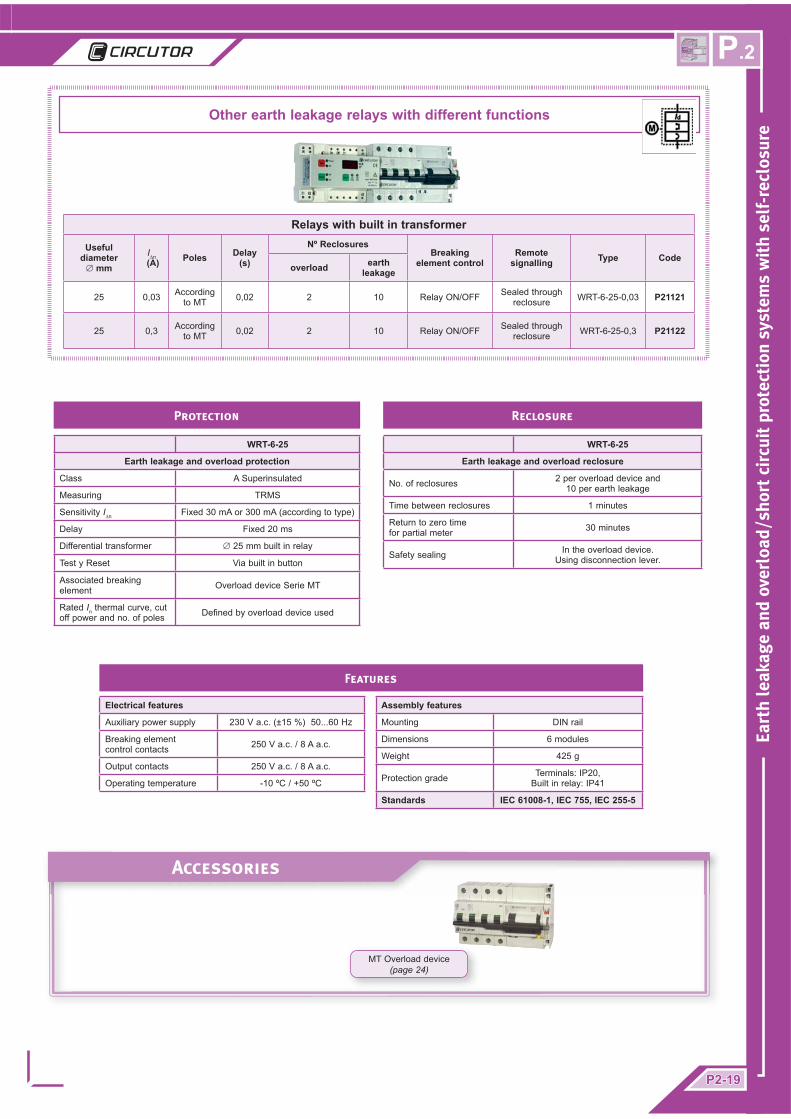
WRT-6-25
Earth leakage and overload protection
Class A Superinsulated
Measuring TRMS
Sensitivity I∆n Fixed 30 mA or 300 mA (according to type)
Delay Fixed 20 ms
Differential transformer ∅ 25 mm built in relay
Test y Reset Via built in button
Associated breaking element Overload device Serie MT
Rated In thermal curve, cut off power and no. of poles Defi ned by overload device used
WRT-6-25
Earth leakage and overload reclosure
No. of reclosures 2 per overload device and 10 per earth leakage
Time between reclosures 1 minutes
Return to zero time for partial meter 30 minutes
Safety sealing In the overload device. Using disconnection lever.
Assembly features
Mounting DIN rail
Dimensions 6 modules
Weight 425 g
Protection grade Terminals: IP20, Built in relay: IP41
Standards IEC 61008-1, IEC 755, IEC 255-5
Features
Protection Reclosure
Accessories
MT Overload device (page 24)
Other earth leakage relays with different functions
Relays with built in transformer
Useful diameter
∅ mmI∆n
(A) Poles Delay(s)
Nº ReclosuresBreaking
element controlRemote
signalling Type Codeoverload earth
leakage
25 0,03 According to MT 0,02 2 10 Relay ON/OFF Sealed through
reclosure WRT-6-25-0,03 P21121
25 0,3 According to MT 0,02 2 10 Relay ON/OFF Sealed through
reclosure WRT-6-25-0,3 P21122

P.2
P2-20P2-20
Eart
h le
akag
e an
d ov
erlo
ad/s
hort
cir
cuit
pro
tect
ion
syst
ems
wit
h se
lf-r
eclo
sure
2 Poles
Type Code
WRGMT-C-2-6 A P21210
WRGMT-C-2-10 A P21211
WRGMT-C-2-16 A P21212
WRGMT-C-2-20 A P21213
WRGMT-C-2-25 A P21214
WRGMT-C-2-32 A P21215
WRGMT-C-2-40 A P21216
WRGMT-C-2-50 A P21217
WRGMT-C-2-63 A P21218
4 Poles
Type Code
WRGMT-C-4-10 A P21221
WRGMT-C-4-16 A P21222
WRGMT-C-4-20 A P21223
WRGMT-C-4-25 A P21224
WRGMT-C-4-32 A P21225
WRGMT-C-4-40 A P21226
WRGMT-C-4-50 A P21227
WRGMT-C-4-63 A P21228
The equipment is formed by:
• RGMT earth leakage relay
• MT ser ies of motor ised overload device or MT-FDE series motorised overload switch with overload protection function and breaking element
• W G s e r i e s d i f f e r e n t i a l transformer
Complete Kits
Other earth leakage relays with different functions
Relays with external transformers
Useful diameter
∅ mmI∆n
(A) Poles Delay(s)
Number of reclosuresBreaking
element controlRemote
signalling Type CodeOverload earth
leakage
According to WG 0,03 / 0,3 According
to MT 0,02 2 10 Relay ON / OFF 2 RGMT P21130
Protection
Class A Superinsulated
Measuring TRMS
Sensitivity I∆n 0,03 / 0,3 A
Delay Fixed 20 ms
Differential transformer External, Serie WG
Test y Reset Via built in button
Associated breaking element Overload device Serie MT
Rated In thermal curve, cut off power and no. of poles Defi ned by overload device used
Earth leakage and overload reclosure
Number of reclosures 2 per overload device and 10 per earth leakage
Time between reclosures 3 minutes
Return to zero time for partial meter 30 minutes
Safety sealing In the overload device. Using disconnection lever.
Electrical features
Auxiliary power supply 230 V a.c. (±15 %) 50...60 Hz
Breaking element control contacts 250 V a.c. / 8 A a.c.
Output contacts 250 V a.c. / 8 A a.c.
Operating temperature -10 ºC / +50 ºC
Assembly features
Mounting DIN rail
Dimensions 6 modules
Weight 350 g
Protection grade Front: IP54, casing and terminals: IP20
Standards IEC 61008-1, IEC 755, IEC 255-5, IEC 947-2, IEC 60898
Features
Protection Reclosure

P2-21P2-21
Eart
h le
akag
e an
d ov
erlo
ad/s
hort
cir
cuit
pro
tect
ion
syst
ems
wit
h se
lf-r
eclo
sure
P.2
Earth leakage, overload and overvoltage protection
Maximum voltage Programmable 235...270 V a.c.
Minimum voltage Programmable 180...210 V a.c.
Conection delay Programmable 100...980 ms (only for overvoltages)
Class A Superinsulated
Measuring TRMS
Sensitivity I∆n Programmable: 30...500 mA
Delay Fixed 20 ms
Differential transformer External Serie WG
Test y Reset Via built in button
Associated breaking element MT series motorised overload device + F6 coil
No. of poles, In, thermal curve, cut off power Defi ned by overload device used
Breaking element control
Using relay (3 relays) ON / OFF and F6 coil. The overload device
disconnection is guaranteed in the event of an auxiliary power supply failure
Electrical features
Auxiliary power supply 230 V a.c. (±15 %) 50...60 Hz
Operating temperature -10 ºC / +50 ºC
Assembly features
Mounting DIN rail
Dimensions 8 modules
Weight 565 g
Protection grade Front: IP54, Casing: IP20, Terminals: IP20
Standards IEC 61008-1, IEC 755, IEC 255-5, IEC 947-2, IEC 60898
Earth leakage and overload reclosure
No. of programmable reclosures
0...3 per overload device 0...10 per earth leakage
Time between programmable reclosures
1...60 min. per overload device; 3...250 secs. per earth leakage and overvoltage
Return to zero time for partial meter Programmable 30...60 minutes
Safety sealing In the overload device. Using disconnection lever.
Signalling in the relay
LED – Protection and reclosure status indication– Selected parameter indication
Display Numerical. 3 digits. Total number of reclosures and parameter setting
Remote signalling (outputs) NA free of power reclosure seal output
Remote-control (inputs) Remote ON / OFF input
Features
Protection Reclosure
Accessories
EARTH LEAKAGE AND OVERVOLTAGE PROTECTIONOVERLOAD AND EARTH LEAKAGE RECLOSURE
BREKING ELEMENT: MT
The RGST-2 / RGST-4 is equipment which protects against permanent overvoltages.
This continuously measures line voltages and if the value in any phase exceeds the previously set limits, either by a maximum or minimum voltage, the RGST set associated with a breaking device (MT series motorised overload device or similar) interrupts the electricity supply. After a certain time, it tries to reconnect again. Also the RGST, with a WG series transformer is an earth leakage protection relay. The RGST, connected to a motorised overload device allows reclosure in the event of an earth leakage and/or overload trip.
Complete set formed by:RGST Relay + Toroidal WG + MT / MT-FDE overload device
Useful diameter
∅ mmI∆n
(A) Poles Delay(s)
Nºumber of reclosures Breaking element control
Remote signalling Type Code
overload earth leakage
according to WG 0,3...0,5 2 0,02 0...3 0...10 1 switched 1 NA RGST-2 P21141
according to WG 0,3...0,5 4 0,02 0...3 0...10 1 switched 1 NA RGST-4 P21142
MT Overload device(page 24)
WG Transformer(page 10)

P.2
P2-22P2-22
Eart
h le
akag
e an
d ov
erlo
ad/s
hort
cir
cuit
pro
tect
ion
syst
ems
wit
h se
lf-r
eclo
sure
Type Comunication Code
RRM-P Not available P25130
RRM-C RS-485 P25131
Complete set formed by:RRM Relay + MT / MT-FDE overload device
RRM-P RRM-C
Protection Overload
Associated breaking element Overload device Serie MT
Number of poles, In, thermal curve, cut off power
Defi ned by overload device used
Breaking element control Control motor contact
Features
Electrical features
Auxiliary power supply 230 V a.c. (±20 %) 50...60 Hz
Breaking element control contacts 250 V a.c., 1 A
Operating temperature -10 ºC + 50 ºC
RRM-P RRM-C
Reclosure Overload
Number of programmable reclosures Selectable: 0,1,2,4,6,8 times
Time between programmable reclosures 0.5, 1, 2, 3, 4, 5 minutes
Return to zero time for programmable partial meter 30 minutes
Safety sealing In the overload device. Using disconnection lever.
Signalling in the relay
LED
– Presence of voltage indicador and no overload trip– Indication of trip through external order
– Sealed by ending of reclosures– Reclosure in process
Remote signalling (outputs) Relay seal RS-485 communications
Remote-control (inputs) ON / OFF free of power input in breaking element (External OFF not reconnectable)
Assembly features
Mounting DIN rail
Dimensions 1 module
Weight 88 g
Protection grade Terminals: IP20, Built in relay: IP41
Standards IEC 947-2
Protection Reclosure
RRM-P, RRM-C
The RRM is a relay for overload protection reclosure. It allows the control, remote signalling and remote-control of the associated motorised overload switch (MT and MT-FDE series).
The functions of the RRM relay are:Motorised overload device control:
- Self-reclosure - Remote connection/disconnection (not reconnectable)
Signalling: - On site via LED - Remote signalling using relay blocking reclosure in RRM-P - RS485 communications in RRM-C
Automatic switch remote-control
•
•
•
Accessories
OVERLOAD RECLOSURE
BREAKING ELEMENT: MT
MT overload device(page 24)
MT-FDE Overload device (page 25)

P2-23P2-23
Eart
h le
akag
e an
d ov
erlo
ad/s
hort
cir
cuit
pro
tect
ion
syst
ems
wit
h se
lf-r
eclo
sure
P.2
2 Poles 4 Poles
Overload
Calibres In (A) 6-10-16-20-25-32-40-50-63
Rated cut off power (IEC 947-2) 6...16 A: 20 kA 20...63 A: 15 kA
Characteristic curve C or D according to type
Rated operating voltage 230 / 400 V a.c.
Operating frequency range 50...60 Hz
Operating temperature -25 ºC / +55 ºC
Storage temperature -40 ºC / +70 ºC
2 Poles 4 Poles
Motor
Rated voltage 230 V a.c.
Activation impulse < 20 ms
Deactivation impulse < 20 ms
Mechanical features
Mounting DIN rail
Dimensions 3 modules 5 modules
Mechanical life 20.000 operations
Weight 375 g 615 g
Protection grade IP 20 (DIN 40050)
Standards IEC 947-2, IEC 60898
Features
MCB.P, MCB.T Circuit breaker
The MCB.P or MCB.T our circuit breakers which combine overload functions with contactor functions in the same equipment.The MCB.T version also includes two auxiliary contacts which show the status of the remote control input and the overload input.Both the MCB.P and the MCB.T version include an ordinary contact to indicate a trip from an overload device or from the manual action of the circuit breaker.
There are two trip conditions for the circuit breaker:
Tripping from overheating, delayed, (overload protection)Rapid tripping, electromagnetic (protection against short-
circuiting)
••
Remote-control operates on the same complex as the overload device, guaranteeing disconnection for any event by remote control after manual or overload device tripping. The remote control operates electro-magnetically, applying a control voltage lasting 20 ms, to the ON terminals (Terminals 1-3) and OFF terminals (Terminals 2-3).
It includes an optical displays of the system status (red = ON, green = OFF), regardless of the cause of the trip.
2 Poles 4 Poles
In (A)MCB.P MCB.T MCB.P MCB.T
Type Code Type Code Type Code Type Code
6 MCB.P C-2p-6A P20210 MCB.T C-2p-6A P20310 - - - -
10 MCB.P C-2p-10A P20211 MCB.T C-2p-10A P20311 MCB.P C-3p+N-10A P20221 MCB.T C-3p+N-10A P20321
16 MCB.P C-2p-16A P20213 MCB.T C-2p-16A P20313 MCB.P C-3p+N-16A P20223 MCB.T C-3p+N-16A P20323
20 MCB.P C-2p-20A P20214 MCB.T C-2p-20A P20314 MCB.P C-3p+N-20A P20224 MCB.T C-3p+N-20A P20324
25 MCB.P C-2p-25A P20215 MCB.T C-2p-25A P20315 MCB.P C-3p+N-25A P20225 MCB.T C-3p+N-25A P20325
32 MCB.P C-2p-32A P20216 MCB.T C-2p-32A P20316 MCB.P C-3p+N-32A P20226 MCB.T C-3p+N-32A P20326
40 MCB.P C-2p-40A P20217 MCB.T C-2p-40A P20317 MCB.P C-3p+N-40A P20227 MCB.T C-3p+N-40A P20327
50 MCB.P C-2p-50A P20218 MCB.T C-2p-50A P20318 MCB.P C-3p+N-50A P20228 MCB.T C-3p+N-50A P20328
63 MCB.P C-2p-63A P20219 MCB.T C-2p-63A P20319 MCB.P C-3p+N-63A P20229 MCB.T C-3p+N-63A P20329

P.2
P2-24P2-24
Eart
h le
akag
e an
d ov
erlo
ad/s
hort
cir
cuit
pro
tect
ion
syst
ems
wit
h se
lf-r
eclo
sure
I∆n (A)
2 Poles 4 Poles
Curve C Curve D Curve C Curve D
Type Code Type Code Type Code Type Code
6 MT-C-E62-6A P20110 MT-D-E62-6A P20130 MT-C-E64-6A P20120 MT-D-E64-6A P20140
10 MT-C-E62-10A P20111 MT-D-E62-10A P20131 MT-C-E64-10A P20121 MT-D-E64-10A P20141
16 MT-C-E62-16A P20112 MT-D-E62-16A P20132 MT-C-E64-16A P20122 MT-D-E64-16A P20142
20 MT-C-E62-20A P20113 MT-D-E62-20A P20133 MT-C-E64-20A P20123 MT-D-E64-20A P20143
25 MT-C-E62-25A P20114 MT-D-E62-25A P20134 MT-C-E64-25A P20124 MT-D-E64-25A P20144
32 MT-C-E62-32A P20115 MT-D-E62-32A P20135 MT-C-E64-32A P20125 MT-D-E64-32A P20145
40 MT-C-E62-40A P20116 MT-D-E62-40A P20136 MT-C-E64-40A P20126 MT-D-E64-40A P20146
50 MT-C-E62-50A P20117 MT-D-E62-50A P20137 MT-C-E64-50A P20127 MT-D-E64-50A P20147
63 MT-C-E62-63A P20118 MT-D-E62-63A P20138 MT-C-E64-63A P20128 MT-D-E64-63A P20148
2 Poles 4 Poles
Overload
Calibres In (A) 6-10-16-20-25-32-40-50-63
Number de Poles 2 4
Rated cut off power 10 kA
Characteristic curve C or D according to type
Rated operating voltage 240 / 415 V a.c.
Operating frequency range 50...60 Hz
Operating temperature -25 ºC / +55 ºC
Storage temperature -55 ºC / +55 ºC
2 Poles 4 Poles
Motor
Rated voltage 230 V a.c.
Minimum voltage 210 V a.c.
Activation impulse 50 ms
Desactivation impulse 50 ms
Mechanical features
Mounting DIN rail
Dimensions (mm) 5,5 modules: 7,5 modules:
Mechanical life > 20.000 Operations
Weight (g) 645 890
Protection grade IP 40 (DIN 40050)
Standards IEC 947-2, IEC 60898
Features
MOTORISED OVERLOAD DEVICE, MT
Overload device with remote-control.Protection against short-circuit and overloads. Also used as a breaking element. Includes auxiliary contacts for indicating overload status.
After a disconnection from short-circuit, overload or manual disconnection the overload switch may be connected again using an electrical order with the sequence “DISCONNECTION (0) - CONNECTION ( I ) “

P2-25P2-25
Eart
h le
akag
e an
d ov
erlo
ad/s
hort
cir
cuit
pro
tect
ion
syst
ems
wit
h se
lf-r
eclo
sure
P.2
For currents above 63 A
MT-FDE / MT-FEE
3 Poles 4 Poles
In (A) Type Weight (Kg) Code Type Weight (Kg) Code
80 MT-FDE-80A 2,9 P20D60 MT-FDE-80A 3,4 P20D70
100 MT-FDE-100A 2,9 P20D61 MT-FDE-100A 3,4 P20D71
125 MT-FDE-125A 2,9 P20D62 MT-FDE-125A 3,4 P20D72
160 MT-FDE-160A 2,9 P20D63 MT-FDE-160A 3,4 P20D73
250 MT-FEE-250A 3,8 P20E64 MT-FEE-250A 4,6 P20E74
FDE FEE
Magnetotérmico
Calibres In (A) 80-100-125-160 250
Number of Poles 3 or 4 according to type
Rated cut off power (IEC 947-2) 25 kA
Characteristic curve C or D according to type
Rated operating voltage 240 / 415 V a.c.
Operating frequency range 50...60 Hz
Operating temperature -25 ºC / +55 ºC
Storage temperature -55 ºC / +55 ºC
FDE FEE
Motor
Rated voltage 230 V a.c.
Minimum voltage 210 V a.c.
Activation impulse 50 ms
Desactivation impulse 50 ms
Mechanical features
Mounting Panel (base + pluggable base)
Dimensions (mm) 3 Poles: 81 x 130 x 1854 Poles: 108 x 130 x 185
Weight According to type
Protection grade IP 40 (DIN 40050)
Standards IEC 947-2, IEC 60898
Features
MT-FDE series overload device with remote control.Protection against short-circuit and overloads. Also used as a breaking element.After a disconnection from short-circuit or overload, the overload device may be reconnected.
The reclosure is done in a different way using the position of the lever in operating mode:
• “MANU” is done manually in the same switch using the sequence OFF and then ON
• “AUTO” is done using an electrical impulse following the sequence OFF and then ON
MT-FDE, MT-FEE MOTORISED OVERLOAD DEVICE

P.2
P2-26P2-26
Eart
h le
akag
e an
d ov
erlo
ad/s
hort
cir
cuit
pro
tect
ion
syst
ems
wit
h se
lf-r
eclo
sure
Accessories
Earth leakage transformers, WG series
Weight (g)
Useful diameter
(mm)Type Code
2.400 70x175 WG-70 x 175 P10116
5.450 115x305 WG-115 x 305 P10117
7.400 150x350 WG-150 x 350 P10118
13.400 200x500 WG-200 x 500 P10119
Weight (g)
Useful diameter
(mm)Type Code
75 20 ∅ WGS-20 P10131
94 30 ∅ WGS-30 P10132
180 35 ∅ WG-35 P10111
274 70 ∅ WG-70 P10112
544 105 ∅ WG-105 P10113
1.222 140 ∅ WG-140 P10114
2.040 210 ∅ WG-210 P10115
Earth leakage transformers, WGP series (only for cbs-8)
Useful diameter
(mm)Type Code
70x175 WGP-70x175 P10126
115x305 WGP-115x305 P10127
150x350 WGP-150x350 P10128
Useful diameter(mm) Type Code
20 ∅ WGSP-20 P10141
30 ∅ WGSP-30 P10142
35 ∅ WGP-35 P10121
70 ∅ WGP-70 P10122
105 ∅ WGP-105 P10123
140 ∅ WGP-140 P10124
210 ∅ WGP-210 P10125
Adapters
PA-TC/WG Panel adapter
Description Equipment Type Code
Accessory for mounting on DIN rail WG-35 ... WG-210 PA-TC/WG P19921
Panel adapter RGU-10 RA Panel adapter M59991
Toroidal protection tube
Type Code
TT-35 P19911
TT-70 P19912
TT-105 P19913
TT-140 P19914
TT-210 P19915

P2-27P2-27
Eart
h le
akag
e an
d ov
erlo
ad/s
hort
cir
cuit
pro
tect
ion
syst
ems
wit
h se
lf-r
eclo
sure
P.2
Dimensions / Connections
REC 2P REC 4P
RGU-RA
GU72-D RA

P.2
P2-28P2-28
Eart
h le
akag
e an
d ov
erlo
ad/s
hort
cir
cuit
pro
tect
ion
syst
ems
wit
h se
lf-r
eclo
sure
WRU-25-RA WRU-25-RA-MT WRU-RM
WRU-RT WRU-25-2R WRKRT-25T
WRU-35-RA
Dimensions / Conexiones

P2-29P2-29
Eart
h le
akag
e an
d ov
erlo
ad/s
hort
cir
cuit
pro
tect
ion
syst
ems
wit
h se
lf-r
eclo
sure
P.2
WRT-6-25
RRM-P RRM-C
MCB.P MT-2 Poles MT-4 Poles
Dimensions / Conexiones

P.2
P2-30P2-30
Eart
h le
akag
e an
d ov
erlo
ad/s
hort
cir
cuit
pro
tect
ion
syst
ems
wit
h se
lf-r
eclo
sure
WRGMT-C2 WRGMT-C4
RGMT
CBS-8
Dimensions / Conexiones

P2-31P2-31
Eart
h le
akag
e an
d ov
erlo
ad/s
hort
cir
cuit
pro
tect
ion
syst
ems
wit
h se
lf-r
eclo
sure
P.2
RGST-4RGST-2
RGU-10-RA
Con contactor Con MT
Dimensions / Conexiones

P2-32P2-32
cod.
C3P
021-
01P.2
Vial Sant Jordi, s/n08232 Viladecavalls
Barcelona (Spain)Tel. (+34) 93 745 29 00
Fax: (+34) 93 745 29 14e-mail: [email protected]
web: www.circutor.com
Diseño: Comunicación • CIRCUTOR, SA
CIRCUTOR se reserva el derecho a modifi car elcontenido de este catálogo sin previo avisoCIRCUTOR no asume ninguna responsabilidad de cualquier daño causado a personas o materiales, debido a un uso erróneo o inapropiado de estos productos.
Eart
h le
akag
e an
d ov
erlo
ad/s
hort
cir
cuit
pro
tect
ion
syst
ems
wit
h se
lf-r
eclo
sure