Embed Size (px)
Citation preview
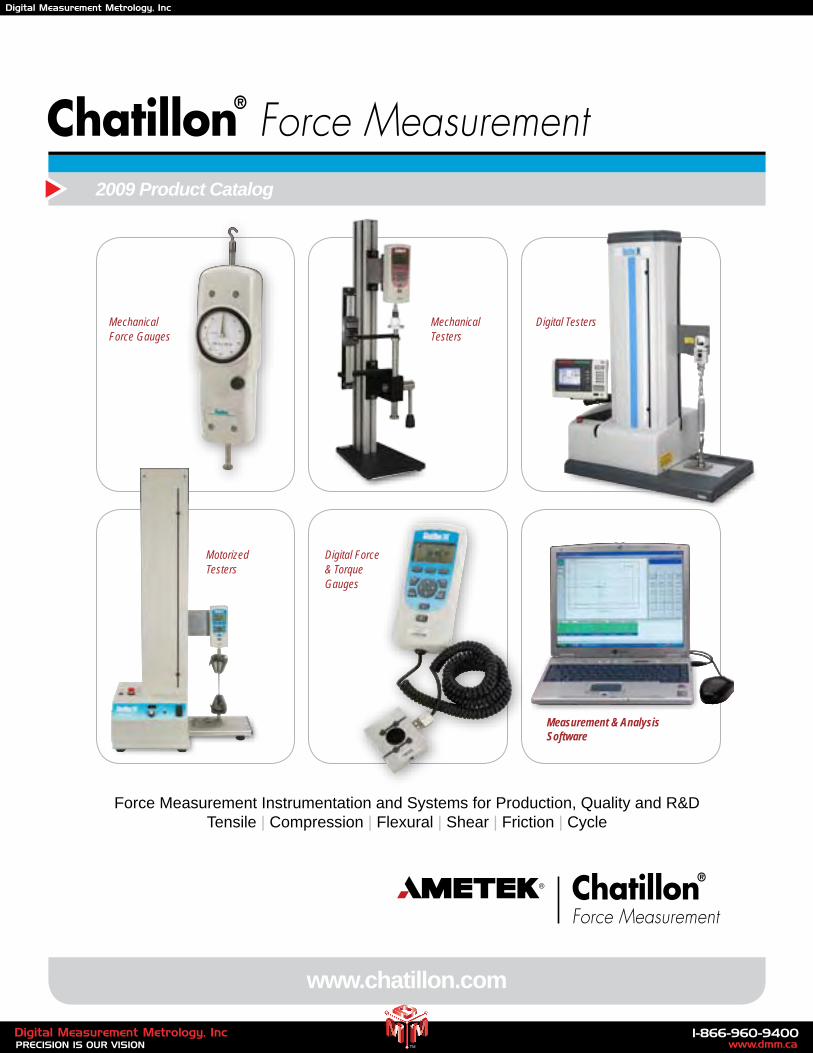
Force Measurement Instrumentation and Systems for Production, Quality and R&DTensile | Compression | Flexural | Shear | Friction | Cycle
www.chatillon.com
2009 Product Catalog
MechanicalTesters
Digital TestersMechanicalForce Gauges
Measurement & Analysis Software
MotorizedTesters
Digital Force & TorqueGauges
www.dmm.ca1-866-960-9400
PRECISION IS OUR VISIONDigital Measurement Metrology, Inc
TM
Digital Measurement Metrology, Inc
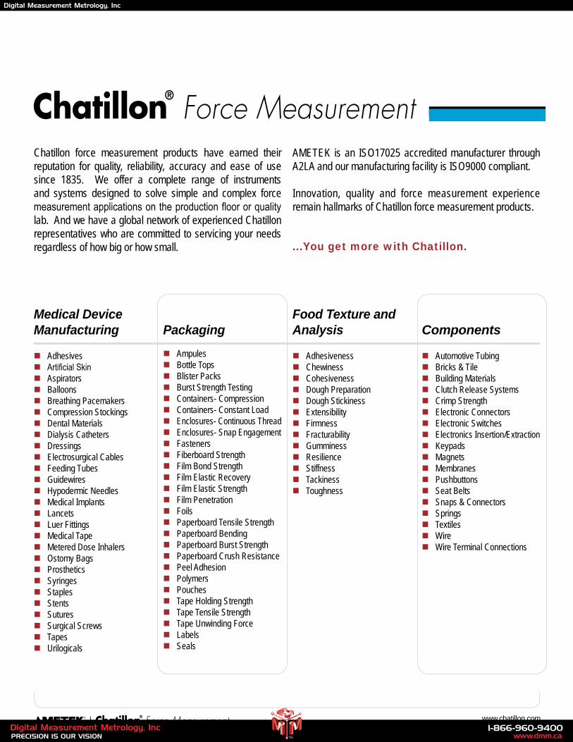
Chatillon force measurement products have earned their reputation for quality, reliability, accuracy and ease of use since 1835. We offer a complete range of instruments and systems designed to solve simple and complex force measurement applications on the production floor or quality lab. And we have a global network of experienced Chatillon representatives who are committed to servicing your needs regardless of how big or how small.
AMETEK is an ISO17025 accredited manufacturer through A2LA and our manufacturing facility is ISO9000 compliant.
Innovation, quality and force measurement experience remain hallmarks of Chatillon force measurement products.
...You get more with Chatillon.
Medical Device Manufacturing
nAdhesivesnArtificial SkinnAspiratorsnBalloonsnBreathing PacemakersnCompression StockingsnDental MaterialsnDialysis CathetersnDressingsnElectrosurgical CablesnFeeding TubesnGuidewiresnHypodermic NeedlesnMedical ImplantsnLancetsnLuer FittingsnMedical TapenMetered Dose InhalersnOstomy BagsnProstheticsnSyringesnStaplesnStentsnSuturesnSurgical ScrewsnTapesnUrilogicals
PackagingnAmpulesnBottle TopsnBlister PacksnBurst Strength TestingnContainers- CompressionnContainers- Constant LoadnEnclosures- Continuous ThreadnEnclosures- Snap EngagementnFastenersnFiberboard StrengthnFilm Bond StrengthnFilm Elastic RecoverynFilm Elastic StrengthnFilm PenetrationnFoilsnPaperboard Tensile StrengthnPaperboard BendingnPaperboard Burst StrengthnPaperboard Crush ResistancenPeel AdhesionnPolymersnPouchesnTape Holding StrengthnTape Tensile StrengthnTape Unwinding ForcenLabelsnSeals
Food Texture and Analysis
nAdhesivenessnChewinessnCohesivenessnDough PreparationnDough StickinessnExtensibilitynFirmnessnFracturabilitynGumminessnResiliencenStiffnessnTackinessnToughness
Components
nAutomotive TubingnBricks & TilenBuilding MaterialsnClutch Release SystemsnCrimp StrengthnElectronic ConnectorsnElectronic SwitchesnElectronics Insertion/ExtractionnKeypadsnMagnetsnMembranesnPushbuttonsnSeat BeltsnSnaps & ConnectorsnSpringsnTextilesnWirenWire Terminal Connections
2 www.chatillon.com
www.dmm.ca1-866-960-9400
PRECISION IS OUR VISIONDigital Measurement Metrology, Inc
TM
Digital Measurement Metrology, Inc
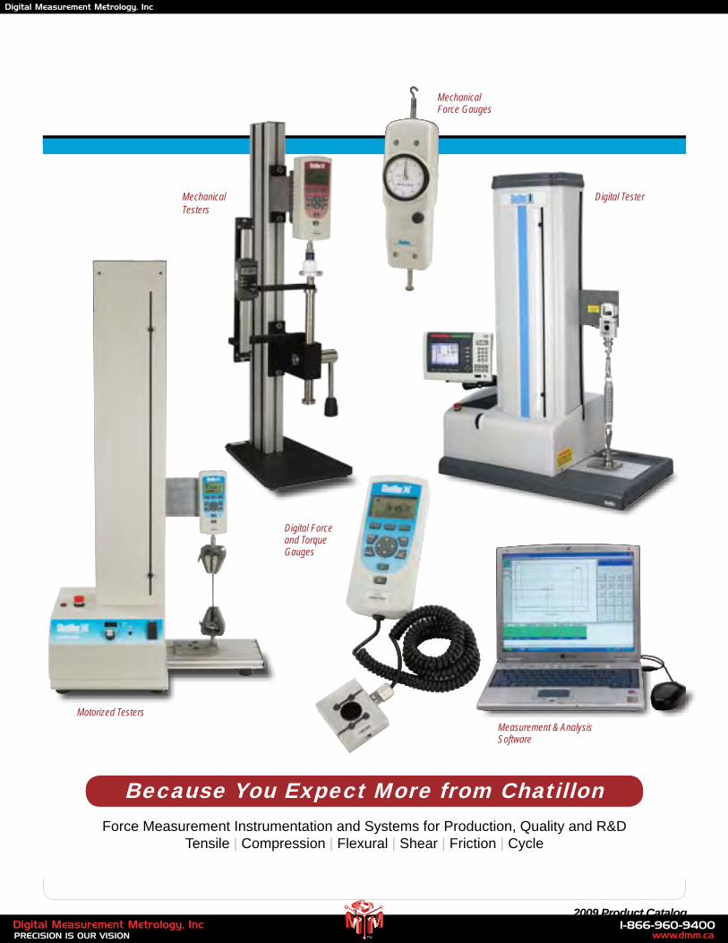
Because You Expect More from Chatillon
Motorized Testers
Mechanical Testers
Digital Testers
MechanicalForce Gauges
Measurement & Analysis Software
Force Measurement Instrumentation and Systems for Production, Quality and R&DTensile | Compression | Flexural | Shear | Friction | Cycle
3 2009 Product Catalog
Digital Force and TorqueGauges
Digital Tester
www.dmm.ca1-866-960-9400
PRECISION IS OUR VISIONDigital Measurement Metrology, Inc
TM
Digital Measurement Metrology, Inc
4 www.chatillon.com
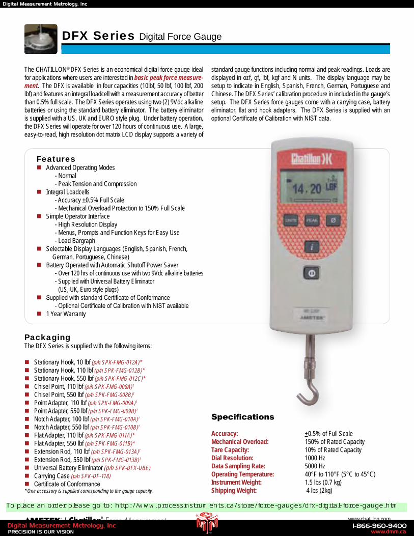
DFX Series Digital Force Gauge
The CHATILLON® DFX Series is an economical digital force gauge ideal for applications where users are interested in basic peak force measure-ment. The DFX is available in four capacities (10lbf, 50 lbf, 100 lbf, 200 lbf) and features an integral loadcell with a measurement accuracy of better than 0.5% full scale. The DFX Series operates using two (2) 9Vdc alkaline batteries or using the standard battery eliminator. The battery eliminator is supplied with a US, UK and EURO style plug. Under battery operation, the DFX Series will operate for over 120 hours of continuous use. A large, easy-to-read, high resolution dot matrix LCD display supports a variety of
standard gauge functions including normal and peak readings. Loads are displayed in ozf, gf, lbf, kgf and N units. The display language may be setup to indicate in English, Spanish, French, German, Portuguese and Chinese. The DFX Series’ calibration procedure in included in the gauge’s setup. The DFX Series force gauges come with a carrying case, battery eliminator, flat and hook adapters. The DFX Series is supplied with an optional Certificate of Calibration with NIST data.
Specifications
Accuracy: +0.5% of Full ScaleMechanical Overload: 150% of Rated Capacity Tare Capacity: 10% of Rated CapacityDial Resolution: 1000 HzData Sampling Rate: 5000 HzOperating Temperature: 40°F to 110°F (5°C to 45°C)Instrument Weight: 1.5 lbs (0.7 kg)Shipping Weight: 4 lbs (2kg)
Featuresn Advanced Operating Modes - Normal - Peak Tension and Compressionn Integral Loadcells - Accuracy +0.5% Full Scale - Mechanical Overload Protection to 150% Full Scalen Simple Operator Interface - High Resolution Display - Menus, Prompts and Function Keys for Easy Use - Load Bargraphn Selectable Display Languages (English, Spanish, French, German, Portuguese, Chinese)n Battery Operated with Automatic Shutoff Power Saver - Over 120 hrs of continuous use with two 9Vdc alkaline batteries - Supplied with Universal Battery Eliminator
(US, UK, Euro style plugs)n Supplied with standard Certificate of Conformance - Optional Certificate of Calibration with NIST available n 1 Year Warranty
PackagingThe DFX Series is supplied with the following items:
n Stationary Hook, 10 lbf (p/n SPK-FMG-012A)*n Stationary Hook, 110 lbf (p/n SPK-FMG-012B)*n Stationary Hook, 550 lbf (p/n SPK-FMG-012C)*n Chisel Point, 110 lbf (p/n SPK-FMG-008A)1
n Chisel Point, 550 lbf (p/n SPK-FMG-008B)1
n Point Adapter, 110 lbf (p/n SPK-FMG-009A)1
n Point Adapter, 550 lbf (p/n SPK-FMG-009B)1
n Notch Adapter, 100 lbf (p/n SPK-FMG-010A)1
n Notch Adapter, 550 lbf (p/n SPK-FMG-010B)1
n Flat Adapter, 110 lbf (p/n SPK-FMG-011A)*n Flat Adapter, 550 lbf (p/n SPK-FMG-011B)*n Extension Rod, 110 lbf (p/n SPK-FMG-013A)1
n Extension Rod, 550 lbf (p/n SPK-FMG-013B)1
n Universal Battery Eliminator (p/n SPK-DFX-UBE)n Carrying Case (p/n SPK-DF-118)n Certificate of Conformance* One accessory is supplied corresponding to the gauge capacity.
www.dmm.ca1-866-960-9400
PRECISION IS OUR VISIONDigital Measurement Metrology, Inc
TM
Digital Measurement Metrology, Inc
5 2009 Product Catalog
Ordering
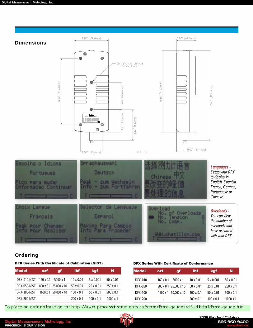
DFX Series With Certificate of Calibration (NIST)
Model ozf gf lbf kgf N
DFX-010-NIST 160 x 0.1 5000 x 1 10 x 0.01 5 x 0.001 50 x 0.01
DFX-050-NIST 800 x 0.1 25,000 x 10 50 x 0.01 25 x 0.01 250 x 0.1
DFX-100-NIST 1600 x 1 50,000 x 10 100 x 0.1 50 x 0.01 500 x 0.1
DFX-200-NIST - - 200 x 0.1 100 x 0.1 1000 x 1
Languages - Setup your DFX to display in English, Spanish, French, German, Portuguese or Chinese.
Dimensions
DFX Series With Certificate of Conformance
Model ozf gf lbf kgf N
DFX-010 160 x 0.1 5000 x 1 10 x 0.01 5 x 0.001 50 x 0.01
DFX-050 800 x 0.1 25,000 x 10 50 x 0.01 25 x 0.01 250 x 0.1
DFX-100 1600 x 1 50,000 x 10 100 x 0.1 50 x 0.01 500 x 0.1
DFX-200 - - 200 x 0.1 100 x 0.1 1000 x 1
Overloads - You can view the number of overloads that have occurred with your DFX.
www.dmm.ca1-866-960-9400
PRECISION IS OUR VISIONDigital Measurement Metrology, Inc
TM
Digital Measurement Metrology, Inc
6 www.chatillon.com
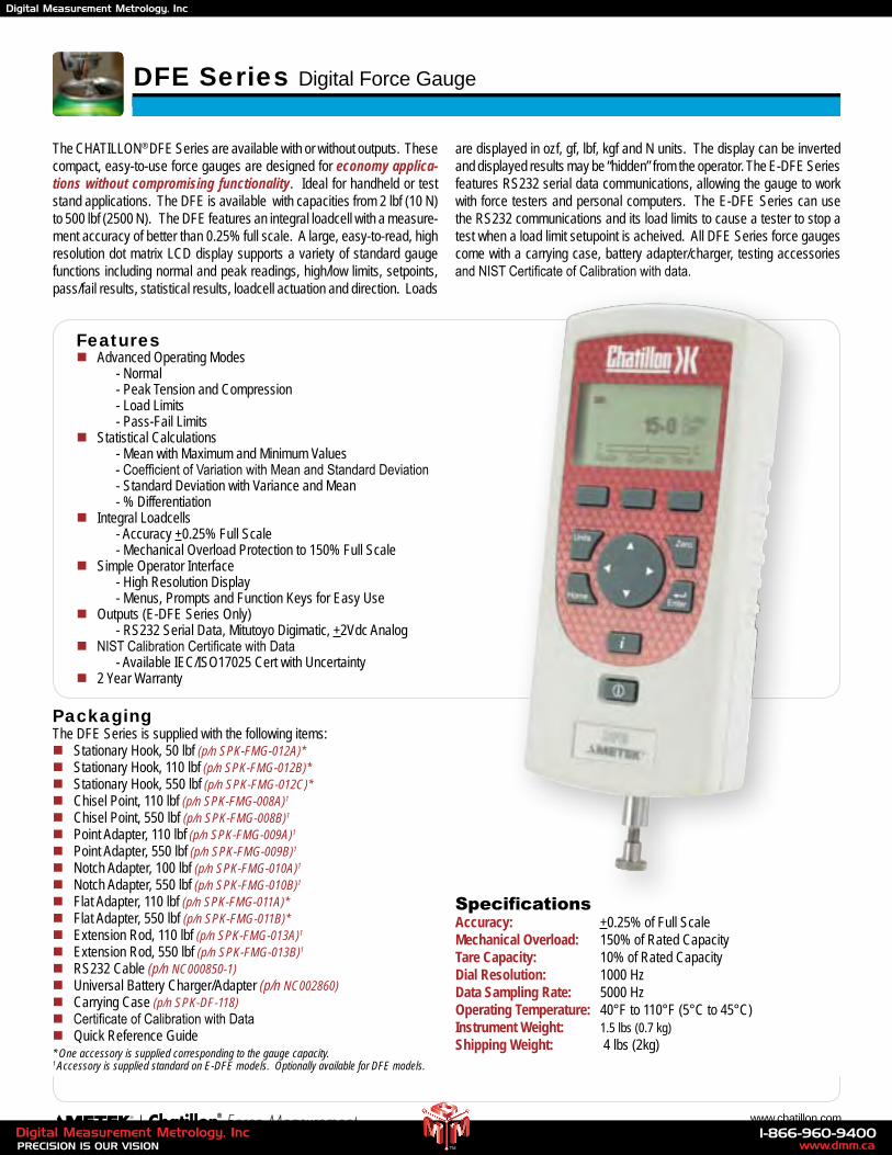
The CHATILLON® DFE Series are available with or without outputs. These compact, easy-to-use force gauges are designed for economy applica-tions without compromising functionality. Ideal for handheld or test stand applications. The DFE is available with capacities from 2 lbf (10 N) to 500 lbf (2500 N). The DFE features an integral loadcell with a measure-ment accuracy of better than 0.25% full scale. A large, easy-to-read, high resolution dot matrix LCD display supports a variety of standard gauge functions including normal and peak readings, high/low limits, setpoints, pass/fail results, statistical results, loadcell actuation and direction. Loads
are displayed in ozf, gf, lbf, kgf and N units. The display can be inverted and displayed results may be “hidden” from the operator. The E-DFE Series features RS232 serial data communications, allowing the gauge to work with force testers and personal computers. The E-DFE Series can use the RS232 communications and its load limits to cause a tester to stop a test when a load limit setupoint is acheived. All DFE Series force gauges come with a carrying case, battery adapter/charger, testing accessories and NIST Certificate of Calibration with data.
Featuresn Advanced Operating Modes - Normal - Peak Tension and Compression - Load Limits - Pass-Fail Limitsn Statistical Calculations - Mean with Maximum and Minimum Values - Coefficient of Variation with Mean and Standard Deviation - Standard Deviation with Variance and Mean - % Differentiationn Integral Loadcells - Accuracy +0.25% Full Scale - Mechanical Overload Protection to 150% Full Scalen Simple Operator Interface - High Resolution Display - Menus, Prompts and Function Keys for Easy Usen Outputs (E-DFE Series Only) - RS232 Serial Data, Mitutoyo Digimatic, +2Vdc Analogn NIST Calibration Certificate with Data - Available IEC/ISO17025 Cert with Uncertaintyn 2 Year Warranty
SpecificationsAccuracy: +0.25% of Full ScaleMechanical Overload: 150% of Rated Capacity Tare Capacity: 10% of Rated CapacityDial Resolution: 1000 HzData Sampling Rate: 5000 HzOperating Temperature: 40°F to 110°F (5°C to 45°C)Instrument Weight: 1.5 lbs (0.7 kg)Shipping Weight: 4 lbs (2kg)
DFE Series Digital Force Gauge
PackagingThe DFE Series is supplied with the following items:n Stationary Hook, 50 lbf (p/n SPK-FMG-012A)*n Stationary Hook, 110 lbf (p/n SPK-FMG-012B)*n Stationary Hook, 550 lbf (p/n SPK-FMG-012C)*n Chisel Point, 110 lbf (p/n SPK-FMG-008A)1
n Chisel Point, 550 lbf (p/n SPK-FMG-008B)1
n Point Adapter, 110 lbf (p/n SPK-FMG-009A)1
n Point Adapter, 550 lbf (p/n SPK-FMG-009B)1
n Notch Adapter, 100 lbf (p/n SPK-FMG-010A)1
n Notch Adapter, 550 lbf (p/n SPK-FMG-010B)1
n Flat Adapter, 110 lbf (p/n SPK-FMG-011A)*n Flat Adapter, 550 lbf (p/n SPK-FMG-011B)*n Extension Rod, 110 lbf (p/n SPK-FMG-013A)1
n Extension Rod, 550 lbf (p/n SPK-FMG-013B)1
n RS232 Cable (p/n NC000850-1)n Universal Battery Charger/Adapter (p/n NC002860)n Carrying Case (p/n SPK-DF-118)n Certificate of Calibration with Datan Quick Reference Guide* One accessory is supplied corresponding to the gauge capacity.1 Accessory is supplied standard on E-DFE models. Optionally available for DFE models.
www.dmm.ca1-866-960-9400
PRECISION IS OUR VISIONDigital Measurement Metrology, Inc
TM
Digital Measurement Metrology, Inc
7 2009 Product Catalog
DFE Series Without Outputs
DFE-002 32 x 0.01 1000 x 1 2 x 0.001 1 x 0.001 10 x 0.01
DFE-010 160 x 0.1 5000 x 1 10 x 0.01 5 x 0.001 50 x 0.01
DFE-025 400 x 0.1 10,000 x 10 25 x 0.01 10 x 0.01 100 x 0.1
DFE-050 800 x 0.1 25,000 x 10 50 x 0.01 25 x 0.01 250 x 0.1
DFE-100 1600 x 1 50,000 x 10 100 x 0.1 50 x 0.01 500 x 0.1
DFE-200 - - 200 x 0.1 100 x 0.1 1000 x 1
DFE-500 - - 500 x 0.1 250 x 0.1 2500 x 1
DFE Series With Outputs
Model ozf gf lbf kgf N
E-DFE-002 32 x 0.01 1000 x 1 2 x 0.001 1 x 0.001 10 x 0.01
E-DFE-010 160 x 0.1 5000 x 1 10 x 0.01 5 x 0.001 50 x 0.01
E-DFE-025 400 x 0.1 10,000 x 10 25 x 0.01 10 x 0.01 100 x 0.1
E-DFE-050 800 x 0.1 25,000 x 10 50 x 0.01 25 x 0.01 250 x 0.1
E-DFE-100 1600 x 1 50,000 x 10 100 x 0.1 50 x 0.01 500 x 0.1
E-DFE-200 - - 200 x 0.1 100 x 0.1 1000 x 1
E-DFE-500 - - 500 x 0.1 250 x 0.1 2500 x 1
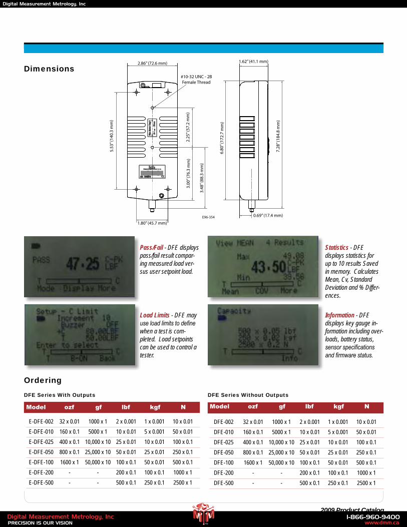
Pass/Fail - DFE displays pass/fail result compar-ing measured load ver-sus user setpoint load.
Load Limits - DFE may use load limits to define when a test is com-pleted. Load setpoints can be used to control a tester.
Statistics - DFE displays statistics for up to 10 results Saved in memory. Calculates Mean, Cv, Standard Deviation and % Differ-ences.
Information - DFE displays key gauge in-formation including over-loads, battery status, sensor specifications and firmware status.
Model ozf gf lbf kgf N
2.86” (72.6 mm)
1.80” (45.7 mm)
3.00
” (76
.3 m
m)
3.48
” (88
.3 m
m)
2.25
” (57
.2 m
m)
5.53
” (14
0.3
mm
)
0.69” (17.4 mm)
1.62” (41.1 mm)
6.80
” (17
2.7
mm
)
7.28
” (18
4.8
mm
)
#10-32 UNC - 2BFemale Thread
E96-354
Ordering
Dimensions
www.dmm.ca1-866-960-9400
PRECISION IS OUR VISIONDigital Measurement Metrology, Inc
TM
Digital Measurement Metrology, Inc
8 www.chatillon.com
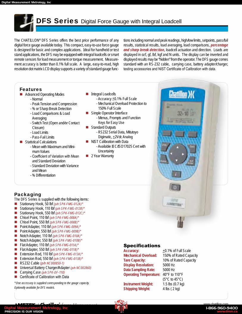
The CHATILLON® DFS Series offers the best price performance of any digital force gauge available today. This compact, easy-to-use force gauge is designed for basic and complex applications. Ideal for handheld or test stand applications, the DFS may be equipped with integral loadcells or smart remote sensors for load measurement or torque measurement. Measure-ment accuracy is better than 0.1% full scale. A large, easy-to-read, high resolution dot matrix LCD display supports a variety of standard gauge func-
tions including normal and peak readings, high/low limits, setpoints, pass/fail results, statistical results, load averaging, load comparisons, percentage and sharp break detection, loadcell actuation and direction. Loads are displayed in ozf, gf, lbf, kgf and N units. The display can be inverted and displayed results may be “hidden” from the operator. The DFS gauge comes standard with an RS-232 cable, carrying case, battery adapter/charger, testing accessories and NIST Certificate of Calibration with data.
SpecificationsAccuracy: +0.1% of Full ScaleMechanical Overload: 150% of Rated Capacity Tare Capacity: 10% of Rated CapacityDisplay Resolution: 5000 HzData Sampling Rate: 5000 HzOperating Temperature: 40°F to 110°F (5°C to 45°C)Instrument Weight: 1.5 lbs (0.7 kg)Shipping Weight: 4 lbs ( 2 kg)
PackagingThe DFS Series is supplied with the following items:n Stationary Hook, 50 lbf (p/n SPK-FMG-012A)*n Stationary Hook, 110 lbf (p/n SPK-FMG-012B)*n Stationary Hook, 550 lbf (p/n SPK-FMG-012C)*n Chisel Point, 110 lbf (p/n SPK-FMG-008A)*n Chisel Point, 550 lbf (p/n SPK-FMG-008B)*n Point Adapter, 110 lbf (p/n SPK-FMG-009A)*n Point Adapter, 550 lbf (p/n SPK-FMG-009B)*n Notch Adapter, 110 lbf (p/n SPK-FMG-010A)*n Notch Adapter, 550 lbf (p/n SPK-FMG-010B)*n Flat Adapter, 110 lbf (p/n SPK-FMG-011A)*n Flat Adapter, 550 lbf (p/n SPK-FMG-011B)*n Extension Rod, 110 lbf (p/n SPK-FMG-013A)*n Extension Rod, 550 lbf (p/n SPK-FMG-013B)*n RS232 Cable (p/n NC000850-1)n Universal Battery Charger/Adapter (p/n NC002860)n Carrying Case (p/n SPK-DF-118)n Certificate of Calibration with Data
* One accessory is supplied corresponding to the gauge capacity.
Optionally available for DFS models.
DFS Series Digital Force Gauge with Integral Loadcell
Featuresn Advanced Operating Modes - Normal - Peak Tension and Compression - % or Sharp Break Detection - Load Comparisons & Load
Averaging - Switch Test (Open and/or Contact
Closure) - Load Limits - Pass-Fail Limitsn Statistical Calculations - Mean with Maximum and Mini-
mum Values - Coefficient of Variation with Mean
and Standard Deviation - Standard Deviation with Variance
and Mean - % Differentiation
n Integral Loadcells - Accuracy +0.1% Full Scale - Mechanical Overload Protection to
150% Full Scalen Simple Operator Interface - Menus, Prompts and Function
Keys for Easy Usen Standard Outputs - RS232 Serial Data, Mitutoyo
Digimatic, +2Vdc Analogn NIST Calibration with Data - Available IEC/ISO17025 Cert with
Uncertaintyn 2 Year Warranty
www.dmm.ca1-866-960-9400
PRECISION IS OUR VISIONDigital Measurement Metrology, Inc
TM
Digital Measurement Metrology, Inc
9 2009 Product Catalog
Ordering
DFS Series With Integral Load Sensor
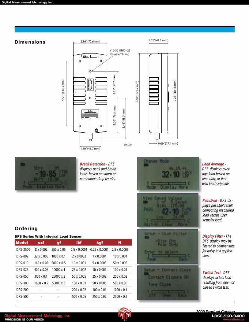
DFS-250G 8 x 0.002 250 x 0.05 0.5 x 0.0001 0.25 x 0.0001 2.5 x 0.0005
DFS-002 32 x 0.005 1000 x 0.1 2 x 0.0002 1 x 0.0001 10 x 0.001
DFS-010 160 x 0.02 5000 x 0.5 10 x 0.001 5 x 0.0005 50 x 0.005
DFS-025 400 x 0.05 10000 x 1 25 x 0.002 10 x 0.001 100 x 0.01
DFS-050 800 x 0.1 25000 x 2 50 x 0.005 25 x 0.002 250 x 0.02
DFS-100 1600 x 0.2 50000 x 5 100 x 0.01 50 x 0.005 500 x 0.05
DFS-200 - - 200 x 0.02 100 x 0.01 1000 x 0.1
DFS-500 - - 500 x 0.05 250 x 0.02 2500 x 0.2
Display Filter - The DFS display may be filtered to compensate for noisy test applica-tions.
Switch Test - DFS displays actual load resulting from open or closed switch test.
Model ozf gf lbf kgf N
2.86” (72.6 mm)
1.80” (45.7 mm)
3.00
” (76
.3 m
m)
3.48
” (88
.3 m
m)
2.25
” (57
.2 m
m)
5.53
” (14
0.3
mm
)
0.69” (17.4 mm)
1.62” (41.1 mm)
6.80
” (17
2.7
mm
)
7.28
” (18
4.8
mm
)
#10-32 UNC - 2BFemale Thread
E96-354
Break Detection - DFS displays peak and break loads based on sharp or percentage drop results.
Pass/Fail - DFS dis-plays pass/fail result comparing measured load versus user setpoint load.
Load Average - DFS displays aver-age load based on time only, or time with load setpoints.
Dimensions
www.dmm.ca1-866-960-9400
PRECISION IS OUR VISIONDigital Measurement Metrology, Inc
TM
Digital Measurement Metrology, Inc
10 www.chatillon.com
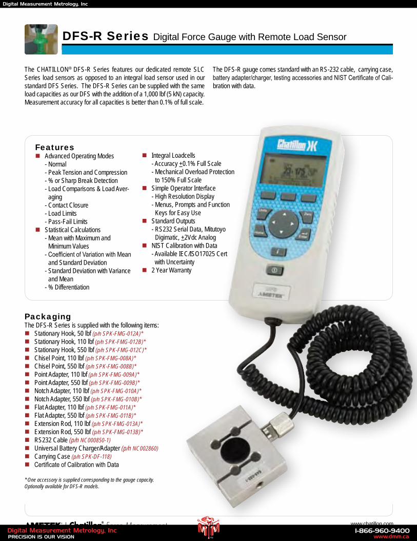
DFS-R Series Digital Force Gauge with Remote Load Sensor
The CHATILLON® DFS-R Series features our dedicated remote SLC Series load sensors as opposed to an integral load sensor used in our standard DFS Series. The DFS-R Series can be supplied with the same load capacities as our DFS with the addition of a 1,000 lbf (5 kN) capacity. Measurement accuracy for all capacities is better than 0.1% of full scale.
The DFS-R gauge comes standard with an RS-232 cable, carrying case, battery adapter/charger, testing accessories and NIST Certificate of Cali-bration with data.
Featuresn Advanced Operating Modes - Normal - Peak Tension and Compression - % or Sharp Break Detection - Load Comparisons & Load Aver-
aging - Contact Closure - Load Limits - Pass-Fail Limitsn Statistical Calculations - Mean with Maximum and
Minimum Values - Coefficient of Variation with Mean
and Standard Deviation - Standard Deviation with Variance
and Mean - % Differentiation
n Integral Loadcells - Accuracy +0.1% Full Scale - Mechanical Overload Protection
to 150% Full Scalen Simple Operator Interface - High Resolution Display - Menus, Prompts and Function
Keys for Easy Usen Standard Outputs - RS232 Serial Data, Mitutoyo
Digimatic, +2Vdc Analogn NIST Calibration with Data - Available IEC/ISO17025 Cert
with Uncertaintyn 2 Year Warranty
PackagingThe DFS-R Series is supplied with the following items:n Stationary Hook, 50 lbf (p/n SPK-FMG-012A)*n Stationary Hook, 110 lbf (p/n SPK-FMG-012B)*n Stationary Hook, 550 lbf (p/n SPK-FMG-012C)*n Chisel Point, 110 lbf (p/n SPK-FMG-008A)*n Chisel Point, 550 lbf (p/n SPK-FMG-008B)*n Point Adapter, 110 lbf (p/n SPK-FMG-009A)*n Point Adapter, 550 lbf (p/n SPK-FMG-009B)*n Notch Adapter, 110 lbf (p/n SPK-FMG-010A)*n Notch Adapter, 550 lbf (p/n SPK-FMG-010B)*n Flat Adapter, 110 lbf (p/n SPK-FMG-011A)*n Flat Adapter, 550 lbf (p/n SPK-FMG-011B)*n Extension Rod, 110 lbf (p/n SPK-FMG-013A)*n Extension Rod, 550 lbf (p/n SPK-FMG-013B)*n RS232 Cable (p/n NC000850-1)n Universal Battery Charger/Adapter (p/n NC002860)n Carrying Case (p/n SPK-DF-118)n Certificate of Calibration with Data
* One accessory is supplied corresponding to the gauge capacity.Optionally available for DFS-R models.
www.dmm.ca1-866-960-9400
PRECISION IS OUR VISIONDigital Measurement Metrology, Inc
TM
Digital Measurement Metrology, Inc
11 2009 Product Catalog
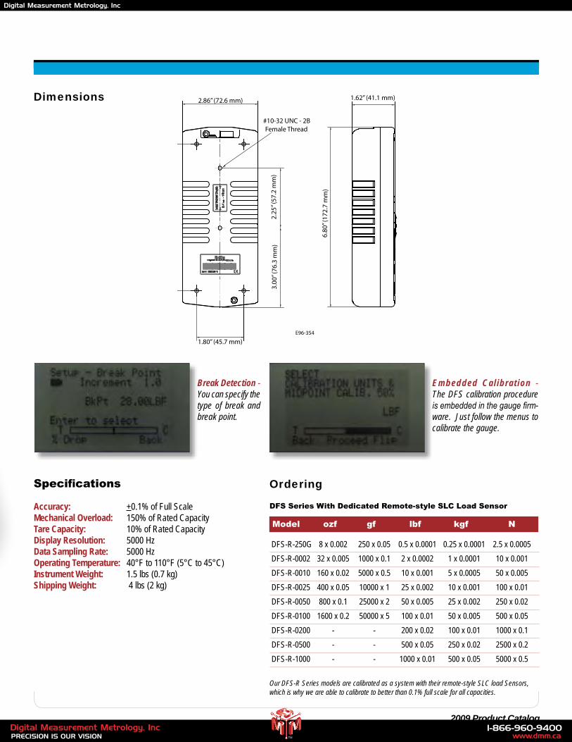
Dimensions
Specifications
Accuracy: +0.1% of Full ScaleMechanical Overload: 150% of Rated Capacity Tare Capacity: 10% of Rated CapacityDisplay Resolution: 5000 HzData Sampling Rate: 5000 HzOperating Temperature: 40°F to 110°F (5°C to 45°C)Instrument Weight: 1.5 lbs (0.7 kg)Shipping Weight: 4 lbs (2 kg)
Break Detection - You can specify the type of break and break point.
Embedded Calibration - The DFS calibration procedure is embedded in the gauge firm-ware. Just follow the menus to calibrate the gauge.
Ordering
DFS Series With Dedicated Remote-style SLC Load Sensor
Model ozf gf lbf kgf N
DFS-R-250G 8 x 0.002 250 x 0.05 0.5 x 0.0001 0.25 x 0.0001 2.5 x 0.0005
DFS-R-0002 32 x 0.005 1000 x 0.1 2 x 0.0002 1 x 0.0001 10 x 0.001
DFS-R-0010 160 x 0.02 5000 x 0.5 10 x 0.001 5 x 0.0005 50 x 0.005
DFS-R-0025 400 x 0.05 10000 x 1 25 x 0.002 10 x 0.001 100 x 0.01
DFS-R-0050 800 x 0.1 25000 x 2 50 x 0.005 25 x 0.002 250 x 0.02
DFS-R-0100 1600 x 0.2 50000 x 5 100 x 0.01 50 x 0.005 500 x 0.05
DFS-R-0200 - - 200 x 0.02 100 x 0.01 1000 x 0.1
DFS-R-0500 - - 500 x 0.05 250 x 0.02 2500 x 0.2
DFS-R-1000 - - 1000 x 0.01 500 x 0.05 5000 x 0.5
Our DFS-R Series models are calibrated as a system with their remote-style SLC load Sensors, which is why we are able to calibrate to better than 0.1% full scale for all capacities.
2.86” (72.6 mm)
1.80” (45.7 mm)
3.00
” (76
.3 m
m)
2.25
” (57
.2 m
m)
5.53
” (14
0.3
mm
)
1.62” (41.1 mm)
6.80
” (17
2.7
mm
)
#10-32 UNC - 2B Female Thread
E96-354
www.dmm.ca1-866-960-9400
PRECISION IS OUR VISIONDigital Measurement Metrology, Inc
TM
Digital Measurement Metrology, Inc
12 www.chatillon.com
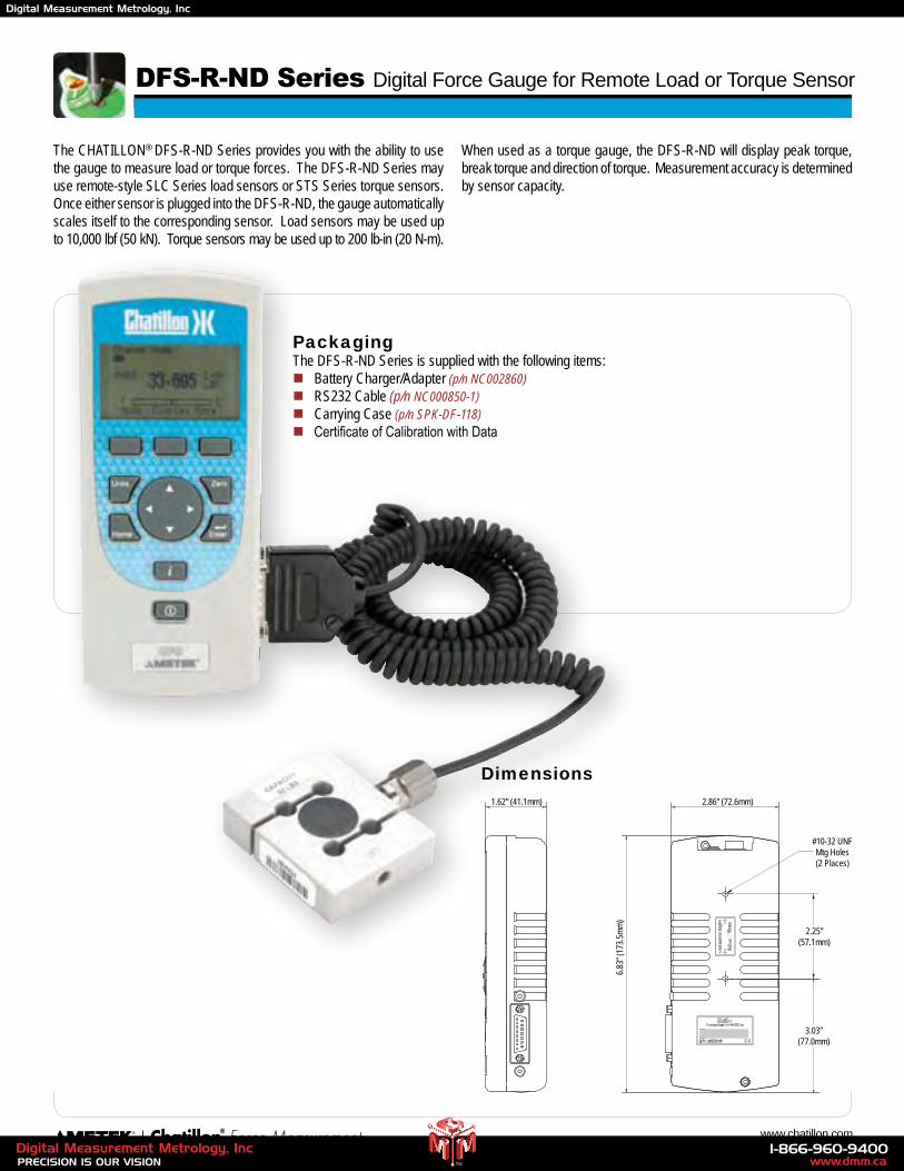
The CHATILLON® DFS-R-ND Series provides you with the ability to use the gauge to measure load or torque forces. The DFS-R-ND Series may use remote-style SLC Series load sensors or STS Series torque sensors. Once either sensor is plugged into the DFS-R-ND, the gauge automatically scales itself to the corresponding sensor. Load sensors may be used up to 10,000 lbf (50 kN). Torque sensors may be used up to 200 lb-in (20 N-m).
When used as a torque gauge, the DFS-R-ND will display peak torque, break torque and direction of torque. Measurement accuracy is determined by sensor capacity.
E 9 6 - 3 5 3
1.62” (41.1mm) 2.86” (72.6mm)
2.25”(57.1mm)
3.03”(77.0mm)
#10-32 UNFMtg Holes(2 Places)
6.83”
(173
.5mm)
DFS-R-ND Series Digital Force Gauge for Remote Load or Torque Sensor
PackagingThe DFS-R-ND Series is supplied with the following items:n Battery Charger/Adapter (p/n NC002860)n RS232 Cable (p/n NC000850-1)n Carrying Case (p/n SPK-DF-118)n Certificate of Calibration with Data
Dimensions
www.dmm.ca1-866-960-9400
PRECISION IS OUR VISIONDigital Measurement Metrology, Inc
TM
Digital Measurement Metrology, Inc
13 2009 Product Catalog
Ordering
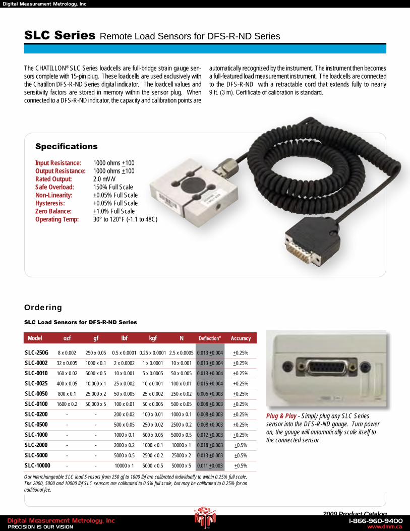
Our interchangeable SLC load Sensors from 250 gf to 1000 lbf are calibrated individually to within 0.25% full scale. The 2000, 5000 and 10000 lbf SLC sensors are calibrated to 0.5% full scale, but may be calibrated to 0.25% for an additional fee.
Model ozf gf lbf kgf N Deflection” Accuracy
SLC-250G 8 x 0.002 250 x 0.05 0.5 x 0.0001 0.25 x 0.0001 2.5 x 0.0005 0.013 +0.004 +0.25%
SLC-0002 32 x 0.005 1000 x 0.1 2 x 0.0002 1 x 0.0001 10 x 0.001 0.013 +0.004 +0.25%
SLC-0010 160 x 0.02 5000 x 0.5 10 x 0.001 5 x 0.0005 50 x 0.005 0.013 +0.004 +0.25%
SLC-0025 400 x 0.05 10,000 x 1 25 x 0.002 10 x 0.001 100 x 0.01 0.015 +0.004 +0.25%
SLC-0050 800 x 0.1 25,000 x 2 50 x 0.005 25 x 0.002 250 x 0.02 0.006 +0.003 +0.25%
SLC-0100 1600 x 0.2 50,000 x 5 100 x 0.01 50 x 0.005 500 x 0.05 0.008 +0.003 +0.25%
SLC-0200 - - 200 x 0.02 100 x 0.01 1000 x 0.1 0.008 +0.003 +0.25%
SLC-0500 - - 500 x 0.05 250 x 0.02 2500 x 0.2 0.008 +0.003 +0.25%
SLC-1000 - - 1000 x 0.1 500 x 0.05 5000 x 0.5 0.012 +0.003 +0.25%
SLC-2000 - - 2000 x 0.2 1000 x 0.1 10000 x 1 0.018 +0.003 +0.5%
SLC-5000 - - 5000 x 0.5 2500 x 0.2 25000 x 2 0.013 +0.003 +0.5%
SLC-10000 - - 10000 x 1 5000 x 0.5 50000 x 5 0.011 +0.003 +0.5%
Plug & Play - Simply plug any SLC Series sensor into the DFS-R-ND gauge. Turn power on, the gauge will automatically scale itself to the connected sensor.
The CHATILLON® SLC Series loadcells are full-bridge strain gauge sen-sors complete with 15-pin plug. These loadcells are used exclusively with the Chatillon DFS-R-ND Series digital indicator. The loadcell values and sensitivity factors are stored in memory within the sensor plug. When connected to a DFS-R-ND indicator, the capacity and calibration points are
automatically recognized by the instrument. The instrument then becomes a full-featured load measurement instrument. The loadcells are connected to the DFS-R-ND with a retractable cord that extends fully to nearly 9 ft. (3 m). Certificate of calibration is standard.
Specifications
Input Resistance: 1000 ohms +100 Output Resistance: 1000 ohms +100Rated Output: 2.0 mV/VSafe Overload: 150% Full ScaleNon-Linearity: +0.05% Full ScaleHysteresis: +0.05% Full ScaleZero Balance: +1.0% Full ScaleOperating Temp: 30° to 120°F (-1.1 to 48C)
SLC Load Sensors for DFS-R-ND Series
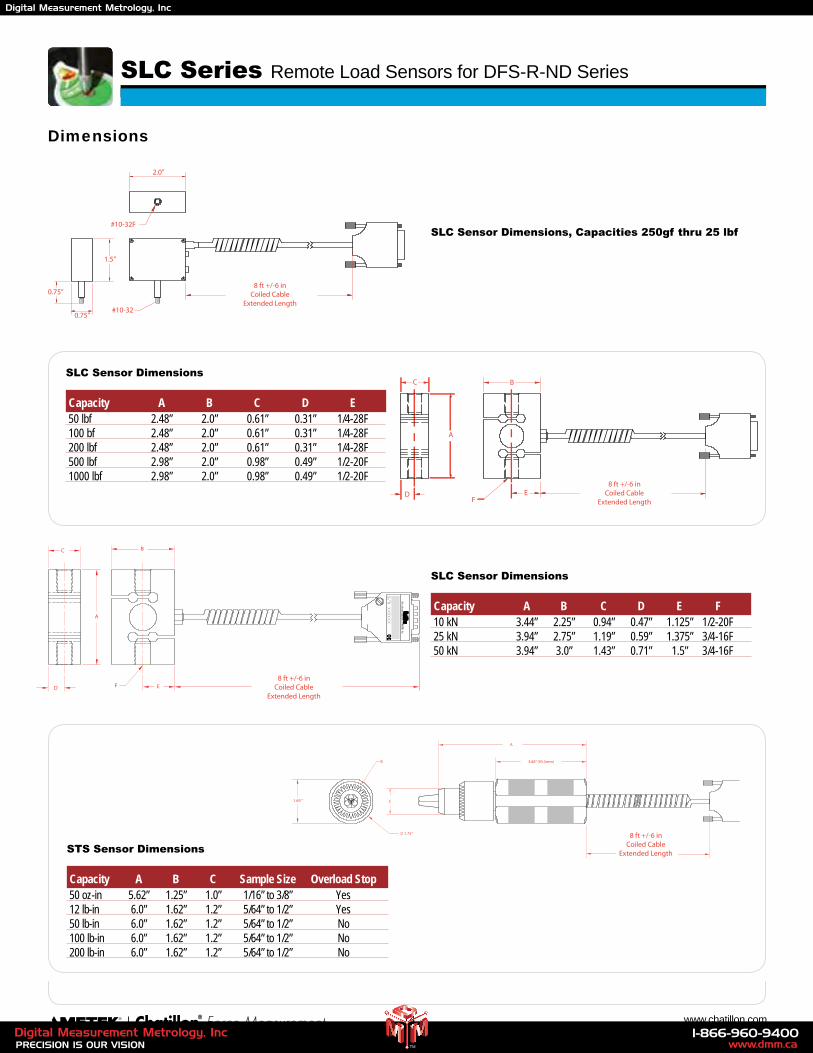
SLC Series Remote Load Sensors for DFS-R-ND Series
www.dmm.ca1-866-960-9400
PRECISION IS OUR VISIONDigital Measurement Metrology, Inc
TM
Digital Measurement Metrology, Inc
14 www.chatillon.com
Dimensions
1.75”
1.69 ”
8 ft +/-6 inCoiled Cable
Extended Length
A
3.68” (93.5mm)
C
B
SLC Sensor Dimensions, Capacities 250gf thru 25 lbf
STS Sensor Dimensions
Capacity A B C Sample Size Overload Stop 50 oz-in 5.62” 1.25” 1.0” 1/16” to 3/8” Yes 12 lb-in 6.0” 1.62” 1.2” 5/64” to 1/2” Yes 50 lb-in 6.0” 1.62” 1.2” 5/64” to 1/2” No 100 lb-in 6.0” 1.62” 1.2” 5/64” to 1/2” No 200 lb-in 6.0” 1.62” 1.2” 5/64” to 1/2” No
8 ft +/-6 inCoiled Cable
Extended LengthF
A
BC
D E
#10-32
1.5”
#10-32F
0.75”
0.75”
2.0”
8 ft +/-6 inCoiled Cable
Extended Length
E F
B
A
C
D
SLC Sensor Dimensions
Capacity A B C D E F 10 kN 3.44” 2.25” 0.94” 0.47” 1.125” 1/2-20F 25 kN 3.94” 2.75” 1.19” 0.59” 1.375” 3/4-16F 50 kN 3.94” 3.0” 1.43” 0.71” 1.5” 3/4-16F
8 ft +/-6 inCoiled Cable
Extended LengthF
A
BC
D E
8 ft +/-6 inCoiled Cable
Extended LengthF
A
BC
D E
SLC Series Remote Load Sensors for DFS-R-ND Series
SLC Sensor Dimensions
Capacity A B C D E 50 lbf 2.48” 2.0” 0.61” 0.31” 1/4-28F 100 bf 2.48” 2.0” 0.61” 0.31” 1/4-28F 200 lbf 2.48” 2.0” 0.61” 0.31” 1/4-28F 500 lbf 2.98” 2.0” 0.98” 0.49” 1/2-20F 1000 lbf 2.98” 2.0” 0.98” 0.49” 1/2-20F
www.dmm.ca1-866-960-9400
PRECISION IS OUR VISIONDigital Measurement Metrology, Inc
TM
Digital Measurement Metrology, Inc
15 2009 Product Catalog
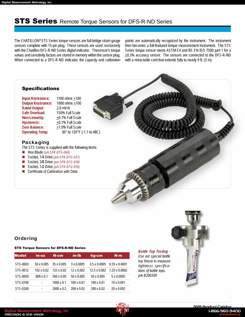
STS Series Remote Torque Sensors for DFS-R-ND Series
Ordering
Model in-oz N-cm in-lb kg-cm N-m
STS-0003 50 x 0.005 35 x 0.005 3 x 0.0005 3.5 x 0.0005 0.35 x 0.0001
STS-0012 192 x 0.02 125 x 0.02 12 x 0.002 12.5 x 0.002 1.25 x 0.0002
STS-0050 800 x 0.1 500 x 0.05 50 x 0.005 50 x 0.005 5 x 0.0005
STS-0100 - 1000 x 0.1 100 x 0.01 100 x 0.01 10 x 0.001
STS-0200 - 2000 x 0.2 200 x 0.02 200 x 0.02 20 x 0.002
Specifications
Input Resistance: 1100 ohms +100 Output Resistance: 1000 ohms +100Rated Output: 2.0 mV/VSafe Overload: 150% Full ScaleNon-Linearity: +0.1% Full ScaleHysteresis: +0.1% Full ScaleZero Balance: +1.0% Full ScaleOperating Temp: 30° to 120°F (-1.1 to 48C)
PackagingThe STS Series is supplied with the following items:n Hex Blade (p/n SPK-DTG-040)n Socket, 1/4 Drive (p/n SPK-DTG-037)n Socket, 3/8 Drive (p/n SPK-DTG-038)n Socket, 1/2 Drive (p/n SPK-DTG-039)n Certificate of Calibration with Data
Bottle Top Testing - Use are special bottle top fixture to measure tightness specifica-tions of bottle tops.p/n B200309
The CHATILLON® STS Series torque sensors are full-bridge strain gauge sensors complete with 15-pin plug. These sensors are used exclusively with the Chatillon DFS-R-ND Series digital indicator. Thesensor’s torque values and sensitivity factors are stored in memory within the sensor plug. When connected to a DFS-R-ND indicator, the capacity and calibration
points are automatically recognized by the instrument. The instrument then becomes a full-featured torque measurement instrument. The STS Series torque sensor meets ASTM E4 and BS EN ISO 7500 part 1 for a +0.3% accuracy sensor. The sensors are connected to the DFS-R-ND with a retractable cord that extends fully to nearly 9 ft. (3 m).
STS Torque Sensors for DFS-R-ND Series
www.dmm.ca1-866-960-9400
PRECISION IS OUR VISIONDigital Measurement Metrology, Inc
TM
Digital Measurement Metrology, Inc
16 www.chatillon.com
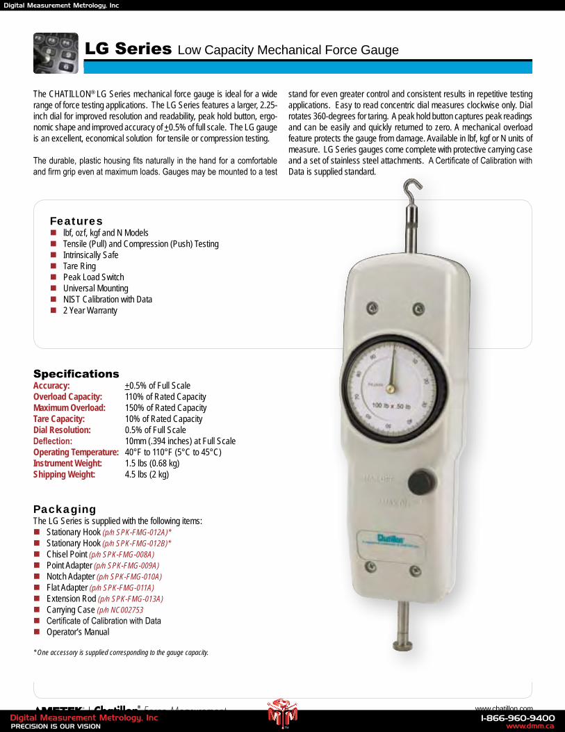
LG Series Low Capacity Mechanical Force Gauge
Featuresn lbf, ozf, kgf and N Modelsn Tensile (Pull) and Compression (Push) Testingn Intrinsically Safen Tare Ringn Peak Load Switchn Universal Mountingn NIST Calibration with Datan 2 Year Warranty
SpecificationsAccuracy: +0.5% of Full ScaleOverload Capacity: 110% of Rated CapacityMaximum Overload: 150% of Rated Capacity Tare Capacity: 10% of Rated CapacityDial Resolution: 0.5% of Full ScaleDeflection: 10mm (.394 inches) at Full ScaleOperating Temperature: 40°F to 110°F (5°C to 45°C)Instrument Weight: 1.5 lbs (0.68 kg)Shipping Weight: 4.5 lbs (2 kg)
PackagingThe LG Series is supplied with the following items:n Stationary Hook (p/n SPK-FMG-012A)*n Stationary Hook (p/n SPK-FMG-012B)*n Chisel Point (p/n SPK-FMG-008A)n Point Adapter (p/n SPK-FMG-009A)n Notch Adapter (p/n SPK-FMG-010A)n Flat Adapter (p/n SPK-FMG-011A)n Extension Rod (p/n SPK-FMG-013A)n Carrying Case (p/n NC002753n Certificate of Calibration with Datan Operator’s Manual
* One accessory is supplied corresponding to the gauge capacity.
The CHATILLON® LG Series mechanical force gauge is ideal for a wide range of force testing applications. The LG Series features a larger, 2.25-inch dial for improved resolution and readability, peak hold button, ergo-nomic shape and improved accuracy of +0.5% of full scale. The LG gauge is an excellent, economical solution for tensile or compression testing.
The durable, plastic housing fits naturally in the hand for a comfortable and firm grip even at maximum loads. Gauges may be mounted to a test
stand for even greater control and consistent results in repetitive testing applications. Easy to read concentric dial measures clockwise only. Dial rotates 360-degrees for taring. A peak hold button captures peak readings and can be easily and quickly returned to zero. A mechanical overload feature protects the gauge from damage. Available in lbf, kgf or N units of measure. LG Series gauges come complete with protective carrying case and a set of stainless steel attachments. A Certificate of Calibration with Data is supplied standard.
www.dmm.ca1-866-960-9400
PRECISION IS OUR VISIONDigital Measurement Metrology, Inc
TM
Digital Measurement Metrology, Inc
17 2009 Product Catalog
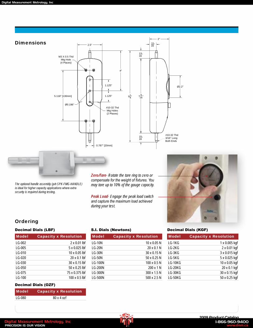
Dimensions
Model Capacity x Resolution
LG-1KG 1 x 0.005 kgf LG-2KG 2 x 0.01 kgf LG-3KG 3 x 0.015 kgf LG-5KG 5 x 0.025 kgf LG-10KG 10 x 0.05 kgf LG-20KG 20 x 0.1 kgf LG-30KG 30 x 0.15 kgf LG-50KG 50 x 0.25 kgf
Decimal Dials (KGF)
Model Capacity x Resolution
LG-080 80 x 4 ozf
Decimal Dials (OZF)
Ordering
Model Capacity x Resolution
LG-002 2 x 0.01 lbf LG-005 5 x 0.025 lbf LG-010 10 x 0.05 lbf LG-020 20 x 0.1 lbf LG-030 30 x 0.15 lbf LG-050 50 x 0.25 lbf LG-075 75 x 0.375 lbf LG-100 100 x 0.5 lbf
Decimal Dials (LBF)
Model Capacity x Resolution
LG-10N 10 x 0.05 N LG-20N 20 x 0.1 N LG-30N 30 x 0.15 N LG-50N 50 x 0.25 N LG-100N 100 x 0.5 N LG-200N 200 x 1 N LG-300N 300 x 1.5 N LG-500N 500 x 2.5 N
S.I. Dials (Newtons)
Peak Load- Engage the peak load switch and capture the maximum load achieved during your test.
The optional handle assembly (p/n SPK-FMG-HANDLE) is ideal for higher capacity applications where extra security is required during testing.
Zero/Tare- Rotate the tare ring to zero or compensate for the weight of fixtures. You may tare up to 10% of the gauge capacity.
Ø0.196"#10-32 ThdMtg Holes(2 Places)
2.5"
4"
5.118" [130mm]
0.787" [20mm]
914" 7 9
16"
2"
1316"
1516"
1116"
#10-32 Thd3/16" LongBoth Ends
Ø2.2"
M3 X 0.5 ThdMtg Hole(4 Places)
1.125"
1.125"
E96-328LG GAUGE SERIES
www.dmm.ca1-866-960-9400
PRECISION IS OUR VISIONDigital Measurement Metrology, Inc
TM
Digital Measurement Metrology, Inc
18 www.chatillon.com
DG Series High Capacity Mechanical Force Gauge
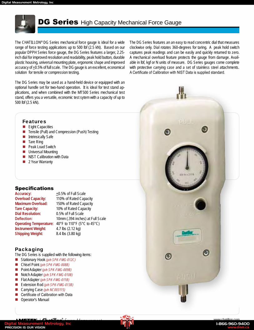
The CHATILLON® DG Series mechanical force gauge is ideal for a wide range of force testing applications up to 500 lbf (2.5 kN). Based on our popular DPPH Series force gauge, the DG Series features a larger, 2.25-inch dial for improved resolution and readability, peak hold button, durable plastic housing, universal mounting plate, ergonomic shape and improved accuracy of +0.5% of full scale. The DG gauge is an excellent, economical solution for tensile or compression testing.
The DG Series may be used as a hand-held device or equipped with an optional handle set for two-hand operation. It is ideal for test stand ap-plications, and when combined with the MT500 Series mechanical test stand, offers you a versatile, economic test sytem with a capacity of up to 500 lbf (2.5 kN).
The DG Series features an an easy to read concentric dial that measures clockwise only. Dial rotates 360-degrees for taring. A peak hold switch captures peak readings and can be easily and quickly returned to zero. A mechanical overload feature protects the gauge from damage. Avail-able in lbf, kgf or N units of measure. DG Series gauges come complete with protective carrying case and a set of stainless steel attachments. A Certificate of Calibration with NIST Data is supplied standard.
Featuresn Eight Capacitiesn Tensile (Pull) and Compression (Push) Testingn Intrinsically Safen Tare Ringn Peak Load Switchn Universal Mountingn NIST Calibration with Datan 2 Year Warranty
SpecificationsAccuracy: +0.5% of Full ScaleOverload Capacity: 110% of Rated CapacityMaximum Overload: 150% of Rated Capacity Tare Capacity: 10% of Rated CapacityDial Resolution: 0.5% of Full ScaleDeflection: 10mm (.394 inches) at Full ScaleOperating Temperature: 40°F to 110°F (5°C to 45°C)Instrument Weight: 4.7 lbs (2.12 kg)Shipping Weight: 8.4 lbs (3.80 kg)
PackagingThe DG Series is supplied with the following items:n Stationary Hook (p/n SPK-FMG-012C)n Chisel Point (p/n SPK-FMG-008B)n Point Adapter (p/n SPK-FMG-009B)n Notch Adapter (p/n SPK-FMG-010B)n Flat Adapter (p/n SPK-FMG-011B)n Extension Rod (p/n SPK-FMG-013B)n Carrying Case (p/n NC003115)n Certificate of Calibration with Datan Operator’s Manual
www.dmm.ca1-866-960-9400
PRECISION IS OUR VISIONDigital Measurement Metrology, Inc
TM
Digital Measurement Metrology, Inc
19 2009 Product Catalog
Ordering
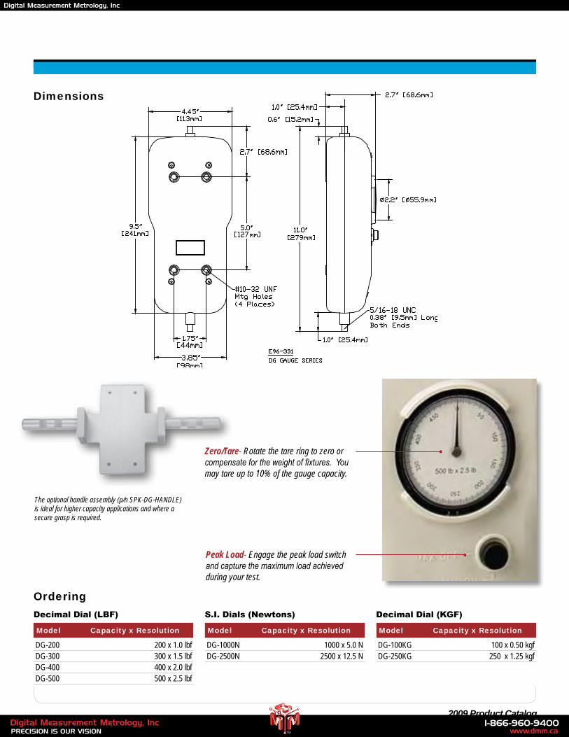
Model Capacity x Resolution
DG-200 200 x 1.0 lbf DG-300 300 x 1.5 lbf DG-400 400 x 2.0 lbf DG-500 500 x 2.5 lbf
Decimal Dial (LBF) Decimal Dial (KGF)S.I. Dials (Newtons)
DG-100KG 100 x 0.50 kgf DG-250KG 250 x 1.25 kgf
DG-1000N 1000 x 5.0 N DG-2500N 2500 x 12.5 N
Model Capacity x Resolution Model Capacity x Resolution
Peak Load- Engage the peak load switch and capture the maximum load achieved during your test.
The optional handle assembly (p/n SPK-DG-HANDLE) is ideal for higher capacity applications and where a secure grasp is required.
Zero/Tare- Rotate the tare ring to zero or compensate for the weight of fixtures. You may tare up to 10% of the gauge capacity.
Dimensions
www.dmm.ca1-866-960-9400
PRECISION IS OUR VISIONDigital Measurement Metrology, Inc
TM
Digital Measurement Metrology, Inc
20 www.chatillon.com
LTCM-100 Series Motorized Tester (110 lbf, 500 N)
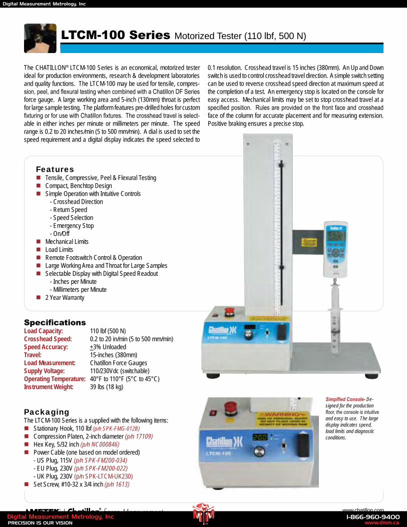
The CHATILLON® LTCM-100 Series is an economical, motorized tester ideal for production environments, research & development laboratories and quality functions. The LTCM-100 may be used for tensile, compres-sion, peel, and flexural testing when combined with a Chatillon DF Series force gauge. A large working area and 5-inch (130mm) throat is perfect for large sample testing. The platform features pre-drilled holes for custom fixturing or for use with Chatillon fixtures. The crosshead travel is select-able in either inches per minute or millimeters per minute. The speed range is 0.2 to 20 inches/min (5 to 500 mm/min). A dial is used to set the speed requirement and a digital display indicates the speed selected to
0.1 resolution. Crosshead travel is 15 inches (380mm). An Up and Down switch is used to control crosshead travel direction. A simple switch setting can be used to reverse crosshead speed direction at maximum speed at the completion of a test. An emergency stop is located on the console for easy access. Mechanical limits may be set to stop crosshead travel at a specified position. Rules are provided on the front face and crosshead face of the column for accurate placement and for measuring extension. Positive braking ensures a precise stop.
Featuresn Tensile, Compressive, Peel & Flexural Testingn Compact, Benchtop Designn Simple Operation with Intuitive Controls - Crosshead Direction - Return Speed - Speed Selection - Emergency Stop - On/Offn Mechanical Limits n Load Limitsn Remote Footswitch Control & Operationn Large Working Area and Throat for Large Samplesn Selectable Display with Digital Speed Readout - Inches per Minute - Millimeters per Minuten 2 Year Warranty
SpecificationsLoad Capacity: 110 lbf (500 N)Crosshead Speed: 0.2 to 20 in/min (5 to 500 mm/min) Speed Accuracy: +3% UnloadedTravel: 15-inches (380mm)Load Measurement: Chatillon Force GaugesSupply Voltage: 110/230Vdc (switchable)Operating Temperature: 40°F to 110°F (5°C to 45°C)Instrument Weight: 39 lbs (18 kg)
PackagingThe LTCM-100 Series is a supplied with the following items:n Stationary Hook, 110 lbf (p/n SPK-FMG-012B)n Compression Platen, 2-inch diameter (p/n 17109)n Hex Key, 5/32 inch (p/n NC000846)n Power Cable (one based on model ordered) - US Plug, 115V (p/n SPK-FM200-034) - EU Plug, 230V (p/n SPK-FM200-022) - UK Plug, 230V (p/n SPK-LTCM-UK230)n Set Screw, #10-32 x 3/4 inch (p/n 1613)
Simplfied Console- De-signed for the production floor, the console is intuitive and easy to use. The large display indicates speed, load limits and diagnostic conditions.
www.dmm.ca1-866-960-9400
PRECISION IS OUR VISIONDigital Measurement Metrology, Inc
TM
Digital Measurement Metrology, Inc
21 2009 Product Catalog
Dimensions
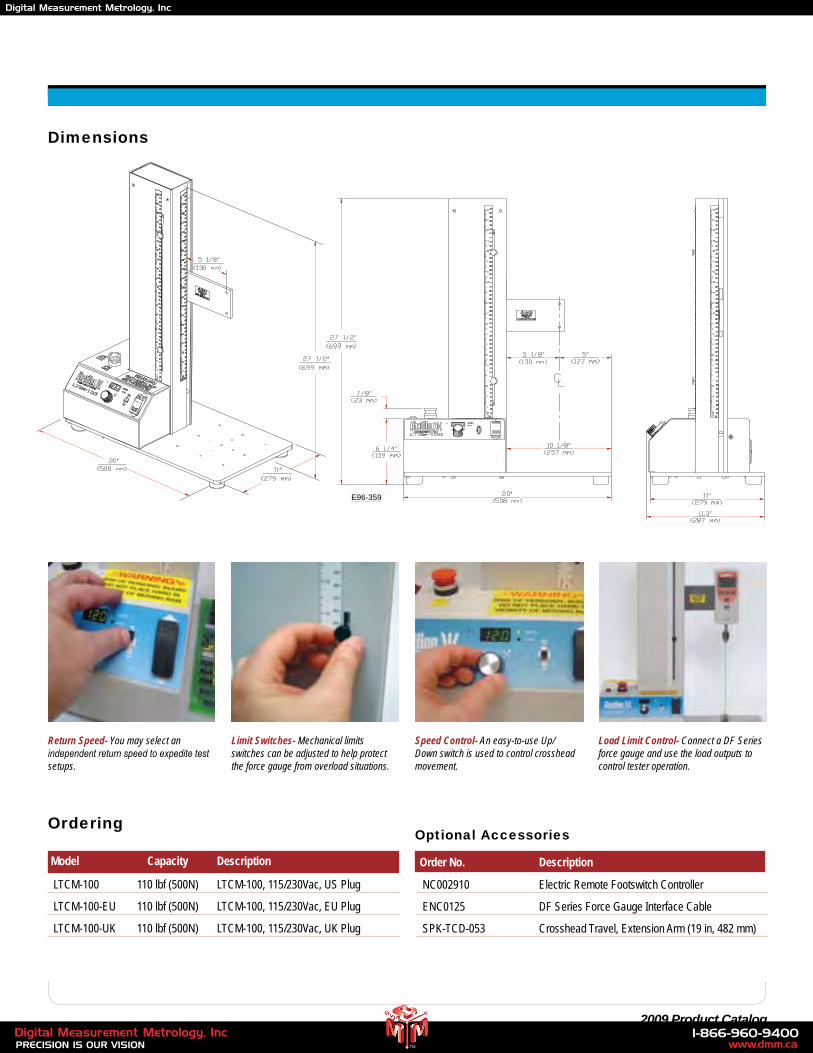
Return Speed- You may select an independent return speed to expedite test setups.
Speed Control- An easy-to-use Up/Down switch is used to control crosshead movement.
Load Limit Control- Connect a DF Series force gauge and use the load outputs to control tester operation.
Ordering
Model Capacity Description
LTCM-100 110 lbf (500N) LTCM-100, 115/230Vac, US Plug
LTCM-100-EU 110 lbf (500N) LTCM-100, 115/230Vac, EU Plug
LTCM-100-UK 110 lbf (500N) LTCM-100, 115/230Vac, UK Plug
Limit Switches- Mechanical limits switches can be adjusted to help protect the force gauge from overload situations.
E96-359
Optional Accessories
Order No. Description
NC002910 Electric Remote Footswitch Controller
ENC0125 DF Series Force Gauge Interface Cable
SPK-TCD-053 Crosshead Travel, Extension Arm (19 in, 482 mm)
www.dmm.ca1-866-960-9400
PRECISION IS OUR VISIONDigital Measurement Metrology, Inc
TM
Digital Measurement Metrology, Inc
22 www.chatillon.com
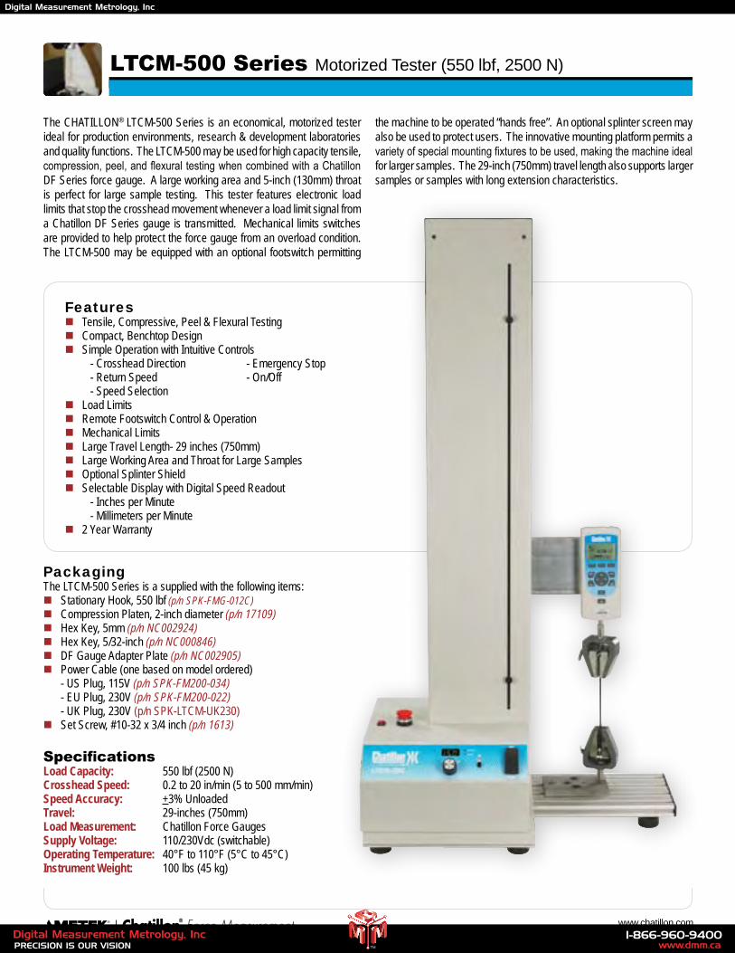
The CHATILLON® LTCM-500 Series is an economical, motorized tester ideal for production environments, research & development laboratories and quality functions. The LTCM-500 may be used for high capacity tensile, compression, peel, and flexural testing when combined with a Chatillon DF Series force gauge. A large working area and 5-inch (130mm) throat is perfect for large sample testing. This tester features electronic load limits that stop the crosshead movement whenever a load limit signal from a Chatillon DF Series gauge is transmitted. Mechanical limits switches are provided to help protect the force gauge from an overload condition. The LTCM-500 may be equipped with an optional footswitch permitting
the machine to be operated “hands free”. An optional splinter screen may also be used to protect users. The innovative mounting platform permits a variety of special mounting fixtures to be used, making the machine ideal for larger samples. The 29-inch (750mm) travel length also supports larger samples or samples with long extension characteristics.
Featuresn Tensile, Compressive, Peel & Flexural Testingn Compact, Benchtop Designn Simple Operation with Intuitive Controls - Crosshead Direction - Emergency Stop - Return Speed - On/Off - Speed Selectionn Load Limitsn Remote Footswitch Control & Operationn Mechanical Limitsn Large Travel Length- 29 inches (750mm)n Large Working Area and Throat for Large Samplesn Optional Splinter Shieldn Selectable Display with Digital Speed Readout - Inches per Minute - Millimeters per Minuten 2 Year Warranty
PackagingThe LTCM-500 Series is a supplied with the following items:n Stationary Hook, 550 lbf (p/n SPK-FMG-012C)n Compression Platen, 2-inch diameter (p/n 17109)n Hex Key, 5mm (p/n NC002924)n Hex Key, 5/32-inch (p/n NC000846)n DF Gauge Adapter Plate (p/n NC002905)n Power Cable (one based on model ordered) - US Plug, 115V (p/n SPK-FM200-034) - EU Plug, 230V (p/n SPK-FM200-022) - UK Plug, 230V (p/n SPK-LTCM-UK230)n Set Screw, #10-32 x 3/4 inch (p/n 1613)
SpecificationsLoad Capacity: 550 lbf (2500 N)Crosshead Speed: 0.2 to 20 in/min (5 to 500 mm/min) Speed Accuracy: +3% UnloadedTravel: 29-inches (750mm)Load Measurement: Chatillon Force GaugesSupply Voltage: 110/230Vdc (switchable)Operating Temperature: 40°F to 110°F (5°C to 45°C)Instrument Weight: 100 lbs (45 kg)
LTCM-500 Series Motorized Tester (550 lbf, 2500 N)
www.dmm.ca1-866-960-9400
PRECISION IS OUR VISIONDigital Measurement Metrology, Inc
TM
Digital Measurement Metrology, Inc
23 2009 Product Catalog
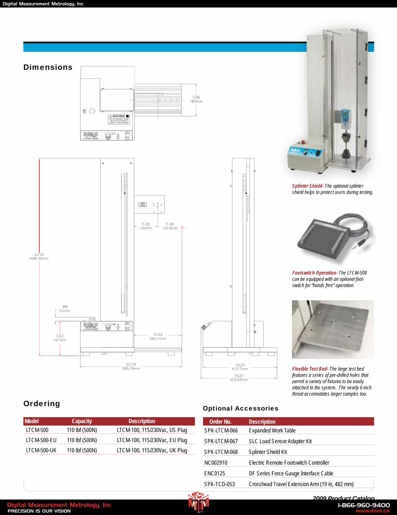
Footswitch Operation- The LTCM-500 can be equipped with an optional foot-switch for “hands free” operation.
Ordering
Model Capacity Description
LTCM-500 110 lbf (500N) LTCM-100, 115/230Vac, US Plug
LTCM-500-EU 110 lbf (500N) LTCM-100, 115/230Vac, EU Plug
LTCM-500-UK 110 lbf (500N) LTCM-100, 115/230Vac, UK Plug
Flexible Test Bed- The large test bed features a series of pre-drilled holes that permit a variety of fixtures to be easily attached to the system. The nearly 6-inch throat accomodates larger samples too.
Splinter Shield- The optional splinter shield helps to protect users during testing.
Optional Accessories
Order No. Description
SPK-LTCM-066 Expanded Work Table
SPK-LTCM-067 SLC Load Sensor Adapter Kit
SPK-LTCM-068 Splinter Shield Kit
NC002910 Electric Remote Footswitch Controller
ENC0125 DF Series Force Gauge Interface Cable
SPK-TCD-053 Crosshead Travel Extension Arm (19 in, 482 mm)
WARNING
Dimensions
www.dmm.ca1-866-960-9400
PRECISION IS OUR VISIONDigital Measurement Metrology, Inc
TM
Digital Measurement Metrology, Inc
24 www.chatillon.com
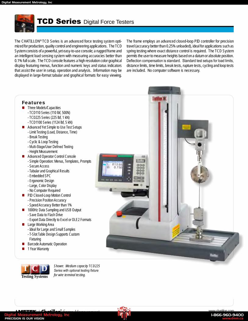
The CHATILLON® TCD Series is an advanced force testing system opti-mized for production, quality control and engineering applications. The TCD System consists of a powerful, yet easy-to-use console; a rugged frame and an intelligent load sensing system with measuring accuracies better than 0.1% full scale. The TCD console features a high resolution color graphical display featuring menus, function and numeric keys and status indicators that assist the user in setup, operation and analysis. Information may be displayed in large-format tabular and graphical formats for easy viewing.
The frame employs an advanced closed-loop PID controller for precision travel (accuracy better than 0.25% unloaded), ideal for applications such as spring testing where exact distance control is required. The TCD System permits the user to measure heights based on a datum or absolute position. Deflection compensation is standard. Standard test setups for load limits, distance limits, time limits, break tests, rupture tests, cycling and loop tests are included. No computer software is necessary.
Featuresn Three Models/Capacities - TCD110 Series (110 lbf, 500N) - TCD225 Series (225 lbf, 1 kN) - TCD1100 Series (1124 lbf, 5 kN)n Advanced Yet Simple to Use Test Setups - Limit Testing (Load, Distance, Time) - Break Testing - Cyclic & Loop Testing - Multi-Stage/User Defined Testing - Height Measurementn Advanced Operator Control Console - Simple Operation: Menus, Templates, Prompts - Secure Access - Tabular and Graphical Results - Embedded SPC - Ergonomic Design - Large, Color Display - No Computer Requiredn PID Closed-Loop Motion Control - Precision Position Accuracy - Speed Accuracy Better than 1%n 1000Hz Data Sampling and USB Output - Save Data to Flash Drive - Export Data Directly to Excel or OLE2 Formatsn Large Working Area - Ideal for Large and Small Samples - T-Slot Table Design Supports Custom Fixturingn Barcode Automatic Operationn 1 Year Warranty
TCD Series Digital Force Testers
T C DTesting Systems
Shown: Medium capacity TCD225 Series with optional testing fixture for wire terminal testing.
www.dmm.ca1-866-960-9400
PRECISION IS OUR VISIONDigital Measurement Metrology, Inc
TM
Digital Measurement Metrology, Inc
25 2009 Product CatalogThese specifications were developed in accordance with AMETEK’s standard procedures and are subject to change without notice.
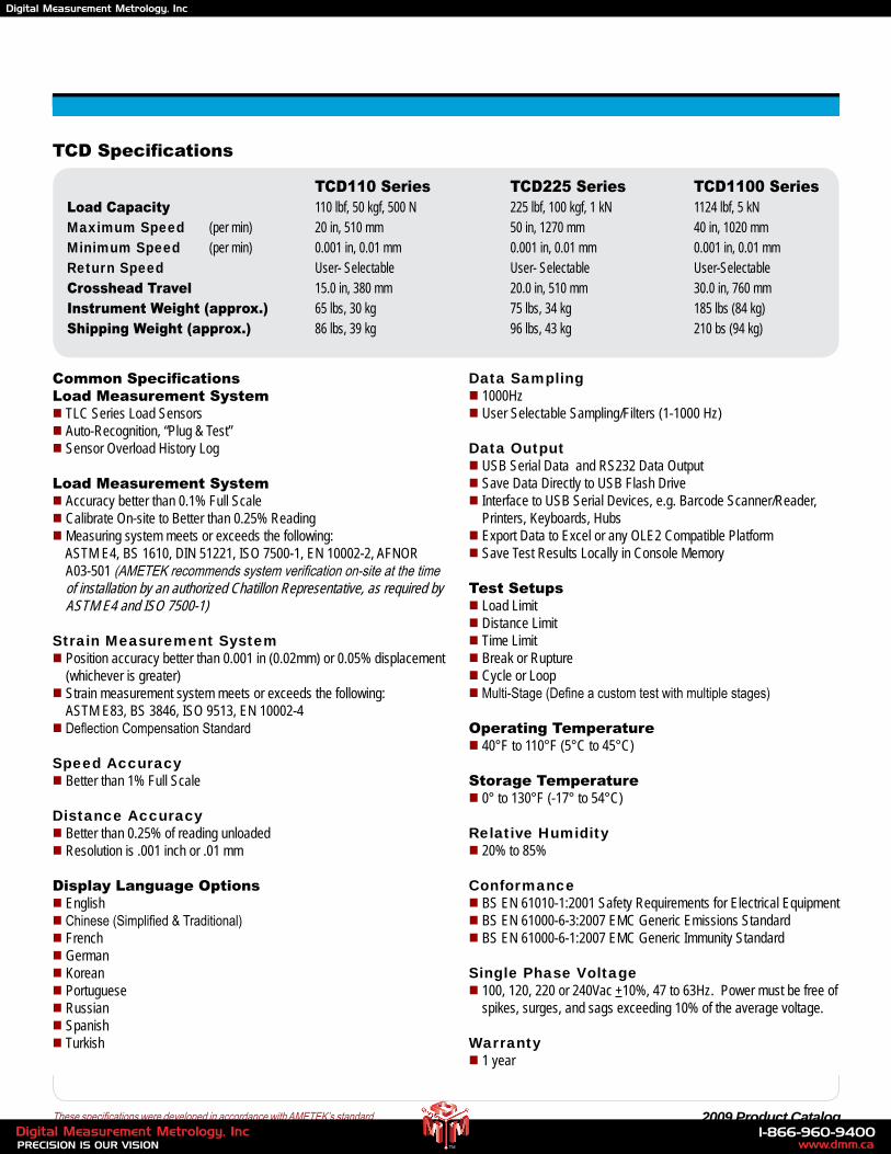
TCD Specifications
Common SpecificationsLoad Measurement Systemn TLC Series Load Sensors n Auto-Recognition, “Plug & Test”n Sensor Overload History Log
Load Measurement Systemn Accuracy better than 0.1% Full Scalen Calibrate On-site to Better than 0.25% Readingn Measuring system meets or exceeds the following: ASTM E4, BS 1610, DIN 51221, ISO 7500-1, EN 10002-2, AFNOR A03-501 (AMETEK recommends system verification on-site at the time of installation by an authorized Chatillon Representative, as required by ASTM E4 and ISO 7500-1)
Strain Measurement Systemn Position accuracy better than 0.001 in (0.02mm) or 0.05% displacement (whichever is greater) n Strain measurement system meets or exceeds the following: ASTM E83, BS 3846, ISO 9513, EN 10002-4n Deflection Compensation Standard
Speed Accuracyn Better than 1% Full Scale
Distance Accuracyn Better than 0.25% of reading unloadedn Resolution is .001 inch or .01 mm
Display Language Optionsn Englishn Chinese (Simplified & Traditional)n Frenchn Germann Koreann Portuguesen Russiann Spanishn Turkish
Data Samplingn 1000Hzn User Selectable Sampling/Filters (1-1000 Hz)
Data Outputn USB Serial Data and RS232 Data Output n Save Data Directly to USB Flash Drive n Interface to USB Serial Devices, e.g. Barcode Scanner/Reader,
Printers, Keyboards, Hubsn Export Data to Excel or any OLE2 Compatible Platform n Save Test Results Locally in Console Memory
Test Setupsn Load Limit n Distance Limitn Time Limitn Break or Rupturen Cycle or Loopn Multi-Stage (Define a custom test with multiple stages)
Operating Temperaturen 40°F to 110°F (5°C to 45°C)
Storage Temperaturen 0° to 130°F (-17° to 54°C)
Relative Humidityn 20% to 85%
Conformance n BS EN 61010-1:2001 Safety Requirements for Electrical Equipmentn BS EN 61000-6-3:2007 EMC Generic Emissions Standardn BS EN 61000-6-1:2007 EMC Generic Immunity Standard
Single Phase Voltagen 100, 120, 220 or 240Vac +10%, 47 to 63Hz. Power must be free of spikes, surges, and sags exceeding 10% of the average voltage.
Warrantyn 1 year
TCD110 Series TCD225 Series TCD1100 Series Load Capacity 110 lbf, 50 kgf, 500 N 225 lbf, 100 kgf, 1 kN 1124 lbf, 5 kN Maximum Speed (per min) 20 in, 510 mm 50 in, 1270 mm 40 in, 1020 mm Minimum Speed (per min) 0.001 in, 0.01 mm 0.001 in, 0.01 mm 0.001 in, 0.01 mm Return Speed User- Selectable User- Selectable User-Selectable Crosshead Travel 15.0 in, 380 mm 20.0 in, 510 mm 30.0 in, 760 mm Instrument Weight (approx.) 65 lbs, 30 kg 75 lbs, 34 kg 185 lbs (84 kg) Shipping Weight (approx.) 86 lbs, 39 kg 96 lbs, 43 kg 210 bs (94 kg)
www.dmm.ca1-866-960-9400
PRECISION IS OUR VISIONDigital Measurement Metrology, Inc
TM
Digital Measurement Metrology, Inc
26 www.chatillon.com
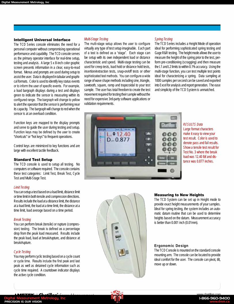
Intelligent Universal InterfaceThe TCD Series console eliminates the need for a personal computer without compromising operational performance and capability. The TCD console serves as the primary operator interface for real-time setup, testing and analysis. A large 5 x 8-inch color graphic screen presents information in a clear, easy-to-read format. Menus and prompts are used during setup to assist the user. Data is displayed in tabular and graphi-cal formats. Color is used to identify key status events or to inform the user of specific events. For example, a load bargraph displays during a test and displays green to indicate the sensor is measuring within its configured range. The bargraph will change to yellow to alert the operator that the sensor is performing near its capacity. The bargraph will change to red when the sensor is at an overload condition.
Function keys are mapped to the display prompts and serve to guide the user during testing and setup. Function keys may be defined by the user to create “shortcuts” or “hot keys” to frequent operations.
Control keys are minimized to key functions and are large with excellent tactile feedback. Standard Test SetupThe TCD console is used to setup all testing. No computers or software required. The console contains these test categories: Limit Test, Break Test, Cycle Test and Multi-Stage Test.
Limit TestingYou can setup a test based on a load limit, distance limit or time limit in both tensile and compression directions. Results include the load at a distance limit, the distance at a load limit, the load at a time limit, the distance at a time limit, load average based on a time period.
Break TestingYou can perform break (tensile) or rupture (compres-sion) testing. The break is defined as a percentage drop from the peak load measured. Results include the peak load, load at break/rupture, and distance at break/rupture.
Cycle TestingYou may perform cyclic testing based on a cycle count or cycle time. Results include the first peak and last peak as well as detained cycle information such as cycle time required. A countdown indicator displays the active cycle condition.
Multi-Stage TestingThe multi-stage setup allows the user to configure virtually any type of test setup imaginable. Each part of a test is defined as a “stage”. Each stage can be setup with its own independent load or distance characteristic and speed. Multi-stage testing can be used for creep tests, load hold or distance hold tests, insertion/extraction tests, snap-on/off tests or other sophisticated test methods. You can configure a wide range of wave shape methods including sine, triangle, sawtooth, square, ramp and trapezoidal to your test sample. The user has total freedom to create the test movement required for testing their sample without the need for expensive 3rd-party software applications or validation requirements.
Spring TestingThe TCD Series includes a Height Mode of operation ideal for performing sophisticated spring testing and Gage R&R testing. The height mode allows the user to measure the height of the spring prior to the test, per-form pre-conditioning (scragging) and then measure the L1 and L2 limits to within 0.1% accuracy. Using the multi-stage function, you can test multiple test points ideal for characterizing a spring. Data sampling at 1000 samples per second can be saved and exported into Excel for analysis and report generation. The ease and simplicity of the TCD System is unmatched.
Ergonomic DesignThe TCD Console is mounted on the standard console mounting arm. The console can be located to provide ideal comfort for the user. The console can pivot, tilt, move up or down.
RESULTS DataLarge format characters make it easy to view your test result. Color is used to denote pass and fail results. Show a tensile test result for Test No. 3 where the break load was 12.40 lbf and dis-tance was 0.877 inches.
Measuring to New HeightsThe TCD System can be set up in Height mode to provide exact height measurements of your samples. Ideal for spring testing, the system includes an auto-matic datum routine that can be used to determine heights based on the datum. Measurement accuracy is better than 0.001 inch (0.01mm).
www.dmm.ca1-866-960-9400
PRECISION IS OUR VISIONDigital Measurement Metrology, Inc
TM
Digital Measurement Metrology, Inc
27 2009 Product Catalog
Intuitive Setup MenusEach standard test setup within the TCD System contains easy-to-understand menus with test-specific attributes that assist the user in test setups. Common test attributes presented in an intuitive format and icons are displayed to provide the user with a graphical representation of their test setup. “Fill-in-the-blank” formats with a List of Values menu makes setup intui-tive, simple and fast. Safe guards are used to help ensure that only logical inputs are configured for a given test function.
All test setups are constructed graphically using Stages. The Stage Types are:
n Tensile Stage (Moves crosshead upward)n Compression Stage (Moves crosshead
downward)n Cycle Stage (Allows you to cycle multiple tensile
or compression Stages together)n Loop Stage (Similar to cycling, loop multiple
tensile or compression Stages and obtain results for each Stage)
n Hold Stage (Hold at a Load or a Distance for creep testing, relaxation testing, etc.)
n Zero Stage (Let’s you establish multiple zero positions during a test setup)
n Ask Stage (Place user comments and notations within a test setup)
There is no limit to the number of Stages that are used to define a test setup. Every Stage has an independent speed, load or distance characteristic that you define.
A list of coefficients are available for all test types. Select the coefficient you want to measure and obtain a result for. Up to ten (10) coefficients can be measured and displayed. You can rename the coefficient to make the result specific to your application.
Configuration in a “Flash”Once a TCD System is setup and its test or tests con-figured by a user, the entire configuration can be saved to a USB Flash Drive. The Flash Drive can be used to upload the configured tests to multiple TCD Systems in seconds. This eliminates the need for the user to have to perform an entire test setup procedure on multiple “like” testers. It also permits you to save the “master” file securely under the control of a supervisor.
Secure AccessThe TCD System provides you with the ultimate in security. The TCD console features two levels of user
access: supervisor and operator. Both levels may be password protected. The supervisor has complete system access, while an operator may be configured by the supervisor to have access to specified tests or test functions.
The TCD System can also be setup so that the system will only operate when the “required” USB Flash Drive with setup is installed. For example, you can install the test setup on a USB Flash Drive. The Flash Drive is required to be plugged in to the TCD System before the system can be operated. Without the required or correct USB Flash Drive, the system can be configured to be non-operational. Using an inexpensive flash drive with biometrics provides the ultimate in security.
Bar Code IntegrationThe use of bar code generators and readers can be integrated with your TCD System for security or to ensure
that the correct test setup is performed based on a part number, batch, user, etc. A bar code reader can be connected to the TCD System via a USB hub. The user can scan their security badge or a sample’s bar code to gain access to the specific test for that sample. Once the bar code is read by the reader, the TCD System displays the associated test setup and the authorized user is then allowed to perform the test.
Saving DataThe TCD System samples at a data rate of 1000 samples per second. This is especially useful when capturing transient events such as the precise break load of a brittle sample. Because the TCD System saves “true” raw data and not interpolated data like other systems, you have precise information to better characterize your material or component. Each test setup may be configured to sample at any sample rate from 1 to 1000 samples per second. Data may be saved to the USB Flash Drive for export to Excel or other OLE2 compatible file formats for analysis.
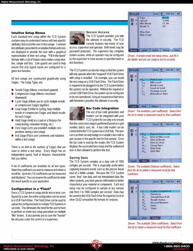
Shown: A simple break test setup menu. Just fill in the blanks and you are ready to test in seconds.
Shown: The available Load coefficients. Select from the list to obtain a measured result for that coefficient.
Shown: The available Distance coefficients. Select from the list to obtain a measured result for that coefficient.
Shown: The available Other coefficients. Select from the list to obtain a measured result for that coefficient.
www.dmm.ca1-866-960-9400
PRECISION IS OUR VISIONDigital Measurement Metrology, Inc
TM
Digital Measurement Metrology, Inc
28 www.chatillon.com
Comprehensive Result DisplaysOnce your test is completed, the TCD System will dis-play comprehensive results based on the coefficients you asked for. You can change the size of the result, the order it appears on the display, you can even cre-ate multiple screens for your results so that primary results are distinguished from secondary results.
Create Tolerances for Your ResultsDisplay results data in a small format showing toler-ance (pass/fail) limits. Example shows limits set at 5.00 lbf and 10.00 lbf. Actual break load was outside the limits, therefore the result is displayed in red indicating a failed test.
Graph Your ResultsLoad results data may be graphed based on time and distance. The number of data points that are used to draw the graph are set by the user. Up to 1000 data points may be configured. The navigation keys can be used to display a cross hair. Move the cross hair to view the precise measurement for each data points that was configured. You may output the data points directly into Excel for analysis or to create a more defined graph in a variety of formats.
Embedded SPC CalculationsSelecting the STATS soft key shows the statistical results for the test for each coefficient. This display shows the load value (peak load for stage No. 1). The Maximum, Minimum, Range, Average (Mean), Standard Deviation and COV are calculated.
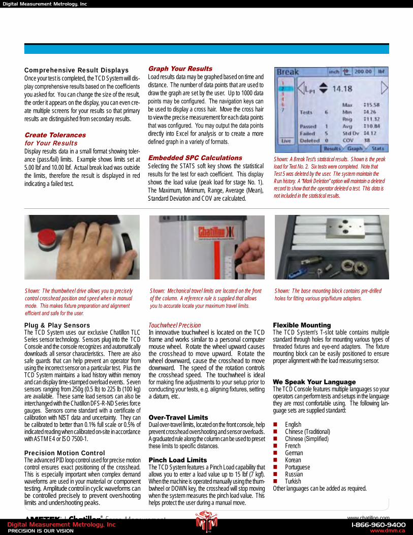
Shown: A Break Test’s statistical results. Shown is the peak load for Test No. 2. Six tests were completed. Note that Test 5 was deleted by the user. The system maintain the Run history. A “Mark Deletion” option will maintain a deleted record to show that the operator deleted a test. This data is not included in the statistical results.
Plug & Play SensorsThe TCD System uses our exclusive Chatillon TLC Series sensor technology. Sensors plug into the TCD Console and the console recognizes and automatically downloads all sensor characteristics. There are also safe guards that can help prevent an operator from using the incorrect sensor on a particular test. Plus the TCD System maintains a load history within memory and can display time-stamped overload events. Seven sensors ranging from 250g (0.5 lb) to 225 lb (100 kg) are available. These same load sensors can also be interchanged with the Chatillon DFS-R-ND Series force gauges. Sensors come standard with a certificate of calibration with NIST data and uncertainty. They can be calibrated to better than 0.1% full scale or 0.5% of indicated reading when calibrated on-site in accordance with ASTM E4 or ISO 7500-1.
Precision Motion ControlThe advanced PID loop control used for precise motion control ensures exact positioning of the crosshead. This is especially important when complex demand waveforms are used in your material or component testing. Amplitude control in cyclic waveforms can be controlled precisely to prevent overshooting limits and undershooting peaks.
Touchwheel PrecisionIn innovative touchwheel is located on the TCD frame and works similar to a personal computer mouse wheel. Rotate the wheel upward causes the crosshead to move upward. Rotate the wheel downward, cause the crosshead to move downward. The speed of the rotation controls the crosshead speed. The touchwheel is ideal for making fine adjustments to your setup prior to conducting your tests, e.g. aligning fixtures, setting a datum, etc.
Over-Travel LimitsDual over-travel limits, located on the front console, help prevent crosshead overshooting and sensor overloads. A graduated rule along the column can be used to preset these limits to specific distances.
Pinch Load LimitsThe TCD System features a Pinch Load capability that allows you to enter a load value up to 15 lbf (7 kgf). When the machine is operated manually using the thum-bwheel or DOWN key, the crosshead will stop moving when the system measures the pinch load value. This helps protect the user during a manual move.
Flexible MountingThe TCD System’s T-slot table contains multiple standard through holes for mounting various types of threaded fixtures and eye-end adapters. The fixture mounting block can be easily positioned to ensure proper alignment with the load measuring sensor.
We Speak Your LanguageThe TCD Console features multiple languages so your operators can perform tests and setups in the language they are most comfortable using. The following lan-guage sets are supplied standard:
n Englishn Chinese (Traditional)n Chinese (Simplified)n Frenchn Germann Koreann Portuguesen Russiann TurkishOther languages can be added as required.
Shown: The thumbwheel drive allows you to precisely control crosshead position and speed when in manual mode. This makes fixture preparation and alignment efficient and safe for the user.
Shown: The base mounting block contains pre-drilled holes for fitting various grip/fixture adapters.
Shown: Mechanical travel limits are located on the front of the column. A reference rule is supplied that allows you to accurate locate your maximum travel limits.
www.dmm.ca1-866-960-9400
PRECISION IS OUR VISIONDigital Measurement Metrology, Inc
TM
Digital Measurement Metrology, Inc
29 2009 Product Catalog
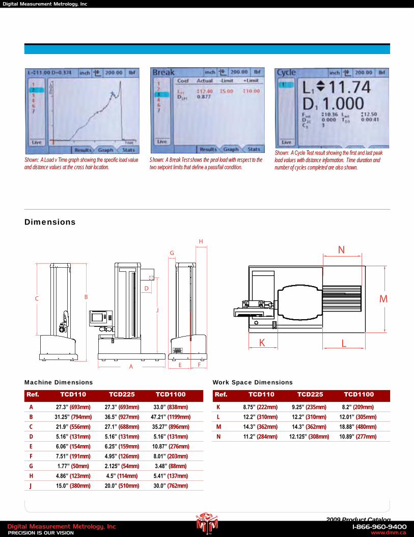
Shown: A Cycle Test result showing the first and last peak load values with distance information. Time duration and number of cycles completed are also shown.
Shown: A Load v Time graph showing the specific load value and distance values at the cross hair location.
Shown: A Break Test shows the peal load with respect to the two setpoint limits that define a pass/fail condition.
K L
M
A
BC
D
FE
H
G
N
J
K L
M
A
BC
D
FE
H
G
N
J
Dimensions
Ref. TCD110 TCD225 TCD1100
A 27.3” (693mm) 27.3” (693mm) 33.0” (838mm)
B 31.25” (794mm) 36.5” (927mm) 47.21” (1199mm)
C 21.9” (556mm) 27.1” (688mm) 35.27” (896mm)
D 5.16” (131mm) 5.16” (131mm) 5.16” (131mm)
E 6.06” (154mm) 6.25” (159mm) 10.87” (276mm)
F 7.51” (191mm) 4.95” (126mm) 8.01” (203mm)
G 1.77” (50mm) 2.125” (54mm) 3.48” (88mm)
H 4.86” (123mm) 4.5” (114mm) 5.41” (137mm)
J 15.0” (380mm) 20.0” (510mm) 30.0” (762mm)
Ref. TCD110 TCD225 TCD1100
K 8.75” (222mm) 9.25” (235mm) 8.2” (209mm)
L 12.2” (310mm) 12.2” (310mm) 12.01” (305mm)
M 14.3” (362mm) 14.3” (362mm) 18.88” (480mm)
N 11.2” (284mm) 12.125” (308mm) 10.89” (277mm)
Machine Dimensions Work Space Dimensions
www.dmm.ca1-866-960-9400
PRECISION IS OUR VISIONDigital Measurement Metrology, Inc
TM
Digital Measurement Metrology, Inc
30 www.chatillon.com
Model Description
TCD1100-X TCD1100 Series Frame with Console, No Load Cell
TCD1100-250G TCD1100 Series Frame, Console and TLC-250G Load Cell
TCD1100-0002 TCD1100 Series Frame, Console and TLC-0002 Load Cell
TCD1100-0005 TCD1100 Series Frame, Console and and TLC-0005 Load Cell
TCD1100-0010 TCD1100 Series Frame, Console and and TLC-0010 Load Cell
TCD1100-0025 TCD1100 Series Frame, Console and and TLC-0025 Load Cell
TCD1100-0050 TCD1100 Series Frame, Console and TLC-0050 Load Cell
TCD1100-0100 TCD1100 Series Frame, Console and and TLC-0100 Load Cell
TCD1100-0200 TCD1100 Series Frame, Console and TCL-0200 Load Cell
TCD1100-0500 TCD1100 Series Frame, Console and TLC-0500 Load Cell
TCD1100-1000 TCD1100 Series Frame, Console and and TLC-1000 Load Cell
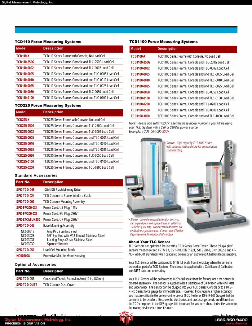
TCD1100 Force Measuring Systems
Note: Please add suffix “-230V” after the base model number if you will be using your TCD System with a 220 or 240Vac power source. Example: TCD1100-1000-230V.
TCD110 Force Measuring Systems
Model Description
TCD110-X TCD110 Series Frame with Console, No Load Cell
TCD110-250G TCD110 Series Frame, Console and TLC-250G Load Cell
TCD110-0002 TCD110 Series Frame, Console and TLC-0002 Load Cell
TCD110-0005 TCD110 Series Frame, Console and and TLC-0005 Load Cell
TCD110-0010 TCD110 Series Frame, Console and and TLC-0010 Load Cell
TCD110-0025 TCD110 Series Frame, Console and and TLC-0025 Load Cell
TCD110-0050 TCD110 Series Frame, Console and TLC-0050 Load Cell
TCD110-0100 TCD110 Series Frame, Console and and TLC-0100 Load Cell
TCD225 Force Measuring Systems
Model Description
TCD225-X TCD225 Series Frame with Console, No Load Cell
TCD225-250G TCD225 Series Frame, Console and TLC-250G Load Cell
TCD225-0002 TCD225 Series Frame, Console and TLC-0002 Load Cell
TCD225-0005 TCD225 Series Frame, Console and and TLC-0005 Load Cell
TCD225-0010 TCD225 Series Frame, Console and and TLC-0010 Load Cell
TCD225-0025 TCD225 Series Frame, Console and and TLC-0025 Load Cell
TCD225-0050 TCD225 Series Frame, Console and TLC-0050 Load Cell
TCD225-0100 TCD225 Series Frame, Console and and TLC-0100 Load Cell
TCD225-0200 TCD225 Series Frame, Console and TCL-0200 Load Cell
Standard Accessories
Part No. Description
SPK-TCD-048 1Gb USB Flash Memory Drive
SPK-TCD-024 TCD Console to Frame Interface Cable
SPK-TCD-002 TCD Console Mounting Assembly
SPK-FM200-034 Power Cord, US Plug, 115V
SPK-FM200-022 Power Cord, EU Plug, 230V1
SPK-LTCM-UK230 Power Cord, UK Plug, 230V1
SPK-TCD-042 Base Mounting Assembly
NC000612 Grip Pin, Stainless Steel NC003028 5/8” Eye End with M12 Thread, Stainless Steel NC003031 Locking Rings (2 ea), Stainless Steel NC003030 Spanner Wrench
SPK-TCD-051 Load Cell Mounting Block
NC003098 Protective Mat, for Motor Housing
Optional Accessories
Part No. Description
SPK-TCD-053 Crosshead Travel, Extension Arm (19 in, 482mm)
SPK-TCD-DUST TCD Console Dust Cover
Shown: Using the optional extension arm, you can expand your work space travel an additional 15-inches (380 mm). Greater travel distances are available as special orders. Contact your Chatillon Representative for additional information.
About Your TLC SensorTLC Sensors are optimized for use with a TCD Series Force Tester. These “plug & play” sensors meet or exceed ASTM E4, BS 1610, DIN 51221, ISO 7500-1, EN 10002-2 and AF-NOR A03-501 standards when calibrated on-site by an authorized Chatillon Representative.
Your TLC Sensor will be calibrated to 0.1% full scale from the factory when the sensor is ordered as part of a TCD System. The sensor is supplied with a Certificate of Calibration with NIST data and uncertainty.
Your TLC Sensor will be calibrated to 0.25% full scale from the factory when the sensor is ordered separately. The sensor is supplied with a Certificate of Calibration with NIST data and uncertainty. The sensor can be plugged into your TCD Series Console or to a DFS-R-ND Series force gauge for immediate use. However, if you require a higher accuracy, you must re-calibrate the sensor on the device (TCD Tester or DFS-R-ND Gauge) that the sensor is to be used on. Because the electronics and processing speeds are different on the TCD compared to the DFS gauge, it is important for you to re-characterize the sensor to the mating device each time it is used.
Shown: High capacity TCD1100 Series with optional testing fixture for compression spring testing.
www.dmm.ca1-866-960-9400
PRECISION IS OUR VISIONDigital Measurement Metrology, Inc
TM
Digital Measurement Metrology, Inc
31 2009 Product CatalogFor the authorized Chatillon Distributor or Manufacturer’s Representative near you, go to www.chatillon.com
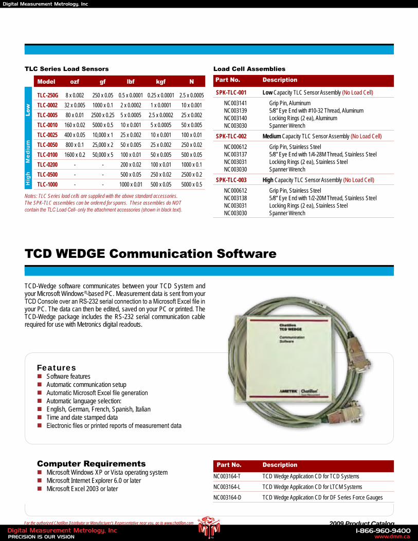
TLC Series Load Sensors
Model ozf gf lbf kgf N
TLC-250G 8 x 0.002 250 x 0.05 0.5 x 0.0001 0.25 x 0.0001 2.5 x 0.0005
TLC-0002 32 x 0.005 1000 x 0.1 2 x 0.0002 1 x 0.0001 10 x 0.001
TLC-0005 80 x 0.01 2500 x 0.25 5 x 0.0005 2.5 x 0.0002 25 x 0.002
TLC-0010 160 x 0.02 5000 x 0.5 10 x 0.001 5 x 0.0005 50 x 0.005
TLC-0025 400 x 0.05 10,000 x 1 25 x 0.002 10 x 0.001 100 x 0.01
TLC-0050 800 x 0.1 25,000 x 2 50 x 0.005 25 x 0.002 250 x 0.02
TLC-0100 1600 x 0.2 50,000 x 5 100 x 0.01 50 x 0.005 500 x 0.05
TLC-0200 - - 200 x 0.02 100 x 0.01 1000 x 0.1
TLC-0500 - - 500 x 0.05 250 x 0.02 2500 x 0.2
TLC-1000 - - 1000 x 0.01 500 x 0.05 5000 x 0.5
Load Cell Assemblies
Part No. Description
Part No. Description
SPK-TLC-001 Low Capacity TLC Sensor Assembly (No Load Cell)
NC003141 Grip Pin, Aluminum NC003139 5/8” Eye End with #10-32 Thread, Aluminum NC003140 Locking Rings (2 ea), Aluminum NC003030 Spanner Wrench
SPK-TLC-002 Medium Capacity TLC Sensor Assembly (No Load Cell)
NC000612 Grip Pin, Stainless Steel NC003137 5/8” Eye End with 1/4-28M Thread, Stainless Steel NC003031 Locking Rings (2 ea), Stainless Steel NC003030 Spanner Wrench
SPK-TLC-003 High Capacity TLC Sensor Assembly (No Load Cell)
NC000612 Grip Pin, Stainless Steel NC003138 5/8” Eye End with 1/2-20M Thread, Stainless Steel NC003031 Locking Rings (2 ea), Stainless Steel NC003030 Spanner Wrench
NC003164-T TCD Wedge Application CD for TCD Systems
NC003164-L TCD Wedge Application CD for LTCM Systems
NC003164-D TCD Wedge Application CD for DF Series Force Gauges
Me
diu
mH
igh
Low
Notes: TLC Series load cells are supplied with the above standard accessories. The SPK-TLC assemblies can be ordered for spares. These assemblies do NOT contain the TLC Load Cell- only the attachment accessories (shown in black text).
TCD WEDGE Communication Software
TCD-Wedge software communicates between your TCD System and your Microsoft Windows®-based PC. Measurement data is sent from your TCD Console over an RS-232 serial connection to a Microsoft Excel file in your PC. The data can then be edited, saved on your PC or printed. The TCD-Wedge package includes the RS-232 serial communication cable required for use with Metronics digital readouts.
Featuresn Software featuresn Automatic communication setupn Automatic Microsoft Excel file generationn Automatic language selection:n English, German, French, Spanish, Italiann Time and date stamped datan Electronic files or printed reports of measurement data
Computer Requirementsn Microsoft Windows XP or Vista operating systemn Microsoft Internet Explorer 6.0 or latern Microsoft Excel 2003 or later
www.dmm.ca1-866-960-9400
PRECISION IS OUR VISIONDigital Measurement Metrology, Inc
TM
Digital Measurement Metrology, Inc
32 www.chatillon.com
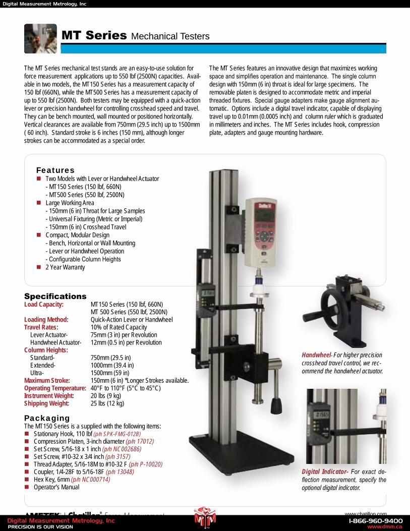
The MT Series mechanical test stands are an easy-to-use solution for force measurement applications up to 550 lbf (2500N) capacities. Avail-able in two models, the MT150 Series has a measurement capacity of 150 lbf (660N), while the MT500 Series has a measurement capacity of up to 550 lbf (2500N). Both testers may be equipped with a quick-action lever or precision handwheel for controlling crosshead speed and travel. They can be bench mounted, wall mounted or positioned horizontally. Vertical clearances are available from 750mm (29.5 inch) up to 1500mm ( 60 inch). Standard stroke is 6 inches (150 mm), although longer strokes can be accommodated as a special order.
The MT Series features an innovative design that maximizes working space and simplifies operation and maintenance. The single column design with 150mm (6 in) throat is ideal for large specimens. The removable platen is designed to accommodate metric and imperial threaded fixtures. Special gauge adapters make gauge alignment au-tomatic. Options include a digital travel indicator, capable of displaying travel up to 0.01mm (0.0005 inch) and column ruler which is graduated in millimeters and inches. The MT Series includes hook, compression plate, adapters and gauge mounting hardware.
MT Series Mechanical Testers
Digital Indicator- For exact de-flection measurement, specify the optional digital indicator.
Handwheel- For higher precision crosshead travel control, we rec-ommend the handwheel actuator.
Featuresn Two Models with Lever or Handwheel Actuator - MT150 Series (150 lbf, 660N) - MT500 Series (550 lbf, 2500N)n Large Working Area - 150mm (6 in) Throat for Large Samples - Universal Fixturing (Metric or Imperial) - 150mm (6 in) Crosshead Traveln Compact, Modular Design - Bench, Horizontal or Wall Mounting - Lever or Handwheel Operation - Configurable Column Heightsn 2 Year Warranty
SpecificationsLoad Capacity: MT150 Series (150 lbf, 660N) MT 500 Series (550 lbf, 2500N)Loading Method: Quick-Action Lever or Handwheel Travel Rates: 10% of Rated Capacity Lever Actuator- 75mm (3 in) per Revolution Handwheel Actuator- 12mm (0.5 in) per RevolutionColumn Heights: Standard- 750mm (29.5 in) Extended- 1000mm (39.4 in) Ultra- 1500mm (59 in)Maximum Stroke: 150mm (6 in) *Longer Strokes available.Operating Temperature: 40°F to 110°F (5°C to 45°C)Instrument Weight: 20 lbs (9 kg)Shipping Weight: 25 lbs (12 kg)
PackagingThe MT150 Series is a supplied with the following items:n Stationary Hook, 110 lbf (p/n SPK-FMG-012B)n Compression Platen, 3-inch diameter (p/n 17012)n Set Screw, 5/16-18 x 1 inch (p/n NC002686)n Set Screw, #10-32 x 3/4 inch (p/n 3157)n Thread Adapter, 5/16-18M to #10-32 F (p/n P-10020)n Coupler, 1/4-28F to 5/16-18F (p/n 13048)n Hex Key, 6mm (p/n NC000714)n Operator’s Manual
www.dmm.ca1-866-960-9400
PRECISION IS OUR VISIONDigital Measurement Metrology, Inc
TM
Digital Measurement Metrology, Inc
33 2009 Product Catalog
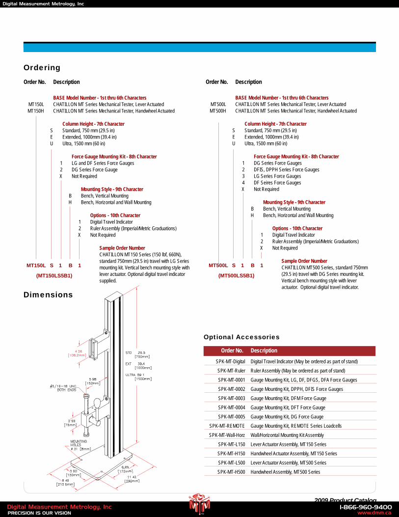
Ordering
Optional Accessories
Order No. Description
SPK-MT-Digital Digital Travel Indicator (May be ordered as part of stand)
SPK-MT-Ruler Ruler Assembly (May be ordered as part of stand)
SPK-MT-0001 Gauge Mounting Kit, LG, DF, DFGS, DFA Force Gauges
SPK-MT-0002 Gauge Mounting Kit, DPPH, DFIS Force Gauges
SPK-MT-0003 Gauge Mounting Kit, DFM Force Gauge
SPK-MT-0004 Gauge Mounting Kit, DFT Force Gauge
SPK-MT-0005 Gauge Mounting Kit, DG Force Gauge
SPK-MT-REMOTE Gauge Mounting Kit, REMOTE Series Loadcells
SPK-MT-Wall-Horz Wall/Horizontal Mounting Kit Assembly
SPK-MT-L150 Lever Actuator Assembly, MT150 Series
SPK-MT-H150 Handwheel Actuator Assembly, MT150 Series
SPK-MT-L500 Lever Actuator Assembly, MT500 Series
SPK-MT-H500 Handwheel Assembly, MT500 Series
Dimensions
Order No. Description
BASE Model Number - 1st thru 6th Characters MT150L CHATILLON MT Series Mechanical Tester, Lever Actuated MT150H CHATILLON MT Series Mechanical Tester, Handwheel Actuated
Column Height - 7th Character S Standard, 750 mm (29.5 in) E Extended, 1000mm (39.4 in) U Ultra, 1500 mm (60 in)
Force Gauge Mounting Kit - 8th Character 1 LG and DF Series Force Gauges 2 DG Series Force Gauge X Not Required
Mounting Style - 9th Character B Bench, Vertical Mounting H Bench, Horizontal and Wall Mounting
Options - 10th Character 1 Digital Travel Indicator 2 Ruler Assembly (Imperial/Metric Graduations) X Not Required
Sample Order Number CHATILLON MT150 Series (150 lbf, 660N),
standard 750mm (29.5 in) travel with LG Series mounting kit. Vertical bench mounting style with lever actuator. Optional digital travel indicator supplied.
(MT150LS5B1)
MT150L S 1 B 1
Order No. Description
BASE Model Number - 1st thru 6th Characters MT500L CHATILLON MT Series Mechanical Tester, Lever Actuated MT500H CHATILLON MT Series Mechanical Tester, Handwheel Actuated
Column Height - 7th Character S Standard, 750 mm (29.5 in) E Extended, 1000mm (39.4 in) U Ultra, 1500 mm (60 in)
Force Gauge Mounting Kit - 8th Character 1 DG Series Force Gauges 2 DFIS, DPPH Series Force Gauges 3 LG Series Force Gauges 4 DF Seires Force Gauges X Not Required
Mounting Style - 9th Character B Bench, Vertical Mounting H Bench, Horizontal and Wall Mounting
Options - 10th Character 1 Digital Travel Indicator 2 Ruler Assembly (Imperial/Metric Graduations) X Not Required
Sample Order Number CHATILLON MT500 Series, standard 750mm
(29.5 in) travel with DG Series mounting kit. Vertical bench mounting style with lever actuator. Optional digital travel indicator.
(MT500LS5B1)
MT500L S 1 B 1
www.dmm.ca1-866-960-9400
PRECISION IS OUR VISIONDigital Measurement Metrology, Inc
TM
Digital Measurement Metrology, Inc
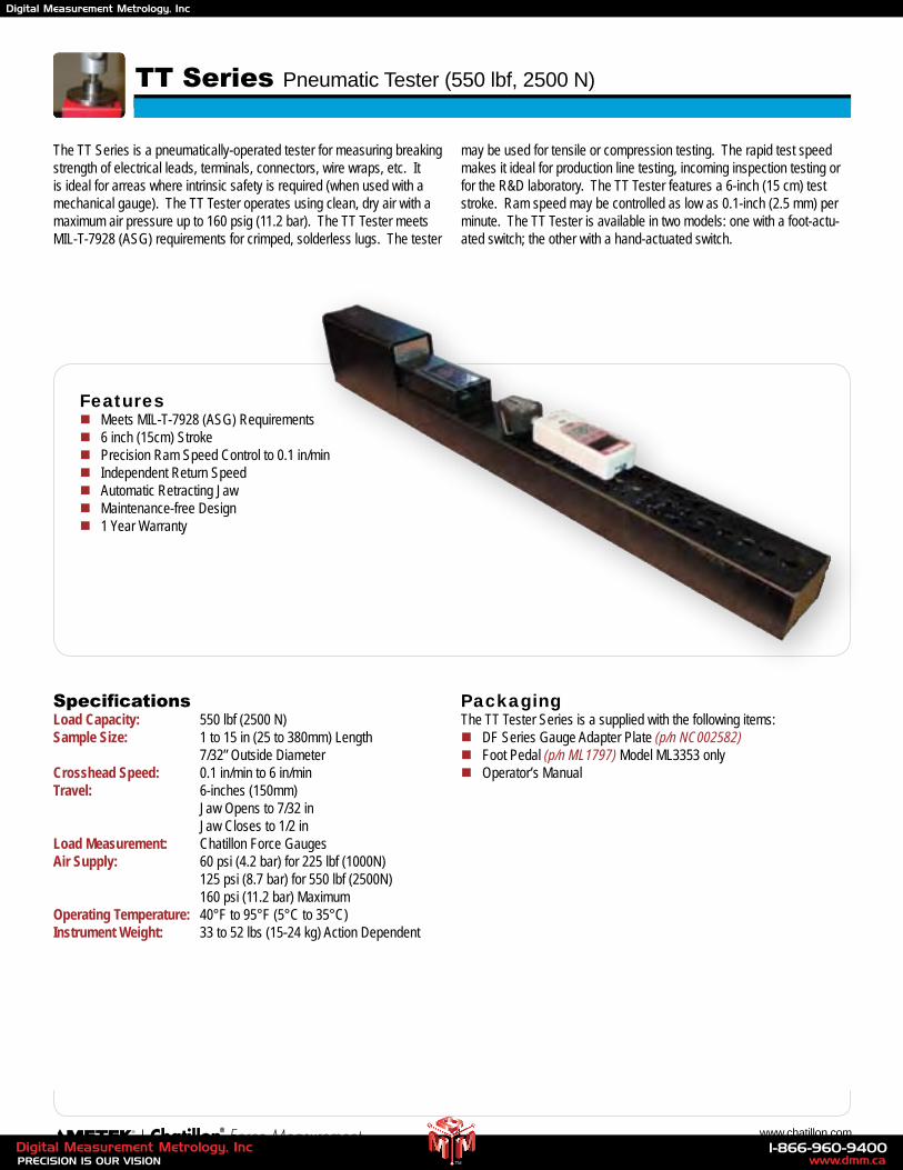
34 www.chatillon.com
The TT Series is a pneumatically-operated tester for measuring breaking strength of electrical leads, terminals, connectors, wire wraps, etc. It is ideal for arreas where intrinsic safety is required (when used with a mechanical gauge). The TT Tester operates using clean, dry air with a maximum air pressure up to 160 psig (11.2 bar). The TT Tester meets MIL-T-7928 (ASG) requirements for crimped, solderless lugs. The tester
may be used for tensile or compression testing. The rapid test speed makes it ideal for production line testing, incoming inspection testing or for the R&D laboratory. The TT Tester features a 6-inch (15 cm) test stroke. Ram speed may be controlled as low as 0.1-inch (2.5 mm) per minute. The TT Tester is available in two models: one with a foot-actu-ated switch; the other with a hand-actuated switch.
TT Series Pneumatic Tester (550 lbf, 2500 N)
Featuresn Meets MIL-T-7928 (ASG) Requirementsn 6 inch (15cm) Stroken Precision Ram Speed Control to 0.1 in/minn Independent Return Speedn Automatic Retracting Jawn Maintenance-free Designn 1 Year Warranty
PackagingThe TT Tester Series is a supplied with the following items:n DF Series Gauge Adapter Plate (p/n NC002582)n Foot Pedal (p/n ML1797) Model ML3353 onlyn Operator’s Manual
SpecificationsLoad Capacity: 550 lbf (2500 N)Sample Size: 1 to 15 in (25 to 380mm) Length 7/32” Outside DiameterCrosshead Speed: 0.1 in/min to 6 in/min Travel: 6-inches (150mm) Jaw Opens to 7/32 in Jaw Closes to 1/2 inLoad Measurement: Chatillon Force GaugesAir Supply: 60 psi (4.2 bar) for 225 lbf (1000N) 125 psi (8.7 bar) for 550 lbf (2500N) 160 psi (11.2 bar) MaximumOperating Temperature: 40°F to 95°F (5°C to 35°C)Instrument Weight: 33 to 52 lbs (15-24 kg) Action Dependent
www.dmm.ca1-866-960-9400
PRECISION IS OUR VISIONDigital Measurement Metrology, Inc
TM
Digital Measurement Metrology, Inc
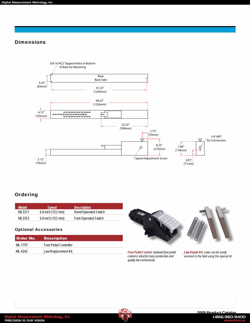
35 2009 Product Catalog
Ordering
Foot Pedal Control- Optional foot pedal control is ideal for busy production and quality lab evironments.
Jaw Repair Kit- Jaws can be easily serviced in the field using this special kit.
Model Speed Description ML3317 6.0-inch (152 mm) Hand-Operated Switch
ML3353 6.0-inch (152 mm) Foot-Operated Switch
Optional Accessories
Order No. Description
ML-1797 Foot Pedal Controller
ML-4242 Jaw Replacement Kit
4.12”(105mm)
3.25”(83mm)
3.12”(79mm)
23.22”(590mm)
2.75”(70mm)
8.25”(210mm)
7.00”(178mm)
2.81”(71mm)
48.25”(1226mm)
47.25”(1200mm)
1/4” NPTAir Connection
Speed Adjustment Screw
BaseBack Side
3/8-16 NC2 Tapped Holes in Bottomof Base for Mounting
Dimensions
www.dmm.ca1-866-960-9400
PRECISION IS OUR VISIONDigital Measurement Metrology, Inc
TM
Digital Measurement Metrology, Inc
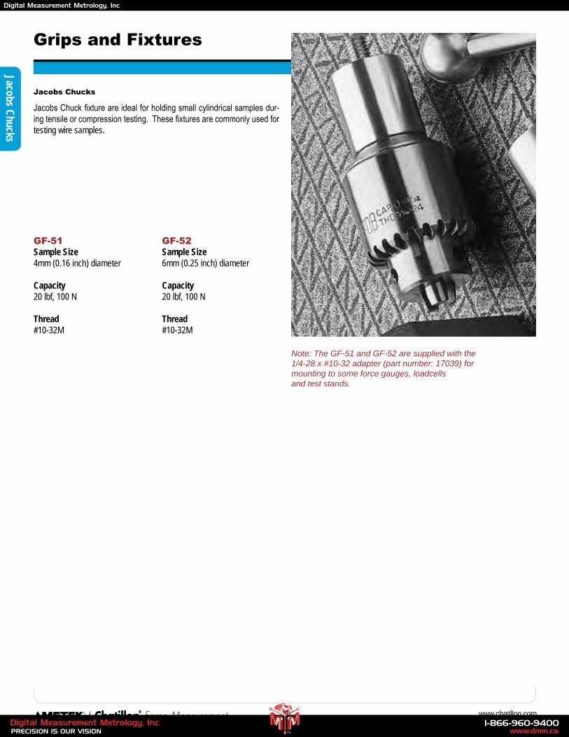
36 www.chatillon.com
Jacobs Chucks
Jacobs Chuck fixture are ideal for holding small cylindrical samples dur-ing tensile or compression testing. These fixtures are commonly used for testing wire samples.
GF-51Sample Size4mm (0.16 inch) diameter
Capacity20 lbf, 100 N
Thread#10-32M
GF-52Sample Size6mm (0.25 inch) diameter
Capacity20 lbf, 100 N
Thread#10-32M
Grips and Fixtures
Jacobs Chucks
Note: The GF-51 and GF-52 are supplied with the 1/4-28 x #10-32 adapter (part number: 17039) for mounting to some force gauges, loadcells and test stands.
www.dmm.ca1-866-960-9400
PRECISION IS OUR VISIONDigital Measurement Metrology, Inc
TM
Digital Measurement Metrology, Inc
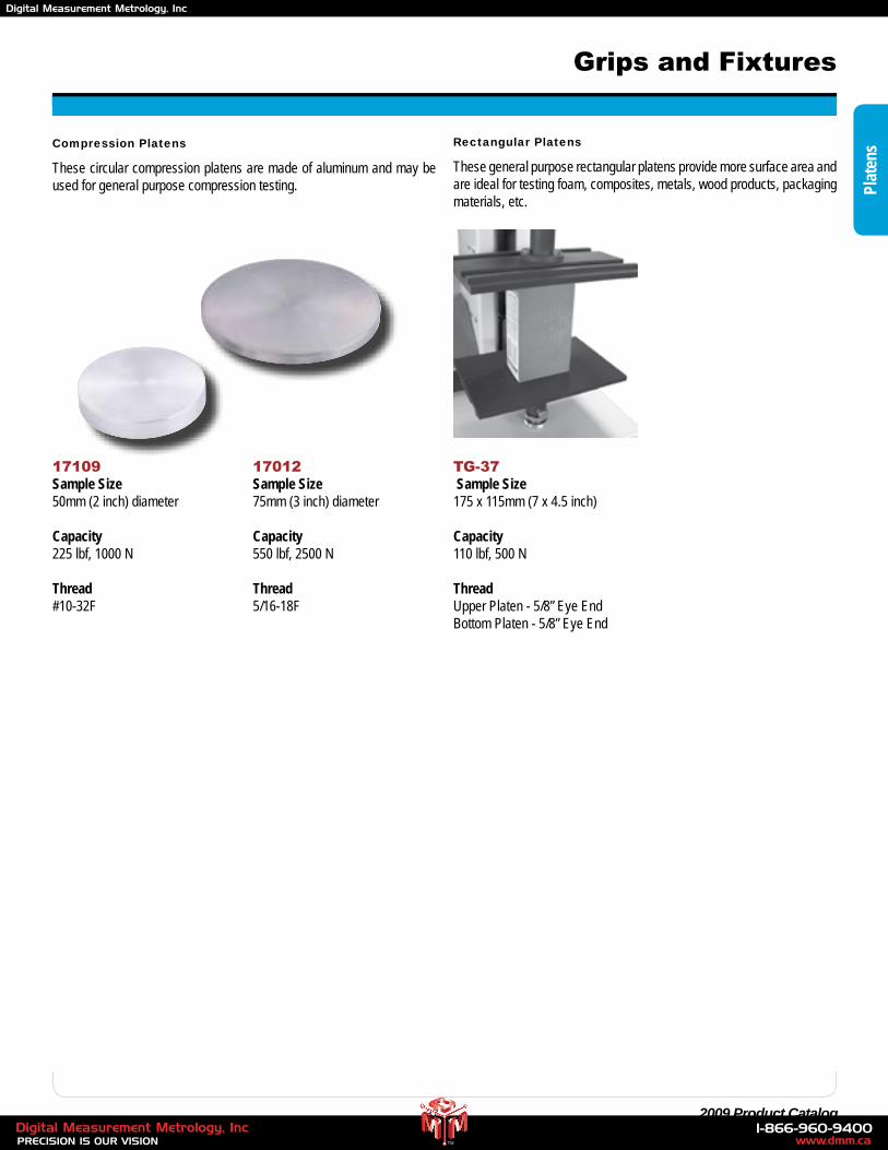
37 2009 Product Catalog
Compression Platens
These circular compression platens are made of aluminum and may be used for general purpose compression testing.
17109Sample Size50mm (2 inch) diameter
Capacity225 lbf, 1000 N
Thread#10-32F
17012Sample Size75mm (3 inch) diameter
Capacity550 lbf, 2500 N
Thread5/16-18F
Grips and Fixtures
Plat
ensRectangular Platens
These general purpose rectangular platens provide more surface area and are ideal for testing foam, composites, metals, wood products, packaging materials, etc.
TG-37 Sample Size175 x 115mm (7 x 4.5 inch)
Capacity110 lbf, 500 N
ThreadUpper Platen - 5/8” Eye EndBottom Platen - 5/8” Eye End
www.dmm.ca1-866-960-9400
PRECISION IS OUR VISIONDigital Measurement Metrology, Inc
TM
Digital Measurement Metrology, Inc
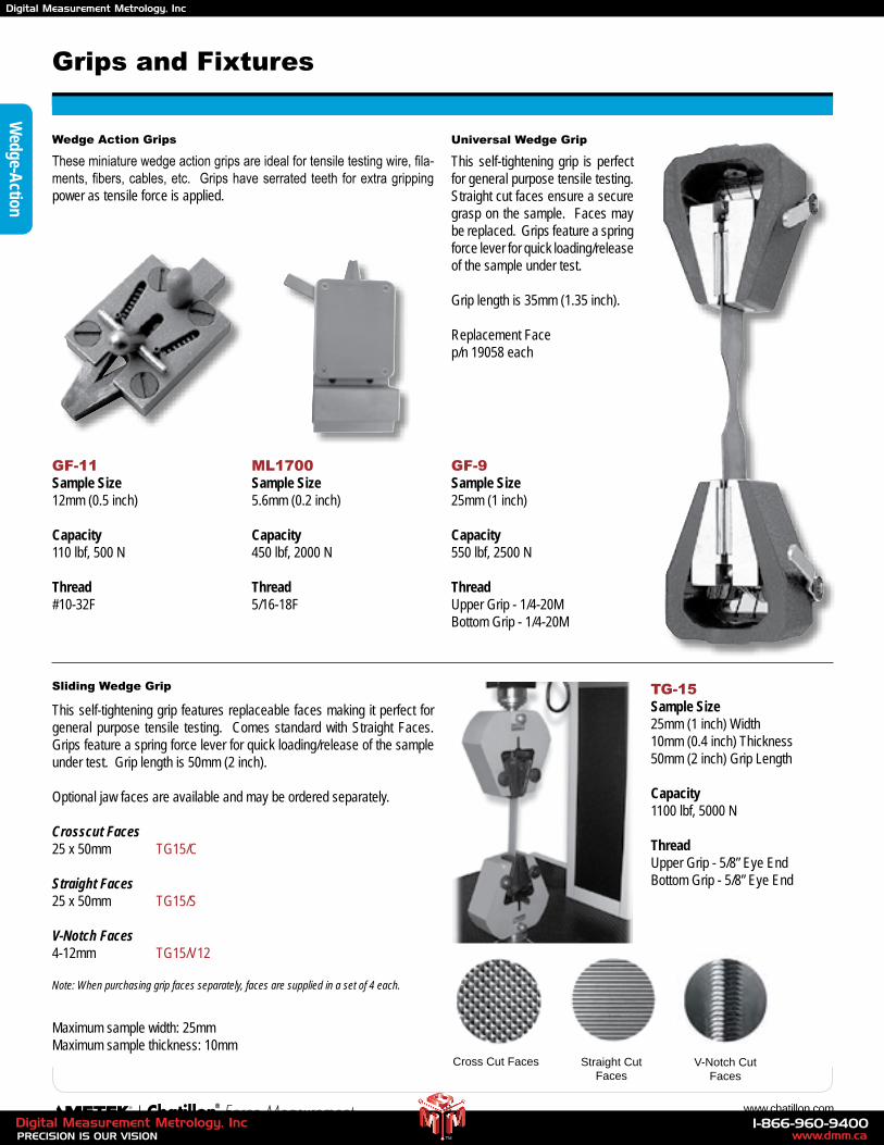
38 www.chatillon.com
Wedge Action Grips
These miniature wedge action grips are ideal for tensile testing wire, fila-ments, fibers, cables, etc. Grips have serrated teeth for extra gripping power as tensile force is applied.
GF-11Sample Size12mm (0.5 inch)
Capacity110 lbf, 500 N
Thread#10-32F
ML1700Sample Size5.6mm (0.2 inch)
Capacity450 lbf, 2000 N
Thread5/16-18F
GF-9Sample Size25mm (1 inch)
Capacity550 lbf, 2500 N
ThreadUpper Grip - 1/4-20MBottom Grip - 1/4-20M
Universal Wedge Grip
This self-tightening grip is perfect for general purpose tensile testing. Straight cut faces ensure a secure grasp on the sample. Faces may be replaced. Grips feature a spring force lever for quick loading/release of the sample under test.
Grip length is 35mm (1.35 inch).
Replacement Facep/n 19058 each
Grips and Fixtures
Sliding Wedge Grip TG-15Sample Size25mm (1 inch) Width10mm (0.4 inch) Thickness50mm (2 inch) Grip Length
Capacity1100 lbf, 5000 N
ThreadUpper Grip - 5/8” Eye EndBottom Grip - 5/8” Eye End
This self-tightening grip features replaceable faces making it perfect for general purpose tensile testing. Comes standard with Straight Faces. Grips feature a spring force lever for quick loading/release of the sample under test. Grip length is 50mm (2 inch).
Optional jaw faces are available and may be ordered separately.
Crosscut Faces25 x 50mm TG15/C
Straight Faces25 x 50mm TG15/S
V-Notch Faces4-12mm TG15/V12
Note: When purchasing grip faces separately, faces are supplied in a set of 4 each.
Wedge-A
ction
Maximum sample width: 25mmMaximum sample thickness: 10mm
Cross Cut Faces Straight Cut Faces
V-Notch Cut Faces
www.dmm.ca1-866-960-9400
PRECISION IS OUR VISIONDigital Measurement Metrology, Inc
TM
Digital Measurement Metrology, Inc
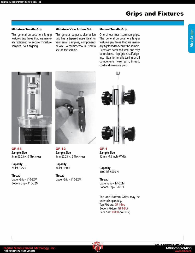
39 2009 Product Catalog
Grips and Fixtures
Vice
-Act
ionMiniature Tensile Grip
GF-53Sample Size5mm (0.2 inch) Thickness
Capacity28 lbf, 125 N
ThreadUpper Grip - #10-32MBottom Grip - #10-32M
This general purpose tensile grip features jaw faces that are manu-ally tightened to secure miniature samples. Self aligning.
Miniature Vice Action Grip
GF-12Sample Size5mm (0.2 inch) Thickness
Capacity34 lbf, 150 N
ThreadUpper Grip - #10-32M
This general purpose, vice action grip has a tapered nose ideal for very small samples, components or wire. A thumbscrew is used to secure the sample.
Manual Tensile Grip
GF-1Sample Size12mm (0.5 inch) Width
Capacity1100 lbf, 5000 N
ThreadUpper Grip - 1/4-20MBottom Grip - 3/8-16F
One of our most common grips. This general purpose tensile grip features jaw faces that are manu-ally tightened to secure the sample. Faces are hardened steel and may be replaced. Top grip is self align-ing. Ideal for tensile testing small components, wire, yarn, thread, cord and miniature parts.
Top and Bottom Grips may be ordered separately.Top Fixtrure: GF1-TopBottom Fixture: GF1-BotFace Set: 19058 (Set of 2)
www.dmm.ca1-866-960-9400
PRECISION IS OUR VISIONDigital Measurement Metrology, Inc
TM
Digital Measurement Metrology, Inc
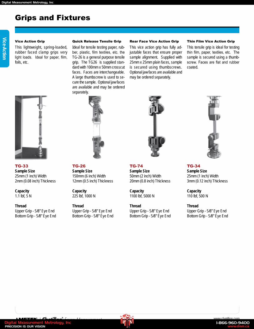
40 www.chatillon.com
Grips and Fixtures
Vice Action Grip
TG-33Sample Size25mm (1 inch) Width2mm (0.08 inch) Thickness
Capacity1.1 lbf, 5 N
ThreadUpper Grip - 5/8” Eye EndBottom Grip - 5/8” Eye End
This lightweight, spring-loaded, rubber faced clamp grips very light loads. Ideal for paper, film, foils, etc.
Quick Release Tensile Grip
TG-26Sample Size150mm (6 inch) Width12mm (0.5 inch) Thickness
Capacity225 lbf, 1000 N
ThreadUpper Grip - 5/8” Eye EndBottom Grip - 5/8” Eye End
Ideal for tensile testing paper, rub-ber, plastic, film textiles, etc. the TG-26 is a general purpose tensile grip. The TG26 is supplied stan-dard with 100mm x 50mm crosscut faces. Faces are interchangeable. A large thumbscrew is used to se-cure the sample. Optional jaw faces are available and may be ordered separately.
Thin Film Vice Action Grip
TG-34Sample Size25mm (1 inch) Width3mm (0.12 inch) Thickness
Capacity110 lbf, 500 N
ThreadUpper Grip - 5/8” Eye EndBottom Grip - 5/8” Eye End
This tensile grip is ideal for testing thin film, paper, textiles, etc. The sample is secured using a thumb-screw. Faces are flat and rubber coated.
Rear Face Vice Action Grip
TG-74Sample Size50mm (2 inch) Width20mm (0.8 inch) Thickness
Capacity1100 lbf, 5000 N
ThreadUpper Grip - 5/8” Eye EndBottom Grip - 5/8” Eye End
This vice action grip has fully ad-justable faces that ensure proper sample alignment. Supplied with 25mm x 25mm plain faces, sample is secured using thumbscrews. Optional jaw faces are available and may be ordered separately.
Vice-Action
www.dmm.ca1-866-960-9400
PRECISION IS OUR VISIONDigital Measurement Metrology, Inc
TM
Digital Measurement Metrology, Inc
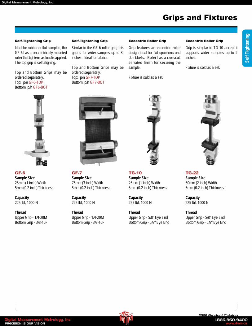
41 2009 Product Catalog
Grips and Fixtures
Self
Tigh
teni
ng
Eccentric Roller Grip
TG-10Sample Size25mm (1 inch) Width5mm (0.2 inch) Thickness
Capacity225 lbf, 1000 N
ThreadUpper Grip - 5/8” Eye EndBottom Grip - 5/8” Eye End
Grip features an eccentric roller design ideal for flat spcimens and dumbbells. Roller has a crosscut, serrated finish for securing the sample.
Fixture is sold as a set.
Eccentric Roller Grip
TG-22Sample Size50mm (2 inch) Width5mm (0.2 inch) Thickness
Capacity225 lbf, 1000 N
ThreadUpper Grip - 5/8” Eye EndBottom Grip - 5/8” Eye End
Grip is simplar to TG-10 accept it supports wider samples up to 2 inches.
Fixture is sold as a set.
Self-Tightening Grip
GF-6Sample Size25mm (1 inch) Width5mm (0.2 inch) Thickness
Capacity225 lbf, 1000 N
ThreadUpper Grip - 1/4-20MBottom Grip - 3/8-16F
Ideal for rubber or flat samples, the GF-6 has an eccentrically mounted roller that tightens as load is applied. The top grip is self aligning.
Top and Bottom Grips may be ordered separately.Top: p/n GF6-TOPBottom: p/n GF6-BOT
Self-Tightening Grip
GF-7Sample Size75mm (3 inch) Width5mm (0.2 inch) Thickness
Capacity225 lbf, 1000 N
ThreadUpper Grip - 1/4-20MBottom Grip - 3/8-16F
Similar to the GF-6 roller grip, this grip is for wider samples up to 3-inches. Ideal for fabrics.
Top and Bottom Grips may be ordered separately.Top: p/n GF7-TOPBottom: p/n GF7-BOT
www.dmm.ca1-866-960-9400
PRECISION IS OUR VISIONDigital Measurement Metrology, Inc
TM
Digital Measurement Metrology, Inc
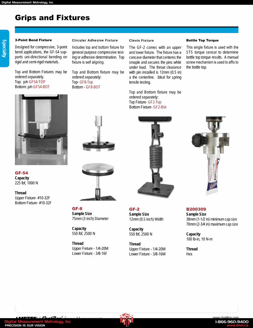
42 www.chatillon.com
Grips and Fixtures
3-Point Bend Fixture
GF-54Capacity225 lbf, 1000 N
ThreadUpper Fixture- #10-32FBottom Fixture- #10-32F
Designed for compressive, 3-point bend applications, the GF-54 sup-ports uni-directional bending on rigid and semi-rigid materials.
Top and Bottom Fixtures may be ordered separately.Top: p/n GF54-TOPBottom: p/n GF54-BOT
Specialty
Circular Adhesive Fixture
GF-8Sample Size75mm (3 inch) Diameter
Capacity550 lbf, 2500 N
ThreadUpper Fixture - 1/4-20MLower Fixture - 3/8-16F
Includes top and bottom fixture for general purpose compressive test-ing or adhesive determination. Top fixture is self aligning.
Top and Bottom fixture may be ordered separately:Top- GF8-TopBottom - GF8-BOT
Clevis Fixture
GF-2Sample Size12mm (0.5 inch) Width
Capacity550 lbf, 2500 N
ThreadUpper Fixture - 1/4-20MLower Fixture - 3/8-16M
The GF-2 comes with an upper and lower fixture. The fixture has a concave diameter that centeres the smaple and secures the pins while under load. The throat clearance with pin installed is 12mm (0.5 in) a the centerline. Ideal for spring tensile testing.
Top and Bottom fixture may be ordered separately:Top Fixture- GF2-TopBottom Fixture- GF2-Bot
Bottle Top Torque
B200309Sample Size38mm (1-1/2 in) minimum cap size70mm (2-3/4 in) maximum cap size
Capacity100 lb-in, 10 N-m
ThreadHex
This single fixture is used with the STS torque sensor to determine bottle top torque results. A manual screw mechanism is used to affix to the bottle top.
www.dmm.ca1-866-960-9400
PRECISION IS OUR VISIONDigital Measurement Metrology, Inc
TM
Digital Measurement Metrology, Inc
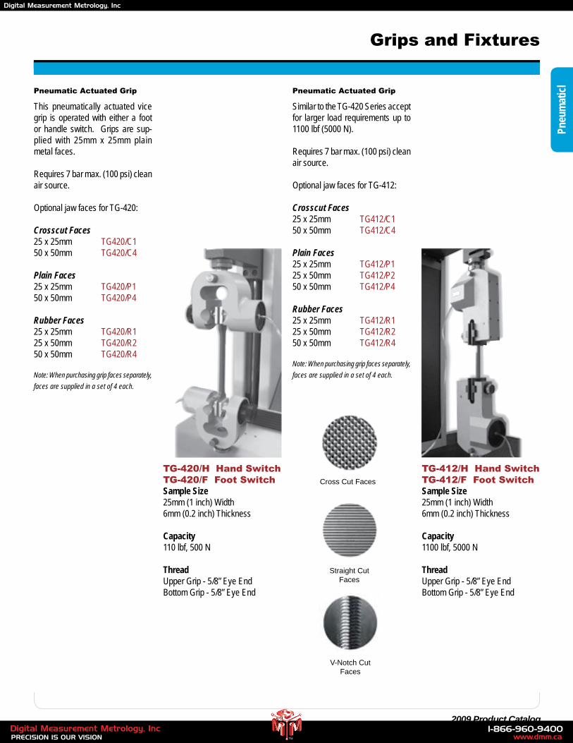
43 2009 Product Catalog
Grips and Fixtures
Pneu
mat
icl
Pneumatic Actuated Grip
TG-420/H Hand SwitchTG-420/F Foot SwitchSample Size25mm (1 inch) Width6mm (0.2 inch) Thickness
Capacity110 lbf, 500 N
ThreadUpper Grip - 5/8” Eye EndBottom Grip - 5/8” Eye End
This pneumatically actuated vice grip is operated with either a foot or handle switch. Grips are sup-plied with 25mm x 25mm plain metal faces.
Requires 7 bar max. (100 psi) clean air source.
Optional jaw faces for TG-420:
Crosscut Faces25 x 25mm TG420/C150 x 50mm TG420/C4
Plain Faces25 x 25mm TG420/P150 x 50mm TG420/P4
Rubber Faces25 x 25mm TG420/R125 x 50mm TG420/R250 x 50mm TG420/R4
Note: When purchasing grip faces separately,
faces are supplied in a set of 4 each.
Pneumatic Actuated Grip
TG-412/H Hand SwitchTG-412/F Foot SwitchSample Size25mm (1 inch) Width6mm (0.2 inch) Thickness
Capacity1100 lbf, 5000 N
ThreadUpper Grip - 5/8” Eye EndBottom Grip - 5/8” Eye End
Similar to the TG-420 Series accept for larger load requirements up to 1100 lbf (5000 N).
Requires 7 bar max. (100 psi) clean air source.
Optional jaw faces for TG-412:
Crosscut Faces25 x 25mm TG412/C150 x 50mm TG412/C4
Plain Faces25 x 25mm TG412/P125 x 50mm TG412/P250 x 50mm TG412/P4
Rubber Faces25 x 25mm TG412/R125 x 50mm TG412/R250 x 50mm TG412/R4
Note: When purchasing grip faces separately,
faces are supplied in a set of 4 each.
Cross Cut Faces
Straight Cut Faces
V-Notch Cut Faces
www.dmm.ca1-866-960-9400
PRECISION IS OUR VISIONDigital Measurement Metrology, Inc
TM
Digital Measurement Metrology, Inc
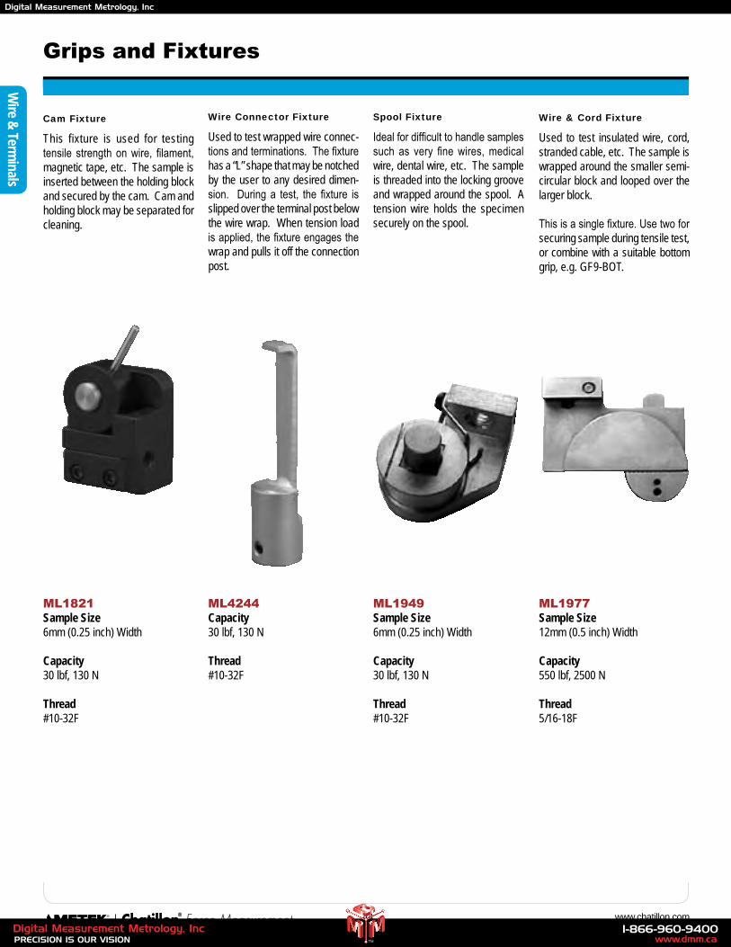
44 www.chatillon.com
Grips and Fixtures
Wire Connector Fixture
ML4244Capacity30 lbf, 130 N
Thread#10-32F
Used to test wrapped wire connec-tions and terminations. The fixture has a “L” shape that may be notched by the user to any desired dimen-sion. During a test, the fixture is slipped over the terminal post below the wire wrap. When tension load is applied, the fixture engages the wrap and pulls it off the connection post.
Cam Fixture
ML1821Sample Size6mm (0.25 inch) Width
Capacity30 lbf, 130 N
Thread#10-32F
This fixture is used for testing tensile strength on wire, filament, magnetic tape, etc. The sample is inserted between the holding block and secured by the cam. Cam and holding block may be separated for cleaning.
Spool Fixture
ML1949Sample Size6mm (0.25 inch) Width
Capacity30 lbf, 130 N
Thread#10-32F
Ideal for difficult to handle samples such as very fine wires, medical wire, dental wire, etc. The sample is threaded into the locking groove and wrapped around the spool. A tension wire holds the specimen securely on the spool.
Wire & Cord Fixture
ML1977Sample Size12mm (0.5 inch) Width
Capacity550 lbf, 2500 N
Thread5/16-18F
Used to test insulated wire, cord, stranded cable, etc. The sample is wrapped around the smaller semi-circular block and looped over the larger block.
This is a single fixture. Use two for securing sample during tensile test, or combine with a suitable bottom grip, e.g. GF9-BOT.
Wire &
Terminals
www.dmm.ca1-866-960-9400
PRECISION IS OUR VISIONDigital Measurement Metrology, Inc
TM
Digital Measurement Metrology, Inc
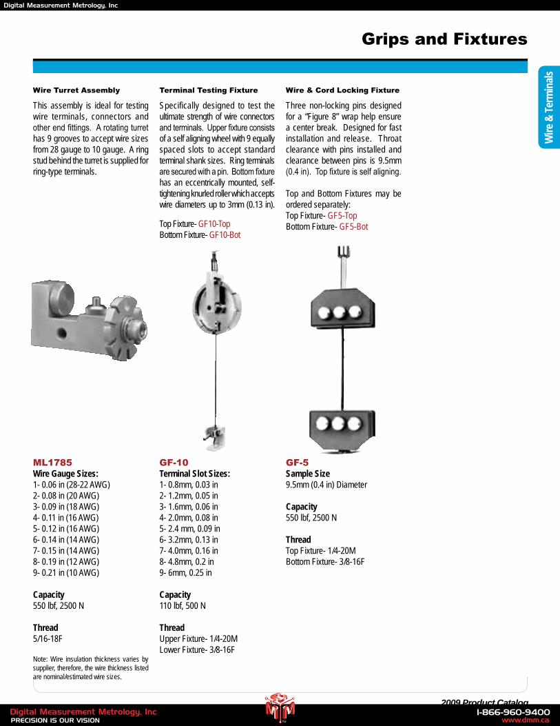
45 2009 Product Catalog
Grips and Fixtures
Wire Turret Assembly
ML1785Wire Gauge Sizes:1- 0.06 in (28-22 AWG)2- 0.08 in (20 AWG)3- 0.09 in (18 AWG)4- 0.11 in (16 AWG)5- 0.12 in (16 AWG)6- 0.14 in (14 AWG)7- 0.15 in (14 AWG)8- 0.19 in (12 AWG)9- 0.21 in (10 AWG)
Capacity550 lbf, 2500 N
Thread5/16-18F
Note: Wire insulation thickness varies by supplier, therefore, the wire thickness listed are nominal/estimated wire sizes.
This assembly is ideal for testing wire terminals, connectors and other end fittings. A rotating turret has 9 grooves to accept wire sizes from 28 gauge to 10 gauge. A ring stud behind the turret is supplied for ring-type terminals.
Terminal Testing Fixture
GF-10Terminal Slot Sizes:1- 0.8mm, 0.03 in2- 1.2mm, 0.05 in3- 1.6mm, 0.06 in4- 2.0mm, 0.08 in5- 2.4 mm, 0.09 in6- 3.2mm, 0.13 in7- 4.0mm, 0.16 in8- 4.8mm, 0.2 in9- 6mm, 0.25 in
Capacity110 lbf, 500 N
ThreadUpper Fixture- 1/4-20MLower Fixture- 3/8-16F
Specifically designed to test the ultimate strength of wire connectors and terminals. Upper fixture consists of a self aligning wheel with 9 equally spaced slots to accept standard terminal shank sizes. Ring terminals are secured with a pin. Bottom fixture has an eccentrically mounted, self-tightening knurled roller which accepts wire diameters up to 3mm (0.13 in).
Top Fixture- GF10-TopBottom Fixture- GF10-Bot
Wire & Cord Locking Fixture
GF-5Sample Size9.5mm (0.4 in) Diameter
Capacity550 lbf, 2500 N
ThreadTop Fixture- 1/4-20MBottom Fixture- 3/8-16F
Three non-locking pins designed for a “Figure 8” wrap help ensure a center break. Designed for fast installation and release. Throat clearance with pins installed and clearance between pins is 9.5mm (0.4 in). Top fixture is self aligning.
Top and Bottom Fixtures may be ordered separately:Top Fixture- GF5-TopBottom Fixture- GF5-Bot
Wire
& T
erm
inal
s
www.dmm.ca1-866-960-9400
PRECISION IS OUR VISIONDigital Measurement Metrology, Inc
TM
Digital Measurement Metrology, Inc
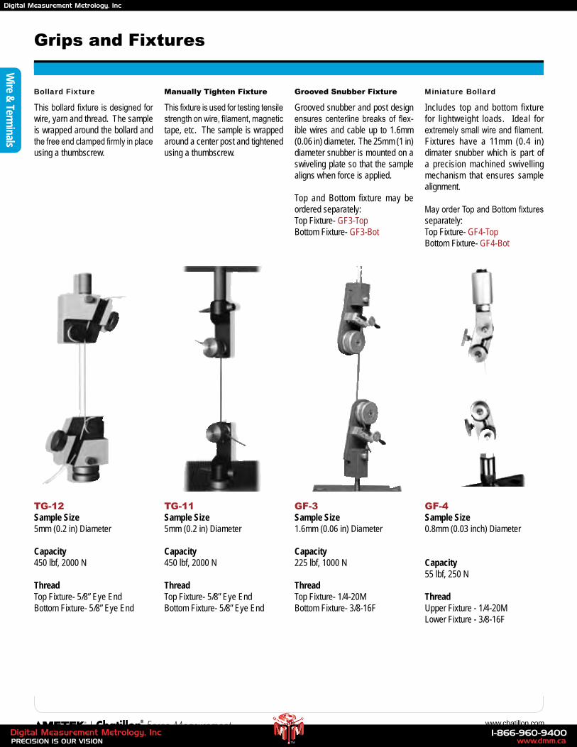
46 www.chatillon.com
Miniature Bollard
GF-4Sample Size0.8mm (0.03 inch) Diameter
Capacity55 lbf, 250 N
ThreadUpper Fixture - 1/4-20MLower Fixture - 3/8-16F
Includes top and bottom fixture for lightweight loads. Ideal for extremely small wire and filament. Fixtures have a 11mm (0.4 in) dimater snubber which is part of a precision machined swivelling mechanism that ensures sample alignment.
May order Top and Bottom fixtures separately:Top Fixture- GF4-TopBottom Fixture- GF4-Bot
Grips and Fixtures
Grooved Snubber Fixture
GF-3Sample Size1.6mm (0.06 in) Diameter
Capacity225 lbf, 1000 N
ThreadTop Fixture- 1/4-20MBottom Fixture- 3/8-16F
Grooved snubber and post design ensures centerline breaks of flex-ible wires and cable up to 1.6mm (0.06 in) diameter. The 25mm (1 in) diameter snubber is mounted on a swiveling plate so that the sample aligns when force is applied.
Top and Bottom fixture may be ordered separately:Top Fixture- GF3-TopBottom Fixture- GF3-Bot
Manually Tighten Fixture
TG-11Sample Size5mm (0.2 in) Diameter
Capacity450 lbf, 2000 N
ThreadTop Fixture- 5/8” Eye EndBottom Fixture- 5/8” Eye End
This fixture is used for testing tensile strength on wire, filament, magnetic tape, etc. The sample is wrapped around a center post and tightened using a thumbscrew.
Bollard Fixture
TG-12Sample Size5mm (0.2 in) Diameter
Capacity450 lbf, 2000 N
ThreadTop Fixture- 5/8” Eye EndBottom Fixture- 5/8” Eye End
This bollard fixture is designed for wire, yarn and thread. The sample is wrapped around the bollard and the free end clamped firmly in place using a thumbscrew.
Wire &
Terminals
www.dmm.ca1-866-960-9400
PRECISION IS OUR VISIONDigital Measurement Metrology, Inc
TM
Digital Measurement Metrology, Inc
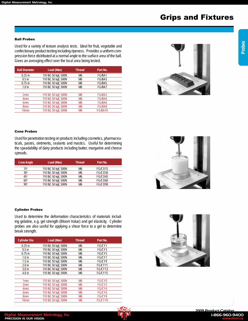
47 2009 Product Catalog
Cone Angle Load (Max) Thread Part No.
Prob
es
Grips and Fixtures
Ball Probes
Used for a variety of texture analysis tests. Ideal for fruit, vegetable and confectionary product testing including ripeness. Provides a uniform com-pression force distributed at a normal angle to the surface area of the ball. Gives an averaging effect over the local area being tested.
Ball Diameter Load (Max) Thread Part No. 0.25 in 110 lbf, 50 kgf, 500N M6 FG/BA1 0.5 in 110 lbf, 50 kgf, 500N M6 FG/BA3 0.75 in 110 lbf, 50 kgf, 500N M6 FG/BA5 1.0 in 110 lbf, 50 kgf, 500N M6 FG/BA7
2mm 110 lbf, 50 kgf, 500N M6 FG/BA2 4mm 110 lbf, 50 kgf, 500N M6 FG/BA4 6mm 110 lbf, 50 kgf, 500N M6 FG/BA6 8mm 110 lbf, 50 kgf, 500N M6 FG/BA8 10mm 110 lbf, 50 kgf, 500N M6 FG/BA10
Cone Probes
Used for penetration testing on products including cosmetics, pharmaceu-ticals, pastes, ointments, sealants and mastics. Useful for determining the speadability of dairy products including butter, margarine and cheese spreads.
15o 110 lbf, 50 kgf, 500N M6 FG/CO15 30o 110 lbf, 50 kgf, 500N M6 FG/CO30 45o 110 lbf, 50 kgf, 500N M6 FG/CO45 60o 110 lbf, 50 kgf, 500N M6 FG/CO60 90o 110 lbf, 50 kgf, 500N M6 FG/CO90
Cylinder Probes
Used to determine the deformation characteristics of materials includ-ing gelatine, e.g. gel strength (Bloom Value) and gel elasticity. Cylinder probes are also useful for applying a shear force to a gel to determine break strength.
Cylinder Dia Load (Max) Thread Part No. 0.25 in 110 lbf, 50 kgf, 500N M6 FG/CY1 0.5 in 110 lbf, 50 kgf, 500N M6 FG/CY3 0.75 in 110 lbf, 50 kgf, 500N M6 FG/CY5 1.0 in 110 lbf, 50 kgf, 500N M6 FG/CY7 1.5 in 110 lbf, 50 kgf, 500N M6 FG/CY9 2.0 in 110 lbf, 50 kgf, 500N M6 FG/CY11 3.0 in 110 lbf, 50 kgf, 500N M6 FG/CY13 4.0 in 110 lbf, 50 kgf, 500N M6 FG/CY15
1mm 110 lbf, 50 kgf, 500N M6 FG/CY0 2mm 110 lbf, 50 kgf, 500N M6 FG/CY2 4mm 110 lbf, 50 kgf, 500N M6 FG/CY4 6mm 110 lbf, 50 kgf, 500N M6 FG/CY6 8mm 110 lbf, 50 kgf, 500N M6 FG/CY8 10mm 110 lbf, 50 kgf, 500N M6 FG/CY10
www.dmm.ca1-866-960-9400
PRECISION IS OUR VISIONDigital Measurement Metrology, Inc
TM
Digital Measurement Metrology, Inc
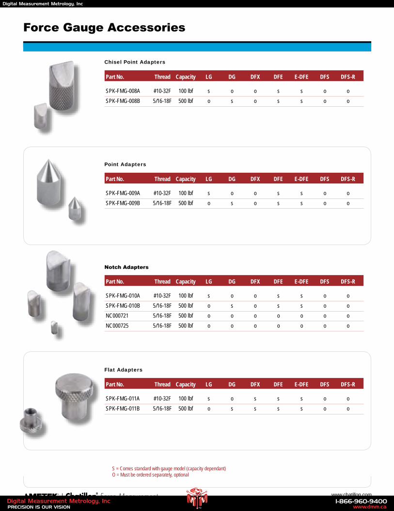
48 www.chatillon.com
Force Gauge Accessories
Chisel Point Adapters
Part No. Thread Capacity LG DG DFX DFE E-DFE DFS DFS-R
SPK-FMG-008A #10-32F 100 lbf s o o s s o o
SPK-FMG-008B 5/16-18F 500 lbf o s o s s o o
S = Comes standard with gauge model (capacity dependant) O = Must be ordered separately, optional
Point Adapters
Part No. Thread Capacity LG DG DFX DFE E-DFE DFS DFS-R
SPK-FMG-009A #10-32F 100 lbf s o o s s o o
SPK-FMG-009B 5/16-18F 500 lbf o s o s s o o
Notch Adapters
Part No. Thread Capacity LG DG DFX DFE E-DFE DFS DFS-R
SPK-FMG-010A #10-32F 100 lbf s o o s s o o
SPK-FMG-010B 5/16-18F 500 lbf o s o s s o o
NC000721 5/16-18F 500 lbf o o o o o o o
NC000725 5/16-18F 500 lbf o o o o o o o
Flat Adapters
Part No. Thread Capacity LG DG DFX DFE E-DFE DFS DFS-R
SPK-FMG-011A #10-32F 100 lbf s o s s s o o
SPK-FMG-011B 5/16-18F 500 lbf o s s s s o o
www.dmm.ca1-866-960-9400
PRECISION IS OUR VISIONDigital Measurement Metrology, Inc
TM
Digital Measurement Metrology, Inc
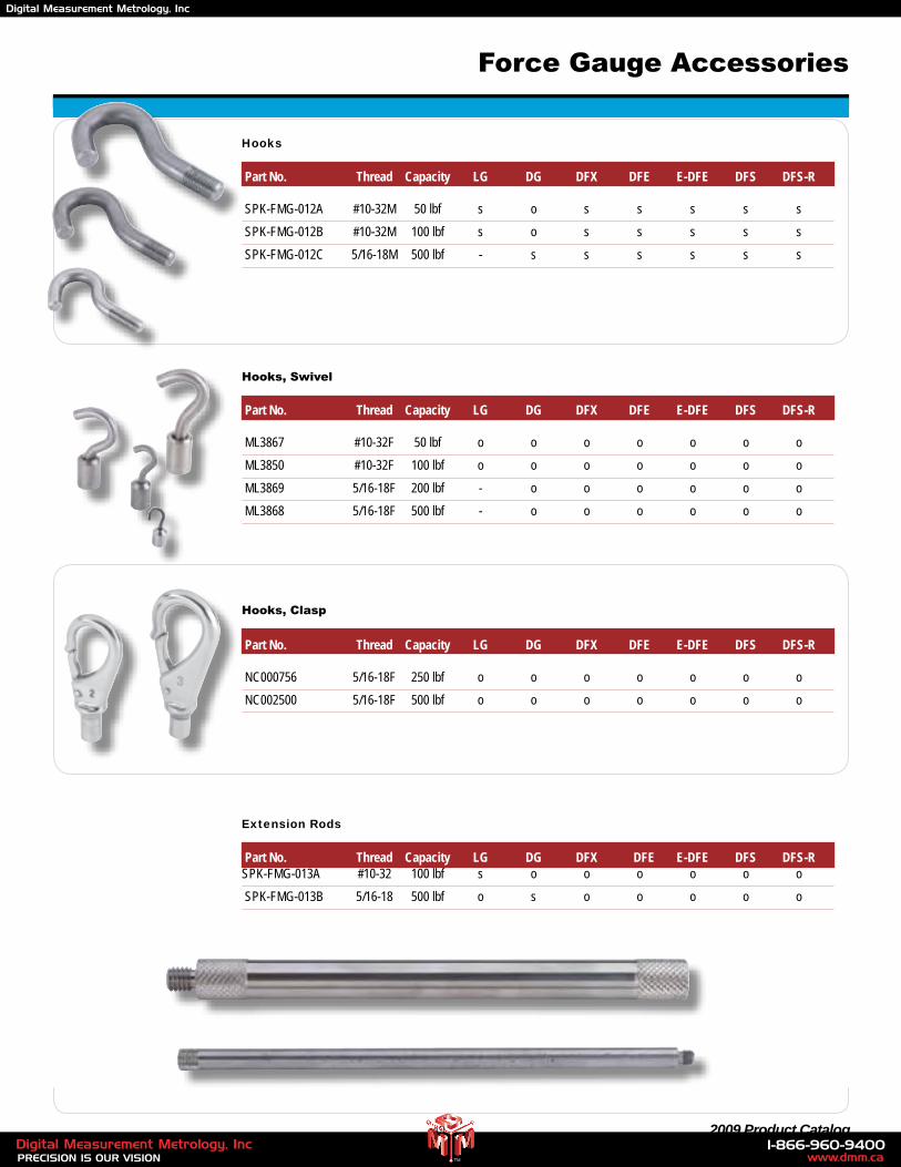
49 2009 Product Catalog
Hooks
Part No. Thread Capacity LG DG DFX DFE E-DFE DFS DFS-R
SPK-FMG-012A #10-32M 50 lbf s o s s s s s
SPK-FMG-012B #10-32M 100 lbf s o s s s s s
SPK-FMG-012C 5/16-18M 500 lbf - s s s s s s
Hooks, Swivel
Part No. Thread Capacity LG DG DFX DFE E-DFE DFS DFS-R
ML3867 #10-32F 50 lbf o o o o o o o
ML3850 #10-32F 100 lbf o o o o o o o
ML3869 5/16-18F 200 lbf - o o o o o o
ML3868 5/16-18F 500 lbf - o o o o o o
Hooks, Clasp
Part No. Thread Capacity LG DG DFX DFE E-DFE DFS DFS-R
NC000756 5/16-18F 250 lbf o o o o o o o
NC002500 5/16-18F 500 lbf o o o o o o o
Extension Rods
Part No. Thread Capacity LG DG DFX DFE E-DFE DFS DFS-RSPK-FMG-013A #10-32 100 lbf s o o o o o o
SPK-FMG-013B 5/16-18 500 lbf o s o o o o o
Force Gauge Accessories
www.dmm.ca1-866-960-9400
PRECISION IS OUR VISIONDigital Measurement Metrology, Inc
TM
Digital Measurement Metrology, Inc
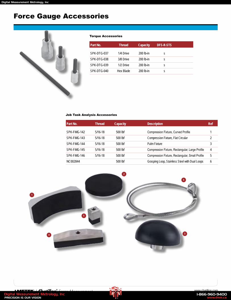
50 www.chatillon.com
Torque Accessories
Part No. Thread Capacity DFS-R-STS
SPK-DTG-037 1/4 Drive 200 lb-in s
SPK-DTG-038 3/8 Drive 200 lb-in s
SPK-DTG-039 1/2 Drive 200 lb-in s
SPK-DTG-040 Hex Blade 200 lb-in s
Force Gauge Accessories
Job Task Analysis Accessories
Part No. Thread Capacity Description Ref
SPK-FMG-142 5/16-18 500 lbf Compression Fixture, Curved Profile 1
SPK-FMG-143 5/16-18 500 lbf Compression Fixture, Flat Circular 2
SPK-FMG-144 5/16-18 500 lbf Palm Fixture 3
SPK-FMG-145 5/16-18 500 lbf Compression Fixture, Rectangular, Large Profile 4
SPK-FMG-146 5/16-18 500 lbf Compression Fixture, Rectangular, Small Profile 5
NC002844 500 lbf Grasping Loop, Stainless Steel with Dual Loops 6
1
2
34
5
6
www.dmm.ca1-866-960-9400
PRECISION IS OUR VISIONDigital Measurement Metrology, Inc
TM
Digital Measurement Metrology, Inc
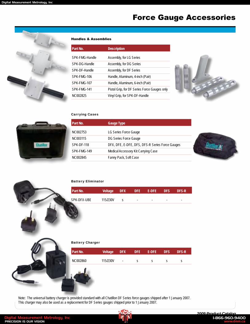
51 2009 Product Catalog
Handles & Assemblies
Part No. Description
SPK-FMG-Handle Assembly, for LG Series
SPK-DG-Handle Assembly, for DG Series
SPK-DF-Handle Assembly, for DF Series
SPK-FMG-106 Handle, Aluminum, 4-inch (Pair)
SPK-FMG-107 Handle, Aluminum, 6-inch (Pair)
SPK-FMG-141 Pistol Grip, for DF Series Force Gauges only
NC002825 Vinyl Grip, for SPK-DF-Handle
Carrying Cases
Part No. Gauge Type
NC002753 LG Series Force Gauge
NC003115 DG Series Force Gauge
SPK-DF-118 DFX, DFE, E-DFE, DFS, DFS-R Series Force Gauges
SPK-FMG-149 Medical Accessory Kit Carrying Case
NC002845 Fanny Pack, Soft Case
Battery Charger
Part No. Voltage DFX DFE E-DFE DFS DFS-R
NC002860 115/230V - s s s s
Force Gauge Accessories
Note: The universal battery charger is provided standard with all Chatillon DF Series force gauges shipped after 1 January 2007. This charger may also be used as a replacement for DF Series gauges shipped prior to 1 January 2007.
Battery Eliminator
Part No. Voltage DFX DFE E-DFE DFS DFS-R
SPK-DFX-UBE 115/230V s - - - -
www.dmm.ca1-866-960-9400
PRECISION IS OUR VISIONDigital Measurement Metrology, Inc
TM
Digital Measurement Metrology, Inc
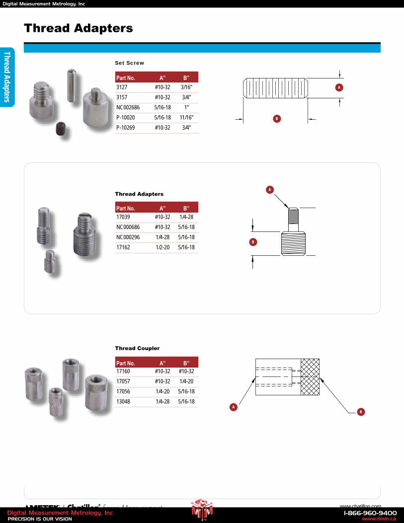
52 www.chatillon.com
Thread Adapters
Thread Adapters
Set Screw
Part No. A” B”
Thread Adapters
Part No. A” B”
Thread Coupler
Part No. A” B”
3127 #10-32 3/16”
3157 #10-32 3/4”
NC002686 5/16-18 1”
P-10020 5/16-18 11/16”
P-10269 #10-32 3/4”
17039 #10-32 1/4-28
NC000686 #10-32 5/16-18
NC000296 1/4-28 5/16-18
17162 1/2-20 5/16-18
17160 #10-32 #10-32
17057 #10-32 1/4-20
17056 1/4-20 5/16-18
13048 1/4-28 5/16-18
A
B
A
B
AB
www.dmm.ca1-866-960-9400
PRECISION IS OUR VISIONDigital Measurement Metrology, Inc
TM
Digital Measurement Metrology, Inc
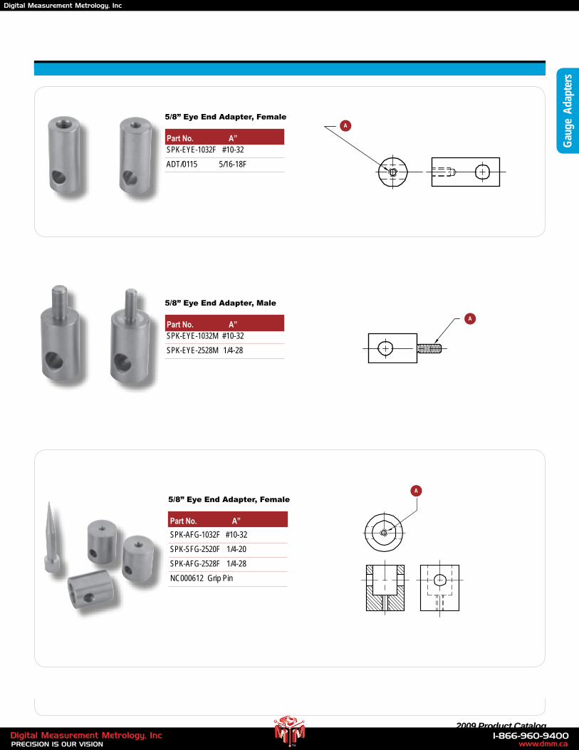
53 2009 Product Catalog
Gau
ge A
dapt
ers
5/8” Eye End Adapter, Female
Part No. A”
5/8” Eye End Adapter, Female
Part No. A”
5/8” Eye End Adapter, Male
Part No. A”
SPK-AFG-1032F #10-32
SPK-SFG-2520F 1/4-20
SPK-AFG-2528F 1/4-28
NC000612 Grip Pin
SPK-EYE-1032M #10-32
SPK-EYE-2528M 1/4-28
SPK-EYE-1032F #10-32
ADT/0115 5/16-18F
A
A
A
www.dmm.ca1-866-960-9400
PRECISION IS OUR VISIONDigital Measurement Metrology, Inc
TM
Digital Measurement Metrology, Inc
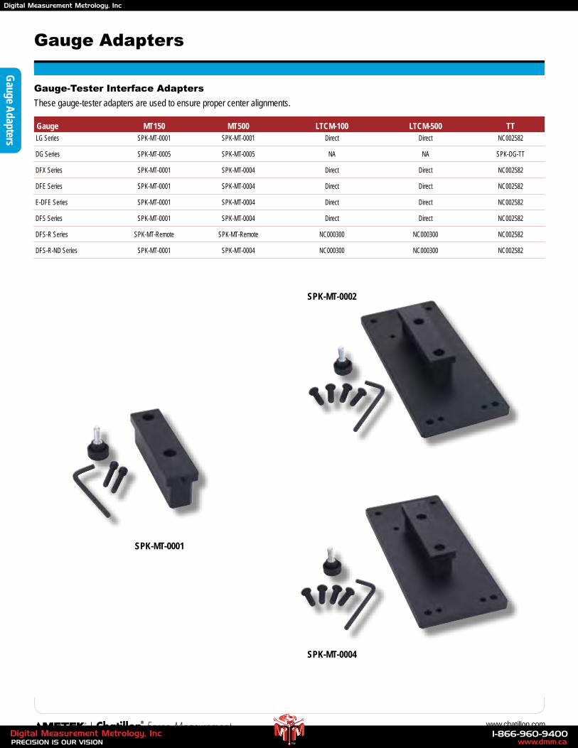
54 www.chatillon.com
Gauge A
dapters
Gauge Adapters
Gauge-Tester Interface Adapters
These gauge-tester adapters are used to ensure proper center alignments.
Gauge MT150 MT500 LTCM-100 LTCM-500 TT LG Series SPK-MT-0001 SPK-MT-0001 Direct Direct NC002582
DG Series SPK-MT-0005 SPK-MT-0005 NA NA SPK-DG-TT
DFX Series SPK-MT-0001 SPK-MT-0004 Direct Direct NC002582
DFE Series SPK-MT-0001 SPK-MT-0004 Direct Direct NC002582
E-DFE Series SPK-MT-0001 SPK-MT-0004 Direct Direct NC002582
DFS Series SPK-MT-0001 SPK-MT-0004 Direct Direct NC002582
DFS-R Series SPK-MT-Remote SPK-MT-Remote NC000300 NC000300 NC002582
DFS-R-ND Series SPK-MT-0001 SPK-MT-0004 NC000300 NC000300 NC002582
SPK-MT-0001
SPK-MT-0002
SPK-MT-0004
www.dmm.ca1-866-960-9400
PRECISION IS OUR VISIONDigital Measurement Metrology, Inc
TM
Digital Measurement Metrology, Inc
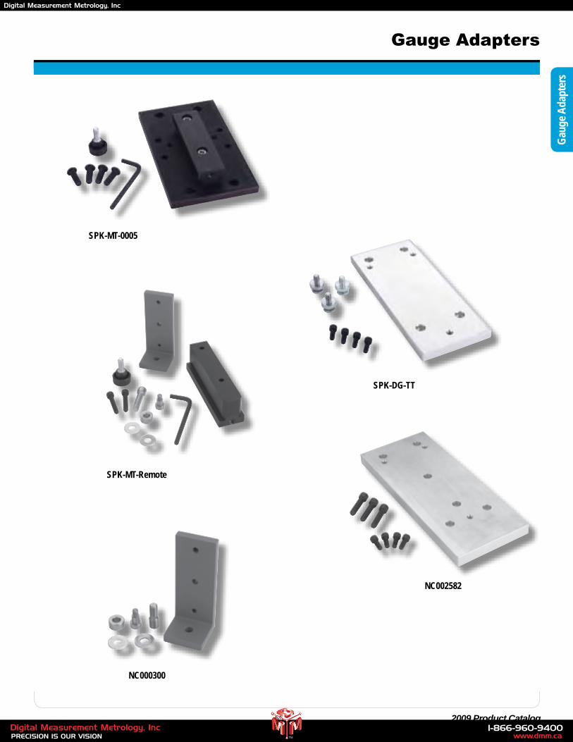
55 2009 Product Catalog
Gau
ge A
dapt
ers
Gauge Adapters
SPK-MT-0005
SPK-MT-Remote
SPK-DG-TT
NC000300
NC002582
www.dmm.ca1-866-960-9400
PRECISION IS OUR VISIONDigital Measurement Metrology, Inc
TM
Digital Measurement Metrology, Inc
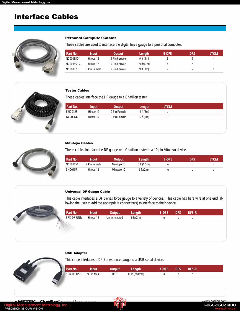
56 www.chatillon.com
Interface Cables
Personal Computer Cables
These cables are used to interface the digital force gauge to a personal computer.
Part No. Input Output Length E-DFE DFS LTCM NC000850-1 Hirose 12 9 Pin Female 9 ft (3m) S S -
NC000850-2 Hirose 12 9 Pin Female 20 ft (7m) o o -
NC000875 9 Pin Female 9 Pin Female 9 ft (3m) - - o
USB Adapter
This cable interfaces a DF Series force gauge to a USB serial device.
Universal DF Gauge Cable
This cable interfaces a DF Series force gauge to a variety of devices. This cable has bare wire at one end, al-lowing the user to add the appropriate connector(s) to interface to their device.
Tester Cables
These cables interface the DF gauge to a Chatillon tester.
Mitutoyo Cables
These cables interface the DF gauge or a Chatillon tester to a 10 pin Mitutoyo device.
Part No. Input Output Length E-DFE DFS DFS-R SPK-DF-USB 9 Pin Male USB 11 in (280mm) o o o
Part No. Input Output Length LTCM ENC0125 Hirose 12 9 Pin Female 9 ft (3m) o
NC000647 Hirose 12 9 Pin Female 6 ft (2m) -
Part No. Input Output Length E-DFE DFS LTCM NC000654 9 Pin Female Mitutoyo 10 5 ft (1.5m) o o o
ENC0157 Hirose 12 Mitutoyo 10 6 ft (2m) o o o
Part No. Input Output Length E-DFE DFS DFS-R SPK-DF-UNIV Hirose 12 Un-terminated 6 ft (2m) o o o
www.dmm.ca1-866-960-9400
PRECISION IS OUR VISIONDigital Measurement Metrology, Inc
TM
Digital Measurement Metrology, Inc
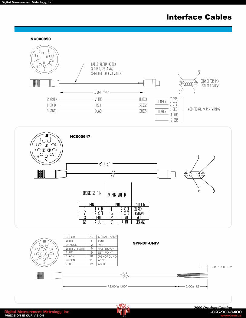
57 2009 Product Catalog
Interface Cables
NC000850
NC000647
SPK-DF-UNIV
www.dmm.ca1-866-960-9400
PRECISION IS OUR VISIONDigital Measurement Metrology, Inc
TM
Digital Measurement Metrology, Inc
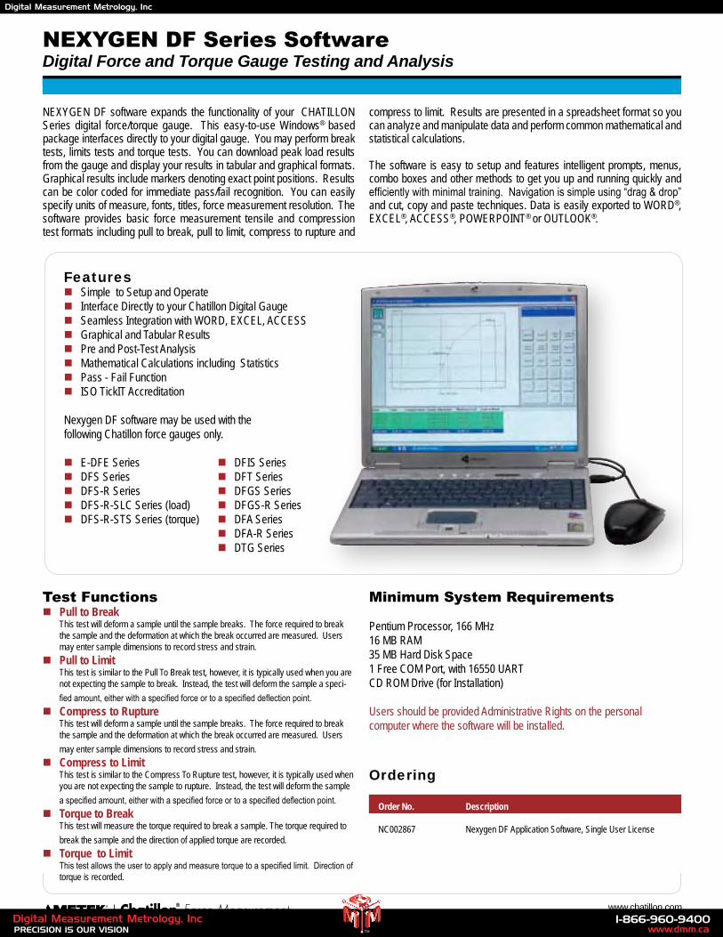
58 www.chatillon.com
NEXYGEN DF Series SoftwareDigital Force and Torque Gauge Testing and Analysis
NEXYGEN DF software expands the functionality of your CHATILLON Series digital force/torque gauge. This easy-to-use Windows® based package interfaces directly to your digital gauge. You may perform break tests, limits tests and torque tests. You can download peak load results from the gauge and display your results in tabular and graphical formats. Graphical results include markers denoting exact point positions. Results can be color coded for immediate pass/fail recognition. You can easily specify units of measure, fonts, titles, force measurement resolution. The software provides basic force measurement tensile and compression test formats including pull to break, pull to limit, compress to rupture and
compress to limit. Results are presented in a spreadsheet format so you can analyze and manipulate data and perform common mathematical and statistical calculations.
The software is easy to setup and features intelligent prompts, menus, combo boxes and other methods to get you up and running quickly and efficiently with minimal training. Navigation is simple using “drag & drop” and cut, copy and paste techniques. Data is easily exported to WORD®, EXCEL®, ACCESS®, POWERPOINT® or OUTLOOK®.
Featuresn Simple to Setup and Operaten Interface Directly to your Chatillon Digital Gaugen Seamless Integration with WORD, EXCEL, ACCESSn Graphical and Tabular Resultsn Pre and Post-Test Analysisn Mathematical Calculations including Statisticsn Pass - Fail Functionn ISO TickIT Accreditation
Nexygen DF software may be used with the following Chatillon force gauges only.
n E-DFE Series n DFIS Seriesn DFS Series n DFT Seriesn DFS-R Series n DFGS Seriesn DFS-R-SLC Series (load) n DFGS-R Seriesn DFS-R-STS Series (torque) n DFA Series n DFA-R Series n DTG Series
Minimum System Requirements
Pentium Processor, 166 MHz16 MB RAM35 MB Hard Disk Space1 Free COM Port, with 16550 UARTCD ROM Drive (for Installation)
Users should be provided Administrative Rights on the personal computer where the software will be installed.
Ordering
Order No. Description
NC002867 Nexygen DF Application Software, Single User License
Test Functionsn Pull to Break
This test will deform a sample until the sample breaks. The force required to break the sample and the deformation at which the break occurred are measured. Users may enter sample dimensions to record stress and strain.
n Pull to Limit This test is similar to the Pull To Break test, however, it is typically used when you are not expecting the sample to break. Instead, the test will deform the sample a speci-
fied amount, either with a specified force or to a specified deflection point.
n Compress to Rupture This test will deform a sample until the sample breaks. The force required to break the sample and the deformation at which the break occurred are measured. Users
may enter sample dimensions to record stress and strain.
n Compress to Limit This test is similar to the Compress To Rupture test, however, it is typically used when you are not expecting the sample to rupture. Instead, the test will deform the sample
a specified amount, either with a specified force or to a specified deflection point.
n Torque to Break This test will measure the torque required to break a sample. The torque required to
break the sample and the direction of applied torque are recorded.
n Torque to Limit This test allows the user to apply and measure torque to a specified limit. Direction of torque is recorded.
www.dmm.ca1-866-960-9400
PRECISION IS OUR VISIONDigital Measurement Metrology, Inc
TM
Digital Measurement Metrology, Inc
59 2009 Product Catalog
NOTES:
www.dmm.ca1-866-960-9400
PRECISION IS OUR VISIONDigital Measurement Metrology, Inc
TM
Digital Measurement Metrology, Inc
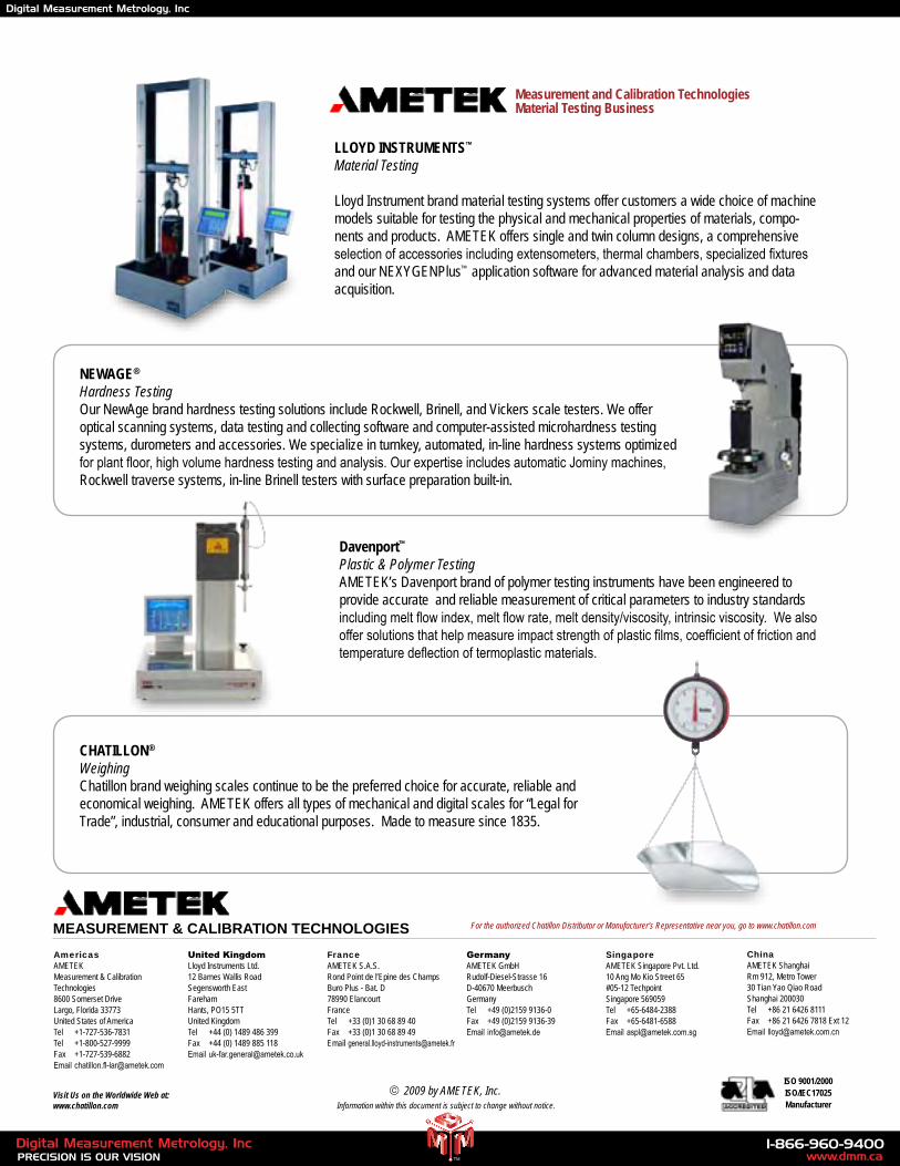
LLOYD INSTRUMENTS™
Material Testing
Lloyd Instrument brand material testing systems offer customers a wide choice of machine models suitable for testing the physical and mechanical properties of materials, compo-nents and products. AMETEK offers single and twin column designs, a comprehensive selection of accessories including extensometers, thermal chambers, specialized fixtures and our NEXYGENPlus™ application software for advanced material analysis and data acquisition.
NEWAGE®
Hardness TestingOur NewAge brand hardness testing solutions include Rockwell, Brinell, and Vickers scale testers. We offer optical scanning systems, data testing and collecting software and computer-assisted microhardness testing systems, durometers and accessories. We specialize in turnkey, automated, in-line hardness systems optimized for plant floor, high volume hardness testing and analysis. Our expertise includes automatic Jominy machines, Rockwell traverse systems, in-line Brinell testers with surface preparation built-in.
Davenport™
Plastic & Polymer TestingAMETEK’s Davenport brand of polymer testing instruments have been engineered to provide accurate and reliable measurement of critical parameters to industry standards including melt flow index, melt flow rate, melt density/viscosity, intrinsic viscosity. We also offer solutions that help measure impact strength of plastic films, coefficient of friction and temperature deflection of termoplastic materials.
CHATILLON®
Weighing Chatillon brand weighing scales continue to be the preferred choice for accurate, reliable and economical weighing. AMETEK offers all types of mechanical and digital scales for “Legal for Trade”, industrial, consumer and educational purposes. Made to measure since 1835.
ISO 9001/2000ISO/IEC17025Manufacturer
AmericasAMETEK Measurement & Calibration Technologies8600 Somerset DriveLargo, Florida 33773United States of AmericaTel +1-727-536-7831Tel +1-800-527-9999Fax +1-727-539-6882Email [email protected]
Measurement and Calibration TechnologiesMaterial Testing Business
MeaSureMenT & CaLiBraTion TeChnoLogieSFranceAMETEK S.A.S.Rond Point de l’Epine des ChampsBuro Plus - Bat. D78990 ElancourtFranceTel +33 (0)1 30 68 89 40Fax +33 (0)1 30 68 89 49Email [email protected]
GermanyAMETEK GmbHRudolf-Diesel-Strasse 16D-40670 MeerbuschGermanyTel +49 (0)2159 9136-0Fax +49 (0)2159 9136-39Email [email protected]
SingaporeAMETEK Singapore Pvt. Ltd.10 Ang Mo Kio Street 65#05-12 TechpointSingapore 569059Tel +65-6484-2388Fax +65-6481-6588Email [email protected]
For the authorized Chatillon Distributor or Manufacturer’s Representative near you, go to www.chatillon.com
Visit Us on the Worldwide Web at:www.chatillon.com Information within this document is subject to change without notice.
2009 by AMETEK, Inc.
United KingdomLloyd Instruments Ltd.12 Barnes Wallis RoadSegensworth EastFarehamHants, PO15 5TTUnited KingdomTel +44 (0) 1489 486 399Fax +44 (0) 1489 885 118 Email [email protected]
ChinaAMETEK ShanghaiRm 912, Metro Tower30 Tian Yao Qiao RoadShanghai 200030Tel +86 21 6426 8111Fax +86 21 6426 7818 Ext 12Email [email protected]
www.dmm.ca1-866-960-9400
PRECISION IS OUR VISIONDigital Measurement Metrology, Inc
TM
Digital Measurement Metrology, Inc