Embed Size (px)
Citation preview
Association of Radio Industries and Businesses
OFDMA / TDMA TDD Broadband Wireless Access System
(Next Generation PHS)
ARIB STD-T95
ARIB STANDARD
Version 1.0 December 12th 2007Version 1.1 June 6th 2008Version 1.2 March 18th 2009Version 1.3 December 16th 2009Version 2.0 July 7th 2011
ARIB STD-T95 Version 2.0
General Notes to ARIB Standards and Technical Reports.
1. The copyright of this document is ascribed to the Association of Radio Industries and Businesses
(ARIB).
2. All rights reserved. No part of this document may be reproduced, stored in a retrieval system, or
transmitted, in any form or by any means, without the prior written permission of ARIB.
3. Attachment 3 is reproduced with the consent of XGP Forum which owns the copyright in it.
4. The establishment, revision and abolishment of ARIB Standards are approved at the ARIB Standard
Assembly which meets several times a year. Approved ARIB Standards in their original language
are made publicly available in hard copy, CDs or through web posting, generally in about one month
after the date of approval.
5. The note about IPR (Industrial Property Rights) of the standard applies to the use of Essential IPR
for the ARIB Standard in Japan. If the ARIB Standard is adopted outside Japan, Essential IPR will
be treated in accordance with policies stated by each IPR owner. The IPR owners are, however,
expected to apply the rules of the preface of the "Guidelines for Treatment of Industrial Property
Rights in connection with the ARIB standard” (September 5, 1995, approved by the 1st Standard
Assembly Meeting). In the preface of the Guidelines, it is stated that it is "desirable that the
Essential IPR which relates to any or all parts of the contents of the ARIB Standards should be used
free of charge by anyone and that it would not block the uses of such Essential IPR in any other
country where such an ARIB Standard is adopted"
ARIB STD-T95
Preface
Introduction
Association of Radio Industries and Businesses (hereinafter ARIB) investigates and
summarizes the basic technical requirements for various radio systems in the form of “technical
standard (ARIB STD)”. These standards are being developed with the participation of, and
through discussions amongst various radio equipment manufacturers, operators and users.
ARIB standards include “government technical standards” (mandatory standards) that are
set for the purpose of encouraging effective use of frequency resources and preventing
interference, and “private technical standards” (voluntary standards) that are defined in order
to guarantee compatibility between radio facilities, to secure adequate transmission quality as
well as to offer greater convenience to radio equipment manufacturers and users, etc.
An ARIB STANDARD herein is published as "OFDMA / TDMA TDD Broadband Wireless
Access System (Next Generation PHS)". In order to ensure fairness and transparency in the
defining stage, the standard was set by consensus of the standard council with participation of
interested parties including radio equipment manufacturers, telecommunications operators,
broadcasters, testing organizations, general users, etc. with impartiality.
ARIB sincerely hopes that this standard be utilized actively by radio equipment
manufacturers, telecommunications operators, and users, etc.

ARIB STD-T95
INDUSTRIAL PROPERTY RIGHTS (IPRs)
Although this ARIB Standard contains no specific reference to any Essential Industrial
Property Rights relating thereto, the holders of such Essential Industrial Property Rights state
to the effect that the rights listed in Attachment 1 and 2, which are the Industrial Property
Rights relating to this standard, are held by the parties also listed therein, and that to the users
of this standard, in the case of Attachment 1 (selection of option 1), such holders shall not assert
any rights and shall unconditionally grant a license to practice such Industrial Property Rights
contained therein, and in the case of Attachment 2 (selection of option 2), the holders shall grant,
under the reasonable terms and conditions, a non-exclusive and non-discriminatory license to
practice the Industrial Property Rights contained therein. However, this does not apply to
anyone who uses this ARIB Standard and also owns and lays claim to any other Essential
Industrial Property Rights of which is covered in whole or part in the contents of provisions of
this ARIB Standard.
List of Essential Industrial Property Rights (IPRs)
The lists of Essential Industrial Property Rights (IPRs) are shown in the following
attachments.
Attachment 1 List of Essential Industrial Property Rights (selection of option 1)
Attachment 2 List of Essential Industrial Property Rights (selection of option 2)

ARIB STD-T95
-i-
Contents
Preface
INTRODUCTION
INDUSTRIAL PROPERTY RIGHTS (IPRs)
List of Essential Industrial Property Rights (IPRs)
Chapter 1 General Descriptions.......................................................................................................1
1.1 Overview...............................................................................................................................1
1.2 Scope of the Standard ..........................................................................................................1
1.3 Reference Regulations .........................................................................................................2
1.4 Reference Documents...........................................................................................................2
Chapter 2 Technical Requirements for Radio Facilities..................................................................3
2.1 General Conditions ..............................................................................................................3
2.1.1 System Structure (ORE,Article 49.29) .........................................................................3
2.1.2 Radio Frequency Band (ORE,Article 49.29).................................................................3
2.1.3 Modulation Method (ORE,Article 49.29)......................................................................3
2.1.4 General Requirement (ORE,Article 49.29)...................................................................3
2.2 Conditions Relating to Transmitter and Receiver..............................................................4
2.2.1 Transmission Characteristics .......................................................................................4
2.2.1.1 Transmission Power (ORE,Article 49.29) (ORE.Article 14) (NT No.651, 2007)...4
2.2.1.2 Adjacent Channel Power (NT No.651, 2007) .........................................................6
2.2.1.3 Transmission Intermodulation (NT No.651, 2007) ...............................................8
2.2.1.4 Transmission Synchronization (NT No. 651, 2007)...............................................9
2.2.1.5 Carrier off Time Leakage Power (ORE,Article 49.29).........................................11
2.2.1.6 Tolerance Limits of the Intensity of Unwanted Emission in Spurious Domain
(NT No.651, 2007).................................................................................................11
2.2.1.7 Allowed Value for Occupied Bandwidth (ORE, Article 6,Table 2).......................14
2.2.1.8 Frequency Stability (ORE, Article 5,Table 1) ......................................................14
2.2.1.9 Transmission Antennas (ORE,Article 49.29).......................................................15
2.2.1.10 SAR (ORE,Article 14.2) ......................................................................................15
2.2.2 Reception Characteristics ...........................................................................................15
2.2.2.1 Sensitivity .............................................................................................................15
2.2.2.2 Adjacent Channel Selectivity ...............................................................................15
2.2.2.3 Intermodulation Characteristic ...........................................................................16

ARIB STD-T95
-ii-
2.2.2.4 Spurious Response Immunity ..............................................................................16
2.2.2.5 Conducted Spurious Component (ORE,Article 24) .............................................17
Chapter 3 Physical and MAC Layer Specifications.......................................................................20
Chapter 4 Japanese specific matters .............................................................................................21
Chapter 5 Measurement Method ...................................................................................................22
Attachment
Attachment 1 List of Essential Industrial Property Rights (selection of option 1)
Attachment 2 List of Essential Industrial Property Rights (selection of option 2)
Attachment 3 Next Generation PHS specifications
Change History
ARIB STD-T95
-1-
Chapter 1 General Descriptions
1.1 Overview
This standard specifies requirements of the radio equipment of radio stations stipulated in
the Ministry of Internal Affair and Communications (MIC), Ordinance Regulating Radio
Equipment, Article 49.29 (this refers to the radio equipment of radio stations of OFDMA / TDMA
or SC-FDMA/TDMA TDD Broadband Wireless Access System using 2.5 GHz band. Next
Generation PHS, which is defined as the technology for personal wireless broadband services
based on all-IP core network.
The standard shall be in accordance with MIC Ordinance Regulating Radio Equipment,
Article 49.29 (including related notifications) when Next Generation PHS facilities are used in
Japan.
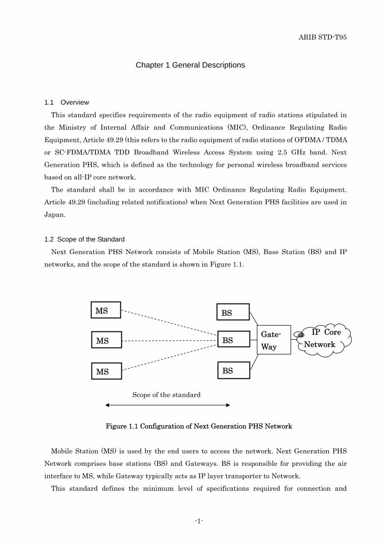
1.2 Scope of the Standard
Next Generation PHS Network consists of Mobile Station (MS), Base Station (BS) and IP
networks, and the scope of the standard is shown in Figure 1.1.
Figure 1.1 Configuration of Next Generation PHS Network
Mobile Station (MS) is used by the end users to access the network. Next Generation PHS
Network comprises base stations (BS) and Gateways. BS is responsible for providing the air
interface to MS, while Gateway typically acts as IP layer transporter to Network.
This standard defines the minimum level of specifications required for connection and
MS
MS
MS
IP Core
Network
Scope of the standard
BS
BS
BS
Gate-
Way

ARIB STD-T95
-2-
services for Next Generation PHS. This consists of two different specifications, i.e., Japanese
regulatory specifications applied for radio systems, and Physical and MAC layers specifications.
The Japanese regulatory specifications are developed by national regulatory administration, i.e.
the Ministry of Internal Affair and Communications (MIC). The physical and MAC layers
specifications are developed by international standard organization, i.e., XGP Forum.
This standard is intended to combine the national regulations and the international
specifications, however in case of inconsistency between them, the national regulations shall
prevail. The national regulations are the mandatory requirements for operation of Next
Generation PHS in Japan.
1.3 Reference Regulations
The acronyms of the referenced regulations used in this standard are as follows;
RERL : Regulations for Enforcement of Radio Law
ORE : Ordinance Regulating Radio Equipment
OTRCC: Ordinance Concerning Technical Regulations Conformity Certification etc. of
Specified Radio Equipment.
OTF: Ordinance Concerning Terminal Facilities etc.
RTCCA: Rules Concerning the Technical Conditions Compliance approval etc. for Terminal
Equipment.
NT: “Notification” refers to a Notification of the Ministry of Internal Affairs and
Communications.
1.4 Reference Documents
- A-GN4.00-02-TS “Next Generation PHS Specifications”
ARIB STD-T95
-3-
Chapter 2 Technical Requirements for Radio Facilities
This chapter has regulations regarding the technical requirements for radio facilities for the
radio station of Next Generation PHS in Japan.
MIC Ordinances and related Notifications contained in the chapter 2 are translated into
English from the original Japanese regulations of MIC Ordinances and related Notifications.
The original Japanese regulations shall prevail if any ambiguity exists between the
requirements and the original in Japanese.
2.1 General Conditions
2.1.1 System Structure (ORE,Article 49.29)
(1) Base Station (BS)
(2) Mobile Station (MS)
(3) Relay Station (RS)
For the technical requirement of RS, the radio equipment (uplink) which communicates
with BS complies with the technical requirement of MS and the radio equipment
(downlink) which communicates with MS complies with the technical requirement of BS.
(4) Radio station which establishes communication and other operation for maintenance of
radio equipment
If communication is not possible between a radio station which establishes
communication to maintain or adjust a radio equipment of BS in OFDM / TDM access
scheme broadband mobile radio access system or such BS and MS which is a partner of
such BS in communication, it means a radio station operating as RS.
2.1.2 Radio Frequency Band (ORE,Article 49.29)
The radio frequency band is the 2.5 GHz band (over 2,545 MHz - 2,625 MHz or less).
2.1.3 Modulation Method (ORE,Article 49.29)
The modulation methods are BPSK, QPSK, 16QAM, 32QAM, 64QAM and 256QAM.
2.1.4 General Requirement (ORE,Article 49.29)
(1) Communication method shall be as follows:
- For transmission from BS or RS to MS, or from BS to RS; (downlink)
The multiplexing method is a combination of OFDM and TDM, or OFDM, TDM and
SDM.

ARIB STD-T95
-4-
- For transmission from MS or RS to BS, or from MS to RS; (uplink)
The access method is a combination of OFDMA and TDMA, a combination of
OFDMA,TDMA and SDMA, or a combination of SC-FDMA and TDMA, a combination of
SC-FDMA,TDMA and SDMA.
(2) Transmission equipment of each MS which establishes communication with BS or RS
shall be automatically identified.
(3) Switching from a traffic channel of one BS or RS to a traffic channel of other BS shall be
automatically performed. (Except that communication system is configured by MS with
absolute gain of transmission antenna of over 4 dBi.)
(4) Radio equipment of BS shall be connectable to telecommunication circuit equipment.
(5) The power supply of radio equipment in MS with absolute gain of transmission antenna
of over 4 dBi to 10 dBi or less shall be AC (alternate current) power.
(6) The radio frequency transmitted from MS shall be automatically selected by receiving
the radio wave from its partner BS or radio station which establishes communication to
test the radio equipment in this system.
(7) In addition to the above items, radio equipment shall comply with the technical
requirement separately notified by Minister for Internal Affairs and Communications.
2.2 Conditions Relating to Transmitter and Receiver
2.2.1 Transmission Characteristics
2.2.1.1 Transmission Power (ORE,Article 49.29) (ORE.Article 14) (NT No.651, 2007)
(1) The transmission power of BS shall be as follows.
Table 2.1 Transmission Power of BS
The absolute gain of transmission antenna The transmission power
17 dBi or less (Note1) 2.5/5/10MHz System: 20 W or less
20MHz system: 40 W or less
Over 17 dBi to 20 dBi or less (Note1, 2) 20 W or less
Over 20 dBi to 23 dBi or less (Note1, 2) 5 W or less
Over 23 dBi to 25 dBi or less (Note1, 2) 3.2 W or less
Note1: The following transmitter shall be limited for use in depopulated areas, mountain
villages, isolated island areas or the areas authorized by Minister of Internal Affairs
and Communications
; The transmitter in BS that communicates with MS or RS of which absolute gain of
ARIB STD-T95
-5-
transmission antenna exceeds 4 dBi.
; The transmitter in BS with absolute gain of transmission antenna of over 17 dBi.
Note2: The BS with absolute gain of transmitting antenna of over 17 dBi shall communicate
with only one radio station.
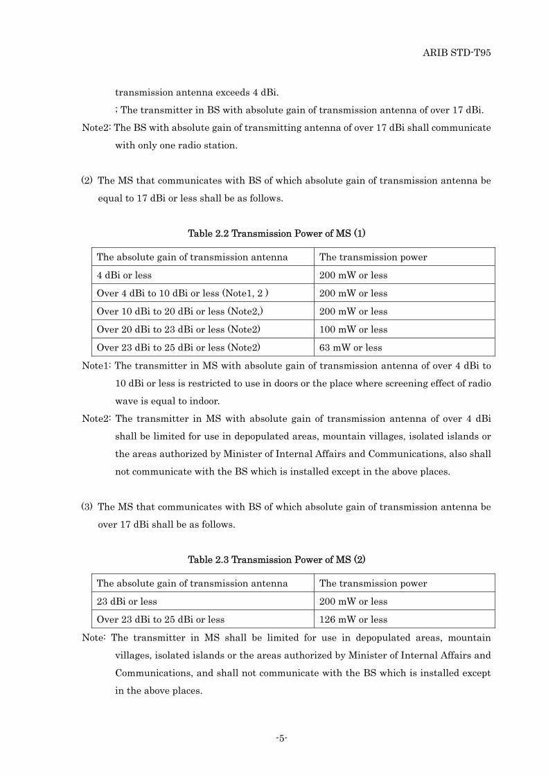
(2) The MS that communicates with BS of which absolute gain of transmission antenna be
equal to 17 dBi or less shall be as follows.
Table 2.2 Transmission Power of MS (1)
The absolute gain of transmission antenna The transmission power
4 dBi or less 200 mW or less
Over 4 dBi to 10 dBi or less (Note1, 2 ) 200 mW or less
Over 10 dBi to 20 dBi or less (Note2,) 200 mW or less
Over 20 dBi to 23 dBi or less (Note2) 100 mW or less
Over 23 dBi to 25 dBi or less (Note2) 63 mW or less
Note1: The transmitter in MS with absolute gain of transmission antenna of over 4 dBi to
10 dBi or less is restricted to use in doors or the place where screening effect of radio
wave is equal to indoor.
Note2: The transmitter in MS with absolute gain of transmission antenna of over 4 dBi
shall be limited for use in depopulated areas, mountain villages, isolated islands or
the areas authorized by Minister of Internal Affairs and Communications, also shall
not communicate with the BS which is installed except in the above places.
(3) The MS that communicates with BS of which absolute gain of transmission antenna be
over 17 dBi shall be as follows.
Table 2.3 Transmission Power of MS (2)
The absolute gain of transmission antenna The transmission power
23 dBi or less 200 mW or less
Over 23 dBi to 25 dBi or less 126 mW or less
Note: The transmitter in MS shall be limited for use in depopulated areas, mountain
villages, isolated islands or the areas authorized by Minister of Internal Affairs and
Communications, and shall not communicate with the BS which is installed except
in the above places.
ARIB STD-T95
-6-
(4) The transmitter in RS
- Transmission to BS:
The value for MS shown in the Table 2.2 and Table 2.3 should be referred.
- Transmission to MS:
The value for BS shown in the Table 2.1 should be referred.
Tolerance for transmission power:
a) BS: Within +87 %, -47 %
b) MS: Within +87 %, -47 %
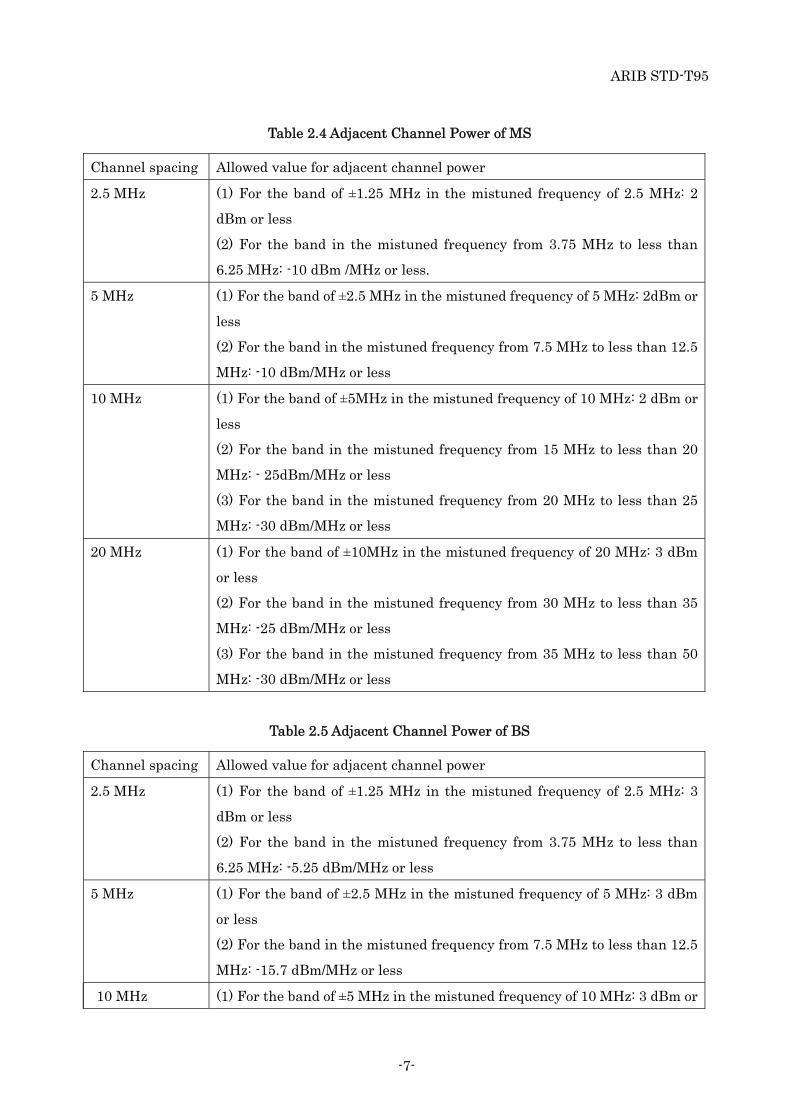
2.2.1.2 Adjacent Channel Power (NT No.651, 2007)
(1) Standards
The adjacent channel power of the transmitter in RS shall apply as follows.
- Transmission to BS:
The value for MS shown in the Table 2.4 should be referred.
- Transmission to MS:
The value for BS shown in the Table 2.5 should be referred.
ARIB STD-T95
-7-
Table 2.4 Adjacent Channel Power of MS
Channel spacing Allowed value for adjacent channel power
2.5 MHz (1) For the band of ±1.25 MHz in the mistuned frequency of 2.5 MHz: 2
dBm or less
(2) For the band in the mistuned frequency from 3.75 MHz to less than
6.25 MHz: -10 dBm /MHz or less.
5 MHz (1) For the band of ±2.5 MHz in the mistuned frequency of 5 MHz: 2dBm or
less
(2) For the band in the mistuned frequency from 7.5 MHz to less than 12.5
MHz: -10 dBm/MHz or less
10 MHz (1) For the band of ±5MHz in the mistuned frequency of 10 MHz: 2 dBm or
less
(2) For the band in the mistuned frequency from 15 MHz to less than 20
MHz: - 25dBm/MHz or less
(3) For the band in the mistuned frequency from 20 MHz to less than 25
MHz: -30 dBm/MHz or less
20 MHz (1) For the band of ±10MHz in the mistuned frequency of 20 MHz: 3 dBm
or less
(2) For the band in the mistuned frequency from 30 MHz to less than 35
MHz: -25 dBm/MHz or less
(3) For the band in the mistuned frequency from 35 MHz to less than 50
MHz: -30 dBm/MHz or less
Table 2.5 Adjacent Channel Power of BS
Channel spacing Allowed value for adjacent channel power
2.5 MHz (1) For the band of ±1.25 MHz in the mistuned frequency of 2.5 MHz: 3
dBm or less
(2) For the band in the mistuned frequency from 3.75 MHz to less than
6.25 MHz: -5.25 dBm/MHz or less
5 MHz (1) For the band of ±2.5 MHz in the mistuned frequency of 5 MHz: 3 dBm
or less
(2) For the band in the mistuned frequency from 7.5 MHz to less than 12.5
MHz: -15.7 dBm/MHz or less
10 MHz (1) For the band of ±5 MHz in the mistuned frequency of 10 MHz: 3 dBm or

ARIB STD-T95
-8-
less
(2) For the band in the mistuned frequency from 15 MHz to less than 25
MHz: -22 dBm/MHz or less
20 MHz (1) For the band of ±10MHz in the mistuned frequency of 20 MHz: 6 dBm
or less
(2) For the band in the mistuned frequency from 30 MHz to less than 50
MHz: - 22 dBm/MHz or less
2.2.1.3 Transmission Intermodulation (NT No.651, 2007)
Intermodulation characteristic of BS and RS (only RS transmitted to MS) shall be as follows.
(1) Channel spacing of 2.5 MHz
Under the condition of rated output desired wave, when the interference wave of +/-2.5
MHz and +/-5 MHz away from the desired wave is added by the transmission power of 30
dB lower than the rated output desired wave, intermodulation power shall not exceed the
allowed value of adjacent channel power (2.2.1.2 adjacent channel power).
(2) Channel spacing of 5 MHz
Under the condition of rated output desired wave, when the interference wave of +/-5
MHz and +/-10 MHz away from the desired wave is added by the transmission power of
30 dB lower than the rated output desired wave, intermodulation power shall not exceed
the allowed value of adjacent channel power (2.2.1.2 adjacent channel power).
(3) Channel spacing of 10 MHz
Under the condition of rated output desired wave, when the interference wave of +/-10
MHz and +/-20 MHz away from the desired wave is added by the transmission power of
30 dB lower than the rated output desired wave, intermodulation power shall not exceed
the allowed value of adjacent channel power (2.2.1.2 adjacent channel power).
(4) Channel spacing of 20 MHz
Under the condition of rated output desired wave, when the interference wave of +/-20
MHz and +/-40 MHz away from the desired wave is added by the transmission power of
30 dB lower than the rated output desired wave, intermodulation power shall not exceed
the allowed value of adjacent channel power (2.2.1.2 adjacent channel power).

ARIB STD-T95
-9-
2.2.1.4 Transmission Synchronization (NT No. 651, 2007)
(1) Transmission burst cycle
Within 2.5 msec,5 msec, 10 msec
(2) Transmission burst length
a) For using the frequency of over 2545 MHz to 2575 MHz or less, or over 2595 MHz
to 2625 MHz or less.
Table 2.6 Transmission Burst Length in Case a)
BS MS
Within M×625μs Within N×625μs
*M+N=4,8,or16 (M,N is a positive integer)
b) For using the frequency of over 2575 MHz to 2595 MHz (Note 1,2,3,4)
Table 2.7 Transmission Burst Length in Case b)
BS MS
3.65 msec 1.35 msec
3.55 msec 1.45 msec
3.45 msec 1.55 msec
3.35 msec 1.65 msec
3.25 msec 1.75 msec
3.15 msec 1.85 msec
3.05 msec 1.95 msec
2.95 msec 2.05 msec
2.85 msec 2.15 msec
2.75 msec 2.25 msec
Note1: Allowed value for transmission burst length of BS is from -90 μsec or more to 10 μsec
or less. Allowed value for transmission burst length of MS is from -130 μsec or more
to 10 μsec or less.
Note2: Transmission burst length for the radio frequency of over 2575 MHz to 2595 MHz or
less shall be equal to the transmission burst length for the radio equipment in BS
and MS in the certified service plan for a specific BS used by one party of the
certified parties according to the requirement of Radio Law 27.13.1 for the use of the
frequency of over 2545 MHz to 2575 MHz or less or over 2595 MHz to 2625 MHz.
Note3: The transmitter in RS

ARIB STD-T95
-10-
- Transmission to BS should be referring the value for MS.
- Transmission to MS should be referring the value for BS.
Note4: Such burst length is not defined in the standard of Next Generation PHS referred to
Chapter 3 at this time.
ARIB STD-T95
-11-
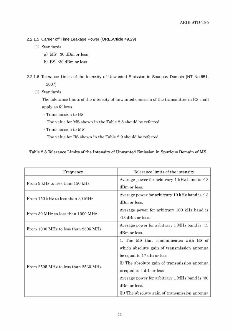
2.2.1.5 Carrier off Time Leakage Power (ORE,Article 49.29)
(1) Standards
a) MS: -30 dBm or less
b) BS: -30 dBm or less
2.2.1.6 Tolerance Limits of the Intensity of Unwanted Emission in Spurious Domain (NT No.651,
2007)
(1) Standards
The tolerance limits of the intensity of unwanted emission of the transmitter in RS shall
apply as follows.
- Transmission to BS:
The value for MS shown in the Table 2.8 should be referred.
- Transmission to MS:
The value for BS shown in the Table 2.9 should be referred.
Table 2.8 Tolerance Limits of the Intensity of Unwanted Emission in Spurious Domain of MS
Frequency Tolerance limits of the intensity
From 9 kHz to less than 150 kHz Average power for arbitrary 1 kHz band is -13
dBm or less.
From 150 kHz to less than 30 MHz Average power for arbitrary 10 kHz band is -13
dBm or less.
From 30 MHz to less than 1000 MHz Average power for arbitrary 100 kHz band is
-13 dBm or less.
From 1000 MHz to less than 2505 MHz Average power for arbitrary 1 MHz band is -13
dBm or less.
From 2505 MHz to less than 2530 MHz
1. The MS that communicates with BS of
which absolute gain of transmission antenna
be equal to 17 dBi or less
(i) The absolute gain of transmission antenna
is equal to 4 dBi or less
Average power for arbitrary 1 MHz band is -30
dBm or less.
(ii) The absolute gain of transmission antenna

ARIB STD-T95
-12-
is over 4 dBi to 10 dBi or less
Average power for arbitrary 1 MHz band is -70
dBm or less.
(iii) The absolute gain of transmission antenna
is over 10 dBi
Average power for arbitrary 1 MHz band is -68
dBm or less.
2. The MS that communicates with BS of
which absolute gain of transmission antenna
exceed 17 dBi.
Average power for arbitrary 1 MHz band is -61
dBm or less.
From 2530 MHz to less than 2535 MHz
1. The MS that communicates with BS of
which absolute gain of transmission antenna
be equal to 17 dBi or less.
(i) The absolute gain of transmission antenna
is equal to 4 dBi or less.
Average power for arbitrary 1 MHz band is
equal to -25 dBm or less
F shall be within the frequency band described
in the left column.
(ii) The absolute gain of transmission antenna
is over 4 dBi to 10 dBi or less.
Average power for arbitrary 1 MHz band is -70
dBm or less.
(iii) The absolute gain of transmission antenna
is over 10 dBi.
Average power for arbitrary 1 MHz band is -68
dBm or less.
2. The MS that communicates with BS of
which absolute gain of transmission antenna
exceed 17 dBi.
Average power for arbitrary 1 MHz band is -61
dBm or less.

ARIB STD-T95
-13-
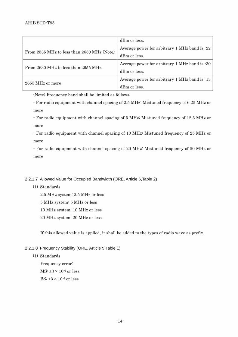
From 2535 MHz to less than 2630 MHz (Note)Average power for arbitrary 1 MHz band is -30
dBm or less.
From 2630 MHz to less than 2640 MHz
Average power for arbitrary 1 MHz band is
equal to or less than the value obtained by the
following formula:
-20 - ( F – 2630 ) dBm
F shall be within the frequency band described
in the left column.
From 2640 MHz to less than 2655 MHz Average power for arbitrary 1 MHz band is -30
dBm or less.
2655 MHz or more Average power for arbitrary 1 MHz band is -13
dBm or less.
(Note) Frequency band shall be limited as follows:
- For radio equipment with channel spacing of 2.5 MHz: Mistuned frequency of 6.25 MHz or
more
- For radio equipment with channel spacing of 5 MHz: Mistuned frequency of 12.5 MHz or
more
- For radio equipment with channel spacing of 10 MHz: Mistuned frequency of 25 MHz or
more
- For radio equipment with channel spacing of 20 MHz: Mistuned frequency of 50 MHz or
more
Table 2.9 Tolerance Limits of the Intensity of Unwanted Emission in Spurious Domain of BS
Frequency Tolerance limits of the intensity
From 9 kHz to less than 150 kHz Average power for arbitrary 1 kHz band is -13
dBm or less.
From 150 kHz to less than 30 MHz Average power for arbitrary 10 kHz band is -13
dBm or less.
From 30 MHz to less than 1000 MHz Average power for arbitrary 100 kHz band is
-13 dBm or less.
From 1000 MHz to less than 2505 MHz Average power for arbitrary 1 MHz band is -13
dBm or less.
From 2505 MHz to less than 2535 MHz Average power for arbitrary 1 MHz band is -42
ARIB STD-T95
-14-
dBm or less.
From 2535 MHz to less than 2630 MHz (Note)Average power for arbitrary 1 MHz band is -22
dBm or less.
From 2630 MHz to less than 2655 MHz Average power for arbitrary 1 MHz band is -30
dBm or less.
2655 MHz or more Average power for arbitrary 1 MHz band is -13
dBm or less.
(Note) Frequency band shall be limited as follows:
- For radio equipment with channel spacing of 2.5 MHz: Mistuned frequency of 6.25 MHz or
more
- For radio equipment with channel spacing of 5 MHz: Mistuned frequency of 12.5 MHz or
more
- For radio equipment with channel spacing of 10 MHz: Mistuned frequency of 25 MHz or
more
- For radio equipment with channel spacing of 20 MHz: Mistuned frequency of 50 MHz or
more
2.2.1.7 Allowed Value for Occupied Bandwidth (ORE, Article 6,Table 2)
(1) Standards
2.5 MHz system: 2.5 MHz or less
5 MHz system: 5 MHz or less
10 MHz system: 10 MHz or less
20 MHz system: 20 MHz or less
If this allowed value is applied, it shall be added to the types of radio wave as prefix.
2.2.1.8 Frequency Stability (ORE, Article 5,Table 1)
(1) Standards
Frequency error:
MS: ±3 × 10⁻⁶ or less
BS: ±3 × 10⁻⁶ or less
ARIB STD-T95
-15-
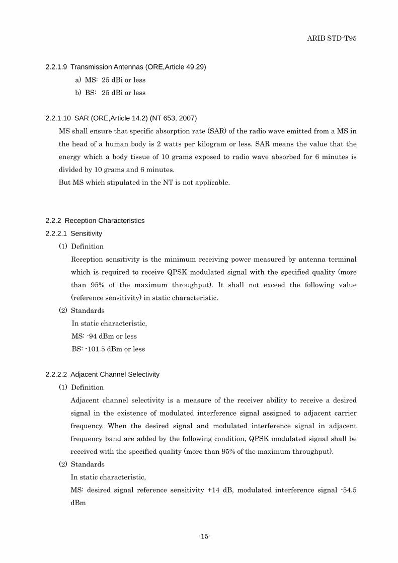
2.2.1.9 Transmission Antennas (ORE,Article 49.29)
a) MS: 25 dBi or less
b) BS: 25 dBi or less
2.2.1.10 SAR (ORE,Article 14.2) (NT 653, 2007)
MS shall ensure that specific absorption rate (SAR) of the radio wave emitted from a MS in
the head of a human body is 2 watts per kilogram or less. SAR means the value that the
energy which a body tissue of 10 grams exposed to radio wave absorbed for 6 minutes is
divided by 10 grams and 6 minutes.
But MS which stipulated in the NT is not applicable.
2.2.2 Reception Characteristics
2.2.2.1 Sensitivity
(1) Definition
Reception sensitivity is the minimum receiving power measured by antenna terminal
which is required to receive QPSK modulated signal with the specified quality (more
than 95% of the maximum throughput). It shall not exceed the following value
(reference sensitivity) in static characteristic.
(2) Standards
In static characteristic,
MS: -94 dBm or less
BS: -101.5 dBm or less
2.2.2.2 Adjacent Channel Selectivity
(1) Definition
Adjacent channel selectivity is a measure of the receiver ability to receive a desired
signal in the existence of modulated interference signal assigned to adjacent carrier
frequency. When the desired signal and modulated interference signal in adjacent
frequency band are added by the following condition, QPSK modulated signal shall be
received with the specified quality (more than 95% of the maximum throughput).
(2) Standards
In static characteristic,
MS: desired signal reference sensitivity +14 dB, modulated interference signal -54.5
dBm
ARIB STD-T95
-16-
BS: desired signal reference sensitivity +6 dB, modulated interference signal -52 dBm
2.2.2.3 Intermodulation Characteristic
(1) Definition
Intermodulation characteristic is a measure of the receiver ability to receive a desired
signal in the existence of two non-modulated interference signals which are equal in
power and can generate the third-order intermodulation or either modulated
interference signal of such two interference signals. When the desired signal and both of
non-modulated and modulated interference signals, which can generate the third-order
intermodulation, are added by the following condition, QPSK modulated signal shall be
received with the specified quality (more than 95% of the maximum throughput).
(2) Standards
In static characteristic,
MS: desired signal: reference sensitivity +9 dB
non-modulated interference signal (adjacent channel): -46dBm
modulated interference signal (second adjacent channel): -46 dBm
BS: desired signal: reference sensitivity +6 dB
non-modulated interference signal (adjacent channel): -52 dBm
modulated interference signal (second adjacent channel): -52 dBm
2.2.2.4 Spurious Response Immunity
(1) Definition
Spurious response is a measure of the receiver ability to receive a desired signal in the
existence of a non-modulated interference signal. When the desired signal and
non-modulated interference signal are added by the following condition, QPSK
modulated signal shall be received with the specified quality (more than 95% of the
maximum throughput).
(2) Standards
In static characteristic,
MS: desired signal reference sensitivity +9 dB, non-modulated interference signal: -44
dBm
BS: desired signal reference sensitivity +6 dB, non-modulated interference signal: -45
dBm
ARIB STD-T95
-17-
2.2.2.5 Conducted Spurious Component (ORE,Article 24)
(1) Definition
Conducted spurious component is spurious emissions while reception, which are any
emissions present at the antenna terminals of the equipment.
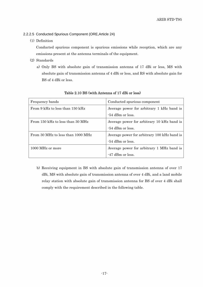
(2) Standards
a) Only BS with absolute gain of transmission antenna of 17 dBi or less, MS with
absolute gain of transmission antenna of 4 dBi or less, and RS with absolute gain for
BS of 4 dBi or less.
Table 2.10 BS (with Antenna of 17 dBi or less)
Frequency bands Conducted spurious component
From 9 kHz to less than 150 kHz Average power for arbitrary 1 kHz band is
-54 dBm or less.
From 150 kHz to less than 30 MHz Average power for arbitrary 10 kHz band is
-54 dBm or less.
From 30 MHz to less than 1000 MHz Average power for arbitrary 100 kHz band is
-54 dBm or less.
1000 MHz or more Average power for arbitrary 1 MHz band is
-47 dBm or less.
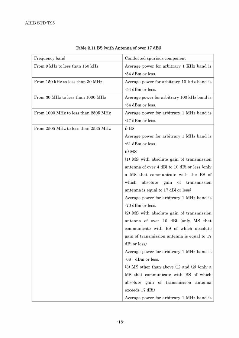
b) Receiving equipment in BS with absolute gain of transmission antenna of over 17
dBi, MS with absolute gain of transmission antenna of over 4 dBi, and a land mobile
relay station with absolute gain of transmission antenna for BS of over 4 dBi shall
comply with the requirement described in the following table.
ARIB STD-T95
-18-
Table 2.11 BS (with Antenna of over 17 dBi)
Frequency band Conducted spurious component
From 9 kHz to less than 150 kHz Average power for arbitrary 1 KHz band is
-54 dBm or less.
From 150 kHz to less than 30 MHz Average power for arbitrary 10 kHz band is
-54 dBm or less.
From 30 MHz to less than 1000 MHz Average power for arbitrary 100 kHz band is
-54 dBm or less.
From 1000 MHz to less than 2505 MHz Average power for arbitrary 1 MHz band is
-47 dBm or less.
From 2505 MHz to less than 2535 MHz i) BS
Average power for arbitrary 1 MHz band is
-61 dBm or less.
ii) MS
(1) MS with absolute gain of transmission
antenna of over 4 dBi to 10 dBi or less (only
a MS that communicate with the BS of
which absolute gain of transmission
antenna is equal to 17 dBi or less)
Average power for arbitrary 1 MHz band is
-70 dBm or less.
(2) MS with absolute gain of transmission
antenna of over 10 dBi (only MS that
communicate with BS of which absolute
gain of transmission antenna is equal to 17
dBi or less)
Average power for arbitrary 1 MHz band is
-68 dBm or less.
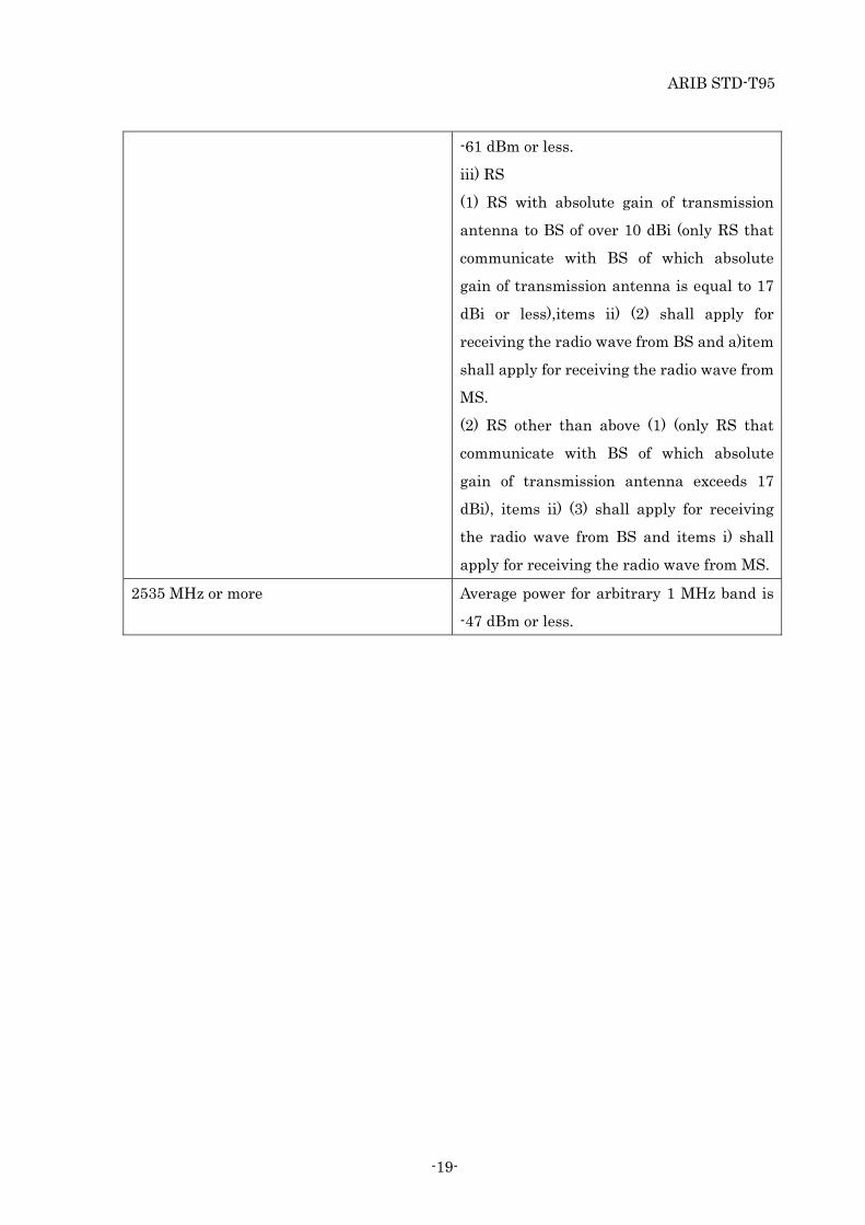
(3) MS other than above (1) and (2) (only a
MS that communicate with BS of which
absolute gain of transmission antenna
exceeds 17 dBi)
Average power for arbitrary 1 MHz band is
ARIB STD-T95
-19-
-61 dBm or less.
iii) RS
(1) RS with absolute gain of transmission
antenna to BS of over 10 dBi (only RS that
communicate with BS of which absolute
gain of transmission antenna is equal to 17
dBi or less),items ii) (2) shall apply for
receiving the radio wave from BS and a)item
shall apply for receiving the radio wave from
MS.
(2) RS other than above (1) (only RS that
communicate with BS of which absolute
gain of transmission antenna exceeds 17
dBi), items ii) (3) shall apply for receiving
the radio wave from BS and items i) shall
apply for receiving the radio wave from MS.
2535 MHz or more Average power for arbitrary 1 MHz band is
-47 dBm or less.
ARIB STD-T95
-20-
Chapter 3 Physical and MAC Layer Specifications
In this chapter, Physical and MAC layer of Next Generation PHS in Japan is specified.
This specification is defined by following Attachment 3.
Attachment 3: “Next Generation PHS Specifications”
This Attachment 3 is reproduced from "A-GN4.00-02-TS “Next Generation PHS
Specifications” which is standardized by XGP Forum.
This Attachment 3 is reproduced without any modification from original document.

ARIB STD-T95
-21-
Chapter 4 Japanese specific matters
In this chapter, it is listed the items of Attachment 3 which are not adopted by ARIB standard.
The following items are not reproduced in this standard because they do not comply with the
Japanese Regulations.
Table 4.1 Points of difference
Attachment 3
section number
Marks
2.3.1 There is a description of 22.5/25/30 MHz system bandwidth.
2.3.4 There is a description of 22.5/25/30 MHz system bandwidth.
2.4.1 Table 2.2, there is a description of 22.5/25/30 MHz system bandwidth in
“Number of subchannels”.
2.4.3.2 Figure 2.8, there is an expression of 20 MHz system bandwidth.
2.5 Figure 2.11, m equal 22/24/27/28/29/30 express 22.5/25/30 MHz system
bandwidth.
Table 2.3, there is a description of 22/5,25/30 MHz system bandwidth.
2.6 Figure 2.12, m equal 22/24/27/28/29/30 express 22.5/25/30 MHz system
bandwidth
3.2.3 Table 3.1, there is a description of 22.5/25/30 MHz system bandwidth.
5.5.6.1.2 “Assignment PRU Number = 128” express 30MHz system bandwidth
5.5.6.1.3 “Assignment PRU Number = 128” express 30MHz system bandwidth
5.5.6.1.4 “Assignment PRU Number = 128” express 30MHz system bandwidth
5.5.6.1.5 “Assignment PRU Number = 128” express 30MHz system bandwidth
5.5.6.1.6 “Assignment PRU Number = 128” express 30MHz system bandwidth
7.3.3.6 “SCH = 128” in MAP Origin express 30MHz system bandwidth
7.3.3.7 “SCH = 128” in MAP Origin express 30MHz system bandwidth
7.3.3.8 “SCH = 128” in MAP Origin express 30MHz system bandwidth
7.3.3.15 “Assignment PRU Number = 128” express 30MHz system bandwidth
“SCH = 128” in MAP Origin express 30MHz system bandwidth
7.3.3.22 “SCH = 128” in MAP Origin express 30MHz system bandwidth

ARIB STD-T95
-22-
Chapter 5 Measurement Method
As for the items stipulated in Ordinance Concerning Technical Regulations Conformity
Certification etc. of Specified Radio Equipment Appendix Table No.1 item 1(3), measurement
methods are specified by MIC Notification (Note) or a method that surpasses or is equal to the
method.
Note: This Notification refers to MIC Notification No.88 “The Testing Method for the
Characteristics Examination” (January 26, 2004) as of the date of the revision of this standard
version 2.0 (issued at July, 2011). Thereafter, the latest version of Notification would be applied
if this Notification or contents of this Notification would be revised.
AR
IB S
TD
-T95
AT
1-1
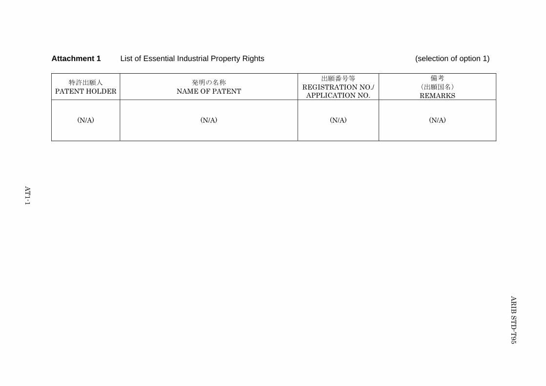
Attachment 1 List of Essential Industrial Property Rights (selection of option 1)
特許出願人 PATENT HOLDER
発明の名称 NAME OF PATENT
出願番号等 REGISTRATION NO./
APPLICATION NO.
備考 (出願国名) REMARKS
(N/A)
(N/A)
(N/A)
(N/A)


AT
2-1
AR
IB S
TD
-T95
Attachment 2 List of Essential Industrial Property Rights (selection of option 2)
特許出願人 PATENT HOLDER
発明の名称 NAME OF PATENT
出願番号等 REGISTRATION NO./APPLICATION NO.
備考 (出願国名) REMARKS
Hitachi, Ltd.*10 A comprehensive confirmation form has been submitted with regard to ARIB STD-T95 Ver.1.0
KYOCERA*10 A comprehensive confirmation form has been submitted with regard to ARIB STD-T95 Ver.1.0
NetIndex Inc. *10 A comprehensive confirmation form has been submitted with regard to ARIB STD-T95 Ver.1.0
NTT DoCoMo Inc.*10 A comprehensive confirmation form has been submitted with regard to ARIB STD-T95 Ver.1.0
Oki Electric Industry Co.,Ltd.*10
A comprehensive confirmation form has been submitted with regard to ARIB STD-T95 Ver.1.0
Qualcomm Inc.*10 A comprehensive confirmation form has been submitted with regard to ARIB STD-T95 Ver.1.0
SANYO Electric Co.;Ltd*10.
A comprehensive confirmation form has been submitted with regard to ARIB STD-T95 Ver.1.0
WILLCOM Inc.*10 A comprehensive confirmation form has been submitted with regard to ARIB STD-T95 Ver.1.0
*10:These patents are applied to the part defined by ARIB STD-T95 Ver.1.0.

AR
IB S
TD
-T95
AT
2-2
Approved by the 70th Standard Assembly Attachment 2 List of Essential Industrial Property Rights (selection of option 2)
特許出願人 PATENT HOLDER
発明の名称 NAME OF PATENT
出願番号等 REGISTRATION NO./APPLICATION NO.
備考 (出願国名) REMARKS
TOSHIBA CORPORATION.*10
A comprehensive confirmation form has been submitted with regard to ARIB STD-T95 Ver.1.0
*10:These patents are applied to the part defined by ARIB STD-T95 Ver.1.0.

AT
2-3
AR
IB S
TD
-T95
Attachment 2 List of Essential Industrial Property Rights (selection of option 2)
特許出願人 PATENT HOLDER
発明の名称 NAME OF PATENT
出願番号等 REGISTRATION NO./APPLICATION NO.
備考 (出願国名) REMARKS
㈱日立コミュニケーシ
ョンテクノロジー *10
インタリーブ方法及び無線通信装置 特願2007-223384
*10:These patents are applied to the part defined by ARIB STD-T95 Ver.1.0.

AR
IB S
TD
-T95
AT
2-4
Approved by the 73rd Standard Assembly Attachment 2 List of Essential Industrial Property Rights (selection of option 2)
特許出願人 PATENT HOLDER
発明の名称 NAME OF PATENT
出願番号等 REGISTRATION NO./APPLICATION NO.
備考 (出願国名) REMARKS
QUALCOMM Incorporated *10
Synchronized Pilot Reference Transmission for a Wireless Communication System Reducing radio link supervision time in a high data rate system A method and an apparatus for a quick retransmission of signals in a communication system Method and apparatus for fast closed-loop rate adaptation in a high rate packet data transmission Method and apparatus for controlling data rate in a wireless communication system Method and Apparatus for High Rate Packet Data and Low Delay Data Transmissions
JP2003-529971 JP2003-524965 JP2003-533078 JP2004-515932 JP2005-507208 JP 2004-514369
US 20080008136, US 7,289,473, BR, CN, DE, EP, ES, FI, FR, GB, HK, IT, KR, SE, WO AU, BR, CA, CN, DE, EP, FI, FR, GB, HK, ID, IL, IN, KR, MX, NO, RU, SE, SG, TW, UA, US, WO US 6,694,469, US 7,127,654, US 20070168825, AU, BR, CA, CN, EP, HK, ID, IL, IN, KR, MX, NO, WO, RU, SG, TW, UA US 7,245,594, US 20070064646, US 20070263655, AU, BR, CA, CN, EP, HK, ID, IL, IN, JP, KR, MX, NO, RU, SG, TW, UA, WO US, CN, DE, EP, ES, FI, FR, GB, IT, KR, SE, SG, TW, WO US 7,068,683, US 20060187877, AU, BR, CA, CN, EP, HK, ID, IL, IN, KR, MX, NO, RU, SG, TW, UA, WO
*10:These patents are applied to the part defined by ARIB STD-T95 Ver.1.0.
AT
2-5
AR
IB S
TD
-T95
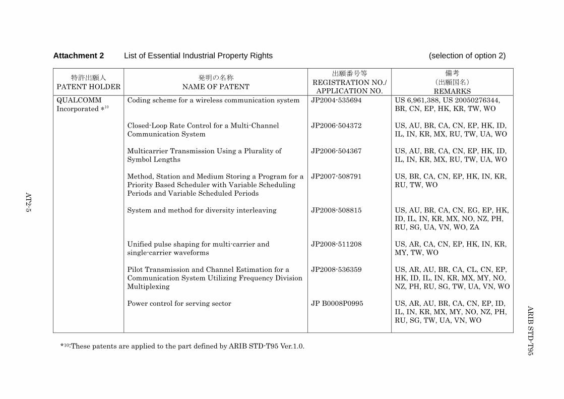
Attachment 2 List of Essential Industrial Property Rights (selection of option 2)
特許出願人 PATENT HOLDER
発明の名称 NAME OF PATENT
出願番号等 REGISTRATION NO./APPLICATION NO.
備考 (出願国名) REMARKS
QUALCOMM Incorporated *10
Coding scheme for a wireless communication system Closed-Loop Rate Control for a Multi-Channel Communication System Multicarrier Transmission Using a Plurality of Symbol Lengths Method, Station and Medium Storing a Program for a Priority Based Scheduler with Variable Scheduling Periods and Variable Scheduled Periods System and method for diversity interleaving Unified pulse shaping for multi-carrier and single-carrier waveforms Pilot Transmission and Channel Estimation for a Communication System Utilizing Frequency Division Multiplexing Power control for serving sector
JP2004-535694 JP2006-504372 JP2006-504367 JP2007-508791 JP2008-508815 JP2008-511208 JP2008-536359 JP B0008P0995
US 6,961,388, US 20050276344, BR, CN, EP, HK, KR, TW, WO US, AU, BR, CA, CN, EP, HK, ID, IL, IN, KR, MX, RU, TW, UA, WO US, AU, BR, CA, CN, EP, HK, ID, IL, IN, KR, MX, RU, TW, UA, WO US, BR, CA, CN, EP, HK, IN, KR, RU, TW, WO US, AU, BR, CA, CN, EG, EP, HK, ID, IL, IN, KR, MX, NO, NZ, PH, RU, SG, UA, VN, WO, ZA US, AR, CA, CN, EP, HK, IN, KR, MY, TW, WO US, AR, AU, BR, CA, CL, CN, EP, HK, ID, IL, IN, KR, MX, MY, NO, NZ, PH, RU, SG, TW, UA, VN, WO US, AR, AU, BR, CA, CN, EP, ID, IL, IN, KR, MX, MY, NO, NZ, PH, RU, SG, TW, UA, VN, WO
*10:These patents are applied to the part defined by ARIB STD-T95 Ver.1.0.

AR
IB S
TD
-T95
AT
2-6
Attachment 2 List of Essential Industrial Property Rights (selection of option 2)
特許出願人 PATENT HOLDER
発明の名称 NAME OF PATENT
出願番号等 REGISTRATION NO./APPLICATION NO.
備考 (出願国名) REMARKS
QUALCOMM Incorporated *10
Method and apparatus for sending signaling information via channel IDS Method and apparatus for efficient reporting of information in a wireless communication system Mapping of subpackets to resources in a communication system Apparatus and method for uplink power control of wireless communications A power control subsystem Apparatus and Method for Reducing Power Consumption in a Mobile Communications Receiver Channel structure for communication systems
WO07101041 WO07075744 WO08086074 WO08101053 JP2002-501689 JP3193380 JP4152584
US, BR, CA, CN, EP, IN, JP, KR, RU, SG, TW US, CN, EP, IN, JP, KR, TW US, TW US, TW US 5,991,284, CN, DE, US 6,240,071, US 20010010684, EP, FR, GB, HK, JP, KR, WO US 5,509,015, AU, BR, BG, CA, DE, DK, KP, EP, FI, FR, GB, HK, HU, IE, IL, IT, KR, MX, NL, WO, CN, RU, ZA, SE, SK US 6,377,809, US 09/503,401, US 6,167,270, US 6,526,030, AU, BR, CA, CL, RU, DE, EP, FI, FR, GB, HK, ID, IT, KR, MX, NO, WO, CN, TW, SE, SG, UA
*10:These patents are applied to the part defined by ARIB STD-T95 Ver.1.0.

AT
2-7
AR
IB S
TD
-T95
Approved by the 75th Standard Assembly Attachment 2 List of Essential Industrial Property Rights (selection of option 2)
特許出願人 PATENT HOLDER
発明の名称 NAME OF PATENT
出願番号等 REGISTRATION NO./APPLICATION NO.
備考 (出願国名) REMARKS
QUALCOMM
Incorporated *13
A comprehensive confirmation form has been submitted with regard to ARIB STD-T95
Ver.1.3.
*13: These patents are applied to the revised part of ARIB STD-T95 Ver.1.3.
AR
IB S
TD
-T95
AT
2-8
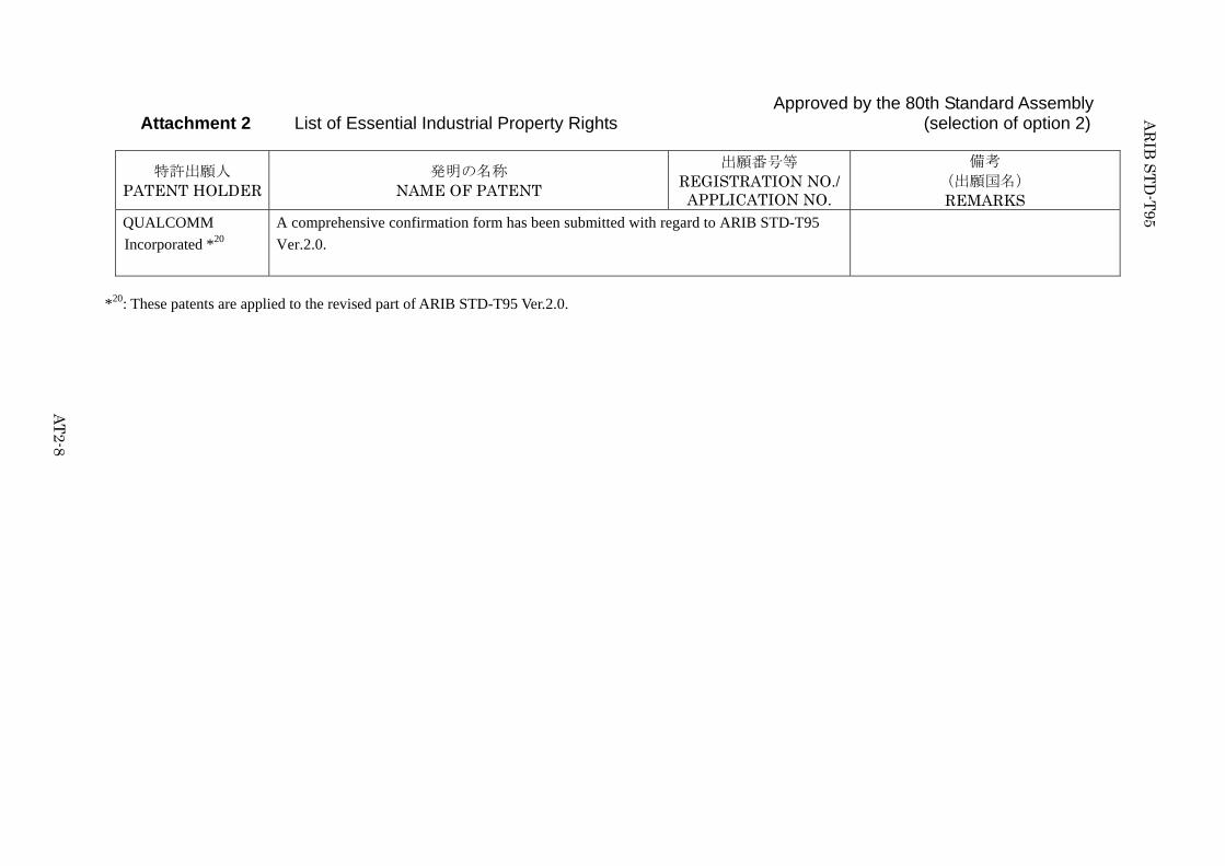
Approved by the 80th Standard Assembly Attachment 2 List of Essential Industrial Property Rights (selection of option 2)
特許出願人 PATENT HOLDER
発明の名称 NAME OF PATENT
出願番号等 REGISTRATION NO./APPLICATION NO.
備考 (出願国名) REMARKS
QUALCOMM
Incorporated *20
A comprehensive confirmation form has been submitted with regard to ARIB STD-T95
Ver.2.0.
*20: These patents are applied to the revised part of ARIB STD-T95 Ver.2.0.

ARIB STD-T95
AT2-9
Reference
This is the list of Essential Industrial Property Rights
(IPRs) filed or applied to countries other than Japan.
These are listed here as a reference, as the companies
voluntarily informed ARIB of these IPRs.
AR
IB S
TD
-T95
AT
2-10
Approved by the 73rd Standard Assembly
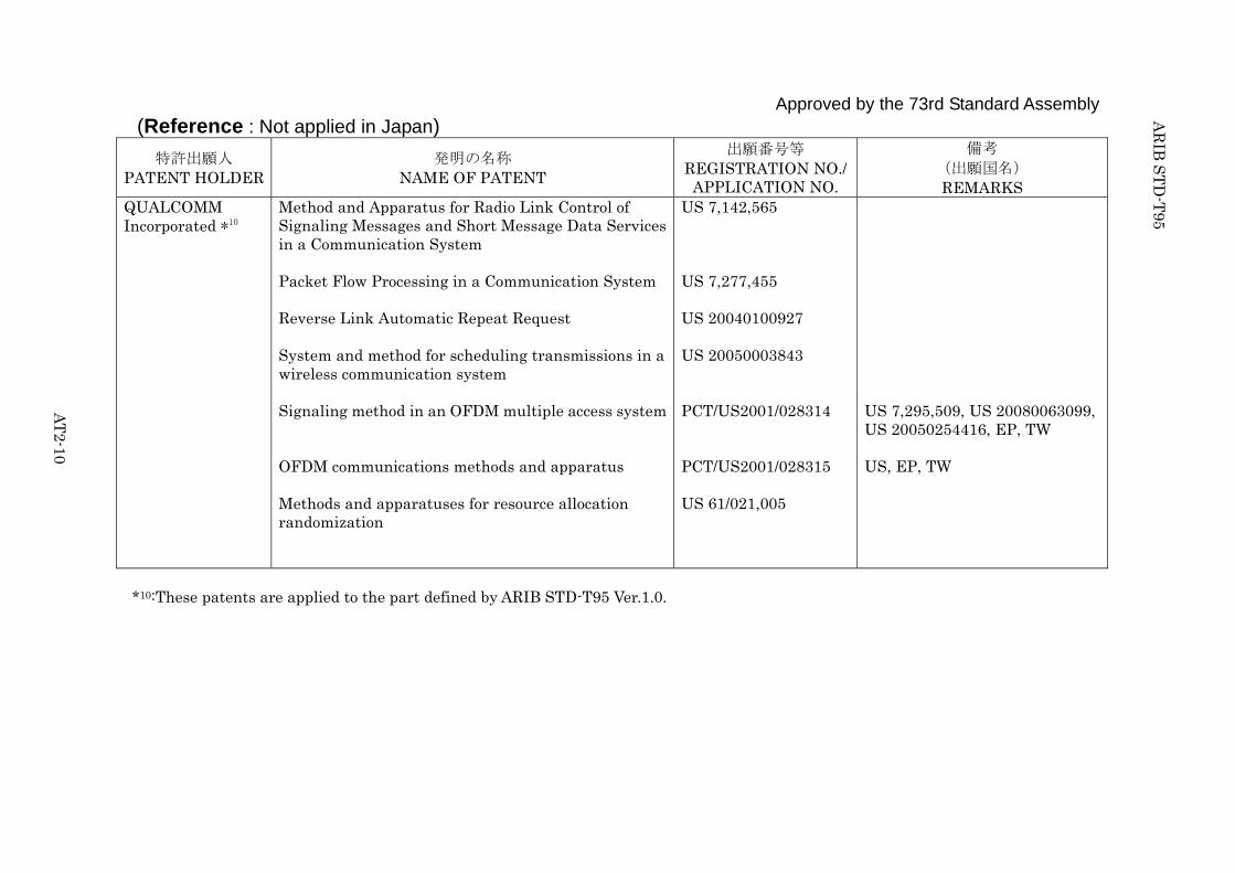
(Reference : Not applied in Japan)
特許出願人 PATENT HOLDER
発明の名称 NAME OF PATENT
出願番号等 REGISTRATION NO./APPLICATION NO.
備考 (出願国名) REMARKS
QUALCOMM Incorporated *10
Method and Apparatus for Radio Link Control of Signaling Messages and Short Message Data Services in a Communication System Packet Flow Processing in a Communication System Reverse Link Automatic Repeat Request System and method for scheduling transmissions in a wireless communication system Signaling method in an OFDM multiple access system OFDM communications methods and apparatus Methods and apparatuses for resource allocation randomization
US 7,142,565 US 7,277,455 US 20040100927 US 20050003843 PCT/US2001/028314 PCT/US2001/028315 US 61/021,005
US 7,295,509, US 20080063099, US 20050254416, EP, TW US, EP, TW
*10:These patents are applied to the part defined by ARIB STD-T95 Ver.1.0.

ARIB STD-T95
Attachment 3
Next Generation PHS
specifications
Note: This Document is reproduced without any modification from the XGP Forum
Technical Standard;”A-GN4.00-02-TS “Next Generation PHS Specifications” under the
agreement with ARIB and XGP Forum.

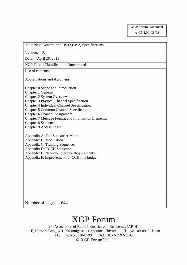
XGP Forum Document A-GN4.00-02-TS
Title: Next Generation PHS (XGP-2) Specifications
Version: 02
Date: April 26, 2011
XGP Forum Classification: Unrestricted
List of contents: Abbreviations and Acronyms. Chapter 0 Scope and Introduction. Chapter 1 General Chapter 2 System Overview.. Chapter 3 Physical Channel Specification. Chapter 4 Individual Channel Specification. Chapter 5 Common Channel Specification. Chapter 6 Channel Assignment Chapter 7 Message Format and Information Elements. Chapter 8 Sequence. Chapter 9 Access Phase. Appendix A: Full Subcarrier Mode. Appendix B: Modulation. Appendix C: Training Sequence. Appendix D: TCCH Sequence. Appendix E: Network Interface Requirements. Appendix F: Improvement for CCH link budget
Number of pages: 644
XGP Forum c/o Association of Radio Industries and Businesses (ARIB)
11F, Nittochi Bldg., 4-1, Kasumigaseki 1-choume, Chiyoda-ku, Tokyo 100-0013, Japan TEL +81-3-5510-8599 FAX +81-3-3592-1103
© XGP Forum2011
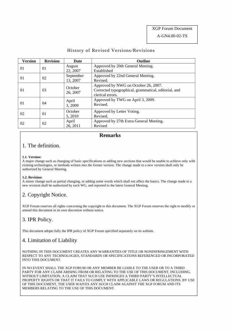
History of Revised Versions/Revisions
Version Revision Date Outline
01 01 August 22, 2007
Approved by 20th General Meeting. Established
01 02 September 13, 2007
Approved by 22nd General Meeting. Revised.
01 03 October 26, 2007
Approved by NWG on October 26, 2007. Corrected typographical, grammatical, editorial, and clerical errors.
01 04 April 3, 2009
Approved by TWG on April 3, 2009. Revised.
02 01 October 5, 2010
Approved by Letter Voting. Revised.
02 02 April 26, 2011
Approved by 27th Extra General Meeting. Revised
Remarks
1. The definition. 1.1. Version: A major change such as changing of basic specifications or adding new sections that would be unable to achieve only with existing technologies, or methods written into the former version. The change made to a new version shall only be authorized by General Meeting. 1.2. Revision: A minor change such as partial changing, or adding some words which shall not affect the basics. The change made to a new revision shall be authorized by each WG, and reported to the latest General Meeting.
2. Copyright Notice. XGP Forum reserves all rights concerning the copyright to this document. The XGP Forum reserves the right to modify or amend this document in its own discretion without notice.
3. IPR Policy. This document adopts fully the IPR policy of XGP Forum specified separately on its website.
4. Limitation of Liability NOTHING IN THIS DOCUMENT CREATES ANY WARRANTIES OF TITLE OR NONINFRINGEMENT WITH RESPECT TO ANY TECHNOLOGIES, STANDARDS OR SPECIFICATIONS REFERENCED OR INCORPORATED INTO THIS DOCUMENT. IN NO EVENT SHALL THE XGP FORUM OR ANY MEMBER BE LIABLE TO THE USER OR TO A THIRD PARTY FOR ANY CLAIM ARISING FROM OR RELATING TO THE USE OF THIS DOCUMENT, INCLUDING, WITHOUT LIMITATION, A CLAIM THAT SUCH USE INFRINGES A THIRD PARTY’S INTELLECTUAL PROPERTY RIGHTS OR THAT IT FAILS TO COMPLY WITH APPLICABLE LAWS OR REGULATIONS. BY USE OF THIS DOCUMENT, THE USER WAIVES ANY SUCH CLAIM AGAINST THE XGP FORUM AND ITS MEMBERS RELATING TO THE USE OF THIS DOCUMENT.
XGP Forum Document
A-GN4.00-02-TS
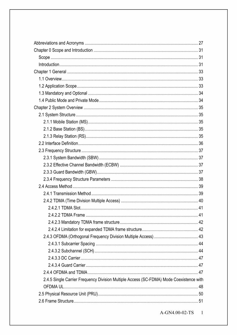
A-GN4.00-02-TS 1
Abbreviations and Acronyms ....................................................................................................... 27
Chapter 0 Scope and Introduction ............................................................................................... 31
Scope ...................................................................................................................................... 31
Introduction .............................................................................................................................. 31
Chapter 1 General ....................................................................................................................... 33
1.1 Overview ............................................................................................................................ 33
1.2 Application Scope .............................................................................................................. 33
1.3 Mandatory and Optional .................................................................................................... 34
1.4 Public Mode and Private Mode .......................................................................................... 34
Chapter 2 System Overview ........................................................................................................ 35
2.1 System Structure ............................................................................................................... 35
2.1.1 Mobile Station (MS) .................................................................................................... 35
2.1.2 Base Station (BS) ....................................................................................................... 35
2.1.3 Relay Station (RS) ...................................................................................................... 35
2.2 Interface Definition ............................................................................................................. 36
2.3 Frequency Structure .......................................................................................................... 37
2.3.1 System Bandwidth (SBW) .......................................................................................... 37
2.3.2 Effective Channel Bandwidth (ECBW) ....................................................................... 37
2.3.3 Guard Bandwidth (GBW) ............................................................................................ 37
2.3.4 Frequency Structure Parameters ............................................................................... 38
2.4 Access Method .................................................................................................................. 39
2.4.1 Transmission Method ................................................................................................. 39
2.4.2 TDMA (Time Division Multiple Access) ...................................................................... 40
2.4.2.1 TDMA Slot........................................................................................................... 41
2.4.2.2 TDMA Frame ...................................................................................................... 41
2.4.2.3 Mandatory TDMA frame structure ....................................................................... 42
2.4.2.4 Limitation for expanded TDMA frame structure ................................................... 42
2.4.3 OFDMA (Orthogonal Frequency Division Multiple Access) ........................................ 43
2.4.3.1 Subcarrier Spacing ............................................................................................. 44
2.4.3.2 Subchannel (SCH) .............................................................................................. 44
2.4.3.3 DC Carrier ........................................................................................................... 47
2.4.3.4 Guard Carrier ...................................................................................................... 47
2.4.4 OFDMA and TDMA .................................................................................................... 47
2.4.5 Single Carrier Frequency Division Multiple Access (SC-FDMA) Mode Coexistence with OFDMA UL .......................................................................................................................... 48
2.5 Physical Resource Unit (PRU) ........................................................................................... 50
2.6 Frame Structure ................................................................................................................. 51
2 A-GN4.00-02-TS
2.7 Full Subcarrier Mode ......................................................................................................... 53
2.8 Multiple Input and Multiple Output Control ......................................................................... 53
2.9 Protocol Model ................................................................................................................... 54
2.9.1 Link Establishment Phase .......................................................................................... 54
2.9.2 Access Establishment Phase ..................................................................................... 54
2.9.3 Access Phase ............................................................................................................ 54
2.9.4 Optional Protocol Model ............................................................................................. 54
2.9.4.1 User plane........................................................................................................... 54
2.9.4.2 Control plane ....................................................................................................... 54
2.10 Correspondence of PRU, Function Channel and Physical Channel ................................ 56
2.11 Service Description .......................................................................................................... 58
2.12 Protocol Structure ............................................................................................................ 58
Chapter 3 Physical Channel Specification ................................................................................... 59
3.1 Overview ............................................................................................................................ 59
3.2 The General Conditions for OFDM PHY Layer .................................................................. 60
3.2.1 OFDM Burst Structure ................................................................................................ 60
3.2.2 OFDM Symbol Structure for 37.5 kHz subcarrier spacing .......................................... 60
3.2.2.1 Guard Interval ..................................................................................................... 61
3.2.2.2 Windowing .......................................................................................................... 61
3.2.3 OFDM Parameters for 37.5 kHz subcarrier spacing ................................................... 62
3.3 The General Conditions for SC PHY Layer ....................................................................... 65
3.3.1 SC Burst Structure ..................................................................................................... 65
3.3.2 SC Block Structure ..................................................................................................... 65
3.3.2.1 Guard Interval ..................................................................................................... 65
3.3.2.2 Pulse Shaping Filter ............................................................................................ 66
3.3.3 SC Parameters ........................................................................................................... 67
3.4 DL OFDM PHY Layer ........................................................................................................ 68
3.4.1 Channel Coding for PHY Frame ................................................................................. 68
3.4.1.1 CRC .................................................................................................................... 69
3.4.1.2 Scrambling .......................................................................................................... 70
3.4.1.3 Encoding ............................................................................................................. 72
3.4.1.3.1 Error Correction Encoding ........................................................................... 73
3.4.1.3.1.1 Convolutional Code (coding rate r=1/2) (Mandatory) ............................ 73
3.4.1.3.1.1.1 Convolutional Encoder .................................................................. 73
3.4.1.3.1.1.2 Puncturing Pattern ........................................................................ 73
3.4.1.3.1.2 Convolutional Code (coding rate r=1/3) (Optional) ............................... 74
3.4.1.3.1.2.1 Convolutional Encoder .................................................................. 74

A-GN4.00-02-TS 3
3.4.1.3.1.3 Tail Biting Convolutional Code ............................................................. 75
3.4.1.3.1.4 Turbo Code (Optional) .......................................................................... 76
3.4.1.3.1.4.1 Turbo Encoder .............................................................................. 76
3.4.1.3.1.4.2 Turbo Code Termination ............................................................... 77
3.4.1.3.1.4.3 Turbo Interleaver ........................................................................... 78
3.4.1.3.1.4.4 Puncturing pattern ......................................................................... 80
3.4.1.4 Bit-interleaving .................................................................................................... 83
3.4.1.4.1 Bit-interleaver Structure ............................................................................... 83
3.4.1.4.2 Block Interleaver Method ............................................................................. 84
3.4.1.4.3 Interleaver Parameters for OFDM ................................................................ 85
3.4.1.4.4 Output-bits after Bit-interleaver .................................................................... 89
3.4.1.4.5 Bit-interleaving and Rate matching .............................................................. 89
3.4.1.4.5.1 Bit-interleaver Structure ........................................................................ 89
3.4.1.4.5.2 Block Interleaver Method ...................................................................... 89
3.4.1.4.5.3 Output-bits after Bit-interleaver ............................................................. 90
3.4.1.5 Modulation Method ............................................................................................. 91
3.4.1.6 Precoding Method ............................................................................................... 91
3.4.1.6.1 STBC-MIMO ................................................................................................ 92
3.4.1.6.1.1 2 Layer STBC-MIMO ............................................................................ 92
3.4.1.6.1.2 4 Layer STBC-MIMO ............................................................................ 92
3.4.1.6.2 SM-MIMO .................................................................................................... 92
3.4.1.6.2.1 2 Layer SM-MIMO ................................................................................ 93
3.4.1.6.2.2 4 Layer SM-MIMO ................................................................................ 93
3.4.1.6.3 EMB-MIMO .................................................................................................. 94
3.4.1.6.3.1 Transmission Weight Calculation ......................................................... 94
3.4.1.6.3.2 2 Layer EMB-MIMO .............................................................................. 95
3.4.1.6.3.3 4 Layer EMB-MIMO .............................................................................. 95
3.4.1.6.4 Optional Precoding Method ......................................................................... 95
3.4.1.6.4.1 Precoding for transmission on a single antenna port ............................ 95
3.4.1.6.4.2 Precoding for spatial multiplexing using antenna ports with BS-specific pilot ........................................................................................................................ 95
3.4.1.6.4.2.1 Precoding without CDD ................................................................. 96
3.4.1.6.4.2.2 Precoding for large delay CDD ..................................................... 96
3.4.1.6.4.2.3 Codebook for precoding ................................................................ 97
3.4.1.6.4.3 Precoding for transmit diversity ............................................................ 97
3.4.1.6.4.4 Precoding for spatial multiplexing using antenna ports with MS-specific pilot ........................................................................................................................ 97
4 A-GN4.00-02-TS
3.4.1.7 Symbol Mapping Method to PRU ........................................................................ 98
3.4.1.7.1 Symbol Mapping Method for CCCH, ANCH and CSCH .............................. 98
3.4.1.7.2 Symbol Mapping Method for EXCH ............................................................. 99
3.4.1.7.2.1 Symbol Mapping without DTX Symbol ................................................. 99
3.4.1.7.2.2 Symbol Mapping with DTX Symbol .................................................... 100
3.4.1.7.3 Symbol Mapping Method for MIMO ........................................................... 101
3.4.1.7.3.1 Symbol Mapping Method for STBC-MIMO ......................................... 101
3.4.1.7.3.2 Symbol Mapping Method for SM-MIMO ............................................. 101
3.4.1.7.3.3 Symbol Mapping Method for EMB-MIMO ........................................... 102
3.4.1.7.3.4 Symbol Mapping in case that p is not 0 .............................................. 102
3.4.1.7.4 Symbol Mapping Method for Retransmission of CC-HARQ ....................... 104
3.4.1.7.4.1 Symbol Mapping Method except for EMB-MIMO ............................... 104
3.4.1.7.4.2 Symbol Mapping Method for EMB-MIMO ........................................... 105
3.4.1.7.4.3 Symbol Mapping Method in case of full subcarrier mode ................... 106
3.4.1.7.5 Symbol Mapping Method to PRU for Optional Physical Channel ............... 108
3.4.1.7.5.1 Advanced Physical broadcast channel ............................................... 108
3.4.1.7.5.2 Advanced Downlink ECCH Format Indicator Channel ....................... 108
3.4.1.7.5.3 Advanced Downlink ECCH ................................................................. 109
3.4.1.7.5.4 Advanced Downlink Hybrid-ARQ Indicator Channel ........................... 110
3.4.1.8 Summary of OFDM DL Channel Coding ........................................................... 111
3.4.2 Training Format for DL OFDM .................................................................................. 112
3.4.2.1 Training Format ................................................................................................. 112
3.4.2.1.1 Training Format for ICH ............................................................................. 112
3.4.2.1.2 Training Format for CCCH ......................................................................... 112
3.4.2.2 Training Sequence ............................................................................................ 113
3.4.2.3 Training Index ................................................................................................... 113
3.4.2.3.1 Training Index for CCCH ........................................................................... 113
3.4.2.3.2 Training Index for ICH ................................................................................ 113
3.4.2.3.2.1 Training Index for SISO ...................................................................... 113
3.4.2.3.2.2 Training Index for MIMO ..................................................................... 114
3.4.2.3.2.3 Training Layer Mapping for MIMO ...................................................... 114
3.4.2.4 Advanced Synchronization Signal ..................................................................... 116
3.4.2.4.1 Advanced primary synchronization signal .................................................. 116
3.4.2.4.1.1 Sequence generation ......................................................................... 116
3.4.2.4.1.2 Mapping to resource units .................................................................. 116
3.4.2.4.2 Advanced secondary synchronization signal ............................................. 116
3.4.2.4.2.1 Sequence generation ......................................................................... 116

A-GN4.00-02-TS 5
3.4.2.4.2.2 Mapping to resource elements ........................................................... 117
3.4.3 Pilot for DL OFDM .................................................................................................... 118
3.4.3.1 Pilot for DL CCCH ............................................................................................. 118
3.4.3.2 Pilot for DL ICH ................................................................................................. 118
3.4.3.3 Optional Pilots for DL OFDM ............................................................................. 118
3.4.3.3.1 BS-specific pilots ....................................................................................... 118
3.4.3.3.1.1 Sequence generation ......................................................................... 118
3.4.3.3.1.2 Mapping to resource elements ........................................................... 119
3.4.3.3.2 MS-specific pilots ....................................................................................... 119
3.4.3.3.2.1 Sequence generation ......................................................................... 119
3.4.3.3.2.2 Mapping to resource elements ........................................................... 120
3.4.3.3.3 Positioning pilots ........................................................................................ 121
3.4.3.3.3.1 Sequence generation ......................................................................... 121
3.4.3.3.3.2 Mapping to resource elements ........................................................... 121
3.4.3.3.3.3 Positioning pilot slot configuration ...................................................... 122
3.4.4 Training and Pilot Boosting ...................................................................................... 122
3.4.4.1 1 Layer Format SISO/SDMA ............................................................................. 122
3.4.4.2 2 Layer MIMO Format except for SDMA ........................................................... 123
3.4.4.3 4 Layer MIMO Format except for SDMA ........................................................... 125
3.4.4.4 Summary for Training and Pilot Boosting .......................................................... 126
3.4.4.5 Optional Downlink Pilot boosting ....................................................................... 126
3.4.5 Signal for DL OFDM ................................................................................................. 126
3.4.5.1 Encoding and Small Scrambling ....................................................................... 126
3.4.5.1.1 (8,4)-Hamming Coding .............................................................................. 127
3.4.5.1.2 Small Scrambling Pattern .......................................................................... 127
3.4.5.2 Modulation for Signal ........................................................................................ 128
3.4.5.3 Signal for Optional DL Physical Channel .......................................................... 128
3.4.5.3.1 Advanced Physical Broadcast Channel ..................................................... 128
3.4.5.3.1.1 Scrambling ......................................................................................... 128
3.4.5.3.1.2 Modulation .......................................................................................... 128
3.4.5.3.1.3 Layer mapping and precoding ............................................................ 129
3.4.5.3.2 Advanced Downlink ECCH Indicator Channel ........................................... 129
3.4.5.3.2.1 Scrambling ......................................................................................... 129
3.4.5.3.2.2 Modulation .......................................................................................... 129
3.4.5.3.2.3 Layer mapping and precoding ............................................................ 129
3.4.5.3.3 Advanced Downlink ECCH ........................................................................ 130
3.4.5.3.3.1 ADECCH formats ............................................................................... 130
6 A-GN4.00-02-TS
3.4.5.3.3.2 ADECCH multiplexing and scrambling ............................................... 130
3.4.5.3.3.3 Modulation .......................................................................................... 131
3.4.5.3.3.4 Layer mapping and precoding ............................................................ 131
3.4.5.3.4 Advanced Downlink Hybrid-ARQ Indicator Channel .................................. 131
3.4.5.3.4.1 Modulation .......................................................................................... 132
3.4.5.3.4.2 Resource group alignment, layer mapping and precoding ................. 133
3.4.6 Null (DTX/DC Carrier/Guard carrier) for DL OFDM .................................................. 133
3.4.7 TCCH Format for DL OFDM ..................................................................................... 133
3.4.8 PRU Structure for DL OFDM .................................................................................... 134
3.4.8.1 CCH for DL OFDM ............................................................................................ 134
3.4.8.1.1 OFDM PRU Structure for CCCH ................................................................ 134
3.4.8.1.2 ICH for DL OFDM ...................................................................................... 135
3.4.8.1.2.1 OFDM PRU Structure for ANCH ........................................................ 135
3.4.8.1.3 OFDM PRU Structure for EXCH ................................................................ 140
3.4.8.1.4 OFDM PRU Structure for CSCH ................................................................ 149
3.5 UL OFDM PHY Layer ...................................................................................................... 150
3.5.1 Channel Coding for PHY Frame ............................................................................... 150
3.5.1.1 CRC .................................................................................................................. 150
3.5.1.2 Scrambling ........................................................................................................ 150
3.5.1.3 Encoding ........................................................................................................... 150
3.5.1.4 Bit-interleaving .................................................................................................. 151
3.5.1.5 Modulation Method ........................................................................................... 151
3.5.1.6 Precoding Method ............................................................................................. 151
3.5.1.6.1 MS Transmission Antenna Switching ........................................................ 151
3.5.1.7 Symbol Mapping Method to PRU ...................................................................... 152
3.5.1.8 Summary of OFDM UL Channel Coding ........................................................... 152
3.5.1.9 Training for UL OFDM ....................................................................................... 152
3.5.1.10 UL Training Sequence for MS transmission frame antenna switching ............ 152
3.5.1.11 UL Training Sequence for MS transmission slot antenna switching ................ 152
3.5.2 Pilot for UL OFDM .................................................................................................... 152
3.5.3 Signal for UL OFDM ................................................................................................. 152
3.5.4 Null (DTX/DC Carrier/Guard Carrier) for UL OFDM ................................................. 152
3.5.5 TCCH Format for UL OFDM ..................................................................................... 153
3.5.5.1 TCCH Format .................................................................................................... 153
3.5.5.2 TCCH Sequence and TCCH Sub-slot ............................................................... 153
3.5.6 PRU Structure for UL OFDM .................................................................................... 154
3.5.6.1 CCH for UL OFDM ............................................................................................ 154

A-GN4.00-02-TS 7
3.5.6.1.1 OFDM PRU Structure for CCCH ................................................................ 154
3.5.6.1.2 OFDM PRU Structure for TCCH ................................................................ 154
3.5.6.2 ICH for UL OFDM ............................................................................................. 156
3.5.6.2.1 OFDM PRU Structure for ANCH ................................................................ 156
3.5.6.2.2 OFDM PRU Structure for EXCH ................................................................ 156
3.5.6.2.3 OFDM PRU Structure for CSCH ................................................................ 159
3.6 UL SC PHY Layer ............................................................................................................ 159
3.6.1 Channel Coding for PHY Frame ............................................................................... 159
3.6.1.1 CRC .................................................................................................................. 160
3.6.1.2 Scrambling ........................................................................................................ 160
3.6.1.3 Encoding ........................................................................................................... 161
3.6.1.4 Bit-interleaving .................................................................................................. 161
3.6.1.4.1 Bit-interleaver Structure ............................................................................. 161
3.6.1.4.2 Block Interleaver Method ........................................................................... 161
3.6.1.4.3 Interleaver Parameters for UL SC .............................................................. 161
3.6.1.4.4 Rate Matching Method ............................................................................... 163
3.6.1.4.5 Output-bits After Bit-interleaver ................................................................. 170
3.6.1.5 Modulation Method ........................................................................................... 171
3.6.1.6 Symbol Mapping Method for Data Block ........................................................... 171
3.6.1.6.1 Data Block ................................................................................................. 172
3.6.1.6.2 Data Block with Virtual GI Extension ......................................................... 172
3.6.1.7 Symbol Mapping Method for SC Burst .............................................................. 174
3.6.1.7.1 Symbol Mapping Method without DTX Symbol .......................................... 174
3.6.1.7.1.1 Symbol Mapping Method with DTX Symbol ....................................... 175
3.6.1.7.2 Symbol Mapping Method for Retransmission (CC-HARQ) ........................ 175
3.6.1.8 Summary of SC UL Channel Coding ................................................................ 177
3.6.1.9 Optional Channel Coding for PHY Frame ......................................................... 178
3.6.1.9.1 CRC ........................................................................................................... 178
3.6.1.9.2 Channel coding .......................................................................................... 178
3.6.1.9.2.1 Tail biting convolutional coding ........................................................... 178
3.6.1.9.2.2 Turbo coding ...................................................................................... 178
3.6.1.9.3 Rate matching ........................................................................................... 179
3.6.1.9.4 Code block concatenation ......................................................................... 179
3.6.1.9.5 Channel Coding of UL Channels ............................................................... 179
3.6.1.9.5.1 Coding of data and control information on AUEDCH .......................... 179
3.6.1.9.5.2 Coding of Uplink control information on AUANCH .............................. 179
3.6.1.9.5.3 Uplink control information on AUEDCH without traffic data ................ 180

8 A-GN4.00-02-TS
3.6.2 Training for UL SC .................................................................................................... 180
3.6.2.1 Training Block Format ....................................................................................... 180
3.6.2.1.1 Training Format for ICH ............................................................................. 180
3.6.2.1.2 Training Format for CCCH ......................................................................... 181
3.6.2.2 Training Sequence ............................................................................................ 181
3.6.2.3 Training Index ................................................................................................... 181
3.6.2.3.1 Training Index for CCCH ........................................................................... 181
3.6.2.3.2 Training Index for ICH ................................................................................ 182
3.6.3 Pilot for UL SC ......................................................................................................... 182
3.6.3.1 Pilot Index ......................................................................................................... 183
3.6.3.2 Pilot for CCCH .................................................................................................. 183
3.6.3.3 Pilot for ICH ....................................................................................................... 183
3.6.3.3.1 Pilot for ANCH ........................................................................................... 183
3.6.3.3.2 Pilot for EXCH ........................................................................................... 183
3.6.3.3.3 Pilot for CSCH ........................................................................................... 184
3.6.3.4 Advanced Optional Pilot Signals ....................................................................... 184
3.6.3.4.1 Advanced Demodulation Pilot signal ......................................................... 184
3.6.3.4.1.1 Advanced Demodulation Pilot signal sequence .................................. 184
3.6.3.4.1.2 Mapping to physical resources ........................................................... 185
3.6.3.4.2 Advanced Sounding Pilot signal ................................................................ 185
3.6.3.4.2.1 Advanced Souding Pilot signal sequence .......................................... 185
3.6.3.4.3 Mapping to physical resources .................................................................. 185
3.6.4 Signal for UL SC ....................................................................................................... 186
3.6.4.1 Signal Encoding ................................................................................................ 186
3.6.4.1.1 (8,4) Hamming Encoding ........................................................................... 187
3.6.4.1.2 Small Scrambling ....................................................................................... 187
3.6.4.2 Modulation for Signal ........................................................................................ 187
3.6.5 Null (DTX) for UL SC ................................................................................................ 188
3.6.6 TCCH for UL SC ....................................................................................................... 189
3.6.6.1.1 TCCH Format ............................................................................................ 189
3.6.6.2 TCCH Sequence and TCCH Sub-slot ............................................................... 190
3.6.6.3 ATCCH for UL SC ............................................................................................. 190
3.6.6.3.1 Time and frequency structure .................................................................... 190
3.6.6.3.2 Access sequence generation ..................................................................... 192
3.6.6.3.3 Baseband signal generation ...................................................................... 193
3.6.7 SC Burst Structure for UL SC ................................................................................... 193
3.6.7.1 CCH for UL SC ................................................................................................. 193

A-GN4.00-02-TS 9
3.6.7.1.1 SC Burst Structure for CCCH .................................................................... 193
3.6.7.1.2 SC Burst Structure for TCCH ..................................................................... 194
3.6.7.2 ICH for UL SC ................................................................................................... 195
3.6.7.2.1 SC Burst Structure for ANCH .................................................................... 195
3.6.7.2.2 SC Burst Structure for EXCH ..................................................................... 196
3.6.7.2.3 SC Burst Structure for CSCH .................................................................... 199
3.6.7.3 CRC Unit for UL SC .......................................................................................... 202
3.6.7.4 Transmission Timing of SC Burst for UL SC ..................................................... 202
3.6.7.5 Optional SC Burst Structure for UL SC ............................................................. 203
Chapter 4 Individual Channel Specification ............................................................................... 204
4.1 Overview .......................................................................................................................... 204
4.1.1 Usage of PRU .......................................................................................................... 204
4.1.1.1 Common Channel (CCH) .................................................................................. 205
4.1.1.2 Individual Channel (ICH) ................................................................................... 205
4.1.1.2.1 PRU Numbering ........................................................................................ 206
4.1.1.2.2 PRU Numbering for Asymmetric frame ...................................................... 207
4.1.2 QoS Class (Access Mode) ....................................................................................... 208
4.1.2.1 Fast Access Channel Based on Map (FM-Mode) ............................................. 208
4.1.2.2 High Quality Channel Based on Carrier Sensing (QS-Mode) ............................ 208
4.1.3 XGP Protocol Outline ............................................................................................... 209
4.1.3.1 Frame Structure ................................................................................................ 209
4.1.3.2 Protocol Structure ............................................................................................. 210
4.2 Functional Channel .......................................................................................................... 212
4.2.1 Channel Composition ............................................................................................... 212
4.2.1.1 Individual Control Channel (ICCH) .................................................................... 213
4.2.1.2 EXCH Control Channel (ECCH) ........................................................................ 213
4.2.1.3 EXCH Data Channel (EDCH) ............................................................................ 213
4.2.1.4 CSCH Data Channel (CDCH) ........................................................................... 214
4.2.1.5 Traffic Channel (TCH) ....................................................................................... 214
4.2.1.6 Accompanied Control Channel (ACCH) ............................................................ 214
4.3 Optional Functional Control Channel ............................................................................... 214
4.3.1 DL Control Channel Composition ............................................................................. 215
4.3.1.1 Advanced Downlink EXCH Control Channel (ADECCH) .................................. 215
4.3.1.1.1 Function of ADECCH ................................................................................. 215
4.3.1.1.2 Blind detection for ADECCH ...................................................................... 215
4.3.1.2 Advanced Downlink ECCH Format Indicator Channel (ADEFICH) ................... 216
4.3.1.3 Advanced Downlink Hybrid-ARQ Indicator Channel (ADHICH) ........................ 216
10 A-GN4.00-02-TS
4.3.2 Uplink Control Channel Composition ........................................................................ 216
4.3.2.1 AUANCH/RCH .................................................................................................. 216
4.3.2.2 AUANCH/ACKCH ............................................................................................. 216
4.3.2.3 AUANCH/CQICH .............................................................................................. 216
4.4 PHY Layer Structure and Frame Format ......................................................................... 217
4.4.1 PHY Frame Structure ............................................................................................... 217
4.4.1.1 ANCH/ICCH ...................................................................................................... 218
4.4.1.2 ANCH/ECCH ..................................................................................................... 219
4.4.1.3 EXCH/EDCH ..................................................................................................... 220
4.4.1.3.1 PRU Combining ......................................................................................... 221
4.4.1.4 CSCH/TCH ....................................................................................................... 222
4.4.1.5 CSCH/CDCH .................................................................................................... 223
4.4.1.6 AUANCH/RCH .................................................................................................. 223
4.4.1.7 AUANCH/ACKCH ............................................................................................. 225
4.4.1.8 AUANCH/CQICH .............................................................................................. 226
4.4.2 Signal Symbol .......................................................................................................... 227
4.4.2.1 Signal Symbol Structure ................................................................................... 227
4.4.3 PHY Header ............................................................................................................. 228
4.4.3.1 PHY Header Structure ...................................................................................... 228
4.4.3.1.1 ANCH/ECCH PHY Header Structure ......................................................... 228
4.4.3.1.2 ANCH/ICCH PHY Header Structure .......................................................... 229
4.4.3.1.3 CSCH/CDCH PHY Header Structure ......................................................... 230
4.4.3.1.4 CSCH/TCH PHY Header Structure ............................................................ 230
4.4.3.1.5 ECCH PHY Header Structure .................................................................... 231
4.4.3.2 ECCH ................................................................................................................ 232
4.4.3.2.1 CRC Error Happening on the ANCH .......................................................... 232
4.4.4 PHY Payload ............................................................................................................ 234
4.4.4.1 PHY Payload Structure ..................................................................................... 234
4.4.5 PHY Trailer ............................................................................................................... 234
4.4.5.1 CRC .................................................................................................................. 234
4.4.5.2 TAIL .................................................................................................................. 234
4.4.6 PHY Control Layer ................................................................................................... 234
4.4.6.1 Channel Identifier (CI) ....................................................................................... 234
4.4.6.1.1 CI of ANCH ................................................................................................ 235
4.4.6.1.2 CI of CSCH ................................................................................................ 235
4.4.6.2 Shift Direction (SD) ........................................................................................... 235
4.4.6.3 ANCH Power Control (APC) ............................................................................. 236
A-GN4.00-02-TS 11
4.4.6.4 Power Control (PC) ........................................................................................... 236
4.4.6.5 MCS Indicator (MI) and MCS Request (MR) ..................................................... 237
4.4.6.5.1 MI and MR in ECCH .................................................................................. 238
4.4.6.5.1.1 MI Indication Timing of DL .................................................................. 240
4.4.6.5.1.2 MI Indication Timing of UL .................................................................. 241
4.4.6.5.2 MI and MR in CSCH .................................................................................. 242
4.4.6.5.2.1 MI Indication Timing of DL .................................................................. 242
4.4.6.5.2.2 MI Indication Timing of UL .................................................................. 242
4.4.6.6 Acknowledgement (ACK) .................................................................................. 243
4.4.6.6.1 ACK in ECCH ............................................................................................ 243
4.4.6.6.1.1 Response Timing of DL ACK .............................................................. 244
4.4.6.6.1.2 Response Timing of UL ACK .............................................................. 245
4.4.6.6.2 ACK in CDCH ............................................................................................ 245
4.4.6.6.2.1 Response Timing of DL ACK .............................................................. 245
4.4.6.6.2.2 Response Timing of UL ACK .............................................................. 246
4.4.6.6.3 ACK in AUANCH/ACKCH .......................................................................... 246
4.4.6.6.3.1 Response Timing of UL ACK .............................................................. 246
4.4.6.6.3.2 ACK/NACK bundling .......................................................................... 247
4.4.6.6.3.3 ACK/NACK multiplexing ..................................................................... 247
4.4.6.6.4 ACK in ADHICH ......................................................................................... 249
4.4.6.6.4.1 Response Timing of DL ACK .............................................................. 249
4.4.6.7 Channel quality report ....................................................................................... 249
4.4.6.7.1 CQI definition ............................................................................................. 250
4.4.6.7.2 PMI definition ............................................................................................. 251
4.4.6.7.3 Periodic CQI/PMI/RI reporting on CQICH .................................................. 251
4.4.6.8 MAP .................................................................................................................. 254
4.4.6.8.1 Response Timing of MAP .......................................................................... 256
4.4.6.9 Validity (V)......................................................................................................... 257
4.4.6.9.1 V Indication Timing of DL ........................................................................... 261
4.4.6.9.2 V Indication Timing of UL ........................................................................... 262
4.4.6.10 HARQ Cancel (HC) ......................................................................................... 263
4.4.6.10.1 HC Indication Timing of DL ...................................................................... 263
4.4.6.10.2 HC Indication Timing of UL ...................................................................... 265
4.4.6.11 Request Channel (RCH) ................................................................................. 266
4.4.6.11.1 UL Data Size Notification ......................................................................... 266
4.4.6.11.2 Transmission Power Margin Notification .................................................. 267
4.4.6.12 Request Channel (RCH) ................................................................................. 267

12 A-GN4.00-02-TS
4.4.6.12.1 Optional UL Data Size Notification ........................................................... 267
4.4.6.12.2 Advanced Transmission Power Margin Notification (ATPMN) Report ..... 268
4.4.6.13 ANCH MCS Indicator (AMI) ............................................................................ 269
4.4.6.14 ANCH MCS Request (AMR) ........................................................................... 270
4.4.6.15 MIMO type for EXCH (MT) .............................................................................. 270
4.4.6.16 Stream Indicator for EXCH (SI) ....................................................................... 271
4.4.6.17 MIMO type for EXCH (SR) .............................................................................. 271
4.4.6.18 Bandwidth Indicator for EXCH (BI) .................................................................. 271
4.4.7 PHY Control Layer for ADECCH .............................................................................. 273
4.4.7.1 ADECI format 0 ................................................................................................. 273
4.4.7.1.1 Flag for format0/format1A differentiation ................................................... 273
4.4.7.1.2 Hopping flag .............................................................................................. 273
4.4.7.1.3 Resource unit assignment and hopping resource allocation ...................... 273
4.4.7.1.4 Modulation and coding scheme and redundancy version .......................... 274
4.4.7.1.5 Advanced New Data Indicator (ANDI) ....................................................... 274
4.4.7.1.6 TPC command for scheduled AUEDCH .................................................... 274
4.4.7.1.7 Cyclic shift for DM RS ................................................................................ 274
4.4.7.1.8 UL index .................................................................................................... 274
4.4.7.1.9 Downlink assignment index for uplink control signaling ............................. 275
4.4.7.1.10 CQI request ............................................................................................. 275
4.4.7.2 ADECI format 1 ................................................................................................. 276
4.4.7.2.1 Resource allocation header ....................................................................... 276
4.4.7.2.2 Resource unit assignment ......................................................................... 276
4.4.7.2.3 Modulation and coding scheme ................................................................. 276
4.4.7.2.4 HARQ process number .............................................................................. 276
4.4.7.2.5 ANDI .......................................................................................................... 277
4.4.7.2.6 Redundancy version .................................................................................. 277
4.4.7.2.7 TPC command for AUANCH ..................................................................... 277
4.4.7.2.8 Downlink assignment index in downlink control signalling ......................... 277
4.4.7.3 ADECI format 1A .............................................................................................. 277
4.4.7.3.1 Flag for format0/format1A differentiation ................................................... 277
4.4.7.3.2 Localized/Distributed VRU assignment flag ............................................... 278
4.4.7.3.3 Resource unit assignment ......................................................................... 278
4.4.7.3.4 Modulation and coding scheme ................................................................. 278
4.4.7.3.5 HARQ process number .............................................................................. 278
4.4.7.3.6 ANDI .......................................................................................................... 278
4.4.7.3.7 Redundancy version .................................................................................. 278

A-GN4.00-02-TS 13
4.4.7.3.8 TPC command for AUANCH ..................................................................... 278
4.4.7.3.9 Downlink Assignment Index for downlink control signalling ....................... 278
4.4.7.4 ADECI format 1B .............................................................................................. 279
4.4.7.4.1 Localized/Distributed VRU assignment flag ............................................... 279
4.4.7.4.2 Resource unit assignment ......................................................................... 279
4.4.7.4.3 Modulation and coding scheme ................................................................. 279
4.4.7.4.4 HARQ process number .............................................................................. 279
4.4.7.4.5 ANDI .......................................................................................................... 279
4.4.7.4.6 Redundancy version .................................................................................. 279
4.4.7.4.7 TPC command for AUANCH ..................................................................... 279
4.4.7.4.8 Downlink Assignment Index for downlink control signalling ....................... 279
4.4.7.4.9 TPMI information for precoding ................................................................. 280
4.4.7.4.10 PMI confirmation for precoding ................................................................ 280
4.4.7.5 ADECI format 1C .............................................................................................. 280
4.4.7.5.1 Gap value .................................................................................................. 280
4.4.7.5.2 Resource unit assignment ......................................................................... 280
4.4.7.5.3 Transport block size index ......................................................................... 280
4.4.7.6 ADECI format 1D .............................................................................................. 280
4.4.7.6.1 Localized/Distributed VRU assignment flag ............................................... 281
4.4.7.6.2 Resource unit assignment ......................................................................... 281
4.4.7.6.3 Modulation and coding scheme ................................................................. 281
4.4.7.6.4 HARQ process number .............................................................................. 281
4.4.7.6.5 ANDI .......................................................................................................... 281
4.4.7.6.6 Redundancy version .................................................................................. 281
4.4.7.6.7 TPC command for AUANCH ..................................................................... 281
4.4.7.6.8 Downlink assignment index for DL control signaling .................................. 281
4.4.7.6.9 TPMI information for precoding ................................................................. 281
4.4.7.6.10 Downlink power offset .............................................................................. 282
4.4.7.7 ADECI format 2 ................................................................................................. 282
4.4.7.7.1 Resource allocation header ....................................................................... 282
4.4.7.7.2 Resource unit assignment ......................................................................... 282
4.4.7.7.3 TPC command for AUANCH ..................................................................... 282
4.4.7.7.4 Downlink assignment index for downlink control signalling ........................ 282
4.4.7.7.5 HARQ process number .............................................................................. 282
4.4.7.7.6 Transport block to codeword swap flag ..................................................... 283
4.4.7.7.7 Modulation and coding scheme ................................................................. 283
4.4.7.7.8 ANDI .......................................................................................................... 283
14 A-GN4.00-02-TS
4.4.7.7.9 Redundancy version .................................................................................. 283
4.4.7.7.10 Precoding information .............................................................................. 283
4.4.7.8 ADECI format 2A .............................................................................................. 284
4.4.7.8.1 Resource allocation header ....................................................................... 284
4.4.7.8.2 Resource unit assignment ......................................................................... 284
4.4.7.8.3 TPC command for AUANCH ..................................................................... 284
4.4.7.8.4 Downlink assignment index for downlink control signalling ........................ 284
4.4.7.8.5 HARQ process number .............................................................................. 284
4.4.7.8.6 Transport block to codeword swap flag ..................................................... 284
4.4.7.8.7 Modulation and coding scheme ................................................................. 284
4.4.7.8.8 ANDI .......................................................................................................... 285
4.4.7.8.9 Redundancy version .................................................................................. 285
4.4.7.8.10 Precoding information .............................................................................. 285
4.4.7.9 ADECI format 3 ................................................................................................. 285
4.4.7.9.1 TPC command ........................................................................................... 285
4.4.7.10 ADECI format 3A ............................................................................................ 285
4.4.7.10.1 TPC command ......................................................................................... 286
4.4.8 Summary of PHY Frame Format .............................................................................. 286
4.5 MAC Layer Structure and Frame Format ......................................................................... 288
4.5.1 Overview .................................................................................................................. 288
4.5.1.1 Format Regulations ........................................................................................... 288
4.5.1.2 MAC Frame Composition .................................................................................. 289
4.5.2 MAC Frame Format .................................................................................................. 290
4.5.2.1 MAC Frame Structure ....................................................................................... 291
4.5.2.1.1 ICCH, EDCH and CDCH ........................................................................... 291
4.5.2.1.2 TCH ........................................................................................................... 291
4.5.2.1.3 ACCH ........................................................................................................ 292
4.5.2.1.3.1 Frame Structure ................................................................................. 292
4.5.2.1.3.2 ACCH Layer 2 Frame Signal Structure .............................................. 292
4.5.2.2 MAC Header ..................................................................................................... 295
4.5.2.2.1 Each Field of MAC Header ........................................................................ 297
4.5.2.2.1.1 Frame Division Information (B) ........................................................... 297
4.5.2.2.1.2 Data Type (CD) .................................................................................. 298
4.5.2.2.1.3 Data Part Sharing (MD) ...................................................................... 298
4.5.2.2.1.4 Bit of Payload Length Identification (F) ............................................... 299
4.5.2.2.1.5 QCS-ID (QI)........................................................................................ 299
4.5.2.2.1.6 Sequence Number (N) ....................................................................... 299
A-GN4.00-02-TS 15
4.5.2.2.1.7 Index (IX) ............................................................................................ 300
4.5.2.2.1.8 Data Part Length (L) ........................................................................... 300
4.5.2.2.1.9 User Data Length (Ln) ........................................................................ 301
4.5.2.2.1.10 Information Area (DATA) .................................................................. 301
4.5.2.3 MAC Payload .................................................................................................... 301
4.5.2.3.1 Upper Layer Data ...................................................................................... 301
4.5.2.3.2 MAC Control Information ........................................................................... 302
4.5.3 Segmentation, Combining and Concatenation ......................................................... 302
4.5.3.1 Upper Layer Data Segmentation ....................................................................... 302
4.5.3.2 MAC Frame Segmentation in case of Retransmission ...................................... 303
4.5.3.3 Combining Multiple Upper Layer Data into Single MAC Payload ...................... 304
4.5.3.4 MAC Frame Concatenation ............................................................................... 305
4.5.4 Segmentation, Combining and Concatenation ......................................................... 306
4.5.5 MAC Control Layer ................................................................................................... 307
4.5.5.1 MAC Control Protocol ....................................................................................... 308
4.5.5.1.1 Receive Ready (RR) .................................................................................. 308
4.5.5.1.2 Receive Not Ready (RNR) ......................................................................... 309
4.5.5.1.3 Frame Reject (FRMR) ............................................................................... 310
4.5.5.1.4 Selective Reject (SREJ) ............................................................................ 310
4.5.5.1.5 Reject (REJ) .............................................................................................. 311
4.5.5.2 Control Operation Elements .............................................................................. 311
4.5.5.2.1 Poll bit ........................................................................................................ 311
4.5.5.2.2 Variables .................................................................................................... 312
4.5.5.2.2.1 The range of a sequence number and variable .................................. 312
4.5.5.2.2.2 Send state variable V(S) .................................................................... 312
4.5.5.2.2.3 Acknowledge state variable V(A) ........................................................ 312
4.5.5.2.2.4 Send sequence number N(S) ............................................................. 312
4.5.5.2.2.5 Receive state variable V(R) ................................................................ 312
4.5.5.2.2.6 Receive sequence number N(R) ........................................................ 312
4.5.5.2.3 Timers ........................................................................................................ 312
4.5.5.2.3.1 Response acknowledge timer T1 ....................................................... 312
4.5.5.2.3.2 Response transfer timer T2 ................................................................ 313
4.5.5.2.3.3 Peer station busy supervisory timer T3 .............................................. 313
4.5.5.2.3.4 Link alive check timer T4 .................................................................... 313
4.5.5.3 Access Establishment Phase Control Protocol ................................................. 313
4.6 Optional MAC Layer Structure and sub-layer .................................................................. 313
4.6.1 Overview .................................................................................................................. 313

16 A-GN4.00-02-TS
4.6.2 MAC sub-layer1 (MSL1) ........................................................................................... 313
4.6.3 MAC sub-layer2 (MSL2) ........................................................................................... 316
4.6.3.1 TMD PDU.......................................................................................................... 317
4.6.3.2 UMD PDU ......................................................................................................... 317
4.6.3.3 AMD PDU ......................................................................................................... 317
4.6.3.4 AMD PDU segment ........................................................................................... 318
4.6.3.5 State variables parameter and timers ............................................................... 318
4.6.4 MAC sublayer 3 (MSL3) ........................................................................................... 320
4.6.4.1 Overview ........................................................................................................... 320
4.6.4.2 UL Data Transfer Procedures ........................................................................... 321
4.6.4.3 DL Data Transfer Procedures ........................................................................... 321
4.6.4.4 MSL 3 chuck ..................................................................................................... 322
4.6.4.5 Header Compression and Decompression ....................................................... 322
4.6.4.6 Ciphering and Deciphering ................................................................................ 323
4.6.4.7 Integrity Protection and Verification .................................................................. 323
4.6.4.8 Handling of unknown, unforeseen and erroneous protocol data ....................... 323
4.6.4.9 Protocol data units, formats and parameters .................................................... 323
4.6.4.10 Formats ........................................................................................................... 324
4.6.4.10.1 General .................................................................................................... 324
4.6.4.11 Parameters ..................................................................................................... 324
4.6.4.12 State variables ................................................................................................ 324
4.6.4.13 Timers ............................................................................................................. 325
4.6.4.14 Constants ........................................................................................................ 325
Chapter 5 Common Channel Specification ................................................................................ 326
5.1 Overview .......................................................................................................................... 326
5.2 Common Channel (CCH) ................................................................................................. 326
5.2.1 Logical Common Channel (LCCH) ........................................................................... 328
5.2.2 Definition of Superframe ........................................................................................... 329
5.2.3 Superframe Structure of DL LCCH ........................................................................... 329
5.2.3.1 LCCH Interval Value (n) .................................................................................... 329
5.2.3.2 Frame Basic Unit Length (nSUB) ........................................................................ 330
5.2.3.3 Number of Same Paging Groups (nSG) ............................................................. 330
5.2.3.4 PCH Number (nPCH) .......................................................................................... 330
5.2.3.5 Paging Grouping Factor (nGROUP) ...................................................................... 330
5.2.3.6 Battery Saving Cycle Maximum value (nBS) ...................................................... 330
5.2.3.7 The Relationship Among Profile Data ............................................................... 331
5.2.3.8 Paging Group Calculation Rules ....................................................................... 331

A-GN4.00-02-TS 17
5.2.3.9 Optional Paging Group Calculation Rules ......................................................... 332
5.2.3.10 Intermittent Transmission Timing for ICH ........................................................ 332
5.2.4 Structure of UL LCCH .............................................................................................. 333
5.2.5 Structure of DL LCCH .............................................................................................. 333
5.2.6 LCCH Multiplexing .................................................................................................... 334
5.2.6.1 When PCH Paging Groups Being Independent ................................................ 335
5.2.6.2 When PCH Paging Groups Being Inter-related ................................................. 335
5.3 PHY Frame Format ......................................................................................................... 336
5.3.1 BCCH ....................................................................................................................... 336
5.3.2 PCH .......................................................................................................................... 337
5.3.3 TCCH ....................................................................................................................... 337
5.3.4 SCCH ....................................................................................................................... 337
5.3.4.1 DL SCCH .......................................................................................................... 337
5.3.4.2 UL SCCH for OFDMA ....................................................................................... 338
5.3.4.3 UL SCCH for SC ............................................................................................... 338
5.4 Control Field Format ........................................................................................................ 339
5.4.1 Channel Identifier (CI) .............................................................................................. 339
5.4.2 BS Information (BS-Info) .......................................................................................... 339
5.4.2.1 Base Station ID (BSID) ..................................................................................... 340
5.4.2.1.1 System Type .............................................................................................. 340
5.4.2.1.2 Operator ID ................................................................................................ 340
5.4.2.1.3 System Additional ID ................................................................................. 340
5.4.2.1.3.1 Paging Area Number .......................................................................... 340
5.4.2.1.3.2 Sequence Number ............................................................................. 340
5.4.2.2 BS Additional ID ................................................................................................ 340
5.4.3 Common Control Information (CCI) .......................................................................... 341
5.4.3.1 Absolute Slot Number ....................................................................................... 341
5.4.4 Mobile Station ID (MSID) .......................................................................................... 341
5.5 MSG Field ........................................................................................................................ 342
5.5.1 Message Type List ................................................................................................... 342
5.5.2 MSG (BCCH) ........................................................................................................... 343
5.5.2.1 "Radio Channel Information Broadcasting" Message........................................ 343
5.5.2.2 "System Information Broadcasting" Message ................................................... 350
5.5.2.3 "Optional Information Broadcasting" Message .................................................. 353
5.5.3 MSG (Optional BCCH) ............................................................................................. 354
5.5.3.1 MSG (BCCH) .................................................................................................... 354
5.5.4 MSG (PCH) .............................................................................................................. 355
18 A-GN4.00-02-TS
5.5.4.1 “No Paging” Message ....................................................................................... 357
5.5.4.2 "Paging Type 1" Message (single paging / 50 bits' Paging ID) .......................... 359
5.5.4.3 "Paging Type 2" Message (single paging / 34 bits' Paging ID) .......................... 361
5.5.4.4 "Paging Type 3" Message (single paging / 24 bits' Paging ID) .......................... 363
5.5.4.5 "Paging Type 4" Message (multiplex paging / 34 bits' Paging ID) ..................... 365
5.5.4.6 "Paging Type 5" Message (multiplex paging / 24 bits' Paging ID) ..................... 368
5.5.4.7 "Paging Type 6" Message (paging and LCH assignment / 34 bits' Paging ID) .. 370
5.5.4.8 "Paging Type 7" Message (paging and LCH assignment / 24 bits' Paging ID) .. 373
5.5.5 MSG (Optional PCCH) ............................................................................................. 375
5.5.6 MSG (SCCH) ........................................................................................................... 376
5.5.6.1 DL SCCH .......................................................................................................... 376
5.5.6.1.1 "Idle" Message ........................................................................................... 377
5.5.6.1.2 "LCH Assignment 1" Message ................................................................... 378
5.5.6.1.3 "LCH Assignment 2" Message ................................................................... 382
5.5.6.1.4 "LCH Assignment 3" Message ................................................................... 387
5.5.6.1.5 "LCH Assignment Standby" Message ........................................................ 392
5.5.6.1.6 "LCH Assignment Reject" Message ........................................................... 397
5.5.6.2 UL SCCH .......................................................................................................... 402
5.5.6.2.1 "LCH Assignment Re-request" Message ................................................... 403
Chapter 6 Channel Assignment ................................................................................................. 405
6.1 Overview .......................................................................................................................... 405
6.2 Link Establishment Control .............................................................................................. 405
6.3 Channel Assignment Control ........................................................................................... 407
6.4 Connection Control .......................................................................................................... 408
6.4.1 FM-Mode .................................................................................................................. 408
6.4.1.1 Connection Control ........................................................................................... 408
6.4.1.1.1 Access Timing ........................................................................................... 410
6.4.1.1.1.1 Overview ............................................................................................ 410
6.4.1.1.1.2 5ms frame unit.................................................................................... 410
6.4.1.1.1.3 2.5ms frame unit ................................................................................. 412
6.4.1.1.1.4 10ms frame unit .................................................................................. 413
6.4.1.1.1.5 MS processing capabilities ................................................................. 415
6.4.1.1.2 Bandwidth Request by MS ........................................................................ 416
6.4.1.1.3 DL EXCH Holding Duration ....................................................................... 416
6.4.1.2 Channel Selection ............................................................................................. 417
6.4.1.2.1 Vacant PRU Judgment by UL Carrier Sensing .......................................... 417
6.4.1.2.2 ANCH Allocation ........................................................................................ 418

A-GN4.00-02-TS 19
6.4.1.2.3 EXCH Allocation ........................................................................................ 418
6.4.2 QS-Mode .................................................................................................................. 419
6.4.2.1 Channel Selection ............................................................................................. 419
6.4.2.1.1 CSCH Allocation ........................................................................................ 419
6.5 Radio State Management ................................................................................................ 420
6.5.1 Idle State .................................................................................................................. 421
6.5.2 Active State .............................................................................................................. 422
6.5.3 Sleep State ............................................................................................................... 423
6.6 Optional Radio State Management .................................................................................. 424
6.6.1 Idle State .................................................................................................................. 425
6.6.2 Active State .............................................................................................................. 425
6.7 ICH continuation transmission ......................................................................................... 426
6.8 Optional Random access procedure................................................................................ 426
6.9 Summary of Parameters .................................................................................................. 428
Chapter 7 Message Format and Information Elements .............................................................. 430
7.1 Overview .......................................................................................................................... 430
7.2 Message Format .............................................................................................................. 430
7.2.1 Format Regulations .................................................................................................. 430
7.2.2 Message Type .......................................................................................................... 431
7.2.2.1 Link Setup Request ........................................................................................... 432
7.2.2.2 Link Setup Request (SC) .................................................................................. 433
7.2.2.3 Link Setup Response ........................................................................................ 434
7.2.2.4 Extension Function Request ............................................................................. 435
7.2.2.5 Extension Function Response .......................................................................... 436
7.2.2.6 Connection Request ......................................................................................... 437
7.2.2.7 Connection Response ....................................................................................... 438
7.2.2.8 ANCH/CSCH Switching Confirmation ............................................................... 439
7.2.2.9 ANCH/CSCH Switching Indication .................................................................... 440
7.2.2.10 ANCH/CSCH Switching Request .................................................................... 441
7.2.2.11 ANCH/CSCH Switching Rejection .................................................................. 442
7.2.2.12 ANCH/CSCH Switching Re-request ................................................................ 443
7.2.2.13 TDMA Slot Limitation Request ........................................................................ 444
7.2.2.14 CQI Report ...................................................................................................... 444
7.2.2.15 CQI Report Indication ..................................................................................... 445
7.2.2.16 Additional LCH Confirmation ........................................................................... 445
7.2.2.17 Additional LCH Indication ................................................................................ 446
7.2.2.18 Additional QCS Request ................................................................................. 446
20 A-GN4.00-02-TS
7.2.2.19 Additional QCS Request Indication ................................................................. 447
7.2.2.20 Additional QCS Response .............................................................................. 447
7.2.2.21 Additional QCS Rejection ................................................................................ 448
7.2.2.22 Additional QCS Re-request ............................................................................. 448
7.2.2.23 Connection Release ........................................................................................ 449
7.2.2.24 Connection Release Acknowledgement .......................................................... 450
7.2.2.25 QCS Release .................................................................................................. 450
7.2.2.26 QCS Release Acknowledgement .................................................................... 451
7.2.2.27 Authentication Information 1 ........................................................................... 451
7.2.2.28 Authentication Information 2 ........................................................................... 452
7.2.2.29 Encryption Key Indication ................................................................................ 452
7.2.2.30 QCS Status Enquiry Response ....................................................................... 453
7.2.2.31 QCS Status Enquiry Request .......................................................................... 453
7.3 Information Element Format ............................................................................................ 454
7.3.1 Format Regulations .................................................................................................. 454
7.3.2 Single Octet Information Element Identifier .............................................................. 455
7.3.2.1 Channel Type .................................................................................................... 455
7.3.2.2 Connection Type ............................................................................................... 456
7.3.2.3 Extension Function Sequence .......................................................................... 456
7.3.2.4 Result of Location Registration ......................................................................... 457
7.3.2.5 TDMA Slot Specification ................................................................................... 458
7.3.3 Multiple Octet Information Element Identifier ............................................................ 459
7.3.3.1 Area Information ............................................................................................... 461
7.3.3.2 Authentication Information 1 ............................................................................. 464
7.3.3.2.1 Authentication Data 1 (Authentication method Request) ........................... 464
7.3.3.2.2 Authentication Data 1 (Authentication method Acknowledge) ................... 465
7.3.3.2.3 Authentication Data 1 (Transparent control information) ........................... 465
7.3.3.2.4 Authentication Data 1 (Encryption Indication) ............................................ 466
7.3.3.3 Authentication Information 2 ............................................................................. 467
7.3.3.3.1 Authentication Data 2 (Authentication method Response) ........................ 468
7.3.3.3.2 Authentication Data 2 (Transparent control information) ........................... 469
7.3.3.3.3 Authentication Data 2 (Re-Authentication Request) .................................. 469
7.3.3.3.4 Authentication Data 2 (Encryption Request) .............................................. 469
7.3.3.4 Cause ............................................................................................................... 470
7.3.3.5 CCH Superframe Configuration ........................................................................ 472
7.3.3.6 Communication Parameter ............................................................................... 477
7.3.3.7 Connection-ID ................................................................................................... 482
A-GN4.00-02-TS 21
7.3.3.8 CQI ................................................................................................................... 482
7.3.3.9 Disconnection Type .......................................................................................... 484
7.3.3.10 Encryption Key Set ......................................................................................... 485
7.3.3.11 Extension Function Number ............................................................................ 485
7.3.3.12 MS Performance ............................................................................................. 487
7.3.3.13 MSID ............................................................................................................... 493
7.3.3.14 Protocol Version .............................................................................................. 495
7.3.3.15 PRU Information ............................................................................................. 495
7.3.3.16 QCS Information ............................................................................................. 497
7.3.3.17 QoS ................................................................................................................. 498
7.3.3.18 QCS Status ..................................................................................................... 498
7.3.3.19 Scheduling Information ................................................................................... 500
7.3.3.20 Source BS-info ................................................................................................ 501
7.3.3.21 Target BS-info ................................................................................................. 502
7.3.3.22 MAP Origin ...................................................................................................... 502
7.3.3.23 MSID (SC) ....................................................................................................... 503
7.3.3.24 Power Report .................................................................................................. 506
7.3.3.25 Report Indication ............................................................................................. 506
7.3.3.26 Encryption Key Information ............................................................................. 507
7.3.3.27 MIMO Information ........................................................................................... 507
7.3.3.28 ICH Continuation Transmission Information .................................................... 509
7.3.4 Information Element Rules ....................................................................................... 510
7.3.4.1 Error process .................................................................................................... 510
7.3.4.1.1 Protocol Identifier ....................................................................................... 510
7.3.4.1.2 Incomplete message .................................................................................. 510
7.3.4.1.3 Unexpected message type or message sequence error ............................ 510
7.3.4.1.4 Mandatory information element error ......................................................... 510
7.3.4.1.4.1 Missing mandatory information element ............................................. 510
7.3.4.1.4.2 Invalid mandatory information element ............................................... 510
7.3.4.1.4.3 Unexpected mandatory information element ...................................... 511
7.3.4.1.4.4 Unrecognized mandatory information element ................................... 511
7.3.4.1.5 Optional information element error ............................................................ 511
7.3.4.2 Information elements order ............................................................................... 511
7.3.4.3 Duplicated information elements ....................................................................... 512
Chapter 8 Sequence .................................................................................................................. 513
8.1 Overview .......................................................................................................................... 513
8.2 Sequence ........................................................................................................................ 513
22 A-GN4.00-02-TS
8.2.1 Outgoing Call ........................................................................................................... 513
8.2.2 Incoming Call ........................................................................................................... 515
8.2.3 Release .................................................................................................................... 517
8.2.3.1 Connection Release .......................................................................................... 517
8.2.3.1.1 Connection Release from MS .................................................................... 517
8.2.3.1.2 Connection Release from BS .................................................................... 518
8.2.3.2 QCS Release .................................................................................................... 518
8.2.3.2.1 QCS Release Triggered by MS ................................................................. 518
8.2.3.2.2 QCS Release Triggered by BS .................................................................. 519
8.2.4 Location Registration ................................................................................................ 520
8.2.5 ANCH/CSCH Switching ............................................................................................ 522
8.2.5.1 ANCH/CSCH Switching Triggered by MS ......................................................... 522
8.2.5.2 ANCH/CSCH Switching Triggered by BS .......................................................... 523
8.2.5.3 ANCH/CSCH Switching Rejection .................................................................... 524
8.2.5.4 ANCH/CSCH Switching Re-request .................................................................. 525
8.2.6 Handover .................................................................................................................. 526
8.2.6.1 Normal Handover Triggered by BS ................................................................... 526
8.2.6.2 Normal Handover Triggered by MS .................................................................. 528
8.2.6.3 Seamless Handover .......................................................................................... 530
8.2.7 Link Channel Establishment ..................................................................................... 532
8.2.7.1 Link Channel Assignment ................................................................................. 532
8.2.7.2 Link Channel Assignment Standby ................................................................... 532
8.2.7.3 Link Channel Re-request Sequence ................................................................. 533
8.2.7.4 Link Channel Request Standby and Link Channel Assignment Re-request ...... 533
8.2.7.5 Link Channel Assignment Rejection ................................................................. 534
8.2.8 Additional QCS ......................................................................................................... 535
8.2.8.1 Additional QCS ................................................................................................. 535
8.2.8.2 Additional QCS Request Indication ................................................................... 535
8.2.8.3 Additional QCS Rejection.................................................................................. 536
8.2.8.4 Additional QCS with Extra LCH ......................................................................... 536
8.2.8.5 Additional QCS with Re-request of Extra LCH .................................................. 537
8.2.9 Status Check ............................................................................................................ 538
8.2.9.1 QCS Status Check Triggered by MS ................................................................ 538
8.2.9.2 QCS Status Check Triggered by BS ................................................................. 538
8.2.10 CQI Transmission ................................................................................................... 539
8.2.10.1 CQI Report ...................................................................................................... 539
8.2.10.2 CQI Report Indication ..................................................................................... 539

A-GN4.00-02-TS 23
8.3 Radio Connection Management Sequence ..................................................................... 539
8.3.1 Paging ...................................................................................................................... 540
8.3.2 Radio connection establishment ............................................................................... 540
8.3.2.1 Radio connectionSetupComplete ...................................................................... 541
8.3.3 Radio connection reconfiguration ............................................................................. 542
8.3.4 Radio connection re-establishment .......................................................................... 543
8.3.5 Radio connection release ......................................................................................... 544
8.3.6 Radio Link Failure .................................................................................................... 544
8.4 Optional Mobility sequence .............................................................................................. 545
8.4.1 Mobility Management in IDLE State ......................................................................... 545
8.4.1.1 Cell selection ..................................................................................................... 545
8.4.1.2 Cell reselection ................................................................................................. 546
8.4.2 Mobility Management in active state ........................................................................ 547
8.4.2.1 General ............................................................................................................. 547
8.4.2.2 Handover .......................................................................................................... 548
8.4.3 Measurements ......................................................................................................... 550
8.4.3.1 Intra-frequency neighbour (cell) measurements ................................................ 551
8.4.3.2 Inter-frequency neighbour (cell) measurements ................................................ 551
8.4.3.3 measurement configuration ............................................................................... 551
8.4.3.4 Measurement reporting ..................................................................................... 552
Chapter 9 Access Phase ........................................................................................................... 553
9.1 Overview .......................................................................................................................... 553
9.2 Retransmission Control Method ...................................................................................... 553
9.2.1 ARQ ......................................................................................................................... 553
9.2.1.1 Procedure of ARQ ............................................................................................. 553
9.2.1.2 Setting the Timing for Transmission of the ACK Field in CDCH ........................ 553
9.2.1.3 Timing of Retransmission .................................................................................. 554
9.2.1.4 Example of ARQ Retransmission ...................................................................... 554
9.2.1.5 Example of Sequence ....................................................................................... 555
9.2.1.6 About the Switch of ARQ and the Adaptive Modulation .................................... 556
9.2.2 HARQ ....................................................................................................................... 556
9.2.2.1 Procedure of HARQ .......................................................................................... 556
9.2.2.2 Retransmission Rule in FM-Mode ..................................................................... 557
9.2.2.3 HARQ Approval Condition ................................................................................ 559
9.2.2.4 HARQ Cancel Condition ................................................................................... 559
9.2.2.5 Setting the Timing for the Transmission of the ACK Field in the ANCH ............ 560
9.2.2.6 Timing of Retransmission .................................................................................. 562
24 A-GN4.00-02-TS
9.2.2.6.1 HARQ Retransmission Timing for High Performance MS .......................... 562
9.2.2.6.2 HARQ Retransmission Timing for Low Performance MS .......................... 563
9.2.2.7 Example of HARQ Retransmission ................................................................... 564
9.2.2.8 Example of Sequence ....................................................................................... 565
9.2.2.9 Switch of HARQ and the Adaptive Modulation .................................................. 566
9.2.2.10 Increment Redundancy (IR) Method ............................................................... 567
9.2.2.11 Retransmission Count ..................................................................................... 568
9.3 Optional Retransmission Control Method ........................................................................ 568
9.3.1 HARQ ....................................................................................................................... 568
9.3.2 ARQ ......................................................................................................................... 570
9.3.2.1 ARQ Retransmission procedure ....................................................................... 570
9.3.2.2 Polling ............................................................................................................... 572
9.3.2.3 Status report ..................................................................................................... 573
9.4 QCS and Connection ....................................................................................................... 574
9.4.1 Service Class ........................................................................................................... 576
9.4.2 QoS Parameter ........................................................................................................ 577
9.4.2.1 Forwarding Delay .............................................................................................. 577
9.4.2.2 Jitter .................................................................................................................. 577
9.4.2.3 Frame Error Rate (FER) .................................................................................... 578
9.4.2.4 Guarantee Bandwidth ....................................................................................... 578
9.4.2.5 Average Bit Rate ............................................................................................... 578
9.4.2.6 Traffic Priority .................................................................................................... 578
9.5 Access Phase Control ..................................................................................................... 579
9.5.1 Power Control .......................................................................................................... 579
9.5.2 Timing Control .......................................................................................................... 580
9.5.3 Link Adaptation Control ............................................................................................ 582
9.5.3.1 MCS Switching .................................................................................................. 582
9.5.3.1.1 Decision of Transmission MCS .................................................................. 582
9.5.3.1.2 Decision of The Reception of Demodulation MCS ..................................... 582
9.5.3.1.3 Setup of Modulation Method in MR Field for Transmission ....................... 582
9.5.4 ANCH/CSCH Scheduling Control ............................................................................. 584
9.5.5 Interference Avoidance Control ................................................................................ 585
9.5.5.1 ANCH/CSCH Disconnect Detection .................................................................. 585
9.5.5.2 ANCH/CSCH Switching .................................................................................... 586
9.5.5.2.1 MS Origin ANCH/CSCH Switching ............................................................ 587
9.5.5.2.2 BS Origin ANCH/CSCH Switching ............................................................. 588
9.5.5.2.3 Retransmission of ANCH/CSCH Switching Indication ............................... 589
A-GN4.00-02-TS 25
9.5.5.2.4 Switchback Operation ................................................................................ 589
9.5.6 Handover Control ..................................................................................................... 591
9.5.6.1 Normal Handover .............................................................................................. 591
9.5.6.2 Seamless Handover .......................................................................................... 592
9.6 MAC Layer Control .......................................................................................................... 593
9.6.1 Window Control ........................................................................................................ 593
9.6.2 Flow Control ............................................................................................................. 595
9.6.3 Retransmission Control by SR Method .................................................................... 597
9.6.4 Notification and Recovery of Error Condition............................................................ 599
9.7 Encryption Field ............................................................................................................... 600
9.8 Semi-Persistent Scheduling (SPS) .................................................................................. 600
Appendix A: Full Subcarrier Mode ............................................................................................. 601
A.1 Overview ......................................................................................................................... 601
A.2 Definition of Full Subcarrier Mode ................................................................................... 601
Appendix B: Modulation ............................................................................................................. 602
B.1 BPSK .............................................................................................................................. 602
B.2 π/2 - BPSK ...................................................................................................................... 603
B.3 QPSK .............................................................................................................................. 604
B.4 π/4 - QPSK...................................................................................................................... 605
B.5 8PSK ............................................................................................................................... 606
B.6 16QAM ............................................................................................................................ 607
B.7 64QAM ............................................................................................................................ 609
B.8 256QAM .......................................................................................................................... 612
B.9 16PSK ............................................................................................................................. 618
B.10 Optional Modulation Method ......................................................................................... 619
B.10.1 BPSK ..................................................................................................................... 619
B.10.2 QPSK ..................................................................................................................... 620
B.10.3 16QAM ................................................................................................................... 621
B.10.4 64QAM ................................................................................................................... 623
Appendix C: Training Sequence ................................................................................................ 626
C.1 OFDM Training Sequence .............................................................................................. 626
C.2 SC Training Sequence .................................................................................................... 631
Appendix D: TCCH Sequence ................................................................................................... 636
D.1 OFDM TCCH Sequence ................................................................................................. 636
D.2 SC TCCH sequence........................................................................................................ 637
Appendix E: Network Interface Requirements ........................................................................... 638
E.1 Overview ......................................................................................................................... 638

26 A-GN4.00-02-TS
E.2 Network Functions .......................................................................................................... 638
E.2.1 Paging Function ....................................................................................................... 638
E.2.1.1 Paging Area ...................................................................................................... 639
E.2.1.2 The Recognition of Paging Area ....................................................................... 639
E.2.1.3 Paging Group ................................................................................................... 640
E.2.1.4 Incoming Call .................................................................................................... 640
E.2.2 Home Location Register (HLR) Function ................................................................. 640
E.2.3 Handover Functions ................................................................................................. 641
E.2.4 Authentication Authorization Accounting (AAA) Function ........................................ 641
E.2.4.1 Authentication Procedure ................................................................................. 641
E.2.4.2 Authentication Timing ....................................................................................... 642
Appendix F: Improvement for CCH linkbudget ........................................................................... 643
F.1 Overview ......................................................................................................................... 643
F.2 Dual CCH ........................................................................................................................ 643
F.3 CCH Continuation Transmission ..................................................................................... 643

A-GN4.00-02-TS 27
Abbreviations and Acronyms
AAA Authentication, Authorization, Accounting AAS Adaptive array Antenna System ABCCH Advanced Broadcast Control Channel ACCH Accompanied Control Channel ACK Acknowledgment ACS Advanced Cyclic Shift ADC Advanced Direct Current ADECCH Advanced Downlink ECCH ADECI Advanced Downlink ECCH Control Information ADECFII Advanced Downlink ECCH Control Format Indicator Information ADEDCH Advanced Downlink EDCH ADEFICH Advanced Downlink ECCH Format Indicator Channel ADHICH Advanced Downlink Hybrid-ARQ Indicator Channel ADPCM Adaptive Differential Pulse Code Modulation AGT Advanced Guard Time al-VRC allowable Packet loss and Variable Rate Class AMI ANCH MCS Indicator AMT Advanced MIMO Type AMR ANCH MCS Request ANCH Anchor Channel ANDI Advanced New Data Indicator ATCCH Advanced Timing Correct Channel ATPMN Advanced Transmission Power Margin Notification AUANCH Advanced Uplink ANCH AUEDCH Advanced Uplink EDCH BCCH Broadcast Control Channel BER Bit Error Rate BI Bandwidth Indication BPSK Binary Phase Shift Keying BS Base Station BSID BS Identification CB Code block CC Convolutional Code CCH Common Channel CCCH Common Control Channel CC-HARQ Chase Combining -HARQ CCI Common Control Information CDCH CSCH Data Channel CI Channel Identifier CQI Channel Quality Indicator CRC Cyclic Redundancy Code CSCH Circuit Switching Channel CSI Channel State Information

28 A-GN4.00-02-TS
DSI Downlink Scheduling Index DSS Downlink Special Slot DTX Discontinuous Transmission DL DownLink ECBW Effective Channel Bandwidth ECCH EXCH Control Channel EDCH EXCH Data Channel EMB Eigen Mode Based EMI EMB-MIMO MCS Indicator EPRP Engergy Per Resource Point EXCH Extra Channel FCID Function Channel ID FER Frame Error Rate FFT Fast Fourier Transform FM-Mode Fast access channel based on MAP -Mode FRMR Frame Reject GBW Guard Bandwidth GI Guard Interval HARQ Hybrid Automatic Repeat Request HC HARQ Cancel HLR Home Location Register IBI Inter-Block Interference ICCH Individual Control Channel ICH Individual Channel ICI Inter-Carrier Interference IFFT Inverse Fast Fourier Transform IL Information Link bit IP Internet Protocol IR-HARQ Incremental Redundancy -HARQ ISI Inter-Symbol Interference LAC Leave Alone Class LCH Link Channel LCCH Logical Common Channel LD-BE Low - Delay Best Effort Class LDPC Low Density Parity Check LPF Low Pass Filter LSB Least Significant Bit MAC Media Access Control MCS Modulation and Coding Scheme MI MCS Indicator MIMO Multiple Input Multiple Output MM Mobility Management MR MCS Request MS Mobile Station MSB Most Significant Bit MSID MS Identification
A-GN4.00-02-TS 29
MT MIMO Type NACK Negative ACK NCL Neighbour Cell List NGN Next Generation Network nl-VRC no Packet loss and Variable Rate Class OFDMA Orthogonal Frequency Division Multiple Access PAD Padding PAPR Peak to Average Power Ratio PC Power Control PCH Paging Channel PDU Protocol Data Unit PHY Physical layer PLC Private Line Class PN Pseudo Noise PRU Physical Resource Unit PSP Primary Synchronization Pilot QAM Quadrature Amplitude Modulation QCS QoS Control Session QoS Quality of Service QPSK Quadrature Phase Shift Keying QS-Mode high Quality channel based on carrier Sensing -Mode RAN Radio Access Network RB Radio Bearer RCH Request Channel REJ Reject RIL Remaining Information Length indication bit RNR Receive Not Ready RP Resource Point RR Receive Ready RROF Root Roll-Off Filter RS Relay Station RSSI Received Signal Strength Indicator/Indication RT Radio frequency Transmission management RU Resource Unit SBW System Bandwidth SC Single Carrier SCCH Signaling Control Channel SC-FDMA Single Carrier Frequency Division Multiple Access SCH Subchannel SD Shift Direction SDMA Space Division Multiple Access SFBC Space Frequency Block Coding SINR Signal to Interference and Noise Ratio SI Stream Indication SISO Single Input Single Output SM Spatial Multiplexing
30 A-GN4.00-02-TS
SR Selective Repeat SR Stream Request SREJ Selective Reject SSP Secondary Synchronization Pilot STBC Space Time Block Coding SVD Singular Value Decomposition TB Transport block TCCH Timing Correct Channel TCH Traffic Channel TDD Time Division Duplex TDMA Time Division Multiple Access UL UpLink USS Uplink Special Slot V Validity VoIP Voice over IP VRC Variable Rate Class VRU Virtual Resource Unit XGP eXtended Global Platform

A-GN4.00-02-TS 31
Chapter 0 Scope and Introduction
Scope This standard is being established principally for “eXtended Global Platform (XGP)”. In order to ensure the fairness and the openness among all parties involved in developing this system, the radio equipment manufacturers, telecommunications operators and the users were invited openly to the Standard Assembly so as to gain this standard with the total agreement of all parties involved in developing standard. The scope of application of this standard covers the minimum requirements for the service and communication provided by this system. This standard of XGP is promoted by the XGP Forum (formerly PHS MoU Group, PHS means Personal Handy phone System.), PHS MoU Group was established in 1995; for the purpose of expanding PHS service to all over the world. Introduction XGP is one of the future Broadband Wireless Access systems (BWA), which will realize the high speed data communication and large capacity data communication with mobile communication network. This “XGP standard” shows the developed future status of “Original PHS standard”. The description for this system will be added to “Original PHS standard” in order to develop “XGP standard”. Original PHS is the standard of Association of Radio Industries and Business (ARIB), which has been standardized since 1993. The XGP standard is in compliance with ARIB standards too. However, to apply it as an international convention, the standard is also adopted by XGP Forum. XGP will support all the services that Original PHS is now supplying. It will also display further technical potentiality for subscribers to enjoy better services that might be requested by future PHS users. Especially, the major expanded features of “XGP” which is aimed to realize are as follows. - Expanded function variety and performance of Original PHS. - Co-existence with Original PHS - Higher capacity for traffic density - Higher data transfer throughput - Flexibility for cell mapping for various cell types - Higher capability for mobility service XGP is constructed on the same mobile communication structure as Original PHS. It is absolutely possible to operate Original PHS and XGP in the co-existing network and to supply both services within the same area.

32 A-GN4.00-02-TS
The concept of co-existence situation is shown in Figure 0. The MS for Original PHS can make communication to Original PHS and Dual type Base Station (BS). The Mobile Station (MS) for XGP can make communication to XGP and Dual type BS. The Dual type MS can make communication to all kinds of BS. It is possible for both systems to be on service in the same network. MS: Mobile Station BS: Base Station PHS: Original PHS XGP: eXtended Global Platform Dual: Hybrid of Original PHS and XGP
Figure 0 Concept of Co-existence with Original PHS Original PHS specifications is compliance with the reference document 1-1.
MS1 (PHS)
BS1 (PHS)
BS3 (XGP)
Access Network
Original PHS
XGP
BS2 (Dual)
MS2 (Dual)
MS3 (XGP)
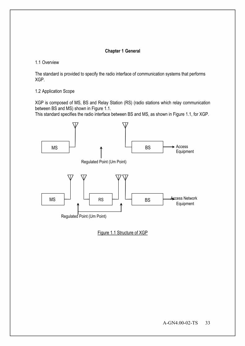
A-GN4.00-02-TS 33
Chapter 1 General
1.1 Overview The standard is provided to specify the radio interface of communication systems that performs XGP. 1.2 Application Scope XGP is composed of MS, BS and Relay Station (RS) (radio stations which relay communication between BS and MS) shown in Figure 1.1. This standard specifies the radio interface between BS and MS, as shown in Figure 1.1, for XGP.
Figure 1.1 Structure of XGP
Access Equipment
Regulated Point (Um Point)
Mobile statio Base
Mobile statio
Relay statio Equipment Base
MS BS
MS RS BS
Regulated Point (Um Point)
Access Network

34 A-GN4.00-02-TS
1.3 Mandatory and Optional This standard includes both mandatory and optional descriptions. The items necessary for system interface are defined as mandatory, and the items that depend on the manufacture are defined as optional. 1.4 Public Mode and Private Mode Original PHS takes both service forms in public mode and in private mode. Because Original PHS concept is that it is utilized both in public system such as office extension line and in private system such as home circuit, XGP will have the same function of public mode and private mode. The standard of private mode will be defined in the future.

A-GN4.00-02-TS 35
Chapter 2 System Overview
2.1 System Structure XGP consists of MS, BS and relay station which relays communications between BS and MS (hereinafter, referred to as RS). 2.1.1 Mobile Station (MS) A mobile station, or a subscriber communication terminal, is used to make mobile radio communication to either mobile station or base station. A mobile station consists of radio equipment with antenna, transmitter and receiver; interface to external equipments, voice encoding equipment, control equipment, and a sending/receiving handset etc. In addition, the terminal, such as personal computer, can be connected to the MS if needed. 2.1.2 Base Station (BS) A base station carries out mobile radio communication with mobile stations. A base station consists of radio equipment with antenna, transmitter and receiver and control equipment. 2.1.3 Relay Station (RS) A relay station relays mobile radio communication between BS and MS. The detail specification of RS will be defined in the future. Counterpart of relay station to BS or MS consists of radio equipment with antenna, transmitter and receiver and control equipment.
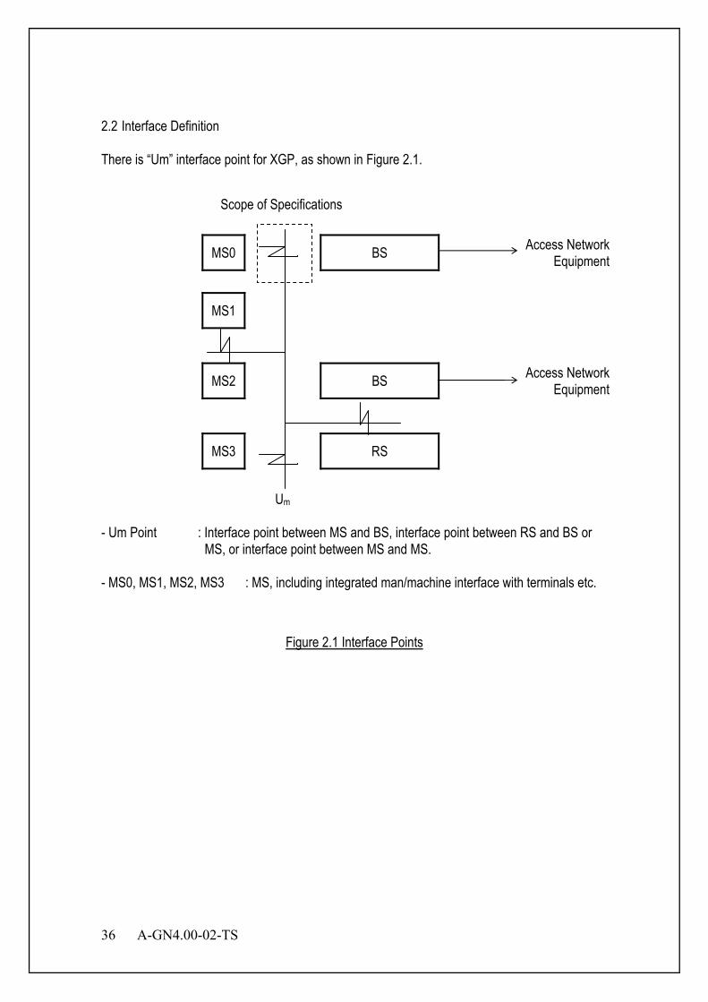
36 A-GN4.00-02-TS
2.2 Interface Definition There is “Um” interface point for XGP, as shown in Figure 2.1.
MS0 BS Access Network Equipment
MS1
MS2 BS Access Network Equipment
MS3 RS
Um
- Um Point : Interface point between MS and BS, interface point between RS and BS or
MS, or interface point between MS and MS. - MS0, MS1, MS2, MS3 : MS, including integrated man/machine interface with terminals etc.
Figure 2.1 Interface Points
Scope of Specifications
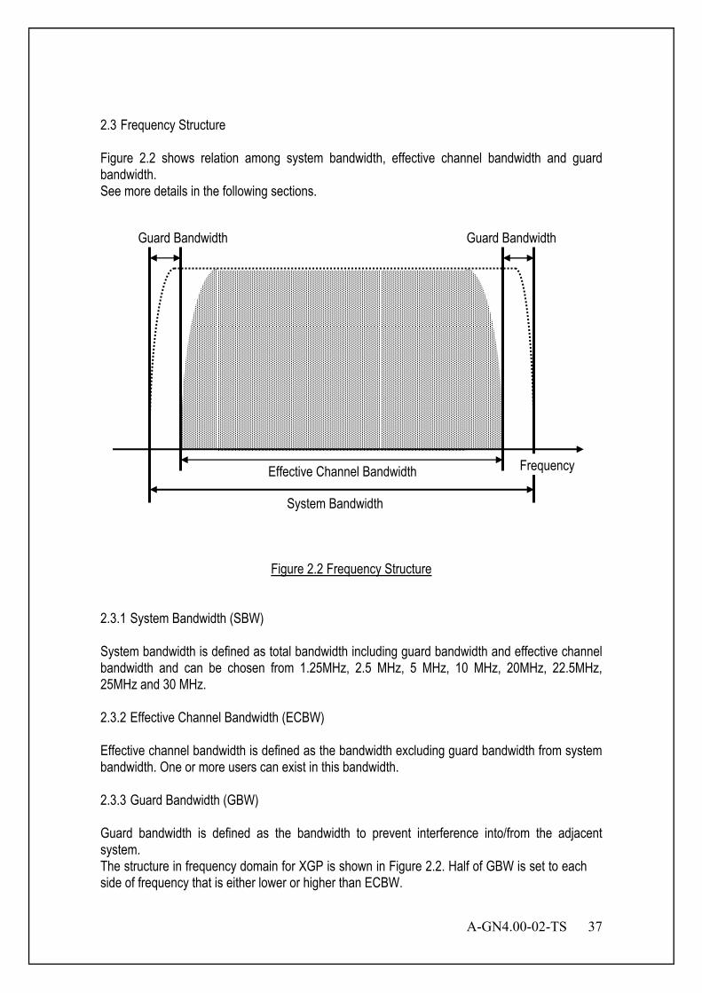
A-GN4.00-02-TS 37
2.3 Frequency Structure Figure 2.2 shows relation among system bandwidth, effective channel bandwidth and guard bandwidth. See more details in the following sections.
Figure 2.2 Frequency Structure
2.3.1 System Bandwidth (SBW) System bandwidth is defined as total bandwidth including guard bandwidth and effective channel bandwidth and can be chosen from 1.25MHz, 2.5 MHz, 5 MHz, 10 MHz, 20MHz, 22.5MHz, 25MHz and 30 MHz. 2.3.2 Effective Channel Bandwidth (ECBW) Effective channel bandwidth is defined as the bandwidth excluding guard bandwidth from system bandwidth. One or more users can exist in this bandwidth. 2.3.3 Guard Bandwidth (GBW) Guard bandwidth is defined as the bandwidth to prevent interference into/from the adjacent system. The structure in frequency domain for XGP is shown in Figure 2.2. Half of GBW is set to each side of frequency that is either lower or higher than ECBW.
Guard Bandwidth Guard Bandwidth
Effective Channel Bandwidth
System Bandwidth
Frequency
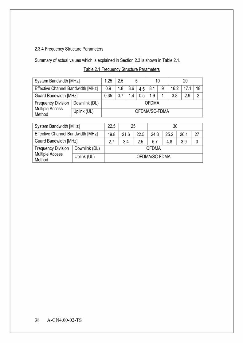
38 A-GN4.00-02-TS
2.3.4 Frequency Structure Parameters Summary of actual values which is explained in Section 2.3 is shown in Table 2.1.
Table 2.1 Frequency Structure Parameters
System Bandwidth [MHz] 1.25 2.5 5 10 20 Effective Channel Bandwidth [MHz] 0.9 1.8 3.6 4.5 8.1 9 16.2 17.1 18 Guard Bandwidth [MHz] 0.35 0.7 1.4 0.5 1.9 1 3.8 2.9 2 Frequency Division Multiple Access Method
Downlink (DL) OFDMA Uplink (UL) OFDMA/SC-FDMA
System Bandwidth [MHz] 22.5 25 30 Effective Channel Bandwidth [MHz] 19.8 21.6 22.5 24.3 25.2 26.1 27 Guard Bandwidth [MHz] 2.7 3.4 2.5 5.7 4.8 3.9 3 Frequency Division Multiple Access Method
Downlink (DL) OFDMA Uplink (UL) OFDMA/SC-FDMA

A-GN4.00-02-TS 39
2.4 Access Method The access method of DL for XGP is OFDMA/TDMA-TDD. The access method of UL for XGP is OFDMA/TDMA-TDD or SC-FDMA/TDMA-TDD. TDD frame period is 2.5ms, 5 ms and 10ms. The ratio between transmission and the reception slots are variable and their combination are repeated. Each slot time is 625 us and TDMA access, and is operated by single carrier for Original PHS. XGP has the same frame format as Original PHS, and adopts the OFDMA for frequency division multiple access.
Figure 2.3 OFDMA/SC-FDMA/TDMA-TDD (XGP) in case of 5ms frame and UL/DL equal ratio
2.4.1 Transmission Method The basic configurations for XGP are shown in Table 2.2.
Table 2.2 Basic Configuration of XGP
Basic Configuration Contents Duplex Method TDD DL Access Method OFDMA/TDMA UL Access Method OFDMA, SC-FDMA/TDMA TDMA Frame Period 2.5, 5, 10 ms Sub-carrier Spacing 10.94kHz,12.5 kHz,15 kHz, 37.5 kHz
TDMA-TDD (Original PHS)
Frequency
UL
5 ms/frame
Time
1 frame
Frequency
DL UL
DL
Time
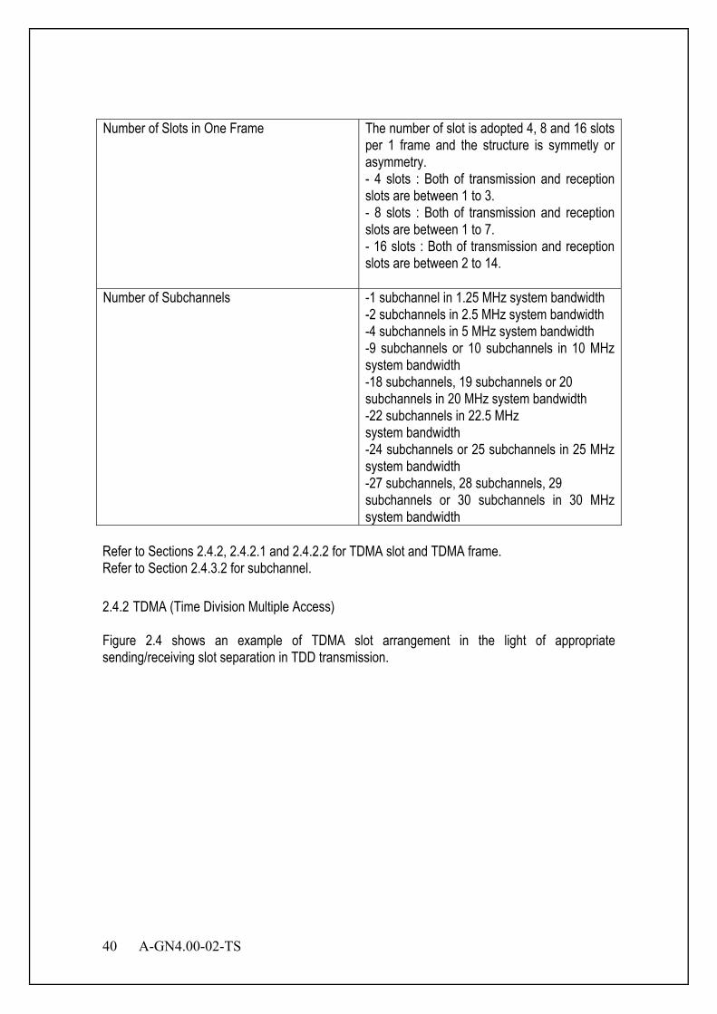
40 A-GN4.00-02-TS
Number of Slots in One Frame The number of slot is adopted 4, 8 and 16 slots per 1 frame and the structure is symmetly or asymmetry. - 4 slots : Both of transmission and reception slots are between 1 to 3. - 8 slots : Both of transmission and reception slots are between 1 to 7. - 16 slots : Both of transmission and reception slots are between 2 to 14.
Number of Subchannels -1 subchannel in 1.25 MHz system bandwidth -2 subchannels in 2.5 MHz system bandwidth -4 subchannels in 5 MHz system bandwidth -9 subchannels or 10 subchannels in 10 MHz system bandwidth -18 subchannels, 19 subchannels or 20 subchannels in 20 MHz system bandwidth -22 subchannels in 22.5 MHz system bandwidth -24 subchannels or 25 subchannels in 25 MHz system bandwidth -27 subchannels, 28 subchannels, 29 subchannels or 30 subchannels in 30 MHz system bandwidth
Refer to Sections 2.4.2, 2.4.2.1 and 2.4.2.2 for TDMA slot and TDMA frame. Refer to Section 2.4.3.2 for subchannel. 2.4.2 TDMA (Time Division Multiple Access) Figure 2.4 shows an example of TDMA slot arrangement in the light of appropriate sending/receiving slot separation in TDD transmission.

A-GN4.00-02-TS 41
V
V V V V V V
V V V V V V D4
V V VMS→BS
MS(1)→BS
MS(2)→BS
5 ms
2.5 ms 2.5 ms
625 us
U2 U4 D2 D4
U2 D2
U4
U: UL, D : DL, V : Vacant Ui - Di : Corresponding UL / DL slot
Figure 2.4 TDMA Slot Arrangement in case of 5ms symmetrical frame
2.4.2.1 TDMA Slot A slot is a minimum unit that composes TDMA, and its period is 625 us. This period is the same as Original PHS. 2.4.2.2 TDMA Frame A frame is composed one of 4, 8 or 16 slots. A frame structure is symmetly or asymmetry depended on the ration between UL and DL. The structure should be calculated as follows.
16or 8 4, = + :slot ofnumber Total14 1 :""slot DL14 1 :""slot UL
) + ( 625us = frame 1
DSLUSL
DSLDSL
USLUSL
DSLUSL
NNNNNN
N N
≤≤≤≤
×
Transmission burst lengths for UL and DL are below. UL:625us×NUSL or under (1≤NUSL≤14) DL:625us×NDSL or under (1≤NDSL≤14)
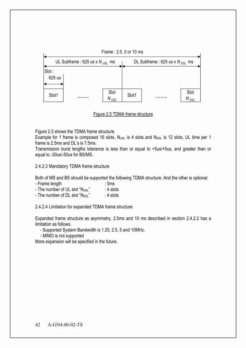
42 A-GN4.00-02-TS
Slot1 ....... SlotN USL
Slot1 SlotN DSL
625 usSlot :
UL Subframe : 625 us x N USL ms
Frame : 2.5, 5 or 10 ms
DL Subframe : 625 us x N DSL ms
.......
Figure 2.5 TDMA frame structure
Figure 2.5 shows the TDMA frame structure. Example for 1 frame is composed 16 slots, NUSL is 4 slots and NDSL is 12 slots, UL time per 1 frame is 2.5ms and DL’s is 7.5ms. Transmission burst lengths tolerance is less than or equal to +5us/+5us, and greater than or equal to -30us/-50us for BS/MS. 2.4.2.3 Mandatory TDMA frame structure Both of MS and BS should be supported the following TDMA structure. And the other is optional - Frame length : 5ms - The number of UL slot “NUSL” : 4 slots - The number of DL slot “NDSL” : 4 slots 2.4.2.4 Limitation for expanded TDMA frame structure Expanded frame structure as asymmetry, 2.5ms and 10 ms described in section 2.4.2.2 has a limitation as follows.
- Supported System Bandwidth is 1.25, 2.5, 5 and 10MHz. - MIMO is not supported
More expansion will be specified in the future.

A-GN4.00-02-TS 43
2.4.3 OFDMA (Orthogonal Frequency Division Multiple Access) Figure 2.6 shows the OFDMA subchannel structure.
Subchannel
Subcarrier Spacing Guard Carrier DC CarrierSubcarrier
Subcarriernumber
12
34
56
78
910
1112
1314
1516
1718
1920
2122
2324
Frequency
Frequency
Figure 2.6 OFDMA Structure
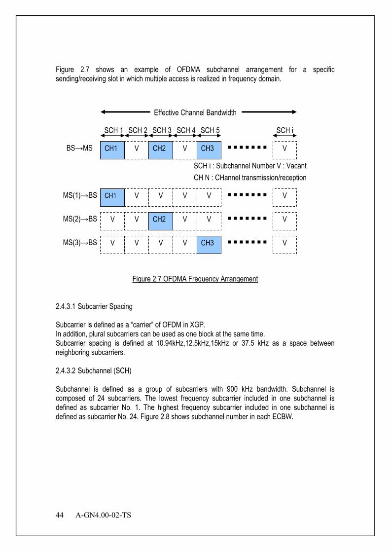
44 A-GN4.00-02-TS
Figure 2.7 shows an example of OFDMA subchannel arrangement for a specific sending/receiving slot in which multiple access is realized in frequency domain.
Figure 2.7 OFDMA Frequency Arrangement
2.4.3.1 Subcarrier Spacing Subcarrier is defined as a “carrier” of OFDM in XGP. In addition, plural subcarriers can be used as one block at the same time. Subcarrier spacing is defined at 10.94kHz,12.5kHz,15kHz or 37.5 kHz as a space between neighboring subcarriers. 2.4.3.2 Subchannel (SCH) Subchannel is defined as a group of subcarriers with 900 kHz bandwidth. Subchannel is composed of 24 subcarriers. The lowest frequency subcarrier included in one subchannel is defined as subcarrier No. 1. The highest frequency subcarrier included in one subchannel is defined as subcarrier No. 24. Figure 2.8 shows subchannel number in each ECBW.
Effective Channel Bandwidth
SCH 1 SCH 2 SCH 3 SCH 4 SCH 5 SCH i
V V V CH1 CH2 CH3 BS→MS
SCH i : Subchannel Number V : Vacant CH N : CHannel transmission/reception
V V V CH1 MS(1)→BS
V V V CH2
V V
V V
V V
MS(2)→BS
MS(3)→BS V V CH3 V
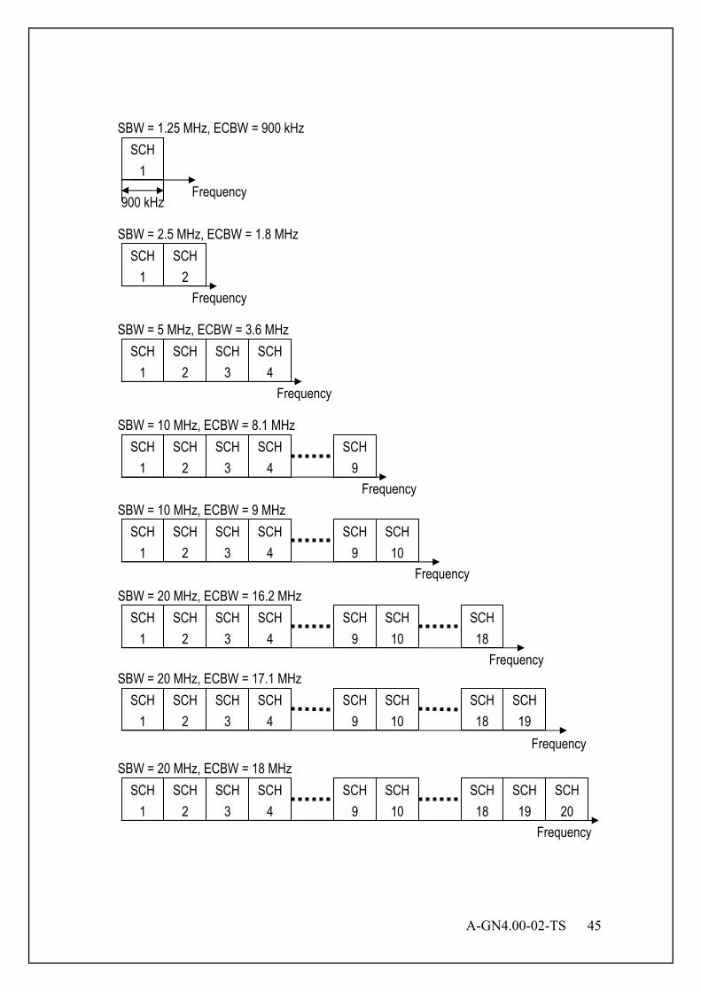
A-GN4.00-02-TS 45
SCH 1
Frequency
SBW = 1.25 MHz, ECBW = 900 kHz
900 kHz
SCH 1
SCH 2
SCH 1
SCH 2
SCH 3
SCH 4
SCH 1
SCH 2
SCH 3
SCH 4
SCH 9
SCH 1
SCH 2
SCH 3
SCH 4
SCH 9
SCH 10
SCH 1
SCH 2
SCH 3
SCH 4
SCH 9
SCH 10
SCH 1
SCH 2
SCH 3
SCH 4
SCH 9
SCH 10
SCH 1
SCH 2
SCH 3
SCH 4
SCH 9
SCH 10
SCH 18
SCH 19
SCH 18
SCH 19
SCH 20
SCH 18
Frequency
Frequency
Frequency
Frequency
Frequency
Frequency
Frequency
SBW = 2.5 MHz, ECBW = 1.8 MHz
SBW = 5 MHz, ECBW = 3.6 MHz
SBW = 10 MHz, ECBW = 8.1 MHz
SBW = 10 MHz, ECBW = 9 MHz
SBW = 20 MHz, ECBW = 16.2 MHz
SBW = 20 MHz, ECBW = 17.1 MHz
SBW = 20 MHz, ECBW = 18 MHz
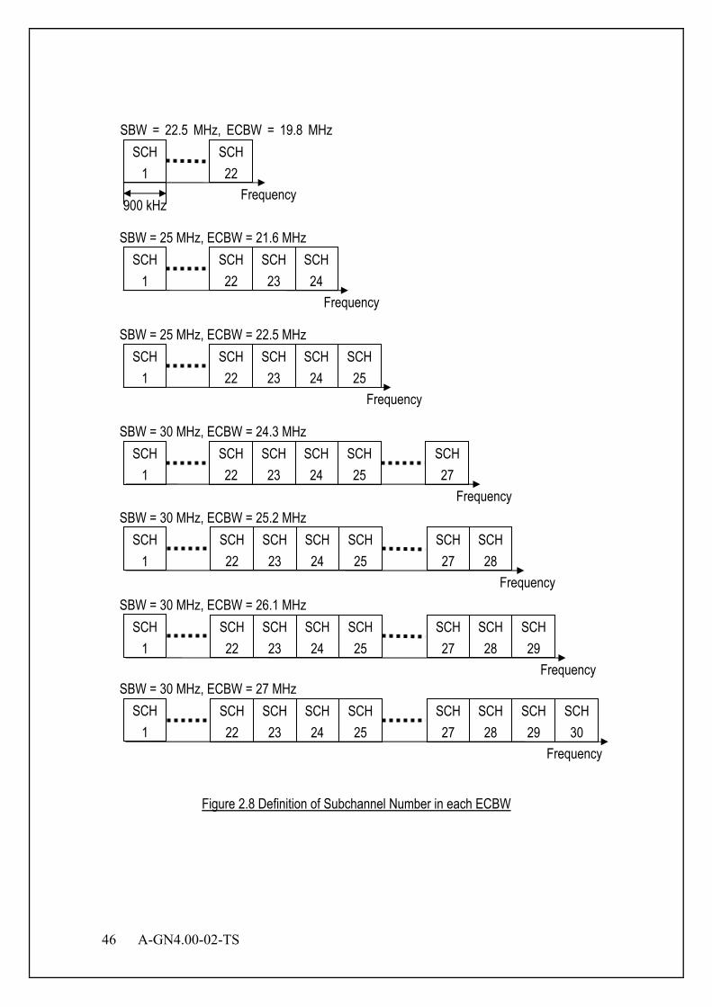
46 A-GN4.00-02-TS
Figure 2.8 Definition of Subchannel Number in each ECBW
SCH 1
SBW = 22.5 MHz, ECBW = 19.8 MHz
900 kHz
SCH 1
SCH 1
SCH 1
SCH 1
SCH 1
SCH 1
SBW = 25 MHz, ECBW = 21.6 MHz
SBW = 25 MHz, ECBW = 22.5 MHz
SBW = 30 MHz, ECBW = 24.3 MHz
SBW = 30 MHz, ECBW = 25.2 MHz
SBW = 30 MHz, ECBW = 26.1 MHz
SBW = 30 MHz, ECBW = 27 MHz
SCH 1
Frequency
SCH 22
SCH 24
Frequency
SCH 22
SCH 23
SCH 24
SCH 25
SCH 22
SCH 23
SCH 24
SCH 25
SCH 22
SCH 23
SCH 27
Frequency
SCH 24
SCH 25
SCH 28
SCH 22
SCH 23
SCH 27
SCH 24
SCH 25
SCH 28
SCH 29
SCH 22
SCH 23
SCH 27
SCH 24
SCH 25
SCH 28
SCH 29
SCH 30
SCH 22
SCH 23
SCH 27
Frequency
Frequency
Frequency
Frequency
A-GN4.00-02-TS 47
2.4.3.3 DC Carrier DC carrier is not used for data transmission. When one subchannel is in use, DC carrier is set at subcarrier No. 13 as shown in Figure 2.6. The way to set DC carrier for the improvement of data throughput is described in Section 2.7. 2.4.3.4 Guard Carrier To avoid the interference between subcarriers used by different MS, the guard carrier is not used for data transmission. Guard carrier insertion depends on the DL/UL subchannel format. When one subchannel is in use, guard carrier is set at subcarrier No. 1 as shown in Figure 2.6. The way to set guard carrier for the improvement of data throughput is described in Section 2.7. 2.4.4 OFDMA and TDMA This XGP allows both frequency division multiple access and time division multiple access. Figure 2.9 shows the example of the combination of OFDMA/TDMA access. The detail of channel assignment is defined in 0.

48 A-GN4.00-02-TS
Figure 2.9 OFDMA/TDMA Slot Arrangement
2.4.5 Single Carrier Frequency Division Multiple Access (SC-FDMA) Mode Coexistence with OFDMA UL XGP has SC-FDMA mode in UL, and allows the coexistence of SC-FDMA and OFDMA. Figure 2.10 shows the example of the combination of OFDMA and SC-FDMA UL access.
V V V U1 V V V
Frequency
V V V V U2 V V V V
V V V V D2 V V V V
D1
Time
BS→MS U : UL D : DL V : Vacant Ui – Di : Corresponding UL/DL Slot
SCH1 SCH2 SCH3
SCH i
V V V U1 V V V
V V V V V V V V
V V V V V V V V
D1
V V V V
V V V V
SCH1 SCH2 SCH3
SCH i
SCH1 SCH2 SCH3
SCH i V V V V V V
V V V V U2 V V V V
V V V V D2 V V V V
V V
MS(1)→BS
MS(2)→BS

A-GN4.00-02-TS 49
Figure 2.10 OFDMA and SC-FDMA Slot Arrangement
D2 V V U1 U2 V V
Frequency
V V V V U3 V V V V
V V V V D3 V V VI VI
Time
BS→MS(OFDMA and SC-FDMA UL) U : UL D : DL V : Vacant Ui – Di : Corresponding UL/DL Slot
SCH1 SCH2 SCH3
SCH i
V V V U1 V V V
V V V V V V V V
V V V V V V V V
D1
V V V V
V V V V
SCH1 SCH2 SCH3
SCH i
SCH1 SCH2 SCH3
SCH i D2 V V U2 V V
V V V V V V V V
V V V V V V V V
V V
MS(1)(OFDMA)→BS
MS(2)(SC-FDMA)→BS
D1
SCH1 SCH2 SCH3
SCH i V V V V V V
V V V V U3 V V V V
V V V V D3 V V V V
V V
MS(2)(OFDMA)→BS
V V V V
V V V V
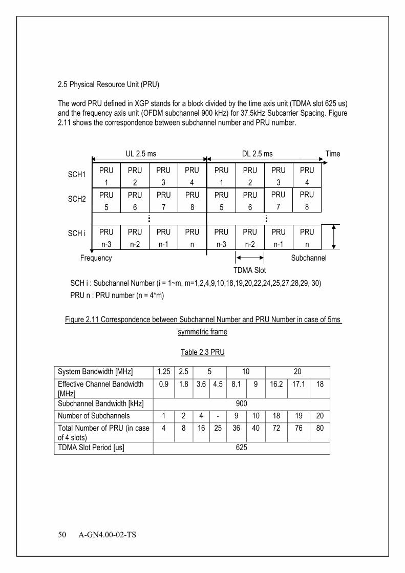
50 A-GN4.00-02-TS
2.5 Physical Resource Unit (PRU) The word PRU defined in XGP stands for a block divided by the time axis unit (TDMA slot 625 us) and the frequency axis unit (OFDM subchannel 900 kHz) for 37.5kHz Subcarrier Spacing. Figure 2.11 shows the correspondence between subchannel number and PRU number.
Figure 2.11 Correspondence between Subchannel Number and PRU Number in case of 5ms symmetric frame
Table 2.3 PRU
System Bandwidth [MHz] 1.25 2.5 5 10 20 Effective Channel Bandwidth [MHz]
0.9 1.8 3.6 4.5 8.1 9 16.2 17.1 18
Subchannel Bandwidth [kHz] 900 Number of Subchannels 1 2 4 - 9 10 18 19 20 Total Number of PRU (in case of 4 slots)
4 8 16 25 36 40 72 76 80
TDMA Slot Period [us] 625
PRU 2
PRU 3
PRU 4
PRU 5
PRU 6
PRU n-3
PRU n-2
PRU n-1
PRU n
PRU 1
Frequency
Time UL 2.5 ms DL 2.5 ms
TDMA Slot Subchannel
SCH1
SCH2
SCH i
PRU 2
PRU 3
PRU 4
PRU 5
PRU 6
PRU 1
PRU n-3
PRU n-2
PRU n-1
PRU n
SCH i : Subchannel Number (i = 1~m, m=1,2,4,9,10,18,19,20,22,24,25,27,28,29, 30) PRU n : PRU number (n = 4*m)
PRU 7
PRU 8
PRU 7
PRU 8
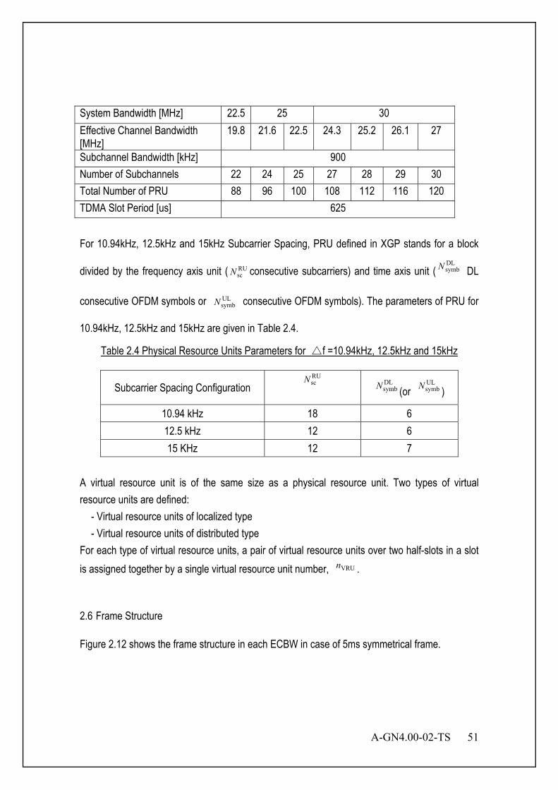
A-GN4.00-02-TS 51
System Bandwidth [MHz] 22.5 25 30 Effective Channel Bandwidth [MHz]
19.8 21.6 22.5 24.3 25.2 26.1 27
Subchannel Bandwidth [kHz] 900 Number of Subchannels 22 24 25 27 28 29 30 Total Number of PRU 88 96 100 108 112 116 120 TDMA Slot Period [us] 625
For 10.94kHz, 12.5kHz and 15kHz Subcarrier Spacing, PRU defined in XGP stands for a block
divided by the frequency axis unit ( RUscN consecutive subcarriers) and time axis unit (
DLsymbN DL
consecutive OFDM symbols or ULsymbN consecutive OFDM symbols). The parameters of PRU for
10.94kHz, 12.5kHz and 15kHz are given in Table 2.4.
Table 2.4 Physical Resource Units Parameters for △f =10.94kHz, 12.5kHz and 15kHz
Subcarrier Spacing Configuration RUscN DL
symbN (or ULsymbN )
10.94 kHz 18 6 12.5 kHz 12 6 15 KHz 12 7
A virtual resource unit is of the same size as a physical resource unit. Two types of virtual resource units are defined:
- Virtual resource units of localized type - Virtual resource units of distributed type
For each type of virtual resource units, a pair of virtual resource units over two half-slots in a slot is assigned together by a single virtual resource unit number, VRUn . 2.6 Frame Structure Figure 2.12 shows the frame structure in each ECBW in case of 5ms symmetrical frame.

52 A-GN4.00-02-TS
PRU 1 PRU 2 PRU 3 PRU 4 PRU 1 PRU 2 PRU 3 PRU 4
PRU 5 PRU 6 PRU 7 PRU 8 PRU 5 PRU 6 PRU 7 PRU 8
PRU 9 PRU 10 PRU 11 PRU 12 PRU 9 PRU 10 PRU 11 PRU 12
PRU 13 PRU 14 PRU 15 PRU 16 PRU 13 PRU 14 PRU 15 PRU 16
PRU 33 PRU 34 PRU 35 PRU 36 PRU 33 PRU 34 PRU 35 PRU 36
PRU 37 PRU 38 PRU 39 PRU 40 PRU 37 PRU 38 PRU 39 PRU 40
PRU 69 PRU 70 PRU 71 PRU 72 PRU 69 PRU 70 PRU 71 PRU 72
PRU 73 PRU 74 PRU 75 PRU 76 PRU 73 PRU 74 PRU 75 PRU 76
PRU 77 PRU 78 PRU 79 PRU 80 PRU 77 PRU 78 PRU 79 PRU 80
PRU 85 PRU 86 PRU 87 PRU 88 PRU 85 PRU 86 PRU 87 PRU 88
PRU 93 PRU 94 PRU 95 PRU 96 PRU 93 PRU 94 PRU 95 PRU 96
PRU 97 PRU 98 PRU 99 PRU 100 PRU 97 PRU 98 PRU 99 PRU 100
PRU 105 PRU 106 PRU 107 PRU 108 PRU 105 PRU 106 PRU 107 PRU 108
PRU 109 PRU 110 PRU 111 PRU 112 PRU 109 PRU 110 PRU 111 PRU 112
PRU 113 PRU 114 PRU 115 PRU 116 PRU 113 PRU 114 PRU 115 PRU 116
PRU 117 PRU 118 PRU 119 PRU 120 PRU 117 PRU 118 PRU 119 PRU 120
UL DL
Frequency UL PRU DL PRU
21.6M
Hz90
0kHz
1.8MH
z3.6
8.1
9 MHz
16.2
MHz
18 M
Hz17.1
MHz
22.5
MHz
24.3
MHz
25.2
MHz
26.1
MHz
27 M
Hz
19.8M
Hz
Figure 2.12 Frame Structure in case of 5ms symmetrical frame
Figure 2.13. shows the frame structure in case of 10ms frame. Each frame consists of two 5ms half-frames. Each half-frame consists of five slots of length 1ms. Each slot is defined as two half-slots of length 0.5ms. Downlink slot is reserved for downlink transmissions, uplink slot is reserved for uplink transmissions. The special slot exists in both half-frames. Slot 1 and Slot 6 are reserved for special slot with the three fields DSS, AGT and USS. Two special slot configuration can be used according to different
deployment scenario. For the first slot configuration, the length of DSS is ms480103 and the length
of USS is ms960137 . For the second slot configuration, the length of DSS is ms
480343 and the
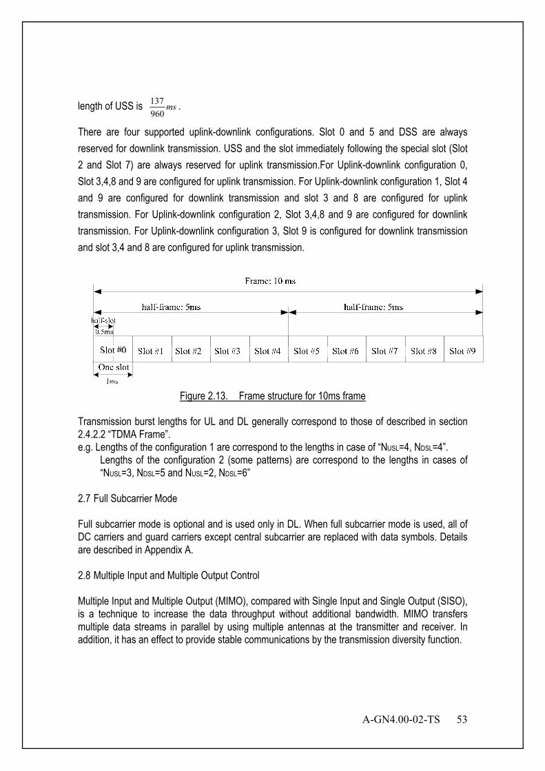
A-GN4.00-02-TS 53
length of USS is ms960137 .
There are four supported uplink-downlink configurations. Slot 0 and 5 and DSS are always reserved for downlink transmission. USS and the slot immediately following the special slot (Slot 2 and Slot 7) are always reserved for uplink transmission.For Uplink-downlink configuration 0, Slot 3,4,8 and 9 are configured for uplink transmission. For Uplink-downlink configuration 1, Slot 4 and 9 are configured for downlink transmission and slot 3 and 8 are configured for uplink transmission. For Uplink-downlink configuration 2, Slot 3,4,8 and 9 are configured for downlink transmission. For Uplink-downlink configuration 3, Slot 9 is configured for downlink transmission and slot 3,4 and 8 are configured for uplink transmission.
Figure 2.13. Frame structure for 10ms frame
Transmission burst lengths for UL and DL generally correspond to those of described in section 2.4.2.2 “TDMA Frame”. e.g. Lengths of the configuration 1 are correspond to the lengths in case of “NUSL=4, NDSL=4”.
Lengths of the configuration 2 (some patterns) are correspond to the lengths in cases of “NUSL=3, NDSL=5 and NUSL=2, NDSL=6”
2.7 Full Subcarrier Mode Full subcarrier mode is optional and is used only in DL. When full subcarrier mode is used, all of DC carriers and guard carriers except central subcarrier are replaced with data symbols. Details are described in Appendix A. 2.8 Multiple Input and Multiple Output Control Multiple Input and Multiple Output (MIMO), compared with Single Input and Single Output (SISO), is a technique to increase the data throughput without additional bandwidth. MIMO transfers multiple data streams in parallel by using multiple antennas at the transmitter and receiver. In addition, it has an effect to provide stable communications by the transmission diversity function.

54 A-GN4.00-02-TS
2.9 Protocol Model Protocol model is composed of link establishment phase, access establishment phase and access phase. 2.9.1 Link Establishment Phase Link establishment phase is defined as the stage to use common channel (CCH) functions to select the protocol type required in the next phase. 2.9.2 Access Establishment Phase Access establishment phase is defined as the stage to use functions which is obtained in the link establishment phase to select the protocol type required in the next phase. 2.9.3 Access Phase In the access phase, it is possible to employ the optimum channel and the optimum protocol for each service. 2.9.4 Optional Protocol Model 2.9.4.1 User plane Figure 2.14 shows the protocol stack for the user-plane, where MSL 1, MSL 2 and MSL 3 sublayers (terminated in BS on the network side) perform the functions listed for the user plane, e.g. header compression, ciphering, scheduling, ARQ and HARQ;
BS
PHY
MS
PHY
MSL 1
MSL 2
MSL 1
MSL 3MSL 3
MSL 2
Figure 2.14 User-plane protocol stack
2.9.4.2 Control plane The figure below shows the protocol stack for the control-plane, where:
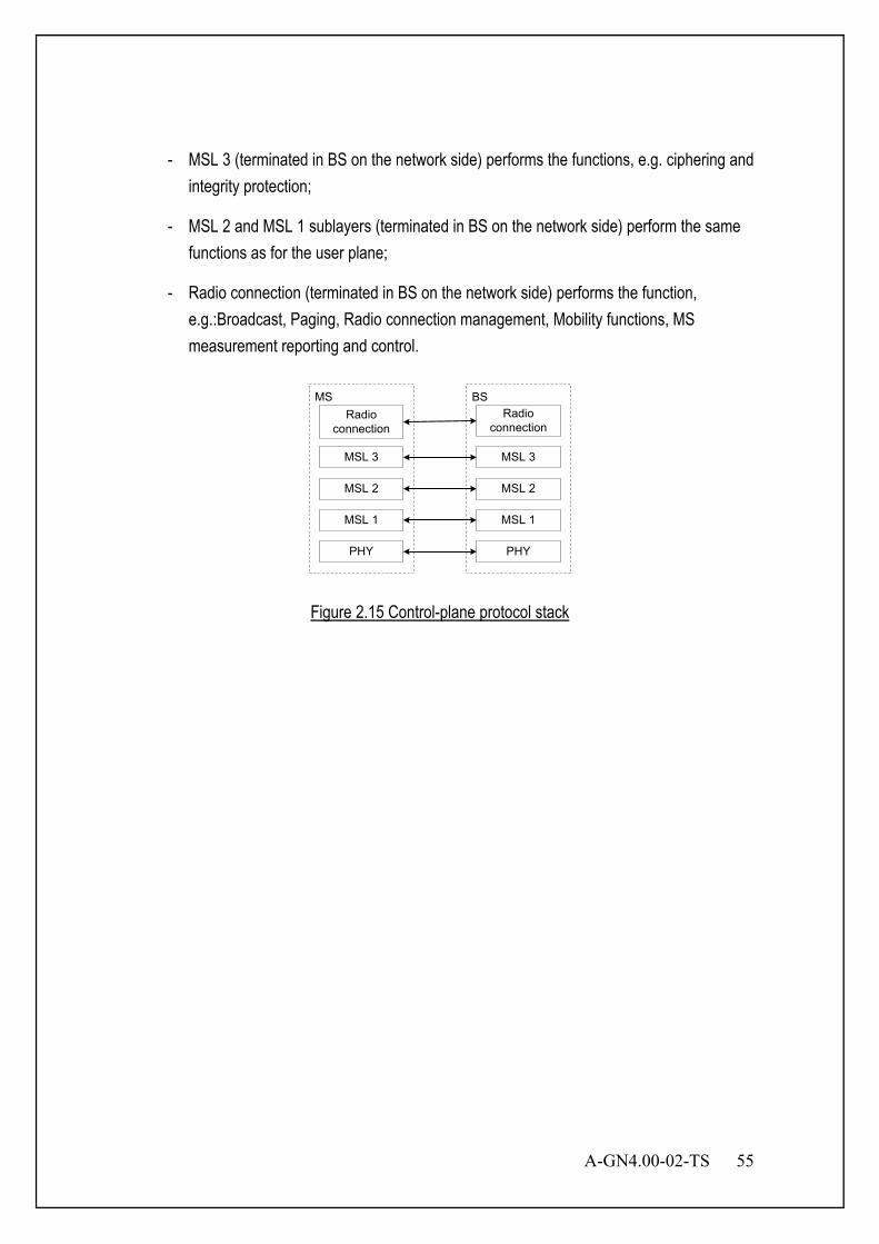
A-GN4.00-02-TS 55
- MSL 3 (terminated in BS on the network side) performs the functions, e.g. ciphering and integrity protection;
- MSL 2 and MSL 1 sublayers (terminated in BS on the network side) perform the same functions as for the user plane;
- Radio connection (terminated in BS on the network side) performs the function, e.g.:Broadcast, Paging, Radio connection management, Mobility functions, MS measurement reporting and control.
BS
PHY
MS
PHY
MSL 1
MSL 2
MSL 1
MSL 2
Radio connection
Radio connection
MSL 3 MSL 3
Figure 2.15 Control-plane protocol stack
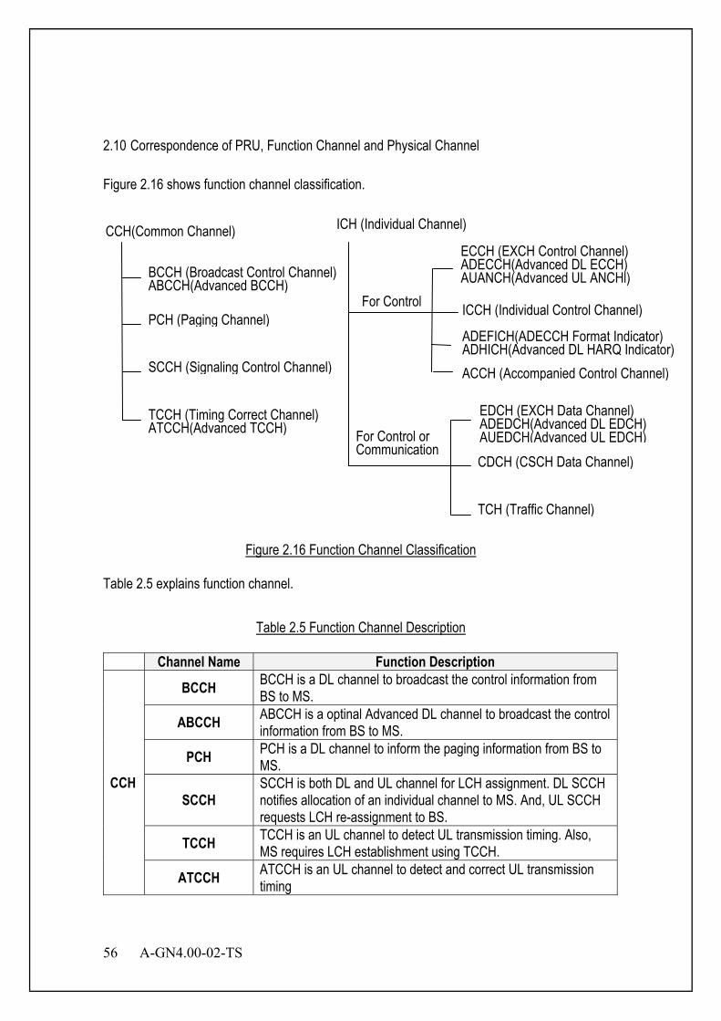
56 A-GN4.00-02-TS
CCH(Common Channel)
2.10 Correspondence of PRU, Function Channel and Physical Channel Figure 2.16 shows function channel classification.
Figure 2.16 Function Channel Classification
Table 2.5 explains function channel.
Table 2.5 Function Channel Description
Channel Name Function Description
CCH
BCCH BCCH is a DL channel to broadcast the control information from BS to MS.
ABCCH ABCCH is a optinal Advanced DL channel to broadcast the control information from BS to MS.
PCH PCH is a DL channel to inform the paging information from BS to MS.
SCCH SCCH is both DL and UL channel for LCH assignment. DL SCCH notifies allocation of an individual channel to MS. And, UL SCCH requests LCH re-assignment to BS.
TCCH TCCH is an UL channel to detect UL transmission timing. Also, MS requires LCH establishment using TCCH.
ATCCH ATCCH is an UL channel to detect and correct UL transmission timing
BCCH (Broadcast Control Channel) ABCCH(Advanced BCCH)
PCH (Paging Channel)
SCCH (Signaling Control Channel)
TCCH (Timing Correct Channel) ATCCH(Advanced TCCH)
ICH (Individual Channel)
ECCH (EXCH Control Channel) ADECCH(Advanced DL ECCH) AUANCH(Advanced UL ANCHl) ICCH (Individual Control Channel)
ACCH (Accompanied Control Channel)
EDCH (EXCH Data Channel) ADEDCH(Advanced DL EDCH) AUEDCH(Advanced UL EDCH) CDCH (CSCH Data Channel)
TCH (Traffic Channel)
For Control
For Control or Communication
ADEFICH(ADECCH Format Indicator) ADHICH(Advanced DL HARQ Indicator)
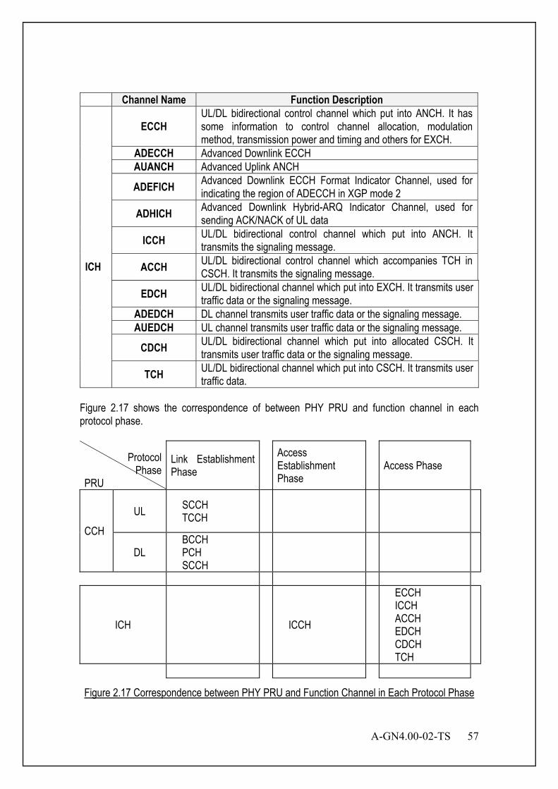
A-GN4.00-02-TS 57
Channel Name Function Description
ICH
ECCH UL/DL bidirectional control channel which put into ANCH. It has some information to control channel allocation, modulation method, transmission power and timing and others for EXCH.
ADECCH Advanced Downlink ECCH AUANCH Advanced Uplink ANCH
ADEFICH Advanced Downlink ECCH Format Indicator Channel, used for indicating the region of ADECCH in XGP mode 2
ADHICH Advanced Downlink Hybrid-ARQ Indicator Channel, used for sending ACK/NACK of UL data
ICCH UL/DL bidirectional control channel which put into ANCH. It transmits the signaling message.
ACCH UL/DL bidirectional control channel which accompanies TCH in CSCH. It transmits the signaling message.
EDCH UL/DL bidirectional channel which put into EXCH. It transmits user traffic data or the signaling message.
ADEDCH DL channel transmits user traffic data or the signaling message. AUEDCH UL channel transmits user traffic data or the signaling message.
CDCH UL/DL bidirectional channel which put into allocated CSCH. It transmits user traffic data or the signaling message.
TCH UL/DL bidirectional channel which put into CSCH. It transmits user traffic data.
Figure 2.17 shows the correspondence of between PHY PRU and function channel in each protocol phase.
Protocol Phase
PRU
Link Establishment Phase
Access Establishment Phase
Access Phase
CCH
UL SCCH TCCH
DL BCCH PCH SCCH
ICH ICCH
ECCH ICCH ACCH EDCH CDCH TCH
Figure 2.17 Correspondence between PHY PRU and Function Channel in Each Protocol Phase
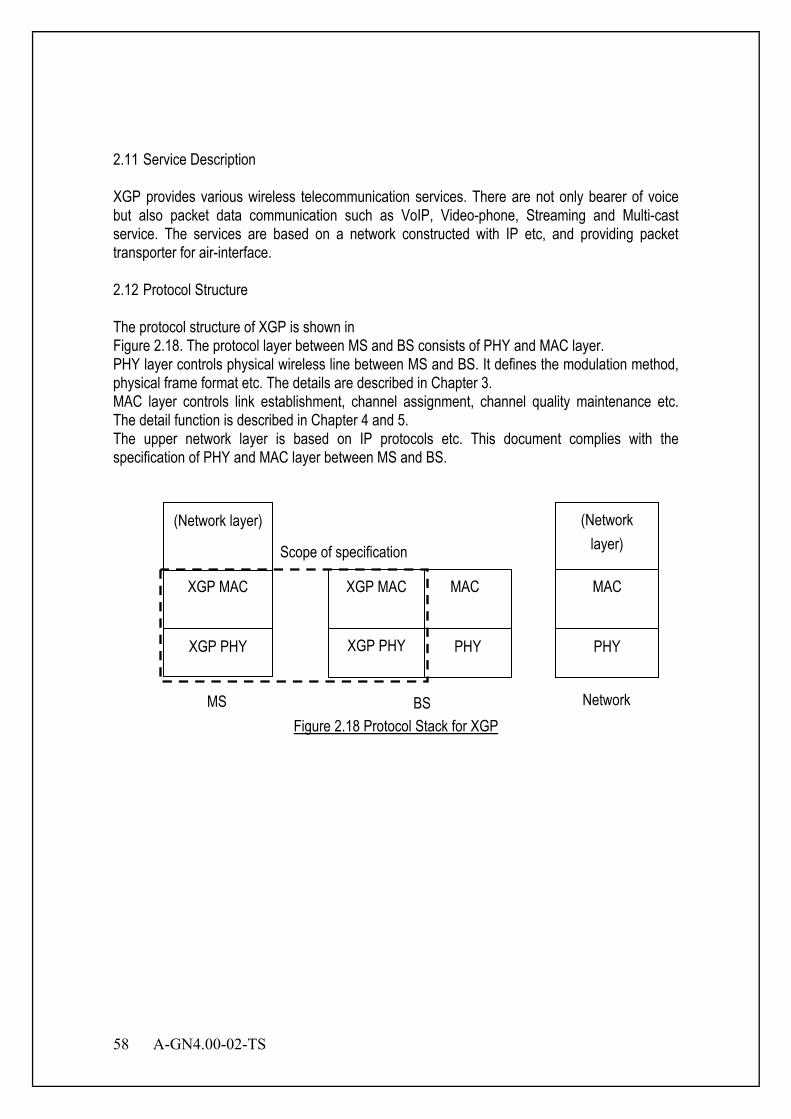
58 A-GN4.00-02-TS
2.11 Service Description XGP provides various wireless telecommunication services. There are not only bearer of voice but also packet data communication such as VoIP, Video-phone, Streaming and Multi-cast service. The services are based on a network constructed with IP etc, and providing packet transporter for air-interface. 2.12 Protocol Structure The protocol structure of XGP is shown in Figure 2.18. The protocol layer between MS and BS consists of PHY and MAC layer. PHY layer controls physical wireless line between MS and BS. It defines the modulation method, physical frame format etc. The details are described in Chapter 3. MAC layer controls link establishment, channel assignment, channel quality maintenance etc. The detail function is described in Chapter 4 and 5. The upper network layer is based on IP protocols etc. This document complies with the specification of PHY and MAC layer between MS and BS.
Figure 2.18 Protocol Stack for XGP
XGP PHY
XGP MAC
XGP PHY
XGP MAC
PHY PHY
MAC
(Network layer)
(Network layer)
MAC
MS BS Network
Scope of specification

A-GN4.00-02-TS 59
Chapter 3 Physical Channel Specification
3.1 Overview This chapter describes the technical requirements applied to radio transmission facilities for XGP. The following physical (PHY) layer specification is designed to satisfy the functional requirements that have been defined for XGP. It incorporates many aspects of existing standards in order to ensure reliable operation in the targeted 1 GHz to 3 GHz frequency band. In addition, PHY layer was designed with a high degree of flexibility in order to provide operators in different regulatory domains with the ability to optimize system deployments with respect to cell planning, cost considerations, radio capabilities, offered services, and capacity requirements. The DL PHY layer described in this chapter is based on Time Division Multiple Access (TDMA) and Orthogonal Frequency Division Multiple Access (OFDMA) modulation. The general condition of OFDM PHY layer is described in Section 3.2. The details of the DL PHY layer are described in Section 3.4. The UL PHY layer described in this chapter is based on TDMA and OFDMA modulation or TDMA and Single-Carrier Frequency Division Multiple Access (SC-FDMA) modulation. UL PHY layer in compliance with this standard shall support at least either OFDMA or SC-FDMA. The general condition of SC PHY layer is described in Section 3.3. The detail of the UL OFDM PHY layer is described in Section 3.5. The details of the UL SC PHY layer are described in Section 3.6. Physical channel is composed of two channels - Common Channel (CCH) and Individual Channel (ICH). CCH is composed of two channels – Common Control Channel (CCCH) and Timing Correct Channel (TCCH). ICH is composed of three channels - Anchor Channel (ANCH), Extra Channel (EXCH) and Circuit Switching Channel (CSCH). CCCH format is described in Sections 3.4.8.1.1, 3.5.6.1.1 and 3.6.7.1.1. TCCH format is described in Sections 3.5.6.1.2 and 3.6.7.1.2. ANCH is described in Sections 3.4.8.1.2, 3.5.6.2.1 and 3.6.7.2.1. EXCH format is described in Sections 3.4.8.1.3, 3.5.6.2.2 and 3.6.7.2.2. CSCH format is described in Sections 3.4.8.1.4, 3.5.7.2.3 and 3.6.7.2.3. The detail of ICH is described in Chapter 4. The detail of CCH is described in Chapter 5. Additional optional DL Physical channels are composed of: ADEDCH, ABCCH, ADEFICH, ADECCH and ADHICH. Additional optional UL Physical channel are composed of: AUEDCH, AUANCH and ATCCH. Subcarrier spacing in frequency is dictated by the multipath characteristics of the channels in which XGP is designated to operate. As the channel propagation characteristics depend on the topography of the area and on the cell radius, the amount of carriers into which the channels are subdivided depends on the overall channel width and the carrier spacing. This PHY layer specification contains the programmability to deal with this range of applications. Generally, several MIMO types have been already established. The effect achieved by the MIMO technology includes array gain, space diversity, spatial multiplexing, and interference reduction. In this document, the MIMO functions up to four streams is defined. The MIMO function relates to
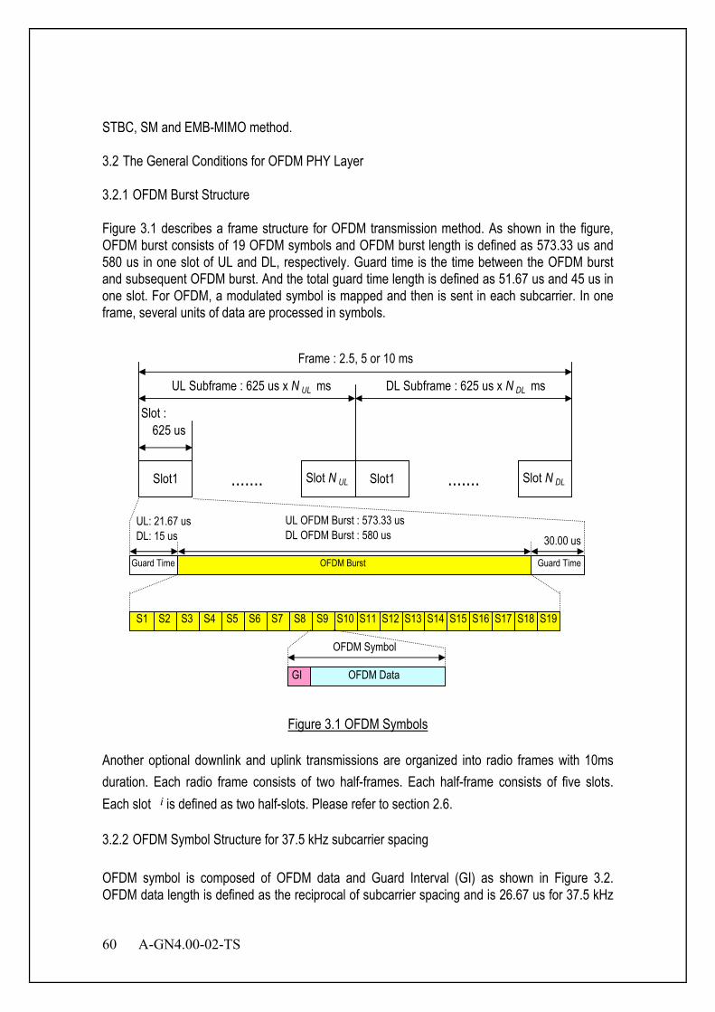
60 A-GN4.00-02-TS
STBC, SM and EMB-MIMO method. 3.2 The General Conditions for OFDM PHY Layer 3.2.1 OFDM Burst Structure Figure 3.1 describes a frame structure for OFDM transmission method. As shown in the figure, OFDM burst consists of 19 OFDM symbols and OFDM burst length is defined as 573.33 us and 580 us in one slot of UL and DL, respectively. Guard time is the time between the OFDM burst and subsequent OFDM burst. And the total guard time length is defined as 51.67 us and 45 us in one slot. For OFDM, a modulated symbol is mapped and then is sent in each subcarrier. In one frame, several units of data are processed in symbols.
Slot1 ....... Slot N UL Slot1 Slot N DL
625 usSlot :
UL Subframe : 625 us x N UL ms
Frame : 2.5, 5 or 10 ms
DL Subframe : 625 us x N DL ms
.......
S1 S2 S3 S4 S5 S6 S7 S8 S9 S10 S11 S12 S13 S14 S15 S16 S17 S18 S19
UL OFDM Burst : 573.33 usDL OFDM Burst : 580 us
GI OFDM Data
OFDM Symbol
Guard TimeGuard Time OFDM Burst
UL: 21.67 usDL: 15 us 30.00 us
Figure 3.1 OFDM Symbols
Another optional downlink and uplink transmissions are organized into radio frames with 10ms duration. Each radio frame consists of two half-frames. Each half-frame consists of five slots. Each slot i is defined as two half-slots. Please refer to section 2.6. 3.2.2 OFDM Symbol Structure for 37.5 kHz subcarrier spacing OFDM symbol is composed of OFDM data and Guard Interval (GI) as shown in Figure 3.2. OFDM data length is defined as the reciprocal of subcarrier spacing and is 26.67 us for 37.5 kHz
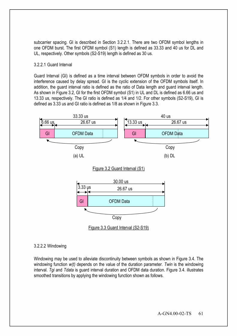
A-GN4.00-02-TS 61
subcarrier spacing. GI is described in Section 3.2.2.1. There are two OFDM symbol lengths in one OFDM burst. The first OFDM symbol (S1) length is defined as 33.33 and 40 us for DL and UL, respectively. Other symbols (S2-S19) length is defined as 30 us. 3.2.2.1 Guard Interval Guard Interval (GI) is defined as a time interval between OFDM symbols in order to avoid the interference caused by delay spread. GI is the cyclic extension of the OFDM symbols itself. In addition, the guard interval ratio is defined as the ratio of Data length and guard interval length. As shown in Figure 3.2, GI for the first OFDM symbol (S1) in UL and DL is defined as 6.66 us and 13.33 us, respectively. The GI ratio is defined as 1/4 and 1/2. For other symbols (S2-S19), GI is defined as 3.33 us and GI ratio is defined as 1/8 as shown in Figure 3.3.
Figure 3.2 Guard Interval (S1)
Figure 3.3 Guard Interval (S2-S19)
3.2.2.2 Windowing Windowing may be used to alleviate discontinuity between symbols as shown in Figure 3.4. The windowing function w(t) depends on the value of the duration parameter. Twin is the windowing interval. Tgi and Tdata is guard interval duration and OFDM data duration. Figure 3.4. illustrates smoothed transitions by applying the windowing function shown as follows.
GI OFDM Data
3.33 us 26.67 us
Copy
30.00 us
6.66 us 26.67 us 33.33 us
GI OFDM Data
Copy
(a) UL
13.33 us 26.67 us 40 us
OFDM Data
Copy
(b) DL
GI
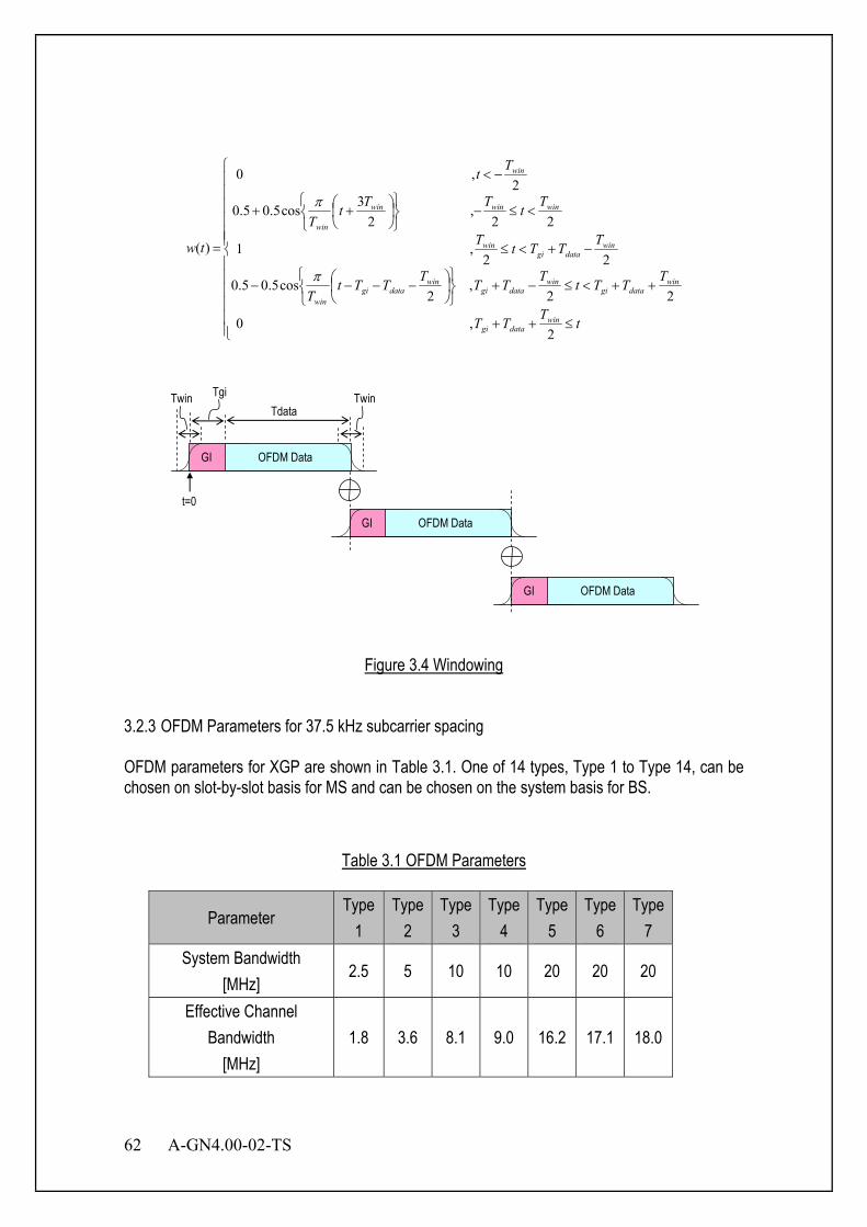
62 A-GN4.00-02-TS
≤++
++<≤−+
−−−−
−+<≤
<≤−
++
−<
=
tTTT
TTTtTTTTTTtT
TTTtT
TtTTtT
Tt
tw
windatagi
windatagi
windatagi
windatagi
win
windatagi
win
winwinwin
win
win
2,0
22,
2cos5.05.0
22,1
22,
23cos5.05.0
2,0
)(
π
π
Twin Tgi
Tdata
GI OFDM Data
GI OFDM Data
GI OFDM Data
Twin
t=0
Figure 3.4 Windowing
3.2.3 OFDM Parameters for 37.5 kHz subcarrier spacing OFDM parameters for XGP are shown in Table 3.1. One of 14 types, Type 1 to Type 14, can be chosen on slot-by-slot basis for MS and can be chosen on the system basis for BS.
Table 3.1 OFDM Parameters
Parameter Type
1 Type
2 Type
3 Type
4 Type
5 Type
6 Type
7 System Bandwidth
[MHz] 2.5 5 10 10 20 20 20
Effective Channel Bandwidth
[MHz] 1.8 3.6 8.1 9.0 16.2 17.1 18.0
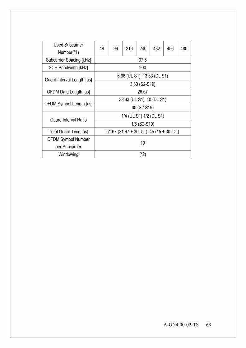
A-GN4.00-02-TS 63
Used Subcarrier Number(*1)
48 96 216 240 432 456 480
Subcarrier Spacing [kHz] 37.5 SCH Bandwidth [kHz] 900
Guard Interval Length [us] 6.66 (UL S1), 13.33 (DL S1)
3.33 (S2-S19) OFDM Data Length [us] 26.67
OFDM Symbol Length [us] 33.33 (UL S1), 40 (DL S1)
30 (S2-S19)
Guard Interval Ratio 1/4 (UL S1) 1/2 (DL S1)
1/8 (S2-S19) Total Guard Time [us] 51.67 (21.67 + 30; UL), 45 (15 + 30; DL)
OFDM Symbol Number per Subcarrier
19
Windowing (*2)
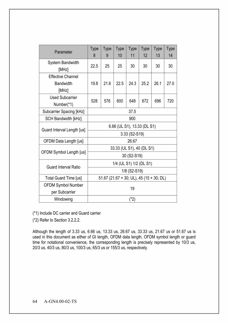
64 A-GN4.00-02-TS
Parameter Type
8 Type
9 Type10
Type11
Type12
Type13
Type14
System Bandwidth [MHz]
22.5 25 25 30 30 30 30
Effective Channel Bandwidth
[MHz] 19.8 21.6 22.5 24.3 25.2 26.1 27.0
Used Subcarrier Number(*1)
528 576 600 648 672 696 720
Subcarrier Spacing [kHz] 37.5 SCH Bandwidth [kHz] 900
Guard Interval Length [us] 6.66 (UL S1), 13.33 (DL S1)
3.33 (S2-S19) OFDM Data Length [us] 26.67
OFDM Symbol Length [us] 33.33 (UL S1), 40 (DL S1)
30 (S2-S19)
Guard Interval Ratio 1/4 (UL S1) 1/2 (DL S1)
1/8 (S2-S19) Total Guard Time [us] 51.67 (21.67 + 30; UL), 45 (15 + 30; DL)
OFDM Symbol Number per Subcarrier
19
Windowing (*2) (*1) Include DC carrier and Guard carrier (*2) Refer to Section 3.2.2.2. Although the length of 3.33 us, 6.66 us, 13.33 us, 26.67 us, 33.33 us, 21.67 us or 51.67 us is used in this document as either of GI length, OFDM data length, OFDM symbol length or guard time for notational convenience, the corresponding length is precisely represented by 10/3 us, 20/3 us, 40/3 us, 80/3 us, 100/3 us, 65/3 us or 155/3 us, respectively.
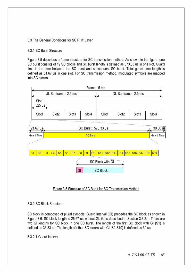
A-GN4.00-02-TS 65
3.3 The General Conditions for SC PHY Layer 3.3.1 SC Burst Structure Figure 3.5 describes a frame structure for SC transmission method. As shown in the figure, one SC burst consists of 19 SC blocks and SC burst length is defined as 573.33 us in one slot. Guard time is the time between the SC burst and subsequent SC burst. Total guard time length is defined as 51.67 us in one slot. For SC transmission method, modulated symbols are mapped into SC blocks.
Figure 3.5 Structure of SC Burst for SC Transmission Method
3.3.2 SC Block Structure SC block is composed of plural symbols. Guard Interval (GI) precedes the SC block as shown in Figure 3.6. SC block length is 26.67 us without GI. GI is described in Section 3.3.2.1. There are two GI lengths for SC block in one SC burst. The length of the first SC block with GI (S1) is defined as 33.33 us. The length of other SC blocks with GI (S2-S19) is defined as 30 us. 3.3.2.1 Guard Interval
Slot1 Slot2 Slot3 Slot4 Slot1 Slot2 Slot3 Slot4
625 us Slot :
UL Subframe : 2.5 ms DL Subframe : 2.5 ms Frame : 5 ms
S1
Guard Time
S19 S2 S3 S4 S5 S6 S7 S8 S9 S10 S11 S12 S13 S14 S15 S16 S17 S18
SC Burst : 573.33 us
GI SC Block
SC Block with GI
Guard Time SC Burst
21.67 us 30.00 us
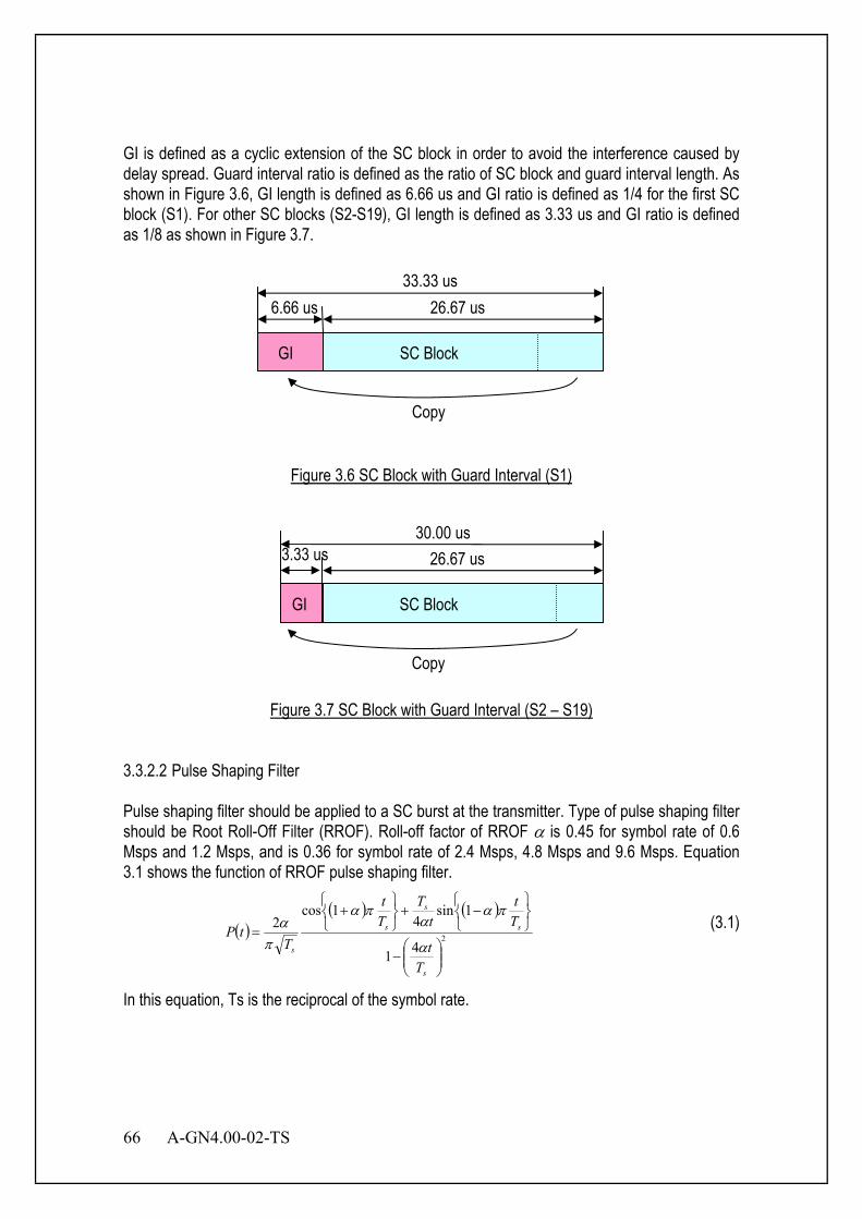
66 A-GN4.00-02-TS
GI is defined as a cyclic extension of the SC block in order to avoid the interference caused by delay spread. Guard interval ratio is defined as the ratio of SC block and guard interval length. As shown in Figure 3.6, GI length is defined as 6.66 us and GI ratio is defined as 1/4 for the first SC block (S1). For other SC blocks (S2-S19), GI length is defined as 3.33 us and GI ratio is defined as 1/8 as shown in Figure 3.7.
Figure 3.6 SC Block with Guard Interval (S1)
Figure 3.7 SC Block with Guard Interval (S2 – S19)
3.3.2.2 Pulse Shaping Filter Pulse shaping filter should be applied to a SC burst at the transmitter. Type of pulse shaping filter should be Root Roll-Off Filter (RROF). Roll-off factor of RROF α is 0.45 for symbol rate of 0.6 Msps and 1.2 Msps, and is 0.36 for symbol rate of 2.4 Msps, 4.8 Msps and 9.6 Msps. Equation 3.1 shows the function of RROF pulse shaping filter.
( )( ) ( )
241
1sin4
1cos2
−
−+
+=
s
s
s
s
s
Tt
Tt
tT
Tt
TtP
α
παα
πα
πα (3.1)
In this equation, Ts is the reciprocal of the symbol rate.
GI SC Block
3.33 us 26.67 us
Copy
30.00 us
GI SC Block
6.66 us 26.67 us
Copy
33.33 us
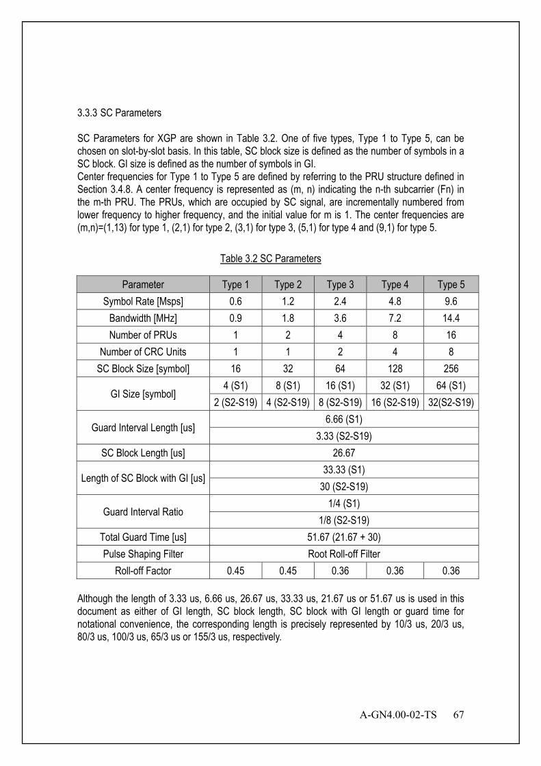
A-GN4.00-02-TS 67
3.3.3 SC Parameters SC Parameters for XGP are shown in Table 3.2. One of five types, Type 1 to Type 5, can be chosen on slot-by-slot basis. In this table, SC block size is defined as the number of symbols in a SC block. GI size is defined as the number of symbols in GI. Center frequencies for Type 1 to Type 5 are defined by referring to the PRU structure defined in Section 3.4.8. A center frequency is represented as (m, n) indicating the n-th subcarrier (Fn) in the m-th PRU. The PRUs, which are occupied by SC signal, are incrementally numbered from lower frequency to higher frequency, and the initial value for m is 1. The center frequencies are (m,n)=(1,13) for type 1, (2,1) for type 2, (3,1) for type 3, (5,1) for type 4 and (9,1) for type 5.
Table 3.2 SC Parameters
Parameter Type 1 Type 2 Type 3 Type 4 Type 5 Symbol Rate [Msps] 0.6 1.2 2.4 4.8 9.6
Bandwidth [MHz] 0.9 1.8 3.6 7.2 14.4 Number of PRUs 1 2 4 8 16
Number of CRC Units 1 1 2 4 8 SC Block Size [symbol] 16 32 64 128 256
GI Size [symbol] 4 (S1) 8 (S1) 16 (S1) 32 (S1) 64 (S1)
2 (S2-S19) 4 (S2-S19) 8 (S2-S19) 16 (S2-S19) 32(S2-S19)
Guard Interval Length [us] 6.66 (S1)
3.33 (S2-S19) SC Block Length [us] 26.67
Length of SC Block with GI [us] 33.33 (S1)
30 (S2-S19)
Guard Interval Ratio 1/4 (S1)
1/8 (S2-S19) Total Guard Time [us] 51.67 (21.67 + 30) Pulse Shaping Filter Root Roll-off Filter
Roll-off Factor 0.45 0.45 0.36 0.36 0.36 Although the length of 3.33 us, 6.66 us, 26.67 us, 33.33 us, 21.67 us or 51.67 us is used in this document as either of GI length, SC block length, SC block with GI length or guard time for notational convenience, the corresponding length is precisely represented by 10/3 us, 20/3 us, 80/3 us, 100/3 us, 65/3 us or 155/3 us, respectively.
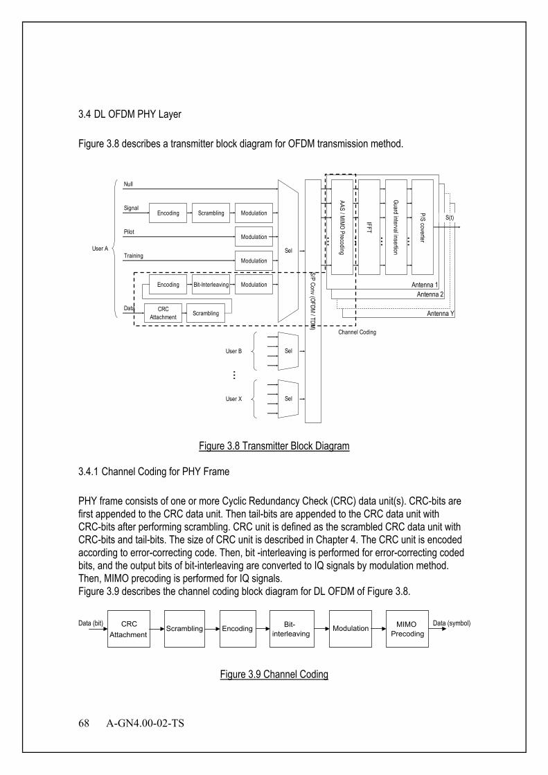
68 A-GN4.00-02-TS
3.4 DL OFDM PHY Layer Figure 3.8 describes a transmitter block diagram for OFDM transmission method.
Antenna Y
Antenna 2Antenna 1
Sel
Encoding Scrambling Modulation
...
Signal
ModulationPilot
TrainingModulation
Encoding Bit-Interleaving Modulation
Data CRCAttachment Scrambling
S/P Conv (OFDM / TDM)
AAS / MIMO Precoding
IFFT
Guard interval insertion
P/S coverter
S(t)
Channel Coding
Sel
Sel
Null
User A
User B
User X
...
... ... ... ...
Figure 3.8 Transmitter Block Diagram
3.4.1 Channel Coding for PHY Frame PHY frame consists of one or more Cyclic Redundancy Check (CRC) data unit(s). CRC-bits are first appended to the CRC data unit. Then tail-bits are appended to the CRC data unit with CRC-bits after performing scrambling. CRC unit is defined as the scrambled CRC data unit with CRC-bits and tail-bits. The size of CRC unit is described in Chapter 4. The CRC unit is encoded according to error-correcting code. Then, bit -interleaving is performed for error-correcting coded bits, and the output bits of bit-interleaving are converted to IQ signals by modulation method. Then, MIMO precoding is performed for IQ signals. Figure 3.9 describes the channel coding block diagram for DL OFDM of Figure 3.8.
Figure 3.9 Channel Coding
CRC Attachment Scrambling Encoding
interleaving Modulation Data (bit) Data (symbol) Bit- Precoding
MIMO
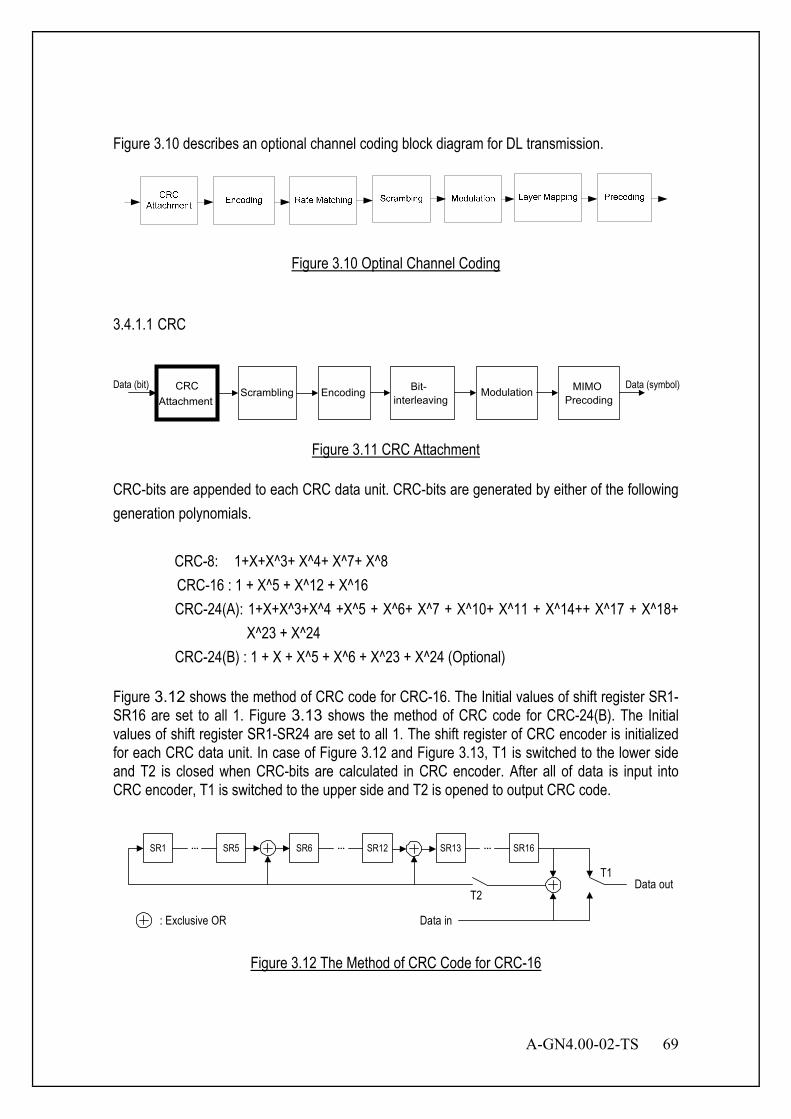
A-GN4.00-02-TS 69
Figure 3.10 describes an optional channel coding block diagram for DL transmission.
Figure 3.10 Optinal Channel Coding
3.4.1.1 CRC
Figure 3.11 CRC Attachment
CRC-bits are appended to each CRC data unit. CRC-bits are generated by either of the following generation polynomials.
CRC-8: 1+X+X^3+ X^4+ X^7+ X^8 CRC-16 : 1 + X^5 + X^12 + X^16 CRC-24(A): 1+X+X^3+X^4 +X^5 + X^6+ X^7 + X^10+ X^11 + X^14++ X^17 + X^18+
X^23 + X^24 CRC-24(B) : 1 + X + X^5 + X^6 + X^23 + X^24 (Optional)
Figure 3.12 shows the method of CRC code for CRC-16. The Initial values of shift register SR1- SR16 are set to all 1. Figure 3.13 shows the method of CRC code for CRC-24(B). The Initial values of shift register SR1-SR24 are set to all 1. The shift register of CRC encoder is initialized for each CRC data unit. In case of Figure 3.12 and Figure 3.13, T1 is switched to the lower side and T2 is closed when CRC-bits are calculated in CRC encoder. After all of data is input into CRC encoder, T1 is switched to the upper side and T2 is opened to output CRC code.
SR1 SR5 SR6... SR12... SR13 SR16...
T2Data out
Data in
T1
: Exclusive OR
Figure 3.12 The Method of CRC Code for CRC-16
Data (bit) CRC Attachment Scrambling Encoding
interleaving Modulation Data (symbol) Bit- Precoding
MIMO
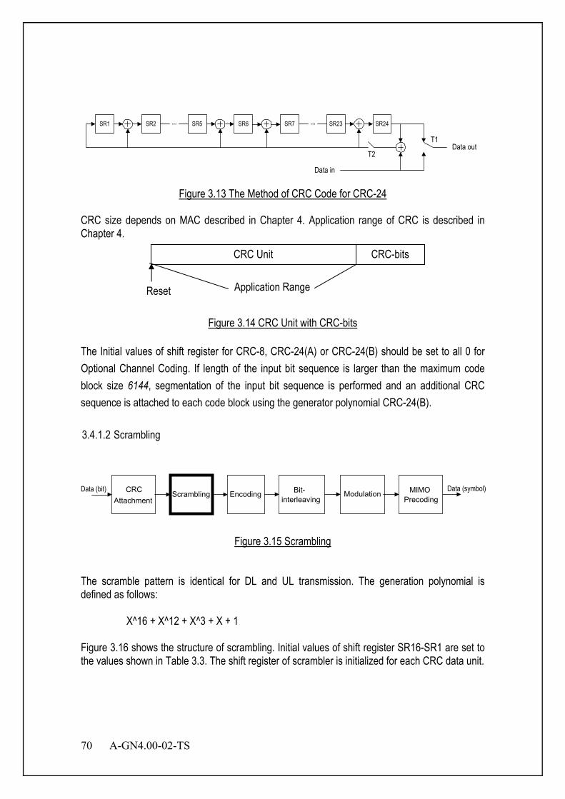
70 A-GN4.00-02-TS
SR1 SR2 SR5 SR6... SR7 SR23...
T2Data out
Data in
SR24
T1
Figure 3.13 The Method of CRC Code for CRC-24
CRC size depends on MAC described in Chapter 4. Application range of CRC is described in Chapter 4.
Figure 3.14 CRC Unit with CRC-bits
The Initial values of shift register for CRC-8, CRC-24(A) or CRC-24(B) should be set to all 0 for Optional Channel Coding. If length of the input bit sequence is larger than the maximum code block size 6144, segmentation of the input bit sequence is performed and an additional CRC sequence is attached to each code block using the generator polynomial CRC-24(B). 3.4.1.2 Scrambling
Figure 3.15 Scrambling
The scramble pattern is identical for DL and UL transmission. The generation polynomial is defined as follows:
X^16 + X^12 + X^3 + X + 1
Figure 3.16 shows the structure of scrambling. Initial values of shift register SR16-SR1 are set to the values shown in Table 3.3. The shift register of scrambler is initialized for each CRC data unit.
CRC Unit CRC-bits
Reset Application Range
Data (bit) CRC Attachment Scrambling Encoding
interleaving Modulation Data (symbol) Bit- Precoding
MIMO
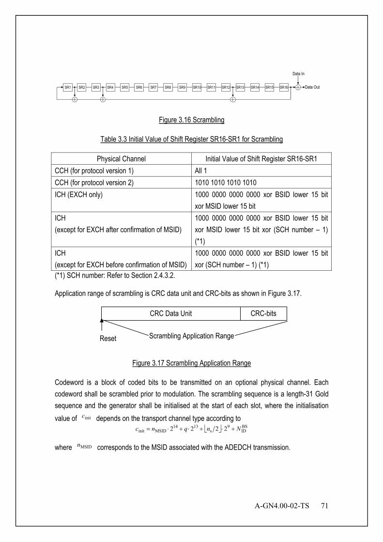
A-GN4.00-02-TS 71
Data Out
Data In
SR1 SR2 SR3 SR4 SR5 SR6 SR7 SR8 SR9 SR10 SR11 SR12 SR13 SR14 SR15 SR16
Figure 3.16 Scrambling
Table 3.3 Initial Value of Shift Register SR16-SR1 for Scrambling
Physical Channel Initial Value of Shift Register SR16-SR1 CCH (for protocol version 1) All 1 CCH (for protocol version 2) 1010 1010 1010 1010 ICH (EXCH only) 1000 0000 0000 0000 xor BSID lower 15 bit
xor MSID lower 15 bit ICH (except for EXCH after confirmation of MSID)
1000 0000 0000 0000 xor BSID lower 15 bit xor MSID lower 15 bit xor (SCH number – 1) (*1)
ICH (except for EXCH before confirmation of MSID)
1000 0000 0000 0000 xor BSID lower 15 bit xor (SCH number – 1) (*1)
(*1) SCH number: Refer to Section 2.4.3.2. Application range of scrambling is CRC data unit and CRC-bits as shown in Figure 3.17.
Figure 3.17 Scrambling Application Range
Codeword is a block of coded bits to be transmitted on an optional physical channel. Each codeword shall be scrambled prior to modulation. The scrambling sequence is a length-31 Gold sequence and the generator shall be initialised at the start of each slot, where the initialisation value of initc depends on the transport channel type according to
BSID
9s
1314MSIDinit 2222 Nnqnc +⋅+⋅+⋅=
where MSIDn corresponds to the MSID associated with the ADEDCH transmission.
CRC Data Unit CRC-bits
Reset Scrambling Application Range

72 A-GN4.00-02-TS
3.4.1.3 Encoding
Figure 3.18 Encoding
Error correction code methods are defined as described below. (a) Convolutional code (coding rate r=1/2) (Mandatory) (b) Convolutional code (coding rate r=1/3) (Optional) (c) Tail Biting Convolutional code (coding rate r=1/3) (d) Turbo code (Optional)
Table 3.4 summarizes the error correction code for physical channel.
Table 3.4 The Error Correction Code for Physical Channel
Physical channel Error correction code CCCH Convolutional code ANCH Convolutional code EXCH Convolutional/Turbo code CSCH Convolutional code
Data (bit) CRC Attachment Scrambling Encoding
interleaving Modulation Data (symbol) Bit- Precoding
MIMO

A-GN4.00-02-TS 73
3.4.1.3.1 Error Correction Encoding 3.4.1.3.1.1 Convolutional Code (coding rate r=1/2) (Mandatory) 3.4.1.3.1.1.1 Convolutional Encoder Constraint length of convolutional encoder is 7. Generation polynomials are G1=133 and G2=171 in octal representation. Figure 3.19 illustrates the constitution of convolutional encoder. For this figure, coding rate of convolutional coding becomes 1/2. The initial value of shift register in encoder is 6-bit 0. As an input to the encoder, tail-bits, which consist of 6-bit 0, are appended to the end of scrambled data bits.
INPUT I(k) OUTPUT A(k) OUTPUT B(k)
Figure 3.19 Generation Polynomial and Application Range of Convolutional Code
3.4.1.3.1.1.2 Puncturing Pattern Encoded bits are punctured in order to change coding rate. Table 3.5 describes puncturing pattern related with puncturing rate. In this table, 1 denotes the bits selected and 0 denotes the bits punctured. Figure 3.20 illustrates the puncturing procedure.
Table 3.5 Puncturing Pattern of Convolutional Code
I(k)
B(k)
A(k)
D D D D D D
Scrambled Data Reset
6bit
A(k)
B(k)
tail-bits

74 A-GN4.00-02-TS
1 3/4 4/6 6/10 8/14A 1 11 110 11010 1111010B 1 10 101 10101 1000101
Puncturing rate R2
I(1) I(2) A(1)A(2)
B(1)B(2) A(1)B(1)A(2)
I(1) I(2) I(3) A(1)A(2)A(3)
B(1)B(2)B(3) A(1)B(1)A(2)B(3)
I(1) I(2) I(3) I(4) I(5) A(1)A(2)A(3)A(4)A(5)
B(1)B(2)B(3)B(4)B(5)
A(1)B(1)A(2)B(3)A(4)B(5)
I(1) I(2) I(3) I(4) I(5) I(6) I(7)
A(1)A(2)A(3)A(4)A(5)A(6)A(7)
B(1)B(2)B(3)B(4)B(5)B(6)B(7)
A(1)B(1)A(2)A(3)A(4)B(5)A(6)B(7)
R2=6/10
R2=8/14
R2=3/4
R2=4/6
Figure 3.20 Puncturing Procedure for Convolutional Code
3.4.1.3.1.2 Convolutional Code (coding rate r=1/3) (Optional) 3.4.1.3.1.2.1 Convolutional Encoder Constraint length of convolutional encoder is 7. Generation polynomials are G1=133, G2=171 and G3=165 in octal representation. Figure 3.21 illustrates the constitution of convolutional encoder. For this figure, coding rate of convolutional coding becomes 1/3. The initial value of shift register in encoder is 6-bit 0. As an input to the encoder, tail-bits, which consist of 6-bit 0, are appended to the end of scrambled data bits.
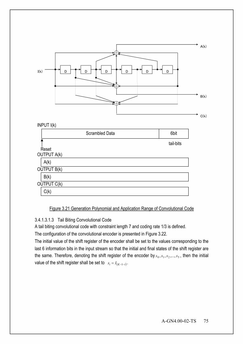
A-GN4.00-02-TS 75
INPUT I(k) OUTPUT A(k) OUTPUT B(k) OUTPUT C(k)
Figure 3.21 Generation Polynomial and Application Range of Convolutional Code
3.4.1.3.1.3 Tail Biting Convolutional Code A tail biting convolutional code with constraint length 7 and coding rate 1/3 is defined. The configuration of the convolutional encoder is presented in Figure 3.22. The initial value of the shift register of the encoder shall be set to the values corresponding to the last 6 information bits in the input stream so that the initial and final states of the shift register are the same. Therefore, denoting the shift register of the encoder by 5210 ,...,,, ssss , then the initial value of the shift register shall be set to ( )iKi Is −−= 1 .
I(k)
B(k)
A(k)
D D D D D D
Scrambled Data
Reset
6bit
tail-bits
C(k)
A(k)
B(k)
C(k)
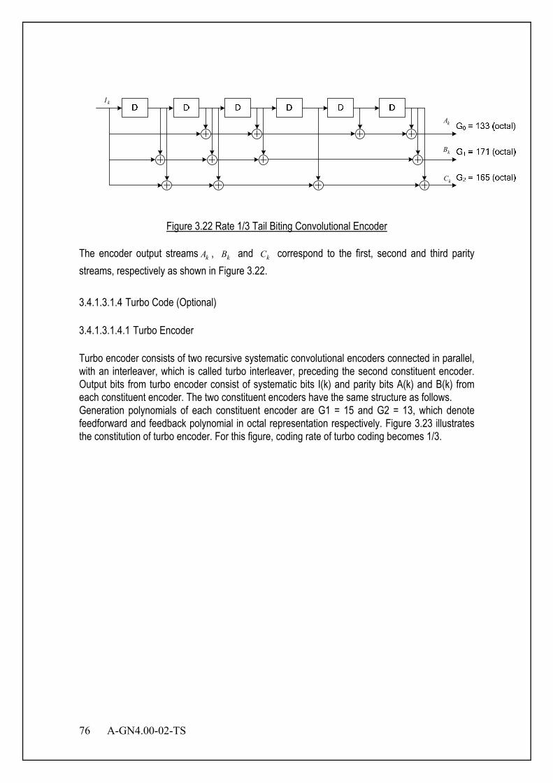
76 A-GN4.00-02-TS
kI
kA
kB
kC
Figure 3.22 Rate 1/3 Tail Biting Convolutional Encoder
The encoder output streams kA , kB and kC correspond to the first, second and third parity streams, respectively as shown in Figure 3.22. 3.4.1.3.1.4 Turbo Code (Optional) 3.4.1.3.1.4.1 Turbo Encoder Turbo encoder consists of two recursive systematic convolutional encoders connected in parallel, with an interleaver, which is called turbo interleaver, preceding the second constituent encoder. Output bits from turbo encoder consist of systematic bits I(k) and parity bits A(k) and B(k) from each constituent encoder. The two constituent encoders have the same structure as follows. Generation polynomials of each constituent encoder are G1 = 15 and G2 = 13, which denote feedforward and feedback polynomial in octal representation respectively. Figure 3.23 illustrates the constitution of turbo encoder. For this figure, coding rate of turbo coding becomes 1/3.
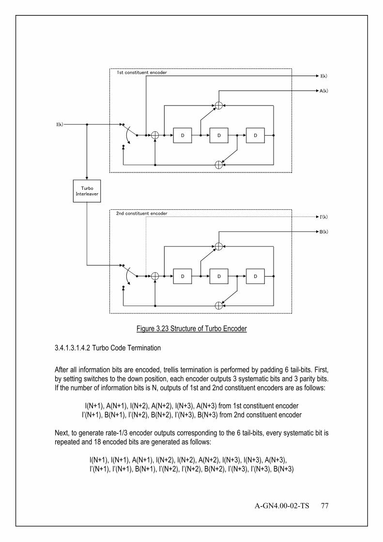
A-GN4.00-02-TS 77
I(k)
D D D
TurboInterleaver
1st constituent encoder
2nd constituent encoderI'(k)
B(k)
D D D
I(k)
A(k)
Figure 3.23 Structure of Turbo Encoder
3.4.1.3.1.4.2 Turbo Code Termination After all information bits are encoded, trellis termination is performed by padding 6 tail-bits. First, by setting switches to the down position, each encoder outputs 3 systematic bits and 3 parity bits. If the number of information bits is N, outputs of 1st and 2nd constituent encoders are as follows:
I(N+1), A(N+1), I(N+2), A(N+2), I(N+3), A(N+3) from 1st constituent encoder I’(N+1), B(N+1), I’(N+2), B(N+2), I’(N+3), B(N+3) from 2nd constituent encoder
Next, to generate rate-1/3 encoder outputs corresponding to the 6 tail-bits, every systematic bit is repeated and 18 encoded bits are generated as follows:
I(N+1), I(N+1), A(N+1), I(N+2), I(N+2), A(N+2), I(N+3), I(N+3), A(N+3), I’(N+1), I’(N+1), B(N+1), I’(N+2), I’(N+2), B(N+2), I’(N+3), I’(N+3), B(N+3)
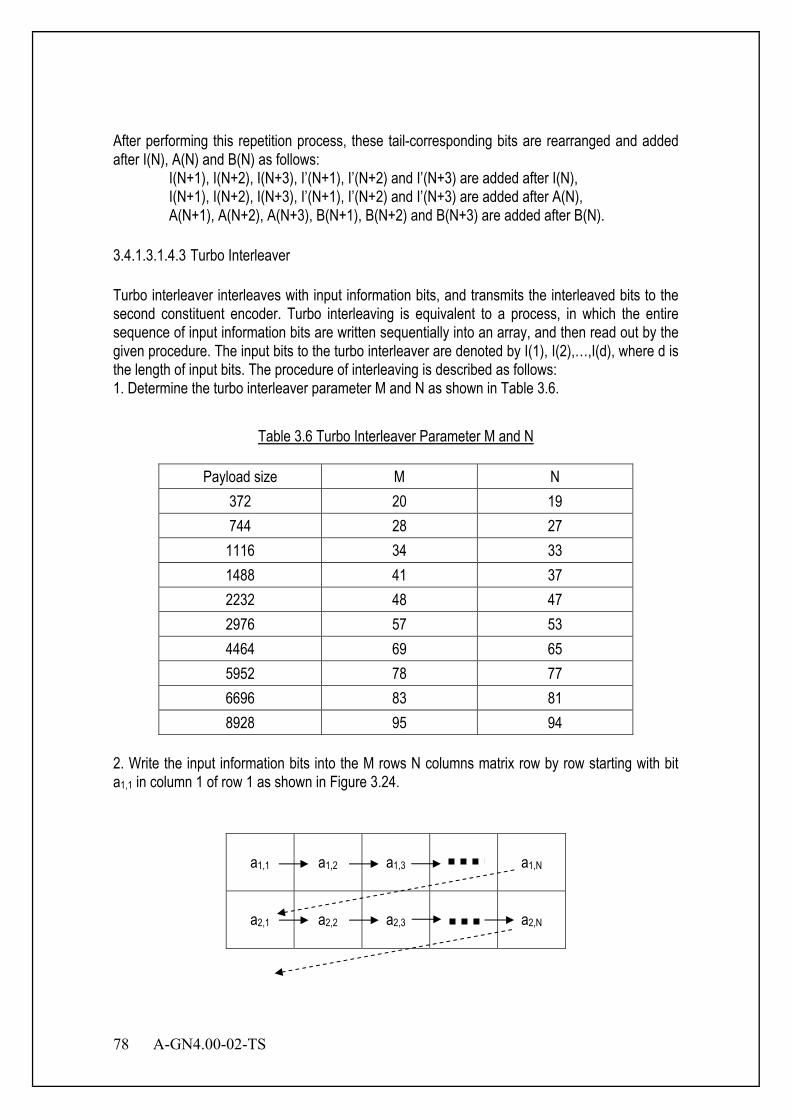
78 A-GN4.00-02-TS
After performing this repetition process, these tail-corresponding bits are rearranged and added after I(N), A(N) and B(N) as follows: I(N+1), I(N+2), I(N+3), I’(N+1), I’(N+2) and I’(N+3) are added after I(N), I(N+1), I(N+2), I(N+3), I’(N+1), I’(N+2) and I’(N+3) are added after A(N), A(N+1), A(N+2), A(N+3), B(N+1), B(N+2) and B(N+3) are added after B(N). 3.4.1.3.1.4.3 Turbo Interleaver Turbo interleaver interleaves with input information bits, and transmits the interleaved bits to the second constituent encoder. Turbo interleaving is equivalent to a process, in which the entire sequence of input information bits are written sequentially into an array, and then read out by the given procedure. The input bits to the turbo interleaver are denoted by I(1), I(2),…,I(d), where d is the length of input bits. The procedure of interleaving is described as follows: 1. Determine the turbo interleaver parameter M and N as shown in Table 3.6.
Table 3.6 Turbo Interleaver Parameter M and N
Payload size M N 372 20 19 744 28 27
1116 34 33 1488 41 37 2232 48 47 2976 57 53 4464 69 65 5952 78 77 6696 83 81 8928 95 94
2. Write the input information bits into the M rows N columns matrix row by row starting with bit a1,1 in column 1 of row 1 as shown in Figure 3.24.
a1,1
a1,2
a1,3
a1,N
a2,1
a2,2
a2,3
a2,N
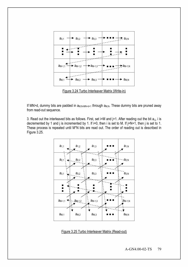
A-GN4.00-02-TS 79
a3,1
a3,2
a3,3
a3,N
aM-1,1
aM-1,2
aM-1,3
aM-1,N
aM,1
aM,2
aM,3
aM,N
Figure 3.24 Turbo Interleaver Matrix (Write-in)
If MN>d, dummy bits are padded in aM,N-MN+d+1 through aM,N. These dummy bits are pruned away from read-out sequence. 3. Read out the interleaved bits as follows. First, set i=M and j=1. After reading out the bit ai,j, i is decremented by 1 and j is incremented by 1. If i=0, then i is set to M. If j=N+1, then j is set to 1. These process is repeated until M*N bits are read out. The order of reading out is described in Figure 3.25.
a1,1
a1,2
a1,3
a1,N
a2,1
a2,2
a2,3
a2,N
a3,1
a3,2
a3,3
a3,N
aM-1,1
aM-1,2
aM-1,3
aM-1,N
aM,1
aM,2
aM,3
aM,N
Figure 3.25 Turbo Interleaver Matrix (Read-out)

80 A-GN4.00-02-TS
Another optional procedure of interleaving is described as follows: the output index j and the input index I(j) of the Turbo Interleaver satisfies the following quadratic form:
( ) KjfjfjI mod)( 221 ⋅+⋅=
Where the parameters 1f and 2f depend on the block size K. The block size K is from 40 to 6144. 4. Remove the dummy bits padded in 2. The number of the read-out bits is M*N after reading out all the written bits, and the number of dummy bits is M*N-d after deleting the padded dummy bits. Hence, the total number of output bits becomes d. 3.4.1.3.1.4.4 Puncturing pattern Punctured turbo encoded bits consist of systematic bits and punctured parity bits. Assume that coding rate R2 is k/(k+1), while k is 1, 2, 3, 5 and 7 parity bits are selected in every 2*k parity bits at each constituent encoder, except for the case of k being 7. In case of k being 7, puncturing pattern has to be specified so that all trellis state will be appeared because period of feedback polynomial at each constituent encoder is 7. Table 3.7 describes puncturing patterns at each coding rate. P(m1 m2 … ,n1 n2 …) represents that (m1,m2,…)-th parity bits are selected in every 2*k parity bits at the first constituent encoder and (n1,n2,…)-th parity bits are selected in every 2*k parity bits at the second constituent encoder, while k is 1, 2, 3 and 5. While k is 7, (m1,m2,…)-th parity bits are selected in every 98 parity bits at the first constituent encoder and (n1,n2,…)-th parity bits are selected in every 98 parity bits at the second constituent encoder. Figure 3.26 illustrates the punctured turbo procedure with encoded bits while R2 is 1/2, 2/3, 3/4 and 5/6. Figure 3.27 illustrates the punctured turbo coding procedure while R2 is 7/8. As shown in Figure 3.27, a parity bit is selected from every 15 bits in 98 parity bits at each constituent encoder.
Table 3.7 Coding Rate and Puncturing Pattern
Coding Rate Puncturing Pattern1/2 P(1,2)2/3 P(1,3)3/4 P(1,4)5/6 P(1,6)7/8 P(1 16 31 46 61 76 91,8 23 38 53 68 83 98)

A-GN4.00-02-TS 81
I(1) I(2) I(1) I(2)
A(1) A(2) A(1) A(2) I(1) A(1) I(2) B(2)
B(1) B(2) B(1) B(2)
I(1) I(2) I(3) I(4) I(1) I(2) I(3) I(4)
A(1) A(2) A(3) A(4) A(1) A(2) A(3) A(4) I(1) A(1) I(2) I(3) B(3) I(4)
B(1) B(2) B(3) B(4) B(1) B(2) B(3) B(4)
I(1) I(2) I(3) I(4) I(5) I(6) I(1) I(2) I(3) I(4) I(5) I(6)
A(1) A(2) A(3) A(4) A(5) A(6) A(1) A(2) A(3) A(4) A(5) A(6) I(1) A(1) I(2) I(3) I(4) B(4) I(5) I(6)
B(1) B(2) B(3) B(4) B(5) B(6) B(1) B(2) B(3) B(4) B(5) B(6)
I(1) I(2) I(3) I(4) I(5) I(6) I(7) I(8) I(9) I(10) I(1) I(2) I(3) I(4) I(5) I(6) I(7) I(8) I(9) I(10)
A(1) A(2) A(3) A(4) A(5) A(6) A(7) A(8) A(9) A(10) A(1) A(2) A(3) A(4) A(5) A(6) A(7) A(8) A(9) A(10)
B(1) B(2) B(3) B(4) B(5) B(6) B(7) B(8) B(9) B(10) B(1) B(2) B(3) B(4) B(5) B(6) B(7) B(8) B(9) B(10)
I(1) A(1) I(2) I(3) I(4) I(5) I(6) B(6) I(7) I(8) I(9) I(10)
R2=2/3
R2=1/2
R2=3/4
R2=5/6
Figure 3.26 Puncturing Procedure while R2 is 1/2, 2/3, 3/4 and 5/6
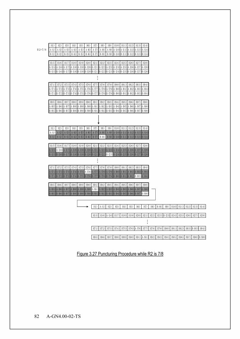
82 A-GN4.00-02-TS
I(1) I(2) I(3) I(4) I(5) I(6) I(7) I(8) I(9) I(10) I(11) I(12) I(13) I(14)
A(1) A(2) A(3) A(4) A(5) A(6) A(7) A(8) A(9) A(10)A(11)A(12)A(13)A(14)
B(1) B(2) B(3) B(4) B(5) B(6) B(7) B(8) B(9) B(10)B(11)B(12)B(13)B(14)
I(15) I(16) I(17) I(18) I(19) I(20) I(21) I(22) I(23) I(24) I(25) I(26) I(27) I(28)
A(15)A(16)A(17)A(18)A(19)A(20)A(21)A(22)A(23)A(24)A(25)A(26)A(27)A(28)
B(15)B(16)B(17)B(18)B(19)B(20)B(21)B(22)B(23)B(24)B(25)B(26)B(27)B(28)
I(71) I(72) I(73) I(74) I(75) I(76) I(77) I(78) I(79) I(80) I(81) I(82) I(83) I(84)
A(71)A(72)A(73)A(74)A(75)A(76)A(77)A(78)A(79)A(80)A(81)A(82)A(83)A(84)
B(71)B(72)B(73)B(74)B(75)B(76)B(77)B(78)B(79)B(80)B(81)B(82)B(83)B(84)
I(85) I(86) I(87) I(88) I(89) I(90) I(91) I(92) I(93) I(94) I(95) I(96) I(97) I(98)
A(85)A(86)A(87)A(88)A(89)A(90)A(91)A(92)A(93)A(94)A(95)A(96)A(97)A(98)
B(85)B(86)B(87)B(88)B(89)B(90)B(91)B(92)B(93)B(94)B(95)B(96)B(97)B(98)
I(1) A(1) I(2) I(3) I(4) I(5) I(6) I(7) I(8) B(8) I(9) I(10) I(11) I(12) I(13) I(14)
I(15) I(16) A(16) I(17) I(18) I(19) I(20) I(21) I(22) I(23) B(23) I(24) I(25) I(26) I(27) I(28)
I(71) I(72) I(73) I(74) I(75) I(76) A(76) I(77) I(78) I(79) I(80) I(81) I(82) I(83) B(83) I(84)
I(85) I(86) I(87) I(88) I(89) I(90) I(91) A(91) I(92) I(93) I(94) I(95) I(96) I(97) I(98) B(98)
…
R2=7/8
……
Figure 3.27 Puncturing Procedure while R2 is 7/8

A-GN4.00-02-TS 83
3.4.1.4 Bit-interleaving
Figure 3.28 Interleaving
3.4.1.4.1 Bit-interleaver Structure
Figure 3.29 illustrates the application range of bit-interleaving. In this figure, the parameter b(1),…,b(xy) is the bit series after encoding. The number of input bits to the interleaver is x*y, where the parameter x is the number of bits in a symbol and the parameter y is the number of symbols(*1). The bit-interleaver unit consists of x block interleavers. Each block interleaver interleaves y bits separately. The details on the block interleaver are described in Section 3.4.1.4.2. (*1) In case of BPSK or π/2-BPSK with coding rate of 2/3 for CSCH, one dummy bit of 0 is appended to the end of the punctured bits. In other cases, the punctured bits equal to the input bits of bit-interleaver.
Figure 3.29 Application Range of Bit-interleaving
CRC Attachment Scrambling Encoding
interleaving Modulation Data (bit) Data (symbol) Bit- Precoding
MIMO
b(1) … b(y) b(y+1) … b(2y)
… b((x-1)y+1)…b(xy)
The Number of Input Bits to Bit-interleaver
Bit-interleaver Unit 1
Start Bit
Bit-interleaver Unit x
Bit-interleaver Unit 1 (Block Interleaver)
…

84 A-GN4.00-02-TS
3.4.1.4.2 Block Interleaver Method Block interleaver is used for each y bits in each column as explained in
Figure 3.29. Input bits are written sequentially into an array per bit in symbol, and then read out by the given procedure. The number of input bits to the interleaver depends on symbol size of physical channel and modulation class. The procedure of interleaving is described as follows: 1. Determine the interleaver parameter x and y based on the number of input bits and
modulation class. 2. Determine the block interleaver parameter N and M for each physical channel, where y= N*M,
N is column size, and M is row size. 3. Write the input information bits into the M-row N-column matrix row. Write starting position
shall be set according to bit position i (i=1,…,x) in a symbol. Figure 3.30 illustrates block interleaver matrix for writing in case of n being 1.
4. Read the written bits from the M-row N-column matrix row to interleave each bit in symbol and each symbol. Read starting position shall be set according to bit position in a symbol.
Figure 3.31 illustrates a block interleaver matrix for reading in case n being 1.
a1,1
a1,2
a1,3
a1,N
a2,1
a2,2
a2,3
a2,N
a3,1
a3,2
a3,3
a3,N
aM-1,1
aM-1,2
aM-1,3
aM-1,N
aM,1
aM,2
aM,3
aM,N
Figure 3.30 Interleaver Matrix (Write-in) in case of n being 1
Position to Start Writing
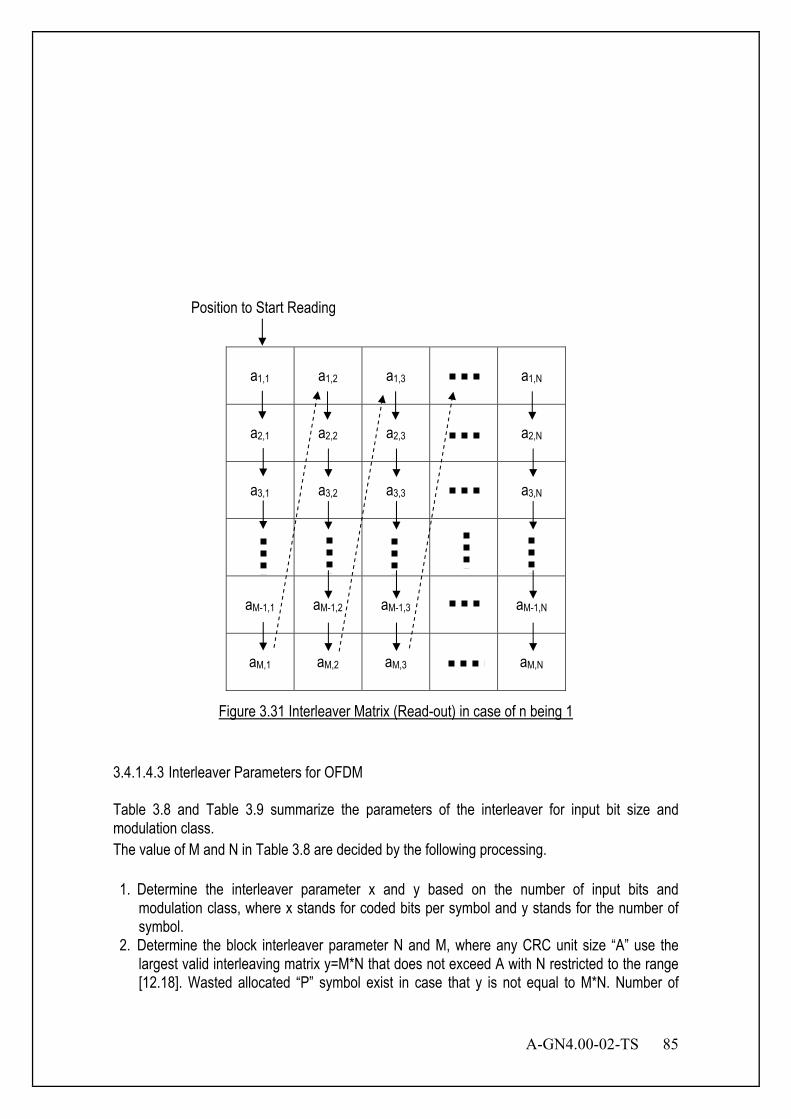
A-GN4.00-02-TS 85
a1,1
a1,2
a1,3
a1,N
a2,1
a2,2
a2,3
a2,N
a3,1
a3,2
a3,3
a3,N
aM-1,1
aM-1,2
aM-1,3
aM-1,N
aM,1
aM,2
aM,3
aM,N
Figure 3.31 Interleaver Matrix (Read-out) in case of n being 1
3.4.1.4.3 Interleaver Parameters for OFDM Table 3.8 and Table 3.9 summarize the parameters of the interleaver for input bit size and modulation class. The value of M and N in Table 3.8 are decided by the following processing. 1. Determine the interleaver parameter x and y based on the number of input bits and
modulation class, where x stands for coded bits per symbol and y stands for the number of symbol.
2. Determine the block interleaver parameter N and M, where any CRC unit size “A” use the largest valid interleaving matrix y=M*N that does not exceed A with N restricted to the range [12.18]. Wasted allocated “P” symbol exist in case that y is not equal to M*N. Number of
Position to Start Reading

86 A-GN4.00-02-TS
columns “N” is determined by choosing N from [13,12,18,17,16,15,14], such that P=y-floor(y/N)*N is minimized. If N that P is minimized exists more than one value, N selects first number of permutation [13,12,18,17,16,15,14]. The number of row “M” is defined by equation M=floor(y/N). M*N denotes size of a block interleaver.
Note: It is not P=0 in case of y=358 and 366 as shown Table 3.8. This means the number of data symbols “y” is not the same as interleave size “M*N”. In this case, “y-M*N” data symbols are processed as DTX.
Table 3.8 Interleaver Parameter M, N and P
Number of Symbols y
M N P
324 27 12 0 340 20 17 0 348 29 12 0 358 21 17 1 364 28 13 0 366 28 13 2 372 31 12 0 384 32 12 0 390 30 13 0 408 34 12 0 696 58 12 0 744 62 12 0 750 50 15 0 768 64 12 0 780 60 13 0 798 57 14 0 816 68 12 0
Table 3.9 Interleaver Parameter
Modulation The Number of Block Interleavers BPSK 1 QPSK 2 16QAM 4 64QAM 6 256QAM 8
Table 3.10 summarizes the definition of bit position i (i=1,..,x) in a symbol.
Table 3.10 The Definition of Bit Position i in a Symbol
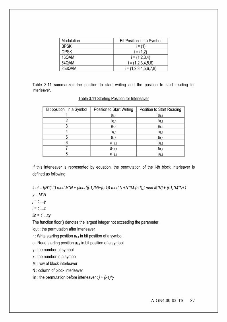
A-GN4.00-02-TS 87
Modulation Bit Position i in a Symbol BPSK i = (1) QPSK i = (1,2) 16QAM i = (1,2,3,4) 64QAM i = (1,2,3,4,5,6) 256QAM i = (1,2,3,4,5,6,7,8)
Table 3.11 summarizes the position to start writing and the position to start reading for interleaver.
Table 3.11 Starting Position for Interleaver
Bit position i in a Symbol Position to Start Writing Position to Start Reading 1 a1,1 a1,1 2 a3,1 a1,2 3 a5,1 a1,3 4 a7,1 a1,4 5 a9,1 a1,5 6 a11,1 a1,6 7 a13,1 a1,7 8 a15,1 a1,8
If this interleaver is represented by equation, the permutation of the i-th block interleaver is defined as following. lout = [{N*(j-1) mod M*N + (floor((j-1)/M)+(c-1)) mod N +N*(M-(r-1))} mod M*N] + (i-1)*M*N+1 y = M*N j = 1,..,y i = 1,..,x lin = 1,..,xy The function floor() denotes the largest integer not exceeding the parameter. lout : the permutation after interleaver r : Write starting position ar,1 in bit position of a symbol c : Read starting position a1,c in bit position of a symbol y : the number of symbol x : the number in a symbol M : row of block interleaver N : column of block interleaver lin : the permutation before interleaver : j + (i-1)*y

88 A-GN4.00-02-TS
For the parameter r and c, refer to Table 3.11 and Table 3.39. The procedure of interleaving is performed as following: 1. Set j = 1 and i = 1. Then increase j to y. 2. Set j = 1 and i = i +1. Then increase j to y. 3. Repeat 2 until i equals to x.

A-GN4.00-02-TS 89
3.4.1.4.4 Output-bits after Bit-interleaver The IQ data symbol is generated by using x bits, each of which is taken from each block interleaver. Denote the output bits from i-th block interleaver by z(i,1), z(i,2), …, z(i,y). Thus, the j-th IQ data symbol is converted from the bit series z(p1,j), z(p2,j),…,z(px,j), where pi is an offset value to circulate the order of input bits to the modulator. The process is defined as follows: Input bits to the modulator: z(p1,j), z(p2,j),…,z(px,j) Offset value: pi = ( (i+j-2) mod x)+1 3.4.1.4.5 Bit-interleaving and Rate matching 3.4.1.4.5.1 Bit-interleaver Structure The rate matching for convolutionally coded transport channels and control information consists
of interleaving the three bit streams, )0(kd , )1(
kd and )2(kd , followed by the collection of bits and
the generation of a circular buffer. The bit stream )0(kd is interleaved according to the sub-block
interleaver with an output sequence defined as )0(1
)0(2
)0(1
)0(0 ,...,,, −ΠKvvvv .The bit stream )1(
kd is
interleaved according to the sub-block interleaver with an output sequence defined
as )1(1
)1(2
)1(1
)1(0 ,...,,, −ΠKvvvv . The bit stream )2(
kd is interleaved according to the sub-block
interleaver with an output sequence defined as )2(1
)2(2
)2(1
)2(0 ,...,,, −ΠKvvvv .
3.4.1.4.5.2 Block Interleaver Method The output bit sequence from the block interleaver is derived as follows:
(1) D is the number of bits input to the block interleaver.Determine the number of rows of the
matrix R, by finding minimum integer R such that ( )CRD ×≤ .
(2) If ( ) DCR >× , then ( )DCRND −×= dummy bits are padded. )(i
kkN dyD
=+ , k = 0,
1,…, D-1, and the bit sequence yk is written into the matrix row by row starting with bit y0 in column 0 of row 0.

90 A-GN4.00-02-TS
(3) Perform the inter-column permutation for the matrix based on the pattern >< )31(),...,1(),0( PPP = < 1, 17, 9, 25, 5, 21, 13, 29, 3, 19, 11, 27, 7, 23, 15, 31, 0, 16,
8, 24, 4, 20, 12, 28, 2, 18, 10, 26, 6, 22, 14, 30 >.
(4) The output of the block interleaver is the bit sequence read out column by column from the inter-column permuted matrix.
This block interleaver is also used in interleaving ADEDCH modulation symbols. In that case, the input bit sequence consists of ADEDCH symbol quadruplets. 3.4.1.4.5.3 Output-bits after Bit-interleaver
The circular buffer of length Π= KK w 3 is generated as follows:
)0(kk vw = , )1(
kkK vw =+Π, )2(
2 kkK vw =+Π, for k = 0,…, 1−ΠK
Denoting by E the rate matching output sequence length, the rate matching output bit sequence is ke , k = 0,1,..., 1−E . The procedure of ke is shown as Figure 3.32.
>≠< NULLwwKj mod
1
,mod
+=
=
kk
wewKjk
1+= jj
Figure 3.32 Procedure of Rate Matching Output Sequence
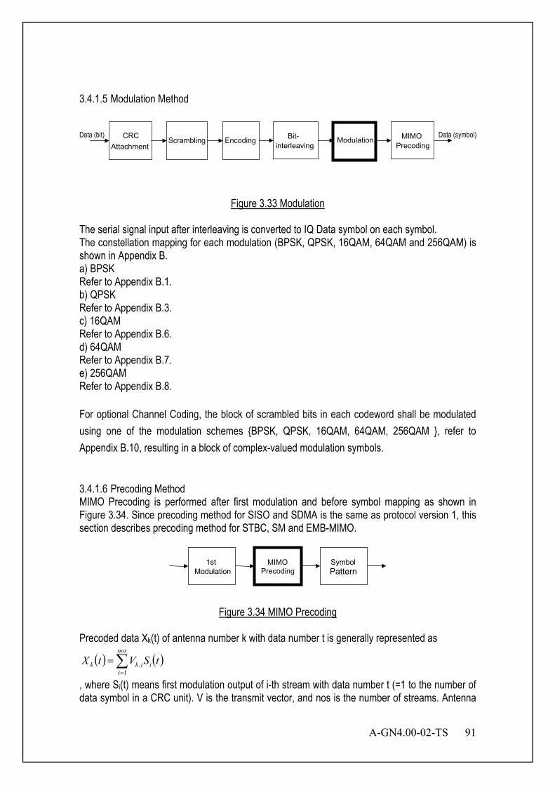
A-GN4.00-02-TS 91
3.4.1.5 Modulation Method
Figure 3.33 Modulation
The serial signal input after interleaving is converted to IQ Data symbol on each symbol. The constellation mapping for each modulation (BPSK, QPSK, 16QAM, 64QAM and 256QAM) is shown in Appendix B. a) BPSK Refer to Appendix B.1. b) QPSK Refer to Appendix B.3. c) 16QAM Refer to Appendix B.6. d) 64QAM Refer to Appendix B.7. e) 256QAM Refer to Appendix B.8. For optional Channel Coding, the block of scrambled bits in each codeword shall be modulated using one of the modulation schemes {BPSK, QPSK, 16QAM, 64QAM, 256QAM }, refer to Appendix B.10, resulting in a block of complex-valued modulation symbols. 3.4.1.6 Precoding Method MIMO Precoding is performed after first modulation and before symbol mapping as shown in Figure 3.34. Since precoding method for SISO and SDMA is the same as protocol version 1, this section describes precoding method for STBC, SM and EMB-MIMO.
Figure 3.34 MIMO Precoding
Precoded data Xk(t) of antenna number k with data number t is generally represented as
( ) ( )tSVtX i
nos
iikk ∑
=
=1
,
, where Si(t) means first modulation output of i-th stream with data number t (=1 to the number of data symbol in a CRC unit). V is the transmit vector, and nos is the number of streams. Antenna
CRC Attachment Scrambling Encoding
interleaving Modulation Data (bit) Data (symbol) Bit- Precoding
MIMO
MIMO Precoding
Symbol Pattern
1st Modulation
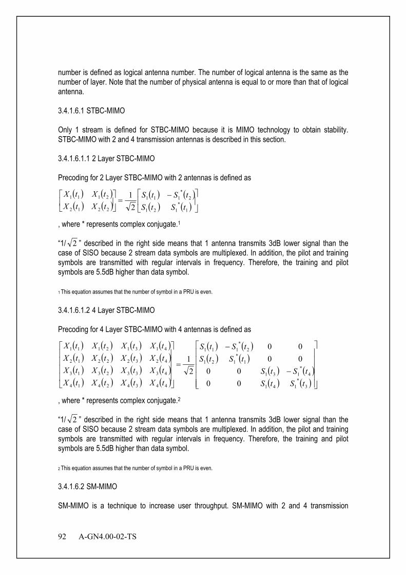
92 A-GN4.00-02-TS
number is defined as logical antenna number. The number of logical antenna is the same as the number of layer. Note that the number of physical antenna is equal to or more than that of logical antenna. 3.4.1.6.1 STBC-MIMO Only 1 stream is defined for STBC-MIMO because it is MIMO technology to obtain stability. STBC-MIMO with 2 and 4 transmission antennas is described in this section. 3.4.1.6.1.1 2 Layer STBC-MIMO Precoding for 2 Layer STBC-MIMO with 2 antennas is defined as
( ) ( )( ) ( )
( ) ( )( ) ( )
−=
1*
121
2*
111
2212
2111
21
tStStStS
tXtXtXtX
, where * represents complex conjugate.1 “1/ 2 ” described in the right side means that 1 antenna transmits 3dB lower signal than the case of SISO because 2 stream data symbols are multiplexed. In addition, the pilot and training symbols are transmitted with regular intervals in frequency. Therefore, the training and pilot symbols are 5.5dB higher than data symbol. 1 This equation assumes that the number of symbol in a PRU is even. 3.4.1.6.1.2 4 Layer STBC-MIMO Precoding for 4 Layer STBC-MIMO with 4 antennas is defined as
( ) ( ) ( ) ( )( ) ( ) ( ) ( )( ) ( ) ( ) ( )( ) ( ) ( ) ( )
( ) ( )( ) ( )
( ) ( )( ) ( )
−
−
=
3*
141
4*
131
1*
121
2*
111
44342414
43332313
42322212
41312111
0000
0000
21
tStStStS
tStStStS
tXtXtXtXtXtXtXtXtXtXtXtXtXtXtXtX
, where * represents complex conjugate.2
“1/ 2 ” described in the right side means that 1 antenna transmits 3dB lower signal than the case of SISO because 2 stream data symbols are multiplexed. In addition, the pilot and training symbols are transmitted with regular intervals in frequency. Therefore, the training and pilot symbols are 5.5dB higher than data symbol. 2 This equation assumes that the number of symbol in a PRU is even. 3.4.1.6.2 SM-MIMO SM-MIMO is a technique to increase user throughput. SM-MIMO with 2 and 4 transmission
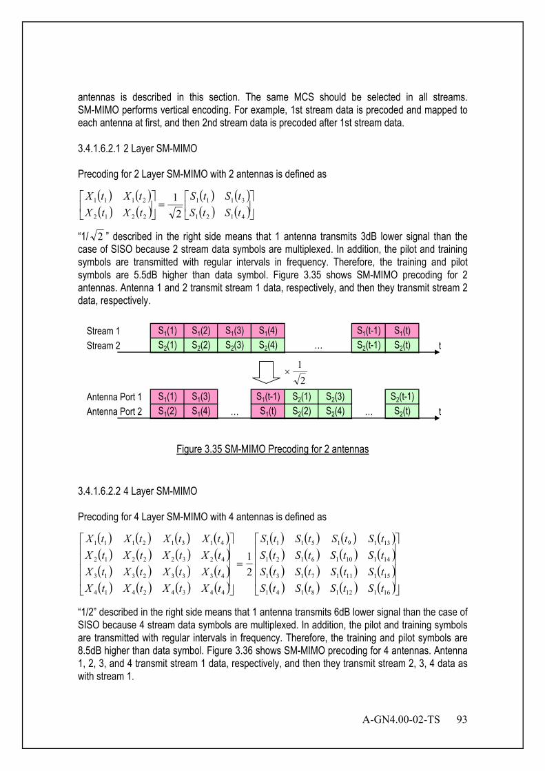
A-GN4.00-02-TS 93
antennas is described in this section. The same MCS should be selected in all streams. SM-MIMO performs vertical encoding. For example, 1st stream data is precoded and mapped to each antenna at first, and then 2nd stream data is precoded after 1st stream data. 3.4.1.6.2.1 2 Layer SM-MIMO Precoding for 2 Layer SM-MIMO with 2 antennas is defined as
( ) ( )( ) ( )
( ) ( )( ) ( )
=
4121
3111
2212
2111
21
tStStStS
tXtXtXtX
“1/ 2 ” described in the right side means that 1 antenna transmits 3dB lower signal than the case of SISO because 2 stream data symbols are multiplexed. In addition, the pilot and training symbols are transmitted with regular intervals in frequency. Therefore, the training and pilot symbols are 5.5dB higher than data symbol. Figure 3.35 shows SM-MIMO precoding for 2 antennas. Antenna 1 and 2 transmit stream 1 data, respectively, and then they transmit stream 2 data, respectively.
Stream 1 S1(1) S1(2) S1(3) S1(4) S1(t-1) S1(t)Stream 2 S2(1) S2(2) S2(3) S2(4) S2(t-1) S2(t) t
Antenna Port 1 S1(1) S1(3) S1(t-1) S2(1) S2(3) S2(t-1)Antenna Port 2 S1(2) S1(4) … S1(t) S2(2) S2(4) … S2(t) t
…
21
×
Figure 3.35 SM-MIMO Precoding for 2 antennas
3.4.1.6.2.2 4 Layer SM-MIMO Precoding for 4 Layer SM-MIMO with 4 antennas is defined as
( ) ( ) ( ) ( )( ) ( ) ( ) ( )( ) ( ) ( ) ( )( ) ( ) ( ) ( )
( ) ( ) ( ) ( )( ) ( ) ( ) ( )( ) ( ) ( ) ( )( ) ( ) ( ) ( )
=
1611218141
1511117131
1411016121
131915111
44342414
43332313
42322212
41312111
21
tStStStStStStStStStStStStStStStS
tXtXtXtXtXtXtXtXtXtXtXtXtXtXtXtX
“1/2” described in the right side means that 1 antenna transmits 6dB lower signal than the case of SISO because 4 stream data symbols are multiplexed. In addition, the pilot and training symbols are transmitted with regular intervals in frequency. Therefore, the training and pilot symbols are 8.5dB higher than data symbol. Figure 3.36 shows SM-MIMO precoding for 4 antennas. Antenna 1, 2, 3, and 4 transmit stream 1 data, respectively, and then they transmit stream 2, 3, 4 data as with stream 1.
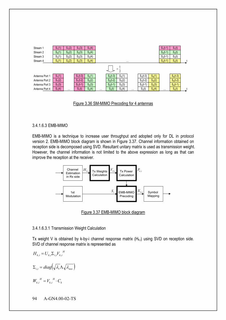
94 A-GN4.00-02-TS
Stream 1 S1(1) S1(2) S1(3) S1(4) S1(t-1) S1(t)Stream 2 S2(1) S2(2) S2(3) S2(4) S2(t-1) S2(t)Stream 3 S3(1) S3(2) S3(3) S3(4) S3(t-1) S3(t)Stream 4 S4(1) S4(2) S4(3) S4(4) S4(t-1) S4(t) t
Antenna Port 1 S1(1) S1(t-3) S2(1) S2(t-3) S3(1) S3(t-3) S4(1) S4(t-3)Antenna Port 2 S1(2) S1(t-2) S2(2) S2(t-2) S3(2) S3(t-2) S4(2) S4(t-2)Antenna Port 3 S1(3) S1(t-1) S2(3) S2(t-1) S3(3) S3(t-1) S4(3) S4(t-1)Antenna Port 4 S1(4) … S1(t) S2(4) … S2(t) S3(4) … S3(t) S4(4) … S4(t) t
…
21
×
Figure 3.36 SM-MIMO Precoding for 4 antennas
3.4.1.6.3 EMB-MIMO EMB-MIMO is a technique to increase user throughput and adopted only for DL in protocol version 2. EMB-MIMO block diagram is shown in Figure 3.37. Channel information obtained on reception side is decomposed using SVD. Resultant unitary matrix is used as transmission weight. However, the channel information is not limited to the above expression as long as that can improve the reception at the receiver.
Figure 3.37 EMB-MIMO block diagram
3.4.1.6.3.1 Transmission Weight Calculation Tx weight V is obtained by k-by-i channel response matrix (Hk,i) using SVD on reception side. SVD of channel response matrix is represented as
Hikiiikik VUH ,,,, Σ=
( )nosii diag λλ Λ=Σ 1,
kH
ikH
ik CVW ⋅= ,,
Tx Weights Calculation
Tx Power Calculation
Channel Estimation
Symbol Mapping
EMB-MIMO Precoding
1st Modulation
in Rx side
ikX ,iS
ikP ,ikV ,ikH ,
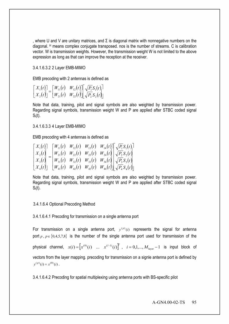
A-GN4.00-02-TS 95
, where U and V are unitary matrices, and Σ is diagonal matrix with nonnegative numbers on the diagonal. H means complex conjugate transposed. nos is the number of streams. C is calibration vector. W is transmission weights. However, the transmission weight W is not limited to the above expression as long as that can improve the reception at the receiver. 3.4.1.6.3.2 2 Layer EMB-MIMO EMB precoding with 2 antennas is defined as
( )( )
( ) ( )( ) ( )
( )( )
=
tSPtSP
tWtWtWtW
tXtX
22
11
2221
1211
2
1
Note that data, training, pilot and signal symbols are also weighted by transmission power. Regarding signal symbols, transmission weight W and P are applied after STBC coded signal Si(t). 3.4.1.6.3.3 4 Layer EMB-MIMO EMB precoding with 4 antennas is defined as
( )( )( )( )
( ) ( ) ( ) ( )( ) ( ) ( ) ( )( ) ( ) ( ) ( )( ) ( ) ( ) ( )
( )( )( )( )
=
tSPtSPtSPtSP
tWtWtWtWtWtWtWtWtWtWtWtWtWtWtWtW
tXtXtXtX
44
33
22
11
44434241
34333231
24232221
14131211
4
3
2
1
Note that data, training, pilot and signal symbols are also weighted by transmission power. Regarding signal symbols, transmission weight W and P are applied after STBC coded signal Si(t). 3.4.1.6.4 Optional Precoding Method 3.4.1.6.4.1 Precoding for transmission on a single antenna port For transmission on a single antenna port, )()( iy p represents the signal for antenna port p , { }8,7,5,4,0∈p is the number of the single antenna port used for transmission of the
physical channel, [ ]Tl ixixix )(...)()( )1()0( −= , 1,...,1,0 layer −= Mi is input block of
vectors from the layer mapping. precoding for transmission on a signle antenna port is defined by )()( )0()( ixiy p = .
3.4.1.6.4.2 Precoding for spatial multiplexing using antenna ports with BS-specific pilot
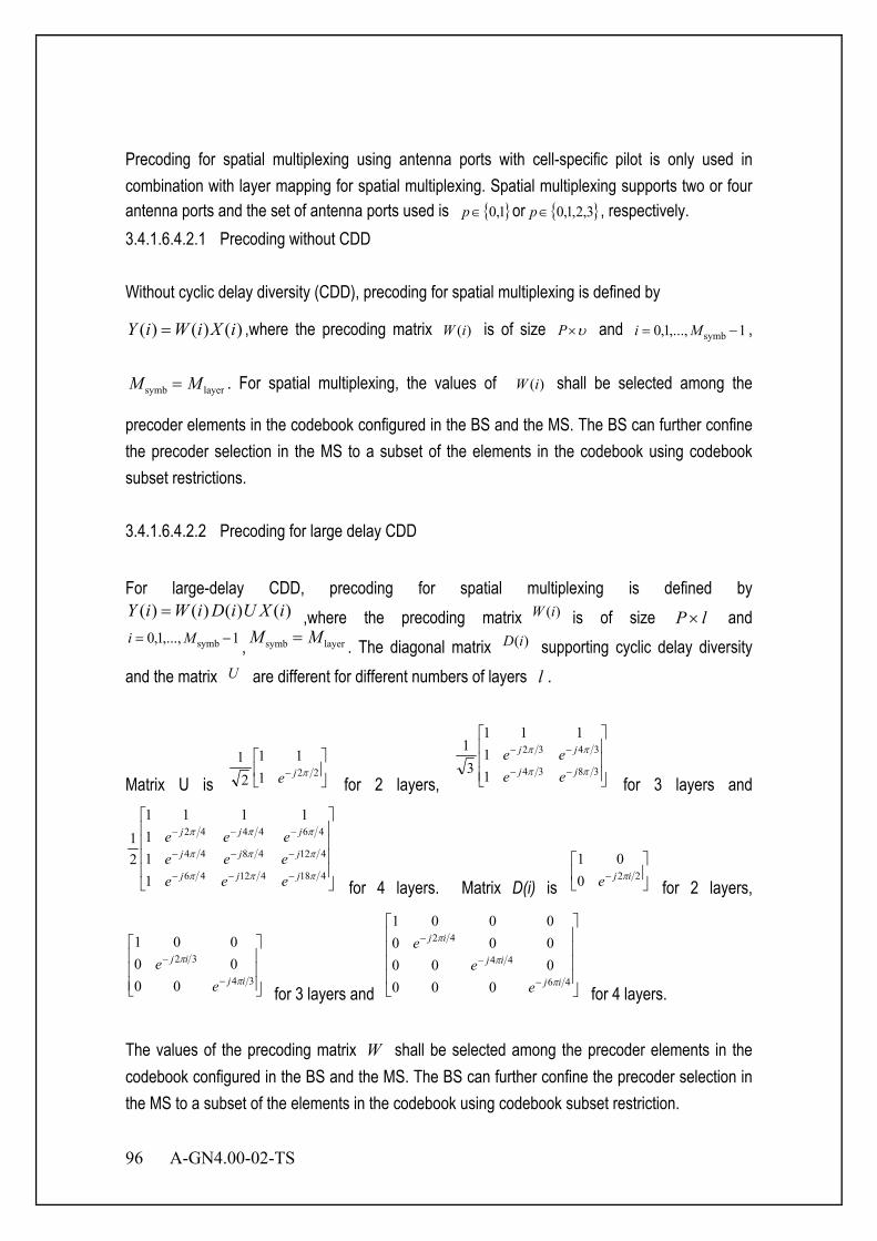
96 A-GN4.00-02-TS
Precoding for spatial multiplexing using antenna ports with cell-specific pilot is only used in combination with layer mapping for spatial multiplexing. Spatial multiplexing supports two or four antenna ports and the set of antenna ports used is { }1,0∈p or { }3,2,1,0∈p , respectively. 3.4.1.6.4.2.1 Precoding without CDD Without cyclic delay diversity (CDD), precoding for spatial multiplexing is defined by
)()()( iXiWiY = ,where the precoding matrix )(iW is of size υ×P and 1,...,1,0 symb −= Mi ,
layersymb MM = . For spatial multiplexing, the values of )(iW shall be selected among the
precoder elements in the codebook configured in the BS and the MS. The BS can further confine the precoder selection in the MS to a subset of the elements in the codebook using codebook subset restrictions. 3.4.1.6.4.2.2 Precoding for large delay CDD For large-delay CDD, precoding for spatial multiplexing is defined by
)()()()( iXUiDiWiY = ,where the precoding matrix )(iW is of size lP × and 1,...,1,0 symb −= Mi , layersymb MM = . The diagonal matrix )(iD supporting cyclic delay diversity
and the matrix U are different for different numbers of layers l .
Matrix U is
− 221
11
21
πje for 2 layers,
−−
−−
3834
3432
11
111
31
ππ
ππ
jj
jj
eeee
for 3 layers and
−−−
−−−
−−−
41841246
4124844
464442
111
1111
21
πππ
πππ
πππ
jjj
jjj
jjj
eeeeeeeee
for 4 layers. Matrix D(i) is
− 220
01ije π
for 2 layers,
−
−
34
32
0000001
ij
ij
ee
π
π
for 3 layers and
−
−
−
46
44
42
0000000000001
ij
ij
ij
ee
e
π
π
π
for 4 layers. The values of the precoding matrix W shall be selected among the precoder elements in the codebook configured in the BS and the MS. The BS can further confine the precoder selection in the MS to a subset of the elements in the codebook using codebook subset restriction.

A-GN4.00-02-TS 97
3.4.1.6.4.2.3 Codebook for precoding For transmission on two antenna ports, the precoding matrix W shall be selected
from
11
21
,
−11
21
,
j1
21
− j1
21
or a subset thereof for 1 layer. For 2 layers, the
precoding matrix )(iW shall be selected from
1001
21
,
−1111
21
,
− jj11
21
or a subset thereof . For the closed-loop spatial multiplexing transmission mode, the codebook index 0 is not used when the number layers is 2. For transmission on four antenna ports, the precoding matrix W shall be selected from a 16-matrix set or a subset thereof for different layer configuration. 3.4.1.6.4.3 Precoding for transmit diversity For 2 antennas transmit diversity,SFBC is adopted,and for 4 antennas transmit diversity,SFBC and FSTD are applied. if denotes the subcarrier index.
- 2 Layer SFBC-MIMO
Precoding for 2 Layer SFBC-MIMO with 2 antennas is defined as
( ) ( )( ) ( )
( ) ( )( ) ( )
−
=
2*
11*
2
2211
2212
2111
21
fSfSfSfS
fXfXfXfX , where * represents complex conjugate.
- 4 Layer SFBC-MIMO
Precoding for 4 Layer SFBC-MIMO with 4 antennas is defined as ( ) ( ) ( ) ( )( ) ( ) ( ) ( )( ) ( ) ( ) ( )( ) ( ) ( ) ( )
( ) ( )( ) ( )
( ) ( )( ) ( )
−−
=
4*
33*
4
2*
11*
2
4433
2211
44342414
43332313
42322212
41312111
0000
0000
21
fSfSfSfS
fSfSfSfS
fXfXfXfXfXfXfXfXfXfXfXfXfXfXfXfX
,
where * represents complex conjugate. 3.4.1.6.4.4 Precoding for spatial multiplexing using antenna ports with MS-specific pilot Precoding for spatial multiplexing using antenna ports with MS-specific pilot is only used in combination with layer mapping for spatial multiplexing. Spatial multiplexing using antenna ports with MS-specific pilot supports two antenna ports and the set of antenna ports used is { }8,7∈p . For transmission on two antenna ports, { }8,7∈p , the precoding operation is defined by
)()( )0()7( ixiy = and )()( )1()8( ixiy = .
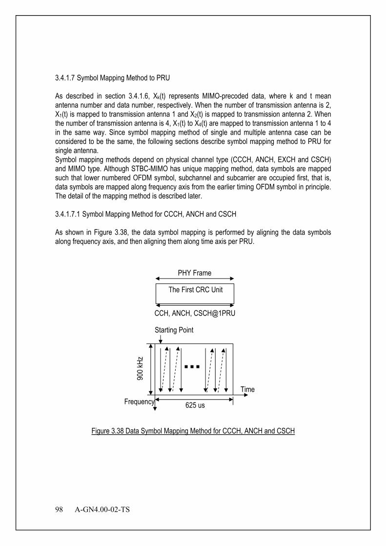
98 A-GN4.00-02-TS
3.4.1.7 Symbol Mapping Method to PRU As described in section 3.4.1.6, Xk(t) represents MIMO-precoded data, where k and t mean antenna number and data number, respectively. When the number of transmission antenna is 2, X1(t) is mapped to transmission antenna 1 and X2(t) is mapped to transmission antenna 2. When the number of transmission antenna is 4, X1(t) to X4(t) are mapped to transmission antenna 1 to 4 in the same way. Since symbol mapping method of single and multiple antenna case can be considered to be the same, the following sections describe symbol mapping method to PRU for single antenna. Symbol mapping methods depend on physical channel type (CCCH, ANCH, EXCH and CSCH) and MIMO type. Although STBC-MIMO has unique mapping method, data symbols are mapped such that lower numbered OFDM symbol, subchannel and subcarrier are occupied first, that is, data symbols are mapped along frequency axis from the earlier timing OFDM symbol in principle. The detail of the mapping method is described later. 3.4.1.7.1 Symbol Mapping Method for CCCH, ANCH and CSCH As shown in Figure 3.38, the data symbol mapping is performed by aligning the data symbols along frequency axis, and then aligning them along time axis per PRU.
TimeFrequency 625 us
900 k
Hz
Starting Point
CCH, ANCH, CSCH@1PRU
The First CRC Unit
PHY Frame
Figure 3.38 Data Symbol Mapping Method for CCCH, ANCH and CSCH
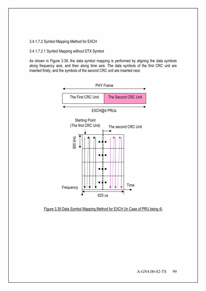
A-GN4.00-02-TS 99
3.4.1.7.2 Symbol Mapping Method for EXCH 3.4.1.7.2.1 Symbol Mapping without DTX Symbol As shown in Figure 3.39, the data symbol mapping is performed by aligning the data symbols along frequency axis, and then along time axis. The data symbols of the first CRC unit are inserted firstly, and the symbols of the second CRC unit are inserted next.
EXCH@4 PRUs
The First CRC Unit The Second CRC Unit
Time
625 us
900 k
Hz
Starting Point(The first CRC Unit)
Frequency
The second CRC Unit
PHY Frame
Figure 3.39 Data Symbol Mapping Method for EXCH (In Case of PRU being 4)
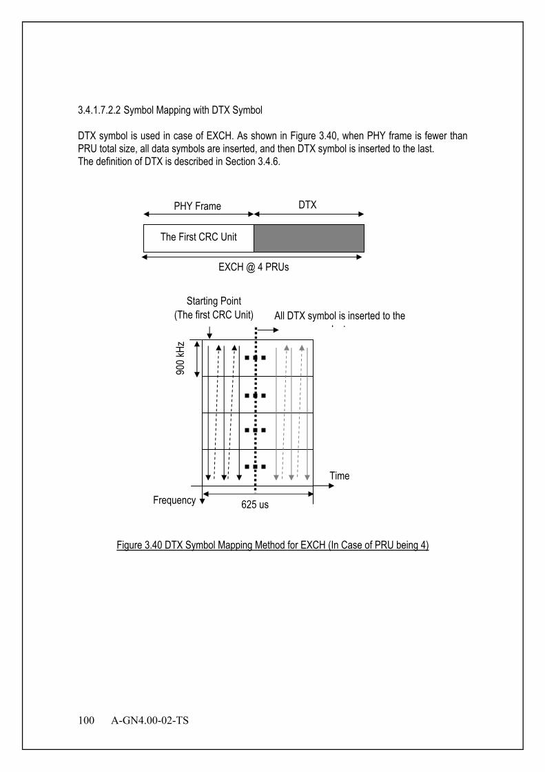
100 A-GN4.00-02-TS
3.4.1.7.2.2 Symbol Mapping with DTX Symbol DTX symbol is used in case of EXCH. As shown in Figure 3.40, when PHY frame is fewer than PRU total size, all data symbols are inserted, and then DTX symbol is inserted to the last. The definition of DTX is described in Section 3.4.6.
EXCH @ 4 PRUs
Time
625 us
900 k
Hz
Starting Point(The first CRC Unit)
Frequency
The First CRC Unit
DTX
All DTX symbol is inserted to thelast
PHY Frame
Figure 3.40 DTX Symbol Mapping Method for EXCH (In Case of PRU being 4)
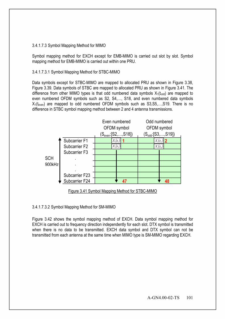
A-GN4.00-02-TS 101
3.4.1.7.3 Symbol Mapping Method for MIMO Symbol mapping method for EXCH except for EMB-MIMO is carried out slot by slot. Symbol mapping method for EMB-MIMO is carried out within one PRU. 3.4.1.7.3.1 Symbol Mapping Method for STBC-MIMO Data symbols except for STBC-MIMO are mapped to allocated PRU as shown in Figure 3.38, Figure 3.39. Data symbols of STBC are mapped to allocated PRU as shown in Figure 3.41. The difference from other MIMO types is that odd numbered data symbols X1(todd) are mapped to even numbered OFDM symbols such as S2, S4,…, S18, and even numbered data symbols X1(teven) are mapped to odd numbered OFDM symbols such as S3,S5,…,S19. There is no difference in STBC symbol mapping method between 2 and 4 antenna transmissions.
Subcarrier F1Subcarrier F2Subcarrier F3 . . .Subcarrier F23Subcarrier F24
Even numberedOFDM symbol
(Seven:[S2,…,S18])
Odd numberedOFDM symbol
(Sodd:[S3,…,S19])
SCH900kHz
( )11 tX ( )21 tX( )31 tX ( )41 tX
1 2
47 48
Figure 3.41 Symbol Mapping Method for STBC-MIMO
3.4.1.7.3.2 Symbol Mapping Method for SM-MIMO Figure 3.42 shows the symbol mapping method of EXCH. Data symbol mapping method for EXCH is carried out to frequency direction independently for each slot. DTX symbol is transmitted when there is no data to be transmitted. EXCH data symbol and DTX symbol can not be transmitted from each antenna at the same time when MIMO type is SM-MIMO regarding EXCH.
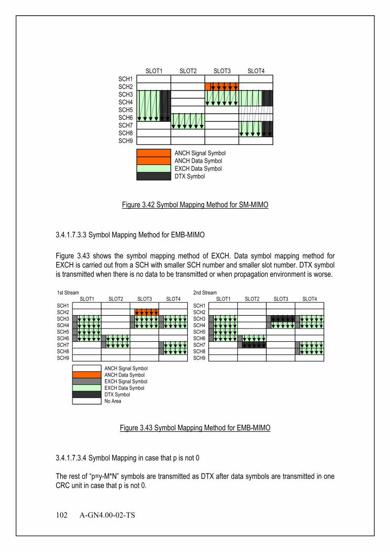
102 A-GN4.00-02-TS
SCH1SCH2SCH3SCH4SCH5SCH6SCH7SCH8SCH9
ANCH Signal SymbolANCH Data SymbolEXCH Data SymbolDTX Symbol
SLOT1 SLOT2 SLOT3 SLOT4
Figure 3.42 Symbol Mapping Method for SM-MIMO
3.4.1.7.3.3 Symbol Mapping Method for EMB-MIMO Figure 3.43 shows the symbol mapping method of EXCH. Data symbol mapping method for EXCH is carried out from a SCH with smaller SCH number and smaller slot number. DTX symbol is transmitted when there is no data to be transmitted or when propagation environment is worse. 1st Stream 2nd Stream
SCH1 SCH1SCH2 SCH2SCH3 SCH3SCH4 SCH4SCH5 SCH5SCH6 SCH6SCH7 SCH7SCH8 SCH8SCH9 SCH9
ANCH Signal SymbolANCH Data SymbolEXCH Signal SymbolEXCH Data SymbolDTX SymbolNo Area
SLOT1 SLOT2 SLOT3 SLOT4 SLOT1 SLOT2 SLOT3 SLOT4
Figure 3.43 Symbol Mapping Method for EMB-MIMO
3.4.1.7.3.4 Symbol Mapping in case that p is not 0 The rest of “p=y-M*N” symbols are transmitted as DTX after data symbols are transmitted in one CRC unit in case that p is not 0.

A-GN4.00-02-TS 103
F23 F22 F21 F20 F19 F18 F17 F16 F15 F14 F13 F12 F11 F10 F9 F8 F7 F6 F5 F4 F3 F2 F1
F24
S1 S2 S3 S4 S5 S6 S7 S8 S9 S10 S11 S12 S13 S14 S15 S16 S17 S18 S19
Data Symbol Guard Carrier DC Carrier Guard Time
Training Symbol(Antenna1) Training Symbol(Antenna2)
Pilot Symbol(Antenna1) Pilot Symbol(Antenna2)
“p=y-MN” data symbols are transmitted as DTX.
Figure 3.44 Symbol Mapping in case that p is not 0
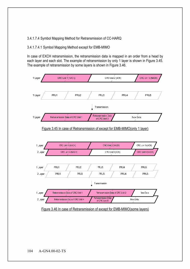
104 A-GN4.00-02-TS
3.4.1.7.4 Symbol Mapping Method for Retransmission of CC-HARQ 3.4.1.7.4.1 Symbol Mapping Method except for EMB-MIMO In case of EXCH retransmission, the retransmission data is mapped in an order from a head by each layer and each slot. The example of retransmission by only 1 layer is shown in Figure 3.45. The example of retransmission by some layers is shown in Figure 3.46.
Figure 3.45 In case of Retransmission of except for EMB-MIMO(only 1 layer)
Figure 3.46 In case of Retransmission of except for EMB-MIMO(some layers)
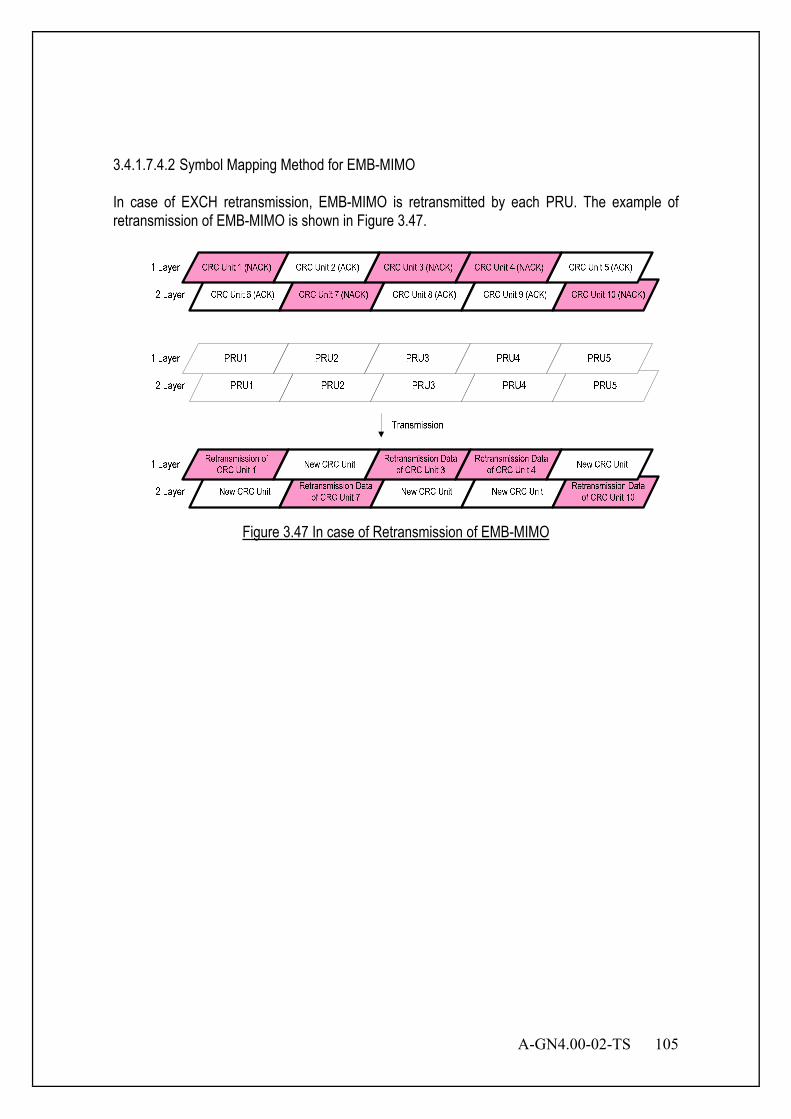
A-GN4.00-02-TS 105
3.4.1.7.4.2 Symbol Mapping Method for EMB-MIMO In case of EXCH retransmission, EMB-MIMO is retransmitted by each PRU. The example of retransmission of EMB-MIMO is shown in Figure 3.47.
Figure 3.47 In case of Retransmission of EMB-MIMO

106 A-GN4.00-02-TS
3.4.1.7.4.3 Symbol Mapping Method in case of full subcarrier mode It is necessary to consider full subcarrier mode except for EMB-MIMO. The retransmission CRC unit size is not necessarily the same as the PRU size in case of PRU allocation. (a) explains the case that the retransmission CRC unit size equals to the retransmission PRU size. (b) explains the case that the retransmission CRC unit size is smaller than the retransmission PRU size. (c) explains the case that the retransmission CRC unit size is larger than the retransmission PRU size.
(a) The case when Retransmission CRC Unit Size equals to Retransmission PRU Size Figure 3.48 and Figure 3.49 illustrate the case that retransmission CRC unit size equals to the retransmission PRU size. Figure 3.48 shows the case that retransmission data 2 and PRU size 2 equal to retransmission data 1 and PRU size 1. Figure 3.49 shows the case that retransmission data1 and PRU size 1 differ from retransmission data 2 and PRU size 2, when full subcarrier mode is used.
Retransmission Data 1 Retransmission Data 2 New Data
PRU 1 PRU 2 PRU 3
Retransimission CRC Unit
Retransmission Data 1 Retransmission Data 2 New Data
Transmission
New CRC Unit
Figure 3.48 The case when Retransmission CRC Unit Size equals to Retransmission PRU Size (1)
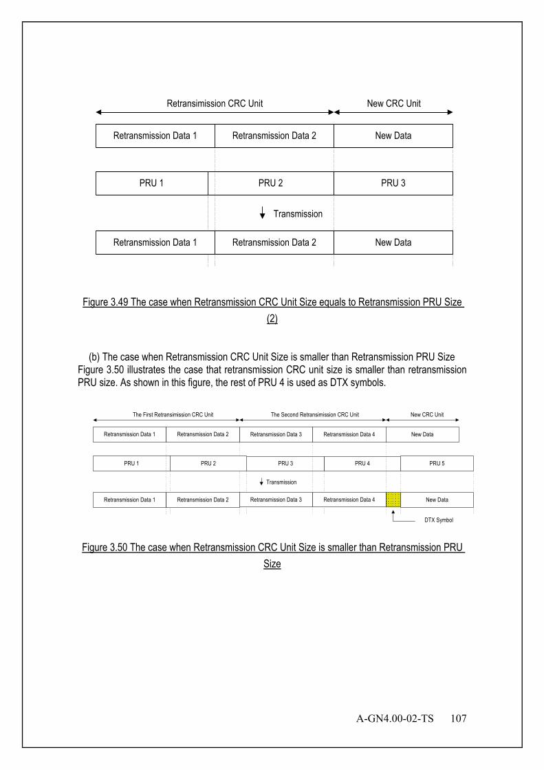
A-GN4.00-02-TS 107
Retransmission Data 1 Retransmission Data 2 New Data
PRU 1 PRU 2 PRU 3
Retransmission Data 1 Retransmission Data 2 New Data
Transmission
New CRC UnitRetransimission CRC Unit
Figure 3.49 The case when Retransmission CRC Unit Size equals to Retransmission PRU Size (2)
(b) The case when Retransmission CRC Unit Size is smaller than Retransmission PRU Size
Figure 3.50 illustrates the case that retransmission CRC unit size is smaller than retransmission PRU size. As shown in this figure, the rest of PRU 4 is used as DTX symbols.
Retransmission Data 3 Retransmission Data 4 New Data
PRU 3 PRU 4
The First Retransimission CRC Unit
Retransmission Data 1 Retransmission Data 2 New Data
Transmission
DTX Symbol
Retransmission Data 1 Retransmission Data 2
PRU 1
Retransmission Data 3 Retransmission Data 4
The Second Retransimission CRC Unit New CRC Unit
PRU 5PRU 2
Figure 3.50 The case when Retransmission CRC Unit Size is smaller than Retransmission PRU Size
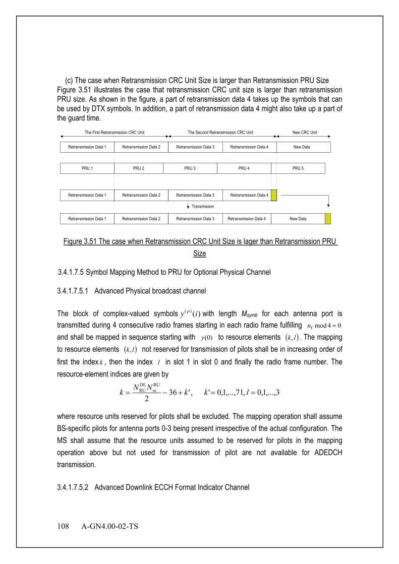
108 A-GN4.00-02-TS
(c) The case when Retransmission CRC Unit Size is larger than Retransmission PRU Size
Figure 3.51 illustrates the case that retransmission CRC unit size is larger than retransmission PRU size. As shown in the figure, a part of retransmission data 4 takes up the symbols that can be used by DTX symbols. In addition, a part of retransmission data 4 might also take up a part of the guard time.
Retransmission Data 1 Retransmission Data 2 New Data
PRU 1 PRU 2
Retransmission Data 1 Retransmission Data 2
Retransmission Data 1 Retransmission Data 2 New Data
Transmission
The First Retransimission CRC Unit
Retransmission Data 3 Retransmission Data 4
The Second Retransimission CRC Unit New CRC Unit
PRU 3 PRU 4 PRU 5
Retransmission Data 3 Retransmission Data 4
Retransmission Data 3 Retransmission Data 4
Figure 3.51 The case when Retransmission CRC Unit Size is lager than Retransmission PRU Size
3.4.1.7.5 Symbol Mapping Method to PRU for Optional Physical Channel 3.4.1.7.5.1 Advanced Physical broadcast channel The block of complex-valued symbols )()( iy p with length Msymb for each antenna port is transmitted during 4 consecutive radio frames starting in each radio frame fulfilling 04modf =n and shall be mapped in sequence starting with )0(y to resource elements ( )lk, . The mapping to resource elements ( )lk, not reserved for transmission of pilots shall be in increasing order of first the index k , then the index l in slot 1 in slot 0 and finally the radio frame number. The resource-element indices are given by
3,...,1,0,71,...,1,0' ,'362
RUsc
DLRU ==+−= lkkNNk
where resource units reserved for pilots shall be excluded. The mapping operation shall assume BS-specific pilots for antenna ports 0-3 being present irrespective of the actual configuration. The MS shall assume that the resource units assumed to be reserved for pilots in the mapping operation above but not used for transmission of pilot are not available for ADEDCH transmission. 3.4.1.7.5.2 Advanced Downlink ECCH Format Indicator Channel
A-GN4.00-02-TS 109
The mapping to resource units is defined in terms of quadruplets of complex-valued symbols. For each of the antenna ports, symbol quadruplets
)34(),24(),14(),4()( )()()()()( +++= iyiyiyiyiA ppppp shall be mapped in increasing order of i to
the four resource-point groups in the first OFDM symbol in a downlink slot with the representative resource-unit. )()( iA p is mapped to the resource-unit group represented by
2/2/ RUSC
DLRU NNikk ⋅⋅+= , where ( ) ( )DL
RUBSID
RUsc 2mod2 NNNk ⋅= and BS
IDN is the
physical-layer BS identity. 3.4.1.7.5.3 Advanced Downlink ECCH The mapping to resource units is defined by operations on quadruplets of complex-valued
symbols.The block of quadruplets )1(),...,0( quad)()( −MAA pp
shall be permuted resulting in
)1(),...,0( quad)()( −Mww pp
. The block of quadruplets )( pw shall be cyclically shifted, resulting in
)( pw , where 4symbquad MM = and )mod)(()( )()(quad
BSID
pp MNiwiw += .
Mapping of the block of quadruplets )( pw is defined in terms of resource-point groups, according to steps as shown in Figure 3.52:
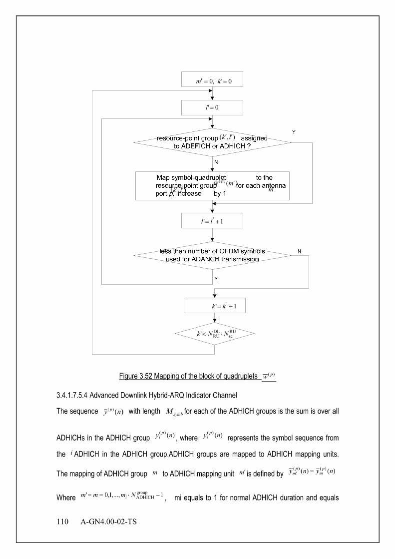
110 A-GN4.00-02-TS
,0=′m 0'=k
0'=l
),( lk ′′
)'()( mw p
),( lk ′′ m′
1' ' += ll
'l
1' ' += kk
RUsc
DLRU' NNk ⋅<
Figure 3.52 Mapping of the block of quadruplets )( pw
3.4.1.7.5.4 Advanced Downlink Hybrid-ARQ Indicator Channel
The sequence )()( ny p with length symbM for each of the ADHICH groups is the sum is over all
ADHICHs in the ADHICH group )()( ny pi , where )()( ny p
i represents the symbol sequence from
the i ADHICH in the ADHICH group.ADHICH groups are mapped to ADHICH mapping units.
The mapping of ADHICH group m to ADHICH mapping unit 'm is defined by )()(~ )()(' nyny p
mp
m =
Where 1,...,1,0' groupADHICH −⋅== Nmmm i , mi equals to 1 for normal ADHICH duration and equals
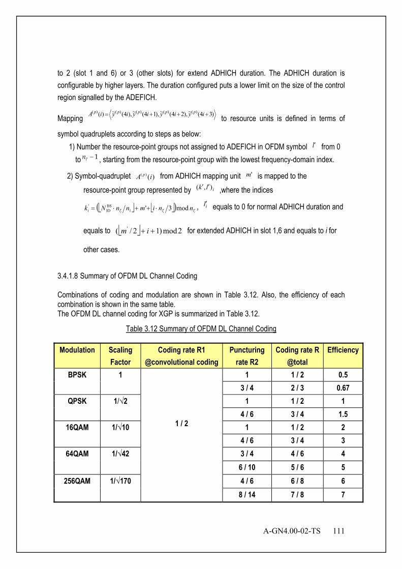
A-GN4.00-02-TS 111
to 2 (slot 1 and 6) or 3 (other slots) for extend ADHICH duration. The ADHICH duration is configurable by higher layers. The duration configured puts a lower limit on the size of the control region signalled by the ADEFICH.
Mapping )34(~),24(~),14(~),4(~)( )()()()()( +++= iyiyiyiyiA ppppp
to resource units is defined in terms of
symbol quadruplets according to steps as below: 1) Number the resource-point groups not assigned to ADEFICH in OFDM symbol l′ from 0
to 1ln ′ − , starting from the resource-point group with the lowest frequency-domain index.
2) Symbol-quadruplet )()( iA p from ADHICH mapping unit 'm is mapped to the resource-point group represented by ilk ),( ′′ ,where the indices
( )iii llli nnimnnNk ′′′ ⋅++⋅= mod3'1
BSID
' , il′ equals to 0 for normal ADHICH duration and
equals to 2mod)12/( ' ++ im for extended ADHICH in slot 1,6 and equals to i for
other cases.
3.4.1.8 Summary of OFDM DL Channel Coding Combinations of coding and modulation are shown in Table 3.12. Also, the efficiency of each combination is shown in the same table. The OFDM DL channel coding for XGP is summarized in Table 3.12.
Table 3.12 Summary of OFDM DL Channel Coding
Modulation Scaling Factor
Coding rate R1 @convolutional coding
Puncturing rate R2
Coding rate R @total
Efficiency
BPSK 1
1 / 2
1 1 / 2 0.5 3 / 4 2 / 3 0.67
QPSK 1/√2 1 1 / 2 1 4 / 6 3 / 4 1.5
16QAM 1/√10 1 1 / 2 2 4 / 6 3 / 4 3
64QAM 1/√42 3 / 4 4 / 6 4 6 / 10 5 / 6 5
256QAM 1/√170 4 / 6 6 / 8 6 8 / 14 7 / 8 7
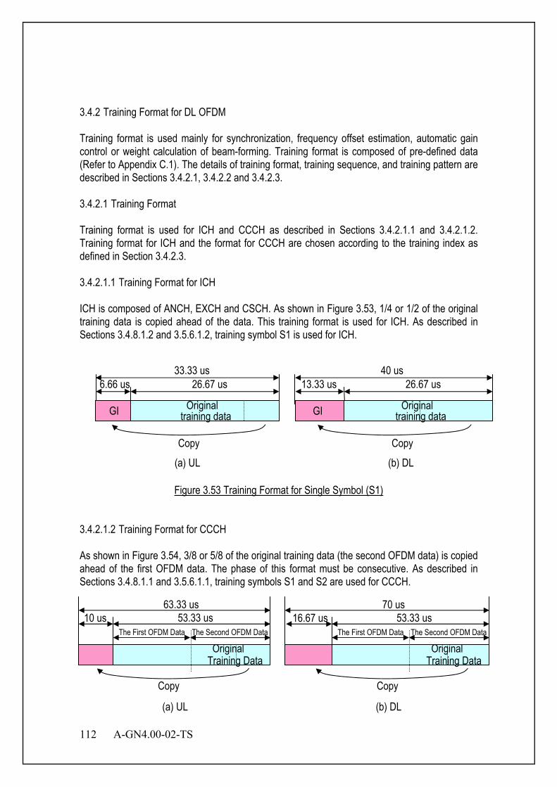
112 A-GN4.00-02-TS
3.4.2 Training Format for DL OFDM Training format is used mainly for synchronization, frequency offset estimation, automatic gain control or weight calculation of beam-forming. Training format is composed of pre-defined data (Refer to Appendix C.1). The details of training format, training sequence, and training pattern are described in Sections 3.4.2.1, 3.4.2.2 and 3.4.2.3. 3.4.2.1 Training Format Training format is used for ICH and CCCH as described in Sections 3.4.2.1.1 and 3.4.2.1.2. Training format for ICH and the format for CCCH are chosen according to the training index as defined in Section 3.4.2.3. 3.4.2.1.1 Training Format for ICH ICH is composed of ANCH, EXCH and CSCH. As shown in Figure 3.53, 1/4 or 1/2 of the original training data is copied ahead of the data. This training format is used for ICH. As described in Sections 3.4.8.1.2 and 3.5.6.1.2, training symbol S1 is used for ICH.
Figure 3.53 Training Format for Single Symbol (S1)
3.4.2.1.2 Training Format for CCCH As shown in Figure 3.54, 3/8 or 5/8 of the original training data (the second OFDM data) is copied ahead of the first OFDM data. The phase of this format must be consecutive. As described in Sections 3.4.8.1.1 and 3.5.6.1.1, training symbols S1 and S2 are used for CCCH.
6.66 us 26.67 us 33.33 us
GI
Copy
(a) UL
13.33 us 26.67 us 40 us
Copy
(b) DL
GI training data Original
training data Original
10 us 53.33 us
Copy
The Second OFDM Data The First OFDM Data
63.33 us
Original Training Data
16.67 us 53.33 us
Copy
The Second OFDM Data The First OFDM Data
70 us
(a) UL (b) DL
Original Training Data
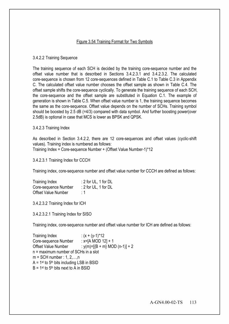
A-GN4.00-02-TS 113
Figure 3.54 Training Format for Two Symbols
3.4.2.2 Training Sequence The training sequence of each SCH is decided by the training core-sequence number and the offset value number that is described in Sections 3.4.2.3.1 and 3.4.2.3.2. The calculated core-sequence is chosen from 12 core-sequences defined in Table C.1 to Table C.3 in Appendix C. The calculated offset value number chooses the offset sample as shown in Table C.4. The offset sample shifts the core-sequence cyclically. To generate the training sequence of each SCH, the core-sequence and the offset sample are substituted in Equation C.1. The example of generation is shown in Table C.5. When offset value number is 1, the training sequence becomes the same as the core-sequence. Offset value depends on the number of SCHs. Training symbol should be boosted by 2.5 dB (=4/3) compared with data symbol. And further boosting power(over 2.5dB) is optional in case that MCS is lower as BPSK and QPSK. 3.4.2.3 Training Index As described in Section 3.4.2.2, there are 12 core-sequences and offset values (cyclic-shift values). Training index is numbered as follows: Training Index = Core-sequence Number + (Offset Value Number-1)*12 3.4.2.3.1 Training Index for CCCH Training index, core-sequence number and offset value number for CCCH are defined as follows: Training Index : 2 for UL, 1 for DL Core-sequence Number : 2 for UL, 1 for DL Offset Value Number : 1 3.4.2.3.2 Training Index for ICH 3.4.2.3.2.1 Training Index for SISO Training index, core-sequence number and offset value number for ICH are defined as follows: Training Index : (x + (y-1)*12 Core-sequence Number : x=[A MOD 12] + 1 Offset Value Number : y(m)=[{B + m} MOD (n-1)] + 2 n = maximum number of SCHs in a slot m = SCH number : 1, 2,…,n A = 1st to 5th bits including LSB in BSID B = 1st to 5th bits next to A in BSID
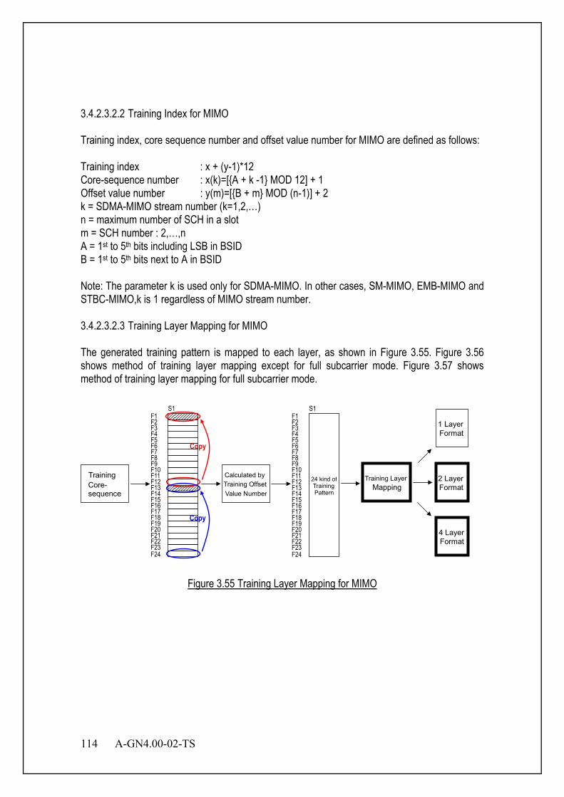
114 A-GN4.00-02-TS
3.4.2.3.2.2 Training Index for MIMO Training index, core sequence number and offset value number for MIMO are defined as follows: Training index : x + (y-1)*12 Core-sequence number : x(k)=[{A + k -1} MOD 12] + 1 Offset value number : y(m)=[{B + m} MOD (n-1)] + 2 k = SDMA-MIMO stream number (k=1,2,…) n = maximum number of SCH in a slot m = SCH number : 2,…,n A = 1st to 5th bits including LSB in BSID B = 1st to 5th bits next to A in BSID Note: The parameter k is used only for SDMA-MIMO. In other cases, SM-MIMO, EMB-MIMO and STBC-MIMO,k is 1 regardless of MIMO stream number. 3.4.2.3.2.3 Training Layer Mapping for MIMO The generated training pattern is mapped to each layer, as shown in Figure 3.55. Figure 3.56 shows method of training layer mapping except for full subcarrier mode. Figure 3.57 shows method of training layer mapping for full subcarrier mode.
Training Layer Mapping
Training Core- sequence
Calculated byTraining OffsetValue Number
4 Layer Format
2 Layer Format
1 Layer Format
F23 F22 F21 F20 F19 F18 F17 F16 F15 F14 F13 F12 F11 F10 F9 F8 F7 F6 F5 F4 F3 F2 F1
F24
Copy
Copy
S1
F24 F23 F22 F21 F20 F19 F18 F17 F16 F15 F14 F13 F12 F11 F10 F9 F8 F7 F6 F5 F4 F3 F2 F1
S1
24 kind ofTrainingPattern
Figure 3.55 Training Layer Mapping for MIMO

A-GN4.00-02-TS 115
F23 F22 F21 F20 F19 F18 F17 F16 F15 F14 F13 F12 F11 F10 F9 F8 F7 F6 F5 F4 F3 F2 F1
F24
Guard Carrier DC Carrier
Training Symbol(Antenna1) Training Symbol(Antenna2) Training Symbol(Antenna3) Training Symbol(Antenna4)
F23 F22 F21 F20 F19 F18 F17 F16 F15 F14 F13 F12 F11 F10 F9 F8 F7 F6 F5 F4 F3 F2 F1
F24
1 Layer Mapping 2 Layer Mapping 4 Layer Mapping
F23 F22 F21 F20 F19 F18 F17 F16 F15 F14 F13 F12 F11 F10 F9 F8 F7 F6 F5 F4 F3 F2 F1
F24
Figure 3.56 Training Layer Mapping for MIMO except for full subcarrier mode
F23 F22 F21 F20 F19 F18 F17 F16 F15 F14 F13 F12 F11 F10 F9 F8 F7 F6 F5 F4 F3 F2 F1
F24
Training Symbol(Antenna1) Training Symbol(Antenna2) Training Symbol(Antenna3) Training Symbol(Antenna4)
F23 F22 F21 F20 F19 F18 F17 F16 F15 F14 F13 F12 F11 F10 F9 F8 F7 F6 F5 F4 F3 F2 F1
F24
1 Layer Mapping 2 Layer Mapping 4 Layer Mapping
F23 F22 F21 F20 F19 F18 F17 F16 F15 F14 F13 F12 F11 F10 F9 F8 F7 F6 F5 F4 F3 F2 F1
F24

116 A-GN4.00-02-TS
Figure 3.57 Training Layer Mapping for MIMO for full subcarrier mode
3.4.2.4 Advanced Synchronization Signal 3.4.2.4.1 Advanced primary synchronization signal 3.4.2.4.1.1 Sequence generation The sequence )(nd used for the advanced primary synchronization signal is generated from a frequency-domain Zadoff-Chu sequence according to
=
== ++−
+−
61,...,32,31
30,...,1,0)(63
)2)(1(
63)1(
ne
nend nnuj
nunj
u π
π
where the Zadoff-Chu root sequence index u is 25, 29 and 34 for NID =0,1,2 repectively. 3.4.2.4.1.2 Mapping to resource units The mapping of the sequence to resource units depends on the frame structure. The MS shall not assume that the advanced primary synchronization signal is transmitted on the same antenna port as any of the downlink pilots. The MS shall not assume that any transmission instance of the advanced primary synchronization signal is transmitted on the same antenna port, or ports used for any other transmission instance of the advanced primary synchronization signal. The sequence ( )nd shall be mapped to the resource elements according to
( )2
31,61,...,0 ,RUsc
DLRU
,NNnknnda lk +−===
The advanced primary synchronization signal shall be mapped to the third OFDM symbol in slots 1 and 6. Resource elements ),( lk in the OFDM symbols used for transmission of the advanced primary synchronization signal where
66,...63,62,1,...,4,5,2
31RUsc
DLRU −−−=+−= nNNnk
are reserved and not used for transmission of the advanced primary synchronization signal. 3.4.2.4.2 Advanced secondary synchronization signal 3.4.2.4.2.1 Sequence generation The sequence )61(),...,0( dd used for the advanced second synchronization signal is an interleaved concatenation of two length-31 binary sequences. The concatenated sequence is
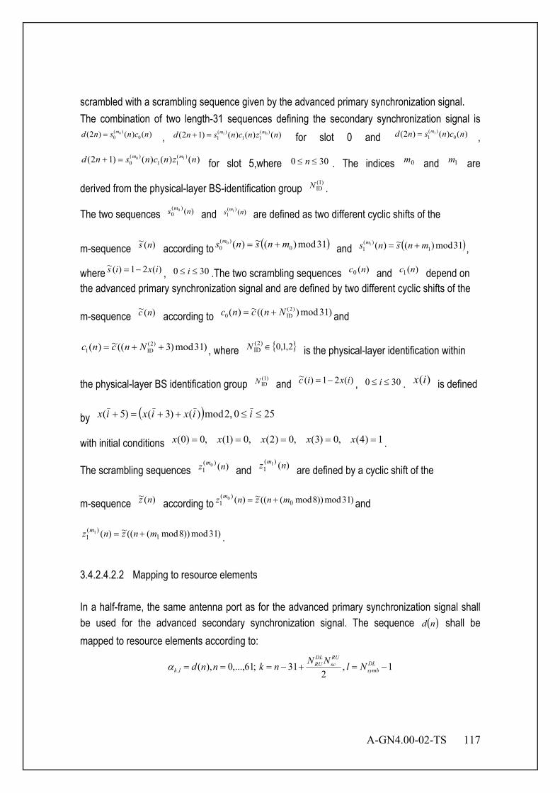
A-GN4.00-02-TS 117
scrambled with a scrambling sequence given by the advanced primary synchronization signal. The combination of two length-31 sequences defining the secondary synchronization signal is
)()()2( 0)(
00 ncnsnd m= , )()()()12( )(
11)(
101 nzncnsnd mm=+ for slot 0 and )()()2( 0
)(1
1 ncnsnd m= ,
)()()()12( )(11
)(0
10 nzncnsnd mm=+ for slot 5,where 300 ≤≤ n . The indices 0m and 1m are
derived from the physical-layer BS-identification group (1)IDN .
The two sequences )()(0
0 ns m and )()(
11 ns m are defined as two different cyclic shifts of the
m-sequence )(~ ns according to ( )31mod)(~)( 0)(
00 mnsns m += and ( )31mod)(~)( 1
)(1
1 mnsns m += ,
where )(21)(~ ixis −= , 300 ≤≤ i .The two scrambling sequences )(0 nc and )(1 nc depend on the advanced primary synchronization signal and are defined by two different cyclic shifts of the
m-sequence )(~ nc according to )31mod)((~)( )2(ID0 Nncnc += and
)31mod)3((~)( )2(ID1 ++= Nncnc , where { }2,1,0)2(
ID ∈N is the physical-layer identification within
the physical-layer BS identification group (1)IDN and )(21)(~ ixic −= , 300 ≤≤ i . )(ix is defined
by ( ) 250 ,2mod)()3()5( ≤≤++=+ iixixix
with initial conditions 1)4(,0)3(,0)2(,0)1(,0)0( ===== xxxxx .
The scrambling sequences )()(1
0 nz m and )()(
11 nz m
are defined by a cyclic shift of the
m-sequence )(~ nz according to )31mod))8mod(((~)( 0)(
10 mnznz m += and
)31mod))8mod(((~)( 1)(
11 mnznz m += .
3.4.2.4.2.2 Mapping to resource elements In a half-frame, the same antenna port as for the advanced primary synchronization signal shall be used for the advanced secondary synchronization signal. The sequence ( )nd shall be mapped to resource elements according to:
1,2
31;61,...,0),(, −=+−=== DLsymb
RUsc
DLRU
lk NlNNnknndα
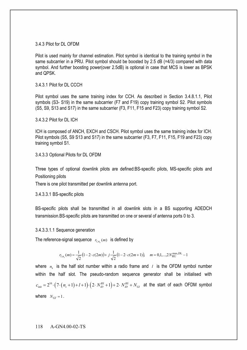
118 A-GN4.00-02-TS
3.4.3 Pilot for DL OFDM Pilot is used mainly for channel estimation. Pilot symbol is identical to the training symbol in the same subcarrier in a PRU. Pilot symbol should be boosted by 2.5 dB (=4/3) compared with data symbol. And further boosting power(over 2.5dB) is optional in case that MCS is lower as BPSK and QPSK. 3.4.3.1 Pilot for DL CCCH Pilot symbol uses the same training index for CCH. As described in Section 3.4.8.1.1, Pilot symbols (S3- S19) in the same subcarrier (F7 and F19) copy training symbol S2. Pilot symbols (S5, S9, S13 and S17) in the same subcarrier (F3, F11, F15 and F23) copy training symbol S2. 3.4.3.2 Pilot for DL ICH ICH is composed of ANCH, EXCH and CSCH. Pilot symbol uses the same training index for ICH. Pilot symbols (S5, S9 S13 and S17) in the same subcarrier (F3, F7, F11, F15, F19 and F23) copy training symbol S1. 3.4.3.3 Optional Pilots for DL OFDM Three types of optional downlink pilots are defined:BS-specific pilots, MS-specific pilots and Positioning pilots There is one pilot transmitted per downlink antenna port.
3.4.3.3.1 BS-specific pilots BS-specific pilots shall be transmitted in all downlink slots in a BS supporting ADEDCH transmission.BS-specific pilots are transmitted on one or several of antenna ports 0 to 3. 3.4.3.3.1.1 Sequence generation
The reference-signal sequence )(s, mr nl is defined by
( ) ( ) 12,...,1,0 ,)12(212
1)2(212
1)( DLmax,RU, s
−=+⋅−+⋅−= Nmmcjmcmr nl
where sn is the half slot number within a radio frame and l is the OFDM symbol number within the half slot. The pseudo-random sequence generator shall be initialised with
( )( ) ( )10init 2 7 1 1 2 1 2BS BS
s ID ID GIc n l N N N= ⋅ ⋅ + + + ⋅ ⋅ + + ⋅ + at the start of each OFDM symbol
where 1=GIN .

A-GN4.00-02-TS 119
3.4.3.3.1.2 Mapping to resource elements
The pilot sequence )(s, mr nl shall be mapped to complex-valued modulation symbols )(
,plka
used as reference symbols for antenna port p in half slot sn according to )'(s,
)(, mra nlplk = ,
where ( ) 6mod6 shiftvvmk ++= , 12,...,1,0 DLRU −⋅= Nm , DL
RUDLmax,
RU NNmm −+=′ and
{ }{ }
∈∈−
=3,2 if11,0 if3,0 DL
symb
ppN
l .
The variables v and shiftv define the position in the frequency domain for the different pilots where v is given by 0=v 0 and 0 if == lp and 0 and 1 if ≠= lp ,
3=v 0 and 0 if ≠= lp and 0 and 1 if == lp , )2mod(3 snv = 2 if =p , )2mod(33 snv += 3 if =p .The BS-specific frequency shift is given by BS
shift ID mod 6v N= . Resource units ( )lk , used for pilot transmission on any of the antenna ports in a half slot shall not be used for any transmission on any other antenna port in the same half slot and set to zero. 3.4.3.3.2 MS-specific pilots MS-specific pilots are supported for single-antenna-port transmission of ADEDCH and are transmitted on antenna port 5, 7, or 8. MS-specific pilots are also supported for spatial multiplexing on antenna ports 7 and 8. MS specific pilots are present and are a valid reference for ADEDCH demodulation only if the ADEDCH transmission is associated with the corresponding antenna port. MS-specific pilots are transmitted only on the resource units upon which the corresponding ADEDCH is mapped. The MS-specific pilot is not transmitted in resource elements ( )lk , in which one of the physical channels or physical signals other than MS-specific pilot defined in 6.1 are transmitted using resource elements with the same index pair ( )lk , regardless of their antenna port p . 3.4.3.3.2.1 Sequence generation
For antenna port 5, the MS-specific reference-signal sequence )(s
mrn is defined by
( ) ( ) 11210 ,)12(212
1)2(212
1)( ADEDCHRUs
−=+⋅−+⋅−= N,...,,mmcjmcmrn
where ADEDCHRUN denotes the bandwidth in resource units of the corresponding ADEDCH
transmission. The pseudo-random sequence generator shall be initialised with ( ) ( ) MSID
BSIDsinit nNnC +⋅+⋅+= 1621212/ at the start of each slot.

120 A-GN4.00-02-TS
For antenna ports 7 and 8, the reference-signal sequence )(mr is defined by
( ) ( ) 11210 ,)12(212
1)2(212
1)( DLmax,RU −=+⋅−+⋅−= N,...,,mmcjmcmr .
The pseudo-random sequence generator shall be initialised with
( ) ( )BS 16init ID SCID/ 2 1 2 1 2sc n N n= + ⋅ + ⋅ + at the start of each slot, where SCIDn is 0 or 1
according to the most recent ADECI format 2B associated with the ADEDCH transmission. If there is no ADECI format 2B associated with the ADEDCH transmission, the MS shall assume that SCIDn is zero. 3.4.3.3.2.2 Mapping to resource elements
For antenna port 5, in a physical resource unit with frequency-domain index UnPR assigned for
the corresponding ADEDCH transmission, the pilot sequence )(s
mrn shall be mapped to
complex-valued modulation symbols with 5=p in a slot according
to )'3( ADEDCHRU
)(, s
mNlra nplk +⋅′⋅= ,where PRU
RUsc
RUscmod)( nNNkk ⋅+′= , ,
{ }{ }
∈++∈+
=′6,5 if4mod)2(4m'3,2 if'4
shift
shift
lvlvm
k,
==
=′12mod if2,302mod if1,0
s
s
nn
l and 5,2,6,3=l for 3,2,1,0' =l
respectively. 13,...,1,0' ADEDCHRU −= Nm is the counter of MS-specific pilot resource elements within
a respective OFDM symbol of the ADEDCH transmission.The BS-specific frequency shift is given by BS
shift ID mod3v N= . The mapping shall be in increasing order of the frequency-domain index
UnPR of the physical resource units assigned for the corresponding ADEDCH transmission. The
quantity ADEDCHRUN denotes the bandwidth in resource units of the corresponding ADEDCH
transmission.
The notation pR is used to denote a resource unit used for pilot transmission on antenna
port p .For antenna ports 7 and 8, in a physical resource unit with frequency-domain index UnPR
assigned for the corresponding ADEDCH transmission, a part of the pilot sequence )(mr shall
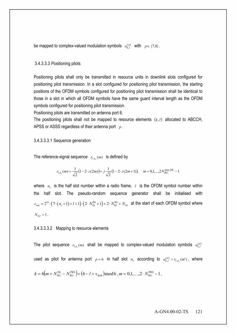
A-GN4.00-02-TS 121
be mapped to complex-valued modulation symbols )(,plka with }8,7{∈p .
3.4.3.3.3 Positioning pilots Positioning pilots shall only be transmitted in resource units in downlink slots configured for positioning pilot transmission. In a slot configured for positioning pilot transmission, the starting positions of the OFDM symbols configured for positioning pilot transmission shall be identical to those in a slot in which all OFDM symbols have the same guard interval length as the OFDM symbols configured for positioning pilot transmission. Positioning pilots are transmitted on antenna port 6. The positioning pilots shall not be mapped to resource elements ( )lk , allocated to ABCCH, APSS or ASSS regardless of their antenna port p . 3.4.3.3.3.1 Sequence generation
The reference-signal sequence )(s, mr nl is defined by
( ) ( ) 12,...,1,0 ,)12(212
1)2(212
1)( DLmax,RU, s
−=+⋅−+⋅−= Nmmcjmcmr nl
where sn is the half slot number within a radio frame, l is the OFDM symbol number within the half slot. The pseudo-random sequence generator shall be initialised with
( )( ) ( )10 BS BSinit s ID ID GI2 7 1 1 2 1 2c n l N N N= ⋅ ⋅ + + + ⋅ ⋅ + + ⋅ + at the start of each OFDM symbol where
1=GIN .
3.4.3.3.3.2 Mapping to resource elements
The pilot sequence )(s, mr nl shall be mapped to complex-valued modulation symbols )(
,plka
used as pilot for antenna port 6=p in half slot sn according to )'(s,
)(, mra nlplk = , where
( ) ( ) 6mod66 shiftPRSRU
DLRU vlNNmk +−+−+= , 12,,1,0 PRS
RU −⋅= Nm K ,

122 A-GN4.00-02-TS
PRSRU
DLmax,RU NNmm −+=′ and ( )
( )
===
=portsantennaBCCH4and12modif6,5,3,2
portsantennaABCCH2or1and12modif6,5,3,2,102modif6,5,3
s
s
s
Annn
l .
The bandwidth for positioning pilots and PRSRUN is configured by higher layers and the
BS-specific frequency shift is given by IDshift BS mod 6v N= .
3.4.3.3.3.3 Positioning pilot slot configuration The PRS configuration index PRSI is configured by higher layers. The BS specific slot configuration period PRST and the BS specific slot offset PRS∆ for the transmission of positioning pilots is determined by PRSI . If PRSI is from 1 to 159, PRST is 160 and PRSI=∆PRS . If PRSI is from 160 to 479, PRST is 320 and 160PRS −=∆ PRSI . If PRSI is from 480 to 1119,
PRST is 640 and 480PRS −=∆ PRSI . If PRSI is from 1120 to 2399, PRST is 1280 and 1120PRS −=∆ PRSI . Positioning pilots are transmitted only in configured DL slots. Positioning
pilots shall not be transmitted in special slots. Positioning pilots shall be transmitted in PRSN consecutive downlink slots, where PRSN is configured by higher layers. The positioning pilot instances, for the first slot of the PRSN downlink slots, shall satisfy
( ) 0mod2/10 PRSPRSsf =∆−+× Tnn . 3.4.4 Training and Pilot Boosting Boosting of training and pilot symbol should be defined to improve accuracy of channel estimation as with protocol version 1. Transmission power should be always constant even if MIMO is applied. Training and pilot boosting should change the boosting value of each layer because "Total power of total antenna in one PRU" is the same as "Total power of single antenna in one PRU". The power of the training and pilot symbol should equate in any case including MIMO in consideration of the carrier sense. These boosting values defined in this section should be default. 3.4.4.1 1 Layer Format SISO/SDMA Figure 3.58 shows training and pilot boosting for 1 layer format. In this case, training and pilot symbols are 2.5dB higher than data symbols as default.

A-GN4.00-02-TS 123
F23 F22 F21 F20 F19 F18 F17 F16 F15 F14 F13 F12 F11 F10 F9 F8 F7 F6 F5 F4 F3 F2 F1
F24
S1 S2 S3 S4 S5 S6 S7 S8 S9 S10 S11 S12 S13 S14 S15 S16 S17 S18 S19
Antenna1 Data Symbol DC Carrier Guard Carrier
2.5dB Up
S1
f
2.5dB Up
S5
f
2.5dB Up
Time
Tx Power
Total Power
Figure 3.58 Training and Pilot boosting for 1 Layer format
3.4.4.2 2 Layer MIMO Format except for SDMA Figure 3.59 shows training and pilot boosting for 2 layer format. In this case, training and pilot symbols are 5.5dB higher than data symbols because data symbols are multiplexed, but training and pilot are skipped with regular intervals.
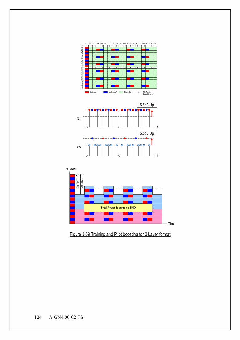
124 A-GN4.00-02-TS
F23 F22 F21 F20 F19 F18 F17 F16 F15 F14 F13 F12 F11 F10 F9 F8 F7 F6 F5 F4 F3 F2 F1
F24
S1 S2 S3 S4 S5 S6 S7 S8 S9 S10 S11 S12 S13 S14 S15 S16 S17 S18 S19
Antenna1 Data Symbol Antenna2 DC Carrier Guard Carrier
5.5dB Up
S1
f
S5
f
5.5dB Up
2.5dB Up
Time
Tx Power
Total Power is same as SISO
5.5dB Up
Figure 3.59 Training and Pilot boosting for 2 Layer format
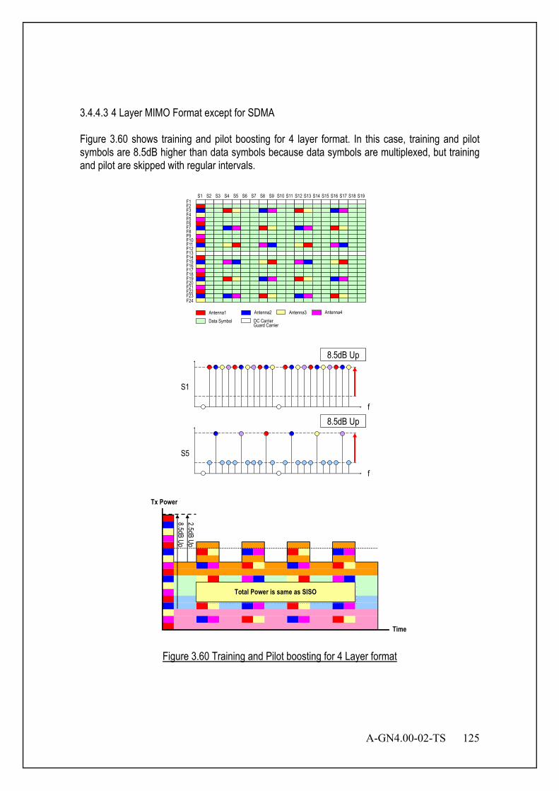
A-GN4.00-02-TS 125
3.4.4.3 4 Layer MIMO Format except for SDMA Figure 3.60 shows training and pilot boosting for 4 layer format. In this case, training and pilot symbols are 8.5dB higher than data symbols because data symbols are multiplexed, but training and pilot are skipped with regular intervals.
F23 F22 F21 F20 F19 F18 F17 F16 F15 F14 F13 F12 F11 F10 F9 F8 F7 F6 F5 F4 F3 F2 F1
F24
S1 S2 S3 S4 S5 S6 S7 S8 S9 S10 S11 S12 S13 S14 S15 S16 S17 S18 S19
Antenna1 Data Symbol
Antenna2 DC Carrier Guard Carrier
Antenna3 Antenna4
8.5dB Up
S1
f
S5
f
8.5dB Up
2.5dB Up
Time
Tx Power
Total Power is same as SISO
8.5dB Up
Figure 3.60 Training and Pilot boosting for 4 Layer format

126 A-GN4.00-02-TS
3.4.4.4 Summary for Training and Pilot Boosting The amount of training and pilot boosting depends on the MIMO type. Table 3.13 summarizes the relation between MIMO type and training and pilot boosting.
Table 3.13 Summary for Training and Pilot Boosting (Default)
1 Layer Format 2 Layer Format 4 Layer Format SISO/SDMA 2.5dB - -
STBC - 5.5dB SM/EMB - 5.5dB 8.5dB
3.4.4.5 Optional Downlink Pilot boosting The BS determines the downlink transmit energy per resource element. A MS may assume downlink BS-specific RS EPRP is constant across the downlink system bandwidth and constant across all slots until different BS-specific RS power information is received. The downlink reference-signal transmit power is defined as the linear average over the power contributions (in [W]) of all resource elements that carry BS-specific pilots within the operating system bandwidth. The ratio of ADEDCH EPRP to BS-specific RS EPRP among ADEDCH REs for each OFDM symbol is denoted by either Aρ or Bρ according to the OFDM symbol index. Aρ and Bρ are MS-specific. If the number of antenna ports is 1 or 2, Aρ is from {1,2,3,5,6} and Bρ is 0 or 4. If the number of antenna ports is 4, Aρ is from {2,3,5,6} and Bρ is from {0,1,4}. 3.4.5 Signal for DL OFDM Figure 3.61 describes the channel coding block diagram for DL signal symbol.
Figure 3.61 Signal Block Diagram
3.4.5.1 Encoding and Small Scrambling Error correction code method is defined as hamming coding.
Encoding Modulation Signal Data(bit) Coded Signal Data(symbol)
Small Scrambling
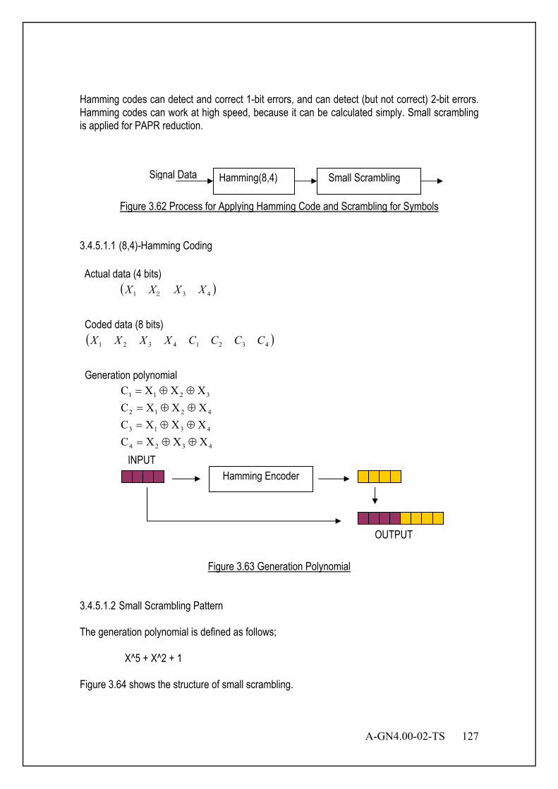
A-GN4.00-02-TS 127
Hamming codes can detect and correct 1-bit errors, and can detect (but not correct) 2-bit errors. Hamming codes can work at high speed, because it can be calculated simply. Small scrambling is applied for PAPR reduction.
Figure 3.62 Process for Applying Hamming Code and Scrambling for Symbols
3.4.5.1.1 (8,4)-Hamming Coding Actual data (4 bits)
( )431 XXXX 2 Coded data (8 bits) ( )43214321 CCCCXXXX Generation polynomial
4324
4313
4212
3211
XXXCXXXCXXXCXXXC
⊕⊕=⊕⊕=⊕⊕=⊕⊕=
Figure 3.63 Generation Polynomial
3.4.5.1.2 Small Scrambling Pattern The generation polynomial is defined as follows;
X^5 + X^2 + 1
Figure 3.64 shows the structure of small scrambling.
Hamming Encoder INPUT
OUTPUT
Hamming(8,4) Signal Data Small Scrambling
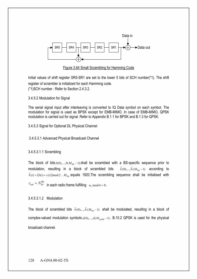
128 A-GN4.00-02-TS
SR5 SR4 SR3 SR2 SR1
Data in
Data out
Figure 3.64 Small Scrambling for Hamming Code
Initial values of shift register SR5-SR1 are set to the lower 5 bits of SCH number(*1). The shift register of scrambler is initialized for each Hamming code. (*1)SCH number : Refer to Section 2.4.3.2. 3.4.5.2 Modulation for Signal The serial signal input after interleaving is converted to IQ Data symbol on each symbol. The modulation for signal is used as BPSK except for EMB-MIMO. In case of EMB-MIMO, QPSK modulation is carried out for signal. Refer to Appendix B.1.1 for BPSK and B.1.3 for QPSK. 3.4.5.3 Signal for Optional DL Physical Channel
3.4.5.3.1 Advanced Physical Broadcast Channel
3.4.5.3.1.1 Scrambling The block of bits )1(),...,0( bit −Mbb shall be scrambled with a BS-specific sequence prior to modulation, resulting in a block of scrambled bits )1(
~),...,0(
~bit −Mbb according to
( ) 2mod)()()(~
icibib += . bitM equals 1920,The scrambling sequence shall be initialised with BS
init IDc N= in each radio frame fulfilling 04modf =n .
3.4.5.3.1.2 Modulation The block of scrambled bits )1(
~),...,0(
~bit −Mbb shall be modulated, resulting in a block of
complex-valued modulation symbols )1(),...,0( symb −Mdd . B.10.2 QPSK is used for the physical
broadcast channel.

A-GN4.00-02-TS 129
3.4.5.3.1.3 Layer mapping and precoding
The block of modulation symbols )1(),...,0( symb −Mdd shall be mapped to layers with
symb)0(
symb MM = and precoded, resulting in a block of vectors [ ]TP iyiyiy )(...)()( )1()0( −= ,
1,...,0 symb −= Mi , where )()( iy p represents the signal for antenna port p and where
1,...,0 −= Pp and the number of antenna ports for BS-specific pilots { }4,2,1∈P . 3.4.5.3.2 Advanced Downlink ECCH Indicator Channel The ADEFICH shall be transmitted when the number of OFDM symbols for ADECCH is greater than zero. 1 or 2 OFDM symbols are used for ADECCH in slot 1 and 6,. 1,2 or 3 OFDM symbols are used for ADECCH in slots (except slot 6) configured with Positioning pilots, 3.4.5.3.2.1 Scrambling The block of bits )31(),...,0( bb transmitted in one slot shall be scrambled with a BS-specific sequence prior to modulation, resulting in a block of scrambled bits )31(
~),...,0(
~bb according
to ( ) 2mod)()()(~
icibib += . The scrambling sequence generator shall be initialised with
( ) ( )BS 9 BSinit s ID ID2 1 2 1 2c n N N= + ⋅ + ⋅ + at the start of each slot.
3.4.5.3.2.2 Modulation The block of scrambled bits )31(
~),...,0(
~bb shall be modulated, resulting in a block of
complex-valued modulation symbols )15(),...,0( dd . QPSK is used for the ADEFICH. 3.4.5.3.2.3 Layer mapping and precoding
The block of modulation symbols )15(),...,0( dd shall be mapped to layers with 16)0(symb =M and
precoded, resulting in a block of vectors [ ]TP iyiyiy )(...)()( )1()0( −= , 15,...,0=i , where
)()( iy p represents the signal for antenna port p and where 1,...,0 −= Pp and the number of antenna ports for BS-specific pilots { }4,2,1∈P . The ADEFICH shall be transmitted on the same
130 A-GN4.00-02-TS
set of antenna ports as the ABCCH. 3.4.5.3.3 Advanced Downlink ECCH 3.4.5.3.3.1 ADECCH formats An ADECCH is transmitted on an aggregation of one or several consecutive RP(Resource Point) groups. The number of resource-point groups not assigned to ADEFICH or ADHICH is RPGN .
The cluster of RP groups available in the system are numbered from 0 and 1−−RPGCN , where
9/RPGRPGC NN =− . An ADECCH consisting of n consecutive RPGs may only start on a RPG
fulfilling 0mod =ni , where i is the RPG number. Multiple ADECCHs can be transmitted in a slot.
RPGCN − is 1,3,4,8, RPGN is 9,18,36,72 and Number of ADECCH bits is 72,144,288,576 for
ADECCH format 0,1,2,3 respectively. 3.4.5.3.3.2 ADECCH multiplexing and scrambling
The block of bits )1(),...,0( (i)bit
)()( −Mbb ii on each of the control channels to be transmitted in a
slot, where (i)bitM is the number of bits in one slot to be transmitted on ADECCH number i ,
shall be multiplexed, resulting in a block of bits
ADECCH ADECCH ADECCH( 1) ( 1) ( -1)(0) (0) (0) (1) (1) (1)bit bit bit(0),..., ( 1), (0),..., ( 1),..., (0),..., ( 1)n n nb b M b b M b b M− −− − − ,where ADECCHn
is the number of ADECCHs transmitted in the slot. The block of bits
ADECCH ADECCH ADECCH( 1) ( 1) ( -1)(0) (0) (0) (1) (1) (1)bit bit bit(0),..., ( 1), (0),..., ( 1),..., (0),..., ( 1)n n nb b M b b M b b M− −− − − shall be
scrambled with a BS-specific sequence prior to modulation, resulting in a block of scrambled bits
)1(~
),...,0(~
tot −Mbb according to ( ) 2mod)()()(~
icibib += .
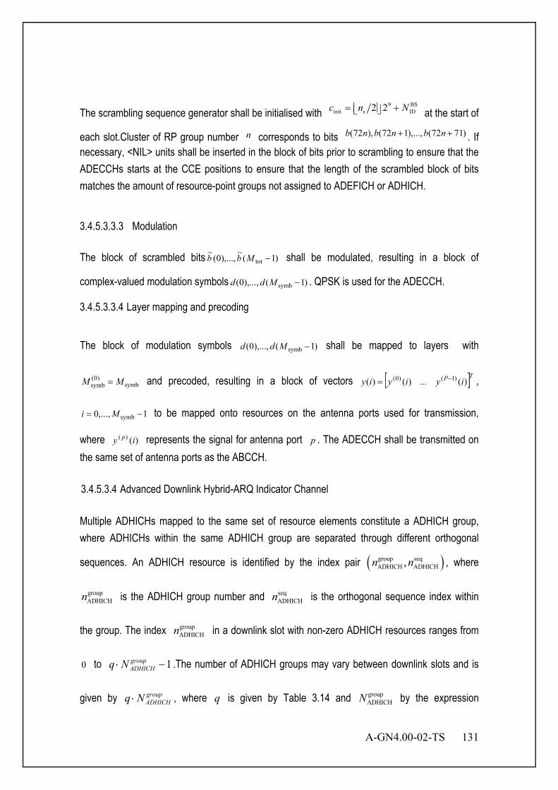
A-GN4.00-02-TS 131
The scrambling sequence generator shall be initialised with 9 BS
init s ID2 2c n N= + at the start of
each slot.Cluster of RP group number n corresponds to bits )7172(),...,172(),72( ++ nbnbnb . If necessary, <NIL> units shall be inserted in the block of bits prior to scrambling to ensure that the ADECCHs starts at the CCE positions to ensure that the length of the scrambled block of bits matches the amount of resource-point groups not assigned to ADEFICH or ADHICH.
3.4.5.3.3.3 Modulation The block of scrambled bits )1(
~),...,0(
~tot −Mbb shall be modulated, resulting in a block of
complex-valued modulation symbols )1(),...,0( symb −Mdd . QPSK is used for the ADECCH.
3.4.5.3.3.4 Layer mapping and precoding
The block of modulation symbols )1(),...,0( symb −Mdd shall be mapped to layers with
symb)0(
symb MM = and precoded, resulting in a block of vectors [ ]TP iyiyiy )(...)()( )1()0( −= ,
1,...,0 symb −= Mi to be mapped onto resources on the antenna ports used for transmission,
where )()( iy p represents the signal for antenna port p . The ADECCH shall be transmitted on the same set of antenna ports as the ABCCH. 3.4.5.3.4 Advanced Downlink Hybrid-ARQ Indicator Channel Multiple ADHICHs mapped to the same set of resource elements constitute a ADHICH group, where ADHICHs within the same ADHICH group are separated through different orthogonal
sequences. An ADHICH resource is identified by the index pair ( )group seqADHICH ADHICH,n n , where
groupADHICHn is the ADHICH group number and seq
ADHICHn is the orthogonal sequence index within
the group. The index groupADHICHn in a downlink slot with non-zero ADHICH resources ranges from
0 to 1−⋅ groupADHICHNq .The number of ADHICH groups may vary between downlink slots and is
given by groupADHICHNq ⋅ , where q is given by Table 3.14 and group
ADHICHN by the expression
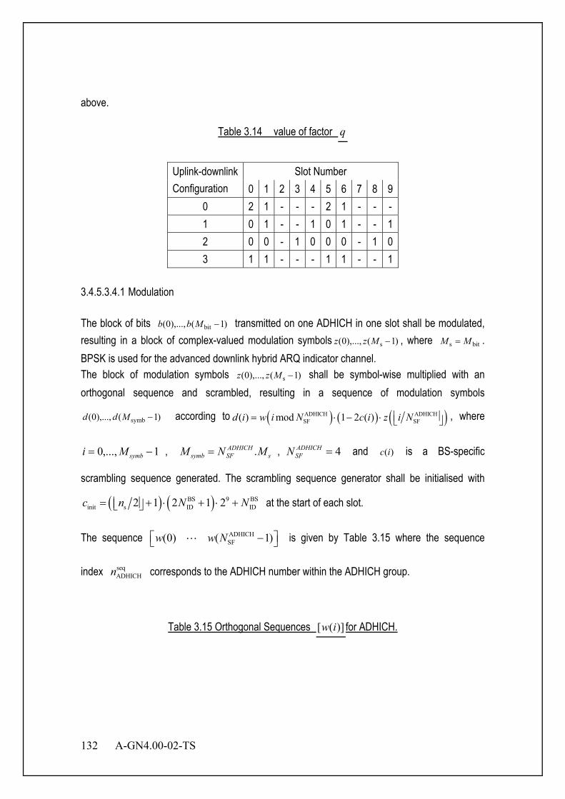
132 A-GN4.00-02-TS
above.
Table 3.14 value of factor q
Uplink-downlink Configuration
Slot Number 0 1 2 3 4 5 6 7 8 9
0 2 1 - - - 2 1 - - - 1 0 1 - - 1 0 1 - - 1 2 0 0 - 1 0 0 0 - 1 0 3 1 1 - - - 1 1 - - 1
3.4.5.3.4.1 Modulation The block of bits )1(),...,0( bit −Mbb transmitted on one ADHICH in one slot shall be modulated, resulting in a block of complex-valued modulation symbols )1(),...,0( s −Mzz , where bits MM = . BPSK is used for the advanced downlink hybrid ARQ indicator channel. The block of modulation symbols )1(),...,0( s −Mzz shall be symbol-wise multiplied with an orthogonal sequence and scrambled, resulting in a sequence of modulation symbols
)1(),...,0( symb −Mdd according to ( ) ( ) ( )ADHICH ADHICHSF SF( ) mod 1 2 ( )d i w i N c i z i N = ⋅ − ⋅ , where
1,...,0 −= symbMi , sADHICHSFsymb MNM .= , 4=ADHICH
SFN and )(ic is a BS-specific
scrambling sequence generated. The scrambling sequence generator shall be initialised with
( ) ( )BS 9 BSinit s ID ID2 1 2 1 2c n N N= + ⋅ + ⋅ + at the start of each slot.
The sequence ADHICHSF(0) ( 1)w w N − L is given by Table 3.15 where the sequence
index seqADHICHn corresponds to the ADHICH number within the ADHICH group.
Table 3.15 Orthogonal Sequences )]([ iw for ADHICH.
A-GN4.00-02-TS 133
Sequence Index seqADHICHn
Orthogonal Sequences ADHICHSF 4N =
0 [ ]1111 ++++ 1 [ ]1111 −+−+ 2 [ ]1111 −−++ 3 [ ]1111 +−−+ 4 [ ]jjjj ++++ 5 [ ]jjjj −+−+ 6 [ ]jjjj −−++ 7 [ ]jjjj +−−+
3.4.5.3.4.2 Resource group alignment, layer mapping and precoding
The block of symbols )1(),...,0( symb −Mdd should be first aligned with resource point group size,
resulting in a block of symbols )1(),...,0( symb)0()0( −⋅Mcdd , where 1=c , )()()0( idid = , for
1,...,0 symb −= Mi .The block of symbols )1(),...,0( symb)0()0( −⋅Mcdd shall be mapped to layers
and precoded, resulting in a block of vectors [ ]TP iyiyiy )(...)()( )1()0( −= , 1,...,0 symb −⋅= Mci ,
where )()( iy p represents the signal for antenna port p , 1,...,0 −= Pp and the number of antenna ports for BS-specific pilots { }4,2,1∈P . The layer mapping and precoding operation depends on the number of antenna ports used for transmission of the ADHICH. The ADHICH shall be transmitted on the same set of antenna ports as the ABCCH.
3.4.6 Null (DTX/DC Carrier/Guard carrier) for DL OFDM Null symbol is defined as 0 + 0j. It includes Discontinuous Transmission (DTX), DC carrier and Guard carrier. The details of DTX are described in Section 3.4.1.7. 3.4.7 TCCH Format for DL OFDM TCCH format is not used for DL.
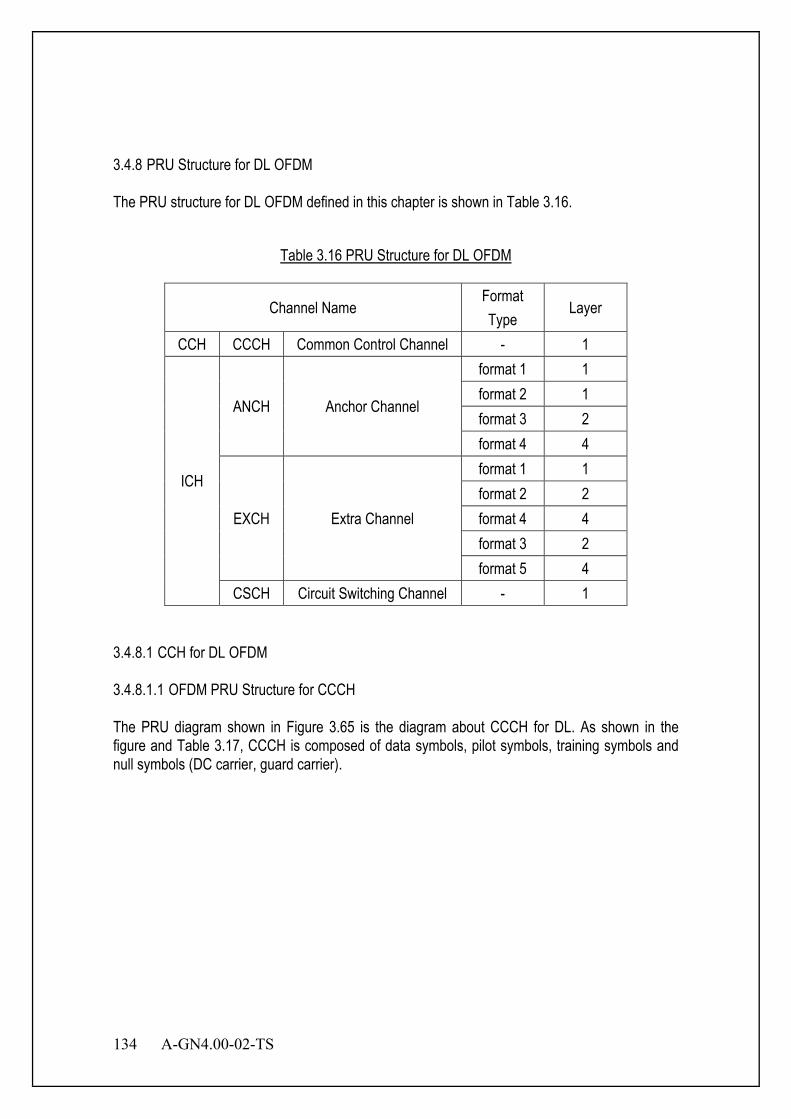
134 A-GN4.00-02-TS
3.4.8 PRU Structure for DL OFDM The PRU structure for DL OFDM defined in this chapter is shown in Table 3.16.
Table 3.16 PRU Structure for DL OFDM
Channel Name Format Type
Layer
CCH CCCH Common Control Channel - 1
ICH
ANCH Anchor Channel
format 1 1 format 2 1 format 3 2 format 4 4
EXCH Extra Channel
format 1 1 format 2 2 format 4 4 format 3 2 format 5 4
CSCH Circuit Switching Channel - 1 3.4.8.1 CCH for DL OFDM 3.4.8.1.1 OFDM PRU Structure for CCCH The PRU diagram shown in Figure 3.65 is the diagram about CCCH for DL. As shown in the figure and Table 3.17, CCCH is composed of data symbols, pilot symbols, training symbols and null symbols (DC carrier, guard carrier).
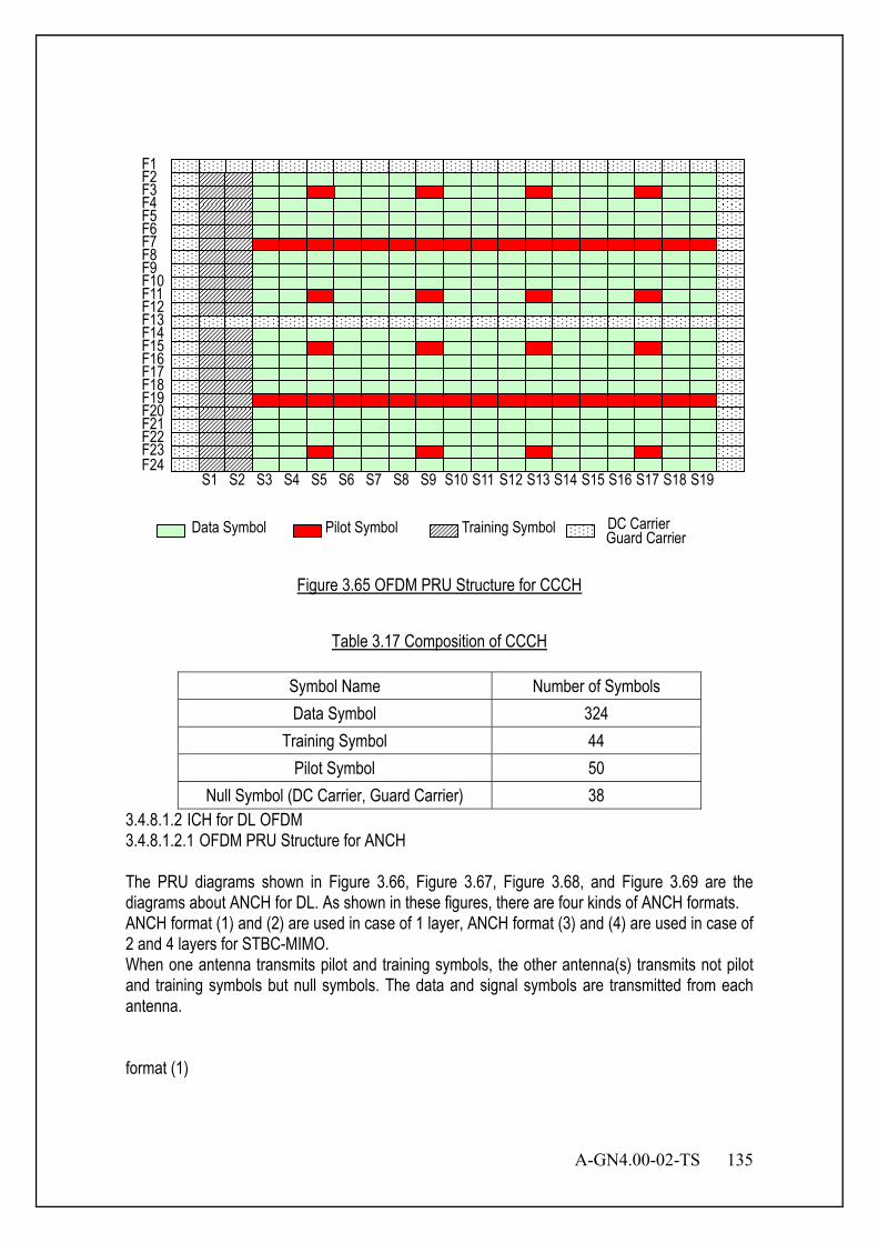
A-GN4.00-02-TS 135
DC Carrier Data Symbol Pilot Symbol Training Symbol
F23 F22 F21 F20 F19 F18 F17 F16 F15 F14 F13 F12 F11 F10 F9 F8 F7 F6 F5 F4 F3 F2 F1
F24 S1 S2 S3 S4 S5 S6 S7 S8 S9 S10 S11 S12 S13 S14 S15 S16 S17 S18 S19
Guard Carrier
Figure 3.65 OFDM PRU Structure for CCCH
Table 3.17 Composition of CCCH
Symbol Name Number of Symbols Data Symbol 324
Training Symbol 44 Pilot Symbol 50
Null Symbol (DC Carrier, Guard Carrier) 38 3.4.8.1.2 ICH for DL OFDM 3.4.8.1.2.1 OFDM PRU Structure for ANCH The PRU diagrams shown in Figure 3.66, Figure 3.67, Figure 3.68, and Figure 3.69 are the diagrams about ANCH for DL. As shown in these figures, there are four kinds of ANCH formats. ANCH format (1) and (2) are used in case of 1 layer, ANCH format (3) and (4) are used in case of 2 and 4 layers for STBC-MIMO. When one antenna transmits pilot and training symbols, the other antenna(s) transmits not pilot and training symbols but null symbols. The data and signal symbols are transmitted from each antenna. format (1)
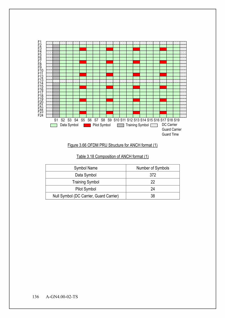
136 A-GN4.00-02-TS
Data Symbol Pilot Symbol Training Symbol
F23 F22 F21 F20 F19 F18 F17 F16 F15 F14 F13 F12 F11 F10 F9 F8 F7 F6 F5 F4 F3 F2 F1
F24 S1 S2 S3 S4 S5 S6 S7 S8 S9 S10 S11 S12 S13 S14 S15 S16 S17 S18 S19
DC Carrier Guard Carrier Guard Time
Figure 3.66 OFDM PRU Structure for ANCH format (1)
Table 3.18 Composition of ANCH format (1)
Symbol Name Number of Symbols Data Symbol 372
Training Symbol 22 Pilot Symbol 24
Null Symbol (DC Carrier, Guard Carrier) 38

A-GN4.00-02-TS 137
format (2)
Training Symbol
F23 F22 F21 F20 F19 F18 F17 F16 F15 F14 F13 F12 F11 F10 F9 F8 F7 F6 F5 F4 F3 F2 F1
F24
Data Symbol
Guard Carrier DC Carrier
Signal Symbol S1 S2 S3 S4 S5 S6 S7 S8 S9 S10 S11 S12 S13 S14 S15 S16 S17 S18 S19
Pilot Symbol
Guard Time Figure 3.67 OFDM PRU Structure for ANCH format (2)
Table 3.19 Composition of ANCH format (2)
Symbol Name Number of Symbols Data Symbol 364
Signal Symbol 8 Training Symbol 22
Pilot Symbol 24 Null Symbol (DC Carrier, Guard Carrier) 38
138 A-GN4.00-02-TS
format (3)
F23 F22 F21 F20 F19 F18 F17 F16 F15 F14 F13 F12 F11 F10 F9 F8 F7 F6 F5 F4 F3 F2 F1
F24
Data Symbol DC Carrier, Guard Carrier Guard Time
Signal Symbol S1 S2 S3 S4 S5 S6 S7 S8 S9 S10 S11 S12 S13 S14 S15 S16 S17 S18 S19
Training Symbol (Antenna1) Training Symbol (Antenna2)
Pilot Symbol (Antenna1) Pilot Symbol (Antenna2)
Figure 3.68 OFDM PRU Structure for ANCH format (3)
Table 3.20 Composition of ANCH format (3)
Symbol Name Number of Symbols Data Symbol 340
Signal Symbol 8 Training Symbol(Antenna1) 12 Training Symbol(Antenna2) 10
Pilot Symbol(Antenna1) 24 Pilot Symbol(Antenna2) 24
Null Symbol (DC Carrier, Guard Carrier) 38

A-GN4.00-02-TS 139
format (4)
F23 F22 F21 F20 F19 F18 F17 F16 F15 F14 F13 F12 F11 F10 F9 F8 F7 F6 F5 F4 F3 F2 F1
F24
Data Symbol DC Carrier, Guard Carrier Guard Time
Signal Symbol
S1 S2 S3 S4 S5 S6 S7 S8 S9 S10 S11 S12 S13 S14 S15 S16 S17 S18 S19
Training Symbol (Antenna1) Training Symbol (Antenna2) Training Symbol (Antenna3) Training Symbol (Antenna4) Pilot Symbol (Antenna1) Pilot Symbol (Antenna2) Pilot Symbol (Antenna3) Pilot Symbol (Antenna4)
Figure 3.69 OFDM PRU Structure for ANCH format (4)
Table 3.21 Composition of ANCH format (4)
Symbol Name Number of Symbols Data Symbol 340
Signal Symbol 8 Training Symbol(Antenna1) 6 Training Symbol(Antenna2) 6 Training Symbol(Antenna3) 6 Training Symbol(Antenna4) 4
Pilot Symbol(Antenna1) 12 Pilot Symbol(Antenna2) 12 Pilot Symbol(Antenna3) 12 Pilot Symbol(Antenna4) 12
Null Symbol (DC Carrier, Guard Carrier) 38

140 A-GN4.00-02-TS
3.4.8.1.3 OFDM PRU Structure for EXCH The PRU diagrams shown in Figure 3.70, Figure 3.71, Figure 3.73, Figure 3.74 and Figure 3.72 are the diagrams about EXCH for DL. As shown in these figures, there are five kinds of EXCH formats. EXCH format (a-1), (a-2), (a-3), (a-4) and (a-5) have always DC carrier and guard carrier. These formats are the cases that full subcarrier mode is not used. The PRU diagrams shown in Figure 3.75, Figure 3.76 and Figure 3.77 are the diagrams about EXCH for DL. As shown in these figures, there are three kinds of EXCH formats. EXCH formats (b), (c) and (d) are the case that full subcarrier mode is used. EXCH format (b) is used for all SCHs except central SCH to which EXCH format (c) or (d) is applied. EXCH Format (a-1) is used in case of 1 layer. EXCH Format (a-2) and (a-4) are used in case of 2 and 4 layers for SM and STBC-MIMO. EXCH Format (a-3) and (a-5) are used in case of 2 and 4 layers for EMB and STBC-MIMO. There are two and four kinds of arrangement for pilot and training symbols. When one antenna transmits pilot and training symbols, the other antenna(s) transmits not pilot and training symbols but null symbols. The data and signal symbols are transmitted from each antenna. As for training symbol for EXCH format (b), (c), (d), refer to 3.4.2.3.2.3. EXCH data size depends on EXCH format and MCS which is indicated by ANCH/ECCH. Moreover, each EXCH data size shall be equal to the number of bits which can be accommodated in one or two PRU.
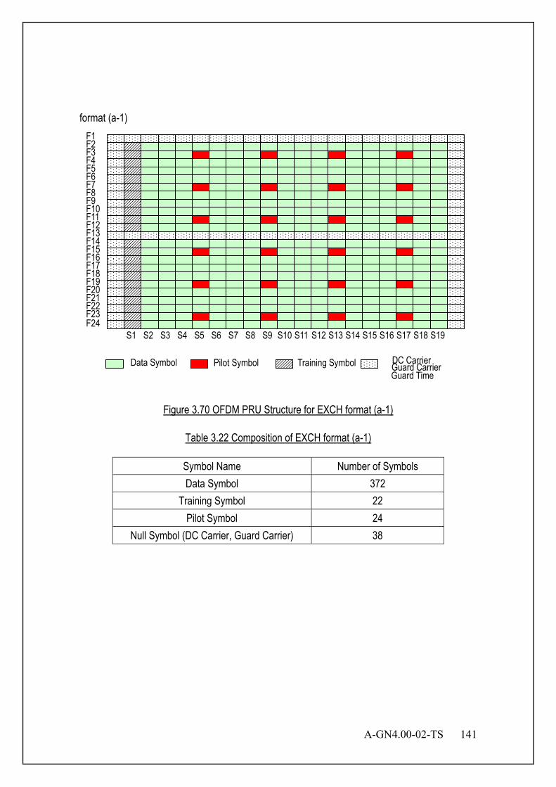
A-GN4.00-02-TS 141
format (a-1)
Data Symbol Pilot Symbol Training Symbol Guard Carrier Guard Time
F23 F22 F21 F20 F19 F18 F17 F16 F15 F14 F13 F12 F11 F10 F9 F8 F7 F6 F5 F4 F3 F2 F1
F24 S1 S2 S3 S4 S5 S6 S7 S8 S9 S10 S11 S12 S13 S14 S15 S16 S17 S18 S19
DC Carrier
Figure 3.70 OFDM PRU Structure for EXCH format (a-1)
Table 3.22 Composition of EXCH format (a-1)
Symbol Name Number of Symbols Data Symbol 372
Training Symbol 22 Pilot Symbol 24
Null Symbol (DC Carrier, Guard Carrier) 38

142 A-GN4.00-02-TS
format (a-2)
F23 F22 F21 F20 F19 F18 F17 F16 F15 F14 F13 F12 F11 F10 F9 F8 F7 F6 F5 F4 F3 F2 F1
F24
Data Symbol DC Carrier Guard Carrier Guard Time
S1 S2 S3 S4 S5 S6 S7 S8 S9 S10 S11 S12 S13 S14 S15 S16 S17 S18 S19
Training Symbol (Antenna1) Training Symbol (Antenna2)
Pilot Symbol (Antenna1) Pilot Symbol (Antenna2)
Figure 3.71 OFDM PRU Structure for EXCH format (a-2)
Table 3.23 Composition of EXCH format (a-2)
Symbol Name Number of Symbols Data Symbol 348
Training Symbol(Antenna1) 12 Training Symbol(Antenna2) 10
Pilot Symbol(Antenna1) 24 Pilot Symbol(Antenna2) 24
Null Symbol (DC Carrier, Guard Carrier) 38
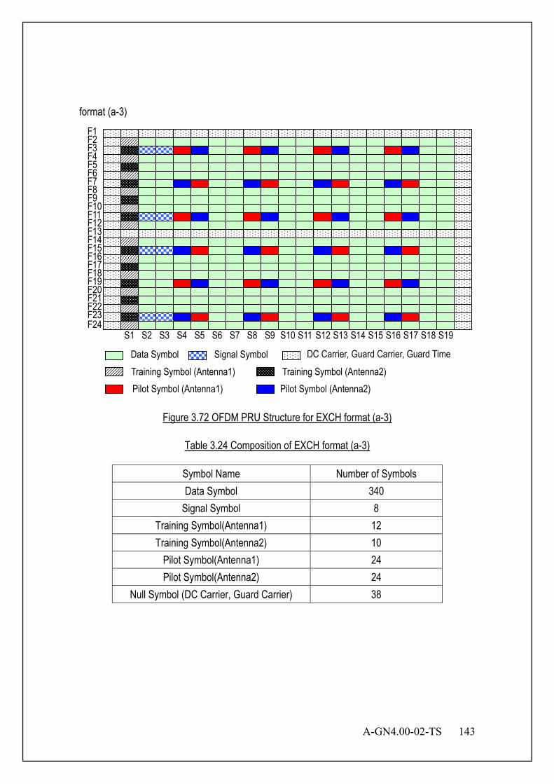
A-GN4.00-02-TS 143
format (a-3)
Signal Symbol
F23 F22 F21 F20 F19 F18 F17 F16 F15 F14 F13 F12 F11 F10 F9 F8 F7 F6 F5 F4 F3 F2 F1
F24
Data Symbol DC Carrier, Guard Carrier, Guard Time
S1 S2 S3 S4 S5 S6 S7 S8 S9 S10 S11 S12 S13 S14 S15 S16 S17 S18 S19
Training Symbol (Antenna1) Training Symbol (Antenna2) Pilot Symbol (Antenna1) Pilot Symbol (Antenna2)
Figure 3.72 OFDM PRU Structure for EXCH format (a-3)
Table 3.24 Composition of EXCH format (a-3)
Symbol Name Number of Symbols Data Symbol 340
Signal Symbol 8 Training Symbol(Antenna1) 12 Training Symbol(Antenna2) 10
Pilot Symbol(Antenna1) 24 Pilot Symbol(Antenna2) 24
Null Symbol (DC Carrier, Guard Carrier) 38

144 A-GN4.00-02-TS
format (a-4)
F23 F22 F21 F20 F19 F18 F17 F16 F15 F14 F13 F12 F11 F10 F9 F8 F7 F6 F5 F4 F3 F2 F1
F24
Data Symbol
S1 S2 S3 S4 S5 S6 S7 S8 S9 S10 S11 S12 S13 S14 S15 S16 S17 S18 S19
DC Carrier, Guard Carrier, Guard Time
Training Symbol (Antenna1)
Training Symbol (Antenna2)
Training Symbol (Antenna3)
Training Symbol (Antenna4)
Pilot Symbol (Antenna1) Pilot Symbol (Antenna2)
Pilot Symbol (Antenna3) Pilot Symbol (Antenna4)
Figure 3.73 OFDM PRU Structure for EXCH format (a-4)
Table 3.25 Composition of EXCH format (a-4)
Symbol Name Number of Symbols Data Symbol 348
Training Symbol(Antenna1) 6 Training Symbol(Antenna2) 6 Training Symbol(Antenna3) 6 Training Symbol(Antenna4) 4
Pilot Symbol(Antenna1) 12 Pilot Symbol(Antenna2) 12 Pilot Symbol(Antenna3) 12 Pilot Symbol(Antenna4) 12
Null Symbol (DC Carrier, Guard Carrier) 38
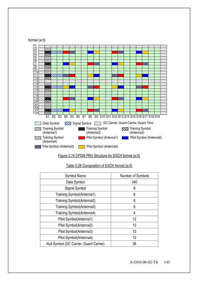
A-GN4.00-02-TS 145
format (a-5)
F23 F22 F21 F20 F19 F18 F17 F16 F15 F14 F13 F12 F11 F10 F9 F8 F7 F6 F5 F4 F3 F2 F1
F24
Data Symbol Signal Symbol
S1 S2 S3 S4 S5 S6 S7 S8 S9 S10 S11 S12 S13 S14 S15 S16 S17 S18 S19
DC Carrier, Guard Carrier, Guard Time Training Symbol (Antenna1)
Training Symbol (Antenna2)
Training Symbol (Antenna3)
Training Symbol (Antenna4)
Pilot Symbol (Antenna1) Pilot Symbol (Antenna2)
Pilot Symbol (Antenna3) Pilot Symbol (Antenna4)
Figure 3.74 OFDM PRU Structure for EXCH format (a-5)
Table 3.26 Composition of EXCH format (a-5)
Symbol Name Number of Symbols Data Symbol 340
Signal Symbol 8 Training Symbol(Antenna1) 6 Training Symbol(Antenna2) 6 Training Symbol(Antenna3) 6 Training Symbol(Antenna4) 4
Pilot Symbol(Antenna1) 12 Pilot Symbol(Antenna2) 12 Pilot Symbol(Antenna3) 12 Pilot Symbol(Antenna4) 12
Null Symbol (DC Carrier, Guard Carrier) 38

146 A-GN4.00-02-TS
As shown in Figure 3.75, the training symbol of F1 is a copy of F12. The training symbol of F13 is a copy of F24. format (b)
Guard Time Data Symbol Pilot Symbol Training Symbol
Copy
Copy
F23 F22 F21 F20 F19 F18 F17 F16 F15 F14 F13 F12 F11 F10 F9 F8 F7 F6 F5 F4 F3 F2 F1
F24 S1 S2 S3 S4 S5 S6 S7 S8 S9 S10 S11 S12 S13 S14 S15 S16 S17 S18 S19
Figure 3.75 OFDM PRU Structure for EXCH format (b)
Table 3.27 Composition of EXCH format (b)
Symbol Name Number of Symbols Data Symbol 408
Training Symbol 24 Pilot Symbol 24 Null Symbol 0
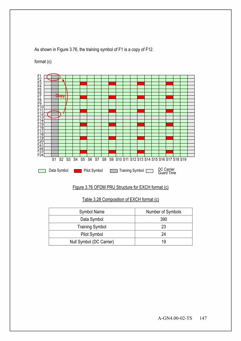
A-GN4.00-02-TS 147
As shown in Figure 3.76, the training symbol of F1 is a copy of F12. format (c)
Data Symbol Pilot Symbol Training Symbol Guard Time DC Carrier
Copy
F23 F22 F21 F20 F19 F18 F17 F16 F15 F14 F13 F12 F11 F10 F9 F8 F7 F6 F5 F4 F3 F2 F1
F24 S1 S2 S3 S4 S5 S6 S7 S8 S9 S10 S11 S12 S13 S14 S15 S16 S17 S18 S19
Figure 3.76 OFDM PRU Structure for EXCH format (c)
Table 3.28 Composition of EXCH format (c)
Symbol Name Number of Symbols Data Symbol 390
Training Symbol 23 Pilot Symbol 24
Null Symbol (DC Carrier) 19
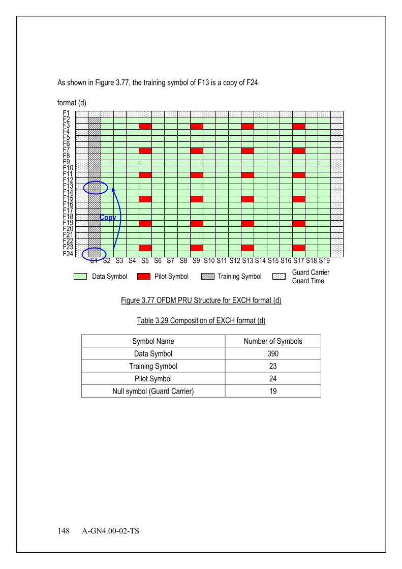
148 A-GN4.00-02-TS
As shown in Figure 3.77, the training symbol of F13 is a copy of F24. format (d)
Data Symbol Pilot Symbol Training Symbol Guard Carrier Guard Time
Copy
F23 F22 F21 F20 F19 F18 F17 F16 F15 F14 F13 F12 F11 F10 F9 F8 F7 F6 F5 F4 F3 F2 F1
F24 S1 S2 S3 S4 S5 S6 S7 S8 S9 S10 S11 S12 S13 S14 S15 S16 S17 S18 S19
Figure 3.77 OFDM PRU Structure for EXCH format (d)
Table 3.29 Composition of EXCH format (d)
Symbol Name Number of Symbols Data Symbol 390
Training Symbol 23 Pilot Symbol 24
Null symbol (Guard Carrier) 19
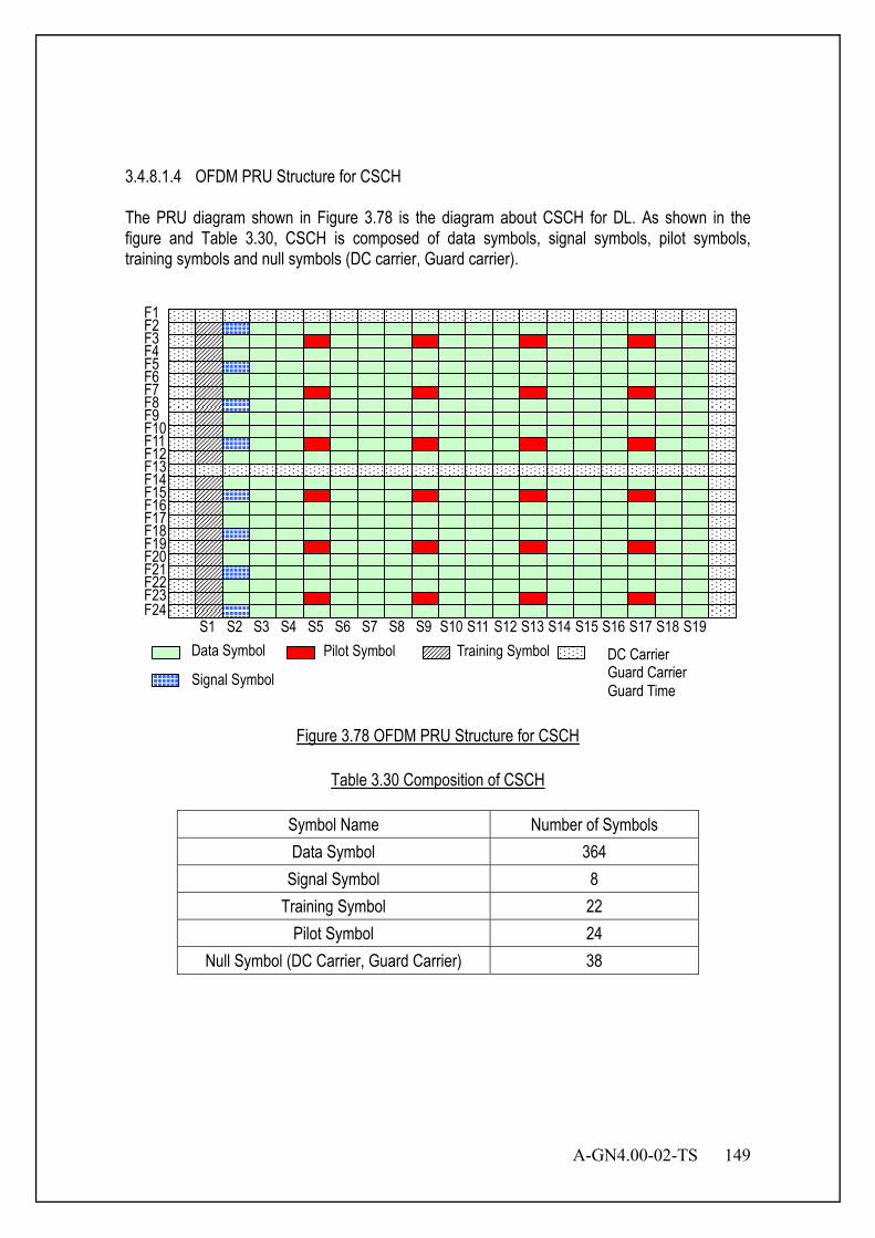
A-GN4.00-02-TS 149
3.4.8.1.4 OFDM PRU Structure for CSCH The PRU diagram shown in Figure 3.78 is the diagram about CSCH for DL. As shown in the figure and Table 3.30, CSCH is composed of data symbols, signal symbols, pilot symbols, training symbols and null symbols (DC carrier, Guard carrier).
F23 F22 F21 F20 F19 F18 F17 F16 F15 F14 F13 F12 F11 F10 F9 F8 F7 F6 F5 F4 F3 F2 F1
F24
Data Symbol Pilot Symbol Training Symbol DC Carrier Guard Carrier Guard Time
Signal Symbol
S1 S2 S3 S4 S5 S6 S7 S8 S9 S10 S11 S12 S13 S14 S15 S16 S17 S18 S19
Figure 3.78 OFDM PRU Structure for CSCH
Table 3.30 Composition of CSCH
Symbol Name Number of Symbols Data Symbol 364
Signal Symbol 8 Training Symbol 22
Pilot Symbol 24 Null Symbol (DC Carrier, Guard Carrier) 38
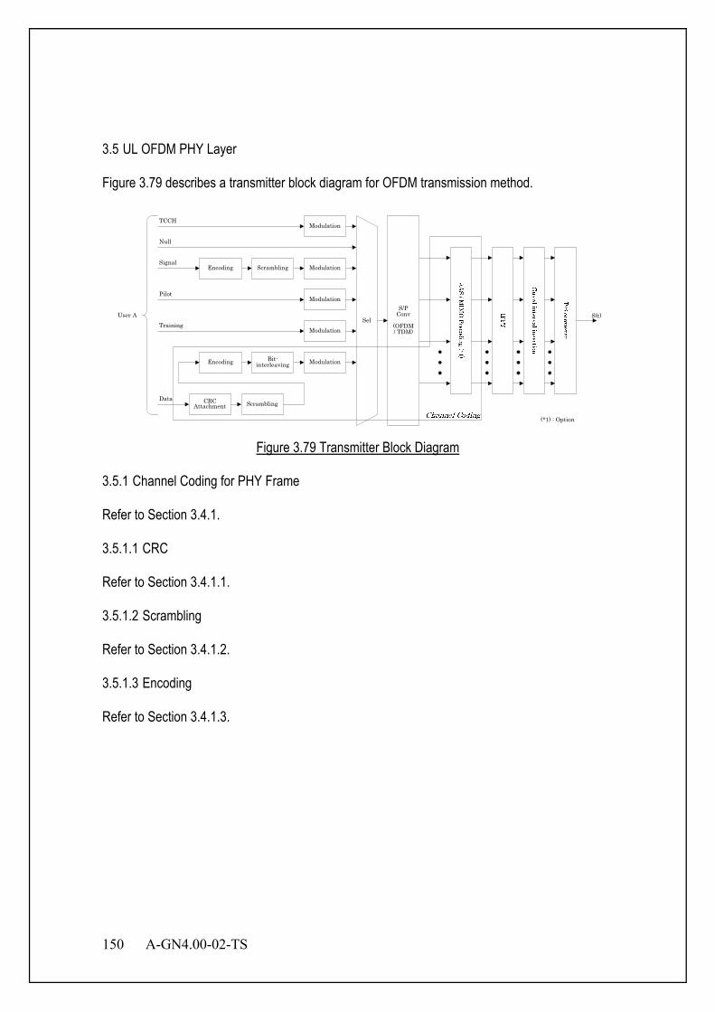
150 A-GN4.00-02-TS
3.5 UL OFDM PHY Layer Figure 3.79 describes a transmitter block diagram for OFDM transmission method.
Data
Sel
Pilot
Training
CRCAttachment
ModulationEncoding Bit-interleaving
Scrambling
Modulation
Signal
User A S(t)S/P
Conv
(OFDM / TDM)
Modulation
ModulationEncoding Scrambling
Null
TCCHModulation
(*1) : Option
Figure 3.79 Transmitter Block Diagram
3.5.1 Channel Coding for PHY Frame Refer to Section 3.4.1. 3.5.1.1 CRC Refer to Section 3.4.1.1. 3.5.1.2 Scrambling Refer to Section 3.4.1.2. 3.5.1.3 Encoding Refer to Section 3.4.1.3.
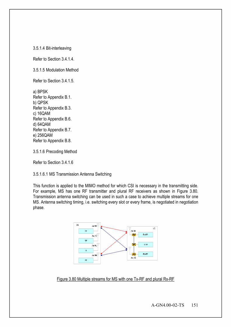
A-GN4.00-02-TS 151
3.5.1.4 Bit-interleaving Refer to Section 3.4.1.4. 3.5.1.5 Modulation Method Refer to Section 3.4.1.5. a) BPSK Refer to Appendix B.1. b) QPSK Refer to Appendix B.3. c) 16QAM Refer to Appendix B.6. d) 64QAM Refer to Appendix B.7. e) 256QAM Refer to Appendix B.8. 3.5.1.6 Precoding Method Refer to Section 3.4.1.6 3.5.1.6.1 MS Transmission Antenna Switching This function is applied to the MIMO method for which CSI is necessary in the transmitting side. For example, MS has one RF transmitter and plural RF receivers as shown in Figure 3.80. Transmission antenna switching can be used in such a case to achieve multiple streams for one MS. Antenna switching timing, i.e. switching every slot or every frame, is negotiated in negotiation phase.
Figure 3.80 Multiple streams for MS with one Tx-RF and plural Rx-RF
152 A-GN4.00-02-TS
3.5.1.7 Symbol Mapping Method to PRU Refer to Section 3.4.1.7. 3.5.1.8 Summary of OFDM UL Channel Coding Refer to Section 3.4.1.8. 3.5.1.9 Training for UL OFDM Refer to Section 3.4.2. 3.5.1.10 UL Training Sequence for MS transmission frame antenna switching When the number of MS transmitter is one and the number of MS transmission antenna is two or more and MS supports antenna switching, UL core-sequence number for MS transmission frame antenna switching is calculated as follows: UL Core-sequence Number : x = [(A+{Fk -1 MOD 4}) MOD 12] + 1 Fk = active frame number (Fk=1,2,…) Fk is incremented every frame. Fk shall be initialized each scheduling term. The parameter except for UL core-sequence number is same as Section 3.4.2.3.2.2. 3.5.1.11 UL Training Sequence for MS transmission slot antenna switching When the number of MS transmitter is one and the number of MS transmission antenna is two or more and MS supports antenna switching, UL core-sequence number for MS transmission slot antenna switching is calculated as follows: UL Core-sequence Number : x = [(A+{Sk -1 MOD 4}) MOD 12] + 1 Sk = absolute slot number (Sk=1,2,3,4) The parameter except for UL core-sequence number is same as Section 3.4.2.3.2.2. 3.5.2 Pilot for UL OFDM Refer to Section 3.4.3. 3.5.3 Signal for UL OFDM Refer to Section 3.4.5. 3.5.4 Null (DTX/DC Carrier/Guard Carrier) for UL OFDM Refer to Section 3.4.6.
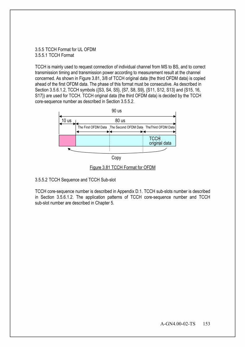
A-GN4.00-02-TS 153
3.5.5 TCCH Format for UL OFDM 3.5.5.1 TCCH Format TCCH is mainly used to request connection of individual channel from MS to BS, and to correct transmission timing and transmission power according to measurement result at the channel concerned. As shown in Figure 3.81, 3/8 of TCCH original data (the third OFDM data) is copied ahead of the first OFDM data. The phase of this format must be consecutive. As described in Section 3.5.6.1.2, TCCH symbols ({S3, S4, S5}, {S7, S8, S9}, {S11, S12, S13} and {S15, 16, S17}) are used for TCCH. TCCH original data (the third OFDM data) is decided by the TCCH core-sequence number as described in Section 3.5.5.2.
Figure 3.81 TCCH Format for OFDM 3.5.5.2 TCCH Sequence and TCCH Sub-slot TCCH core-sequence number is described in Appendix D.1. TCCH sub-slots number is described in Section 3.5.6.1.2. The application patterns of TCCH core-sequence number and TCCH sub-slot number are described in Chapter 5.
TCCH
10 us 80 us
Copy
90 us
original data
The First OFDM Data The Second OFDM Data TheThird OFDM Data
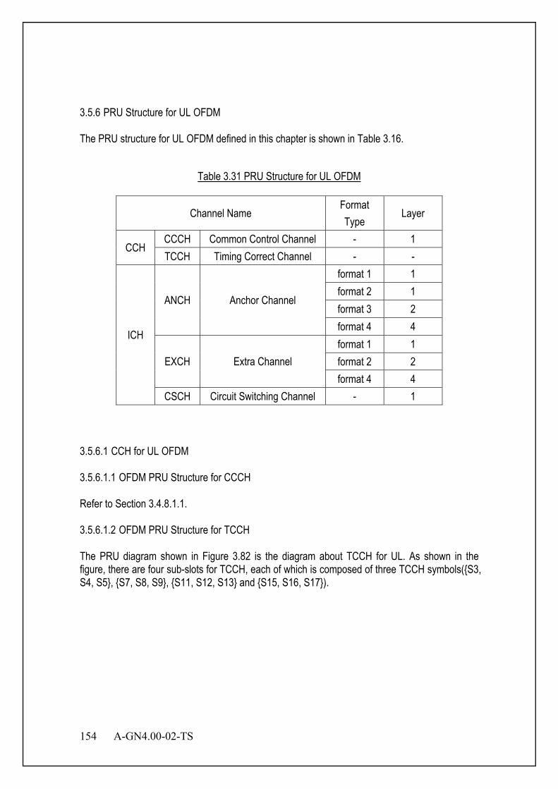
154 A-GN4.00-02-TS
3.5.6 PRU Structure for UL OFDM The PRU structure for UL OFDM defined in this chapter is shown in Table 3.16.
Table 3.31 PRU Structure for UL OFDM
Channel Name Format Type
Layer
CCH CCCH Common Control Channel - 1 TCCH Timing Correct Channel - -
ICH
ANCH Anchor Channel
format 1 1 format 2 1 format 3 2 format 4 4
EXCH Extra Channel format 1 1 format 2 2 format 4 4
CSCH Circuit Switching Channel - 1 3.5.6.1 CCH for UL OFDM 3.5.6.1.1 OFDM PRU Structure for CCCH Refer to Section 3.4.8.1.1. 3.5.6.1.2 OFDM PRU Structure for TCCH The PRU diagram shown in Figure 3.82 is the diagram about TCCH for UL. As shown in the figure, there are four sub-slots for TCCH, each of which is composed of three TCCH symbols({S3, S4, S5}, {S7, S8, S9}, {S11, S12, S13} and {S15, S16, S17}).
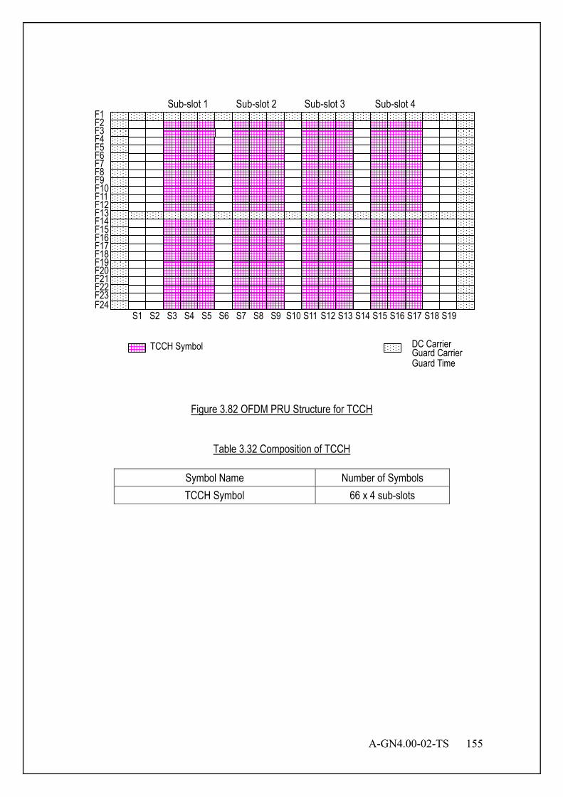
A-GN4.00-02-TS 155
DC Carrier
Guard Time
S1 S2 S3 S4 S5 S6 S7 S8 S9 S10 S11 S12 S13 S14 S15 S16 S17 S18 S19
TCCH Symbol
Sub-slot 1 Sub-slot 2 Sub-slot 3 Sub-slot 4
F23 F22 F21 F20 F19 F18 F17 F16 F15 F14 F13 F12 F11 F10 F9 F8 F7 F6 F5 F4 F3 F2 F1
F24
Guard Carrier
Figure 3.82 OFDM PRU Structure for TCCH
Table 3.32 Composition of TCCH
Symbol Name Number of Symbols TCCH Symbol 66 x 4 sub-slots
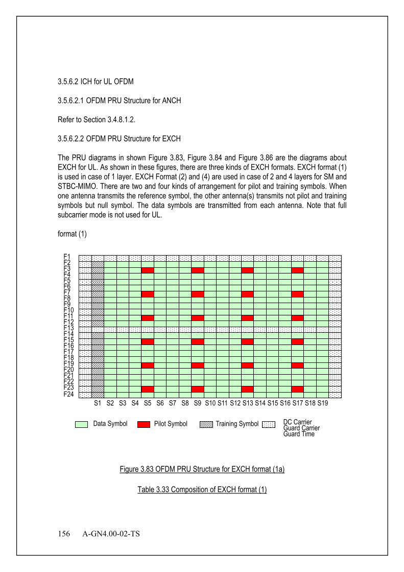
156 A-GN4.00-02-TS
3.5.6.2 ICH for UL OFDM 3.5.6.2.1 OFDM PRU Structure for ANCH Refer to Section 3.4.8.1.2. 3.5.6.2.2 OFDM PRU Structure for EXCH The PRU diagrams in shown Figure 3.83, Figure 3.84 and Figure 3.86 are the diagrams about EXCH for UL. As shown in these figures, there are three kinds of EXCH formats. EXCH format (1) is used in case of 1 layer. EXCH Format (2) and (4) are used in case of 2 and 4 layers for SM and STBC-MIMO. There are two and four kinds of arrangement for pilot and training symbols. When one antenna transmits the reference symbol, the other antenna(s) transmits not pilot and training symbols but null symbol. The data symbols are transmitted from each antenna. Note that full subcarrier mode is not used for UL. format (1)
Data Symbol Pilot Symbol Training Symbol Guard Carrier Guard Time
F23 F22 F21 F20 F19 F18 F17 F16 F15 F14 F13 F12 F11 F10 F9 F8 F7 F6 F5 F4 F3 F2 F1
F24 S1 S2 S3 S4 S5 S6 S7 S8 S9 S10 S11 S12 S13 S14 S15 S16 S17 S18 S19
DC Carrier
Figure 3.83 OFDM PRU Structure for EXCH format (1a)
Table 3.33 Composition of EXCH format (1)

A-GN4.00-02-TS 157
Symbol Name Number of Symbols Data Symbol 372
Training Symbol 22 Pilot Symbol 24
Null Symbol (DC carrier, Guard Carrier) 38 format (2)
F23 F22 F21 F20 F19 F18 F17 F16 F15 F14 F13 F12 F11 F10 F9 F8 F7 F6 F5 F4 F3 F2 F1
F24
Data Symbol DC Carrier Guard Carrier Guard Time
S1 S2 S3 S4 S5 S6 S7 S8 S9 S10 S11 S12 S13 S14 S15 S16 S17 S18 S19
Training Symbol (Antenna1) Training Symbol (Antenna2)
Pilot Symbol (Antenna1) Pilot Symbol (Antenna2)
Figure 3.84 OFDM PRU Structure for EXCH format (2)
Table 3.34 Composition of EXCH format (2)
Symbol Name Number of Symbols Data Symbol 348
Training Symbol(Antenna 1) 12 Training Symbol(Antenna 2) 10 Pilot Symbol(Anntenna 1) 24 Pilot Symbol(Anntenna 2) 24
Null Symbol (DC carrier, Guard Carrier) 38
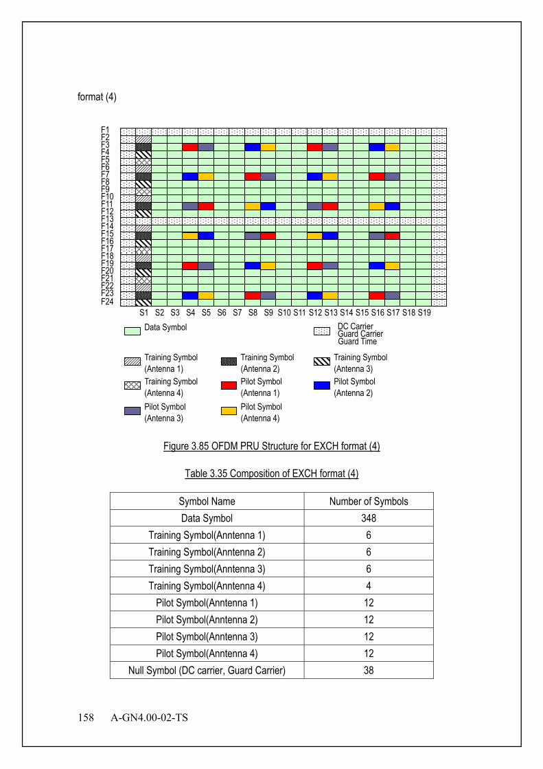
158 A-GN4.00-02-TS
format (4)
Data Symbol
Pilot Symbol (Antenna 1)
Training Symbol (Antenna 1)
Guard Carrier Guard Time
F23 F22 F21 F20 F19 F18 F17 F16 F15 F14 F13 F12 F11 F10 F9 F8 F7 F6 F5 F4 F3 F2 F1
F24 S1 S2 S3 S4 S5 S6 S7 S8 S9 S10 S11 S12 S13 S14 S15 S16 S17 S18 S19
DC Carrier
Training Symbol (Antenna 2)
Pilot Symbol (Antenna 2)
Training Symbol (Antenna 3)
Training Symbol (Antenna 4) Pilot Symbol (Antenna 3)
Pilot Symbol (Antenna 4)
Figure 3.85 OFDM PRU Structure for EXCH format (4)
Table 3.35 Composition of EXCH format (4)
Symbol Name Number of Symbols Data Symbol 348
Training Symbol(Anntenna 1) 6 Training Symbol(Anntenna 2) 6 Training Symbol(Anntenna 3) 6 Training Symbol(Anntenna 4) 4
Pilot Symbol(Anntenna 1) 12 Pilot Symbol(Anntenna 2) 12 Pilot Symbol(Anntenna 3) 12 Pilot Symbol(Anntenna 4) 12
Null Symbol (DC carrier, Guard Carrier) 38

A-GN4.00-02-TS 159
3.5.6.2.3 OFDM PRU Structure for CSCH Refer to Section 3.4.8.1.4. 3.6 UL SC PHY Layer Figure 3.86 describes a transmitter block diagram for SC transmission method.
Figure 3.86 Transmitter Block Diagram for SC Transmission Method
Figure 3.87 describes an optional transmitter block diagram for SC transmission method.
DFT Sub-carrier
Mapping GI
insertion
Size-NTX Size-NFFT
Coded symbol rate= R
NTX symbols
IFFT
Figure 3.87 Transmitter structure for SC-FDMA 3.6.1 Channel Coding for PHY Frame PHY frame consists of one or more Cyclic Redundancy Check (CRC) data unit(s). CRC-bits are first appended to the CRC data unit. Then tail-bits are appended to the CRC data unit with
Sel
Null
SignalEncoding Scrambling Modulation
PilotModulation
Training Modulation
Data
ModulationBit-interleaving
EncodingScrambling
ModulationTCCH
S(t)
User A
CRC Attachment
SC Block Construction
Guard Interval
Insertion
Pulse Shaping
Filter
Channel Coding
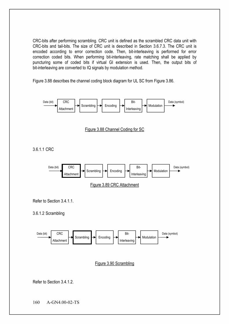
160 A-GN4.00-02-TS
CRC-bits after performing scrambling. CRC unit is defined as the scrambled CRC data unit with CRC-bits and tail-bits. The size of CRC unit is described in Section 3.6.7.3. The CRC unit is encoded according to error correction code. Then, bit-interleaving is performed for error correction coded bits. When performing bit-interleaving, rate matching shall be applied by puncturing some of coded bits if virtual GI extension is used. Then, the output bits of bit-interleaving are converted to IQ signals by modulation method. Figure 3.88 describes the channel coding block diagram for UL SC from Figure 3.86.
Figure 3.88 Channel Coding for SC
3.6.1.1 CRC
Figure 3.89 CRC Attachment
Refer to Section 3.4.1.1. 3.6.1.2 Scrambling
Figure 3.90 Scrambling
Refer to Section 3.4.1.2.
CRC
Attachment Scrambling Encoding
Bit-
Interleaving Modulation
Data (bit) Data (symbol)
CRC
Attachment Scrambling Encoding
Bit-
Interleaving Modulation
Data (bit) Data (symbol)
CRC
Attachment Scrambling Encoding
Bit-
Interleaving Modulation
Data (bit) Data (symbol)
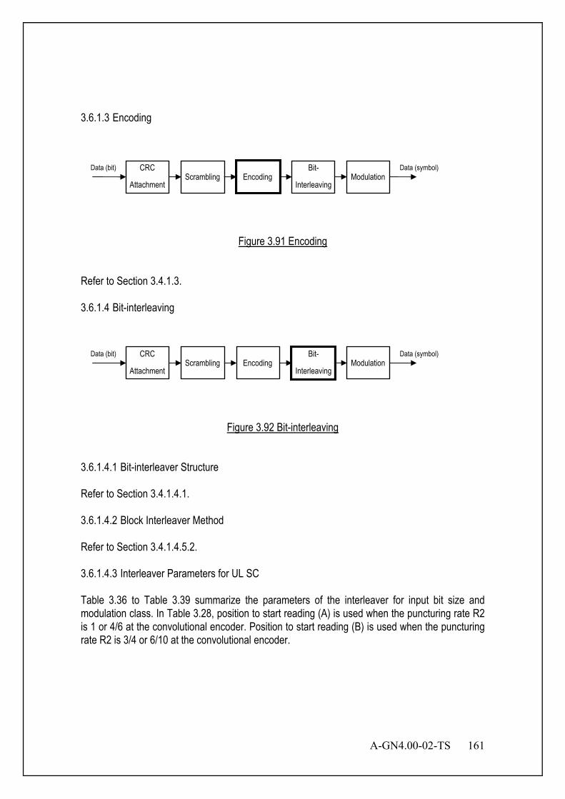
A-GN4.00-02-TS 161
3.6.1.3 Encoding
Figure 3.91 Encoding
Refer to Section 3.4.1.3. 3.6.1.4 Bit-interleaving
Figure 3.92 Bit-interleaving
3.6.1.4.1 Bit-interleaver Structure Refer to Section 3.4.1.4.1. 3.6.1.4.2 Block Interleaver Method Refer to Section 3.4.1.4.5.2. 3.6.1.4.3 Interleaver Parameters for UL SC Table 3.36 to Table 3.39 summarize the parameters of the interleaver for input bit size and modulation class. In Table 3.28, position to start reading (A) is used when the puncturing rate R2 is 1 or 4/6 at the convolutional encoder. Position to start reading (B) is used when the puncturing rate R2 is 3/4 or 6/10 at the convolutional encoder.
CRC
Attachment Scrambling Encoding
Bit-
Interleaving Modulation
Data (bit) Data (symbol)
CRC
Attachment Scrambling Encoding
Bit-
Interleaving Modulation
Data (bit) Data (symbol)

162 A-GN4.00-02-TS
Table 3.36 Interleaver Parameter M and N
Physical Channel Number of Symbols: y
M N
CCH 240 15 16 ICH (One PRU) 256 16 16 ICH (Otherwise) 512 32 16
Table 3.37 Interleaver Parameter
Modulation The Number of Block Interleavers BPSK 1 QPSK 2 8PSK 3 16QAM 4 64QAM 6 256QAM 8
Table 3.38 The Definition of Bit Position i in a Symbol
Modulation Bit Position i in a Symbol BPSK i = (1) QPSK i = (1,2) 8PSK i = (1,2,3) 16QAM i = (1,2,3,4) 64QAM i = (1,2,3,4,5,6) 256QAM i = (1,2,3,4,5,6,7,8)
Table 3.39 Starting Position for Interleaver
Bit Position i in a Symbol
Position to Start Writing
Position to Start Reading (A)
Position to Start Reading (B)
1 a1,1 a1,1 a1,1 2 a1,1 a1,2 a1,1 3 a1,1 a1,3 a1,2 4 a1,1 a1,4 a1,2 5 a1,1 a1,8 a1,2 6 a1,1 a1,9 a1,1 7 a1,1 a1,10 N/A 8 a1,1 a1,7 N/A
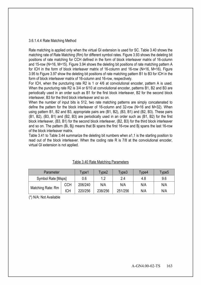
A-GN4.00-02-TS 163
3.6.1.4.4 Rate Matching Method Rate matching is applied only when the virtual GI extension is used for SC. Table 3.40 shows the matching rate of Rate Matching (Rm) for different symbol rates. Figure 3.93 shows the deleting bit positions of rate matching for CCH defined in the form of block interleaver matrix of 16-column and 15-row (N=16, M=15). Figure 3.94 shows the deleting bit positions of rate matching pattern A for ICH in the form of block interleaver matrix of 16-column and 16-row (N=16, M=16). Figure 3.95 to Figure 3.97 show the deleting bit positions of rate matching pattern B1 to B3 for ICH in the form of block interleaver matrix of 16-column and 16-row, respectively. For ICH, when the puncturing rate R2 is 1 or 4/6 at convolutional encoder, pattern A is used. When the puncturing rate R2 is 3/4 or 6/10 at convolutional encoder, patterns B1, B2 and B3 are periodically used in an order such as B1 for the first block interleaver, B2 for the second block interleaver, B3 for the third block interleaver and so on. When the number of input bits is 512, two rate matching patterns are simply concatenated to define the pattern for the block interleaver of 16-column and 32-row (N=16 and M=32). When using pattern B1, B2 and B3, appropriate pairs are (B1, B2), (B3, B1) and (B2, B3). These pairs (B1, B2), (B3, B1) and (B2, B3) are periodically used in an order such as (B1, B2) for the first block interleaver, (B3, B1) for the second block interleaver, (B2, B3) for the third block interleaver and so on. The pattern (Bi, Bj) means that Bi spans the first 16-row and Bj spans the last 16-row of the block interleaver matrix. Table 3.41 to Table 3.44 summarize the deleting bit numbers when a1,1 is the starting position to read out of the block interleaver. When the coding rate R is 7/8 at the convolutional encoder, virtual GI extension is not applied.
Table 3.40 Rate Matching Parameters
Parameter Type1 Type2 Type3 Type4 Type5 Symbol Rate [Msps] 0.6 1.2 2.4 4.8 9.6
Matching Rate: Rm CCH 206/240 N/A N/A N/A N/A ICH 220/256 238/256 251/256 N/A N/A
(*) N/A: Not Available
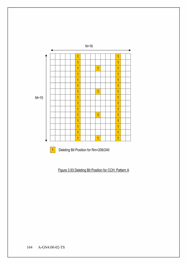
164 A-GN4.00-02-TS
Figure 3.93 Deleting Bit Position for CCH: Pattern A
1 1
1 1
1 1 1
1 1
1 1
1 1
1 1 1
1 1
1 1
1 1
1 1 1
1 1
1 1
1 1
1 1 1
1 Deleting Bit Position for Rm=206/240
N=16
M=15
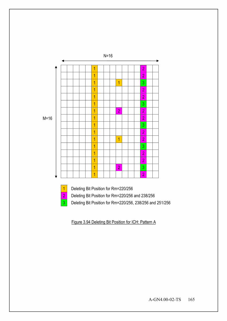
A-GN4.00-02-TS 165
Figure 3.94 Deleting Bit Position for ICH: Pattern A
1 2
1 2
1 1 3
1 2
1 2
1 3
1 2 2
1 2
1 3
1 2
1 1 2
1 3
1 2
1 2
1 2 3
1 2
1 Deleting Bit Position for Rm=220/256 2 Deleting Bit Position for Rm=220/256 and 238/256 3 Deleting Bit Position for Rm=220/256, 238/256 and 251/256
N=16
M=16

166 A-GN4.00-02-TS
Figure 3.95 Deleting Bit Position for ICH: Pattern B1
1 2
1 1 3
1 2
1 2
2 3
1 2
1 2
1 1 3
1 2
1 2
1 1 3
1 2
1 2
1 2 3
1 2
1 2
1 Deleting Bit Position for Rm=220/256 2 Deleting Bit Position for Rm=220/256 and 238/256 3 Deleting Bit Position for Rm=220/256, 238/256 and 251/256
N=16
M=16
A-GN4.00-02-TS 167
Figure 3.96 Deleting Bit Position of ICH: Pattern B2
1 2
1 2
1 2
1 2 3
1 2
1 2
1 1 3
1 2
1 2
1 1 3
1 2
1 2
2 3
1 2
1 2
1 1 3
1 Deleting Bit Position for Rm=220/256 2 Deleting Bit Position for Rm=220/256 and 238/256 3 Deleting Bit Position for Rm=220/256, 238/256 and 251/256
N=16
M=16
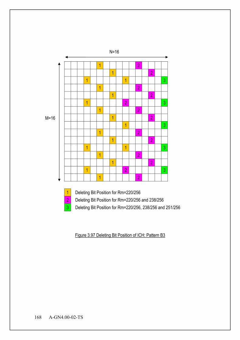
168 A-GN4.00-02-TS
Figure 3.97 Deleting Bit Position of ICH: Pattern B3
1 2 1 2 1 1 3 1 2 1 2 1 2 3 1 2 1 2 1 3 1 2 1 2 1 1 3 1 2 1 2 1 2 3 1 2
1 Deleting Bit Position for Rm=220/256 2 Deleting Bit Position for Rm=220/256 and 238/256 3 Deleting Bit Position for Rm=220/256, 238/256 and 251/256
N=16
M=16
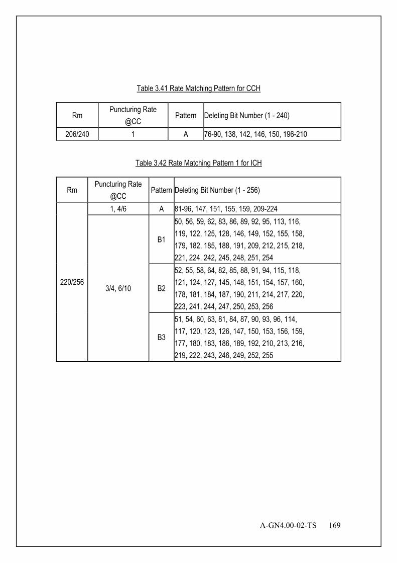
A-GN4.00-02-TS 169
Table 3.41 Rate Matching Pattern for CCH
Rm Puncturing Rate
@CC Pattern Deleting Bit Number (1 - 240)
206/240 1 A 76-90, 138, 142, 146, 150, 196-210
Table 3.42 Rate Matching Pattern 1 for ICH
Rm Puncturing Rate
@CC Pattern Deleting Bit Number (1 - 256)
220/256
1, 4/6 A 81-96, 147, 151, 155, 159, 209-224
3/4, 6/10
B1
50, 56, 59, 62, 83, 86, 89, 92, 95, 113, 116, 119, 122, 125, 128, 146, 149, 152, 155, 158, 179, 182, 185, 188, 191, 209, 212, 215, 218, 221, 224, 242, 245, 248, 251, 254
B2
52, 55, 58, 64, 82, 85, 88, 91, 94, 115, 118, 121, 124, 127, 145, 148, 151, 154, 157, 160, 178, 181, 184, 187, 190, 211, 214, 217, 220, 223, 241, 244, 247, 250, 253, 256
B3
51, 54, 60, 63, 81, 84, 87, 90, 93, 96, 114, 117, 120, 123, 126, 147, 150, 153, 156, 159, 177, 180, 183, 186, 189, 192, 210, 213, 216, 219, 222, 243, 246, 249, 252, 255
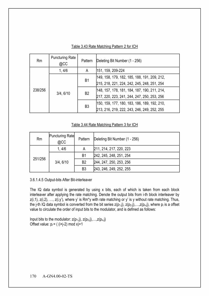
170 A-GN4.00-02-TS
Table 3.43 Rate Matching Pattern 2 for ICH
Rm Puncturing Rate
@CC Pattern Deleting Bit Number (1 - 256)
238/256
1, 4/6 A 151, 159, 209-224
3/4, 6/10
B1 149, 158, 179, 182, 185, 188, 191, 209, 212, 215, 218, 221, 224, 242, 245, 248, 251, 254
B2 148, 157, 178, 181, 184, 187, 190, 211, 214, 217, 220, 223, 241, 244, 247, 250, 253, 256
B3 150, 159, 177, 180, 183, 186, 189, 192, 210, 213, 216, 219, 222, 243, 246, 249, 252, 255
Table 3.44 Rate Matching Pattern 3 for ICH
Rm Puncturing Rate
@CC Pattern Deleting Bit Number (1 - 256)
251/256
1, 4/6 A 211, 214, 217, 220, 223
3/4, 6/10 B1 242, 245, 248, 251, 254 B2 244, 247, 250, 253, 256 B3 243, 246, 249, 252, 255
3.6.1.4.5 Output-bits After Bit-interleaver The IQ data symbol is generated by using x bits, each of which is taken from each block interleaver after applying the rate matching. Denote the output bits from i-th block interleaver by z(i,1), z(i,2), …, z(i,y’), where y’ is Rm*y with rate matching or y’ is y without rate matching. Thus, the j-th IQ data symbol is converted from the bit series z(p1,j), z(p2,j),…,z(px,j), where pi is a offset value to circulate the order of input bits to the modulator, and is defined as follows: Input bits to the modulator: z(p1,j), z(p2,j),…,z(px,j) Offset value: pi = ( (i+j-2) mod x)+1
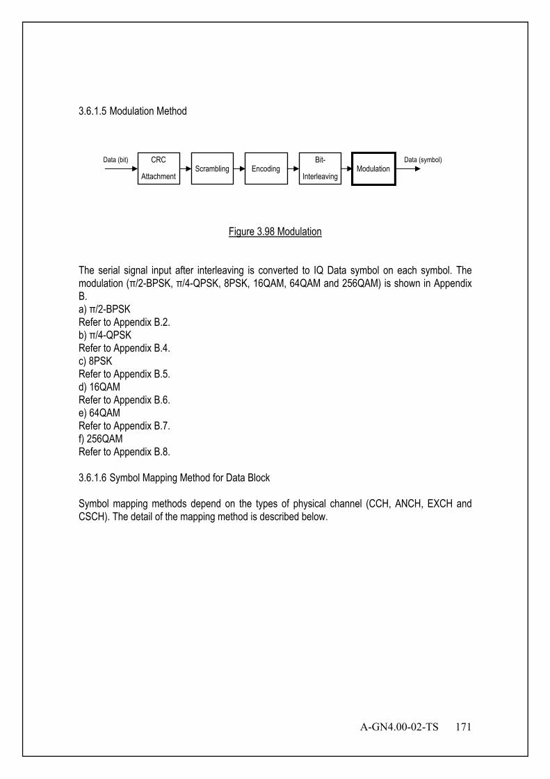
A-GN4.00-02-TS 171
3.6.1.5 Modulation Method
Figure 3.98 Modulation
The serial signal input after interleaving is converted to IQ Data symbol on each symbol. The modulation (π/2-BPSK, π/4-QPSK, 8PSK, 16QAM, 64QAM and 256QAM) is shown in Appendix B. a) π/2-BPSK Refer to Appendix B.2. b) π/4-QPSK Refer to Appendix B.4. c) 8PSK Refer to Appendix B.5. d) 16QAM Refer to Appendix B.6. e) 64QAM Refer to Appendix B.7. f) 256QAM Refer to Appendix B.8. 3.6.1.6 Symbol Mapping Method for Data Block Symbol mapping methods depend on the types of physical channel (CCH, ANCH, EXCH and CSCH). The detail of the mapping method is described below.
CRC
Attachment Scrambling Encoding
Bit-
Interleaving Modulation
Data (bit) Data (symbol)
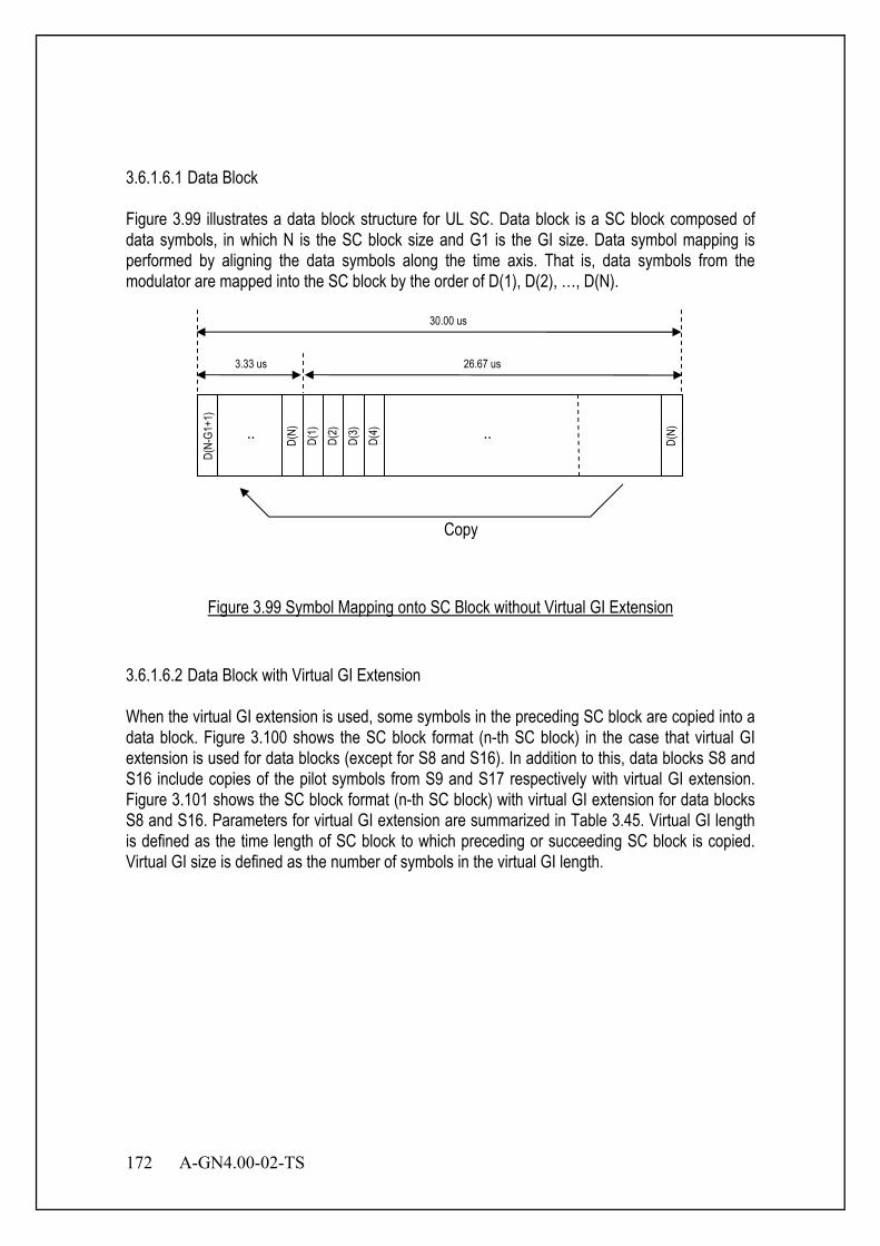
172 A-GN4.00-02-TS
3.6.1.6.1 Data Block Figure 3.99 illustrates a data block structure for UL SC. Data block is a SC block composed of data symbols, in which N is the SC block size and G1 is the GI size. Data symbol mapping is performed by aligning the data symbols along the time axis. That is, data symbols from the modulator are mapped into the SC block by the order of D(1), D(2), …, D(N).
Figure 3.99 Symbol Mapping onto SC Block without Virtual GI Extension
3.6.1.6.2 Data Block with Virtual GI Extension When the virtual GI extension is used, some symbols in the preceding SC block are copied into a data block. Figure 3.100 shows the SC block format (n-th SC block) in the case that virtual GI extension is used for data blocks (except for S8 and S16). In addition to this, data blocks S8 and S16 include copies of the pilot symbols from S9 and S17 respectively with virtual GI extension. Figure 3.101 shows the SC block format (n-th SC block) with virtual GI extension for data blocks S8 and S16. Parameters for virtual GI extension are summarized in Table 3.45. Virtual GI length is defined as the time length of SC block to which preceding or succeeding SC block is copied. Virtual GI size is defined as the number of symbols in the virtual GI length.
D(N-
G1+1
)
D(1)
D(
2)
D(3)
D(
4)
D(N)
.. D(N)
..
Copy
30.00 us
3.33 us 26.67 us

A-GN4.00-02-TS 173
Figure 3.100 Symbol Mapping of SC Block with Virtual GI Extension (Data Blocks Except for S8 and S16)
Figure 3.101 Symbol Mapping of SC Block with Virtual GI Extension (S8 and S16)
3.33 us 3.33 us GI
n-th SC Block
(n-1)-th SC Block
Virtual GI Length
26.67 us
26.67 us
Copy
(n+1)-th SC Block(Pilot Block) 26.67 us
Virtual GI Length 3.33 us
3.33 us 3.33 us GI
n-th SC Block
(n-1)-th SC Block
Virtual GI Length
26.67 us
26.67 us
Copy
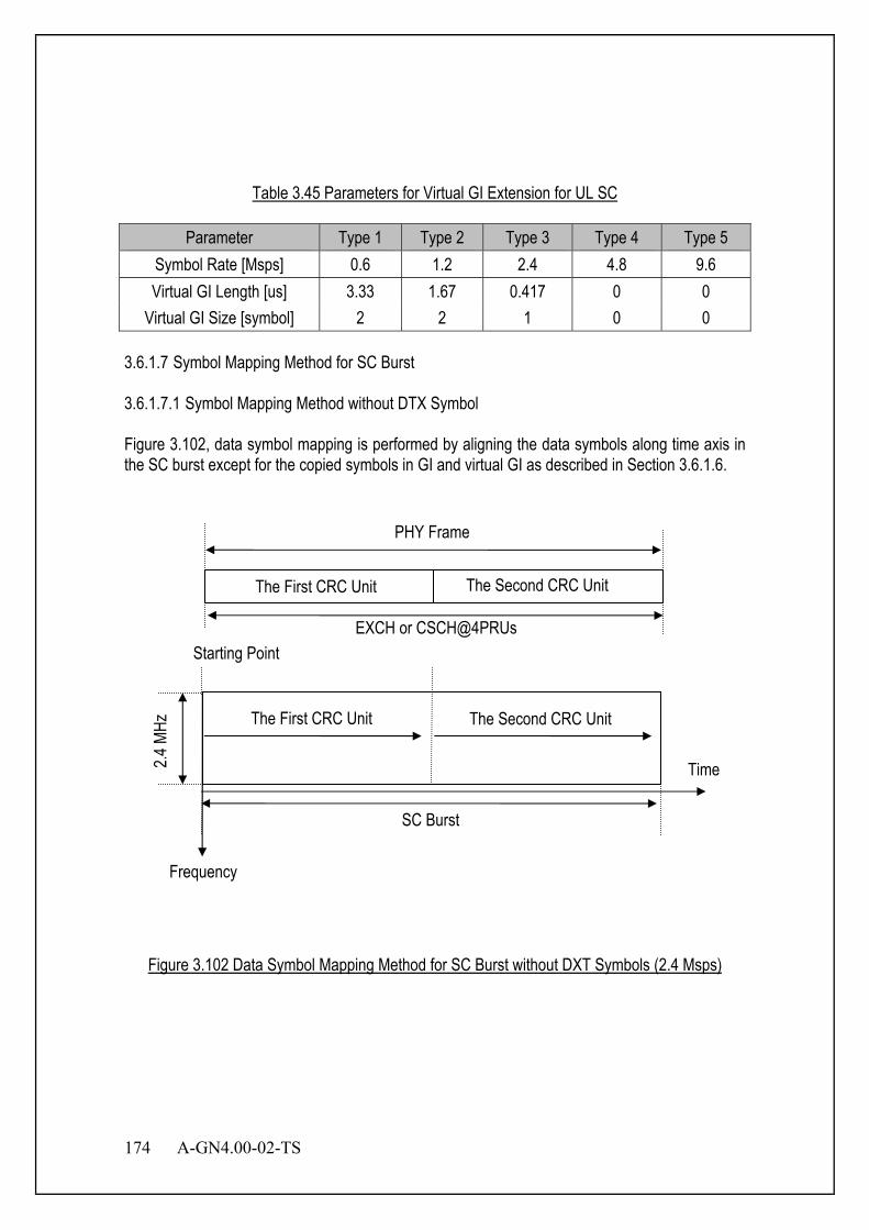
174 A-GN4.00-02-TS
Table 3.45 Parameters for Virtual GI Extension for UL SC
Parameter Type 1 Type 2 Type 3 Type 4 Type 5 Symbol Rate [Msps] 0.6 1.2 2.4 4.8 9.6 Virtual GI Length [us] 3.33 1.67 0.417 0 0
Virtual GI Size [symbol] 2 2 1 0 0 3.6.1.7 Symbol Mapping Method for SC Burst 3.6.1.7.1 Symbol Mapping Method without DTX Symbol Figure 3.102, data symbol mapping is performed by aligning the data symbols along time axis in the SC burst except for the copied symbols in GI and virtual GI as described in Section 3.6.1.6.
Figure 3.102 Data Symbol Mapping Method for SC Burst without DXT Symbols (2.4 Msps)
The First CRC Unit The Second CRC Unit
Starting Point
The First CRC Unit The Second CRC Unit
PHY Frame
2.4 M
Hz
SC Burst
Frequency
Time
EXCH or CSCH@4PRUs

A-GN4.00-02-TS 175
3.6.1.7.1.1 Symbol Mapping Method with DTX Symbol DTX symbol is used in EXCH and CSCH when the SC burst can accommodate more CRC units than the number of CRC units to be transmitted as shown in Figure 3.103. All data blocks after mapping all CRC units in the SC burst are DTX symbols. Details of DTX symbol are described in Section 3.6.5.
Figure 3.103 Data Symbol Mapping Method for SC Burst with DTX Symbols (2.4 Msps)
3.6.1.7.2 Symbol Mapping Method for Retransmission (CC-HARQ) Figure 3.104 to Figure 3.106 illustrate the retransmission of CRC unit, in which retransmission CRC unit size is equal to, smaller than or larger than the available CRC unit size for retransmission respectively.
The First CRC Unit
Starting Point
The first CRC Unit DTX
PHY Frame
2.4 M
Hz
SC Burst
Frequency
Time
EXCH or CSCH@4PRUs
DTX
DTX symbols are inserted to data blocks.
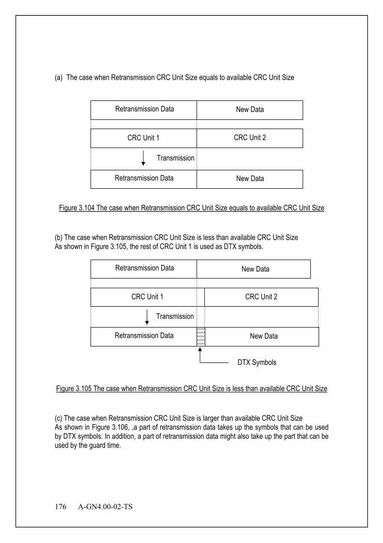
176 A-GN4.00-02-TS
(a) The case when Retransmission CRC Unit Size equals to available CRC Unit Size
Figure 3.104 The case when Retransmission CRC Unit Size equals to available CRC Unit Size
(b) The case when Retransmission CRC Unit Size is less than available CRC Unit Size As shown in Figure 3.105, the rest of CRC Unit 1 is used as DTX symbols.
Figure 3.105 The case when Retransmission CRC Unit Size is less than available CRC Unit Size
(c) The case when Retransmission CRC Unit Size is larger than available CRC Unit Size As shown in Figure 3.106, ,a part of retransmission data takes up the symbols that can be used by DTX symbols. In addition, a part of retransmission data might also take up the part that can be used by the guard time.
CRC Unit 1
Retransmission Data New Data
Retransmission Data New Data
DTX Symbols
Transmission
CRC Unit 2
CRC Unit 1 CRC Unit 2
Retransmission Data New Data
Retransmission Data New Data
Transmission

A-GN4.00-02-TS 177
Figure 3.106 The case when Retransmission CRC Unit Size is larger than available CRC Unit Size
3.6.1.8 Summary of SC UL Channel Coding Combinations of coding and modulation are shown in Table 3.46 for UL SC. Efficiency of each combination is shown in the same table. Efficiency is defined as the number of information bits carried by one data symbol in the SC burst. Efficiency and total coding rate are calculated assuming no virtual GI extension in the table. Note that actual efficiency becomes higher with virtual GI extension.
Retransmission Data New Data
Retransmission Data
DTX Symbols (Null)
Transmission
Retransmission Data New Data
CRC Unit 1 CRC Unit 2
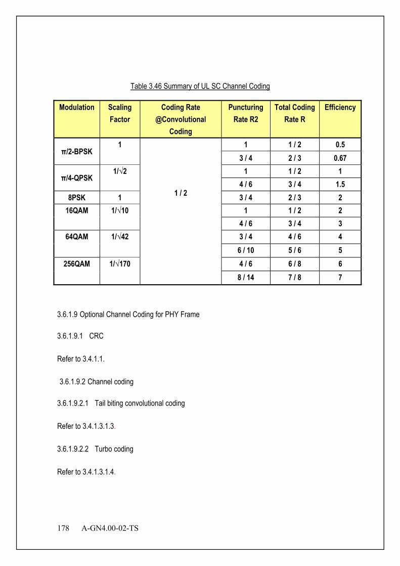
178 A-GN4.00-02-TS
Table 3.46 Summary of UL SC Channel Coding
Modulation Scaling Factor
Coding Rate @Convolutional
Coding
Puncturing Rate R2
Total Coding Rate R
Efficiency
π/2-BPSK 1
1 / 2
1 1 / 2 0.5 3 / 4 2 / 3 0.67
π/4-QPSK 1/√2 1 1 / 2 1
4 / 6 3 / 4 1.5 8PSK 1 3 / 4 2 / 3 2
16QAM 1/√10 1 1 / 2 2 4 / 6 3 / 4 3
64QAM 1/√42 3 / 4 4 / 6 4 6 / 10 5 / 6 5
256QAM 1/√170 4 / 6 6 / 8 6 8 / 14 7 / 8 7
3.6.1.9 Optional Channel Coding for PHY Frame 3.6.1.9.1 CRC Refer to 3.4.1.1. 3.6.1.9.2 Channel coding
3.6.1.9.2.1 Tail biting convolutional coding Refer to 3.4.1.3.1.3. 3.6.1.9.2.2 Turbo coding Refer to 3.4.1.3.1.4.

A-GN4.00-02-TS 179
3.6.1.9.3 Rate matching
Refer to 3.4.1.4.5
3.6.1.9.4 Code block concatenation The code block concatenation consists of sequentially concatenating the rate matching outputs for the different code blocks. 3.6.1.9.5 Channel Coding of UL Channels 3.6.1.9.5.1 Coding of data and control information on AUEDCH Data arrives to the coding unit in the form of a maximum of one transport block every transmission time interval (TTI). The following coding steps for the AUEDCH can be identified:
− Add CRC to the transport block
− Code block segmentation and code block CRC attachment
− Channel coding of data and control information
− Rate matching
− Code block concatenation
− Multiplexing of data and control information
− Channel interleaver
Control data arrives at the coding unit in the form of channel quality information (CQI and/or PMI), HARQ-ACK and rank indication. Different coding rates for the control information are achieved by allocating different number of coded symbols for its transmission. When control data are transmitted in the AUEDCH, the channel coding for HARQ-ACK, rank indication and channel quality information is done independently. 3.6.1.9.5.2 Coding of Uplink control information on AUANCH Data arrives to the coding unit in the form of indicators for measurement indication, scheduling request and HARQ acknowledgement. Three forms of channel coding are used, one for the channel quality information CQI/PMI, another for HARQ-ACK (acknowledgement) and scheduling
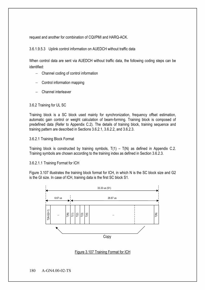
180 A-GN4.00-02-TS
request and another for combination of CQI/PMI and HARQ-ACK. 3.6.1.9.5.3 Uplink control information on AUEDCH without traffic data When control data are sent via AUEDCH without traffic data, the following coding steps can be identified:
− Channel coding of control information
− Control information mapping
− Channel interleaver
3.6.2 Training for UL SC Training block is a SC block used mainly for synchronization, frequency offset estimation, automatic gain control or weight calculation of beam-forming. Training block is composed of predefined data (Refer to Appendix C.2). The details of training block, training sequence and training pattern are described in Sections 3.6.2.1, 3.6.2.2, and 3.6.2.3. 3.6.2.1 Training Block Format Training block is constructed by training symbols, T(1) – T(N) as defined in Appendix C.2. Training symbols are chosen according to the training index as defined in Section 3.6.2.3. 3.6.2.1.1 Training Format for ICH Figure 3.107 illustrates the training block format for ICH, in which N is the SC block size and G2 is the GI size. In case of ICH, training data is the first SC block S1.
Figure 3.107 Training Format for ICH
T(N-
G2+1
)
T(1)
T(
2)
T(3)
T(
4)
T(N)
.. T(N)
..
Copy
33.33 us (S1)
6.67 us 26.67 us

A-GN4.00-02-TS 181
3.6.2.1.2 Training Format for CCCH Figure 3.108 illustrates the training format for CCCH. In case of CCCH, two training blocks S1 and S2 are used. Training symbols, T(1) – T(16), are mapped into S1 and S2 so that the training sequence repeats itself during the two SC blocks (S1 and S2) as shown in the figure.
Figure 3.108 Training format for CCH
3.6.2.2 Training Sequence Refer to Appendix C.2 for training sequence and offset values. Eight core-sequences are defined in Table C.5 to Table C.10. These core-sequences are on the constellation of 8PSK or 16PSK as shown in Appendix B.5 or Appendix B.9. In addition to these core-sequences, cyclic-shifted versions of them are also used for constructing training for ICH and CCH as shown in Table C.12. 3.6.2.3 Training Index As described in Section 3.6.2.2, there are 8 core-sequences and offset values (cyclic-shift values). Training index is numbered as follows: Training Index = Core-sequence Number + (Offset Value Number-1)*8 3.6.2.3.1 Training Index for CCCH Training index, core-sequence number and offset value number for CCH are defined as follows: Training Index : 2 Core-sequence Number : 2 Offset Value Number : 1
Copy
33.33 us (S1) 30.00 us (S2)
T(11
) T(
12)
T(13
) T(
14)
T(15
) T(
16)
T(1)
T(
2)
T(3)
T(
4)
T(5)
T(
6)
T(7)
T(
8)
T(9)
T(
10)
T(11
) T(
12)
T(13
) T(
14)
T(15
) T(
16)
T(1)
T(
2)
T(3)
T(
4)
T(5)
T(
6)
T(7)
T(
8)
T(9)
T(
10)
T(11
) T(
12)
T(13
) T(
14)
T(15
) T(
16)
10.00 us 53.33 us
Training Sequence Training Sequence

182 A-GN4.00-02-TS
3.6.2.3.2 Training Index for ICH ICH is composed of ANCH, EXCH and CSCH. Training index, core-sequence number and offset value number for ICH are defined as follows: Training Index : x + (y-1)*8 Core-sequence Number : x=[A MOD 8]+ 1 Offset Value Number : y=[{B+m} MOD (n-1)]+ 2 n = maximum number of SCHs in a slot m = the smallest SCH number assigned to the MS in the slot (m=1,2,3,…) A = 1st to 5th bits including LSB in BSID B = 1st to 5th bits next to A in BSID Training index, core-sequence number and offset value number for MIMO are defined as follows: Training Index : x + (y-1)*8 Core-sequence Number : x=[{A+k-1} MOD 8]+ 1 Offset Value Number : y=[{B+m} MOD (n-1)]+ 2 k =MIMO stream number (k=1,2,…) n = maximum number of SCHs in a slot m = the smallest SCH number assigned to the MS in the slot (m=1,2,3,…) A = 1st to 5th bits including LSB in BSID B = 1st to 5th bits next to A in BSID 3.6.3 Pilot for UL SC Figure 3.109 illustrates a pilot block format. Pilot block is a SC block used mainly for channel estimation. Pilot block consists of N pilot symbols, P(1) – P(N), as shown in this figure.
Figure 3.109 Pilot Block Format
P(N-
G1+1
)
P(1)
P(
2)
P(3)
P(
4)
P(N)
.. P(N)
..
Copy
30.00 us (S9 and S17)
3.33 us 26.67 us
A-GN4.00-02-TS 183
3.6.3.1 Pilot Index Pilot index is defined by eight core-sequences and offset values (cyclic-shift value) in the same way as training index described in Section 3.6.2.3. Pilot index is numbered as follows: Pilot index = core-sequence number + (offset value number-1)*8 3.6.3.2 Pilot for CCCH SC burst for CCCH has two pilot blocks at S9 and S17. Pilot block consists of 16 pilot symbols. Pilot symbols P(1) – P(16) in the both pilot blocks (S9 and S17) are the same as training symbols T(1) – T(16) in the training block S2 respectively. Pilot index is the same as training index in the same SC burst. 3.6.3.3 Pilot for ICH 3.6.3.3.1 Pilot for ANCH SC burst for ANCH has two pilot blocks at S9 and S17. Pilot block consists of 16 pilot symbols. Pilot symbols P(1) – P(16) in both pilot blocks (S9 and S17) are the same as training symbols T(1) – T(16) in the training block S1 correspondingly. Pilot index is the same as training index in the same SC burst. 3.6.3.3.2 Pilot for EXCH SC burst for EXCH has two pilot blocks at S9 and S17. Pilot block consists of 16 pilot symbols. Pilot symbols P(1) – P(N) in the both pilot blocks (S9 and S17) are the same as training symbols T(1) – T(N) in the training block S1 correspondingly. Pilot index is the same as training index in the same SC burst.

184 A-GN4.00-02-TS
3.6.3.3.3 Pilot for CSCH SC burst for CSCH has two pilot blocks at S9 and S17. Pilot symbols P(1) – P(N) in the pilot block S17 are the same as training symbols T(1) – T(N) in the training block S1 correspondingly. Pilot block S9 is different from as S17 for CSCH. For the symbol rate of 0.6 Msps (N=16), pilot symbols P(1) – P(N) in S9 are selected from Table C.5 in Appendix C.2 with the same pilot index. For 1.2 Msps and above (N>=32), pilot symbols in S9 are constructed by repeating the pilot block of half-length (N/2) with the same pilot index twice. Pilot block S9 is then modulated in order to multiplex signaling bits as described in Section 3.6.4.2. 3.6.3.4 Advanced Optional Pilot Signals Two types of uplink pilot signals are supported:
- Advanced Demodulation Pilot Signal, associated with transmission of AUEDCH or AUANCH
- Advanced Sounding Pilot Signal
The same set of base sequences is used for Advanced Demodulation Pilot Signal and Advanced Sounding Pilot Signals. Pilot signal sequence )()(
, nr vuα is defined by a cyclic shift α of a base sequence )(, nr vu
according to Pilotsc,
)(, 0),()( Mnnrenr vu
njvu <≤= αα ,where RU
scPilotsc mNM = is the length of the
trainning signal sequence and ULmax,RU1 Nm ≤≤ . Multiple pilot signal sequences are defined from a
single base sequence through different values of α . Base sequences )(, nr vu are divided into groups, where { }29,...,1,0∈u is the group number and v is the base sequence number within the group, such that each group contains one base sequence ( 0=v ) of each length RU
scPilotsc mNM = , 51 ≤≤ m and two base sequences ( 1,0=v )
of each length RUsc
Pilotsc mNM = , ULmax,
RU6 Nm ≤≤ . The definition of the base sequence )1(),...,0( Pilot
sc,, −Mrr vuvu depends on the sequence length PilotscM .
3.6.3.4.1 Advanced Demodulation Pilot signal 3.6.3.4.1.1 Advanced Demodulation Pilot signal sequence The aAdvanced Demodulation Pilot Signal sequence ( )⋅AUEDCHr for AUEDCH is defined
by ( ) ( )nrnMmr vu)(
,Pilotsc
AUEDCH α=+⋅ , where 1,0=m ; 1,...,0 Pilotsc −= Mn and AUEDCH
scRSsc MM = .
The aAdvanced Demodulation Pilot Signal sequence ( )⋅AUANCHr for AUANCH is defined by ( ) ( )nrmzmwnmMMNmr vu
)(,
Pilotsc
Pilotsc
AUANCHPilot
AUANCH )()(' α=++

A-GN4.00-02-TS 185
where 1,...,0 AUANCHPilot −= Nm , 1,...,0 Pilot
sc −= Mn and 1,0'=m .For CQICH, )(mz equals
)10(d for 1=m . For all other cases, .1)( =mz 3.6.3.4.1.2 Mapping to physical resources The sequence ( )⋅AUEDCHr shall be multiplied with the amplitude scaling factor AUEDCHβ and mapped in sequence starting with )0(AUEDCHr to the same set of physical resource blockunits used for the corresponding AUEDCH transmission. 3.6.3.4.2 Advanced Sounding Pilot signal 3.6.3.4.2.1 Advanced Souding Pilot signal sequence The aAdvanced Sounding Pilot signal sequence ( ) ( )nrnr vu
)(,
SP α= ,where u is the AUANCH sequence-group number and ν is the base sequence number. The cyclic shift α of the
Advanced Sounding Pilot signal is given as 8
2csSPnπα = , where cs
SPn is configured for each MS
by higher layers and 7,6,5,4,3,2,1,0csATS =n .
The BS-specific slot configuration period SFCT and the BS-specific slot offset SFC∆ for the transmission of advanced Sounding Pilot signals are determined by the higher layers parameter SoundingPilot-SlotConfig. Advanced Sounding Pilot signal slots are the slots satisfying SFCSFCs mod2/ ∆∈Tn . Advanced Sounding Pilot signal is transmitted only in configured UL slots or USS. When SoundingPilot-SlotConfig is from 0 to 7, SFCT is 5 slots while SFCT is 10 slots for SoundingPilot-SlotConfig from 8 to 15. SFC∆ is {1}, {1,2}, {1,3}, {1,4}, {1,2,3}, {1,2,4}, {1,3,4}, {1,2,3,4}, {1,2,6}, {1,3,6}, {1,6,7}, {1,2,6,8}, {1,3,6,9}, {1,4,6,7} for SoundingPilot-SlotConfig from 0 to 13 respectively. 3.6.3.4.3 Mapping to physical resources For all slots other than special slots, the Advanced Sounding Pilot signal shall be transmitted in the last symbol of the slot. The sequence shall be multiplied with the amplitude scaling factor SRSβ in order to conform to the transmit power SRSP , and mapped in sequence starting with )0(SRSr to resource elements
),( lk according to
−=
=+ otherwise01,...,1,0)( SP
sc,SRS
SRS,2 0
blkk
Mkkra β
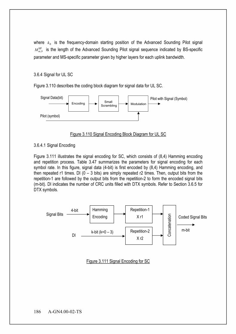
186 A-GN4.00-02-TS
where 0k is the frequency-domain starting position of the Advanced Sounding Pilot signal SPsc,bM is the length of the Advanced Sounding Pilot signal sequence indicated by BS-specific
parameter and MS-specific parameter given by higher layers for each uplink bandwidth. 3.6.4 Signal for UL SC Figure 3.110 describes the coding block diagram for signal data for UL SC.
Figure 3.110 Signal Encoding Block Diagram for UL SC
3.6.4.1 Signal Encoding Figure 3.111 illustrates the signal encoding for SC, which consists of (8,4) Hamming encoding and repetition process. Table 3.47 summarizes the parameters for signal encoding for each symbol rate. In this figure, signal data (4-bit) is first encoded by (8,4) Hamming encoding, and then repeated r1 times. DI (0 – 3 bits) are simply repeated r2 times. Then, output bits from the repetition-1 are followed by the output bits from the repetition-2 to form the encoded signal bits (m-bit). DI indicates the number of CRC units filled with DTX symbols. Refer to Section 3.6.5 for DTX symbols.
Figure 3.111 Signal Encoding for SC
Encoding Modulation
Pilot (symbol)
Pilot with Signal (Symbol) Small
Scrambling
Signal Data(bit)
Signal Bits Hamming Encoding
Repetition-1 X r1
4-bit Coded Signal Bits
Repetition-2 X r2
Conc
atena
tion
DI m-bit k-bit (k=0 – 3)
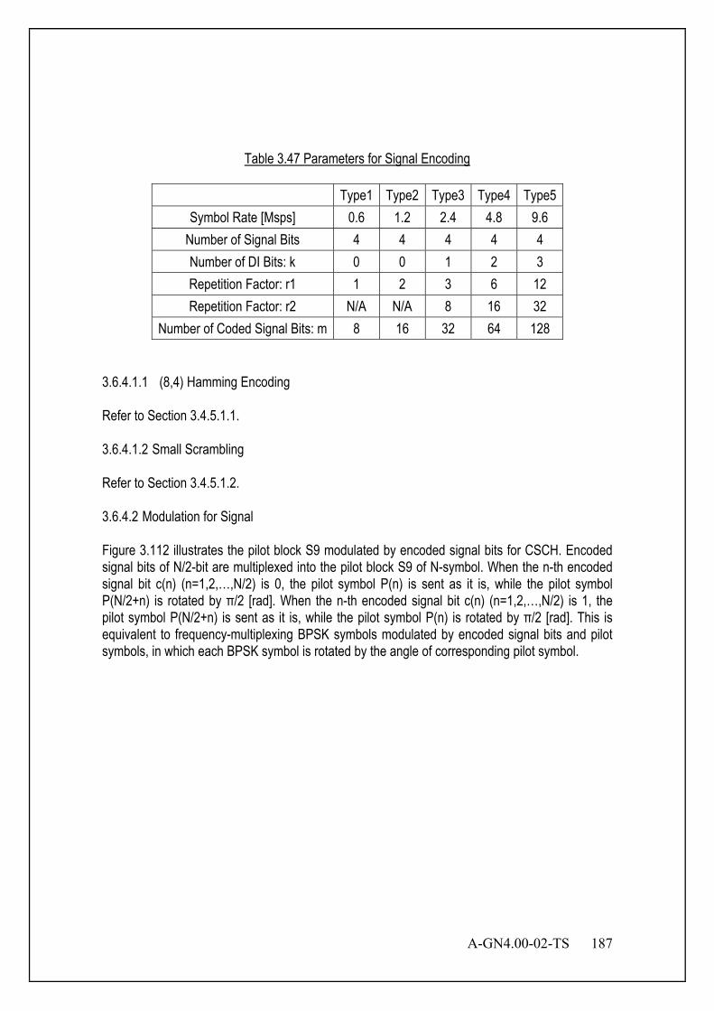
A-GN4.00-02-TS 187
Table 3.47 Parameters for Signal Encoding
Type1 Type2 Type3 Type4 Type5 Symbol Rate [Msps] 0.6 1.2 2.4 4.8 9.6
Number of Signal Bits 4 4 4 4 4 Number of DI Bits: k 0 0 1 2 3 Repetition Factor: r1 1 2 3 6 12 Repetition Factor: r2 N/A N/A 8 16 32
Number of Coded Signal Bits: m 8 16 32 64 128 3.6.4.1.1 (8,4) Hamming Encoding Refer to Section 3.4.5.1.1. 3.6.4.1.2 Small Scrambling Refer to Section 3.4.5.1.2. 3.6.4.2 Modulation for Signal Figure 3.112 illustrates the pilot block S9 modulated by encoded signal bits for CSCH. Encoded signal bits of N/2-bit are multiplexed into the pilot block S9 of N-symbol. When the n-th encoded signal bit c(n) (n=1,2,…,N/2) is 0, the pilot symbol P(n) is sent as it is, while the pilot symbol P(N/2+n) is rotated by π/2 [rad]. When the n-th encoded signal bit c(n) (n=1,2,…,N/2) is 1, the pilot symbol P(N/2+n) is sent as it is, while the pilot symbol P(n) is rotated by π/2 [rad]. This is equivalent to frequency-multiplexing BPSK symbols modulated by encoded signal bits and pilot symbols, in which each BPSK symbol is rotated by the angle of corresponding pilot symbol.

188 A-GN4.00-02-TS
Figure 3.112 Pilot Block with Signaling Bits for CSCH
3.6.5 Null (DTX) for UL SC Null symbol is defined as 0 + 0j. Null symbol is the same as DTX symbol. DTX symbol is used in EXCH and CSCH when the SC burst can accommodate more CRC units than the number of CRC units to be transmitted. All data blocks after mapping all CRC units in the SC burst are DTX symbols. When all data symbols in S8 or S16 are DTX symbols, symbols in the GI of S8 or S16 should be DTX symbols with or without virtual GI extension. Figure 3.113 shows the example of DTX symbol mapping for EXCH in case of 2.4 Msps, in which one CRC unit is to be transmitted.
30 us (S9)
3.33 us 26.67 us
Copy
P(N-
G1+1
) *ex
p(jπ
/2*(1
-c(N/
2-G1
+1)))
P(1)
*exp
(jπ/2*
c(1))
P(2)
*exp
(jπ/2*
c(2))
P(3)
*exp
(jπ/2*
c(3))
P(4)
*exp
(jπ/2*
c(4))
P(N)
*exp
(jπ/2*
(1-c(
N/2)
))
..
P(N)
*exp
(jπ/2*
(1-c(
N/2)
))
..
P(N/
2+1)
*exp
(jπ/2*
(1-c(
1)))
P(N/
2) *e
xp(jπ
/2*c(N
/2))
1 2 3 4 N/2 N/2+1 N .. ..
..

A-GN4.00-02-TS 189
Figure 3.113 DTX Symbol Mapping Method for EXCH (In case of 2.4 Msps)
3.6.6 TCCH for UL SC 3.6.6.1.1 TCCH Format TCCH is used mainly for transmission timing adjustment and for initial access to BS. Figure 3.114 shows the TCCH format. TCCH is composed of 3 consecutive SC blocks. TCCH symbols T(1) – T(16) are decided by the TCCH core-sequence number as explained in Section 3.6.6.2.
Figure 3.114 TCCH Block Structure
2.4 M
Hz
625 us
573.3 us
S1 S2 S3 S4 S5 S6 S7 S8 S9 S10 S11 S12 S13 S14 S15 S16 S17 S18 S19
Training Block Guard Time Pilot Block Data Block
DTX Block (Data Block with DTX Symbols)
SC Block a
T(11
) T(
12)
T(13
) T(
14)
T(15
) T(
16)
T(1)
T(
2)
T(3)
T(
4)
T(5)
T(
6)
T(7)
T(
8)
T(9)
T(
10)
T(11
) T(
12)
T(13
) T(
14)
T(15
) T(
16)
T(1)
T(
2)
T(3)
T(
4)
T(5)
T(
6)
T(7)
T(
8)
T(9)
T(
10)
T(11
) T(
12)
T(13
) T(
14)
T(15
) T(
16)
90.00 us
Training Sequence Training Sequence
Copy
T(2)
T(
3)
T(4)
T(
5)
T(6)
T(
7)
T(8)
T(
9)
T(10
) T(
11)
T(12
) T(
13)
T(14
) T(
15)
T(16
)
T(1)
10.00 us Training Sequence
SC Block b SC Block c
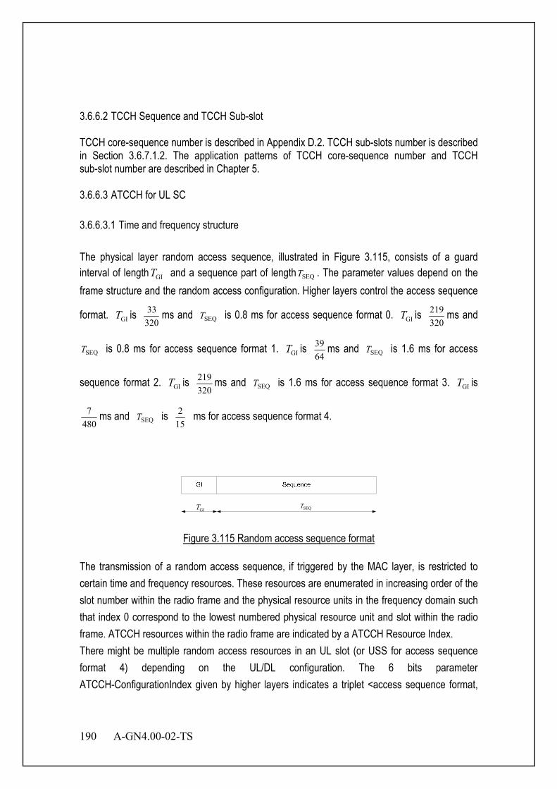
190 A-GN4.00-02-TS
3.6.6.2 TCCH Sequence and TCCH Sub-slot TCCH core-sequence number is described in Appendix D.2. TCCH sub-slots number is described in Section 3.6.7.1.2. The application patterns of TCCH core-sequence number and TCCH sub-slot number are described in Chapter 5. 3.6.6.3 ATCCH for UL SC 3.6.6.3.1 Time and frequency structure The physical layer random access sequence, illustrated in Figure 3.115, consists of a guard interval of length GIT and a sequence part of length SEQT . The parameter values depend on the frame structure and the random access configuration. Higher layers control the access sequence
format. GIT is 32033 ms and SEQT is 0.8 ms for access sequence format 0. GIT is
320219 ms and
SEQT is 0.8 ms for access sequence format 1. GIT is 6439 ms and SEQT is 1.6 ms for access
sequence format 2. GIT is 320219 ms and SEQT is 1.6 ms for access sequence format 3. GIT is
4807 ms and SEQT is
152 ms for access sequence format 4.
GIT SEQT
Figure 3.115 Random access sequence format
The transmission of a random access sequence, if triggered by the MAC layer, is restricted to certain time and frequency resources. These resources are enumerated in increasing order of the slot number within the radio frame and the physical resource units in the frequency domain such that index 0 correspond to the lowest numbered physical resource unit and slot within the radio frame. ATCCH resources within the radio frame are indicated by a ATCCH Resource Index. There might be multiple random access resources in an UL slot (or USS for access sequence format 4) depending on the UL/DL configuration. The 6 bits parameter ATCCH-ConfigurationIndex given by higher layers indicates a triplet <access sequence format,

A-GN4.00-02-TS 191
Density Per 10 ms ATCCHD , Version ATCCHr >, where access sequence format, ATCCHD and
ATCCHr are indicated by ATCCH-ConfigurationIndex value from 0 to 57 with mapping in sequence
to {0,0,0,0,0,0,0,0,0,0,0,0,0,0,0,0,0,0,0,1,1,1,1,1,1,1,1,1,1,2,2,2,2,2,2,2,2,2,2,3,3,3,3,3,3,3,3,4,4,4, 4,4,4,4,4,4,4}, {0.5,0.5,0.5,1,1,1,2,2,2,3,3,3,4,4,4,5,5,5,6,6,0.5,0.5,0.5,1,1,2,3,4,5,6,0.5,0.5,0.5, 1,1,2,3,4,5,6,0.5,0.5,0.5,1,1,2,3,4,0.5,0.5,0.5,1,1,2,3,4,5,6} and {0,1,2,0,1,2,0,1,2,0,1,2,0,1,2, 0,1,2,0,1,0,1,2,0,1,0,0,0,0,0,0,1,2,0,1,0,0,0,0,0,0,1,2,0,1,0,0,0, 0,1,2,0,1,0,0,0,0,0} respectively. The ATCCH opportunities are allocated in time first and then in frequency if and only if time multiplexing is not sufficient to hold all opportunities of a configuration without overlap in time. Then the location of random access resource for a certain ATCCH opportunity can be indicated
by time location triplet 210 ,, ATCCHATCCHATCCH ttt and frequency location ATCCHk .
For time location, 2,1,00 =ATCCHt indicates the random access resource is located in every, even
or odd radio frame, respectively; 1,01 =ATCCHt indicates the random access resource is located
in the first half frame or in the second half frame of a radio frame, respectively; and 2ATCCHt
counting from 0 at the first UL slot (for access sequence format 0 to 3) or at USS (for access sequence format 4) in a half frame, indicates which UL slot or USS the random access resource
starts from in a half frame. The time location triplet 210 ,, ATCCHATCCHATCCH ttt is given by
( )[ ] ( )[ ]
( ) ATCCH
indATCCH
ATCCHHFUL
slotATCCH
indATCCHATCCH
ATCCHATCCHATCCHATCCH
LmtNt
mt
dDrDt
+
−=
=
++=
12
2mod
2mod12mod2
1,2
1
0
where d is index of ATCCH opportunities and 10 −≤≤ ATCCHDd , ( )iN HFULslot
, is the number of UL slots (for access sequence format 0 to 3) or USS (for access sequence format 4) in the 1st ( 0=i ) or the 2nd ( 1=i ) half frame, ATCCHL is the number of slots occupied by the access
sequence, which equals to 310)( ⋅+ SEQGI TT . For access sequence format 0 and 4<ATCCHD ,
indATCCHm is defined by
( )
+
+=
2mod21 ATCCH
ATCCHATCCHindATCCH D
dDrm , otherwise
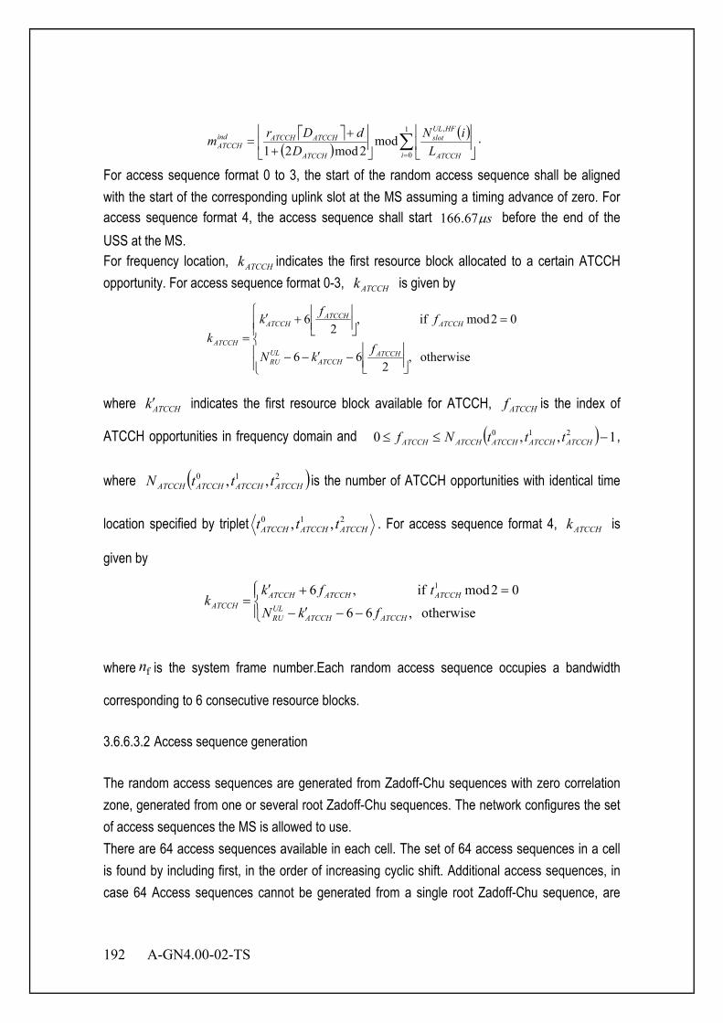
192 A-GN4.00-02-TS
( )
( )∑=
+
+=
1
0
,
mod2mod21 i ATCCH
HFULslot
ATCCH
ATCCHATCCHindATCCH L
iND
dDrm .
For access sequence format 0 to 3, the start of the random access sequence shall be aligned with the start of the corresponding uplink slot at the MS assuming a timing advance of zero. For access sequence format 4, the access sequence shall start sµ67.166 before the end of the USS at the MS. For frequency location, ATCCHk indicates the first resource block allocated to a certain ATCCH opportunity. For access sequence format 0-3, ATCCHk is given by
−′−−
=
+′
=otherwise ,
266
02mod if ,2
6
ATCCHATCCH
ULRU
ATCCHATCCH
ATCCH
ATCCH fkN
ffkk
where ATCCHk′ indicates the first resource block available for ATCCH, ATCCHf is the index of
ATCCH opportunities in frequency domain and ( ) 1,,0 210 −≤≤ ATCCHATCCHATCCHATCCHATCCH tttNf ,
where ( )210 ,, ATCCHATCCHATCCHATCCH tttN is the number of ATCCH opportunities with identical time
location specified by triplet 210 ,, ATCCHATCCHATCCH ttt . For access sequence format 4, ATCCHk is
given by
−−′−
=+′=
otherwise ,66
02mod if ,6 1
ATCCHATCCHULRU
ATCCHATCCHATCCHATCCH fkN
tfkk
where fn is the system frame number.Each random access sequence occupies a bandwidth
corresponding to 6 consecutive resource blocks. 3.6.6.3.2 Access sequence generation The random access sequences are generated from Zadoff-Chu sequences with zero correlation zone, generated from one or several root Zadoff-Chu sequences. The network configures the set of access sequences the MS is allowed to use. There are 64 access sequences available in each cell. The set of 64 access sequences in a cell is found by including first, in the order of increasing cyclic shift. Additional access sequences, in case 64 Access sequences cannot be generated from a single root Zadoff-Chu sequence, are
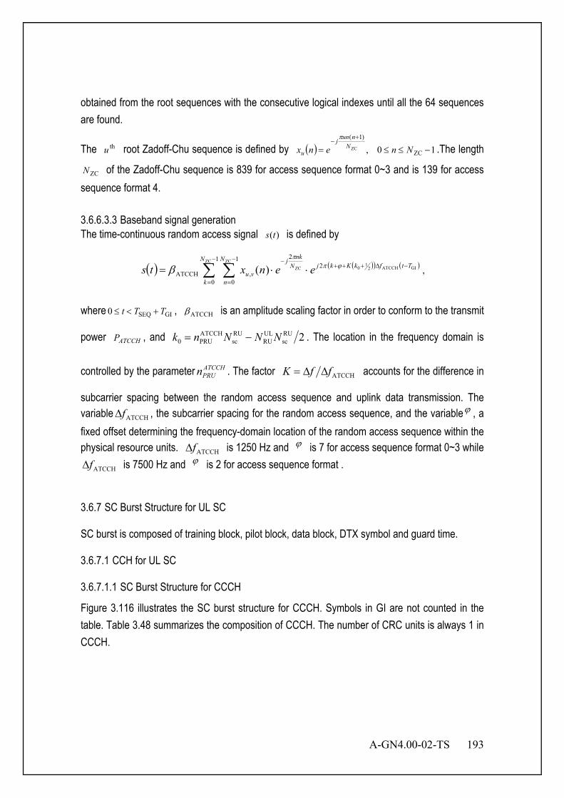
A-GN4.00-02-TS 193
obtained from the root sequences with the consecutive logical indexes until all the 64 sequences are found.
The thu root Zadoff-Chu sequence is defined by ( ) 10, ZC
)1(
ZC −≤≤=+
−Nnenx N
nunj
u
π
.The length
ZCN of the Zadoff-Chu sequence is 839 for access sequence format 0~3 and is 139 for access sequence format 4. 3.6.6.3.3 Baseband signal generation The time-continuous random access signal )(ts is defined by
( ) ( )( ) ( )∑ ∑−
=
−∆+++−
=
−
⋅⋅=1
0
21
0
2
,ATCCH
ZCGIATCCH2
10
ZCZC)(
N
k
TtfkKkjN
n
Nnkj
vu eenxts ϕππ
β ,
where GISEQ0 TTt +<≤ , ATCCHβ is an amplitude scaling factor in order to conform to the transmit
power ATCCHP , and 2RUsc
ULRU
RUsc
ATCCHPRU0 NNNnk −= . The location in the frequency domain is
controlled by the parameter ATCCHPRUn . The factor ATCCHffK ∆∆= accounts for the difference in
subcarrier spacing between the random access sequence and uplink data transmission. The variable ATCCHf∆ , the subcarrier spacing for the random access sequence, and the variableϕ , a fixed offset determining the frequency-domain location of the random access sequence within the physical resource units. ATCCHf∆ is 1250 Hz and ϕ is 7 for access sequence format 0~3 while
ATCCHf∆ is 7500 Hz and ϕ is 2 for access sequence format . 3.6.7 SC Burst Structure for UL SC SC burst is composed of training block, pilot block, data block, DTX symbol and guard time.
3.6.7.1 CCH for UL SC 3.6.7.1.1 SC Burst Structure for CCCH
Figure 3.116 illustrates the SC burst structure for CCCH. Symbols in GI are not counted in the table. Table 3.48 summarizes the composition of CCCH. The number of CRC units is always 1 in CCCH.
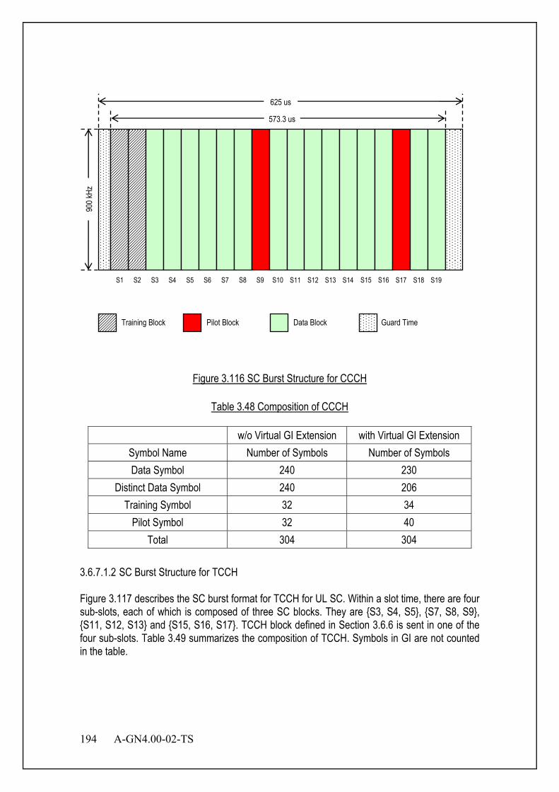
194 A-GN4.00-02-TS
Figure 3.116 SC Burst Structure for CCCH
Table 3.48 Composition of CCCH
w/o Virtual GI Extension with Virtual GI Extension Symbol Name Number of Symbols Number of Symbols Data Symbol 240 230
Distinct Data Symbol 240 206 Training Symbol 32 34
Pilot Symbol 32 40 Total 304 304
3.6.7.1.2 SC Burst Structure for TCCH Figure 3.117 describes the SC burst format for TCCH for UL SC. Within a slot time, there are four sub-slots, each of which is composed of three SC blocks. They are {S3, S4, S5}, {S7, S8, S9}, {S11, S12, S13} and {S15, S16, S17}. TCCH block defined in Section 3.6.6 is sent in one of the four sub-slots. Table 3.49 summarizes the composition of TCCH. Symbols in GI are not counted in the table.
900 k
Hz
625 us
573.3 us
S1 S2 S3 S4 S5 S6 S7 S8 S9 S10 S11 S12 S13 S14 S15 S16 S17 S18 S19
Training Block Guard Time Pilot Block Data Block
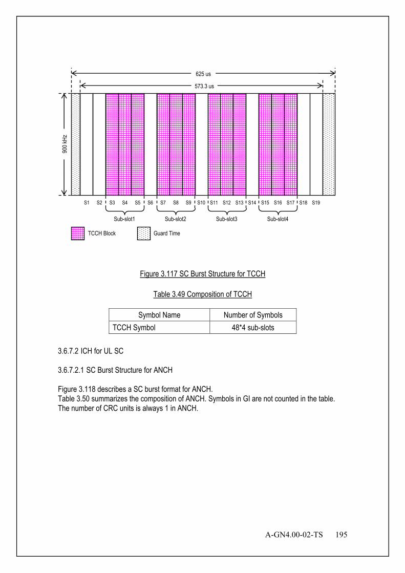
A-GN4.00-02-TS 195
Figure 3.117 SC Burst Structure for TCCH
Table 3.49 Composition of TCCH
Symbol Name Number of Symbols TCCH Symbol 48*4 sub-slots
3.6.7.2 ICH for UL SC 3.6.7.2.1 SC Burst Structure for ANCH Figure 3.118 describes a SC burst format for ANCH. Table 3.50 summarizes the composition of ANCH. Symbols in GI are not counted in the table. The number of CRC units is always 1 in ANCH.
900 k
Hz
625 us
573.3 us
S1 S2 S3 S4 S5 S6 S7 S8 S9 S10 S11 S12 S13 S14 S15 S16 S17 S18 S19
Sub-slot1 Sub-slot2 Sub-slot3 Sub-slot4
TCCH Block Guard Time

196 A-GN4.00-02-TS
Figure 3.118 SC Burst Structure for ANCH
Table 3.50 Composition of ANCH
w/o Virtual GI Extension with Virtual GI Extension Symbol Name Number of Symbols Number of Symbols Data Symbol 256 246
Distinct Data Symbol 256 220 Training Symbol 16 18
Pilot Symbol 32 40 Total 304 304
3.6.7.2.2 SC Burst Structure for EXCH Figure 3.119 illustrates a SC burst format for EXCH. Table 3.51 to Table 3.55 summarize the composition of EXCH for different symbol rates. Table 3.56 summarizes the composition of CRC unit in EXCH. Symbols in GI are not counted in these tables.
900 k
Hz
625 us
573.3 us
S1 S2 S3 S4 S5 S6 S7 S8 S9 S10 S11 S12 S13 S14 S15 S16 S17 S18 S19
Training Block Guard Time Pilot Block
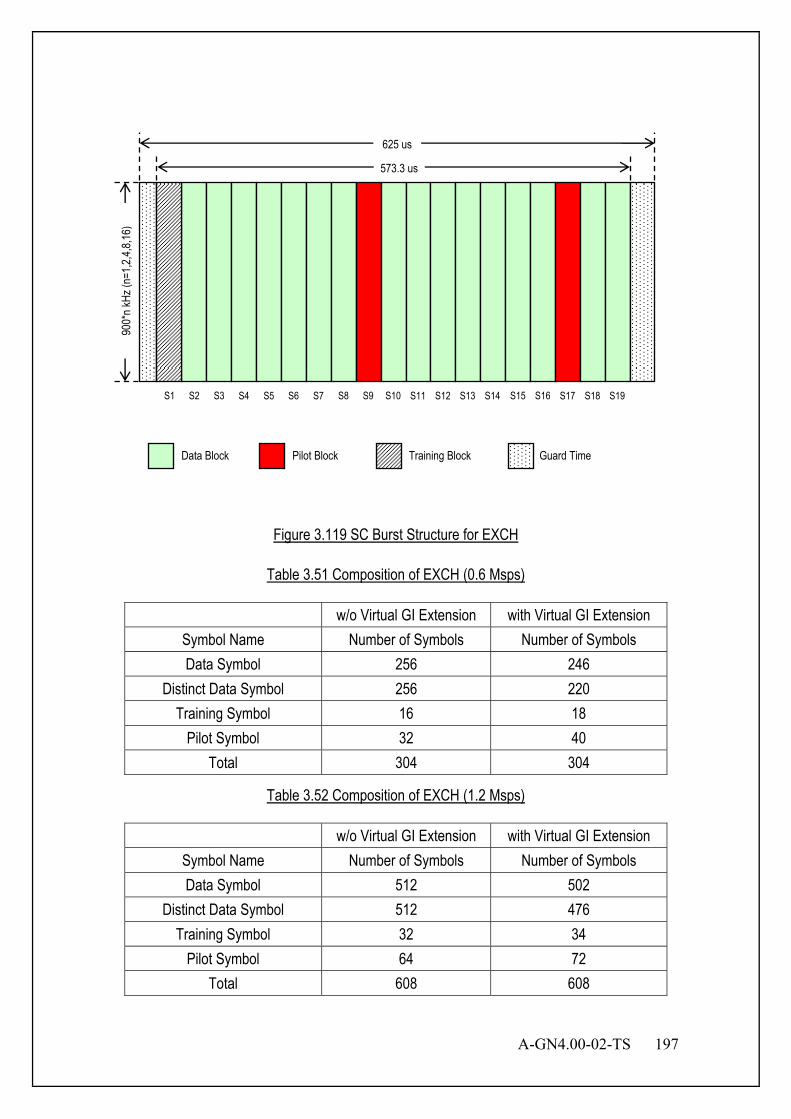
A-GN4.00-02-TS 197
Figure 3.119 SC Burst Structure for EXCH
Table 3.51 Composition of EXCH (0.6 Msps)
w/o Virtual GI Extension with Virtual GI Extension Symbol Name Number of Symbols Number of Symbols Data Symbol 256 246
Distinct Data Symbol 256 220 Training Symbol 16 18
Pilot Symbol 32 40 Total 304 304
Table 3.52 Composition of EXCH (1.2 Msps)
w/o Virtual GI Extension with Virtual GI Extension Symbol Name Number of Symbols Number of Symbols Data Symbol 512 502
Distinct Data Symbol 512 476 Training Symbol 32 34
Pilot Symbol 64 72 Total 608 608
900*
n kHz
(n=1
,2,4,8
,16)
625 us
573.3 us
S1 S2 S3 S4 S5 S6 S7 S8 S9 S10 S11 S12 S13 S14 S15 S16 S17 S18 S19
Training Block Guard Time Pilot Block Data Block

198 A-GN4.00-02-TS
Table 3.53 Composition of EXCH (2.4 Msps)
w/o Virtual GI Extension with Virtual GI Extension Symbol Name Number of Symbols Number of Symbols Data Symbol 1024 1019
Distinct Data Symbol 1024 1006 Training Symbol 64 65
Pilot Symbol 128 132 Total 1216 1216
Table 3.54 Composition of EXCH (4.8 Msps)
w/o Virtual GI Extension with Virtual GI Extension Symbol Name Number of Symbols Number of Symbols Data Symbol 2048 N/A
Distinct Data Symbol 2048 N/A Training Symbol 128 N/A
Pilot Symbol 256 N/A Total 2432 N/A
Table 3.55 Composition of EXCH (9.6 Msps)
w/o Virtual GI Extension with Virtual GI Extension Symbol Name Number of Symbols Number of Symbols Data Symbol 4096 N/A
Distinct Data Symbol 4096 N/A Training Symbol 256 N/A
Pilot Symbol 512 N/A Total 4864 N/A
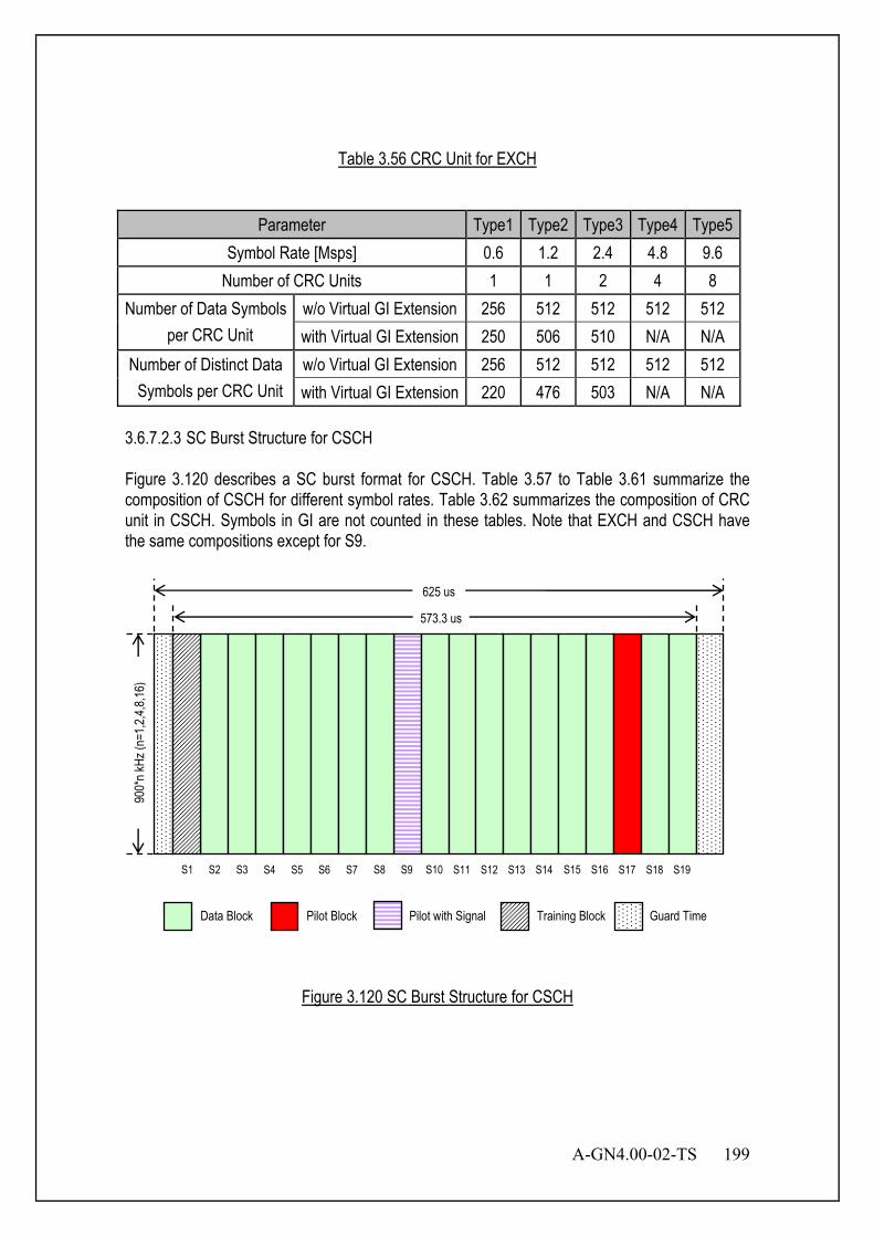
A-GN4.00-02-TS 199
Table 3.56 CRC Unit for EXCH
Parameter Type1 Type2 Type3 Type4 Type5
Symbol Rate [Msps] 0.6 1.2 2.4 4.8 9.6 Number of CRC Units 1 1 2 4 8
Number of Data Symbols per CRC Unit
w/o Virtual GI Extension 256 512 512 512 512 with Virtual GI Extension 250 506 510 N/A N/A
Number of Distinct Data Symbols per CRC Unit
w/o Virtual GI Extension 256 512 512 512 512 with Virtual GI Extension 220 476 503 N/A N/A
3.6.7.2.3 SC Burst Structure for CSCH Figure 3.120 describes a SC burst format for CSCH. Table 3.57 to Table 3.61 summarize the composition of CSCH for different symbol rates. Table 3.62 summarizes the composition of CRC unit in CSCH. Symbols in GI are not counted in these tables. Note that EXCH and CSCH have the same compositions except for S9.
Figure 3.120 SC Burst Structure for CSCH
900*
n kHz
(n=1
,2,4,8
,16)
625 us
573.3 us
S1 S2 S3 S4 S5 S6 S7 S8 S9 S10 S11 S12 S13 S14 S15 S16 S17 S18 S19
Guard Time Pilot Block Data Block Training Block Pilot with Signal
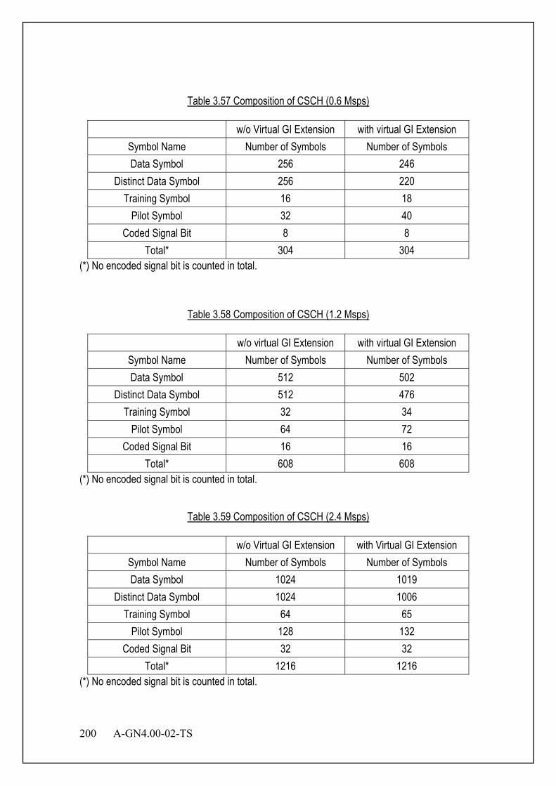
200 A-GN4.00-02-TS
Table 3.57 Composition of CSCH (0.6 Msps)
w/o Virtual GI Extension with virtual GI Extension Symbol Name Number of Symbols Number of Symbols Data Symbol 256 246
Distinct Data Symbol 256 220 Training Symbol 16 18
Pilot Symbol 32 40 Coded Signal Bit 8 8
Total* 304 304 (*) No encoded signal bit is counted in total.
Table 3.58 Composition of CSCH (1.2 Msps)
w/o virtual GI Extension with virtual GI Extension Symbol Name Number of Symbols Number of Symbols Data Symbol 512 502
Distinct Data Symbol 512 476 Training Symbol 32 34
Pilot Symbol 64 72 Coded Signal Bit 16 16
Total* 608 608 (*) No encoded signal bit is counted in total.
Table 3.59 Composition of CSCH (2.4 Msps)
w/o Virtual GI Extension with Virtual GI Extension Symbol Name Number of Symbols Number of Symbols Data Symbol 1024 1019
Distinct Data Symbol 1024 1006 Training Symbol 64 65
Pilot Symbol 128 132 Coded Signal Bit 32 32
Total* 1216 1216 (*) No encoded signal bit is counted in total.

A-GN4.00-02-TS 201
Table 3.60 Composition of CSCH (4.8 Msps)
w/o Virtual GI Extension with Virtual GI Extension Symbol Name Number of Symbols Number of Symbols Data Symbol 2048 N/A
Distinct Data Symbol 2048 N/A Training Symbol 128 N/A
Pilot Symbol 256 N/A Coded Signal Bit 64 N/A
Total* 2432 N/A (*) No encoded signal bit is counted in total.
Table 3.61 Composition of CSCH (9.6 Msps)
w/o Virtual GI Extension with Virtual GI Extension Symbol Name Number of Symbols Number of Symbols Data Symbol 4096 N/A
Distinct Data Symbol 4096 N/A Training Symbol 256 N/A
Pilot Symbol 512 N/A Coded Signal Bit 256 N/A
Total* 4864 N/A (*) No encoded signal bit is counted in total.
Table 3.62 CRC Unit for CSCH
Parameter Type1 Type2 Type3 Type4 Type5 Symbol Rate [Msps] 0.6 1.2 2.4 4.8 9.6
Number of CRC Units 1 1 2 4 8 Number of Data Symbols
per CRC Unit w/o Virtual GI Extension 256 512 512 512 512 with Virtual GI Extension 250 506 510 N/A N/A
Number of Distinct Data Symbols per CRC Unit
w/o Virtual GI Extension 256 512 512 512 512 with Virtual GI Extension 220 476 503 N/A N/A

202 A-GN4.00-02-TS
3.6.7.3 CRC Unit for UL SC Table 3.63 summarizes the CRC unit size for each symbol rate and channel format. In this table, CRC unit size means the number of bits in one CRC unit. Hence, the actual number of input bits to the CRC attachment (CRC unit) is 22-bit less than these numbers. Refer to the definition of CRC unit in Section 3.6.1.
Table 3.63 CRC Unit Size for UL SC
Modulation Total Coding Rate Efficiency Channel (*)
Symbol Rate [Msps] 0.6 1.2 2.4 4.8 9.6
π/2-BPSK 1 / 2 0.5 CC 120 N/A N/A N/A N/A 1 / 2 0.5 A,E,CS 128 256 256 256 256 2 / 3 0.67
E,CS
170 N/A N/A N/A N/A
π/4-QPSK 1 / 2 1 256 512 512 512 512 3 / 4 1.5 384 768 768 768 768
8PSK 2 / 3 2 512 1024 1024 1024 1024 16QAM 1 /2 2 512 1024 1024 1024 1024
3 / 4 3 768 1536 1536 1536 1536 64QAM 4 / 6 4 1024 2048 2048 2048 2048
5 / 6 5 1280 2560 2560 2560 2560 256QAM 6 / 8 6 1536 3072 3072 3072 3072
7 / 8 7 1792 3584 3584 3584 3584 (*) CC: CCCH, A: ANCH, E: EXCH, CS: CSCH 3.6.7.4 Transmission Timing of SC Burst for UL SC Transmission timing is controlled by the BS in ANCH as described in Chapter 4. Since the symbol rate of EXCH can be different from that of ANCH, relative transmission timing of SC burst should be changed according to the symbol rate and virtual GI extension size in order to minimize the inter-carrier interference at BS. Relative transmission timing of the target SC burst (EXCH) is calculated from the reference SC burst (ANCH) using the following equation. ∆ts = 0.5( g1-vg1-1)/r1- 0.5(g2-vg2-1)/r2. r1: Symbol rate of the reference SC burst g1: GI size of the reference SC burst vg1: Virtual GI size of the reference SC burst r2: Symbol rate of the target SC burst g2: GI size of the target SC burst
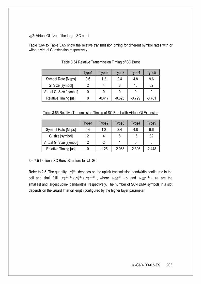
A-GN4.00-02-TS 203
vg2: Virtual GI size of the target SC burst Table 3.64 to Table 3.65 show the relative transmission timing for different symbol rates with or without virtual GI extension respectively.
Table 3.64 Relative Transmission Timing of SC Burst
Type1 Type2 Type3 Type4 Type5 Symbol Rate [Msps] 0.6 1.2 2.4 4.8 9.6
GI Size [symbol] 2 4 8 16 32 Virtual GI Size [symbol] 0 0 0 0 0
Relative Timing [us] 0 -0.417 -0.625 -0.729 -0.781
Table 3.65 Relative Transmission Timing of SC Burst with Virtual GI Extension
Type1 Type2 Type3 Type4 Type5 Symbol Rate [Msps] 0.6 1.2 2.4 4.8 9.6
GI size [symbol] 2 4 8 16 32 Virtual GI Size [symbol] 2 2 1 0 0
Relative Timing [us] 0 -1.25 -2.083 -2.396 -2.448 3.6.7.5 Optional SC Burst Structure for UL SC Refer to 2.5. The quantity UL
RUN depends on the uplink transmission bandwidth configured in the cell and shall fulfil ULmax,
RUULRU
ULmin,RU NNN ≤≤ , where 6ULmin,
RU =N and 110ULmax,RU =N are the
smallest and largest uplink bandwidths, respectively. The number of SC-FDMA symbols in a slot depends on the Guard Interval length configured by the higher layer parameter.
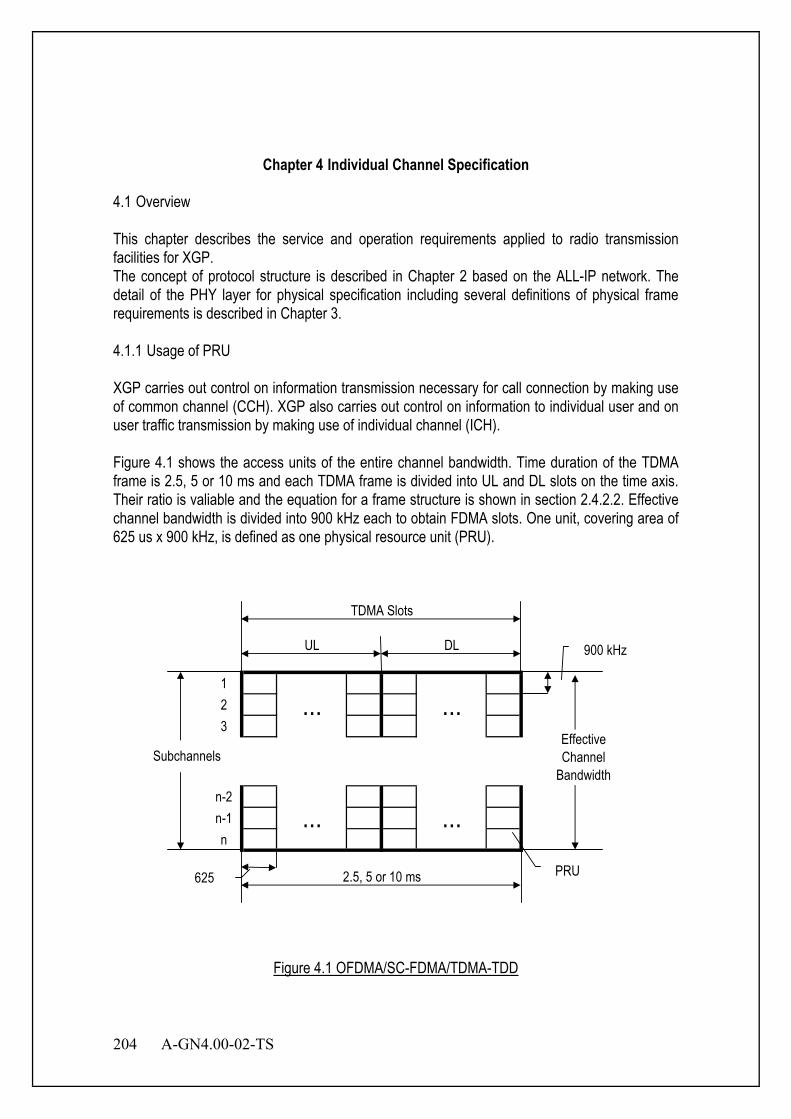
204 A-GN4.00-02-TS
Chapter 4 Individual Channel Specification
4.1 Overview This chapter describes the service and operation requirements applied to radio transmission facilities for XGP. The concept of protocol structure is described in Chapter 2 based on the ALL-IP network. The detail of the PHY layer for physical specification including several definitions of physical frame requirements is described in Chapter 3. 4.1.1 Usage of PRU XGP carries out control on information transmission necessary for call connection by making use of common channel (CCH). XGP also carries out control on information to individual user and on user traffic transmission by making use of individual channel (ICH). Figure 4.1 shows the access units of the entire channel bandwidth. Time duration of the TDMA frame is 2.5, 5 or 10 ms and each TDMA frame is divided into UL and DL slots on the time axis. Their ratio is valiable and the equation for a frame structure is shown in section 2.4.2.2. Effective channel bandwidth is divided into 900 kHz each to obtain FDMA slots. One unit, covering area of 625 us x 900 kHz, is defined as one physical resource unit (PRU).
123
n-2n-1n
2.5, 5 or 10 ms
UL DL
TDMA Slots
... ...
... ...
900 kHz
625
EffectiveChannel
Bandwidth
PRU
Subchannels
Figure 4.1 OFDMA/SC-FDMA/TDMA-TDD
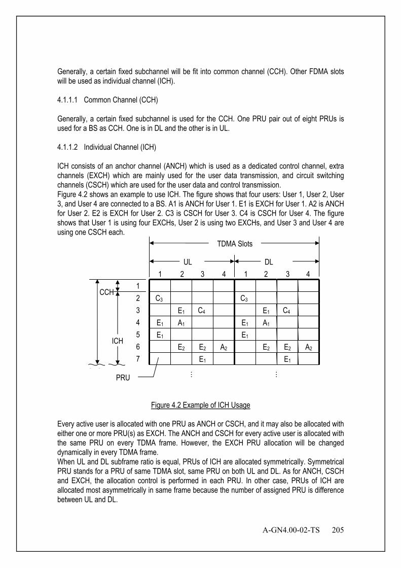
A-GN4.00-02-TS 205
Generally, a certain fixed subchannel will be fit into common channel (CCH). Other FDMA slots will be used as individual channel (ICH). 4.1.1.1 Common Channel (CCH) Generally, a certain fixed subchannel is used for the CCH. One PRU pair out of eight PRUs is used for a BS as CCH. One is in DL and the other is in UL. 4.1.1.2 Individual Channel (ICH) ICH consists of an anchor channel (ANCH) which is used as a dedicated control channel, extra channels (EXCH) which are mainly used for the user data transmission, and circuit switching channels (CSCH) which are used for the user data and control transmission. Figure 4.2 shows an example to use ICH. The figure shows that four users: User 1, User 2, User 3, and User 4 are connected to a BS. A1 is ANCH for User 1. E1 is EXCH for User 1. A2 is ANCH for User 2. E2 is EXCH for User 2. C3 is CSCH for User 3. C4 is CSCH for User 4. The figure shows that User 1 is using four EXCHs, User 2 is using two EXCHs, and User 3 and User 4 are using one CSCH each.
Figure 4.2 Example of ICH Usage
Every active user is allocated with one PRU as ANCH or CSCH, and it may also be allocated with either one or more PRU(s) as EXCH. The ANCH and CSCH for every active user is allocated with the same PRU on every TDMA frame. However, the EXCH PRU allocation will be changed dynamically in every TDMA frame. When UL and DL subframe ratio is equal, PRUs of ICH are allocated symmetrically. Symmetrical PRU stands for a PRU of same TDMA slot, same PRU on both UL and DL. As for ANCH, CSCH and EXCH, the allocation control is performed in each PRU. In other case, PRUs of ICH are allocated most asymmetrically in same frame because the number of assigned PRU is difference between UL and DL.
E1 E1
E1
E1
E1 E1
E1 A1 A1
E2 E2 E2 E2 A2 A2 E1
1 2 3 4 1 2 3 4 UL DL
TDMA Slots
1
3 2
ICH
PRU
…
…
4 5 6 7
C3 C3 C4 C4
CCH
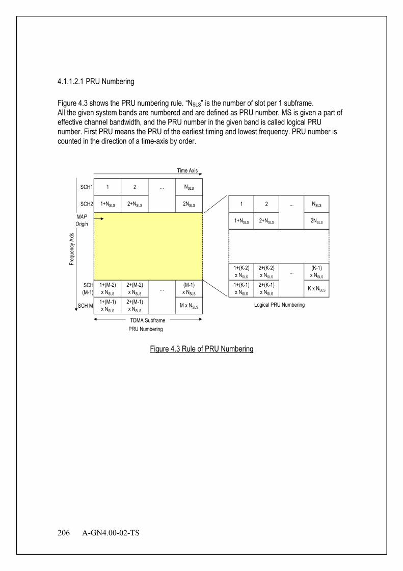
206 A-GN4.00-02-TS
4.1.1.2.1 PRU Numbering Figure 4.3 shows the PRU numbering rule. “NSLS” is the number of slot per 1 subframe. All the given system bands are numbered and are defined as PRU number. MS is given a part of effective channel bandwidth, and the PRU number in the given band is called logical PRU number. First PRU means the PRU of the earliest timing and lowest frequency. PRU number is counted in the direction of a time-axis by order.
SCH1 1 2 ... NSLS
SCH2 1+NSLS 2+NSLS 2NSLS 1 2 ... NSLS
1+NSLS 2+NSLS 2NSLS
1+(K-2)x NSLS
2+(K-2)x NSLS
... (K-1)x NSLS
SCH(M-1)
1+(M-2)x NSLS
2+(M-2)x NSLS
... (M-1)x NSLS
1+(K-1)x NSLS
2+(K-1)x NSLS
K x NSLS
SCH M 1+(M-1)x NSLS
2+(M-1)x NSLS
M x NSLS
Freq
uenc
y Axis
Time Axis
PRU Numbering
Logical PRU Numbering
MAPOrigin
TDMA Subframe
Figure 4.3 Rule of PRU Numbering
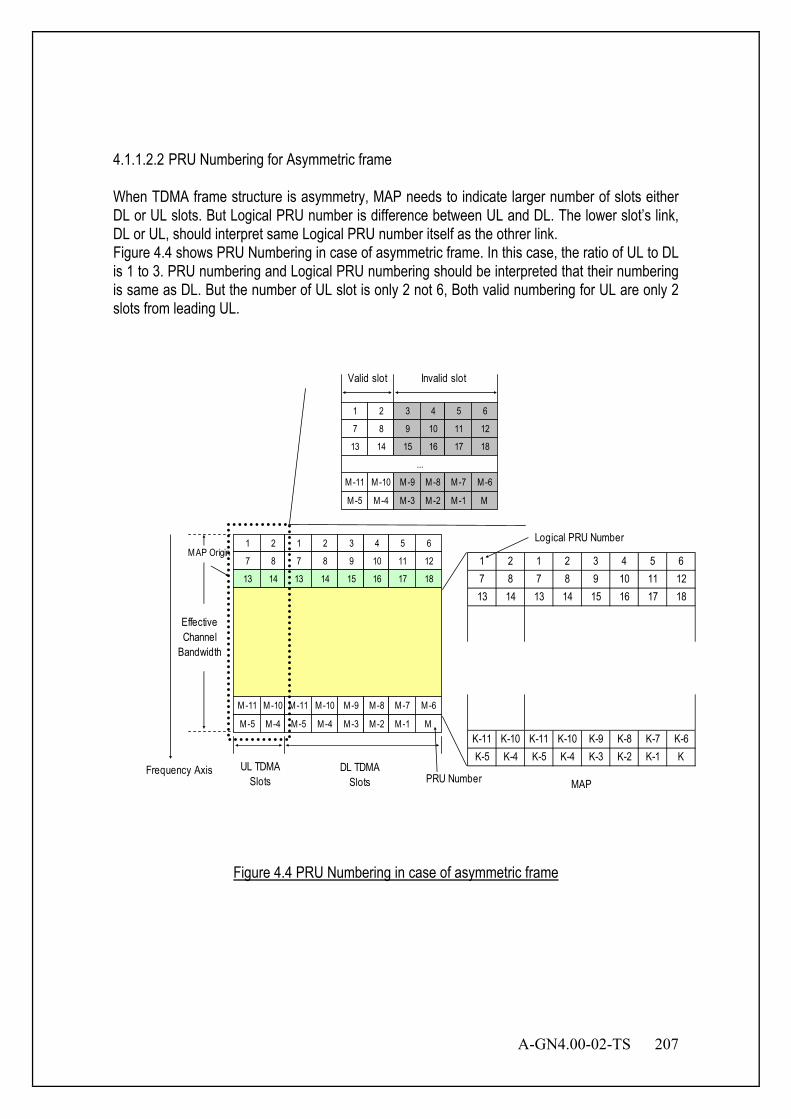
A-GN4.00-02-TS 207
4.1.1.2.2 PRU Numbering for Asymmetric frame When TDMA frame structure is asymmetry, MAP needs to indicate larger number of slots either DL or UL slots. But Logical PRU number is difference between UL and DL. The lower slot’s link, DL or UL, should interpret same Logical PRU number itself as the othrer link. Figure 4.4 shows PRU Numbering in case of asymmetric frame. In this case, the ratio of UL to DL is 1 to 3. PRU numbering and Logical PRU numbering should be interpreted that their numbering is same as DL. But the number of UL slot is only 2 not 6, Both valid numbering for UL are only 2 slots from leading UL.
1 2 1 2 3 4 5 67 8 7 8 9 10 11 1213 14 13 14 15 16 17 18
K-11 K-10 K-11 K-10 K-9 K-8 K-7 K-6K-5 K-4 K-5 K-4 K-3 K-2 K-1 K
MAPFrequency Axis
Logical PRU Number
PRU Number
EffectiveChannel
Bandwidth
DL TDMASlots
MAP Origin1 2 1 2
7 8 7 8
13 14 13 14
M-11 M-10 M-11 M-10
M-5 M-4 M-5 M-4
UL TDMASlots
3 4 5 6
9 10 11 12
15 16 17 18
M-9 M-8 M-7 M-6
M-3 M-2 M-1 M
1 2
7 8
13 14
M-11 M-10
M-5 M-4
3 4 5 6
9 10 11 12
15 16 17 18
M-9 M-8 M-7 M-6
M-3 M-2 M-1 M
...
Valid slot Invalid slot
Figure 4.4 PRU Numbering in case of asymmetric frame
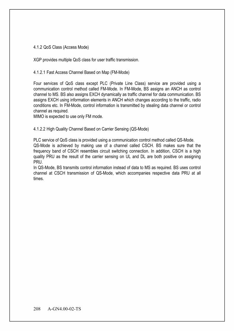
208 A-GN4.00-02-TS
4.1.2 QoS Class (Access Mode) XGP provides multiple QoS class for user traffic transmission. 4.1.2.1 Fast Access Channel Based on Map (FM-Mode) Four services of QoS class except PLC (Private Line Class) service are provided using a communication control method called FM-Mode. In FM-Mode, BS assigns an ANCH as control channel to MS. BS also assigns EXCH dynamically as traffic channel for data communication. BS assigns EXCH using information elements in ANCH which changes according to the traffic, radio conditions etc. In FM-Mode, control information is transmitted by stealing data channel or control channel as required. MIMO is expected to use only FM mode. 4.1.2.2 High Quality Channel Based on Carrier Sensing (QS-Mode) PLC service of QoS class is provided using a communication control method called QS-Mode. QS-Mode is achieved by making use of a channel called CSCH. BS makes sure that the frequency band of CSCH resembles circuit switching connection. In addition, CSCH is a high quality PRU as the result of the carrier sensing on UL and DL are both positive on assigning PRU. In QS-Mode, BS transmits control information instead of data to MS as required. BS uses control channel at CSCH transmission of QS-Mode, which accompanies respective data PRU at all times.

A-GN4.00-02-TS 209
4.1.3 XGP Protocol Outline 4.1.3.1 Frame Structure The frame of each layer consists of a header and one data unit or more. Table 4.1 shows the compositions of the PHY and MAC layer frame.
Table 4.1 Name of Frame Composition
Composition PHY Layer MAC Layer Frame PHY Frame MAC Frame Header PHY Header MAC Header
Data Unit PHY Data Unit MAC Data Unit Figure 4.5 shows the composition of the PHY and MAC layer frames. In each frame, a header is put at top of the frame, and is followed by one or more data units. Figure 4.5 shows the order of bits and octets. Transmission and reception are carried out from the upper bit. First transmission and reception begin from the Octet 1.
Figure 4.5 General Frame Structure
PHY Frame PHY Header PHY Payload PHY Trailer
PAD MAC Frame MAC Payload
1 2 3 4 5 6 7 8 1 2 3 4 5 6 7 8 Bit Bit
Octet 1 Octet 2
• • • • •
MAC Data Unit
Frame
PHY Data Unit
PHY Payload PHY Trailer PHY Payload PHY Trailer
MAC Header
PHY Data Unit PHY Data Unit
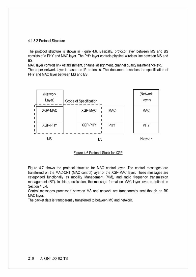
210 A-GN4.00-02-TS
4.1.3.2 Protocol Structure The protocol structure is shown in Figure 4.6. Basically, protocol layer between MS and BS consists of a PHY and MAC layer. The PHY layer controls physical wireless line between MS and BS. MAC layer controls link establishment, channel assignment, channel quality maintenance etc. The upper network layer is based on IP protocols. This document describes the specification of PHY and MAC layer between MS and BS.
Figure 4.6 Protocol Stack for XGP
Figure 4.7 shows the protocol structure for MAC control layer. The control messages are transferred on the MAC-CNT (MAC control) layer of the XGP-MAC layer. These messages are categorized functionally as mobility Management (MM), and radio frequency transmission management (RT). In this specification, the message format on MAC layer level is defined in Section 4.5.4. Control messages processed between MS and network are transparently sent though on BS MAC layer. The packet data is transparently transferred to between MS and network.
XGP-PHY
XGP-MAC
XGP-PHY
XGP-MAC
PHY PHY
MAC
(Network Layer)
(Network Layer)
MAC
MS BS Network
Scope of Specification
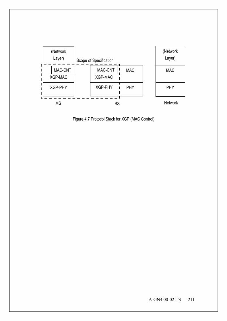
A-GN4.00-02-TS 211
Figure 4.7 Protocol Stack for XGP (MAC Control)
XGP-PHY
XGP-MAC
XGP-PHY
XGP-MAC
PHY PHY
MAC
(Network Layer)
(Network Layer)
MAC
MS BS Network
MAC-CNT
Scope of Specification
MAC-CNT
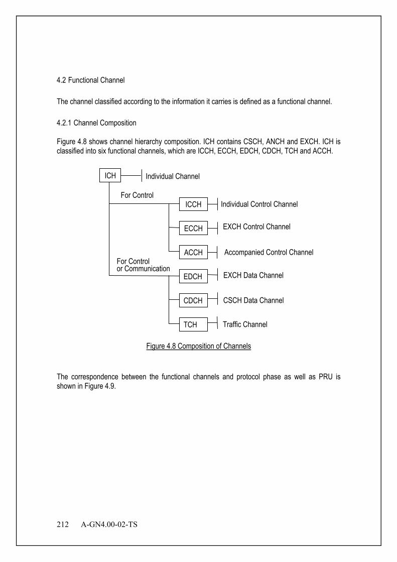
212 A-GN4.00-02-TS
4.2 Functional Channel The channel classified according to the information it carries is defined as a functional channel. 4.2.1 Channel Composition Figure 4.8 shows channel hierarchy composition. ICH contains CSCH, ANCH and EXCH. ICH is classified into six functional channels, which are ICCH, ECCH, EDCH, CDCH, TCH and ACCH.
Figure 4.8 Composition of Channels
The correspondence between the functional channels and protocol phase as well as PRU is shown in Figure 4.9.
Individual Channel
EXCH Control Channel
EXCH Data Channel
Individual Control Channel
Accompanied Control Channel
CSCH Data Channel
Traffic Channel
For Control
For Control or Communication
ECCH
EDCH
ICCH
ACCH
CDCH
TCH
ICH
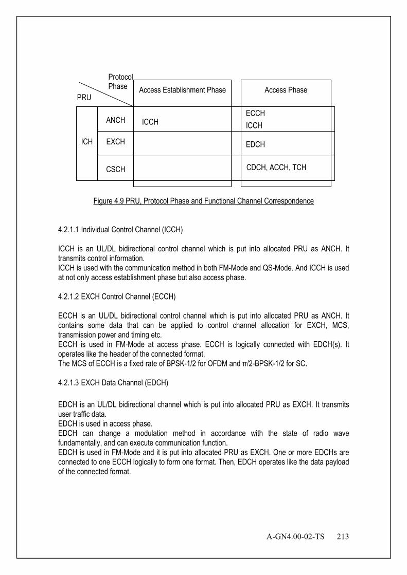
A-GN4.00-02-TS 213
Figure 4.9 PRU, Protocol Phase and Functional Channel Correspondence
4.2.1.1 Individual Control Channel (ICCH) ICCH is an UL/DL bidirectional control channel which is put into allocated PRU as ANCH. It transmits control information. ICCH is used with the communication method in both FM-Mode and QS-Mode. And ICCH is used at not only access establishment phase but also access phase. 4.2.1.2 EXCH Control Channel (ECCH) ECCH is an UL/DL bidirectional control channel which is put into allocated PRU as ANCH. It contains some data that can be applied to control channel allocation for EXCH, MCS, transmission power and timing etc. ECCH is used in FM-Mode at access phase. ECCH is logically connected with EDCH(s). It operates like the header of the connected format. The MCS of ECCH is a fixed rate of BPSK-1/2 for OFDM and π/2-BPSK-1/2 for SC. 4.2.1.3 EXCH Data Channel (EDCH) EDCH is an UL/DL bidirectional channel which is put into allocated PRU as EXCH. It transmits user traffic data. EDCH is used in access phase. EDCH can change a modulation method in accordance with the state of radio wave fundamentally, and can execute communication function. EDCH is used in FM-Mode and it is put into allocated PRU as EXCH. One or more EDCHs are connected to one ECCH logically to form one format. Then, EDCH operates like the data payload of the connected format.
Protocol Phase
ICH
ANCH
EXCH
CSCH
Access Establishment Phase Access Phase
PRU
ICCH
ECCH ICCH
EDCH
CDCH, ACCH, TCH
214 A-GN4.00-02-TS
4.2.1.4 CSCH Data Channel (CDCH) CDCH is an UL/DL bidirectional channel which is put into allocated PRU as CSCH. It transmits user traffic data. CDCH is used in access phase. CDCH can change a modulation method in accordance with the state of radio wave fundamentally, and can execute communication function. It is replaced in order to transmit control information constantly. CDCH is used for the data communications in QS-Mode. It is put into allocated PRU as CSCH. 4.2.1.5 Traffic Channel (TCH) TCH is an UL/DL bidirectional channel which is put into allocated PRU as CSCH. TCH is used in QS-Mode at access phase to transmit bearer constant rate data fundamentally. The MCS of TCH is pre-defined and retransmission control is not performed. TCH is transmitted by the same PRU as ACCH which contains control information. 4.2.1.6 Accompanied Control Channel (ACCH) ACCH is UL/DL bidirectional control channel which accompanies TCH in allocated PRU as CSCH. It transmits control information. ACCH is used by access phase in QS-Mode. Like TCH, the MCS of ACCH is the same as the payload and retransmission control is not performed. 4.3 Optional Functional Control Channel The following functional control channels are optional. Figure 4.10 shows the downlink and uplink control channel composition.
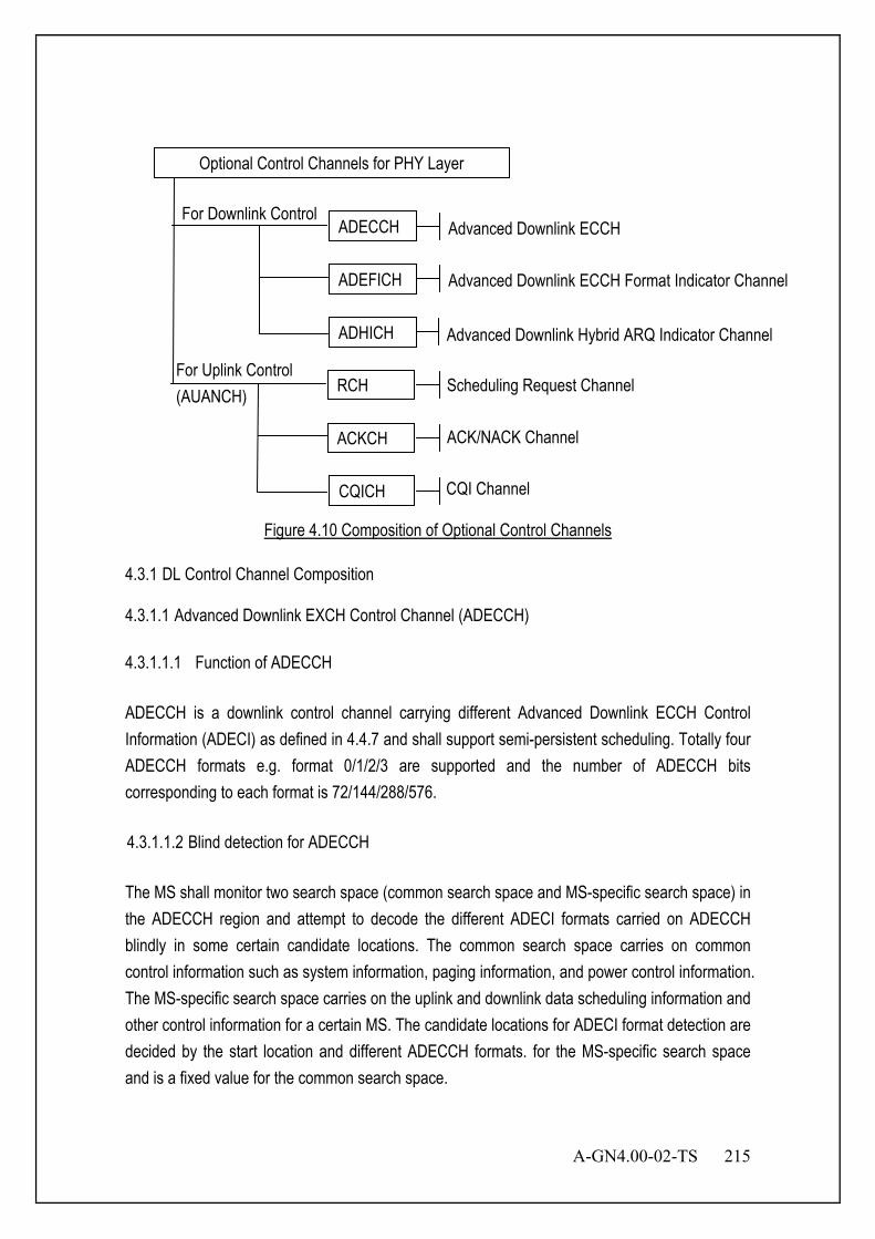
A-GN4.00-02-TS 215
Figure 4.10 Composition of Optional Control Channels
4.3.1 DL Control Channel Composition 4.3.1.1 Advanced Downlink EXCH Control Channel (ADECCH) 4.3.1.1.1 Function of ADECCH ADECCH is a downlink control channel carrying different Advanced Downlink ECCH Control Information (ADECI) as defined in 4.4.7 and shall support semi-persistent scheduling. Totally four ADECCH formats e.g. format 0/1/2/3 are supported and the number of ADECCH bits corresponding to each format is 72/144/288/576. 4.3.1.1.2 Blind detection for ADECCH The MS shall monitor two search space (common search space and MS-specific search space) in the ADECCH region and attempt to decode the different ADECI formats carried on ADECCH blindly in some certain candidate locations. The common search space carries on common control information such as system information, paging information, and power control information. The MS-specific search space carries on the uplink and downlink data scheduling information and other control information for a certain MS. The candidate locations for ADECI format detection are decided by the start location and different ADECCH formats. for the MS-specific search space and is a fixed value for the common search space.
Advanced Downlink ECCH Format Indicator Channel
Advanced Downlink ECCH For Downlink Control
ADEFICH
ADECCH
ADHICH
Optional Control Channels for PHY Layer
ACKCH
RCH
CQICH
For Uplink Control (AUANCH)
CQI Channel
Advanced Downlink Hybrid ARQ Indicator Channel
Scheduling Request Channel
ACK/NACK Channel

216 A-GN4.00-02-TS
The ADECI formats that the MS shall monitor depend on the configured AMT as defined in the ADEDCH part. 4.3.1.2 Advanced Downlink ECCH Format Indicator Channel (ADEFICH) ADEFICH is a downlink control channel carrying the information about the number of OFDM symbols used for transmission of ADECCH in a slot. The set of OFDM symbols possibly used for ADECCH in a slot is given in Table 4.2.
Table 4.2 Number of OFDM Symbols Used for ADECCH
Slot Number of OFDM Symbols for ADECCH
when 10>DLRUN
Slot 1 and 6 1, 2
All Other Cases 1, 2, 3 4.3.1.3 Advanced Downlink Hybrid-ARQ Indicator Channel (ADHICH) ADHICH is a downlink control channel which carries the hybrid-ARQ ACK/NAK for UL data. 4.3.2 Uplink Control Channel Composition 4.3.2.1 AUANCH/RCH RCH carries the Scheduling Request (SR) indication. The SR is received from higher layers. 4.3.2.2 AUANCH/ACKCH ACKCH carries the uplink acknowledgement (ACK) field of corresponding received data in downlink. 4.3.2.3 AUANCH/CQICH
CQICH carries the Channel Quality Indicator (CQI). CQICH also carries the Rank Indication (RI) and Precoding Matrix Indicator (PMI) in case of MIMO.

A-GN4.00-02-TS 217
4.4 PHY Layer Structure and Frame Format 4.4.1 PHY Frame Structure There are three PHY frame types including ANCH, EXCH, and CSCH. ICCH, ECCH, EDCH, CDCH, TCH and ACCH are functional channels put into PHY frame.
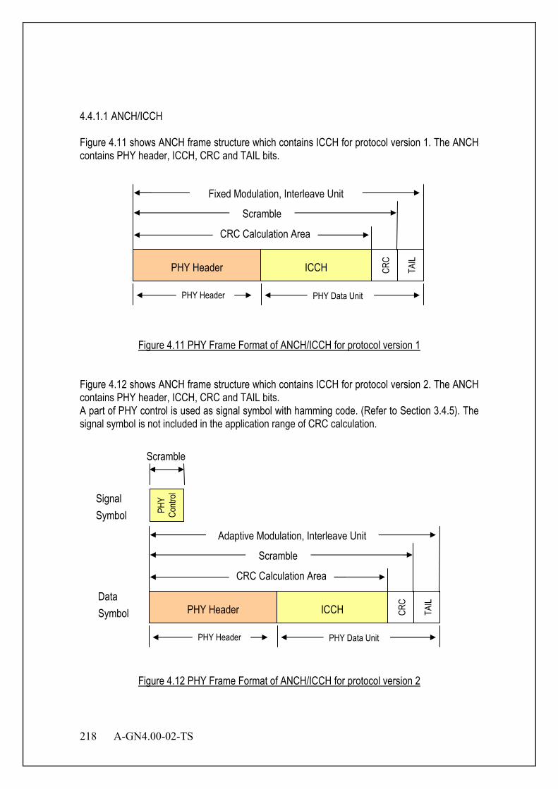
218 A-GN4.00-02-TS
4.4.1.1 ANCH/ICCH Figure 4.11 shows ANCH frame structure which contains ICCH for protocol version 1. The ANCH contains PHY header, ICCH, CRC and TAIL bits.
Figure 4.11 PHY Frame Format of ANCH/ICCH for protocol version 1
Figure 4.12 shows ANCH frame structure which contains ICCH for protocol version 2. The ANCH contains PHY header, ICCH, CRC and TAIL bits. A part of PHY control is used as signal symbol with hamming code. (Refer to Section 3.4.5). The signal symbol is not included in the application range of CRC calculation.
Figure 4.12 PHY Frame Format of ANCH/ICCH for protocol version 2
PHY Header PHY Data Unit
ICCH CRC
TAIL PHY Header
CRC Calculation Area
Scramble
Adaptive Modulation, Interleave Unit
PHY
Contr
ol Signal Symbol
Scramble
Data Symbol
PHY Header PHY Data Unit
ICCH CRC
TAIL PHY Header
CRC Calculation Area
Scramble
Fixed Modulation, Interleave Unit
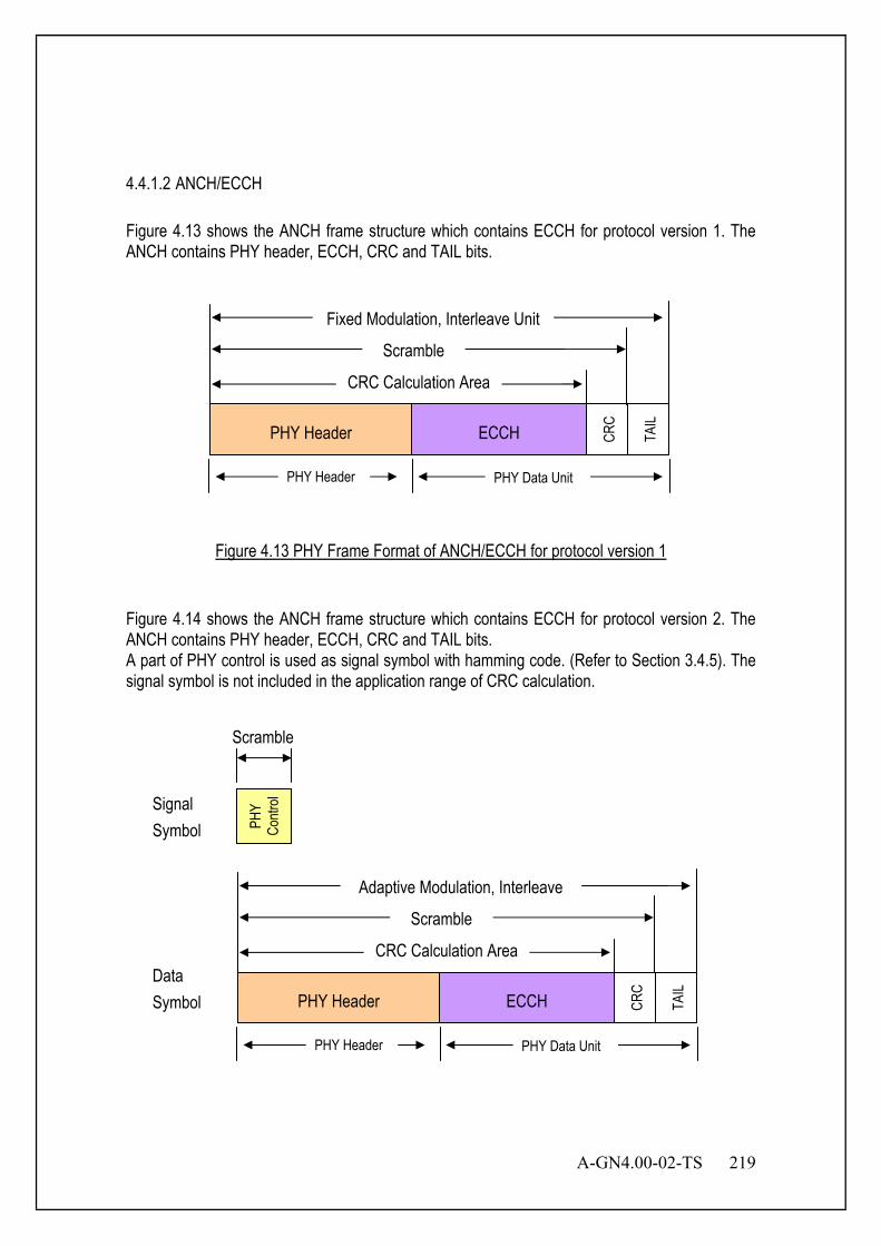
A-GN4.00-02-TS 219
4.4.1.2 ANCH/ECCH Figure 4.13 shows the ANCH frame structure which contains ECCH for protocol version 1. The ANCH contains PHY header, ECCH, CRC and TAIL bits.
Figure 4.13 PHY Frame Format of ANCH/ECCH for protocol version 1
Figure 4.14 shows the ANCH frame structure which contains ECCH for protocol version 2. The ANCH contains PHY header, ECCH, CRC and TAIL bits. A part of PHY control is used as signal symbol with hamming code. (Refer to Section 3.4.5). The signal symbol is not included in the application range of CRC calculation.
PHY Header PHY Data Unit
ECCH CRC
TAIL PHY Header
CRC Calculation Area
Scramble
Adaptive Modulation, Interleave
Signal Symbol PH
Y Co
ntrol
Scramble
Data Symbol
PHY Header PHY Data Unit
ECCH CRC
TAIL PHY Header
CRC Calculation Area
Scramble
Fixed Modulation, Interleave Unit

220 A-GN4.00-02-TS
Figure 4.14 PHY Frame Format of ANCH/ECCH for protocol version 2
4.4.1.3 EXCH/EDCH Figure 4.15 shows EXCH/EDCH frame structure which consists of one or more EXCH(s) except for EMB-MIMO. The EXCH contains EDCH, CRC and TAIL bits.
Figure 4.15 PHY Frame Format of EXCH/EDCH except for EMB-MIMO
Figure 4.16 shows EXCH/EDCH frame structure which consists of one or more EXCH(s) for EMB-MIMO. The EXCH contains EDCH, CRC and TAIL bits. A part of PHY control is used as signal symbol with hamming code. (Refer to Section 3.4.5). The signal symbol is not included in the application range of CRC calculation.
EDCH CRC
TAIL
PHY Data Unit One PRU
CRC Calculation Area Scramble
Adaptive Modulation, Interleave
Signal Symbol PH
Y Co
ntrol
Scramble
Data Symbol
EDCH CRC
TAIL
PHY Data Unit
One or Two PRUs
CRC Calculation Area
Scramble
Adaptive Modulation, Interleave
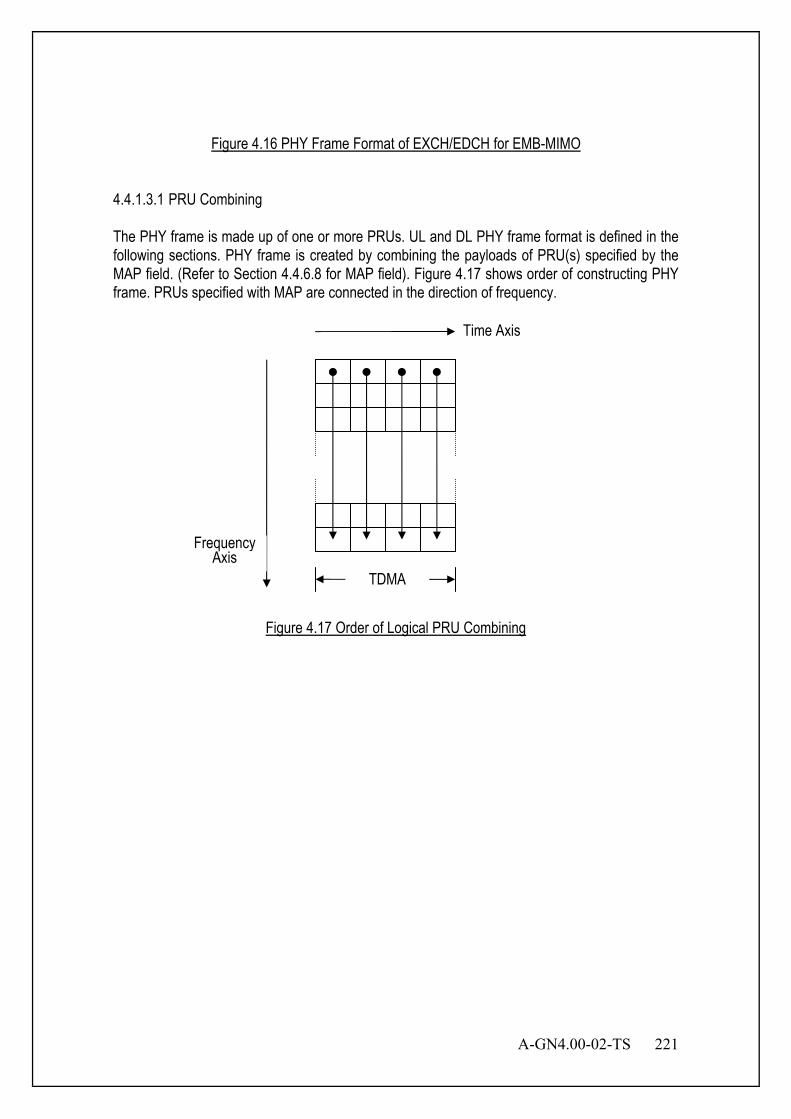
A-GN4.00-02-TS 221
Figure 4.16 PHY Frame Format of EXCH/EDCH for EMB-MIMO
4.4.1.3.1 PRU Combining The PHY frame is made up of one or more PRUs. UL and DL PHY frame format is defined in the following sections. PHY frame is created by combining the payloads of PRU(s) specified by the MAP field. (Refer to Section 4.4.6.8 for MAP field). Figure 4.17 shows order of constructing PHY frame. PRUs specified with MAP are connected in the direction of frequency.
Figure 4.17 Order of Logical PRU Combining
TDMA
Frequency Axis
Time Axis
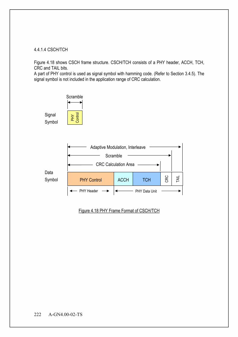
222 A-GN4.00-02-TS
4.4.1.4 CSCH/TCH Figure 4.18 shows CSCH frame structure. CSCH/TCH consists of a PHY header, ACCH, TCH, CRC and TAIL bits. A part of PHY control is used as signal symbol with hamming code. (Refer to Section 3.4.5). The signal symbol is not included in the application range of CRC calculation.
Figure 4.18 PHY Frame Format of CSCH/TCH
TCH CRC
TAIL
PHY Header PHY Data Unit
PHY Control ACCH
CRC Calculation Area
Scramble
Adaptive Modulation, Interleave
Data Symbol
PHY
Contr
ol Signal Symbol
Scramble
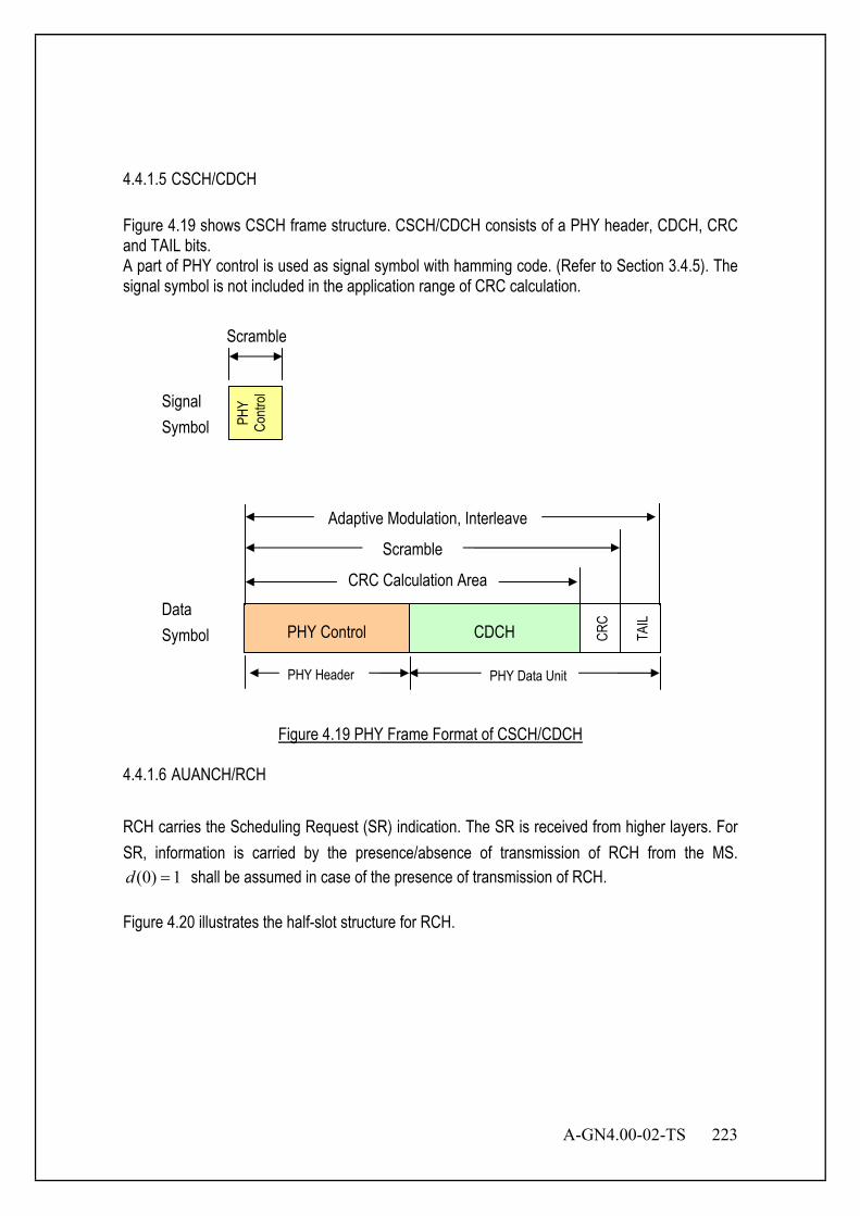
A-GN4.00-02-TS 223
4.4.1.5 CSCH/CDCH Figure 4.19 shows CSCH frame structure. CSCH/CDCH consists of a PHY header, CDCH, CRC and TAIL bits. A part of PHY control is used as signal symbol with hamming code. (Refer to Section 3.4.5). The signal symbol is not included in the application range of CRC calculation.
Figure 4.19 PHY Frame Format of CSCH/CDCH
4.4.1.6 AUANCH/RCH
RCH carries the Scheduling Request (SR) indication. The SR is received from higher layers. For SR, information is carried by the presence/absence of transmission of RCH from the MS.
1)0( =d shall be assumed in case of the presence of transmission of RCH.
Figure 4.20 illustrates the half-slot structure for RCH.
CDCH CRC
TAIL
PHY Header PHY Data Unit
PHY Control
CRC Calculation Area
Scramble
Adaptive Modulation, Interleave
PHY
Contr
ol
Data Symbol
Signal Symbol
Scramble
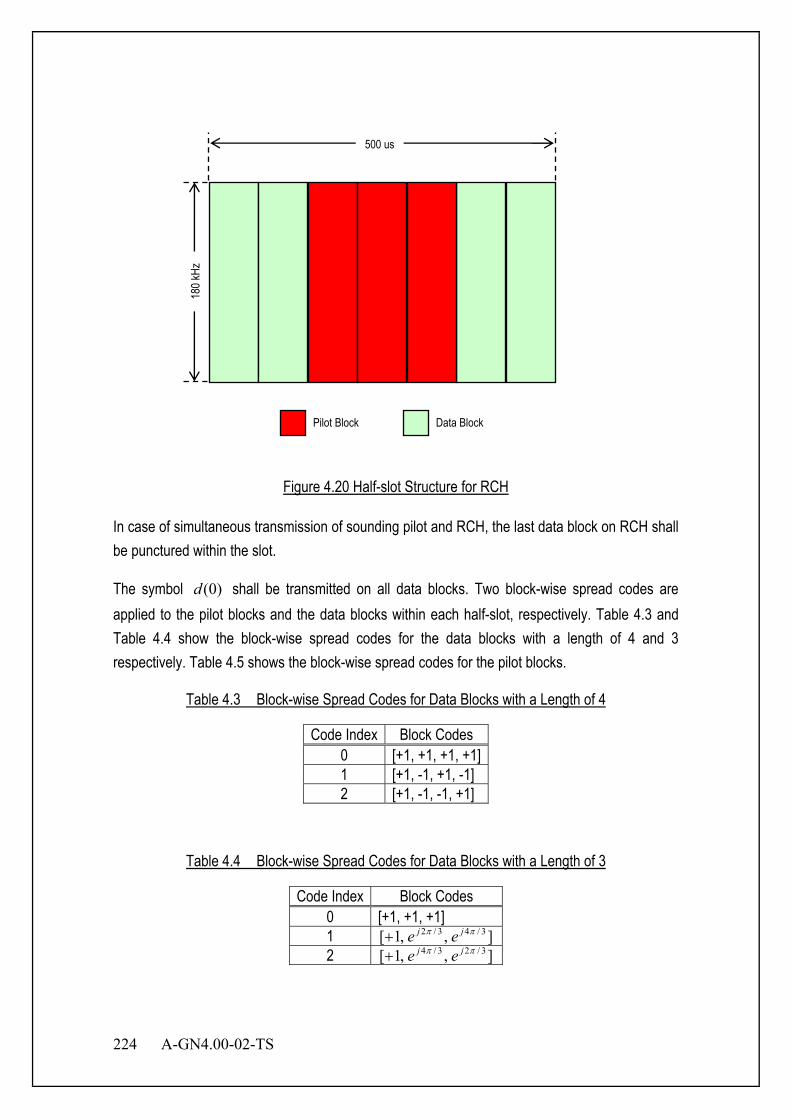
224 A-GN4.00-02-TS
Figure 4.20 Half-slot Structure for RCH
In case of simultaneous transmission of sounding pilot and RCH, the last data block on RCH shall be punctured within the slot.
The symbol )0(d shall be transmitted on all data blocks. Two block-wise spread codes are applied to the pilot blocks and the data blocks within each half-slot, respectively. Table 4.3 and Table 4.4 show the block-wise spread codes for the data blocks with a length of 4 and 3 respectively. Table 4.5 shows the block-wise spread codes for the pilot blocks.
Table 4.3 Block-wise Spread Codes for Data Blocks with a Length of 4
Code Index Block Codes 0 [+1, +1, +1, +1] 1 [+1, -1, +1, -1] 2 [+1, -1, -1, +1]
Table 4.4 Block-wise Spread Codes for Data Blocks with a Length of 3
Code Index Block Codes 0 [+1, +1, +1] 1 ],,1[ 3/43/2 ππ jj ee+ 2 ],,1[ 3/23/4 ππ jj ee+
180 k
Hz
500 us
Pilot Block Data Block

A-GN4.00-02-TS 225
Table 4.5 Block-wise spread codes for pilot blocks
Code index Block codes 0 [+1, +1, +1] 1 ],,1[ 3/43/2 ππ jj ee+ 2 ],,1[ 3/23/4 ππ jj ee+
The SR shall be transmitted on the RCH resource which is MS specific and configured by higher layers. The higher layer configured parameters include SR transmission periodicity SRPeriodicity and slot offset NOFFSET,SR. SR transmission instances are the slots satisfying
( ) 0mod2/10 , =−+× yPeriodicitSROFFSETsf SRNnn , where fn is the system frame number,
and sn = {0,1,…, 19} is the half-slot index within the frame.
4.4.1.7 AUANCH/ACKCH
ACKCH carries the uplink acknowledgement (ACK) field of corresponding received data in downlink. This field is used for the acknowledgement of PHY layer retransmission control, such as HARQ. The ACK/NACK bits are received per codeword from higher layers.
Figure 4.21 illustrates the half-slot structure for ACKCH.
180 k
Hz
500 us
Pilot Block Data Block

226 A-GN4.00-02-TS
Figure 4.21 Half-slot Structure for ACKCH
In case of simultaneous transmission of sounding pilot and ACKCH, the last SC-FDMA symbol on ACKCH shall be punctured.
For ACKCH, one or two explicit bits are transmitted, respectively. The block of bits )1(),...,0( bit −Mbb shall be modulated as described in Table 4.6, resulting in a complex-valued
symbol )0(d . The symbol )0(d shall be transmitted on all data blocks. Two block-wise spread codes are applied to the pilot blocks and the data blocks respectively. Table 4.3 and Table 4.4 show the block-wise spread codes for the data blocks with a length of 4 and 3 respectively. Table 4.5 shows the block-wise spread codes for the pilot blocks.
Table 4.6 Modulation Symbol )0(d for ACKCH
)1(),...,0( bit −Mbb )0(d 0 1 1 1− 00 1 01 j− 10 j 11 1−
4.4.1.8 AUANCH/CQICH
CQICH carries the Channel Quality Indicator (CQI). CQICH also carries the Rank Indication (RI) and Precoding Matrix Indicator (PMI) in case of MIMO.
Figure 4.22 illustrates the half-slot structure for CQICH

A-GN4.00-02-TS 227
Figure 4.22 Half-slot Structure for CQICH
The channel quality bits input to the channel coding block are denoted by 13210 ,...,,,, −Aaaaaa where A is the number of bits. The number of channel quality bits depends on the transmission format. The channel quality indication is coded with the (20, A) code. The block of coded bits )19(),...,0( bb shall firstly be QPSK modulated as described in Appendix B.10.2, resulting in a block of complex-valued modulation symbols )9(),...,0( dd . The i-th modulated symbol is transmitted on the i-th data block within the slot. 4.4.2 Signal Symbol 4.4.2.1 Signal Symbol Structure Figure 4.23 shows signal symbol structure for CSCH. It consists of MI only. Refer to Section 4.4.6 for MI field.
Figure 4.23 Signal Symbol Structure for CSCH
180 k
Hz
500 us
Pilot Block Data Block
MI(4)
Signal Symbol
MSB LSB
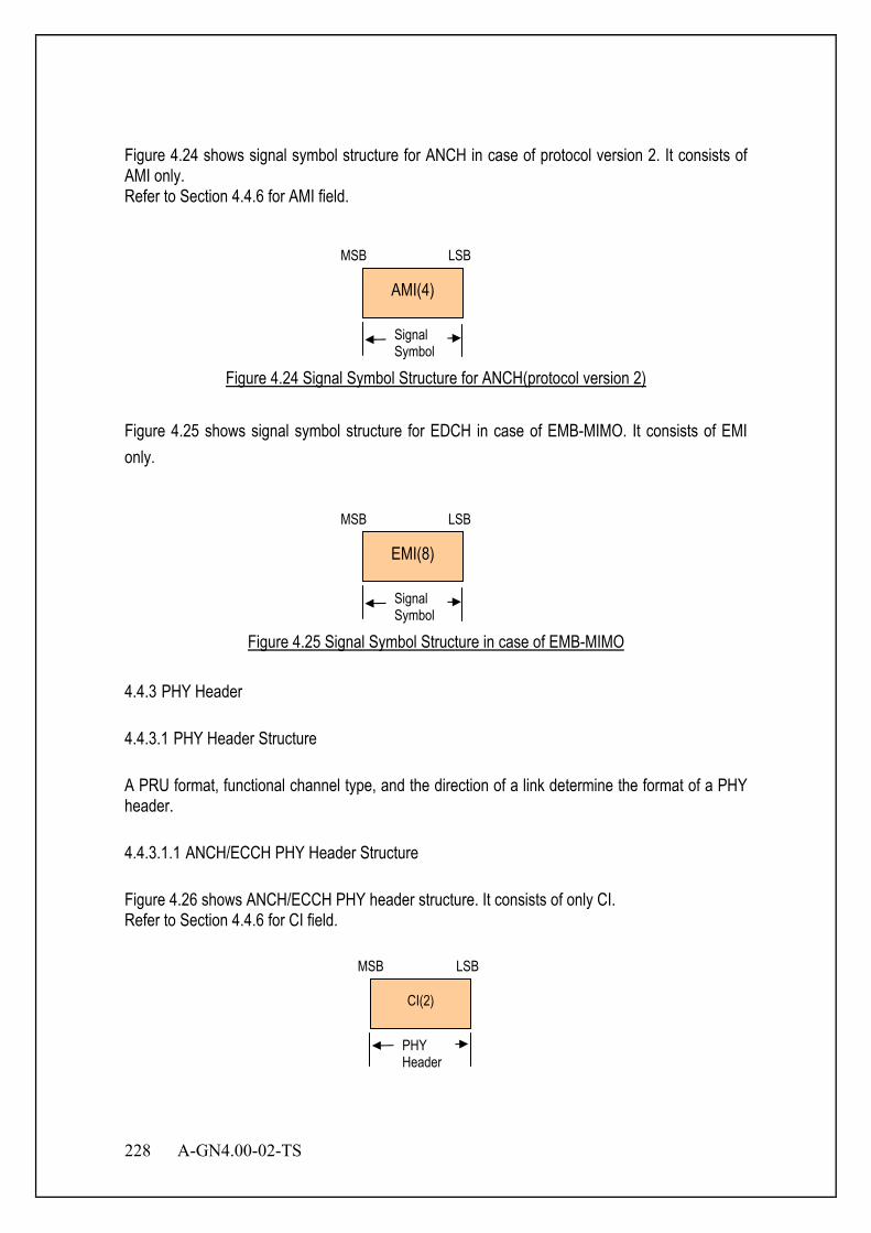
228 A-GN4.00-02-TS
Figure 4.24 shows signal symbol structure for ANCH in case of protocol version 2. It consists of AMI only. Refer to Section 4.4.6 for AMI field.
Figure 4.24 Signal Symbol Structure for ANCH(protocol version 2)
Figure 4.25 shows signal symbol structure for EDCH in case of EMB-MIMO. It consists of EMI only.
Figure 4.25 Signal Symbol Structure in case of EMB-MIMO
4.4.3 PHY Header 4.4.3.1 PHY Header Structure A PRU format, functional channel type, and the direction of a link determine the format of a PHY header. 4.4.3.1.1 ANCH/ECCH PHY Header Structure Figure 4.26 shows ANCH/ECCH PHY header structure. It consists of only CI. Refer to Section 4.4.6 for CI field.
AMI(4)
Signal Symbol
MSB LSB
CI(2)
PHY Header
MSB LSB
EMI(8)
Signal Symbol
MSB LSB
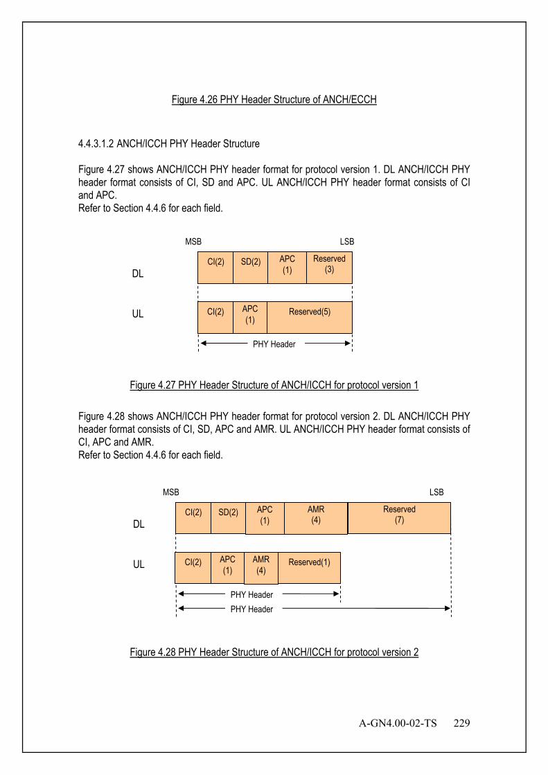
A-GN4.00-02-TS 229
Figure 4.26 PHY Header Structure of ANCH/ECCH
4.4.3.1.2 ANCH/ICCH PHY Header Structure Figure 4.27 shows ANCH/ICCH PHY header format for protocol version 1. DL ANCH/ICCH PHY header format consists of CI, SD and APC. UL ANCH/ICCH PHY header format consists of CI and APC. Refer to Section 4.4.6 for each field.
Figure 4.27 PHY Header Structure of ANCH/ICCH for protocol version 1
Figure 4.28 shows ANCH/ICCH PHY header format for protocol version 2. DL ANCH/ICCH PHY header format consists of CI, SD, APC and AMR. UL ANCH/ICCH PHY header format consists of CI, APC and AMR. Refer to Section 4.4.6 for each field.
Figure 4.28 PHY Header Structure of ANCH/ICCH for protocol version 2
UL
DL
CI(2) APC (1)
Reserved(1)
PHY Header
CI(2) SD(2) Reserved (7)
APC (1)
MSB LSB
AMR (4)
AMR (4)
PHY Header
CI(2) APC (1)
Reserved(5) UL
PHY Header
CI(2) SD(2) Reserved (3)
APC (1) DL
MSB LSB

230 A-GN4.00-02-TS
4.4.3.1.3 CSCH/CDCH PHY Header Structure Figure 4.29 shows the structure of UL/DL CSCH/CDCH PHY header. DL CSCH/CDCH PHY header contains CI, MR, SD, PC and ACK. UL CSCH/CDCH PHY header contains CI, MR, PC and ACK. Refer to Section 4.4.6 for each field.
Figure 4.29 PHY Header Structure of CSCH/CDCH
4.4.3.1.4 CSCH/TCH PHY Header Structure Figure 4.30 shows the structure of UL/DL PHY header of CSCH/TCH. CI, MR, SD, and PC are contained in DL PHY header. CI, MR and PC are contained in UL PHY header. Refer to Section 4.4.6 for each field.
PHY Header
CI(2) MR(4) SD(2) PC(1) Reserved (7) DL
UL Reserved
(9)
MSB LSB
CI(2) MR(4) PC(1)
Figure 4.30 PHY Header Structure of CSCH/TCH
UL Reserved
(8)
PHY Header
CI(2) MR(4) SD(2) PC(1) ACK(1) DL
Reserved (6)
MSB
CI(2) MR(4) PC(1) ACK(1)
LSB
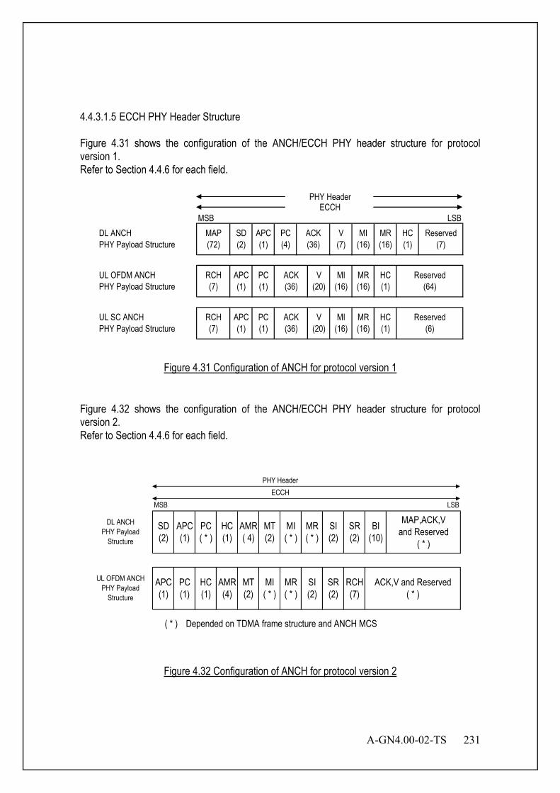
A-GN4.00-02-TS 231
4.4.3.1.5 ECCH PHY Header Structure Figure 4.31 shows the configuration of the ANCH/ECCH PHY header structure for protocol version 1. Refer to Section 4.4.6 for each field.
MSB LSB
PHY HeaderECCH
DL ANCHPHY Payload Structure
MAP(72)
SD(2)
APC(1)
PC(4)
ACK(36)
V(7)
MI(16)
HC(1)
Reserved(7)
UL OFDM ANCHPHY Payload Structure
RCH(7)
APC(1)
PC(1)
ACK(36)
V(20)
MI(16)
ACK(36)
V(20)
MI(16)
MR(16)
MR(16)
HC(1)
UL SC ANCHPHY Payload Structure
RCH(7)
APC(1)
PC(1)
Reserved(6)
MR(16)
HC(1)
Reserved(64)
Figure 4.31 Configuration of ANCH for protocol version 1 Figure 4.32 shows the configuration of the ANCH/ECCH PHY header structure for protocol version 2. Refer to Section 4.4.6 for each field.
MSB LSB
( * ) Depended on TDMA frame structure and ANCH MCS
PHY HeaderECCH
MI( * )
MR( * )
DL ANCHPHY Payload
Structure
MI( * )
MR( * )
SD(2)
UL OFDM ANCHPHY Payload
Structure
RCH(7)
APC(1)
PC( * )
HC(1)
AMR( 4)
SI(2)
MT(2)
SR(2)
ACK,V and Reserved( * )
BI(10)
MAP,ACK,Vand Reserved
( * )
APC(1)
PC(1)
HC(1)
AMR(4)
MT(2)
SI(2)
SR(2)
Figure 4.32 Configuration of ANCH for protocol version 2
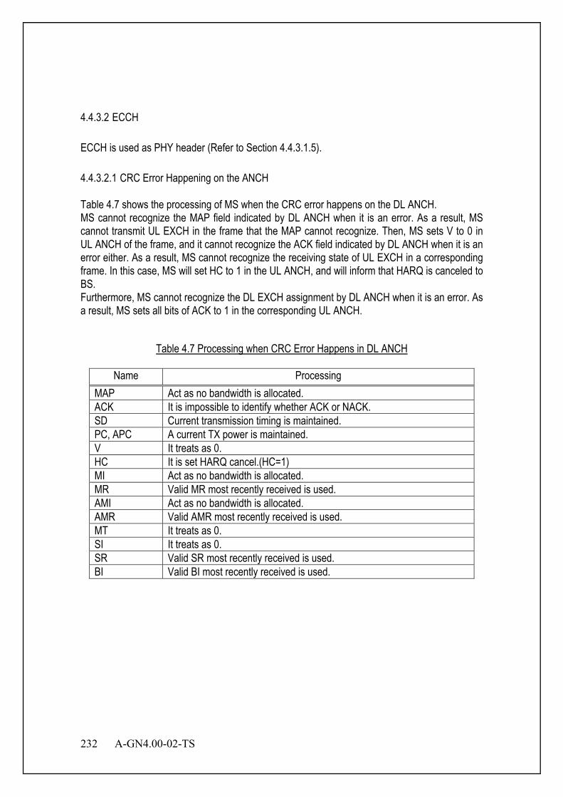
232 A-GN4.00-02-TS
4.4.3.2 ECCH ECCH is used as PHY header (Refer to Section 4.4.3.1.5). 4.4.3.2.1 CRC Error Happening on the ANCH Table 4.7 shows the processing of MS when the CRC error happens on the DL ANCH. MS cannot recognize the MAP field indicated by DL ANCH when it is an error. As a result, MS cannot transmit UL EXCH in the frame that the MAP cannot recognize. Then, MS sets V to 0 in UL ANCH of the frame, and it cannot recognize the ACK field indicated by DL ANCH when it is an error either. As a result, MS cannot recognize the receiving state of UL EXCH in a corresponding frame. In this case, MS will set HC to 1 in the UL ANCH, and will inform that HARQ is canceled to BS. Furthermore, MS cannot recognize the DL EXCH assignment by DL ANCH when it is an error. As a result, MS sets all bits of ACK to 1 in the corresponding UL ANCH.
Table 4.7 Processing when CRC Error Happens in DL ANCH
Name Processing MAP Act as no bandwidth is allocated. ACK It is impossible to identify whether ACK or NACK. SD Current transmission timing is maintained. PC, APC A current TX power is maintained. V It treats as 0. HC It is set HARQ cancel.(HC=1) MI Act as no bandwidth is allocated. MR Valid MR most recently received is used. AMI Act as no bandwidth is allocated. AMR Valid AMR most recently received is used. MT It treats as 0. SI It treats as 0. SR Valid SR most recently received is used. BI Valid BI most recently received is used.

A-GN4.00-02-TS 233
Table 4.8 shows the processing when the CRC error happens on the UL ANCH. BS cannot recognize the ACK field indicated by UL ANCH when it is an error. Therefore, BS cannot recognize the receiving state of DL EXCH in a corresponding frame. In this case, BS will set HC to 1 in the DL ANCH of the timing which retransmits data, and will inform that HARQ is canceled to MS. Additionally, BS cannot recognize the MI and V field indicated by UL ANCH when it is an error. AS a result, BS cannot receive UL EXCH in the frame. Then, BS sets all bits of ACK to 1 in the corresponding DL ANCH.
Table 4.8 Processing when Error Happens in UL ANCH
Name Processing RCH Act as if no bandwidth assignment request has been sent. ACK If CRC error happens, it is impossible to identify whether it is. PC , APC A current TX power is maintained. V It treats as 0. HC It is set HARQ cancel.(HC=1) MI Act as no bandwidth is allocated. MR Valid MR most recently received is used. AMI Act as no bandwidth is allocated. AMR Valid AMR most recently received is used. MT It treats as 0. SI It treats as 0. SR Valid SR most recently received is used.

234 A-GN4.00-02-TS
4.4.4 PHY Payload 4.4.4.1 PHY Payload Structure Figure 4.33 shows the configuration of PHY payload.
Figure 4.33 Configuration of PHY Payload
4.4.5 PHY Trailer 4.4.5.1 CRC The PHY payload length and CRC length are changed flexibly according to the MCS. In this section, PHY payload length, and CRC length is defined according to the MCS and the PHY data unit. CRC (Cyclic Redundancy Code) 16 is inserted. Section 4.4.1 shows the range of the CRC calculation. 4.4.5.2 TAIL TAIL field is inserted so that the state of the shift register of the convolutional encoding module becomes empty. Assuming K is the constraint length of error correction, then TAIL bit length is K-1 bits. Number of TAIL bits is 6. 4.4.6 PHY Control Layer This section explains each field in the PHY frame. 4.4.6.1 Channel Identifier (CI) CI shows what kind of information has been transmitted by PRU.
MAC Frame
PHY Payload
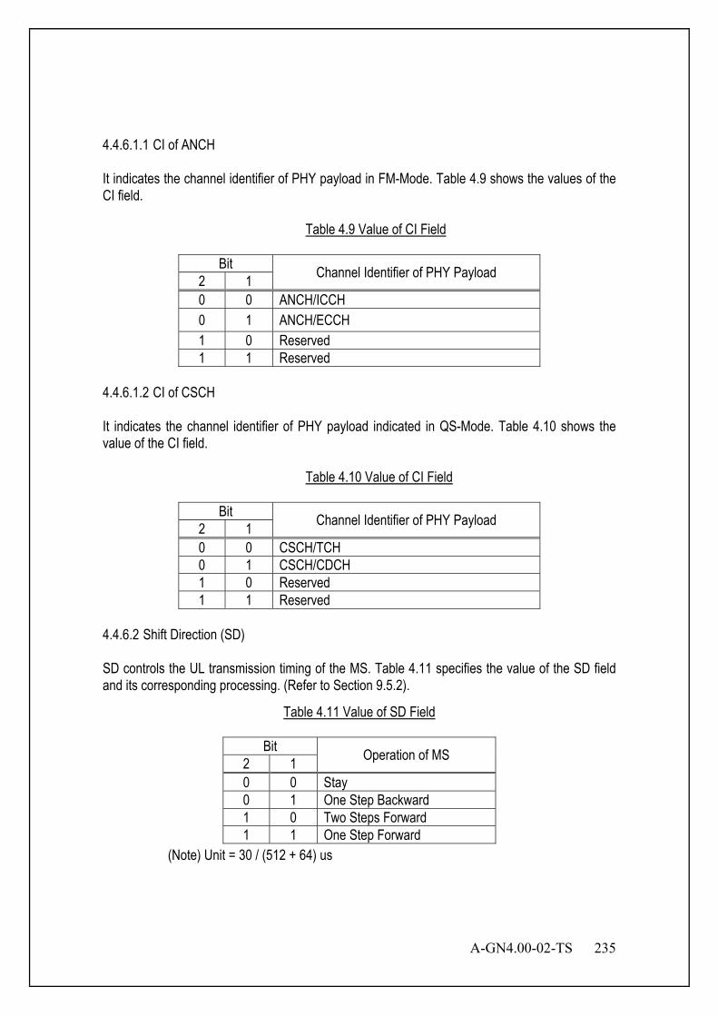
A-GN4.00-02-TS 235
4.4.6.1.1 CI of ANCH It indicates the channel identifier of PHY payload in FM-Mode. Table 4.9 shows the values of the CI field.
Table 4.9 Value of CI Field
Bit Channel Identifier of PHY Payload 2 1 0 0 ANCH/ICCH 0 1 ANCH/ECCH 1 0 Reserved 1 1 Reserved
4.4.6.1.2 CI of CSCH It indicates the channel identifier of PHY payload indicated in QS-Mode. Table 4.10 shows the value of the CI field.
Table 4.10 Value of CI Field
Bit Channel Identifier of PHY Payload 2 1 0 0 CSCH/TCH 0 1 CSCH/CDCH 1 0 Reserved 1 1 Reserved
4.4.6.2 Shift Direction (SD) SD controls the UL transmission timing of the MS. Table 4.11 specifies the value of the SD field and its corresponding processing. (Refer to Section 9.5.2).
Table 4.11 Value of SD Field
Bit Operation of MS 2 1 0 0 Stay 0 1 One Step Backward 1 0 Two Steps Forward 1 1 One Step Forward
(Note) Unit = 30 / (512 + 64) us

236 A-GN4.00-02-TS
4.4.6.3 ANCH Power Control (APC) APC controls the transmission power of the ANCH of the MS so that signals from different MSs will be received by BS at the same level. Because once UL radio wave which has different reception level is detected, BS will control the UL transmission power either by increasing or decreasing APC field according to the UL reception level for each MS. (Refer to Section 9.5.1).
Table 4.12 Value of APC Field
APC Value
Operation of MS
0 Decrease transmission power. 1 Increase transmission power.
(Note) Unit = 1 dB 4.4.6.4 Power Control (PC) PC controls the transmission power of the EXCH or CSCH of the MS so that signals from different MSs will be received by BS at the same level. Because once UL radio wave which has different reception level is detected, BS will control the UL transmission power either by increasing or decreasing PC field according to the UL reception level for each MS. (Refer to Section 9.5.1).
Table 4.13 Value of PC Field
PC Value Operation of MS 0 Decrease transmission power. 1 Increase transmission power.
(Note) Unit = 1 dB

A-GN4.00-02-TS 237
UL ECCH contains power control fields for 1 frame by 1 bit, and DL ECCH contains power control fields for each slot, and controls each slot separately. Table 4.14 shows the PC field of each slot. This field length of DL ECCH is depended on TDMA frame structure as the number of UL slots “NUSL”.
Table 4.14 PC Field Composition
First Bit Second Bit … Last Bit Controlled Slot Slot 1 Slot 2 … Slot NUSL
Uplink power control controls the transmit power of the different optional uplink physical channels. The current maximum power can not exceed the configured MS transmitted power. The MS Transmit power for the AUEDCH transmission is mainly determined by the bandwidth of the AUEDCH resource assignment, pathloss and the value configured in TPC command. TPC command is included in ADECCH with ADECI format 0 or jointly coded with other TPC commands in ADECCH with ADECI format 3/3A whose CRC parity bits are scrambled with TPC-AUEDCH-MSID. The MS Transmit power for the Sounding Pilot transmission is based on the MS Transmit power for the AUEDCH transmission and some adjustment is introduced. The MS Transmit power for the AUANCH transmission is mainly determined by a AUANCH format dependent value and TPC command. TPC command is included in a ADECCH with ADECI format 1A/1B/1D/1/2A/2 or sent jointly coded with other MS specific AUANCH correction values on a ADECCH with ADECI format 3/3A whose CRC parity bits are scrambled with TPC-AUANCH-MSID. 4.4.6.5 MCS Indicator (MI) and MCS Request (MR) The MI field indicates the MCS of the adaptive modulation part in the DL PHY frame. The MR field indicates the UL MCS requested by the MS according to the result of the UL signal monitoring. Table 4.15 and Table 4.16 show the correspondence between each field and the MCS.
Table 4.15 MCSs for OFDM
Bit Modulation Class Puncturing Rate Efficiency
4 3 2 1 0 0 0 0
BPSK 1 0.5
0 0 0 1 3/4 0.67 0 0 1 0
QPSK 1 1
0 0 1 1 4/6 1.5 0 1 0 0 Reserved - - 0 1 0 1 16QAM 1 2
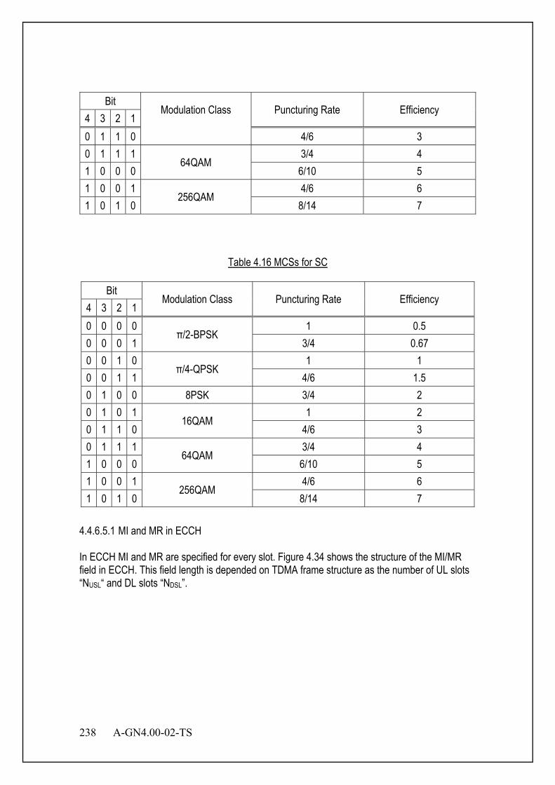
238 A-GN4.00-02-TS
Bit Modulation Class Puncturing Rate Efficiency
4 3 2 1 0 1 1 0 4/6 3 0 1 1 1
64QAM 3/4 4
1 0 0 0 6/10 5 1 0 0 1
256QAM 4/6 6
1 0 1 0 8/14 7
Table 4.16 MCSs for SC
Bit Modulation Class Puncturing Rate Efficiency
4 3 2 1 0 0 0 0
π/2-BPSK 1 0.5
0 0 0 1 3/4 0.67 0 0 1 0
π/4-QPSK 1 1
0 0 1 1 4/6 1.5 0 1 0 0 8PSK 3/4 2 0 1 0 1
16QAM 1 2
0 1 1 0 4/6 3 0 1 1 1
64QAM 3/4 4
1 0 0 0 6/10 5 1 0 0 1
256QAM 4/6 6
1 0 1 0 8/14 7 4.4.6.5.1 MI and MR in ECCH In ECCH MI and MR are specified for every slot. Figure 4.34 shows the structure of the MI/MR field in ECCH. This field length is depended on TDMA frame structure as the number of UL slots “NUSL“ and DL slots “NDSL”.

A-GN4.00-02-TS 239
Figure 4.34 MI and MR Indication in ECCH
Slot 1 MI
MI MR
Slot 2 MI … Slot N MI Slot 1 MR Slot 2 MR … Slot N MR 4 4 4 4 4 4
MSB LSB
4 x the number of slots N 4 x the number of slots N
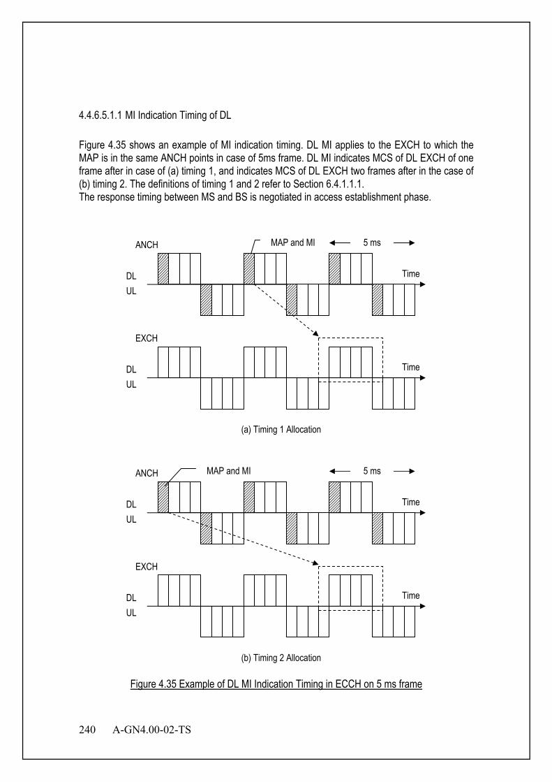
240 A-GN4.00-02-TS
4.4.6.5.1.1 MI Indication Timing of DL Figure 4.35 shows an example of MI indication timing. DL MI applies to the EXCH to which the MAP is in the same ANCH points in case of 5ms frame. DL MI indicates MCS of DL EXCH of one frame after in case of (a) timing 1, and indicates MCS of DL EXCH two frames after in the case of (b) timing 2. The definitions of timing 1 and 2 refer to Section 6.4.1.1.1. The response timing between MS and BS is negotiated in access establishment phase.
TimeDLUL
EXCH
(a) Timing 1 Allocation
MAP and MI 5 ms
Time
ANCH
Time
EXCH
(b) Timing 2 Allocation
MAP and MI 5 ms
Time
ANCH
DLUL
DLUL
DLUL
Figure 4.35 Example of DL MI Indication Timing in ECCH on 5 ms frame
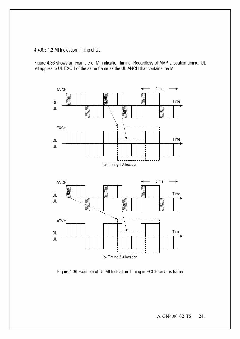
A-GN4.00-02-TS 241
4.4.6.5.1.2 MI Indication Timing of UL Figure 4.36 shows an example of MI indication timing. Regardless of MAP allocation timing, UL MI applies to UL EXCH of the same frame as the UL ANCH that contains the MI.
TimeDLUL
EXCH
(a) Timing 1 Allocation
5 ms
MAP
Time
ANCH
Time
EXCH
(b) Timing 2 Allocation
5 ms
Time
ANCH
DLUL
DLUL
DLUL
MI
MAP
MI
Figure 4.36 Example of UL MI Indication Timing in ECCH on 5ms frame

242 A-GN4.00-02-TS
4.4.6.5.2 MI and MR in CSCH In CSCH, MI and MR show the MCS of the PRU itself under communication. 4.4.6.5.2.1 MI Indication Timing of DL Figure 4.37 shows the frame position where MI field of DL PHY header is applied. MI applies to the DL PHY payload following DL PHY header in the same frame.
TimeDLUL
5 msMI
Figure 4.37 DL MI Indication Timing in CSCH
4.4.6.5.2.2 MI Indication Timing of UL Figure 4.38 shows the frame position where MI field of UL PHY header is applied. MI applies to the UL PHY payload following UL PHY header in the same frame.
TimeDLUL
5 ms
MI
Figure 4.38 UL MI Indication Timing in CSCH
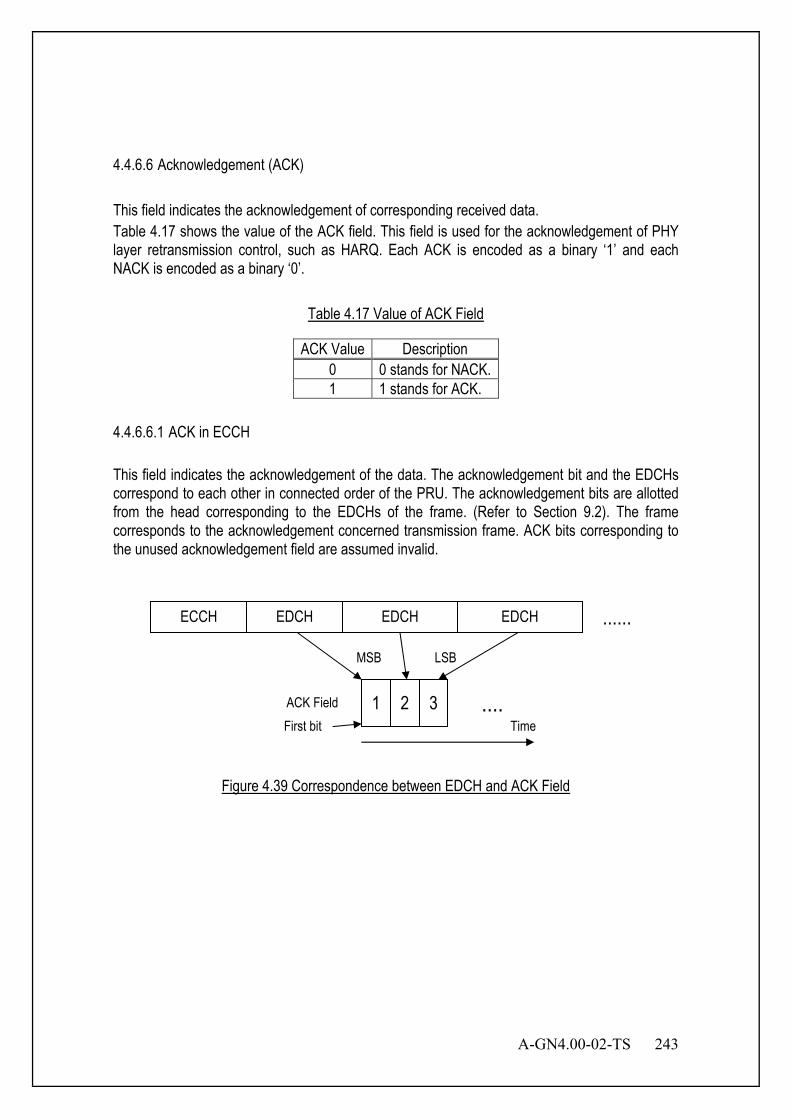
A-GN4.00-02-TS 243
4.4.6.6 Acknowledgement (ACK) This field indicates the acknowledgement of corresponding received data. Table 4.17 shows the value of the ACK field. This field is used for the acknowledgement of PHY layer retransmission control, such as HARQ. Each ACK is encoded as a binary ‘1’ and each NACK is encoded as a binary ‘0’.
Table 4.17 Value of ACK Field
ACK Value Description 0 0 stands for NACK. 1 1 stands for ACK.
4.4.6.6.1 ACK in ECCH This field indicates the acknowledgement of the data. The acknowledgement bit and the EDCHs correspond to each other in connected order of the PRU. The acknowledgement bits are allotted from the head corresponding to the EDCHs of the frame. (Refer to Section 9.2). The frame corresponds to the acknowledgement concerned transmission frame. ACK bits corresponding to the unused acknowledgement field are assumed invalid.
....
......
1ACK Field
MSB
ECCH EDCH EDCH EDCH
2 3First bit
LSB
Time
Figure 4.39 Correspondence between EDCH and ACK Field
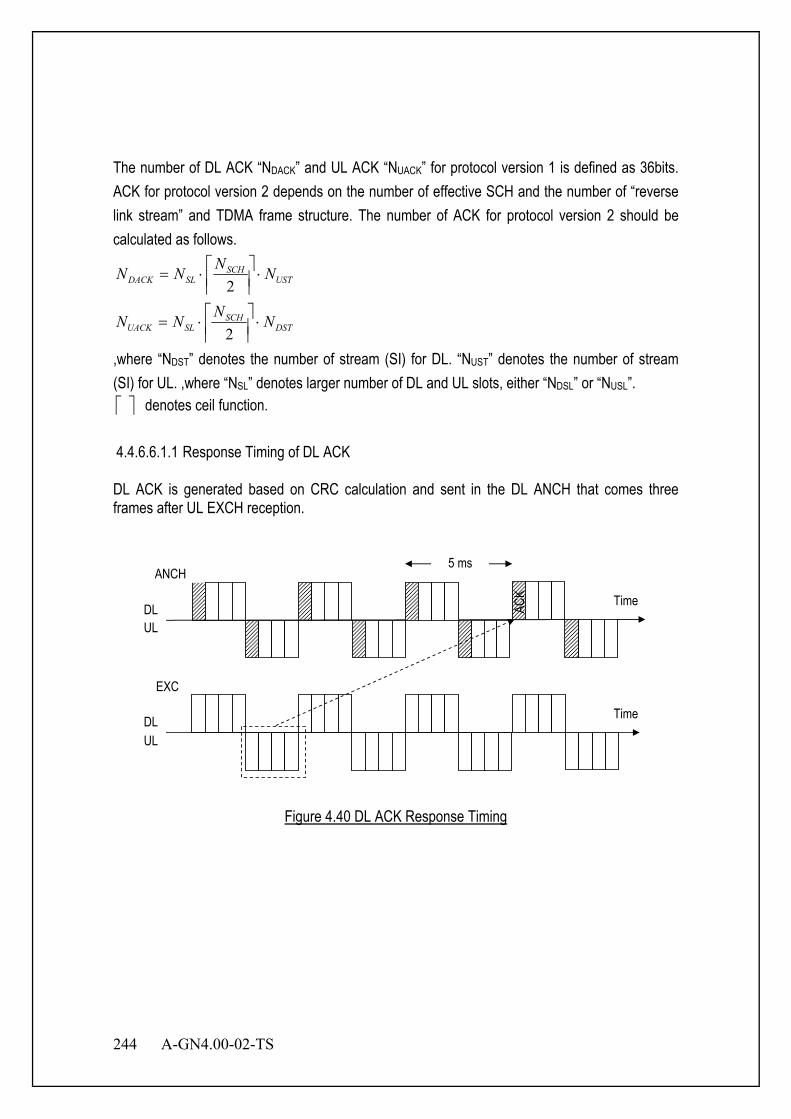
244 A-GN4.00-02-TS
The number of DL ACK “NDACK” and UL ACK “NUACK” for protocol version 1 is defined as 36bits. ACK for protocol version 2 depends on the number of effective SCH and the number of “reverse link stream” and TDMA frame structure. The number of ACK for protocol version 2 should be calculated as follows.
USTSCH
SLDACK NNNN ⋅
⋅=
2
DSTSCH
SLUACK NNNN ⋅
⋅=
2
,where “NDST” denotes the number of stream (SI) for DL. “NUST” denotes the number of stream (SI) for UL. ,where “NSL” denotes larger number of DL and UL slots, either “NDSL” or “NUSL”. denotes ceil function. 4.4.6.6.1.1 Response Timing of DL ACK DL ACK is generated based on CRC calculation and sent in the DL ANCH that comes three frames after UL EXCH reception.
Time
5 msANCH
DLUL
TimeDLUL
EXC
ACK
Figure 4.40 DL ACK Response Timing

A-GN4.00-02-TS 245
4.4.6.6.1.2 Response Timing of UL ACK Figure 4.41 shows UL ACK response timing. UL ACK is generated based on CRC calculation and sent in UL ANCH which comes two frames after DL EXCH reception.
TimeDLUL
EXCH
5 ms
Time
ANCH
DLUL
ACK
Figure 4.41 UL ACK Response Timing
4.4.6.6.2 ACK in CDCH This field indicates the acknowledgement of the data. 4.4.6.6.2.1 Response Timing of DL ACK Figure 4.42 shows the frame position where ACK field of DL PHY header is applied. DL ACK is generated based on CRC calculation and sent in the DL CDCH that comes 7.5 ms after UL CDCH reception.
TimeDLUL
5 ms
ACK
Figure 4.42 DL ACK Response Timing

246 A-GN4.00-02-TS
4.4.6.6.2.2 Response Timing of UL ACK Figure 4.43 shows the frame position where ACK field of UL PHY header is applied. UL ACK is generated based on CRC calculation and sent in the UL CDCH that comes 7.5 ms after UL CDCH reception.
TimeDLUL
5 ms
ACK
Figure 4.43 UL ACK Response Timing
4.4.6.6.3 ACK in AUANCH/ACKCH This field indicates the ACK response of the received downlink data. The ACK/NACK bits are received per codeword from higher layers. Two ACK/NACK feedback modes are supported on ACKCH through higher layer configuration.
- ACK/NACK bundling and - ACK/NACK multiplexing
4.4.6.6.3.1 Response Timing of UL ACK
The MS shall upon detection of a ADEDCH transmission or a ADECCH indicating downlink SPS release within slot(s) kn − , where Kk ∈ and K is defined in Table 4.18 intended for the MS and for which ACK/NACK response shall be provided, transmit the ACK/NACK response in UL slot n.
Table 4.18 Downlink association set index { }110 ,, −= MkkkK L
UL-DL Configuration
Slot n
0 1 2 3 4 5 6 7 8 9 0 - - 6 - 4 - - 6 - 4 1 - - 7, 6 4 - - - 7, 6 4 - 2 - - 8, 7, 4, 6 - - - - 8, 7, 4, 6 - - 3 - - 7 7 5 - - 7 7 -
A-GN4.00-02-TS 247
4.4.6.6.3.2 ACK/NACK bundling ACK/NACK bundling is performed per codeword across M multiple DL slots associated with a single UL slot n, where M is the number of elements in the set K defined in Table 4.18, by a logical AND operation of all the individual ADEDCH transmission (with and without corresponding ADECCH) ACK/NACKs and ACK in response to ADECCH indicating downlink SPS release. The bundled 1 or 2 ACK/NACK bits are transmitted using ACKCH.
For ACK/NACK bundling, the MS shall use ACKCH resource )1(ACKCHn for transmission of ACK
response in slot n , where - If there is ADEDCH transmission indicated by the detection of corresponding ADECCH or
there is ADECCH indicating DL SPS release within slot(s) n k− , where k K∈ is a set of M elements { }0 1 1, , Mk k k −L depending on the slot n and the UL-DL configuration, the MS first selects a p value out of {0, 1, 2, 3} which makes 1 1p C pN n N +≤ < and shall use
(1) (1)1 1( - -1)ACKCH p p C ACKCHn M m N m N n N+= × + × + + , where K is defined in Table 4.18, (1)
ACKCHn is
configured by higher layers, { }36/)]4([,0max RUsc
DLRU −××= pNNN p , and Cn1 is the
number of the first cluster of RP group used for transmission of the corresponding ADECCH in slot mn k− and the corresponding m, where mk is the smallest value in set K such that MS detects a ADECCH in slot mn k− .
- If there is only a ADEDCH transmission where there is not a corresponding ADECCH detected
within slot(s) n k− , where Kk ∈ and K is defined in Table 4.18, the value of )1(ACKCHn is
determined according to higher layer configuration.
For ACK/NACK bundling, if the MS detects that at least one downlink assignment has been missed, the MS shall not transmit ACK/NACK in case the MS is not transmitting on AUEDCH. 4.4.6.6.3.3 ACK/NACK multiplexing For ACK/NACK multiplexing and a slot n with 1>M , where M is the number of elements in the set K defined in Table 4.18, spatial ACK/NACK bundling across multiple codewords within a DL slot is performed by a logical AND operation of all the corresponding individual ACK/NACKs and ACKCH with channel selection is used. For ACK/NACK multiplexing and a slot n with 1=M , spatial ACK/NACK bundling across multiple codewords within a DL slot is not performed, 1 or 2 ACK/NACK bits are transmitted using ACKCH. For ACK/NACK multiplexing and a slot n with 1=M where M is the number of elements in

248 A-GN4.00-02-TS
the set K defined in Table 4.18, the MS shall use ACKCH resource )1(ACKCHn for transmission
of ACK response in slot n , where - If there is ADEDCH transmission indicated by the detection of corresponding ADECCH or
there is ADECCH indicating DL SPS release within slot(s) kn − , where Kk ∈ is a set of M
elements { }110 ,, −Mkkk L depending on the slot n and the UL-DL configuration, the MS first
selects a p value out of {0, 1, 2, 3} which makes 11 +<≤ pCp NnN and shall use
)1(11
)1( )1( ACKCHCppACKCH NnNmNmMn ++×+×−−= + , where K is defined in Table
4.18, )1(ACKCHn is configured by higher layers, { }36/)]4([,0max RU
scDLRU −××= pNNN p , and
Cn1 is the number of the first cluster of RP group used for transmission of the corresponding
ADECCH in slot mkn − and the corresponding m, where mk is the smallest value in set
K such that MS detects a ADECCH in slot mkn − .
- If there is only a ADEDCH transmission where there is not a corresponding ADECCH detected
within slot(s) kn − , where Kk ∈ and K is defined in Table 4.18, the value of )1(ACKCHn is
determined according to higher layer configuration.
For ACK/NACK multiplexing and slot n with 1>M , where M is the number of elements in
the set K defined in Table 4.18, denote )1(iACKCH,n as the ACKCH resource derived from slot
ikn − and HARQ-ACK(i) as the ACK response from slot ikn − , where Kki ∈ (defined in Table 4.18) and 10 −≤≤ Mi . - For a ADEDCH transmission or a ADECCH indicating downlink SPS release in slot ikn −
where Kki ∈ , )1(,11
)1(, )1( ACKCHiCppiACKCH NnNiNiMn ++×+×−−= + , where p is
selected from {0, 1, 2, 3} such that 11 +<≤ pCp NnN ,
{ }36/)]4([,0max RUsc
DLRU −××= pNNN p , 1C,in is the number of the first cluster of RP group
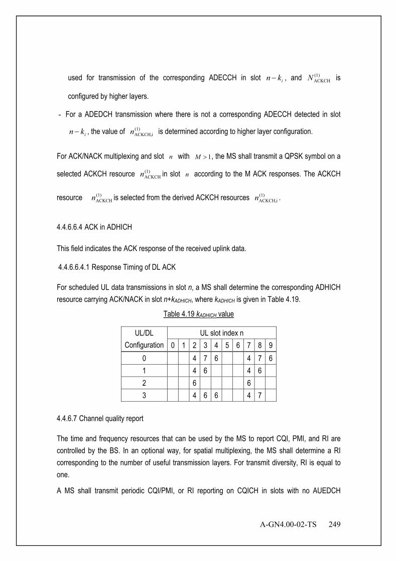
A-GN4.00-02-TS 249
used for transmission of the corresponding ADECCH in slot ikn − , and (1)ACKCHN is
configured by higher layers.
- For a ADEDCH transmission where there is not a corresponding ADECCH detected in slot
ikn − , the value of )1(iACKCH,n is determined according to higher layer configuration.
For ACK/NACK multiplexing and slot n with 1>M , the MS shall transmit a QPSK symbol on a
selected ACKCH resource )1(ACKCHn in slot n according to the M ACK responses. The ACKCH
resource )1(ACKCHn is selected from the derived ACKCH resources )1(
iACKCH,n .
4.4.6.6.4 ACK in ADHICH This field indicates the ACK response of the received uplink data. 4.4.6.6.4.1 Response Timing of DL ACK For scheduled UL data transmissions in slot n, a MS shall determine the corresponding ADHICH resource carrying ACK/NACK in slot n+kADHICH, where kADHICH is given in Table 4.19.
Table 4.19 kADHICH value
UL/DL Configuration
UL slot index n 0 1 2 3 4 5 6 7 8 9
0 4 7 6 4 7 6 1 4 6 4 6 2 6 6 3 4 6 6 4 7
4.4.6.7 Channel quality report The time and frequency resources that can be used by the MS to report CQI, PMI, and RI are controlled by the BS. In an optional way, for spatial multiplexing, the MS shall determine a RI corresponding to the number of useful transmission layers. For transmit diversity, RI is equal to one.
A MS shall transmit periodic CQI/PMI, or RI reporting on CQICH in slots with no AUEDCH

250 A-GN4.00-02-TS
allocation. A MS shall transmit periodic CQI/PMI or RI reporting on AUEDCH in slots with AUEDCH allocation. The set of subbands (S) a MS shall evaluate for CQI reporting spans the entire downlink system bandwidth. A subband is a set of k contiguous PRUs where k is a function of system bandwidth. Note the last subband in set S may have fewer than k contiguous PRUs depending on DL
RUN .
The number of subbands for system bandwidth given by DLRUN is defined by kNN /DL
RU= .
The subbands shall be indexed in the order of increasing frequency and non-increasing sizes starting at the lowest frequency. 4.4.6.7.1 CQI definition Each CQI consists of a 4-bit CQI index, which indicates a suggested modulation order and coding rate. CQI index 0 is used tor indicating out of range. Based on an unrestricted observation interval in time and frequency, the MS shall derive for each CQI value reported in uplink slot n the highest CQI index between 1 and 15, which satisfies the following condition, or CQI index 0 if CQI index 1 does not satisfy the condition:
- A single ADEDCH transport block with a combination of modulation scheme and transport block size corresponding to the CQI index, and occupying a group of downlink physical resource units termed the CQI reference resource, could be received with a transport block error probability not exceeding 0.1.
A combination of modulation scheme and transport block size corresponds to a CQI index if: - the combination could be signalled for transmission on the ADEDCH in the CQI reference
resource according to the relevant Transport Block Size table, and
- the modulation scheme is indicated by the CQI index, and
- the combination of transport block size and modulation scheme when applied to the reference resource results in the code rate which is the closest possible to the code rate indicated by the CQI index. If more than one combination of transport block size and modulation scheme results in a code rate equally close to the code rate indicated by the CQI index, only the combination with the smallest of such transport block sizes is relevant.
The CQI reference resource is defined as follows: - In the frequency domain, the CQI reference resource is defined by the group of downlink
physical resource units corresponding to the band to which the derived CQI value relates.
A-GN4.00-02-TS 251
- In the time domain, the CQI reference resource is defined by a single downlink slot n-nCQI_ref,
o where for periodic CQI reporting nCQI_ref is the smallest value greater than or equal to 4, such that it corresponds to a valid downlink slot;
A downlink slot shall be considered to be valid if: it is configured as a downlink slot for that MS, and
it does not contain a DSS field in case the length of DSS is s7680 T⋅ and less, and
it does not fall within a configured measurement gap for that MS.
If there is no valid downlink slot for the CQI reference resource, CQI reporting is omitted in uplink slot n.
- In the layer domain, the CQI reference resource is defined by any RI and PMI on which the CQI is conditioned.
4.4.6.7.2 PMI definition For AMTs 4, 5, and 6, precoding feedback is used for channel dependent codebook based precoding and relies on MSs reporting PMI. A MS shall report PMI based on the feedback modes. Each PMI value corresponds to a codebook index. For other AMTs, PMI reporting is not supported. 4.4.6.7.3 Periodic CQI/PMI/RI reporting on CQICH A MS is semi-statically configured by higher layers to periodically feed back different CQI, PMI, and RI on the CQICH. Multiple reporting modes, namely 1-0, 1-1, 2-0 and 2-1, are supported. In reporting mode 1-0, only a wideband CQI will be reported. In reporting mode 1-1, a wideband CQI and a single PMI will be reported. In reporting mode 2-0, both wideband CQI and subbamd CQI will be reported. In reporting mode 2-1, wideband CQI, subband CQI and a signle PMI will be reported. The periodic CQI reporting mode is given by the parameter cqi-FormatIndicatorPeriodic which is configured by higher-layer signalling. For subband CQI, a CQI report in a certain slot describes the channel quality in a particular part or in particular parts of the bandwidth described subsequently as bandwidth part (BP) or parts. The bandwidth parts shall be indexed in the order of increasing frequency and non-increasing sizes starting at the lowest frequency. For subband CQI, the MS selects a single subband out of

252 A-GN4.00-02-TS
jN subbands of a bandwidth part, and reports its CQI index along with a corresponding L-bit
label indexed in the order of increasing frequency, where JkNL //log DLRU2= .
Four CQI/PMI and RI reporting types with distinct periods and offsets are supported for each CQICH reporting mode:
• Type 1 report supports CQI feedback for the MS selected sub-bands • Type 2 report supports wideband CQI and PMI feedback. • Type 3 report supports RI feedback • Type 4 report supports wideband CQI
In the case where wideband CQI/PMI reporting is configured:
• The reporting instances for wideband CQI/PMI are slots satisfying
( ) 0mod2/10 , =−+× PCQIOFFSETsf NNnn , where fn is the system frame number, and
sn = {0,1,…, 19} is the half-slot index within the frame, and NOFFSET,CQI is the corresponding wideband CQI/PMI reporting offset (in slots) and NP is the wideband CQI/PMI period (in slots).
• In case RI reporting is configured, the reporting interval of the RI reporting is an integer multiple MRI of wideband CQI/PMI period NP (in slots).
o The reporting instances for RI are slots satisfying
( ) ( ) 0mod2/10 ,, =⋅−−+× RIPRIOFFSETCQIOFFSETsf MNNNnn , where NOFFSET,RI
is the corresponding relative RI offset to the wideband CQI/PMI reporting offset (in slots).
o The reporting offset for RI NOFFSET,RI takes values from the set {0, −1, …, −(NP−1)}.
o In case of collision of RI and wideband CQI/PMI the wideband CQI/PMI is dropped.
• The periodicity NP and offset NOFFSET,CQI for wideband CQI/PMI reporting are determined based on the parameter configured by higher layer signaling. The periodicity MRI, and offset NOFFSET,RI for RI reporting are determined based on the parameter configured by higher layer signalling.
In the case where both wideband CQI/PMI and subband CQI reporting are configured:

A-GN4.00-02-TS 253
• The reporting instances for wideband CQI/PMI and subband CQI are slots satisfying
( ) 0mod2/10 , =−+× PCQIOFFSETsf NNnn , where fn is the system frame number, and
sn = {0,1,…, 19} is the half-slot index within the frame, NOFFSET,CQI is the corresponding wideband CQI/PMI reporting offset (in slots) , and NP is the period of CQI/PMI reporting instance (in slots).
The wideband CQI/PMI report has period H*NP, and is reported on the slots
satisfying ( ) ( ) 0mod2/10 , =⋅−+× PCQIOFFSETsf NHNnn . The integer H is
defined as H=J*K+1, where J is the number of bandwidth parts.
Between every two consecutive wideband CQI/PMI reports, the remaining J*K reporting instances are used in sequence for subband CQI reports on K full cycles of bandwidth parts except when the gap between two consecutive wideband CQI/PMI reports contains less than J*K reporting instances due to a system frame number transition to 0, in which case the MS shall not transmit the remainder of the subband CQI reports which have not been transmitted before the second of the two wideband CQI/PMI reports. Each full cycle of bandwidth parts shall be in increasing order starting from bandwidth part 0 to bandwidth part J-1.
• In case RI reporting is configured, the reporting interval of RI is MRI times the wideband CQI/PMI period, and RI is reported on the same CQICH cyclic shift resource as both the wideband CQI/PMI and subband CQI reports.
The reporting instances for RI are slots satisfying
( ) ( ) 0mod2/10 ,, =⋅⋅−−+× RIPRIOFFSETCQIOFFSETsf MNHNNnn .
In case of collision between RI and wideband CQI/PMI or subband CQI, the wideband CQI/PMI or subband CQI is dropped.
• The parameter K is configured by higher-layer and the parameter NOFFSET,RI is selected from the set {0, -1, …,-( NP -1), - NP }.
• The periodicity NP and offset NOFFSET,CQI for CQI reporting are determined based on the parameter configured by higher layer signalling. The periodicity MRI, and offset NOFFSET,RI for RI reporting are determined based on the parameter configured by higher layer signalling.
254 A-GN4.00-02-TS
The CQI/PMI or RI report shall be transmitted on the CQICH resource which is MS specific and configured by higher layers. For periodic CQI/PMI reporting, the following periodicity values apply depending on the UL/DL configuration:
o The reporting period of NP = 1 is only applicable to UL/DL configurations 0, 1 and 3, where all UL slots in a radio frame are used for CQI/PMI reporting.
o The reporting period of NP = 5 is only applicable to UL/DL configurations 0, 1, 2 and 3.
o The reporting periods of NP = {10, 20, 40, 80, 160} are applicable to all UL/DL configurations.
A RI report in a periodic reporting mode is valid only for CQI/PMI report on that periodic reporting mode. For the calculation of CQI/PMI conditioned on the last reported RI, in the absence of a last reported RI the MS shall conduct the CQI/PMI calculation conditioned on the lowest possible RI as given by the bitmap parameter codebookSubsetRestriction . 4.4.6.8 MAP The PRU numbers are assigned as shown in Figure 4.44. This number is called logical PRU number. MAP indicates logical PRU number, which includes CCH PRU(s). As for logical PRU number, refer to section 4.1.1.2.1, 4.1.1.2.2 and .4.1.1.2.2. MAP origin indicates the starting point of the logical PRU number for the MS. BS decides MAP origin by negotiating with MS at access establishment phase.
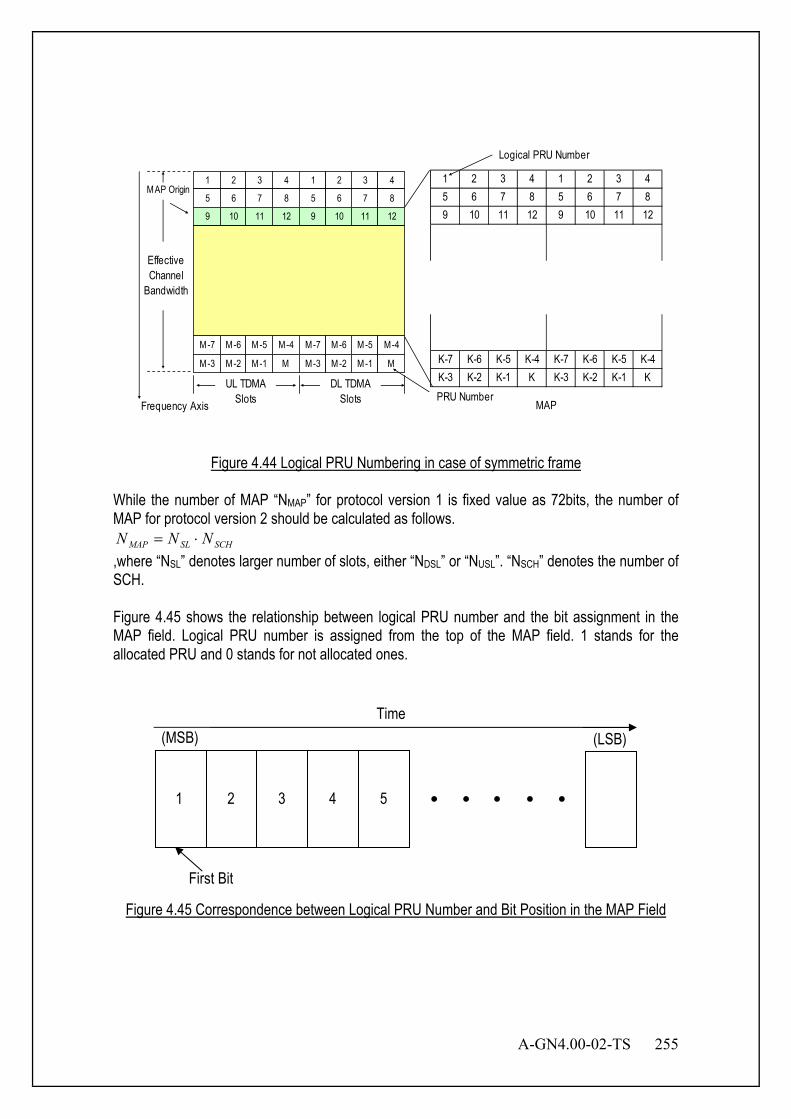
A-GN4.00-02-TS 255
1 2 3 4 1 2 3 45 6 7 8 5 6 7 89 10 11 12 9 10 11 12
K-7 K-6 K-5 K-4 K-7 K-6 K-5 K-4K-3 K-2 K-1 K K-3 K-2 K-1 K
MAPFrequency Axis
Logical PRU Number
EffectiveChannel
Bandwidth
DL TDMASlots
MAP Origin
PRU Number
1 2 3 4
5 6 7 8
9 10 11 12
M-7 M-6 M-5 M-4
M-3 M-2 M-1 M
UL TDMASlots
1 2 3 4
5 6 7 8
9 10 11 12
M-7 M-6 M-5 M-4
M-3 M-2 M-1 M
Figure 4.44 Logical PRU Numbering in case of symmetric frame
While the number of MAP “NMAP” for protocol version 1 is fixed value as 72bits, the number of MAP for protocol version 2 should be calculated as follows.
SCHSLMAP NNN ⋅= ,where “NSL” denotes larger number of slots, either “NDSL” or “NUSL”. “NSCH” denotes the number of SCH. Figure 4.45 shows the relationship between logical PRU number and the bit assignment in the MAP field. Logical PRU number is assigned from the top of the MAP field. 1 stands for the allocated PRU and 0 stands for not allocated ones.
Figure 4.45 Correspondence between Logical PRU Number and Bit Position in the MAP Field
• • • • • 1 2 3 4 5
Time
First Bit
(MSB) (LSB)

256 A-GN4.00-02-TS
4.4.6.8.1 Response Timing of MAP Figure 4.46 shows MAP indication timing. BS determines this response time for each MS by negotiating with the MS at access establishment phase. MAP field indicates the PRU which can be used as EXCH one frame after in case of (a) timing 1. It indicates the PRU which can be used as EXCH two frames after in case of (b) timing 2.
TimeDLUL
EXCH
(a) Timing 1 Allocation
5 ms
MAP
Time
ANCH
DLUL
Time
EXCH
(b) Timing 2 Allocation
5 ms
Time
ANCH
DLUL
DLUL
MAP
Figure 4.46 Example of MAP Indication Timing
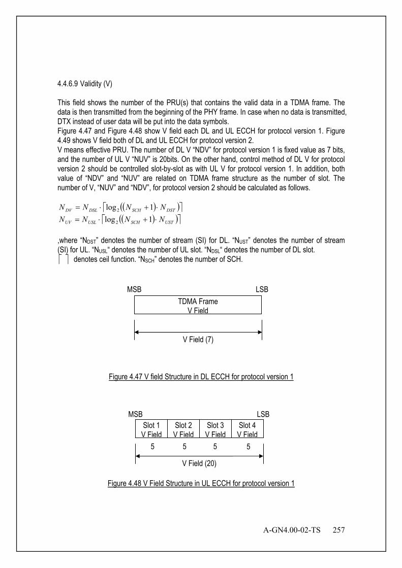
A-GN4.00-02-TS 257
4.4.6.9 Validity (V) This field shows the number of the PRU(s) that contains the valid data in a TDMA frame. The data is then transmitted from the beginning of the PHY frame. In case when no data is transmitted, DTX instead of user data will be put into the data symbols. Figure 4.47 and Figure 4.48 show V field each DL and UL ECCH for protocol version 1. Figure 4.49 shows V field both of DL and UL ECCH for protocol version 2. V means effective PRU. The number of DL V “NDV” for protocol version 1 is fixed value as 7 bits, and the number of UL V “NUV” is 20bits. On the other hand, control method of DL V for protocol version 2 should be controlled slot-by-slot as with UL V for protocol version 1. In addition, both value of “NDV” and “NUV” are related on TDMA frame structure as the number of slot. The number of V, “NUV” and “NDV”, for protocol version 2 should be calculated as follows.
( )( ) DSTSCHDSLDV NNNN ⋅+⋅= 1log2 ( )( ) USTSCHUSLUV NNNN ⋅+⋅= 1log2
,where “NDST” denotes the number of stream (SI) for DL. “NUST” denotes the number of stream (SI) for UL. “NUSL“ denotes the number of UL slot. “NDSL“ denotes the number of DL slot. denotes ceil function. “NSCH” denotes the number of SCH.
Figure 4.47 V field Structure in DL ECCH for protocol version 1
Figure 4.48 V Field Structure in UL ECCH for protocol version 1
TDMA Frame V Field
V Field (7)
MSB LSB
Slot 1 V Field
V Field (20)
Slot 2 V Field
Slot 3 V Field
Slot 4 V Field
MSB LSB
5 5 5 5
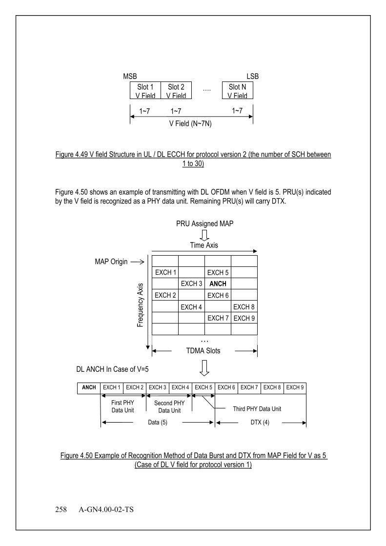
258 A-GN4.00-02-TS
Figure 4.49 V field Structure in UL / DL ECCH for protocol version 2 (the number of SCH between 1 to 30)
Figure 4.50 shows an example of transmitting with DL OFDM when V field is 5. PRU(s) indicated by the V field is recognized as a PHY data unit. Remaining PRU(s) will carry DTX.
Figure 4.50 Example of Recognition Method of Data Burst and DTX from MAP Field for V as 5
(Case of DL V field for protocol version 1)
EXCH 1 EXCH 5 EXCH 3
EXCH 2 EXCH 6 EXCH 4 EXCH 8
EXCH 7 EXCH 9
ANCH
Time Axis
PRU Assigned MAP
Freq
uenc
y Axis
MAP Origin
DL ANCH In Case of V=5
TDMA Slots
Second PHY Data Unit
DTX (4)
Third PHY Data Unit
Data (5)
First PHY Data Unit
…
Slot 1 V Field
V Field (N~7N)
Slot 2 V Field
…. Slot N V Field
MSB LSB
1~7 1~7 1~7
ANCH EXCH 3 EXCH 4 EXCH 5 EXCH 6 EXCH 7 EXCH 8 EXCH 9 EXCH 1 EXCH 2
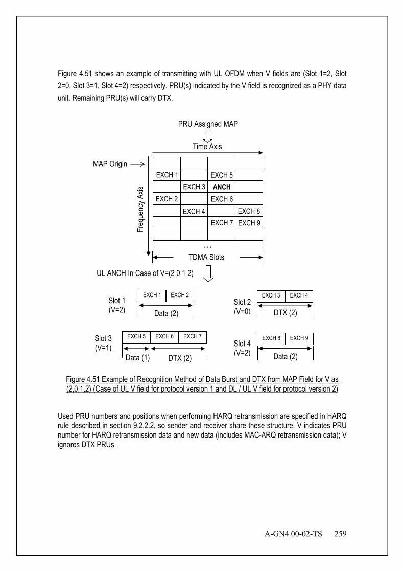
A-GN4.00-02-TS 259
Figure 4.51 shows an example of transmitting with UL OFDM when V fields are (Slot 1=2, Slot 2=0, Slot 3=1, Slot 4=2) respectively. PRU(s) indicated by the V field is recognized as a PHY data unit. Remaining PRU(s) will carry DTX.
Figure 4.51 Example of Recognition Method of Data Burst and DTX from MAP Field for V as (2,0,1,2) (Case of UL V field for protocol version 1 and DL / UL V field for protocol version 2)
Used PRU numbers and positions when performing HARQ retransmission are specified in HARQ rule described in section 9.2.2.2, so sender and receiver share these structure. V indicates PRU number for HARQ retransmission data and new data (includes MAC-ARQ retransmission data); V ignores DTX PRUs.
UL ANCH In Case of V=(2 0 1 2)
EXCH 1 EXCH 5 EXCH 3
EXCH 2 EXCH 6 EXCH 4 EXCH 8
EXCH 7 EXCH 9
ANCH
Time Axis
PRU Assigned MAP
Freq
uenc
y Axis
MAP Origin
TDMA Slots …
Slot 1 (V=2) Data (2)
EXCH 1 EXCH 2 Slot 2 (V=0)
EXCH 3 EXCH 4
DTX (2)
Data (1) DTX (2)
Slot 3 (V=1)
EXCH 6 EXCH 7 EXCH 5 Slot 4 (V=2) Data (2)
EXCH 8 EXCH 9
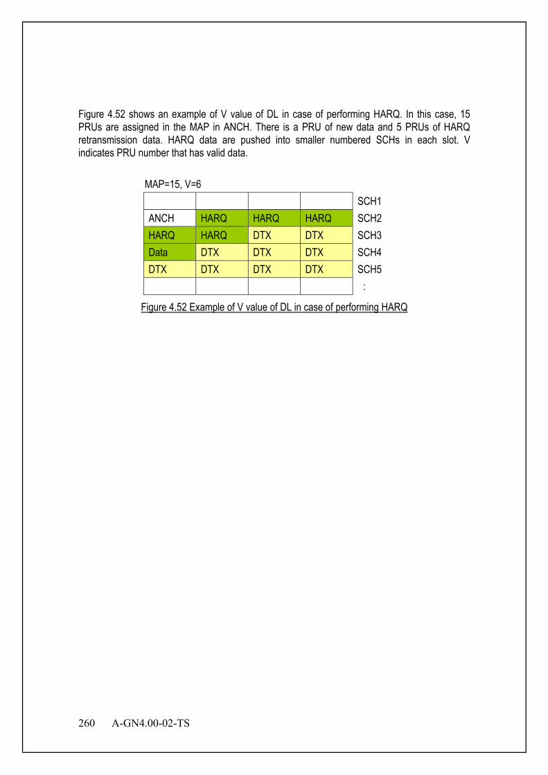
260 A-GN4.00-02-TS
Figure 4.52 shows an example of V value of DL in case of performing HARQ. In this case, 15 PRUs are assigned in the MAP in ANCH. There is a PRU of new data and 5 PRUs of HARQ retransmission data. HARQ data are pushed into smaller numbered SCHs in each slot. V indicates PRU number that has valid data.
MAP=15, V=6 SCH1 ANCH HARQ HARQ HARQ SCH2 HARQ HARQ DTX DTX SCH3 Data DTX DTX DTX SCH4 DTX DTX DTX DTX SCH5 :
Figure 4.52 Example of V value of DL in case of performing HARQ
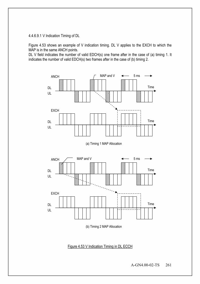
A-GN4.00-02-TS 261
4.4.6.9.1 V Indication Timing of DL Figure 4.53 shows an example of V indication timing. DL V applies to the EXCH to which the MAP is in the same ANCH points. DL V field indicates the number of valid EDCH(s) one frame after in the case of (a) timing 1. It indicates the number of valid EDCH(s) two frames after in the case of (b) timing 2.
TimeDLUL
EXCH
(a) Timing 1 MAP Allocation
MAP and V 5 ms
Time
ANCH
Time
EXCH
(b) Timing 2 MAP Allocation
MAP and V 5 ms
Time
ANCH
DLUL
DLUL
DLUL
Figure 4.53 V Indication Timing in DL ECCH
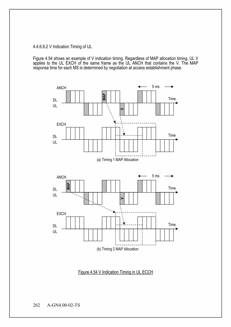
262 A-GN4.00-02-TS
4.4.6.9.2 V Indication Timing of UL Figure 4.54 shows an example of V indication timing. Regardless of MAP allocation timing, UL V applies to the UL EXCH of the same frame as the UL ANCH that contains the V. The MAP response time for each MS is determined by negotiation at access establishment phase.
TimeDLUL
EXCH
(a) Timing 1 MAP Allocation
5 ms
MAP
Time
ANCH
Time
EXCH
(b) Timing 2 MAP Allocation
5 ms
Time
ANCH
DLUL
DLUL
DLUL
V
MAP
V
Figure 4.54 V Indication Timing in UL ECCH

A-GN4.00-02-TS 263
4.4.6.10 HARQ Cancel (HC) This field indicates cancellation of HARQ. HARQ can be activated when some conditions are fulfilled. MS or BS received set-to-1 HC field, cancels the HARQ process. Refer to Section 4.4.3.2.1.
Table 4.20 Value of HC Field
HC Value Description 0 HARQ Enable 1 HARQ Cancel
4.4.6.10.1 HC Indication Timing of DL Figure 4.55 shows an example of HC indication timing. DL HC applies to the EXCH to which the MAP is in the same ANCH points. DL HC field indicates whether HARQ one frame later is valid or not in case of (a) timing 1. It indicates whether HARQ two frames later is valid or not in case of (b) timing 2.
TimeDLUL
EXCH
(a) Timing 1 MAP Allocation
MAP and HC 5 ms
Time
ANCH
DLUL

264 A-GN4.00-02-TS
Time
EXCH
(b) Timing 2 MAP Allocation
MAP and HC 5 ms
Time
ANCH
DLUL
DLUL
Figure 4.55 HC Indication Timing in DL ECCH
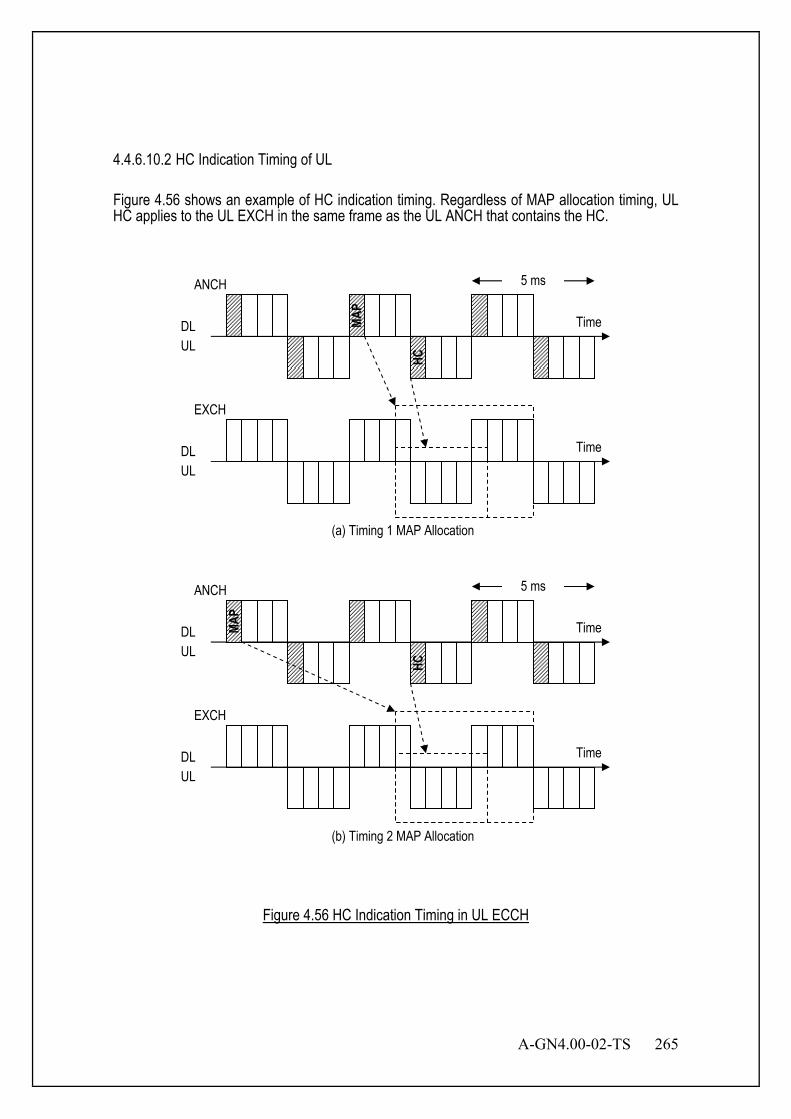
A-GN4.00-02-TS 265
4.4.6.10.2 HC Indication Timing of UL Figure 4.56 shows an example of HC indication timing. Regardless of MAP allocation timing, UL HC applies to the UL EXCH in the same frame as the UL ANCH that contains the HC.
TimeDLUL
EXCH
(a) Timing 1 MAP Allocation
5 ms
MAP
Time
ANCH
Time
EXCH
(b) Timing 2 MAP Allocation
5 ms
Time
ANCH
DLUL
DLUL
DLUL
HC
MAP
HC
Figure 4.56 HC Indication Timing in UL ECCH

266 A-GN4.00-02-TS
4.4.6.11 Request Channel (RCH) This field is used for the bandwidth allocation request or transmission power margin notification from the MS to BS. The type of content is distinguished by identifier in RCH field. MS informs BS of data size to be sent. Figure 4.57 shows structure of the RCH field.
Bit 7 6 5 4 3 2 1 Identifier Data
Figure 4.57 RCH field
Table 4.21 Value of Identifier Field
Bit Data Identifier of RCH Field 7 6 0 0 UL Data Size Notification 0 1 Transmission Power Margin Notification 1 0 Reserved 1 1 Reserved
4.4.6.11.1 UL Data Size Notification
Figure 4.58 shows UL Data Size Notification format. This field is used for the bandwidth allocation request from the MS to BS. MS informs BS of data size to be sent.
Bit 7 6 5 4 3 2 1
0 0 Unit Data Length
Figure 4.58 UL Data Size Notification
Table 4.22 Unit Field
Unit Bit 5 4 0 0 MAC layer control message 0 1 100 bytes 1 0 1 kbytes 1 1 10 kbytes
For example, Unit=”0 1” (100 bytes), Data Length=”1 0 0” then it indicates 400 bytes. Note that it does not show accurate value.

A-GN4.00-02-TS 267
4.4.6.11.2 Transmission Power Margin Notification Figure 4.59 shows Transmission Power Margin Notification format. This field is used for the notification of transmission power margin from MS to BS. BS may refer to this value when BS allocates PRU.
Bit 7 6 5 4 3 2 1
0 1 Transmission Power Margin
Notification
Figure 4.59 Transmission Power Margin Notification
Table 4.23 Transmission Power Margin Notification
Bit 5 4 3 2 1 0 0 0 0 0 0 dB 0 0 0 0 1 1 dB 0 0 0 1 0 2 dB : 1 1 1 1 1 31 dB
4.4.6.12 Request Channel (RCH) Request Channel (RCH) is allocated in MSL1(MSL1). 4.4.6.12.1 Optional UL Data Size Notification UL Data Size Notification MSL1 control elements consist of either: Short UL Data Size Notification and Truncated UL Data Size Notification format : one FCG ID field and one corresponding UL Data Size (Figure 4.60); or Long UL Data Size Notification format : four UL Data Size, corresponding to FCG IDs #0 through #3 (Figure 4.61). The UL Data Size Notification formats are identified by MSL1 PDU subheaders with FCIDs as specified in Table 4.58. The fields FCG ID and UL Data Size are defined as follow:
- FCG ID: The function Channel Group ID field identifies the group of function channel(s) which UL Data Size is being reported. The length of the field is 2 bits;
- UL Data Size: The UL Data Size field identifies the total amount of data available across all function channels of a function channel group after the MSL1 PDU has been built. The amount of data is indicated in number of bytes. The length of this field is 6 bits.

268 A-GN4.00-02-TS
Figure 4.60: Short UL Data Size Notification and Truncated UL Data Size Notification MSL1 control element
Figure 4.61:Long UL Data Size Notification MSL1 control element
4.4.6.12.2 Advanced Transmission Power Margin Notification (ATPMN) Report The ATPMN MSL1 control element is identified by a MSL1 PDU subheader with FCID as specified in Table 4.58. It has a fixed size and consists of a single octet defined as follows (Figure 4.62):
- R: reserved bit, set to "0";
- Power Margin (PM): this field indicates the power margin level. The length of the field is 6 bits. The reported PM and the corresponding margin levels are shown in Table 4.24 below.
Figure 4.62: ATPMN MSL1 control element
Table 4.24: Power Margin Levels for ATPMN
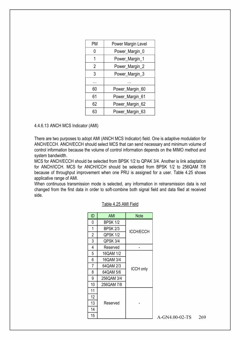
A-GN4.00-02-TS 269
PM Power Margin Level 0 Power_Margin_0 1 Power_Margin_1 2 Power_Margin_2 3 Power_Margin_3 … … 60 Power_Margin_60 61 Power_Margin_61 62 Power_Margin_62 63 Power_Margin_63
4.4.6.13 ANCH MCS Indicator (AMI) There are two purposes to adopt AMI (ANCH MCS Indicator) field. One is adaptive modulation for ANCH/ECCH. ANCH/ECCH should select MCS that can send necessary and minimum volume of control information because the volume of control information depends on the MIMO method and system bandwidth. MCS for ANCH/ECCH should be selected from BPSK 1/2 to QPAK 3/4. Another is link adaptation for ANCH/ICCH. MCS for ANCH/ICCH should be selected from BPSK 1/2 to 256QAM 7/8 because of throughput improvement when one PRU is assigned for a user. Table 4.25 shows applicative range of AMI. When continuous transmission mode is selected, any information in retransmission data is not changed from the first data in order to soft-combine both signal field and data filed at received side.
Table 4.25 AMI Field
ID AMI Note0 BPSK 1/21 BPSK 2/32 QPSK 1/23 QPSK 3/44 Reserved -5 16QAM 1/26 16QAM 3/47 64QAM 2/38 64QAM 5/69 256QAM 3/4
10 256QAM 7/81112131415
ICCH only
Reserved -
ICCH/ECCH
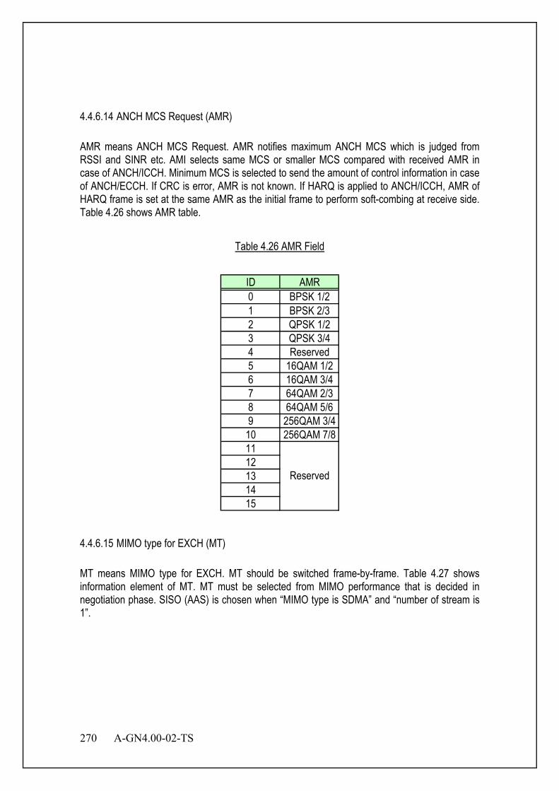
270 A-GN4.00-02-TS
4.4.6.14 ANCH MCS Request (AMR) AMR means ANCH MCS Request. AMR notifies maximum ANCH MCS which is judged from RSSI and SINR etc. AMI selects same MCS or smaller MCS compared with received AMR in case of ANCH/ICCH. Minimum MCS is selected to send the amount of control information in case of ANCH/ECCH. If CRC is error, AMR is not known. If HARQ is applied to ANCH/ICCH, AMR of HARQ frame is set at the same AMR as the initial frame to perform soft-combing at receive side. Table 4.26 shows AMR table.
Table 4.26 AMR Field
ID AMR0 BPSK 1/21 BPSK 2/32 QPSK 1/23 QPSK 3/44 Reserved5 16QAM 1/26 16QAM 3/47 64QAM 2/38 64QAM 5/69 256QAM 3/4
10 256QAM 7/81112131415
Reserved
4.4.6.15 MIMO type for EXCH (MT) MT means MIMO type for EXCH. MT should be switched frame-by-frame. Table 4.27 shows information element of MT. MT must be selected from MIMO performance that is decided in negotiation phase. SISO (AAS) is chosen when “MIMO type is SDMA” and “number of stream is 1”.
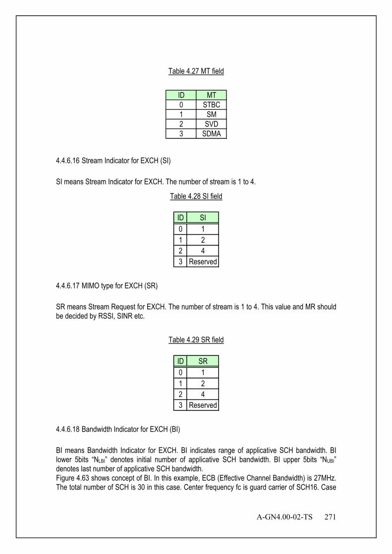
A-GN4.00-02-TS 271
Table 4.27 MT field
ID MT0 STBC1 SM2 SVD3 SDMA
4.4.6.16 Stream Indicator for EXCH (SI) SI means Stream Indicator for EXCH. The number of stream is 1 to 4.
Table 4.28 SI field
ID SI0 11 22 43 Reserved
4.4.6.17 MIMO type for EXCH (SR) SR means Stream Request for EXCH. The number of stream is 1 to 4. This value and MR should be decided by RSSI, SINR etc.
Table 4.29 SR field
ID SR0 11 22 43 Reserved
4.4.6.18 Bandwidth Indicator for EXCH (BI) BI means Bandwidth Indicator for EXCH. BI indicates range of applicative SCH bandwidth. BI lower 5bits “NLBI” denotes initial number of applicative SCH bandwidth. BI upper 5bits “NUBI” denotes last number of applicative SCH bandwidth. Figure 4.63 shows concept of BI. In this example, ECB (Effective Channel Bandwidth) is 27MHz. The total number of SCH is 30 in this case. Center frequency fc is guard carrier of SCH16. Case
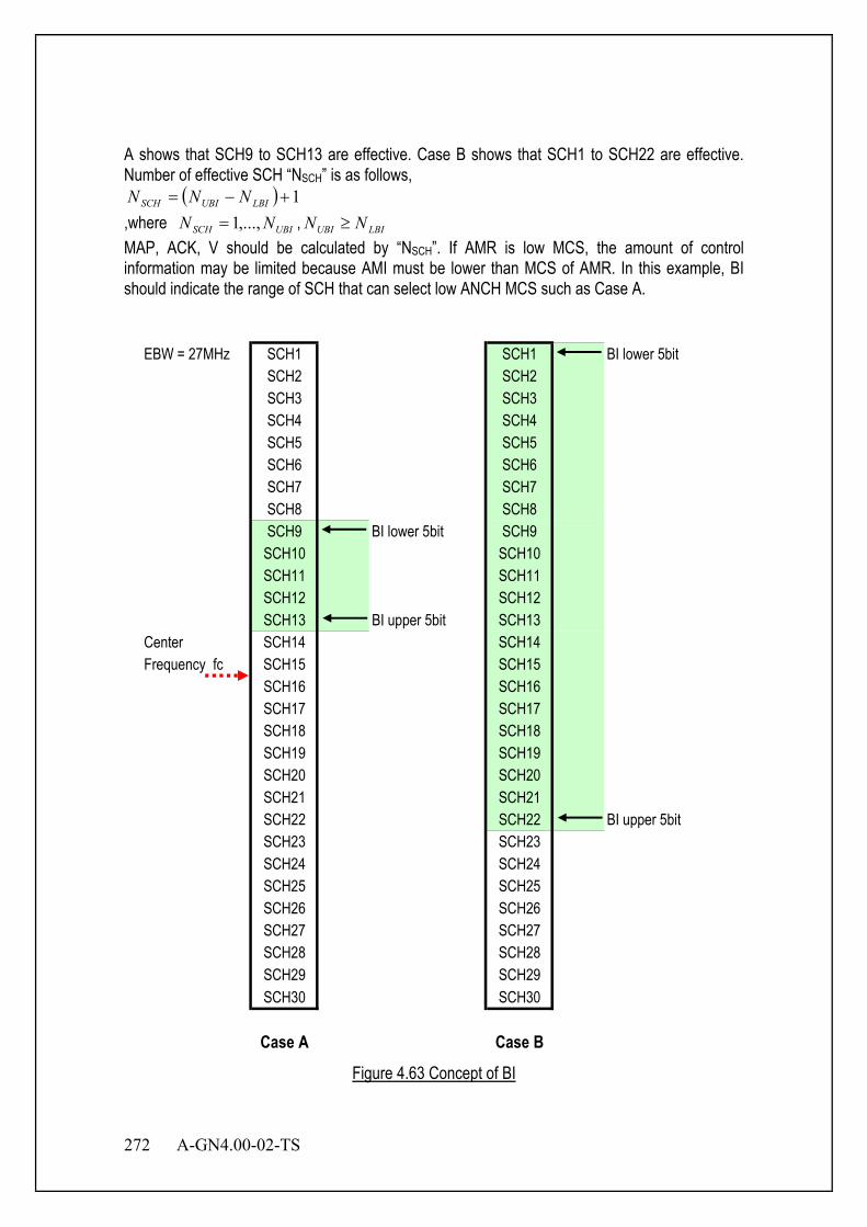
272 A-GN4.00-02-TS
A shows that SCH9 to SCH13 are effective. Case B shows that SCH1 to SCH22 are effective. Number of effective SCH “NSCH” is as follows,
( ) 1+−= LBIUBISCH NNN ,where UBISCH NN ,...,1= , LBIUBI NN ≥ MAP, ACK, V should be calculated by “NSCH”. If AMR is low MCS, the amount of control information may be limited because AMI must be lower than MCS of AMR. In this example, BI should indicate the range of SCH that can select low ANCH MCS such as Case A.
EBW = 27MHz SCH1 SCH1 BI lower 5bitSCH2 SCH2SCH3 SCH3SCH4 SCH4SCH5 SCH5SCH6 SCH6SCH7 SCH7SCH8 SCH8SCH9 BI lower 5bit SCH9
SCH10 SCH10SCH11 SCH11SCH12 SCH12SCH13 BI upper 5bit SCH13
Center SCH14 SCH14Frequency fc SCH15 SCH15
SCH16 SCH16SCH17 SCH17SCH18 SCH18SCH19 SCH19SCH20 SCH20SCH21 SCH21SCH22 SCH22 BI upper 5bitSCH23 SCH23SCH24 SCH24SCH25 SCH25SCH26 SCH26SCH27 SCH27SCH28 SCH28SCH29 SCH29SCH30 SCH30
Case A Case B Figure 4.63 Concept of BI
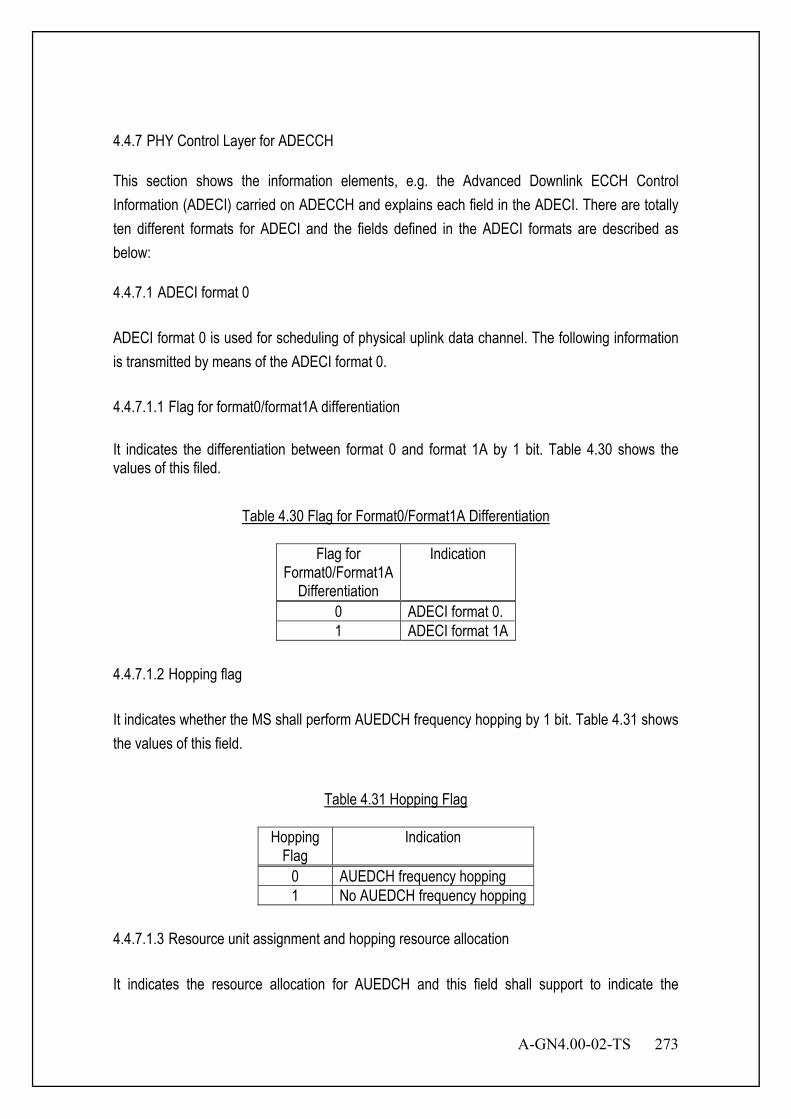
A-GN4.00-02-TS 273
4.4.7 PHY Control Layer for ADECCH This section shows the information elements, e.g. the Advanced Downlink ECCH Control Information (ADECI) carried on ADECCH and explains each field in the ADECI. There are totally ten different formats for ADECI and the fields defined in the ADECI formats are described as below: 4.4.7.1 ADECI format 0 ADECI format 0 is used for scheduling of physical uplink data channel. The following information is transmitted by means of the ADECI format 0. 4.4.7.1.1 Flag for format0/format1A differentiation It indicates the differentiation between format 0 and format 1A by 1 bit. Table 4.30 shows the values of this filed.
Table 4.30 Flag for Format0/Format1A Differentiation
Flag for Format0/Format1A
Differentiation
Indication
0 ADECI format 0. 1 ADECI format 1A
4.4.7.1.2 Hopping flag It indicates whether the MS shall perform AUEDCH frequency hopping by 1 bit. Table 4.31 shows the values of this field.
Table 4.31 Hopping Flag
Hopping Flag
Indication
0 AUEDCH frequency hopping 1 No AUEDCH frequency hopping
4.4.7.1.3 Resource unit assignment and hopping resource allocation It indicates the resource allocation for AUEDCH and this field shall support to indicate the
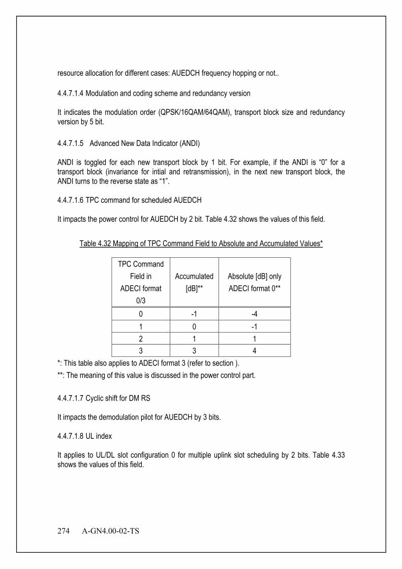
274 A-GN4.00-02-TS
resource allocation for different cases: AUEDCH frequency hopping or not.. 4.4.7.1.4 Modulation and coding scheme and redundancy version It indicates the modulation order (QPSK/16QAM/64QAM), transport block size and redundancy version by 5 bit. 4.4.7.1.5 Advanced New Data Indicator (ANDI) ANDI is toggled for each new transport block by 1 bit. For example, if the ANDI is “0” for a transport block (invariance for intial and retransmission), in the next new transport block, the ANDI turns to the reverse state as “1”. 4.4.7.1.6 TPC command for scheduled AUEDCH It impacts the power control for AUEDCH by 2 bit. Table 4.32 shows the values of this field.
Table 4.32 Mapping of TPC Command Field to Absolute and Accumulated Values*
TPC Command Field in
ADECI format 0/3
Accumulated [dB]**
Absolute [dB] only ADECI format 0**
0 -1 -4 1 0 -1 2 1 1 3 3 4
*: This table also applies to ADECI format 3 (refer to section ). **: The meaning of this value is discussed in the power control part. 4.4.7.1.7 Cyclic shift for DM RS It impacts the demodulation pilot for AUEDCH by 3 bits. 4.4.7.1.8 UL index It applies to UL/DL slot configuration 0 for multiple uplink slot scheduling by 2 bits. Table 4.33 shows the values of this field.
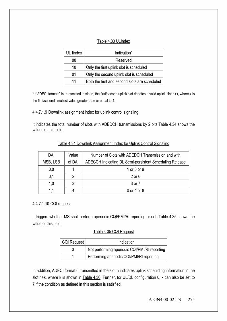
A-GN4.00-02-TS 275
Table 4.33 ULIndex
UL Iindex Indication* 00 Reserved 10 Only the first uplink slot is scheduled 01 Only the second uplink slot is scheduled 11 Both the first and second slots are scheduled
* if ADECI format 0 is transmitted in slot n, the first/second uplink slot denotes a valid uplink slot n+x, where x is the first/second smallest value greater than or equal to 4. 4.4.7.1.9 Downlink assignment index for uplink control signaling It indicates the total number of slots with ADEDCH transmissions by 2 bits.Table 4.34 shows the values of this field.
Table 4.34 Downlink Assignment Index for Uplink Control Signaling
DAI MSB, LSB
Value of DAI
Number of Slots with ADEDCH Transmission and with ADECCH Indicating DL Semi-persistent Scheduling Release
0,0 1 1 or 5 or 9 0,1 2 2 or 6 1,0 3 3 or 7 1,1 4 0 or 4 or 8
4.4.7.1.10 CQI request It triggers whether MS shall perform aperiodic CQI/PMI/RI reporting or not. Table 4.35 shows the value of this field.
Table 4.35 CQI Request
CQI Request Indication 0 Not performing aperiodic CQI/PMI/RI reporting 1 Performing aperiodic CQI/PMI/RI reporting
In addition, ADECI format 0 transmitted in the slot n indicates uplink scheulding information in the slot n+k, where k is shown in Table 4.36. Further, for UL/DL configuration 0, k can also be set to 7 if the condition as defined in this section is satisfied.

276 A-GN4.00-02-TS
Table 4.36 value k
UL/DL Configuration
DL Slot Number n 0 1 2 3 4 5 6 7 8 9
0 4 6 4 6 1 6 4 6 4 2 4 4 3 7 7 7 7 5
4.4.7.2 ADECI format 1 ADECI format 1 carries DL scheduling information for SIMO with bitmap resource allocation indication. The following information is transmitted by means of the ADECI format 1. 4.4.7.2.1 Resource allocation header It indicates whether resource allocation type 0 or type 1 applies for ADEDCH by 1 bit.. Table 4.37 shows the values of this filed.
Table 4.37 Resource Allocation Header
Resource Allocation Header
Indication
0 Resource allocation type 0 1 Resource allocation type 1
4.4.7.2.2 Resource unit assignment It indicates the resource unit assignment for ADEDCH and shall support both the resource allocation for type 0 and type 1. 4.4.7.2.3 Modulation and coding scheme It indicates the modulation order and transport block size for ADEDCH by 5 bits. 4.4.7.2.4 HARQ process number It indicates the Hybrid-ARQ process number for ADEDCH by 4 bits.

A-GN4.00-02-TS 277
4.4.7.2.5 ANDI Refer to section 4.4.7.1.5. 4.4.7.2.6 Redundancy version It indicates the redundancy version index for ADEDCH by 2 bits respectively corresponding to redundancy version 0/1/2/3. 4.4.7.2.7 TPC command for AUANCH It impacts the transmission power of AUANCH with 2 bits. Table 4.38 shows the values of this filed.
Table 4.38 Mapping of TPC Command for AUANCH
TPC Command Field in ADECI format
1A/1B/1D/1/2A/2/3
Adiusted Power [dB]
0 -1
1 0
2 1
3 3
4.4.7.2.8 Downlink assignment index in downlink control signalling It indicates the accumulative number of assigned ADEDCH transmission with corresponding ADECCH(s) up to the present slot transmitted to the corresponding MS within all the M slot(s) and applies for detection of missing DL grants for optional UL/DL slot configuration 1-3 by 2 bits. 4.4.7.3 ADECI format 1A ADECI format 1A carries DL scheduling information for SIMO with compacted resource allocation indication and it shall support the transmission of the downlink paging, ATCCH response and dynamic ABCCH information scheduling. The following information is transmitted by means of the ADECI format 1A scrambling with C-MSID. 4.4.7.3.1 Flag for format0/format1A differentiation
278 A-GN4.00-02-TS
Refer to section 4.4.7.1.1. 4.4.7.3.2 Localized/Distributed VRU assignment flag It indicates whether localized virtual resource units or distributed virtual resource units are assigned for ADEDCH: value 0 indicates localized and value 1 indicates distributed VRU assignment. 4.4.7.3.3 Resource unit assignment It indicates DL contiguous RUs assignment and shall support for Localized/Distributed VRU assignment. 4.4.7.3.4 Modulation and coding scheme Refer to section 4.4.7.2.3. 4.4.7.3.5 HARQ process number Refer to section 4.4.7.2.4. 4.4.7.3.6 ANDI Refer to section 4.4.7.1.5. 4.4.7.3.7 Redundancy version Refer to section 4.4.7.2.6. 4.4.7.3.8 TPC command for AUANCH Refer to section 4.4.7.2.7. 4.4.7.3.9 Downlink Assignment Index for downlink control signalling Refer to section 4.4.7.2.8. In addition, the information elements “access sequence index for ATCCH (by 6 bits)” and “mask index for ATCCH (by 4 bits)” shall be supported in this ADECI format to support the transmission
A-GN4.00-02-TS 279
of ATCCH. 4.4.7.4 ADECI format 1B ADECI format 1B carries DL scheduling information for closed-loop signal-rank SU-MIMO with possibly contiguous resource allocation. The following information is transmitted by means of the ADECI format 1B. 4.4.7.4.1 Localized/Distributed VRU assignment flag Refer to section 4.4.7.3.2. 4.4.7.4.2 Resource unit assignment Refer to section 4.4.7.3.3. 4.4.7.4.3 Modulation and coding scheme Refer to section 4.4.7.2.3. 4.4.7.4.4 HARQ process number Refer to section 4.4.7.2.4. 4.4.7.4.5 ANDI Refer to section 4.4.7.1.5. 4.4.7.4.6 Redundancy version Refer to section 4.4.7.2.6. 4.4.7.4.7 TPC command for AUANCH Refer to section 4.4.7.2.7. 4.4.7.4.8 Downlink Assignment Index for downlink control signalling Refer to section 4.4.7.2.8.
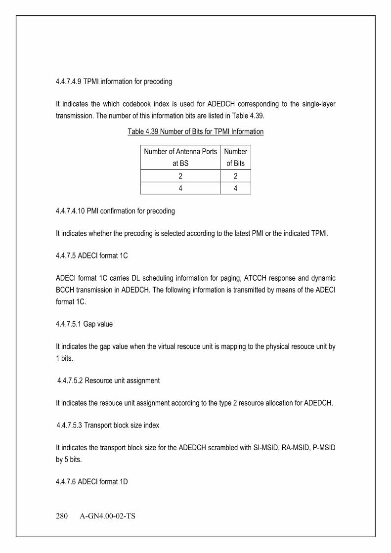
280 A-GN4.00-02-TS
4.4.7.4.9 TPMI information for precoding It indicates the which codebook index is used for ADEDCH corresponding to the single-layer transmission. The number of this information bits are listed in Table 4.39.
Table 4.39 Number of Bits for TPMI Information
Number of Antenna Ports at BS
Number of Bits
2 2 4 4
4.4.7.4.10 PMI confirmation for precoding It indicates whether the precoding is selected according to the latest PMI or the indicated TPMI. 4.4.7.5 ADECI format 1C ADECI format 1C carries DL scheduling information for paging, ATCCH response and dynamic BCCH transmission in ADEDCH. The following information is transmitted by means of the ADECI format 1C. 4.4.7.5.1 Gap value It indicates the gap value when the virtual resouce unit is mapping to the physical resouce unit by 1 bits. 4.4.7.5.2 Resource unit assignment It indicates the resouce unit assignment according to the type 2 resource allocation for ADEDCH. 4.4.7.5.3 Transport block size index It indicates the transport block size for the ADEDCH scrambled with SI-MSID, RA-MSID, P-MSID by 5 bits. 4.4.7.6 ADECI format 1D
A-GN4.00-02-TS 281
ADECI format 1D carries DL scheduling information for MU-MIMO with compacted resource allocation indication. The following information is transmitted by means of the ADECI format 1D. 4.4.7.6.1 Localized/Distributed VRU assignment flag Refer to section 4.4.7.3.2. 4.4.7.6.2 Resource unit assignment Refer to section 4.4.7.3.3. 4.4.7.6.3 Modulation and coding scheme Refer to section 4.4.7.2.3. 4.4.7.6.4 HARQ process number Refer to section 4.4.7.2.4. 4.4.7.6.5 ANDI Refer to section 4.4.7.1.5. 4.4.7.6.6 Redundancy version Refer to section 4.4.7.2.6. 4.4.7.6.7 TPC command for AUANCH Refer to section 4.4.7.2.7. 4.4.7.6.8 Downlink assignment index for DL control signaling Refer to section 4.4.7.2.8. 4.4.7.6.9 TPMI information for precoding Refer to section 4.4.7.4.9.
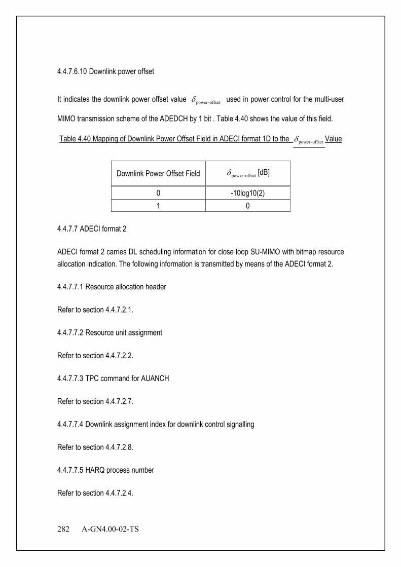
282 A-GN4.00-02-TS
4.4.7.6.10 Downlink power offset
It indicates the downlink power offset value offset-powerδ used in power control for the multi-user
MIMO transmission scheme of the ADEDCH by 1 bit . Table 4.40 shows the value of this field.
Table 4.40 Mapping of Downlink Power Offset Field in ADECI format 1D to the offset-powerδ Value
Downlink Power Offset Field offset-powerδ [dB]
0 -10log10(2) 1 0
4.4.7.7 ADECI format 2 ADECI format 2 carries DL scheduling information for close loop SU-MIMO with bitmap resource allocation indication. The following information is transmitted by means of the ADECI format 2. 4.4.7.7.1 Resource allocation header Refer to section 4.4.7.2.1. 4.4.7.7.2 Resource unit assignment Refer to section 4.4.7.2.2. 4.4.7.7.3 TPC command for AUANCH Refer to section 4.4.7.2.7. 4.4.7.7.4 Downlink assignment index for downlink control signalling Refer to section 4.4.7.2.8. 4.4.7.7.5 HARQ process number Refer to section 4.4.7.2.4.
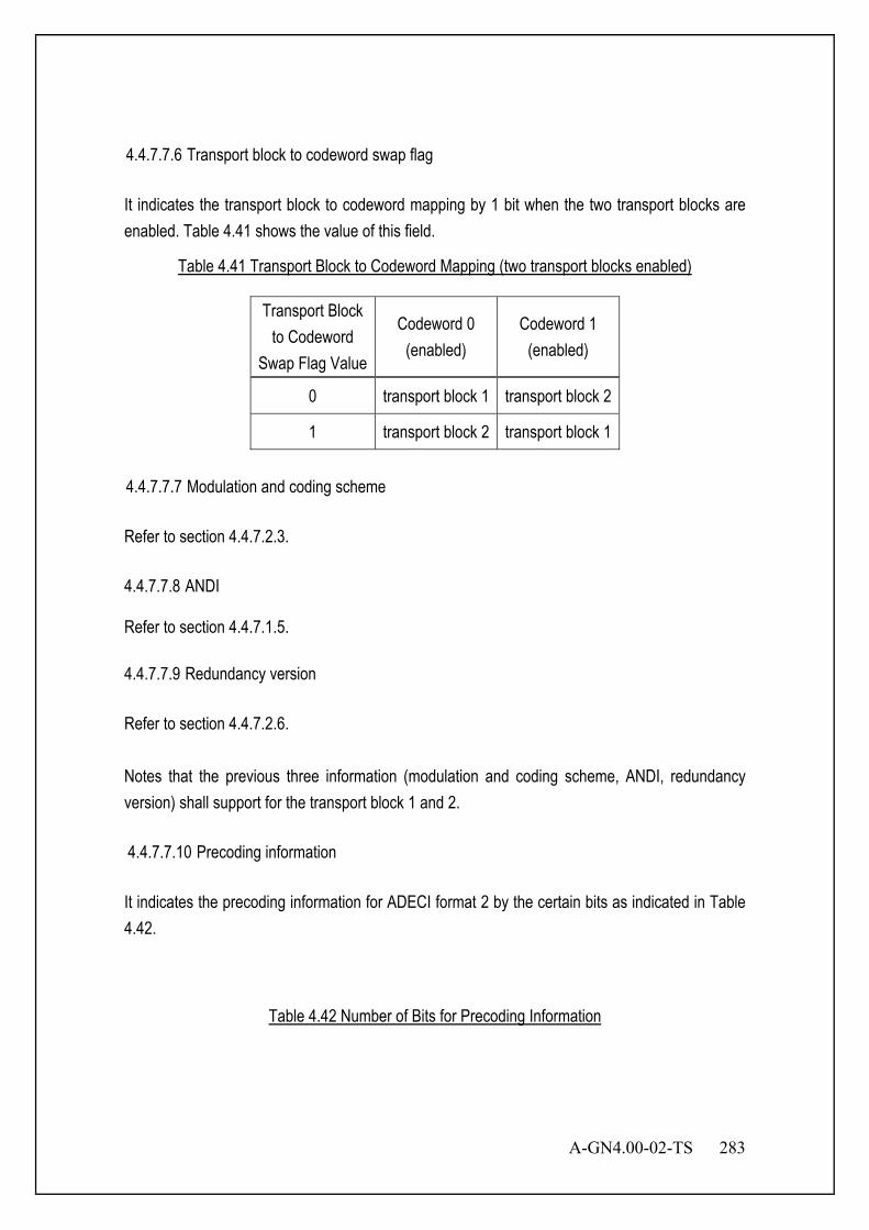
A-GN4.00-02-TS 283
4.4.7.7.6 Transport block to codeword swap flag It indicates the transport block to codeword mapping by 1 bit when the two transport blocks are enabled. Table 4.41 shows the value of this field.
Table 4.41 Transport Block to Codeword Mapping (two transport blocks enabled)
Transport Block to Codeword
Swap Flag Value
Codeword 0 (enabled)
Codeword 1 (enabled)
0 transport block 1 transport block 2
1 transport block 2 transport block 1
4.4.7.7.7 Modulation and coding scheme Refer to section 4.4.7.2.3. 4.4.7.7.8 ANDI Refer to section 4.4.7.1.5. 4.4.7.7.9 Redundancy version Refer to section 4.4.7.2.6. Notes that the previous three information (modulation and coding scheme, ANDI, redundancy version) shall support for the transport block 1 and 2. 4.4.7.7.10 Precoding information It indicates the precoding information for ADECI format 2 by the certain bits as indicated in Table 4.42.
Table 4.42 Number of Bits for Precoding Information

284 A-GN4.00-02-TS
Number of Antenna Ports at BS Number of Bits for Precoding Information 2 3 4 6
4.4.7.8 ADECI format 2A ADECI format 2A carries DL scheduling information for open loop SU-MIMO with bitmap resource allocation indication. The following information is transmitted by means of the ADECI format 2A. 4.4.7.8.1 Resource allocation header Refer to section 4.4.7.2.1. 4.4.7.8.2 Resource unit assignment Refer to section 4.4.7.2.2. 4.4.7.8.3 TPC command for AUANCH Refer to section 4.4.7.2.7. 4.4.7.8.4 Downlink assignment index for downlink control signalling Refer to section 4.4.7.2.8. 4.4.7.8.5 HARQ process number Refer to section 4.4.7.2.4. 4.4.7.8.6 Transport block to codeword swap flag Refer to section 4.4.7.7.6. 4.4.7.8.7 Modulation and coding scheme Refer to section 4.4.7.2.3.
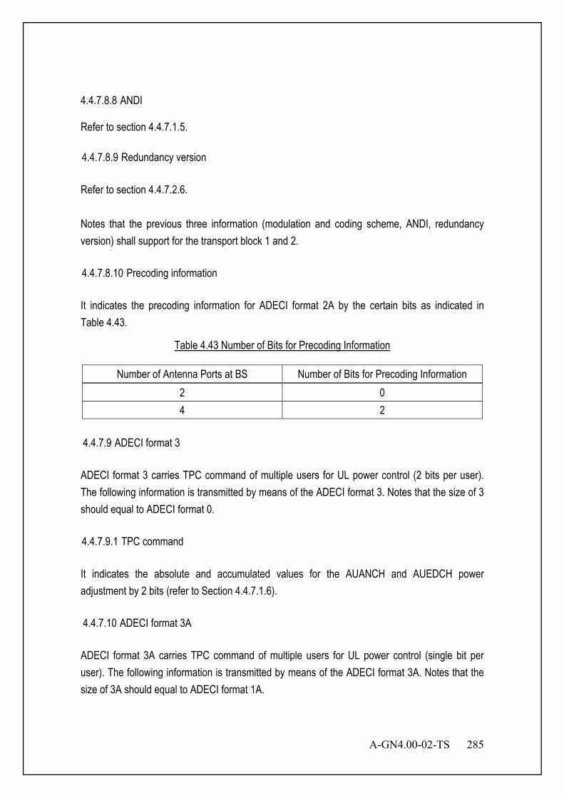
A-GN4.00-02-TS 285
4.4.7.8.8 ANDI Refer to section 4.4.7.1.5. 4.4.7.8.9 Redundancy version Refer to section 4.4.7.2.6. Notes that the previous three information (modulation and coding scheme, ANDI, redundancy version) shall support for the transport block 1 and 2. 4.4.7.8.10 Precoding information It indicates the precoding information for ADECI format 2A by the certain bits as indicated in Table 4.43.
Table 4.43 Number of Bits for Precoding Information
Number of Antenna Ports at BS Number of Bits for Precoding Information 2 0 4 2
4.4.7.9 ADECI format 3 ADECI format 3 carries TPC command of multiple users for UL power control (2 bits per user). The following information is transmitted by means of the ADECI format 3. Notes that the size of 3 should equal to ADECI format 0. 4.4.7.9.1 TPC command It indicates the absolute and accumulated values for the AUANCH and AUEDCH power adjustment by 2 bits (refer to Section 4.4.7.1.6). 4.4.7.10 ADECI format 3A ADECI format 3A carries TPC command of multiple users for UL power control (single bit per user). The following information is transmitted by means of the ADECI format 3A. Notes that the size of 3A should equal to ADECI format 1A.
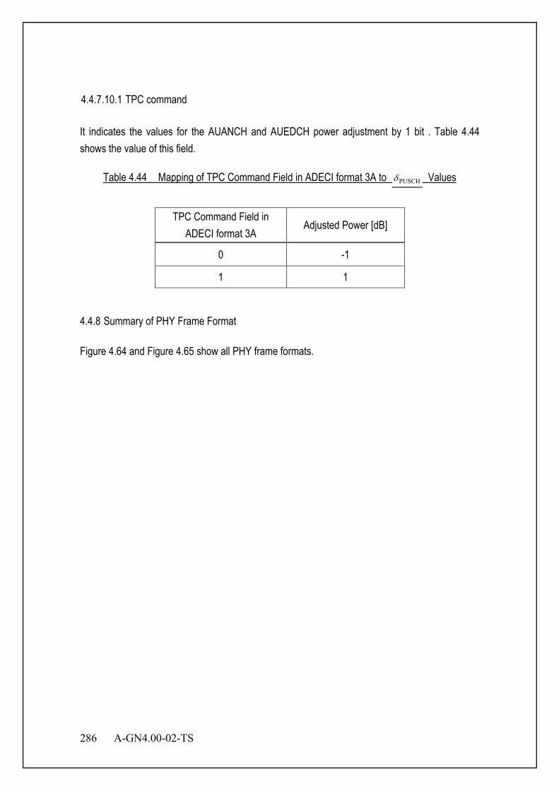
286 A-GN4.00-02-TS
4.4.7.10.1 TPC command It indicates the values for the AUANCH and AUEDCH power adjustment by 1 bit . Table 4.44 shows the value of this field.
Table 4.44 Mapping of TPC Command Field in ADECI format 3A to PUSCHδ Values
TPC Command Field in ADECI format 3A
Adjusted Power [dB]
0 -1
1 1 4.4.8 Summary of PHY Frame Format Figure 4.64 and Figure 4.65 show all PHY frame formats.
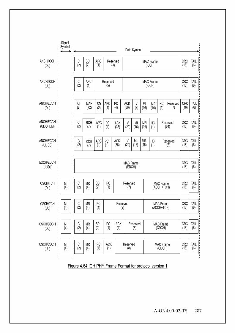
A-GN4.00-02-TS 287
Data Symbol
SD (2)
APC (1)
MAC Frame (ICCH)
Reserved (3)
CI (2)
CRC (16)
TAIL (6)
ANCH/ICCH (DL)
APC (1)
MAC Frame (ICCH)
Reserved (5)
CI (2)
CRC (16)
TAIL (6)
ANCH/ICCH (UL)
ANCH/ECCH (DL)
ANCH/ECCH (UL OFDM)
ANCH/ECCH (UL SC)
MAC Frame (EDCH)
CRC (16)
TAIL (6)
EXCH/EDCH (UL/DL)
SD (2)
PC (1)
MI (4)
MR (4)
MAC Frame (ACCH+TCH)
Reserved (7)
CI (2)
CRC (16)
TAIL (6)
CSCH/TCH (DL)
PC (1)
MI (4)
MR (4)
MAC Frame (ACCH+TCH)
Reserved (9)
CI (2)
CRC (16)
TAIL (6)
CSCH/TCH (UL)
SD (2)
PC (1)
ACK (1)
MI (4)
MR (4)
MAC Frame (CDCH)
Reserved (6)
CI (2)
CRC (16)
TAIL (6)
CSCH/CDCH (DL)
CRC (16)
TAIL (6)
PC (1)
ACK (1)
MI (4)
MR (4)
MAC Frame (CDCH)
Reserved (8)
CI (2)
CSCH/CDCH (UL)
Signal Symbol
MAP (72)
SD (2)
PC (4)
ACK (36)
V (7)
MI (16)
MR (16)
HC (1)
Reserved (7)
CI (2)
CRC (16)
TAIL (6)
APC (1)
RCH (7)
PC (1)
ACK (36)
V (20)
MI (16)
Reserved (64)
HC (1)
MR (16)
CI (2)
CRC (16)
TAIL (6)
APC (1)
RCH (7)
PC (1)
ACK (36)
V (20)
MI (16)
Reserved (6)
HC (1)
MR (16)
CI (2)
CRC (16)
TAIL (6)
APC (1)
Figure 4.64 ICH PHY Frame Format for protocol version 1
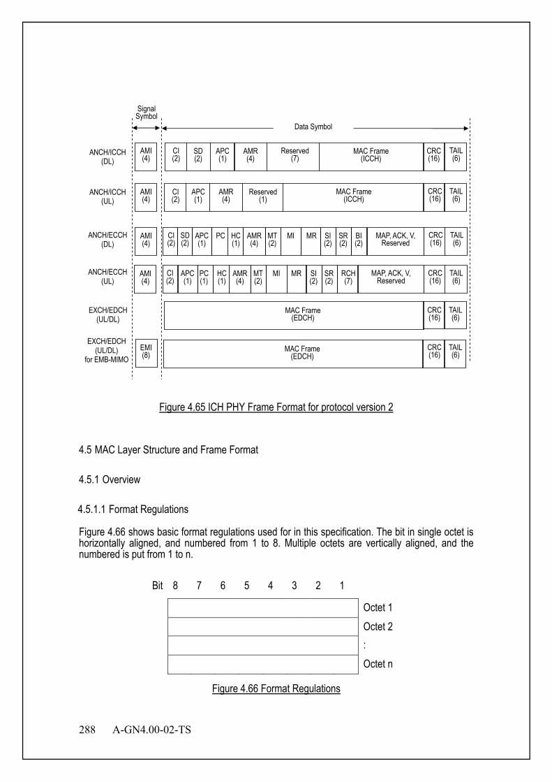
288 A-GN4.00-02-TS
AMI (4)
AMI (4)
AMI (4)
AMI (4)
Reserved (7)
AMR (4)
MAC Frame (ICCH)
MAC Frame (ICCH)
Reserved (1)
AMR (4)
APC (1)
PC
HC (1)
AMR (4)
MT (2)
MI
MR
SD (2)
CI (2)
CI (2)
APC (1)
CI (2)
SD (2)
APC (1)
SI (2)
SR (2)
BI (2)
APC (1)
PC (1)
HC (1)
AMR (4)
MT (2)
MI
MR
CI (2)
SI (2)
SR (2)
RCH (7)
MAP, ACK, V, Reserved
CRC (16)
TAIL (6)
MAC Frame (EDCH)
CRC (16)
TAIL (6)
EMI (8)
EXCH/EDCH (UL/DL)
EXCH/EDCH (UL/DL)
for EMB-MIMO
ANCH/ECCH (UL)
ANCH/ICCH (DL)
ANCH/ICCH (UL)
ANCH/ECCH (DL)
CRC (16)
MAP, ACK, V, Reserved
MAC Frame (EDCH)
CRC (16)
TAIL (6)
Data Symbol
Signal Symbol
TAIL (6)
CRC (16)
TAIL (6)
CRC (16)
TAIL (6)
Figure 4.65 ICH PHY Frame Format for protocol version 2
4.5 MAC Layer Structure and Frame Format 4.5.1 Overview 4.5.1.1 Format Regulations Figure 4.66 shows basic format regulations used for in this specification. The bit in single octet is horizontally aligned, and numbered from 1 to 8. Multiple octets are vertically aligned, and the numbered is put from 1 to n.
Bit 8 7 6 5 4 3 2 1
Octet 1 Octet 2 : Octet n
Figure 4.66 Format Regulations
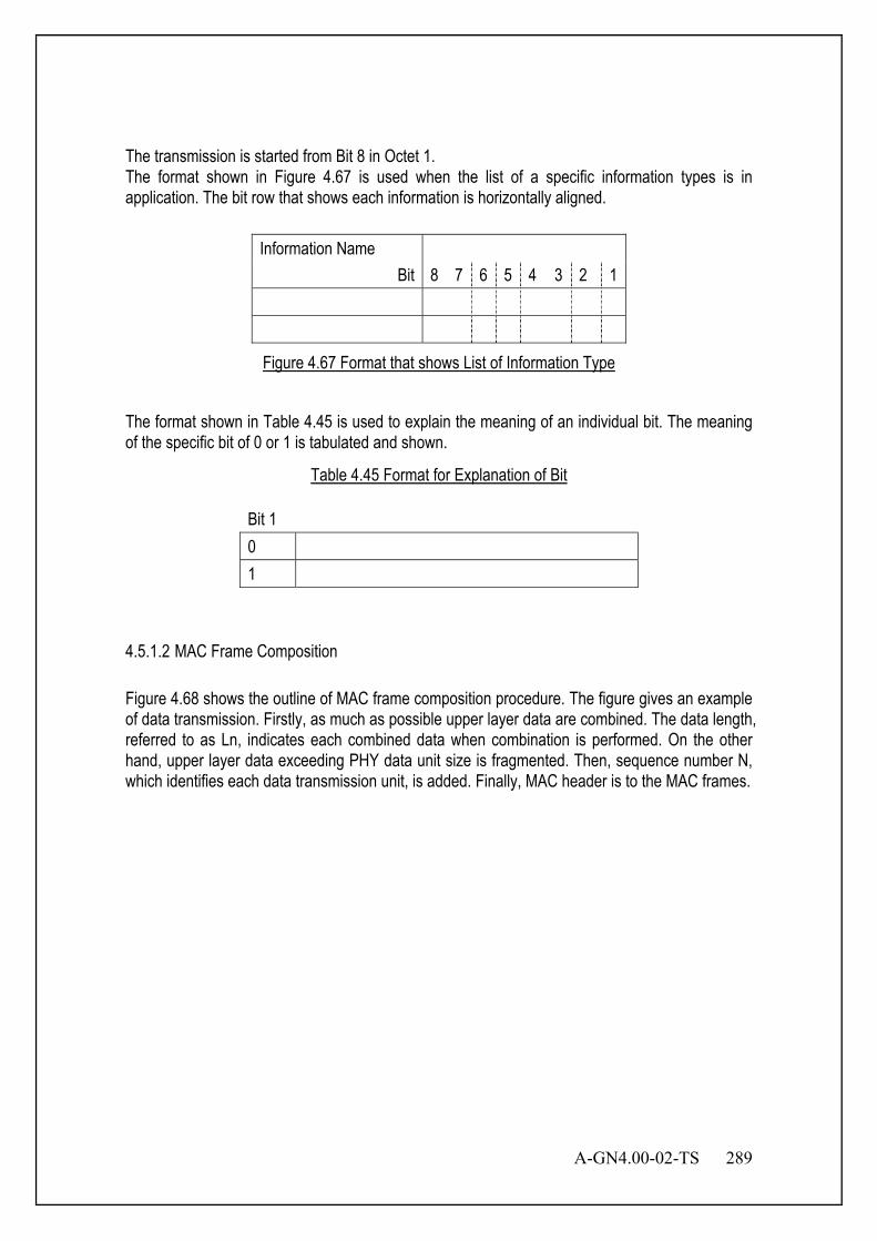
A-GN4.00-02-TS 289
The transmission is started from Bit 8 in Octet 1. The format shown in Figure 4.67 is used when the list of a specific information types is in application. The bit row that shows each information is horizontally aligned.
Information Name Bit 8 7 6 5 4 3 2 1
Figure 4.67 Format that shows List of Information Type
The format shown in Table 4.45 is used to explain the meaning of an individual bit. The meaning of the specific bit of 0 or 1 is tabulated and shown.
Table 4.45 Format for Explanation of Bit
Bit 1 0 1
4.5.1.2 MAC Frame Composition Figure 4.68 shows the outline of MAC frame composition procedure. The figure gives an example of data transmission. Firstly, as much as possible upper layer data are combined. The data length, referred to as Ln, indicates each combined data when combination is performed. On the other hand, upper layer data exceeding PHY data unit size is fragmented. Then, sequence number N, which identifies each data transmission unit, is added. Finally, MAC header is to the MAC frames.
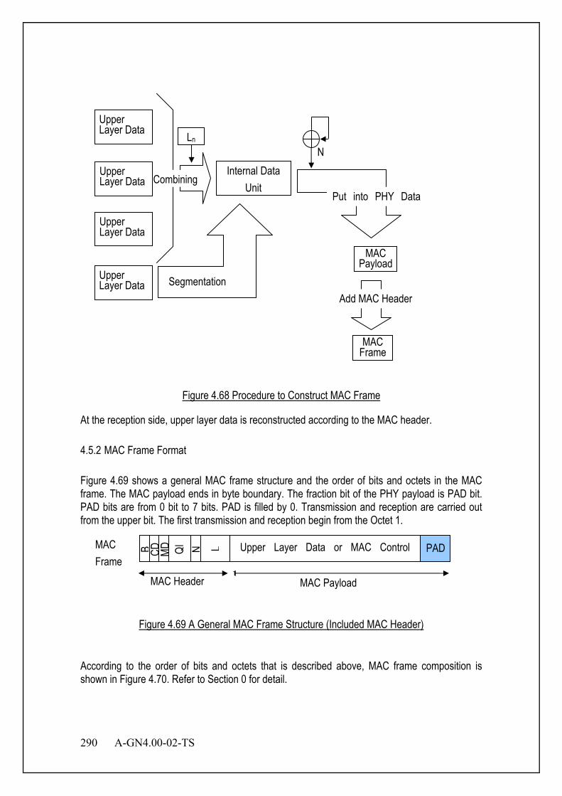
290 A-GN4.00-02-TS
Figure 4.68 Procedure to Construct MAC Frame
At the reception side, upper layer data is reconstructed according to the MAC header. 4.5.2 MAC Frame Format Figure 4.69 shows a general MAC frame structure and the order of bits and octets in the MAC frame. The MAC payload ends in byte boundary. The fraction bit of the PHY payload is PAD bit. PAD bits are from 0 bit to 7 bits. PAD is filled by 0. Transmission and reception are carried out from the upper bit. The first transmission and reception begin from the Octet 1.
Figure 4.69 A General MAC Frame Structure (Included MAC Header)
According to the order of bits and octets that is described above, MAC frame composition is shown in Figure 4.70. Refer to Section 0 for detail.
Upper Layer Data
Upper Layer Data
Upper Layer Data
Ln
Internal Data Unit
N
MAC Payload
MAC Frame
Add MAC Header
Upper Layer Data Segmentation
Put into PHY Data Combining
MAC Frame
B CD
MD
PAD N L Upper Layer Data or MAC Control
MAC Payload MAC Header
QI
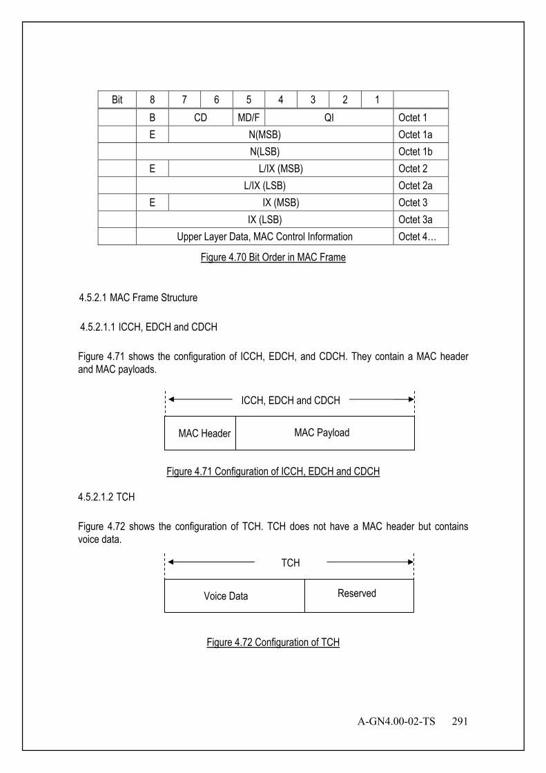
A-GN4.00-02-TS 291
Bit 8 7 6 5 4 3 2 1 B CD MD/F QI Octet 1 E N(MSB) Octet 1a N(LSB) Octet 1b E L/IX (MSB) Octet 2 L/IX (LSB) Octet 2a E IX (MSB) Octet 3 IX (LSB) Octet 3a Upper Layer Data, MAC Control Information Octet 4…
Figure 4.70 Bit Order in MAC Frame
4.5.2.1 MAC Frame Structure 4.5.2.1.1 ICCH, EDCH and CDCH Figure 4.71 shows the configuration of ICCH, EDCH, and CDCH. They contain a MAC header and MAC payloads.
Figure 4.71 Configuration of ICCH, EDCH and CDCH
4.5.2.1.2 TCH Figure 4.72 shows the configuration of TCH. TCH does not have a MAC header but contains voice data.
Figure 4.72 Configuration of TCH
Voice Data Reserved
TCH
MAC Header MAC Payload
ICCH, EDCH and CDCH
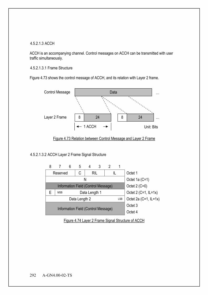
292 A-GN4.00-02-TS
4.5.2.1.3 ACCH ACCH is an accompanying channel. Control messages on ACCH can be transmitted with user traffic simultaneously. 4.5.2.1.3.1 Frame Structure Figure 4.73 shows the control message of ACCH, and its relation with Layer 2 frame.
Figure 4.73 Relation between Control Message and Layer 2 Frame
4.5.2.1.3.2 ACCH Layer 2 Frame Signal Structure
8 7 6 5 4 3 2 1 Reserved C RIL IL Octet 1
N Octet 1a (C=1) Information Field (Control Message) Octet 2 (C=0)
E MSB Data Length 1 Octet 2 (C=1, IL=1x) Data Length 2 LSB Octet 2a (C=1, IL=1x)
Information Field (Control Message) Octet 3 Octet 4
Figure 4.74 Layer 2 Frame Signal Structure of ACCH
Data Control Message …
Layer 2 Frame 8 24 8 24 …
Unit: Bits 1 ACCH

A-GN4.00-02-TS 293
Information Link Bit (IL)
Bit
Description 2 1 0 0 Middle Frame 0 1 End Frame 1 0 Leading Frame 1 1 Undivided Frame
Remaining Information Length Indication Bit (RIL)
Bit
Description 4 3 0 0 Control Message length is no octet.(No message) 0 1 Control Message length is one octet. 1 0 Control Message length is two octets. 1 1 Control Message length is three octets.
Control Message Bit (C)
Bit Description
0 It indicates that the MAC payload is unnumbered control information.
1 It indicates that the MAC payload is numbered control information.
Sequence Number (N)
When C=1, Sequence Number (N) is appended as Octet 1a. Following figure shows information element N.
Bit 8 7 6 5 4 3 2 1
N Octet 1a
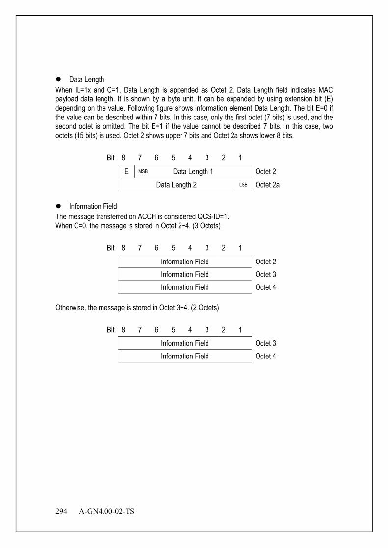
294 A-GN4.00-02-TS
Data Length
When IL=1x and C=1, Data Length is appended as Octet 2. Data Length field indicates MAC payload data length. It is shown by a byte unit. It can be expanded by using extension bit (E) depending on the value. Following figure shows information element Data Length. The bit E=0 if the value can be described within 7 bits. In this case, only the first octet (7 bits) is used, and the second octet is omitted. The bit E=1 if the value cannot be described 7 bits. In this case, two octets (15 bits) is used. Octet 2 shows upper 7 bits and Octet 2a shows lower 8 bits.
Bit 8 7 6 5 4 3 2 1
E MSB Data Length 1 Octet 2 Data Length 2 LSB Octet 2a
Information Field
The message transferred on ACCH is considered QCS-ID=1. When C=0, the message is stored in Octet 2~4. (3 Octets)
Bit 8 7 6 5 4 3 2 1
Information Field Octet 2 Information Field Octet 3 Information Field Octet 4
Otherwise, the message is stored in Octet 3~4. (2 Octets)
Bit 8 7 6 5 4 3 2 1
Information Field Octet 3 Information Field Octet 4
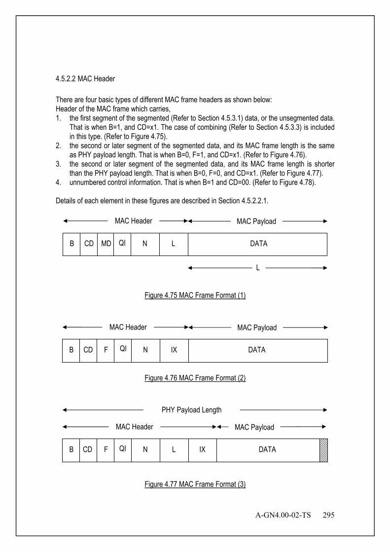
A-GN4.00-02-TS 295
4.5.2.2 MAC Header There are four basic types of different MAC frame headers as shown below: Header of the MAC frame which carries, 1. the first segment of the segmented (Refer to Section 4.5.3.1) data, or the unsegmented data.
That is when B=1, and CD=x1. The case of combining (Refer to Section 4.5.3.3) is included in this type. (Refer to Figure 4.75).
2. the second or later segment of the segmented data, and its MAC frame length is the same as PHY payload length. That is when B=0, F=1, and CD=x1. (Refer to Figure 4.76).
3. the second or later segment of the segmented data, and its MAC frame length is shorter than the PHY payload length. That is when B=0, F=0, and CD=x1. (Refer to Figure 4.77).
4. unnumbered control information. That is when B=1 and CD=00. (Refer to Figure 4.78). Details of each element in these figures are described in Section 4.5.2.2.1.
Figure 4.75 MAC Frame Format (1)
Figure 4.76 MAC Frame Format (2)
Figure 4.77 MAC Frame Format (3)
B F N L DATA
MAC Header MAC Payload
PHY Payload Length
IX CD QI
B CD F N IX DATA
MAC Header MAC Payload
QI
MAC Header MAC Payload
L
MD CD B QI N L DATA
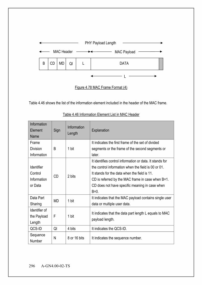
296 A-GN4.00-02-TS
Figure 4.78 MAC Frame Format (4)
Table 4.46 shows the list of the information element included in the header of the MAC frame.
Table 4.46 Information Element List in MAC Header
Information Element Name
Sign Information Length
Explanation
Frame Division Information
B 1 bit It indicates the first frame of the set of divided segments or the frame of the second segments or later.
Identifier Control Information or Data
CD 2 bits
It identifies control information or data. It stands for the control information when the field is 00 or 01. It stands for the data when the field is 11. CD is referred by the MAC frame in case when B=1. CD does not have specific meaning in case when B=0.
Data Part Sharing
MD 1 bit It indicates that the MAC payload contains single user data or multiple user data.
Identifier of the Payload Length
F 1 bit It indicates that the data part length L equals to MAC payload length.
QCS-ID QI 4 bits It indicates the QCS-ID. Sequence Number
N 8 or 16 bits It indicates the sequence number.
B CD MD L DATA
MAC Header MAC Payload
PHY Payload Length
QI
L

A-GN4.00-02-TS 297
Information Element Name
Sign Information Length
Explanation
Index IX 8 or 16 bits
It indicates the number of bytes of upper layer data that has already been sent in the earlier MAC frames. Basically, it indicates the location of the upper layer data that the MAC payload is filled up.
Data Part Length
L 8 or 16 bits
It indicates data length contained in the MAC payload in case when MD=0. It indicates the total number of data lengths contained in the MAC payload in case when MD=1.
Data Length of User
Ln 8 or 16 bits It indicates each length of multiple user data when MD=1.
Information Area
DATA Upper layer data is included in the MAC payload.
4.5.2.2.1 Each Field of MAC Header 4.5.2.2.1.1 Frame Division Information (B) B field shows the first frame in data transmission by dividing upper layer data into two or more MAC frames. It is used to restructure the divided transmission data.
Table 4.47 Frame Division Information
Bit 1 0 The second frame or later when the upper
layer data is divided. 1 The first frame when the upper layer data is
divided or undivided frame
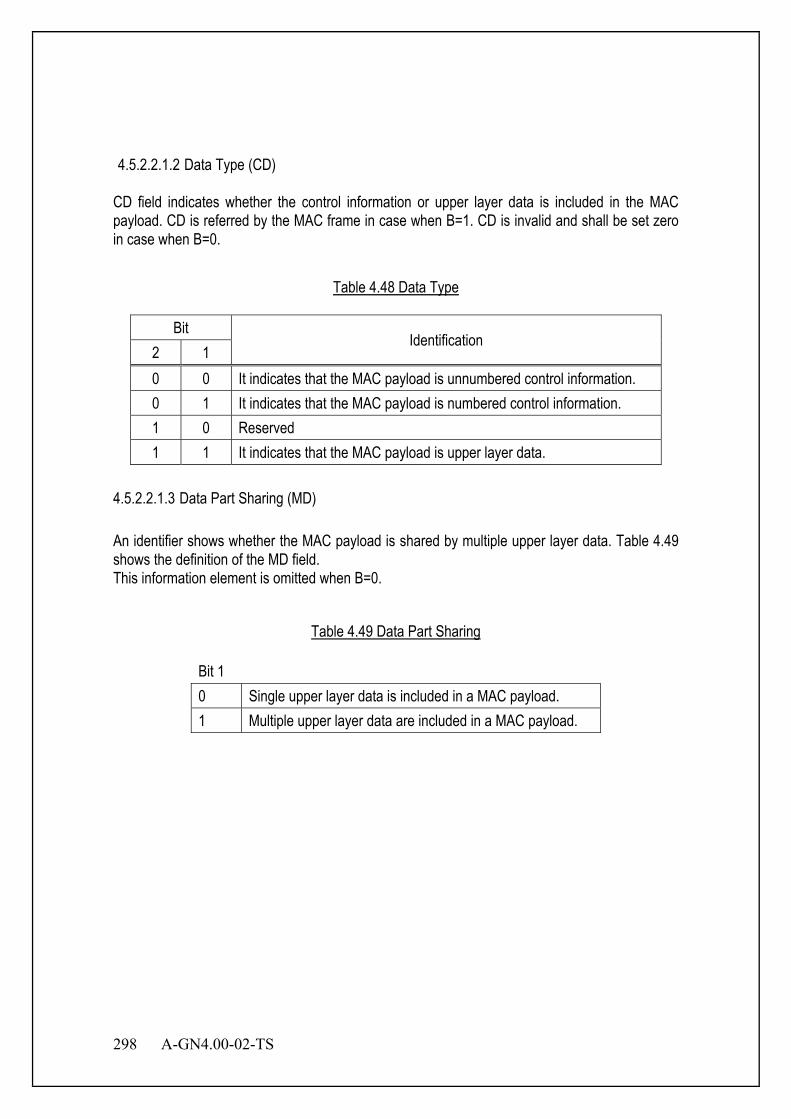
298 A-GN4.00-02-TS
4.5.2.2.1.2 Data Type (CD)
CD field indicates whether the control information or upper layer data is included in the MAC payload. CD is referred by the MAC frame in case when B=1. CD is invalid and shall be set zero in case when B=0.
Table 4.48 Data Type
Bit Identification
2 1 0 0 It indicates that the MAC payload is unnumbered control information. 0 1 It indicates that the MAC payload is numbered control information. 1 0 Reserved 1 1 It indicates that the MAC payload is upper layer data.
4.5.2.2.1.3 Data Part Sharing (MD) An identifier shows whether the MAC payload is shared by multiple upper layer data. Table 4.49 shows the definition of the MD field. This information element is omitted when B=0.
Table 4.49 Data Part Sharing
Bit 1 0 Single upper layer data is included in a MAC payload. 1 Multiple upper layer data are included in a MAC payload.

A-GN4.00-02-TS 299
4.5.2.2.1.4 Bit of Payload Length Identification (F) An identifier indicates whether the MAC payload length is specified by L field or not, because the MAC frame length is the same as the PHY payload length. The bit definition of F field is as shown in Table 4.50. This information element is omitted when B=1.
Table 4.50 Bit of Payload Surplus Judgment
Bit 1 0 The MAC payload is specified by L field. 1 Because PHY payload length is the same as
the MAC frame length, the length of the MAC payload is not specified by L field.
4.5.2.2.1.5 QCS-ID (QI) This number identifies the quality service sessions. QCS-ID is assigned for every session and managed between MS and BS. The length of this field is 4 bits. When control information which does not distinguish QCS is used, this value is set to 0 (QCS-ID=1). Otherwise it is set to any of the number from 1 to 15 to specify each QCS. 4.5.2.2.1.6 Sequence Number (N) This is a series of continuous numbers to identify the data. N is supervised for each user and incremented by upper layer data unit or PHY data unit (CRC unit) for each QCS. The area of index can be expanded by using extension bit (E) depending on the value. The bit E=0 if the value can be described within 7 bits. In this case, only the first octet (7 bits) is used, and the second octet is omitted. The bit E=1 if the value cannot be described within 7 bits. In this case, two octets (15 bits) is used. Octet 1a shows upper 7 bits and Octet 1b shows lower 8 bits.
Increment Timing 1. In case of combining (Refer to Section 4.5.3.3), N is incremented by PHY data unit. 2. In case of segmentation (Refer to Section 0), N is incremented by upper layer data unit. 3. In case of concatenation (Refer to Section 4.5.3.4), N is incremented by upper layer
data unit. 4. In other cases than combining segmentation or concatenation, N is incremented by
PHY data unit (= upper layer data unit).
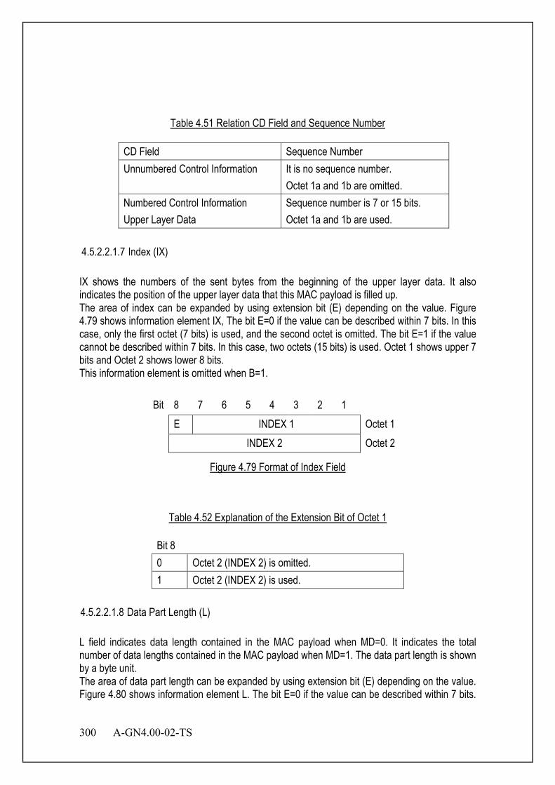
300 A-GN4.00-02-TS
Table 4.51 Relation CD Field and Sequence Number
CD Field Sequence Number Unnumbered Control Information It is no sequence number.
Octet 1a and 1b are omitted. Numbered Control Information Upper Layer Data
Sequence number is 7 or 15 bits. Octet 1a and 1b are used.
4.5.2.2.1.7 Index (IX) IX shows the numbers of the sent bytes from the beginning of the upper layer data. It also indicates the position of the upper layer data that this MAC payload is filled up. The area of index can be expanded by using extension bit (E) depending on the value. Figure 4.79 shows information element IX, The bit E=0 if the value can be described within 7 bits. In this case, only the first octet (7 bits) is used, and the second octet is omitted. The bit E=1 if the value cannot be described within 7 bits. In this case, two octets (15 bits) is used. Octet 1 shows upper 7 bits and Octet 2 shows lower 8 bits. This information element is omitted when B=1.
Bit 8 7 6 5 4 3 2 1 E INDEX 1 Octet 1 INDEX 2 Octet 2
Figure 4.79 Format of Index Field
Table 4.52 Explanation of the Extension Bit of Octet 1
Bit 8 0 Octet 2 (INDEX 2) is omitted. 1 Octet 2 (INDEX 2) is used.
4.5.2.2.1.8 Data Part Length (L) L field indicates data length contained in the MAC payload when MD=0. It indicates the total number of data lengths contained in the MAC payload when MD=1. The data part length is shown by a byte unit. The area of data part length can be expanded by using extension bit (E) depending on the value. Figure 4.80 shows information element L. The bit E=0 if the value can be described within 7 bits.

A-GN4.00-02-TS 301
In this case, only the first octet (7 bits) is used, and the second octet is omitted. The bit E=1 if the value cannot be described 7 bits. In this case, two octets (15 bits) is used. Octet 1 shows upper 7 bits and Octet 2 shows lower 8 bits. This information element is omitted when F=1.
Bit 8 7 6 5 4 3 2 1
E Data Length 1 Octet 1 Data Length 2 Octet 2
Figure 4.80 Data Part Length / User Data Length
Table 4.53 Explanation of the Extension Bit of Octet 1
Bit 8 0 Octet 2 (data length 2) is omitted. 1 Octet 2 (data length 2) is used.
4.5.2.2.1.9 User Data Length (Ln) When one MAC payload includes upper layer data for multiple upper layer data, this information element shows each upper layer data length. The format of the element uses the same data part length. Refer to Figure 4.80 and Table 4.53. This information element is omitted when MD=0. 4.5.2.2.1.10 Information Area (DATA) This is the dedicated data area for the MAC frame. It includes upper layer data, MAC control protocol and access establishment phase control protocol information. 4.5.2.3 MAC Payload There are two types of MAC payload as shown below:
Upper Layer Data MAC Control Information
4.5.2.3.1 Upper Layer Data When CD field in MAC header is upper layer data, upper layer data is included in MAC payload.
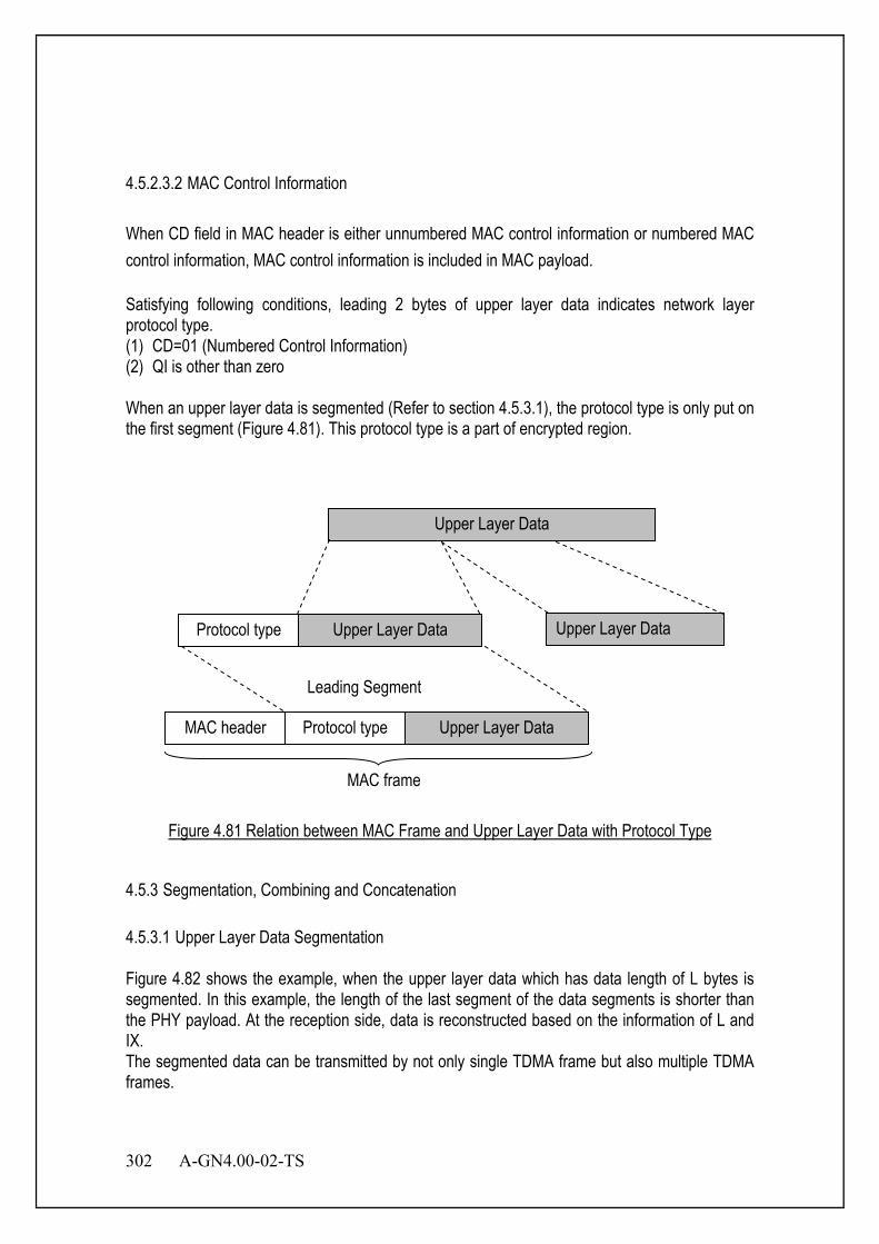
302 A-GN4.00-02-TS
4.5.2.3.2 MAC Control Information When CD field in MAC header is either unnumbered MAC control information or numbered MAC control information, MAC control information is included in MAC payload. Satisfying following conditions, leading 2 bytes of upper layer data indicates network layer protocol type. (1) CD=01 (Numbered Control Information) (2) QI is other than zero When an upper layer data is segmented (Refer to section 4.5.3.1), the protocol type is only put on the first segment (Figure 4.81). This protocol type is a part of encrypted region.
Figure 4.81 Relation between MAC Frame and Upper Layer Data with Protocol Type
4.5.3 Segmentation, Combining and Concatenation 4.5.3.1 Upper Layer Data Segmentation Figure 4.82 shows the example, when the upper layer data which has data length of L bytes is segmented. In this example, the length of the last segment of the data segments is shorter than the PHY payload. At the reception side, data is reconstructed based on the information of L and IX. The segmented data can be transmitted by not only single TDMA frame but also multiple TDMA frames.
Upper Layer Data
Protocol type Upper Layer Data Upper Layer Data
Protocol type Upper Layer Data MAC header
MAC frame
Leading Segment
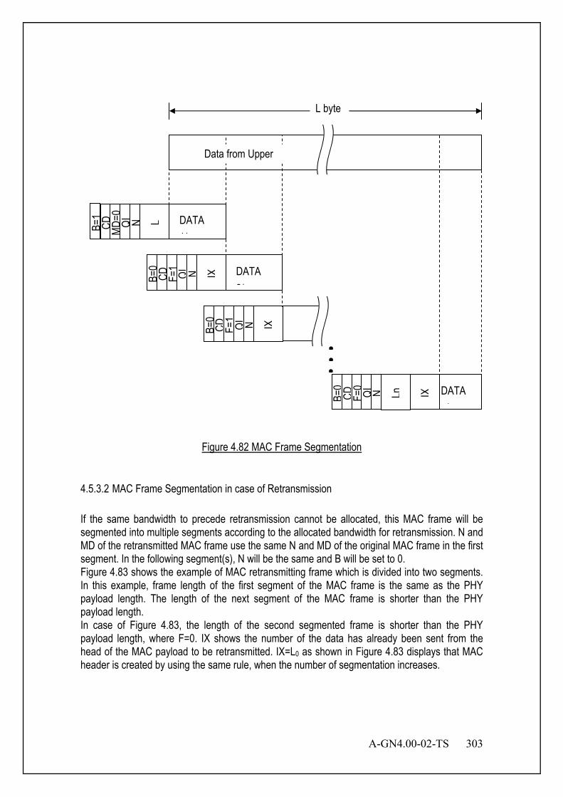
A-GN4.00-02-TS 303
Figure 4.82 MAC Frame Segmentation
4.5.3.2 MAC Frame Segmentation in case of Retransmission If the same bandwidth to precede retransmission cannot be allocated, this MAC frame will be segmented into multiple segments according to the allocated bandwidth for retransmission. N and MD of the retransmitted MAC frame use the same N and MD of the original MAC frame in the first segment. In the following segment(s), N will be the same and B will be set to 0. Figure 4.83 shows the example of MAC retransmitting frame which is divided into two segments. In this example, frame length of the first segment of the MAC frame is the same as the PHY payload length. The length of the next segment of the MAC frame is shorter than the PHY payload length. In case of Figure 4.83, the length of the second segmented frame is shorter than the PHY payload length, where F=0. IX shows the number of the data has already been sent from the head of the MAC payload to be retransmitted. IX=L0 as shown in Figure 4.83 displays that MAC header is created by using the same rule, when the number of segmentation increases.
B=1
CD
MD=0
N L DATA 1/
B=0
CD
F=1 N IX DATA
2/
B=0
CD
F=1 N IX
B=0
CD
F=0 N IX DATA
/ Ln
Data from Upper
••
•
L byte QI
QI
QI
QI
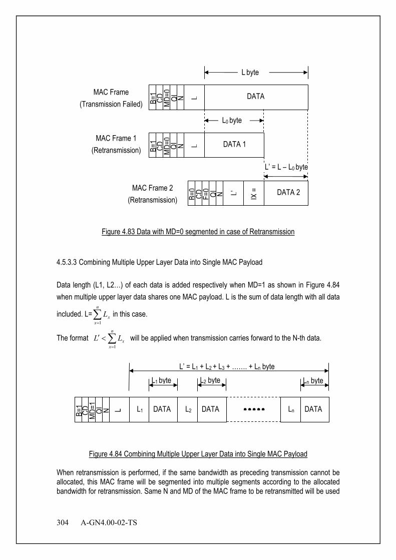
304 A-GN4.00-02-TS
Figure 4.83 Data with MD=0 segmented in case of Retransmission
4.5.3.3 Combining Multiple Upper Layer Data into Single MAC Payload Data length (L1, L2…) of each data is added respectively when MD=1 as shown in Figure 4.84 when multiple upper layer data shares one MAC payload. L is the sum of data length with all data
included. L=∑=
n
xxL
1in this case.
The format ∑=
<′n
xxLL
1 will be applied when transmission carries forward to the N-th data.
Figure 4.84 Combining Multiple Upper Layer Data into Single MAC Payload
When retransmission is performed, if the same bandwidth as preceding transmission cannot be allocated, this MAC frame will be segmented into multiple segments according to the allocated bandwidth for retransmission. Same N and MD of the MAC frame to be retransmitted will be used
CD
MD=1
N L L1 DATA L2 DATA Ln DATA •••••
L1 byte L2 byte Ln byte
L’ = L1 + L2 + L3 + ……. + Ln byte
QI
B=1
B=1
CD
MD=0
N L DATA MAC Frame
(Transmission Failed)
B=1
CD
MD=0
N L DATA 1
B=0
CD
F=0 N IX =
DATA 2
L0 byte
L byte
MAC Frame 1 (Retransmission)
MAC Frame 2 (Retransmission)
QI
QI
QI L’
L’ = L – L0 byte

A-GN4.00-02-TS 305
in the first segment. And N will be the same in the following segment and B will be 0. Figure 4.85 shows the example of retransmitting MAC frame containing multiple upper layer data divided into two segments. In this example, frame length of the first segment of the MAC frame is the same as the PHY payload length. Length of the second segment of the MAC frame is shorter than the PHY payload length. In case of Figure 4.85, length of the second segmented frame is defined to be shorter than the PHY payload length. Hence, F=0. IX shows the number of data sent from the head of the MAC payload to be retransmitted. IX=L’ as shown in Figure 4.85. MAC header is created using the same rule when the number of segmentation increases. This feature is negotiated in information element Communication Parameter and MS Performance.
Figure 4.85 Data with MD=1 segmented in case of Retransmission
4.5.3.4 MAC Frame Concatenation MAC frame concatenation is permitted with the following conditions. MAC frame concatenation here stands for multiple MAC frame to be included in a PHY data unit. Subsequent 24bits of last concatenated MAC frame are set to all 0. Satisfying following conditions, further MAC frame can be concatenated.
• PHY Payload Length – Current total MAC Frame Length ≥ 4 bytes • Twenty-four leading bits of trailing MAC frame is not all zero.
Figure 4.86 shows an example when MAC frames are concatenated in a PHY payload. In the
MAC Frame (Transmission Failed)
B=1
CD
MD=1
N L
B=0
CD
F=0 N IX
=L’
DATA
L’’
L’’ = L – L’ b t
L’ = L1 + L2‘ byte
L = L1 + L2 + L3
Segmented MAC Frame 2 (Retransmission)
B=1
CD
MD=1
N L L1 DATA L2 DATA L3 DATA
L1 DATA L2 DATA
L3 DATA
QI
QI
QI
Segmented MAC Frame 1
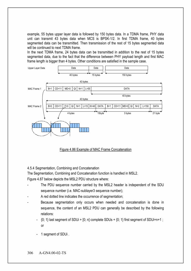
306 A-GN4.00-02-TS
example, 55 bytes upper layer data is followed by 150 bytes data. In a TDMA frame, PHY data unit can transmit 43 bytes data when MCS is BPSK-1/2. In first TDMA frame, 40 bytes segmented data can be transmitted. Then transmission of the rest of 15 bytes segmented data will be continued to next TDMA frame. In the next TDMA frame, 24 bytes data can be transmitted in addition to the rest of 15 bytes segmented data, due to the fact that the difference between PHY payload length and first MAC frame length is bigger than 4 bytes. Other conditions are satisfied in the sample case. Upper Layer Data
MAC Frame 1
MAC Frame 2
43 bytes
4 bytes 3 bytes 15byte
QI N=1 L=15 IX=40B=0 CD=11
21 byte
DATA
Data
MD=0 QI N=2 L=150 DATA B=1 CD=11F=0
40 bytes 150 bytes
43 bytes
DATA
40 bytes
15 bytes
B=1 CD=11 MD=0
Data
QI N=1 L=55
Data
Figure 4.86 Example of MAC Frame Concatenation
4.5.4 Segmentation, Combining and Concatenation The Segmentation, Combining and Concatenation function is handled in MSL2. Figure 4.87 below depicts the MSL2 PDU structure where: - The PDU sequence number carried by the MSL2 header is independent of the SDU
sequence number (i.e. MAC-sublayer3 sequence number); - A red dotted line indicates the occurrence of segmentation; - Because segmentation only occurs when needed and concatenation is done in
sequence, the content of an MSL2 PDU can generally be described by the following relations:
- {0; 1} last segment of SDUi + [0; n] complete SDUs + {0; 1} first segment of SDUi+n+1 ; or
- 1 segment of SDUi .
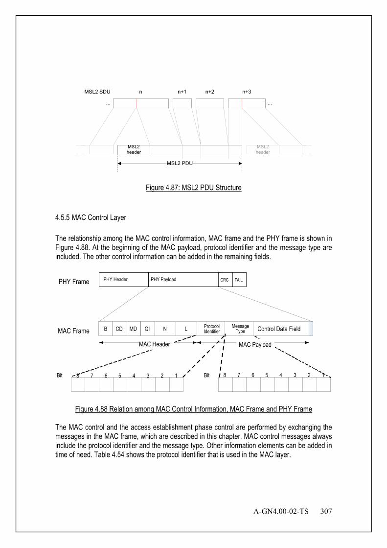
A-GN4.00-02-TS 307
MSL2header
MSL2 PDU
......
n n+1 n+2 n+3MSL2 SDU
MSL2 header
Figure 4.87: MSL2 PDU Structure
4.5.5 MAC Control Layer The relationship among the MAC control information, MAC frame and the PHY frame is shown in Figure 4.88. At the beginning of the MAC payload, protocol identifier and the message type are included. The other control information can be added in the remaining fields.
Figure 4.88 Relation among MAC Control Information, MAC Frame and PHY Frame
The MAC control and the access establishment phase control are performed by exchanging the messages in the MAC frame, which are described in this chapter. MAC control messages always include the protocol identifier and the message type. Other information elements can be added in time of need. Table 4.54 shows the protocol identifier that is used in the MAC layer.
PHY Frame PHY Payload CRC TAIL
12345678Bit Bit
MAC Frame
PHY Header
12345678
Control Data Field LMD B NCD
MAC Payload MAC Header
QI Protocol Identifier
Message Type
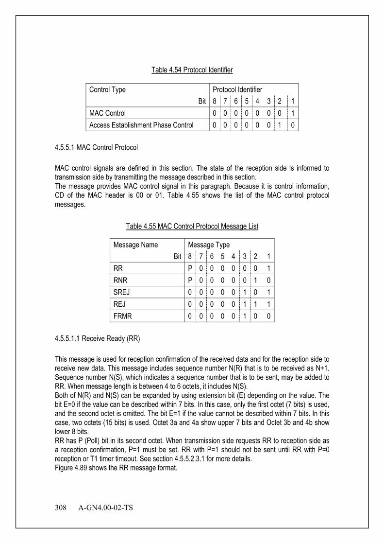
308 A-GN4.00-02-TS
Table 4.54 Protocol Identifier
Control Type Protocol Identifier Bit 8 7 6 5 4 3 2 1
MAC Control 0 0 0 0 0 0 0 1 Access Establishment Phase Control 0 0 0 0 0 0 1 0
4.5.5.1 MAC Control Protocol MAC control signals are defined in this section. The state of the reception side is informed to transmission side by transmitting the message described in this section. The message provides MAC control signal in this paragraph. Because it is control information, CD of the MAC header is 00 or 01. Table 4.55 shows the list of the MAC control protocol messages.
Table 4.55 MAC Control Protocol Message List
Message Name Message Type Bit 8 7 6 5 4 3 2 1
RR P 0 0 0 0 0 0 1 RNR P 0 0 0 0 0 1 0 SREJ 0 0 0 0 0 1 0 1 REJ 0 0 0 0 0 1 1 1 FRMR 0 0 0 0 0 1 0 0
4.5.5.1.1 Receive Ready (RR) This message is used for reception confirmation of the received data and for the reception side to receive new data. This message includes sequence number N(R) that is to be received as N+1. Sequence number N(S), which indicates a sequence number that is to be sent, may be added to RR. When message length is between 4 to 6 octets, it includes N(S). Both of N(R) and N(S) can be expanded by using extension bit (E) depending on the value. The bit E=0 if the value can be described within 7 bits. In this case, only the first octet (7 bits) is used, and the second octet is omitted. The bit E=1 if the value cannot be described within 7 bits. In this case, two octets (15 bits) is used. Octet 3a and 4a show upper 7 bits and Octet 3b and 4b show lower 8 bits. RR has P (Poll) bit in its second octet. When transmission side requests RR to reception side as a reception confirmation, P=1 must be set. RR with P=1 should not be sent until RR with P=0 reception or T1 timer timeout. See section 4.5.5.2.3.1 for more details. Figure 4.89 shows the RR message format.
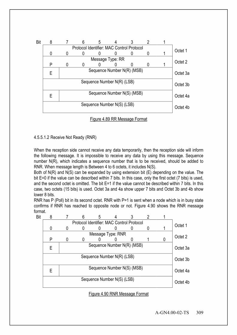
A-GN4.00-02-TS 309
Bit 8 7 6 5 4 3 2 1 Protocol Identifier: MAC Control Protocol Octet 1 0 0 0 0 0 0 0 1 Message Type: RR Octet 2 P 0 0 0 0 0 0 1 E Sequence Number N(R) (MSB) Octet 3a Sequence Number N(R) (LSB) Octet 3b E Sequence Number N(S) (MSB) Octet 4a Sequence Number N(S) (LSB) Octet 4b
Figure 4.89 RR Message Format
4.5.5.1.2 Receive Not Ready (RNR) When the reception side cannot receive any data temporarily, then the reception side will inform the following message. It is impossible to receive any data by using this message. Sequence number N(R), which indicates a sequence number that is to be received, should be added to RNR. When message length is Between 4 to 6 octets, it includes N(S). Both of N(R) and N(S) can be expanded by using extension bit (E) depending on the value. The bit E=0 if the value can be described within 7 bits. In this case, only the first octet (7 bits) is used, and the second octet is omitted. The bit E=1 if the value cannot be described within 7 bits. In this case, two octets (15 bits) is used. Octet 3a and 4a show upper 7 bits and Octet 3b and 4b show lower 8 bits. RNR has P (Poll) bit in its second octet. RNR with P=1 is sent when a node which is in busy state confirms if RNR has reached to opposite node or not. Figure 4.90 shows the RNR message format.
Bit 8 7 6 5 4 3 2 1 Protocol Identifier: MAC Control Protocol Octet 1 0 0 0 0 0 0 0 1 Message Type: RNR Octet 2 P 0 0 0 0 0 1 0 E Sequence Number N(R) (MSB) Octet 3a Sequence Number N(R) (LSB) Octet 3b E Sequence Number N(S) (MSB) Octet 4a Sequence Number N(S) (LSB) Octet 4b
Figure 4.90 RNR Message Format

310 A-GN4.00-02-TS
4.5.5.1.3 Frame Reject (FRMR) Reception side notifies that the received frame is rejected because the reception side cannot receive the expected data. Figure 4.91 shows the FRMR message. Table 4.56 shows the list of rejected reasons.
Bit 8 7 6 5 4 3 2 1 Protocol Identifier: MAC Control Protocol Octet 1 0 0 0 0 0 0 0 1 Message Type: FRMR Octet 2 0 0 0 0 0 1 0 0 Reject Reason Octet 3
Figure 4.91 FRMR Message Format
Table 4.56 Reject Reason List
Reject Reason Reject Reason Field Bit 8 7 6 5 4 3 2 1
Undefined Protocol Identifier 0 0 0 0 0 0 0 1 Undefined Message Type 0 0 0 0 0 0 1 0 Undefined CD Field 0 0 0 0 0 0 1 1 Incorrect Data Part Length(L) 0 0 0 0 0 1 0 0 Incorrect Index(IX) 0 0 0 0 0 1 0 1 Incorrect Sequence Number(N) 0 0 0 0 0 1 1 0 Over the limit of retransmission times 0 0 0 0 0 1 1 1 Other Error 1 1 1 1 1 1 1 1
4.5.5.1.4 Selective Reject (SREJ) SREJ message is sent when retransmission is requested to specify the sequence number. Figure 4.92 shows the SREJ message. N(R) can be expanded by using extension bit (E) depending on the value. The bit E=0 if the value can be described within 7 bits. In this case, only the first octet (7 bits) is used, and the second octet is omitted. The bit E=1 if the value cannot be described within 7 bits. In this case, two octets (15 bits) is used. Octet 3a shows upper 7 bits and Octet 3b shows lower 8 bits.
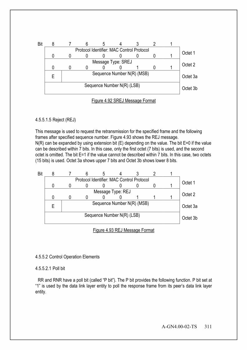
A-GN4.00-02-TS 311
Bit 8 7 6 5 4 3 2 1 Protocol Identifier: MAC Control Protocol Octet 1 0 0 0 0 0 0 0 1 Message Type: SREJ Octet 2 0 0 0 0 0 1 0 1 E Sequence Number N(R) (MSB) Octet 3a Sequence Number N(R) (LSB) Octet 3b
Figure 4.92 SREJ Message Format
4.5.5.1.5 Reject (REJ) This message is used to request the retransmission for the specified frame and the following frames after specified sequence number. Figure 4.93 shows the REJ message. N(R) can be expanded by using extension bit (E) depending on the value. The bit E=0 if the value can be described within 7 bits. In this case, only the first octet (7 bits) is used, and the second octet is omitted. The bit E=1 if the value cannot be described within 7 bits. In this case, two octets (15 bits) is used. Octet 3a shows upper 7 bits and Octet 3b shows lower 8 bits.
Bit 8 7 6 5 4 3 2 1 Protocol Identifier: MAC Control Protocol Octet 1 0 0 0 0 0 0 0 1 Message Type: REJ Octet 2 0 0 0 0 0 1 1 1 E Sequence Number N(R) (MSB) Octet 3a Sequence Number N(R) (LSB) Octet 3b
Figure 4.93 REJ Message Format
4.5.5.2 Control Operation Elements 4.5.5.2.1 Poll bit RR and RNR have a poll bit (called “P bit”). The P bit provides the following function. P bit set at “1” is used by the data link layer entity to poll the response frame from its peer’s data link layer entity.
312 A-GN4.00-02-TS
4.5.5.2.2 Variables 4.5.5.2.2.1 The range of a sequence number and variable The range of a sequence number and variable described in this section is from 0 to 32767. The value wraps around within this range. Because sequence number N field in MAC header length is 15 bits including expanded octet, a maximum sequence number is a modulo value of 32768. 4.5.5.2.2.2 Send state variable V(S) Data link layer entity has a send state variable V(S). V(S) indicates the sequence number that should be transmitted next. V(S) is increased by one for each numbered frame transmission. However, V(S) must not exceed the value of adding the maximum number of window size to V(A). 4.5.5.2.2.3 Acknowledge state variable V(A) Data link layer entity has an acknowledge state variable V(A). V(A) indicates the sequence number that should be acknowledged next by its peer. (V(A)-1 is equal to N(S) of the numbered frame acknowledged last.) The value of V(A) is updated by the correct N(R) value acknowledged by the RR/RNR frame transmitted from its peer. The correct N(R) value is in the range of V(A)≤N(R)≤V(S). 4.5.5.2.2.4 Send sequence number N(S)
Numbered frame have a send sequence number, N(S) indicates the sequence number of transmitted frame. N(S) is set to V(S) prior to transmission of numbered frame(s). 4.5.5.2.2.5 Receive state variable V(R) The data link layer entity has a receive state variable V(R). V(R) indicates the sequence number of the numbered frame that should be received next. V(R) is set at the newest sequence number added by 1 which can be continuously received by starting from current V(R). 4.5.5.2.2.6 Receive sequence number N(R)
RR/RNR frames have receive sequence numbers for data frames that should be received next. Prior to RR/RNR frame transmission, N(R) is set so that it becomes equal to the newest V(R). N(R) indicates the data link layer entity which sent such N(R) correctly received all data frames having numbers up to N(R)-1. 4.5.5.2.3 Timers 4.5.5.2.3.1 Response acknowledge timer T1 T1 timer starts when RR/RNR frame with P=1 was received, and stops when receiving its

A-GN4.00-02-TS 313
response frame or REJ/SREJ frame. When the data link layer entity detects T1 timer’s time-out retry out, it sends FRMR frame. 4.5.5.2.3.2 Response transfer timer T2 T2 timer is used to delay sending RR/RNR frame for receiving normal numbered frame. When T2 timer stopped and the data link layer entity receives numbered frame, it starts T2 timer. When T2 timer expires, the data link layer entity sends RR/RNR response frame with P=0. When T2 timer is active, although it receives numbered frame, T2 timer goes on. When it receives command frame with P=1, T2 timer is stopped. 4.5.5.2.3.3 Peer station busy supervisory timer T3 T3 is the timer to supervise the busy state of opposite side. When the data link layer entity receives RNR frame, T3 timer is started. When T3 timer expires, the data link layer entity send RR/RNR frame in order to check peer state. While T3 timer is in active, if the data link layer entity receives RNR frame then restarts T3 timer, if it receives RR frame then stops T3 timer. 4.5.5.2.3.4 Link alive check timer T4
Satisfying one or more following conditions, the data link layer entity starts T4 timer. - No data to send - Outstanding - My station is busy and outstanding - Receive RR/REJ/SREJ when the data link layer entity has no data to send Satisfying one or more following conditions, the data link layer entity stops T4 timer. - V(S) equals to N(R) in received RR frame - Receive newer numbered frame except for retransmission - Start T3 timer When T4 time out occurs, the data link layer entity sends RR/RNR frames. When the data link layer entity detects T4 timer’s time-out retry out, it sends FRMR frame. 4.5.5.3 Access Establishment Phase Control Protocol Refer to Chapter 7. 4.6 Optional MAC Layer Structure and sub-layer 4.6.1 Overview MAC layer is composed of sublaye 1, sublaye 2 and sublaye 3. 4.6.2 MAC sub-layer1 (MSL1) The main services and functions of the MSL1 include:

314 A-GN4.00-02-TS
- Mapping between function channels and transport channels; - Multiplexing/demultiplexing of MSL1 SDUs belonging to one or different function
channels into/from transport blocks (TB) delivered to/from the physical layer on transport channels;
- scheduling information reporting; - Error correction through HARQ; - Priority handling between function channels of one MS; - Priority handling between MSs by means of dynamic scheduling; - Transport format selection; - Padding. A MSL1 consists of a MSL1 header, zero or more MSL1 Service Data Units (MSL1 SDU), zero, or more MSL1 control elements, and optionally padding. A MSL1 PDU header consists of one or more MSL1 PDU subheaders; each subheader corresponds to either a MSL1 SDU, a MSL1 control element or padding. A MSL1 PDU subheader consists of the six header fields R/R/E/FCID/F/L but for the last subheader in the MSL1 PDU and for fixed sized MSL1 control elements. The last subheader in the MSL1 PDU and subheaders for fixed sized MSL1 control elements consist solely of the four header fields R/R/E/FCID. A MSL1 PDU subheader corresponding to padding consists of the four header fields R/R/E/FCID.
Figure 4.94: R/R/E/FCID/F/L MSL1 subheader
Figure 4.95: R/R/E/FCID MSL1 subheader
The MSL1 header consists of the following fields:
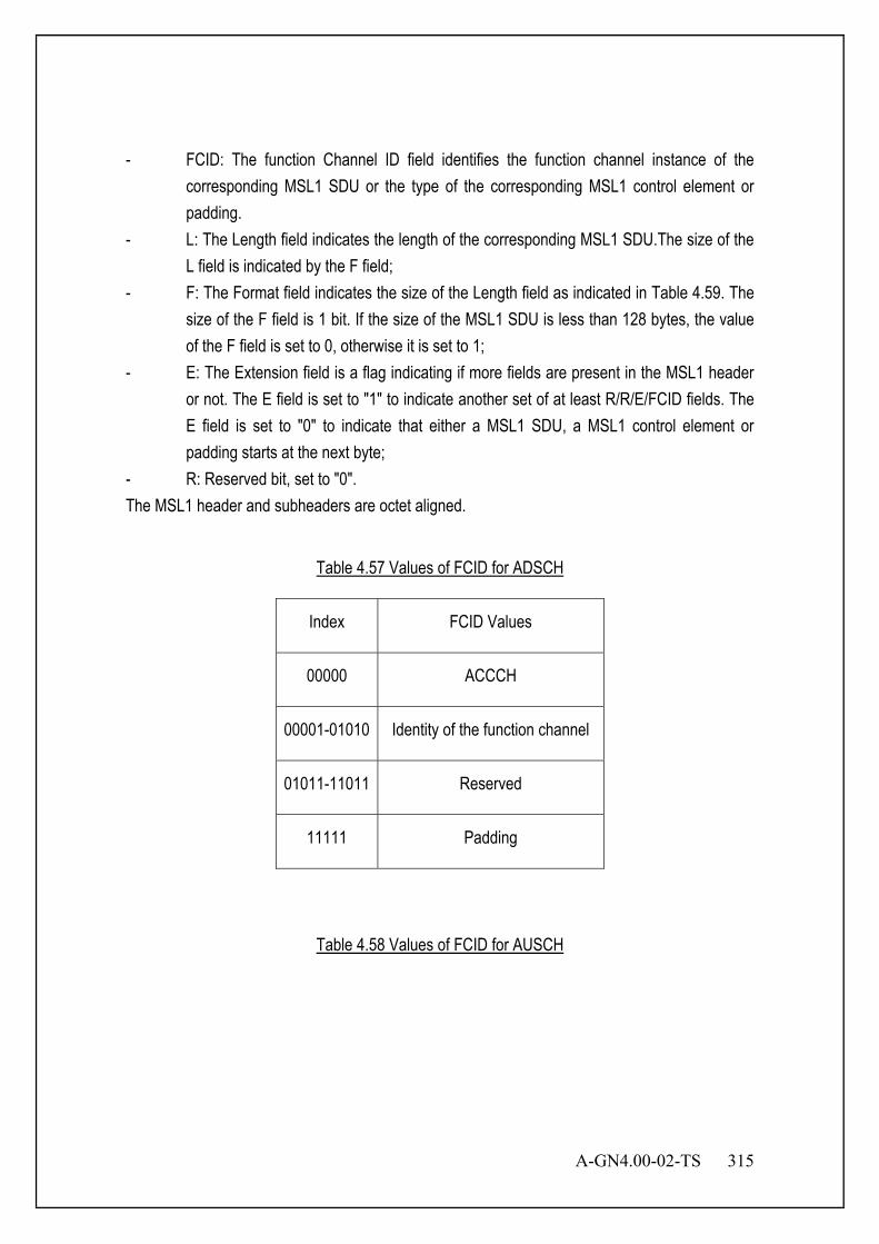
A-GN4.00-02-TS 315
- FCID: The function Channel ID field identifies the function channel instance of the corresponding MSL1 SDU or the type of the corresponding MSL1 control element or padding.
- L: The Length field indicates the length of the corresponding MSL1 SDU.The size of the L field is indicated by the F field;
- F: The Format field indicates the size of the Length field as indicated in Table 4.59. The size of the F field is 1 bit. If the size of the MSL1 SDU is less than 128 bytes, the value of the F field is set to 0, otherwise it is set to 1;
- E: The Extension field is a flag indicating if more fields are present in the MSL1 header or not. The E field is set to "1" to indicate another set of at least R/R/E/FCID fields. The E field is set to "0" to indicate that either a MSL1 SDU, a MSL1 control element or padding starts at the next byte;
- R: Reserved bit, set to "0". The MSL1 header and subheaders are octet aligned.
Table 4.57 Values of FCID for ADSCH
Index FCID Values
00000 ACCCH
00001-01010 Identity of the function channel
01011-11011 Reserved
11111 Padding
Table 4.58 Values of FCID for AUSCH

316 A-GN4.00-02-TS
Index FCID Values
00000 ACCCH
00001-01010 Identity of the function channel
01011-11001 Reserved
11010 Advanced Transmission Power Margin Notification Report
11011 C-MSID
11100 Truncated UL Data Size Notification
11101 Short UL Data Size Notification
11110 Long UL Data Size Notification
11111 Padding
Table 4.59 Values of F field:
Index Size of Length field (in bits)
0 7
1 15
4.6.3 MAC sub-layer2 (MSL2) MSL2 includs three kinds PDU, TMD PDU, UMD PDU and AMD PDU. The main services and functions of the MSL2 include:
A-GN4.00-02-TS 317
- Transfer of upper layer PDUs; - Error Correction through ARQ (only for AM data transfer); - Concatenation, segmentation and reassembly of MSL2 SDUs (only for UM and AM data
transfer); - Re-segmentation of MSL2 data PDUs (only for AM data transfer); - Reordering of MSL2data PDUs (only for UM and AM data transfer); - Duplicate detection (only for UM and AM data transfer); - Protocol error detection (only for AM data transfer); - MSL2 SDU discard (only for UM and AM data transfer); 4.6.3.1 TMD PDU TMD PDU consists only of a Data field and does not consist of any MSL2 headers. 4.6.3.2 UMD PDU UMD PDU consists of a Data field and an UMD PDU header. UMD PDU header consists of a fixed part (fields that are present for every UMD PDU) and an extension part (fields that are present for an UMD PDU when necessary). The fixed part of the UMD PDU header itself is byte aligned and consists of a FI, an E and a SN. The extension part of the UMD PDU header itself is byte aligned and consists of E(s) and LI(s). An UM MSL2 entity is configured by high layer to use either a 5 bit SN or a 10 bit SN. When the 5 bit SN is configured, the length of the fixed part of the UMD PDU header is one byte. When the 10 bit SN is configured, the fixed part of the UMD PDU header is identical to the fixed part of the AMD PDU header, except for D/C, RF and P fields all being replaced with R1 fields. The extension part of the UMD PDU header is identical to the extension part of the AMD PDU header (regardless of the configured SN size).
An UMD PDU header consists of an extension part only when more than one Data field elements are present in the UMD PDU, in which case an E and a LI are present for every Data field element except the last. Furthermore, when an UMD PDU header consists of an odd number of LI(s), four padding bits follow after the last LI.
4.6.3.3 AMD PDU

318 A-GN4.00-02-TS
AMD PDU is a kind of PDU of MSL2 and consists of a Data field and an AMD PDU header. AMD PDU header consists of a fixed part (fields that are present for every AMD PDU) and an extension part (fields that are present for an AMD PDU when necessary). The fixed part of the AMD PDU header itself is byte aligned and consists of a D/C, a RF, a P, a FI, an E and a SN. The extension part of the AMD PDU header itself is byte aligned and consists of E(s) and LI(s).
An AMD PDU header consists of an extension part only when more than one Data field elements are present in the AMD PDU, in which case an E and a LI are present for every Data field element except the last. Furthermore, when an AMD PDU header consists of an odd number of LI(s), four padding bits follow after the last LI.
4.6.3.4 AMD PDU segment AMD PDU segment consists of a Data field and an AMD PDU segment header. AMD PDU segment header consists of a fixed part (fields that are present for every AMD PDU segment) and an extension part (fields that are present for an AMD PDU segment when necessary). The fixed part of the AMD PDU segment header itself is byte aligned and consists of a D/C, a RF, a P, a FI, an E, a SN, a LSF and a SO. The extension part of the AMD PDU segment header itself is byte aligned and consists of E(s) and LI(s).
An AMD PDU segment header consists of an extension part only when more than one Data field elements are present in the AMD PDU segment, in which case an E and a LI are present for every Data field element except the last. Furthermore, when an AMD PDU segment header consists of an odd number of LI(s), four padding bits follow after the last LI.
4.6.3.5 State variables parameter and timers All state variables and all counters are non-negative integers. All state variables related to AM data transfer can take values from 0 to 1023. The transmitting side of each AM MSL2 entity shall maintain the following state variables: a) VT(A) – Acknowledgement state variable This state variable holds the value of the SN of the next AMD PDU for which a positive acknowledgment is to be received in-sequence, and it serves as the lower edge of the transmitting window. It is initially set to 0, and is updated whenever the AM MSL2 entity receives a positive acknowledgment for an AMD PDU with SN = VT(A). b) VT(MS) – Maximum send state variable

A-GN4.00-02-TS 319
This state variable equals VT(A) + AM_Window_Size, and it serves as the higher edge of the transmitting window. c) VT(S) – Send state variable This state variable holds the value of the SN to be assigned for the next newly generated AMD PDU. It is initially set to 0, and is updated whenever the AM MSL2 entity delivers an AMD PDU with SN = VT(S). d) POLL_SN – Poll send state variable This state variable holds the value of VT(S)-1 upon the most recent transmission of a MSL2 data PDU with the poll bit set to “1”. It is initially set to 0. The transmitting side of each AM MSL2 entity shall maintain the following counters: a) PDU_WITHOUT_POLL – Counter This counter is initially set to 0. It counts the number of AMD PDUs sent since the most recent poll bit was transmitted. b) BYTE_WITHOUT_POLL – Counter This counter is initially set to 0. It counts the number of data bytes sent since the most recent poll bit was transmitted. c) RETX_COUNT – Counter This counter counts the number of retransmissions of an AMD PDU (see subclause 5.2.1). There is one RETX_COUNT counter per PDU that needs to be retransmitted. The receiving side of each AM MSL2 entity shall maintain the following state variables: a) VR(R) – Receive state variable This state variable holds the value of the SN following the last in-sequence completely received AMD PDU, and it serves as the lower edge of the receiving window. It is initially set to 0, and is updated whenever the AM MSL2 entity receives an AMD PDU with SN = VR(R). b) VR(MR) – Maximum acceptable receive state variable This state variable equals VR(R) + AM_Window_Size, and it holds the value of the SN of the first AMD PDU that is beyond the receiving window and serves as the higher edge of the receiving window. c) VR(X) – t-Reordering state variable This state variable holds the value of the SN following the SN of the MSL2 data PDU which triggered t-Reordering.. d) VR(MS) – Maximum STATUS transmit state variable This state variable holds the highest possible value of the SN which can be indicated by “ACK_SN” when a STATUS PDU needs to be constructed. It is initially set to 0.

320 A-GN4.00-02-TS
e) VR(H) – Highest received state variable This state variable holds the value of the SN following the SN of the MSL2 data PDU with the highest SN among received MSL2 data PDUs. It is initially set to 0. The receiving side of each AM MSL2 entity shall maintain the following constant: a) AM_Window_Size This constant is used by both the transmitting side and the receiving side of each AM MSL2 entity to calculate VT(MS) from VT(A), and VR(MR) from VR(R). AM_Window_Size = 512. The receiving side of each AM MSL2 entity shall maintain the following timers: a) t-PollRetransmit This timer is used by the transmitting side of an AM MSL2 entity in order to retransmit a poll b) t-Reordering This timer is used by the receiving side of an AM MSL2 entity and receiving UM MSL2 entity in order to detect loss of MSL2 PDUs at lower layer. If t-Reordering is running, t-Reordering shall not be started additionally, i.e. only one t-Reordering per MSL2 entity is running at a given time. c) t-StatusProhibit This timer is used by the receiving side of an AM MSL2 entity in order to prohibit transmission of a STATUS PDU. 4.6.4 MAC sublayer 3 (MSL3) 4.6.4.1 Overview
This subclause provides an overview on services, functions and PDU structure provided by the MSL 3 sublayer. The main services and functions of the MSL 3 sublayer for the user plane include: - Header compression and decompression: ROHC only; - Transfer of user data; - In-sequence delivery of upper layer PDUs at MSL 3 re-establishment procedure for MSL 2 AM; - Duplicate detection of lower layer SDUs at MSL 3 re-establishment procedure for MSL 2 AM; - Retransmission of MSL 3 SDUs at handover for MSL 2 AM; - Ciphering and deciphering; - Timer-based SDU chuck in uplink. The main services and functions of the MSL 3 for the control plane include:
A-GN4.00-02-TS 321
- Ciphering and Integrity Protection; - Transfer of control plane data. 4.6.4.2 UL Data Transfer Procedures At reception of a MSL 3 SDU from upper layers, the MS shall: - start the chuck Timer associated with this MSL 3 SDU (if configured);
For a MSL 3 SDU received from upper layers, the MS shall: - associate the MSL 3 SN corresponding to Next_MSL 3_TX_SN to this MSL 3 SDU; - perform header compression of the MSL 3 SDU; - perform integrity protection (if needed), and ciphering (if needed) using COUNT based on
TX_HFN and the MSL 3 SN associated with this MSL 3 SDU respectively; - increment Next_MSL 3_TX_SN by one; - if Next_MSL 3_TX_SN > Maximum_MSL 3_SN: - set Next_MSL 3_TX_SN to 0; - increment TX_HFN by one; - submit the resulting MSL 3 Data PDU to lower layer. 4.6.4.3 DL Data Transfer Procedures
- chuck the MSL 3 Data PDUs that are received from lower layers due to the re-establishment of the lower layers; - process the MSL 3 Data PDUs that are received from lower layers due to the re-establishment of the lower layers, for both AM and UM; - reset the header compression protocol for downlink (if configured) , for both AM and UM; - set Next_ MSL 3_RX_SN, and RX_HFN to 0; - chuck all stored MSL 3 SDUs and MSL 3 PDUs; - apply the ciphering algorithm and key provided by upper layers during the re-establishment
procedure.
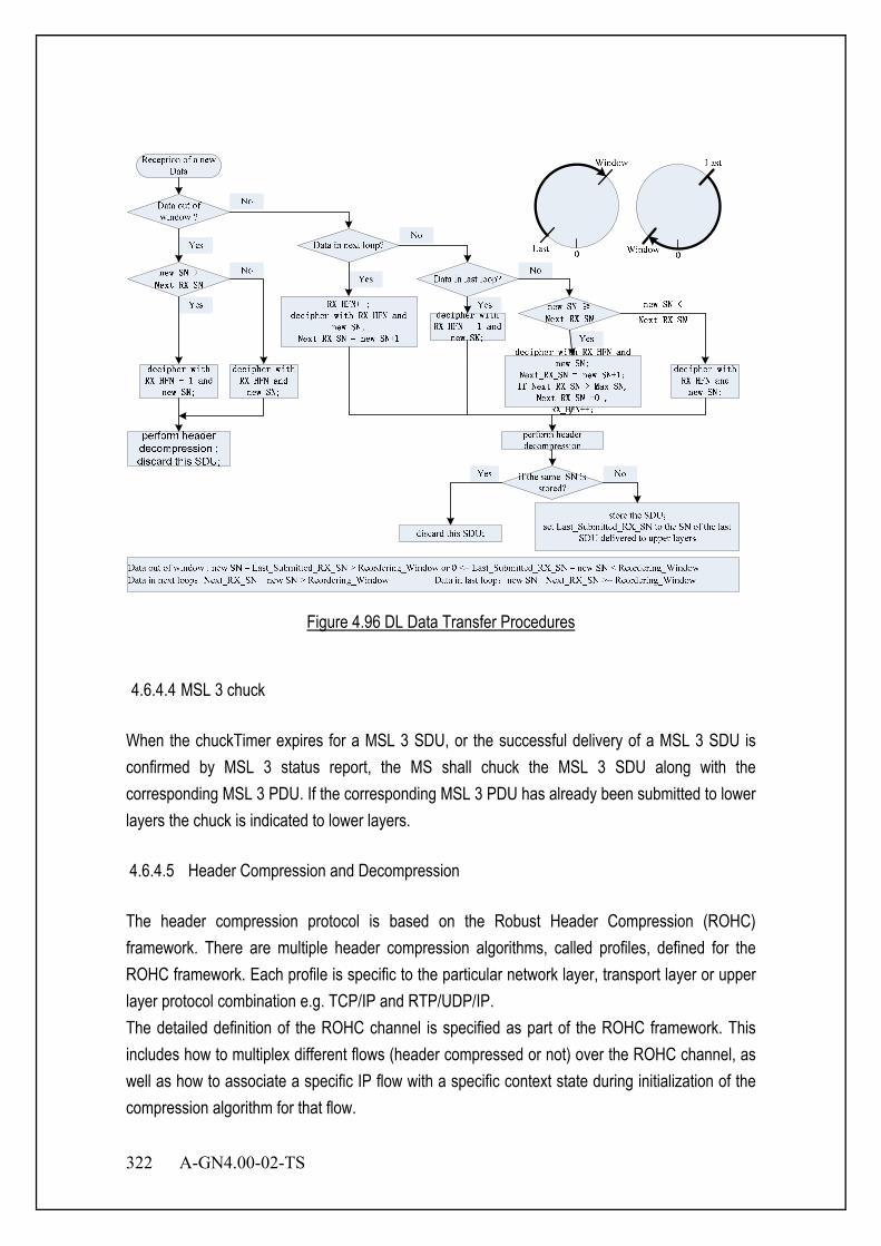
322 A-GN4.00-02-TS
Figure 4.96 DL Data Transfer Procedures
4.6.4.4 MSL 3 chuck
When the chuckTimer expires for a MSL 3 SDU, or the successful delivery of a MSL 3 SDU is confirmed by MSL 3 status report, the MS shall chuck the MSL 3 SDU along with the corresponding MSL 3 PDU. If the corresponding MSL 3 PDU has already been submitted to lower layers the chuck is indicated to lower layers. 4.6.4.5 Header Compression and Decompression The header compression protocol is based on the Robust Header Compression (ROHC) framework. There are multiple header compression algorithms, called profiles, defined for the ROHC framework. Each profile is specific to the particular network layer, transport layer or upper layer protocol combination e.g. TCP/IP and RTP/UDP/IP. The detailed definition of the ROHC channel is specified as part of the ROHC framework. This includes how to multiplex different flows (header compressed or not) over the ROHC channel, as well as how to associate a specific IP flow with a specific context state during initialization of the compression algorithm for that flow.
A-GN4.00-02-TS 323
4.6.4.6 Ciphering and Deciphering The ciphering function includes both ciphering and deciphering and is performed in MSL 3. For the control plane, the data unit that is ciphered is the data part of the MSL 3 PDU and the MAC-I. For the user plane, the data unit that is ciphered is the data part of the MSL 3 PDU; ciphering is not applicable to MSL 3 Control PDUs. The ciphering algorithm and key to be used by the MSL 3 entity are configured by upper layers. Meanwhile, the ciphering function is activated by upper layers. After security activation, the ciphering function shall be applied to all MSL 3 PDUs indicated by upper layers for the downlink and the uplink, respectively. 4.6.4.7 Integrity Protection and Verification
The integrity protection function includes both integrity protection and integrity verification and is performed in MSL 3 for MSL 3 entities associated with SRBs. The data unit that is integrity protected is the PDU header and the data part of the PDU before ciphering. The integrity protection algorithm and key to be used by the MSL 3 entity are configured by upper layers. Meanwhile, the integrity protection function is activated by upper layers. As the RADIO CONNECTION message which activates the integrity protection function is itself integrity protected with the configuration included in this RADIO CONNECTION message, this message needs first be decoded by RADIO CONNECTION before the integrity protection verification could be performed for the PDU in which the message was received. 4.6.4.8 Handling of unknown, unforeseen and erroneous protocol data When a MSL 3 entity receives a MSL 3 PDU that contains reserved or invalid values, the MSL 3 entity shall:
- chuck the received PDU.
4.6.4.9 Protocol data units, formats and parameters The MSL 3 Data PDU is used to convey: - a MSL 3 SDU SN; and - user plane data containing an uncompressed MSL 3 SDU; or - user plane data containing a compressed MSL 3 SDU; or - control plane data; and - a MAC-I field for SRBs only;
324 A-GN4.00-02-TS
The MSL 3 Control PDU is used to convey: - a MSL 3 status report indicating which MSL 3 SDUs are missing and which are not following a
MSL 3 re-establishment. - header compression control information, e.g. interspersed ROHC feedback. 4.6.4.10 Formats 4.6.4.10.1 General A MSL 3 PDU is a bit string that is byte aligned (i.e. multiple of 8 bits) in length. In the figures in sub clause 6.2, bit strings are represented by tables in which the most significant bit is the leftmost bit of the first line of the table, the least significant bit is the rightmost bit on the last line of the table, and more generally the bit string is to be read from left to right and then in the reading order of the lines. The bit order of each parameter field within a MSL 3 PDU is represented with the first and most significant bit in the leftmost bit and the last and least significant bit in the rightmost bit. MSL 3 SDUs are bit strings that are byte aligned (i.e. multiple of 8 bits) in length. A compressed or uncompressed SDU is included into a MSL 3 PDU from the first bit onward. 4.6.4.11 Parameters If not otherwise mentioned in the definition of each field then the bits in the parameters shall be interpreted as follows: the left most bit string is the first and most significant and the right most bit is the last and least significant bit. Unless otherwise mentioned, integers are encoded in standard binary encoding for unsigned integers. In all cases the bits appear ordered from MSB to LSB when read in the PDU.
4.6.4.12 State variables This sub clause describes the state variables used in MSL 3 entities in order to specify the MSL 3 protocol. All state variables are non-negative integers. The transmitting side of each MSL 3 entity shall maintain the following state variables: a) Next_ TX_SN The variable Next_ TX_SN indicates the MSL 3 SN of the next MSL 3 SDU for a given MSL 3 entity.
A-GN4.00-02-TS 325
b) TX_HFN The variable TX_HFN indicates the HFN value for the generation of the COUNT value used for MSL 3 PDUs for a given MSL 3 entity. The receiving side of each MSL 3 entity shall maintain the following state variables: c) Next_ RX_SN The variable Next_ RX_SN indicates the next expected MSL 3 SN by the receiver for a given MSL 3 entity. d) RX_HFN The variable RX_HFN indicates the HFN value for the generation of the COUNT value used for the received MSL 3 PDUs for a given MSL 3 entity. e) Last_Submitted_ RX_SN For MSL 3 entities for DRBs mapped on MSL 2 AM the variable Last_Submitted_RX_SN indicates the SN of the last MSL 3 SDU delivered to the upper layers. 4.6.4.13 Timers
The transmitting side of each MSL 3 entity for DRBs shall maintain the following timers: chuckTimer The duration of the timer is configured by upper layers. In the transmitter, a new timer is started upon reception of an SDU from upper layer. 4.6.4.14 Constants a) Reordering_Window Indicates the size of the reordering window. The size equals to 2048, i.e. half of the MSL 3 SN space, for radio bearers that are mapped on MSL 2 AM. b) Maximum_MSL 3_SN is: - 4095 if the MSL 3 entity is configured for the use of 12 bit SNs - 127 if the MSL 3 entity is configured for the use of 7 bit SNs - 31 if the MSL 3 entity is configured for the use of 5 bit SNs

326 A-GN4.00-02-TS
Chapter 5 Common Channel Specification
5.1 Overview In this chapter, common channel (CCH) to apply to link establishment control is specified. The structure of PHY layer, logical common channel (LCCH) structural methods and control message format are clarified. 5.2 Common Channel (CCH) CCH consists of BCCH, PCH, TCCH and SCCH as shown in Figure 5.1.
CCH Common Channel
Broadcast Control Channel
Paging Channel
Signaling Control Channel
Timing Correct Channel TCCH
BCCH
PCH
SCCH
Figure 5.1 CCH Structure
The function of CCH is summarized in Table 5.1.
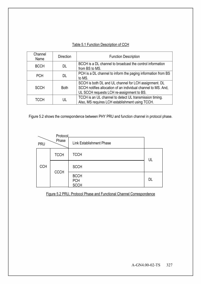
A-GN4.00-02-TS 327
Table 5.1 Function Description of CCH
Channel Name Direction Function Description
BCCH DL BCCH is a DL channel to broadcast the control information from BS to MS.
PCH DL PCH is a DL channel to inform the paging information from BS to MS.
SCCH Both SCCH is both DL and UL channel for LCH assignment. DL SCCH notifies allocation of an individual channel to MS. And, UL SCCH requests LCH re-assignment to BS.
TCCH UL TCCH is an UL channel to detect UL transmission timing. Also, MS requires LCH establishment using TCCH.
Figure 5.2 shows the correspondence between PHY PRU and function channel in protocol phase.
Figure 5.2 PRU, Protocol Phase and Functional Channel Correspondence
Protocol Phase
CCH
TCCH
CCCH
Link Establishment Phase PRU
UL
DL
TCCH
SCCH
BCCH PCH SCCH

328 A-GN4.00-02-TS
5.2.1 Logical Common Channel (LCCH) Rules of the structure of logical common channel (LCCH) are shown in Figure 5.3.
Subchannel of CCH
Downlink LCCH
Uplink LCCH
Slot for Downlink CCH
Slot for Uplink CCH
LCCH superframe
(5×n×m) ms
Uplink Downlink
TDMA frame 5 ms
Interval time for downlink transmission
(5×n) ms
Slot 1 2 3 4 1 2 3 4 1 2 3 4 1 2 3 4
1 2 3 4
1 2 3 4
m 1 2 3
m 1 2 3
4 1 2 3 4 1 2 3 4
n is LCCH interval value. Refer to Section 5.2.3.1.
Figure 5.3 Slot and LCCH
LCCH has the superframe structure shown in Section 5.2.3. All transmission/reception timing of slots for controlling intermittent transmission and so forth is generated based on the superframe.
A-GN4.00-02-TS 329
5.2.2 Definition of Superframe The minimum cycle of the DL LCCH that specifies the slot position of all LCCH elements is specified as the LCCH superframe. As DL LCCH elements, there are three types of LCCH elements: They are BCCH, which is used by the appropriate system, all PCH (P1-Pk: Number of groups = k) corresponding to the paging group as well as the SCCH with fixed insertion. BCCH(A) must be transmitted by the lead slot of the LCCH superframe. The leading position of the superframe is reported via BCCH transmission. Also, BCCH(B) is defined by something other than the superframe lead. 5.2.3 Superframe Structure of DL LCCH The superframe structure of the DL LCCH that is defined by profile data is informed to each MS on BCCH. Depending on the way to select the profile data that defines the structure, the LCCH superframe can transmit the identical paging group(pi: i = 1 to k) multiple times, but the number of continuous transmissions (provided by nBS) for one paging call and the number of same paging groups nSG included in the LCCH superframe are independent. Continuous transmission in response to one paging call can be concluded within the LCCH superframe, or it can be spread over several superframes. If necessary, it is possible to temporarily replace LCCH elements except for BCCH (A), and send the other LCCH elements. Otherwise, the frame basic unit must follow the rules below.
(a) Within one frame basic unit, regularly intermittently transmitted BCCH or SCCH appears first, and PCH is established as the function channel that follows it.
(b) Within one frame basic unit, if nPCH data is greater than or equal to two, the respective PCHs are continuously established.
Further, during system operation, if profile data is modified, it is necessary to control information flow and contents so that all MSs can receive those modified contents. Specific profile data are shown below. 5.2.3.1 LCCH Interval Value (n) LCCH interval value shows the cycle in which BS intermittently transmits an LCCH slot. It is the value expressed by the number of TDMA frames (n) within the intermittent transmission cycle.
330 A-GN4.00-02-TS
5.2.3.2 Frame Basic Unit Length (nSUB) This stands for the length of the LCCH superframe, which constitutes consecutive elements of BCCH, SCCH and PCH. This LCCH superframe constituent element is called the frame basic unit. 5.2.3.3 Number of Same Paging Groups (nSG) This stands for the number of times that the same paging group is repeatedly transmitted in one superframe. 5.2.3.4 PCH Number (nPCH) This stands for the number of PCH signal elements in a frame basic unit. 5.2.3.5 Paging Grouping Factor (nGROUP) This stands for the number of frame basic units required for one transmission of each PCH belonging to all paging groups in one superframe. Furthermore the multiple (nGROUP) of the number of PCHs (nPCH) is specified as the group division number of PCH information. However, when the PCH paging groups are mutually related as two LCCH are used, number of group division is calculated as nGROUP×nPCH×2. 5.2.3.6 Battery Saving Cycle Maximum value (nBS) nBS stands for the number of times that BS continuously transmits the identical reception signal to a certain paging group. The maximum battery saving cycles of MS that are permitted by the system depending on nBS are specified. (Maximum battery saving cycle = 5 ms × n × nSUB × nGROUP × nBS)

A-GN4.00-02-TS 331
5.2.3.7 The Relationship Among Profile Data The relationship among profile data are shown below. nSUB ≥ nPCH + 1 In the frame basic unit, nPCH + 1 is the lowest frame basic unit
length because BCCH is always assigned. N = nSG×nGROUP The number of frame basic units N within an LCCH superframe is
given by the product of the number of the same paging groups nSG and the paging grouping factor nGROUP.
(Units are frame basic units) nFRM ≤(≥) nGROUP×nBS If the number of the same paging groups nSG in the LCCH
superframe is the same as the battery saving cycle maximum value nBS, there will be an equal sign. In other cases, there will not be an equal sign. Left side: Number of frame basic units in LCCH superframe Right side: Maximum battery saving cycle (The unit is referred to as the frame basic unit.)
LCCH Downlink
BCCH
PCH1
PCH2
SCCH
PCH3
PCH4
LCCH superframe
(5 × n) ms
nSUB
nSUB×nGROUP
SCCH
PCH2
SCCH
SCCH
BCCH
PCH5
PCH6
PCH7
PCH8
PCH1
The diagram above shows an example in which nSG=1, nSUB=3, nPCH=2, nGROUP=4
Figure 5.4 An Example of LCCH Structure
5.2.3.8 Paging Group Calculation Rules From the information on Paging ID and BCCH, PCH which should be received is computable with the following formula. Refer to Section 5.5.4 for Paging ID.
[Paging Group formula] Paging Group = (Paging ID) MOD (nPCH × nGROUP) + 1
Paging ID : Identification information for paging nPCH : Number of PCHs in the frame basic unit
nGROUP : Paging grouping factor
332 A-GN4.00-02-TS
5.2.3.9 Optional Paging Group Calculation Rules The MS may use Discontinuous Reception (DRX) in idle mode in order to reduce power consumption. One Paging Occasion (PO) is a slot where there may be P-MSID transmitted on ADECCH addressing the paging message. One Paging Frame (PF) is one Radio Frame, which may contain one or multiple Paging Occasion(s). When DRX is used the MS needs only to monitor one PO per DRX. PF and PO is determined by following formulae using the DRX parameters provided in System Information: PF is given by following equation: SFN mod T= (T div N)*(MS_ID mod N) Index i_s pointing to PO from slot pattern will be derived from following calculation: i_s = floor(MS_ID/N) mod Ns The index i-s position to PO should meet the following subframe pattern: when i_s is 0, the PO will be in subframe #0; when i_s is 1 and Ns is 2, the PO will be in subframe #5; when i_s is 1 and Ns is 4, the PO will be in subframe #1; when i_s is 2 and Ns is 4, the PO will be in subframe #5 and when i_s is 3 and Ns is 4, the PO will be in subframe #6. System Information DRX parameters stored in the MS shall be updated locally in the MS whenever the DRX parameter values are changed in SI. The following Parameters are used for the calculation of the PF and i_s: - T: DRX cycle of the MS. T is determined by the shortest of the MS specific DRX value, if allocated by upper layers, and a default DRX value broadcast in system information. If MS specific DRX is not configured by upper layers, the default value is applied. - nB: 4T, 2T, T, T/2, T/4, T/8, T/16, T/32. - N: min(T,nB); - Ns: max(1,nB/T) - MS_ID: IMSI mod 1024. IMSI is given as sequence of digits of type Integer (0..9), IMSI shall in the formulae above be interpreted as a decimal integer number, where the first digit given in the sequence represents the highest order digit. For example: IMSI = 12 (digit1=1, digit2=2) In the calculations, this shall be interpreted as the decimal integer "12", not "1x16+2 = 18". 5.2.3.10 Intermittent Transmission Timing for ICH Figure 5.5 shows the intermittent transmission timing of ICH according to the ICH offset and the ICH period. ICH offset indicates the beginning frame of ICH based on the CCH frame. ICH period indicates the cycle of ICH based on the beginning frame by ICH offset. However, the intermittent transmission timing of ICH must always be adjusted according to the beginning frame of ICH based on the CCH frame. Refer to Section 5.5.6.1.3 for information elements of the ICH offset and the ICH period.

A-GN4.00-02-TS 333
ULDL
ULDL
5 ms
ICH period
ICH
CCH
Assigned ICH ICH period
Interval time for downlink transmission (5 × n) ms
ICH offset n is LCCH interval value. Refer to Section 5.2.3.1.
Figure 5.5 Intermittent Transmission Timing for ICH
5.2.4 Structure of UL LCCH The UL LCCH is sent from each MS only when needed. It is used as the UL slot 2.5 ms before the DL LCCH. Refer to Figure 5.3. 5.2.5 Structure of DL LCCH A standard structural example of the DL LCCH is shown in Figure 5.6.
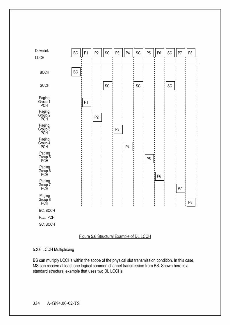
334 A-GN4.00-02-TS
P2 P1 P3 SC P4 P6 P5 P7 SC P8 Downlink LCCH
BCCH
SCCH SC
Paging Group 1
PCH P1
Paging Group 2
PCH P2
Paging Group 3
PCH P3
Paging Group 4
PCH P4
BC: BCCH Pnum: PCH SC: SCCH
Paging Group 5
PCH P5
Paging Group 6
PCH P6 Paging Group 7
PCH P7
Paging Group 8
PCH P8
SC BC
BC
SC SC
Figure 5.6 Structural Example of DL LCCH
5.2.6 LCCH Multiplexing BS can multiply LCCHs within the scope of the physical slot transmission condition. In this case, MS can receive at least one logical common channel transmission from BS. Shown here is a standard structural example that uses two DL LCCHs.

A-GN4.00-02-TS 335
5.2.6.1 When PCH Paging Groups Being Independent The PCH paging group of the LCCHs f1 and f2 are mutually independent, but each DL LCCH superframe structure is identical. Refer to Section 5.5.2.1 for n1offset and noffset.
BC P1 P2 SC P3 P4 BC
BC P1 P2 SC P3 P4 BC
. . .
. . .
LCCH superframe
LCCH superframe
(5 x noffset) ms
BC :BCCH Pnum :PCH SC :SCCH
f1
f2
(5 x n) ms
Here, an example is shown for the case where two LCCH are the same absolute slot.
Figure 5.7 Example of Multiplex for Independent LCCH
5.2.6.2 When PCH Paging Groups Being Inter-related LCCH f1's PCH transmits odd-numbered groups, and f2 transmits even-numbered groups.
BC P1 P3 SC P5 P7 BC
BC P2 P4 SC P6 P8 BC
. . .
. . .
LCCH superframe
LCCH superframe
(5 x noffset) ms
BC :BCCH Pnum :PCH SC :SCCH
f1
f2
(5 x n) ms
Here, an example is shown for the case where two LCCH are the same absolute slot.
Figure 5.8 Example of Multiplex for Inter-related LCCH
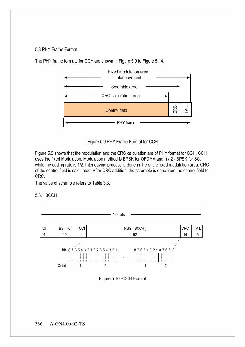
336 A-GN4.00-02-TS
5.3 PHY Frame Format The PHY frame formats for CCH are shown in Figure 5.9 to Figure 5.14.
Figure 5.9 PHY Frame Format for CCH
Figure 5.9 shows that the modulation and the CRC calculation are of PHY format for CCH. CCH uses the fixed Modulation. Modulation method is BPSK for OFDMA and π / 2 - BPSK for SC, while the coding rate is 1/2. Interleaving process is done in the entire fixed modulation area. CRC of the control field is calculated. After CRC addition, the scramble is done from the control field to CRC. The value of scramble refers to Table 3.3. 5.3.1 BCCH
CI 4
BS-Info 40
MSG ( BCCH ) 92
CRC 16
TAIL 6
162 bits
CCI 4
Octet 2 1 12
Bit 8 1 7 5 4 3 2 6
11
….. 8 1 7 5 4 3 2 6 8 1 7 5 4 3 2 6 5 6 8 7
Figure 5.10 BCCH Format
PHY frame
CRC
TAIL
Control field
CRC calculation area
Scramble area
Fixed modulation area Interleave unit

A-GN4.00-02-TS 337
5.3.2 PCH
CI 4
BS-Info 40
MSG ( PCH ) 92
CRC 16
TAIL 6
162 bits
CCI 4
Octet 2 1 12
Bit 8 1 7 5 4 3 2 6
11
….. 8 1 7 5 4 3 2 6 8 1 7 5 4 3 2 6 5 6 8 7
Figure 5.11 PCH Format
5.3.3 TCCH TCCH is a signal pattern. It is defined as timing correct channel at Sections 3.5.5 and 3.6.6. 5.3.4 SCCH 5.3.4.1 DL SCCH
CI 4
BS-Info 40
MSG ( SCCH ) 92
CRC 16
TAIL 6
162 bits
CCI 4
Octet 2 1 12
Bit 8 1 7 5 4 3 2 6
11
….. 8 1 7 5 4 3 2 6 8 1 7 5 4 3 2 6 5 6 8 7
Figure 5.12 DL SCCH Format

338 A-GN4.00-02-TS
5.3.4.2 UL SCCH for OFDMA
CI 4
BSID nBL
MSG ( SCCH ) 102 - nBL
CRC 16
TAIL 6
162 bits
MSID 34
Octet 2 1
Bit 8 1 7 5 4 3 2 6 …
n
….. 8 1 7 5 4 3 2 6
n - 1
8 1 7 5 4 3 2 6
Refer to Section 5.5.2.1 for nBL.
Figure 5.13 UL SCCH Format for OFDMA
5.3.4.3 UL SCCH for SC
CI 4
BSID nBL
MSG ( SCCH ) 60 - nBL
CRC 16
TAIL 6
120 bits
MSID 34
Octet 2 1
Bit 8 1 7 5 4 3 2 6 …
n
….. 8 1 7 5 4 3 2 6
n - 1
8 1 7 5 4 3 2 6
Refer to Section 5.5.2.1 for nBL.
Figure 5.14 UL SCCH Format for SC (without virtual GI extension)
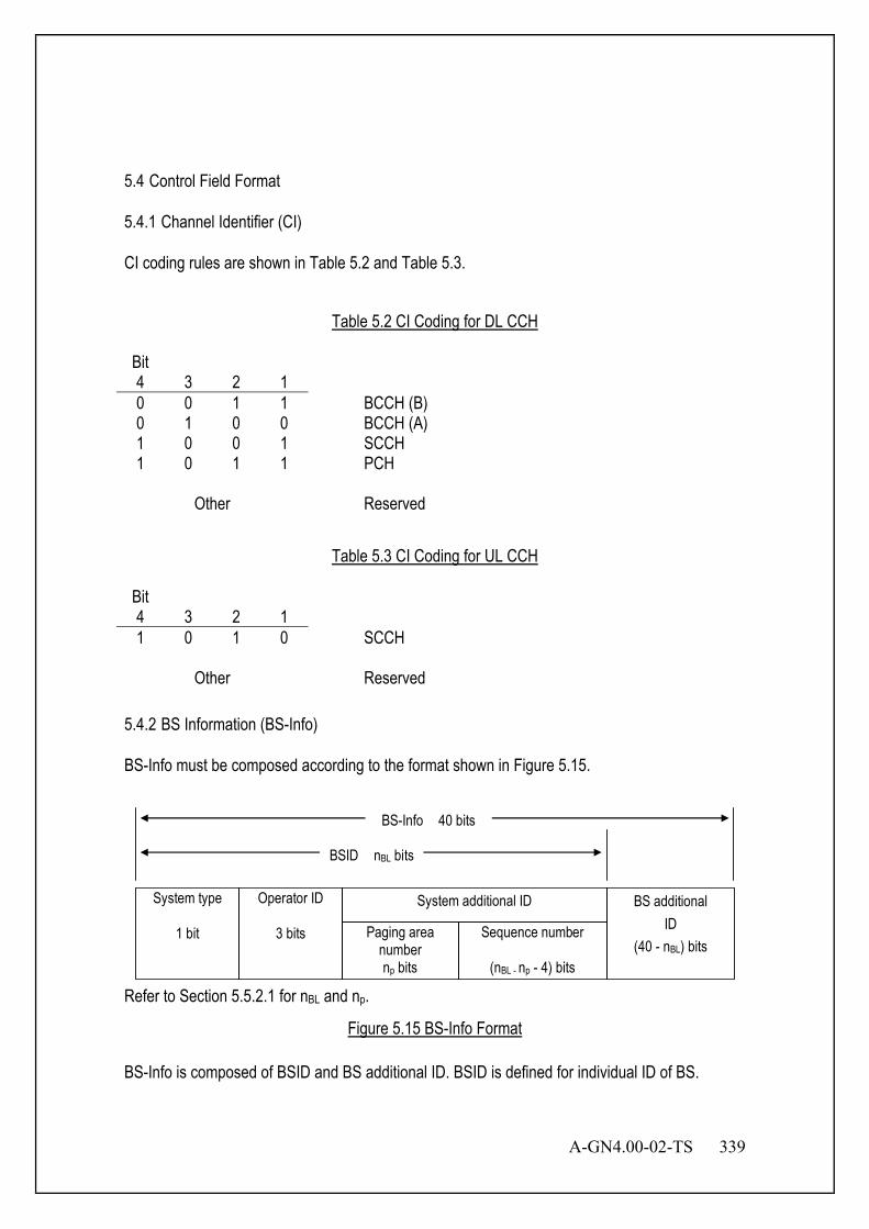
A-GN4.00-02-TS 339
5.4 Control Field Format 5.4.1 Channel Identifier (CI) CI coding rules are shown in Table 5.2 and Table 5.3.
Table 5.2 CI Coding for DL CCH
Bit 4 3 2 1
0 0 1 1 BCCH (B) 0 1 0 0 BCCH (A) 1 0 0 1 SCCH 1 0 1 1 PCH
Other Reserved
Table 5.3 CI Coding for UL CCH
Bit 4 3 2 1
1 0 1 0 SCCH
Other Reserved 5.4.2 BS Information (BS-Info) BS-Info must be composed according to the format shown in Figure 5.15.
System type
1 bit
Operator ID
3 bits
BS-Info 40 bits
Paging area number np bits
System additional ID
Sequence number
(nBL - np - 4) bits
BS additional ID
(40 - nBL) bits
BSID nBL bits
Refer to Section 5.5.2.1 for nBL and np.
Figure 5.15 BS-Info Format
BS-Info is composed of BSID and BS additional ID. BSID is defined for individual ID of BS.
340 A-GN4.00-02-TS
5.4.2.1 Base Station ID (BSID) The area of BSID is indicated in the BSID area bit length (nBL) as "radio channel information broadcasting" message on BCCH. The following information elements are included in BSID. 5.4.2.1.1 System Type The system type is indicated in public system.
Table 5.4 System Type
Bit 1
0 Reserved 1 Public system
5.4.2.1.2 Operator ID Operator ID length is three bits. The allocation of the bit is separately specified. 5.4.2.1.3 System Additional ID The system additional ID is composed of the paging area number and the sequence number. The area of paging area number is indicated in the paging area number length (np) as "radio channel information broadcasting" message on BCCH. 5.4.2.1.3.1 Paging Area Number Paging area is identified by paging area number. 5.4.2.1.3.2 Sequence Number BS is identified by sequence number. 5.4.2.2 BS Additional ID BS additional ID is an area to notify of the function of each BS.
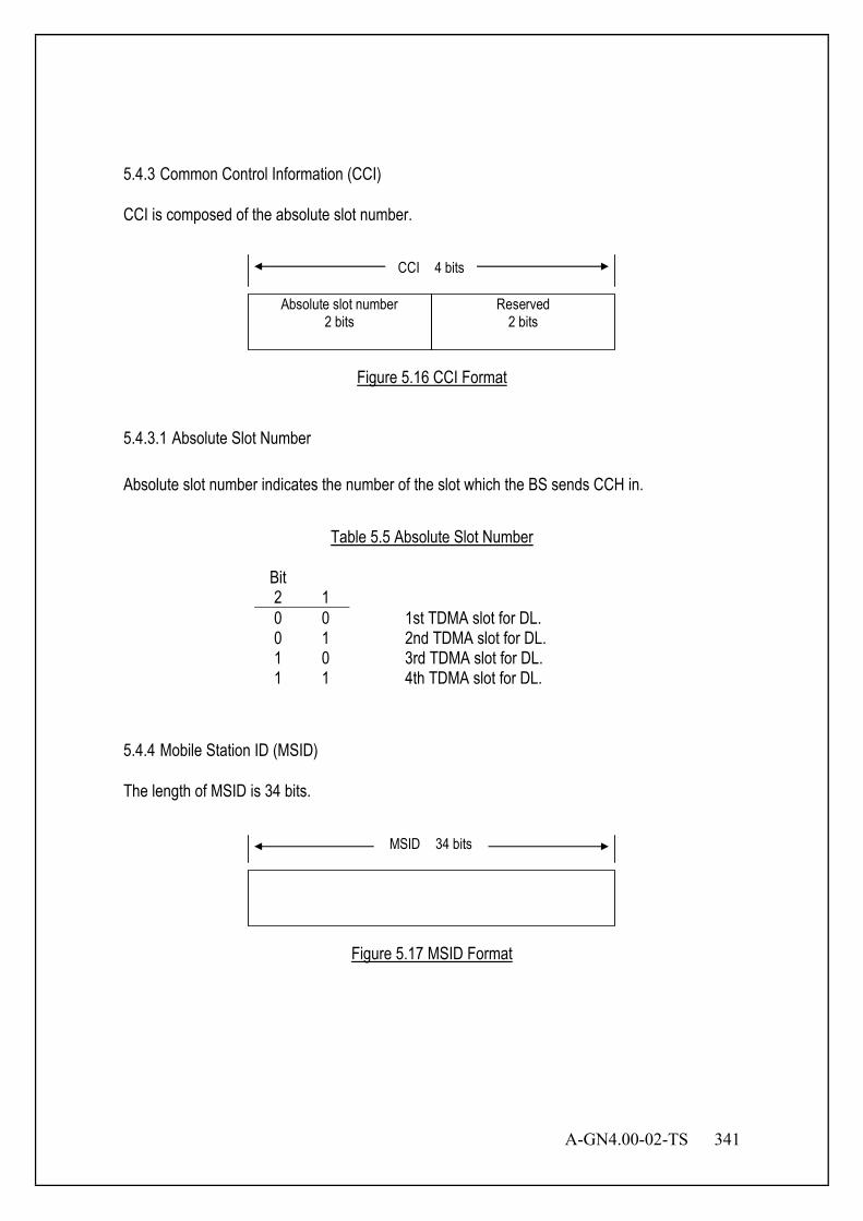
A-GN4.00-02-TS 341
5.4.3 Common Control Information (CCI) CCI is composed of the absolute slot number.
Absolute slot number 2 bits
Reserved 2 bits
CCI 4 bits
Figure 5.16 CCI Format
5.4.3.1 Absolute Slot Number Absolute slot number indicates the number of the slot which the BS sends CCH in.
Table 5.5 Absolute Slot Number
Bit 2 1
0 0 1st TDMA slot for DL. 0 1 2nd TDMA slot for DL. 1 0 3rd TDMA slot for DL. 1 1 4th TDMA slot for DL.
5.4.4 Mobile Station ID (MSID) The length of MSID is 34 bits.
MSID 34 bits
Figure 5.17 MSID Format
342 A-GN4.00-02-TS
5.5 MSG Field 5.5.1 Message Type List A list of messages defined in the MSG field is shown in Table 5.6.
Table 5.6 Message for MSG Field
Message for MSG (BCCH) Reference "Radio channel information broadcasting" message "System information broadcasting" message "Optional information broadcasting" message
5.5.2.1 5.5.2.2 5.5.2.3
Message for MSG (PCH) Reference “No Paging” message "Paging type 1" message "Paging type 2" message "Paging type 3" message "Paging type 4" message "Paging type 5" message "Paging type 6" message "Paging type 7" message
5.5.4.1 5.5.4.2 5.5.4.3 5.5.4.4 5.5.4.5 5.5.4.6 5.5.4.7 5.5.4.8
Message for MSG (SCCH) Reference "Idle" message "LCH assignment 1" message "LCH assignment 2" message "LCH assignment 3" message "LCH assignment standby" message "LCH assignment reject" message "LCH assignment re-request" message
5.5.6.1.1 5.5.6.1.2 5.5.6.1.3 5.5.6.1.4 5.5.6.1.5 5.5.6.1.6 5.5.6.2.1
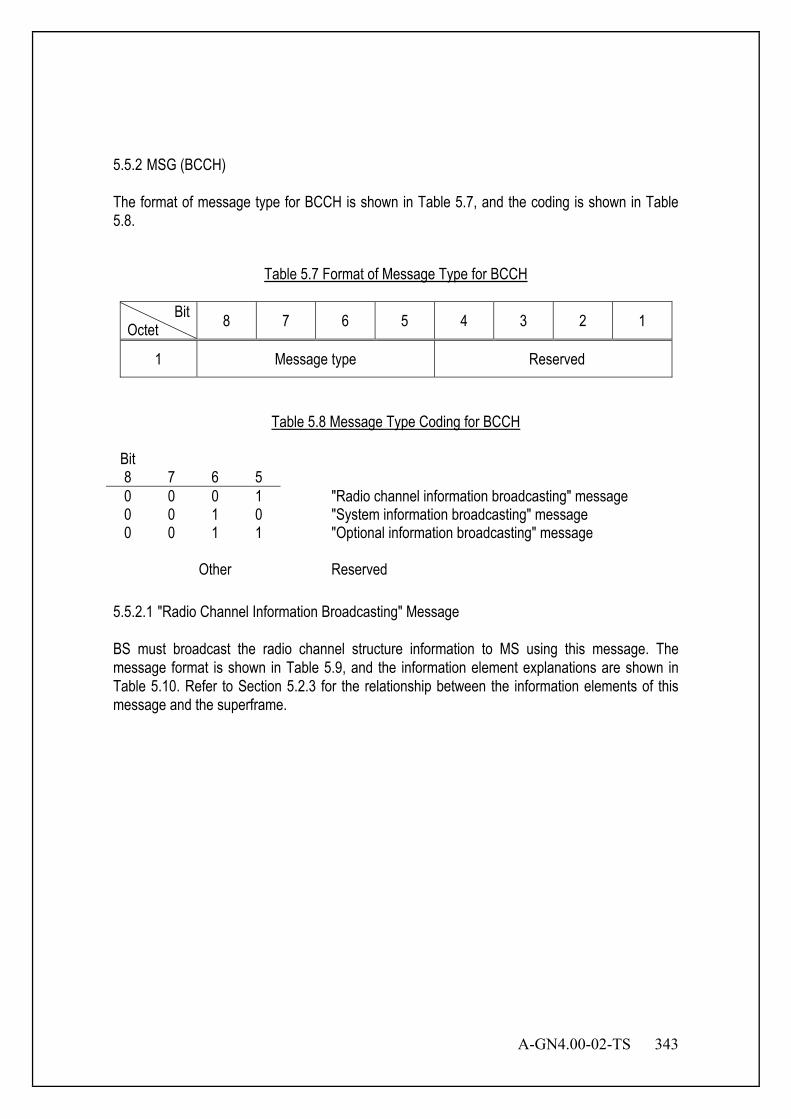
A-GN4.00-02-TS 343
5.5.2 MSG (BCCH) The format of message type for BCCH is shown in Table 5.7, and the coding is shown in Table 5.8.
Table 5.7 Format of Message Type for BCCH
Bit Octet 8 7 6 5 4 3 2 1
1 Message type Reserved
Table 5.8 Message Type Coding for BCCH
Bit 8 7 6 5
0 0 0 1 "Radio channel information broadcasting" message 0 0 1 0 "System information broadcasting" message 0 0 1 1 "Optional information broadcasting" message
Other Reserved 5.5.2.1 "Radio Channel Information Broadcasting" Message BS must broadcast the radio channel structure information to MS using this message. The message format is shown in Table 5.9, and the information element explanations are shown in Table 5.10. Refer to Section 5.2.3 for the relationship between the information elements of this message and the superframe.
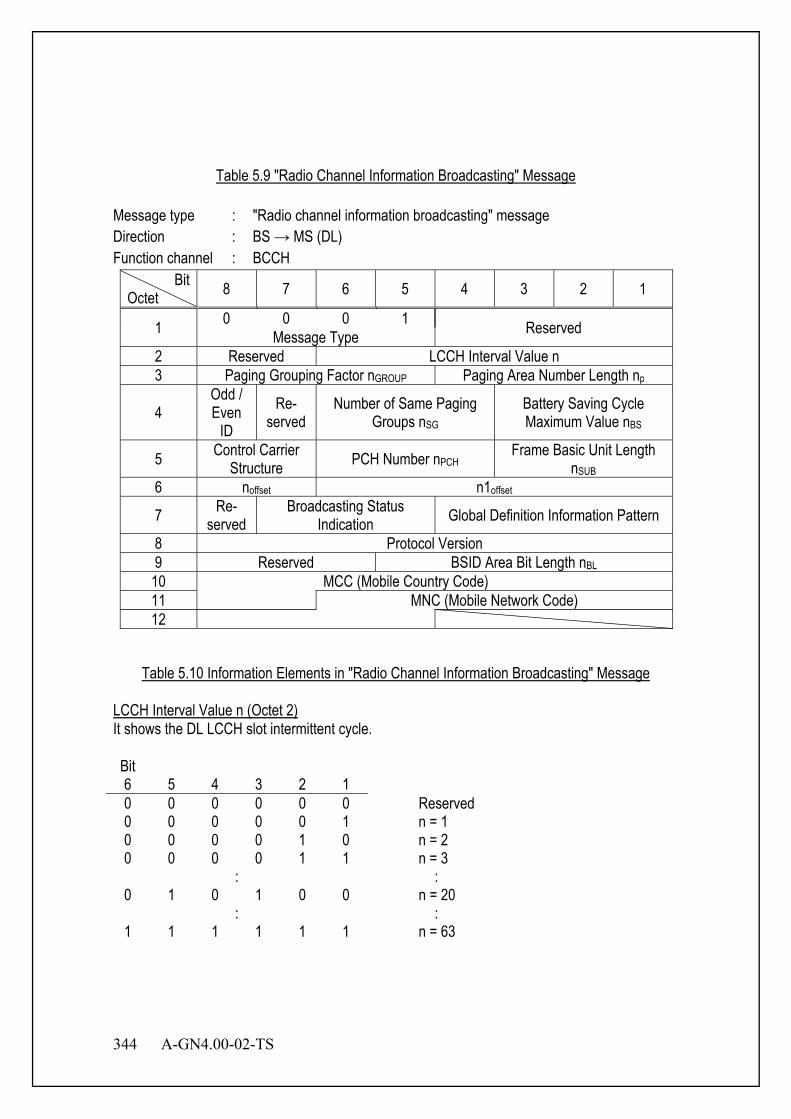
344 A-GN4.00-02-TS
Table 5.9 "Radio Channel Information Broadcasting" Message
Message type : "Radio channel information broadcasting" message Direction : BS → MS (DL) Function channel : BCCH
Bit Octet 8 7 6 5 4 3 2 1
1 0 0 0 1 Reserved Message Type 2 Reserved LCCH Interval Value n 3 Paging Grouping Factor nGROUP Paging Area Number Length np
4 Odd / Even
ID Re-
served Number of Same Paging
Groups nSG Battery Saving Cycle Maximum Value nBS
5 Control Carrier Structure PCH Number nPCH Frame Basic Unit Length
nSUB 6 noffset n1offset
7 Re- served
Broadcasting Status Indication Global Definition Information Pattern
8 Protocol Version 9 Reserved BSID Area Bit Length nBL 10 MCC (Mobile Country Code) 11 MNC (Mobile Network Code) 12
Table 5.10 Information Elements in "Radio Channel Information Broadcasting" Message
LCCH Interval Value n (Octet 2) It shows the DL LCCH slot intermittent cycle. Bit 6 5 4 3 2 1
0 0 0 0 0 0 Reserved 0 0 0 0 0 1 n = 1 0 0 0 0 1 0 n = 2 0 0 0 0 1 1 n = 3
: : 0 1 0 1 0 0 n = 20
: : 1 1 1 1 1 1 n = 63
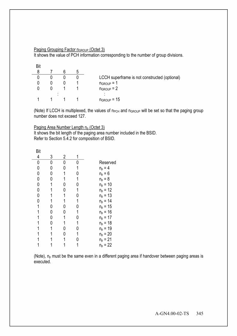
A-GN4.00-02-TS 345
Paging Grouping Factor nGROUP (Octet 3) It shows the value of PCH information corresponding to the number of group divisions. Bit 8 7 6 5
0 0 0 0 LCCH superframe is not constructed (optional) 0 0 0 1 nGROUP = 1 0 0 1 1 nGROUP = 2
: : 1 1 1 1 nGROUP = 15
(Note) If LCCH is multiplexed, the values of nPCH and nGROUP will be set so that the paging group number does not exceed 127. Paging Area Number Length np (Octet 3) It shows the bit length of the paging area number included in the BSID. Refer to Section 5.4.2 for composition of BSID. Bit 4 3 2 1
0 0 0 0 Reserved 0 0 0 1 np = 4 0 0 1 0 np = 6 0 0 1 1 np = 8 0 1 0 0 np = 10 0 1 0 1 np = 12 0 1 1 0 np = 13 0 1 1 1 np = 14 1 0 0 0 np = 15 1 0 0 1 np = 16 1 0 1 0 np = 17 1 0 1 1 np = 18 1 1 0 0 np = 19 1 1 0 1 np = 20 1 1 1 0 np = 21 1 1 1 1 np = 22
(Note), np must be the same even in a different paging area if handover between paging areas is executed.
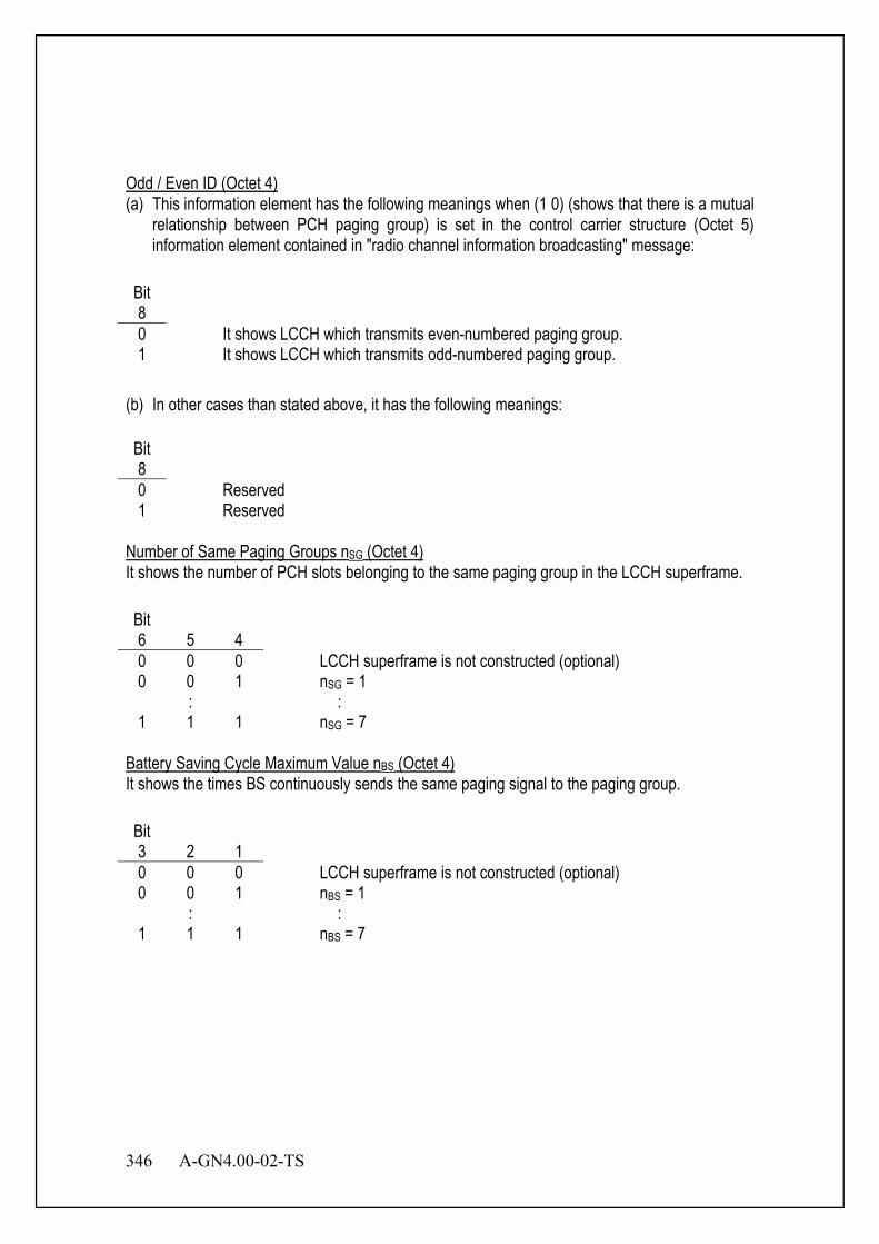
346 A-GN4.00-02-TS
Odd / Even ID (Octet 4) (a) This information element has the following meanings when (1 0) (shows that there is a mutual
relationship between PCH paging group) is set in the control carrier structure (Octet 5) information element contained in "radio channel information broadcasting" message:
Bit 8
0 It shows LCCH which transmits even-numbered paging group. 1 It shows LCCH which transmits odd-numbered paging group.
(b) In other cases than stated above, it has the following meanings: Bit 8
0 Reserved 1 Reserved
Number of Same Paging Groups nSG (Octet 4) It shows the number of PCH slots belonging to the same paging group in the LCCH superframe. Bit 6 5 4
0 0 0 LCCH superframe is not constructed (optional) 0 0 1 nSG = 1
: : 1 1 1 nSG = 7
Battery Saving Cycle Maximum Value nBS (Octet 4) It shows the times BS continuously sends the same paging signal to the paging group. Bit 3 2 1
0 0 0 LCCH superframe is not constructed (optional) 0 0 1 nBS = 1
: : 1 1 1 nBS = 7
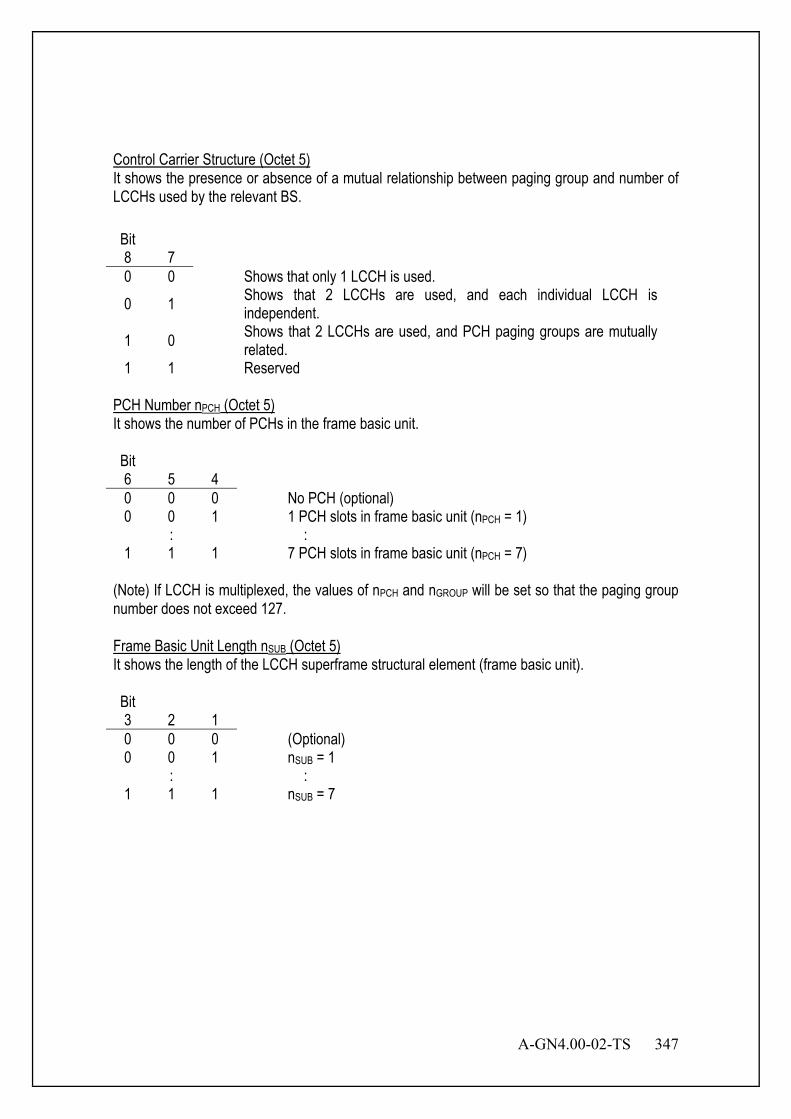
A-GN4.00-02-TS 347
Control Carrier Structure (Octet 5) It shows the presence or absence of a mutual relationship between paging group and number of LCCHs used by the relevant BS. Bit 8 7
0 0 Shows that only 1 LCCH is used. 0 1 Shows that 2 LCCHs are used, and each individual LCCH is
independent. 1 0 Shows that 2 LCCHs are used, and PCH paging groups are mutually
related. 1 1 Reserved
PCH Number nPCH (Octet 5) It shows the number of PCHs in the frame basic unit. Bit 6 5 4
0 0 0 No PCH (optional) 0 0 1 1 PCH slots in frame basic unit (nPCH = 1)
: : 1 1 1 7 PCH slots in frame basic unit (nPCH = 7)
(Note) If LCCH is multiplexed, the values of nPCH and nGROUP will be set so that the paging group number does not exceed 127. Frame Basic Unit Length nSUB (Octet 5) It shows the length of the LCCH superframe structural element (frame basic unit). Bit 3 2 1
0 0 0 (Optional) 0 0 1 nSUB = 1
: : 1 1 1 nSUB = 7
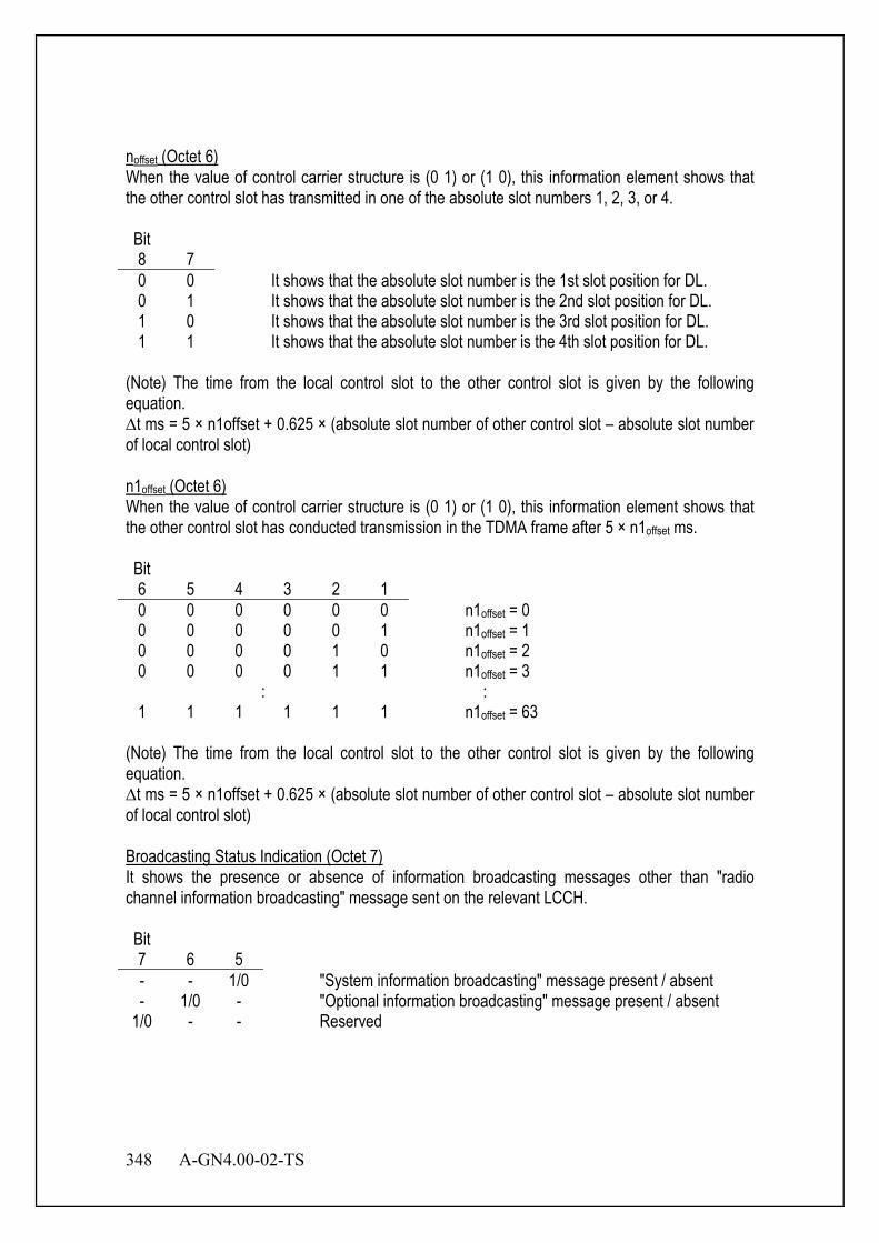
348 A-GN4.00-02-TS
noffset (Octet 6) When the value of control carrier structure is (0 1) or (1 0), this information element shows that the other control slot has transmitted in one of the absolute slot numbers 1, 2, 3, or 4. Bit 8 7
0 0 It shows that the absolute slot number is the 1st slot position for DL. 0 1 It shows that the absolute slot number is the 2nd slot position for DL. 1 0 It shows that the absolute slot number is the 3rd slot position for DL. 1 1 It shows that the absolute slot number is the 4th slot position for DL.
(Note) The time from the local control slot to the other control slot is given by the following equation. ∆t ms = 5 × n1offset + 0.625 × (absolute slot number of other control slot – absolute slot number of local control slot) n1offset (Octet 6) When the value of control carrier structure is (0 1) or (1 0), this information element shows that the other control slot has conducted transmission in the TDMA frame after 5 × n1offset ms. Bit 6 5 4 3 2 1
0 0 0 0 0 0 n1offset = 0 0 0 0 0 0 1 n1offset = 1 0 0 0 0 1 0 n1offset = 2 0 0 0 0 1 1 n1offset = 3
: : 1 1 1 1 1 1 n1offset = 63
(Note) The time from the local control slot to the other control slot is given by the following equation. ∆t ms = 5 × n1offset + 0.625 × (absolute slot number of other control slot – absolute slot number of local control slot) Broadcasting Status Indication (Octet 7) It shows the presence or absence of information broadcasting messages other than "radio channel information broadcasting" message sent on the relevant LCCH. Bit 7 6 5
- - 1/0 "System information broadcasting" message present / absent - 1/0 - "Optional information broadcasting" message present / absent
1/0 - - Reserved
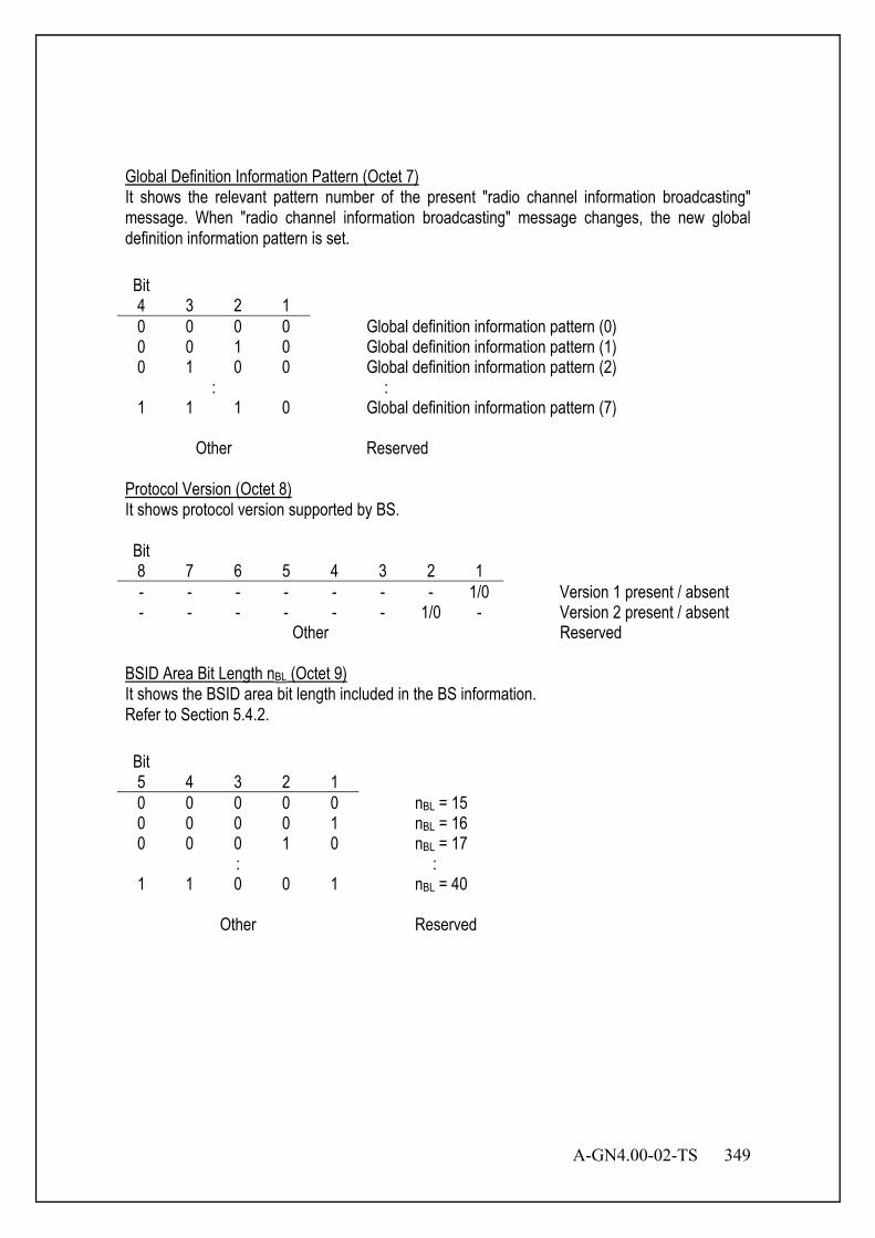
A-GN4.00-02-TS 349
Global Definition Information Pattern (Octet 7) It shows the relevant pattern number of the present "radio channel information broadcasting" message. When "radio channel information broadcasting" message changes, the new global definition information pattern is set. Bit 4 3 2 1
0 0 0 0 Global definition information pattern (0) 0 0 1 0 Global definition information pattern (1) 0 1 0 0 Global definition information pattern (2)
: : 1 1 1 0 Global definition information pattern (7)
Other Reserved
Protocol Version (Octet 8) It shows protocol version supported by BS. Bit 8 7 6 5 4 3 2 1
- - - - - - - 1/0 Version 1 present / absent - - - - - - 1/0 - Version 2 present / absent
Other Reserved BSID Area Bit Length nBL (Octet 9) It shows the BSID area bit length included in the BS information. Refer to Section 5.4.2. Bit 5 4 3 2 1
0 0 0 0 0 nBL = 15 0 0 0 0 1 nBL = 16 0 0 0 1 0 nBL = 17
: : 1 1 0 0 1 nBL = 40
Other Reserved
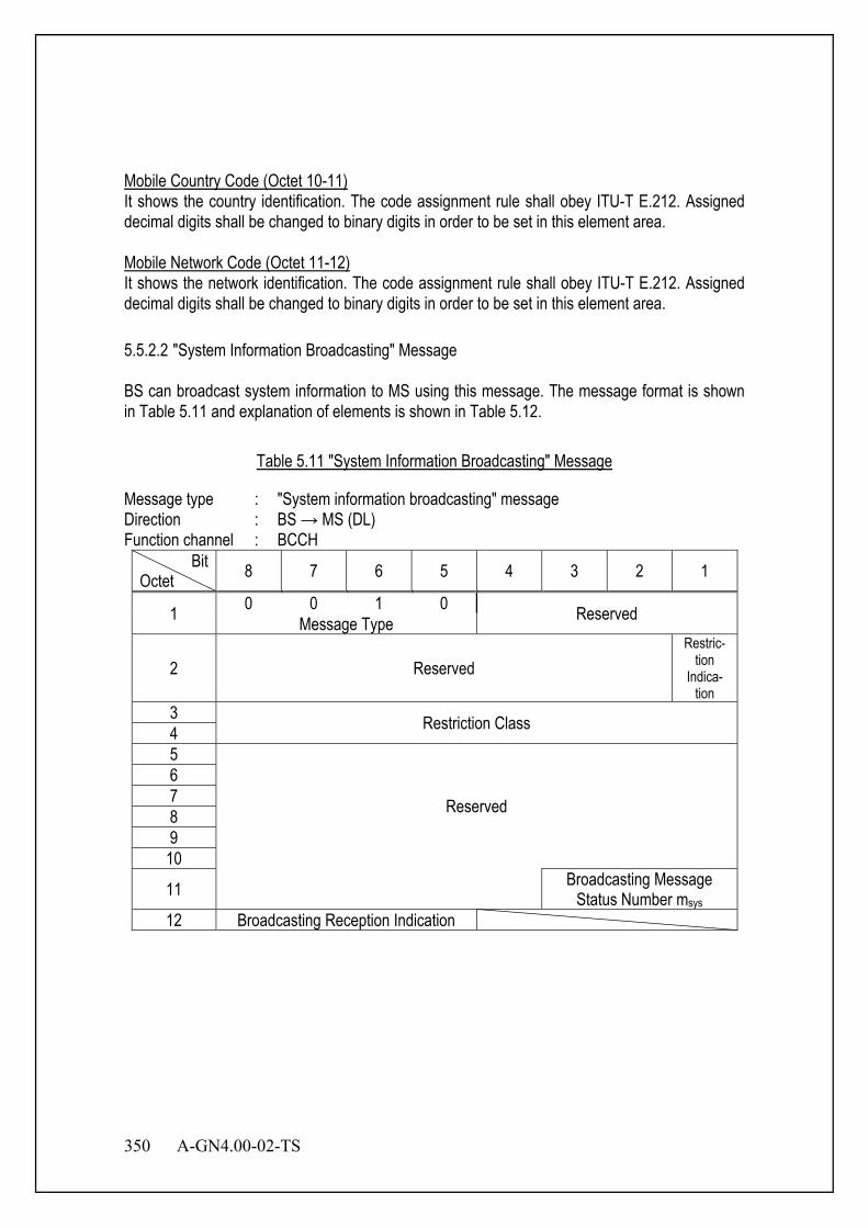
350 A-GN4.00-02-TS
Mobile Country Code (Octet 10-11) It shows the country identification. The code assignment rule shall obey ITU-T E.212. Assigned decimal digits shall be changed to binary digits in order to be set in this element area. Mobile Network Code (Octet 11-12) It shows the network identification. The code assignment rule shall obey ITU-T E.212. Assigned decimal digits shall be changed to binary digits in order to be set in this element area. 5.5.2.2 "System Information Broadcasting" Message BS can broadcast system information to MS using this message. The message format is shown in Table 5.11 and explanation of elements is shown in Table 5.12.
Table 5.11 "System Information Broadcasting" Message
Message type : "System information broadcasting" message Direction : BS → MS (DL) Function channel : BCCH
Bit Octet 8 7 6 5 4 3 2 1
1 0 0 1 0 Reserved Message Type
2 Reserved Restric-
tion Indica-
tion 3 Restriction Class 4 5
Reserved
6 7 8 9 10
11 Broadcasting Message Status Number msys
12 Broadcasting Reception Indication
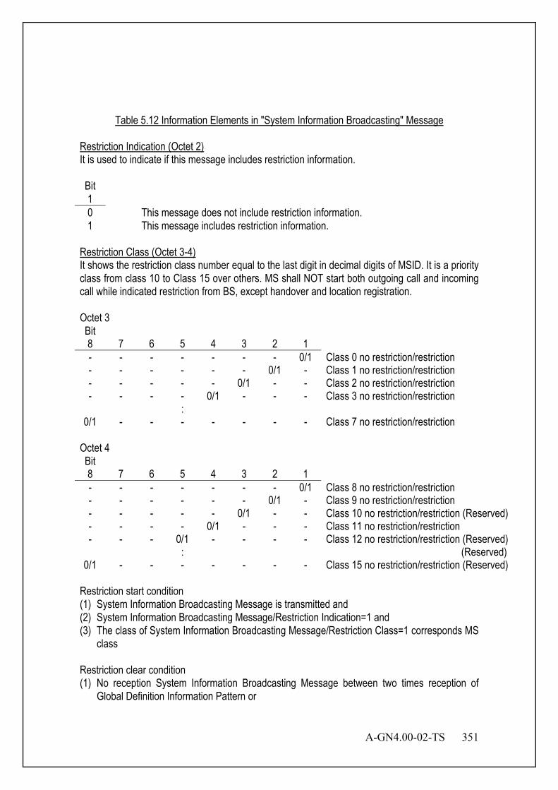
A-GN4.00-02-TS 351
Table 5.12 Information Elements in "System Information Broadcasting" Message
Restriction Indication (Octet 2) It is used to indicate if this message includes restriction information. Bit 1 0 This message does not include restriction information. 1 This message includes restriction information.
Restriction Class (Octet 3-4) It shows the restriction class number equal to the last digit in decimal digits of MSID. It is a priority class from class 10 to Class 15 over others. MS shall NOT start both outgoing call and incoming call while indicated restriction from BS, except handover and location registration. Octet 3 Bit 8 7 6 5 4 3 2 1
- - - - - - - 0/1 Class 0 no restriction/restriction - - - - - - 0/1 - Class 1 no restriction/restriction - - - - - 0/1 - - Class 2 no restriction/restriction - - - - 0/1 - - - Class 3 no restriction/restriction :
0/1 - - - - - - - Class 7 no restriction/restriction Octet 4 Bit 8 7 6 5 4 3 2 1
- - - - - - - 0/1 Class 8 no restriction/restriction - - - - - - 0/1 - Class 9 no restriction/restriction - - - - - 0/1 - - Class 10 no restriction/restriction (Reserved) - - - - 0/1 - - - Class 11 no restriction/restriction - - - 0/1 - - - - Class 12 no restriction/restriction (Reserved) : (Reserved)
0/1 - - - - - - - Class 15 no restriction/restriction (Reserved) Restriction start condition (1) System Information Broadcasting Message is transmitted and (2) System Information Broadcasting Message/Restriction Indication=1 and (3) The class of System Information Broadcasting Message/Restriction Class=1 corresponds MS
class Restriction clear condition (1) No reception System Information Broadcasting Message between two times reception of
Global Definition Information Pattern or
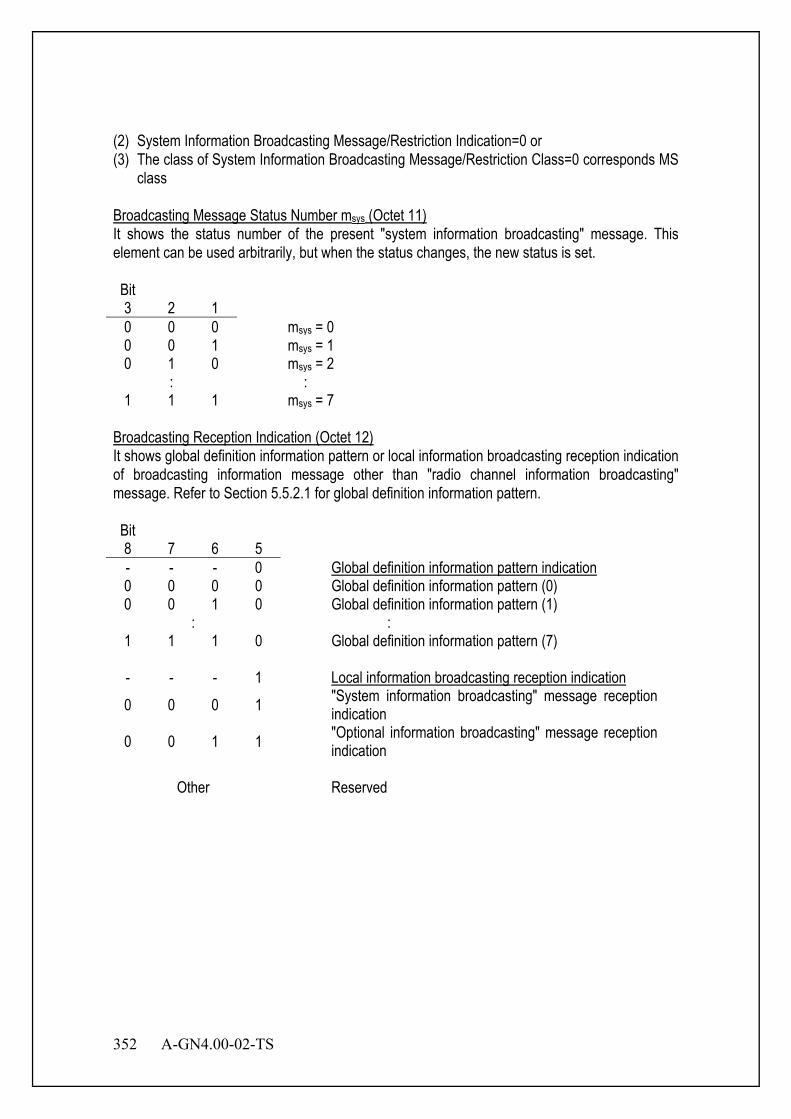
352 A-GN4.00-02-TS
(2) System Information Broadcasting Message/Restriction Indication=0 or (3) The class of System Information Broadcasting Message/Restriction Class=0 corresponds MS
class Broadcasting Message Status Number msys (Octet 11) It shows the status number of the present "system information broadcasting" message. This element can be used arbitrarily, but when the status changes, the new status is set. Bit 3 2 1
0 0 0 msys = 0 0 0 1 msys = 1 0 1 0 msys = 2
: : 1 1 1 msys = 7
Broadcasting Reception Indication (Octet 12) It shows global definition information pattern or local information broadcasting reception indication of broadcasting information message other than "radio channel information broadcasting" message. Refer to Section 5.5.2.1 for global definition information pattern. Bit 8 7 6 5
- - - 0 Global definition information pattern indication 0 0 0 0 Global definition information pattern (0) 0 0 1 0 Global definition information pattern (1)
: : 1 1 1 0 Global definition information pattern (7) - - - 1 Local information broadcasting reception indication 0 0 0 1 "System information broadcasting" message reception
indication 0 0 1 1 "Optional information broadcasting" message reception
indication
Other Reserved
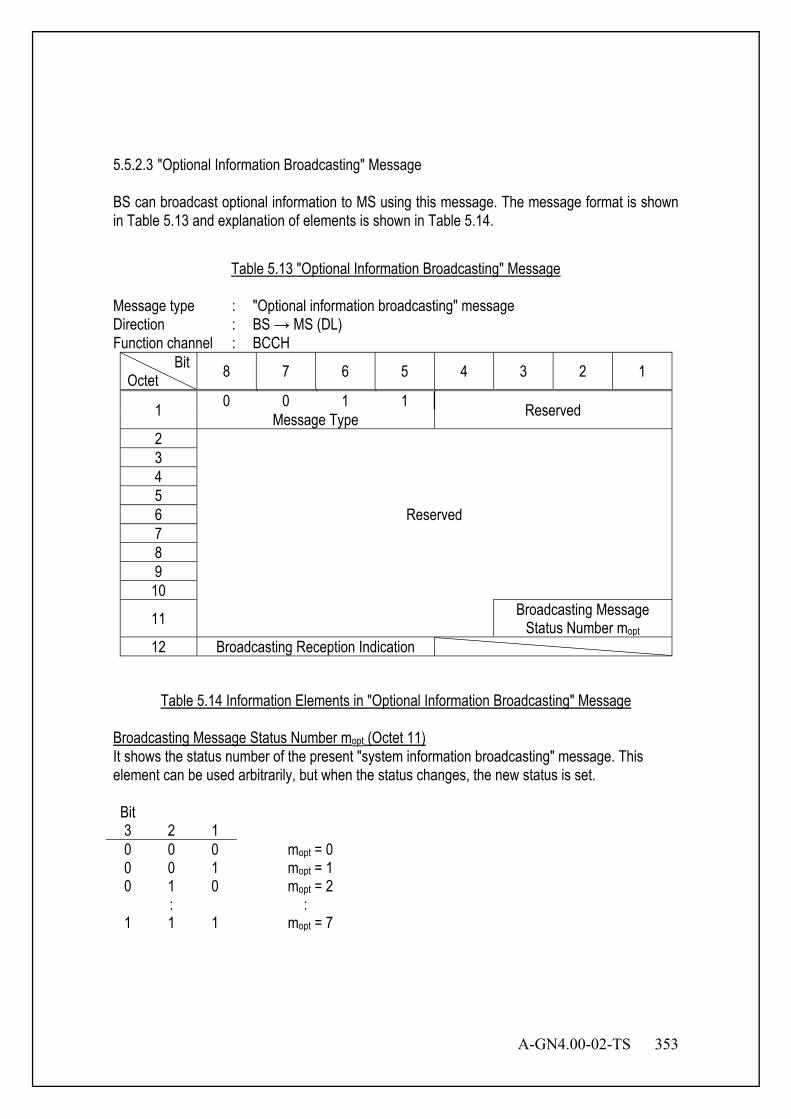
A-GN4.00-02-TS 353
5.5.2.3 "Optional Information Broadcasting" Message BS can broadcast optional information to MS using this message. The message format is shown in Table 5.13 and explanation of elements is shown in Table 5.14.
Table 5.13 "Optional Information Broadcasting" Message
Message type : "Optional information broadcasting" message Direction : BS → MS (DL) Function channel : BCCH
Bit Octet 8 7 6 5 4 3 2 1
1 0 0 1 1 Reserved Message Type 2
Reserved
3 4 5 6 7 8 9 10
11 Broadcasting Message Status Number mopt
12 Broadcasting Reception Indication
Table 5.14 Information Elements in "Optional Information Broadcasting" Message
Broadcasting Message Status Number mopt (Octet 11) It shows the status number of the present "system information broadcasting" message. This element can be used arbitrarily, but when the status changes, the new status is set. Bit 3 2 1
0 0 0 mopt = 0 0 0 1 mopt = 1 0 1 0 mopt = 2
: : 1 1 1 mopt = 7

354 A-GN4.00-02-TS
Broadcasting Reception Indication (Octet 12) It shows global definition information pattern or local information broadcasting reception indication of broadcasting information message other than "radio channel information broadcasting" message. Refer to Section 5.5.2.1 for global definition information pattern. Bit 8 7 6 5
- - - 0 Global definition information pattern indication 0 0 0 0 Global definition information pattern (0) 0 0 1 0 Global definition information pattern (1)
: : 1 1 1 0 Global definition information pattern (7) - - - 1 Local information broadcasting reception indication 0 0 0 1 "System information broadcasting" message reception
indication 0 0 1 1 "Optional information broadcasting" message reception
indication Other Reserved
5.5.3 MSG (Optional BCCH) 5.5.3.1 MSG (BCCH)
System information is divided into the MasterInformationBroadcastingBlock (MIBB) and a number of SystemInformationBroadcastingBlocks (SIBBs); The mapping of SIBBs to SI messages is flexibly configurable by schedulingInformation; The BS may schedule ADSCH transmissions concerning function channels other than BCCH in the same slot as used for BCCH. The minimum MS capability restricts the BCCH mapped to ADSCH e.g. regarding the maximum rate. System information validity and notification of changes: Change of system information only occurs at specific radio frames, i.e. the concept of a modification period is used. System information may be transmitted a number of times with the same content within a modification period, as defined by its scheduling. The modification period boundaries are defined by SFN values for which SFN mod m= 0, where m is the number of radio frames comprising the modification period. The modification period is configured by system information. When the network changes (some of the) system information, it first notifies the MSs about this change, i.e. this may be done throughout a modification period. In the next modification period,
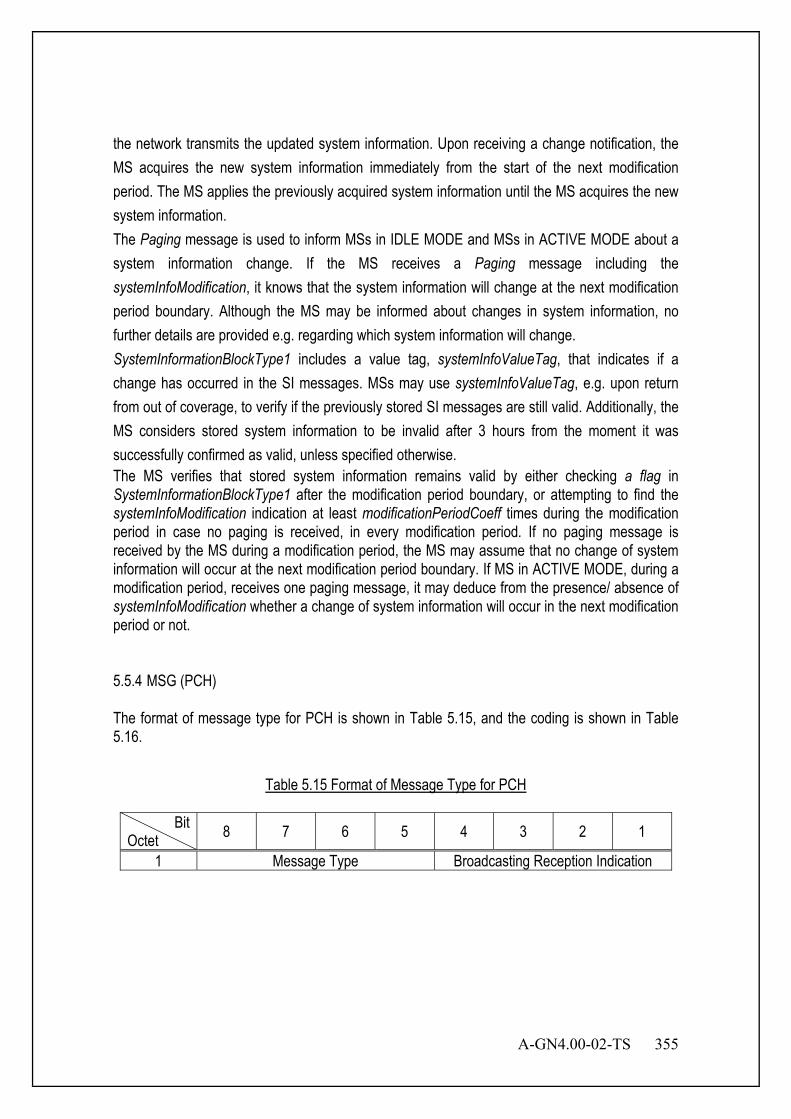
A-GN4.00-02-TS 355
the network transmits the updated system information. Upon receiving a change notification, the MS acquires the new system information immediately from the start of the next modification period. The MS applies the previously acquired system information until the MS acquires the new system information. The Paging message is used to inform MSs in IDLE MODE and MSs in ACTIVE MODE about a system information change. If the MS receives a Paging message including the systemInfoModification, it knows that the system information will change at the next modification period boundary. Although the MS may be informed about changes in system information, no further details are provided e.g. regarding which system information will change. SystemInformationBlockType1 includes a value tag, systemInfoValueTag, that indicates if a change has occurred in the SI messages. MSs may use systemInfoValueTag, e.g. upon return from out of coverage, to verify if the previously stored SI messages are still valid. Additionally, the MS considers stored system information to be invalid after 3 hours from the moment it was successfully confirmed as valid, unless specified otherwise. The MS verifies that stored system information remains valid by either checking a flag in SystemInformationBlockType1 after the modification period boundary, or attempting to find the systemInfoModification indication at least modificationPeriodCoeff times during the modification period in case no paging is received, in every modification period. If no paging message is received by the MS during a modification period, the MS may assume that no change of system information will occur at the next modification period boundary. If MS in ACTIVE MODE, during a modification period, receives one paging message, it may deduce from the presence/ absence of systemInfoModification whether a change of system information will occur in the next modification period or not. 5.5.4 MSG (PCH) The format of message type for PCH is shown in Table 5.15, and the coding is shown in Table 5.16.
Table 5.15 Format of Message Type for PCH
Bit Octet 8 7 6 5 4 3 2 1
1 Message Type Broadcasting Reception Indication
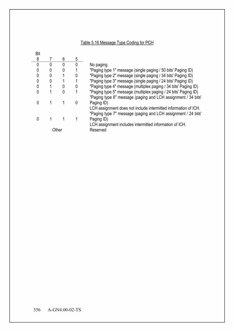
356 A-GN4.00-02-TS
Table 5.16 Message Type Coding for PCH
Bit 8 7 6 5
0 0 0 0 No paging 0 0 0 1 "Paging type 1" message (single paging / 50 bits' Paging ID) 0 0 1 0 "Paging type 2" message (single paging / 34 bits' Paging ID) 0 0 1 1 "Paging type 3" message (single paging / 24 bits' Paging ID) 0 1 0 0 "Paging type 4" message (multiplex paging / 34 bits' Paging ID) 0 1 0 1 "Paging type 5" message (multiplex paging / 24 bits' Paging ID)
0 1 1 0 "Paging type 6" message (paging and LCH assignment / 34 bits' Paging ID) LCH assignment does not include intermitted information of ICH.
0 1 1 1 "Paging type 7" message (paging and LCH assignment / 24 bits' Paging ID) LCH assignment includes intermitted information of ICH.
Other Reserved

A-GN4.00-02-TS 357
5.5.4.1 “No Paging” Message Using this message, BS can notify MS of no paging in this PCH. The message format is shown in Table 5.17, and the explanation of information elements is shown in Table 5.18.
Table 5.17 "No Paging" Message
Message type : "No Paging" message Direction : BS → MS (DL) Function channel : PCH
Bit Octet 8 7 6 5 4 3 2 1
1 0 0 0 0 Broadcasting Reception Indication Message Type 2
Reserved
3 4 5 6 7 8 9 10 11
12 Broadcasting Message Status Number mi
Table 5.18 Information Elements in "No Paging" Message
Broadcasting Reception Indication (Octet 1) It shows global definition information pattern or local information broadcasting reception indication of broadcasting information message other than “radio channel information broadcasting” message. Refer to Section 5.5.2.1 for global definition information pattern.
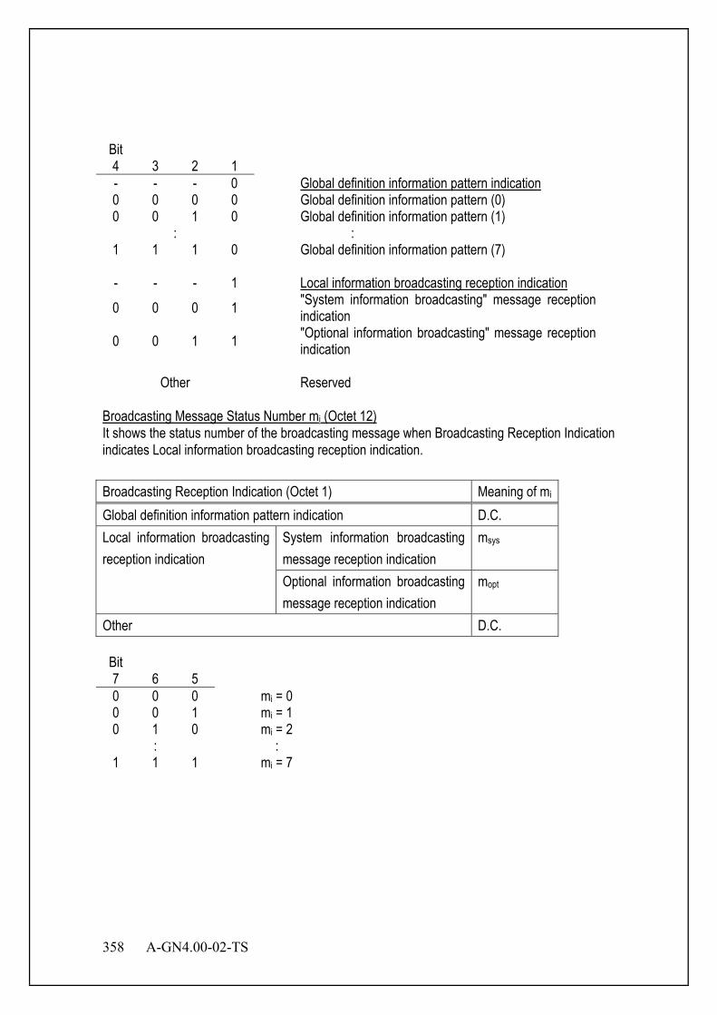
358 A-GN4.00-02-TS
Bit 4 3 2 1
- - - 0 Global definition information pattern indication 0 0 0 0 Global definition information pattern (0) 0 0 1 0 Global definition information pattern (1)
: : 1 1 1 0 Global definition information pattern (7) - - - 1 Local information broadcasting reception indication 0 0 0 1 "System information broadcasting" message reception
indication 0 0 1 1 "Optional information broadcasting" message reception
indication
Other Reserved Broadcasting Message Status Number mi (Octet 12) It shows the status number of the broadcasting message when Broadcasting Reception Indication indicates Local information broadcasting reception indication. Broadcasting Reception Indication (Octet 1) Meaning of mi Global definition information pattern indication D.C. Local information broadcasting reception indication
System information broadcasting message reception indication
msys
Optional information broadcasting message reception indication
mopt
Other D.C. Bit 7 6 5
0 0 0 mi = 0 0 0 1 mi = 1 0 1 0 mi = 2
: : 1 1 1 mi = 7
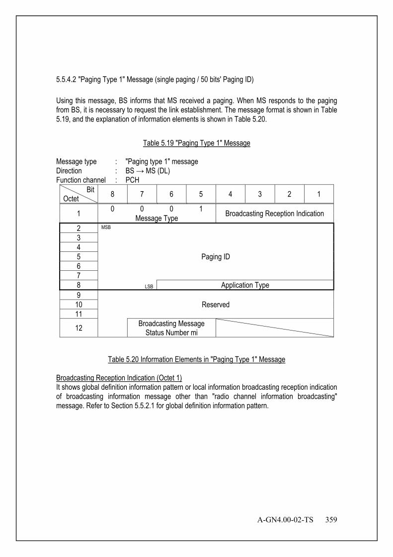
A-GN4.00-02-TS 359
5.5.4.2 "Paging Type 1" Message (single paging / 50 bits' Paging ID) Using this message, BS informs that MS received a paging. When MS responds to the paging from BS, it is necessary to request the link establishment. The message format is shown in Table 5.19, and the explanation of information elements is shown in Table 5.20.
Table 5.19 "Paging Type 1" Message
Message type : "Paging type 1" message Direction : BS → MS (DL) Function channel : PCH
Bit Octet 8 7 6 5 4 3 2 1
1 0 0 0 1 Broadcasting Reception Indication Message Type 2 MSB
3
Paging ID 4 5 6 7 8 LSB Application Type 9
Reserved 10 11
12 Broadcasting Message Status Number mi
Table 5.20 Information Elements in "Paging Type 1" Message
Broadcasting Reception Indication (Octet 1) It shows global definition information pattern or local information broadcasting reception indication of broadcasting information message other than "radio channel information broadcasting" message. Refer to Section 5.5.2.1 for global definition information pattern.

360 A-GN4.00-02-TS
Bit 4 3 2 1
- - - 0 Global definition information pattern indication 0 0 0 0 Global definition information pattern (0) 0 0 1 0 Global definition information pattern (1)
: : 1 1 1 0 Global definition information pattern (7) - - - 1 Local information broadcasting reception indication 0 0 0 1 "System information broadcasting" message reception
indication 0 0 1 1 "Optional information broadcasting" message reception
indication
Other Reserved Paging ID (Octet 2 - 8) Paging ID is specified as a 50 bits' number, and ID for identifying MS on the paging message. However, MSID can be allocated when Paging ID is a 34 bits' number. Application Type (Octet 8) It indicates application type. Bit 6 5 4 3 2 1
0 0 0 0 0 0 Restoration from sleep state 0 0 0 0 0 1 Voice 0 0 0 0 1 0 Unrestricted digital information
Other Reserved Broadcasting Message Status Number mi (Octet 12) It shows the status number of the broadcasting message when Broadcasting Reception Indication indicates Local information broadcasting reception indication. Broadcasting Reception Indication (Octet 1) Meaning of mi Global definition information pattern indication D.C. Local information broadcasting reception indication
System information broadcasting message reception indication
msys
Optional information broadcasting message reception indication
mopt
Other D.C.
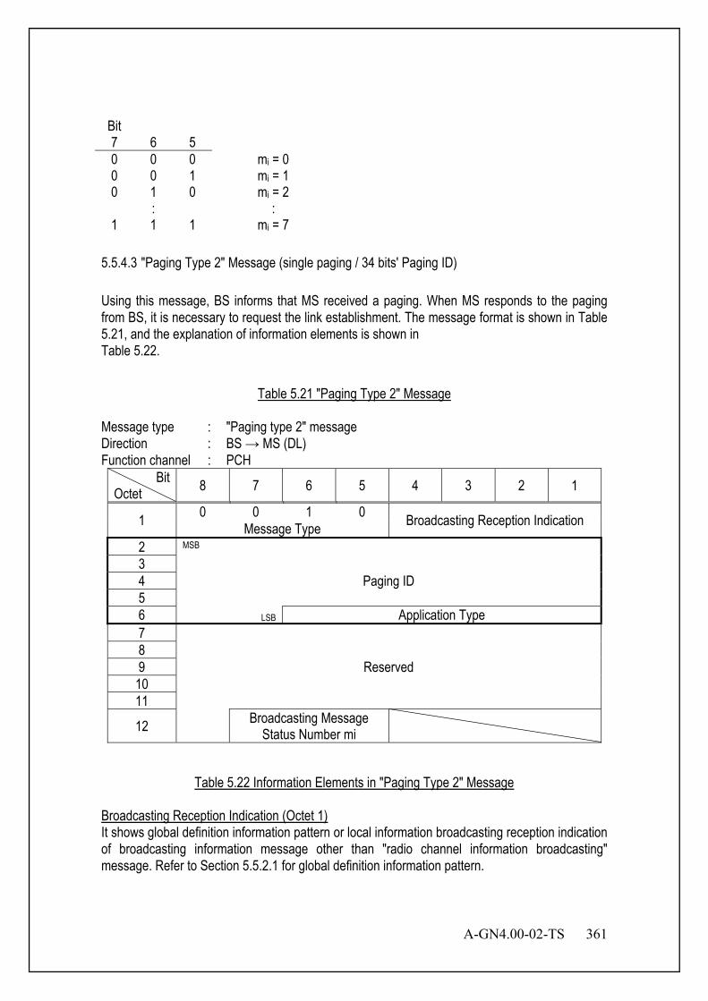
A-GN4.00-02-TS 361
Bit 7 6 5
0 0 0 mi = 0 0 0 1 mi = 1 0 1 0 mi = 2
: : 1 1 1 mi = 7
5.5.4.3 "Paging Type 2" Message (single paging / 34 bits' Paging ID) Using this message, BS informs that MS received a paging. When MS responds to the paging from BS, it is necessary to request the link establishment. The message format is shown in Table 5.21, and the explanation of information elements is shown in Table 5.22.
Table 5.21 "Paging Type 2" Message
Message type : "Paging type 2" message Direction : BS → MS (DL) Function channel : PCH
Bit Octet 8 7 6 5 4 3 2 1
1 0 0 1 0 Broadcasting Reception Indication Message Type 2 MSB
3 Paging ID 4
5 6 LSB Application Type 7
Reserved 8 9 10 11
12 Broadcasting Message Status Number mi
Table 5.22 Information Elements in "Paging Type 2" Message
Broadcasting Reception Indication (Octet 1) It shows global definition information pattern or local information broadcasting reception indication of broadcasting information message other than "radio channel information broadcasting" message. Refer to Section 5.5.2.1 for global definition information pattern.
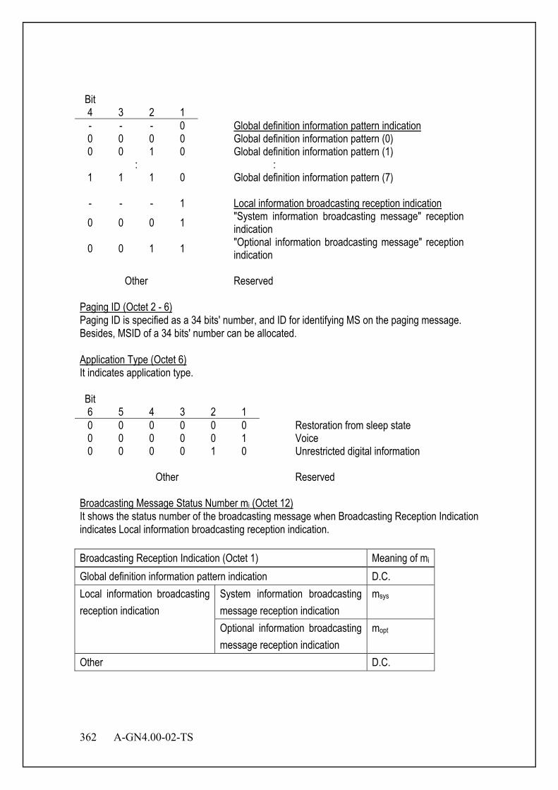
362 A-GN4.00-02-TS
Bit 4 3 2 1
- - - 0 Global definition information pattern indication 0 0 0 0 Global definition information pattern (0) 0 0 1 0 Global definition information pattern (1)
: : 1 1 1 0 Global definition information pattern (7) - - - 1 Local information broadcasting reception indication 0 0 0 1 "System information broadcasting message" reception
indication 0 0 1 1 "Optional information broadcasting message" reception
indication
Other Reserved Paging ID (Octet 2 - 6) Paging ID is specified as a 34 bits' number, and ID for identifying MS on the paging message. Besides, MSID of a 34 bits' number can be allocated. Application Type (Octet 6) It indicates application type. Bit 6 5 4 3 2 1
0 0 0 0 0 0 Restoration from sleep state 0 0 0 0 0 1 Voice 0 0 0 0 1 0 Unrestricted digital information
Other Reserved Broadcasting Message Status Number mi (Octet 12) It shows the status number of the broadcasting message when Broadcasting Reception Indication indicates Local information broadcasting reception indication. Broadcasting Reception Indication (Octet 1) Meaning of mi Global definition information pattern indication D.C. Local information broadcasting reception indication
System information broadcasting message reception indication
msys
Optional information broadcasting message reception indication
mopt
Other D.C.
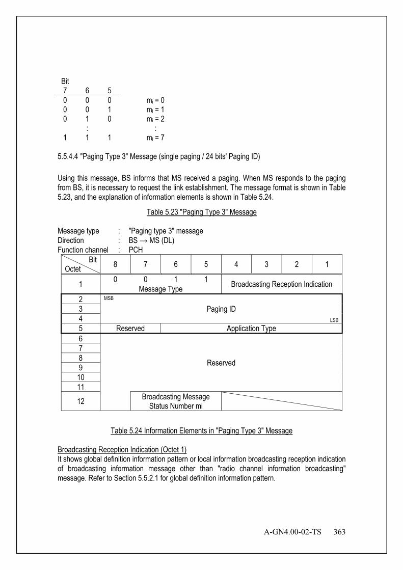
A-GN4.00-02-TS 363
Bit 7 6 5
0 0 0 mi = 0 0 0 1 mi = 1 0 1 0 mi = 2
: : 1 1 1 mi = 7
5.5.4.4 "Paging Type 3" Message (single paging / 24 bits' Paging ID) Using this message, BS informs that MS received a paging. When MS responds to the paging from BS, it is necessary to request the link establishment. The message format is shown in Table 5.23, and the explanation of information elements is shown in Table 5.24.
Table 5.23 "Paging Type 3" Message
Message type : "Paging type 3" message Direction : BS → MS (DL) Function channel : PCH
Bit Octet 8 7 6 5 4 3 2 1
1 0 0 1 1 Broadcasting Reception Indication Message Type 2 MSB
3 Paging ID 4 LSB 5 Reserved Application Type 6
Reserved
7 8 9 10 11
12 Broadcasting Message Status Number mi
Table 5.24 Information Elements in "Paging Type 3" Message
Broadcasting Reception Indication (Octet 1) It shows global definition information pattern or local information broadcasting reception indication of broadcasting information message other than "radio channel information broadcasting" message. Refer to Section 5.5.2.1 for global definition information pattern.

364 A-GN4.00-02-TS
Bit 4 3 2 1
- - - 0 Global definition information pattern indication 0 0 0 0 Global definition information pattern (0) 0 0 1 0 Global definition information pattern (1)
: : 1 1 1 0 Global definition information pattern (7) - - - 1 Local information broadcasting reception indication 0 0 0 1 "System information broadcasting" message reception
indication 0 0 1 1 "Optional information broadcasting" message reception
indication
Other Reserved Paging ID (Octet 2 - 4) Paging ID is specified as a 24 bits' number, and ID for identifying MS on the paging message. However, MSID can be allocated when Paging ID is a 34 bits' number. Application Type (Octet 5) It indicates application type. Bit 6 5 4 3 2 1
0 0 0 0 0 0 Restoration from sleep state 0 0 0 0 0 1 Voice 0 0 0 0 1 0 Unrestricted digital information
Other Reserved Broadcasting Message Status Number mi (Octet 12) It shows the status number of the broadcasting message when Broadcasting Reception Indication indicates Local information broadcasting reception indication. Broadcasting Reception Indication (Octet 1) Meaning of mi Global definition information pattern indication D.C. Local information broadcasting reception indication
System information broadcasting message reception indication
msys
Optional information broadcasting message reception indication
mopt
Other D.C.
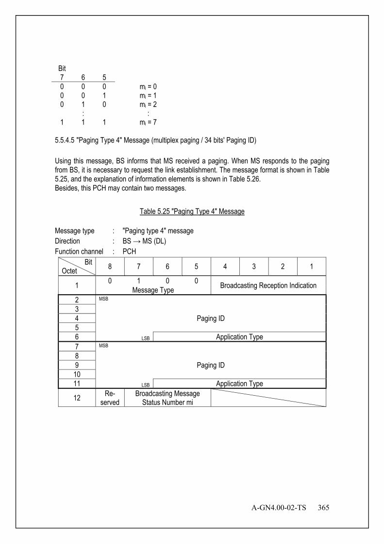
A-GN4.00-02-TS 365
Bit 7 6 5
0 0 0 mi = 0 0 0 1 mi = 1 0 1 0 mi = 2
: : 1 1 1 mi = 7
5.5.4.5 "Paging Type 4" Message (multiplex paging / 34 bits' Paging ID) Using this message, BS informs that MS received a paging. When MS responds to the paging from BS, it is necessary to request the link establishment. The message format is shown in Table 5.25, and the explanation of information elements is shown in Table 5.26. Besides, this PCH may contain two messages.
Table 5.25 "Paging Type 4" Message
Message type : "Paging type 4" message Direction : BS → MS (DL) Function channel : PCH
Bit Octet 8 7 6 5 4 3 2 1
1 0 1 0 0 Broadcasting Reception Indication Message Type 2 MSB
3 Paging ID 4
5 6 LSB Application Type 7 MSB
8 Paging ID 9
10 11 LSB Application Type
12 Re- served
Broadcasting Message Status Number mi

366 A-GN4.00-02-TS
Table 5.26 Information Elements in "Paging Type 4" Message
Broadcasting Reception Indication (Octet 1) It shows global definition information pattern or local information broadcasting reception indication of broadcasting information message other than "radio channel information broadcasting" message. Refer to Section 5.5.2.1 for global definition information pattern. Bit 4 3 2 1
- - - 0 Global definition information pattern indication 0 0 0 0 Global definition information pattern (0) 0 0 1 0 Global definition information pattern (1)
: : 1 1 1 0 Global definition information pattern (7) - - - 1 Local information broadcasting reception indication 0 0 0 1 "System information broadcasting" message reception
indication 0 0 1 1 "Optional information broadcasting" message reception
indication
Other Reserved Paging ID (Octet 2 - 6, 7 - 11) Paging ID is specified as a 34 bits' number, and ID for identifying MS on the paging message. Besides, MSID of 34 bits' number can be allocated. Application Type (Octet 6, 11) It indicates application type. Bit 6 5 4 3 2 1
0 0 0 0 0 0 Restoration from sleep state 0 0 0 0 0 1 Voice 0 0 0 0 1 0 Unrestricted digital information
Other Reserved
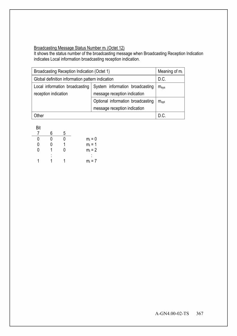
A-GN4.00-02-TS 367
Broadcasting Message Status Number mi (Octet 12) It shows the status number of the broadcasting message when Broadcasting Reception Indication indicates Local information broadcasting reception indication. Broadcasting Reception Indication (Octet 1) Meaning of mi Global definition information pattern indication D.C. Local information broadcasting reception indication
System information broadcasting message reception indication
msys
Optional information broadcasting message reception indication
mopt
Other D.C. Bit 7 6 5
0 0 0 mi = 0 0 0 1 mi = 1 0 1 0 mi = 2
: : 1 1 1 mi = 7
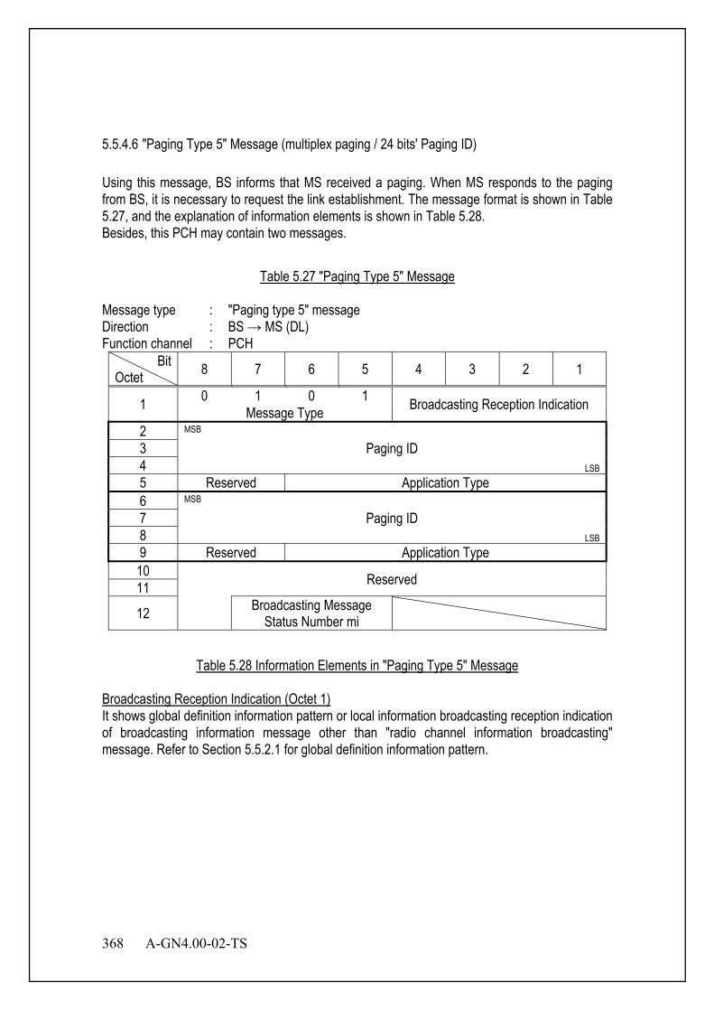
368 A-GN4.00-02-TS
5.5.4.6 "Paging Type 5" Message (multiplex paging / 24 bits' Paging ID) Using this message, BS informs that MS received a paging. When MS responds to the paging from BS, it is necessary to request the link establishment. The message format is shown in Table 5.27, and the explanation of information elements is shown in Table 5.28. Besides, this PCH may contain two messages.
Table 5.27 "Paging Type 5" Message
Message type : "Paging type 5" message Direction : BS → MS (DL) Function channel : PCH
Bit Octet 8 7 6 5 4 3 2 1
1 0 1 0 1 Broadcasting Reception Indication Message Type 2 MSB
3 Paging ID 4 LSB 5 Reserved Application Type 6 MSB
7 Paging ID 8 LSB 9 Reserved Application Type 10 Reserved 11
12 Broadcasting Message Status Number mi
Table 5.28 Information Elements in "Paging Type 5" Message
Broadcasting Reception Indication (Octet 1) It shows global definition information pattern or local information broadcasting reception indication of broadcasting information message other than "radio channel information broadcasting" message. Refer to Section 5.5.2.1 for global definition information pattern.
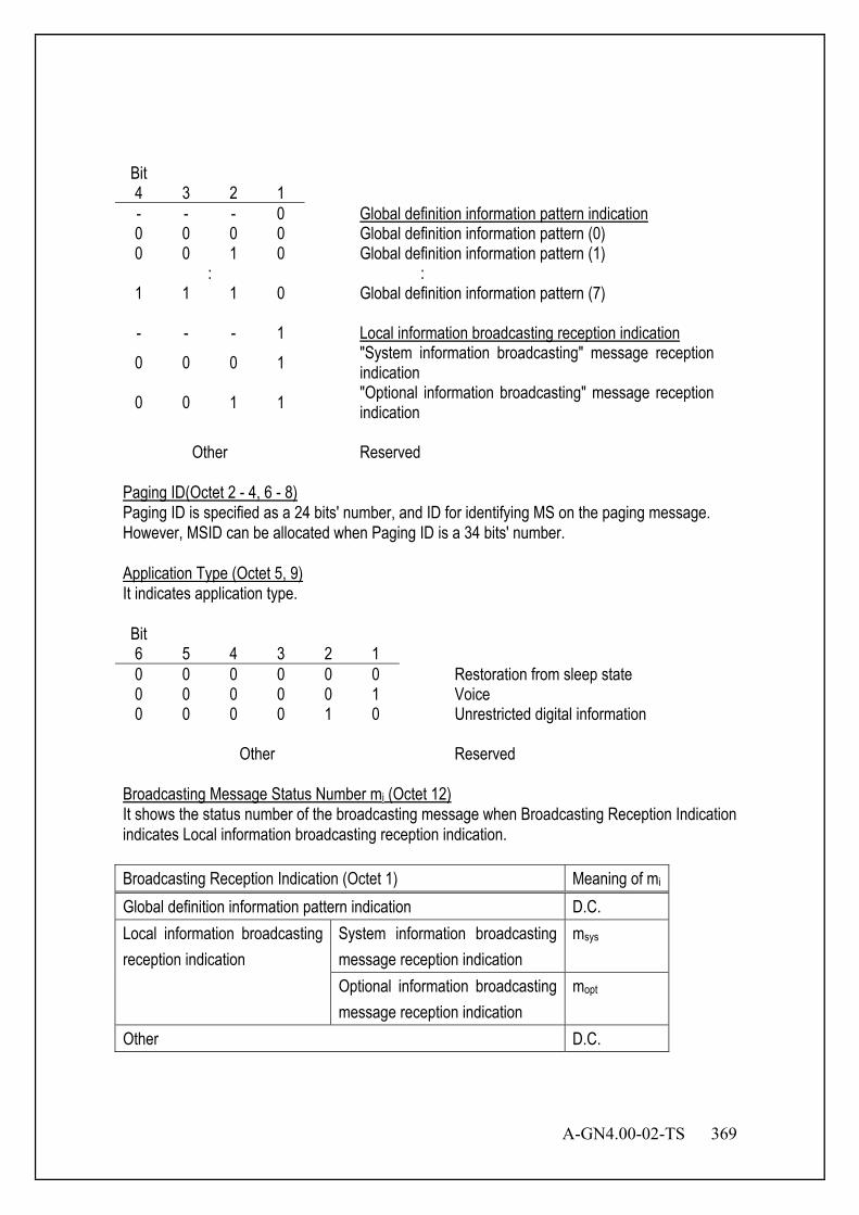
A-GN4.00-02-TS 369
Bit 4 3 2 1
- - - 0 Global definition information pattern indication 0 0 0 0 Global definition information pattern (0) 0 0 1 0 Global definition information pattern (1)
: : 1 1 1 0 Global definition information pattern (7) - - - 1 Local information broadcasting reception indication 0 0 0 1 "System information broadcasting" message reception
indication 0 0 1 1 "Optional information broadcasting" message reception
indication
Other Reserved Paging ID(Octet 2 - 4, 6 - 8) Paging ID is specified as a 24 bits' number, and ID for identifying MS on the paging message. However, MSID can be allocated when Paging ID is a 34 bits' number. Application Type (Octet 5, 9) It indicates application type. Bit 6 5 4 3 2 1
0 0 0 0 0 0 Restoration from sleep state 0 0 0 0 0 1 Voice 0 0 0 0 1 0 Unrestricted digital information
Other Reserved Broadcasting Message Status Number mi (Octet 12) It shows the status number of the broadcasting message when Broadcasting Reception Indication indicates Local information broadcasting reception indication. Broadcasting Reception Indication (Octet 1) Meaning of mi Global definition information pattern indication D.C. Local information broadcasting reception indication
System information broadcasting message reception indication
msys
Optional information broadcasting message reception indication
mopt
Other D.C.
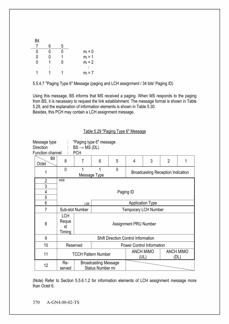
370 A-GN4.00-02-TS
Bit 7 6 5
0 0 0 mi = 0 0 0 1 mi = 1 0 1 0 mi = 2
: : 1 1 1 mi = 7
5.5.4.7 "Paging Type 6" Message (paging and LCH assignment / 34 bits' Paging ID) Using this message, BS informs that MS received a paging. When MS responds to the paging from BS, it is necessary to request the link establishment. The message format is shown in Table 5.29, and the explanation of information elements is shown in Table 5.30. Besides, this PCH may contain a LCH assignment message.
Table 5.29 "Paging Type 6" Message
Message type : "Paging type 6" message Direction : BS → MS (DL) Function channel : PCH
Bit Octet 8 7 6 5 4 3 2 1
1 0 1 1 0 Broadcasting Reception Indication Message Type 2 MSB
3 Paging ID 4
5 6 LSB Application Type 7 Sub-slot Number Temporary LCH Number
8 LCH
Request
Timing Assignment PRU Number
9 Shift Direction Control Information 10 Reserved Power Control Information
11 TCCH Pattern Number ANCH MIMO (UL)
ANCH MIMO (DL)
12 Re- served
Broadcasting Message Status Number mi
(Note) Refer to Section 5.5.6.1.2 for information elements of LCH assignment message more than Octet 6.
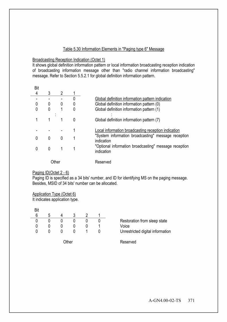
A-GN4.00-02-TS 371
Table 5.30 Information Elements in "Paging type 6" Message
Broadcasting Reception Indication (Octet 1) It shows global definition information pattern or local information broadcasting reception indication of broadcasting information message other than "radio channel information broadcasting" message. Refer to Section 5.5.2.1 for global definition information pattern. Bit 4 3 2 1
- - - 0 Global definition information pattern indication 0 0 0 0 Global definition information pattern (0) 0 0 1 0 Global definition information pattern (1)
: : 1 1 1 0 Global definition information pattern (7) - - - 1 Local information broadcasting reception indication 0 0 0 1 "System information broadcasting" message reception
indication 0 0 1 1 "Optional information broadcasting" message reception
indication
Other Reserved Paging ID(Octet 2 - 6) Paging ID is specified as a 34 bits' number, and ID for identifying MS on the paging message. Besides, MSID of 34 bits' number can be allocated. Application Type (Octet 6) It indicates application type. Bit 6 5 4 3 2 1
0 0 0 0 0 0 Restoration from sleep state 0 0 0 0 0 1 Voice 0 0 0 0 1 0 Unrestricted digital information
Other Reserved
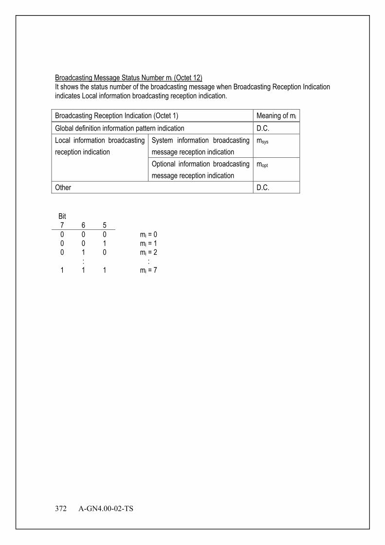
372 A-GN4.00-02-TS
Broadcasting Message Status Number mi (Octet 12) It shows the status number of the broadcasting message when Broadcasting Reception Indication indicates Local information broadcasting reception indication. Broadcasting Reception Indication (Octet 1) Meaning of mi Global definition information pattern indication D.C. Local information broadcasting reception indication
System information broadcasting message reception indication
msys
Optional information broadcasting message reception indication
mopt
Other D.C. Bit 7 6 5
0 0 0 mi = 0 0 0 1 mi = 1 0 1 0 mi = 2
: : 1 1 1 mi = 7
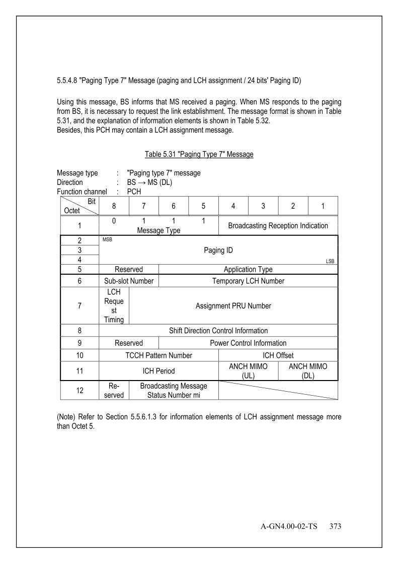
A-GN4.00-02-TS 373
5.5.4.8 "Paging Type 7" Message (paging and LCH assignment / 24 bits' Paging ID) Using this message, BS informs that MS received a paging. When MS responds to the paging from BS, it is necessary to request the link establishment. The message format is shown in Table 5.31, and the explanation of information elements is shown in Table 5.32. Besides, this PCH may contain a LCH assignment message.
Table 5.31 "Paging Type 7" Message
Message type : "Paging type 7" message Direction : BS → MS (DL) Function channel : PCH
Bit Octet 8 7 6 5 4 3 2 1
1 0 1 1 1 Broadcasting Reception Indication Message Type 2 MSB
3 Paging ID 4 LSB 5 Reserved Application Type 6 Sub-slot Number Temporary LCH Number
7 LCH
Request
Timing Assignment PRU Number
8 Shift Direction Control Information 9 Reserved Power Control Information 10 TCCH Pattern Number ICH Offset
11 ICH Period ANCH MIMO (UL)
ANCH MIMO (DL)
12 Re- served
Broadcasting Message Status Number mi
(Note) Refer to Section 5.5.6.1.3 for information elements of LCH assignment message more than Octet 5.
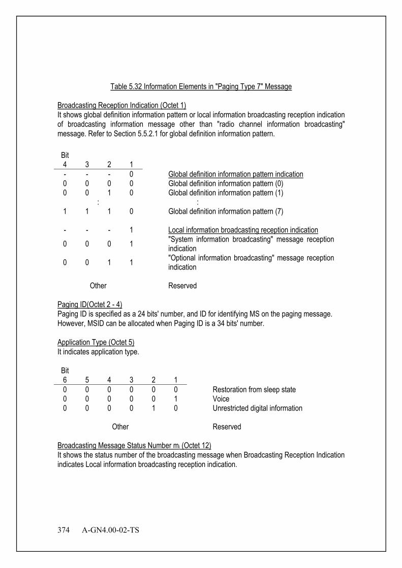
374 A-GN4.00-02-TS
Table 5.32 Information Elements in "Paging Type 7" Message
Broadcasting Reception Indication (Octet 1) It shows global definition information pattern or local information broadcasting reception indication of broadcasting information message other than "radio channel information broadcasting" message. Refer to Section 5.5.2.1 for global definition information pattern. Bit 4 3 2 1
- - - 0 Global definition information pattern indication 0 0 0 0 Global definition information pattern (0) 0 0 1 0 Global definition information pattern (1)
: : 1 1 1 0 Global definition information pattern (7) - - - 1 Local information broadcasting reception indication 0 0 0 1 "System information broadcasting" message reception
indication 0 0 1 1 "Optional information broadcasting" message reception
indication
Other Reserved Paging ID(Octet 2 - 4) Paging ID is specified as a 24 bits' number, and ID for identifying MS on the paging message. However, MSID can be allocated when Paging ID is a 34 bits' number. Application Type (Octet 5) It indicates application type. Bit 6 5 4 3 2 1
0 0 0 0 0 0 Restoration from sleep state 0 0 0 0 0 1 Voice 0 0 0 0 1 0 Unrestricted digital information
Other Reserved Broadcasting Message Status Number mi (Octet 12) It shows the status number of the broadcasting message when Broadcasting Reception Indication indicates Local information broadcasting reception indication.
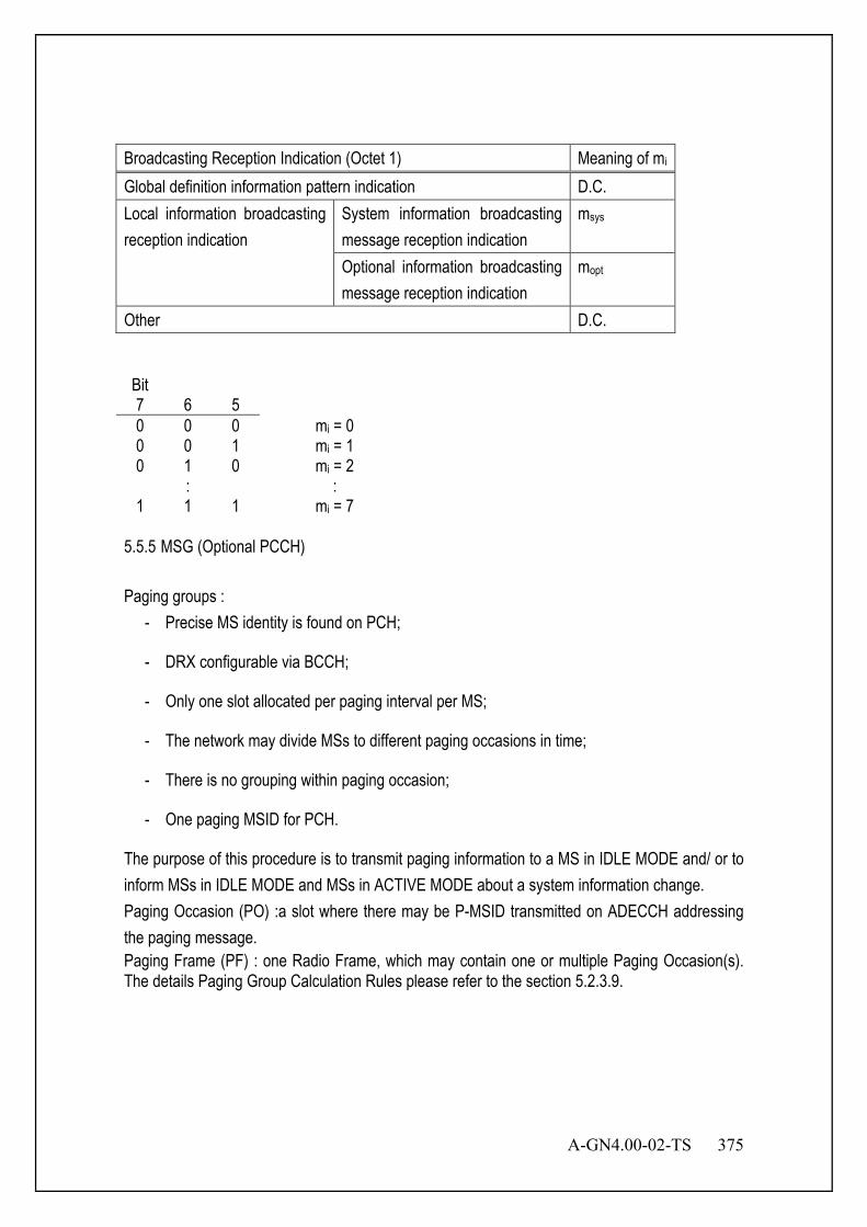
A-GN4.00-02-TS 375
Broadcasting Reception Indication (Octet 1) Meaning of mi Global definition information pattern indication D.C. Local information broadcasting reception indication
System information broadcasting message reception indication
msys
Optional information broadcasting message reception indication
mopt
Other D.C. Bit 7 6 5
0 0 0 mi = 0 0 0 1 mi = 1 0 1 0 mi = 2
: : 1 1 1 mi = 7
5.5.5 MSG (Optional PCCH) Paging groups :
- Precise MS identity is found on PCH;
- DRX configurable via BCCH;
- Only one slot allocated per paging interval per MS;
- The network may divide MSs to different paging occasions in time;
- There is no grouping within paging occasion;
- One paging MSID for PCH.
The purpose of this procedure is to transmit paging information to a MS in IDLE MODE and/ or to inform MSs in IDLE MODE and MSs in ACTIVE MODE about a system information change. Paging Occasion (PO) :a slot where there may be P-MSID transmitted on ADECCH addressing the paging message. Paging Frame (PF) : one Radio Frame, which may contain one or multiple Paging Occasion(s). The details Paging Group Calculation Rules please refer to the section 5.2.3.9.
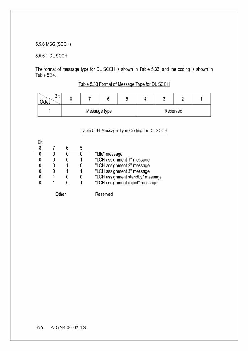
376 A-GN4.00-02-TS
5.5.6 MSG (SCCH) 5.5.6.1 DL SCCH The format of message type for DL SCCH is shown in Table 5.33, and the coding is shown in Table 5.34.
Table 5.33 Format of Message Type for DL SCCH
Bit Octet 8 7 6 5 4 3 2 1
1 Message type Reserved
Table 5.34 Message Type Coding for DL SCCH
Bit 8 7 6 5
0 0 0 0 "Idle" message 0 0 0 1 "LCH assignment 1" message 0 0 1 0 "LCH assignment 2" message 0 0 1 1 "LCH assignment 3" message 0 1 0 0 "LCH assignment standby" message 0 1 0 1 "LCH assignment reject" message
Other Reserved

A-GN4.00-02-TS 377
5.5.6.1.1 "Idle" Message This message can be transmitted only when there is no information to be transmitted in DL SCCH. The message format is shown in Table 5.35.
Table 5.35 "Idle" Message
Message type : "Idle" message Direction : BS → MS (DL) Function channel : SCCH
Bit Octet 8 7 6 5 4 3 2 1
1 0 0 0 0 Reserved Message Type 2
Reserved
3 4 5 6 7 8 9 10 11 12
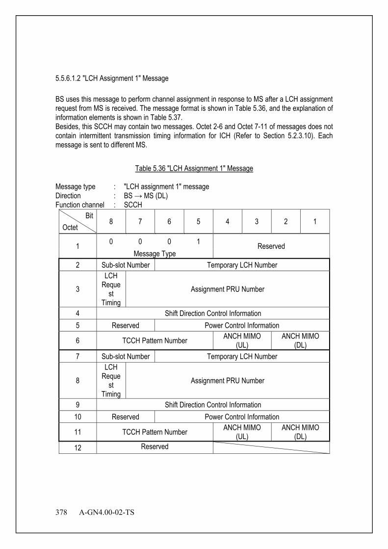
378 A-GN4.00-02-TS
5.5.6.1.2 "LCH Assignment 1" Message BS uses this message to perform channel assignment in response to MS after a LCH assignment request from MS is received. The message format is shown in Table 5.36, and the explanation of information elements is shown in Table 5.37. Besides, this SCCH may contain two messages. Octet 2-6 and Octet 7-11 of messages does not contain intermittent transmission timing information for ICH (Refer to Section 5.2.3.10). Each message is sent to different MS.
Table 5.36 "LCH Assignment 1" Message
Message type : "LCH assignment 1" message Direction : BS → MS (DL) Function channel : SCCH
Bit Octet
8 7 6 5 4 3 2 1
1 0 0 0 1 Reserved Message Type
2 Sub-slot Number Temporary LCH Number
3 LCH
Request
Timing Assignment PRU Number
4 Shift Direction Control Information 5 Reserved Power Control Information
6 TCCH Pattern Number ANCH MIMO (UL)
ANCH MIMO (DL)
7 Sub-slot Number Temporary LCH Number
8 LCH
Request
Timing Assignment PRU Number
9 Shift Direction Control Information 10 Reserved Power Control Information
11 TCCH Pattern Number ANCH MIMO (UL)
ANCH MIMO (DL)
12 Reserved

A-GN4.00-02-TS 379
Table 5.37 Information Elements in "LCH Assignment 1" Message
Sub-slot Number (Octet 2, 7) Sub-slot number indicates timing used by UL TCCH as shown in Sections 3.5.5 of OFDMA and 3.6.6 of SC. Bit 8 7
0 0 Sub-slot number 1 0 1 Sub-slot number 2 1 0 Sub-slot number 3 1 1 Sub-slot number 4
Temporary LCH Number (Octet 2, 7) Temporary LCH number indicates temporary number to establish link channel. Bit 6 5 4 3 2 1
0 0 0 0 0 0 Temporary LCH number = 0 0 0 0 0 0 1 Temporary LCH number = 1 0 0 0 0 1 0 Temporary LCH number = 2
: : 1 1 1 1 1 1 Temporary LCH number = 63
LCH Request Timing (Octet 3, 8) LCH request timing indicates LCCH timing of UL TCCH. Bit 8
0 UL TCCH timing before 625us x the number of UL slots 1 UL TCCH timing before LCCH Interval value n x frame length (ms) +
625us x the number of UL slot Assignment PRU Number (Octet 3, 8) Assignment PRU number indicates assigned number for PRU. Bit 7 6 5 4 3 2 1
0 0 0 0 0 0 0 Assignment PRU number = 1 0 0 0 0 0 0 1 Assignment PRU number = 2 0 0 0 0 0 1 0 Assignment PRU number = 3
: : 1 1 1 1 1 1 1 Assignment PRU number = 128
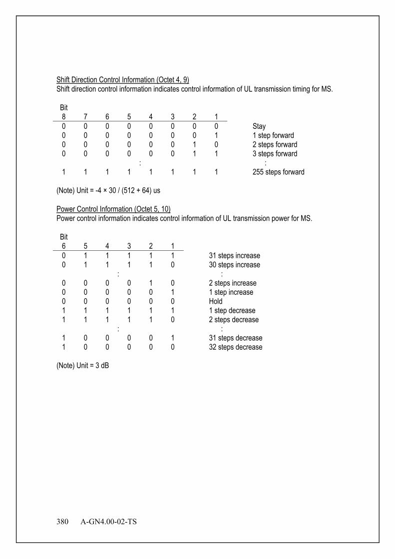
380 A-GN4.00-02-TS
Shift Direction Control Information (Octet 4, 9) Shift direction control information indicates control information of UL transmission timing for MS. Bit 8 7 6 5 4 3 2 1
0 0 0 0 0 0 0 0 Stay 0 0 0 0 0 0 0 1 1 step forward 0 0 0 0 0 0 1 0 2 steps forward 0 0 0 0 0 0 1 1 3 steps forward
: : 1 1 1 1 1 1 1 1 255 steps forward
(Note) Unit = -4 × 30 / (512 + 64) us Power Control Information (Octet 5, 10) Power control information indicates control information of UL transmission power for MS. Bit 6 5 4 3 2 1
0 1 1 1 1 1 31 steps increase 0 1 1 1 1 0 30 steps increase
: : 0 0 0 0 1 0 2 steps increase 0 0 0 0 0 1 1 step increase 0 0 0 0 0 0 Hold 1 1 1 1 1 1 1 step decrease 1 1 1 1 1 0 2 steps decrease
: : 1 0 0 0 0 1 31 steps decrease 1 0 0 0 0 0 32 steps decrease
(Note) Unit = 3 dB

A-GN4.00-02-TS 381
TCCH Pattern Number (Octet 6, 11) TCCH pattern number indicates the core-sequence number of UL TCCH used as shown in Appendix D. "2nd LCH assignment message (Octet 7-11) absent " can be set only to TCCH pattern of Octet 11. Bit 8 7 6 5
0 0 0 0 Core-sequence number 1 for OFDMA 0 0 0 1 Core-sequence number 2 for OFDMA 0 0 1 0 Core-sequence number 3 for OFDMA 0 0 1 1 Core-sequence number 4 for OFDMA 0 1 0 0 Core-sequence number 5 for OFDMA 0 1 0 1 Core-sequence number 6 for OFDMA 0 1 1 0 Core-sequence number 1 for SC 0 1 1 1 Core-sequence number 2 for SC 1 0 0 0 Core-sequence number 3 for SC 1 0 0 1 Core-sequence number 4 for SC 1 0 1 0 Core-sequence number 5 for SC 1 0 1 1 Core-sequence number 6 for SC
: : 1 1 1 0 Sub-slot number absent 1 1 1 1 2nd LCH assignment message (Octet 7-11) absent
Other Reserved ANCH MIMO (UL) (Octet 6, 11) ANCH MIMO (UL) indicates MIMO type for UL ANCH. Bit 4 3
0 0 SISO 0 1 2 layers STBC 1 0 4 layers STBC 1 1 Reserved
ANCH MIMO (DL) (Octet 6, 11) ANCH MIMO (DL) indicates MIMO type for DL ANCH. Bit 2 1
0 0 SISO 0 1 2 layers STBC 1 0 4 layers STBC 1 1 Reserved
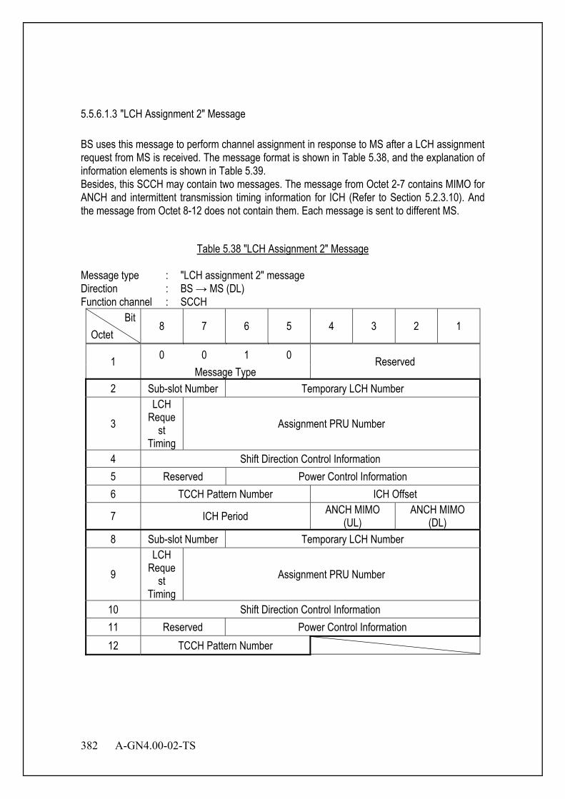
382 A-GN4.00-02-TS
5.5.6.1.3 "LCH Assignment 2" Message BS uses this message to perform channel assignment in response to MS after a LCH assignment request from MS is received. The message format is shown in Table 5.38, and the explanation of information elements is shown in Table 5.39. Besides, this SCCH may contain two messages. The message from Octet 2-7 contains MIMO for ANCH and intermittent transmission timing information for ICH (Refer to Section 5.2.3.10). And the message from Octet 8-12 does not contain them. Each message is sent to different MS.
Table 5.38 "LCH Assignment 2" Message
Message type : "LCH assignment 2" message Direction : BS → MS (DL) Function channel : SCCH
Bit Octet
8 7 6 5 4 3 2 1
1 0 0 1 0 Reserved Message Type
2 Sub-slot Number Temporary LCH Number
3 LCH
Request
Timing Assignment PRU Number
4 Shift Direction Control Information 5 Reserved Power Control Information 6 TCCH Pattern Number ICH Offset
7 ICH Period ANCH MIMO (UL)
ANCH MIMO (DL)
8 Sub-slot Number Temporary LCH Number
9 LCH
Request
Timing Assignment PRU Number
10 Shift Direction Control Information 11 Reserved Power Control Information 12 TCCH Pattern Number
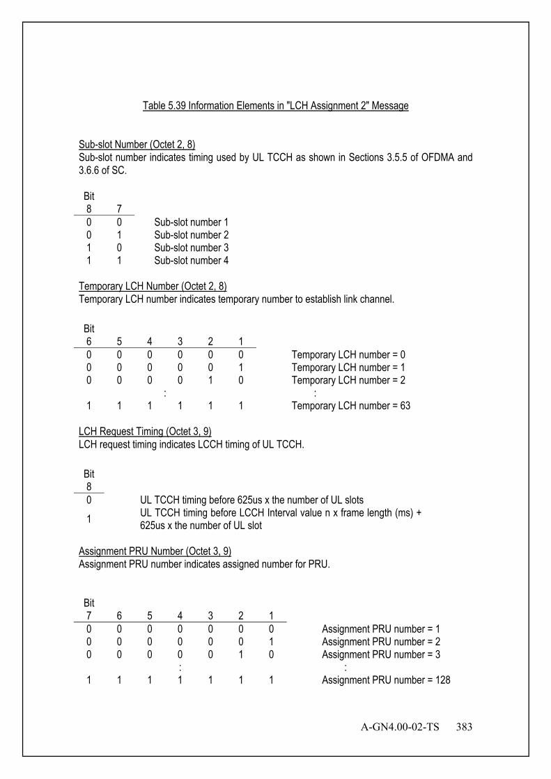
A-GN4.00-02-TS 383
Table 5.39 Information Elements in "LCH Assignment 2" Message
Sub-slot Number (Octet 2, 8) Sub-slot number indicates timing used by UL TCCH as shown in Sections 3.5.5 of OFDMA and 3.6.6 of SC. Bit 8 7
0 0 Sub-slot number 1 0 1 Sub-slot number 2 1 0 Sub-slot number 3 1 1 Sub-slot number 4
Temporary LCH Number (Octet 2, 8) Temporary LCH number indicates temporary number to establish link channel. Bit 6 5 4 3 2 1
0 0 0 0 0 0 Temporary LCH number = 0 0 0 0 0 0 1 Temporary LCH number = 1 0 0 0 0 1 0 Temporary LCH number = 2
: : 1 1 1 1 1 1 Temporary LCH number = 63
LCH Request Timing (Octet 3, 9) LCH request timing indicates LCCH timing of UL TCCH. Bit 8
0 UL TCCH timing before 625us x the number of UL slots 1 UL TCCH timing before LCCH Interval value n x frame length (ms) +
625us x the number of UL slot Assignment PRU Number (Octet 3, 9) Assignment PRU number indicates assigned number for PRU. Bit 7 6 5 4 3 2 1
0 0 0 0 0 0 0 Assignment PRU number = 1 0 0 0 0 0 0 1 Assignment PRU number = 2 0 0 0 0 0 1 0 Assignment PRU number = 3
: : 1 1 1 1 1 1 1 Assignment PRU number = 128

384 A-GN4.00-02-TS
Shift Direction Control Information (Octet 4, 10) Shift direction control information indicates control information of UL transmission timing for MS. Bit 8 7 6 5 4 3 2 1
0 0 0 0 0 0 0 0 Stay 0 0 0 0 0 0 0 1 1 step forward 0 0 0 0 0 0 1 0 2 steps forward 0 0 0 0 0 0 1 1 3 steps forward
: : 1 1 1 1 1 1 1 1 255 steps forward
(Note) Unit = -4 × 30 / (512 + 64) us Power Control Information (Octet 5, 11) Power control information indicates control information of UL transmission power for MS. Bit 6 5 4 3 2 1
0 1 1 1 1 1 31 steps increase 0 1 1 1 1 0 30 steps increase
: : 0 0 0 0 1 0 2 steps increase 0 0 0 0 0 1 1 step increase 0 0 0 0 0 0 Hold 1 1 1 1 1 1 1 step decrease 1 1 1 1 1 0 2 steps decrease
: : 1 0 0 0 0 1 31 steps decrease 1 0 0 0 0 0 32 steps decrease
(Note) Unit = 3 dB
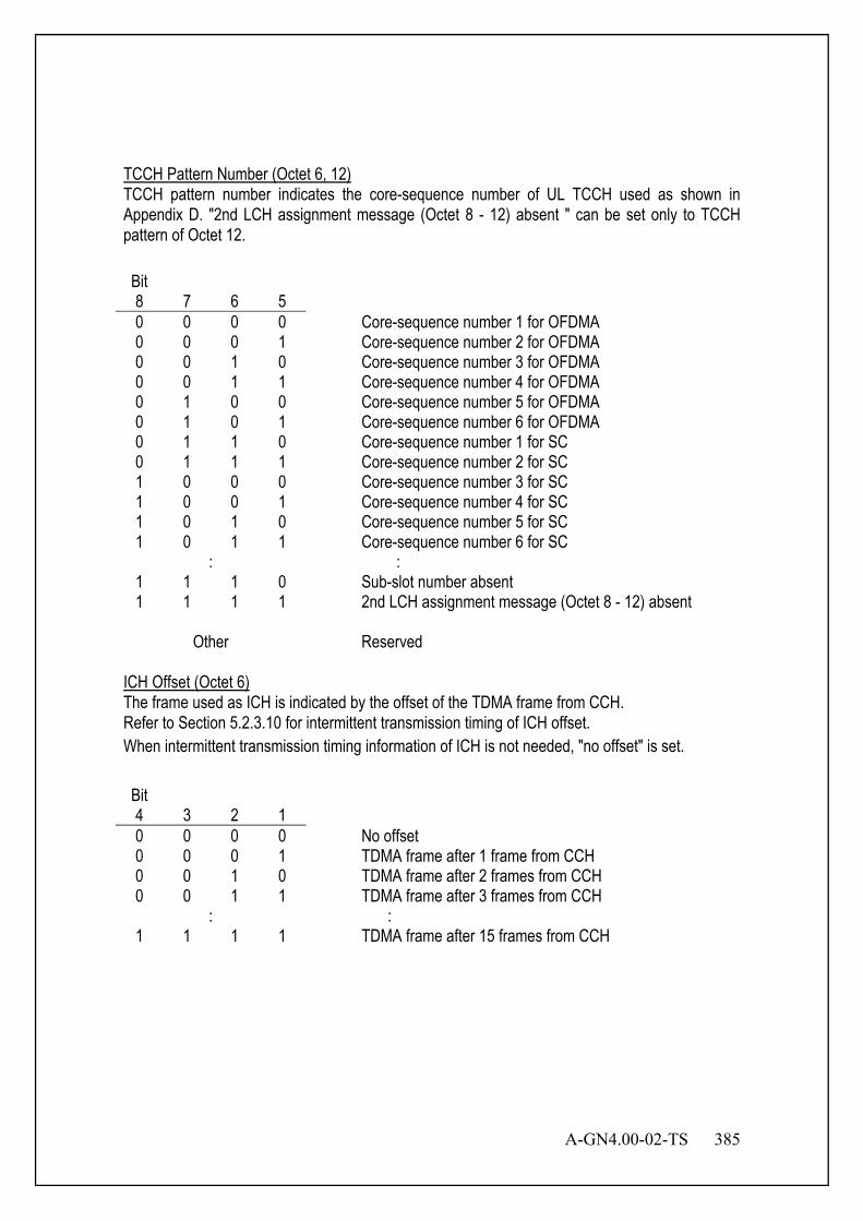
A-GN4.00-02-TS 385
TCCH Pattern Number (Octet 6, 12) TCCH pattern number indicates the core-sequence number of UL TCCH used as shown in Appendix D. "2nd LCH assignment message (Octet 8 - 12) absent " can be set only to TCCH pattern of Octet 12. Bit 8 7 6 5
0 0 0 0 Core-sequence number 1 for OFDMA 0 0 0 1 Core-sequence number 2 for OFDMA 0 0 1 0 Core-sequence number 3 for OFDMA 0 0 1 1 Core-sequence number 4 for OFDMA 0 1 0 0 Core-sequence number 5 for OFDMA 0 1 0 1 Core-sequence number 6 for OFDMA 0 1 1 0 Core-sequence number 1 for SC 0 1 1 1 Core-sequence number 2 for SC 1 0 0 0 Core-sequence number 3 for SC 1 0 0 1 Core-sequence number 4 for SC 1 0 1 0 Core-sequence number 5 for SC 1 0 1 1 Core-sequence number 6 for SC
: : 1 1 1 0 Sub-slot number absent 1 1 1 1 2nd LCH assignment message (Octet 8 - 12) absent
Other Reserved ICH Offset (Octet 6) The frame used as ICH is indicated by the offset of the TDMA frame from CCH. Refer to Section 5.2.3.10 for intermittent transmission timing of ICH offset. When intermittent transmission timing information of ICH is not needed, "no offset" is set. Bit 4 3 2 1
0 0 0 0 No offset 0 0 0 1 TDMA frame after 1 frame from CCH 0 0 1 0 TDMA frame after 2 frames from CCH 0 0 1 1 TDMA frame after 3 frames from CCH
: : 1 1 1 1 TDMA frame after 15 frames from CCH
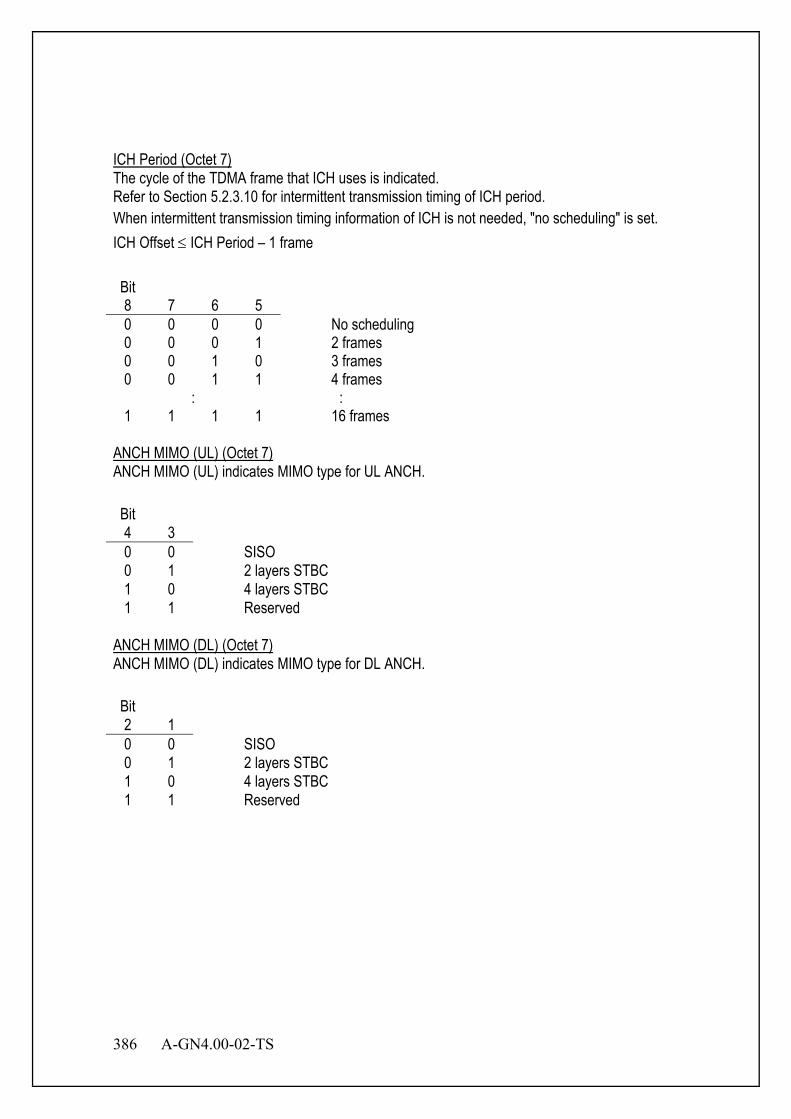
386 A-GN4.00-02-TS
ICH Period (Octet 7) The cycle of the TDMA frame that ICH uses is indicated. Refer to Section 5.2.3.10 for intermittent transmission timing of ICH period. When intermittent transmission timing information of ICH is not needed, "no scheduling" is set. ICH Offset ≤ ICH Period – 1 frame Bit 8 7 6 5
0 0 0 0 No scheduling 0 0 0 1 2 frames 0 0 1 0 3 frames 0 0 1 1 4 frames
: : 1 1 1 1 16 frames
ANCH MIMO (UL) (Octet 7) ANCH MIMO (UL) indicates MIMO type for UL ANCH. Bit 4 3
0 0 SISO 0 1 2 layers STBC 1 0 4 layers STBC 1 1 Reserved
ANCH MIMO (DL) (Octet 7) ANCH MIMO (DL) indicates MIMO type for DL ANCH. Bit 2 1
0 0 SISO 0 1 2 layers STBC 1 0 4 layers STBC 1 1 Reserved
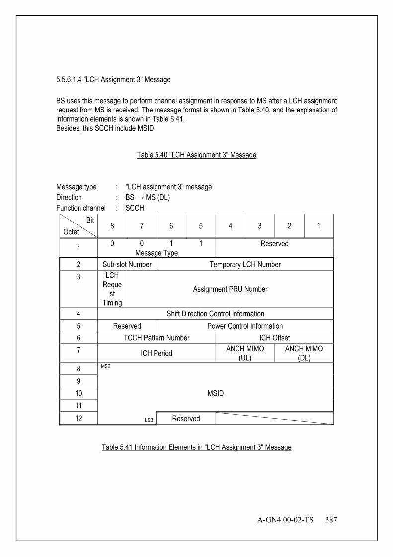
A-GN4.00-02-TS 387
5.5.6.1.4 "LCH Assignment 3" Message BS uses this message to perform channel assignment in response to MS after a LCH assignment request from MS is received. The message format is shown in Table 5.40, and the explanation of information elements is shown in Table 5.41. Besides, this SCCH include MSID.
Table 5.40 "LCH Assignment 3" Message
Message type : "LCH assignment 3" message Direction : BS → MS (DL) Function channel : SCCH
Bit Octet
8 7 6 5 4 3 2 1
1 0 0 1 1 Reserved Message Type
2 Sub-slot Number Temporary LCH Number 3 LCH
Request
Timing Assignment PRU Number
4 Shift Direction Control Information 5 Reserved Power Control Information 6 TCCH Pattern Number ICH Offset 7 ICH Period ANCH MIMO
(UL) ANCH MIMO
(DL) 8 MSB
9 MSID 10
11 12 LSB Reserved
Table 5.41 Information Elements in "LCH Assignment 3" Message
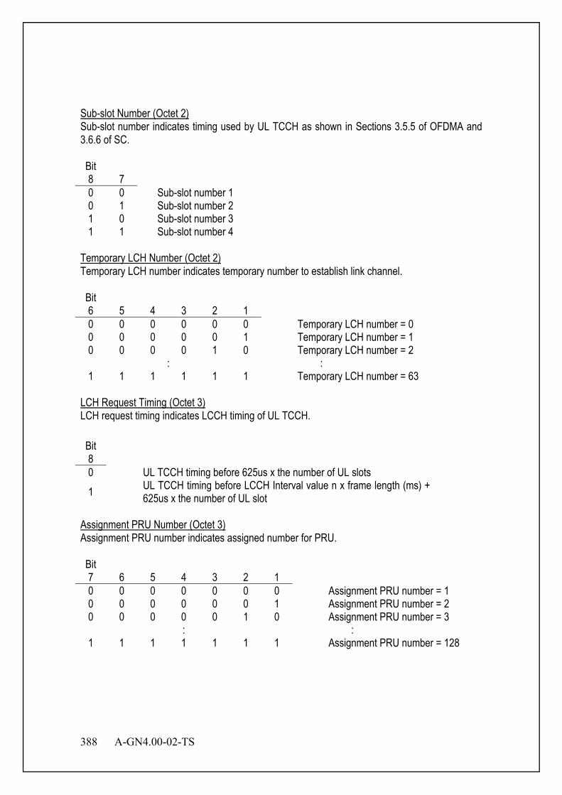
388 A-GN4.00-02-TS
Sub-slot Number (Octet 2) Sub-slot number indicates timing used by UL TCCH as shown in Sections 3.5.5 of OFDMA and 3.6.6 of SC. Bit 8 7
0 0 Sub-slot number 1 0 1 Sub-slot number 2 1 0 Sub-slot number 3 1 1 Sub-slot number 4
Temporary LCH Number (Octet 2) Temporary LCH number indicates temporary number to establish link channel. Bit 6 5 4 3 2 1
0 0 0 0 0 0 Temporary LCH number = 0 0 0 0 0 0 1 Temporary LCH number = 1 0 0 0 0 1 0 Temporary LCH number = 2
: : 1 1 1 1 1 1 Temporary LCH number = 63
LCH Request Timing (Octet 3) LCH request timing indicates LCCH timing of UL TCCH. Bit 8
0 UL TCCH timing before 625us x the number of UL slots 1 UL TCCH timing before LCCH Interval value n x frame length (ms) +
625us x the number of UL slot Assignment PRU Number (Octet 3) Assignment PRU number indicates assigned number for PRU. Bit 7 6 5 4 3 2 1
0 0 0 0 0 0 0 Assignment PRU number = 1 0 0 0 0 0 0 1 Assignment PRU number = 2 0 0 0 0 0 1 0 Assignment PRU number = 3
: : 1 1 1 1 1 1 1 Assignment PRU number = 128
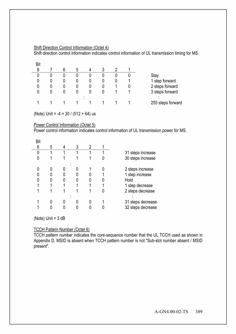
A-GN4.00-02-TS 389
Shift Direction Control Information (Octet 4) Shift direction control information indicates control information of UL transmission timing for MS. Bit 8 7 6 5 4 3 2 1
0 0 0 0 0 0 0 0 Stay 0 0 0 0 0 0 0 1 1 step forward 0 0 0 0 0 0 1 0 2 steps forward 0 0 0 0 0 0 1 1 3 steps forward
: : 1 1 1 1 1 1 1 1 255 steps forward
(Note) Unit = -4 × 30 / (512 + 64) us Power Control Information (Octet 5) Power control information indicates control information of UL transmission power for MS. Bit 6 5 4 3 2 1
0 1 1 1 1 1 31 steps increase 0 1 1 1 1 0 30 steps increase
: 0 0 0 0 1 0 2 steps increase 0 0 0 0 0 1 1 step increase 0 0 0 0 0 0 Hold 1 1 1 1 1 1 1 step decrease 1 1 1 1 1 0 2 steps decrease
: : 1 0 0 0 0 1 31 steps decrease 1 0 0 0 0 0 32 steps decrease
(Note) Unit = 3 dB TCCH Pattern Number (Octet 6) TCCH pattern number indicates the core-sequence number that the UL TCCH used as shown in Appendix D. MSID is absent when TCCH pattern number is not "Sub-slot number absent / MSID present".
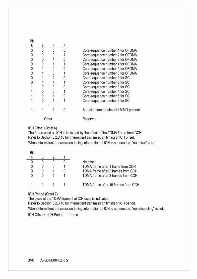
390 A-GN4.00-02-TS
Bit 8 7 6 5
0 0 0 0 Core-sequence number 1 for OFDMA 0 0 0 1 Core-sequence number 2 for OFDMA 0 0 1 0 Core-sequence number 3 for OFDMA 0 0 1 1 Core-sequence number 4 for OFDMA 0 1 0 0 Core-sequence number 5 for OFDMA 0 1 0 1 Core-sequence number 6 for OFDMA 0 1 1 0 Core-sequence number 1 for SC 0 1 1 1 Core-sequence number 2 for SC 1 0 0 0 Core-sequence number 3 for SC 1 0 0 1 Core-sequence number 4 for SC 1 0 1 0 Core-sequence number 5 for SC 1 0 1 1 Core-sequence number 6 for SC
: : 1 1 1 0 Sub-slot number absent / MSID present
Other Reserved
ICH Offset (Octet 6) The frame used as ICH is indicated by the offset of the TDMA frame from CCH. Refer to Section 5.2.3.10 for intermittent transmission timing of ICH offset. When intermittent transmission timing information of ICH is not needed, "no offset" is set. Bit 4 3 2 1
0 0 0 0 No offset 0 0 0 1 TDMA frame after 1 frame from CCH 0 0 1 0 TDMA frame after 2 frames from CCH 0 0 1 1 TDMA frame after 3 frames from CCH
: : 1 1 1 1 TDMA frame after 15 frames from CCH
ICH Period (Octet 7) The cycle of the TDMA frame that ICH uses is indicated. Refer to Section 5.2.3.10 for intermittent transmission timing of ICH period. When intermittent transmission timing information of ICH is not needed, "no scheduling" is set. ICH Offset ≤ ICH Period – 1 frame

A-GN4.00-02-TS 391
Bit 8 7 6 5
0 0 0 0 No scheduling 0 0 0 1 2 frames 0 0 1 0 3 frames 0 0 1 1 4 frames
: : 1 1 1 1 16 frames
ANCH MIMO (UL) (Octet 7) ANCH MIMO (UL) indicates MIMO type for UL ANCH. Bit 4 3
0 0 SISO 0 1 2 layers STBC 1 0 4 layers STBC 1 1 Reserved
ANCH MIMO (DL) (Octet 7) ANCH MIMO (DL) indicates MIMO type for DL ANCH. Bit 2 1
0 0 SISO 0 1 2 layers STBC 1 0 4 layers STBC 1 1 Reserved
MSID (Octet 8 - 12) The length of MSID is 34 bits.

392 A-GN4.00-02-TS
5.5.6.1.5 "LCH Assignment Standby" Message BS uses this message to inform BS to standby. The message format is shown in Table 5.42, and the explanation of information elements is shown in Table 5.43.
Table 5.42 "LCH Assignment Standby" Message
Message type : "LCH assignment standby" message Direction : BS → MS (DL) Function channel : SCCH
Bit Octet
8 7 6 5 4 3 2 1
1 0 1 0 0 Reserved Message Type 2 Sub-slot Number Temporary LCH Number
3 LCH
Request
Timing Reserved Cause
4 Reserved
5 6 TCCH Pattern Number Reserved 7 Sub-slot Number Temporary LCH Number
8 LCH
Request
Timing Assignment PRU Number
9 Shift Direction Control Information 10 Reserved Power Control Information 11 TCCH Pattern Number ICH Offset 12 ICH Period

A-GN4.00-02-TS 393
Table 5.43 Information Elements in "LCH Assignment Standby" Message
Sub-slot Number (Octet 2, 7) Sub-slot number indicates timing used by UL TCCH as shown in Sections 3.5.5 of OFDMA and 3.6.6 of SC. Bit 8 7
0 0 Sub-slot number 1 0 1 Sub-slot number 2 1 0 Sub-slot number 3 1 1 Sub-slot number 4
Temporary LCH Number (Octet 2, 7) Temporary LCH number indicates temporary number to establish link channel. Bit 6 5 4 3 2 1
0 0 0 0 0 0 Temporary LCH number = 0 0 0 0 0 0 1 Temporary LCH number = 1 0 0 0 0 1 0 Temporary LCH number = 2
: : 1 1 1 1 1 1 Temporary LCH number = 63
LCH Request Timing (Octet 3, 8) LCH request timing indicates LCCH timing of UL TCCH. Bit 8
0 UL TCCH timing before 625us x the number of UL slots 1 UL TCCH timing before LCCH Interval value n x frame length (ms) +
625us x the number of UL slot Cause (Octet 3) Cause indicates standby reason. Bit 5 4 3 2 1
0 0 0 0 0 Reserved 0 0 0 0 1 All BS slots in use 0 0 0 1 0 No BS free channel 0 0 0 1 1 No free outgoing line on wire side 0 0 1 0 0 LCH type disagreement 0 0 1 0 1 Traffic restriction 0 0 1 1 0 Relevant BS use impossible (zone selection impossible)
Other Reserved
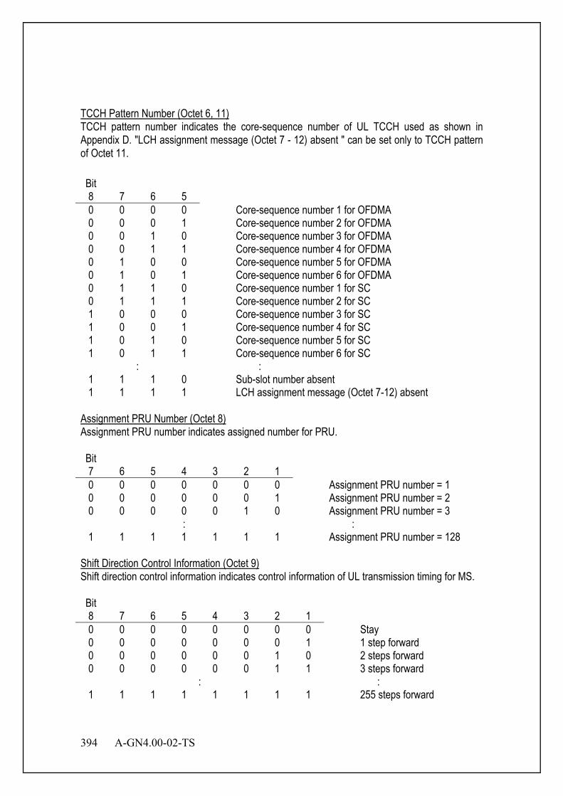
394 A-GN4.00-02-TS
TCCH Pattern Number (Octet 6, 11) TCCH pattern number indicates the core-sequence number of UL TCCH used as shown in Appendix D. "LCH assignment message (Octet 7 - 12) absent " can be set only to TCCH pattern of Octet 11. Bit 8 7 6 5
0 0 0 0 Core-sequence number 1 for OFDMA 0 0 0 1 Core-sequence number 2 for OFDMA 0 0 1 0 Core-sequence number 3 for OFDMA 0 0 1 1 Core-sequence number 4 for OFDMA 0 1 0 0 Core-sequence number 5 for OFDMA 0 1 0 1 Core-sequence number 6 for OFDMA 0 1 1 0 Core-sequence number 1 for SC 0 1 1 1 Core-sequence number 2 for SC 1 0 0 0 Core-sequence number 3 for SC 1 0 0 1 Core-sequence number 4 for SC 1 0 1 0 Core-sequence number 5 for SC 1 0 1 1 Core-sequence number 6 for SC
: : 1 1 1 0 Sub-slot number absent 1 1 1 1 LCH assignment message (Octet 7-12) absent
Assignment PRU Number (Octet 8) Assignment PRU number indicates assigned number for PRU. Bit 7 6 5 4 3 2 1
0 0 0 0 0 0 0 Assignment PRU number = 1 0 0 0 0 0 0 1 Assignment PRU number = 2 0 0 0 0 0 1 0 Assignment PRU number = 3
: : 1 1 1 1 1 1 1 Assignment PRU number = 128
Shift Direction Control Information (Octet 9) Shift direction control information indicates control information of UL transmission timing for MS. Bit 8 7 6 5 4 3 2 1
0 0 0 0 0 0 0 0 Stay 0 0 0 0 0 0 0 1 1 step forward 0 0 0 0 0 0 1 0 2 steps forward 0 0 0 0 0 0 1 1 3 steps forward
: : 1 1 1 1 1 1 1 1 255 steps forward
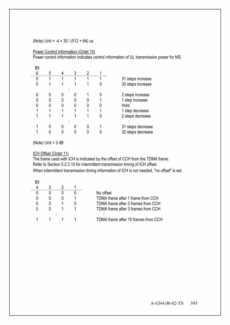
A-GN4.00-02-TS 395
(Note) Unit = -4 × 30 / (512 + 64) us Power Control Information (Octet 10) Power control information indicates control information of UL transmission power for MS. Bit 6 5 4 3 2 1
0 1 1 1 1 1 31 steps increase 0 1 1 1 1 0 30 steps increase
: 0 0 0 0 1 0 2 steps increase 0 0 0 0 0 1 1 step increase 0 0 0 0 0 0 Hold 1 1 1 1 1 1 1 step decrease 1 1 1 1 1 0 2 steps decrease
: : 1 0 0 0 0 1 31 steps decrease 1 0 0 0 0 0 32 steps decrease
(Note) Unit = 3 dB ICH Offset (Octet 11) The frame used with ICH is indicated by the offset of CCH from the TDMA frame. Refer to Section 5.2.3.10 for intermittent transmission timing of ICH offset. When intermittent transmission timing information of ICH is not needed, "no offset" is set. Bit 4 3 2 1
0 0 0 0 No offset 0 0 0 1 TDMA frame after 1 frame from CCH 0 0 1 0 TDMA frame after 2 frames from CCH 0 0 1 1 TDMA frame after 3 frames from CCH
: : 1 1 1 1 TDMA frame after 15 frames from CCH
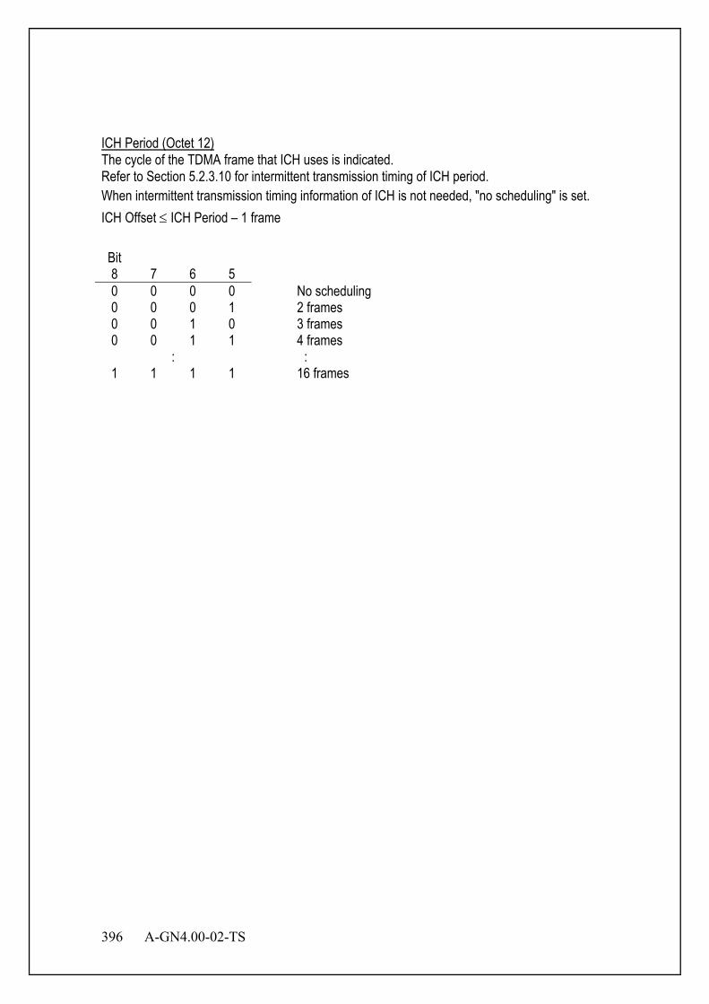
396 A-GN4.00-02-TS
ICH Period (Octet 12) The cycle of the TDMA frame that ICH uses is indicated. Refer to Section 5.2.3.10 for intermittent transmission timing of ICH period. When intermittent transmission timing information of ICH is not needed, "no scheduling" is set. ICH Offset ≤ ICH Period – 1 frame Bit 8 7 6 5
0 0 0 0 No scheduling 0 0 0 1 2 frames 0 0 1 0 3 frames 0 0 1 1 4 frames
: : 1 1 1 1 16 frames
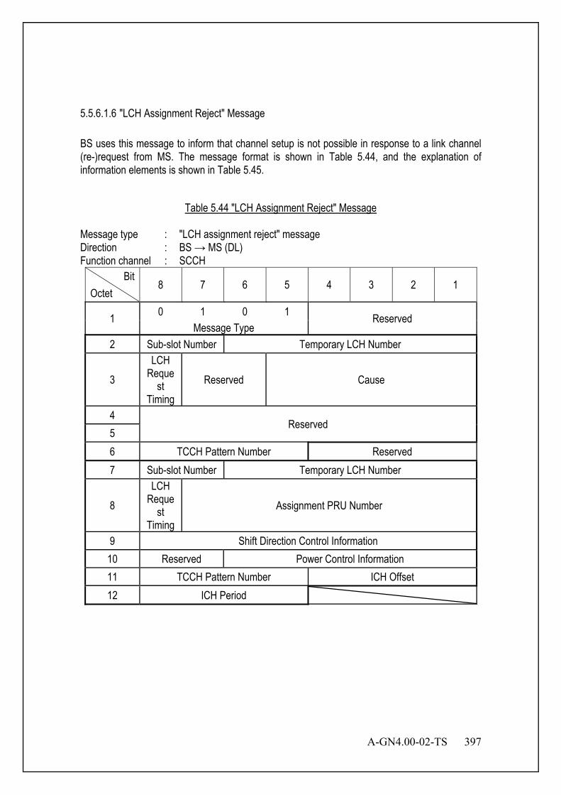
A-GN4.00-02-TS 397
5.5.6.1.6 "LCH Assignment Reject" Message BS uses this message to inform that channel setup is not possible in response to a link channel (re-)request from MS. The message format is shown in Table 5.44, and the explanation of information elements is shown in Table 5.45.
Table 5.44 "LCH Assignment Reject" Message
Message type : "LCH assignment reject" message Direction : BS → MS (DL) Function channel : SCCH
Bit Octet
8 7 6 5 4 3 2 1
1 0 1 0 1 Reserved Message Type
2 Sub-slot Number Temporary LCH Number
3 LCH
Request
Timing Reserved Cause
4 Reserved
5 6 TCCH Pattern Number Reserved 7 Sub-slot Number Temporary LCH Number
8 LCH
Request
Timing Assignment PRU Number
9 Shift Direction Control Information 10 Reserved Power Control Information 11 TCCH Pattern Number ICH Offset 12 ICH Period
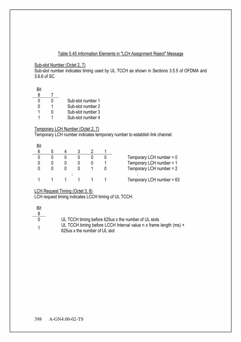
398 A-GN4.00-02-TS
Table 5.45 Information Elements in "LCH Assignment Reject" Message
Sub-slot Number (Octet 2, 7) Sub-slot number indicates timing used by UL TCCH as shown in Sections 3.5.5 of OFDMA and 3.6.6 of SC. Bit 8 7
0 0 Sub-slot number 1 0 1 Sub-slot number 2 1 0 Sub-slot number 3 1 1 Sub-slot number 4
Temporary LCH Number (Octet 2, 7) Temporary LCH number indicates temporary number to establish link channel. Bit 6 5 4 3 2 1
0 0 0 0 0 0 Temporary LCH number = 0 0 0 0 0 0 1 Temporary LCH number = 1 0 0 0 0 1 0 Temporary LCH number = 2
: : 1 1 1 1 1 1 Temporary LCH number = 63
LCH Request Timing (Octet 3, 8) LCH request timing indicates LCCH timing of UL TCCH. Bit 8
0 UL TCCH timing before 625us x the number of UL slots 1 UL TCCH timing before LCCH Interval value n x frame length (ms) +
625us x the number of UL slot
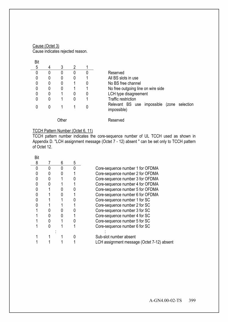
A-GN4.00-02-TS 399
Cause (Octet 3) Cause indicates rejected reason. Bit 5 4 3 2 1
0 0 0 0 0 Reserved 0 0 0 0 1 All BS slots in use 0 0 0 1 0 No BS free channel 0 0 0 1 1 No free outgoing line on wire side 0 0 1 0 0 LCH type disagreement 0 0 1 0 1 Traffic restriction 0 0 1 1 0 Relevant BS use impossible (zone selection
impossible)
Other Reserved TCCH Pattern Number (Octet 6, 11) TCCH pattern number indicates the core-sequence number of UL TCCH used as shown in Appendix D. "LCH assignment message (Octet 7 - 12) absent " can be set only to TCCH pattern of Octet 12. Bit 8 7 6 5
0 0 0 0 Core-sequence number 1 for OFDMA 0 0 0 1 Core-sequence number 2 for OFDMA 0 0 1 0 Core-sequence number 3 for OFDMA 0 0 1 1 Core-sequence number 4 for OFDMA 0 1 0 0 Core-sequence number 5 for OFDMA 0 1 0 1 Core-sequence number 6 for OFDMA 0 1 1 0 Core-sequence number 1 for SC 0 1 1 1 Core-sequence number 2 for SC 1 0 0 0 Core-sequence number 3 for SC 1 0 0 1 Core-sequence number 4 for SC 1 0 1 0 Core-sequence number 5 for SC 1 0 1 1 Core-sequence number 6 for SC
: : 1 1 1 0 Sub-slot number absent 1 1 1 1 LCH assignment message (Octet 7-12) absent
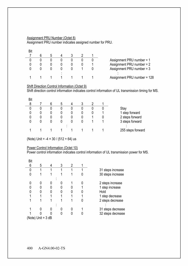
400 A-GN4.00-02-TS
Assignment PRU Number (Octet 8) Assignment PRU number indicates assigned number for PRU. Bit 7 6 5 4 3 2 1
0 0 0 0 0 0 0 Assignment PRU number = 1 0 0 0 0 0 0 1 Assignment PRU number = 2 0 0 0 0 0 1 0 Assignment PRU number = 3
: : 1 1 1 1 1 1 1 Assignment PRU number = 128
Shift Direction Control Information (Octet 9) Shift direction control information indicates control information of UL transmission timing for MS. Bit 8 7 6 5 4 3 2 1
0 0 0 0 0 0 0 0 Stay 0 0 0 0 0 0 0 1 1 step forward 0 0 0 0 0 0 1 0 2 steps forward 0 0 0 0 0 0 1 1 3 steps forward
: : 1 1 1 1 1 1 1 1 255 steps forward
(Note) Unit = -4 × 30 / (512 + 64) us Power Control Information (Octet 10) Power control information indicates control information of UL transmission power for MS. Bit 6 5 4 3 2 1
0 1 1 1 1 1 31 steps increase 0 1 1 1 1 0 30 steps increase
: 0 0 0 0 1 0 2 steps increase 0 0 0 0 0 1 1 step increase 0 0 0 0 0 0 Hold 1 1 1 1 1 1 1 step decrease 1 1 1 1 1 0 2 steps decrease
: : 1 0 0 0 0 1 31 steps decrease 1 0 0 0 0 0 32 steps decrease
(Note) Unit = 3 dB
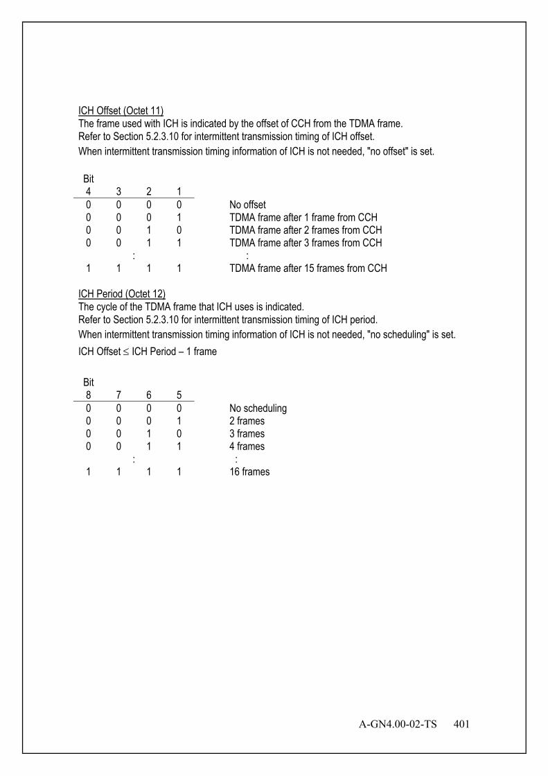
A-GN4.00-02-TS 401
ICH Offset (Octet 11) The frame used with ICH is indicated by the offset of CCH from the TDMA frame. Refer to Section 5.2.3.10 for intermittent transmission timing of ICH offset. When intermittent transmission timing information of ICH is not needed, "no offset" is set. Bit 4 3 2 1
0 0 0 0 No offset 0 0 0 1 TDMA frame after 1 frame from CCH 0 0 1 0 TDMA frame after 2 frames from CCH 0 0 1 1 TDMA frame after 3 frames from CCH
: : 1 1 1 1 TDMA frame after 15 frames from CCH
ICH Period (Octet 12) The cycle of the TDMA frame that ICH uses is indicated. Refer to Section 5.2.3.10 for intermittent transmission timing of ICH period. When intermittent transmission timing information of ICH is not needed, "no scheduling" is set. ICH Offset ≤ ICH Period – 1 frame Bit 8 7 6 5
0 0 0 0 No scheduling 0 0 0 1 2 frames 0 0 1 0 3 frames 0 0 1 1 4 frames
: : 1 1 1 1 16 frames
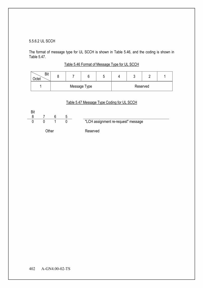
402 A-GN4.00-02-TS
5.5.6.2 UL SCCH The format of message type for UL SCCH is shown in Table 5.46, and the coding is shown in Table 5.47.
Table 5.46 Format of Message Type for UL SCCH
Bit Octet 8 7 6 5 4 3 2 1
1 Message Type Reserved
Table 5.47 Message Type Coding for UL SCCH
Bit 8 7 6 5
0 0 1 0 "LCH assignment re-request" message
Other Reserved
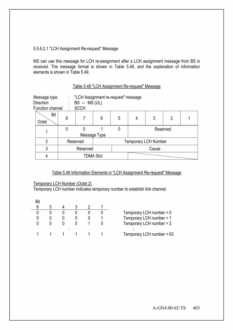
A-GN4.00-02-TS 403
5.5.6.2.1 "LCH Assignment Re-request" Message MS can use this message for LCH re-assignment after a LCH assignment message from BS is received. The message format is shown in Table 5.48, and the explanation of information elements is shown in Table 5.49.
Table 5.48 "LCH Assignment Re-request" Message
Message type : "LCH Assignment re-request" message Direction : BS ← MS (UL) Function channel : SCCH
Bit Octet
8 7 6 5 4 3 2 1
1 0 0 1 0 Reserved Message Type
2 Reserved Temporary LCH Number 3 Reserved Cause 4 TDMA Slot
Table 5.49 Information Elements in "LCH Assignment Re-request" Message
Temporary LCH Number (Octet 2) Temporary LCH number indicates temporary number to establish link channel. Bit 6 5 4 3 2 1 0 0 0 0 0 0 Temporary LCH number = 0 0 0 0 0 0 1 Temporary LCH number = 1 0 0 0 0 1 0 Temporary LCH number = 2
: : 1 1 1 1 1 1 Temporary LCH number = 63
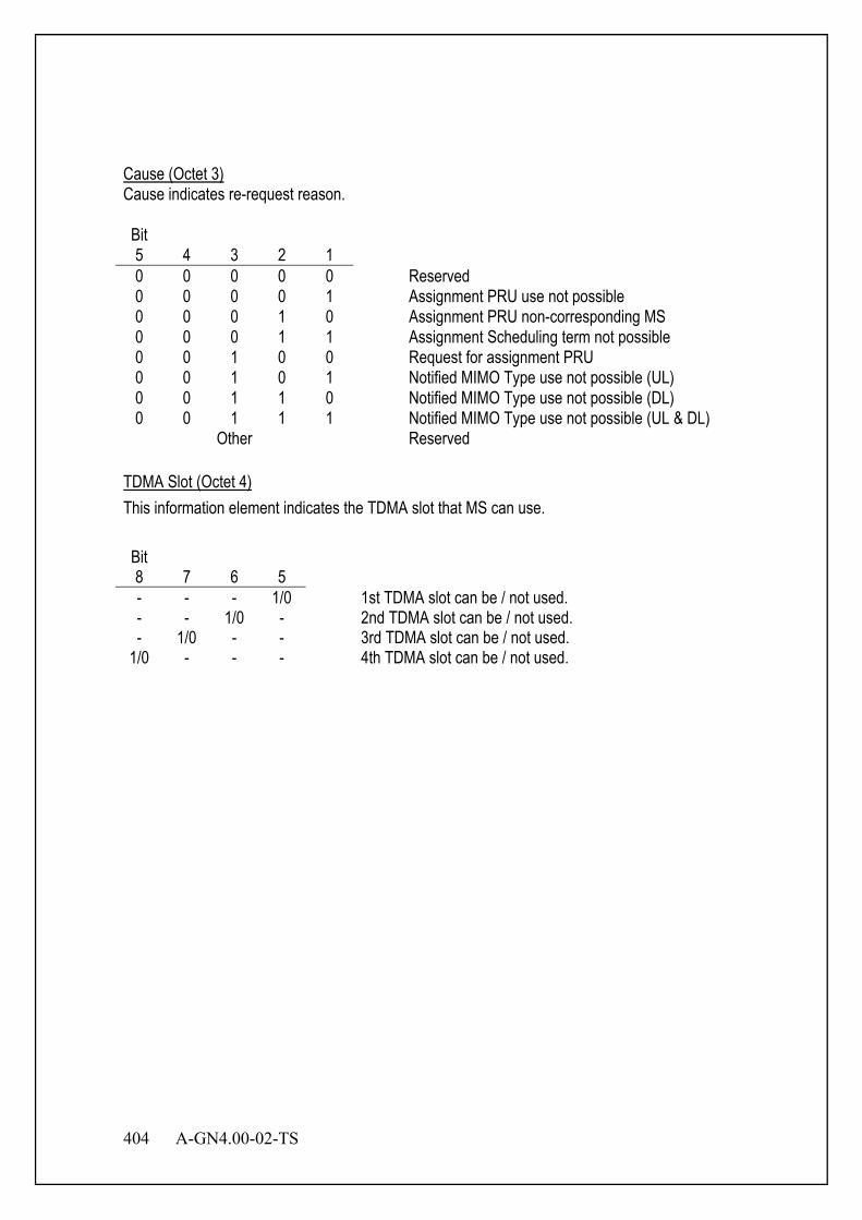
404 A-GN4.00-02-TS
Cause (Octet 3) Cause indicates re-request reason. Bit 5 4 3 2 1 0 0 0 0 0 Reserved 0 0 0 0 1 Assignment PRU use not possible 0 0 0 1 0 Assignment PRU non-corresponding MS 0 0 0 1 1 Assignment Scheduling term not possible 0 0 1 0 0 Request for assignment PRU 0 0 1 0 1 Notified MIMO Type use not possible (UL) 0 0 1 1 0 Notified MIMO Type use not possible (DL) 0 0 1 1 1 Notified MIMO Type use not possible (UL & DL)
Other Reserved TDMA Slot (Octet 4) This information element indicates the TDMA slot that MS can use. Bit 8 7 6 5 - - - 1/0 1st TDMA slot can be / not used. - - 1/0 - 2nd TDMA slot can be / not used. - 1/0 - - 3rd TDMA slot can be / not used.
1/0 - - - 4th TDMA slot can be / not used.

A-GN4.00-02-TS 405
Chapter 6 Channel Assignment
6.1 Overview This chapter describes the link establishment control, the channel assignment control and the connection control specification for radio-link. In Section 6.2, link establishment control is described. Channel assignment control is described in Section 6.3; and connection control is described in Section 6.4. Section 6.4 also defines the two channel access modes called “Fast access channel based on MAP mode (FM-Mode)” and “high Quality channel based on carrier sensing mode (QS-Mode)”. FM-Mode is used for high-speed packet access. PRUs of EXCH are shared among MSs in FM-Mode. QS-Mode is used mainly for applications which require guaranteed bandwidth or low latency. One PRU is dedicatedly assigned to one MS while the data traffic is continued in QS-Mode. Radio state management is defined in Section 6.5; and parameters introduced in this chapter are summarized in Section 6.9. 6.2 Link Establishment Control The sequences of incoming call and outgoing call are shown in Figure 6.1 and Figure 6.2.
MS
CCH ICH
BS
CCH ICH
TCCH
SCCH
Communicating
PCH
Request for link channel establishment
Paging of coming call information
Allocate a channel
ICCH Confirmation of channel assign
Figure 6.1 Incoming Call Sequence
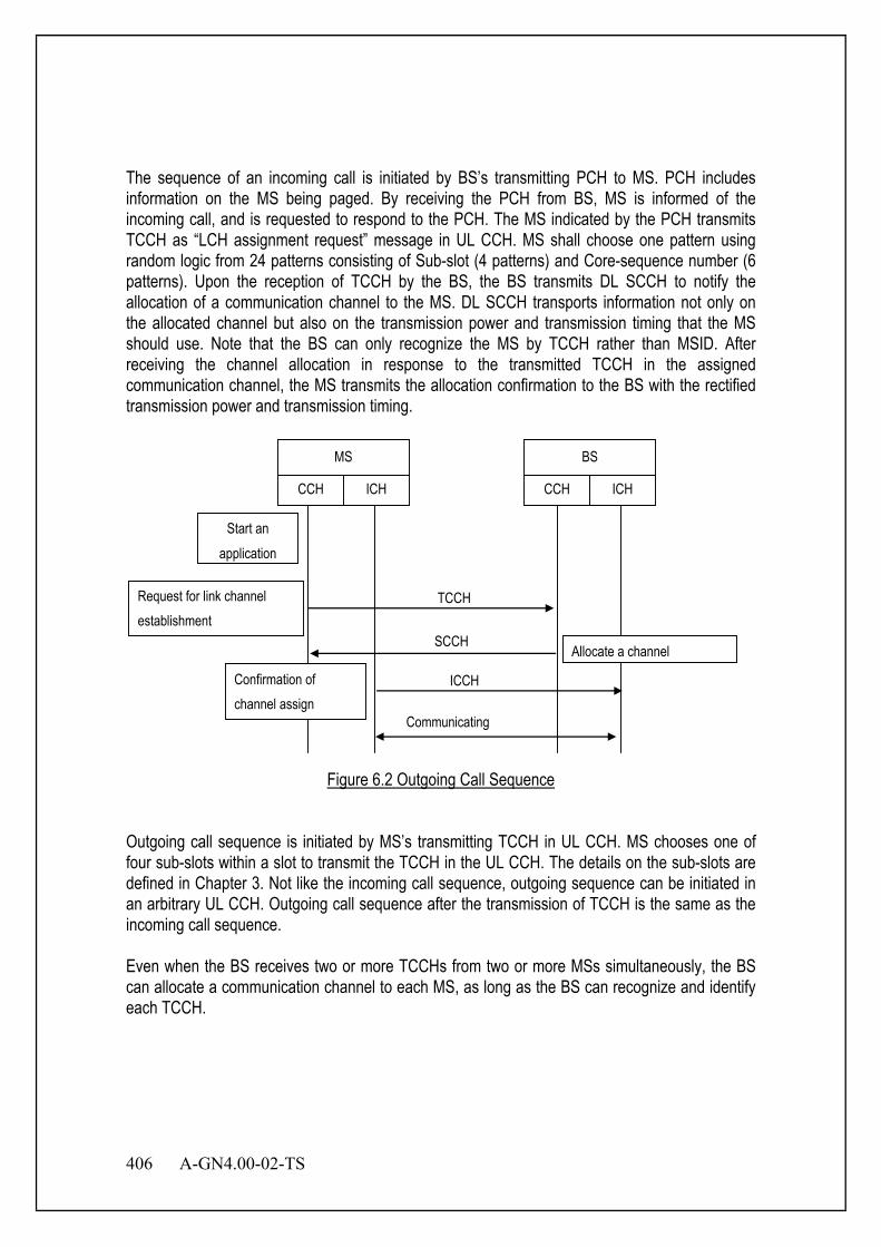
406 A-GN4.00-02-TS
The sequence of an incoming call is initiated by BS’s transmitting PCH to MS. PCH includes information on the MS being paged. By receiving the PCH from BS, MS is informed of the incoming call, and is requested to respond to the PCH. The MS indicated by the PCH transmits TCCH as “LCH assignment request” message in UL CCH. MS shall choose one pattern using random logic from 24 patterns consisting of Sub-slot (4 patterns) and Core-sequence number (6 patterns). Upon the reception of TCCH by the BS, the BS transmits DL SCCH to notify the allocation of a communication channel to the MS. DL SCCH transports information not only on the allocated channel but also on the transmission power and transmission timing that the MS should use. Note that the BS can only recognize the MS by TCCH rather than MSID. After receiving the channel allocation in response to the transmitted TCCH in the assigned communication channel, the MS transmits the allocation confirmation to the BS with the rectified transmission power and transmission timing. MS
CCH ICH
BS
CCH ICH
TCCH
SCCH
Communicating
Request for link channel establishment
Allocate a channel
Start an application
ICCH Confirmation of channel assign
Figure 6.2 Outgoing Call Sequence
Outgoing call sequence is initiated by MS’s transmitting TCCH in UL CCH. MS chooses one of four sub-slots within a slot to transmit the TCCH in the UL CCH. The details on the sub-slots are defined in Chapter 3. Not like the incoming call sequence, outgoing sequence can be initiated in an arbitrary UL CCH. Outgoing call sequence after the transmission of TCCH is the same as the incoming call sequence. Even when the BS receives two or more TCCHs from two or more MSs simultaneously, the BS can allocate a communication channel to each MS, as long as the BS can recognize and identify each TCCH.
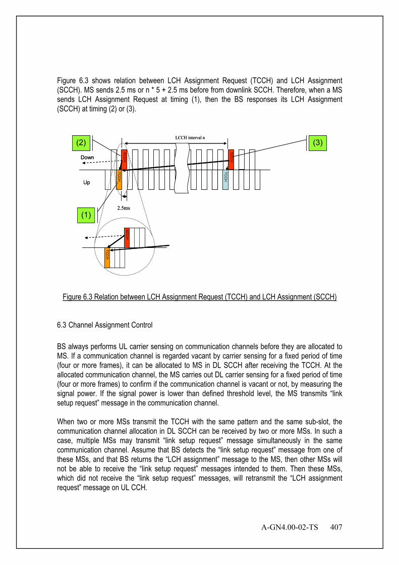
A-GN4.00-02-TS 407
Figure 6.3 shows relation between LCH Assignment Request (TCCH) and LCH Assignment (SCCH). MS sends 2.5 ms or n * 5 + 2.5 ms before from downlink SCCH. Therefore, when a MS sends LCH Assignment Request at timing (1), then the BS responses its LCH Assignment (SCCH) at timing (2) or (3).
Down
Up
SC
CH
SC
CH
TCC
H
TCC
H
2.5ms
LCCH interval n
TCC
H
SC
CH
(1)
(2) (3)
Down
Up
SC
CH
SC
CH
TCC
H
TCC
H
2.5ms
LCCH interval n
TCC
H
SC
CH
(1)
(2) (3)
Figure 6.3 Relation between LCH Assignment Request (TCCH) and LCH Assignment (SCCH)
6.3 Channel Assignment Control BS always performs UL carrier sensing on communication channels before they are allocated to MS. If a communication channel is regarded vacant by carrier sensing for a fixed period of time (four or more frames), it can be allocated to MS in DL SCCH after receiving the TCCH. At the allocated communication channel, the MS carries out DL carrier sensing for a fixed period of time (four or more frames) to confirm if the communication channel is vacant or not, by measuring the signal power. If the signal power is lower than defined threshold level, the MS transmits “link setup request” message in the communication channel. When two or more MSs transmit the TCCH with the same pattern and the same sub-slot, the communication channel allocation in DL SCCH can be received by two or more MSs. In such a case, multiple MSs may transmit “link setup request” message simultaneously in the same communication channel. Assume that BS detects the “link setup request” message from one of these MSs, and that BS returns the “LCH assignment” message to the MS, then other MSs will not be able to receive the “link setup request” messages intended to them. Then these MSs, which did not receive the “link setup request” messages, will retransmit the “LCH assignment request” message on UL CCH.
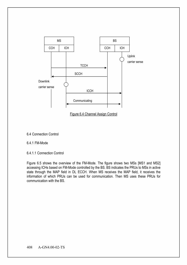
408 A-GN4.00-02-TS
MS
CCH ICH
BS
CCH ICH
TCCH
SCCH
Communicating
Uplink carrier sense
Downlink carrier sense
ICCH
Figure 6.4 Channel Assign Control
6.4 Connection Control 6.4.1 FM-Mode 6.4.1.1 Connection Control Figure 6.5 shows the overview of the FM-Mode. The figure shows two MSs [MS1 and MS2] accessing ICHs based on FM-Mode controlled by the BS. BS indicates the PRUs to MSs in active state through the MAP field in DL ECCH. When MS receives the MAP field, it receives the information of which PRUs can be used for communication. Then MS uses these PRUs for communication with the BS.
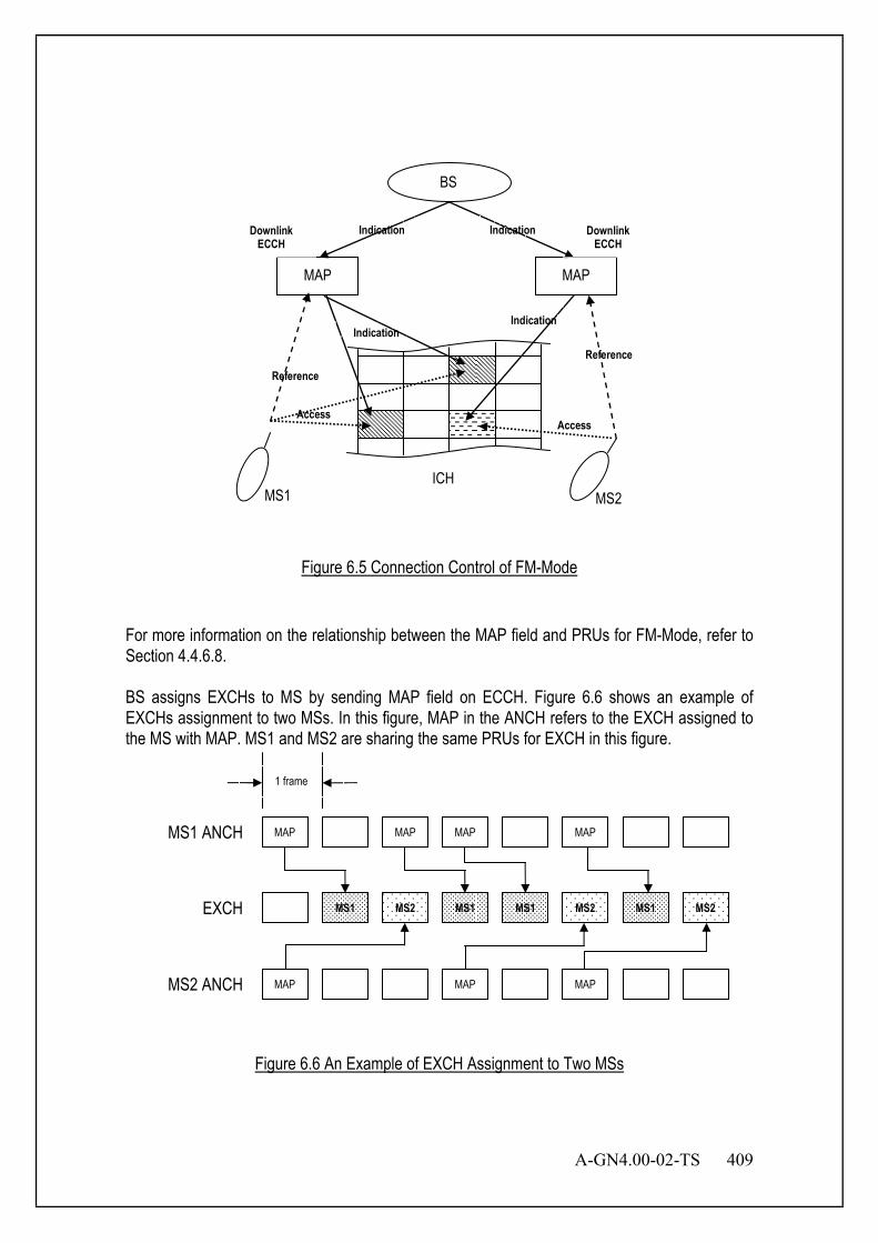
A-GN4.00-02-TS 409
MAP MAP
MS1 MS2
Indication
Indication Indication
Reference
Access
BS
Access
Reference
Indication
ICH
Downlink ECCH
Downlink ECCH
Figure 6.5 Connection Control of FM-Mode
For more information on the relationship between the MAP field and PRUs for FM-Mode, refer to Section 4.4.6.8. BS assigns EXCHs to MS by sending MAP field on ECCH. Figure 6.6 shows an example of EXCHs assignment to two MSs. In this figure, MAP in the ANCH refers to the EXCH assigned to the MS with MAP. MS1 and MS2 are sharing the same PRUs for EXCH in this figure.
Figure 6.6 An Example of EXCH Assignment to Two MSs
MAP MS1 ANCH
1 frame
MAP MAP MAP
EXCH MS1 MS2 MS1 MS1 MS2 MS1 MS2
MAP MS2 ANCH MAP MAP
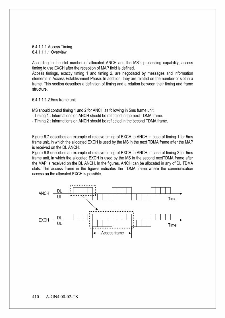
410 A-GN4.00-02-TS
6.4.1.1.1 Access Timing 6.4.1.1.1.1 Overview According to the slot number of allocated ANCH and the MS’s processing capability, access timing to use EXCH after the reception of MAP field is defined. Access timings, exactly timing 1 and timing 2, are negotiated by messages and information elements in Access Establishment Phase. In addition, they are related on the number of slot in a frame. This section describes a definition of timing and a relation between their timing and frame structure. 6.4.1.1.1.2 5ms frame unit MS should control timing 1 and 2 for ANCH as following in 5ms frame unit. - Timing 1 : Informations on ANCH should be reflected in the next TDMA frame. - Timing 2 : Informations on ANCH should be reflected in the second TDMA frame.
Figure 6.7 describes an example of relative timing of EXCH to ANCH in case of timing 1 for 5ms frame unit, in which the allocated EXCH is used by the MS in the next TDMA frame after the MAP is received on the DL ANCH. Figure 6.8 describes an example of relative timing of EXCH to ANCH in case of timing 2 for 5ms frame unit, in which the allocated EXCH is used by the MS in the second nextTDMA frame after the MAP is received on the DL ANCH. In the figures, ANCH can be allocated in any of DL TDMA slots. The access frame in the figures indicates the TDMA frame where the communication access on the allocated EXCH is possible.
ANCH DL UL
EXCH DL UL
Time
Time
Access frame
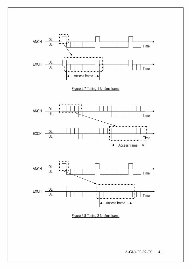
A-GN4.00-02-TS 411
Figure 6.7 Timing 1 for 5ms frame
Figure 6.8 Timing 2 for 5ms frame
ANCH DL UL
EXCH DL UL Time
Time
Access frame
ANCH DL UL
EXCH DL UL Time
Time
Access frame
ANCH DL UL
EXCH DL UL
Access frame
Time
Time

412 A-GN4.00-02-TS
6.4.1.1.1.3 2.5ms frame unit MS should control timing 1 and 2 for ANCH as following in 2.5ms frame unit. - Timing 1 : Informations on ANCH should be reflected in the second TDMA frame. - Timing 2 : Informations on ANCH should be reflected in the fourth TDMA frame. Figure 6.9 describes an example of relative timing of EXCH to ANCH in case of timing 1 for 2.5ms frame unit, in which the allocated EXCH is used by the MS in the second next TDMA frame after the MAP is received on the DL ANCH. Figure 6.10 describes an example of relative timing of EXCH to ANCH in case of timing 2 for 2.5ms frame unit, in which the allocated EXCH is used by the MS in the fourth next TDMA frame after the MAP is received on the DL ANCH. In the figures, ANCH can be allocated in any of DL TDMA slots. The access frame in the figures indicates the TDMA frame where the communication access on the allocated EXCH is possible.
Figure 6.9 Timing 1 for 2.5ms frame
ANCH DL UL
EXCH DL UL
Time
Time
Access frame
ANCH DL UL
EXCH DL UL
Time
Time
Access frame
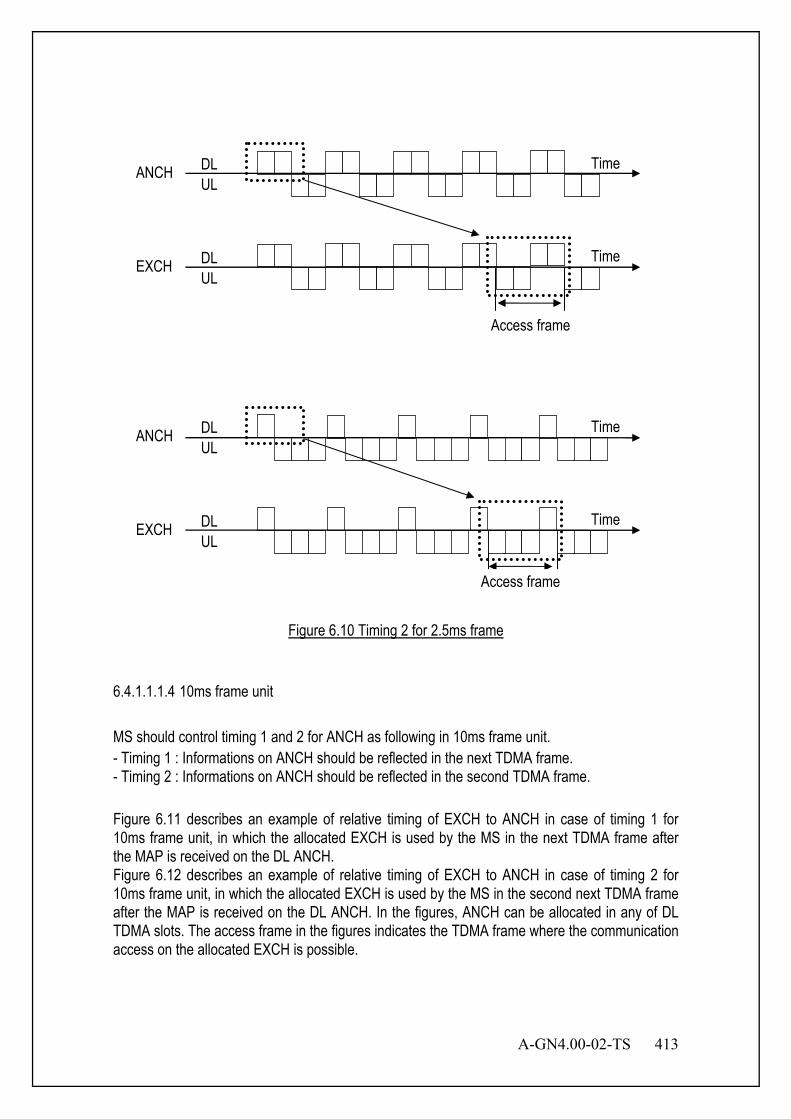
A-GN4.00-02-TS 413
Figure 6.10 Timing 2 for 2.5ms frame
6.4.1.1.1.4 10ms frame unit MS should control timing 1 and 2 for ANCH as following in 10ms frame unit. - Timing 1 : Informations on ANCH should be reflected in the next TDMA frame. - Timing 2 : Informations on ANCH should be reflected in the second TDMA frame. Figure 6.11 describes an example of relative timing of EXCH to ANCH in case of timing 1 for 10ms frame unit, in which the allocated EXCH is used by the MS in the next TDMA frame after the MAP is received on the DL ANCH. Figure 6.12 describes an example of relative timing of EXCH to ANCH in case of timing 2 for 10ms frame unit, in which the allocated EXCH is used by the MS in the second next TDMA frame after the MAP is received on the DL ANCH. In the figures, ANCH can be allocated in any of DL TDMA slots. The access frame in the figures indicates the TDMA frame where the communication access on the allocated EXCH is possible.
ANCH DL UL
EXCH DL UL
Time
Time
Access frame
ANCH DL UL
EXCH DL UL
Time
Time
Access frame
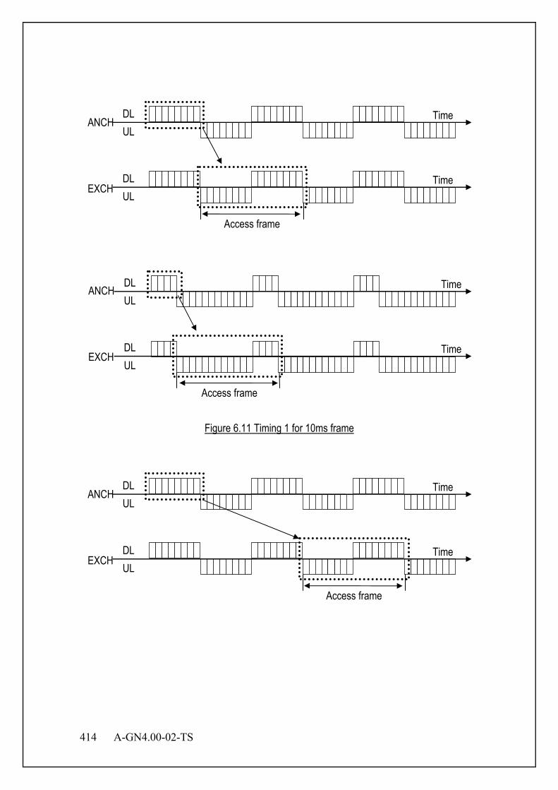
414 A-GN4.00-02-TS
Figure 6.11 Timing 1 for 10ms frame
ANCH DL UL
EXCH
Time
Access frame
DL UL
Time
ANCH DL UL
EXCH
Time
Access frame
DL UL
Time
ANCH DL UL
EXCH
Time
Access frame
DL UL
Time
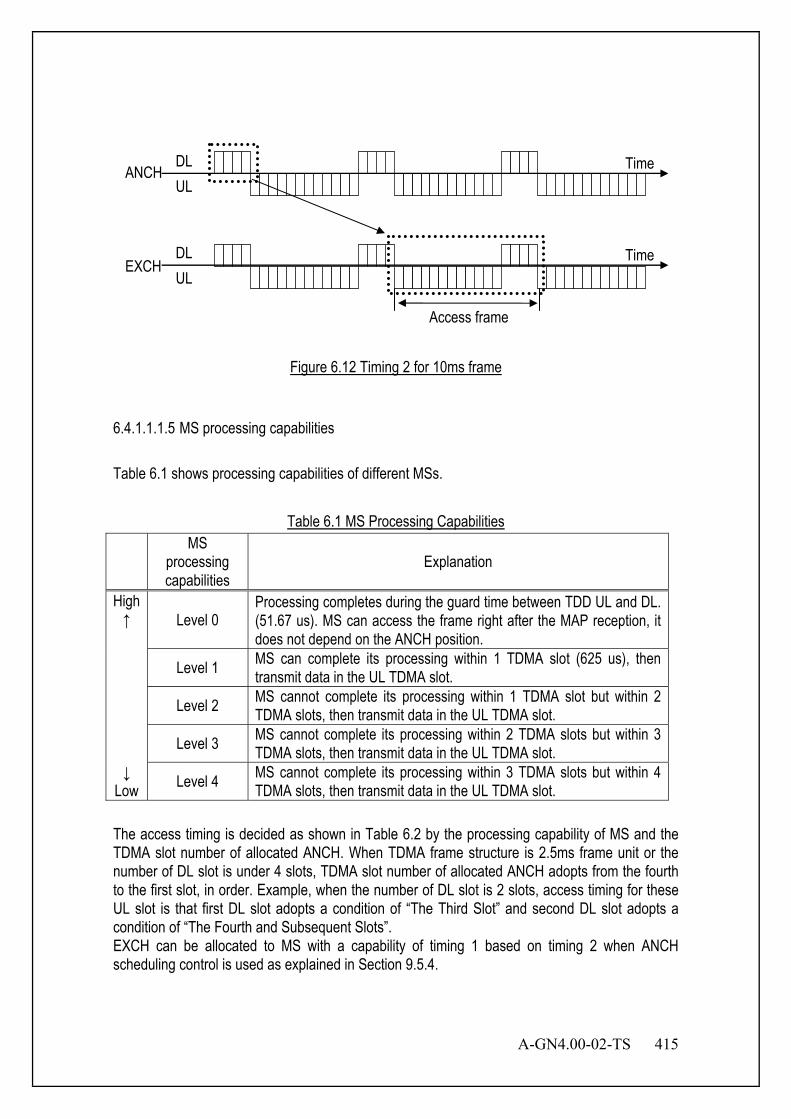
A-GN4.00-02-TS 415
Figure 6.12 Timing 2 for 10ms frame
6.4.1.1.1.5 MS processing capabilities Table 6.1 shows processing capabilities of different MSs.
Table 6.1 MS Processing Capabilities MS
processing capabilities
Explanation
High ↑ Level 0
Processing completes during the guard time between TDD UL and DL. (51.67 us). MS can access the frame right after the MAP reception, it does not depend on the ANCH position.
Level 1 MS can complete its processing within 1 TDMA slot (625 us), then transmit data in the UL TDMA slot.
Level 2 MS cannot complete its processing within 1 TDMA slot but within 2 TDMA slots, then transmit data in the UL TDMA slot.
Level 3 MS cannot complete its processing within 2 TDMA slots but within 3 TDMA slots, then transmit data in the UL TDMA slot.
↓ Low Level 4 MS cannot complete its processing within 3 TDMA slots but within 4
TDMA slots, then transmit data in the UL TDMA slot. The access timing is decided as shown in Table 6.2 by the processing capability of MS and the TDMA slot number of allocated ANCH. When TDMA frame structure is 2.5ms frame unit or the number of DL slot is under 4 slots, TDMA slot number of allocated ANCH adopts from the fourth to the first slot, in order. Example, when the number of DL slot is 2 slots, access timing for these UL slot is that first DL slot adopts a condition of “The Third Slot” and second DL slot adopts a condition of “The Fourth and Subsequent Slots”. EXCH can be allocated to MS with a capability of timing 1 based on timing 2 when ANCH scheduling control is used as explained in Section 9.5.4.
ANCH DL UL
EXCH
Time
Access frame
DL UL
Time

416 A-GN4.00-02-TS
Table 6.2 Access Timing
MS Processing Capability
The First Slot
The Second Slot
The Third Slot
The Fourth and Subsequent Slots
Level 0 Timing 1 Timing 1 Timing 1 Timing 1 Level 1 Timing 1 Timing 1 Timing 1 Timing 2 Level 2 Timing 1 Timing 1 Timing 2 Timing 2 Level 3 Timing 1 Timing 2 Timing 2 Timing 2 Level 4 Timing 2 Timing 2 Timing 2 Timing 2
6.4.1.1.2 Bandwidth Request by MS When MS requests bandwidth to the BS, MS informs the transmit data size to BS using the RCH field in UL ANCH. According to the requested data size from the MS, BS reserves the bandwidth and informs bandwidth allocation through the MAP field on the DL ANCH.
Figure 6.13 Bandwidth Allocation in Accordance with MS’s Request
6.4.1.1.3 DL EXCH Holding Duration DL EXCH will not be released during DL EXCH holding duration to avoid ANCH assignment by neighboring BSs, even when the DL EXCH is not used for information transmission. Figure 6.14 shows the relationship between the valid EXCH transmission and DL EXCH holding duration.
RCH
ANCH
EXCH
DL
UL
DL
UL
MAP
Time
Time

A-GN4.00-02-TS 417
Figure 6.14 Maintenance Condition of DL EXCH
The hatched TDMA frames indicate EXCH which is used for information transfer. The plain frames indicate DL EXCH which is not used for information transfer to any MSs in active state. In these frames, BS may send idle burst on DL EXCH. BS counts the number of frames from the last reception or transmission. When the count reaches DL EXCH holding duration, BS releases the allocated EXCH. BS will reset the count if data has been received or transmitted within DL EXCH holding duration. 6.4.1.2 Channel Selection BS always carries out UL carrier sensing for unused PRUs in the entire bandwidth. The result of carrier sensing information will be used for channel selection. 6.4.1.2.1 Vacant PRU Judgment by UL Carrier Sensing UL carrier sensing is carried out for UL EXCH monitoring time. Maximum value of UL carrier sensing will be used for the judgment of the vacant PRUs. UL EXCH monitoring time should be longer than DL EXCH holding duration. Based on this relationship, the neighbor BSs will avoid using the PRUs which are occupied. BS should monitor continuously for the UL EXCH monitoring time on all PRUs which the BS does not use in order to decide whether PRUs are vacant or occupied by other BSs. If the UL EXCH monitoring time is shorter than DL EXCH holding duration, then the neighbor BSs may regard a PRU which is actually occupied by EXCH, as a free PRU. Collisions will be caused if PRU is allocated to other MSs. Therefore, the UL EXCH monitoring time should be longer than the DL EXCH holding duration.
Figure 6.15 EXCH Release Timing
DL
UL Time
DL EXCH holding duration Release EXCHs
DL
UL Time
Release EXCHs
Less than DL EXCH holding duration
DL EXCH holding duration
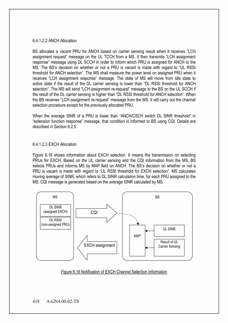
418 A-GN4.00-02-TS
6.4.1.2.2 ANCH Allocation BS allocates a vacant PRU for ANCH based on carrier sensing result when it receives ”LCH assignment request” message on the UL TCCH from a MS. It then transmits “LCH assignment response” message using DL SCCH in order to inform which PRU is assigned for ANCH to the MS. The BS’s decision on whether or not a PRU is vacant is made with regard to “UL RSSI threshold for ANCH selection”. The MS shall measure the power level on assigned PRU when it receives “LCH assignment response” message. The state of MS will move from idle state to active state if the result of the DL carrier sensing is lower than “DL RSSI threshold for ANCH selection”. The MS will send “LCH assignment re-request” message to the BS on the UL SCCH if the result of the DL carrier sensing is higher than “DL RSSI threshold for ANCH selection”. When the BS receives “LCH assignment re-request” message from the MS, it will carry out the channel selection procedure except for the previously allocated PRU. When the average SINR of a PRU is lower than “ANCH/CSCH switch DL SINR threshold” in “extension function response” message, that condition is informed to BS using CQI. Details are described in Section 8.2.5. 6.4.1.2.3 EXCH Allocation Figure 6.16 shows information about EXCH selection. It means the transmission on selecting PRUs for EXCH. Based on the UL carrier sensing and the CQI information from the MS, BS selects PRUs and informs MS by MAP field on ANCH. The BS’s decision on whether or not a PRU is vacant is made with regard to “UL RSSI threshold for EXCH selection”. MS calculates moving average of SINR, which refers to DL SINR calculation time, for each PRU assigned to the MS. CQI message is generated based on the average SINR calculated by MS.
Figure 6.16 Notification of EXCH Channel Selection Information
BS MS
DL SINR (assigned EXCH) CQI
EXCH assignment
MAP
UL SINR
Result of UL Carrier Sensing
DL RSSI (non-assigned PRU)

A-GN4.00-02-TS 419
The result of UL carrier sensing is used as the UL radio information when BS allocates vacant PRUs. Instead of allocating low-quality PRUs for the MS, BS will replace these with the higher-quality PRUs based on the CQI information. PRU, of which the UL carrier sensing result is lower than “UL RSSI threshold for EXCH selection”, is selected as a candidate PRU for allocation. PRU refused by CQI is not allocated by BS for the MS. When the vacant PRU is used, judgment of vacancy will be done by making use of result of the UL carrier sensing as shown in Section 6.4.1.2.1. BS calculates moving average of SINR, which refers to UL SINR calculation time, for every used PRU. When BS selects active PRU, it prioritizes PRUs which have high average SINR values. The refused PRUs notified in the CQI information are excluded from the selection. 6.4.2 QS-Mode 6.4.2.1 Channel Selection BS always carries out UL carrier sensing for unused PRUs in the entire bandwidth. The result of carrier sensing information will be used for channel selection. 6.4.2.1.1 CSCH Allocation When BS receives “LCH assignment request” message from the MS on the UL TCCH, it will allocate a vacant PRU and sends “LCH assignment response” message to MS on DL SCCH. The BS’s decision on whether or not a PRU is vacant is made with regard to “UL RSSI threshold for CSCH selection”. DL carrier sensing will be carried out on the designated PRU when MS receives “LCH assignment response” message. If the result of the DL carrier sensing is lower than “DL RSSI threshold for CSCH selection”, the state of MS will move from idle state to active state. If the result of the DL carrier sensing is higher than “DL RSSI threshold for CSCH selection”, the MS will send “LCH assignment re-request” message to the BS on the UL SCCH. BS will carry out the channel selection procedure except for the previously allocated PRU when the BS receives “LCH assignment re-request” message. When the average SINR of a PRU is lower than “ANCH/CSCH switch DL SINR threshold” in “extension function response” message, that condition is informed to BS by CQI. Details are described in Section 8.2.5.

420 A-GN4.00-02-TS
6.5 Radio State Management Figure 6.17 describes the radio states of MS. MS has three states. They are idle state, active state and sleep state.
Idle
Active Sleep
Release Session
Re-establish connection
Release Connection
(keep session)
Initiate connection
Release Connection
(release session)
Figure 6.17 State Transition of MS
Table 6.3 States of MS
State Name Radio Connection State
QCS State State of MS
Idle Nothing Nothing MS is waiting for paging messages. Active One or more One or more Data exchange with BS using ICH. Sleep Nothing One or more MS keeps QCS, but no ICH is established.

A-GN4.00-02-TS 421
6.5.1 Idle State Idle state is a state without radio connection and QCS. In idle state, MS receives its own “paging” messages only on its PCH group. In time of incoming call or out-going call, MS in idle state is assigned an ICH from BS by SCCH and triggered to active state. The figure shows the sequence of an MS to move from idle state to active state.
MS BS
TCCH
SCCH
Communicating
ICCH
Idle
Active
ICCH
Figure 6.18 Move to Active State
MS transmits “LCH assignment request” message on TCCH to request ICH allocation. BS selects the vacant PRU from the result of the UL carrier sensing and informs the number of the allocated ICH through “LCH assignment response” message on DL SCCH. The BS’s decision on whether or not a PRU is vacant is made with regard to “UL RSSI threshold for ICCH selection”. MS carries out the DL carrier sensing on the specified PRU when it receives “LCH assignment response” message. MS will start transmission to the BS on this PRU if the result of the carrier sensing is lower than “DL RSSI threshold for ICCH selection”. Then the PRU is used as ICCH. It is considered that the radio connection between MS and BS is established when BS receives UL ICCH. MS will then perform initial radio settings to establish QCS and move itself to active state.

422 A-GN4.00-02-TS
6.5.2 Active State Active state is a state with one or more than one radio connections and QCSs. In this state, MS can have one or more than one radio connections and QCSs. MS and BS can exchange data using the radio connections. BS supervises data transmission and the reception. If there is no data transmission and reception during sleep transfer time, BS releases all radio connections but holds QCS connections, and the state of MS moves to sleep state. The change from active state to sleep is executed according to the following procedure.
MS BS
Connection release (sleep state )
Connection release acknowledge
Tx Off Tx Off
Sleep
Active
Figure 6.19 Move to Sleep State
When MS transmits UL data or receives DL data, data communication supervision timer is started. If there is data transmission or reception before timer expires, the timer will be restarted automatically. When data is not transmitted and received during sleep transfer time, data communication supervision timer will expire, and MS will send “connection release (sleep state)” message. BS transmits “connection release acknowledge” message when it receives the message. MS and BS will then release radio connection, and move to sleep state as shown in Figure 6.19.
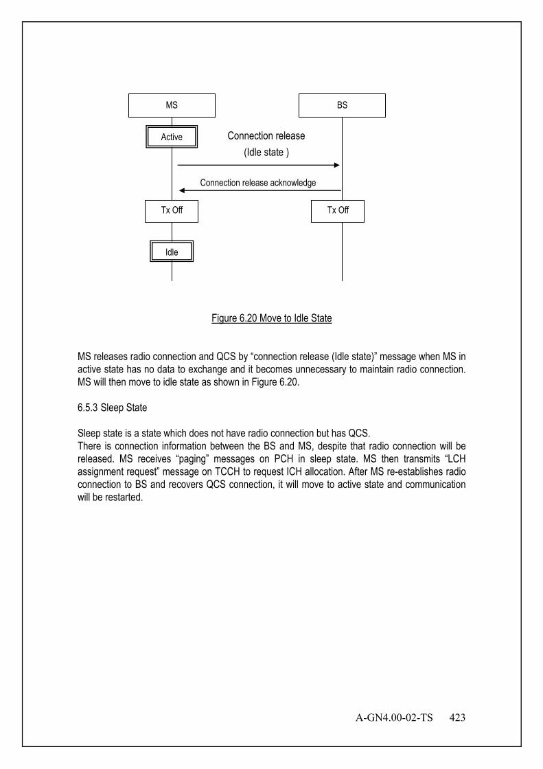
A-GN4.00-02-TS 423
MS BS
Connection release (Idle state )
Connection release acknowledge
Tx Off Tx Off
Idle
Active
Figure 6.20 Move to Idle State
MS releases radio connection and QCS by “connection release (Idle state)” message when MS in active state has no data to exchange and it becomes unnecessary to maintain radio connection. MS will then move to idle state as shown in Figure 6.20. 6.5.3 Sleep State Sleep state is a state which does not have radio connection but has QCS. There is connection information between the BS and MS, despite that radio connection will be released. MS receives “paging” messages on PCH in sleep state. MS then transmits “LCH assignment request” message on TCCH to request ICH allocation. After MS re-establishes radio connection to BS and recovers QCS connection, it will move to active state and communication will be restarted.

424 A-GN4.00-02-TS
MS BS
TCCH
SCCH
Communicating
ICCH
Sleep
Active
ICCH
PCH
Figure 6.21 Recovery from Sleep State by DL Data Generation
When it becomes unnecessary for MS to maintain QCS, it releases QCS and moves itself to idle state. 6.6 Optional Radio State Management A MS is in Active state when an radio connection has been established. If this is not the case, i.e. no radio connection is established, the MS is in IDLE state.
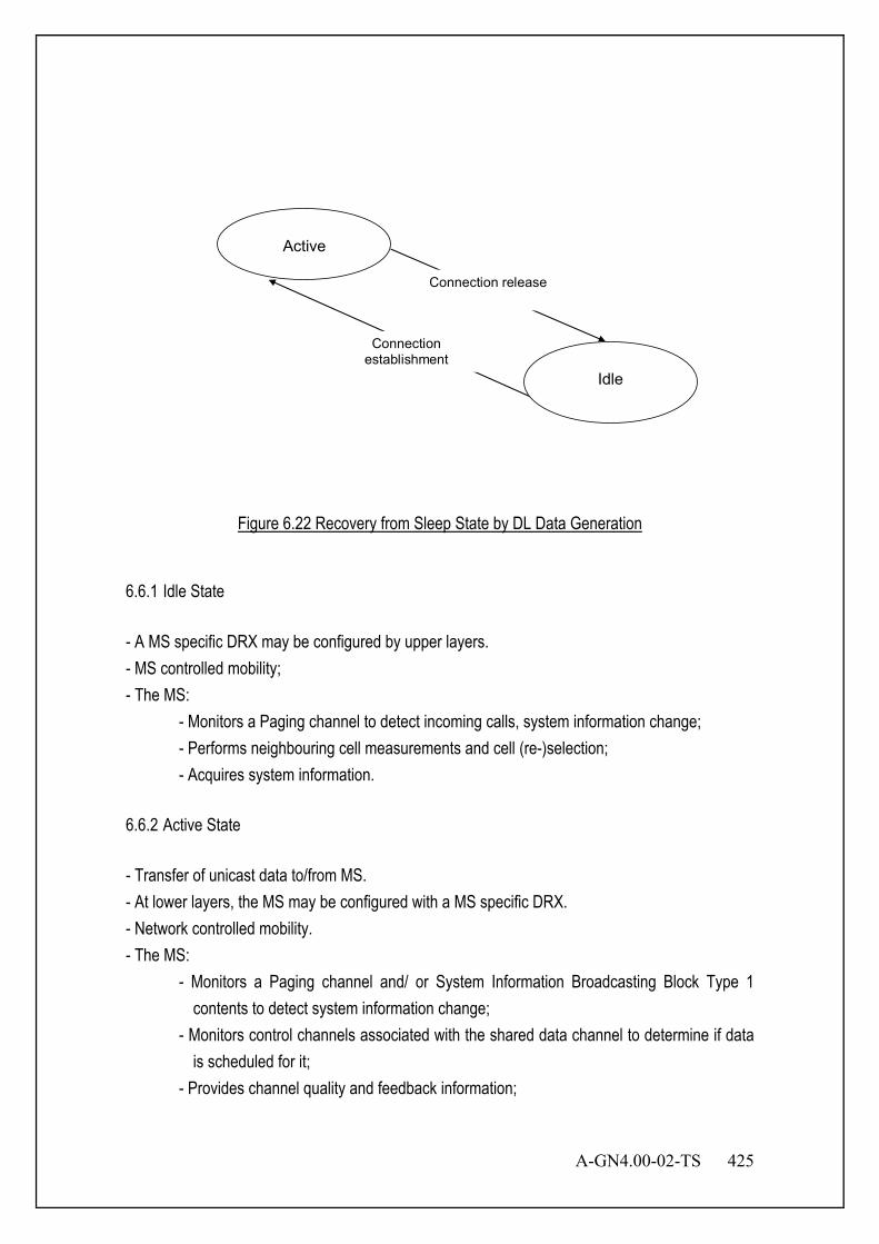
A-GN4.00-02-TS 425
Connection release
Connection establishment
Active
Idle
Figure 6.22 Recovery from Sleep State by DL Data Generation
6.6.1 Idle State - A MS specific DRX may be configured by upper layers. - MS controlled mobility; - The MS:
- Monitors a Paging channel to detect incoming calls, system information change; - Performs neighbouring cell measurements and cell (re-)selection; - Acquires system information.
6.6.2 Active State - Transfer of unicast data to/from MS. - At lower layers, the MS may be configured with a MS specific DRX. - Network controlled mobility. - The MS:
- Monitors a Paging channel and/ or System Information Broadcasting Block Type 1 contents to detect system information change;
- Monitors control channels associated with the shared data channel to determine if data is scheduled for it;
- Provides channel quality and feedback information;

426 A-GN4.00-02-TS
- Performs neighbouring cell measurements and measurement reporting; - Acquires system information.
6.7 ICH continuation transmission ICH continuation transmission is expected to improve linkbudget. The receiver, both of BS and MS, receives same ANCH and EXCH during several frames. The control of this function as start and stop can be required by both of BS and MS. The information elements for this function are added in ANCH/CSCH Switching Request, ANCH/CSCH Switching Indication and ANCH/CSCH Switching Re-request. Figure 6.23 shows to ICH continuation transmission is switched from inactive to active by each MS and BS.
ANCH/CSCH Switching Request ANCH/CSCH Switching Indication
ANCH/CSCH Switching Indication ANCH/CSCH Switching Confirmation
ANCH/CSCH Switching Confirmation
MS BSMS BS
Normal transmission
ICH Continuation Transmission
Normal transmission
ICH Continuation Transmission
Figure 6.23 Control ICH Continuation transmission
6.8 Optional Random access procedure The MS Access and establish the link to the network by optional Random Access (RA) procedure. There are four messages for four steps of RA procedure and one message maps on one step. The contention based random access procedure is described below: The four steps of the contention based random access procedures are: 1) Random Access Sequence on ATCCH in uplink: - There are two possible groups defined and one is optional. If both groups are
configured the size of message 3 and the pathloss are used to determine which group a access sequence is selected from. The group to which a access sequence belongs provides an indication of the size of the message 3 and the radio conditions at the MS.

A-GN4.00-02-TS 427
The access sequence group information along with the necessary thresholds are broadcast on system information.
2) Random Access Response generated by MSL1 on ADSCH: - Semi-synchronous with message 1; - No HARQ; - Addressed to RA-MSID on ADECCH; - Conveys at least RA access sequence identifier, Timing Alignment information, initial
UL grant and assignment of Temporary C-MSID (which may or may not be made permanent upon Contention Resolution);
- Intended for a variable number of MSs in one ADSCH message. 3) First scheduled UL transmission on AUSCH: - Uses HARQ; - Size of the transport blocks depends on the UL grant conveyed in step 2 and is at least
80 bits. - For initial access: - Conveys the high layer Connection Request generated by the high layer layer and
transmitted via ACCCH - For high layer Connection Re-establishment procedure:
- Conveys the high layer Connection Re-establishment Request generated by the high layer layer and transmitted via ACCCH;
- After handover, in the target cell: - Conveys the ciphered and integrity protected high layer Handover Confirm generated
by the high layer layer and transmitted via ADCCH;
- Conveys the C-MSID of the MS (which was allocated via the Handover Command);
- For other events: - Conveys at least the C-MSID of the MS.
4) Contention Resolution on DL: - Not synchronised with message 3; - HARQ is supported; - Addressed to:
- The Temporary C-MSID on ADECCH for initial access and after radio link failure;
- The C-MSID on ADECCH for MS in high layer_CONNECTED;
- HARQ feedback is transmitted only by the MS which detects its own MS identity, as
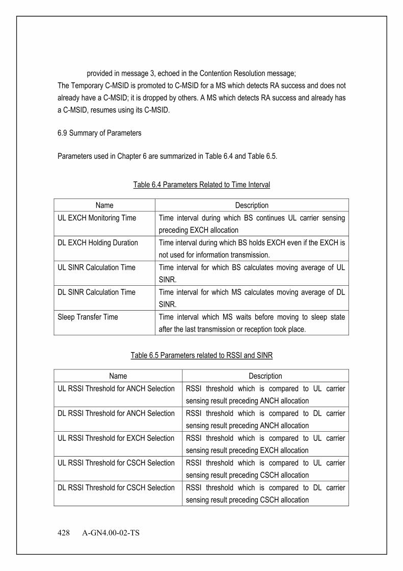
428 A-GN4.00-02-TS
provided in message 3, echoed in the Contention Resolution message; The Temporary C-MSID is promoted to C-MSID for a MS which detects RA success and does not already have a C-MSID; it is dropped by others. A MS which detects RA success and already has a C-MSID, resumes using its C-MSID. 6.9 Summary of Parameters Parameters used in Chapter 6 are summarized in Table 6.4 and Table 6.5.
Table 6.4 Parameters Related to Time Interval
Name Description UL EXCH Monitoring Time Time interval during which BS continues UL carrier sensing
preceding EXCH allocation DL EXCH Holding Duration Time interval during which BS holds EXCH even if the EXCH is
not used for information transmission. UL SINR Calculation Time Time interval for which BS calculates moving average of UL
SINR. DL SINR Calculation Time Time interval for which MS calculates moving average of DL
SINR. Sleep Transfer Time Time interval which MS waits before moving to sleep state
after the last transmission or reception took place.
Table 6.5 Parameters related to RSSI and SINR
Name Description UL RSSI Threshold for ANCH Selection RSSI threshold which is compared to UL carrier
sensing result preceding ANCH allocation DL RSSI Threshold for ANCH Selection RSSI threshold which is compared to DL carrier
sensing result preceding ANCH allocation UL RSSI Threshold for EXCH Selection RSSI threshold which is compared to UL carrier
sensing result preceding EXCH allocation UL RSSI Threshold for CSCH Selection RSSI threshold which is compared to UL carrier
sensing result preceding CSCH allocation DL RSSI Threshold for CSCH Selection RSSI threshold which is compared to DL carrier
sensing result preceding CSCH allocation
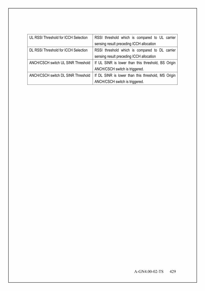
A-GN4.00-02-TS 429
UL RSSI Threshold for ICCH Selection RSSI threshold which is compared to UL carrier sensing result preceding ICCH allocation
DL RSSI Threshold for ICCH Selection RSSI threshold which is compared to DL carrier sensing result preceding ICCH allocation
ANCH/CSCH switch UL SINR Threshold If UL SINR is lower than this threshold, BS Origin ANCH/CSCH switch is triggered.
ANCH/CSCH switch DL SINR Threshold If DL SINR is lower than this threshold, MS Origin ANCH/CSCH switch is triggered.
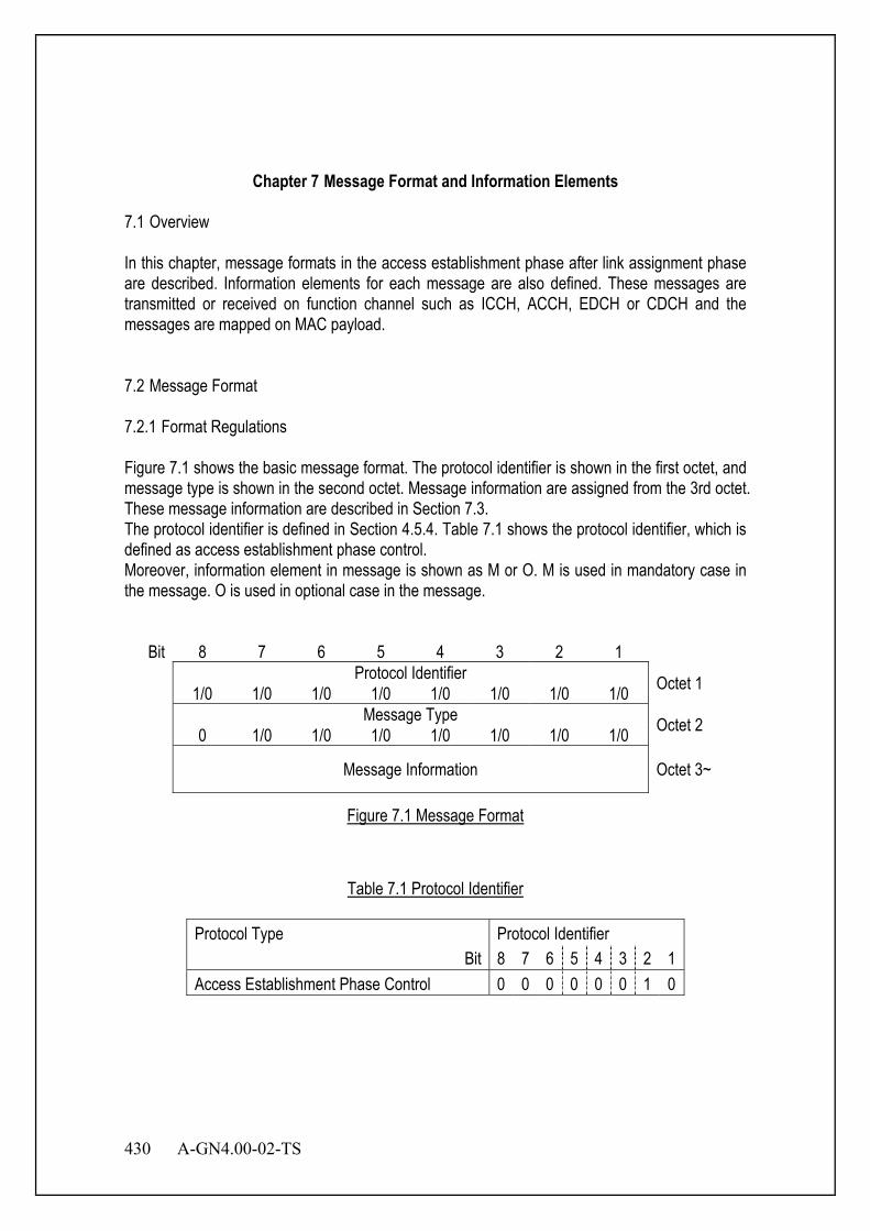
430 A-GN4.00-02-TS
Chapter 7 Message Format and Information Elements
7.1 Overview In this chapter, message formats in the access establishment phase after link assignment phase are described. Information elements for each message are also defined. These messages are transmitted or received on function channel such as ICCH, ACCH, EDCH or CDCH and the messages are mapped on MAC payload. 7.2 Message Format 7.2.1 Format Regulations Figure 7.1 shows the basic message format. The protocol identifier is shown in the first octet, and message type is shown in the second octet. Message information are assigned from the 3rd octet. These message information are described in Section 7.3. The protocol identifier is defined in Section 4.5.4. Table 7.1 shows the protocol identifier, which is defined as access establishment phase control. Moreover, information element in message is shown as M or O. M is used in mandatory case in the message. O is used in optional case in the message.
Bit 8 7 6 5 4 3 2 1 Protocol Identifier Octet 1 1/0 1/0 1/0 1/0 1/0 1/0 1/0 1/0 Message Type Octet 2 0 1/0 1/0 1/0 1/0 1/0 1/0 1/0
Message Information Octet 3~
Figure 7.1 Message Format
Table 7.1 Protocol Identifier
Protocol Type Protocol Identifier Bit 8 7 6 5 4 3 2 1
Access Establishment Phase Control 0 0 0 0 0 0 1 0
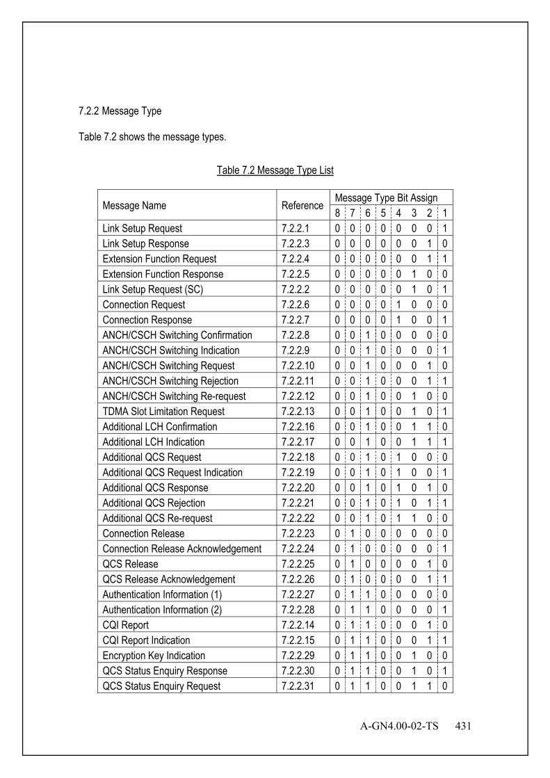
A-GN4.00-02-TS 431
7.2.2 Message Type Table 7.2 shows the message types.
Table 7.2 Message Type List
Message Name Reference Message Type Bit Assign 8 7 6 5 4 3 2 1
Link Setup Request 7.2.2.1 0 0 0 0 0 0 0 1 Link Setup Response 7.2.2.3 0 0 0 0 0 0 1 0 Extension Function Request 7.2.2.4 0 0 0 0 0 0 1 1 Extension Function Response 7.2.2.5 0 0 0 0 0 1 0 0 Link Setup Request (SC) 7.2.2.2 0 0 0 0 0 1 0 1 Connection Request 7.2.2.6 0 0 0 0 1 0 0 0 Connection Response 7.2.2.7 0 0 0 0 1 0 0 1 ANCH/CSCH Switching Confirmation 7.2.2.8 0 0 1 0 0 0 0 0 ANCH/CSCH Switching Indication 7.2.2.9 0 0 1 0 0 0 0 1 ANCH/CSCH Switching Request 7.2.2.10 0 0 1 0 0 0 1 0 ANCH/CSCH Switching Rejection 7.2.2.11 0 0 1 0 0 0 1 1 ANCH/CSCH Switching Re-request 7.2.2.12 0 0 1 0 0 1 0 0 TDMA Slot Limitation Request 7.2.2.13 0 0 1 0 0 1 0 1 Additional LCH Confirmation 7.2.2.16 0 0 1 0 0 1 1 0 Additional LCH Indication 7.2.2.17 0 0 1 0 0 1 1 1 Additional QCS Request 7.2.2.18 0 0 1 0 1 0 0 0 Additional QCS Request Indication 7.2.2.19 0 0 1 0 1 0 0 1 Additional QCS Response 7.2.2.20 0 0 1 0 1 0 1 0 Additional QCS Rejection 7.2.2.21 0 0 1 0 1 0 1 1 Additional QCS Re-request 7.2.2.22 0 0 1 0 1 1 0 0 Connection Release 7.2.2.23 0 1 0 0 0 0 0 0 Connection Release Acknowledgement 7.2.2.24 0 1 0 0 0 0 0 1 QCS Release 7.2.2.25 0 1 0 0 0 0 1 0 QCS Release Acknowledgement 7.2.2.26 0 1 0 0 0 0 1 1 Authentication Information (1) 7.2.2.27 0 1 1 0 0 0 0 0 Authentication Information (2) 7.2.2.28 0 1 1 0 0 0 0 1 CQI Report 7.2.2.14 0 1 1 0 0 0 1 0 CQI Report Indication 7.2.2.15 0 1 1 0 0 0 1 1 Encryption Key Indication 7.2.2.29 0 1 1 0 0 1 0 0 QCS Status Enquiry Response 7.2.2.30 0 1 1 0 0 1 0 1 QCS Status Enquiry Request 7.2.2.31 0 1 1 0 0 1 1 0
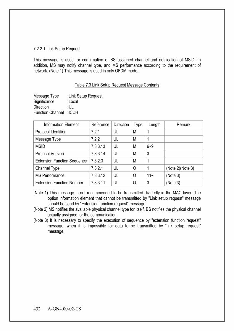
432 A-GN4.00-02-TS
7.2.2.1 Link Setup Request This message is used for confirmation of BS assigned channel and notification of MSID. In addition, MS may notify channel type, and MS performance according to the requirement of network. (Note 1) This message is used in only OFDM mode.
Table 7.3 Link Setup Request Message Contents
Message Type : Link Setup Request Significance : Local Direction : UL Function Channel : ICCH
Information Element Reference Direction Type Length Remark Protocol Identifier 7.2.1 UL M 1 Message Type 7.2.2 UL M 1 MSID 7.3.3.13 UL M 6~9 Protocol Version 7.3.3.14 UL M 3 Extension Function Sequence 7.3.2.3 UL M 1 Channel Type 7.3.2.1 UL O 1 (Note 2)(Note 3) MS Performance 7.3.3.12 UL O 11~ (Note 3) Extension Function Number 7.3.3.11 UL O 3 (Note 3)
(Note 1) This message is not recommended to be transmitted dividedly in the MAC layer. The option information element that cannot be transmitted by "Link setup request" message should be send by "Extension function request" message.
(Note 2) MS notifies the available physical channel type for itself. BS notifies the physical channel actually assigned for the communication.
(Note 3) It is necessary to specify the execution of sequence by "extension function request" message, when it is impossible for data to be transmitted by “link setup request” message.

A-GN4.00-02-TS 433
7.2.2.2 Link Setup Request (SC) This message is used for confirmation of BS assigned channel and notification of MSID. This message is used in SC mode. Response message for the Link Setup Request (SC) is same as OFDM.
Table 7.4 Link Setup Request (SC) Message Contents
Message Type : Link Setup Request (SC) Significance : Local Direction : UL Function Channel : ICCH
Information Element Reference Direction Type Length Remark Protocol Identifier 7.2.1 UL M 1 Message Type 7.2.2 UL M 1 MSID (SC) 7.3.3.23 UL M 5/6/8
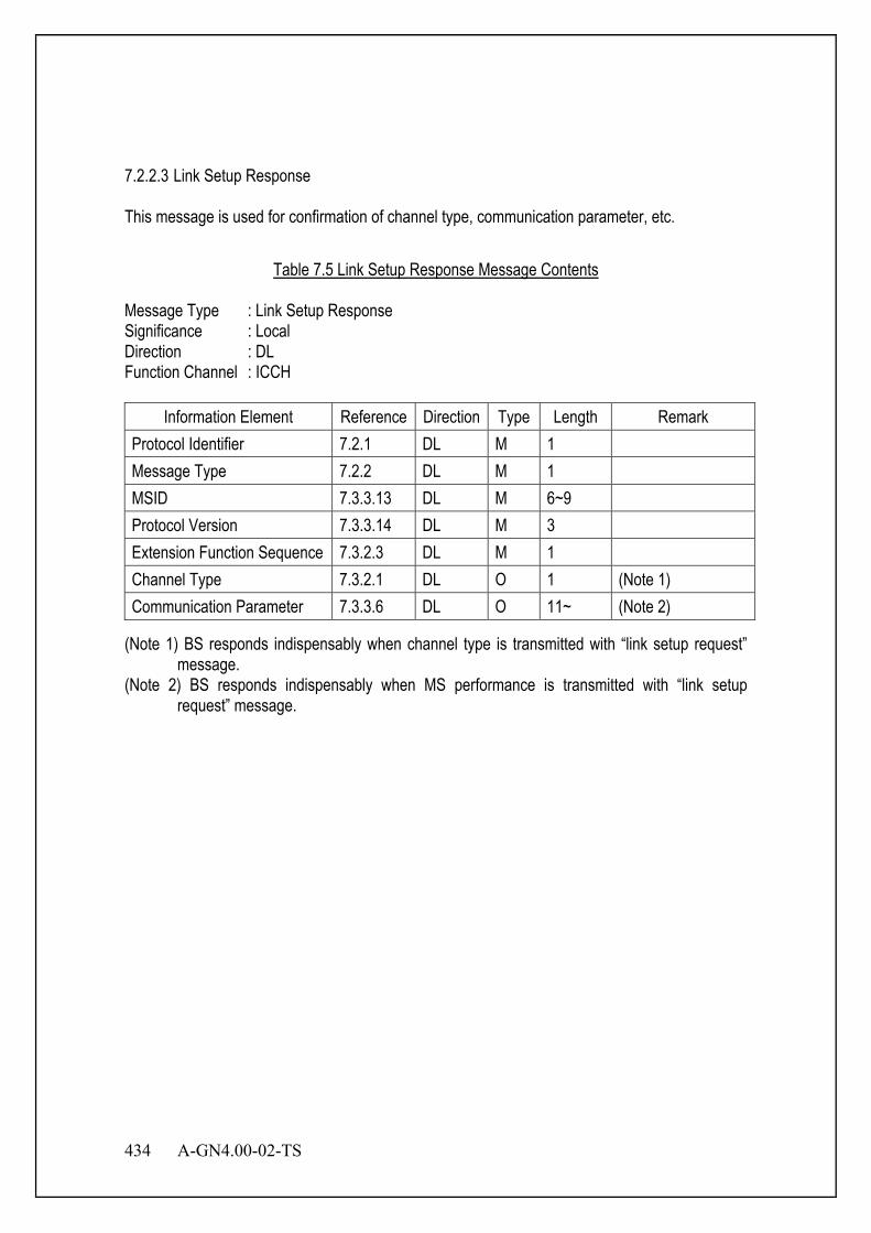
434 A-GN4.00-02-TS
7.2.2.3 Link Setup Response This message is used for confirmation of channel type, communication parameter, etc.
Table 7.5 Link Setup Response Message Contents
Message Type : Link Setup Response Significance : Local Direction : DL Function Channel : ICCH
Information Element Reference Direction Type Length Remark Protocol Identifier 7.2.1 DL M 1 Message Type 7.2.2 DL M 1 MSID 7.3.3.13 DL M 6~9 Protocol Version 7.3.3.14 DL M 3 Extension Function Sequence 7.3.2.3 DL M 1 Channel Type 7.3.2.1 DL O 1 (Note 1) Communication Parameter 7.3.3.6 DL O 11~ (Note 2)
(Note 1) BS responds indispensably when channel type is transmitted with “link setup request” message.
(Note 2) BS responds indispensably when MS performance is transmitted with “link setup request” message.
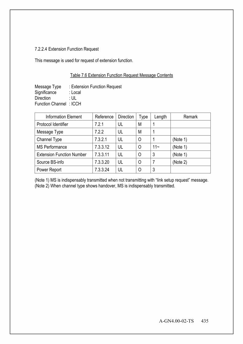
A-GN4.00-02-TS 435
7.2.2.4 Extension Function Request This message is used for request of extension function.
Table 7.6 Extension Function Request Message Contents
Message Type : Extension Function Request Significance : Local Direction : UL Function Channel : ICCH
Information Element Reference Direction Type Length Remark Protocol Identifier 7.2.1 UL M 1 Message Type 7.2.2 UL M 1 Channel Type 7.3.2.1 UL O 1 (Note 1) MS Performance 7.3.3.12 UL O 11~ (Note 1) Extension Function Number 7.3.3.11 UL O 3 (Note 1) Source BS-info 7.3.3.20 UL O 7 (Note 2) Power Report 7.3.3.24 UL O 3
(Note 1) MS is indispensably transmitted when not transmitting with “link setup request” message. (Note 2) When channel type shows handover, MS is indispensably transmitted.
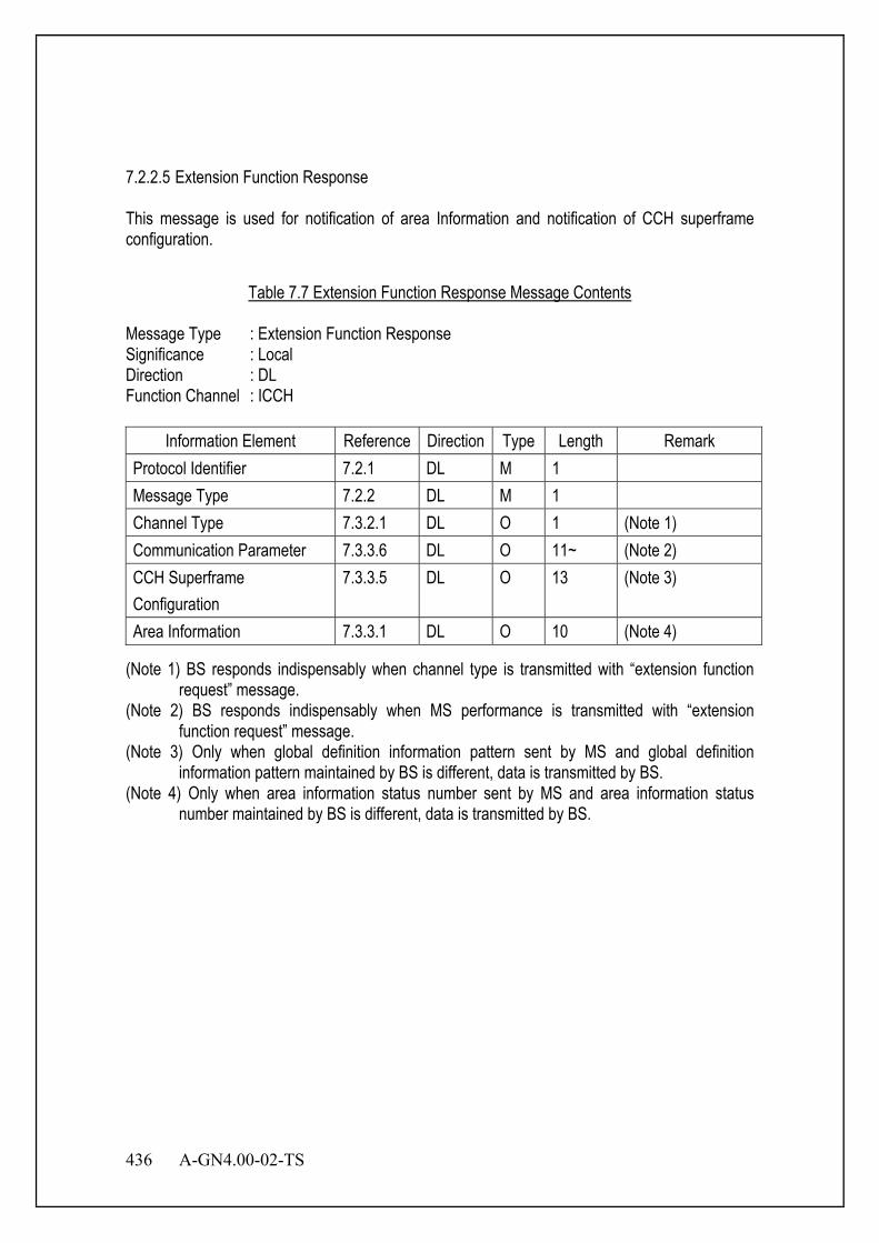
436 A-GN4.00-02-TS
7.2.2.5 Extension Function Response This message is used for notification of area Information and notification of CCH superframe configuration.
Table 7.7 Extension Function Response Message Contents
Message Type : Extension Function Response Significance : Local Direction : DL Function Channel : ICCH
Information Element Reference Direction Type Length Remark Protocol Identifier 7.2.1 DL M 1 Message Type 7.2.2 DL M 1 Channel Type 7.3.2.1 DL O 1 (Note 1) Communication Parameter 7.3.3.6 DL O 11~ (Note 2) CCH Superframe Configuration
7.3.3.5 DL O 13 (Note 3)
Area Information 7.3.3.1 DL O 10 (Note 4)
(Note 1) BS responds indispensably when channel type is transmitted with “extension function request” message.
(Note 2) BS responds indispensably when MS performance is transmitted with “extension function request” message.
(Note 3) Only when global definition information pattern sent by MS and global definition information pattern maintained by BS is different, data is transmitted by BS.
(Note 4) Only when area information status number sent by MS and area information status number maintained by BS is different, data is transmitted by BS.
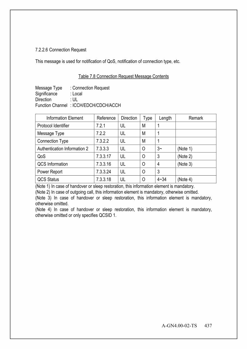
A-GN4.00-02-TS 437
7.2.2.6 Connection Request This message is used for notification of QoS, notification of connection type, etc.
Table 7.8 Connection Request Message Contents
Message Type : Connection Request Significance : Local Direction : UL Function Channel : ICCH/EDCH/CDCH/ACCH
Information Element Reference Direction Type Length Remark Protocol Identifier 7.2.1 UL M 1 Message Type 7.2.2 UL M 1 Connection Type 7.3.2.2 UL M 1 Authentication Information 2 7.3.3.3 UL O 3~ (Note 1) QoS 7.3.3.17 UL O 3 (Note 2) QCS Information 7.3.3.16 UL O 4 (Note 3) Power Report 7.3.3.24 UL O 3 QCS Status 7.3.3.18 UL O 4~34 (Note 4)
(Note 1) In case of handover or sleep restoration, this information element is mandatory. (Note 2) In case of outgoing call, this information element is mandatory, otherwise omitted. (Note 3) In case of handover or sleep restoration, this information element is mandatory, otherwise omitted. (Note 4) In case of handover or sleep restoration, this information element is mandatory, otherwise omitted or only specifies QCSID 1.
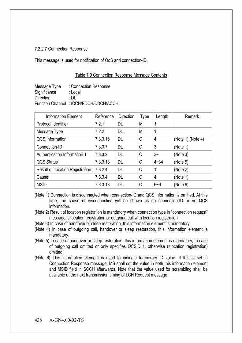
438 A-GN4.00-02-TS
7.2.2.7 Connection Response This message is used for notification of QoS and connection-ID.
Table 7.9 Connection Response Message Contents
Message Type : Connection Response Significance : Local Direction : DL Function Channel : ICCH/EDCH/CDCH/ACCH
Information Element Reference Direction Type Length Remark Protocol Identifier 7.2.1 DL M 1 Message Type 7.2.2 DL M 1 QCS Information 7.3.3.16 DL O 4 (Note 1) (Note 4) Connection-ID 7.3.3.7 DL O 3 (Note 1) Authentication Information 1 7.3.3.2 DL O 3~ (Note 3) QCS Status 7.3.3.18 DL O 4~34 (Note 5) Result of Location Registration 7.3.2.4 DL O 1 (Note 2) Cause 7.3.3.4 DL O 4 (Note 1) MSID 7.3.3.13 DL O 6~9 (Note 6)
(Note 1) Connection is disconnected when connection-ID and QCS information is omitted. At this time, the cause of disconnection will be shown as no connection-ID or no QCS information.
(Note 2) Result of location registration is mandatory when connection type in “connection request” message is location registration or outgoing call with location registration
(Note 3) In case of handover or sleep restoration, this information element is mandatory. (Note 4) In case of outgoing call, handover or sleep restoration, this information element is
mandatory. (Note 5) In case of handover or sleep restoration, this information element is mandatory, In case
of outgoing call omitted or only specifies QCSID 1, otherwise (=location registration) omitted.
(Note 6) This information element is used to indicate temporary ID value. If this is set in Connection Response message, MS shall set the value in both this information element and MSID field in SCCH afterwards. Note that the value used for scrambling shall be available at the next transmission timing of LCH Request message.
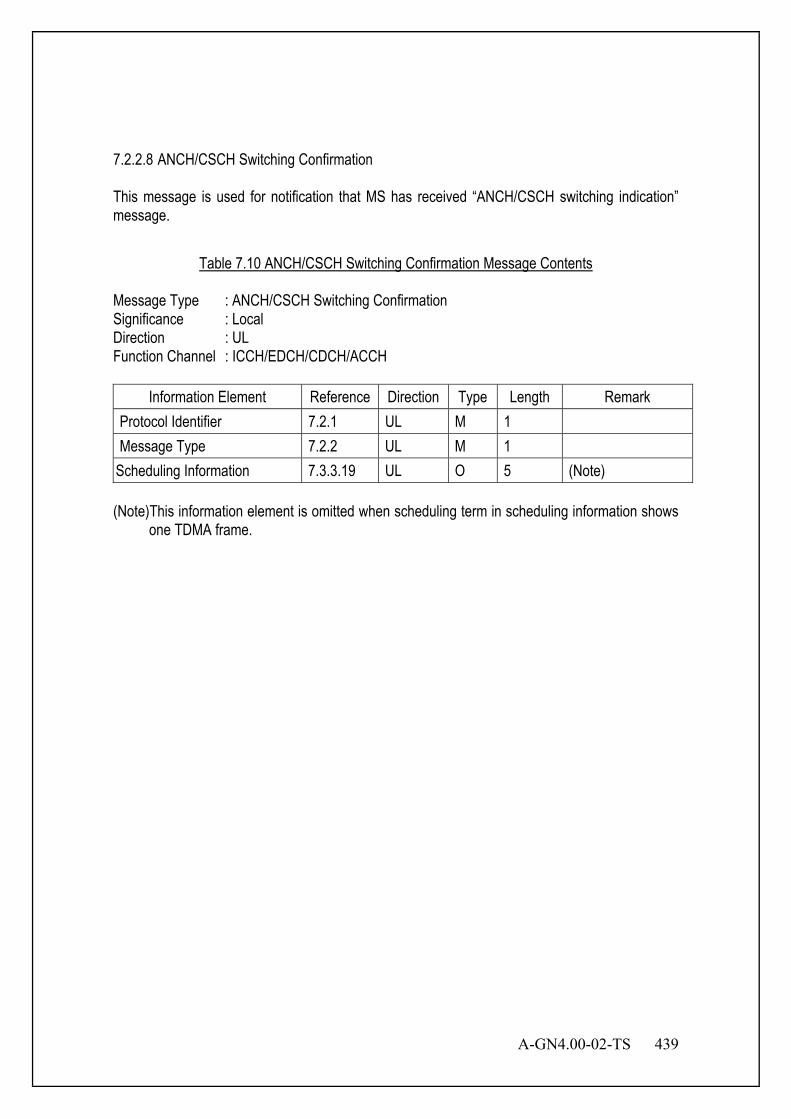
A-GN4.00-02-TS 439
7.2.2.8 ANCH/CSCH Switching Confirmation This message is used for notification that MS has received “ANCH/CSCH switching indication” message.
Table 7.10 ANCH/CSCH Switching Confirmation Message Contents
Message Type : ANCH/CSCH Switching Confirmation Significance : Local Direction : UL Function Channel : ICCH/EDCH/CDCH/ACCH
Information Element Reference Direction Type Length Remark Protocol Identifier 7.2.1 UL M 1 Message Type 7.2.2 UL M 1
Scheduling Information 7.3.3.19 UL O 5 (Note) (Note)This information element is omitted when scheduling term in scheduling information shows
one TDMA frame.
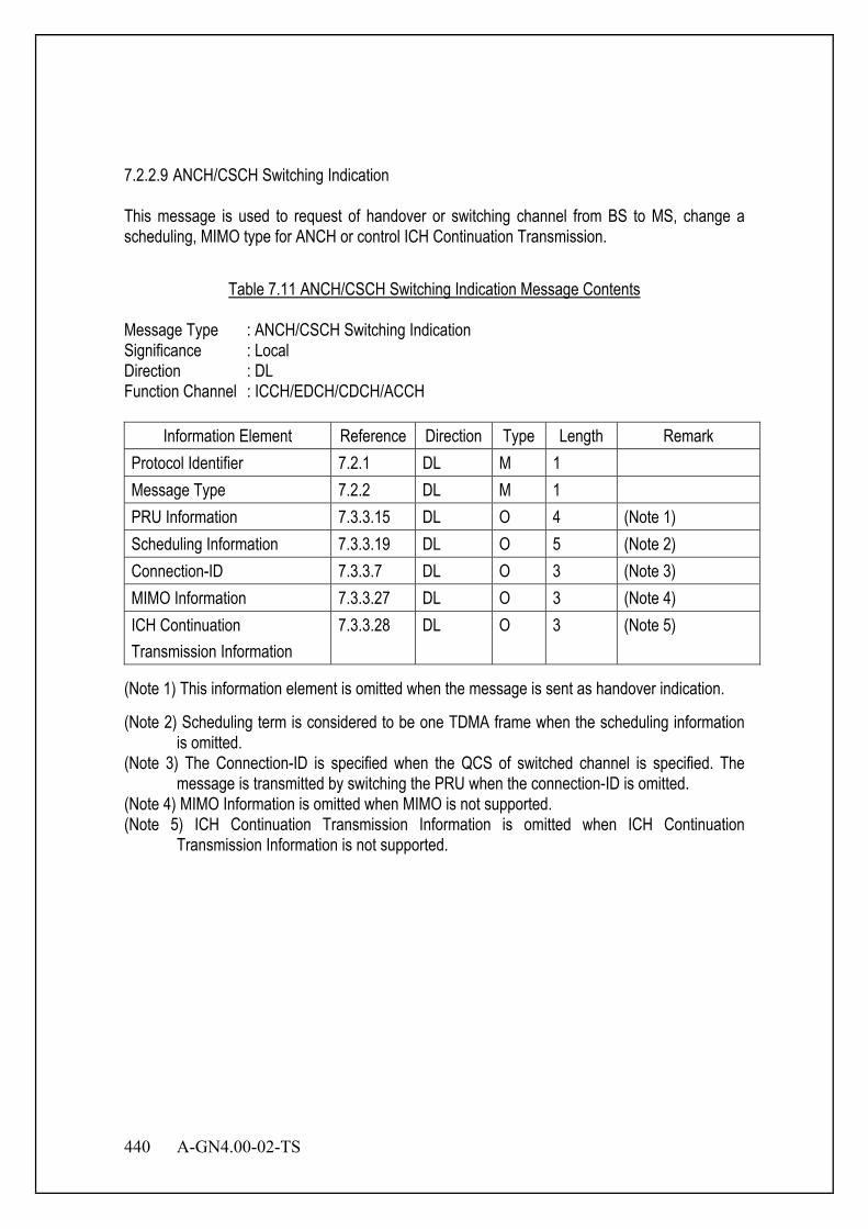
440 A-GN4.00-02-TS
7.2.2.9 ANCH/CSCH Switching Indication This message is used to request of handover or switching channel from BS to MS, change a scheduling, MIMO type for ANCH or control ICH Continuation Transmission.
Table 7.11 ANCH/CSCH Switching Indication Message Contents
Message Type : ANCH/CSCH Switching Indication Significance : Local Direction : DL Function Channel : ICCH/EDCH/CDCH/ACCH
Information Element Reference Direction Type Length Remark Protocol Identifier 7.2.1 DL M 1 Message Type 7.2.2 DL M 1 PRU Information 7.3.3.15 DL O 4 (Note 1) Scheduling Information 7.3.3.19 DL O 5 (Note 2) Connection-ID 7.3.3.7 DL O 3 (Note 3) MIMO Information 7.3.3.27 DL O 3 (Note 4) ICH Continuation Transmission Information
7.3.3.28 DL O 3 (Note 5)
(Note 1) This information element is omitted when the message is sent as handover indication.
(Note 2) Scheduling term is considered to be one TDMA frame when the scheduling information is omitted.
(Note 3) The Connection-ID is specified when the QCS of switched channel is specified. The message is transmitted by switching the PRU when the connection-ID is omitted.
(Note 4) MIMO Information is omitted when MIMO is not supported. (Note 5) ICH Continuation Transmission Information is omitted when ICH Continuation
Transmission Information is not supported.
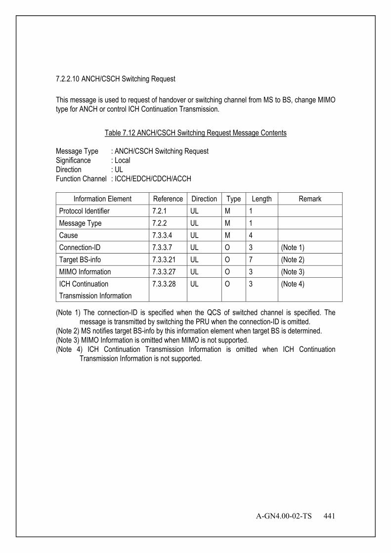
A-GN4.00-02-TS 441
7.2.2.10 ANCH/CSCH Switching Request This message is used to request of handover or switching channel from MS to BS, change MIMO type for ANCH or control ICH Continuation Transmission.
Table 7.12 ANCH/CSCH Switching Request Message Contents
Message Type : ANCH/CSCH Switching Request Significance : Local Direction : UL Function Channel : ICCH/EDCH/CDCH/ACCH
Information Element Reference Direction Type Length Remark Protocol Identifier 7.2.1 UL M 1 Message Type 7.2.2 UL M 1 Cause 7.3.3.4 UL M 4 Connection-ID 7.3.3.7 UL O 3 (Note 1) Target BS-info 7.3.3.21 UL O 7 (Note 2) MIMO Information 7.3.3.27 UL O 3 (Note 3) ICH Continuation Transmission Information
7.3.3.28 UL O 3 (Note 4)
(Note 1) The connection-ID is specified when the QCS of switched channel is specified. The message is transmitted by switching the PRU when the connection-ID is omitted.
(Note 2) MS notifies target BS-info by this information element when target BS is determined. (Note 3) MIMO Information is omitted when MIMO is not supported. (Note 4) ICH Continuation Transmission Information is omitted when ICH Continuation
Transmission Information is not supported.
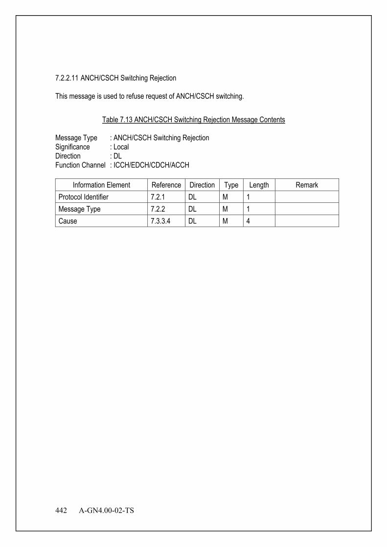
442 A-GN4.00-02-TS
7.2.2.11 ANCH/CSCH Switching Rejection This message is used to refuse request of ANCH/CSCH switching.
Table 7.13 ANCH/CSCH Switching Rejection Message Contents
Message Type : ANCH/CSCH Switching Rejection Significance : Local Direction : DL Function Channel : ICCH/EDCH/CDCH/ACCH
Information Element Reference Direction Type Length Remark Protocol Identifier 7.2.1 DL M 1 Message Type 7.2.2 DL M 1 Cause 7.3.3.4 DL M 4

A-GN4.00-02-TS 443
7.2.2.12 ANCH/CSCH Switching Re-request This message is used to re-request of handover or switching channel from MS to BS, retry to change MIMO type for ANCH or retry to control ICH Continuation Transmission, when MS has rejected ANCH/CSCH switching indication from BS.
Table 7.14 ANCH/CSCH Switching Re-request Message Contents
Message Type : ANCH/CSCH Switching Re-request Significance : Local Direction : UL Function Channel : ICCH/EDCH/CDCH/ACCH
Information Element Reference Direction Type Length Remark Protocol Identifier 7.2.1 UL M 1 Message Type 7.2.2 UL M 1 Cause 7.3.3.4 UL M 4 Connection-ID 7.3.3.7 UL O 3 (Note 1) Target BS-info 7.3.3.21 UL O 7 (Note 2) MIMO Information 7.3.3.27 UL O 3 (Note 3) ICH Continuation Transmission Information
7.3.3.28 UL O 3 (Note 4)
(Note 1) The connection-ID is specified when the QCS of switched channel is specified. The message is transmitted by switching the PRU when the connection-ID is omitted.
(Note 2) MS notifies target BS-info by this information element when target BS is determined. (Note 3) MIMO Information is omitted when MIMO is not supported. (Note 4) ICH Continuation Transmission Information is omitted when ICH Continuation
Transmission Information is not supported.
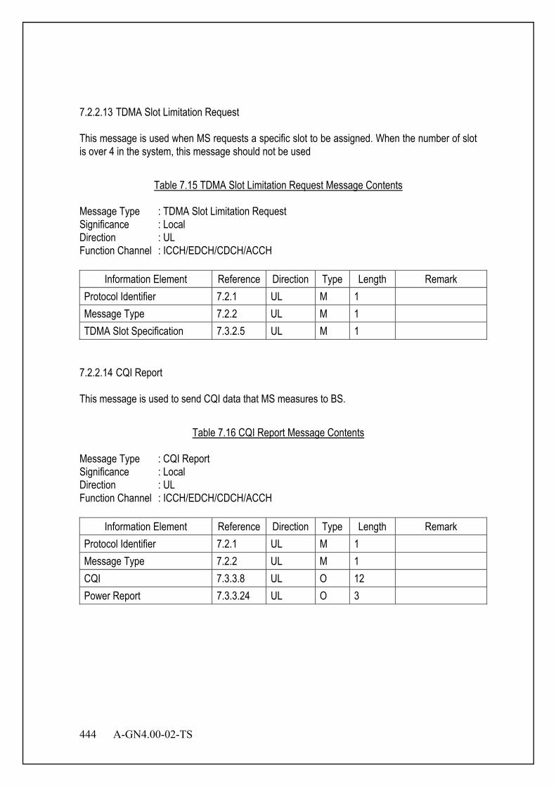
444 A-GN4.00-02-TS
7.2.2.13 TDMA Slot Limitation Request This message is used when MS requests a specific slot to be assigned. When the number of slot is over 4 in the system, this message should not be used
Table 7.15 TDMA Slot Limitation Request Message Contents
Message Type : TDMA Slot Limitation Request Significance : Local Direction : UL Function Channel : ICCH/EDCH/CDCH/ACCH
Information Element Reference Direction Type Length Remark Protocol Identifier 7.2.1 UL M 1 Message Type 7.2.2 UL M 1 TDMA Slot Specification 7.3.2.5 UL M 1
7.2.2.14 CQI Report This message is used to send CQI data that MS measures to BS.
Table 7.16 CQI Report Message Contents
Message Type : CQI Report Significance : Local Direction : UL Function Channel : ICCH/EDCH/CDCH/ACCH
Information Element Reference Direction Type Length Remark Protocol Identifier 7.2.1 UL M 1 Message Type 7.2.2 UL M 1 CQI 7.3.3.8 UL O 12 Power Report 7.3.3.24 UL O 3
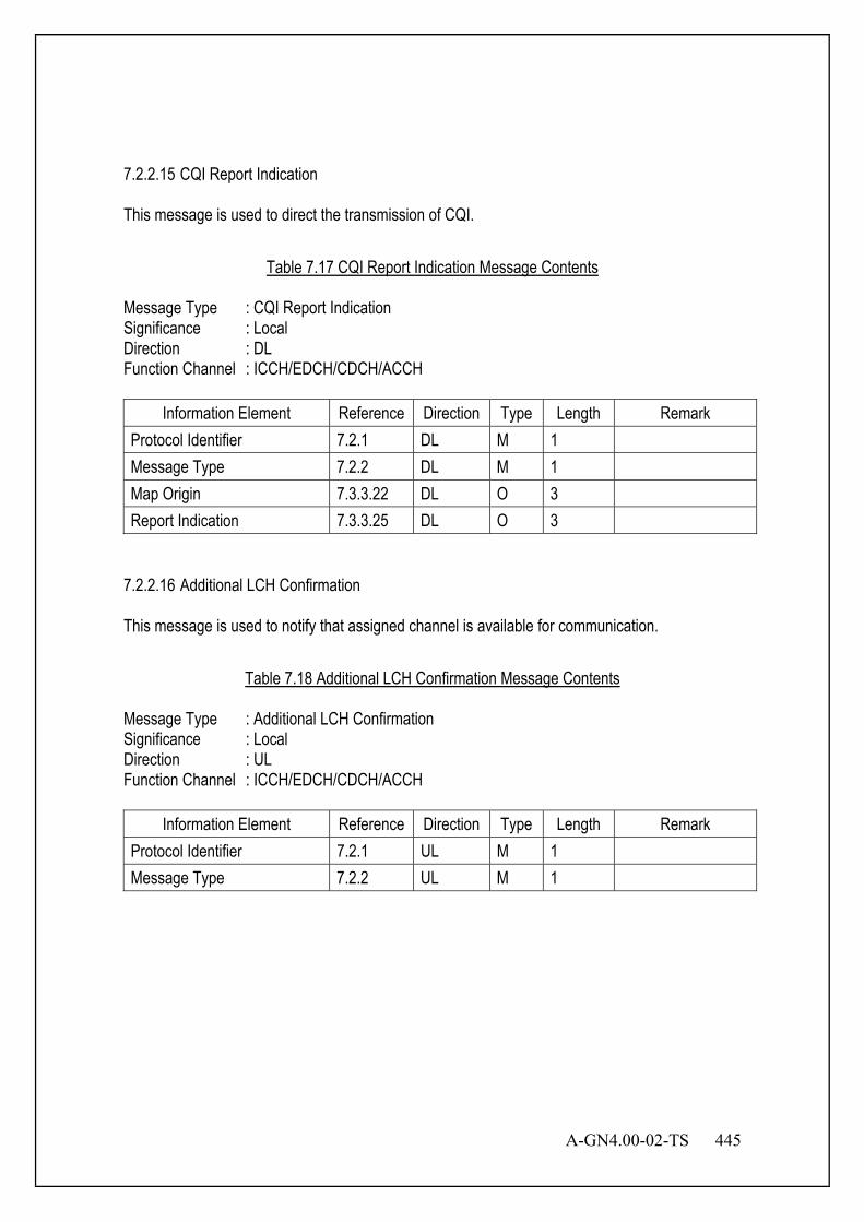
A-GN4.00-02-TS 445
7.2.2.15 CQI Report Indication This message is used to direct the transmission of CQI.
Table 7.17 CQI Report Indication Message Contents
Message Type : CQI Report Indication Significance : Local Direction : DL Function Channel : ICCH/EDCH/CDCH/ACCH
Information Element Reference Direction Type Length Remark Protocol Identifier 7.2.1 DL M 1 Message Type 7.2.2 DL M 1 Map Origin 7.3.3.22 DL O 3 Report Indication 7.3.3.25 DL O 3
7.2.2.16 Additional LCH Confirmation This message is used to notify that assigned channel is available for communication.
Table 7.18 Additional LCH Confirmation Message Contents
Message Type : Additional LCH Confirmation Significance : Local Direction : UL Function Channel : ICCH/EDCH/CDCH/ACCH
Information Element Reference Direction Type Length Remark Protocol Identifier 7.2.1 UL M 1 Message Type 7.2.2 UL M 1

446 A-GN4.00-02-TS
7.2.2.17 Additional LCH Indication This message is used for notification of channel type and PRU information at adding connection-ID.
Table 7.19 Additional LCH Indication Message Contents
Message Type : Additional LCH Indication Significance : Local Direction : DL Function Channel : ICCH/EDCH/CDCH/ACCH
Information Element Reference Direction Type Length Remark Protocol Identifier 7.2.1 DL M 1 Message Type 7.2.2 DL M 1 PRU Information 7.3.3.15 DL M 4 Channel type 7.3.2.1 DL M 1
7.2.2.18 Additional QCS Request This message is used to request additional QoS.
Table 7.20 Additional QCS Request Message Contents
Message Type : Additional QCS Request Significance : Local Direction : UL Function Channel : ICCH/EDCH/CDCH/ACCH
Information Element Reference Direction Type Length Remark Protocol Identifier 7.2.1 UL M 1 Message Type 7.2.2 UL M 1 QoS 7.3.3.17 UL O 3 QCS Information 7.3.3.16 UL O 4 Connection type 7.3.2.2 UL M 1
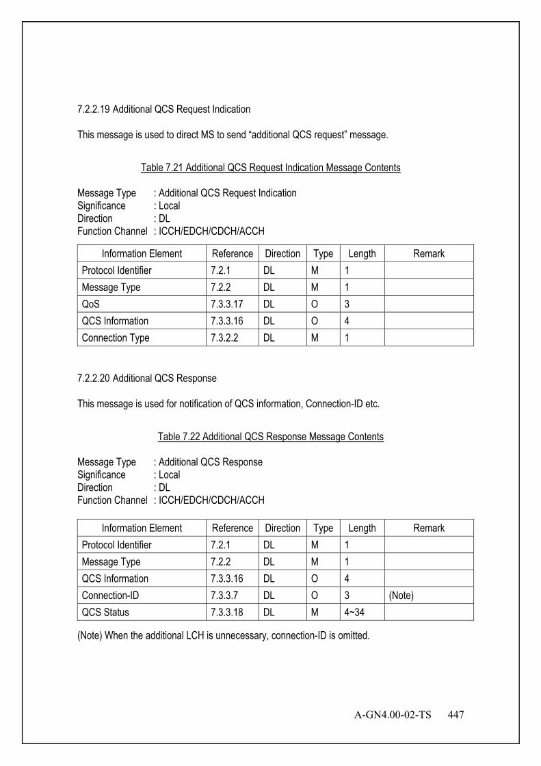
A-GN4.00-02-TS 447
7.2.2.19 Additional QCS Request Indication This message is used to direct MS to send “additional QCS request” message.
Table 7.21 Additional QCS Request Indication Message Contents
Message Type : Additional QCS Request Indication Significance : Local Direction : DL Function Channel : ICCH/EDCH/CDCH/ACCH
Information Element Reference Direction Type Length Remark Protocol Identifier 7.2.1 DL M 1 Message Type 7.2.2 DL M 1 QoS 7.3.3.17 DL O 3 QCS Information 7.3.3.16 DL O 4 Connection Type 7.3.2.2 DL M 1
7.2.2.20 Additional QCS Response This message is used for notification of QCS information, Connection-ID etc.
Table 7.22 Additional QCS Response Message Contents
Message Type : Additional QCS Response Significance : Local Direction : DL Function Channel : ICCH/EDCH/CDCH/ACCH
Information Element Reference Direction Type Length Remark Protocol Identifier 7.2.1 DL M 1 Message Type 7.2.2 DL M 1 QCS Information 7.3.3.16 DL O 4 Connection-ID 7.3.3.7 DL O 3 (Note) QCS Status 7.3.3.18 DL M 4~34
(Note) When the additional LCH is unnecessary, connection-ID is omitted.
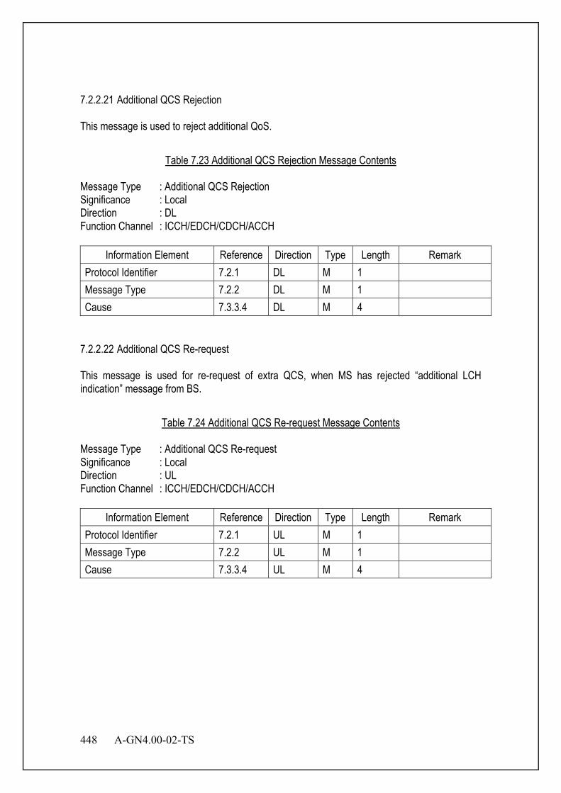
448 A-GN4.00-02-TS
7.2.2.21 Additional QCS Rejection This message is used to reject additional QoS.
Table 7.23 Additional QCS Rejection Message Contents
Message Type : Additional QCS Rejection Significance : Local Direction : DL Function Channel : ICCH/EDCH/CDCH/ACCH
Information Element Reference Direction Type Length Remark Protocol Identifier 7.2.1 DL M 1 Message Type 7.2.2 DL M 1 Cause 7.3.3.4 DL M 4
7.2.2.22 Additional QCS Re-request This message is used for re-request of extra QCS, when MS has rejected “additional LCH indication” message from BS.
Table 7.24 Additional QCS Re-request Message Contents
Message Type : Additional QCS Re-request Significance : Local Direction : UL Function Channel : ICCH/EDCH/CDCH/ACCH
Information Element Reference Direction Type Length Remark Protocol Identifier 7.2.1 UL M 1 Message Type 7.2.2 UL M 1 Cause 7.3.3.4 UL M 4
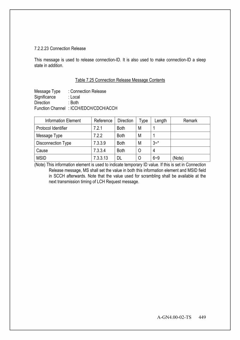
A-GN4.00-02-TS 449
7.2.2.23 Connection Release This message is used to release connection-ID. It is also used to make connection-ID a sleep state in addition.
Table 7.25 Connection Release Message Contents
Message Type : Connection Release Significance : Local Direction : Both Function Channel : ICCH/EDCH/CDCH/ACCH
Information Element Reference Direction Type Length Remark Protocol Identifier 7.2.1 Both M 1 Message Type 7.2.2 Both M 1 Disconnection Type 7.3.3.9 Both M 3~* Cause 7.3.3.4 Both O 4 MSID 7.3.3.13 DL O 6~9 (Note)
(Note) This information element is used to indicate temporary ID value. If this is set in Connection Release message, MS shall set the value in both this information element and MSID field in SCCH afterwards. Note that the value used for scrambling shall be available at the next transmission timing of LCH Request message.
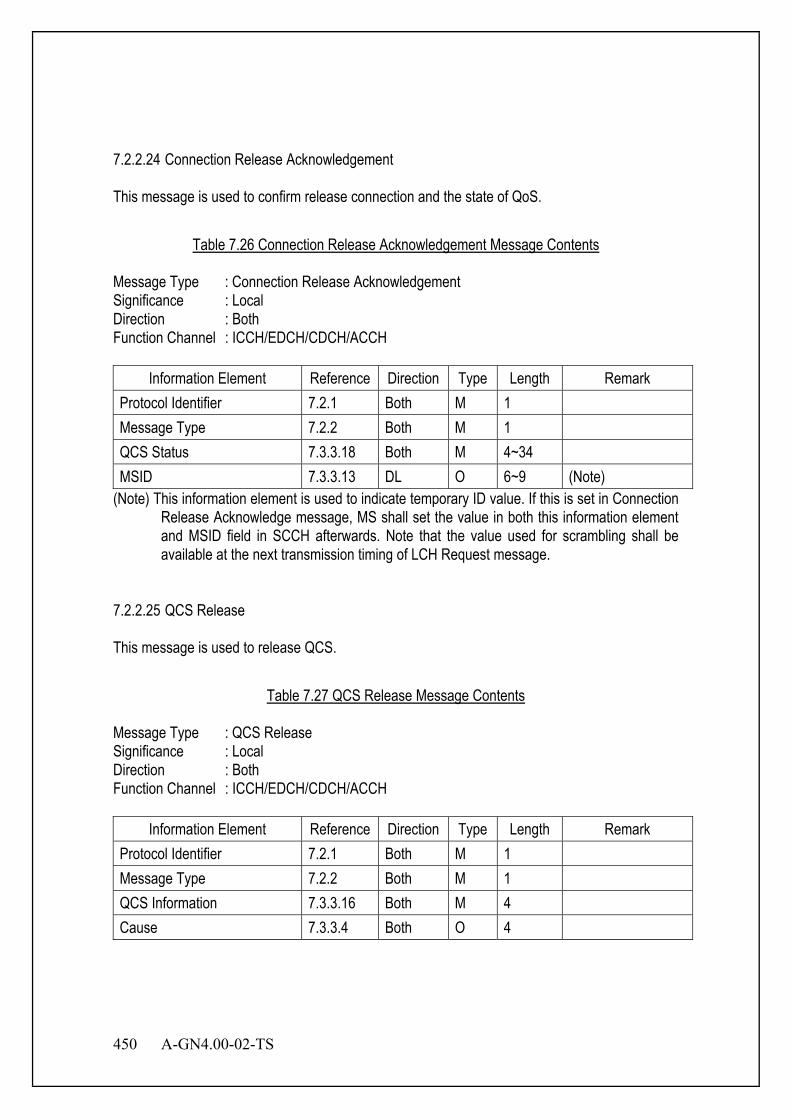
450 A-GN4.00-02-TS
7.2.2.24 Connection Release Acknowledgement This message is used to confirm release connection and the state of QoS.
Table 7.26 Connection Release Acknowledgement Message Contents
Message Type : Connection Release Acknowledgement Significance : Local Direction : Both Function Channel : ICCH/EDCH/CDCH/ACCH
Information Element Reference Direction Type Length Remark Protocol Identifier 7.2.1 Both M 1 Message Type 7.2.2 Both M 1 QCS Status 7.3.3.18 Both M 4~34 MSID 7.3.3.13 DL O 6~9 (Note)
(Note) This information element is used to indicate temporary ID value. If this is set in Connection Release Acknowledge message, MS shall set the value in both this information element and MSID field in SCCH afterwards. Note that the value used for scrambling shall be available at the next transmission timing of LCH Request message.
7.2.2.25 QCS Release This message is used to release QCS.
Table 7.27 QCS Release Message Contents
Message Type : QCS Release Significance : Local Direction : Both Function Channel : ICCH/EDCH/CDCH/ACCH
Information Element Reference Direction Type Length Remark Protocol Identifier 7.2.1 Both M 1 Message Type 7.2.2 Both M 1 QCS Information 7.3.3.16 Both M 4 Cause 7.3.3.4 Both O 4
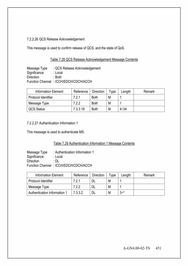
A-GN4.00-02-TS 451
7.2.2.26 QCS Release Acknowledgement This message is used to confirm release of QCS, and the state of QoS.
Table 7.28 QCS Release Acknowledgement Message Contents
Message Type : QCS Release Acknowledgement Significance : Local Direction : Both Function Channel : ICCH/EDCH/CDCH/ACCH
Information Element Reference Direction Type Length Remark Protocol Identifier 7.2.1 Both M 1 Message Type 7.2.2 Both M 1 QCS Status 7.3.3.18 Both M 4~34
7.2.2.27 Authentication Information 1 This message is used to authenticate MS.
Table 7.29 Authentication Information 1 Message Contents
Message Type : Authentication Information 1 Significance : Local Direction : DL Function Channel : ICCH/EDCH/CDCH/ACCH
Information Element Reference Direction Type Length Remark Protocol Identifier 7.2.1 DL M 1 Message Type 7.2.2 DL M 1 Authentication Information 1 7.3.3.2 DL M 3~*

452 A-GN4.00-02-TS
7.2.2.28 Authentication Information 2 This message is used to authenticate MS.
Table 7.30 Authentication Information 2 Message Contents
Message Type : Authentication Information 2 Significance : Local Direction : UL Function Channel : ICCH/EDCH/CDCH/ACCH
Information Element Reference Direction Type Length Remark Protocol Identifier 7.2.1 UL M 1 Message Type 7.2.2 UL M 1 Authentication Information 2 7.3.3.3 UL M 3~*
7.2.2.29 Encryption Key Indication This message is used to transmit encryption key to MS.
Table 7.31 Encryption Key Indication Message Contents
Message Type : Encryption Key Indication Significance : Local Direction : DL Function Channel : ICCH/EDCH/CDCH/ACCH
Information Element Reference Direction Type Length Remark Protocol Identifier 7.2.1 DL M 1 Message Type 7.2.2 DL M 1 Encryption Key Set 7.3.3.10 DL O 3~* Encryption Key Information 7.3.3.26 DL O 6

A-GN4.00-02-TS 453
7.2.2.30 QCS Status Enquiry Response This message is used to notify its own status of QCS or as a response to “QCS status enquiry request” message.
Table 7.32 QCS Status Enquiry Response Message Contents
Message Type : QCS Status Enquiry Response Significance : Local Direction : Both Function Channel : ICCH/EDCH/CDCH/ACCH
Information Element Reference Direction Type Length Remark Protocol Identifier 7.2.1 Both M 1 Message Type 7.2.2 Both M 1 QCS Status 7.3.3.18 Both M 4~34 Cause 7.3.3.4 Both O 4
7.2.2.31 QCS Status Enquiry Request This message is used to confirm QCS status. Response to the transmission of “QCS status enquiry response” message will be mandatory if this message is received.
Table 7.33 QCS Status Enquiry Request Message Contents
Message Type : QCS Status Enquiry Request Significance : Local Direction : Both Function Channel : ICCH/EDCH/CDCH/ACCH
Information Element Reference Direction Type Length Remark Protocol Identifier 7.2.1 Both M 1 Message Type 7.2.2 Both M 1 QCS Status 7.3.3.18 Both M 4~34
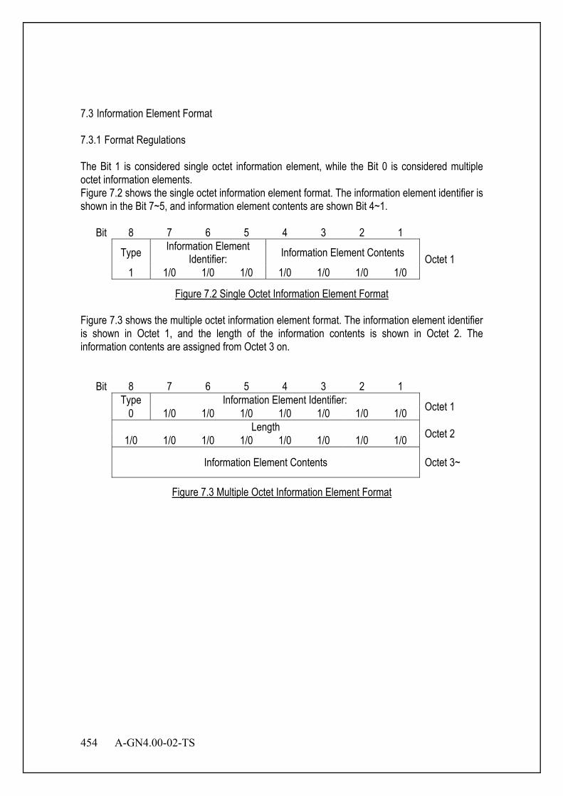
454 A-GN4.00-02-TS
7.3 Information Element Format 7.3.1 Format Regulations The Bit 1 is considered single octet information element, while the Bit 0 is considered multiple octet information elements. Figure 7.2 shows the single octet information element format. The information element identifier is shown in the Bit 7~5, and information element contents are shown Bit 4~1.
Bit 8 7 6 5 4 3 2 1
Type Information Element Identifier: Information Element Contents Octet 1
1 1/0 1/0 1/0 1/0 1/0 1/0 1/0
Figure 7.2 Single Octet Information Element Format
Figure 7.3 shows the multiple octet information element format. The information element identifier is shown in Octet 1, and the length of the information contents is shown in Octet 2. The information contents are assigned from Octet 3 on.
Bit 8 7 6 5 4 3 2 1 Type Information Element Identifier: Octet 1 0 1/0 1/0 1/0 1/0 1/0 1/0 1/0 Length Octet 2 1/0 1/0 1/0 1/0 1/0 1/0 1/0 1/0
Information Element Contents Octet 3~
Figure 7.3 Multiple Octet Information Element Format

A-GN4.00-02-TS 455
7.3.2 Single Octet Information Element Identifier Table 7.34 shows the single octet information element identifiers.
Table 7.34 Single Octet Information Element Identifier List
Information Name Information Identifier Bit 8 7 6 5 4 3 2 1
Channel Type 1 0 0 1 - - - - Connection Type 1 0 1 0 - - - - Extension Function Sequence 1 0 1 1 - - - - Result of Location Registration 1 1 0 0 - - - - TDMA Slot Specification 1 1 0 1 - - - -
7.3.2.1 Channel Type This information element is used to notify channel type.
Bit Octet 8 7 6 5 4 3 2 1
1 Type Channel Type Assign
Chan- nel
Type
Physical Channel Type
Re- served 1 0 0 1
Assign Channel Type (Octet 1)
Bit 4 0 ANCH 1 CSCH
Physical Channel Type (Octet 1)
Bit 3 2 - 0/1 ANCH absent/present 0/1 - CSCH absent/present
Figure 7.4 Channel Type
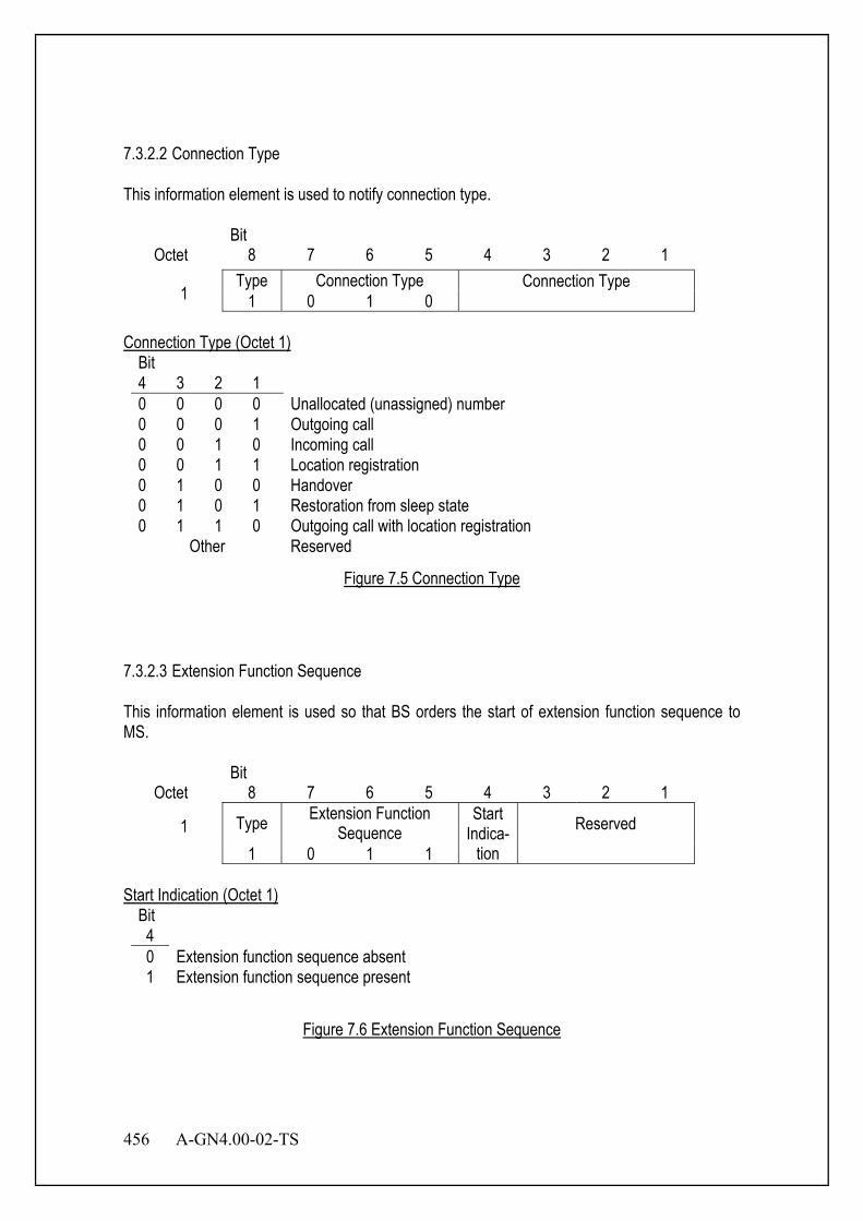
456 A-GN4.00-02-TS
7.3.2.2 Connection Type This information element is used to notify connection type.
Bit Octet 8 7 6 5 4 3 2 1
1 Type Connection Type Connection Type
1 0 1 0 Connection Type (Octet 1)
Bit 4 3 2 1 0 0 0 0 Unallocated (unassigned) number 0 0 0 1 Outgoing call 0 0 1 0 Incoming call 0 0 1 1 Location registration 0 1 0 0 Handover 0 1 0 1 Restoration from sleep state 0 1 1 0 Outgoing call with location registration
Other Reserved
Figure 7.5 Connection Type
7.3.2.3 Extension Function Sequence This information element is used so that BS orders the start of extension function sequence to MS.
Bit Octet 8 7 6 5 4 3 2 1
1 Type Extension Function Sequence
Start Indica-
tion Reserved
1 0 1 1 Start Indication (Octet 1)
Bit 4 0 Extension function sequence absent 1 Extension function sequence present
Figure 7.6 Extension Function Sequence
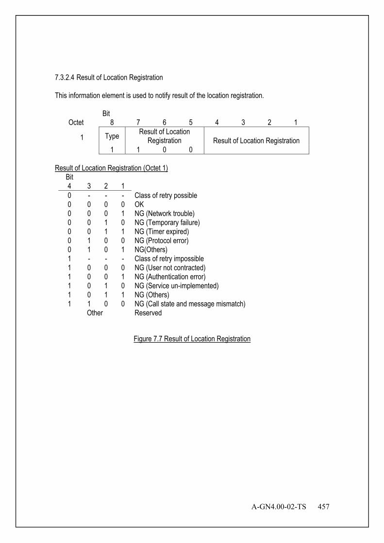
A-GN4.00-02-TS 457
7.3.2.4 Result of Location Registration This information element is used to notify result of the location registration.
Bit Octet 8 7 6 5 4 3 2 1
1 Type Result of Location Registration Result of Location Registration
1 1 0 0 Result of Location Registration (Octet 1)
Bit 4 3 2 1 0 - - - Class of retry possible 0 0 0 0 OK 0 0 0 1 NG (Network trouble) 0 0 1 0 NG (Temporary failure) 0 0 1 1 NG (Timer expired) 0 1 0 0 NG (Protocol error) 0 1 0 1 NG(Others) 1 - - - Class of retry impossible 1 0 0 0 NG (User not contracted) 1 0 0 1 NG (Authentication error) 1 0 1 0 NG (Service un-implemented) 1 0 1 1 NG (Others) 1 1 0 0 NG (Call state and message mismatch)
Other Reserved
Figure 7.7 Result of Location Registration
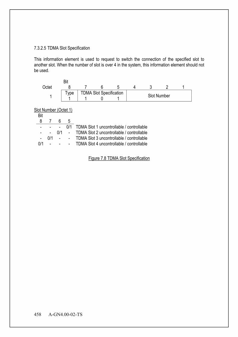
458 A-GN4.00-02-TS
7.3.2.5 TDMA Slot Specification This information element is used to request to switch the connection of the specified slot to another slot. When the number of slot is over 4 in the system, this information element should not be used.
Bit Octet 8 7 6 5 4 3 2 1
1 Type TDMA Slot Specification Slot Number 1 1 0 1
Slot Number (Octet 1)
Bit 8 7 6 5 - - - 0/1 TDMA Slot 1 uncontrollable / controllable - - 0/1 - TDMA Slot 2 uncontrollable / controllable - 0/1 - - TDMA Slot 3 uncontrollable / controllable
0/1 - - - TDMA Slot 4 uncontrollable / controllable
Figure 7.8 TDMA Slot Specification
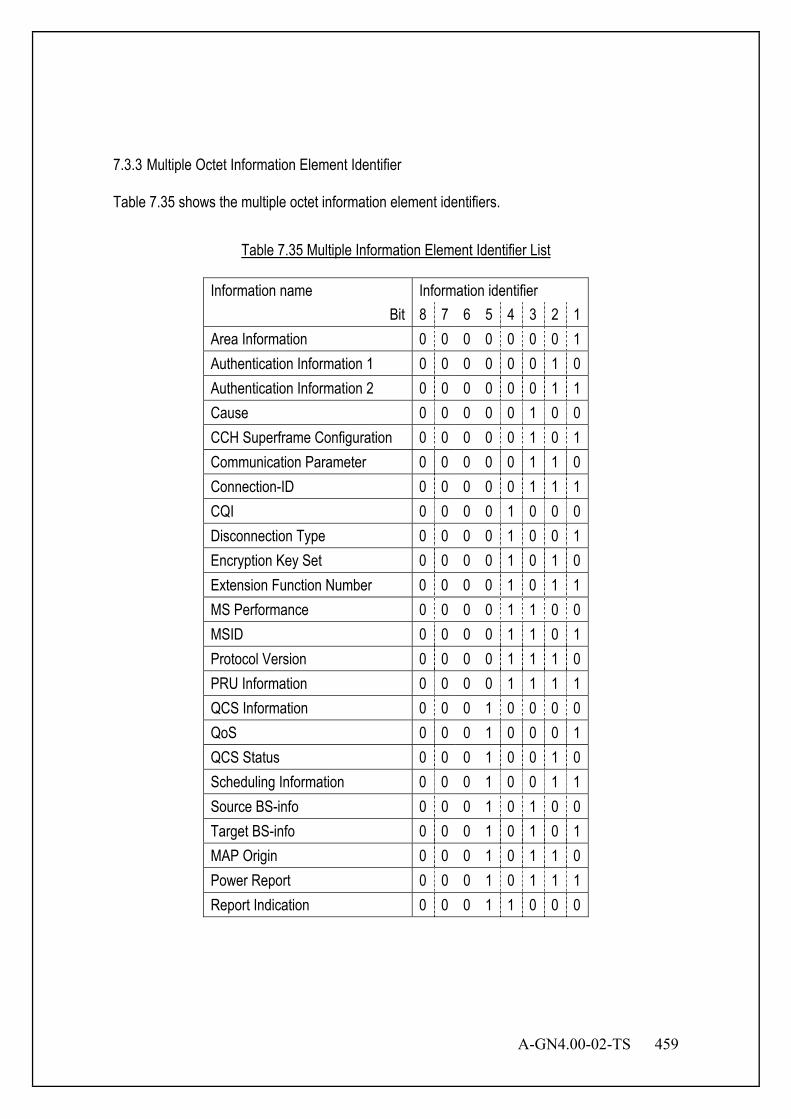
A-GN4.00-02-TS 459
7.3.3 Multiple Octet Information Element Identifier Table 7.35 shows the multiple octet information element identifiers.
Table 7.35 Multiple Information Element Identifier List
Information name Information identifier Bit 8 7 6 5 4 3 2 1
Area Information 0 0 0 0 0 0 0 1 Authentication Information 1 0 0 0 0 0 0 1 0 Authentication Information 2 0 0 0 0 0 0 1 1 Cause 0 0 0 0 0 1 0 0 CCH Superframe Configuration 0 0 0 0 0 1 0 1 Communication Parameter 0 0 0 0 0 1 1 0 Connection-ID 0 0 0 0 0 1 1 1 CQI 0 0 0 0 1 0 0 0 Disconnection Type 0 0 0 0 1 0 0 1 Encryption Key Set 0 0 0 0 1 0 1 0 Extension Function Number 0 0 0 0 1 0 1 1 MS Performance 0 0 0 0 1 1 0 0 MSID 0 0 0 0 1 1 0 1 Protocol Version 0 0 0 0 1 1 1 0 PRU Information 0 0 0 0 1 1 1 1 QCS Information 0 0 0 1 0 0 0 0 QoS 0 0 0 1 0 0 0 1 QCS Status 0 0 0 1 0 0 1 0 Scheduling Information 0 0 0 1 0 0 1 1 Source BS-info 0 0 0 1 0 1 0 0 Target BS-info 0 0 0 1 0 1 0 1 MAP Origin 0 0 0 1 0 1 1 0 Power Report 0 0 0 1 0 1 1 1 Report Indication 0 0 0 1 1 0 0 0
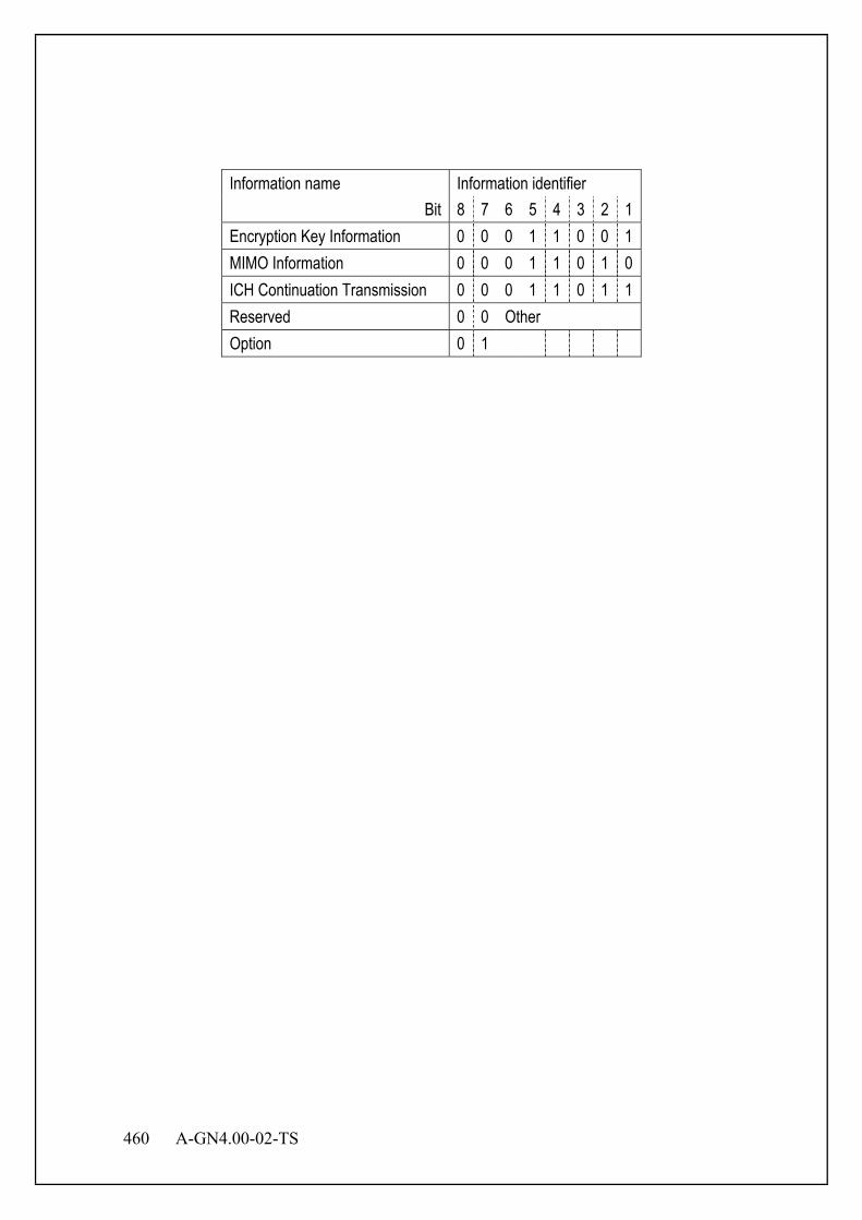
460 A-GN4.00-02-TS
Information name Information identifier
Bit 8 7 6 5 4 3 2 1 Encryption Key Information 0 0 0 1 1 0 0 1 MIMO Information 0 0 0 1 1 0 1 0 ICH Continuation Transmission 0 0 0 1 1 0 1 1 Reserved 0 0 Other Option 0 1
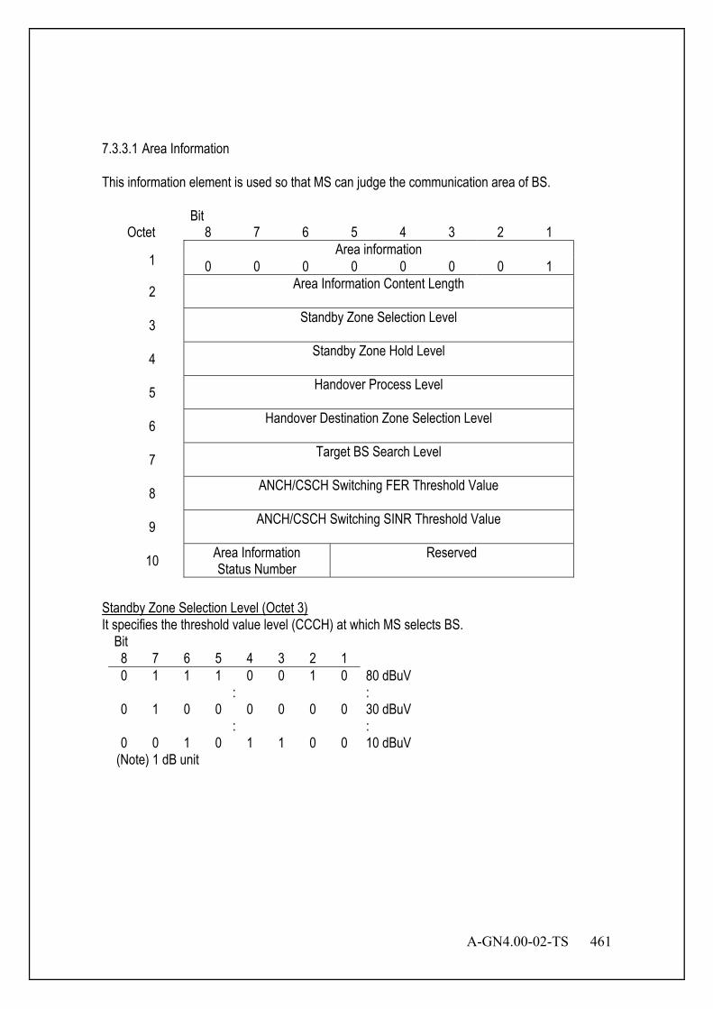
A-GN4.00-02-TS 461
7.3.3.1 Area Information This information element is used so that MS can judge the communication area of BS.
Bit Octet 8 7 6 5 4 3 2 1
1 Area information
0 0 0 0 0 0 0 1
2 Area Information Content Length
3 Standby Zone Selection Level
4 Standby Zone Hold Level
5 Handover Process Level
6 Handover Destination Zone Selection Level
7 Target BS Search Level
8 ANCH/CSCH Switching FER Threshold Value
9 ANCH/CSCH Switching SINR Threshold Value
10 Area Information Status Number
Reserved
Standby Zone Selection Level (Octet 3) It specifies the threshold value level (CCCH) at which MS selects BS.
(Note) 1 dB unit
Bit 8 7 6 5 4 3 2 1 0 1 1 1 0 0 1 0 80 dBuV
: : 0 1 0 0 0 0 0 0 30 dBuV
: : 0 0 1 0 1 1 0 0 10 dBuV
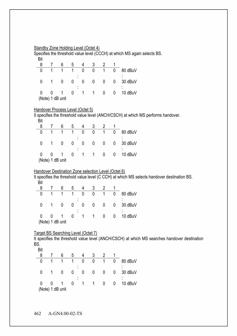
462 A-GN4.00-02-TS
Standby Zone Holding Level (Octet 4) Specifies the threshold value level (CCCH) at which MS again selects BS.
Bit 8 7 6 5 4 3 2 1 0 1 1 1 0 0 1 0 80 dBuV
: : 0 1 0 0 0 0 0 0 30 dBuV
: : 0 0 1 0 1 1 0 0 10 dBuV
(Note) 1 dB unit Handover Process Level (Octet 5) It specifies the threshold value level (ANCH/CSCH) at which MS performs handover.
Bit 8 7 6 5 4 3 2 1 0 1 1 1 0 0 1 0 80 dBuV
: : 0 1 0 0 0 0 0 0 30 dBuV
: : 0 0 1 0 1 1 0 0 10 dBuV
(Note) 1 dB unit Handover Destination Zone selection Level (Octet 6) It specifies the threshold value level (C CCH) at which MS selects handover destination BS.
Bit 8 7 6 5 4 3 2 1 0 1 1 1 0 0 1 0 80 dBuV
: : 0 1 0 0 0 0 0 0 30 dBuV
: : 0 0 1 0 1 1 0 0 10 dBuV
(Note) 1 dB unit Target BS Searching Level (Octet 7) It specifies the threshold value level (ANCH/CSCH) at which MS searches handover destination BS.
Bit 8 7 6 5 4 3 2 1 0 1 1 1 0 0 1 0 80 dBuV
: : 0 1 0 0 0 0 0 0 30 dBuV
: : 0 0 1 0 1 1 0 0 10 dBuV
(Note) 1 dB unit

A-GN4.00-02-TS 463
ANCH/CSCH Switching FER Threshold Value (Octet 8) It specifies the number of errors of the 240 slots. And FER threshold value (ANCH/CSCH) shows the number of errors at which the channel switching function of MS is activated.
Bit 8 7 6 5 4 3 2 1 0 0 0 0 0 0 0 0 Number of slot errors n = 0 0 0 0 0 0 0 0 1 Number of slot errors n = 1
: : 1 1 1 1 0 0 0 0 Number of slot errors n = 240
Other Reserved ANCH/CSCH Switching SINR Threshold Value (Octet 9) It specifies the SINR threshold value (ANCH/CSCH) at which MS performs channel switching because of reception quality degradation.
Bit 8 7 6 5 4 3 2 1 1 1 1 1 0 1 1 0 SINR = -10 dB
: : 1 1 1 1 1 1 1 1 SINR = -1 dB 0 0 0 0 0 0 0 0 SINR = 0 dB 0 0 0 0 0 0 0 1 SINR = 1 dB 0 0 1 0 1 0 0 0 SINR = 40 dB
Other Reserved Area Information Status Number (Octet 10) It shows the status number of area information reported by this information element.
Bit 8 7 6 0 0 0 No Area Information 0 0 1 Status number 1
: : 1 1 1 Status number 7
Figure 7.9 Area Information
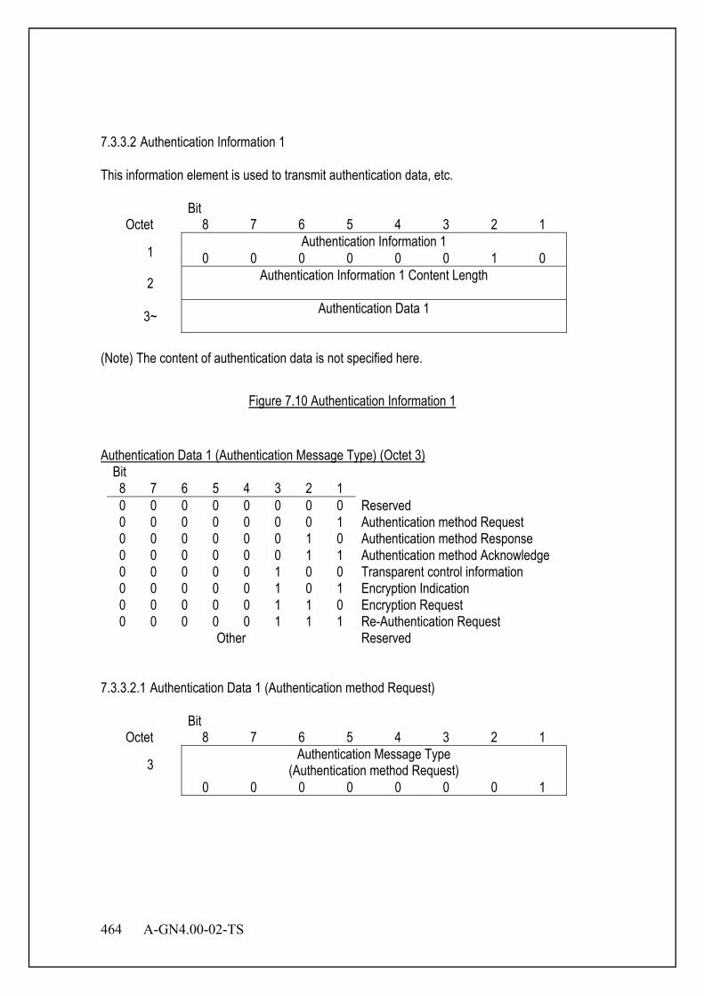
464 A-GN4.00-02-TS
7.3.3.2 Authentication Information 1 This information element is used to transmit authentication data, etc.
Bit Octet 8 7 6 5 4 3 2 1
1 Authentication Information 1
0 0 0 0 0 0 1 0
2 Authentication Information 1 Content Length
3~ Authentication Data 1
(Note) The content of authentication data is not specified here.
Figure 7.10 Authentication Information 1
Authentication Data 1 (Authentication Message Type) (Octet 3)
Bit 8 7 6 5 4 3 2 1 0 0 0 0 0 0 0 0 Reserved 0 0 0 0 0 0 0 1 Authentication method Request 0 0 0 0 0 0 1 0 Authentication method Response 0 0 0 0 0 0 1 1 Authentication method Acknowledge 0 0 0 0 0 1 0 0 Transparent control information 0 0 0 0 0 1 0 1 Encryption Indication 0 0 0 0 0 1 1 0 Encryption Request 0 0 0 0 0 1 1 1 Re-Authentication Request
Other Reserved 7.3.3.2.1 Authentication Data 1 (Authentication method Request)
Bit Octet 8 7 6 5 4 3 2 1
3 Authentication Message Type
(Authentication method Request) 0 0 0 0 0 0 0 1
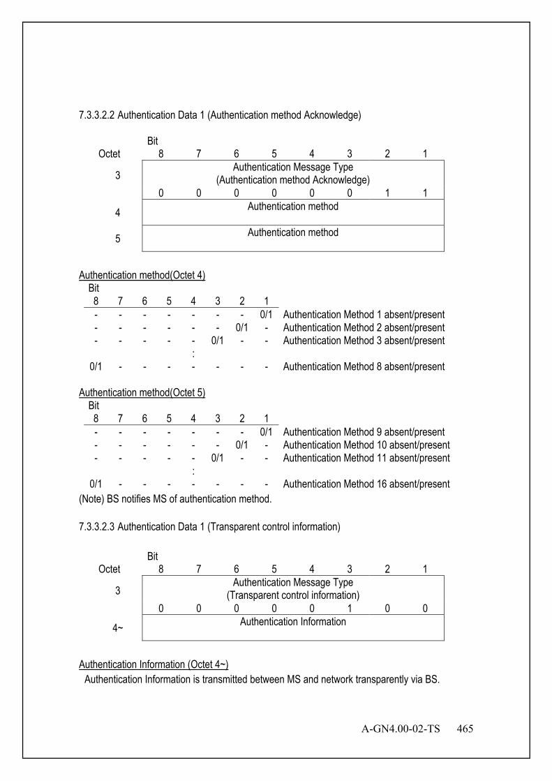
A-GN4.00-02-TS 465
7.3.3.2.2 Authentication Data 1 (Authentication method Acknowledge)
Bit Octet 8 7 6 5 4 3 2 1
3 Authentication Message Type
(Authentication method Acknowledge) 0 0 0 0 0 0 1 1
4 Authentication method
5 Authentication method
Authentication method(Octet 4)
Bit 8 7 6 5 4 3 2 1 - - - - - - - 0/1 Authentication Method 1 absent/present - - - - - - 0/1 - Authentication Method 2 absent/present - - - - - 0/1 - - Authentication Method 3 absent/present :
0/1 - - - - - - - Authentication Method 8 absent/present Authentication method(Octet 5)
Bit 8 7 6 5 4 3 2 1 - - - - - - - 0/1 Authentication Method 9 absent/present - - - - - - 0/1 - Authentication Method 10 absent/present - - - - - 0/1 - - Authentication Method 11 absent/present :
0/1 - - - - - - - Authentication Method 16 absent/present (Note) BS notifies MS of authentication method. 7.3.3.2.3 Authentication Data 1 (Transparent control information)
Bit Octet 8 7 6 5 4 3 2 1
3 Authentication Message Type
(Transparent control information) 0 0 0 0 0 1 0 0
4~ Authentication Information
Authentication Information (Octet 4~) Authentication Information is transmitted between MS and network transparently via BS.

466 A-GN4.00-02-TS
7.3.3.2.4 Authentication Data 1 (Encryption Indication)
Bit Octet 8 7 6 5 4 3 2 1
3 Authentication Message Type
(Encryption Indication) 0 0 0 0 0 1 0 1
4 Encryption Method
5 Encryption Method
6~21 Random Number
Encryption Method (Octet 4)
Bit 8 7 6 5 4 3 2 1
0/1 - - - - - - - Encryption Method 1 absent/present - 0/1 - - - - - - Encryption Method 2 absent/present - - 0/1 - - - - - Encryption Method 3 absent/present : - - - - - - - 0/1 Encryption Method 8 absent/present
Encryption Method (Octet 5)
Bit 8 7 6 5 4 3 2 1
0/1 - - - - - - - Encryption Method 9 absent/present - 0/1 - - - - - - Encryption Method 10 absent/present - - 0/1 - - - - - Encryption Method 11 absent/present : - - - - - - - 0/1 Encryption Method 16 absent/present
Random Number (Octet 6~21) Challenge value for challenge and response authentication check. This is a random value.

A-GN4.00-02-TS 467
7.3.3.3 Authentication Information 2 This information element is used to transmit authentication data etc.
Bit Octet 8 7 6 5 4 3 2 1
1 Authentication Information 2
0 0 0 0 0 0 1 1
2 Authentication Information 2 Content Length
3~ Authentication Data 2
(Note) The content of authentication data is not specified here.
Figure 7.11 Authentication Information 2
Authentication Data 2 (Authentication Message Type) (Octet 3)
Bit 8 7 6 5 4 3 2 1 0 0 0 0 0 0 0 0 Reserved 0 0 0 0 0 0 0 1 Authentication method Request 0 0 0 0 0 0 1 0 Authentication method Response 0 0 0 0 0 0 1 1 Authentication method Acknowledge 0 0 0 0 0 1 0 0 Transparent control information 0 0 0 0 0 1 0 1 Encryption Indication 0 0 0 0 0 1 1 0 Encryption Request 0 0 0 0 0 1 1 1 Re-Authentication Request
Other Reserved

468 A-GN4.00-02-TS
7.3.3.3.1 Authentication Data 2 (Authentication method Response)
Bit Octet 8 7 6 5 4 3 2 1
3 Authentication Message Type
(Authentication method Response) 0 0 0 0 0 0 1 0
4 Authentication method
5 Authentication method
Authentication method(Octet 4)
Bit 8 7 6 5 4 3 2 1 - - - - - - - 0/1 Authentication Method 1 absent/present - - - - - - 0/1 - Authentication Method 2 absent/present - - - - - 0/1 - - Authentication Method 3 absent/present :
0/1 - - - - - - - Authentication Method 8 absent/present Authentication method(Octet 5)
Bit 8 7 6 5 4 3 2 1 - - - - - - - 0/1 Authentication Method 9 absent/present - - - - - - 0/1 - Authentication Method 10 absent/present - - - - - 0/1 - - Authentication Method 11 absent/present :
0/1 - - - - - - - Authentication Method 16 absent/present
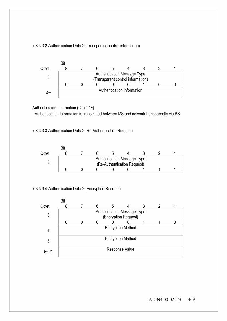
A-GN4.00-02-TS 469
7.3.3.3.2 Authentication Data 2 (Transparent control information)
Bit Octet 8 7 6 5 4 3 2 1
3 Authentication Message Type
(Transparent control information) 0 0 0 0 0 1 0 0
4~ Authentication Information
Authentication Information (Octet 4~) Authentication Information is transmitted between MS and network transparently via BS. 7.3.3.3.3 Authentication Data 2 (Re-Authentication Request)
Bit Octet 8 7 6 5 4 3 2 1
3 Authentication Message Type (Re-Authentication Request)
0 0 0 0 0 1 1 1 7.3.3.3.4 Authentication Data 2 (Encryption Request)
Bit Octet 8 7 6 5 4 3 2 1
3 Authentication Message Type
(Encryption Request) 0 0 0 0 0 1 1 0
4 Encryption Method
5 Encryption Method
6~21 Response Value

470 A-GN4.00-02-TS
Encryption Method (Octet 4)
Bit 8 7 6 5 4 3 2 1
0/1 - - - - - - - Encryption Method 1 absent/present - 0/1 - - - - - - Encryption Method 2 absent/present - - 0/1 - - - - - Encryption Method 3 absent/present : Encryption Method 4 absent/present - - - - - - - 0/1 Encryption Method 8 absent/present
Encryption Method (Octet 5)
Bit 8 7 6 5 4 3 2 1
0/1 - - - - - - - Encryption Method 9 absent/present - 0/1 - - - - - - Encryption Method 10 absent/present - - 0/1 - - - - - Encryption Method 11 absent/present : Encryption Method 12 absent/present - - - - - - - 0/1 Encryption Method 16 absent/present
Response Value (Octet 6~21) Response value for challenge and response check. 7.3.3.4 Cause The information element is used to describe the reason and location of message generation.
Bit Octet 8 7 6 5 4 3 2 1
1 Cause
0 0 0 0 0 1 0 0
2 Cause Content Length
3 Coding Standard
Location
Reserved
4 Cause Value
Re- served
Coding Standard (Octet 3)
Bit 8 7 0 0 XGP 1 1 Specific to the local network standard Other Reserved
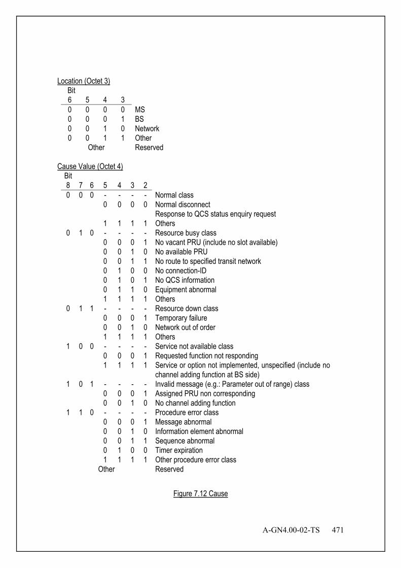
A-GN4.00-02-TS 471
Location (Octet 3)
Bit 6 5 4 3 0 0 0 0 MS 0 0 0 1 BS 0 0 1 0 Network 0 0 1 1 Other
Other Reserved Cause Value (Octet 4)
Bit 8 7 6 5 4 3 2 0 0 0 - - - - Normal class 0 0 0 0 Normal disconnect Response to QCS status enquiry request 1 1 1 1 Others
0 1 0 - - - - Resource busy class 0 0 0 1 No vacant PRU (include no slot available) 0 0 1 0 No available PRU 0 0 1 1 No route to specified transit network 0 1 0 0 No connection-ID 0 1 0 1 No QCS information 0 1 1 0 Equipment abnormal 1 1 1 1 Others
0 1 1 - - - - Resource down class 0 0 0 1 Temporary failure 0 0 1 0 Network out of order 1 1 1 1 Others
1 0 0 - - - - Service not available class 0 0 0 1 Requested function not responding 1 1 1 1 Service or option not implemented, unspecified (include no
channel adding function at BS side) 1 0 1 - - - - Invalid message (e.g.: Parameter out of range) class 0 0 0 1 Assigned PRU non corresponding 0 0 1 0 No channel adding function
1 1 0 - - - - Procedure error class 0 0 0 1 Message abnormal 0 0 1 0 Information element abnormal 0 0 1 1 Sequence abnormal 0 1 0 0 Timer expiration 1 1 1 1 Other procedure error class
Other Reserved
Figure 7.12 Cause

472 A-GN4.00-02-TS
7.3.3.5 CCH Superframe Configuration This information element is used to notify superframe configuration of CCH.
Bit Octet 8 7 6 5 4 3 2 1
1 CCH Superframe Configuration
0 0 0 0 0 1 0 1
2 CCH Superframe Configuration Content Length
3 Reserved LCCH Interval Value n 4 Paging Grouping Factor nGROUP Paging Area Number Length np
5 Reserved Number of Same Paging Groups nSG
Battery Saving Cycle Maximum Value nBS
6 Control Carrier Structure
PCH Number nPCH Frame Basic Unit Length nSUB
7 Reserved
8 Re- served
Broadcasting Status Indication
Global Definition Information Pattern
9 Protocol Version
10 Reserved BSID Area Bit Length nBL
11 MCC (Mobile Country Code) 12 MNC (Mobile Network Code) 13
LCCH Interval Value n (Octet 3) It shows the DL LCCH slot intermittent cycle. Bit 6 5 4 3 2 1 0 0 0 0 0 0 Reserved 0 0 0 0 0 1 n = 1 0 0 0 0 1 0 n = 2 0 0 0 0 1 1 n = 3
: : 0 1 0 1 0 0 n = 20
: : 1 1 1 1 1 1 n = 63
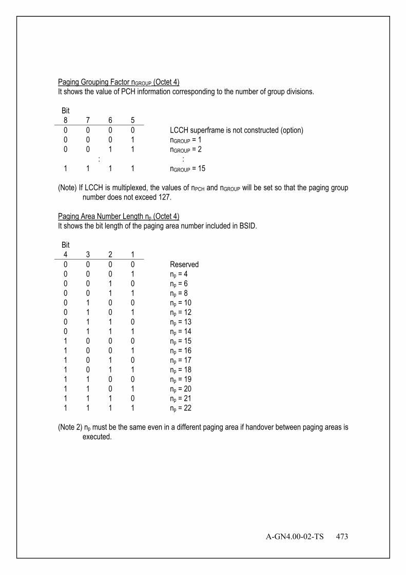
A-GN4.00-02-TS 473
Paging Grouping Factor nGROUP (Octet 4) It shows the value of PCH information corresponding to the number of group divisions. Bit 8 7 6 5 0 0 0 0 LCCH superframe is not constructed (option) 0 0 0 1 nGROUP = 1 0 0 1 1 nGROUP = 2
: : 1 1 1 1 nGROUP = 15
(Note) If LCCH is multiplexed, the values of nPCH and nGROUP will be set so that the paging group
number does not exceed 127. Paging Area Number Length np (Octet 4) It shows the bit length of the paging area number included in BSID. Bit 4 3 2 1 0 0 0 0 Reserved 0 0 0 1 np = 4 0 0 1 0 np = 6 0 0 1 1 np = 8 0 1 0 0 np = 10 0 1 0 1 np = 12 0 1 1 0 np = 13 0 1 1 1 np = 14 1 0 0 0 np = 15 1 0 0 1 np = 16 1 0 1 0 np = 17 1 0 1 1 np = 18 1 1 0 0 np = 19 1 1 0 1 np = 20 1 1 1 0 np = 21 1 1 1 1 np = 22
(Note 2) np must be the same even in a different paging area if handover between paging areas is
executed.
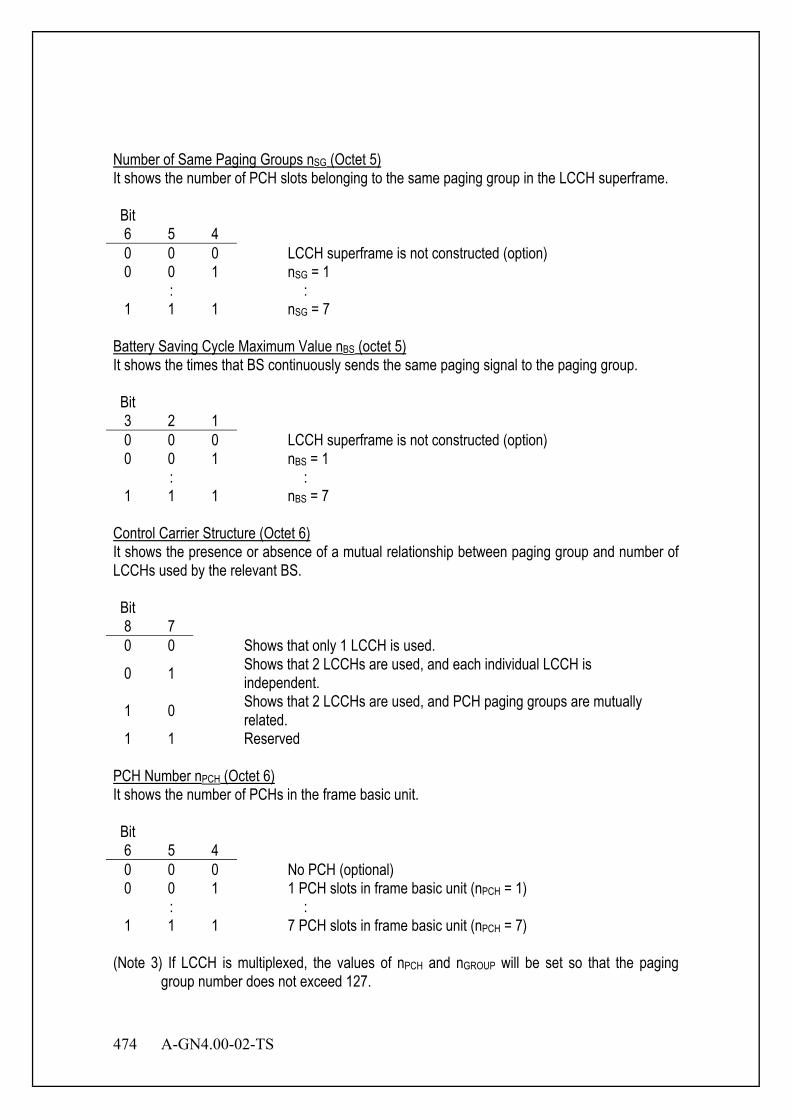
474 A-GN4.00-02-TS
Number of Same Paging Groups nSG (Octet 5) It shows the number of PCH slots belonging to the same paging group in the LCCH superframe. Bit 6 5 4 0 0 0 LCCH superframe is not constructed (option) 0 0 1 nSG = 1
: : 1 1 1 nSG = 7
Battery Saving Cycle Maximum Value nBS (octet 5) It shows the times that BS continuously sends the same paging signal to the paging group. Bit 3 2 1 0 0 0 LCCH superframe is not constructed (option) 0 0 1 nBS = 1
: : 1 1 1 nBS = 7
Control Carrier Structure (Octet 6) It shows the presence or absence of a mutual relationship between paging group and number of LCCHs used by the relevant BS. Bit 8 7 0 0 Shows that only 1 LCCH is used.
0 1 Shows that 2 LCCHs are used, and each individual LCCH is independent.
1 0 Shows that 2 LCCHs are used, and PCH paging groups are mutually related.
1 1 Reserved PCH Number nPCH (Octet 6) It shows the number of PCHs in the frame basic unit. Bit 6 5 4 0 0 0 No PCH (optional) 0 0 1 1 PCH slots in frame basic unit (nPCH = 1)
: : 1 1 1 7 PCH slots in frame basic unit (nPCH = 7)
(Note 3) If LCCH is multiplexed, the values of nPCH and nGROUP will be set so that the paging
group number does not exceed 127.
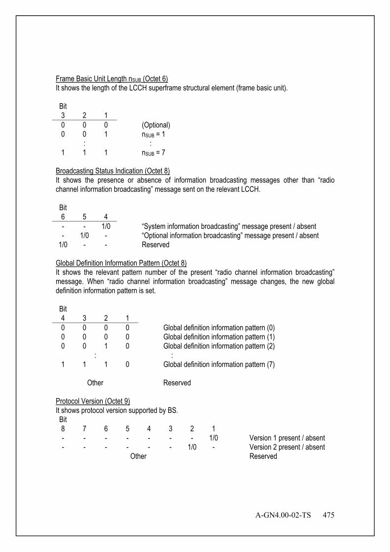
A-GN4.00-02-TS 475
Frame Basic Unit Length nSUB (Octet 6) It shows the length of the LCCH superframe structural element (frame basic unit). Bit 3 2 1 0 0 0 (Optional) 0 0 1 nSUB = 1
: : 1 1 1 nSUB = 7
Broadcasting Status Indication (Octet 8) It shows the presence or absence of information broadcasting messages other than “radio channel information broadcasting” message sent on the relevant LCCH. Bit 6 5 4 - - 1/0 “System information broadcasting” message present / absent - 1/0 - “Optional information broadcasting” message present / absent
1/0 - - Reserved Global Definition Information Pattern (Octet 8) It shows the relevant pattern number of the present “radio channel information broadcasting” message. When “radio channel information broadcasting” message changes, the new global definition information pattern is set. Bit 4 3 2 1 0 0 0 0 Global definition information pattern (0) 0 0 0 0 Global definition information pattern (1) 0 0 1 0 Global definition information pattern (2)
: : 1 1 1 0 Global definition information pattern (7)
Other Reserved
Protocol Version (Octet 9) It shows protocol version supported by BS. Bit 8 7 6 5 4 3 2 1 - - - - - - - 1/0 Version 1 present / absent - - - - - - 1/0 - Version 2 present / absent
Other Reserved

476 A-GN4.00-02-TS
BSID Area Bit Length nBL (Octet 10) It shows the BSID area bit length included in the BS information. Bit 5 4 3 2 1 0 0 0 0 0 nBL = 15 0 0 0 0 1 nBL = 16 0 0 0 1 0 nBL = 17
: : 1 1 0 0 1 nBL = 40
Other Reserved Mobile Country Code (Octet 11-12) It is used to indicate a mobile phone operator along with Mobile Network Code. Mobile Network Code (Octet 12-13) It is used to indicate a mobile phone operator along with Mobile Country Code.
Figure 7.13 CCH Superframe Configuration
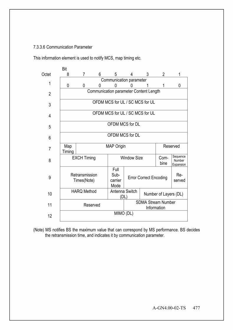
A-GN4.00-02-TS 477
7.3.3.6 Communication Parameter This information element is used to notify MCS, map timing etc.
Bit Octet 8 7 6 5 4 3 2 1
1 Communication parameter
0 0 0 0 0 1 1 0
2 Communication parameter Content Length
3 OFDM MCS for UL / SC MCS for UL
4 OFDM MCS for UL / SC MCS for UL
5 OFDM MCS for DL
6 OFDM MCS for DL
7 Map Timing
MAP Origin
Reserved
8 EXCH Timing
Window Size
Com- bine
Sequence Number
Expansion
9 Retransmission Times(Note)
Full Sub-
carrier Mode
Error Correct Encoding Re- served
10 HARQ Method
Antenna Switch (DL) Number of Layers (DL)
11 Reserved SDMA Stream Number Information
12 MIMO (DL)
(Note) MS notifies BS the maximum value that can correspond by MS performance. BS decides
the retransmission time, and indicates it by communication parameter.
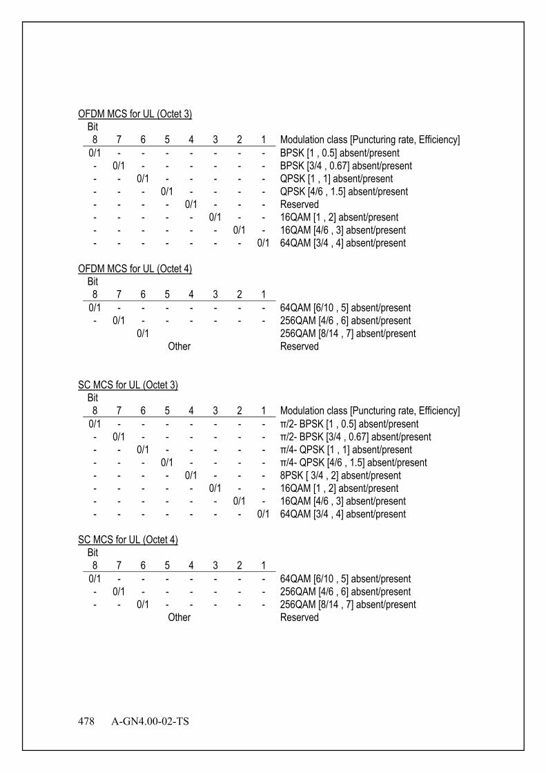
478 A-GN4.00-02-TS
OFDM MCS for UL (Octet 3)
Bit 8 7 6 5 4 3 2 1 Modulation class [Puncturing rate, Efficiency]
0/1 - - - - - - - BPSK [1 , 0.5] absent/present - 0/1 - - - - - - BPSK [3/4 , 0.67] absent/present - - 0/1 - - - - - QPSK [1 , 1] absent/present - - - 0/1 - - - - QPSK [4/6 , 1.5] absent/present - - - - 0/1 - - - Reserved - - - - - 0/1 - - 16QAM [1 , 2] absent/present - - - - - - 0/1 - 16QAM [4/6 , 3] absent/present - - - - - - - 0/1 64QAM [3/4 , 4] absent/present
OFDM MCS for UL (Octet 4)
Bit 8 7 6 5 4 3 2 1
0/1 - - - - - - - 64QAM [6/10 , 5] absent/present - 0/1 - - - - - - 256QAM [4/6 , 6] absent/present 0/1 256QAM [8/14 , 7] absent/present
Other Reserved SC MCS for UL (Octet 3)
Bit 8 7 6 5 4 3 2 1 Modulation class [Puncturing rate, Efficiency]
0/1 - - - - - - - π/2- BPSK [1 , 0.5] absent/present - 0/1 - - - - - - π/2- BPSK [3/4 , 0.67] absent/present - - 0/1 - - - - - π/4- QPSK [1 , 1] absent/present - - - 0/1 - - - - π/4- QPSK [4/6 , 1.5] absent/present - - - - 0/1 - - - 8PSK [ 3/4 , 2] absent/present - - - - - 0/1 - - 16QAM [1 , 2] absent/present - - - - - - 0/1 - 16QAM [4/6 , 3] absent/present - - - - - - - 0/1 64QAM [3/4 , 4] absent/present
SC MCS for UL (Octet 4)
Bit 8 7 6 5 4 3 2 1
0/1 - - - - - - - 64QAM [6/10 , 5] absent/present - 0/1 - - - - - - 256QAM [4/6 , 6] absent/present - - 0/1 - - - - - 256QAM [8/14 , 7] absent/present
Other Reserved
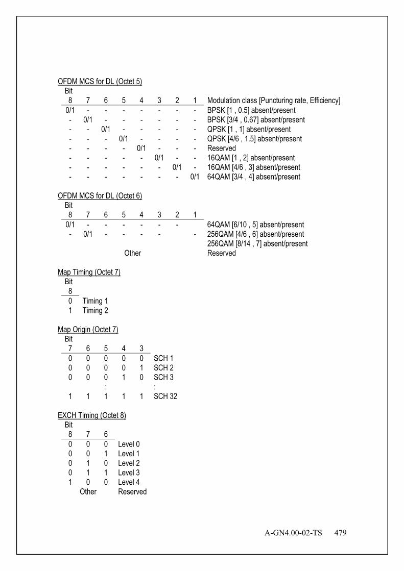
A-GN4.00-02-TS 479
OFDM MCS for DL (Octet 5)
Bit 8 7 6 5 4 3 2 1 Modulation class [Puncturing rate, Efficiency]
0/1 - - - - - - - BPSK [1 , 0.5] absent/present - 0/1 - - - - - - BPSK [3/4 , 0.67] absent/present - - 0/1 - - - - - QPSK [1 , 1] absent/present - - - 0/1 - - - - QPSK [4/6 , 1.5] absent/present - - - - 0/1 - - - Reserved - - - - - 0/1 - - 16QAM [1 , 2] absent/present - - - - - - 0/1 - 16QAM [4/6 , 3] absent/present - - - - - - - 0/1 64QAM [3/4 , 4] absent/present
OFDM MCS for DL (Octet 6)
Bit 8 7 6 5 4 3 2 1
0/1 - - - - - - 64QAM [6/10 , 5] absent/present - 0/1 - - - - - 256QAM [4/6 , 6] absent/present 256QAM [8/14 , 7] absent/present
Other Reserved Map Timing (Octet 7)
Bit 8 0 Timing 1 1 Timing 2
Map Origin (Octet 7)
Bit 7 6 5 4 3 0 0 0 0 0 SCH 1 0 0 0 0 1 SCH 2 0 0 0 1 0 SCH 3
: : 1 1 1 1 1 SCH 32
EXCH Timing (Octet 8)
Bit 8 7 6 0 0 0 Level 0 0 0 1 Level 1 0 1 0 Level 2 0 1 1 Level 3 1 0 0 Level 4
Other Reserved
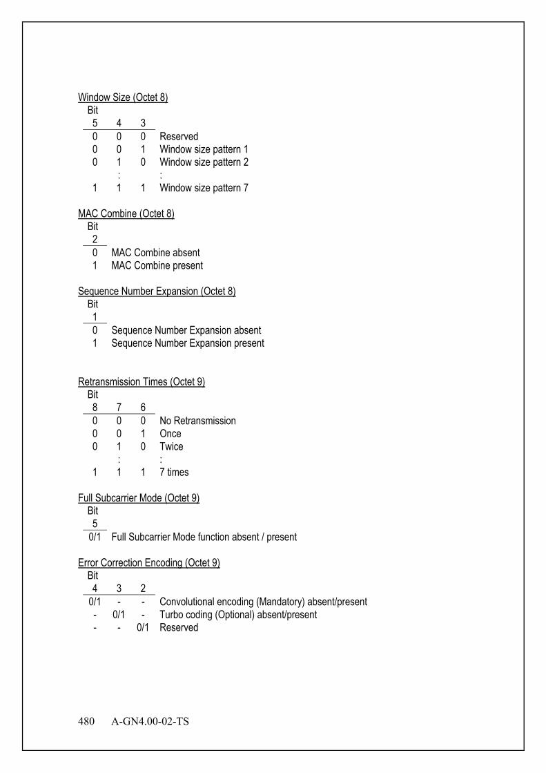
480 A-GN4.00-02-TS
Window Size (Octet 8) Bit 5 4 3 0 0 0 Reserved 0 0 1 Window size pattern 1 0 1 0 Window size pattern 2
: : 1 1 1 Window size pattern 7
MAC Combine (Octet 8)
Bit 2 0 MAC Combine absent 1 MAC Combine present
Sequence Number Expansion (Octet 8)
Bit 1 0 Sequence Number Expansion absent 1 Sequence Number Expansion present
Retransmission Times (Octet 9)
Bit 8 7 6 0 0 0 No Retransmission 0 0 1 Once 0 1 0 Twice
: : 1 1 1 7 times
Full Subcarrier Mode (Octet 9)
Bit 5
0/1 Full Subcarrier Mode function absent / present Error Correction Encoding (Octet 9)
Bit 4 3 2
0/1 - - Convolutional encoding (Mandatory) absent/present - 0/1 - Turbo coding (Optional) absent/present - - 0/1 Reserved
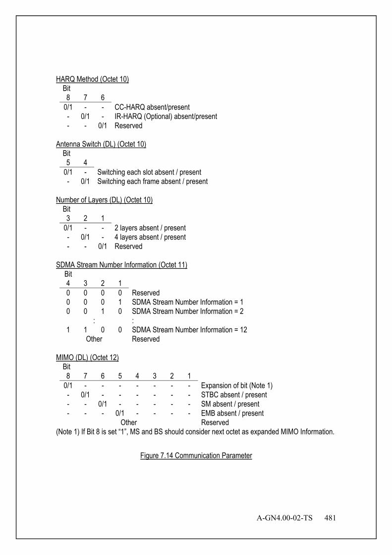
A-GN4.00-02-TS 481
HARQ Method (Octet 10)
Bit 8 7 6
0/1 - - CC-HARQ absent/present - 0/1 - IR-HARQ (Optional) absent/present - - 0/1 Reserved
Antenna Switch (DL) (Octet 10)
Bit 5 4
0/1 - Switching each slot absent / present - 0/1 Switching each frame absent / present
Number of Layers (DL) (Octet 10)
Bit 3 2 1
0/1 - - 2 layers absent / present - 0/1 - 4 layers absent / present - - 0/1 Reserved
SDMA Stream Number Information (Octet 11)
Bit 4 3 2 1 0 0 0 0 Reserved 0 0 0 1 SDMA Stream Number Information = 1 0 0 1 0 SDMA Stream Number Information = 2
: : 1 1 0 0 SDMA Stream Number Information = 12
Other Reserved MIMO (DL) (Octet 12)
Bit 8 7 6 5 4 3 2 1
0/1 - - - - - - - Expansion of bit (Note 1) - 0/1 - - - - - - STBC absent / present - - 0/1 - - - - - SM absent / present - - - 0/1 - - - - EMB absent / present
Other Reserved (Note 1) If Bit 8 is set “1”, MS and BS should consider next octet as expanded MIMO Information.
Figure 7.14 Communication Parameter

482 A-GN4.00-02-TS
7.3.3.7 Connection-ID This information element is used to notify connection-ID.
Bit Octet 8 7 6 5 4 3 2 1
1 Connection-ID
0 0 0 0 0 1 1 1
2 Connection-ID Content Length
3 Connection-ID
Reserved
Connection-ID (Octet 3)
Bit 8 7 6 5 0 0 0 0 Connection-ID 1 0 0 0 1 Connection-ID 2 0 0 1 0 Connection-ID 3
: : 1 1 1 1 Connection-ID 16
Figure 7.15 Connection-ID
7.3.3.8 CQI This information element is used to notify the CQI to BS that is measured by MS.
Bit Octet 8 7 6 5 4 3 2 1
1 CQI
0 0 0 0 1 0 0 0
2 CQI Content Length
3 RMAP (MSB)
: :
11 RMAP (LSB)
12 MAP Origin
Reserved
RMAP is the number based on MAP origin. MS notifies the status of PRU as CQI, as requested by BS. CQI information is composed of RMAP. RMAP notifies the status of PRU.
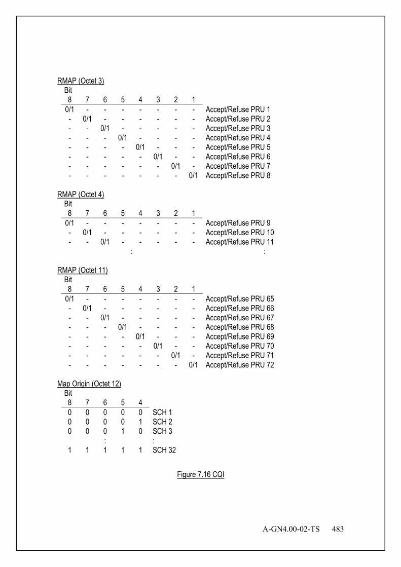
A-GN4.00-02-TS 483
RMAP (Octet 3)
Bit 8 7 6 5 4 3 2 1
0/1 - - - - - - - Accept/Refuse PRU 1 - 0/1 - - - - - - Accept/Refuse PRU 2 - - 0/1 - - - - - Accept/Refuse PRU 3 - - - 0/1 - - - - Accept/Refuse PRU 4 - - - - 0/1 - - - Accept/Refuse PRU 5 - - - - - 0/1 - - Accept/Refuse PRU 6 - - - - - - 0/1 - Accept/Refuse PRU 7 - - - - - - - 0/1 Accept/Refuse PRU 8
RMAP (Octet 4)
Bit 8 7 6 5 4 3 2 1
0/1 - - - - - - - Accept/Refuse PRU 9 - 0/1 - - - - - - Accept/Refuse PRU 10 - - 0/1 - - - - - Accept/Refuse PRU 11
: : RMAP (Octet 11)
Bit 8 7 6 5 4 3 2 1
0/1 - - - - - - - Accept/Refuse PRU 65 - 0/1 - - - - - - Accept/Refuse PRU 66 - - 0/1 - - - - - Accept/Refuse PRU 67 - - - 0/1 - - - - Accept/Refuse PRU 68 - - - - 0/1 - - - Accept/Refuse PRU 69 - - - - - 0/1 - - Accept/Refuse PRU 70 - - - - - - 0/1 - Accept/Refuse PRU 71 - - - - - - - 0/1 Accept/Refuse PRU 72
Map Origin (Octet 12)
Bit 8 7 6 5 4 0 0 0 0 0 SCH 1 0 0 0 0 1 SCH 2 0 0 0 1 0 SCH 3
: : 1 1 1 1 1 SCH 32
Figure 7.16 CQI
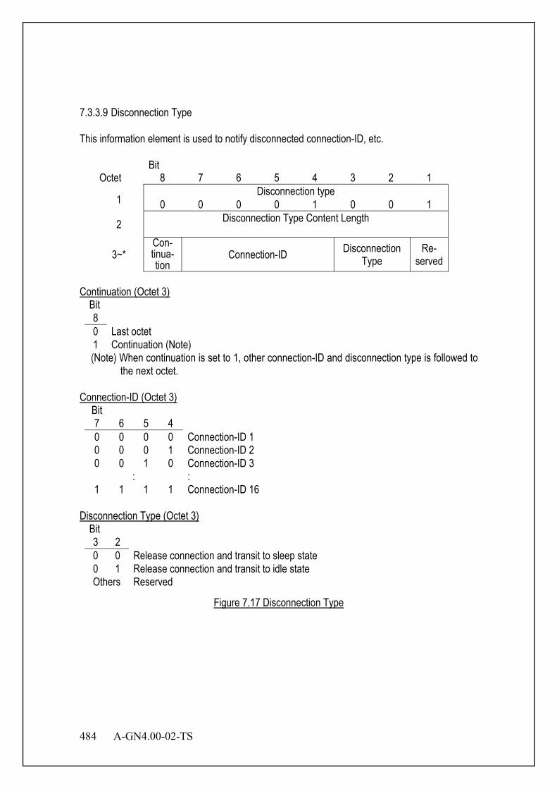
484 A-GN4.00-02-TS
7.3.3.9 Disconnection Type This information element is used to notify disconnected connection-ID, etc.
Bit Octet 8 7 6 5 4 3 2 1
1 Disconnection type
0 0 0 0 1 0 0 1
2 Disconnection Type Content Length
3~* Con- tinua- tion
Connection-ID Disconnection Type
Re- served
Continuation (Octet 3)
Bit 8 0 Last octet 1 Continuation (Note) (Note) When continuation is set to 1, other connection-ID and disconnection type is followed to
the next octet. Connection-ID (Octet 3)
Bit 7 6 5 4 0 0 0 0 Connection-ID 1 0 0 0 1 Connection-ID 2 0 0 1 0 Connection-ID 3
: : 1 1 1 1 Connection-ID 16
Disconnection Type (Octet 3)
Bit 3 2 0 0 Release connection and transit to sleep state 0 1 Release connection and transit to idle state Others Reserved
Figure 7.17 Disconnection Type
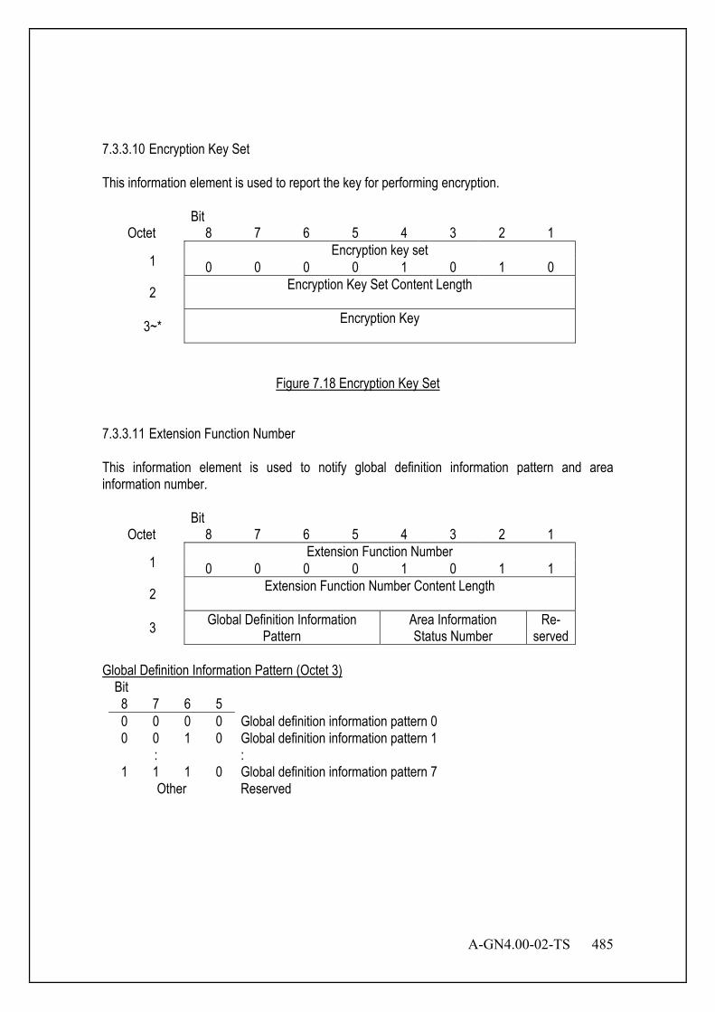
A-GN4.00-02-TS 485
7.3.3.10 Encryption Key Set This information element is used to report the key for performing encryption.
Bit Octet 8 7 6 5 4 3 2 1
1 Encryption key set
0 0 0 0 1 0 1 0
2 Encryption Key Set Content Length
3~* Encryption Key
Figure 7.18 Encryption Key Set
7.3.3.11 Extension Function Number This information element is used to notify global definition information pattern and area information number.
Bit Octet 8 7 6 5 4 3 2 1
1 Extension Function Number
0 0 0 0 1 0 1 1
2 Extension Function Number Content Length
3 Global Definition Information Pattern
Area Information Status Number
Re- served
Global Definition Information Pattern (Octet 3)
Bit 8 7 6 5 0 0 0 0 Global definition information pattern 0 0 0 1 0 Global definition information pattern 1 : : 1 1 1 0 Global definition information pattern 7
Other Reserved

486 A-GN4.00-02-TS
Area Information Status Number (Octet 3)
Bit 4 3 2 0 0 0 No area information 0 0 1 Area information status number 1
: : 1 1 1 Area information status number 7
Figure 7.19 Extension Function Number
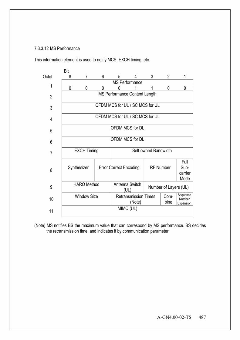
A-GN4.00-02-TS 487
7.3.3.12 MS Performance This information element is used to notify MCS, EXCH timing, etc.
Bit Octet 8 7 6 5 4 3 2 1
1 MS Performance
0 0 0 0 1 1 0 0
2 MS Performance Content Length
3 OFDM MCS for UL / SC MCS for UL
4 OFDM MCS for UL / SC MCS for UL
5 OFDM MCS for DL
6 OFDM MCS for DL
7 EXCH Timing
Self-owned Bandwidth
8 Synthesizer
Error Correct Encoding
RF Number
Full Sub-
carrier Mode
9 HARQ Method
Antenna Switch (UL) Number of Layers (UL)
10 Window Size
Retransmission Times (Note)
Com- bine
Sequence Number
Expansion 11 MIMO (UL)
(Note) MS notifies BS the maximum value that can correspond by MS performance. BS decides
the retransmission time, and indicates it by communication parameter.
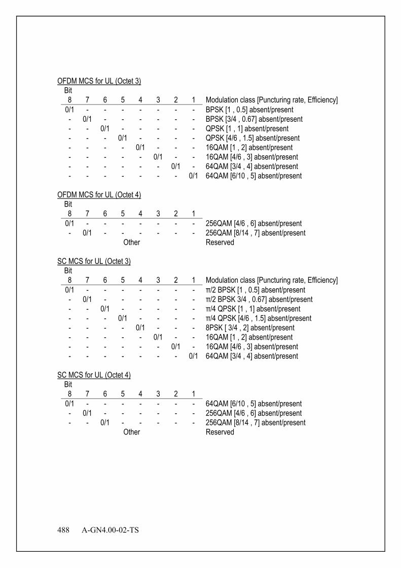
488 A-GN4.00-02-TS
OFDM MCS for UL (Octet 3)
Bit 8 7 6 5 4 3 2 1 Modulation class [Puncturing rate, Efficiency]
0/1 - - - - - - - BPSK [1 , 0.5] absent/present - 0/1 - - - - - - BPSK [3/4 , 0.67] absent/present - - 0/1 - - - - - QPSK [1 , 1] absent/present - - - 0/1 - - - - QPSK [4/6 , 1.5] absent/present - - - - 0/1 - - - 16QAM [1 , 2] absent/present - - - - - 0/1 - - 16QAM [4/6 , 3] absent/present - - - - - - 0/1 - 64QAM [3/4 , 4] absent/present - - - - - - - 0/1 64QAM [6/10 , 5] absent/present
OFDM MCS for UL (Octet 4)
Bit 8 7 6 5 4 3 2 1
0/1 - - - - - - - 256QAM [4/6 , 6] absent/present - 0/1 - - - - - - 256QAM [8/14 , 7] absent/present
Other Reserved SC MCS for UL (Octet 3)
Bit 8 7 6 5 4 3 2 1 Modulation class [Puncturing rate, Efficiency]
0/1 - - - - - - - π/2 BPSK [1 , 0.5] absent/present - 0/1 - - - - - - π/2 BPSK 3/4 , 0.67] absent/present - - 0/1 - - - - - π/4 QPSK [1 , 1] absent/present - - - 0/1 - - - - π/4 QPSK [4/6 , 1.5] absent/present - - - - 0/1 - - - 8PSK [ 3/4 , 2] absent/present - - - - - 0/1 - - 16QAM [1 , 2] absent/present - - - - - - 0/1 - 16QAM [4/6 , 3] absent/present - - - - - - - 0/1 64QAM [3/4 , 4] absent/present
SC MCS for UL (Octet 4)
Bit 8 7 6 5 4 3 2 1
0/1 - - - - - - - 64QAM [6/10 , 5] absent/present - 0/1 - - - - - - 256QAM [4/6 , 6] absent/present - - 0/1 - - - - - 256QAM [8/14 , 7] absent/present
Other Reserved
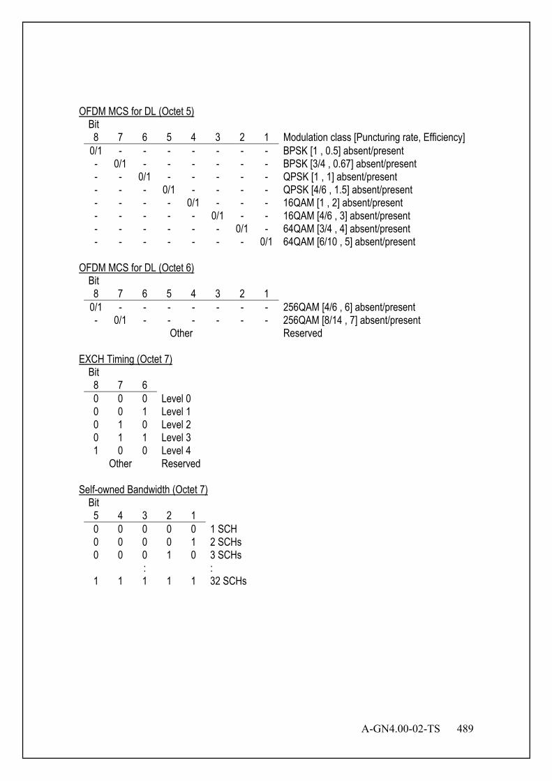
A-GN4.00-02-TS 489
OFDM MCS for DL (Octet 5)
Bit 8 7 6 5 4 3 2 1 Modulation class [Puncturing rate, Efficiency]
0/1 - - - - - - - BPSK [1 , 0.5] absent/present - 0/1 - - - - - - BPSK [3/4 , 0.67] absent/present - - 0/1 - - - - - QPSK [1 , 1] absent/present - - - 0/1 - - - - QPSK [4/6 , 1.5] absent/present - - - - 0/1 - - - 16QAM [1 , 2] absent/present - - - - - 0/1 - - 16QAM [4/6 , 3] absent/present - - - - - - 0/1 - 64QAM [3/4 , 4] absent/present - - - - - - - 0/1 64QAM [6/10 , 5] absent/present
OFDM MCS for DL (Octet 6)
Bit 8 7 6 5 4 3 2 1
0/1 - - - - - - - 256QAM [4/6 , 6] absent/present - 0/1 - - - - - - 256QAM [8/14 , 7] absent/present
Other Reserved EXCH Timing (Octet 7)
Bit 8 7 6 0 0 0 Level 0 0 0 1 Level 1 0 1 0 Level 2 0 1 1 Level 3 1 0 0 Level 4
Other Reserved Self-owned Bandwidth (Octet 7)
Bit 5 4 3 2 1 0 0 0 0 0 1 SCH 0 0 0 0 1 2 SCHs 0 0 0 1 0 3 SCHs
: : 1 1 1 1 1 32 SCHs

490 A-GN4.00-02-TS
Synthesizer (Octet 8)
Bit 8 7 0 0 No center frequency switching capability (Note 1) 0 1 Center frequency switching time class 1 (Note 2) 1 0 Center frequency switching time class 2 (Note 3) 1 1 Center frequency switching time class 3
(Note 1) BS shall always assign same band to the MS. (Note 2) When adjacent slots are used within/beyond a frame, BS shall assign same band to the
MS. (Note 3) When adjacent slots next to each other across the TX/RX or RX/TX switching timing are
used, BS shall assign same band to the MS. Error Correction Encoding (Octet 8)
Bit 6 5 4
0/1 - - Convolutional encoding (Mandatory) absent/present - 0/1 - Turbo coding (Optional) absent/present - - 0/1 Reserved
RF Number (Octet 8)
Bit 3 2 0 0 RF number 1 0 1 RF number 2 1 0 RF number 3 1 1 RF number 4
Full Subcarrier Mode (Octet 8)
Bit 1
0/1 Full Subcarrier Mode function absent / present

A-GN4.00-02-TS 491
HARQ Method (Octet 9)
Bit 8 7 6
0/1 - - CC-HARQ absent/present - 0/1 - IR-HARQ (Optional) absent/present - - 0/1 Reserved
Antenna Switch (UL) (Octet 9)
Bit 5 4
0/1 - Switching each slot absent / present - 0/1 Switching each frame absent / present
Number of Layers (UL) (Octet 9)
Bit 3 2 1
0/1 - - 2 layers absent / present - 0/1 - 4 layers absent / present - - 0/1 Reserved
Window Size (Octet 10)
Bit 8 7 6 0 0 0 Reserved 0 0 1 Window size pattern 1 0 1 0 Window size pattern 2
: : 1 1 1 Window size pattern 7
Retransmission Times (Octet 10)
Bit 5 4 3 0 0 0 No Retransmission 0 0 1 Once 0 1 0 Twice
: : 1 1 1 7 times
MAC Combine (Octet 10)
Bit 2 0 MAC Combine absent 1 MAC Combine present

492 A-GN4.00-02-TS
Sequence Number Expansion (Octet 10) Bit 1 0 Sequence Number Expansion absent 1 Sequence Number Expansion present
MIMO (UL) (Octet 11)
Bit 8 7 6 5 4 3 2 1
0/1 - - - - - - - Expansion bit (Note 1) - 0/1 - - - - - - STBC absent / present - - 0/1 - - - - - SM absent / present - - - 0/1 - - - - EMB absent / present
Other Reserved (Note 1) If Bit 8 is set “1”, MS and BS should consider next octet as expanded MIMO Information.
Figure 7.20 MS Performance
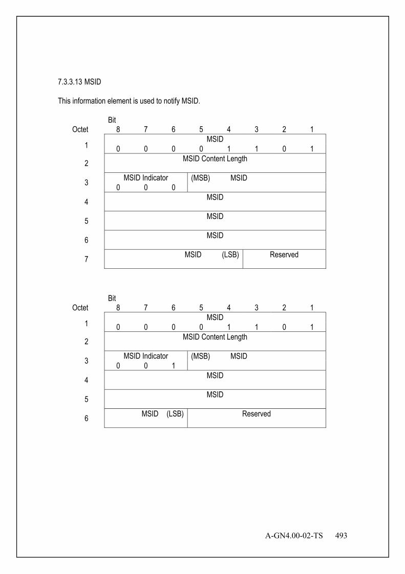
A-GN4.00-02-TS 493
7.3.3.13 MSID This information element is used to notify MSID.
Bit Octet 8 7 6 5 4 3 2 1
1 MSID
0 0 0 0 1 1 0 1
2 MSID Content Length
3 MSID Indicator (MSB) MSID 0 0 0
4 MSID
5 MSID
6 MSID
7 MSID (LSB)
Reserved
Bit Octet 8 7 6 5 4 3 2 1
1 MSID
0 0 0 0 1 1 0 1
2 MSID Content Length
3 MSID Indicator (MSB) MSID 0 0 1
4 MSID
5 MSID
6 MSID (LSB)
Reserved
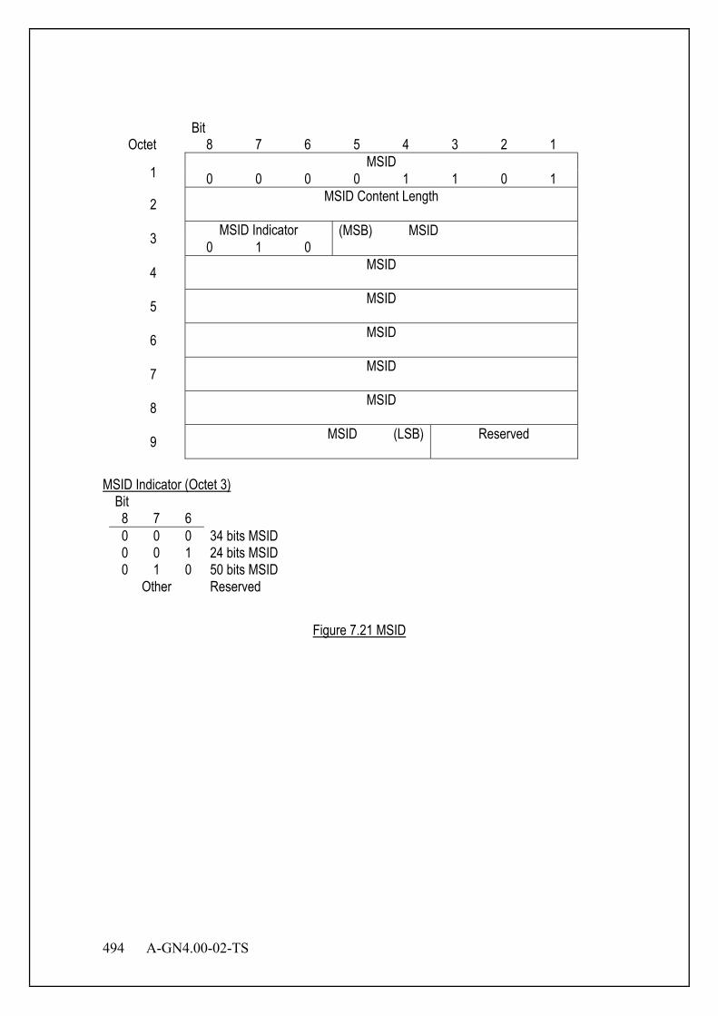
494 A-GN4.00-02-TS
Bit Octet 8 7 6 5 4 3 2 1
1 MSID
0 0 0 0 1 1 0 1
2 MSID Content Length
3 MSID Indicator (MSB) MSID 0 1 0
4 MSID
5 MSID
6 MSID
7 MSID
8 MSID
9 MSID (LSB)
Reserved
MSID Indicator (Octet 3)
Bit 8 7 6 0 0 0 34 bits MSID 0 0 1 24 bits MSID 0 1 0 50 bits MSID
Other Reserved
Figure 7.21 MSID

A-GN4.00-02-TS 495
7.3.3.14 Protocol Version This information element is used to notify protocol version.
Bit Octet 8 7 6 5 4 3 2 1
1 Protocol Version
0 0 0 0 1 1 1 0
2 Protocol Version Content Length
3 Protocol Version Number
Protocol Version Number (Octet 3)
Bit 8 7 6 5 4 3 2 1 - - - - - - - 0/1 Version 1 absent / present - - - - - - 0/1 - Version 2 absent / present
Other Reserved
Figure 7.22 Protocol Version
7.3.3.15 PRU Information This information element is used to specify additional PRU.
Bit Octet 8 7 6 5 4 3 2 1
1 PRU Information
0 0 0 0 1 1 1 1
2 PRU Information Content Length
3 Map
Timing (Note)
Map Origin (Note)
Reserved
4 PRU Number
Re- served
(Note) Map timing and map origin are considered to be undefined, when assign channel type in
“link setup request” message or “extension function response” message is CSCH.

496 A-GN4.00-02-TS
Map Timing (Octet 3)
Bit 8 0 Timing 1 1 Timing 2
Map Origin (Octet 3)
Bit 7 6 5 4 3 0 0 0 0 0 SCH 1 0 0 0 0 1 SCH 2 0 0 0 1 0 SCH 3
: : 1 1 1 1 1 SCH 32
PRU Number (Octet 4)
Bit 8 7 6 5 4 3 2 0 0 0 0 0 0 0 PRU 1 0 0 0 0 0 0 1 PRU 2 0 0 0 0 0 1 0 PRU 3
: : 1 1 1 1 1 1 1 PRU 128
Figure 7.23 PRU Information
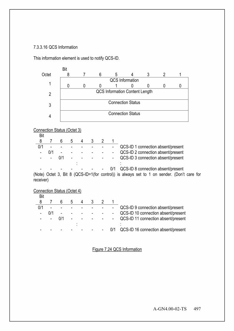
A-GN4.00-02-TS 497
7.3.3.16 QCS Information This information element is used to notify QCS-ID.
Bit Octet 8 7 6 5 4 3 2 1
1 QCS Information
0 0 0 1 0 0 0 0
2 QCS Information Content Length
3 Connection Status
4 Connection Status
Connection Status (Octet 3)
Bit 8 7 6 5 4 3 2 1
0/1 - - - - - - - QCS-ID 1 connection absent/present - 0/1 - - - - - - QCS-ID 2 connection absent/present - - 0/1 - - - - - QCS-ID 3 connection absent/present
: : - - - - - - - 0/1 QCS-ID 8 connection absent/present
(Note) Octet 3, Bit 8 (QCS-ID=1(for control)) is always set to 1 on sender. (Don’t care for receiver) Connection Status (Octet 4)
Bit 8 7 6 5 4 3 2 1
0/1 - - - - - - - QCS-ID 9 connection absent/present - 0/1 - - - - - - QCS-ID 10 connection absent/present - - 0/1 - - - - - QCS-ID 11 connection absent/present
: : - - - - - - - 0/1 QCS-ID 16 connection absent/present
Figure 7.24 QCS Information

498 A-GN4.00-02-TS
7.3.3.17 QoS This information element is used to notify QoS.
Bit Octet 8 7 6 5 4 3 2 1
1 QoS
0 0 0 1 0 0 0 1
2 QoS Content Length
3 Reserved
QoS Number
QoS Number (Octet 3)
Bit 4 3 2 1 0 0 0 0 LAC 0 0 0 1 PLC 0 0 1 0 nl-VRC 0 0 1 1 al-VRC 0 1 0 0 Ld-BE 0 1 1 0 Voice
Other Reserved
Figure 7.25 QoS
7.3.3.18 QCS Status This information element is used to notify QCS Status.
Bit Octet 8 7 6 5 4 3 2 1
1 QCS Status
0 0 0 1 0 0 1 0 2 QCS Status Content Length 3 QCS-ID Connection-ID 4 Reserved QoS Number 5 QCS-ID Connection-ID 6 Reserved QoS Number : :
33 QCS-ID Connection-ID 34 Reserved QoS Number
(Note) Omit the setting of QCS-ID=1 on sender. And receiver ignores setting of QCS-ID=1. (Note) Omit the setting of unused QCS(s).
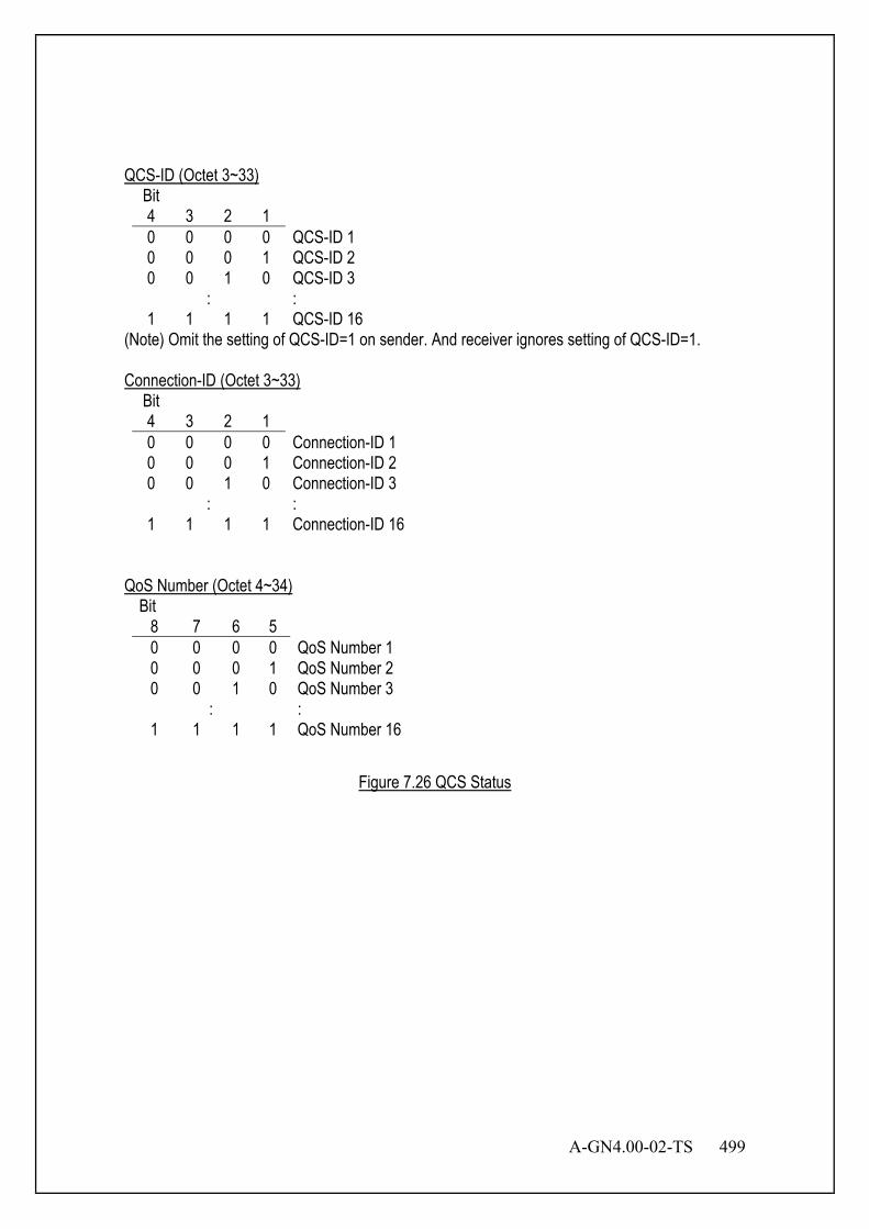
A-GN4.00-02-TS 499
QCS-ID (Octet 3~33)
Bit 4 3 2 1 0 0 0 0 QCS-ID 1 0 0 0 1 QCS-ID 2 0 0 1 0 QCS-ID 3
: : 1 1 1 1 QCS-ID 16
(Note) Omit the setting of QCS-ID=1 on sender. And receiver ignores setting of QCS-ID=1. Connection-ID (Octet 3~33)
Bit 4 3 2 1 0 0 0 0 Connection-ID 1 0 0 0 1 Connection-ID 2 0 0 1 0 Connection-ID 3
: : 1 1 1 1 Connection-ID 16
QoS Number (Octet 4~34)
Bit 8 7 6 5 0 0 0 0 QoS Number 1 0 0 0 1 QoS Number 2 0 0 1 0 QoS Number 3
: : 1 1 1 1 QoS Number 16
Figure 7.26 QCS Status
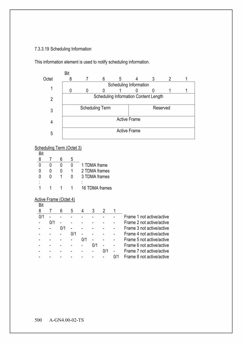
500 A-GN4.00-02-TS
7.3.3.19 Scheduling Information This information element is used to notify scheduling information.
Bit Octet 8 7 6 5 4 3 2 1
1 Scheduling Information
0 0 0 1 0 0 1 1
2 Scheduling Information Content Length
3 Scheduling Term
Reserved
4 Active Frame
5 Active Frame
Scheduling Term (Octet 3)
Bit 8 7 6 5 0 0 0 0 1 TDMA frame 0 0 0 1 2 TDMA frames 0 0 1 0 3 TDMA frames : : 1 1 1 1 16 TDMA frames
Active Frame (Octet 4)
Bit 8 7 6 5 4 3 2 1 0/1 - - - - - - - Frame 1 not active/active - 0/1 - - - - - - Frame 2 not active/active - - 0/1 - - - - - Frame 3 not active/active - - - 0/1 - - - - Frame 4 not active/active - - - - 0/1 - - - Frame 5 not active/active - - - - - 0/1 - - Frame 6 not active/active - - - - - - 0/1 - Frame 7 not active/active - - - - - - - 0/1 Frame 8 not active/active
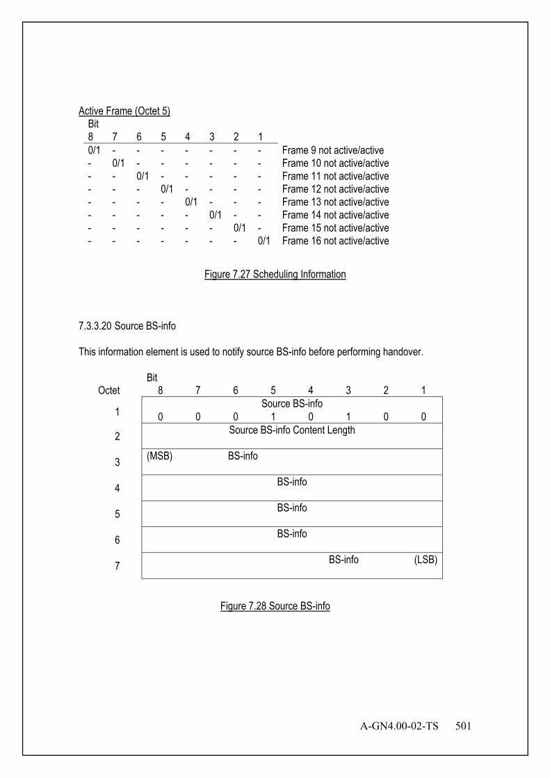
A-GN4.00-02-TS 501
Active Frame (Octet 5)
Bit 8 7 6 5 4 3 2 1 0/1 - - - - - - - Frame 9 not active/active - 0/1 - - - - - - Frame 10 not active/active - - 0/1 - - - - - Frame 11 not active/active - - - 0/1 - - - - Frame 12 not active/active - - - - 0/1 - - - Frame 13 not active/active - - - - - 0/1 - - Frame 14 not active/active - - - - - - 0/1 - Frame 15 not active/active - - - - - - - 0/1 Frame 16 not active/active
Figure 7.27 Scheduling Information
7.3.3.20 Source BS-info This information element is used to notify source BS-info before performing handover.
Bit Octet 8 7 6 5 4 3 2 1
1 Source BS-info
0 0 0 1 0 1 0 0
2 Source BS-info Content Length
3 (MSB) BS-info
4 BS-info
5 BS-info
6 BS-info
7 BS-info (LSB)
Figure 7.28 Source BS-info
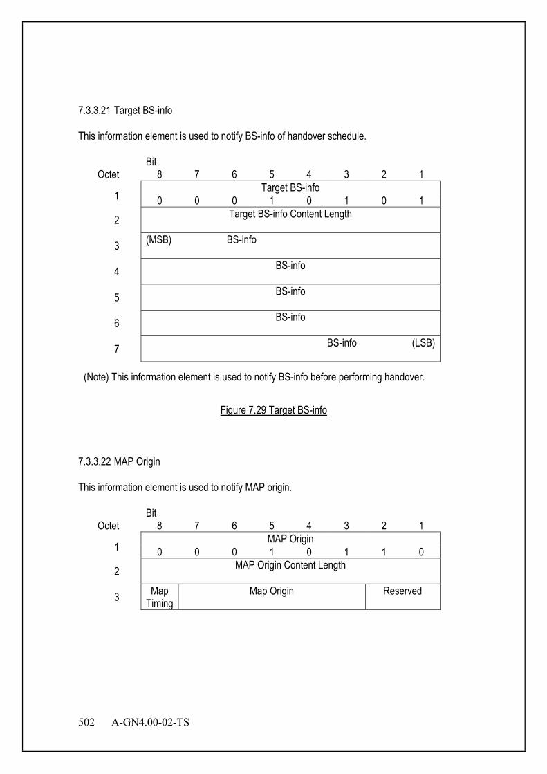
502 A-GN4.00-02-TS
7.3.3.21 Target BS-info This information element is used to notify BS-info of handover schedule.
Bit Octet 8 7 6 5 4 3 2 1
1 Target BS-info
0 0 0 1 0 1 0 1
2 Target BS-info Content Length
3 (MSB) BS-info
4 BS-info
5 BS-info
6 BS-info
7 BS-info (LSB)
(Note) This information element is used to notify BS-info before performing handover.
Figure 7.29 Target BS-info
7.3.3.22 MAP Origin This information element is used to notify MAP origin.
Bit Octet 8 7 6 5 4 3 2 1
1 MAP Origin
0 0 0 1 0 1 1 0
2 MAP Origin Content Length
3 Map Timing
Map Origin
Reserved

A-GN4.00-02-TS 503
Map Timing (Octet 3)
Bit 8 0 Timing 1 1 Timing 2
Map Origin (Octet 3)
Bit 7 6 5 4 3 0 0 0 0 0 SCH 1 0 0 0 0 1 SCH 2 0 0 0 1 0 SCH 3
: : 1 1 1 1 1 SCH 32
Figure 7.30 MAP Origin
7.3.3.23 MSID (SC) This information element is used to notify MSID in Link Setup Request (SC) message. This information element has particular structure in order to reduce the message size.
Bit Octet 8 7 6 5 4 3 2 1
1 Protocol version Number
2 MSID Indicator (MSB) MSID 0 0 0
3 MSID
4 MSID
5 MSID
6 MSID (LSB) Reserved
Start Indica-
tion
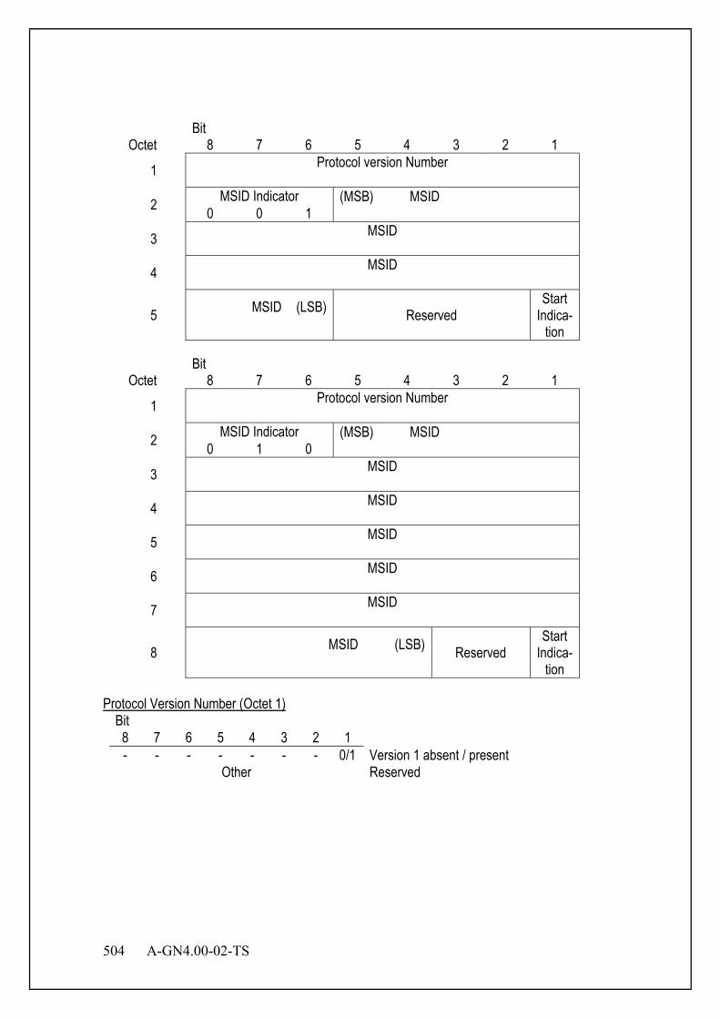
504 A-GN4.00-02-TS
Bit Octet 8 7 6 5 4 3 2 1
1 Protocol version Number
2 MSID Indicator (MSB) MSID 0 0 1
3 MSID
4 MSID
5 MSID (LSB) Reserved
Start Indica-
tion
Bit Octet 8 7 6 5 4 3 2 1
1 Protocol version Number
2 MSID Indicator (MSB) MSID 0 1 0
3 MSID
4 MSID
5 MSID
6 MSID
7 MSID
8 MSID (LSB) Reserved
Start Indica-
tion Protocol Version Number (Octet 1)
Bit 8 7 6 5 4 3 2 1 - - - - - - - 0/1 Version 1 absent / present
Other Reserved

A-GN4.00-02-TS 505
MSID Indicator (Octet 2)
Bit 8 7 6 0 0 0 34 bits MSID 0 0 1 24 bits MSID 0 1 0 50 bits MSID
Other Reserved Start Indication (Octet 6/5/8)
Bit 4 0 Extension function sequence absent 1 Extension function sequence present
Bit Octet 8 7 6 5 4 3 2 1
1 Protocol Version Number
0 0 0 1 0 1 1 0
2 MAP Origin Content Length
3 Map Timing
Map Origin
Reserved
Figure 7.31 MSID (SC)

506 A-GN4.00-02-TS
7.3.3.24 Power Report This information element is used to notify ANCH transmission power margin by MS.
Bit Octet 8 7 6 5 4 3 2 1
1 Power Report
0 0 0 1 0 1 1 1
2 Power Report Content Length
3 Transmission Power Margin
Transmission Power Margin (Octet 3)
Bit 8 7 6 5 4 3 2 1 0 0 0 0 0 0 0 0 0 dB 0 0 0 0 0 0 0 1 1 dB
: : 0 1 0 1 0 0 0 0 80 dB
Other Reserved (Note) 1dB unit
Figure 7.32 Power Report 7.3.3.25 Report Indication This information element is used to indicate of transmitting each CQI Report and Power Report, or both.
Bit Octet 8 7 6 5 4 3 2 1
1 Report Indication
0 0 0 1 1 0 0 0
2 Report Indication Content Length
3 Report
Indication Content
Reserved

A-GN4.00-02-TS 507
Report Indication Content (Octet 3)
Bit 8 7
0/1 - CQI Request absent/present - 0/1 Power Report Request absent/present
Figure 7.33 Report Indication
7.3.3.26 Encryption Key Information This information element is used to notify encryption key information.
Bit Octet 8 7 6 5 4 3 2 1
1 Encryption Key Information
0 0 0 1 1 0 0 1
2 Encryption Key Information Content Length
6 Key Lifetime
Key Lifetime (Octet 6) Key Lifetime notifies MS of encryption key lifetime.
Figure 7.34 Encryption Key Information 7.3.3.27 MIMO Information This information element is used to negotiate or change MIMO type for ANCH.
Bit Octet 8 7 6 5 4 3 2 1
1 MIMO Information
0 0 0 1 1 0 1 0
2 MIMO Information Content Length
3 ANCH MIMO (UL)
ANCH MIMO (DL)
SDMA Stream Number Information
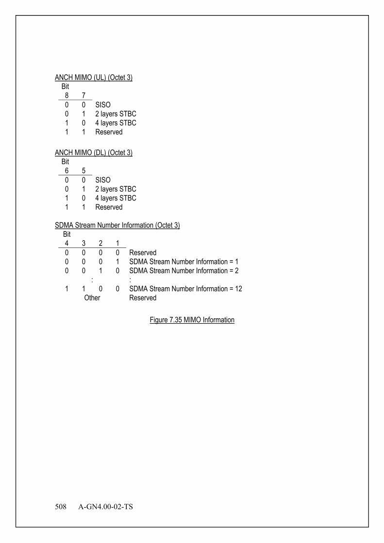
508 A-GN4.00-02-TS
ANCH MIMO (UL) (Octet 3)
Bit 8 7 0 0 SISO 0 1 2 layers STBC 1 0 4 layers STBC 1 1 Reserved
ANCH MIMO (DL) (Octet 3)
Bit 6 5 0 0 SISO 0 1 2 layers STBC 1 0 4 layers STBC 1 1 Reserved
SDMA Stream Number Information (Octet 3)
Bit 4 3 2 1 0 0 0 0 Reserved 0 0 0 1 SDMA Stream Number Information = 1 0 0 1 0 SDMA Stream Number Information = 2
: : 1 1 0 0 SDMA Stream Number Information = 12
Other Reserved
Figure 7.35 MIMO Information

A-GN4.00-02-TS 509
7.3.3.28 ICH Continuation Transmission Information This information element is used to start and stop ICH Continuation Transmission .
Bit Octet 8 7 6 5 4 3 2 1
1 ICH Continuation Transmission Information
0 0 0 1 1 0 1 1
2 ICH Continuation Transmission Information Content Length
3 ICH Transmission Times (UL) ICH Transmission Times (DL) ICH Transmission Times (UL) (Octet 3)
Bit 8 7 6 5 0 0 0 0 Once (disable) 0 0 0 1 Twice 0 0 1 0 ~ 1 0 0 1 10 times
Other Reserved ICH Retransmission times (DL) (Octet 3)
Bit 8 7 6 5 0 0 0 0 Once (disable) 0 0 0 1 Twice 0 0 1 0 ~ 1 0 0 1 10 times
Other Reserved
Figure 7.36 ICH Continuation Transmission Information

510 A-GN4.00-02-TS
7.3.4 Information Element Rules 7.3.4.1 Error process This section describes about error processing of messages and information elements in Access Establishment Phase Control. 7.3.4.1.1 Protocol Identifier When the message which has not protocol identifier “Access Establishment Phase Control” is received, receiver shall ignore the message. 7.3.4.1.2 Incomplete message When the message of which actual length is shorter than expected is received, receiver shall ignore the message. 7.3.4.1.3 Unexpected message type or message sequence error When unexpected message is received, receiver shall ignore the message and no state transition occurs. 7.3.4.1.4 Mandatory information element error 7.3.4.1.4.1 Missing mandatory information element When the message which does not include mandatory information element(s) is received, receiver shall ignore the message and no state transition occurs. 7.3.4.1.4.2 Invalid mandatory information element When the message which includes invalid mandatory information element(s) is received, the message shall be ignored at reception side, and no state transition carried out. When the message which has longer data length than expected one is received, reception side shall ignore extra content(s). When the message which has shorter data length than expected one is received, the message is identified as a message which contains contents error.
A-GN4.00-02-TS 511
7.3.4.1.4.3 Unexpected mandatory information element When the message which has unexpected mandatory information element(s) is received, receiver shall ignore the unexpected information element(s). Other information elements shall be adopted if they are expected ones. 7.3.4.1.4.4 Unrecognized mandatory information element When the message which has unrecognized mandatory information element(s) is received, receiver shall ignore the unrecognized information element(s). Other information elements shall be adopted if they are recognized one. 7.3.4.1.5 Optional information element error When a message which contains one or more invalid optional information elements is received, receiver acts only for information elements which contains valid contents. When a information element which has longer content length than expected one is received, the information element is valid until the content length which is expected. When a information element which has shorter content length than expected one is received, the information is recognized as error information element. 7.3.4.2 Information elements order This section describes about the order of each information element for message transmission and reception, as follows. <In case of message transmission> Information elements are set from smaller information element code. Single octet information element is judged by filling the lower four bits with zero. < In case of message reception > Receiver does not care information element order. (Note) Even if reception information elements are not set from smaller information element code, receiver always recognize as correct information elements.

512 A-GN4.00-02-TS
7.3.4.3 Duplicated information elements This section describes about the operation when duplicated information elements are set in the message, as follows. <In case of message reception> Receiver shall process only acceptable duplicated information elements from the top, and ignore subsequent unacceptable duplicated information elements. (Note) The number of duplication of information elements is only one in the current standard.
A-GN4.00-02-TS 513
Chapter 8 Sequence
8.1 Overview In this section, the standard control sequences between BS and MS are described. The names of messages transmitted and received between MS and BS are defined in Chapter 7. 8.2 Sequence 8.2.1 Outgoing Call Figure 8.1 shows sequence of an outgoing call. The control order is as follows: [1]LCH Assignment Request and Response
MS requests LCH assignment by transmitting “LCH assignment request“ message on TCCH to BS, and BS assigns a LCH by sending/transmitting “LCH assignment response” message on SCCH.
[2] Link Setup Request and Response MS performs carrier sensing for the assigned LCH channel. MS notifies the start of communication by sending/transmitting “link setup request” message when it judges that the assigned channel is not interfered and available. MS also notifies BS the communication ability, MSID etc in this message. BS notifies MS the function to use in this communication by sending/transmitting “link setup response” message.
[3] Extension Function Request and Response When the extra function of this LCH is necessary to be negotiated or changed, the content of the function change is notified by “extension function request and response” message. This message can be omitted if it is not necessary. It is notified with “extension function request” message when this message is necessary.
[4] Connection Request MS notifies the type of QoS connection to BS. The connection type in this case is outgoing call.
[5] Authentication The authentication information is transmitted between BS and MS when it is necessary in this sequence. The authentication method is not specified in this document.
[6] Encryption Key Indication BS transfers the encryption key to MS.
[7] Connection Response BS notifies MS Connection-ID, QCS information, etc.

514 A-GN4.00-02-TS
Figure 8.1 Outgoing Call Sequence
Note 1 When these control messages are transmitted with EDCH/CDCH/ICCH, the CD bit of the
MAC header is set as 00 or 01. Note 2 This is one example for the authentication sequence. Note 3 This message is optional. Note 4 When connection type is outgoing call with location registration, the sequence becomes a
similar sequence with that of an outgoing call. At this time, the result of location registration is notified with “connection response” message.
Note 5 In case of having received Connection Response message including MSID information element, MS shall use temporary ID value which is set in MSID information element afterwards.
MS BS
LCH Assignment Request TCCH LCH Assignment Response SCCH
Link Setup Request Link Setup Response
Extension Function Request Extension Function Response
Connection Request (outgoing call)
Authentication Information (1)
Encryption Key Indication
Connection Response
ICCH ICCH ICCH ICCH
ICCH/ ACCH EDCH/CDCH
Idle or Sleep State
Authentication Information (2)
(Note 1) (Note 2)
(Note 1)
(Note 1)
(Note 1) (Note 4) (Note 5)
(Note 1) (Note 2)
(Note 3) (Note 3)
Active State
Communication
ICCH/ ACCH EDCH/CDCH ICCH/ACCH EDCH/CDCH ICCH/ ACCH EDCH/CDCH ICCH/ ACCH EDCH/CDCH
A-GN4.00-02-TS 515
8.2.2 Incoming Call Figure 8.2 shows incoming call sequence. The control order is as follows: [1] Paging and LCH Assignment Request and Response
Paging message is sent on PCH from BS. MS requests LCH assignment to BS by sending “LCH assignment request“ message on TCCH, and BS assigns a LCH by sending “LCH assignment response” message on SCCH.
[2] Link Setup Request and Response MS performs carrier sensing for the assigned LCH channel. MS notifies the start of communication by sending “Link Setup Request” message when it judges that this assigned channel is not interfered and available. In this message, MS also notifies BS of the communication ability, MSID etc. BS notifies MS the function to use in this communication by sending “link setup response” message. [3] Extension Function Request and Response
When the extra function of this LCH is necessary to be negotiated or changed, the content of the function change is notified with “extension function request and response” message. This message can be omitted if it is not necessary. It is notified with “extension function request” message when this message is necessary.
[4] Connection Request MS notifies the type of QoS connection to BS. The connection type in this case is an incoming call.
[5] Authentication The authentication information is transmitted between BS and MS when it is necessary in this sequence. The authentication method is not specified in this document.
[6] Encryption Key Indication BS transfers the encryption key to MS.
[7] Connection Response BS notifies MS Connection-ID, QCS information, etc.

516 A-GN4.00-02-TS
Figure 8.2 Incoming Call Sequence
Note 1 When control data is transmitted with EDCH/CDCH/ICCH, the CD bit of the MAC header is set as 00 or 01.
Note 2 This is one example for the authentication sequence. Note 3 In case of having received Connection Response message including MSID information
element, MS shall use temporary ID value which is set in MSID information element afterwards.
MS BS
Paging PCH LCH Assignment Request TCCH
LCH Assignment Response SCCH
Link Setup Request Link Setup Response
Extension Function Request Extension Function Response
Connection Request (incoming)
Authentication Information (1)
Encryption Key Indication
Connection Response
ICCH ICCH ICCH ICCH
Authentication Information (2)
(Note 1) (Note 2)
(Note 1)
(Note 1)
(Note 1) (Note 3)
(Note 1) (Note 2)
Idle or Sleep State
Active State
Communication
ICCH/ ACCH EDCH/CDCH ICCH/ ACCH EDCH/CDCH ICCH/ ACCH EDCH/CDCH ICCH/ ACCH EDCH/CDCH ICCH/ ACCH EDCH/CDCH
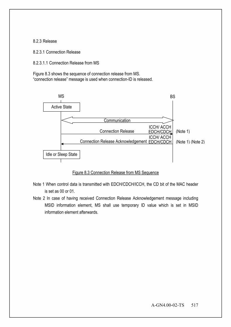
A-GN4.00-02-TS 517
8.2.3 Release 8.2.3.1 Connection Release 8.2.3.1.1 Connection Release from MS Figure 8.3 shows the sequence of connection release from MS. “connection release” message is used when connection-ID is released.
Figure 8.3 Connection Release from MS Sequence
Note 1 When control data is transmitted with EDCH/CDCH/ICCH, the CD bit of the MAC header is set as 00 or 01.
Note 2 In case of having received Connection Release Acknowledgement message including MSID information element, MS shall use temporary ID value which is set in MSID information element afterwards.
(Note 1)
(Note 1) (Note 2)
MS BS
Connection Release
Connection Release Acknowledgement
Idle or Sleep State
Active State
Communication
ICCH/ ACCH EDCH/CDCH
ICCH/ ACCH EDCH/CDCH
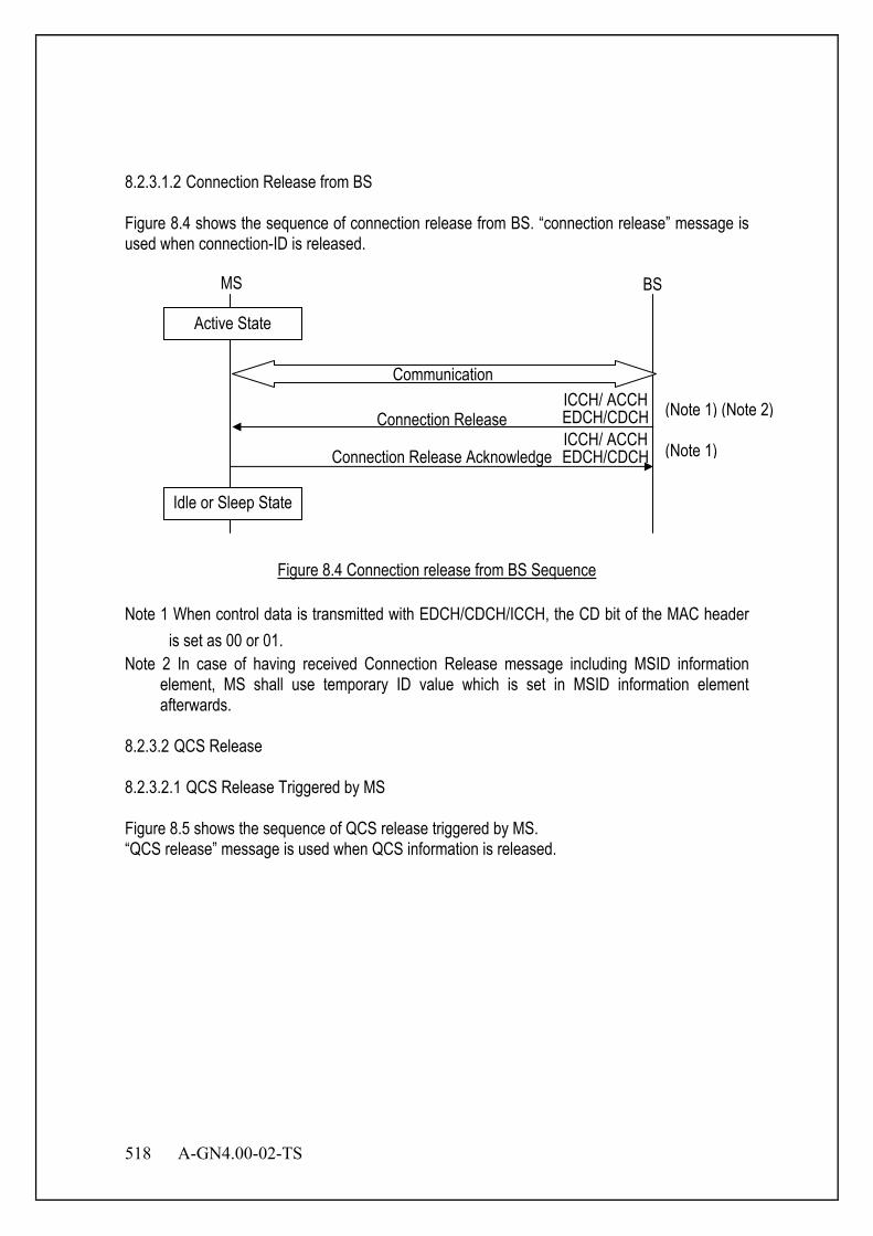
518 A-GN4.00-02-TS
8.2.3.1.2 Connection Release from BS Figure 8.4 shows the sequence of connection release from BS. “connection release” message is used when connection-ID is released.
Figure 8.4 Connection release from BS Sequence
Note 1 When control data is transmitted with EDCH/CDCH/ICCH, the CD bit of the MAC header is set as 00 or 01.
Note 2 In case of having received Connection Release message including MSID information element, MS shall use temporary ID value which is set in MSID information element afterwards.
8.2.3.2 QCS Release 8.2.3.2.1 QCS Release Triggered by MS Figure 8.5 shows the sequence of QCS release triggered by MS. “QCS release” message is used when QCS information is released.
MS BS
Connection Release
Connection Release Acknowledge
(Note 1) (Note 2)
(Note 1)
Idle or Sleep State
Active State
Communication
ICCH/ ACCH EDCH/CDCH
ICCH/ ACCH EDCH/CDCH
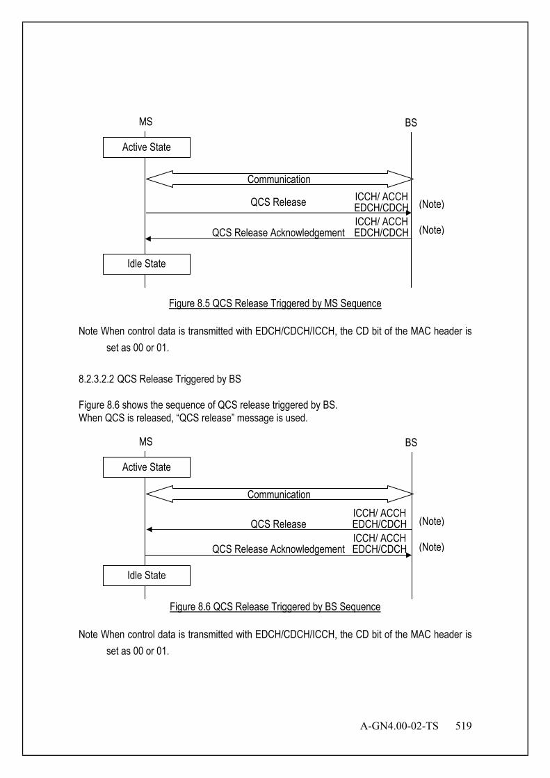
A-GN4.00-02-TS 519
Figure 8.5 QCS Release Triggered by MS Sequence
Note When control data is transmitted with EDCH/CDCH/ICCH, the CD bit of the MAC header is set as 00 or 01.
8.2.3.2.2 QCS Release Triggered by BS Figure 8.6 shows the sequence of QCS release triggered by BS. When QCS is released, “QCS release” message is used.
Figure 8.6 QCS Release Triggered by BS Sequence
Note When control data is transmitted with EDCH/CDCH/ICCH, the CD bit of the MAC header is set as 00 or 01.
MS BS
QCS Release
QCS Release Acknowledgement
Idle State
Active State
Communication
ICCH/ ACCH EDCH/CDCH
ICCH/ ACCH EDCH/CDCH (Note)
(Note)
MS BS
QCS Release
QCS Release Acknowledgement
Idle State
Active State
Communication
ICCH/ ACCH EDCH/CDCH
ICCH/ ACCH EDCH/CDCH (Note)
(Note)

520 A-GN4.00-02-TS
8.2.4 Location Registration Figure 8.7 shows the location registration sequence. Location registration is activated when MS moves to others paging area, or is powered at a different paging area. Home Location Register (HLR) control in network executes the location registration control. MS sends the location registration data on ICCH before the call connection. The control order is as follows: [1]LCH Assignment Request and Response
MS requests LCH assignment to BS by sending “LCH assignment request“ message on TCCH, and BS assigns a LCH by sending “LCH assignment response” message on SCCH.
[2] Link Setup Request and Response MS performs carrier sensing for the assigned LCH channel. MS notifies the start of communication by sending “link setup request” message when it judges that this assigned channel is not interfered and available. In this message, MS also notifies BS of the communication ability, MSID etc. BS notifies MS the function to use in this communication by sending “link setup response” message.
[3] Extension Function Request and Response When the extra function of this LCH is necessary to be negotiated or changed, the content of the function change is notified with “extension function request and response” message. This message can be omitted if it is not necessary. It is notified with “extension function request” message when this message is necessary.
[4] Connection Request MS notifies the kind of QoS connection to BS. The connection type in this case is “location registration”.
[5] Authentication The authentication information is transmitted between BS and MS when it is necessary in this sequence. The authentication method is not specified in this document.
[6] Encryption Key Indication BS transfers the encryption key to MS.
[7] Connection Response Connection-ID is omitted and the result of location registration is notified in a “connection response” message. Moreover, cause value in cause information element is set to no connection-ID, and connection is disconnected.

A-GN4.00-02-TS 521
Figure 8.7 Location Registration Sequence
Note 1 When control data is transmitted with EDCH/CDCH/ICCH, the CD bit of the MAC header is set as 00 or 01.
Note 2 This is one example for the authentication sequence. Note 3 Connection-ID is omitted when the result of location registration is notified. In addition,
cause value in cause information element is set to no connection-ID and connection is disconnected.
MS BS
LCH Assignment Request TCCH LCH Assignment Response SCCH
Link Setup Request Link Setup Response
Extension Function Request Extension Function Response
Connection Request (location registration)
Authentication Information (1)
Connection Response (location registration)
ICCH ICCH ICCH ICCH
Authentication Information (2)
(Note 1) (Note 2)
(Note 1)
(Note 1) (Note 2)
(Note 1) (Note 3)
Idle or Sleep State
Idle or Sleep State
ICCH/ ACCH EDCH/CDCH ICCH/ ACCH EDCH/CDCH ICCH/ ACCH EDCH/CDCH ICCH/ ACCH EDCH/CDCH
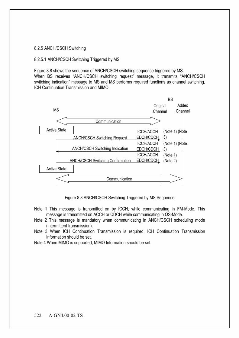
522 A-GN4.00-02-TS
8.2.5 ANCH/CSCH Switching 8.2.5.1 ANCH/CSCH Switching Triggered by MS Figure 8.8 shows the sequence of ANCH/CSCH switching sequence triggered by MS. When BS receives “ANCH/CSCH switching request” message, it transmits “ANCH/CSCH switching indication” message to MS and MS performs required functions as channel switching, ICH Continuation Transmission and MIMO.
BSAdded
ChannelMS
ANCH/CSCH Switching Request
ANCH/CSCH Switching Indication
ANCH/CSCH Switching Confirmation(Note 1)(Note 2)
Active State
Active State
Communication
OriginalChannel
ICCH/ACCHEDCH/CDCHICCH/ACCHEDCH/CDCHICCH/ACCHEDCH/CDCH
Communication
(Note 1) (Note3)(Note 1) (Note3)
Figure 8.8 ANCH/CSCH Switching Triggered by MS Sequence
Note 1 This message is transmitted on by ICCH, while communicating in FM-Mode. This message is transmitted on ACCH or CDCH while communicating in QS-Mode.
Note 2 This message is mandatory when communicating in ANCH/CSCH scheduling mode (intermittent transmission).
Note 3 When ICH Continuation Transmission is required, ICH Continuation Transmission Information should be set.
Note 4 When MIMO is supported, MIMO Information should be set.
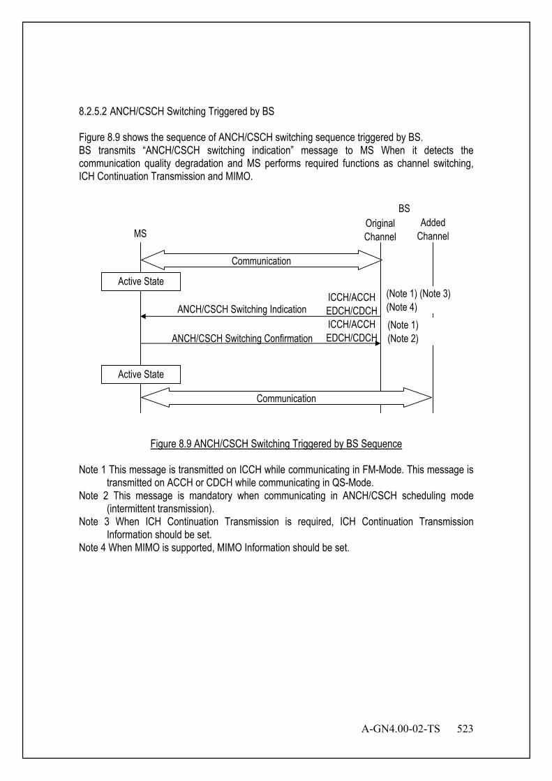
A-GN4.00-02-TS 523
8.2.5.2 ANCH/CSCH Switching Triggered by BS Figure 8.9 shows the sequence of ANCH/CSCH switching sequence triggered by BS. BS transmits “ANCH/CSCH switching indication” message to MS When it detects the communication quality degradation and MS performs required functions as channel switching, ICH Continuation Transmission and MIMO.
BSAdded
ChannelMS
ANCH/CSCH Switching Indication
ANCH/CSCH Switching Confirmation(Note 1)(Note 2)
Active State
Active State
Communication
OriginalChannel
ICCH/ACCHEDCH/CDCHICCH/ACCHEDCH/CDCH
(Note 1) (Note 3)(Note 4)
Communication
Figure 8.9 ANCH/CSCH Switching Triggered by BS Sequence
Note 1 This message is transmitted on ICCH while communicating in FM-Mode. This message is transmitted on ACCH or CDCH while communicating in QS-Mode.
Note 2 This message is mandatory when communicating in ANCH/CSCH scheduling mode (intermittent transmission).
Note 3 When ICH Continuation Transmission is required, ICH Continuation Transmission Information should be set.
Note 4 When MIMO is supported, MIMO Information should be set.

524 A-GN4.00-02-TS
8.2.5.3 ANCH/CSCH Switching Rejection Figure 8.10 shows the sequence of ANCH/CSCH switching rejection sequence. BS transmits “ANCH/CSCH switching rejection” message to MS when BS receive “ANCH/CSCH switching request“ message from MS.
BSAdded
ChannelMS
ANCH/CSCH Switching Indication
ANCH/CSCH Switching Rejection (Note 1)
Active State
Active State
Communication
OriginalChannel
ICCH/ACCHEDCH/CDCHICCH/ACCHEDCH/CDCH
(Note 1) (Note2)
Communication
Figure 8.10 ANCH/CSCH Switching Rejection Sequence
Note 1 This message is transmitted on ICCH while communicating in FM-Mode. This message is
transmitted on with ACCH or CDCH while communicating in QS-Mode. Note 2 When ICH Continuation Transmission is required, ICH Continuation Transmission
Information should be set. Note 3 When MIMO is supported, MIMO Information should be set.
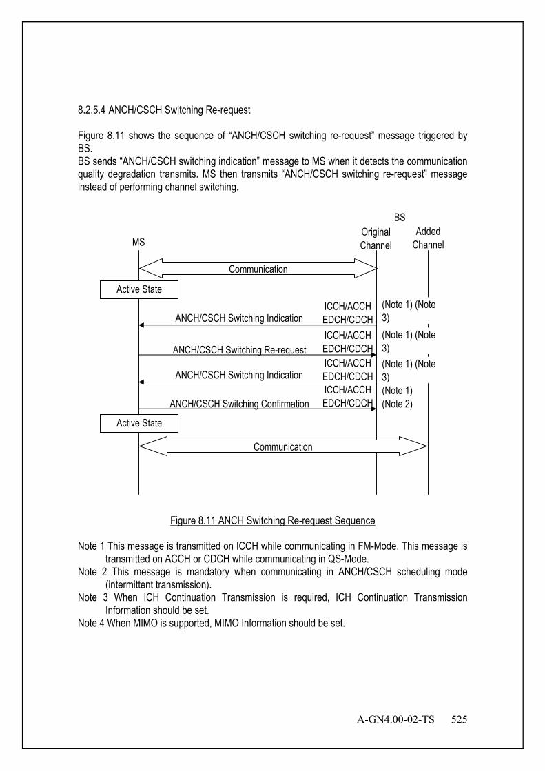
A-GN4.00-02-TS 525
8.2.5.4 ANCH/CSCH Switching Re-request Figure 8.11 shows the sequence of “ANCH/CSCH switching re-request” message triggered by BS. BS sends “ANCH/CSCH switching indication” message to MS when it detects the communication quality degradation transmits. MS then transmits “ANCH/CSCH switching re-request” message instead of performing channel switching.
BSAdded
ChannelMS
ANCH/CSCH Switching Re-request
ANCH/CSCH Switching Indication
ANCH/CSCH Switching Confirmation(Note 1)(Note 2)
Active State
Active State
Communication
OriginalChannel
ICCH/ACCHEDCH/CDCHICCH/ACCHEDCH/CDCHICCH/ACCHEDCH/CDCH
Communication
ANCH/CSCH Switching IndicationICCH/ACCHEDCH/CDCH
(Note 1) (Note3)(Note 1) (Note3)(Note 1) (Note3)
Figure 8.11 ANCH Switching Re-request Sequence
Note 1 This message is transmitted on ICCH while communicating in FM-Mode. This message is transmitted on ACCH or CDCH while communicating in QS-Mode.
Note 2 This message is mandatory when communicating in ANCH/CSCH scheduling mode (intermittent transmission).
Note 3 When ICH Continuation Transmission is required, ICH Continuation Transmission Information should be set.
Note 4 When MIMO is supported, MIMO Information should be set.
526 A-GN4.00-02-TS
8.2.6 Handover 8.2.6.1 Normal Handover Triggered by BS Figure 8.12 shows the normal handover sequence triggered by BS. The control order is as follows: [1] ANCH/CSCH Switching Request and Response
BS sends “ANCH/CSCH switching indication” message and indicates handover on detecting the communication quality degradation. MS shuts down the power and conduct transmission on receiving “ANCH/CSCH switching indication” message.
[2]LCH Assignment Request and Response MS requests LCH assignment to BS by sending “LCH assignment request” message on TCCH, and BS assigns a LCH by sending “LCH assignment response” message on SCCH.
[3] Link Setup Request and Response MS performs carrier sensing for the assigned LCH channel. MS notifies start of the communication by sending “link setup request” message when it judges that this assigned channel is not interfered and available. In this message, MS also notifies BS of the communication ability, MSID etc. BS notifies MS of the function to use in this communication by sending “link setup response” message.
[4] Extension Function Request and Response When the extra function of this LCH is necessary to be negotiated or changed, the content of the function change is notified with “extension function request and response” message. This message can be omitted if it is not necessary. It is notified with “extension function request” message when necessary.
[5] Connection Request MS notifies the type of QoS connection to BS. The connection type in this case is handover.
[6] Authentication The authentication information is transmitted between BS and MS when it is necessary in this sequence. The authentication method is not specified in this document.
[7] Encryption Key Indication BS transfers the encryption key to MS.
[8] Connection Response BS notifies MS of Connection-ID, QCS information, etc.
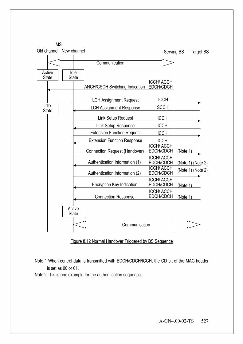
A-GN4.00-02-TS 527
Figure 8.12 Normal Handover Triggered by BS Sequence
Note 1 When control data is transmitted with EDCH/CDCH/ICCH, the CD bit of the MAC header
is set as 00 or 01. Note 2 This is one example for the authentication sequence.
MS
ANCH/CSCH Switching Indication
Serving BS Target BS
LCH Assignment Request TCCH LCH Assignment Response SCCH
Link Setup Request Link Setup Response
Extension Function Request Extension Function Response
Connection Request (Handover)
Authentication Information (1)
Encryption Key Indication
Connection Response
ICCH ICCH ICCH ICCH
Authentication Information (2)
(Note 1) (Note 2)
(Note 1)
(Note 1)
(Note 1)
(Note 1) (Note 2)
Communication
Communication
Active State
Old channel New channel
Idle State
Idle State
Active State
ICCH/ ACCH EDCH/CDCH ICCH/ ACCH EDCH/CDCH ICCH/ ACCH EDCH/CDCH ICCH/ ACCH EDCH/CDCH ICCH/ ACCH EDCH/CDCH
ICCH/ ACCH EDCH/CDCH

528 A-GN4.00-02-TS
8.2.6.2 Normal Handover Triggered by MS Figure 8.13 shows the normal handover sequence triggered by MS. The control order is as follows: [1] ANCH/CSCH Switching Request and Response
MS sends “ANCH/CSCH switching request“ message when it detects the communication quality degradation, and BS indicates handover by sending “ANCH/CSCH switching indication“ message. MS shuts down the power and conduct transmission on receiving “ANCH/CSCH switching indication“ message.
[2] LCH Assignment Request and Response MS requests LCH assignment to BS by sending “LCH assignment request“ message on TCCH, and BS assigns a LCH by sending “LCH assignment response” message on SCCH.
[3] Link Setup Request and Response MS performs carrier sensing for the assigned LCH channel. When MS notifies the start of communication by sending “link setup request” message when it judges that this assigned channel is not interfered and available. In this message, MS also notifies BS of the communication ability, MSID etc. BS notifies MS of the function to use in this communication by sending “link setup response” message.
[4] Extension Function Request and Response When the extra function of this LCH is necessary to be negotiated or changed, the content of the function change is notified with “extension function request and response” message. This message can be omitted if it is not necessary. It is notified with “extension function request” message when necessary.
[5] Connection Request MS notifies the type of QoS connection to BS. The connection type in this case is handover.
[6] Authentication The authentication information is transmitted between BS and MS when it is necessary in this sequence. The authentication method is not specified in this document.
[7] Encryption Key Indication BS transfers the encryption key to MS.
[8] Connection Response BS notifies MS Connection-ID, QCS information, etc.
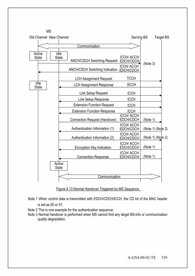
A-GN4.00-02-TS 529
Figure 8.13 Normal Handover Triggered by MS Sequence
Note 1 When control data is transmitted with EDCH/CDCH/ICCH, the CD bit of the MAC header is set as 00 or 01.
Note 2 This is one example for the authentication sequence. Note 3 Normal handover is performed when MS cannot find any target BS-info or communication
quality degradation.
MS Serving BS Target BS
ANCH/CSCH Switching Indication
ANCH/CSCH Switching Request
LCH Assignment Request TCCH LCH Assignment Response SCCH
Link Setup Request Link Setup Response
Extension Function Request Extension Function Response
Connection Request (Handover)
Authentication Information (1)
Encryption Key Indication
Connection Response
ICCH ICCH ICCH ICCH
Authentication Information (2)
(Note 1) (Note 2)
(Note 1)
(Note 1)
(Note 1)
(Note 1) (Note 2)
(Note 3)
Active State
Old Channel New Channel
Active State
Idle State
Idle State
Communication
Communication
ICCH/ ACCH EDCH/CDCH ICCH/ ACCH EDCH/CDCH ICCH/ ACCH EDCH/CDCH ICCH/ ACCH EDCH/CDCH ICCH/ ACCH EDCH/CDCH
ICCH/ ACCH EDCH/CDCH
ICCH/ ACCH EDCH/CDCH

530 A-GN4.00-02-TS
8.2.6.3 Seamless Handover Figure 8.14 shows the seamless handover sequence. The control order is as follows: [1]TDMA Slot Limitation Request
To search BS in the surrounding, MS transmits “TDMA slot limitation request“ message to BS and makes the slot vacant. Then MS searches for other BSs in the surrounding.
[2] ANCH/CSCH Switching Request and Response MS sends “ANCH/CSCH switching request“ message and indicates target BS to serving BS. Serving BS requests slot to target BS, and target BS responds slot to serving BS. Serving BS then sends “ANCH/CSCH switching indication” message to MS and indicates handover to target BS.
[3] LCH Assignment Request and Response MS requests LCH assignment to BS by sending “LCH assignment request“ message on TCCH, and BS assigns a LCH by sending “LCH assignment response” message on SCCH.
[4] Link Setup Request and Response MS performs carrier sensing for the assigned LCH channel. MS notifies the start of communication by sending “link setup request” message when it judges that this assigned channel is not interfered and available. In this message, MS also notifies BS of the communication ability, MSID etc. BS notifies MS of the function to use in this communication by sending “link setup response” message.
[5] Extension Function Request and Response When the extra function of this LCH is necessary to be negotiated or changed, the content of the function change is notified with “extension function request and response” message This message can be omitted if it is not necessary. It is notified with “extension function request” message when necessary.
[6] Connection Request MS notifies the type of QoS connection to BS. The connection type in this case is handover.
[7] Authentication The authentication information is transmitted between BS and MS when it is necessary in this sequence. The authentication method is not specified in this document.
[8] Encryption Key Indication BS transfers the encryption key to MS.
[9] Connection Response BS notifies MS of Connection-ID, QCS information, etc.
[10]Connection Release After MS performed handover and transited to the active state, MS or BS sends “connection release” message and radio connection is released.
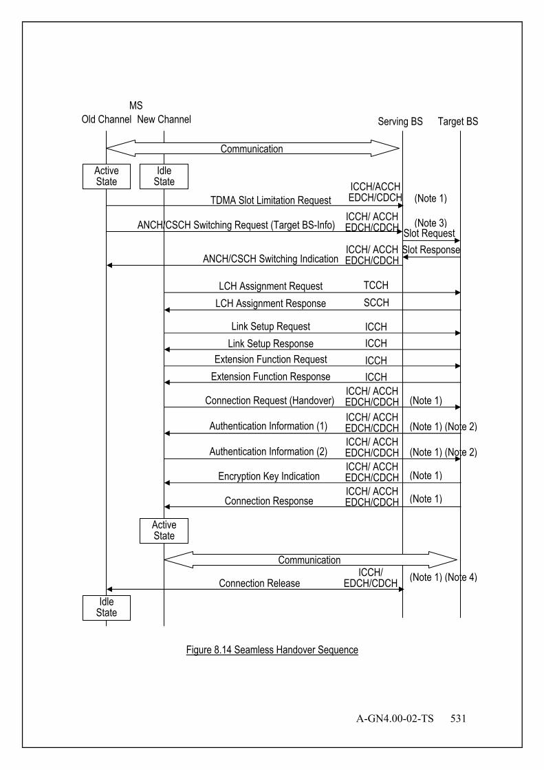
A-GN4.00-02-TS 531
Figure 8.14 Seamless Handover Sequence
Target BS MS
ANCH/CSCH Switching Indication
TDMA Slot Limitation Request
ANCH/CSCH Switching Request (Target BS-Info) Slot Request Slot Response
Serving BS
LCH Assignment Request TCCH LCH Assignment Response SCCH
Link Setup Request Link Setup Response
Extension Function Request Extension Function Response
Connection Request (Handover)
Authentication Information (1)
Encryption Key Indication
Connection Response
ICCH ICCH ICCH ICCH
Authentication Information (2)
(Note 1) (Note 2)
(Note 1)
(Note 1)
(Note 1)
(Note 1) (Note 2)
(Note 1)
(Note 3)
Connection Release (Note 1) (Note 4)
Active State
Old Channel New Channel
Active State
Idle State
Idle State
Communication
Communication
ICCH/ ACCH EDCH/CDCH ICCH/ ACCH EDCH/CDCH ICCH/ ACCH EDCH/CDCH ICCH/ ACCH EDCH/CDCH ICCH/ ACCH EDCH/CDCH
ICCH/ EDCH/CDCH
ICCH/ACCH EDCH/CDCH
ICCH/ ACCH EDCH/CDCH
ICCH/ ACCH EDCH/CDCH
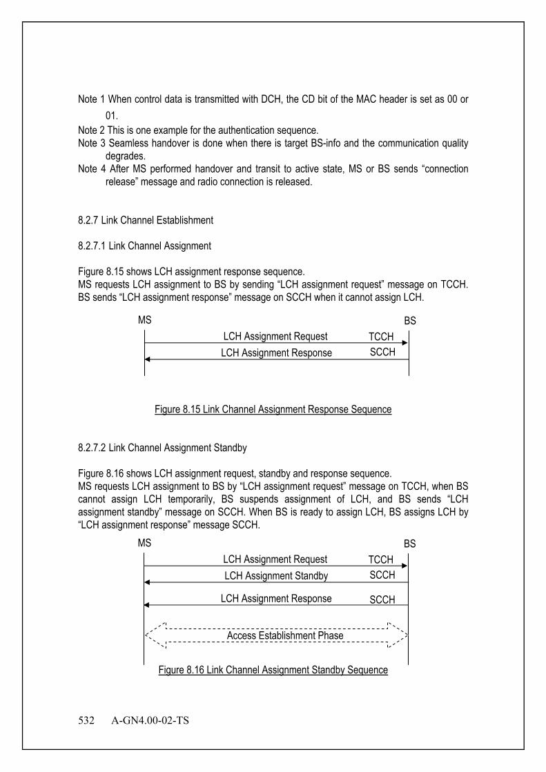
532 A-GN4.00-02-TS
Note 1 When control data is transmitted with DCH, the CD bit of the MAC header is set as 00 or 01.
Note 2 This is one example for the authentication sequence. Note 3 Seamless handover is done when there is target BS-info and the communication quality
degrades. Note 4 After MS performed handover and transit to active state, MS or BS sends “connection
release” message and radio connection is released. 8.2.7 Link Channel Establishment 8.2.7.1 Link Channel Assignment Figure 8.15 shows LCH assignment response sequence. MS requests LCH assignment to BS by sending “LCH assignment request” message on TCCH. BS sends “LCH assignment response” message on SCCH when it cannot assign LCH.
Figure 8.15 Link Channel Assignment Response Sequence
8.2.7.2 Link Channel Assignment Standby Figure 8.16 shows LCH assignment request, standby and response sequence. MS requests LCH assignment to BS by “LCH assignment request” message on TCCH, when BS cannot assign LCH temporarily, BS suspends assignment of LCH, and BS sends “LCH assignment standby” message on SCCH. When BS is ready to assign LCH, BS assigns LCH by “LCH assignment response” message SCCH.
Figure 8.16 Link Channel Assignment Standby Sequence
MS BS
LCH Assignment Standby SCCH
LCH Assignment Response SCCH
LCH Assignment Request TCCH
Access Establishment Phase
MS BS
LCH Assignment Response SCCH LCH Assignment Request TCCH

A-GN4.00-02-TS 533
8.2.7.3 Link Channel Re-request Sequence Figure 8.17 shows LCH assignment re-request sequence. MS requests LCH assignment to BS by sending “LCH assignment request” message on TCCH. After BS assigns LCH by sending “LCH assignment response” message, MS sends “LCH assignment re-request” message when it requests the assigned LCH to change to another LCH (e.g.: DL carrier sensing NG, etc). Then, BS assigns another LCH by sending “LCH assignment response” message.
Figure 8.17 Link Channel Assignment Re-request Sequence
8.2.7.4 Link Channel Request Standby and Link Channel Assignment Re-request Figure 8.18 shows LCH request standby and LCH assignment re-request sequence. MS requests LCH assignment to BS by sending “LCH assignment request” message on TCCH. BS suspends assignment of LCH when it cannot assign LCH temporarily and sends “LCH assignment standby” message on SCCH. BS assigns LCH by “LCH assignment response” message on SCCH when it is ready to assign LCH. When MS requests assigned LCH to change to other LCH (e.g.: DL carrier sensing NG, etc), MS sends “LCH assignment re-request” message. BS will then assign another LCH by sending “LCH assignment response” message.
MS BS LCH Assignment Request
TCCH SCCH LCH Assignment Response
SCCH
Access Establishment Phase
LCH Assignment Re-request SCCH LCH Assignment Response
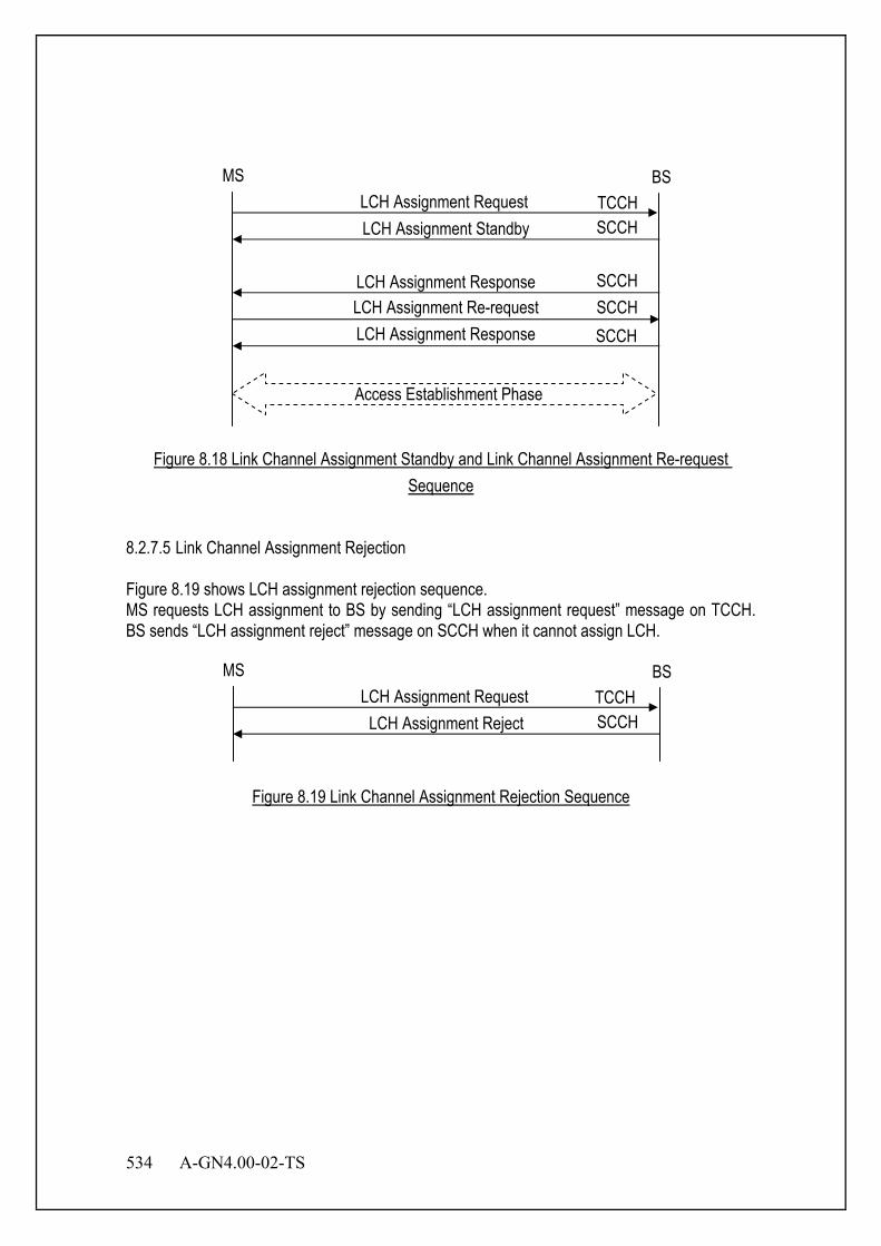
534 A-GN4.00-02-TS
Figure 8.18 Link Channel Assignment Standby and Link Channel Assignment Re-request Sequence
8.2.7.5 Link Channel Assignment Rejection Figure 8.19 shows LCH assignment rejection sequence. MS requests LCH assignment to BS by sending “LCH assignment request” message on TCCH. BS sends “LCH assignment reject” message on SCCH when it cannot assign LCH.
Figure 8.19 Link Channel Assignment Rejection Sequence
MS BS
LCH Assignment Reject SCCH LCH Assignment Request TCCH
MS BS
LCH Assignment Standby SCCH
LCH Assignment Response SCCH
LCH Assignment Request TCCH
Access Establishment Phase
SCCH LCH Assignment Re-request SCCH LCH Assignment Response
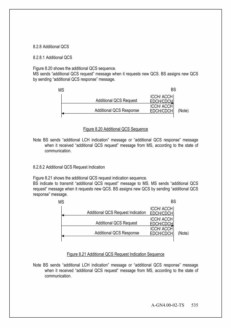
A-GN4.00-02-TS 535
8.2.8 Additional QCS 8.2.8.1 Additional QCS Figure 8.20 shows the additional QCS sequence. MS sends “additional QCS request” message when it requests new QCS. BS assigns new QCS by sending “additional QCS response” message.
Figure 8.20 Additional QCS Sequence
Note BS sends “additional LCH indication” message or “additional QCS response” message when it received “additional QCS request” message from MS, according to the state of communication.
8.2.8.2 Additional QCS Request Indication Figure 8.21 shows the additional QCS request indication sequence. BS indicate to transmit “additional QCS request” message to MS. MS sends “additional QCS request” message when it requests new QCS. BS assigns new QCS by sending “additional QCS response” message.
Figure 8.21 Additional QCS Request Indication Sequence
Note BS sends “additional LCH indication” message or “additional QCS response” message when it received “additional QCS request” message from MS, according to the state of communication.
MS BS
Additional QCS Response
Additional QCS Request ICCH/ ACCH EDCH/CDCH ICCH/ ACCH EDCH/CDCH (Note)
MS BS
Additional QCS Response
Additional QCS Request ICCH/ ACCH EDCH/CDCH ICCH/ ACCH EDCH/CDCH (Note)
Additional QCS Request Indication ICCH/ ACCH EDCH/CDCH
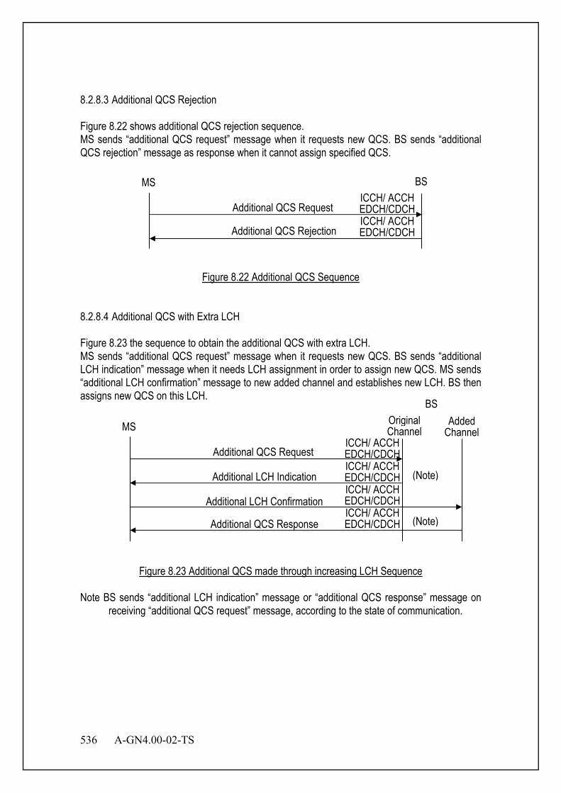
536 A-GN4.00-02-TS
8.2.8.3 Additional QCS Rejection Figure 8.22 shows additional QCS rejection sequence. MS sends “additional QCS request” message when it requests new QCS. BS sends “additional QCS rejection” message as response when it cannot assign specified QCS.
Figure 8.22 Additional QCS Sequence
8.2.8.4 Additional QCS with Extra LCH Figure 8.23 the sequence to obtain the additional QCS with extra LCH. MS sends “additional QCS request” message when it requests new QCS. BS sends “additional LCH indication” message when it needs LCH assignment in order to assign new QCS. MS sends “additional LCH confirmation” message to new added channel and establishes new LCH. BS then assigns new QCS on this LCH.
Figure 8.23 Additional QCS made through increasing LCH Sequence
Note BS sends “additional LCH indication” message or “additional QCS response” message on receiving “additional QCS request” message, according to the state of communication.
MS
BS
Additional QCS Request
Additional LCH Indication
Added Channel
Additional LCH Confirmation
Additional QCS Response
ICCH/ ACCH EDCH/CDCH ICCH/ ACCH EDCH/CDCH ICCH/ ACCH EDCH/CDCH ICCH/ ACCH EDCH/CDCH
Original Channel
(Note)
(Note)
MS BS
Additional QCS Rejection
Additional QCS Request ICCH/ ACCH EDCH/CDCH ICCH/ ACCH EDCH/CDCH
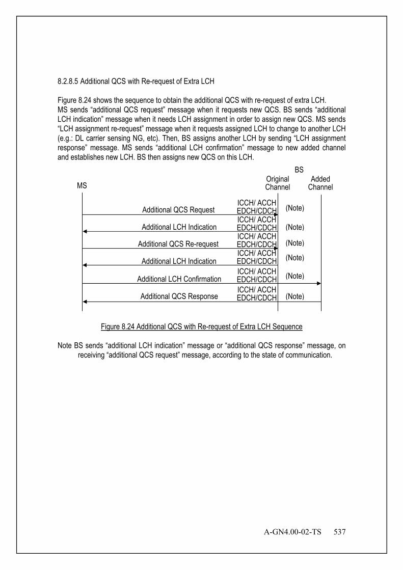
A-GN4.00-02-TS 537
8.2.8.5 Additional QCS with Re-request of Extra LCH Figure 8.24 shows the sequence to obtain the additional QCS with re-request of extra LCH. MS sends “additional QCS request” message when it requests new QCS. BS sends “additional LCH indication” message when it needs LCH assignment in order to assign new QCS. MS sends “LCH assignment re-request” message when it requests assigned LCH to change to another LCH (e.g.: DL carrier sensing NG, etc). Then, BS assigns another LCH by sending “LCH assignment response” message. MS sends “additional LCH confirmation” message to new added channel and establishes new LCH. BS then assigns new QCS on this LCH.
Figure 8.24 Additional QCS with Re-request of Extra LCH Sequence
Note BS sends “additional LCH indication” message or “additional QCS response” message, on receiving “additional QCS request” message, according to the state of communication.
MS
BS
Additional QCS Request
Additional LCH Indication
Added Channel
Additional LCH Confirmation
Additional QCS Response
(Note)
Additional LCH Indication
Additional QCS Re-request
ICCH/ ACCH EDCH/CDCH ICCH/ ACCH EDCH/CDCH ICCH/ ACCH EDCH/CDCH ICCH/ ACCH EDCH/CDCH
Original Channel
ICCH/ ACCH EDCH/CDCH ICCH/ ACCH EDCH/CDCH
(Note)
(Note)
(Note)
(Note)
(Note)
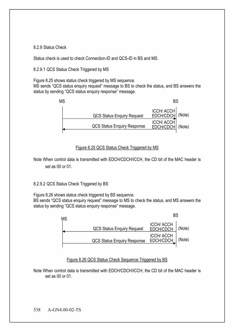
538 A-GN4.00-02-TS
8.2.9 Status Check Status check is used to check Connection-ID and QCS-ID in BS and MS. 8.2.9.1 QCS Status Check Triggered by MS Figure 8.25 shows status check triggered by MS sequence. MS sends “QCS status enquiry request” message to BS to check the status, and BS answers the status by sending “QCS status enquiry response” message.
Figure 8.25 QCS Status Check Triggered by MS
Note When control data is transmitted with EDCH/CDCH/ICCH, the CD bit of the MAC header is set as 00 or 01.
8.2.9.2 QCS Status Check Triggered by BS Figure 8.26 shows status check triggered by BS sequence. BS sends “QCS status enquiry request” message to MS to check the status, and MS answers the status by sending “QCS status enquiry response” message.
Figure 8.26 QCS Status Check Sequence Triggered by BS
Note When control data is transmitted with EDCH/CDCH/ICCH, the CD bit of the MAC header is set as 00 or 01.
MS BS
QCS Status Enquiry Request
QCS Status Enquiry Response
(Note) ICCH/ ACCH EDCH/CDCH ICCH/ ACCH EDCH/CDCH (Note)
MS BS
QCS Status Enquiry Request
QCS Status Enquiry Response
(Note) ICCH/ ACCH EDCH/CDCH ICCH/ ACCH EDCH/CDCH (Note)
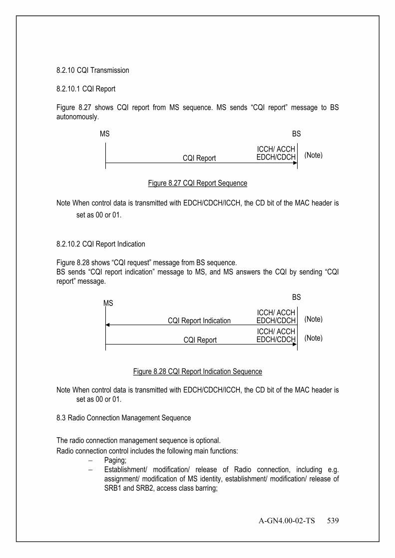
A-GN4.00-02-TS 539
8.2.10 CQI Transmission 8.2.10.1 CQI Report Figure 8.27 shows CQI report from MS sequence. MS sends “CQI report” message to BS autonomously.
Figure 8.27 CQI Report Sequence
Note When control data is transmitted with EDCH/CDCH/ICCH, the CD bit of the MAC header is set as 00 or 01.
8.2.10.2 CQI Report Indication Figure 8.28 shows “CQI request” message from BS sequence. BS sends “CQI report indication” message to MS, and MS answers the CQI by sending “CQI report” message.
Figure 8.28 CQI Report Indication Sequence
Note When control data is transmitted with EDCH/CDCH/ICCH, the CD bit of the MAC header is set as 00 or 01.
8.3 Radio Connection Management Sequence The radio connection management sequence is optional. Radio connection control includes the following main functions:
− Paging; − Establishment/ modification/ release of Radio connection, including e.g.
assignment/ modification of MS identity, establishment/ modification/ release of SRB1 and SRB2, access class barring;
MS BS
CQI Report (Note) ICCH/ ACCH EDCH/CDCH
MS BS
CQI Report Indication
CQI Report
(Note) ICCH/ ACCH EDCH/CDCH ICCH/ ACCH EDCH/CDCH (Note)
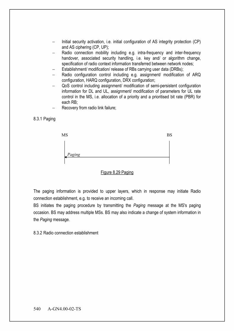
540 A-GN4.00-02-TS
− Initial security activation, i.e. initial configuration of AS integrity protection (CP) and AS ciphering (CP, UP);
− Radio connection mobility including e.g. intra-frequency and inter-frequency handover, associated security handling, i.e. key and/ or algorithm change, specification of radio context information transferred between network nodes;
− Establishment/ modification/ release of RBs carrying user data (DRBs); − Radio configuration control including e.g. assignment/ modification of ARQ
configuration, HARQ configuration, DRX configuration; − QoS control including assignment/ modification of semi-persistent configuration
information for DL and UL, assignment/ modification of parameters for UL rate control in the MS, i.e. allocation of a priority and a prioritised bit rate (PBR) for each RB;
− Recovery from radio link failure; 8.3.1 Paging
Paging
MS BS
Figure 8.29 Paging
The paging information is provided to upper layers, which in response may initiate Radio connection establishment, e.g. to receive an incoming call. BS initiates the paging procedure by transmitting the Paging message at the MS's paging occasion. BS may address multiple MSs. BS may also indicate a change of system information in the Paging message. 8.3.2 Radio connection establishment

A-GN4.00-02-TS 541
Radio ConnectionSetup
Radio ConnectionRequest
MS BS
Radio ConnectionSetupComplete
Figure 8.30 Radio connection establishment
The purpose of this procedure is to establish an Radio connection. Radio connection establishment involves SRB1 establishment. Upon initiation of the procedure, the MS shall check ACB:
− SIBB1 provides cellBarred indicator; no timer. Used before camp. − SIbb2 provides OriginatingCalls / EmergencyCalls and OriginatingSignalling ’s
ACB. − mobile terminating access is always allowed except for T302 running. − if access to cell is barred, MS shall inform upper layers about the failure to
establish the Radio connection and that access barring is applicable − if barring alleviation, MS shall inform upper layers about it.
The Radio connection Request message includes a MS Identity, establishment Cause for BS to identify whether it is emergency connection and the priority of the requested connection. The Radio connection Setup message includes the dedicated radio resource configuration for the radio connection, which may includes the radio bearer ids and corresponding configurations to be added and released,and the configuration for MAC layer. 8.3.2.1 Radio connectionSetupComplete The Radio connectionSetupComplete message includes possible registered core network information, etc.
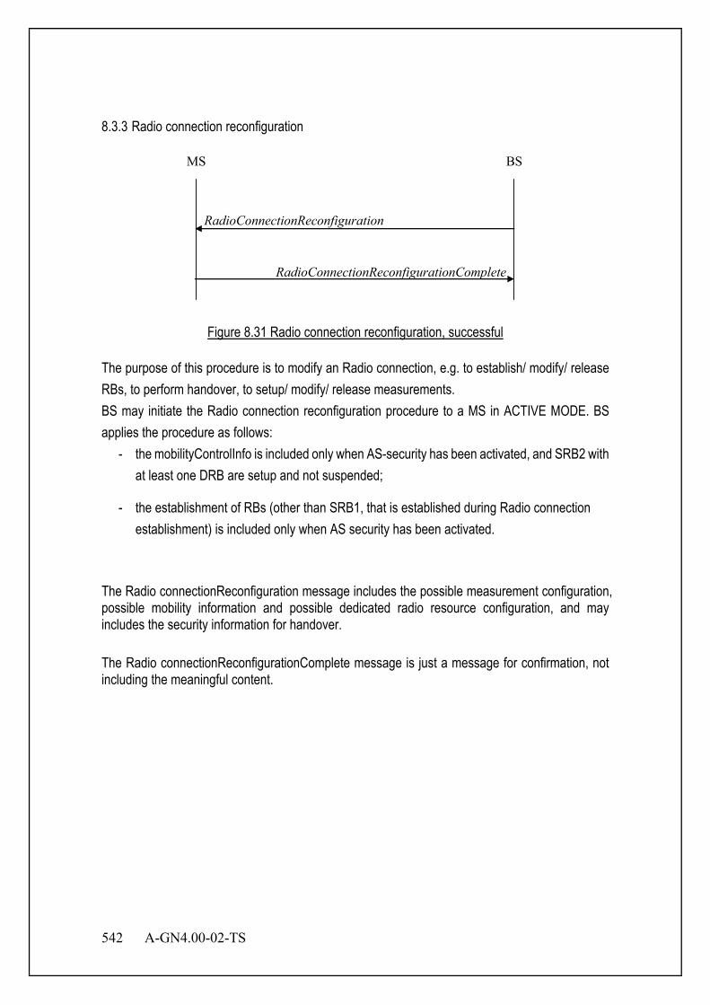
542 A-GN4.00-02-TS
8.3.3 Radio connection reconfiguration
RadioConnectionReconfigurationComplete
RadioConnectionReconfiguration
MS BS
Figure 8.31 Radio connection reconfiguration, successful
The purpose of this procedure is to modify an Radio connection, e.g. to establish/ modify/ release RBs, to perform handover, to setup/ modify/ release measurements. BS may initiate the Radio connection reconfiguration procedure to a MS in ACTIVE MODE. BS applies the procedure as follows:
- the mobilityControlInfo is included only when AS-security has been activated, and SRB2 with at least one DRB are setup and not suspended;
- the establishment of RBs (other than SRB1, that is established during Radio connection establishment) is included only when AS security has been activated.
The Radio connectionReconfiguration message includes the possible measurement configuration, possible mobility information and possible dedicated radio resource configuration, and may includes the security information for handover. The Radio connectionReconfigurationComplete message is just a message for confirmation, not including the meaningful content.
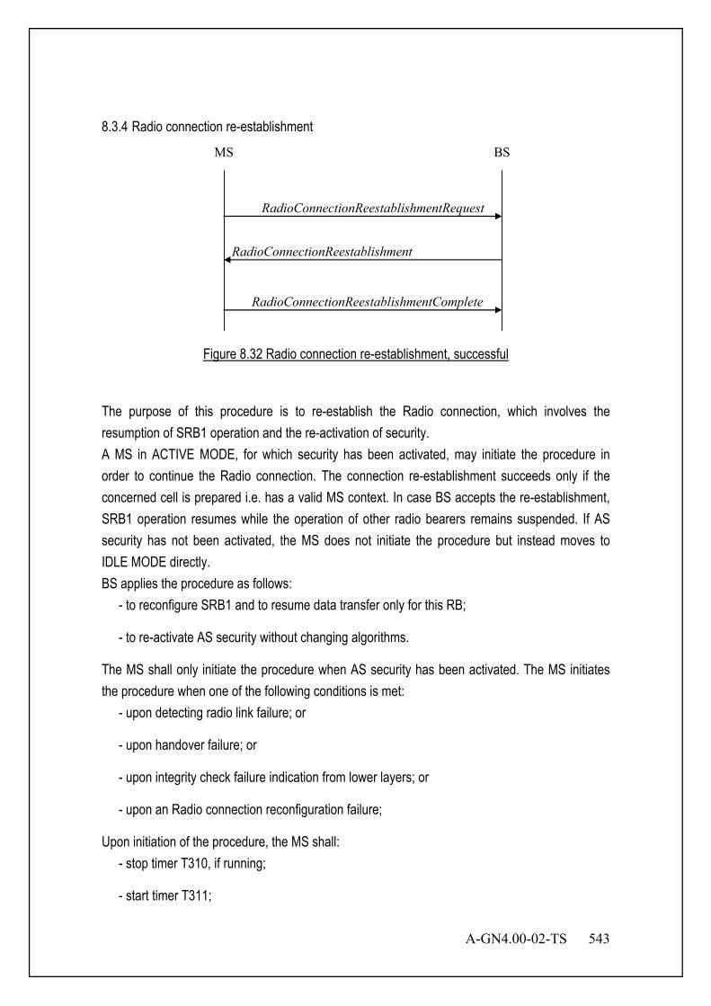
A-GN4.00-02-TS 543
8.3.4 Radio connection re-establishment
RadioConnectionReestablishmentRequest
MS BS
RadioConnectionReestablishment
RadioConnectionReestablishmentComplete
Figure 8.32 Radio connection re-establishment, successful
The purpose of this procedure is to re-establish the Radio connection, which involves the resumption of SRB1 operation and the re-activation of security. A MS in ACTIVE MODE, for which security has been activated, may initiate the procedure in order to continue the Radio connection. The connection re-establishment succeeds only if the concerned cell is prepared i.e. has a valid MS context. In case BS accepts the re-establishment, SRB1 operation resumes while the operation of other radio bearers remains suspended. If AS security has not been activated, the MS does not initiate the procedure but instead moves to IDLE MODE directly. BS applies the procedure as follows:
- to reconfigure SRB1 and to resume data transfer only for this RB;
- to re-activate AS security without changing algorithms.
The MS shall only initiate the procedure when AS security has been activated. The MS initiates the procedure when one of the following conditions is met:
- upon detecting radio link failure; or
- upon handover failure; or
- upon integrity check failure indication from lower layers; or
- upon an Radio connection reconfiguration failure;
Upon initiation of the procedure, the MS shall: - stop timer T310, if running;
- start timer T311;
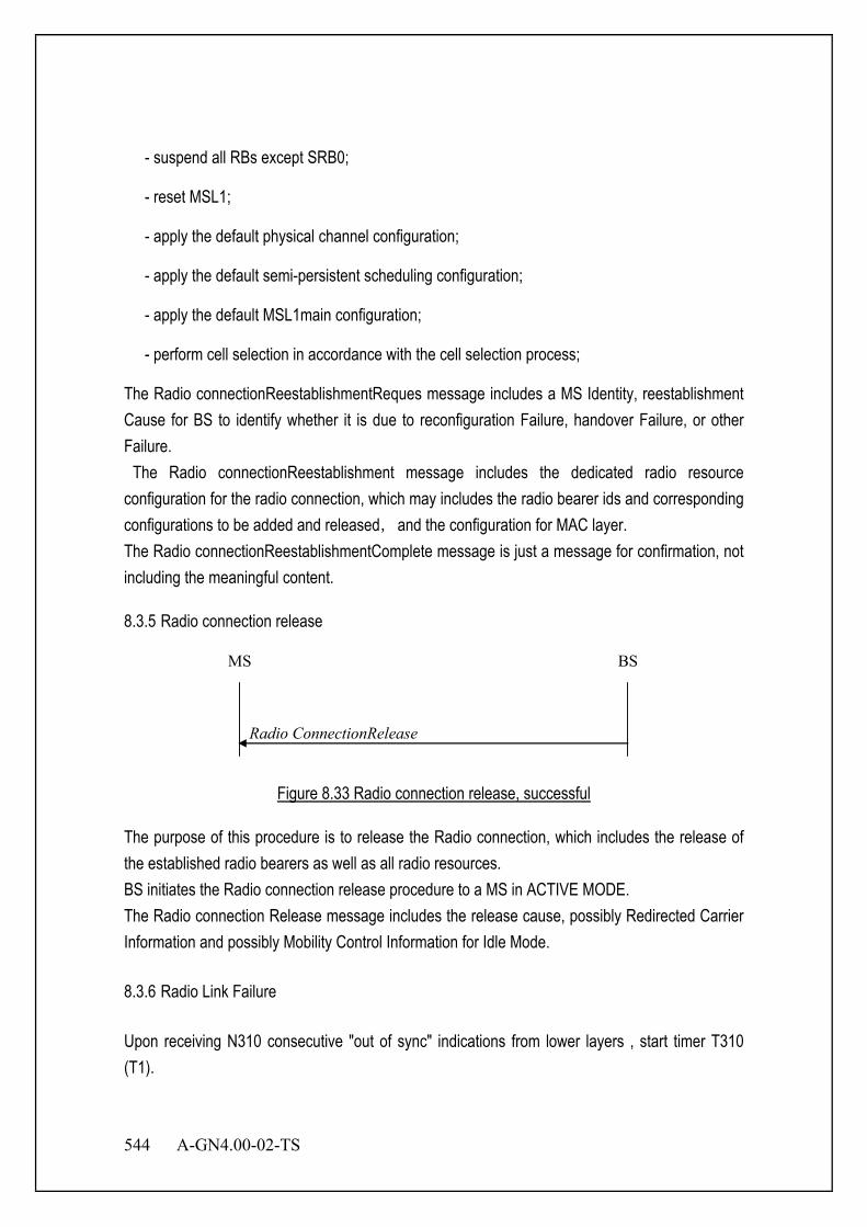
544 A-GN4.00-02-TS
- suspend all RBs except SRB0;
- reset MSL1;
- apply the default physical channel configuration;
- apply the default semi-persistent scheduling configuration;
- apply the default MSL1main configuration;
- perform cell selection in accordance with the cell selection process;
The Radio connectionReestablishmentReques message includes a MS Identity, reestablishment Cause for BS to identify whether it is due to reconfiguration Failure, handover Failure, or other Failure. The Radio connectionReestablishment message includes the dedicated radio resource configuration for the radio connection, which may includes the radio bearer ids and corresponding configurations to be added and released,and the configuration for MAC layer. The Radio connectionReestablishmentComplete message is just a message for confirmation, not including the meaningful content. 8.3.5 Radio connection release
Radio ConnectionRelease
MS BS
Figure 8.33 Radio connection release, successful
The purpose of this procedure is to release the Radio connection, which includes the release of the established radio bearers as well as all radio resources. BS initiates the Radio connection release procedure to a MS in ACTIVE MODE. The Radio connection Release message includes the release cause, possibly Redirected Carrier Information and possibly Mobility Control Information for Idle Mode. 8.3.6 Radio Link Failure Upon receiving N310 consecutive "out of sync" indications from lower layers , start timer T310 (T1).

A-GN4.00-02-TS 545
upon T310 expiry, consider radio link failure to be detected. If AS security has not been activated, start T311(T2) and initiate the connection re-establishment procedure . Upon T311 expiry, the MS shall perform the actions upon leaving ACTIVE MODE. 8.4 Optional Mobility sequence Measurements to be performed by a MS for mobility are classified:
- Intra-frequency BS measurements; - Inter-frequency BS measurements;
For each measurement type one or several measurement objects can be defined (a measurement object defines e.g. the carrier frequency to be monitored). For each measurement object one or several reporting configurations can be defined (a reporting configuration defines the reporting criteria). Three reporting criteria are used: event triggered reporting, periodic reporting and event triggered periodic reporting. The association between a measurement object and a reporting configuration is created by a measurement identity. By using several measurement identities (one for each measurement object, reporting configuration pair) it is possible:
- To associate several reporting configurations to one measurement object and; - To associate one reporting configuration to several measurement objects.
The measurements identity is as well used when reporting results of the measurements. Measurement commands are used by BS to order the MS to start measurements, modify measurements or stop measurements. In BS ACTIVE MODE state, network-controlled MS-assisted handovers are performed and various DRX cycles are supported. In BS IDLE MODE state, cell reselections are performed and DRX is supported. 8.4.1 Mobility Management in IDLE State 8.4.1.1 Cell selection - The MS may search each carrier in turn (“initial cell selection”) or make use of stored
information to shorten the search (“stored information cell selection”). - The MS seeks to identify a suitable cell; if it is not able to identify a suitable cell it seeks to
identify an acceptable cell. When a suitable cell is found or if only an acceptable cell is found it camps on that cell and commence the cell reselection procedure:
- An acceptable cell is one for which the measured cell attributes satisfy the cell selection criteria

546 A-GN4.00-02-TS
and the cell is not barred;
Transition to IDLE MODE: - On transition from ACTIVE MODE to IDLE MODE, a MS should camp on the last cell for which
it was in ACTIVE MODE or a cell/any cell of set of cells or frequency be assigned by radio connection aignalling in the state transition message.
Recovery from out of coverage: - The MS should attempt to find a suitable cell in the manner described for stored information or
initial cell selection above. If no suitable cell is found on any frequency or RAT the MS should attempt to find an acceptable cell.
8.4.1.2 Cell reselection MS in IDLE MODE performs cell reselection. The principles of the procedure are the following: - The MS makes measurements of attributes of the serving and neighbour cells to enable the
reselection process: - There is no need to indicate neighbouring cell in the serving cell system information to enable
the MS to search and measure a cell i.e. BS relies on the MS to detect the neighbouring cells; - For the search and measurement of inter-frequency neighbouring cells, only the carrier
frequencies need to be indicated; - Measurements may be omitted if the serving cell attribute fulfils particular search or
measurement criteria. - Cell reselection identifies the cell that the MS should camp on. It is based on cell reselection
criteria which involves measurements of the serving and neighbour cells: - Intra-frequency reselection is based on ranking of cells; - For inter-frequency neighbouring cells, it is possible to indicate layer-specific cell reselection
parameters (e.g., layer specific offset). These parameters are common to all neighbouring cells on a frequency;
- An NCL can be provided by the serving cell to handle specific cases for intra- and inter-frequency neighbouring cells. This NCL contains cell specific cell reselection parameters (e.g., cell specific offset) for specific neighbouring cells;
- Black lists can be provided to prevent the MS from reselecting to specific intra- and inter-frequency neighbouring cells;
- Cell reselection can be speed dependent; - Cell reselection parameters are applicable for all MSs in a cell, but it is possible to configure

A-GN4.00-02-TS 547
specific reselection parameters per MS group or per MS. - Cell access restrictions, which consist of access class (AC) barring and cell reservation (e.g. for
cells "reserved for operator use") applicable for mobiles in idle state. 8.4.2 Mobility Management in active state 8.4.2.1 General The Mobility Support for MSs in active state handles all necessary steps for relocation/handover procedures, like processes that precede the final HO decision on the source network side (control and evaluation of MS and BS measurements taking into account certain MS specific area restrictions), preparation of resources on the target network side, commanding the MS to the new radio resources and finally releasing resources on the (old) source network side. It contains mechanisms to transfer context data between BSs, and to update node relations on C-plane and U-plane.
In active state, BS-controlled MS-assisted handovers are performed and various DRX cycles are supported:
The MS makes measurements of attributes of the serving and neighbour cells to enable the process: - There is no need to indicate neighbouring cell to enable the MS to search and measure a cell
i.e. BS relies on the MS to detect the neighbouring cells; - For the search and measurement of inter-frequency neighbouring cells, at least the carrier
frequencies need to be indicated; - Network signals reporting criteria for event-triggered and periodical reporting; - An NCL can be provided by the serving cell by radio connection dedicated signalling to handle
specific cases for intra- and inter-frequency neighbouring cells. This NCL contains cell specific measurement parameters (e.g. cell specific offset) for specific neighbouring cells;
- Black lists can be provided to prevent the MS from measuring specific neighbouring cells. Depending on whether the MS needs transmission/reception gaps to perform the relevant measurements, measurements are classified as gap assisted or non-gap assisted. A non-gap assisted measurement is a measurement on a cell that does not require transmission/reception gaps to allow the measurement to be performed. A gap assisted measurement is a measurement on a cell that does require transmission/reception gaps to allow the measurement to be performed. Gap patterns (as opposed to individual gaps) are configured and activated by radio connection.
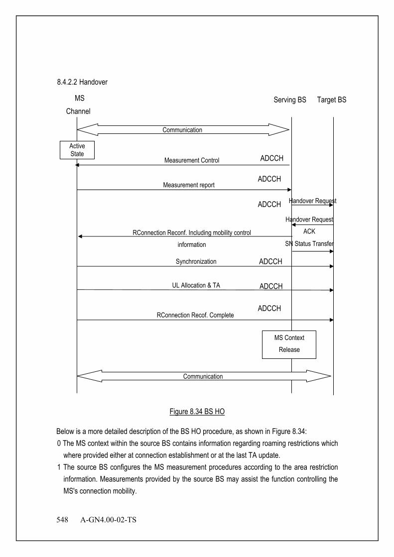
548 A-GN4.00-02-TS
8.4.2.2 Handover
Figure 8.34 BS HO
Below is a more detailed description of the BS HO procedure, as shown in Figure 8.34: 0 The MS context within the source BS contains information regarding roaming restrictions which
where provided either at connection establishment or at the last TA update. 1 The source BS configures the MS measurement procedures according to the area restriction
information. Measurements provided by the source BS may assist the function controlling the MS's connection mobility.
Target BS MS
RConnection Reconf. Including mobility control information
Measurement report
Handover Request
Handover Request ACK
Serving BS
SN Status Transfer
ADCCH Synchronization
UL Allocation & TA
RConnection Recof. Complete
ADCCH
Active State
Channel
MS Context Release
Communication
ADCCH
ADCCH
ADCCH
ADCCH
Measurement Control
Communication

A-GN4.00-02-TS 549
2 MS is triggered to send MEASUREMENT REPORT by the rules set by i.e. system information, specification etc.
3 Source BS makes decision based on MEASUREMENT REPORT and RRM information to hand off MS.
4 The source BS issues a HANDOVER REQUEST message to the target BS to prepare the HO at the target side.
5 Admission Control may be performed by the target BS dependent on the received E-RAB QoS information to increase the likelihood of a successful HO, if the resources can be granted by target BS.
6 Target BS prepares HO with L1/L2 and sends the HANDOVER REQUEST ACKNOWLEDGE to the source BS.
7 The target BS generates the radio connection message to perform the handover, i.e Radio connectionReconfiguration message including the mobilityControlInformation, to be sent by the source BS towards the MS. The source BS performs the necessary integrity protection and ciphering of the message.
8 The source BS sends the SN STATUS TRANSFER message to the target BS to convey the uplink MSL 3 SN receiver status and the downlink MSL 3 SN transmitter status for which MSL 3 status preservation applies. The uplink MSL 3 SN receiver status includes at least the MSL 3 SN of the first missing UL SDU and may include a bit map of the receive status of the out of sequence UL SDUs that the MS needs to retransmit in the target cell, if there are any such SDUs. The downlink MSL 3 SN transmitter status indicates the next MSL 3 SN that the target BS shall assign to new SDUs, not having a MSL 3 SN yet. The source BS may omit sending this message if none of the E-RABs of the MS shall be treated with MSL 3 status preservation.
9 After receiving the Radio connection Reconfiguration message including the mobilityControlInformation , MS performs synchronisation to target BS and accesses the target cell via ATCCH, following a contention-free procedure if a dedicated ATCCH access sequence was indicated in the mobilityControlInformation, or following a contention-based procedure if no dedicated access sequence was indicated. MS derives target BS specific keys and configures the selected security algorithms to be used in the target cell.
10 The target BS responds with UL allocation and timing advance. 11 When the MS has successfully accessed the target cell, the MS sends the
RadioconnectionReconfigurationComplete message (C-MSID) to confirm the handover, along with an uplink Buffer Status Report, whenever possible, to the target BS to indicate that the handover procedure is completed for the MS. The target BS verifies the C-MSID sent in the RadioconnectionReconfigurationComplete message. The target BS can now begin sending data to the MS.

550 A-GN4.00-02-TS
12 Upon reception of the MS CONTEXT RELEASE message, the source BS can release radio and C-plane related resources associated to the MS context. Any ongoing data forwarding may continue.
8.4.3 Measurements Measurements to be performed by a MS for intra/inter-frequency mobility can be controlled by BS, using broadcast or dedicated control. In IDLE MODE state, a MS shall follow the measurement parameters defined for cell reselection specified by the BS broadcast. The use of dedicated measurement control for IDLE MODE state is possible through the provision of MS specific priorities . In ACTIVE MODE state, a MS shall follow the measurement configurations specified by radio connection signalling directed from the BS. Intra-frequency neighbour (cell) measurements and inter-frequency neighbour (cell) measurements are defined as follows: - Intra-frequency neighbour (cell) measurements: Neighbour cell measurements performed by the
MS are intra-frequency measurements when the current and target cell operates on the same carrier frequency. The MS shall be able to carry out such measurements without measurement gaps.
- Inter-frequency neighbour (cell) measurements: Neighbour cell measurements performed by the MS are inter-frequency measurements when the neighbour cell operates on a different carrier frequency, compared to the current cell. The MS should not be assumed to be able to carry out such measurements without measurement gaps.
- Whether a measurement is non gap assisted or gap assisted depends on the MS's capability and current operating frequency. The MS determines whether a particular cell measurement needs to be performed in a transmission/reception gap and the scheduler needs to know whether gaps are needed:
- Same carrier frequency and cell bandwidths (Scenario A): an intra-frequency scenario; not measurement gap assisted.
- Same carrier frequency, bandwidth of the target cell smaller than the bandwidth of the current cell (Scenario B): an intra-frequency scenario; not measurement gap assisted.
- Same carrier frequency, bandwidth of the target cell larger than the bandwidth of the current cell (Scenario C): an intra-frequency scenario; not measurement gap assisted.
- Different carrier frequencies, bandwidth of the target cell smaller than the bandwidth of the current cell and bandwidth of the target cell within bandwidth of the current cell (Scenario D): an inter-frequency scenario; measurement gap-assisted scenario.
- Different carrier frequencies, bandwidth of the target cell larger than the bandwidth of the
A-GN4.00-02-TS 551
current cell and bandwidth of the current cell within bandwidth of the target cell (Scenario E): an inter-frequency scenario; measurement gap-assisted scenario.
- Different carrier frequencies and non-overlapping bandwidth, (Scenario F): an inter-frequency scenario; measurement gap-assisted scenario.
- Measurement gaps patterns are configured and activated by Radio connection signalling. 8.4.3.1 Intra-frequency neighbour (cell) measurements In a system with frequency reuse = 1, mobility within the same frequency layer (i.e. between cells with the same carrier frequency) is predominant. Good neighbour cell measurements are needed for cells that have the same carrier frequency as the serving cell in order to ensure good mobility support and easy network deployment. Search for neighbour cells with the same carrier frequency as the serving cell, and measurements of the relevant quantities for identified cells are needed. NOTE: To avoid MS activity outside the DRX cycle, the reporting criteria for neighbour cell measurements should match the used DRX cycle. 8.4.3.2 Inter-frequency neighbour (cell) measurements Regarding mobility between different frequency layers (i.e. between cells with a different carrier frequency), MS may need to perform neighbour cell measurements during DL/UL idle periods that are provided by DRX or packet scheduling. 8.4.3.3 measurement configuration The measurement configuration includes the following parameters:
1. Measurement objects: The objects on which the MS shall perform the measurements.
- For intra-frequency and inter-frequency measurements a measurement object is a single carrier frequency. Associated with this carrier frequency, BS can configure a list of cell specific offsets and a list of ‘blacklisted’ cells. Blacklisted cells are not considered in event evaluation or measurement reporting.
2. Reporting configurations: A list of reporting configurations where each reporting configuration consists of the following:
- Reporting criterion: The criterion that triggers the MS to send a measurement report. This can either be periodical or a single event description.
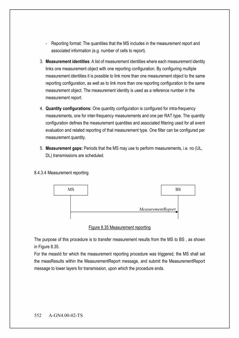
552 A-GN4.00-02-TS
- Reporting format: The quantities that the MS includes in the measurement report and associated information (e.g. number of cells to report).
3. Measurement identities: A list of measurement identities where each measurement identity links one measurement object with one reporting configuration. By configuring multiple measurement identities it is possible to link more than one measurement object to the same reporting configuration, as well as to link more than one reporting configuration to the same measurement object. The measurement identity is used as a reference number in the measurement report.
4. Quantity configurations: One quantity configuration is configured for intra-frequency measurements, one for inter-frequency measurements and one per RAT type. The quantity configuration defines the measurement quantities and associated filtering used for all event evaluation and related reporting of that measurement type. One filter can be configured per measurement quantity.
5. Measurement gaps: Periods that the MS may use to perform measurements, i.e. no (UL, DL) transmissions are scheduled.
8.4.3.4 Measurement reporting
MeasurementReport
MS BS
Figure 8.35 Measurement reporting
The purpose of this procedure is to transfer measurement results from the MS to BS , as shown in Figure 8.35. For the measId for which the measurement reporting procedure was triggered, the MS shall set the measResults within the MeasurementReport message, and submit the MeasurementReport message to lower layers for transmission, upon which the procedure ends.
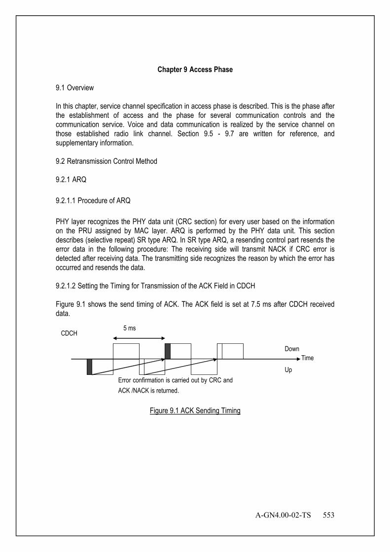
A-GN4.00-02-TS 553
Chapter 9 Access Phase 9.1 Overview In this chapter, service channel specification in access phase is described. This is the phase after the establishment of access and the phase for several communication controls and the communication service. Voice and data communication is realized by the service channel on those established radio link channel. Section 9.5 - 9.7 are written for reference, and supplementary information. 9.2 Retransmission Control Method 9.2.1 ARQ 9.2.1.1 Procedure of ARQ PHY layer recognizes the PHY data unit (CRC section) for every user based on the information on the PRU assigned by MAC layer. ARQ is performed by the PHY data unit. This section describes (selective repeat) SR type ARQ. In SR type ARQ, a resending control part resends the error data in the following procedure: The receiving side will transmit NACK if CRC error is detected after receiving data. The transmitting side recognizes the reason by which the error has occurred and resends the data. 9.2.1.2 Setting the Timing for Transmission of the ACK Field in CDCH
Figure 9.1 shows the send timing of ACK. The ACK field is set at 7.5 ms after CDCH received data.
CDCH
Time Down
Up
5 ms
Error confirmation is carried out by CRC and ACK /NACK is returned.
Figure 9.1 ACK Sending Timing

554 A-GN4.00-02-TS
9.2.1.3 Timing of Retransmission Figure 9.2 shows ARQ re-sending timing when the right of communication is continuously granted to MS. MS will transmit NACK of CDCH after 7.5 ms, if the data error of 2 is detected. BS recognizes an error on receiving NACK and, re-sends 2’ to MS on DL CDCH after 7.5 ms.
CDCH
Time Down
Up
5 ms
If a CRC error occurs, NACK will be transmitted after 7.5 ms and it will be resent after the 7.5 ms.
1
1’
4 3
3’
5 2 2
2’ 4’
Figure 9.2 ARQ Retransmission Timing
9.2.1.4 Example of ARQ Retransmission The example of resending an ARQ is introduced in this section. Figure 9.3 shows the example of resending in case that the same data serve as an error continuously. Data are re-sent to the specified retry count. Moreover, continuous data are transmitted except for resending. Figure 9.4 shows the example of resending in case that continuous different data serve as an error. Since resending control is carried out by the same time relation, even if data 2 and 3 are continuous data, they are resent independently.
CDCH
Time Down
Up
5 ms
2
A
3
N
4
A
2
A
5
N
6
A
2
A
7
A
(A : ACK N : NACK)
1
Figure 9.3 Example of ARQ Retransmission 1

A-GN4.00-02-TS 555
CDCH
Time Down
Up
5 ms
1 2
A
3
N
4
N
2
A
3
A
5
A
6
A
7
A
(A : ACK N : NACK )
Figure 9.4 Example of ARQ Retransmission 2
9.2.1.5 Example of Sequence Figure 9.5 shows the example of UL ARQ sequence.
MS BS
Uplink Data2
CRC ErrorUplink Data1
NACK
Uplink Data1(Retransmission)
ACK
Figure 9.5 Example of UL
556 A-GN4.00-02-TS
9.2.1.6 About the Switch of ARQ and the Adaptive Modulation This section describes the way to switch ARQ and adaptive modulation. Transmission side changes modulation class when the CRC error exceeds the defined limit of X times. Upper layer decides the limit of X according to QoS etc. 9.2.2 HARQ 9.2.2.1 Procedure of HARQ PHY Layer receives a set of PHY header and a set of PHY payload units on a TDMA frame, identifies the users for these data units according to the MAP information provided by the MAC and performs HARQ on the received PHY data units. Chase combining is described as follows as one method of HARQ. Figure 9.6 shows the block diagram of the HARQ receiver. HARQ procedure is described as follows: 1. FFT operation is performed on the received base band signal The user signal is detected by
FFT operation. 2. De-interleaving operation is performed and buffered on the detected user signal. No
maximum ratio combining is done for the first time. De-interleaving operation is only applied after retransmitted data for NACKs is received.
3. The buffer is released if no error is detected. The ACK field is set accordingly on the ANCH channel’s PHY Header. The transmission timing of this ANCH is explained in the next chapter.
4. The reception buffer will not be released if an error is detected. The buffered data will be kept in the buffer until the reception of the retransmitted data. [Retransmission timing of the retransmitted data will be explained later.]. The NACK is set for the erroneous data in the ACK field of the PHY header and transmitted on the ANCH channel. The timing of the ANCH channel transmission is the second TDMA frame after the current frame.
5. NACK will be transmitted to the transmitting side if an error is detected. When the retransmitted data is received, the FFT operation is performed on the received signal and then de-Interleaving operation is conducted to the detected user signal. The de-Interleaved data is combined with the buffered data. The Error correction is performed on the combined data and then error detection will be performed. The process from FFT operation to error detection will be done when HARQ condition is satisfied. The condition is described in Section 9.2.2.3.

A-GN4.00-02-TS 557
Second Demodulation
First Demodulation
(Error Correction) De-interleaving Maximal Ratio
Combining Error
Detection
Reception Buffer Pool
ACK (PHY Header)
Base Band Reception Signal
ACK or NACK Transmission
Figure 9.6 Reception of Block Diagram of HARQ
9.2.2.2 Retransmission Rule in FM-Mode When EXCHs are retransmitted in FM-mode, the retransmission is done with the following rule.
EXCHs in the same slot as the first transmission are used in HARQ retransmission. EXCHs with smaller logical PRU number are firstly used for HARQ retransmission
and remaining EXCHs are used for new data transmission. The number of EXCH used for retransmission does not change in HARQ
retransmission. When the original data size is one/two EXCHs, retransmission data size is also one/two EXCHs, respectively.
Figure 9.7 shows an example of retransmission control. PHY data unit size does not change and the data is transmitted first in a slot in HARQ retransmission. It also shows the relationship between logical PRU assignment and symbol mapping method. In the first transmission, Data 1 is transmitted by EDCH 1 which combined EXCH 1 and EXCH 2. Data 2 is transmitted by EDCH 2 which combined EXCH 3 and EXCH 4. Data 3 is transmitted by EDCH 3 which combined EXCH 5 and EXCH 6. And Data 4 is transmitted by EDCH 4 which consists of only EXCH 7. Data 2 and Data 4 are retransmitted when an error occurs in communication of EDCH 2 and EDCH 4. By the first and the second rule, Data 2 is retransmitted by EDCH 1 which combined EXCH 1 and EXCH 2. According to the first, the second and the third rule, Data 4 is retransmitted by EDCH 3 which consists of EXCH 5. EXCH 3, EXCH 4, EXCH 6, and EXCH 7 which are not used by retransmission will then combine each other to from EDCH 2 and EDCH 4. Data 5 and Data 6 which are ready for transmission for the first time, will be sent by EDCH 2 and EDCH 4.
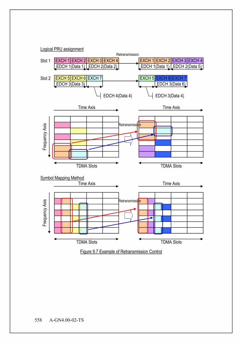
558 A-GN4.00-02-TS
Logical PRU assignment
Slot 1
Slot 2
Symbol Mapping MethodTime Axis
Freq
uenc
y Axis
TDMA Slots TDMA Slots
Time Axis
EXCH 1 EXCH 2 EXCH 3 EXCH 4 EXCH 1 EXCH 2 EXCH 3 EXCH 4EDCH 1(Data 1) EDCH 2(Data 2) EDCH 1(Data 1) EDCH 2(Data 5)
EXCH 6 EXCH 7EDCH 3(Data 3) EDCH 3(Data 6)EXCH 5 EXCH 6 EXCH 7 EXCH 5
Time Axis Time Axis
Freq
uenc
y Axis
TDMA Slots TDMA Slots
Retransmission
Retransmission
EDCH 4(Data 4) EDCH 3(Data 4)
Retransmission
Figure 9.7 Example of Retransmission Control

A-GN4.00-02-TS 559
9.2.2.3 HARQ Approval Condition It is necessary to assign enough number of PRU to retransmit PHY data unit. The same MCS and slot shall be used for the retransmission of the PHY data unit. If these conditions are not satisfied, HARQ information will be released. As an example, assume that ANCH, EXCH1, EXCH2, EXCH3 and EXCH4 are allocated for a user. When NACK is received for a particular MAC frame, and two EXCHs are required for retransmission, MAC will then request PHY layer to use the first two EXCHs given by the MAP field for the retransmission. When the NACK is received for multiple MAC frames simultaneously, the first MAC frame will be allocated to the first few available EXCHs which are indicated by MAP field. When the NACK is received for multiple MAC frames simultaneously, MAC will then try to allocate EXCHs for the transmission of all the MAC frames. MAC will allocate as many EXCHs as possible for frame transmission in case that sufficient EXCHs are not available. Remaining MAC frames will be retransmitted by MAC-ARQ in the future. 9.2.2.4 HARQ Cancel Condition HARQ cancel condition and the process are shown in Table 9.1. These conditions have a priority numbered from 1 to 5. If some conditions occurred at the same time, higher priority condition should be taken into use.
Table 9.1 Summary of HARQ Cancel Condition
No. Condition Outline of Process
1 Received ANCH is CRC error or ICCH format.
The HARQ retransmission data in the frame should be cleared, and notify the other side that ANCH is CRC error by HC=1.
2 Received ANCH is set HC=1. The HARQ retransmission data in the frame should be cleared
3 There is no PRU in the slot which has the HARQ retransmission data.
The HARQ retransmission data in the slot should be cleared.
4 There is the difference of MI between before and after retransmission.
The HARQ retransmission data in the MI applicable to slot should be cleared.
5 There are not enough number of PRU for HARQ retransmission data unit.
The PHY data unit which can not be retransmitted should be cleared.
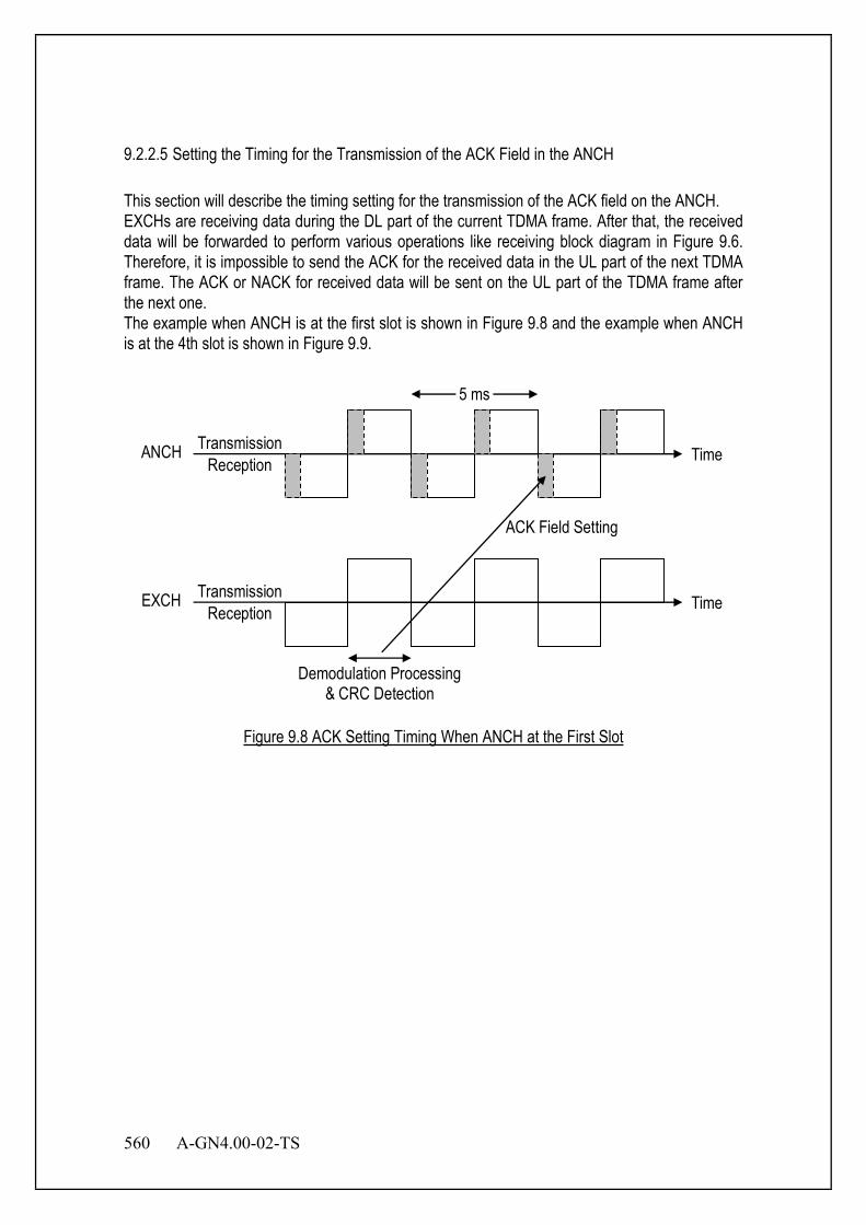
560 A-GN4.00-02-TS
9.2.2.5 Setting the Timing for the Transmission of the ACK Field in the ANCH This section will describe the timing setting for the transmission of the ACK field on the ANCH. EXCHs are receiving data during the DL part of the current TDMA frame. After that, the received data will be forwarded to perform various operations like receiving block diagram in Figure 9.6. Therefore, it is impossible to send the ACK for the received data in the UL part of the next TDMA frame. The ACK or NACK for received data will be sent on the UL part of the TDMA frame after the next one. The example when ANCH is at the first slot is shown in Figure 9.8 and the example when ANCH is at the 4th slot is shown in Figure 9.9.
Transmission Reception
EXCH Time
Transmission Reception
ANCH Time
5 ms
Demodulation Processing & CRC Detection
ACK Field Setting
Figure 9.8 ACK Setting Timing When ANCH at the First Slot

A-GN4.00-02-TS 561
Transmission Reception
EXCH Time
Transmission Reception
ANCH Time
5 ms
Demodulation Processing & CRC Detection
ACK Field Setting
Figure 9.9 ACK Setting Timing When ANCH at the Last Slot
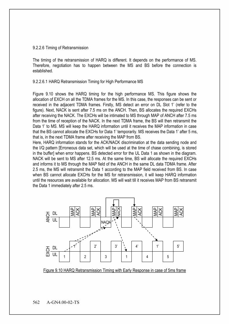
562 A-GN4.00-02-TS
9.2.2.6 Timing of Retransmission The timing of the retransmission of HARQ is different. It depends on the performance of MS. Therefore, negotiation has to happen between the MS and BS before the connection is established. 9.2.2.6.1 HARQ Retransmission Timing for High Performance MS Figure 9.10 shows the HARQ timing for the high performance MS. This figure shows the allocation of EXCH on all the TDMA frames for the MS. In this case, the responses can be sent or received in the adjacent TDMA frames. Firstly, MS detect an error on DL Slot 1’ (refer to the figure). Next, NACK is sent after 7.5 ms on the ANCH. Then, BS allocates the required EXCHs after receiving the NACK. The EXCHs will be intimated to MS through MAP of ANCH after 7.5 ms from the time of reception of the NACK. In the next TDMA frame, the BS will then retransmit the Data 1’ to MS. MS will keep the HARQ information until it receives the MAP information in case that the BS cannot allocate the EXCHs for Data 1’ temporarily. MS receives the Data 1’ after 5 ms, that is, in the next TDMA frame after receiving the MAP from BS. Here, HARQ information stands for the ACK/NACK discrimination at the data sending node and the I/Q pattern [Erroneous data set, which will be used at the time of chase combining, is stored in the buffer] when error happens. BS detected error for the UL Data 1 as shown in the diagram. NACK will be sent to MS after 12.5 ms. At the same time, BS will allocate the required EXCHs and informs it to MS through the MAP field of the ANCH in the same DL data TDMA frame. After 2.5 ms, the MS will retransmit the Data 1 according to the MAP field received from BS. In case when BS cannot allocate EXCHs for the MS for retransmission, it will keep HARQ information until the resources are available for allocation. MS will wait till it receives MAP from BS retransmit the Data 1 immediately after 2.5 ms.
NACK
MAP
ACK
MAP
ACK
MAP
NACK
1
1’
2
2’
MAP
ACK
3
3’
1
1’
4’
4 5
5’
MAP
ACK
MAP
ACK
DL UL AN
CH
DL UL EX
CH
Figure 9.10 HARQ Retransmission Timing with Early Response in case of 5ms frame
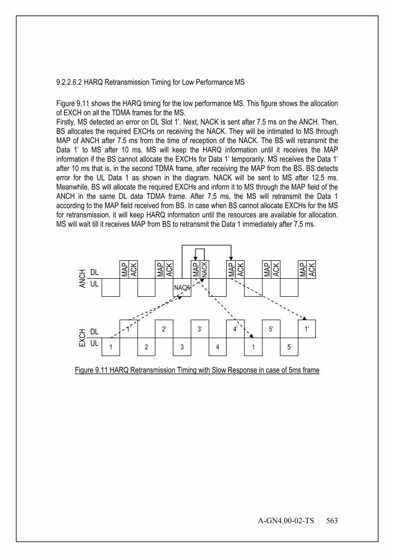
A-GN4.00-02-TS 563
9.2.2.6.2 HARQ Retransmission Timing for Low Performance MS Figure 9.11 shows the HARQ timing for the low performance MS. This figure shows the allocation of EXCH on all the TDMA frames for the MS. Firstly, MS detected an error on DL Slot 1’. Next, NACK is sent after 7.5 ms on the ANCH. Then, BS allocates the required EXCHs on receiving the NACK. They will be intimated to MS through MAP of ANCH after 7.5 ms from the time of reception of the NACK. The BS will retransmit the Data 1’ to MS after 10 ms. MS will keep the HARQ information until it receives the MAP information if the BS cannot allocate the EXCHs for Data 1’ temporarily. MS receives the Data 1’ after 10 ms that is, in the second TDMA frame, after receiving the MAP from the BS. BS detects error for the UL Data 1 as shown in the diagram. NACK will be sent to MS after 12.5 ms. Meanwhile, BS will allocate the required EXCHs and inform it to MS through the MAP field of the ANCH in the same DL data TDMA frame. After 7.5 ms, the MS will retransmit the Data 1 according to the MAP field received from BS. In case when BS cannot allocate EXCHs for the MS for retransmission, it will keep HARQ information until the resources are available for allocation. MS will wait till it receives MAP from BS to retransmit the Data 1 immediately after 7.5 ms.
4’
NACK
MAP
ACK
MAP
ACK
MAP
NACK
1
1’
2
2’
MAP
ACK
3
3’
1
1’
4 5
5’
MAP
ACK
MAP
ACK
DL UL AN
CH
DL UL EX
CH
Figure 9.11 HARQ Retransmission Timing with Slow Response in case of 5ms frame
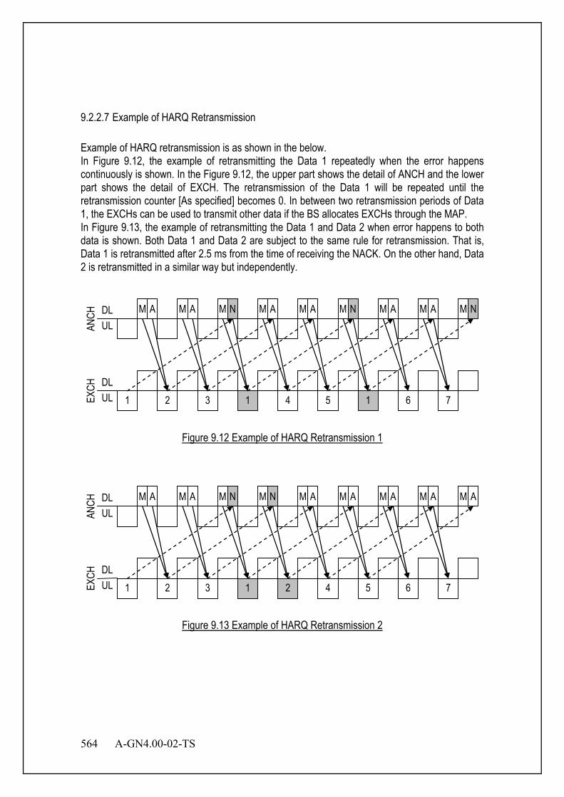
564 A-GN4.00-02-TS
9.2.2.7 Example of HARQ Retransmission Example of HARQ retransmission is as shown in the below. In Figure 9.12, the example of retransmitting the Data 1 repeatedly when the error happens continuously is shown. In the Figure 9.12, the upper part shows the detail of ANCH and the lower part shows the detail of EXCH. The retransmission of the Data 1 will be repeated until the retransmission counter [As specified] becomes 0. In between two retransmission periods of Data 1, the EXCHs can be used to transmit other data if the BS allocates EXCHs through the MAP. In Figure 9.13, the example of retransmitting the Data 1 and Data 2 when error happens to both data is shown. Both Data 1 and Data 2 are subject to the same rule for retransmission. That is, Data 1 is retransmitted after 2.5 ms from the time of receiving the NACK. On the other hand, Data 2 is retransmitted in a similar way but independently.
M A M N M A M A M N M A M A M N
1
2
3
1
4
5
1
6
M A
7
DL UL AN
CH
DL UL EX
CH
Figure 9.12 Example of HARQ Retransmission 1
M A M N M A M N M A M A M A M A
1
2
3
1
2
4
5
6
M A
7
DL UL AN
CH
DL UL EX
CH
Figure 9.13 Example of HARQ Retransmission 2
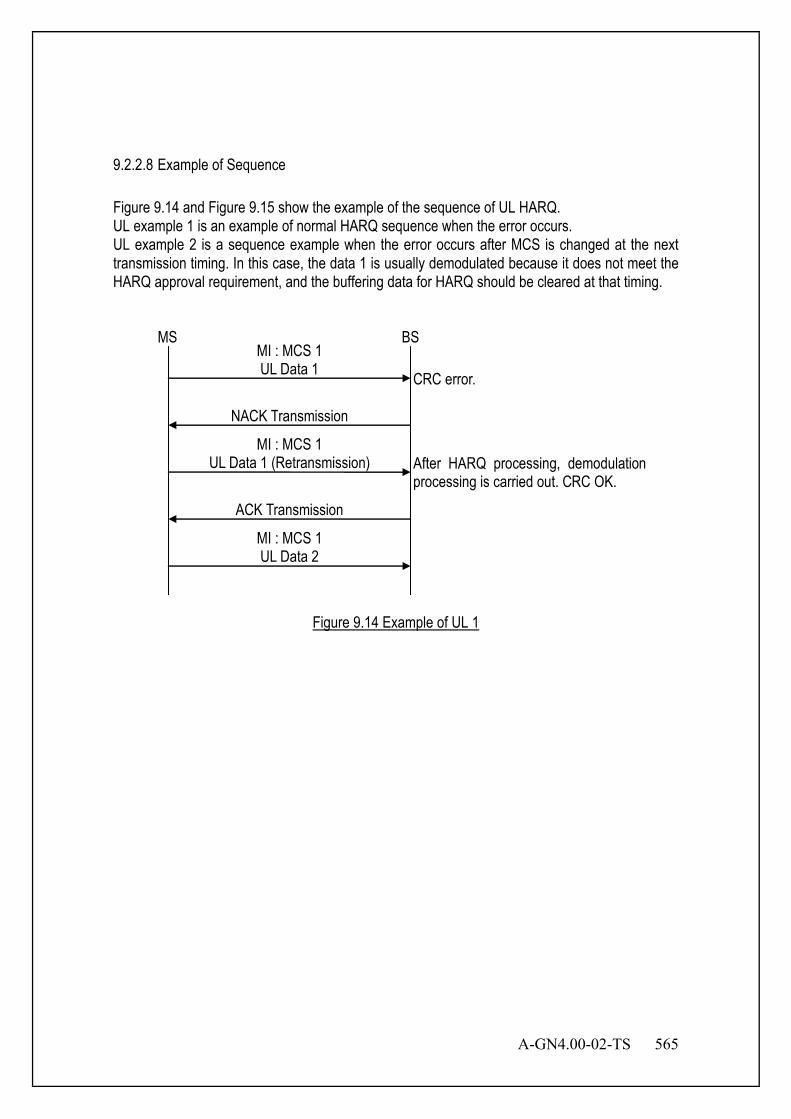
A-GN4.00-02-TS 565
9.2.2.8 Example of Sequence Figure 9.14 and Figure 9.15 show the example of the sequence of UL HARQ. UL example 1 is an example of normal HARQ sequence when the error occurs. UL example 2 is a sequence example when the error occurs after MCS is changed at the next transmission timing. In this case, the data 1 is usually demodulated because it does not meet the HARQ approval requirement, and the buffering data for HARQ should be cleared at that timing.
MS BS MI : MCS 1 UL Data 1
NACK Transmission
MI : MCS 1 UL Data 1 (Retransmission)
ACK Transmission
After HARQ processing, demodulationprocessing is carried out. CRC OK.
MI : MCS 1 UL Data 2
CRC error.
Figure 9.14 Example of UL 1
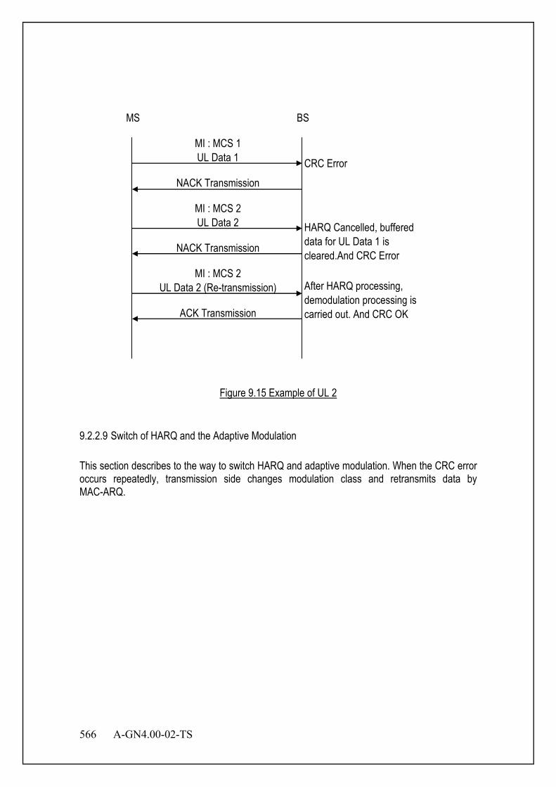
566 A-GN4.00-02-TS
MI : MCS 2UL Data 2 (Re-transmission)
NACK Transmission
MS BS
ACK Transmission
CRC Error
MI : MCS 2UL Data 2
NACK Transmission
HARQ Cancelled, buffereddata for UL Data 1 iscleared.And CRC Error
After HARQ processing,demodulation processing iscarried out. And CRC OK
MI : MCS 1UL Data 1
Figure 9.15 Example of UL 2
9.2.2.9 Switch of HARQ and the Adaptive Modulation This section describes to the way to switch HARQ and adaptive modulation. When the CRC error occurs repeatedly, transmission side changes modulation class and retransmits data by MAC-ARQ.
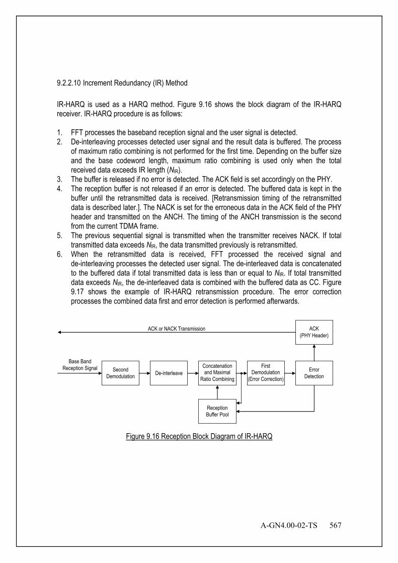
A-GN4.00-02-TS 567
9.2.2.10 Increment Redundancy (IR) Method IR-HARQ is used as a HARQ method. Figure 9.16 shows the block diagram of the IR-HARQ receiver. IR-HARQ procedure is as follows: 1. FFT processes the baseband reception signal and the user signal is detected. 2. De-interleaving processes detected user signal and the result data is buffered. The process
of maximum ratio combining is not performed for the first time. Depending on the buffer size and the base codeword length, maximum ratio combining is used only when the total received data exceeds IR length (NIR).
3. The buffer is released if no error is detected. The ACK field is set accordingly on the PHY. 4. The reception buffer is not released if an error is detected. The buffered data is kept in the
buffer until the retransmitted data is received. [Retransmission timing of the retransmitted data is described later.]. The NACK is set for the erroneous data in the ACK field of the PHY header and transmitted on the ANCH. The timing of the ANCH transmission is the second from the current TDMA frame.
5. The previous sequential signal is transmitted when the transmitter receives NACK. If total transmitted data exceeds NIR, the data transmitted previously is retransmitted.
6. When the retransmitted data is received, FFT processed the received signal and de-interleaving processes the detected user signal. The de-interleaved data is concatenated to the buffered data if total transmitted data is less than or equal to NIR. If total transmitted data exceeds NIR, the de-interleaved data is combined with the buffered data as CC. Figure 9.17 shows the example of IR-HARQ retransmission procedure. The error correction processes the combined data first and error detection is performed afterwards.
Second Demodulation
First Demodulation
(Error Correction) De-interleave
Concatenation and Maximal
Ratio Combining Error
Detection
Reception Buffer Pool
ACK (PHY Header)
Base Band Reception Signal
ACK or NACK Transmission
Figure 9.16 Reception Block Diagram of IR-HARQ

568 A-GN4.00-02-TS
Figure 9.17 IR-HARQ Retransmission Procedure
9.2.2.11 Retransmission Count HARQ retransmission time is separately specified. When the condition of HARQ retransmission is satisfied, the number of HARQ retransmission is counted. 9.3 Optional Retransmission Control Method 9.3.1 HARQ The HARQ within the MSL1 sublayer has the following characteristics:
- N-process Stop-And-Wait;
- HARQ transmits and retransmits transport blocks;
- In the downlink:
- Asynchronous adaptive HARQ;
- Uplink ACK/NAKs in response to downlink (re)transmissions are sent on AUANCH or AUEDCH;
Based Encoded Codeword LengthNIR
The First Transmission
Transmitted
Decoded
The Second Transmission
Decoded
Transmitted
The Third Transmission
Decoded
Transmitted
Combined
A-GN4.00-02-TS 569
- ADECCH signals the HARQ process number and if it is a transmission or retransmission;
- Retransmissions are always scheduled through ADECCH.
- In the uplink:
- Synchronous HARQ;
- Maximum number of retransmissions configured per MS (as opposed to per radio bearer);
- Downlink ACK/NAKs in response to uplink (re)transmissions are sent on ADHICH;
- HARQ operation in uplink is governed by the following principles (summarized in Table 9.1-1):
1) Regardless of the content of the HARQ feedback (ACK or NACK), when a ADECCH for the MS is correctly received, the MS follows what the ADECCH asks the MS to do i.e. perform a transmission or a retransmission (referred to as adaptive retransmission);
2) When no ADECCH addressed to the C-MSID of the MS is detected, the HARQ feedback dictates how the MS performs retransmissions:
- NACK: the MS performs a non-adaptive retransmission i.e. a retransmission on the same uplink resource as previously used by the same process;
- ACK: the MS does not perform any UL (re)transmission and keeps the data in the HARQ buffer. A ADECCH is then required to perform a retransmission i.e. a non-adaptive retransmission cannot follow.
- Measurement gaps are of higher priority than HARQ retransmissions: whenever an HARQ retransmission collides with a measurement gap, the HARQ retransmission does not take place.
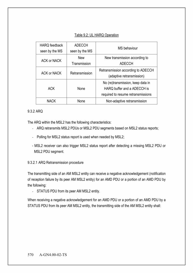
570 A-GN4.00-02-TS
Table 9.2: UL HARQ Operation
HARQ feedback seen by the MS
ADECCH seen by the MS
MS behaviour
ACK or NACK New
Transmission New transmission according to
ADECCH
ACK or NACK Retransmission Retransmission according to ADECCH
(adaptive retransmission)
ACK None No (re)transmission, keep data in HARQ buffer and a ADECCH is
required to resume retransmissions NACK None Non-adaptive retransmission
9.3.2 ARQ The ARQ within the MSL2 has the following characteristics:
- ARQ retransmits MSL2 PDUs or MSL2 PDU segments based on MSL2 status reports;
- Polling for MSL2 status report is used when needed by MSL2;
- MSL2 receiver can also trigger MSL2 status report after detecting a missing MSL2 PDU or MSL2 PDU segment.
9.3.2.1 ARQ Retransmission procedure The transmitting side of an AM MSL2 entity can receive a negative acknowledgement (notification of reception failure by its peer AM MSL2 entity) for an AMD PDU or a portion of an AMD PDU by the following:
- STATUS PDU from its peer AM MSL2 entity.
When receiving a negative acknowledgement for an AMD PDU or a portion of an AMD PDU by a STATUS PDU from its peer AM MSL2 entity, the transmitting side of the AM MSL2 entity shall:

A-GN4.00-02-TS 571
Figure 9.18 STATUS PDU
When retransmitting an AMD PDU, the transmitting side of an AM MSL2 entity shall:
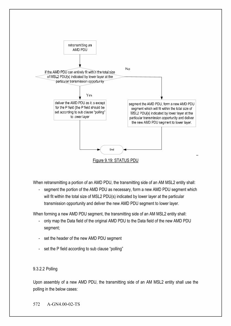
572 A-GN4.00-02-TS
Figure 9.19: STATUS PDU
When retransmitting a portion of an AMD PDU, the transmitting side of an AM MSL2 entity shall: - segment the portion of the AMD PDU as necessary, form a new AMD PDU segment which
will fit within the total size of MSL2 PDU(s) indicated by lower layer at the particular transmission opportunity and deliver the new AMD PDU segment to lower layer.
When forming a new AMD PDU segment, the transmitting side of an AM MSL2 entity shall: - only map the Data field of the original AMD PDU to the Data field of the new AMD PDU
segment;
- set the header of the new AMD PDU segment
- set the P field according to sub clause “polling”
9.3.2.2 Polling Upon assembly of a new AMD PDU, the transmitting side of an AM MSL2 entity shall use the polling in the below cases:

A-GN4.00-02-TS 573
- PDU_WITHOUT_POLL >= pollPDU - BYTE_WITHOUT_POLL >= pollByte - If both the transmission buffer and the retransmission buffer becomes empty (excluding transmitted MSL2 data PDU awaiting for acknowledgements) after the transmission of the MSL2 data PDU - If no new MSL2 data PDU can be transmitted after the transmission of the MSL2 data PDU (e.g. due to window stalling) To include a poll in a MSL2 data PDU, the transmitting side of an AM MSL2 entity shall:
- set the P field of the MSL2 data PDU to "1";
- set PDU_WITHOUT_POLL to 0;
- set BYTE_WITHOUT_POLL to 0;
After delivering a MSL2 data PDU including a poll to lower layer and after incrementing of VT(S) if necessary, the transmitting side of an AM MSL2 entity shall:
- set POLL_SN to VT(S) – 1 ;
- start t-PollRetransmit or restart t-PollRetransmit
9.3.2.3 Status report An AM MSL2 entity sends STATUS PDUs to its peer AM MSL2 entity in order to provide positive and/or negative acknowledgements of MSL2 PDUs (or portions of them). High layer configures whether or not the status prohibit function is to be used for an AM MSL2 entity. Triggers to initiate STATUS reporting include:
- Polling from its peer AM MSL2 entity:
- Detection of reception failure of an MSL2 data PDU:
STATUS PDU consists of a STATUS PDU payload and a MSL2 control PDU header. MSL2 control PDU header consists of a D/C and a CPT field. The STATUS PDU payload starts from the first bit following the MSL2 control PDU header, and it consists of one ACK_SN and one E1, zero or more sets of a NACK_SN, an E1 and an E2, and possibly a set of a SOstart and a SOend for each NACK_SN. When necessary one to seven padding bits are included in the end of the STATUS PDU to achieve octet alignment.

574 A-GN4.00-02-TS
Figure 9.20: STATUS PDU
9.4 QCS and Connection Figure 9.21 shows the relation between connection and QCS. The connection is related to unit radio resource. The radio resource is composed of CSCH or the pair of ANCH and EXCH. One connection accommodates one or more QCS. QoS is controlled for each QCS. One MS can have two or more connections. Detail of QoS is described in the following section. The connection is identified by connection-ID. The QCS is identified by QCS-ID.
Connection #1
MS
Connection #2
BS
QCSID=1 is only used for message.It is assigned per Connection ID.
QCS-ID=2 ~16 is used for user data.(ex. data, voice and others.)
Figure 9.21 Connection and QCS
The relation between connection and QCS is shown in Figure 9.21

A-GN4.00-02-TS 575
The value 1 of QCS-ID is used to transmit the connection and QCS control information. The value 2 to 16 of QCS-ID is used to transmit the upper layer data. The MAC control protocol is applied with all QCS-ID. This QCS-ID assignment is applied per connection.
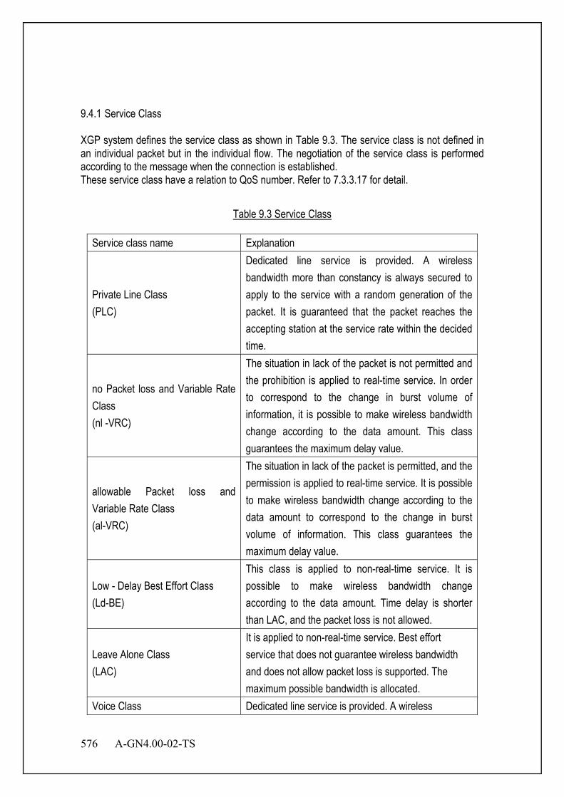
576 A-GN4.00-02-TS
9.4.1 Service Class XGP system defines the service class as shown in Table 9.3. The service class is not defined in an individual packet but in the individual flow. The negotiation of the service class is performed according to the message when the connection is established. These service class have a relation to QoS number. Refer to 7.3.3.17 for detail.
Table 9.3 Service Class
Service class name Explanation
Private Line Class (PLC)
Dedicated line service is provided. A wireless bandwidth more than constancy is always secured to apply to the service with a random generation of the packet. It is guaranteed that the packet reaches the accepting station at the service rate within the decided time.
no Packet loss and Variable Rate Class (nl -VRC)
The situation in lack of the packet is not permitted and the prohibition is applied to real-time service. In order to correspond to the change in burst volume of information, it is possible to make wireless bandwidth change according to the data amount. This class guarantees the maximum delay value.
allowable Packet loss and Variable Rate Class (al-VRC)
The situation in lack of the packet is permitted, and the permission is applied to real-time service. It is possible to make wireless bandwidth change according to the data amount to correspond to the change in burst volume of information. This class guarantees the maximum delay value.
Low - Delay Best Effort Class (Ld-BE)
This class is applied to non-real-time service. It is possible to make wireless bandwidth change according to the data amount. Time delay is shorter than LAC, and the packet loss is not allowed.
Leave Alone Class (LAC)
It is applied to non-real-time service. Best effort service that does not guarantee wireless bandwidth and does not allow packet loss is supported. The maximum possible bandwidth is allocated.
Voice Class Dedicated line service is provided. A wireless

A-GN4.00-02-TS 577
Service class name Explanation (Voice) bandwidth more than constancy is always secured to
apply to the service with a random generation. The quality of bandwidth and delay time is guaranteed by TCH which is defined for voice only channel.
9.4.2 QoS Parameter Table 9.4 shows the parameter guaranteed in each QoS service class.
Table 9.4 Service Class and Quality Parameter
QoS parameter Traffic parameter Forwarding delay
Jitter FER Guarantee bandwidth
Average Bit Rate
Traffic Priority
PLC Yes - Yes Yes Yes Yes nl-VRC, al-VRC
- Yes Yes Yes Yes Yes
LD-BE - - No No Yes Yes LAC - - No No No Yes Voice Yes - Yes Yes Yes Yes
Yes : Possible to specify it. No : Impossible to specify it. - : Irrelevance
9.4.2.1 Forwarding Delay The forwarding delay provided by this parameter is guaranteed in PLC of real-time service. 9.4.2.2 Jitter It refers to difference between the maximum delay value and the minimum delay value, as ell as the maximum jitter values.

578 A-GN4.00-02-TS
9.4.2.3 Frame Error Rate (FER) In real-time service, it provides the FER that service allows according to this parameter. 9.4.2.4 Guarantee Bandwidth The system guarantees the bandwidth provided by this parameter. It aims to transmit data without causing the delay when data transmission is needed by securing a necessary bandwidth without fail. 9.4.2.5 Average Bit Rate It is a bit number of the data transmitted to a wireless section near the unit time. It provides for the bit number of the data taken out of the made queue of each user (mean value). In Private Line Class, the average bit rate becomes the same as the guaranteed maximum bit rate because the data volume is constant. A wireless bandwidth is prevented from being occupied when data is generated in the burst as service provide output bit rate with high priority. 9.4.2.6 Traffic Priority This parameter is used when data in the same QoS class is given priority for process. For instance, when data requested for re-sending is made prior to usual data, the traffic priority is specified high.
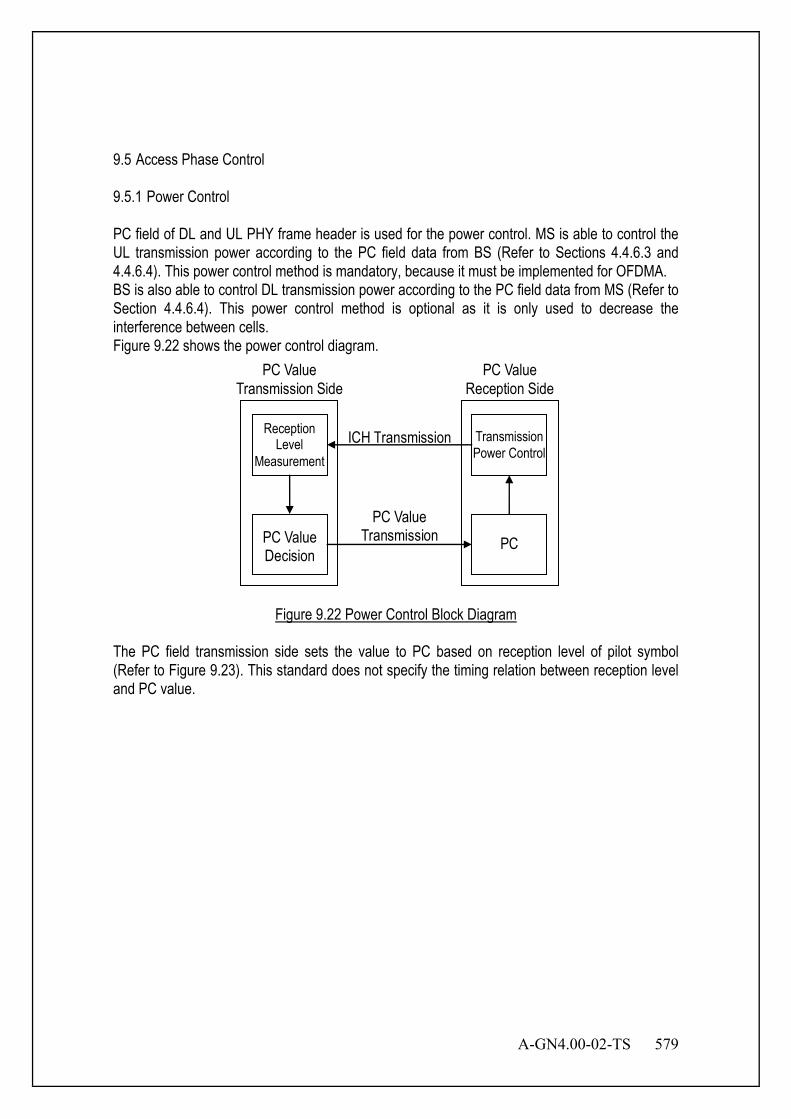
A-GN4.00-02-TS 579
9.5 Access Phase Control 9.5.1 Power Control PC field of DL and UL PHY frame header is used for the power control. MS is able to control the UL transmission power according to the PC field data from BS (Refer to Sections 4.4.6.3 and 4.4.6.4). This power control method is mandatory, because it must be implemented for OFDMA. BS is also able to control DL transmission power according to the PC field data from MS (Refer to Section 4.4.6.4). This power control method is optional as it is only used to decrease the interference between cells. Figure 9.22 shows the power control diagram.
Reception Level
Measurement
PC Value Decision
PC
Transmission Power Control
PC Value Transmission
ICH Transmission
PC Value Reception Side
PC Value Transmission Side
Figure 9.22 Power Control Block Diagram
The PC field transmission side sets the value to PC based on reception level of pilot symbol (Refer to Figure 9.23). This standard does not specify the timing relation between reception level and PC value.

580 A-GN4.00-02-TS
PC=0
PC
=1 Re
cepti
on Le
vel
Target Level
Figure 9.23 Reception Level and PC Value
The relation between the reception level and value of PC is shown below. • Reception level > Target level
PC=0 • Reception level <= Target level
PC=1 9.5.2 Timing Control SD field of DL PHY frame is used for the timing control. According to the SD field data from BS, MS is able to control the UL transmission timing (Refer to Section 4.4.6.2). Figure 9.24 shows the timing control diagram. BS aligns symbol timing between MS and MS by using SD field. BS decides SD value based on reception symbol timing. MS changes transmission timing according to SD.
SD Value Decision
SD
Timing Alignment
SD Value Transmission
ICH Transmission
MS BS
Timing Measurement
Figure 9.24 UL Timing Control Block Diagram
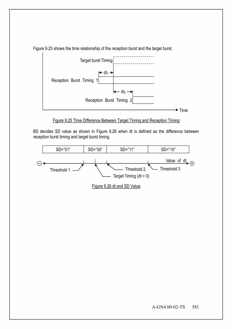
A-GN4.00-02-TS 581
Figure 9.25 shows the time relationship of the reception burst and the target burst.
Target burst Timing
Reception Burst Timing 1
Reception Burst Timing 2
dt1
dt2
Time
Figure 9.25 Time Difference Between Target Timing and Reception Timing
BS decides SD value as shown in Figure 9.26 when dt is defined as the difference between reception burst timing and target burst timing.
SD=”00” SD=”01” SD=”11” SD=”10”
Threshold 1Target Timing (dt = 0)
Threshold 2 Threshold 3
Value of dt
Figure 9.26 dt and SD Value
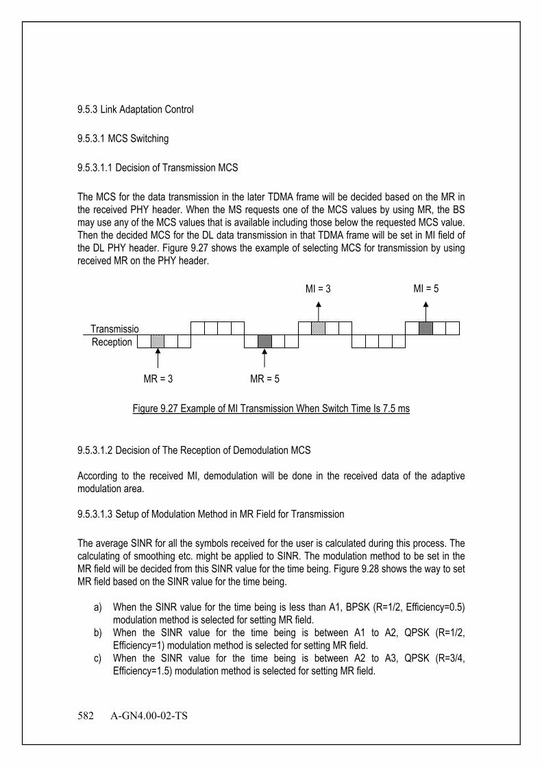
582 A-GN4.00-02-TS
9.5.3 Link Adaptation Control 9.5.3.1 MCS Switching 9.5.3.1.1 Decision of Transmission MCS The MCS for the data transmission in the later TDMA frame will be decided based on the MR in the received PHY header. When the MS requests one of the MCS values by using MR, the BS may use any of the MCS values that is available including those below the requested MCS value. Then the decided MCS for the DL data transmission in that TDMA frame will be set in MI field of the DL PHY header. Figure 9.27 shows the example of selecting MCS for transmission by using received MR on the PHY header.
Figure 9.27 Example of MI Transmission When Switch Time Is 7.5 ms
9.5.3.1.2 Decision of The Reception of Demodulation MCS According to the received MI, demodulation will be done in the received data of the adaptive modulation area. 9.5.3.1.3 Setup of Modulation Method in MR Field for Transmission The average SINR for all the symbols received for the user is calculated during this process. The calculating of smoothing etc. might be applied to SINR. The modulation method to be set in the MR field will be decided from this SINR value for the time being. Figure 9.28 shows the way to set MR field based on the SINR value for the time being.
a) When the SINR value for the time being is less than A1, BPSK (R=1/2, Efficiency=0.5) modulation method is selected for setting MR field.
b) When the SINR value for the time being is between A1 to A2, QPSK (R=1/2, Efficiency=1) modulation method is selected for setting MR field.
c) When the SINR value for the time being is between A2 to A3, QPSK (R=3/4, Efficiency=1.5) modulation method is selected for setting MR field.
Reception Transmissio
MR = 3 MR = 5
MI = 3 MI = 5
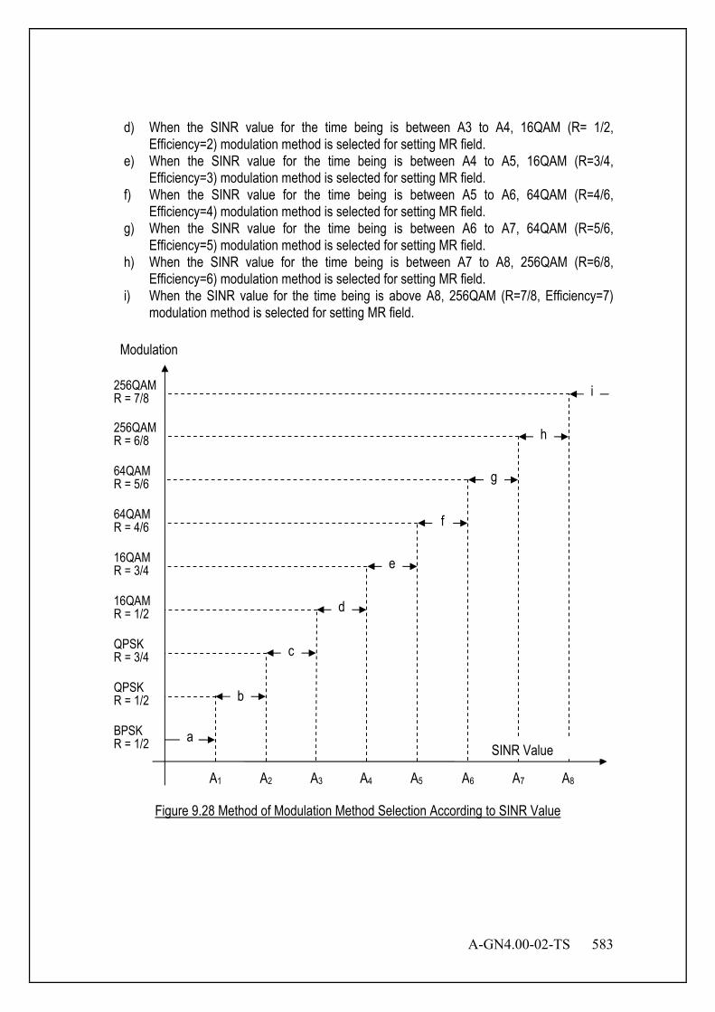
A-GN4.00-02-TS 583
d) When the SINR value for the time being is between A3 to A4, 16QAM (R= 1/2, Efficiency=2) modulation method is selected for setting MR field.
e) When the SINR value for the time being is between A4 to A5, 16QAM (R=3/4, Efficiency=3) modulation method is selected for setting MR field.
f) When the SINR value for the time being is between A5 to A6, 64QAM (R=4/6, Efficiency=4) modulation method is selected for setting MR field.
g) When the SINR value for the time being is between A6 to A7, 64QAM (R=5/6, Efficiency=5) modulation method is selected for setting MR field.
h) When the SINR value for the time being is between A7 to A8, 256QAM (R=6/8, Efficiency=6) modulation method is selected for setting MR field.
i) When the SINR value for the time being is above A8, 256QAM (R=7/8, Efficiency=7) modulation method is selected for setting MR field.
Figure 9.28 Method of Modulation Method Selection According to SINR Value
A1 A2 A3 A4 A5 A6 A7 A8
a
b
c
d
e
f
g
h
i 256QAM R = 7/8
256QAM R = 6/8
64QAM R = 5/6
64QAM R = 4/6
16QAM R = 3/4
16QAM R = 1/2
QPSK R = 3/4
QPSK R = 1/2
BPSK R = 1/2
Modulation
SINR Value

584 A-GN4.00-02-TS
9.5.4 ANCH/CSCH Scheduling Control Figure 9.29 shows numbering rule regarding ANCH/CSCH active frame. Both MS and BS use specified frames. It is called ANCH/CSCH active frame. Scheduling term is repeated during DL LCCH transmission period.
F1
UL DL
UL DL
CCH
ANCH/ CSCH
F2 Fn F1 F2
Downlink LCCH Transmission Period
1 TDMA Frame
F1 F2
Scheduling Term
Figure 9.29 ANCH/CSCH Active Frame Number
ANCH/CSCH active frame is changed by “ANCH/CSCH switching indication” message from BS in active state. Figure 9.30 and Figure 9.31 shows the change sequence of ANCH/CSCH active frame.
MS BS
ANCH/CSCH switching indication
ANCH/CSCH switching confirmation
Figure 9.30 BS Origin ANCH/CSCH Scheduling Change

A-GN4.00-02-TS 585
MS BS
ANCH/CSCH switching request
ANCH/CSCH switching indication
ANCH/CSCH switching confirmation
Figure 9.31 MS Origin ANCH/CSCH Scheduling Change
MS changes ANCH/CSCH active frame when MS receives ANCH/CSCH switching indication message. ANCH/CSCH switching indication message contains the following information.
• destination logical PRU number. which is the same as the source PRU or is a different PRU
• ANCH/CSCH scheduling term • ANCH/CSCH frame specification
MS sends ANCH/CSCH switching confirmation message after MS changes ANCH/CSCH active frame. When MS receives indication message which has unsupported value of scheduling term, period and scheduling itself, MS can request another scheduling term, period or reject the scheduling. The rejection of scheduling can be used only when there is the necessity for the guaranteed bandwidth such as voice data. 9.5.5 Interference Avoidance Control 9.5.5.1 ANCH/CSCH Disconnect Detection At the BS or MS, if the ANCH/CSCH reception is impossible for N successive times, the ANCH/CSCH will be released as the reception side regards the ANCH/CSCH to be disconnected. Figure 9.32 shows a sequence when ANCH/CSCH disconnection is detected at the BS side. If the N successive ANCH/CSCH disconnection does not happen, the BS will regard ANCH/CSCH to be connected. The ANCH will be released if the ANCH/CSCH is failed for the connection for N times continuously. It means transmission and reception on the ANCH/CSCH is ceased. Disconnection is detected in the same procedure at the MS. Both BS and MS regard it as an idle state after ANCH/CSCH is released.

586 A-GN4.00-02-TS
Figure 9.32 Detection of ANCH/CSCH Disconnection
9.5.5.2 ANCH/CSCH Switching MS supervises the average SINR on the DL ANCH while BS supervises the average SINR on the UL ANCH. When the radio condition deteriorates, ANCH/CSCH will be changed to another PRU. Average SINR is calculated according to the average SINR calculation time for ANCH/CSCH. The measurement result older than the average SINR calculation time for the ANCH/CSCH is not included in the calculation average SINR.
MS BS
ANCH ANCH ANCH ANCH ANCH
Releas
Tx Off
Releas
Tx Off
Idle State
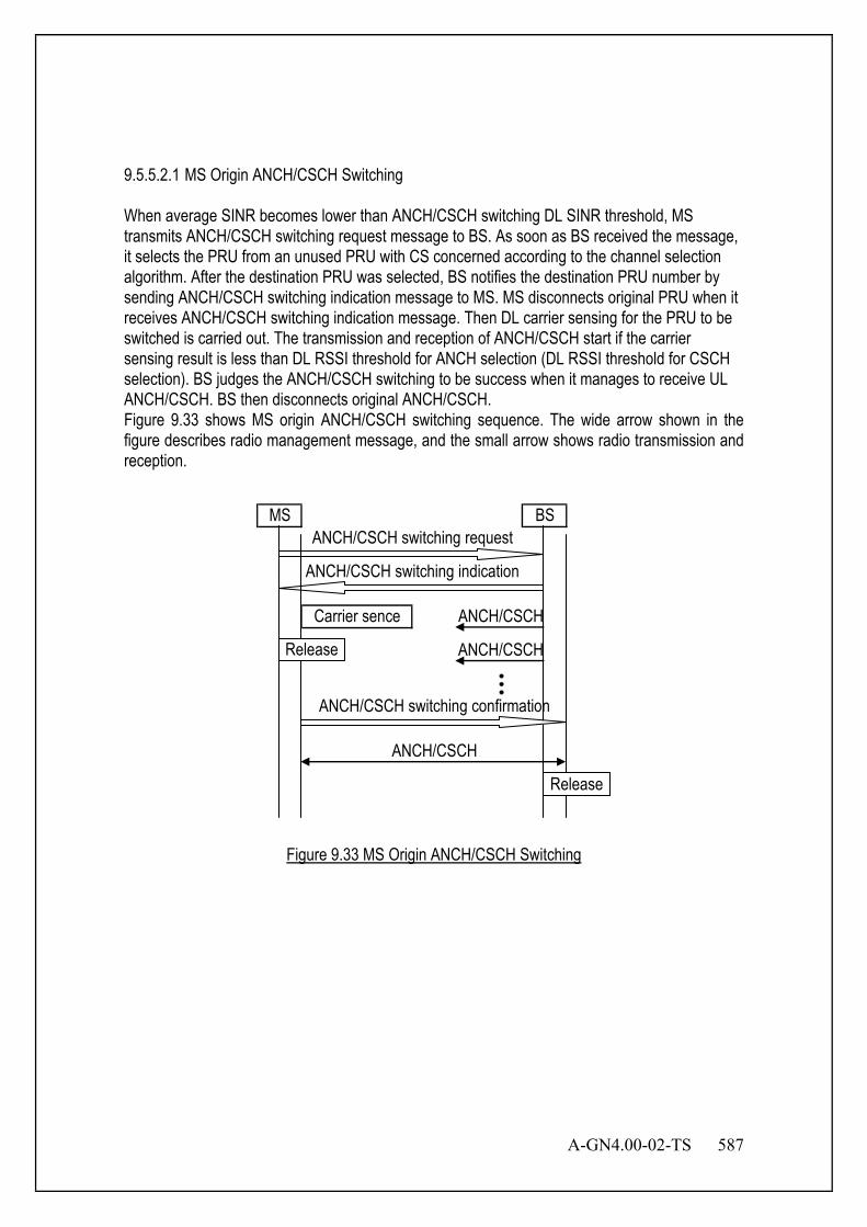
A-GN4.00-02-TS 587
9.5.5.2.1 MS Origin ANCH/CSCH Switching When average SINR becomes lower than ANCH/CSCH switching DL SINR threshold, MS transmits ANCH/CSCH switching request message to BS. As soon as BS received the message, it selects the PRU from an unused PRU with CS concerned according to the channel selection algorithm. After the destination PRU was selected, BS notifies the destination PRU number by sending ANCH/CSCH switching indication message to MS. MS disconnects original PRU when it receives ANCH/CSCH switching indication message. Then DL carrier sensing for the PRU to be switched is carried out. The transmission and reception of ANCH/CSCH start if the carrier sensing result is less than DL RSSI threshold for ANCH selection (DL RSSI threshold for CSCH selection). BS judges the ANCH/CSCH switching to be success when it manages to receive UL ANCH/CSCH. BS then disconnects original ANCH/CSCH. Figure 9.33 shows MS origin ANCH/CSCH switching sequence. The wide arrow shown in the figure describes radio management message, and the small arrow shows radio transmission and reception.
ANCH/CSCH
ANCH/CSCH switching indication
Carrier sence ANCH/CSCH
ANCH/CSCH
MS BSANCH/CSCH switching request
ANCH/CSCH switching confirmation
Release
Release
Figure 9.33 MS Origin ANCH/CSCH Switching
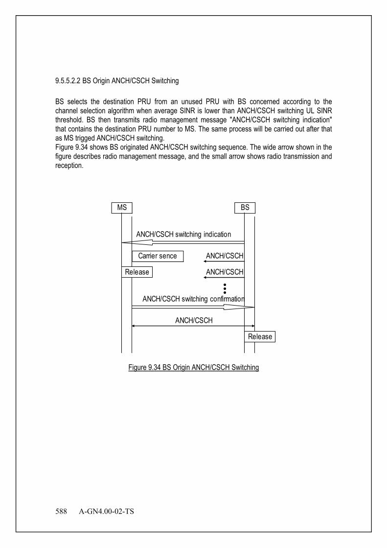
588 A-GN4.00-02-TS
9.5.5.2.2 BS Origin ANCH/CSCH Switching BS selects the destination PRU from an unused PRU with BS concerned according to the channel selection algorithm when average SINR is lower than ANCH/CSCH switching UL SINR threshold. BS then transmits radio management message "ANCH/CSCH switching indication" that contains the destination PRU number to MS. The same process will be carried out after that as MS trigged ANCH/CSCH switching. Figure 9.34 shows BS originated ANCH/CSCH switching sequence. The wide arrow shown in the figure describes radio management message, and the small arrow shows radio transmission and reception.
ANCH/CSCH
ANCH/CSCH switching indication
Carrier sence ANCH/CSCH
ANCH/CSCH
MS BS
ANCH/CSCH switching confirmation
Release
Release
Figure 9.34 BS Origin ANCH/CSCH Switching

A-GN4.00-02-TS 589
9.5.5.2.3 Retransmission of ANCH/CSCH Switching Indication UL transmission for original ANCH/CSCH is only able to be detected until retransmission timer expiration when BS transmits ANCH/CSCH switching indication message, BS then judges that ANCH/CSCH switching indication message did not reach MS and it retransmits ANCH/CSCH switching indication message.
MS BS
ANCH/CSCH switching indication
ANCH/CSCH
ANCH/CSCH
ANCH/CSCH switching indication
Retransmission Timer
Retransmission Timer
Figure 9.35 Retransmission of ANCH Switch Indication
When retrying count for ANCH/CSCH retransmission indication is over, ANCH/CSCH switching operation is finished and the original communication is continued. 9.5.5.2.4 Switchback Operation BS continues original ANCH/CSCH transmission and reception after the transmission of ANCH/CSCH switching indication message transmission because MS carries out switch back processing in case ANCH/CSCH switching fails. When the following conditions are satisfied at MS side, the switchback operation is carried out.
• When the DL carrier sensing result at the destination PRU exceeds the DL RSSI threshold for ANCH selection (DL RSSI threshold for CSCH selection).
• When DL ANCH/CSCH is not detected at destination PRU.
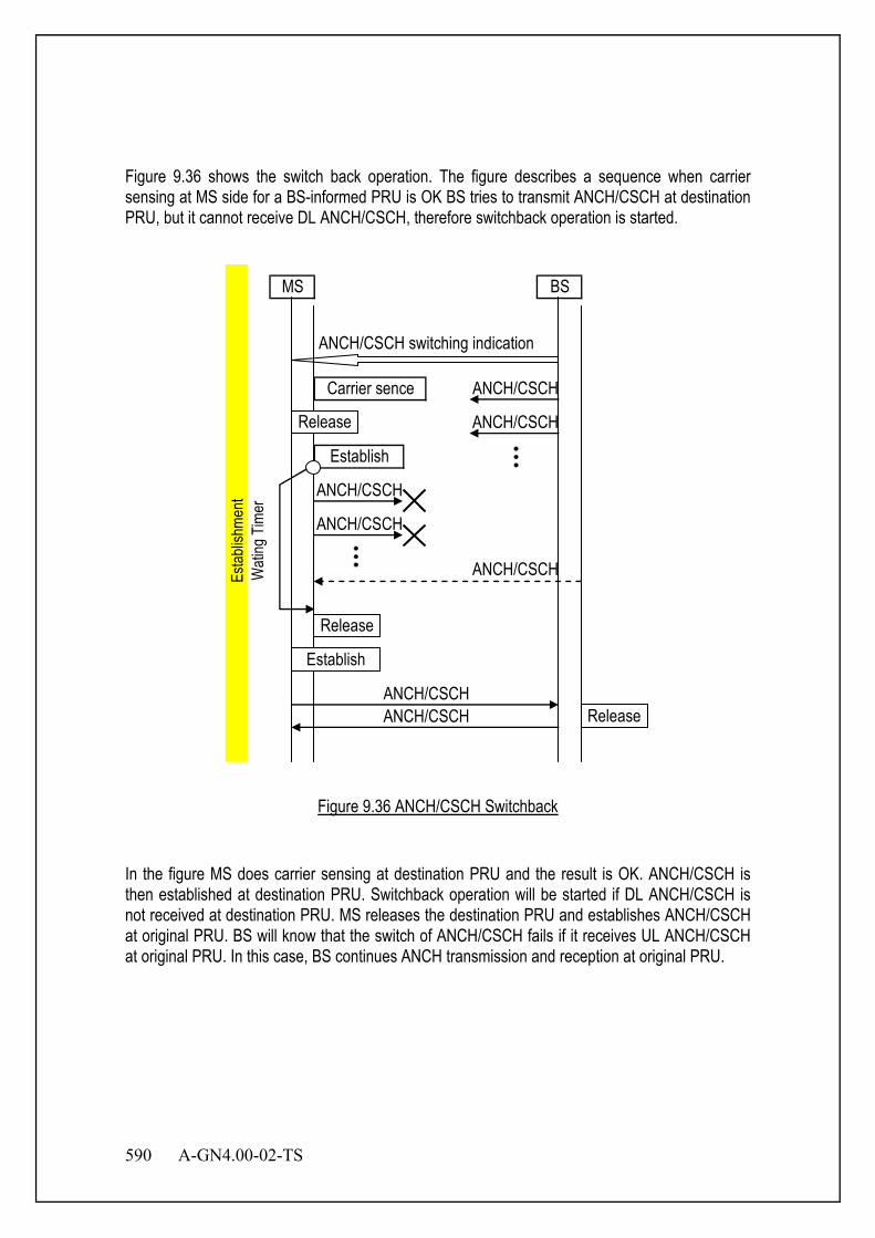
590 A-GN4.00-02-TS
Figure 9.36 shows the switch back operation. The figure describes a sequence when carrier sensing at MS side for a BS-informed PRU is OK BS tries to transmit ANCH/CSCH at destination PRU, but it cannot receive DL ANCH/CSCH, therefore switchback operation is started.
MS BS
Establish
ANCH/CSCH switching indication
Carrier sence ANCH/CSCH
ANCH/CSCH
ANCH/CSCHANCH/CSCH
ANCH/CSCH
ANCH/CSCH
ANCH/CSCH
Release
Release
Release
Establish
Estab
lishm
ent
Wati
ng T
imer
Figure 9.36 ANCH/CSCH Switchback
In the figure MS does carrier sensing at destination PRU and the result is OK. ANCH/CSCH is then established at destination PRU. Switchback operation will be started if DL ANCH/CSCH is not received at destination PRU. MS releases the destination PRU and establishes ANCH/CSCH at original PRU. BS will know that the switch of ANCH/CSCH fails if it receives UL ANCH/CSCH at original PRU. In this case, BS continues ANCH transmission and reception at original PRU.
A-GN4.00-02-TS 591
9.5.6 Handover Control There are two kinds of handover procedure definition for XGP. One is normal handover, of which the processing is started after all the radio connections with BS are disconnected. The other is seamless handover, of which the processing is started with no need to disconnect the BS in connection. Seamless handover can be carried out with less overhead.
When MS is handed over to BS, connection establishment procedure is conducted in the same way. MS transmits LCH assignment request message to BS-B which is selected by MS according to each procedure. After MS receives LCH assignment message from BS-B, MS carries out transmission by changing radio state from idle to active and connecting ANCH/CSCH. After connection is established to BS-B, resource release operation is carried out from network side of BS-A. BS-A : The BS from which the MS is handed over. BS-B : The BS to which the MS is being handed over.
9.5.6.1 Normal Handover MS starts connection establishment processing after stopping CCH capture and ICH transmission/reception. The conditions to start normal handover are describes as follows.
• When DL ANCH/CSCH disconnection is detected at less RSSI value for DL ANCH/CSCH than the threshold of handover processing level.
• When the RSSI value of UL ANCH/CSCH is less than threshold of handover processing level.
• When BS cannot assign PRU to be switched although ANCH/CSCH switching condition is satisfied.
“ANCH/CSCH switching indication” message is transmitted from BS to MS in case when BS starts normal handover. MS starts normal handover when it receives the message. Once of MS starts normal handover, it will not transmit any signal to BS to inform the start of handover processing. MS starts the search for destination BS after transmission stops. The result of the search for destination BS is arranged in order of RSSI value from the highest one on. When the handover process starts, destination BS is chosen from the list which is created as a result of the search for destination BS. The BS which has indicated the highest RSSI value should be given the highest priority over all others for destination BS choice.
592 A-GN4.00-02-TS
9.5.6.2 Seamless Handover MS searches for destination BS while maintaining the connection to the original BS. Destination BS is chosen from information based on search result. The conditions to start seamless handover are as follows:
• when SINR of DL ANCH/CSCH becomes less than seamless handover SINR threshold. • when SINR of UL ANCH/CSCH becomes less than seamless handover processing
SINR. When the condition to start MS originated seamless handover is satisfied, LCH assignment request message will be transmitted from the MS to destination BS if MS has available destination BS list. If MS does not have available destination BS list, MS transmits ANCH/CSCH switching request [No destination BS list] message to the original BS to search for destination BS. When BS receives ANCH/CSCH switching request [No destination BS list], it allocates all EXCHs to the MS. If there is no EXCH allocation for the MS, the MS starts destination BS search processing at all TDMA slots except for the TDMA slot which ANCH/CSCH is allocated. In this case, The BS searching process is carried out to all relative slots except for the TDMA slot to which ANCH/CSCH is allocated. After the searching process for destination BS is completed, LCH assignment request message is transmitted to the destination BS. When MS receives LCH assignment reject message from destination BS, MS re-select destination BS from its own destination BS list, then seamless handover process is carried out again. When MS receives LCH assignment message from destination BS, ANCH/CSCH transmission and reception starts at destination BS without disconnecting radio link. When radio resource allocation is received from destination BS through MAP in DL ANCH/CSCH, radio link between original BS is disconnected.
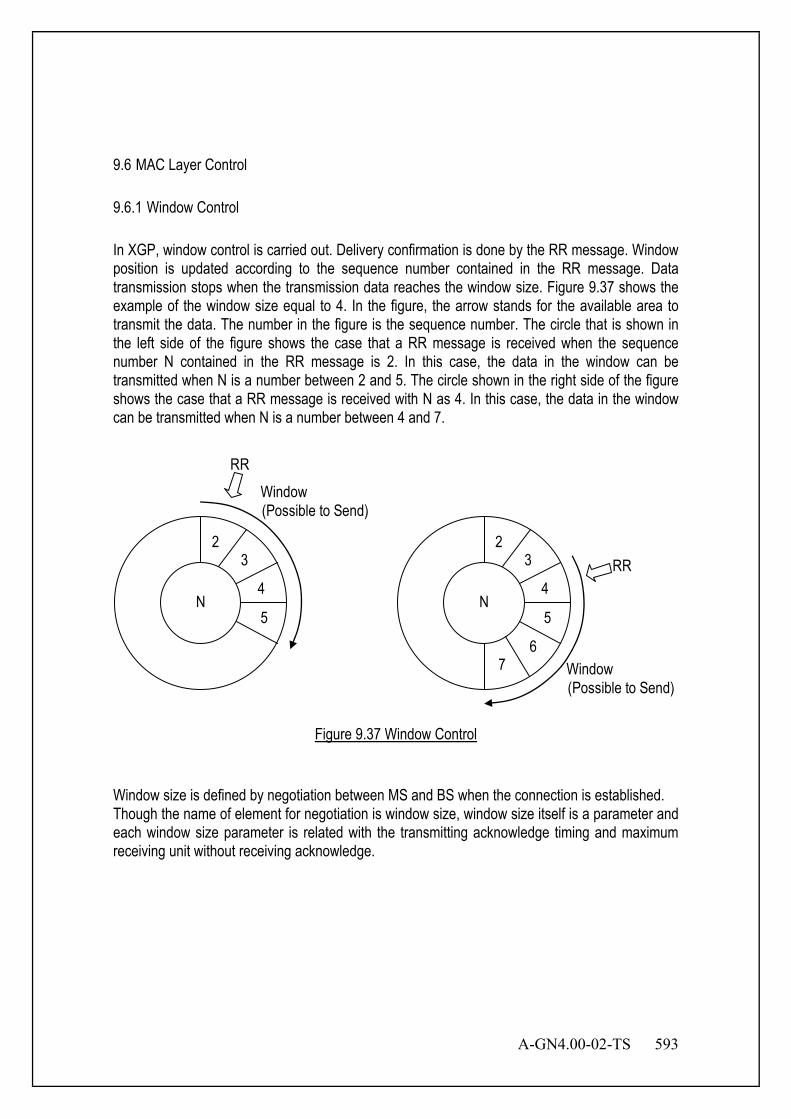
A-GN4.00-02-TS 593
9.6 MAC Layer Control 9.6.1 Window Control In XGP, window control is carried out. Delivery confirmation is done by the RR message. Window position is updated according to the sequence number contained in the RR message. Data transmission stops when the transmission data reaches the window size. Figure 9.37 shows the example of the window size equal to 4. In the figure, the arrow stands for the available area to transmit the data. The number in the figure is the sequence number. The circle that is shown in the left side of the figure shows the case that a RR message is received when the sequence number N contained in the RR message is 2. In this case, the data in the window can be transmitted when N is a number between 2 and 5. The circle shown in the right side of the figure shows the case that a RR message is received with N as 4. In this case, the data in the window can be transmitted when N is a number between 4 and 7.
N
23
4
5
Window (Possible to Send)
RR
N
23
4
5
67
RR
Window (Possible to Send)
Figure 9.37 Window Control
Window size is defined by negotiation between MS and BS when the connection is established. Though the name of element for negotiation is window size, window size itself is a parameter and each window size parameter is related with the transmitting acknowledge timing and maximum receiving unit without receiving acknowledge.
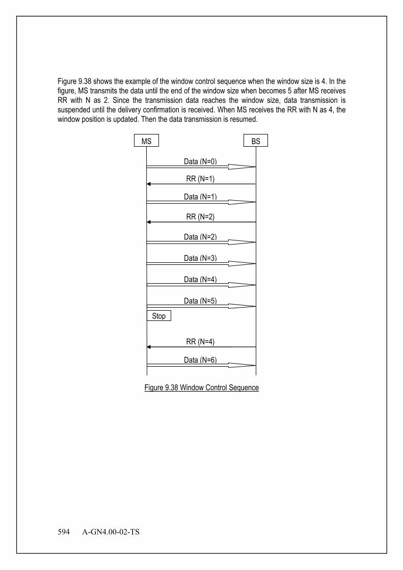
594 A-GN4.00-02-TS
Figure 9.38 shows the example of the window control sequence when the window size is 4. In the figure, MS transmits the data until the end of the window size when becomes 5 after MS receives RR with N as 2. Since the transmission data reaches the window size, data transmission is suspended until the delivery confirmation is received. When MS receives the RR with N as 4, the window position is updated. Then the data transmission is resumed.
MS BS
Data (N=0)
Stop
RR (N=1)
Data (N=1)
RR (N=2)
Data (N=2)
Data (N=3)
Data (N=4)
Data (N=5)
RR (N=4)
Data (N=6)
Figure 9.38 Window Control Sequence
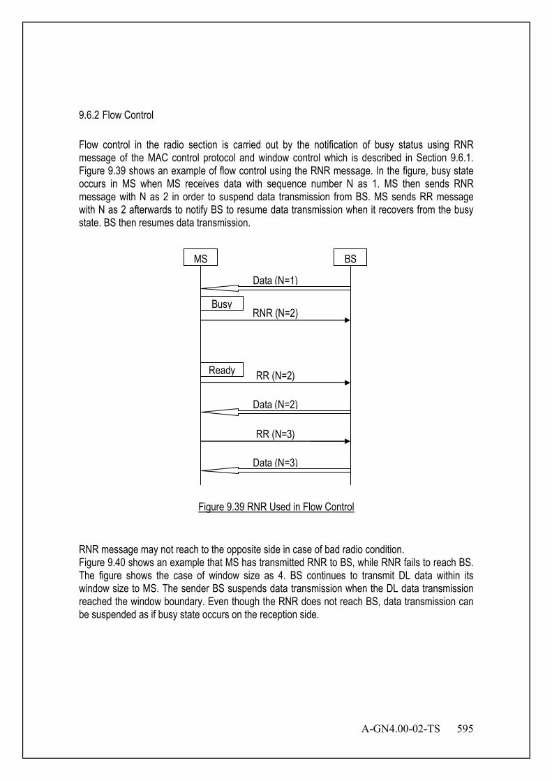
A-GN4.00-02-TS 595
9.6.2 Flow Control Flow control in the radio section is carried out by the notification of busy status using RNR message of the MAC control protocol and window control which is described in Section 9.6.1. Figure 9.39 shows an example of flow control using the RNR message. In the figure, busy state occurs in MS when MS receives data with sequence number N as 1. MS then sends RNR message with N as 2 in order to suspend data transmission from BS. MS sends RR message with N as 2 afterwards to notify BS to resume data transmission when it recovers from the busy state. BS then resumes data transmission.
MS BS
Data (N=1)
RNR (N=2)
Ready
Busy
RR (N=2)
Data (N=2)
RR (N=3)
Data (N=3)
Figure 9.39 RNR Used in Flow Control
RNR message may not reach to the opposite side in case of bad radio condition. Figure 9.40 shows an example that MS has transmitted RNR to BS, while RNR fails to reach BS. The figure shows the case of window size as 4. BS continues to transmit DL data within its window size to MS. The sender BS suspends data transmission when the DL data transmission reached the window boundary. Even though the RNR does not reach BS, data transmission can be suspended as if busy state occurs on the reception side.
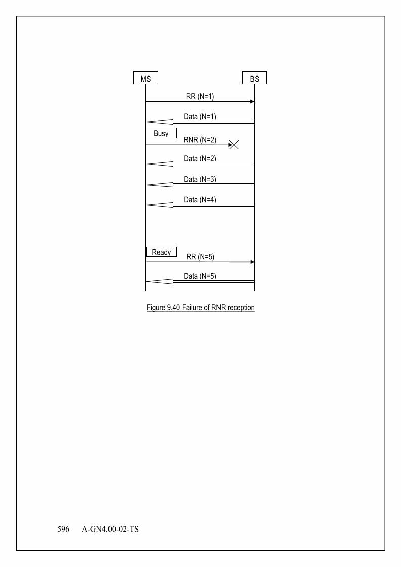
596 A-GN4.00-02-TS
MS BS
Data (N=1)
RNR (N=2)
Ready
Busy
Data (N=2)
RR (N=5)
Data (N=3)
RR (N=1)
Data (N=4)
Data (N=5)
Figure 9.40 Failure of RNR reception
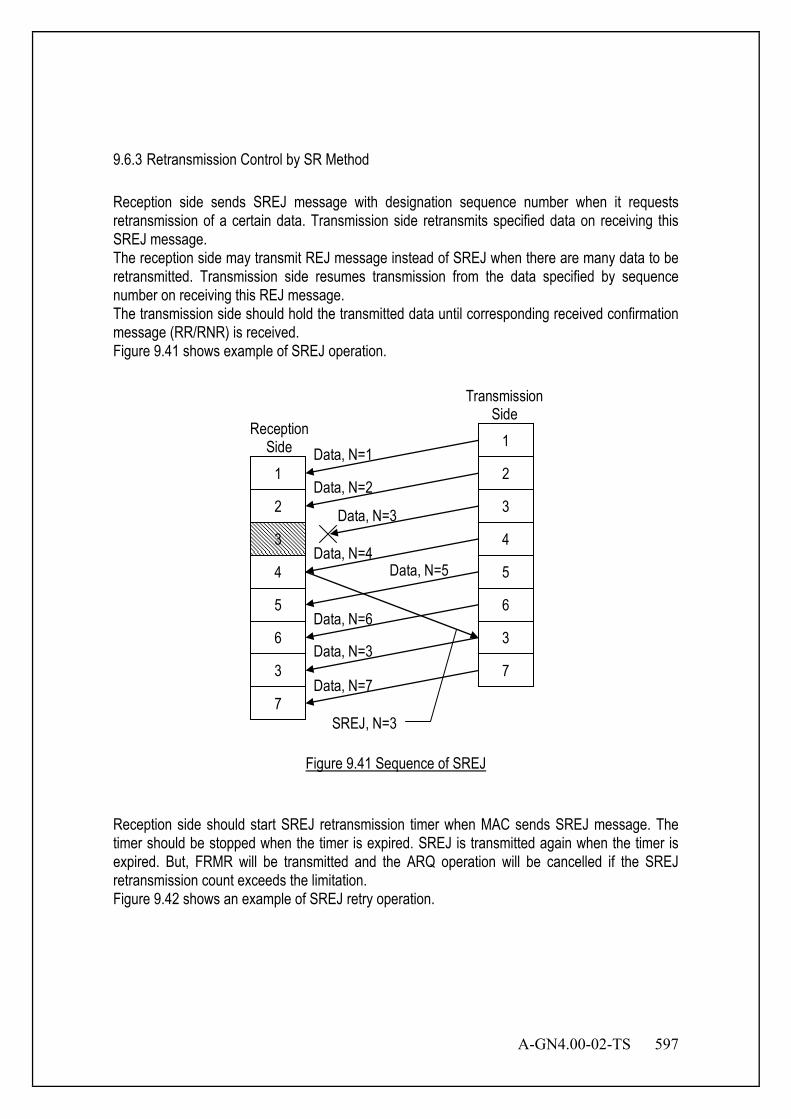
A-GN4.00-02-TS 597
9.6.3 Retransmission Control by SR Method Reception side sends SREJ message with designation sequence number when it requests retransmission of a certain data. Transmission side retransmits specified data on receiving this SREJ message. The reception side may transmit REJ message instead of SREJ when there are many data to be retransmitted. Transmission side resumes transmission from the data specified by sequence number on receiving this REJ message. The transmission side should hold the transmitted data until corresponding received confirmation message (RR/RNR) is received. Figure 9.41 shows example of SREJ operation.
1
2
3
4
5
6
3
7
1
2
3
4
5
6
3
7
Data, N=1
Data, N=2
Data, N=3
Data, N=4 Data, N=5
Data, N=6
Data, N=3
Data, N=7
SREJ, N=3
Transmission Side
Reception Side
Figure 9.41 Sequence of SREJ
Reception side should start SREJ retransmission timer when MAC sends SREJ message. The timer should be stopped when the timer is expired. SREJ is transmitted again when the timer is expired. But, FRMR will be transmitted and the ARQ operation will be cancelled if the SREJ retransmission count exceeds the limitation. Figure 9.42 shows an example of SREJ retry operation.

598 A-GN4.00-02-TS
Reception Side
Data (N=5)
Data (N=7)
Data (N=8)
SREJ (N=6)
Transmission Side
Data (N=6)
SREJ (N=6)
SREJ (N=6)
FRMR
TO
TO
TO
SREJ Retransmission Timer
SREJ Retransmission Timer
SREJ Retransmission Timer
Figure 9.42 MAC-ARQ SREJ Retry Operation
RR should be sent if reception side receives retransmitted data. Figure 9.43 shows an example of MAC-ARQ operation.
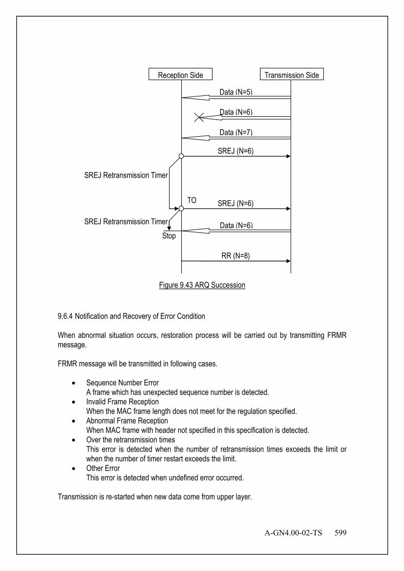
A-GN4.00-02-TS 599
Reception Side
Data (N=5)
Data (N=7)
SREJ (N=6)
Transmission Side
Data (N=6)
SREJ (N=6)
RR (N=8)
TO
SREJ Retransmission Timer
SREJ Retransmission Timer Data (N=6) Stop
Figure 9.43 ARQ Succession
9.6.4 Notification and Recovery of Error Condition When abnormal situation occurs, restoration process will be carried out by transmitting FRMR message. FRMR message will be transmitted in following cases.
• Sequence Number Error A frame which has unexpected sequence number is detected.
• Invalid Frame Reception When the MAC frame length does not meet for the regulation specified.
• Abnormal Frame Reception When MAC frame with header not specified in this specification is detected.
• Over the retransmission times This error is detected when the number of retransmission times exceeds the limit or when the number of timer restart exceeds the limit.
• Other Error This error is detected when undefined error occurred.
Transmission is re-started when new data come from upper layer.
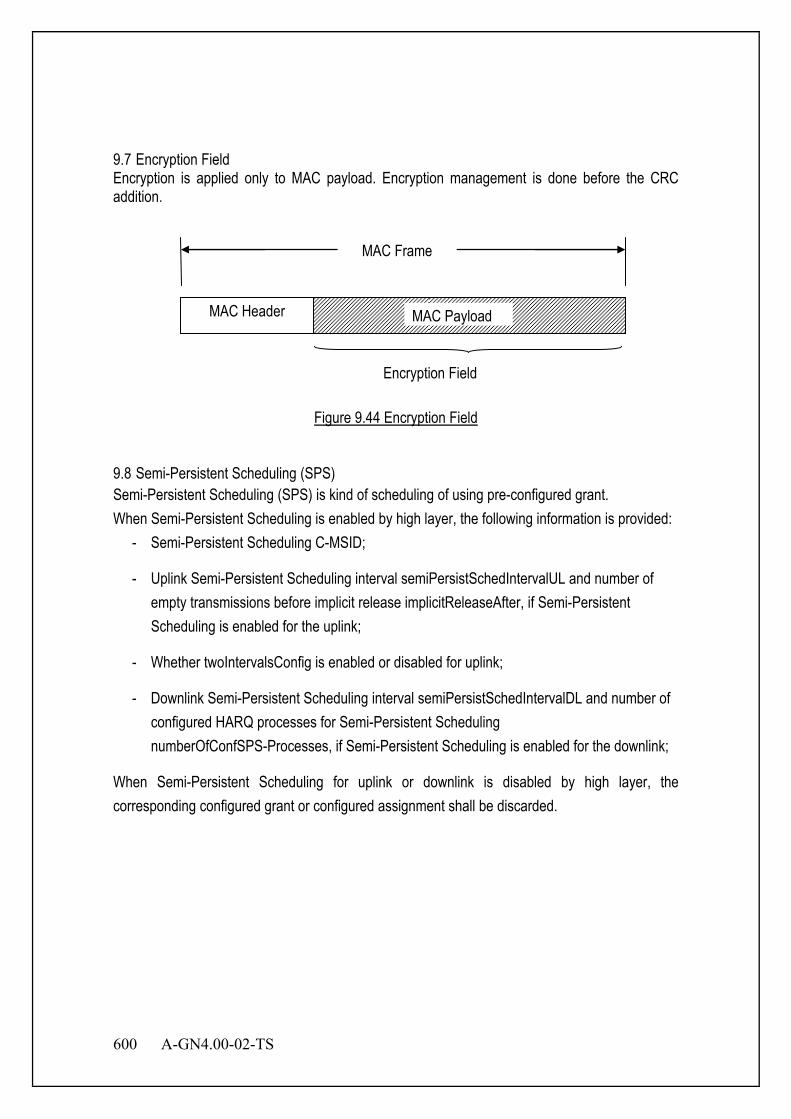
600 A-GN4.00-02-TS
9.7 Encryption Field Encryption is applied only to MAC payload. Encryption management is done before the CRC addition.
MAC Header
MAC Frame
Encryption Field
MAC Payload
Figure 9.44 Encryption Field
9.8 Semi-Persistent Scheduling (SPS) Semi-Persistent Scheduling (SPS) is kind of scheduling of using pre-configured grant. When Semi-Persistent Scheduling is enabled by high layer, the following information is provided:
- Semi-Persistent Scheduling C-MSID;
- Uplink Semi-Persistent Scheduling interval semiPersistSchedIntervalUL and number of empty transmissions before implicit release implicitReleaseAfter, if Semi-Persistent Scheduling is enabled for the uplink;
- Whether twoIntervalsConfig is enabled or disabled for uplink;
- Downlink Semi-Persistent Scheduling interval semiPersistSchedIntervalDL and number of configured HARQ processes for Semi-Persistent Scheduling numberOfConfSPS-Processes, if Semi-Persistent Scheduling is enabled for the downlink;
When Semi-Persistent Scheduling for uplink or downlink is disabled by high layer, the corresponding configured grant or configured assignment shall be discarded.
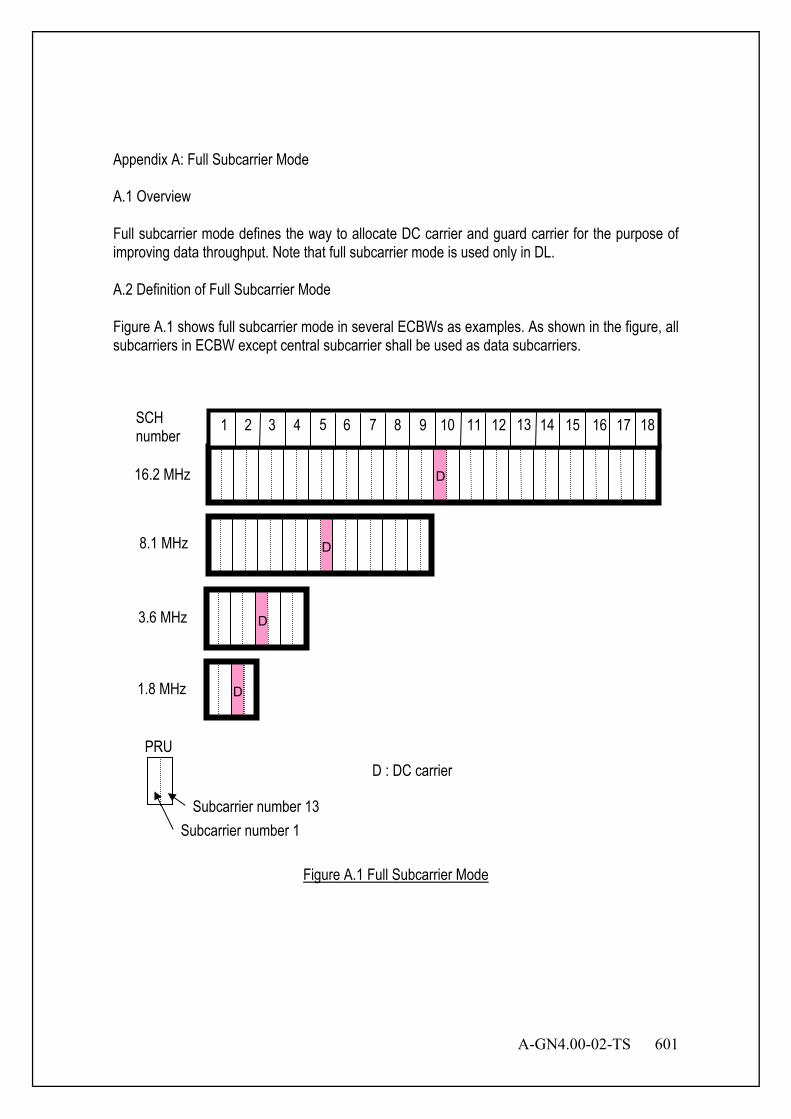
A-GN4.00-02-TS 601
Appendix A: Full Subcarrier Mode A.1 Overview Full subcarrier mode defines the way to allocate DC carrier and guard carrier for the purpose of improving data throughput. Note that full subcarrier mode is used only in DL. A.2 Definition of Full Subcarrier Mode Figure A.1 shows full subcarrier mode in several ECBWs as examples. As shown in the figure, all subcarriers in ECBW except central subcarrier shall be used as data subcarriers.
Figure A.1 Full Subcarrier Mode
SCH number
16.2 MHz
8.1 MHz
3.6 MHz
1.8 MHz
PRU
Subcarrier number 13 Subcarrier number 1
D : DC carrier
1 2 3 4 5 6 7 8 9 10 11 12 13 14 15 16 17 18
D
D
D
D
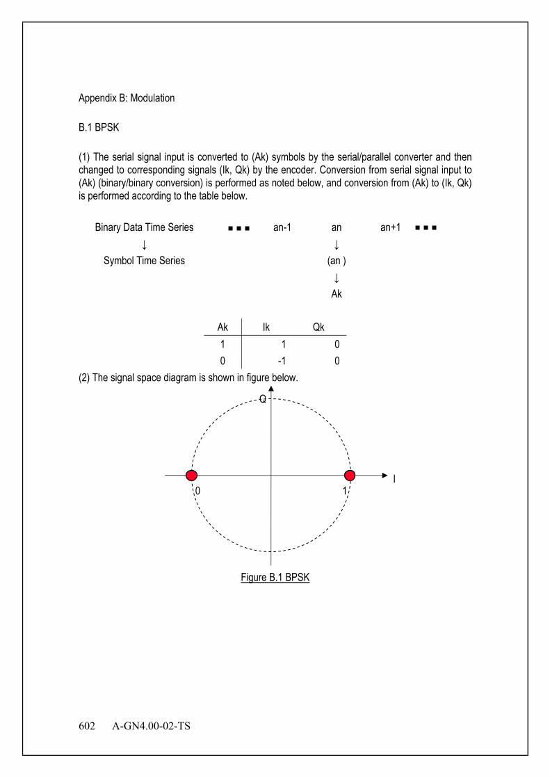
602 A-GN4.00-02-TS
Appendix B: Modulation B.1 BPSK (1) The serial signal input is converted to (Ak) symbols by the serial/parallel converter and then changed to corresponding signals (Ik, Qk) by the encoder. Conversion from serial signal input to (Ak) (binary/binary conversion) is performed as noted below, and conversion from (Ak) to (Ik, Qk) is performed according to the table below.
Binary Data Time Series an-1 an an+1 ↓ ↓
Symbol Time Series (an ) ↓ Ak
Ak Ik Qk 1 1 0 0 -1 0
(2) The signal space diagram is shown in figure below.
Figure B.1 BPSK
I
Q
1 0

A-GN4.00-02-TS 603
B.2 π/2 - BPSK (1) The serial signal input is converted to (A2k) or (A2k+1) symbols by the serial/parallel converter and then changed to corresponding signals (I2k, Q2k) or (I2k+1, Q2k+1) by the encoder. Conversion from serial signal input to (A2k) or (A2k+1) (binary/binary conversion) is performed as noted below, and conversion from (A2k) to (I2k, Q2k) or from (A2k+1) to (I2k+1, Q2k+1) is performed according to the table below.
Binary Data Time Series a2n-1 a2n a2n+1 ↓ ↓ ↓
Symbol Time Series (a2n) (a2n+1) ↓ ↓ A2k A2k+1
A2k I2k Q2k
1 1 0 0 -1 0
A2k+1 I2k+1 Q2k+1
1 0 -1 0 0 1
(2) The signal space diagram is shown in figure below.
Figure B.2 π/2 -BPSK
I
Q
1 0
0
1 : symbol of even number(2,4,…)
: symbol of odd number(1,3,5,…)

604 A-GN4.00-02-TS
B.3 QPSK (1) The serial signal input is converted to (Ak, Bk) symbols by the serial/parallel converter and then changed to corresponding signals (Ik, Qk) by the encoder. Conversion from serial signal input to (Ak, Bk) (binary/quaternary conversion) is performed as noted below, and conversion from (Ak, Bk) to (Ik, Qk) is performed according to the table below.
Binary Data Time Series an-1 an an+1 ↓ ↓ ↓
Symbol Time Series (an, an+1) ↓ ↓ Ak Bk
Ak Bk Ik Qk 1 1 1/√2 1/√2 1 0 1/√2 -1/√2 0 1 -1/√2 1/√2 0 0 -1/√2 -1/√2
(2) The signal space diagram is shown in the figure below.
Figure B.3 QPSK
I
Q
00 10
11 01
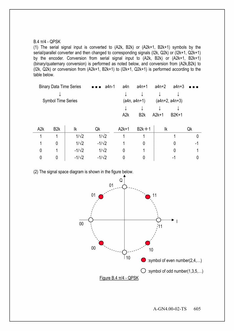
A-GN4.00-02-TS 605
B.4 π/4 - QPSK (1) The serial signal input is converted to (A2k, B2k) or (A2k+1, B2k+1) symbols by the serial/parallel converter and then changed to corresponding signals (I2k, Q2k) or (I2k+1, Q2k+1) by the encoder. Conversion from serial signal input to (A2k, B2k) or (A2k+1, B2k+1) (binary/quaternary conversion) is performed as noted below, and conversion from (A2k,B2k) to (I2k, Q2k) or conversion from (A2k+1, B2k+1) to (I2k+1, Q2k+1) is performed according to the table below.
Binary Data Time Series a4n-1 a4n a4n+1 a4n+2 a4n+3 ↓ ↓ ↓ ↓ ↓
Symbol Time Series (a4n, a4n+1) (a4n+2, a4n+3) ↓ ↓ ↓ ↓ A2k B2k A2k+1 B2K+1
A2k B2k Ik Qk A2k+1 B2k+1 Ik Qk
1 1 1/√2 1/√2 1 1 1 0 1 0 1/√2 -1/√2 1 0 0 -1 0 1 -1/√2 1/√2 0 1 0 1 0 0 -1/√2 -1/√2 0 0 -1 0
(2) The signal space diagram is shown in the figure below.
Figure B.4 π/4 - QPSK
I
Q
00 10
11 01
11
10
00
01
:symbol of even number(2,4,…)
:symbol of odd number(1,3,5,…)
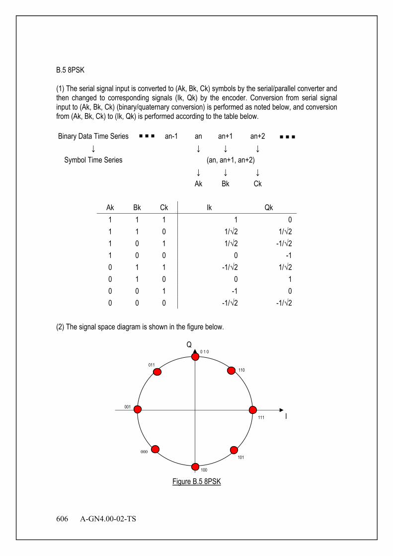
606 A-GN4.00-02-TS
B.5 8PSK (1) The serial signal input is converted to (Ak, Bk, Ck) symbols by the serial/parallel converter and then changed to corresponding signals (Ik, Qk) by the encoder. Conversion from serial signal input to (Ak, Bk, Ck) (binary/quaternary conversion) is performed as noted below, and conversion from (Ak, Bk, Ck) to (Ik, Qk) is performed according to the table below. Binary Data Time Series an-1 an an+1 an+2
↓ ↓ ↓ ↓ Symbol Time Series (an, an+1, an+2)
↓ ↓ ↓ Ak Bk Ck
Ak Bk Ck Ik Qk 1 1 1 1 0 1 1 0 1/√2 1/√2 1 0 1 1/√2 -1/√2 1 0 0 0 -1 0 1 1 -1/√2 1/√2 0 1 0 0 1 0 0 1 -1 0 0 0 0 -1/√2 -1/√2
(2) The signal space diagram is shown in the figure below.
Figure B.5 8PSK
I
Q
100
0 1 0
001
011 110
111
101 000
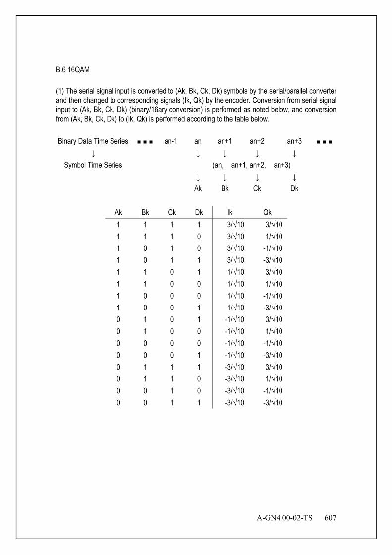
A-GN4.00-02-TS 607
B.6 16QAM (1) The serial signal input is converted to (Ak, Bk, Ck, Dk) symbols by the serial/parallel converter and then changed to corresponding signals (Ik, Qk) by the encoder. Conversion from serial signal input to (Ak, Bk, Ck, Dk) (binary/16ary conversion) is performed as noted below, and conversion from (Ak, Bk, Ck, Dk) to (Ik, Qk) is performed according to the table below. Binary Data Time Series an-1 an an+1 an+2 an+3
↓ ↓ ↓ ↓ ↓ Symbol Time Series (an, an+1, an+2, an+3)
↓ ↓ ↓ ↓ Ak Bk Ck Dk
Ak Bk Ck Dk Ik Qk 1 1 1 1 3/√10 3/√10 1 1 1 0 3/√10 1/√10 1 0 1 0 3/√10 -1/√10 1 0 1 1 3/√10 -3/√10 1 1 0 1 1/√10 3/√10 1 1 0 0 1/√10 1/√10 1 0 0 0 1/√10 -1/√10 1 0 0 1 1/√10 -3/√10 0 1 0 1 -1/√10 3/√10 0 1 0 0 -1/√10 1/√10 0 0 0 0 -1/√10 -1/√10 0 0 0 1 -1/√10 -3/√10 0 1 1 1 -3/√10 3/√10 0 1 1 0 -3/√10 1/√10 0 0 1 0 -3/√10 -1/√10 0 0 1 1 -3/√10 -3/√10
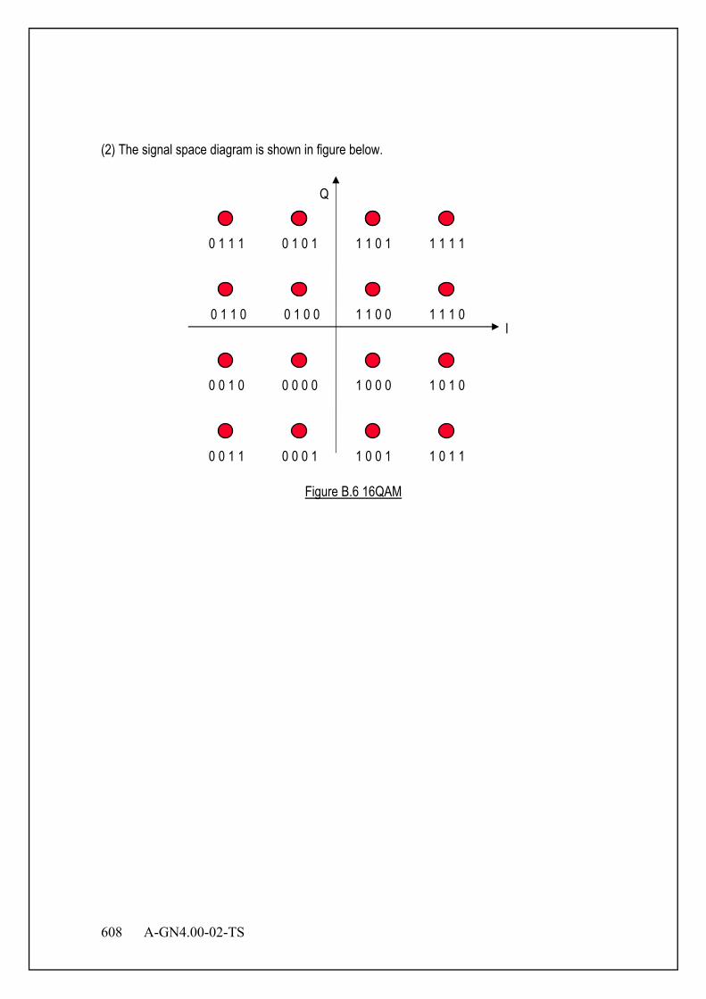
608 A-GN4.00-02-TS
(2) The signal space diagram is shown in figure below.
Figure B.6 16QAM
I
Q
0 0 0 0
1 0 0 1 1 0 1 1
0 0 1 0
0 0 0 1
1 0 0 0 1 0 1 0
0 0 1 1
0 1 0 1
1 1 0 0 1 1 1 0
0 1 1 1
0 1 0 0
1 1 0 1 1 1 1 1
0 1 1 0
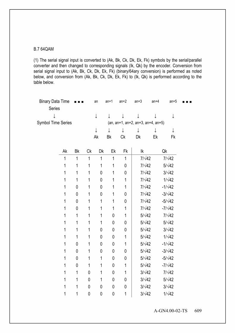
A-GN4.00-02-TS 609
B.7 64QAM (1) The serial signal input is converted to (Ak, Bk, Ck, Dk, Ek, Fk) symbols by the serial/parallel converter and then changed to corresponding signals (Ik, Qk) by the encoder. Conversion from serial signal input to (Ak, Bk, Ck, Dk, Ek, Fk) (binary/64ary conversion) is performed as noted below, and conversion from (Ak, Bk, Ck, Dk, Ek, Fk) to (Ik, Qk) is performed according to the table below.
Binary Data Time Series
an an+1 an+2 an+3 an+4 an+5
↓ ↓ ↓ ↓ ↓ ↓ ↓ Symbol Time Series (an, an+1, an+2, an+3, an+4, an+5) ↓ ↓ ↓ ↓ ↓ ↓ Ak Bk Ck Dk Ek Fk
Ak Bk Ck Dk Ek Fk Ik Qk 1 1 1 1 1 1 7/√42 7/√42 1 1 1 1 1 0 7/√42 5/√42 1 1 1 0 1 0 7/√42 3/√42 1 1 1 0 1 1 7/√42 1/√42 1 0 1 0 1 1 7/√42 -1/√42 1 0 1 0 1 0 7/√42 -3/√42 1 0 1 1 1 0 7/√42 -5/√42 1 0 1 1 1 1 7/√42 -7/√42 1 1 1 1 0 1 5/√42 7/√42 1 1 1 1 0 0 5/√42 5/√42 1 1 1 0 0 0 5/√42 3/√42 1 1 1 0 0 1 5/√42 1/√42 1 0 1 0 0 1 5/√42 -1/√42 1 0 1 0 0 0 5/√42 -3/√42 1 0 1 1 0 0 5/√42 -5/√42 1 0 1 1 0 1 5/√42 -7/√42 1 1 0 1 0 1 3/√42 7/√42 1 1 0 1 0 0 3/√42 5/√42 1 1 0 0 0 0 3/√42 3/√42 1 1 0 0 0 1 3/√42 1/√42
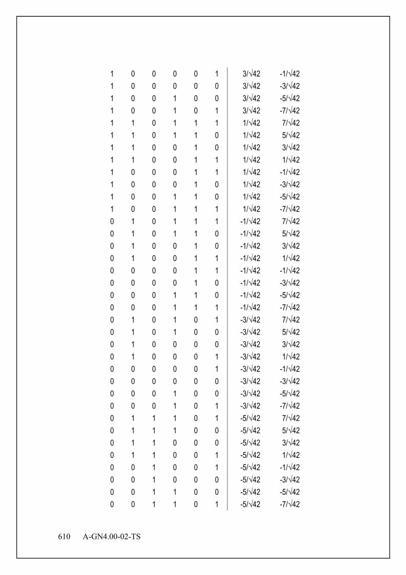
610 A-GN4.00-02-TS
1 0 0 0 0 1 3/√42 -1/√42 1 0 0 0 0 0 3/√42 -3/√42 1 0 0 1 0 0 3/√42 -5/√42 1 0 0 1 0 1 3/√42 -7/√42 1 1 0 1 1 1 1/√42 7/√42 1 1 0 1 1 0 1/√42 5/√42 1 1 0 0 1 0 1/√42 3/√42 1 1 0 0 1 1 1/√42 1/√42 1 0 0 0 1 1 1/√42 -1/√42 1 0 0 0 1 0 1/√42 -3/√42 1 0 0 1 1 0 1/√42 -5/√42 1 0 0 1 1 1 1/√42 -7/√42 0 1 0 1 1 1 -1/√42 7/√42 0 1 0 1 1 0 -1/√42 5/√42 0 1 0 0 1 0 -1/√42 3/√42 0 1 0 0 1 1 -1/√42 1/√42 0 0 0 0 1 1 -1/√42 -1/√42 0 0 0 0 1 0 -1/√42 -3/√42 0 0 0 1 1 0 -1/√42 -5/√42 0 0 0 1 1 1 -1/√42 -7/√42 0 1 0 1 0 1 -3/√42 7/√42 0 1 0 1 0 0 -3/√42 5/√42 0 1 0 0 0 0 -3/√42 3/√42 0 1 0 0 0 1 -3/√42 1/√42 0 0 0 0 0 1 -3/√42 -1/√42 0 0 0 0 0 0 -3/√42 -3/√42 0 0 0 1 0 0 -3/√42 -5/√42 0 0 0 1 0 1 -3/√42 -7/√42 0 1 1 1 0 1 -5/√42 7/√42 0 1 1 1 0 0 -5/√42 5/√42 0 1 1 0 0 0 -5/√42 3/√42 0 1 1 0 0 1 -5/√42 1/√42 0 0 1 0 0 1 -5/√42 -1/√42 0 0 1 0 0 0 -5/√42 -3/√42 0 0 1 1 0 0 -5/√42 -5/√42 0 0 1 1 0 1 -5/√42 -7/√42

A-GN4.00-02-TS 611
0 1 1 1 1 1 -7/√42 7/√42 0 1 1 1 1 0 -7/√42 5/√42 0 1 1 0 1 0 -7/√42 3/√42 0 1 1 0 1 1 -7/√42 1/√42 0 0 1 0 1 1 -7/√42 -1/√42 0 0 1 0 1 0 -7/√42 -3/√42 0 0 1 1 1 0 -7/√42 -5/√42 0 0 1 1 1 1 -7/√42 -7/√42
(2) The signal space diagram is shown in the figure below.
Figure B.7 64QAM
I
Q
111111
111110
111010
111011
101011
101010
101110
101111
111101
111100
111000
111001
101001
101000
101100
101101
110101
110100
110000
110001
100001
100000
100100
100101
110111
110110
110010
110011
100011
100010
100110
100111
010111
010110
010010
010011
000011
000010
000110
000111
010101
010100
010000
010001
000001
000000
000100
000101
011101
011100
011000
011001
001001
001000
001100
001101
011111
011110
011010
011011
001011
001010
001110
001111

612 A-GN4.00-02-TS
B.8 256QAM (1) The serial signal input is converted to (Ak, Bk, Ck, Dk, Ek, Fk, Gk, Hk) symbols by the serial/parallel converter and then changed to corresponding signals (Ik, Qk) by the encoder. Conversion from serial signal input to (Ak, Bk, Ck, Dk, Ek, Fk, Gk, Hk) (binary/256ary conversion) is performed as noted below, and conversion from (Ak, Bk, Ck, Dk, Ek, Fk, Gk, Hk) to (Ik, Qk) is performed according to the table below.
Binary Data Time Series an an+1 an+2 an+6 an+7 ↓ ↓ ↓ ↓ ↓ ↓ ↓
Symbol Time Series (an, an+1, an+2, …, an+6, an+7) ↓ ↓ ↓ ↓ ↓ ↓ Ak Bk Ck … Gk Hk
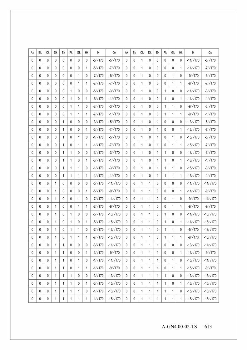
A-GN4.00-02-TS 613
Ak Bk Ck Dk Ek Fk Gk Hk Ik Qk Ak Bk Ck Dk Ek Fk Gk Hk Ik Qk
0 0 0 0 0 0 0 0 -5/√170 -5/√170 0 0 1 0 0 0 0 0 -11/√170 -5/√170
0 0 0 0 0 0 0 1 -5/√170 -7/√170 0 0 1 0 0 0 0 1 -11/√170 -7/√170
0 0 0 0 0 0 1 0 -7/√170 -5/√170 0 0 1 0 0 0 1 0 -9/√170 -5/√170
0 0 0 0 0 0 1 1 -7/√170 -7/√170 0 0 1 0 0 0 1 1 -9/√170 -7/√170
0 0 0 0 0 1 0 0 -5/√170 -3/√170 0 0 1 0 0 1 0 0 -11/√170 -3/√170
0 0 0 0 0 1 0 1 -5/√170 -1/√170 0 0 1 0 0 1 0 1 -11/√170 -1/√170
0 0 0 0 0 1 1 0 -7/√170 -3/√170 0 0 1 0 0 1 1 0 -9/√170 -3/√170
0 0 0 0 0 1 1 1 -7/√170 -1/√170 0 0 1 0 0 1 1 1 -9/√170 -1/√170
0 0 0 0 1 0 0 0 -3/√170 -5/√170 0 0 1 0 1 0 0 0 -13/√170 -5/√170
0 0 0 0 1 0 0 1 -3/√170 -7/√170 0 0 1 0 1 0 0 1 -13/√170 -7/√170
0 0 0 0 1 0 1 0 -1/√170 -5/√170 0 0 1 0 1 0 1 0 -15/√170 -5/√170
0 0 0 0 1 0 1 1 -1/√170 -7/√170 0 0 1 0 1 0 1 1 -15/√170 -7/√170
0 0 0 0 1 1 0 0 -3/√170 -3/√170 0 0 1 0 1 1 0 0 -13/√170 -3/√170
0 0 0 0 1 1 0 1 -3/√170 -1/√170 0 0 1 0 1 1 0 1 -13/√170 -1/√170
0 0 0 0 1 1 1 0 -1/√170 -3/√170 0 0 1 0 1 1 1 0 -15/√170 -3/√170
0 0 0 0 1 1 1 1 -1/√170 -1/√170 0 0 1 0 1 1 1 1 -15/√170 -1/√170
0 0 0 1 0 0 0 0 -5/√170 -11/√170 0 0 1 1 0 0 0 0 -11/√170 -11/√170
0 0 0 1 0 0 0 1 -5/√170 -9/√170 0 0 1 1 0 0 0 1 -11/√170 -9/√170
0 0 0 1 0 0 1 0 -7/√170 -11/√170 0 0 1 1 0 0 1 0 -9/√170 -11/√170
0 0 0 1 0 0 1 1 -7/√170 -9/√170 0 0 1 1 0 0 1 1 -9/√170 -9/√170
0 0 0 1 0 1 0 0 -5/√170 -13/√170 0 0 1 1 0 1 0 0 -11/√170 -13/√170
0 0 0 1 0 1 0 1 -5/√170 -15/√170 0 0 1 1 0 1 0 1 -11/√170 -15/√170
0 0 0 1 0 1 1 0 -7/√170 -13/√170 0 0 1 1 0 1 1 0 -9/√170 -13/√170
0 0 0 1 0 1 1 1 -7/√170 -15/√170 0 0 1 1 0 1 1 1 -9/√170 -15/√170
0 0 0 1 1 0 0 0 -3/√170 -11/√170 0 0 1 1 1 0 0 0 -13/√170 -11/√170
0 0 0 1 1 0 0 1 -3/√170 -9/√170 0 0 1 1 1 0 0 1 -13/√170 -9/√170
0 0 0 1 1 0 1 0 -1/√170 -11/√170 0 0 1 1 1 0 1 0 -15/√170 -11/√170
0 0 0 1 1 0 1 1 -1/√170 -9/√170 0 0 1 1 1 0 1 1 -15/√170 -9/√170
0 0 0 1 1 1 0 0 -3/√170 -13/√170 0 0 1 1 1 1 0 0 -13/√170 -13/√170
0 0 0 1 1 1 0 1 -3/√170 -15/√170 0 0 1 1 1 1 0 1 -13/√170 -15/√170
0 0 0 1 1 1 1 0 -1/√170 -13/√170 0 0 1 1 1 1 1 0 -15/√170 -13/√170
0 0 0 1 1 1 1 1 -1/√170 -15/√170 0 0 1 1 1 1 1 1 -15/√170 -15/√170

614 A-GN4.00-02-TS
Ak Bk Ck Dk Ek Fk Gk Hk Ik Qk Ak Bk Ck Dk Ek Fk Gk Hk Ik Qk
0 1 0 0 0 0 0 0 -5/√170 5/√170 0 1 1 0 0 0 0 0 -11/√170 5/√170
0 1 0 0 0 0 0 1 -5/√170 7/√170 0 1 1 0 0 0 0 1 -11/√170 7/√170
0 1 0 0 0 0 1 0 -7/√170 5/√170 0 1 1 0 0 0 1 0 -9/√170 5/√170
0 1 0 0 0 0 1 1 -7/√170 7/√170 0 1 1 0 0 0 1 1 -9/√170 7/√170
0 1 0 0 0 1 0 0 -5/√170 3/√170 0 1 1 0 0 1 0 0 -11/√170 3/√170
0 1 0 0 0 1 0 1 -5/√170 1/√170 0 1 1 0 0 1 0 1 -11/√170 1/√170
0 1 0 0 0 1 1 0 -7/√170 3/√170 0 1 1 0 0 1 1 0 -9/√170 3/√170
0 1 0 0 0 1 1 1 -7/√170 1/√170 0 1 1 0 0 1 1 1 -9/√170 1/√170
0 1 0 0 1 0 0 0 -3/√170 5/√170 0 1 1 0 1 0 0 0 -13/√170 5/√170
0 1 0 0 1 0 0 1 -3/√170 7/√170 0 1 1 0 1 0 0 1 -13/√170 7/√170
0 1 0 0 1 0 1 0 -1/√170 5/√170 0 1 1 0 1 0 1 0 -15/√170 5/√170
0 1 0 0 1 0 1 1 -1/√170 7/√170 0 1 1 0 1 0 1 1 -15/√170 7/√170
0 1 0 0 1 1 0 0 -3/√170 3/√170 0 1 1 0 1 1 0 0 -13/√170 3/√170
0 1 0 0 1 1 0 1 -3/√170 1/√170 0 1 1 0 1 1 0 1 -13/√170 1/√170
0 1 0 0 1 1 1 0 -1/√170 3/√170 0 1 1 0 1 1 1 0 -15/√170 3/√170
0 1 0 0 1 1 1 1 -1/√170 1/√170 0 1 1 0 1 1 1 1 -15/√170 1/√170
0 1 0 1 0 0 0 0 -5/√170 11/√170 0 1 1 1 0 0 0 0 -11/√170 11/√170
0 1 0 1 0 0 0 1 -5/√170 9/√170 0 1 1 1 0 0 0 1 -11/√170 9/√170
0 1 0 1 0 0 1 0 -7/√170 11/√170 0 1 1 1 0 0 1 0 -9/√170 11/√170
0 1 0 1 0 0 1 1 -7/√170 9/√170 0 1 1 1 0 0 1 1 -9/√170 9/√170
0 1 0 1 0 1 0 0 -5/√170 13/√170 0 1 1 1 0 1 0 0 -11/√170 13/√170
0 1 0 1 0 1 0 1 -5/√170 15/√170 0 1 1 1 0 1 0 1 -11/√170 15/√170
0 1 0 1 0 1 1 0 -7/√170 13/√170 0 1 1 1 0 1 1 0 -9/√170 13/√170
0 1 0 1 0 1 1 1 -7/√170 15/√170 0 1 1 1 0 1 1 1 -9/√170 15/√170
0 1 0 1 1 0 0 0 -3/√170 11/√170 0 1 1 1 1 0 0 0 -13/√170 11/√170
0 1 0 1 1 0 0 1 -3/√170 9/√170 0 1 1 1 1 0 0 1 -13/√170 9/√170
0 1 0 1 1 0 1 0 -1/√170 11/√170 0 1 1 1 1 0 1 0 -15/√170 11/√170
0 1 0 1 1 0 1 1 -1/√170 9/√170 0 1 1 1 1 0 1 1 -15/√170 9/√170
0 1 0 1 1 1 0 0 -3/√170 13/√170 0 1 1 1 1 1 0 0 -13/√170 13/√170
0 1 0 1 1 1 0 1 -3/√170 15/√170 0 1 1 1 1 1 0 1 -13/√170 15/√170
0 1 0 1 1 1 1 0 -1/√170 13/√170 0 1 1 1 1 1 1 0 -15/√170 13/√170
0 1 0 1 1 1 1 1 -1/√170 15/√170 0 1 1 1 1 1 1 1 -15/√170 15/√170

A-GN4.00-02-TS 615
Ak Bk Ck Dk Ek Fk Gk Hk Ik Qk Ak Bk Ck Dk Ek Fk Gk Hk Ik Qk
1 0 0 0 0 0 0 0 5/√170 -5/√170 1 0 1 0 0 0 0 0 11/√170 -5/√170
1 0 0 0 0 0 0 1 5/√170 -7/√170 1 0 1 0 0 0 0 1 11/√170 -7/√170
1 0 0 0 0 0 1 0 7/√170 -5/√170 1 0 1 0 0 0 1 0 9/√170 -5/√170
1 0 0 0 0 0 1 1 7/√170 -7/√170 1 0 1 0 0 0 1 1 9/√170 -7/√170
1 0 0 0 0 1 0 0 5/√170 -3/√170 1 0 1 0 0 1 0 0 11/√170 -3/√170
1 0 0 0 0 1 0 1 5/√170 -1/√170 1 0 1 0 0 1 0 1 11/√170 -1/√170
1 0 0 0 0 1 1 0 7/√170 -3/√170 1 0 1 0 0 1 1 0 9/√170 -3/√170
1 0 0 0 0 1 1 1 7/√170 -1/√170 1 0 1 0 0 1 1 1 9/√170 -1/√170
1 0 0 0 1 0 0 0 3/√170 -5/√170 1 0 1 0 1 0 0 0 13/√170 -5/√170
1 0 0 0 1 0 0 1 3/√170 -7/√170 1 0 1 0 1 0 0 1 13/√170 -7/√170
1 0 0 0 1 0 1 0 1/√170 -5/√170 1 0 1 0 1 0 1 0 15/√170 -5/√170
1 0 0 0 1 0 1 1 1/√170 -7/√170 1 0 1 0 1 0 1 1 15/√170 -7/√170
1 0 0 0 1 1 0 0 3/√170 -3/√170 1 0 1 0 1 1 0 0 13/√170 -3/√170
1 0 0 0 1 1 0 1 3/√170 -1/√170 1 0 1 0 1 1 0 1 13/√170 -1/√170
1 0 0 0 1 1 1 0 1/√170 -3/√170 1 0 1 0 1 1 1 0 15/√170 -3/√170
1 0 0 0 1 1 1 1 1/√170 -1/√170 1 0 1 0 1 1 1 1 15/√170 -1/√170
1 0 0 1 0 0 0 0 5/√170 -11/√170 1 0 1 1 0 0 0 0 11/√170 -11/√170
1 0 0 1 0 0 0 1 5/√170 -9/√170 1 0 1 1 0 0 0 1 11/√170 -9/√170
1 0 0 1 0 0 1 0 7/√170 -11/√170 1 0 1 1 0 0 1 0 9/√170 -11/√170
1 0 0 1 0 0 1 1 7/√170 -9/√170 1 0 1 1 0 0 1 1 9/√170 -9/√170
1 0 0 1 0 1 0 0 5/√170 -13/√170 1 0 1 1 0 1 0 0 11/√170 -13/√170
1 0 0 1 0 1 0 1 5/√170 -15/√170 1 0 1 1 0 1 0 1 11/√170 -15/√170
1 0 0 1 0 1 1 0 7/√170 -13/√170 1 0 1 1 0 1 1 0 9/√170 -13/√170
1 0 0 1 0 1 1 1 7/√170 -15/√170 1 0 1 1 0 1 1 1 9/√170 -15/√170
1 0 0 1 1 0 0 0 3/√170 -11/√170 1 0 1 1 1 0 0 0 13/√170 -11/√170
1 0 0 1 1 0 0 1 3/√170 -9/√170 1 0 1 1 1 0 0 1 13/√170 -9/√170
1 0 0 1 1 0 1 0 1/√170 -11/√170 1 0 1 1 1 0 1 0 15/√170 -11/√170
1 0 0 1 1 0 1 1 1/√170 -9/√170 1 0 1 1 1 0 1 1 15/√170 -9/√170
1 0 0 1 1 1 0 0 3/√170 -13/√170 1 0 1 1 1 1 0 0 13/√170 -13/√170
1 0 0 1 1 1 0 1 3/√170 -15/√170 1 0 1 1 1 1 0 1 13/√170 -15/√170
1 0 0 1 1 1 1 0 1/√170 -13/√170 1 0 1 1 1 1 1 0 15/√170 -13/√170
1 0 0 1 1 1 1 1 1/√170 -15/√170 1 0 1 1 1 1 1 1 15/√170 -15/√170
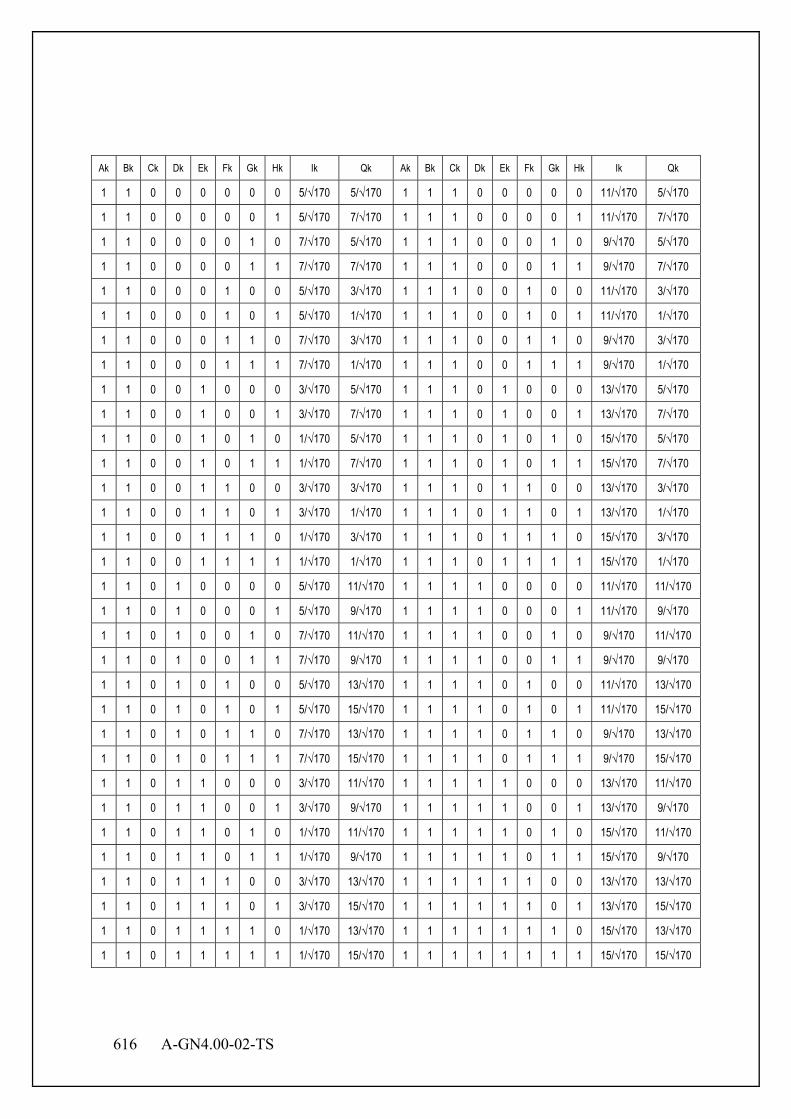
616 A-GN4.00-02-TS
Ak Bk Ck Dk Ek Fk Gk Hk Ik Qk Ak Bk Ck Dk Ek Fk Gk Hk Ik Qk
1 1 0 0 0 0 0 0 5/√170 5/√170 1 1 1 0 0 0 0 0 11/√170 5/√170
1 1 0 0 0 0 0 1 5/√170 7/√170 1 1 1 0 0 0 0 1 11/√170 7/√170
1 1 0 0 0 0 1 0 7/√170 5/√170 1 1 1 0 0 0 1 0 9/√170 5/√170
1 1 0 0 0 0 1 1 7/√170 7/√170 1 1 1 0 0 0 1 1 9/√170 7/√170
1 1 0 0 0 1 0 0 5/√170 3/√170 1 1 1 0 0 1 0 0 11/√170 3/√170
1 1 0 0 0 1 0 1 5/√170 1/√170 1 1 1 0 0 1 0 1 11/√170 1/√170
1 1 0 0 0 1 1 0 7/√170 3/√170 1 1 1 0 0 1 1 0 9/√170 3/√170
1 1 0 0 0 1 1 1 7/√170 1/√170 1 1 1 0 0 1 1 1 9/√170 1/√170
1 1 0 0 1 0 0 0 3/√170 5/√170 1 1 1 0 1 0 0 0 13/√170 5/√170
1 1 0 0 1 0 0 1 3/√170 7/√170 1 1 1 0 1 0 0 1 13/√170 7/√170
1 1 0 0 1 0 1 0 1/√170 5/√170 1 1 1 0 1 0 1 0 15/√170 5/√170
1 1 0 0 1 0 1 1 1/√170 7/√170 1 1 1 0 1 0 1 1 15/√170 7/√170
1 1 0 0 1 1 0 0 3/√170 3/√170 1 1 1 0 1 1 0 0 13/√170 3/√170
1 1 0 0 1 1 0 1 3/√170 1/√170 1 1 1 0 1 1 0 1 13/√170 1/√170
1 1 0 0 1 1 1 0 1/√170 3/√170 1 1 1 0 1 1 1 0 15/√170 3/√170
1 1 0 0 1 1 1 1 1/√170 1/√170 1 1 1 0 1 1 1 1 15/√170 1/√170
1 1 0 1 0 0 0 0 5/√170 11/√170 1 1 1 1 0 0 0 0 11/√170 11/√170
1 1 0 1 0 0 0 1 5/√170 9/√170 1 1 1 1 0 0 0 1 11/√170 9/√170
1 1 0 1 0 0 1 0 7/√170 11/√170 1 1 1 1 0 0 1 0 9/√170 11/√170
1 1 0 1 0 0 1 1 7/√170 9/√170 1 1 1 1 0 0 1 1 9/√170 9/√170
1 1 0 1 0 1 0 0 5/√170 13/√170 1 1 1 1 0 1 0 0 11/√170 13/√170
1 1 0 1 0 1 0 1 5/√170 15/√170 1 1 1 1 0 1 0 1 11/√170 15/√170
1 1 0 1 0 1 1 0 7/√170 13/√170 1 1 1 1 0 1 1 0 9/√170 13/√170
1 1 0 1 0 1 1 1 7/√170 15/√170 1 1 1 1 0 1 1 1 9/√170 15/√170
1 1 0 1 1 0 0 0 3/√170 11/√170 1 1 1 1 1 0 0 0 13/√170 11/√170
1 1 0 1 1 0 0 1 3/√170 9/√170 1 1 1 1 1 0 0 1 13/√170 9/√170
1 1 0 1 1 0 1 0 1/√170 11/√170 1 1 1 1 1 0 1 0 15/√170 11/√170
1 1 0 1 1 0 1 1 1/√170 9/√170 1 1 1 1 1 0 1 1 15/√170 9/√170
1 1 0 1 1 1 0 0 3/√170 13/√170 1 1 1 1 1 1 0 0 13/√170 13/√170
1 1 0 1 1 1 0 1 3/√170 15/√170 1 1 1 1 1 1 0 1 13/√170 15/√170
1 1 0 1 1 1 1 0 1/√170 13/√170 1 1 1 1 1 1 1 0 15/√170 13/√170
1 1 0 1 1 1 1 1 1/√170 15/√170 1 1 1 1 1 1 1 1 15/√170 15/√170

A-GN4.00-02-TS 617
(2) The signal space diagram is shown in figure below.
Figure B.8 256QAM
11111101 11111111
11111100 11111110
11110111 11110101
11110110 11110100
11010101 11010111
11010100 11010110
11011111 11011101
11011110 11011100
11111000 1111101011110010 1111000011010000 1101001011011010 11011000
11111001 1111101111110011 1111000111010001 1101001111011011 11011001
11101001 1110101111100011 1110000111000001 1100001111001011 11001001
11101000 1110101011100010 1110000011000000 1100001011001010 11001000
11101100 1110111011100110 1110010011000100 1100011011001110 11001100
11101101 1110111111100111 1110010111000101 1100011111001111 11001101
10101101 1010111110100111 1010010110000101 1000011110001111 10001101
10101100 1010111010100110 1010010010000100 1000011010001110 10001100
10101000 1010101010100010 1010000010000000 1000001010001010 10001000
10101001 1010101110100011 1010000110000001 1000001110001011 10001001
10111101 10111111
10111100 10111110
10110111 10110101
10110110 10110100
10010101 10010111
10010100 10010110
10011111 10011101
10011110 10011100
10111000 1011101010110010 1011000010010000 1001001010011010 10011000
10111001 1011101110110011 1011000110010001 1001001110011011 10011001
00001111
00001110
00001010
00001011
00011111
00011110
00011010
00011011
00001101
00001100
00001000
00001001
00011101
00011100
00011000
00011001
00000101
00000100
00000000
00000001
00010101
00010100
00010000
00010001
00000111
00000110
00000010
00000011
00010111
00010110
00010010
00010011
00100111
00100110
00100010
00100011
00110111
00110110
00110010
00110011
00100101
00100100
00100000
00100001
00110101
00110100
00110000
00110001
00101101
00101100
00101000
00101001
00111101
00111100
00111000
00111001
00101111
00101110
00101010
00101011
00111111
00111110
00111010
00111011
0100111101001101010001010100011101100111011001010110110101101111
0100111001001100010001000100011001100110011001000110110001101110
0100101001001000010000000100001001100010011000000110100001101010
0100101101001001010000010100001101100011011000010110100101101011
01011111
01011110
01011010
01011011
01011101
01011100
01011000
01011001
01010101
01010100
01010000
01010001
01010111
01010110
01010010
01010011
01110111
01110110
01110010
01110011
01110101
01110100
01110000
01110001
01111101
01111100
01111000
01111001
01111111
01111110
01111010
01111011
I
Q

618 A-GN4.00-02-TS
B.9 16PSK The signal space diagram for 16PSK is shown in Figure B.9. 16PSK is only used for training sequences for SC.
Ak Ik Qk a 1 0 b 0.923879533 0.382683432 c 0.707106781 0.707106781 d 0.382683432 0.923879533 e 0 1 f -0.382683432 0.923879533 g -0.707106781 0.707106781 h -0.923879533 0.382683432 i -1 0 j -0.923879533 -0.382683432 k -0.707106781 -0.707106781 l -0.382683432 -0.923879533
m 0 -1 n 0.382683432 -0.923879533 o 0.707106781 -0.707106781 p 0.923879533 -0.382683432
Figure B.9 16PSK
I
Q
m
e
i
g c
a
o k
b
d f
h
j
l n
p
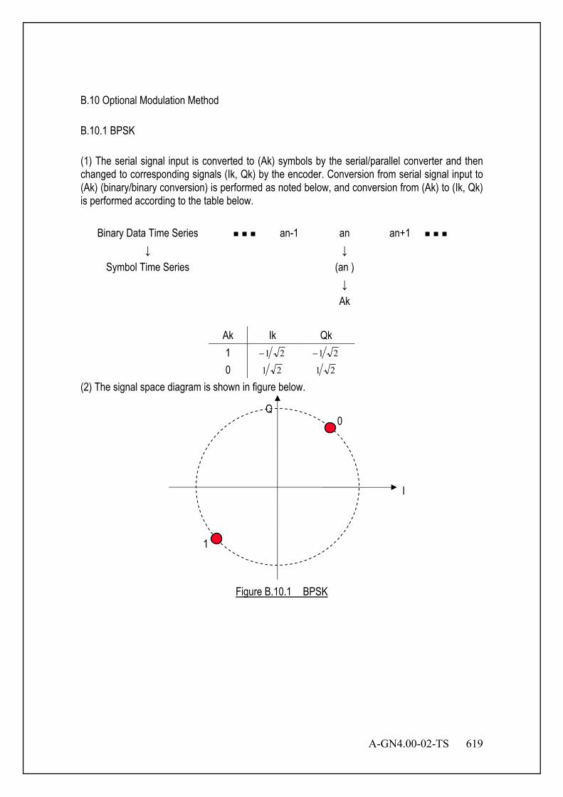
A-GN4.00-02-TS 619
B.10 Optional Modulation Method B.10.1 BPSK (1) The serial signal input is converted to (Ak) symbols by the serial/parallel converter and then changed to corresponding signals (Ik, Qk) by the encoder. Conversion from serial signal input to (Ak) (binary/binary conversion) is performed as noted below, and conversion from (Ak) to (Ik, Qk) is performed according to the table below.
Binary Data Time Series an-1 an an+1 ↓ ↓
Symbol Time Series (an ) ↓ Ak
Ak Ik Qk 1 21− 21−
0 21 21
(2) The signal space diagram is shown in figure below.
Figure B.10.1 BPSK
I
Q
1
0
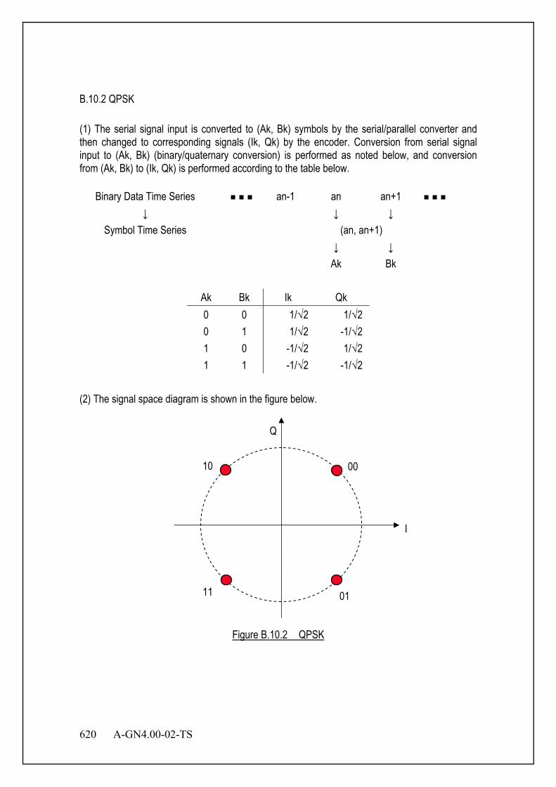
620 A-GN4.00-02-TS
B.10.2 QPSK (1) The serial signal input is converted to (Ak, Bk) symbols by the serial/parallel converter and then changed to corresponding signals (Ik, Qk) by the encoder. Conversion from serial signal input to (Ak, Bk) (binary/quaternary conversion) is performed as noted below, and conversion from (Ak, Bk) to (Ik, Qk) is performed according to the table below.
Binary Data Time Series an-1 an an+1 ↓ ↓ ↓
Symbol Time Series (an, an+1) ↓ ↓ Ak Bk
Ak Bk Ik Qk 0 0 1/√2 1/√2 0 1 1/√2 -1/√2 1 0 -1/√2 1/√2 1 1 -1/√2 -1/√2
(2) The signal space diagram is shown in the figure below.
Figure B.10.2 QPSK
I
Q
11 01
00 10

A-GN4.00-02-TS 621
B.10.3 16QAM (1) The serial signal input is converted to (Ak, Bk, Ck, Dk) symbols by the serial/parallel
converter and then changed to corresponding signals (Ik, Qk) by the encoder. Conversion from serial signal input to (Ak, Bk, Ck, Dk) (binary/16ary conversion) is performed as noted below, and conversion from (Ak, Bk, Ck, Dk) to (Ik, Qk) is performed according to the table below.
Binary Data Time Series an-1 an an+1 an+2 an+3
↓ ↓ ↓ ↓ ↓ Symbol Time Series (an, an+1, an+2, an+3)
↓ ↓ ↓ ↓ Ak Bk Ck Dk
Ak Bk Ck Dk Ik Qk 0 0 0 0 101 101
0 0 0 1 101 103
0 0 1 0 103 101
0 0 1 1 103 103
0 1 0 0 101 101−
0 1 0 1 101 103−
0 1 1 0 103 101−
0 1 1 1 103 103−
1 0 0 0 101− 101
1 0 0 1 101− 103
1 0 1 0 103− 101
1 0 1 1 103− 103
1 1 0 0 101− 101−
1 1 0 1 101− 103−
1 1 1 0 103− 101−
1 1 1 1 103− 103−
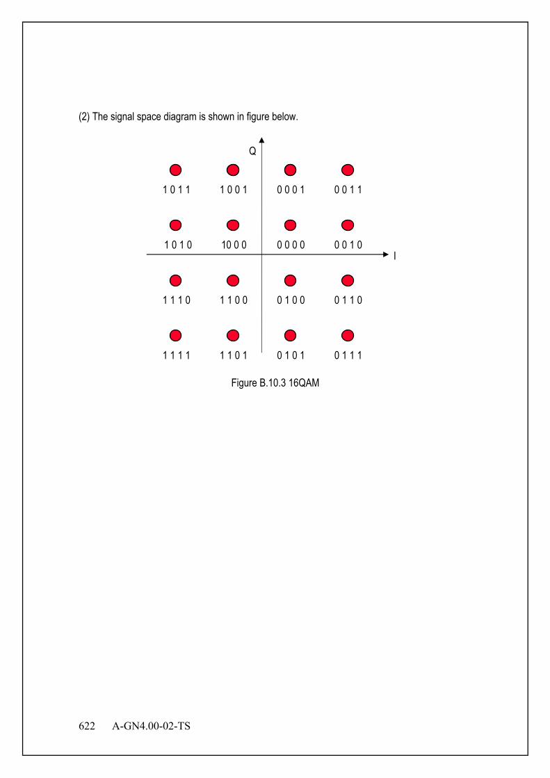
622 A-GN4.00-02-TS
(2) The signal space diagram is shown in figure below.
Figure B.10.3 16QAM
I
Q
1 1 0 0
0 1 0 1 0 1 1 1
1 1 1 0
1 1 0 1
0 1 0 0 0 1 1 0
1 1 1 1
1 0 0 1
0 0 0 0 0 0 1 0
1 0 1 1
10 0 0
0 0 0 1 0 0 1 1
1 0 1 0
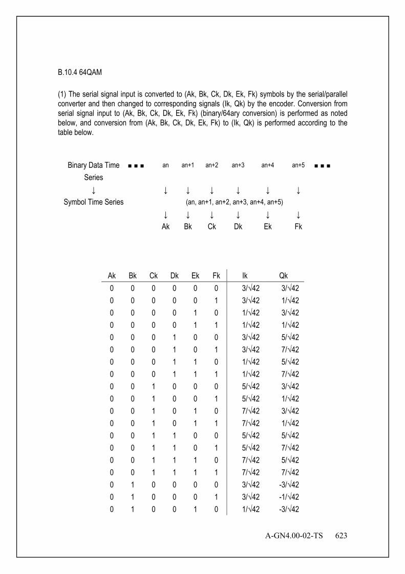
A-GN4.00-02-TS 623
B.10.4 64QAM (1) The serial signal input is converted to (Ak, Bk, Ck, Dk, Ek, Fk) symbols by the serial/parallel converter and then changed to corresponding signals (Ik, Qk) by the encoder. Conversion from serial signal input to (Ak, Bk, Ck, Dk, Ek, Fk) (binary/64ary conversion) is performed as noted below, and conversion from (Ak, Bk, Ck, Dk, Ek, Fk) to (Ik, Qk) is performed according to the table below.
Binary Data Time Series
an an+1 an+2 an+3 an+4 an+5
↓ ↓ ↓ ↓ ↓ ↓ ↓ Symbol Time Series (an, an+1, an+2, an+3, an+4, an+5) ↓ ↓ ↓ ↓ ↓ ↓ Ak Bk Ck Dk Ek Fk
Ak Bk Ck Dk Ek Fk Ik Qk 0 0 0 0 0 0 3/√42 3/√42 0 0 0 0 0 1 3/√42 1/√42 0 0 0 0 1 0 1/√42 3/√42 0 0 0 0 1 1 1/√42 1/√42 0 0 0 1 0 0 3/√42 5/√42 0 0 0 1 0 1 3/√42 7/√42 0 0 0 1 1 0 1/√42 5/√42 0 0 0 1 1 1 1/√42 7/√42 0 0 1 0 0 0 5/√42 3/√42 0 0 1 0 0 1 5/√42 1/√42 0 0 1 0 1 0 7/√42 3/√42 0 0 1 0 1 1 7/√42 1/√42 0 0 1 1 0 0 5/√42 5/√42 0 0 1 1 0 1 5/√42 7/√42 0 0 1 1 1 0 7/√42 5/√42 0 0 1 1 1 1 7/√42 7/√42 0 1 0 0 0 0 3/√42 -3/√42 0 1 0 0 0 1 3/√42 -1/√42 0 1 0 0 1 0 1/√42 -3/√42
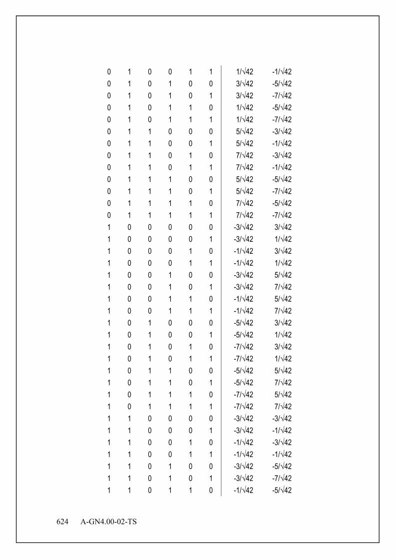
624 A-GN4.00-02-TS
0 1 0 0 1 1 1/√42 -1/√42 0 1 0 1 0 0 3/√42 -5/√42 0 1 0 1 0 1 3/√42 -7/√42 0 1 0 1 1 0 1/√42 -5/√42 0 1 0 1 1 1 1/√42 -7/√42 0 1 1 0 0 0 5/√42 -3/√42 0 1 1 0 0 1 5/√42 -1/√42 0 1 1 0 1 0 7/√42 -3/√42 0 1 1 0 1 1 7/√42 -1/√42 0 1 1 1 0 0 5/√42 -5/√42 0 1 1 1 0 1 5/√42 -7/√42 0 1 1 1 1 0 7/√42 -5/√42 0 1 1 1 1 1 7/√42 -7/√42 1 0 0 0 0 0 -3/√42 3/√42 1 0 0 0 0 1 -3/√42 1/√42 1 0 0 0 1 0 -1/√42 3/√42 1 0 0 0 1 1 -1/√42 1/√42 1 0 0 1 0 0 -3/√42 5/√42 1 0 0 1 0 1 -3/√42 7/√42 1 0 0 1 1 0 -1/√42 5/√42 1 0 0 1 1 1 -1/√42 7/√42 1 0 1 0 0 0 -5/√42 3/√42 1 0 1 0 0 1 -5/√42 1/√42 1 0 1 0 1 0 -7/√42 3/√42 1 0 1 0 1 1 -7/√42 1/√42 1 0 1 1 0 0 -5/√42 5/√42 1 0 1 1 0 1 -5/√42 7/√42 1 0 1 1 1 0 -7/√42 5/√42 1 0 1 1 1 1 -7/√42 7/√42 1 1 0 0 0 0 -3/√42 -3/√42 1 1 0 0 0 1 -3/√42 -1/√42 1 1 0 0 1 0 -1/√42 -3/√42 1 1 0 0 1 1 -1/√42 -1/√42 1 1 0 1 0 0 -3/√42 -5/√42 1 1 0 1 0 1 -3/√42 -7/√42 1 1 0 1 1 0 -1/√42 -5/√42

A-GN4.00-02-TS 625
1 1 0 1 1 1 -1/√42 -7/√42 1 1 1 0 0 0 -5/√42 -3/√42 1 1 1 0 0 1 -5/√42 -1/√42 1 1 1 0 1 0 -7/√42 -3/√42 1 1 1 0 1 1 -7/√42 -1/√42 1 1 1 1 0 0 -5/√42 -5/√42 1 1 1 1 0 1 -5/√42 -7/√42 1 1 1 1 1 0 -7/√42 -5/√42 1 1 1 1 1 1 -7/√42 -7/√42
(2) The signal space diagram is shown in the figure below.
Figure B.10.4 64QAM
I
Q
001111
001110
001010
001011
011011
011010
011110
011111
001101
001100
001000
001001
011001
011000
011100
011101
000101
000100
000000
000001
010001
010000
010100
010101
000111
000110
000010
000011
010011
010010
010110
010111
100111
100110
100010
100011
110011
110010
110110
110111
100101
100100
100000
100001
110001
110000
110100
110101
101101
101100
101000
101001
111001
111000
111100
111101
101111
101110
101010
101011
111011
111010
111110
111111
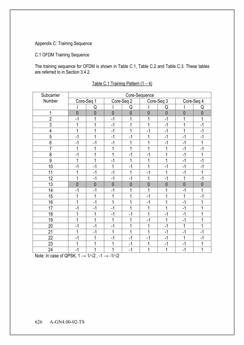
626 A-GN4.00-02-TS
Appendix C: Training Sequence C.1 OFDM Training Sequence The training sequence for OFDM is shown in Table C.1, Table C.2 and Table C.3. These tables are referred to in Section 3.4.2.
Table C.1 Training Pattern (1 – 4)
Subcarrier Number
Core-Sequence Core-Seq 1 Core-Seq 2 Core-Seq 3 Core-Seq 4 I Q I Q I Q I Q
1 0 0 0 0 0 0 0 0 2 -1 1 -1 1 1 -1 1 1 3 1 1 -1 1 1 -1 1 -1 4 1 1 -1 1 -1 -1 1 -1 5 -1 1 -1 -1 1 -1 -1 -1 6 -1 -1 -1 1 1 -1 -1 1 7 1 1 1 1 1 1 -1 -1 8 -1 1 1 -1 -1 1 -1 1 9 1 1 -1 1 1 1 -1 -1 10 -1 -1 1 -1 1 -1 -1 -1 11 1 -1 -1 1 -1 1 -1 1 12 1 -1 -1 -1 1 -1 1 -1 13 0 0 0 0 0 0 0 0 14 -1 -1 -1 1 1 1 -1 1 15 1 1 1 1 -1 1 1 -1 16 1 -1 1 1 -1 1 -1 1 17 -1 -1 -1 1 1 1 -1 1 18 1 1 -1 -1 1 -1 -1 1 19 1 1 1 1 -1 1 -1 1 20 -1 -1 -1 1 1 -1 1 1 21 1 -1 1 1 1 -1 -1 -1 22 -1 1 -1 -1 -1 -1 1 -1 23 1 1 1 -1 1 -1 -1 1 24 -1 1 1 -1 1 1 -1 1
Note: In case of QPSK, 1 → 1/√2 , -1 → -1/√2
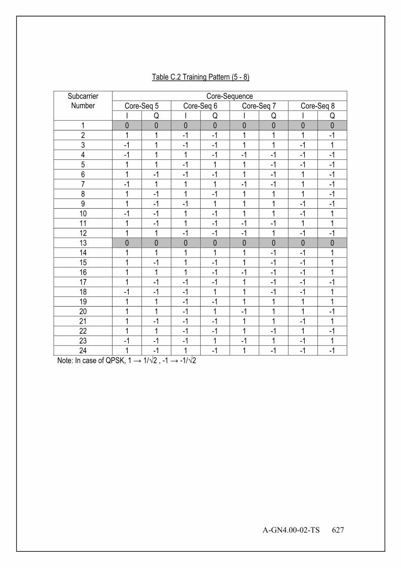
A-GN4.00-02-TS 627
Table C.2 Training Pattern (5 - 8)
Subcarrier Number
Core-Sequence Core-Seq 5 Core-Seq 6 Core-Seq 7 Core-Seq 8 I Q I Q I Q I Q
1 0 0 0 0 0 0 0 0 2 1 1 -1 -1 1 1 1 -1 3 -1 1 -1 -1 1 1 -1 1 4 -1 1 1 -1 -1 -1 -1 -1 5 1 1 -1 1 1 -1 -1 -1 6 1 -1 -1 -1 1 -1 1 -1 7 -1 1 1 1 -1 -1 1 -1 8 1 -1 1 -1 1 1 1 -1 9 1 -1 -1 1 1 1 -1 -1 10 -1 -1 1 -1 1 1 -1 1 11 1 -1 1 -1 -1 -1 1 1 12 1 1 -1 -1 -1 1 -1 -1 13 0 0 0 0 0 0 0 0 14 1 1 1 1 1 -1 -1 1 15 1 -1 1 -1 1 -1 -1 1 16 1 1 1 -1 -1 -1 -1 1 17 1 -1 -1 -1 1 -1 -1 -1 18 -1 -1 -1 1 1 -1 -1 1 19 1 1 -1 -1 1 1 1 1 20 1 1 -1 1 -1 1 1 -1 21 1 -1 -1 -1 1 1 -1 1 22 1 1 -1 -1 1 -1 1 -1 23 -1 -1 -1 1 -1 1 -1 1 24 1 -1 1 -1 1 -1 -1 -1
Note: In case of QPSK, 1 → 1/√2 , -1 → -1/√2
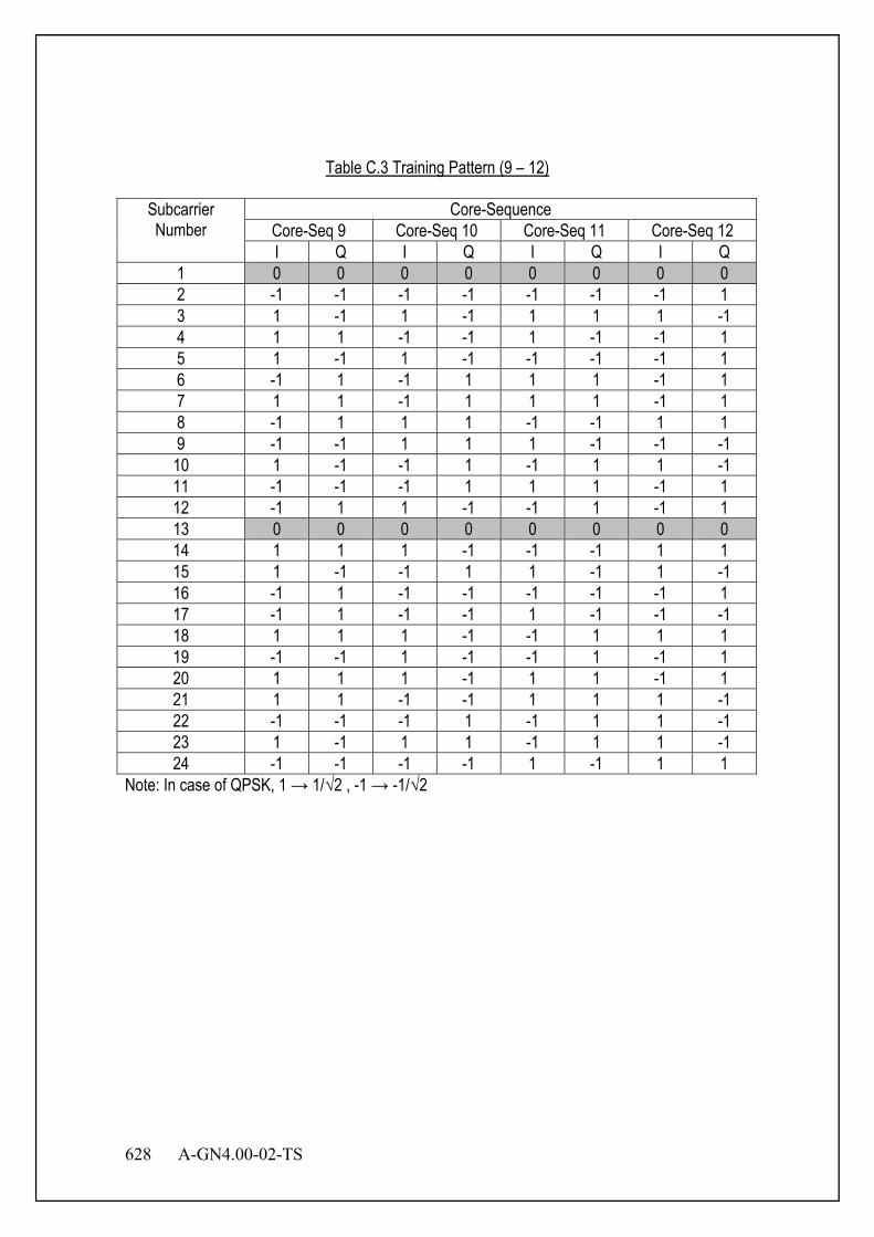
628 A-GN4.00-02-TS
Table C.3 Training Pattern (9 – 12)
Subcarrier Number
Core-Sequence Core-Seq 9 Core-Seq 10 Core-Seq 11 Core-Seq 12 I Q I Q I Q I Q
1 0 0 0 0 0 0 0 0 2 -1 -1 -1 -1 -1 -1 -1 1 3 1 -1 1 -1 1 1 1 -1 4 1 1 -1 -1 1 -1 -1 1 5 1 -1 1 -1 -1 -1 -1 1 6 -1 1 -1 1 1 1 -1 1 7 1 1 -1 1 1 1 -1 1 8 -1 1 1 1 -1 -1 1 1 9 -1 -1 1 1 1 -1 -1 -1 10 1 -1 -1 1 -1 1 1 -1 11 -1 -1 -1 1 1 1 -1 1 12 -1 1 1 -1 -1 1 -1 1 13 0 0 0 0 0 0 0 0 14 1 1 1 -1 -1 -1 1 1 15 1 -1 -1 1 1 -1 1 -1 16 -1 1 -1 -1 -1 -1 -1 1 17 -1 1 -1 -1 1 -1 -1 -1 18 1 1 1 -1 -1 1 1 1 19 -1 -1 1 -1 -1 1 -1 1 20 1 1 1 -1 1 1 -1 1 21 1 1 -1 -1 1 1 1 -1 22 -1 -1 -1 1 -1 1 1 -1 23 1 -1 1 1 -1 1 1 -1 24 -1 -1 -1 -1 1 -1 1 1
Note: In case of QPSK, 1 → 1/√2 , -1 → -1/√2

A-GN4.00-02-TS 629
Offset value for OFDM training sequence is shown in Table C.4. This table is referred to in Section 3.4.2.
Table C.4 Offset Value for OFDM Training Sequence
System Bandwidth [MHz] 2.5 5 10 20 FFT Size 64 128 256 512
Offset Value 1(X sample) 0 0 0 0 Offset Value 2(X sample) 32 64 128 256 Offset Value 3(X sample) 32 64 128 Offset Value 4(X sample) 96 192 384 Offset Value 5(X sample) 32 64 Offset Value 6(X sample) 96 192 Offset Value 7(X sample) 160 320 Offset Value 8(X sample) 224 448 Offset Value 9(X sample) 16 32 Offset Value 10(X sample) 48 96 Offset Value 11(X sample) 160 Offset Value 12(X sample) 224 Offset Value 13(X sample) 288 Offset Value 14(X sample) 352 Offset Value 15(X sample) 416 Offset Value 16(X sample) 480 Offset Value 17(X sample) 16 Offset Value 18(X sample) 48 Offset Value 19(X sample) 80 Offset Value 20(X sample) 112 Training signals of the offset value are calculated by following equation. θ=2π x (SubcarrierNumber[1 to 24]-13) x Offsetvalue/FFTsize (I,Q)=(ICore-Seq,QCore-Seq)*(cosθ,sinθ) For example, Table C.5 shows the calculated results when core-sequence number is 1 and FFT size is 512 and offset sample is 128.
(C.1)
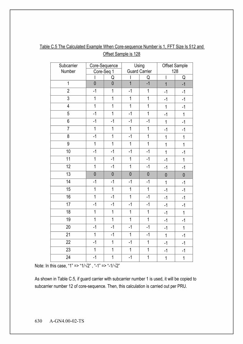
630 A-GN4.00-02-TS
Table C.5 The Calculated Example When Core-sequence Number is 1, FFT Size Is 512 and Offset Sample is 128
Subcarrier Number
Core-Sequence Using Guard Carrier
Offset Sample 128 Core-Seq 1
I Q I Q I Q 1 0 0 1 -1 1 -1 2 -1 1 -1 1 -1 -1 3 1 1 1 1 -1 -1 4 1 1 1 1 1 -1 5 -1 1 -1 1 -1 1 6 -1 -1 -1 -1 1 -1 7 1 1 1 1 -1 -1 8 -1 1 -1 1 1 1 9 1 1 1 1 1 1 10 -1 -1 -1 -1 1 -1 11 1 -1 1 -1 -1 1 12 1 -1 1 -1 -1 -1 13 0 0 0 0 0 0 14 -1 -1 -1 -1 1 -1 15 1 1 1 1 -1 -1 16 1 -1 1 -1 -1 -1 17 -1 -1 -1 -1 -1 -1 18 1 1 1 1 -1 1 19 1 1 1 1 -1 -1 20 -1 -1 -1 -1 -1 1 21 1 -1 1 -1 1 -1 22 -1 1 -1 1 -1 -1 23 1 1 1 1 -1 -1 24 -1 1 -1 1 1 1
Note: In this case, “1” => “1/√2” , “-1” => “-1/√2” As shown in Table C.5, if guard carrier with subcarrier number 1 is used, it will be copied to subcarrier number 12 of core-sequence. Then, this calculation is carried out per PRU.
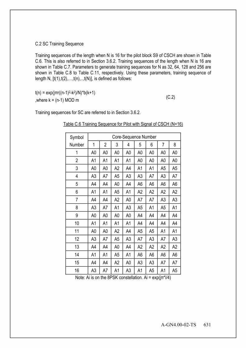
A-GN4.00-02-TS 631
C.2 SC Training Sequence Training sequences of the length when N is 16 for the pilot block S9 of CSCH are shown in Table C.6. This is also referred to in Section 3.6.2. Training sequences of the length when N is 16 are shown in Table C.7. Parameters to generate training sequences for N as 32, 64, 128 and 256 are shown in Table C.8 to Table C.11, respectively. Using these parameters, training sequence of length N, [t(1),t(2),…,t(n),..,t(N)], is defined as follows: t(n) = exp(jπr((n-1)2-k2)/N)*b(k+1) ,where k = (n-1) MOD m Training sequences for SC are referred to in Section 3.6.2.
Table C.6 Training Sequence for Pilot with Signal of CSCH (N=16)
Symbol Number
Core-Sequence Number 1 2 3 4 5 6 7 8
1 A0 A0 A0 A0 A0 A0 A0 A0 2 A1 A1 A1 A1 A0 A0 A0 A0 3 A0 A0 A2 A4 A1 A1 A5 A5 4 A3 A7 A5 A3 A3 A7 A3 A7 5 A4 A4 A0 A4 A6 A6 A6 A6 6 A1 A1 A5 A1 A2 A2 A2 A2 7 A4 A4 A2 A0 A7 A7 A3 A3 8 A3 A7 A1 A3 A5 A1 A5 A1 9 A0 A0 A0 A0 A4 A4 A4 A4
10 A1 A1 A1 A1 A4 A4 A4 A4 11 A0 A0 A2 A4 A5 A5 A1 A1 12 A3 A7 A5 A3 A7 A3 A7 A3 13 A4 A4 A0 A4 A2 A2 A2 A2 14 A1 A1 A5 A1 A6 A6 A6 A6 15 A4 A4 A2 A0 A3 A3 A7 A7 16 A3 A7 A1 A3 A1 A5 A1 A5 Note: Ai is on the 8PSK constellation. Ai = exp(jπ*i/4)
(C.2)

632 A-GN4.00-02-TS
Table C.7 Training Sequence (N=16)
Symbol Number
Core-Sequence Number 1 2 3 4 5 6 7 8
1 A0 A0 A0 A0 A0 A0 A0 A0 2 A1 A1 A1 A1 A1 A1 A1 A1 3 A0 A0 A0 A0 A0 A0 A0 A0 4 A1 A1 A1 A1 A1 A1 A5 A5 5 A0 A0 A0 A0 A0 A0 A0 A0 6 A3 A3 A5 A5 A7 A7 A3 A3 7 A4 A6 A2 A6 A2 A4 A4 A6 8 A7 A5 A7 A3 A5 A3 A3 A1 9 A0 A0 A0 A0 A0 A0 A0 A0 10 A5 A5 A1 A1 A5 A5 A5 A5 11 A0 A4 A4 A4 A4 A0 A0 A4 12 A5 A1 A5 A5 A1 A5 A1 A5 13 A0 A0 A0 A0 A0 A0 A0 A0 14 A7 A7 A5 A5 A3 A3 A7 A7 15 A4 A2 A6 A2 A6 A4 A4 A2 16 A3 A5 A3 A7 A5 A7 A7 A1 Note: Ai is on the 8PSK constellation. Ai = exp(jπ*i/4)
Table C.8 Training Sequence (N=32)
Parameters Core-Sequence Number
1 2 3 4 5 6 7 8 m 4 4 4 4 4 4 4 4 r 1 1 3 3 5 5 7 7
b(1) A0 A0 A0 A0 A0 A0 A0 A0 b(2) A0 A0 A0 A0 A0 A0 A0 A0 b(3) A0 A0 A0 A0 A0 A0 A0 A0 b(4) A0 A4 A0 A4 A0 A4 A0 A4 Note: Ai is on the 8PSK constellation. Ai = exp(jπ*i/4)
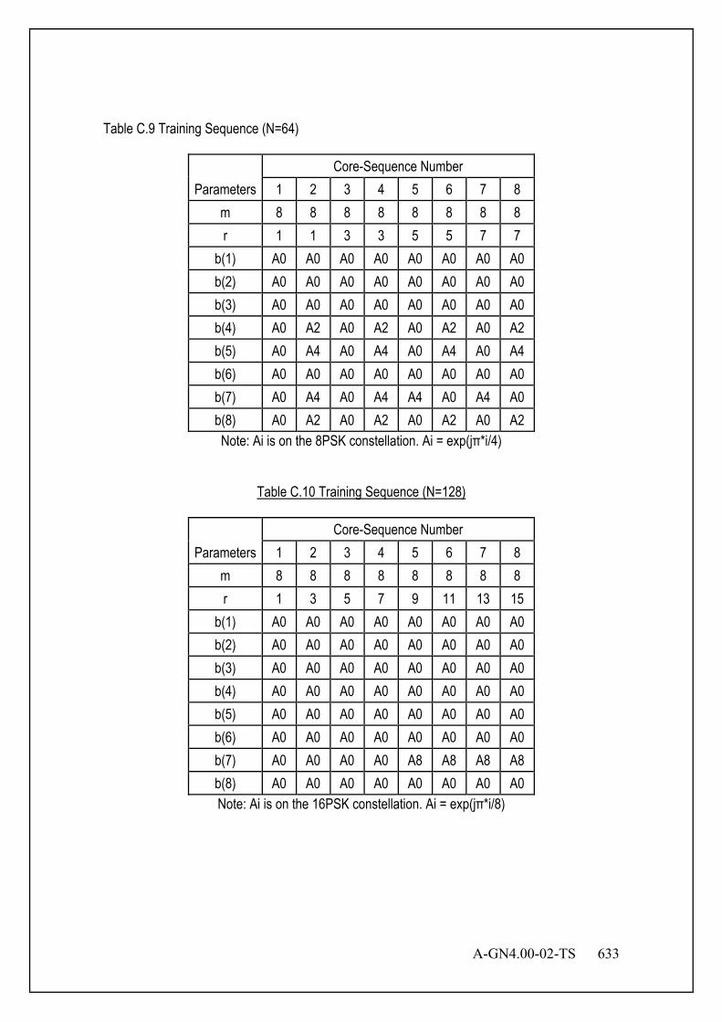
A-GN4.00-02-TS 633
Table C.9 Training Sequence (N=64)
Parameters Core-Sequence Number
1 2 3 4 5 6 7 8 m 8 8 8 8 8 8 8 8 r 1 1 3 3 5 5 7 7
b(1) A0 A0 A0 A0 A0 A0 A0 A0 b(2) A0 A0 A0 A0 A0 A0 A0 A0 b(3) A0 A0 A0 A0 A0 A0 A0 A0 b(4) A0 A2 A0 A2 A0 A2 A0 A2 b(5) A0 A4 A0 A4 A0 A4 A0 A4 b(6) A0 A0 A0 A0 A0 A0 A0 A0 b(7) A0 A4 A0 A4 A4 A0 A4 A0 b(8) A0 A2 A0 A2 A0 A2 A0 A2 Note: Ai is on the 8PSK constellation. Ai = exp(jπ*i/4)
Table C.10 Training Sequence (N=128)
Parameters Core-Sequence Number
1 2 3 4 5 6 7 8 m 8 8 8 8 8 8 8 8 r 1 3 5 7 9 11 13 15
b(1) A0 A0 A0 A0 A0 A0 A0 A0 b(2) A0 A0 A0 A0 A0 A0 A0 A0 b(3) A0 A0 A0 A0 A0 A0 A0 A0 b(4) A0 A0 A0 A0 A0 A0 A0 A0 b(5) A0 A0 A0 A0 A0 A0 A0 A0 b(6) A0 A0 A0 A0 A0 A0 A0 A0 b(7) A0 A0 A0 A0 A8 A8 A8 A8 b(8) A0 A0 A0 A0 A0 A0 A0 A0 Note: Ai is on the 16PSK constellation. Ai = exp(jπ*i/8)

634 A-GN4.00-02-TS
Table C.11 Training Sequence (N=256)
Parameters Core-Sequence Number
1 2 3 4 5 6 7 8 m 16 16 16 16 16 16 16 16 r 1 3 5 7 9 11 13 15
b(1) A0 A0 A0 A0 A0 A0 A0 A0 b(2) A0 A0 A0 A0 A0 A0 A0 A0 b(3) A0 A0 A0 A0 A0 A0 A0 A0 b(4) A0 A0 A0 A0 A0 A0 A0 A0 b(5) A0 A0 A0 A0 A0 A0 A0 A0 b(6) A0 A0 A0 A0 A0 A0 A0 A0 b(7) A0 A0 A0 A0 A0 A0 A0 A0 b(8) A0 A0 A0 A0 A0 A0 A0 A0 b(9) A0 A0 A0 A0 A0 A0 A0 A0
b(10) A0 A0 A0 A0 A4 A4 A4 A4 b(11) A0 A0 A0 A0 A8 A8 A8 A8 b(12) A0 A0 A0 A0 A0 A0 A0 A0 b(13) A0 A0 A0 A0 A12 A12 A12 A12 b(14) A0 A0 A0 A0 A4 A4 A4 A4 b(15) A0 A0 A0 A0 A8 A8 A8 A8 b(16) A0 A0 A0 A0 A8 A8 A8 A8 Note: Ai is on the 16PSK constellation. Ai = exp(jπ*i/8)

A-GN4.00-02-TS 635
Offset value for SC training sequence is shown in Table C.12. This table is referred to in Section 3.6.2.
Table C.12 Offset Value for SC Training Sequence
Sequence Size: N [symbol]
16 16 32 64 128 256
(Table C.6) (Table C.7) Offset Value 1 [symbol] 0 0 0 0 0 0 Offset Value 2 [symbol] 4 8 16 32 64 128 Offset Value 3 [symbol] 2 4 8 16 32 64 Offset Value 4 [symbol] 6 12 24 48 96 192 Offset Value 5 [symbol] 8 16 32 Offset Value 6 [symbol] 40 80 160 Offset Value 7 [symbol] 24 48 96 Offset Value 8 [symbol] 56 112 224
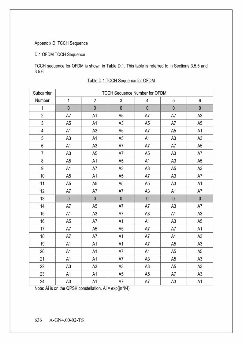
636 A-GN4.00-02-TS
Appendix D: TCCH Sequence D.1 OFDM TCCH Sequence TCCH sequence for OFDM is shown in Table D.1. This table is referred to in Sections 3.5.5 and 3.5.6.
Table D.1 TCCH Sequence for OFDM
Subcarrier Number
TCCH Sequence Number for OFDM 1 2 3 4 5 6
1 0 0 0 0 0 0 2 A7 A1 A5 A7 A7 A3 3 A5 A1 A3 A5 A7 A5 4 A1 A3 A5 A7 A5 A1 5 A3 A1 A5 A1 A3 A3 6 A1 A3 A7 A7 A7 A5 7 A3 A5 A7 A5 A3 A7 8 A5 A1 A5 A1 A3 A5 9 A1 A7 A3 A3 A5 A3
10 A5 A1 A5 A7 A3 A7 11 A5 A5 A5 A5 A3 A1 12 A7 A7 A7 A3 A1 A7 13 0 0 0 0 0 0 14 A7 A5 A7 A7 A3 A7 15 A1 A3 A7 A3 A1 A3 16 A5 A7 A1 A1 A3 A5 17 A7 A5 A5 A7 A7 A1 18 A7 A7 A1 A7 A1 A3 19 A1 A1 A1 A7 A5 A3 20 A1 A1 A7 A1 A5 A5 21 A1 A1 A7 A3 A5 A3 22 A3 A3 A3 A3 A5 A3 23 A1 A1 A5 A5 A7 A3 24 A3 A1 A7 A7 A3 A1
Note: Ai is on the QPSK constellation. Ai = exp(jπ*i/4)
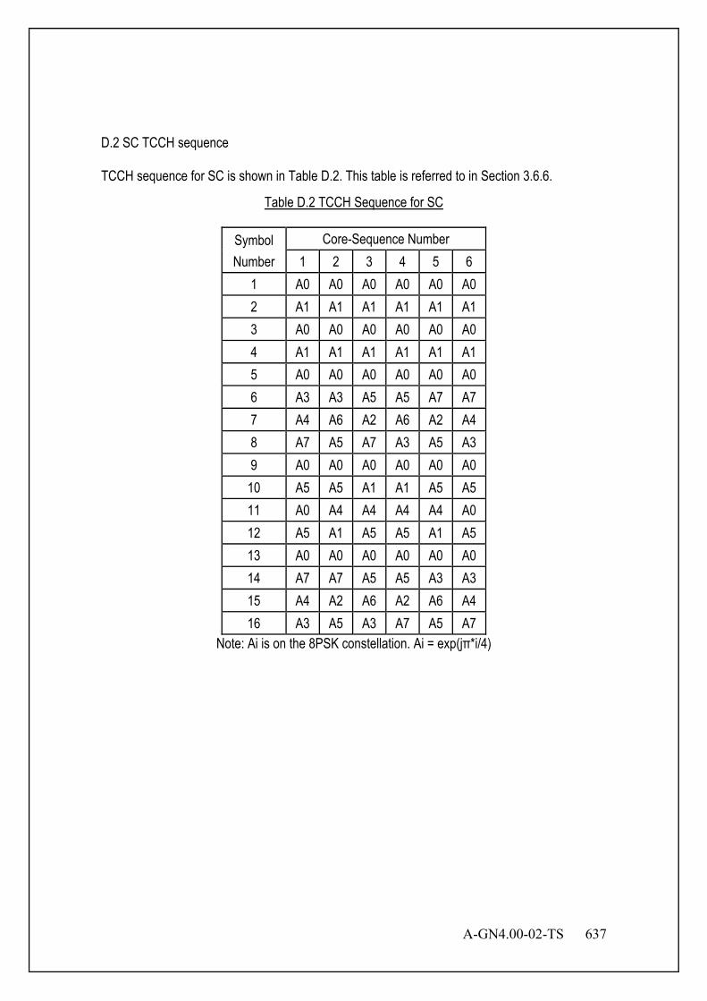
A-GN4.00-02-TS 637
D.2 SC TCCH sequence TCCH sequence for SC is shown in Table D.2. This table is referred to in Section 3.6.6.
Table D.2 TCCH Sequence for SC
Symbol Number
Core-Sequence Number 1 2 3 4 5 6
1 A0 A0 A0 A0 A0 A0 2 A1 A1 A1 A1 A1 A1 3 A0 A0 A0 A0 A0 A0 4 A1 A1 A1 A1 A1 A1 5 A0 A0 A0 A0 A0 A0 6 A3 A3 A5 A5 A7 A7 7 A4 A6 A2 A6 A2 A4 8 A7 A5 A7 A3 A5 A3 9 A0 A0 A0 A0 A0 A0
10 A5 A5 A1 A1 A5 A5 11 A0 A4 A4 A4 A4 A0 12 A5 A1 A5 A5 A1 A5 13 A0 A0 A0 A0 A0 A0 14 A7 A7 A5 A5 A3 A3 15 A4 A2 A6 A2 A6 A4 16 A3 A5 A3 A7 A5 A7
Note: Ai is on the 8PSK constellation. Ai = exp(jπ*i/4)
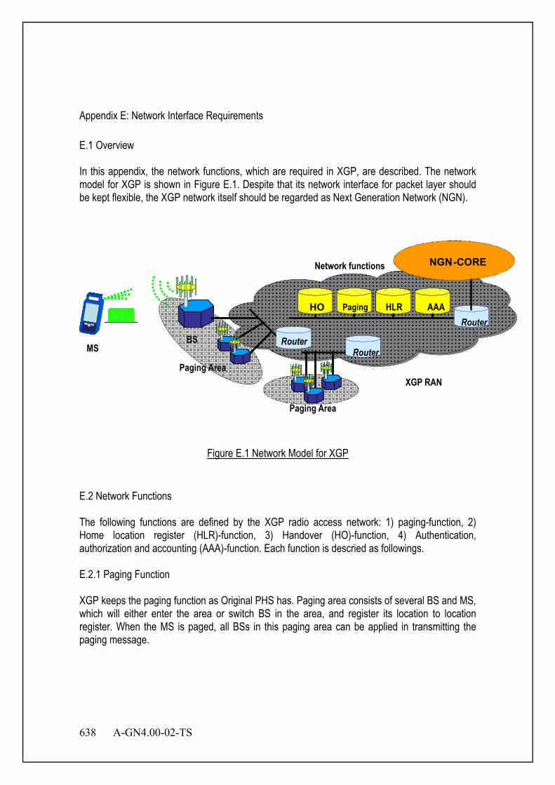
638 A-GN4.00-02-TS
Appendix E: Network Interface Requirements E.1 Overview In this appendix, the network functions, which are required in XGP, are described. The network model for XGP is shown in Figure E.1. Despite that its network interface for packet layer should be kept flexible, the XGP network itself should be regarded as Next Generation Network (NGN).
XGP RAN
NGN - CORE
MS
PagingHO HLR AA
BS
Paging HO HLR AAA
Router Router
Router
Network functions
Paging Area
Paging Area
Figure E.1 Network Model for XGP
E.2 Network Functions The following functions are defined by the XGP radio access network: 1) paging-function, 2) Home location register (HLR)-function, 3) Handover (HO)-function, 4) Authentication, authorization and accounting (AAA)-function. Each function is descried as followings. E.2.1 Paging Function XGP keeps the paging function as Original PHS has. Paging area consists of several BS and MS, which will either enter the area or switch BS in the area, and register its location to location register. When the MS is paged, all BSs in this paging area can be applied in transmitting the paging message.

A-GN4.00-02-TS 639
E.2.1.1 Paging Area Paging area is an area consisting of several BSs. The BS belonging to one paging area must share the same features about channel structure, system information, etc. Every BS is included in a certain paging group. Network controls the BS and its paging area number.
Figure E.2 Structure of Paging Area
E.2.1.2 The Recognition of Paging Area The MS can distinguish a paging area from BSID which is transmitted by BS. Paging area number is indicated by nP bits in BSID shown in Figure E.3.
Figure E.3 Broadcasting of System Information by Common Channel
BS notifies the superframe structure of the XGP system, the transceiver timing of LCCH, etc. of the whole paging area to MS.
System Type
1 bit
Operator ID
3 bits
BS-Info 40 bits
Paging Area Number np bits
System Additional ID
Sequence Number
nBL - np - 4 bits
BS Additional ID
40 - nBL bits
BSID nBL bits
Paging Area 1 Paging Area 2 BS1
BS2 BS3 BS4
GW

640 A-GN4.00-02-TS
E.2.1.3 Paging Group MS determines its own paging group and receives PCH of the paging group. The information on MS, including MSID, etc, are notified by PCH. Intermittent control for MS as shown in Figure E.4 is possible. In this example, the paging group of this MS is assigned to 2, and MS only receives the PCH 2 for paging.
P X: PCH X, BC: BCCH, SC: SCCH,
Figure E.4 An Intermittent Receipt of PCH (When It Belongs to PCH 2)
E.2.1.4 Incoming Call If the MS in a paging area has incoming-call from a network, BS will report an incoming message to MS using PCH. On the other hand, MS receives an incoming message from the PCH of the paging group to which the MS belongs. Then radio link is established to BS and the acknowledgement to the incoming message is returned. E.2.2 Home Location Register (HLR) Function Home location register (HLR), has the function to control the location information for each MS. When the power of MS is on, or when the MS is moved into another paging area, the location registration will be activated to report the paging area, where MS is now standby. HLR controls all MS location. When an MS is paged, HLR will control the paging message to the paging area, where this MS has made the last location registration.
BC
P 1
P 2
SC
P3
P4
SC
P5
BC
LCCH Superframe
P1
P2
SC
Send Timing of BS
Receive Timing of MS
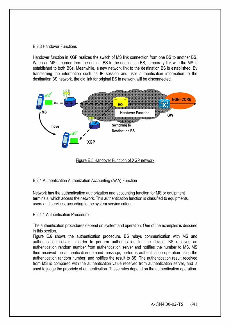
A-GN4.00-02-TS 641
E.2.3 Handover Functions Handover function in XGP realizes the switch of MS link connection from one BS to another BS. When an MS is carried from the original BS to the destination BS, temporary link with the MS is established to both BSs. Meanwhile, a new network link to the destination BS is established. By transferring the information such as IP session and user authentication information to the destination BS network, the old link for original BS in network will be disconnected.
XGP
MS
HO
Switching to Destination BS
NGN- CORE
move
Handover Function GW
Figure E.5 Handover Function of XGP network
E.2.4 Authentication Authorization Accounting (AAA) Function Network has the authentication authorization and accounting function for MS or equipment terminals, which access the network. This authentication function is classified to equipments, users and services, according to the system service criteria. E.2.4.1 Authentication Procedure The authentication procedures depend on system and operation. One of the examples is descried in this section. Figure E.6 shows the authentication procedure. BS relays communication with MS and authentication server in order to perform authentication for the device. BS receives an authentication random number from authentication server and notifies the number to MS. MS then received the authentication demand message, performs authentication operation using the authentication random number, and notifies the result to BS. The authentication result received from MS is compared with the authentication value received from authentication server, and is used to judge the propriety of authentication. These rules depend on the authentication operation.
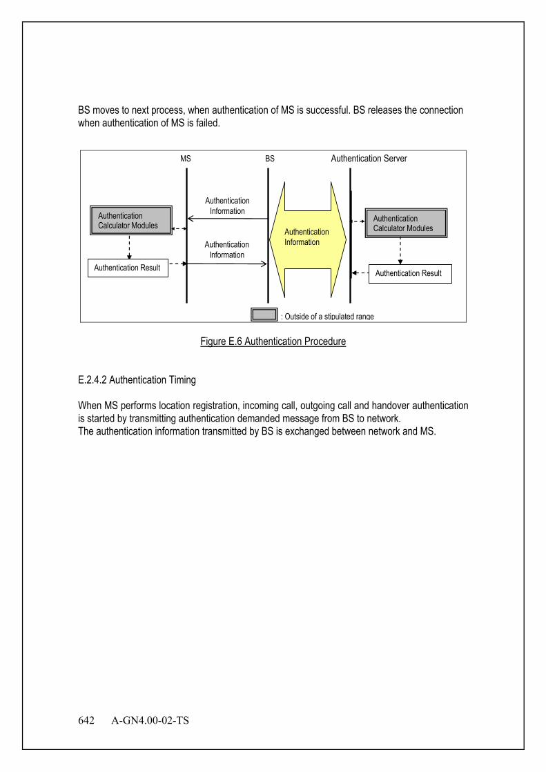
642 A-GN4.00-02-TS
BS moves to next process, when authentication of MS is successful. BS releases the connection when authentication of MS is failed.
MS Authentication Server
Authentication Information
BS
: Outside of a stipulated range
Authentication Information
Authentication Result
Authentication Calculator Modules
Authentication Result
Authentication Calculator Modules
Authentication Information
Figure E.6 Authentication Procedure
E.2.4.2 Authentication Timing When MS performs location registration, incoming call, outgoing call and handover authentication is started by transmitting authentication demanded message from BS to network. The authentication information transmitted by BS is exchanged between network and MS.

A-GN4.00-02-TS 643
Appendix F: Improvement for CCH linkbudget F.1 Overview In this appendix, the improvement for a linkbudget of CCH, Dual CCH and CCH Continuation Transmission, is described with examples because their usage are depended on system. Either or both of these function can be used in same system. Both of BS and MS can improve a linkbudget by receiving both CCH under this environment. F.2 Dual CCH Figure F.1 shows example for Dual CCH in case of allocated on each ends. their differences, the left side is CCH allocation in same slot, the other is CCH allocation in another slots. SCH number n is depended on System Bandwidth. Each CCH parameter should be same. This CCH allocation as SCH and slot is depended on system configuration.
SCH1 CCH SCH1 CCHSCH2 SCH2
~ ~ ~ ~ ~ ~ ~ ~ ~ ~
SCH n CCH SCH n CCHSlot 1 Slot 2 Slot 3 Slot 4 Slot 1 Slot 2 Slot 3 Slot 4
Figure F.1 Example allocations of Dual CCH
F.3 CCH Continuation Transmission Figure F.2 shows example allocations of CCH Continuation Transmission. Two CCHs for Continuation Transmission are set in the figure. A linkbudget improves by increasing the number of their CCHs. This number is depended on system configuration. Note that system should consider a compatibility between version 1 and 2 because the protocol version 1 does not support this function. Therefore, CCH allocation of version 1 and 2 should separate. This function applies only CCH allocation for protocol version 2. And their CCH should be also continuous allocation.
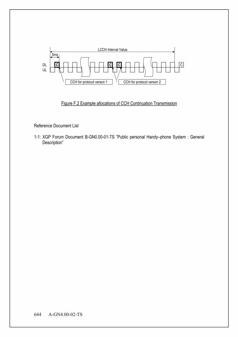
644 A-GN4.00-02-TS
DL C C C CUL
LCCH Interval Value5ms
CCH for protocol verson 1 CCH for protocol verson 2
Figure F.2 Example allocations of CCH Continuation Transmission
Reference Document List 1-1: XGP Forum Document B-GN0.00-01-TS ”Public personal Handy–phone System : General
Description”

ARIB STD-T95
C-1
Change History
Version Date History
Ver. 1.0 December 12th, 2007 Approved by the 68th ARIB Standard Assembly
Ver. 1.1 June 6th, 2008 Approved by the 70th ARIB Standard Assembly
Ver. 1.2 March 18th, 2009 Approved by the 73rd ARIB Standard Assembly
Ver. 1.3 December 16th, 2009 Approved by the 75th ARIB Standard Assembly
Ver. 2.0 July 7th, 2011 Approved by the 80th ARIB Standard Assembly
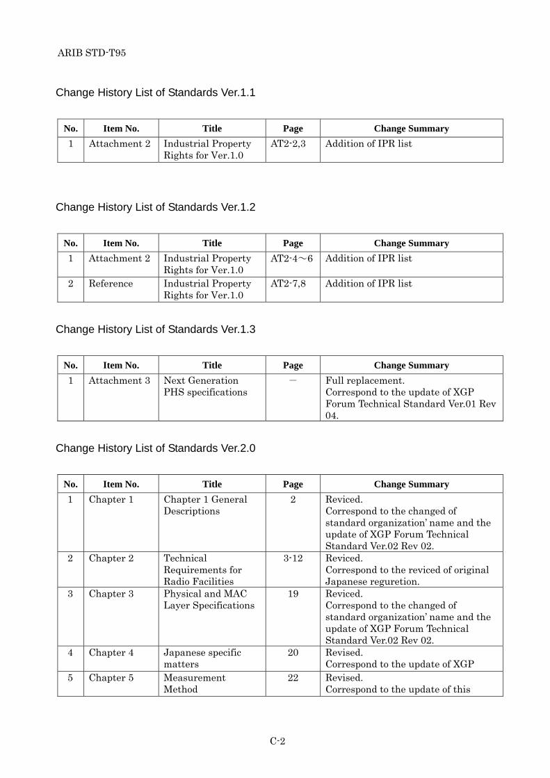
ARIB STD-T95
C-2
Change History List of Standards Ver.1.1
No. Item No. Title Page Change Summary
1 Attachment 2 Industrial Property Rights for Ver.1.0
AT2-2,3 Addition of IPR list
Change History List of Standards Ver.1.2
No. Item No. Title Page Change Summary
1 Attachment 2 Industrial Property Rights for Ver.1.0
AT2-4~6 Addition of IPR list
2 Reference Industrial Property Rights for Ver.1.0
AT2-7,8 Addition of IPR list
Change History List of Standards Ver.1.3
No. Item No. Title Page Change Summary
1 Attachment 3 Next Generation PHS specifications
- Full replacement. Correspond to the update of XGP Forum Technical Standard Ver.01 Rev 04.
Change History List of Standards Ver.2.0
No. Item No. Title Page Change Summary
1 Chapter 1 Chapter 1 General Descriptions
2 Reviced. Correspond to the changed of standard organization’ name and the update of XGP Forum Technical Standard Ver.02 Rev 02.
2 Chapter 2 Technical Requirements for Radio Facilities
3-12 Reviced. Correspond to the reviced of original Japanese reguretion.
3 Chapter 3 Physical and MAC Layer Specifications
19 Reviced. Correspond to the changed of standard organization’ name and the update of XGP Forum Technical Standard Ver.02 Rev 02.
4 Chapter 4 Japanese specific matters
20 Revised. Correspond to the update of XGP
5 Chapter 5 Measurement Method
22 Revised. Correspond to the update of this

ARIB STD-T95
C-3
standard version.
6 Attachment 3 Next Generation PHS specifications
- Full replacement. Correspond to the update of XGP Forum Technical Standard Ver.02 Rev 02.

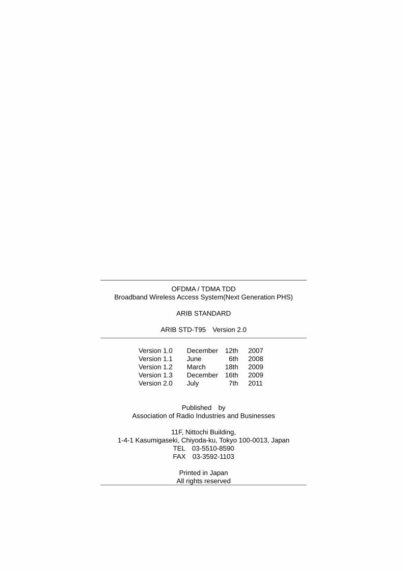
OFDMA / TDMA TDD Broadband Wireless Access System(Next Generation PHS)
ARIB STANDARD
ARIB STD-T95 Version 2.0
Version 1.0 December 12th 2007 Version 1.1 June 6th 2008 Version 1.2 March 18th 2009 Version 1.3 December 16th 2009 Version 2.0 July 7th 2011
Published by Association of Radio Industries and Businesses
11F, Nittochi Building,
1-4-1 Kasumigaseki, Chiyoda-ku, Tokyo 100-0013, Japan TEL 03-5510-8590 FAX 03-3592-1103
Printed in Japan
All rights reserved