Embed Size (px)
Citation preview
API 579 An Introduction to API RP 579: Section 9
Assessment of Crack Like Flaws

API 579
8/19/2014 2
• Classical engineering design – applied stress : material resistance
– component is defect-free
• Possible presence of defects – casting, welding, forming, develop during operation
• Fitness for Service (FFS) procedure – Determining the residual life of damaged plant
– Ensuring safe operation beyond design life
– Down-rating damaged plant below design
– Demonstrating tolerance to defects within a safety case
– Extending inspection intervals
– Reducing duration of outage and shutdown
Introduction

API 579
8/19/2014 3
Codes • API: American Petroleum Industry
• API Codes and Standards for: – design, fabrication, inspection and testing of new pressure
vessels, piping systems and storage tanks • do not address the fact that equipment degrades while in-
service
• deficiencies due to degradation or from original fabrication may be found during subsequent inspections.
• Can be applied to other industries
• API Codes – API 510: Pressure vessel inspection code
– API 570: Piping inspection code
– API 653: Tank inspection code
– API 580: Risk based inspection
• API 579

API 579
8/19/2014 4
API 579
• to ensure safety:plant personnel, public
• to provide sound FFS assessment procedures
• to ensure consistent remaining life predictions
• to enhance long-term economic viability

API 579
8/19/2014 5
API 579
• API's Recommended Practice 579 for FFS
• API 579 can be used to make run-repair-replace decisions
• The 1,000-page document is organized into modules
• Each section is based on a type of flaw or damage, such as crack-like flaws
• The document is primarily aimed at the petrochemical industry
• types of damage listed seen in petrochemical applications – they are present in other industries

API 579
8/19/2014 6
Overview of Damage Assessment Procedures
Section
1 Introduction and Scope
2 Outline of Overall Methodology
3 Brittle Fracture
4 General Metal Loss
5 Local Metal Loss
6 Pitting Corrosion
7 Blisters and Laminations
8 Weld Misalignments and Shell Distortions
9 Crack Like Flaws
10 High Temp. Operation and Creep
11 Fire Damage

API 579
8/19/2014 7
Methodology for All Damage Types
1 Flaw and damage mechanism identification
2 Applicability and limitations of the FFS assessment procedures
3 Data requirements
4 Assessment techniques and acceptance criteria
5 Remaining life evaluation
6 Remediation
7 In-service monitoring
8 Documentation

API 579
8/19/2014 8
Assessment Levels • Three levels of assessment for each flaw and
damage type – Level 1 to 3
• Assessment level – Conservatism
– Amount of information required
– Skill of the assessor
– Complexity of analysis
• Level 1 – NDE inspector
• Level 2 – Plant Engineer
• Level 3 – FFS Expert

API 579
8/19/2014 9
API 579 Section 9 - ASSESSMENT OF CRACK-LIKE FLAWS
• FFS for crack like flaws
• Based on Failure Assessment Diagram (FAD) method
• Crack like flaws observed from inspection: – planar flaws
– Length, depth, sharp root radius
– Conservative to treat volumetric flaws as cracks • Micro-cracks at root
• Relative flaw tolerance at design stage – Risk to fracture
– a/t = 25%, length = 6a

API 579
8/19/2014 10
Applicability and Limitations of the Procedure
• Level 1 and 2
– Original Design Criteria
– Operating temperature less than Creep range
– Dynamic Loading effects not significant
– No in-service crack growth

API 579
8/19/2014 11
Applicability and Limitations of the Procedure : Level 1
• Geometries – Flat plate, cylinder or sphere
– R/t > 5
– t < 38 mm
– Away from major structural discontinuity
• Loads – Only membrane stress field, within design limits
• Material – C-Steel with specified max. tensile prop. And
min. fracture properties

API 579
8/19/2014 12
Data Requirement
• Original Equipment Design Data
• Maintenance and equipment history
• Loads and stresses
• Material properties
• Flaw Characterization
• Recommendation for inspection techniques

API 579
8/19/2014 13
Flaw Characterization
• Simple geometry, amenable for fracture mechanics analysis
• Objective is to get a crack of conservative size in plane to maximum principal stress direction
• Cracks from inspection: – irregular in shape
– arbitrarily oriented
– multiple cracks
– branched cracks

API 579
8/19/2014 14
Flaw Characterization (Shape)
Through Wall Flaw
Surface Flaw
Embedded Flaw

API 579
8/19/2014 15
Flaw Characterization (length) when flaw is not normal to principal stress
direction
• Conservative Option
– Co (measured length), C (length used in calculations, normal to max. stresses)
– Take C = Co
• Equivalent flaw length
– Inclined cracks -> align itself perpendicular to the applied stress
– Mixed mode to Mode I crack
– Equivalent Mode I from energy considerations

API 579
8/19/2014 16
Flaw Characterization (Length)
0 1 2, ,c c f

API 579
8/19/2014 17
Flaw Characterization (depth)
• Depth difficult to measure
• A. Flaw depth by default values
– Through wall flaw, a = t,
– Surface flaw,
• B. Flaw depth from actual measurements
– Normal flaw, a=ao
min , length=2ca t c

API 579
8/19/2014 18
Flaw Characterization (Depth)
oa a W

API 579
8/19/2014 19
Flaw Characterization (Branch Crack)
API 579
8/19/2014 20
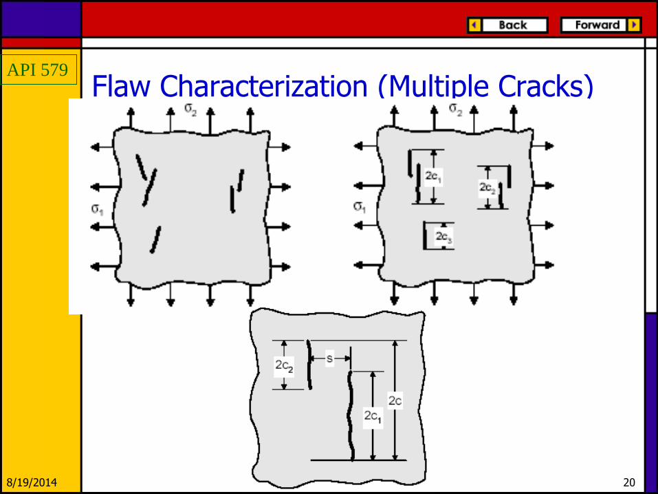
Flaw Characterization (Multiple Cracks)

API 579
8/19/2014 21
Level 1 Analysis • STEP 1 – Determine the load cases and temperatures:
operating and design conditions.
• STEP 2 – Determine the length and depth of the crack: characterize
• STEP 3 – Determine the case from the list below
o Flat Plate, Crack-Like Flaw Parallel To Joint
o Cylinder, Longitudinal Joint, Crack-Like Flaw Parallel To Joint
o Cylinder, Longitudinal Joint, Crack-Like Perpendicular To Joint
o Cylinder, Circumferential Joint, Crack-Like Flaw Parallel To Joint
o Cylinder, Circumferential Joint, Crack-Like Flaw Perpendicular To Joint
o Sphere, Circumferential Joint, Crack-Like Flaw Parallel To Joint
o Sphere, Circumferential Joint, Crack-Like Flaw Perpendicular To Joint

API 579
8/19/2014 22
Level 1 analysis
¼ t, flaw
t flaw
A – flaw in base metal.
B –flaw in weld metal that has been subject to PWHT.
C –flaw in weld metal that has not been subject to PWHT
Tref = use 38oC (material specific
can also be obtained from
Section 3)
At Tref +33o Cv = 68J, l.e. >.89mm

API 579
8/19/2014 23
Failure Assessment Diagram
' ref
r
ys
L
' Ir
mat
KK
K
r rK f L

API 579
8/19/2014 24
Advantages of FAD
• Double criteria approach:
– Fracture
• LEFM
• EPFM
– Collapse
• Elasto-Plastic Fracture Mechanics:
– J-Integral calculation not required

API 579
8/19/2014 25
Level 2 Analysis
• If the component does not meet the Level 1 Assessment requirements then a Level 2 or Level 3 Assessment can be done.
• Method A: Using partial safety factors
– Factor for applied loading
– Factor for material toughness
– Factor for flaw dimensions
– Based on probabilistic methods

API 579
8/19/2014 26
Level 2 Analysis 1– Evaluate operating conditions and determine the pressure, temperature and loading combinations to be evaluated.
2–Stress distributions at the location of the flaw. Classify Primary stress
Secondary stress
Residual stress
Appendix E of API 579 contains a compendium of residual stress distributions for various weld geometries
3 – Determine the material properties
yield strength
tensile strength
fracture toughness

API 579
8/19/2014 27
Level 2 Analysis • Appendix F of API 579 contains information
on material properties, including toughness
• Appendix does not contain a database of toughness values
• It provides correlations and estimation methods
• For ferritic steels, there are lower-bound correlations of toughness to Charpy transition temperature – From Sections III and XI of the ASME boiler and
pressure vessel code

API 579
8/19/2014 28
Level 2 Analysis API 579 endorses the use of the fracture toughness Master Curve, as implemented in ASTM Standard E 1921-97
4 – Determine the crack dimensions: characterize
5 – Modify the primary stress, material fracture toughness, and flaw size using the Partial Safety Factors ( PSF )
.
.
m m S
b b S
P P PSF
P P PSF
matmat
k
KK
PSF . aa a PSF

API 579
8/19/2014 29
Need for Partial safety Factors (PSF)
Consider a Design
R = L1 + L2 + L3
Let the factor of safety be 1.5
Thus:
R/(L1+L2+L3) = 1.5
1.5 to account for scatter in R, L
Probability of failure P(R < [L1+L2+L3])

API 579
8/19/2014 30
Estimating the Probability of failure
Let all the variables R, L1, L2, L3 follow a normal distribution.
Coeff. Of Var (/ m)
R 0.1
L1 0.1
L2 0.2
L3 0.3

API 579
8/19/2014 31
Reliability Index
The reliability index is given by
2
3
2
2
2
1
2
321
mmmm
R
R
Now we will try to estimate probability
of failure for different load combinations
API 579
8/19/2014 32
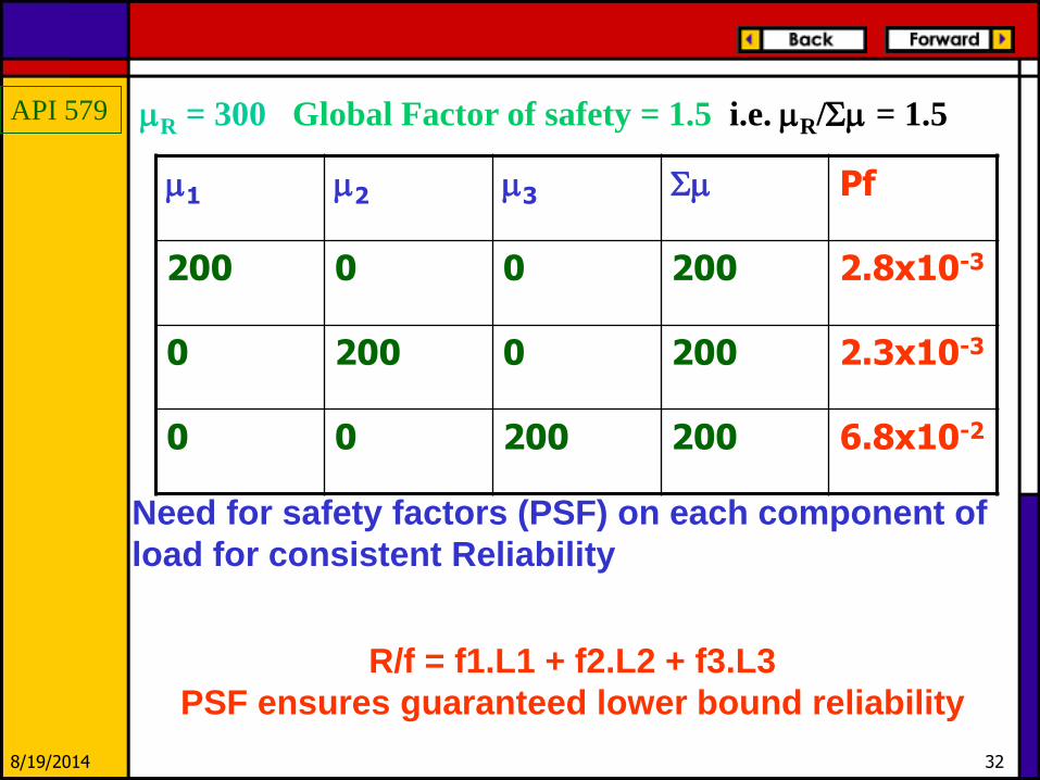
m1 m2 m3 Sm Pf
200 0 0 200 2.8x10⁻³
0 200 0 200 2.3x10⁻³
0 0 200 200 6.8x10⁻²
mR = 300 Global Factor of safety = 1.5 i.e. mR/Sm = 1.5
Need for safety factors (PSF) on each component of
load for consistent Reliability
R/f = f1.L1 + f2.L2 + f3.L3
PSF ensures guaranteed lower bound reliability
API 579
8/19/2014 33
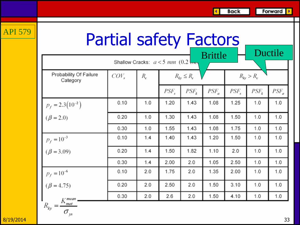
Partial safety Factors Ductile Brittle

API 579
8/19/2014 34
Level 2 Analysis 6 – Compute the reference stress for primary stresses
–reference stress solutions: Appendix D
7 – Compute the Load Ratio
8 – Compute the stress intensity attributed to the primary loads
9 – Compute the reference stress for secondary and residual stresses (used for F)
10 – Compute the stress intensity attributed to the secondary and residual stresses
11 – Compute the plasticity interaction factor, F in presence of secondary loads
p
refp
r
y
L

API 579
8/19/2014 35
Level 2 Analysis 12 – Determine toughness ratio
13 – Evaluate results on FAD
P SR
I Ir
mat
K KK
K
F
2 6
(max)1 0.14 0.3 0.7exp 0.65 for P P P P
r r r r rK L L L L

API 579
8/19/2014 36
Level 2 Analysis
If Partial safety Factors are not used
0
0.7
0 0.2 0.4 0.6 0.8 1Lr
Kr

API 579
8/19/2014 37
Residual Stress Profiles
• Listed in Appendix E of API 579 Section 9
• Residual stress distributions are provided for the following weld joint configurations – Full Penetration Welds in Piping and Pressure Vessel
Cylindrical Shells
– Full Penetration Welds in Spheres and Pressure Vessel Heads
– Full Penetration Welds in Storage Tanks
– Full Penetration and Fillet Welds at Corner Joints
– Fillet Welds at Tee Joints
– Repair Welds

API 579
8/19/2014 38
Residual stress profiles
• Based on upper bound values of the extensive numerical analyses and a literature survey of published results
• Residual stress distributions are provided for both the as-welded and PWHT conditions
• Distinction is not made concerning the material of construction – Weld joint geometry – Single V-Type – Double V-Type – Fillet welds – Repair welds

API 579
8/19/2014 39
Data required • The material specification • The material specified minimum yield strength • The wall thickness of the component • The heat input used to make the weld • The type of weld (i.e. girth or circumferential
joint, longitudinal seam, repair weld, or attachment weld)
• The weld joint configuration (i.e. single V-groove, double V-groove, corner joint, fillet weld, or repair weld)
• Procedures aimed at reducing the residual stress level – hydrotest to 150% of the maximum allowable
working pressure (MAWP)per the ASME Code, Section VIII,
– post weld heat treatment per the original construction code

API 579
8/19/2014 40
Level 3 Analysis Method A Assessment –Level 2 the FAD with user specified Partial Safety Factors based on a risk assessment
Method B Assessment – FAD is constructed based on the actual material properties
1 23
(max) for 0.02
1 for 0
P
r ysrefP P P
r r r rP
r ys ref
P P
r r r
LEK L L L
L E
K L L
1
ln 1
Where subscripts t = true, es = engineering
t es es
t es

API 579
8/19/2014 41
Level 3 Analysis Method C Assessment –FAD is constructed
based on the actual loading conditions, component geometry and material properties
Method D Assessment – This method is a ductile tearing analysis where the fracture tearing resistance is defined as a function of the amount of stable ductile tearing
elasticr
total
JK
J

API 579
8/19/2014 42
Level 3 Analysis
• Method E Assessment – The recognized assessment procedures listed below are subject to supplemental requirements that may include the use of Partial Safety Factors or a probabilistic analysis.
• BS PD6493 or BS 7910
• Nuclear Electric R-6
• SAQ/FoU Report 96/08
• WES 2805 – 1997
• DPFAD Methodology
• EPFM using the J-integral
• The J-integral-Tearing Modulus method

API 579
8/19/2014 43
Remaining Life Assessment (RLA)
• Sub-critical Crack Growth
– Crack growth by fatigue
– Crack growth by stress corrosion cracking
– Crack growth by hydrogen assisted cracking
– Crack growth by corrosion fatigue
• Growth of a pre-existing crack is controlled by a crack tip stress intensity factor
• Laws for crack growth rates for these mechanisms have been provided in Appendix F

API 579
8/19/2014 44
Difficulties in RLA
• Crack growth rates can be highly sensitive to changes in the process environment
– Models are fitted in carefully controlled conditions in a laboratory experiment
• Cracking often occurs as the result of an upset in operating conditions
– Average crack growth rate would be meaningless in such instances
• New cracks can initiate at other locations in the structure

API 579
8/19/2014 45
Procedure for RLA 1 – Perform a Level 3 assessment for the initial crack size
If the component is acceptable apply remedial measures to prevent further crack growth
2 – If effective remedial measures are not possible and slow sub-critical crack growth is expected
If a crack growth law exists for the material and service environment: a crack growth analysis can be performed else, a leak-before break analysis should be performed

API 579
8/19/2014 46
Procedure for RLA
3 – Compute the stress at the flaw based on the future operating conditions
4 – Determine an increment in crack growth
5 – Perform a Level 3 assessment for the current crack size If the assessment point is outside of the FAD or the crack is re-categorized as a through-wall crack, then go to STEP 6; otherwise, go to STEP
4 and continue to grow the crack

API 579
8/19/2014 47
Procedure for RLA 6 – Determine the time or number of stress cycles for the current crack size (ao, co) to reach the limiting flaw
size Acceptable if time to reach the limiting flaw size,with FOS, is more than the required operating period
If the depth of the limiting flaw size is re-categorized as a through-wall thickness crack, the conditions for an acceptable leak before break (LBB) criteria should be
satisfied
7 – At the next inspection, establish the actual crack growth rate, and re-evaluate the new flaw conditions. Alternatively, repair or replace the component or apply effective mitigation measures

API 579
8/19/2014 48
LBB Procedure
It may be possible to show that a flaw can grow through the wall of a component without causing a catastrophic failure
In such cases, a leak can be detected (taking into consideration the contained fluid and type of insulation) and remedial action could be initiated to avoid a component failure

API 579
8/19/2014 49
Leak Before Break
API 579
8/19/2014 50
LBB Procedure Limitations
The leak should be readily detectable
Insulation
Tight crack
Contained fluid
The LBB methodology may not be suitable for flaws near stress concentrations or regions of high residual stress

API 579
8/19/2014 51
LBB Limitations
Flaw at a stress concentration
Flaw subjected to high
residual stresses
Flaw growth in
predominantly length
direction

API 579
8/19/2014 52
LBB Limitations
Crack growth rate high
Adequate time must be available to discover the
leak and take the necessary action
Possible adverse consequences of developing a leak
hazardous materials
fluids operating below their boiling point
fluids operating above their auto-ignition temperature
API 579
8/19/2014 53
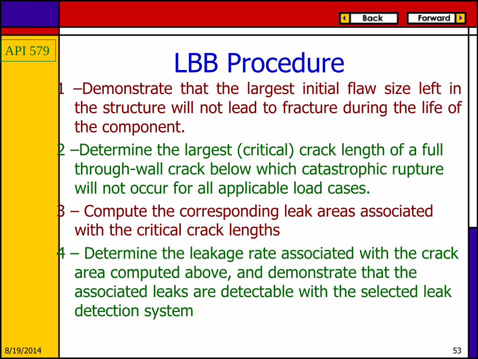
LBB Procedure 1 –Demonstrate that the largest initial flaw size left in
the structure will not lead to fracture during the life of the component.
2 –Determine the largest (critical) crack length of a full through-wall crack below which catastrophic rupture will not occur for all applicable load cases.
3 – Compute the corresponding leak areas associated with the critical crack lengths
4 – Determine the leakage rate associated with the crack area computed above, and demonstrate that the associated leaks are detectable with the selected leak detection system

API 579
8/19/2014 54
Remediation • Method 1 – Removal or repair of the crack. The crack
may be removed by blend grinding
• Method 2 – Use of a crack arresting detail or device
• Method 3 – Performing physical changes to the process stream
• Method 4 – Application of solid barrier linings or coatings to keep the environment isolated from the base metal
• Method 5 – Injection of water and/or chemicals on a continuous basis to modify the environment or the surface of the metal
• Method 6 – Application of weld overlay
• Method 7 – Use of leak monitoring and leak-sealing devices

API 579
8/19/2014 55
In-service monitoring In all cases where sub-critical in-service crack growth is permitted
– in-service monitoring or
–monitoring at a shutdown inspection
of the crack growth by NDE is required. The applicable NDE method will depend
on the specific case.
API 579
8/19/2014 56
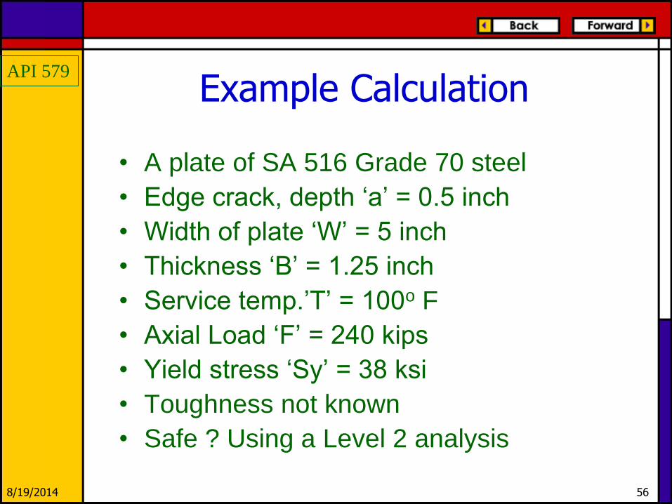
Example Calculation
• A plate of SA 516 Grade 70 steel
• Edge crack, depth ‘a’ = 0.5 inch
• Width of plate ‘W’ = 5 inch
• Thickness ‘B’ = 1.25 inch
• Service temp.’T’ = 100o F
• Axial Load ‘F’ = 240 kips
• Yield stress ‘Sy’ = 38 ksi
• Toughness not known
• Safe ? Using a Level 2 analysis

API 579
8/19/2014 57
Solution
• Kc, from Table 3.3 of API 579, Tref = 40o F

API 579
8/19/2014 58
Solution

API 579
8/19/2014 59
FAD
Example of Level 2 FAD
0
0.2
0.4
0.6
0.8
0 0.2 0.4 0.6 0.8 1 1.2
Lr
Kr
(1.12, 0.559)Load = 171 kips

API 579
8/19/2014 60
Thank You