Embed Size (px)
Citation preview
Adafruit HUZZAH ESP8266 breakoutCreated by lady ada
Last updated on 2016-02-07 10:00:46 PM EST
24
10111213141416161617
21212325272831313333
353738424343434446
Guide Contents
Guide ContentsOverviewPinoutsPower PinsSerial pinsGPIO pinsAnalog PinsOther control pinsAssembly
Prepare the header strip:Add the breakout board:And Solder!
Using NodeMCU LuaConnect USB-Serial cableOpen up serial consoleHello world!Scanning & Connecting to WiFiWebClient exampleUsing Arduino IDEConnect USB-Serial cableInstall the Arduino IDE 1.6.4 or greater
Install the ESP8266 Board Package
Setup ESP8266 SupportBlink TestConnecting via WiFiOther OptionsDownloadsMore info about the ESP8266SchematicFabrication printF.A.Q.
© Adafruit Industries https://learn.adafruit.com/adafruit-huzzah-esp8266-breakout Page 2 of 46

© Adafruit Industries https://learn.adafruit.com/adafruit-huzzah-esp8266-breakout Page 3 of 46
Overview
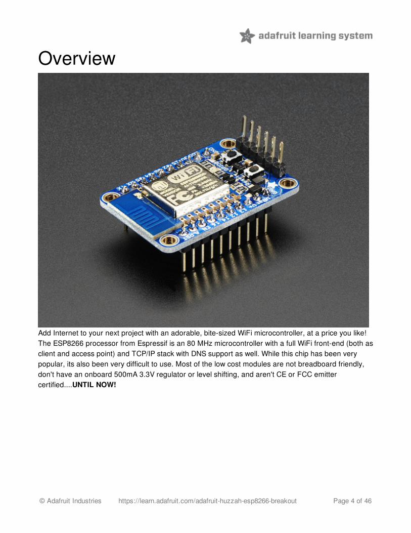
Add Internet to your next project with an adorable, bite-sized WiFi microcontroller, at a price you like!The ESP8266 processor from Espressif is an 80 MHz microcontroller with a full WiFi front-end (both asclient and access point) and TCP/IP stack with DNS support as well. While this chip has been verypopular, its also been very difficult to use. Most of the low cost modules are not breadboard friendly,don't have an onboard 500mA 3.3V regulator or level shifting, and aren't CE or FCC emittercertified....UNTIL NOW!
© Adafruit Industries https://learn.adafruit.com/adafruit-huzzah-esp8266-breakout Page 4 of 46
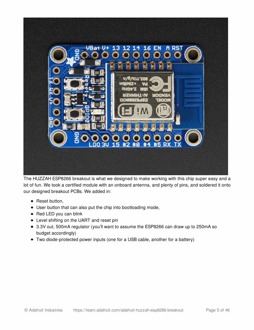
The HUZZAH ESP8266 breakout is what we designed to make working with this chip super easy and alot of fun. We took a certified module with an onboard antenna, and plenty of pins, and soldered it ontoour designed breakout PCBs. We added in:
Reset button,User button that can also put the chip into bootloading mode,Red LED you can blinkLevel shifting on the UART and reset pin3.3V out, 500mA regulator (you'll want to assume the ESP8266 can draw up to 250mA sobudget accordingly)Two diode-protected power inputs (one for a USB cable, another for a battery)
© Adafruit Industries https://learn.adafruit.com/adafruit-huzzah-esp8266-breakout Page 5 of 46
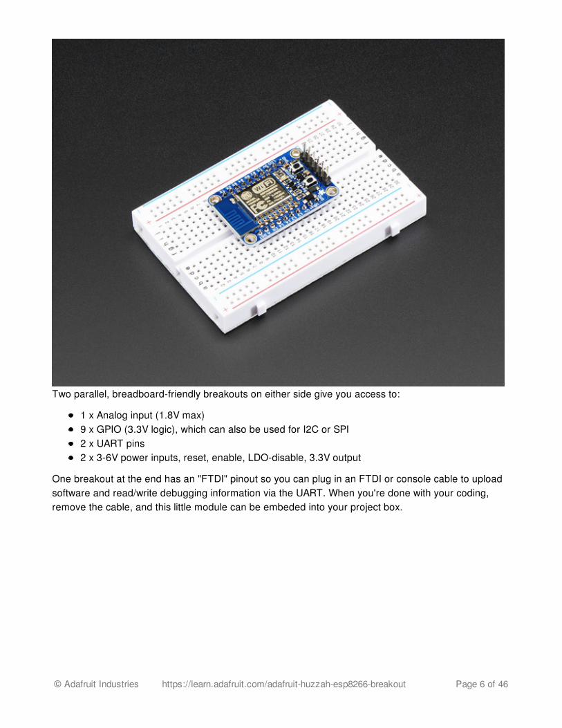
Two parallel, breadboard-friendly breakouts on either side give you access to:
1 x Analog input (1.8V max)9 x GPIO (3.3V logic), which can also be used for I2C or SPI2 x UART pins2 x 3-6V power inputs, reset, enable, LDO-disable, 3.3V output
One breakout at the end has an "FTDI" pinout so you can plug in an FTDI or console cable to uploadsoftware and read/write debugging information via the UART. When you're done with your coding,remove the cable, and this little module can be embeded into your project box.
© Adafruit Industries https://learn.adafruit.com/adafruit-huzzah-esp8266-breakout Page 6 of 46
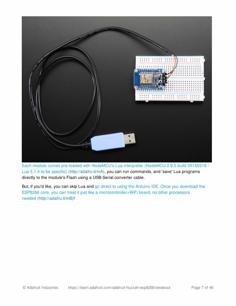
Each module comes pre-loaded with NodeMCU's Lua interpreter (NodeMCU 0.9.5 build 20150318 /Lua 5.1.4 to be specific) (http://adafru.it/inA), you can run commands, and 'save' Lua programsdirectly to the module's Flash using a USB-Serial converter cable.
But, if you'd like, you can skip Lua and go direct to using the Arduino IDE. Once you download theESP8266 core, you can treat it just like a microcontroller+WiFi board, no other processorsneeded (http://adafru.it/inB)!
© Adafruit Industries https://learn.adafruit.com/adafruit-huzzah-esp8266-breakout Page 7 of 46
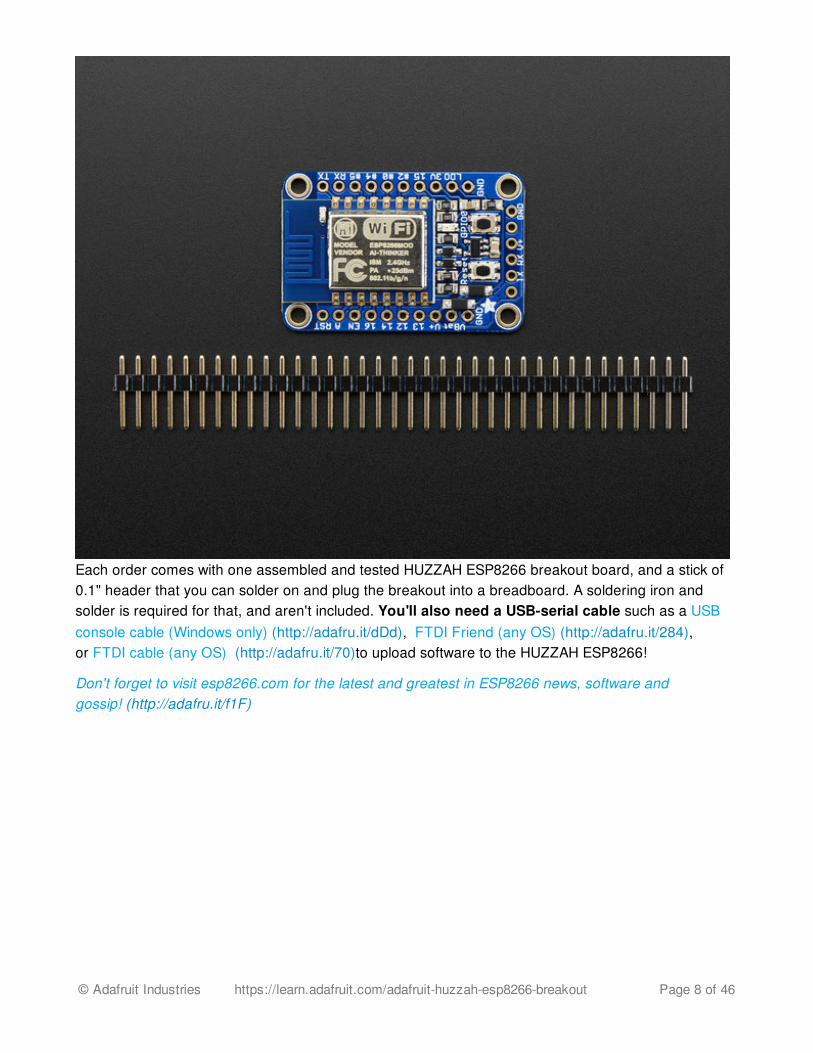
Each order comes with one assembled and tested HUZZAH ESP8266 breakout board, and a stick of0.1" header that you can solder on and plug the breakout into a breadboard. A soldering iron andsolder is required for that, and aren't included. You'll also need a USB-serial cable such as a USBconsole cable (Windows only) (http://adafru.it/dDd), FTDI Friend (any OS) (http://adafru.it/284),or FTDI cable (any OS) (http://adafru.it/70)to upload software to the HUZZAH ESP8266!
Don't forget to visit esp8266.com for the latest and greatest in ESP8266 news, software andgossip! (http://adafru.it/f1F)
© Adafruit Industries https://learn.adafruit.com/adafruit-huzzah-esp8266-breakout Page 8 of 46
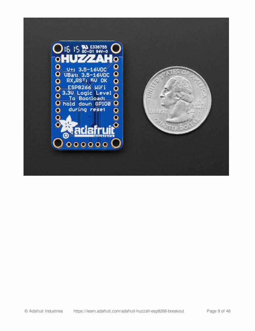
© Adafruit Industries https://learn.adafruit.com/adafruit-huzzah-esp8266-breakout Page 9 of 46
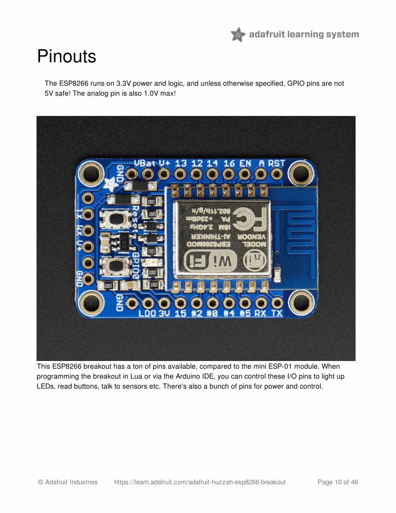
PinoutsThe ESP8266 runs on 3.3V power and logic, and unless otherwise specified, GPIO pins are not5V safe! The analog pin is also 1.0V max!
This ESP8266 breakout has a ton of pins available, compared to the mini ESP-01 module. Whenprogramming the breakout in Lua or via the Arduino IDE, you can control these I/O pins to light upLEDs, read buttons, talk to sensors etc. There's also a bunch of pins for power and control.
© Adafruit Industries https://learn.adafruit.com/adafruit-huzzah-esp8266-breakout Page 10 of 46
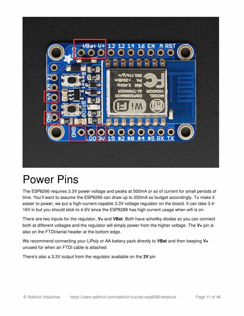
Power PinsThe ESP8266 requires 3.3V power voltage and peaks at 500mA or so of current for small periods oftime. You'll want to assume the ESP8266 can draw up to 250mA so budget accordingly. To make iteasier to power, we put a high-current-capable 3.3V voltage regulator on the board. It can take 3.4-16V in but you should stick to 4-6V since the ESP8288 has high current usage when wifi is on.
There are two inputs for the regulator, V+ and VBat. Both have schottky diodes so you can connectboth at different voltages and the regulator will simply power from the higher voltage. The V+ pin isalso on the FTDI/serial header at the bottom edge.
We recommend connecting your LiPoly or AA battery pack directly to VBat and then keeping V+unused for when an FTDI cable is attached
There's also a 3.3V output from the regulator available on the 3V pin
© Adafruit Industries https://learn.adafruit.com/adafruit-huzzah-esp8266-breakout Page 11 of 46
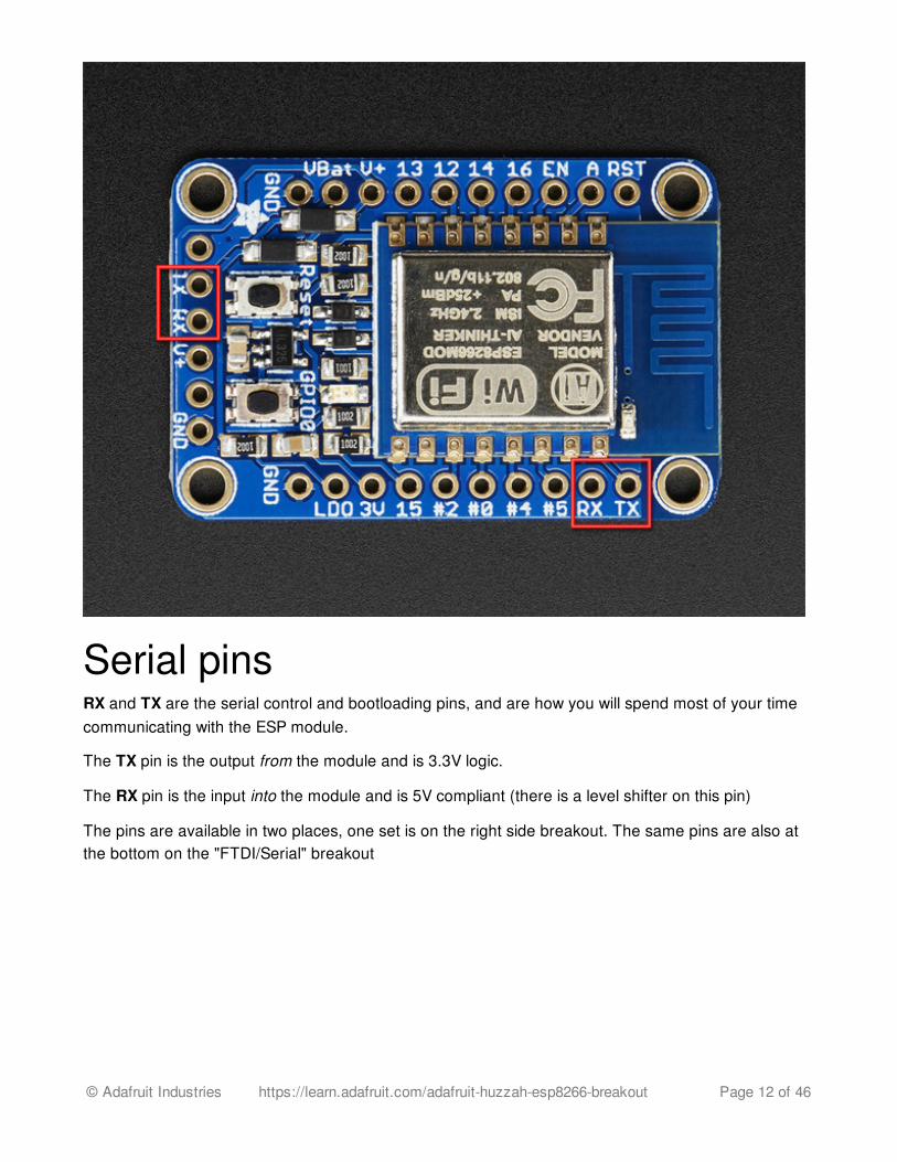
Serial pinsRX and TX are the serial control and bootloading pins, and are how you will spend most of your timecommunicating with the ESP module.
The TX pin is the output from the module and is 3.3V logic.
The RX pin is the input into the module and is 5V compliant (there is a level shifter on this pin)
The pins are available in two places, one set is on the right side breakout. The same pins are also atthe bottom on the "FTDI/Serial" breakout
© Adafruit Industries https://learn.adafruit.com/adafruit-huzzah-esp8266-breakout Page 12 of 46
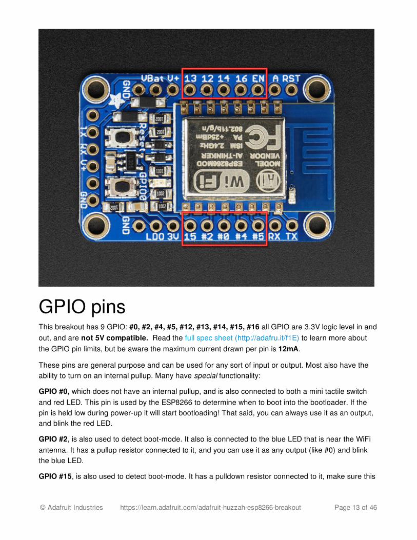
GPIO pinsThis breakout has 9 GPIO: #0, #2, #4, #5, #12, #13, #14, #15, #16 all GPIO are 3.3V logic level in andout, and are not 5V compatible. Read the full spec sheet (http://adafru.it/f1E) to learn more aboutthe GPIO pin limits, but be aware the maximum current drawn per pin is 12mA.
These pins are general purpose and can be used for any sort of input or output. Most also have theability to turn on an internal pullup. Many have special functionality:
GPIO #0, which does not have an internal pullup, and is also connected to both a mini tactile switchand red LED. This pin is used by the ESP8266 to determine when to boot into the bootloader. If thepin is held low during power-up it will start bootloading! That said, you can always use it as an output,and blink the red LED.
GPIO #2, is also used to detect boot-mode. It also is connected to the blue LED that is near the WiFiantenna. It has a pullup resistor connected to it, and you can use it as any output (like #0) and blinkthe blue LED.
GPIO #15, is also used to detect boot-mode. It has a pulldown resistor connected to it, make sure this
© Adafruit Industries https://learn.adafruit.com/adafruit-huzzah-esp8266-breakout Page 13 of 46
pin isn't pulled high on startup. You can always just use it as an output
GPIO #16 can be used to wake up out of deep-sleep mode, you'll need to connect it to the RESET pin
Rev A of this board has GPIO #4 and #5 swapped (the modules changed pinouts on us) so if#4/#5 aren't working for you, try swapping! We'll fix in the next PCB run
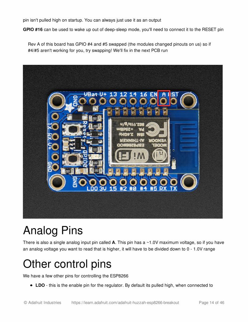
Analog PinsThere is also a single analog input pin called A. This pin has a ~1.0V maximum voltage, so if you havean analog voltage you want to read that is higher, it will have to be divided down to 0 - 1.0V range
Other control pinsWe have a few other pins for controlling the ESP8266
LDO - this is the enable pin for the regulator. By default its pulled high, when connected to
© Adafruit Industries https://learn.adafruit.com/adafruit-huzzah-esp8266-breakout Page 14 of 46
ground it will turn off the 3.3V regulator and is an easy way to cut power off to the whole setup.There is a 10K pullup is to whatever is greater, V+ or VBat.RST - this is the reset pin for the ESP8266, pulled high by default. When pulled down to groundmomentarily it will reset the ESP8266 system. This pin is 5V compliant.EN (CH_PD) - This is the enable pin for the ESP8266, pulled high by default. When pulled downto ground momentarily it will reset the ESP8266 system. This pin is 3.3V logic only
© Adafruit Industries https://learn.adafruit.com/adafruit-huzzah-esp8266-breakout Page 15 of 46
Assembly
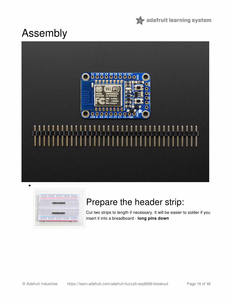
Prepare the header strip:Cut two strips to length if necessary. It will be easier to solder if youinsert it into a breadboard - long pins down
© Adafruit Industries https://learn.adafruit.com/adafruit-huzzah-esp8266-breakout Page 16 of 46
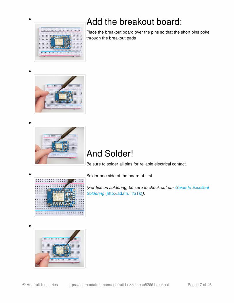
Add the breakout board:Place the breakout board over the pins so that the short pins pokethrough the breakout pads
And Solder!Be sure to solder all pins for reliable electrical contact.
Solder one side of the board at first
(For tips on soldering, be sure to check out our Guide to ExcellentSoldering (http://adafru.it/aTk)).
© Adafruit Industries https://learn.adafruit.com/adafruit-huzzah-esp8266-breakout Page 17 of 46
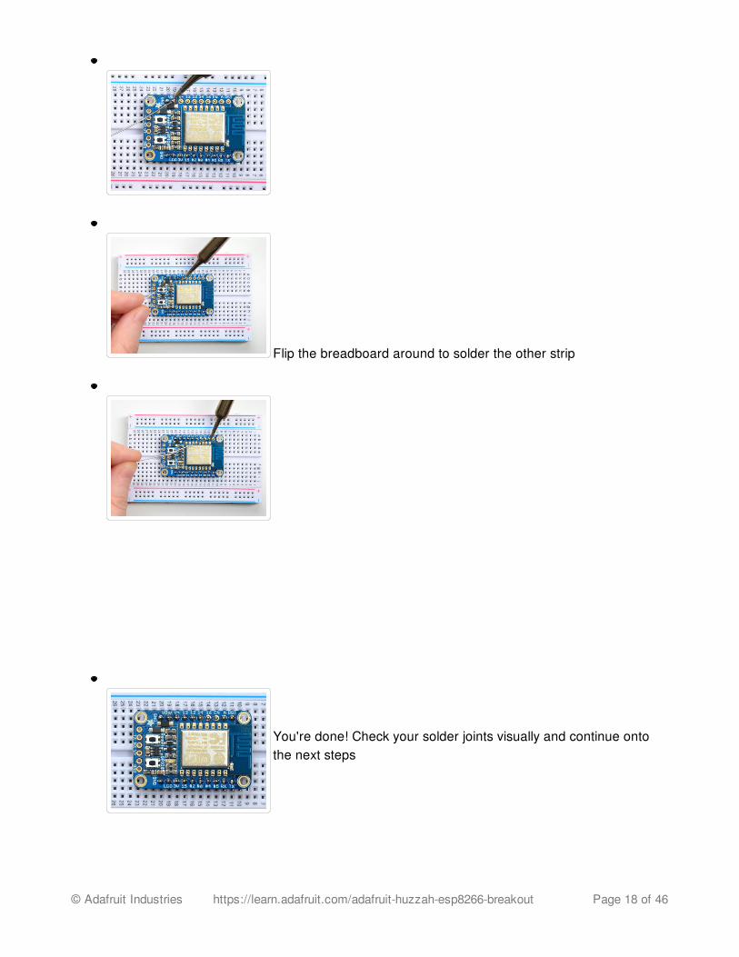
Flip the breadboard around to solder the other strip
You're done! Check your solder joints visually and continue ontothe next steps
© Adafruit Industries https://learn.adafruit.com/adafruit-huzzah-esp8266-breakout Page 18 of 46
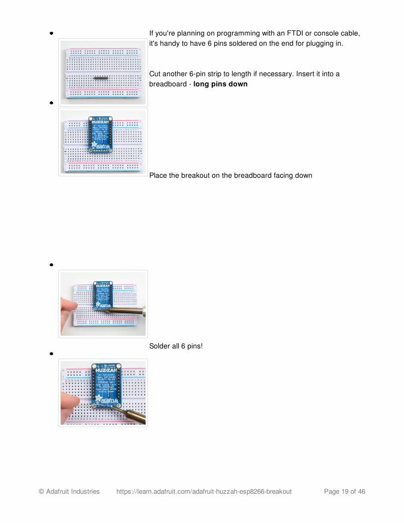
If you're planning on programming with an FTDI or console cable,it's handy to have 6 pins soldered on the end for plugging in.
Cut another 6-pin strip to length if necessary. Insert it into abreadboard - long pins down
Place the breakout on the breadboard facing down
Solder all 6 pins!
© Adafruit Industries https://learn.adafruit.com/adafruit-huzzah-esp8266-breakout Page 19 of 46
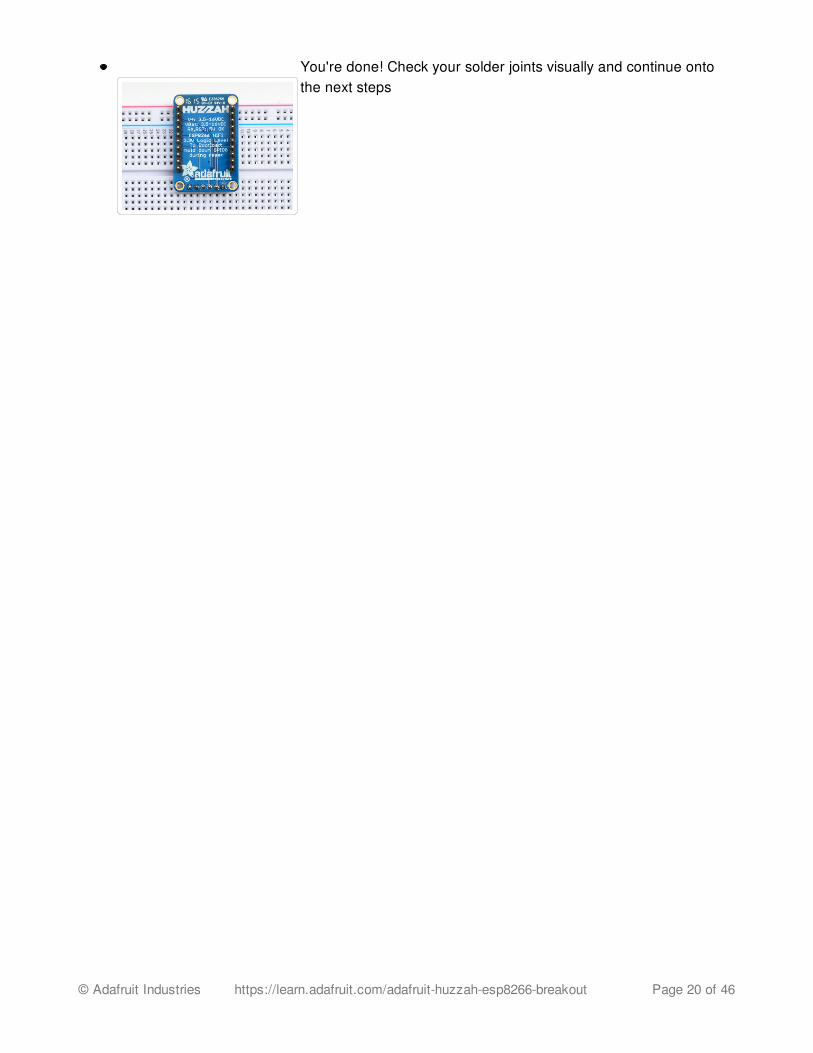
You're done! Check your solder joints visually and continue ontothe next steps
© Adafruit Industries https://learn.adafruit.com/adafruit-huzzah-esp8266-breakout Page 20 of 46
Using NodeMCU LuaEach HUZZAH ESP8266 breakout comes pre-programmed with NodeMCU's Lua interpretter. As ofthis writing, we ship with NodeMCU 0.9.5 build 20150318 powered by Lua 5.1.4 but it may be morerecent
The Lua interpretter runs on the ESP8266 and you can type in commands and read out the resultsover serial. A serial console cable is perfect for this! Use either an FTDI cable (http://adafru.it/dNN) orany console cable (http://adafru.it/954), you can use either 3V or 5V logic and power as there is levelshifting on the RX pin.
Don't forget to visit esp8266.com for the latest and greatest in ESP8266 news, software andgossip! (http://adafru.it/f1F)
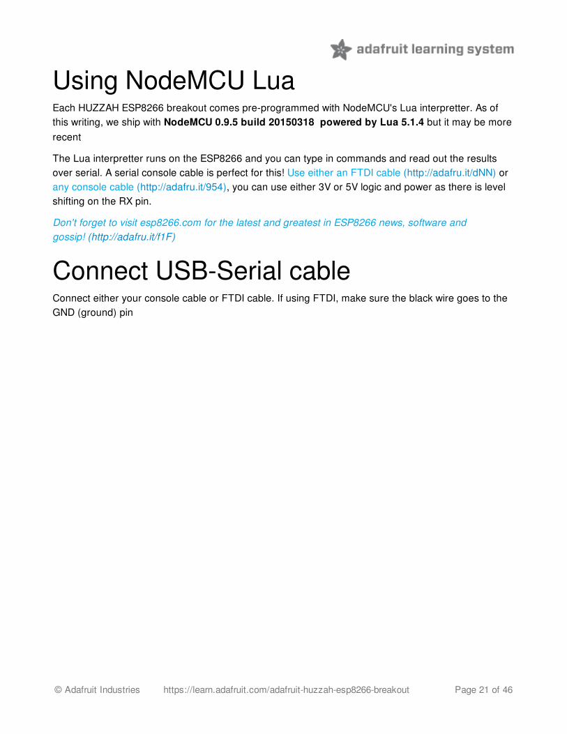
Connect USB-Serial cableConnect either your console cable or FTDI cable. If using FTDI, make sure the black wire goes to theGND (ground) pin
© Adafruit Industries https://learn.adafruit.com/adafruit-huzzah-esp8266-breakout Page 21 of 46

If using a console cable, connect the black wire to ground, red wire to V+, white wire to TX and greenwire to RX
© Adafruit Industries https://learn.adafruit.com/adafruit-huzzah-esp8266-breakout Page 22 of 46
You will see the red and blue onboard LED flicker when powered up, but they will not stay lit.
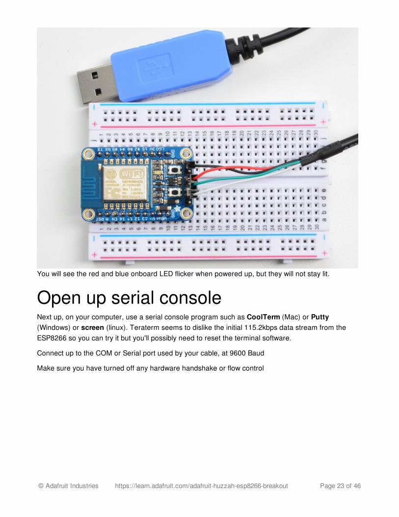
Open up serial consoleNext up, on your computer, use a serial console program such as CoolTerm (Mac) or Putty(Windows) or screen (linux). Teraterm seems to dislike the initial 115.2kbps data stream from theESP8266 so you can try it but you'll possibly need to reset the terminal software.
Connect up to the COM or Serial port used by your cable, at 9600 Baud
Make sure you have turned off any hardware handshake or flow control
© Adafruit Industries https://learn.adafruit.com/adafruit-huzzah-esp8266-breakout Page 23 of 46
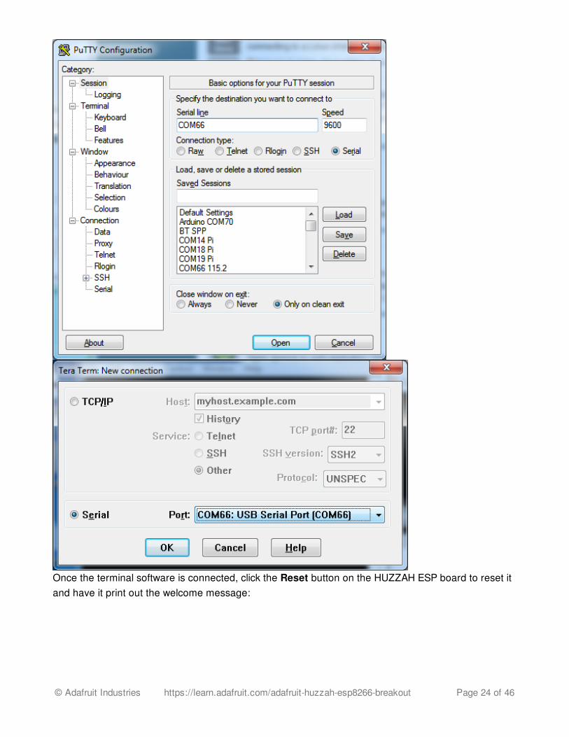
Once the terminal software is connected, click the Reset button on the HUZZAH ESP board to reset itand have it print out the welcome message:
© Adafruit Industries https://learn.adafruit.com/adafruit-huzzah-esp8266-breakout Page 24 of 46
If you don't get this message, first check that the red/blue leds flickered when you press the resetbutton. If they didnt, make sure the board is powered via V+ or Vbat. If they do flicker, make sureyou've got the right baud rate selected in the software (9600) and the RX/TX/GND pins connectedright
Hello world!Ok we can now turn on an LED. There is a red LED on each board, connected to GPIO #0
NodeMCU's pinouts are not the same as the Arduino/gcc pinouts. We print the Arduino pinoutson the board so watch out!
Rev A of this board has GPIO #4 and #5 swapped (the modules changed pinouts on us) so if#4/#5 aren't working for you, try swapping! We'll fix in the next PCB run
Pin Notes PCB/Arduino NodeMCU/Lua
No pullups! 0 3
2 4
3 9
© Adafruit Industries https://learn.adafruit.com/adafruit-huzzah-esp8266-breakout Page 25 of 46
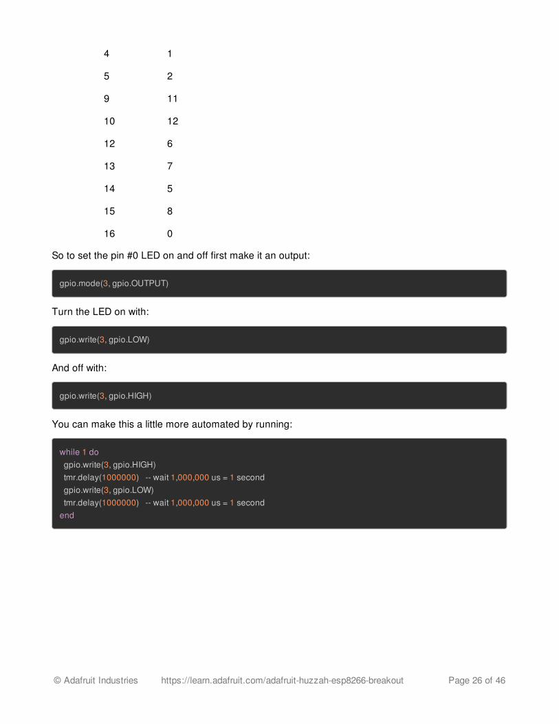
4 1
5 2
9 11
10 12
12 6
13 7
14 5
15 8
16 0
So to set the pin #0 LED on and off first make it an output:
gpio.mode(3, gpio.OUTPUT)
Turn the LED on with:
gpio.write(3, gpio.LOW)
And off with:
gpio.write(3, gpio.HIGH)
You can make this a little more automated by running:
while 1 do gpio.write(3, gpio.HIGH) tmr.delay(1000000) -- wait 1,000,000 us = 1 second gpio.write(3, gpio.LOW) tmr.delay(1000000) -- wait 1,000,000 us = 1 secondend
© Adafruit Industries https://learn.adafruit.com/adafruit-huzzah-esp8266-breakout Page 26 of 46
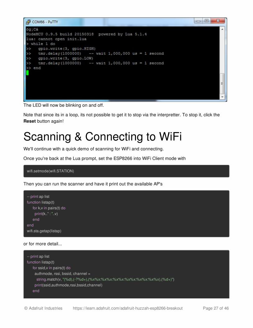
The LED will now be blinking on and off.
Note that since its in a loop, its not possible to get it to stop via the interpretter. To stop it, click theReset button again!
Scanning & Connecting to WiFiWe'll continue with a quick demo of scanning for WiFi and connecting.
Once you're back at the Lua prompt, set the ESP8266 into WiFi Client mode with
wifi.setmode(wifi.STATION)
Then you can run the scanner and have it print out the available AP's
-- print ap listfunction listap(t) for k,v in pairs(t) do print(k.." : "..v) endendwifi.sta.getap(listap)
or for more detail...
-- print ap listfunction listap(t) for ssid,v in pairs(t) do authmode, rssi, bssid, channel = string.match(v, "(%d),(-?%d+),(%x%x:%x%x:%x%x:%x%x:%x%x:%x%x),(%d+)") print(ssid,authmode,rssi,bssid,channel) end
© Adafruit Industries https://learn.adafruit.com/adafruit-huzzah-esp8266-breakout Page 27 of 46
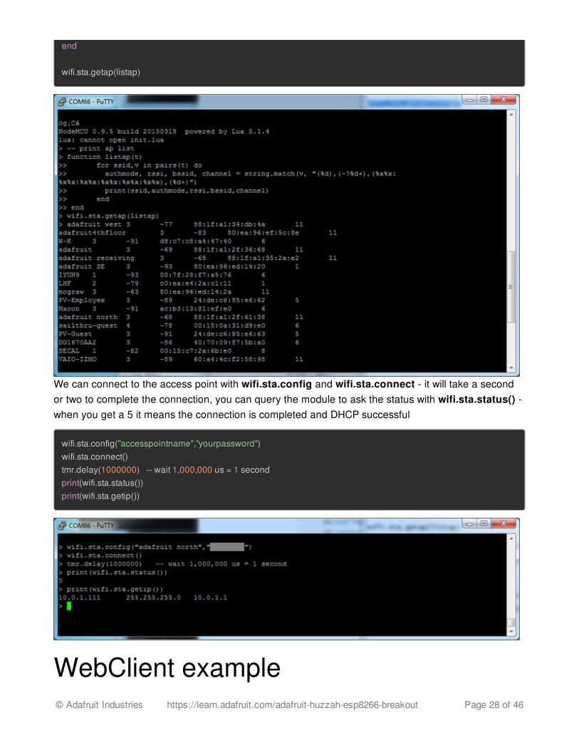
end wifi.sta.getap(listap)
We can connect to the access point with wifi.sta.config and wifi.sta.connect - it will take a secondor two to complete the connection, you can query the module to ask the status with wifi.sta.status() -when you get a 5 it means the connection is completed and DHCP successful
wifi.sta.config("accesspointname","yourpassword")wifi.sta.connect()tmr.delay(1000000) -- wait 1,000,000 us = 1 secondprint(wifi.sta.status())print(wifi.sta.getip())
WebClient example© Adafruit Industries https://learn.adafruit.com/adafruit-huzzah-esp8266-breakout Page 28 of 46
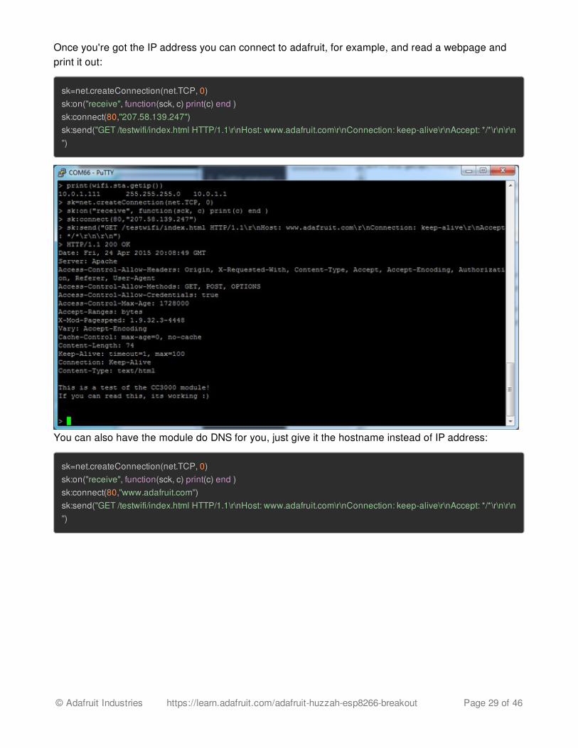
WebClient exampleOnce you're got the IP address you can connect to adafruit, for example, and read a webpage andprint it out:
sk=net.createConnection(net.TCP, 0)sk:on("receive", function(sck, c) print(c) end )sk:connect(80,"207.58.139.247")sk:send("GET /testwifi/index.html HTTP/1.1\r\nHost: www.adafruit.com\r\nConnection: keep-alive\r\nAccept: */*\r\n\r\n")
You can also have the module do DNS for you, just give it the hostname instead of IP address:
sk=net.createConnection(net.TCP, 0)sk:on("receive", function(sck, c) print(c) end )sk:connect(80,"www.adafruit.com")sk:send("GET /testwifi/index.html HTTP/1.1\r\nHost: www.adafruit.com\r\nConnection: keep-alive\r\nAccept: */*\r\n\r\n")
© Adafruit Industries https://learn.adafruit.com/adafruit-huzzah-esp8266-breakout Page 29 of 46
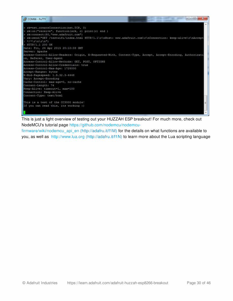
This is just a light overview of testing out your HUZZAH ESP breakout! For much more, check outNodeMCU's tutorial page https://github.com/nodemcu/nodemcu-firmware/wiki/nodemcu_api_en (http://adafru.it/f1M) for the details on what functions are available toyou, as well as http://www.lua.org (http://adafru.it/f1N) to learn more about the Lua scripting language
© Adafruit Industries https://learn.adafruit.com/adafruit-huzzah-esp8266-breakout Page 30 of 46
Using Arduino IDEWhile the HUZZAH ESP8266 breakout comes pre-programmed with NodeMCU's Lua interpretter, youdon't have to use it! Instead, you can use the Arduino IDE which may be more familar. This will writedirectly to the firmware, erasing the NodeMCU firmware, so if you want to go back to Lua, use theflasher to re-install it (http://adafru.it/f1O)
In order to upload code to the ESP8266 and use the serial console, you will need a USB to serialconverter! Use either an FTDI cable (http://adafru.it/dNN) or any console cable (http://adafru.it/954),you can use either 3V or 5V logic and power as there is level shifting on the RX pin.
Don't forget to visit esp8266.com for the latest and greatest in ESP8266 news, software andgossip! (http://adafru.it/f1F)
PL2303 USB console cables seem to only work with Windows computers for some reason. Macusers, we suggest FTDI cables!
Connect USB-Serial cableConnect either your console cable or FTDI cable. If using FTDI, make sure the black wire goes to theGND (ground) pin
© Adafruit Industries https://learn.adafruit.com/adafruit-huzzah-esp8266-breakout Page 31 of 46
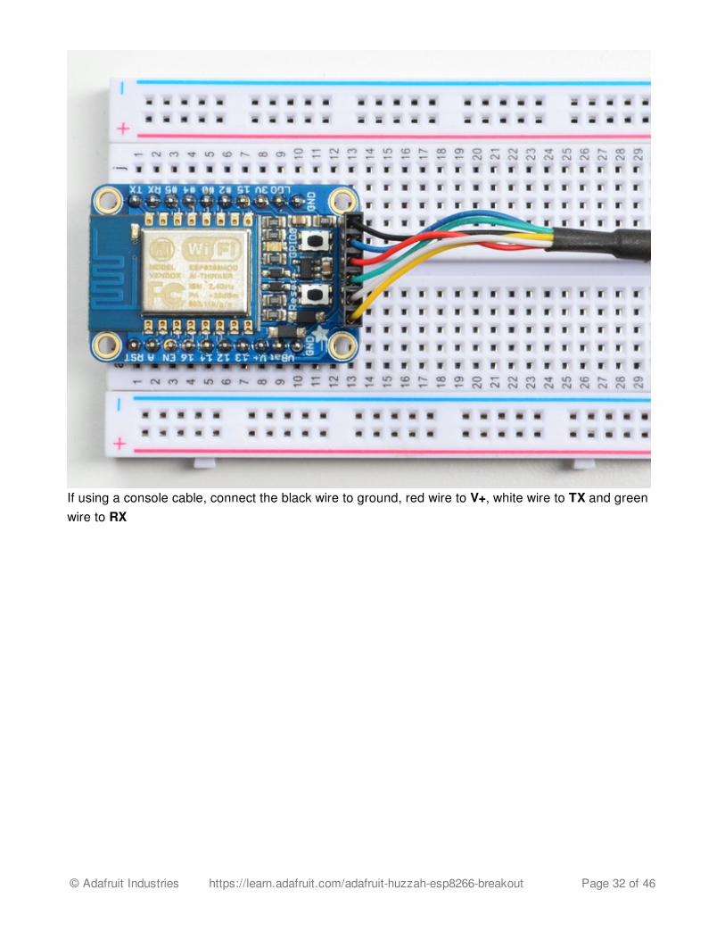
If using a console cable, connect the black wire to ground, red wire to V+, white wire to TX and greenwire to RX
© Adafruit Industries https://learn.adafruit.com/adafruit-huzzah-esp8266-breakout Page 32 of 46
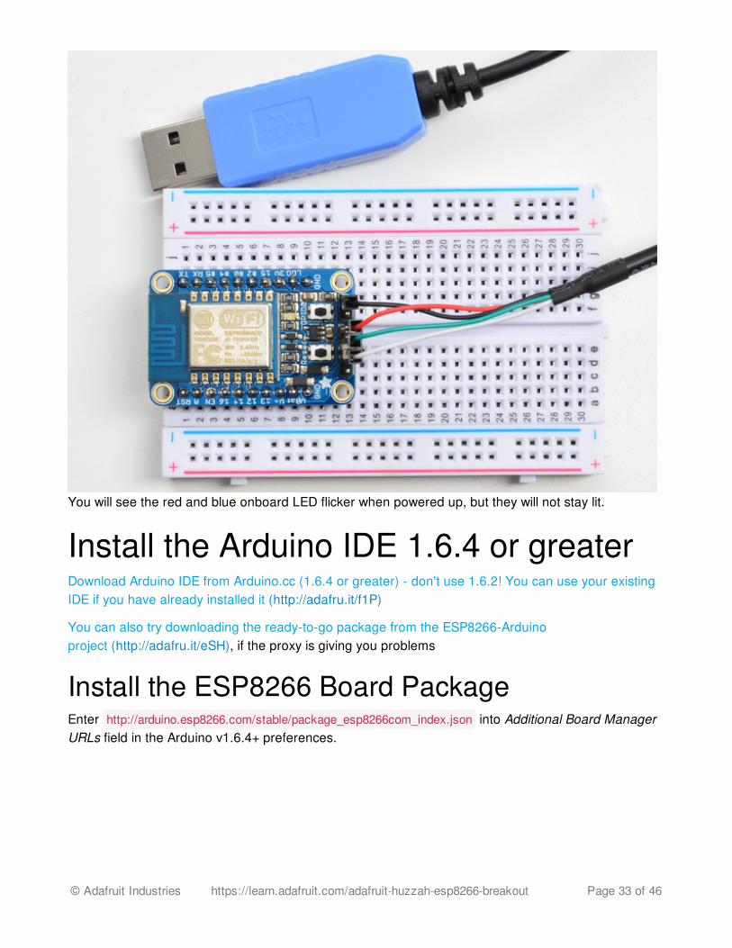
You will see the red and blue onboard LED flicker when powered up, but they will not stay lit.
Install the Arduino IDE 1.6.4 or greaterDownload Arduino IDE from Arduino.cc (1.6.4 or greater) - don't use 1.6.2! You can use your existingIDE if you have already installed it (http://adafru.it/f1P)
You can also try downloading the ready-to-go package from the ESP8266-Arduinoproject (http://adafru.it/eSH), if the proxy is giving you problems
Install the ESP8266 Board PackageEnter http://arduino.esp8266.com/stable/package_esp8266com_index.json into Additional Board ManagerURLs field in the Arduino v1.6.4+ preferences.
© Adafruit Industries https://learn.adafruit.com/adafruit-huzzah-esp8266-breakout Page 33 of 46
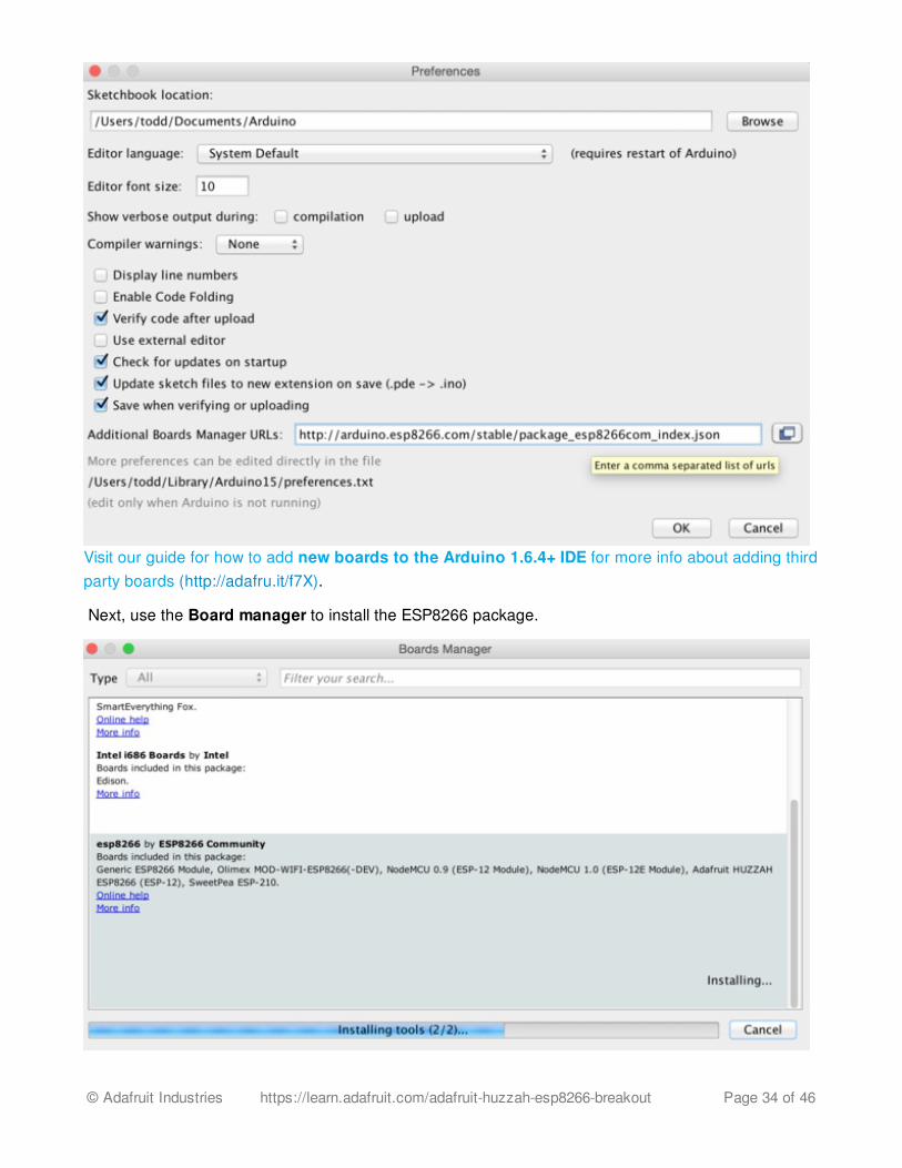
Visit our guide for how to add new boards to the Arduino 1.6.4+ IDE for more info about adding thirdparty boards (http://adafru.it/f7X).
Next, use the Board manager to install the ESP8266 package.
© Adafruit Industries https://learn.adafruit.com/adafruit-huzzah-esp8266-breakout Page 34 of 46
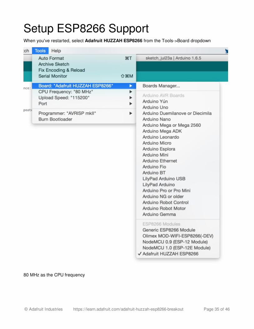
Setup ESP8266 SupportWhen you've restarted, select Adafruit HUZZAH ESP8266 from the Tools->Board dropdown
80 MHz as the CPU frequency
© Adafruit Industries https://learn.adafruit.com/adafruit-huzzah-esp8266-breakout Page 35 of 46
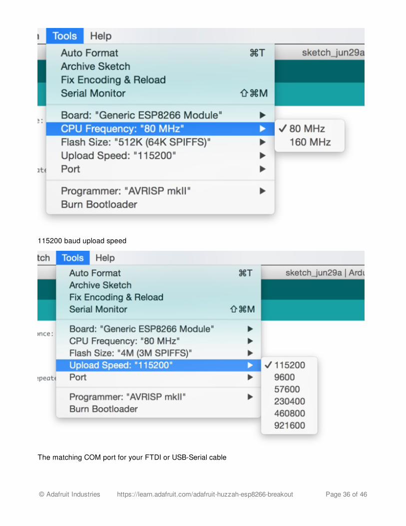
115200 baud upload speed
The matching COM port for your FTDI or USB-Serial cable
© Adafruit Industries https://learn.adafruit.com/adafruit-huzzah-esp8266-breakout Page 36 of 46
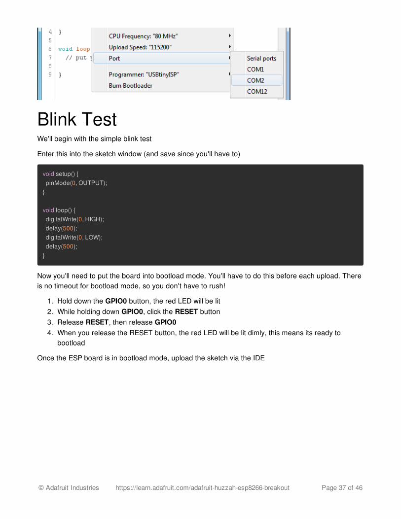
Blink TestWe'll begin with the simple blink test
Enter this into the sketch window (and save since you'll have to)
void setup() { pinMode(0, OUTPUT);}
void loop() { digitalWrite(0, HIGH); delay(500); digitalWrite(0, LOW); delay(500);}
Now you'll need to put the board into bootload mode. You'll have to do this before each upload. Thereis no timeout for bootload mode, so you don't have to rush!
1. Hold down the GPIO0 button, the red LED will be lit2. While holding down GPIO0, click the RESET button3. Release RESET, then release GPIO04. When you release the RESET button, the red LED will be lit dimly, this means its ready to
bootload
Once the ESP board is in bootload mode, upload the sketch via the IDE
© Adafruit Industries https://learn.adafruit.com/adafruit-huzzah-esp8266-breakout Page 37 of 46
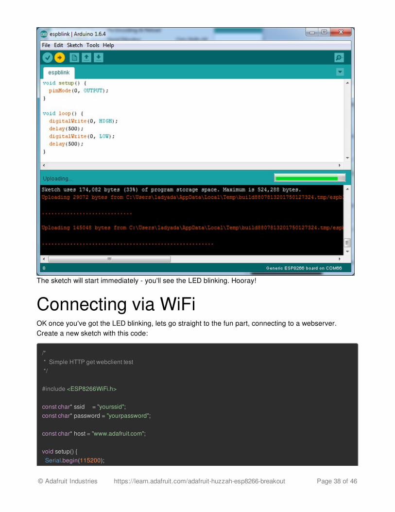
The sketch will start immediately - you'll see the LED blinking. Hooray!
Connecting via WiFiOK once you've got the LED blinking, lets go straight to the fun part, connecting to a webserver.Create a new sketch with this code:
/* * Simple HTTP get webclient test */
#include <ESP8266WiFi.h>
const char* ssid = "yourssid";const char* password = "yourpassword";
const char* host = "www.adafruit.com";
void setup() { Serial.begin(115200);
© Adafruit Industries https://learn.adafruit.com/adafruit-huzzah-esp8266-breakout Page 38 of 46
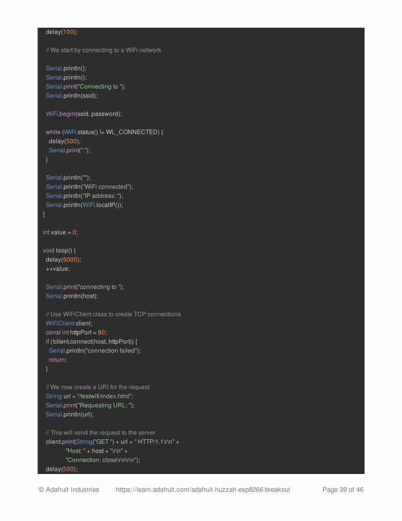
delay(100);
// We start by connecting to a WiFi network
Serial.println(); Serial.println(); Serial.print("Connecting to "); Serial.println(ssid); WiFi.begin(ssid, password); while (WiFi.status() != WL_CONNECTED) { delay(500); Serial.print("."); }
Serial.println(""); Serial.println("WiFi connected"); Serial.println("IP address: "); Serial.println(WiFi.localIP());}
int value = 0;
void loop() { delay(5000); ++value;
Serial.print("connecting to "); Serial.println(host); // Use WiFiClient class to create TCP connections WiFiClient client; const int httpPort = 80; if (!client.connect(host, httpPort)) { Serial.println("connection failed"); return; } // We now create a URI for the request String url = "/testwifi/index.html"; Serial.print("Requesting URL: "); Serial.println(url); // This will send the request to the server client.print(String("GET ") + url + " HTTP/1.1\r\n" + "Host: " + host + "\r\n" + "Connection: close\r\n\r\n"); delay(500);
© Adafruit Industries https://learn.adafruit.com/adafruit-huzzah-esp8266-breakout Page 39 of 46
// Read all the lines of the reply from server and print them to Serial while(client.available()){ String line = client.readStringUntil('\r'); Serial.print(line); } Serial.println(); Serial.println("closing connection");}
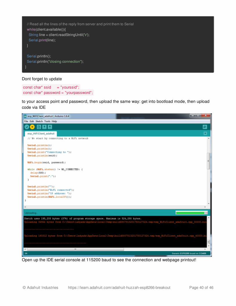
Dont forget to update
const char* ssid = "yourssid";const char* password = "yourpassword";
to your access point and password, then upload the same way: get into bootload mode, then uploadcode via IDE
Open up the IDE serial console at 115200 baud to see the connection and webpage printout!
© Adafruit Industries https://learn.adafruit.com/adafruit-huzzah-esp8266-breakout Page 40 of 46
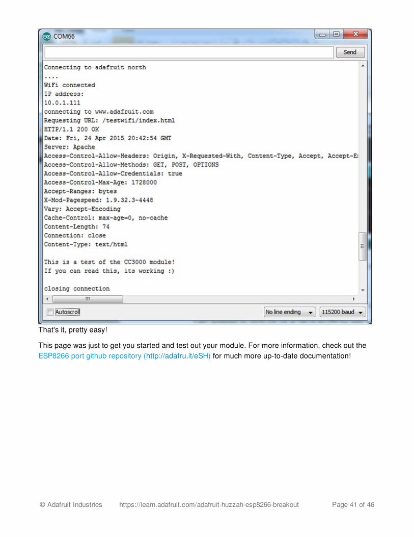
That's it, pretty easy!
This page was just to get you started and test out your module. For more information, check out theESP8266 port github repository (http://adafru.it/eSH) for much more up-to-date documentation!
© Adafruit Industries https://learn.adafruit.com/adafruit-huzzah-esp8266-breakout Page 41 of 46
Other OptionsYou can also try using embedXcode (http://adafru.it/f5J) which has a template for the ESP8266with Xcodeesp-open-sdk (http://adafru.it/f5K) is a toolchain that will let you progam the ESP8266 processordirectly (more info at the esp8266.com wiki (http://adafru.it/f5L))
© Adafruit Industries https://learn.adafruit.com/adafruit-huzzah-esp8266-breakout Page 42 of 46
Downloads
More info about the ESP8266ESP8266 specification sheet (http://adafru.it/f1E)SPX3819 3.3V linear regulator on board (http://adafru.it/f4z)FCC test report (http://adafru.it/f1S) for the module used on this breakoutCE test report for the module used on this breakout (http://adafru.it/f1U)Huuuuge amount of information on http://www.esp8266.com/ (http://adafru.it/f1F) communityforum!NodeMCU (Lua for ESP8266) webpage (http://adafru.it/f1G) with examples and documentationon the Lua frameworkArduino IDE support for ESP8266 (http://adafru.it/eSH)
Don't forget to visit esp8266.com for the latest and greatest in ESP8266 news, software andgossip! (http://adafru.it/f1F)
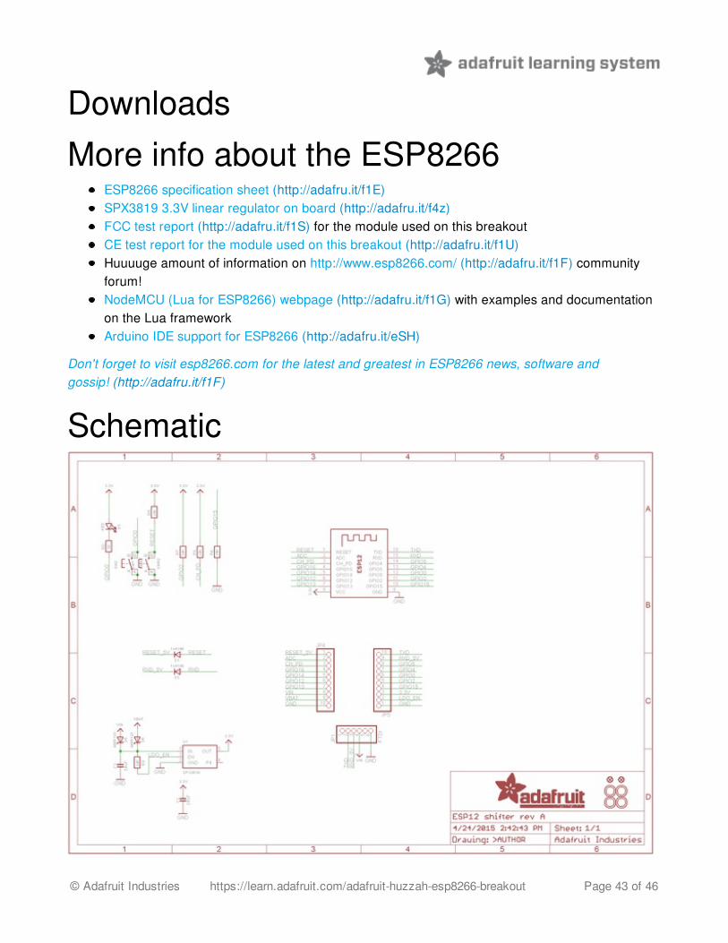
Schematic
© Adafruit Industries https://learn.adafruit.com/adafruit-huzzah-esp8266-breakout Page 43 of 46
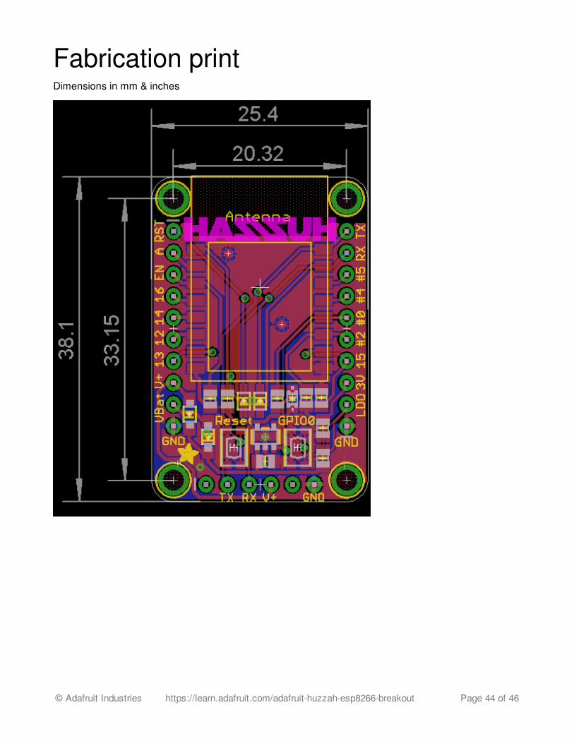
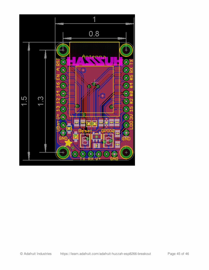
Fabrication printDimensions in mm & inches
© Adafruit Industries https://learn.adafruit.com/adafruit-huzzah-esp8266-breakout Page 44 of 46
© Adafruit Industries https://learn.adafruit.com/adafruit-huzzah-esp8266-breakout Page 45 of 46
F.A.Q.When I connect stuff to some of the pins, the Huzzah stops working. Whats up with that?The ESP8266 uses some of the pins as 'boot mode' pins so on boot they must be set to certainvalues:
CH_PD should be always pulled high (it will disable the entire module if low)RST should be always pulled high (it will disable the entire module if low)GPIO 0 sets whether the bootloader is active, it must be pulled HIGH during power up/reset forthe user program to run. If its pulled LOW, it will activate the bootloader. The built-in red LED on#0 pulls it upGPIO 2 must be pulled high on power up/reset.GPIO 15 must be pulled low on power up/reset.
My Huzzah board keeps crashing and resetting, whats up with that?The most common reason for crashes is power failure. Make sure you're powering the Huzzah with agood ~5V power supply, and if you're using a USB-Serial cable, that its plugged into the mainboard ofyour computer or through a powered hub!
I'm having difficulties uploading to the HUZZAH with the Arduino IDEMake sure you're using a good quality USB/Serial cable. Install the official drivers for that cable too!We've also noticed that PL2303-based cables don't work on Macs for some reason. FTDI or CP210xbased chipsets work best
© Adafruit Industries Last Updated: 2016-02-07 10:00:48 PM EST Page 46 of 46