Embed Size (px)
Citation preview
5773 841 GB 7/2014
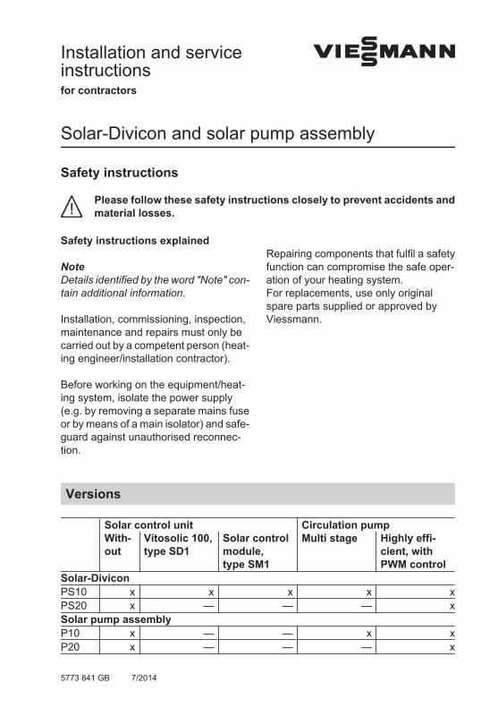
Installation and serviceinstructionsfor contractors
VIESMANN
Solar-Divicon and solar pump assembly
Safety instructions
Please follow these safety instructions closely to prevent accidents andmaterial losses.
Safety instructions explained
NoteDetails identified by the word "Note" con-tain additional information.
Installation, commissioning, inspection,maintenance and repairs must only becarried out by a competent person (heat-ing engineer/installation contractor).
Before working on the equipment/heat-ing system, isolate the power supply(e.g. by removing a separate mains fuseor by means of a main isolator) and safe-guard against unauthorised reconnec-tion.
Repairing components that fulfil a safetyfunction can compromise the safe oper-ation of your heating system. For replacements, use only originalspare parts supplied or approved byViessmann.
Versions
Solar control unit Circulation pump With-
outVitosolic 100,type SD1
Solar controlmodule,type SM1
Multi stage Highly effi-cient, withPWM control
Solar-DiviconPS10 x x x x xPS20 x — — — xSolar pump assemblyP10 x — — x xP20 x — — — x
2
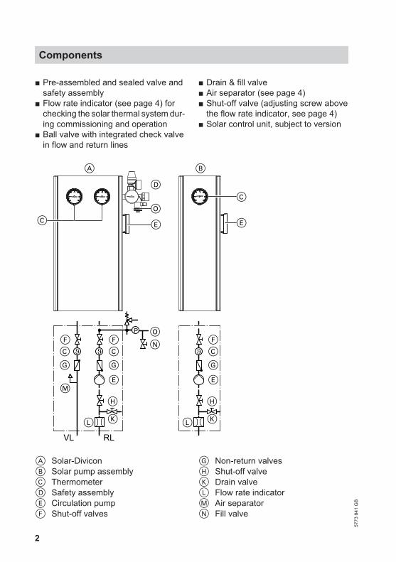
■ Pre-assembled and sealed valve andsafety assembly
■ Flow rate indicator (see page 4) forchecking the solar thermal system dur-ing commissioning and operation
■ Ball valve with integrated check valvein flow and return lines
■ Drain & fill valve■ Air separator (see page 4)■ Shut-off valve (adjusting screw above
the flow rate indicator, see page 4)■ Solar control unit, subject to version
E
A
E
D
C
P
N
K
F
H
F
M
C
G
E
L
C
G
K
F
H
C
G
E
L
B
VL RL
CO
O
A Solar-DiviconB Solar pump assemblyC ThermometerD Safety assemblyE Circulation pumpF Shut-off valves
G Non-return valvesH Shut-off valveK Drain valveL Flow rate indicatorM Air separatorN Fill valve
Components
5773
841
GB
3
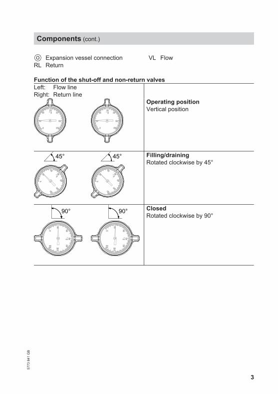
O Expansion vessel connectionRL Return
VL Flow
Function of the shut-off and non-return valvesLeft: Flow lineRight: Return line
Operating positionVertical position
45° 45° Filling/drainingRotated clockwise by 45°
90° 90° ClosedRotated clockwise by 90°
Components (cont.)
5773
841
GB
4
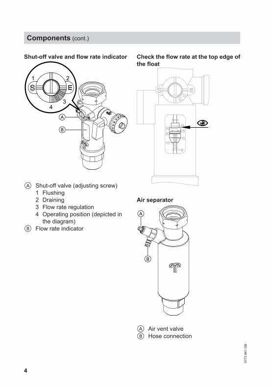
Shut-off valve and flow rate indicator
A
B
1 2
43
A Shut-off valve (adjusting screw)1 Flushing2 Draining3 Flow rate regulation4 Operating position (depicted in
the diagram)B Flow rate indicator
Check the flow rate at the top edge ofthe float
20
5
15
25
10
3530
l/min
Air separator
B
A
A Air vent valveB Hose connection
Components (cont.)
5773
841
GB
5
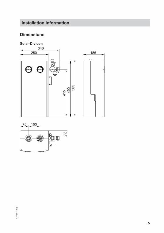
Dimensions
Solar-Divicon
250346
186
415 49
0 505
66
75 100
Installation information57
73 8
41 G
B
6
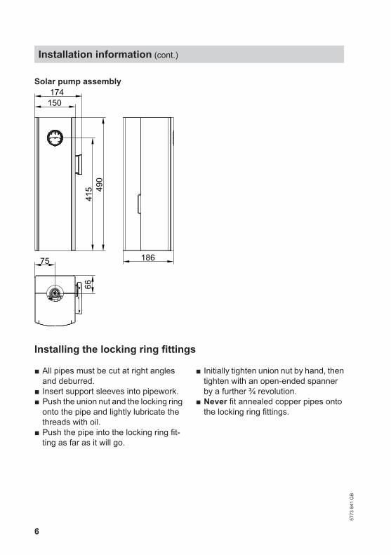
Solar pump assembly
150174
415 49
0
18675
66
Installing the locking ring fittings
■ All pipes must be cut at right anglesand deburred.
■ Insert support sleeves into pipework.■ Push the union nut and the locking ring
onto the pipe and lightly lubricate thethreads with oil.
■ Push the pipe into the locking ring fit-ting as far as it will go.
■ Initially tighten union nut by hand, thentighten with an open-ended spannerby a further ¾ revolution.
■ Never fit annealed copper pipes ontothe locking ring fittings.
Installation information (cont.)
5773
841
GB
7
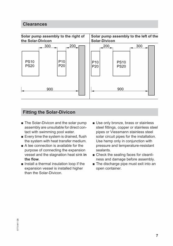
Solar pump assembly to the right ofthe Solar-Divicon
Solar pump assembly to the left of theSolar-Divicon
PS10PS20
P10P20
300
900
200
PS10PS20
P10P20
900
200 300
Fitting the Solar-Divicon
■ The Solar-Divicon and the solar pumpassembly are unsuitable for direct con-tact with swimming pool water.
■ Every time the system is drained, flushthe system with heat transfer medium.
■ A tee connection is available for thepurpose of connecting the expansionvessel and the stagnation heat sink inthe flow.
■ Install a thermal insulation loop if theexpansion vessel is installed higherthan the Solar-Divicon.
■ Use only bronze, brass or stainlesssteel fittings, copper or stainless steelpipes or Viessmann stainless steelsolar circuit pipes for the installation.Use hemp only in conjunction withpressure and temperature-resistantsealants.
■ Check the sealing faces for cleanli-ness and damage before assembly.
■ The discharge pipe must exit into anopen container.
Clearances57
73 8
41 G
B
8
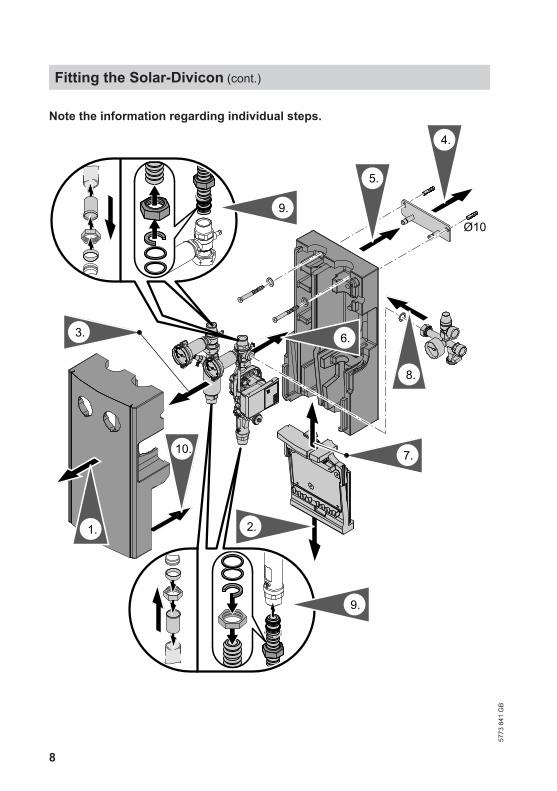
Note the information regarding individual steps.
Ø10
8.
5.
2.
7.
1.
3. 6.
10.
4.
9.
9.
Fitting the Solar-Divicon (cont.)
5773
841
GB
9
Information on step 1:After you have removed the upper insu-lation shell, remove the transport protec-tion cardboard.
Information on step 3:Remove the flow and return lines tomake installation easier.If you are installing a Solar-Divicon, typePS20, remove the spring clip beforeremoving the flow and return lines.
Information on step 9:Versions:■ Installation with copper pipes
Insert the support sleeves into thesolar circuit pipes and secure withvalve connections.
■ Installation with stainless steelsolar circuit pipeTrim and deburr in the valley of thecorrugation; do not damage the peakof the corrugation.Fit the union nut, half washer (in the5th valley) and O-rings (in the 1st and3rd valley).
Information on the Solar-Divicon,type PS10 with solar control unitFor maintenance and service work, thesolar control unit can be hooked into theside of the circulation pump.
Electrical connections
■ Version with solar control unit:The circulation pump is connected tothe solar control unit at the factory.See the installation and serviceinstructions for further connections.
■ Version without solar control unit:Route the connecting cable for the cir-culation pump downwards through thecable trunking and connect it to thesolar control unit.See the installation and serviceinstructions for further connections.
Fitting the Solar-Divicon (cont.)
5773
841
GB
10
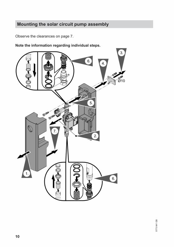
Observe the clearances on page 7.
Note the information regarding individual steps.
Ø10
1.
4.
7.
3.
2.
5.
6.
6.
Mounting the solar circuit pump assembly
5773
841
GB
11
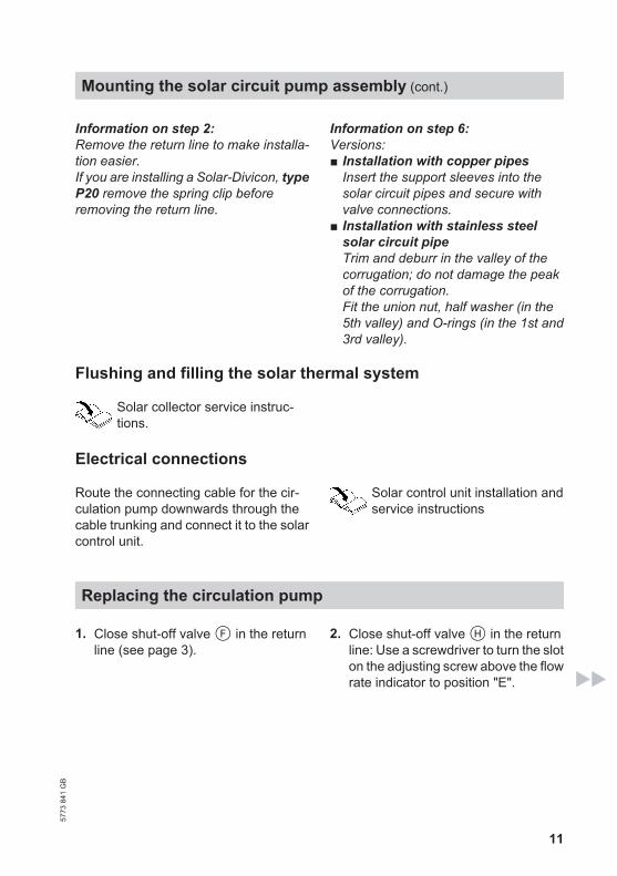
Information on step 2:Remove the return line to make installa-tion easier.If you are installing a Solar-Divicon, typeP20 remove the spring clip beforeremoving the return line.
Information on step 6:Versions:■ Installation with copper pipes
Insert the support sleeves into thesolar circuit pipes and secure withvalve connections.
■ Installation with stainless steelsolar circuit pipeTrim and deburr in the valley of thecorrugation; do not damage the peakof the corrugation.Fit the union nut, half washer (in the5th valley) and O-rings (in the 1st and3rd valley).
Flushing and filling the solar thermal system
Solar collector service instruc-tions.
Electrical connections
Route the connecting cable for the cir-culation pump downwards through thecable trunking and connect it to the solarcontrol unit.
Solar control unit installation andservice instructions
Replacing the circulation pump
1. Close shut-off valve F in the returnline (see page 3).
2. Close shut-off valve H in the returnline: Use a screwdriver to turn the sloton the adjusting screw above the flowrate indicator to position "E".
Mounting the solar circuit pump assembly (cont.)
5773
841
GB
12
K
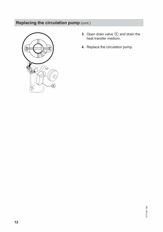
3. Open drain valve K and drain theheat transfer medium.
4. Replace the circulation pump.
Replacing the circulation pump (cont.)
5773
841
GB
13
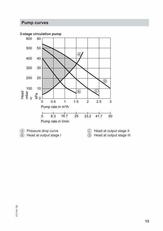
3-stage circulation pump
0 1 2 3Pump rate in m³/h
Hea
d
0
10
20
30
40
D
50
60
0.5 1.5 2.5
A
0 16.7 33.2 508.3 25 41.7Pump rate in l/min
CB
kPa
mba
r
0
100
200
300
400
500
600
A Pressure drop curveB Head at output stage I
C Head at output stage IID Head at output stage III
Pump curves57
73 8
41 G
B
14
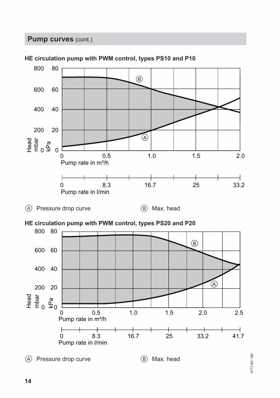
HE circulation pump with PWM control, types PS10 and P10
0 0.5 1.0 1.5Pump rate in m³/h
Hea
d
0
20
40
60
80
2.0
A
B
Pump rate in l/min0 8.3 16.7 25 33.2
kPa
0
200
400
600
800
mba
r
A Pressure drop curve B Max. head
HE circulation pump with PWM control, types PS20 and P20
Pump rate in m³/h
Hea
d
2.0
Pump rate in l/min0 8.3 16.7 25 33.2
0 0.5 1.0 1.50
20
40
60
80
2.5
41.7
200
400
600
800
kPa
0mba
r
A
B
A Pressure drop curve B Max. head
Pump curves (cont.)
5773
841
GB
15
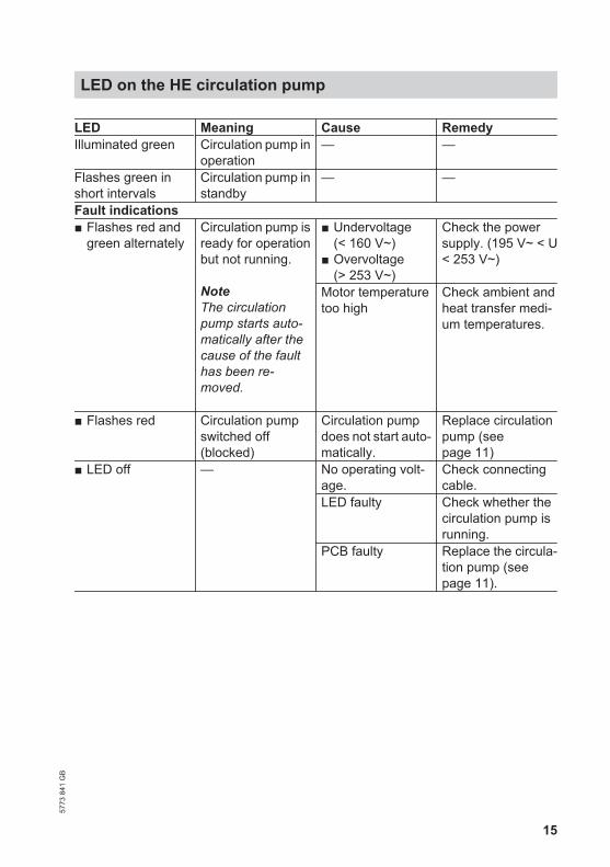
LED Meaning Cause RemedyIlluminated green Circulation pump in
operation— —
Flashes green inshort intervals
Circulation pump instandby
— —
Fault indications■ Flashes red and
green alternatelyCirculation pump isready for operationbut not running.
NoteThe circulationpump starts auto-matically after thecause of the faulthas been re-moved.
■ Undervoltage(< 160 V~)
■ Overvoltage(> 253 V~)
Check the powersupply. (195 V~ < U< 253 V~)
Motor temperaturetoo high
Check ambient andheat transfer medi-um temperatures.
■ Flashes red Circulation pumpswitched off(blocked)
Circulation pumpdoes not start auto-matically.
Replace circulationpump (seepage 11)
■ LED off — No operating volt-age.
Check connectingcable.
LED faulty Check whether thecirculation pump isrunning.
PCB faulty Replace the circula-tion pump (seepage 11).
LED on the HE circulation pump57
73 8
41 G
B
16
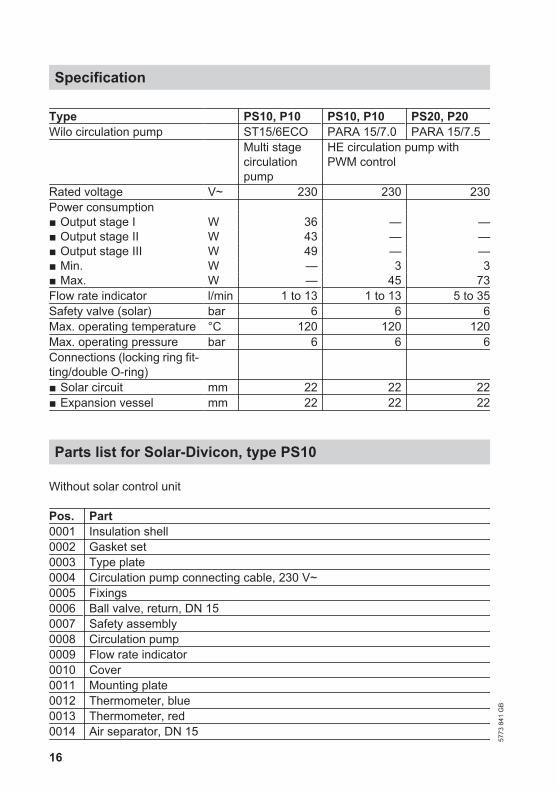
Type PS10, P10 PS10, P10 PS20, P20Wilo circulation pump ST15/6ECO PARA 15/7.0 PARA 15/7.5 Multi stage
circulationpump
HE circulation pump withPWM control
Rated voltage V~ 230 230 230Power consumption ■ Output stage I W 36 — —■ Output stage II W 43 — —■ Output stage III W 49 — —■ Min. W — 3 3■ Max. W — 45 73Flow rate indicator l/min 1 to 13 1 to 13 5 to 35Safety valve (solar) bar 6 6 6Max. operating temperature °C 120 120 120Max. operating pressure bar 6 6 6Connections (locking ring fit-ting/double O-ring)
■ Solar circuit mm 22 22 22■ Expansion vessel mm 22 22 22
Parts list for Solar-Divicon, type PS10
Without solar control unit
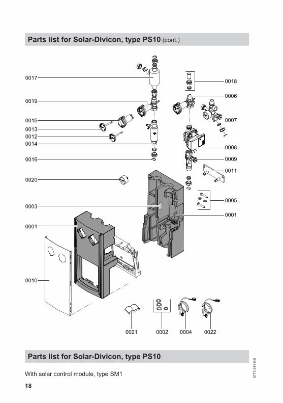
Pos. Part0001 Insulation shell0002 Gasket set0003 Type plate0004 Circulation pump connecting cable, 230 V~0005 Fixings0006 Ball valve, return, DN 150007 Safety assembly0008 Circulation pump0009 Flow rate indicator0010 Cover0011 Mounting plate0012 Thermometer, blue0013 Thermometer, red0014 Air separator, DN 15
Specification
5773
841
GB
17
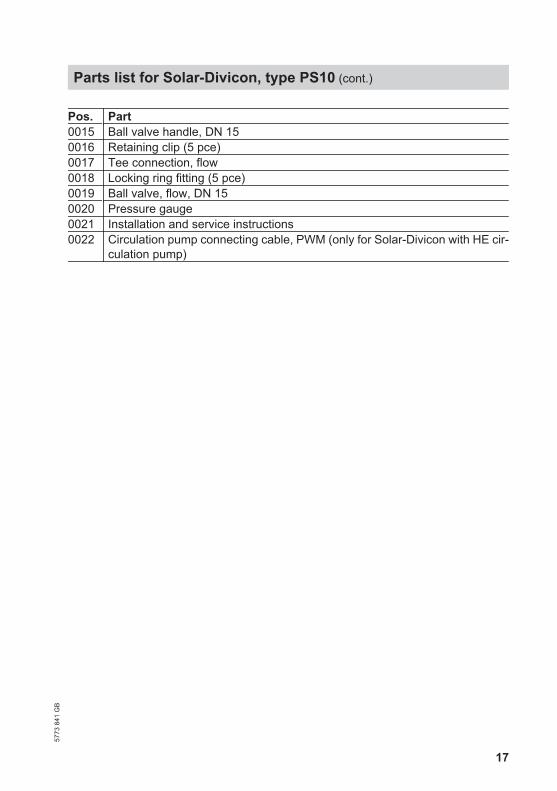
Pos. Part0015 Ball valve handle, DN 150016 Retaining clip (5 pce)0017 Tee connection, flow0018 Locking ring fitting (5 pce)0019 Ball valve, flow, DN 150020 Pressure gauge0021 Installation and service instructions0022 Circulation pump connecting cable, PWM (only for Solar-Divicon with HE cir-
culation pump)
Parts list for Solar-Divicon, type PS10 (cont.)
5773
841
GB
18
0002 0004
0001
0001
0005
0011
0008
0016
0017
001500130012
0019
0018
0006
0007
0010
0014
0020
0021 0022
0009
0003
Parts list for Solar-Divicon, type PS10
With solar control module, type SM1
Parts list for Solar-Divicon, type PS10 (cont.)
5773
841
GB
19
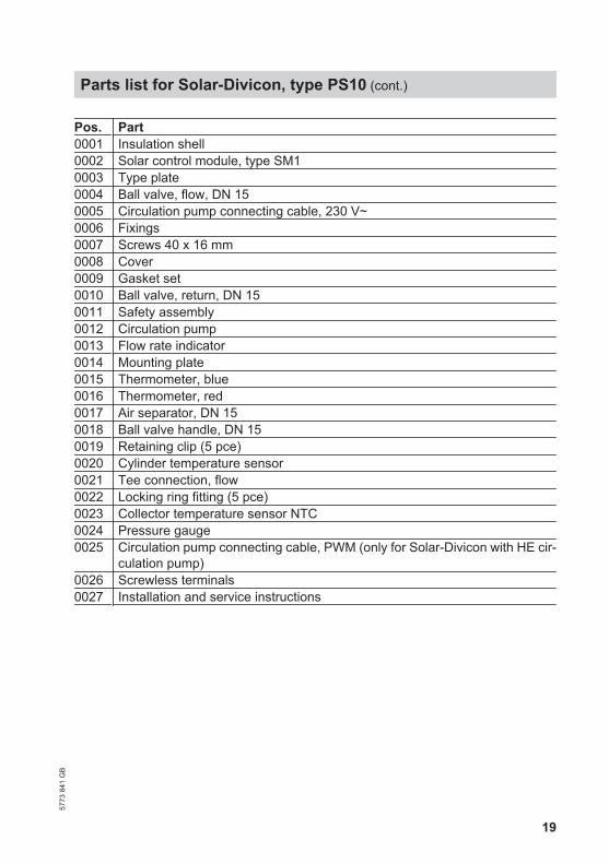
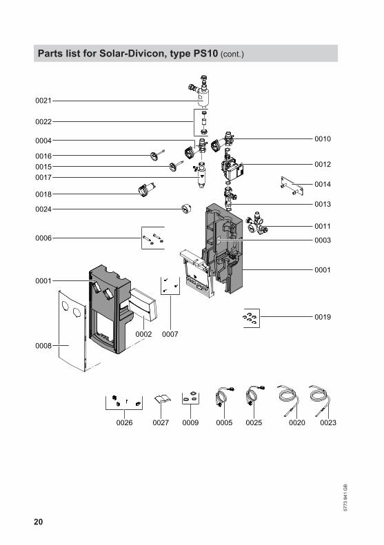
Pos. Part0001 Insulation shell0002 Solar control module, type SM10003 Type plate0004 Ball valve, flow, DN 150005 Circulation pump connecting cable, 230 V~0006 Fixings0007 Screws 40 x 16 mm0008 Cover0009 Gasket set0010 Ball valve, return, DN 150011 Safety assembly0012 Circulation pump0013 Flow rate indicator0014 Mounting plate0015 Thermometer, blue0016 Thermometer, red0017 Air separator, DN 150018 Ball valve handle, DN 150019 Retaining clip (5 pce)0020 Cylinder temperature sensor0021 Tee connection, flow0022 Locking ring fitting (5 pce)0023 Collector temperature sensor NTC0024 Pressure gauge0025 Circulation pump connecting cable, PWM (only for Solar-Divicon with HE cir-
culation pump)0026 Screwless terminals0027 Installation and service instructions
Parts list for Solar-Divicon, type PS10 (cont.)
5773
841
GB
20
0016
0017
00100004
0024
0026 0027
0019
0011
00070008
0006
0002
0022
0013
0012
0018
0015
002000250005
0001
0009
0021
0001
0014
0003
0023
Parts list for Solar-Divicon, type PS10 (cont.)
5773
841
GB
21
With Vitosolic 100, type SD1
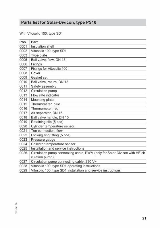
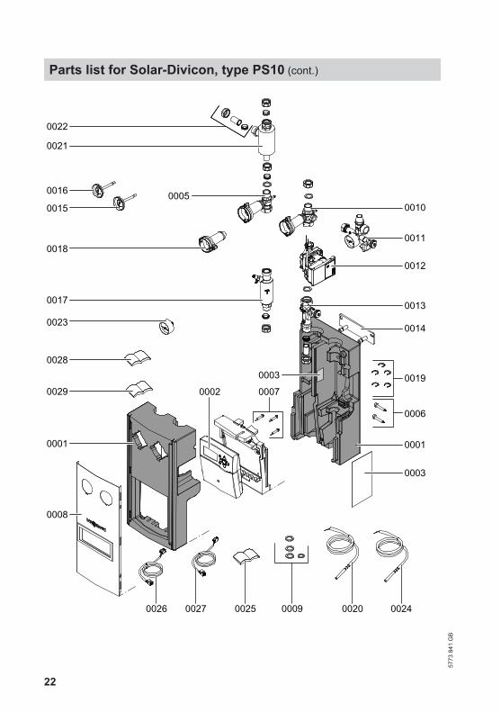
Pos. Part0001 Insulation shell0002 Vitosolic 100, type SD10003 Type plate0005 Ball valve, flow, DN 150006 Fixings0007 Fixings for Vitosolic 1000008 Cover0009 Gasket set0010 Ball valve, return, DN 150011 Safety assembly0012 Circulation pump0013 Flow rate indicator0014 Mounting plate0015 Thermometer, blue0016 Thermometer, red0017 Air separator, DN 150018 Ball valve handle, DN 150019 Retaining clip (5 pce)0020 Cylinder temperature sensor0021 Tee connection, flow0022 Locking ring fitting (5 pce)0023 Pressure gauge0024 Collector temperature sensor0025 Installation and service instructions0026 Circulation pump connecting cable, PWM (only for Solar-Divicon with HE cir-
culation pump)0027 Circulation pump connecting cable, 230 V~0028 Vitosolic 100, type SD1 operating instructions0029 Vitosolic 100, type SD1 installation and service instructions
Parts list for Solar-Divicon, type PS1057
73 8
41 G
B
22
0007
0001
0014
0021
0009
0003
0001
0002
0013
0023
0016
0015
0018
0022
0012
00100005
0017
0011
0008
0025
0029
0028
0026 0027 00240020
0006
00190003
Parts list for Solar-Divicon, type PS10 (cont.)
5773
841
GB
23
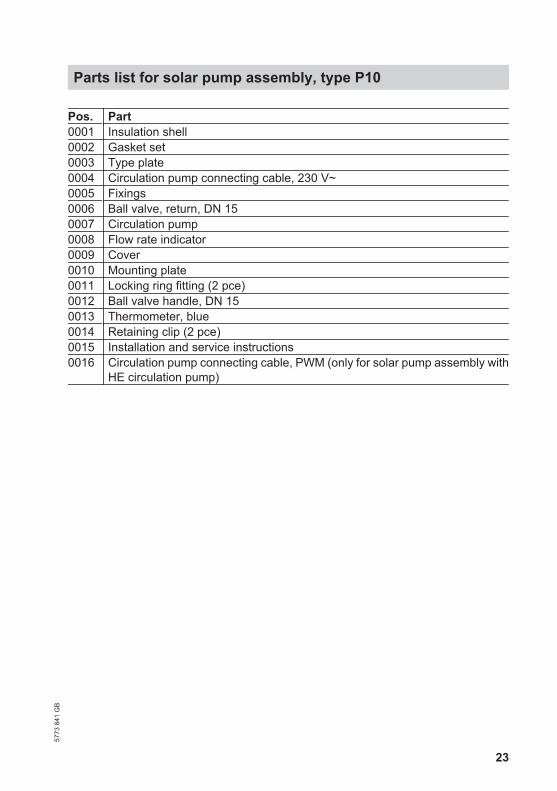
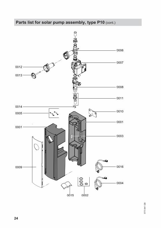
Pos. Part0001 Insulation shell0002 Gasket set0003 Type plate0004 Circulation pump connecting cable, 230 V~0005 Fixings0006 Ball valve, return, DN 150007 Circulation pump0008 Flow rate indicator0009 Cover0010 Mounting plate0011 Locking ring fitting (2 pce)0012 Ball valve handle, DN 150013 Thermometer, blue0014 Retaining clip (2 pce)0015 Installation and service instructions0016 Circulation pump connecting cable, PWM (only for solar pump assembly with
HE circulation pump)
Parts list for solar pump assembly, type P1057
73 8
41 G
B
24
0015 0002
0004
00160009
0001
0003
0005 0010
0008
0007
0006
0014
0011
0013
0001
0012
Parts list for solar pump assembly, type P10 (cont.)
5773
841
GB
25
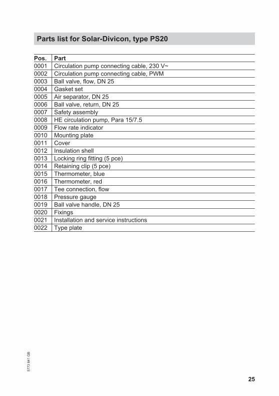
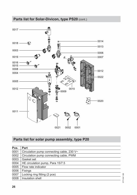
Pos. Part0001 Circulation pump connecting cable, 230 V~0002 Circulation pump connecting cable, PWM0003 Ball valve, flow, DN 250004 Gasket set0005 Air separator, DN 250006 Ball valve, return, DN 250007 Safety assembly0008 HE circulation pump, Para 15/7.50009 Flow rate indicator0010 Mounting plate0011 Cover0012 Insulation shell0013 Locking ring fitting (5 pce)0014 Retaining clip (5 pce)0015 Thermometer, blue0016 Thermometer, red0017 Tee connection, flow0018 Pressure gauge0019 Ball valve handle, DN 250020 Fixings0021 Installation and service instructions0022 Type plate
Parts list for Solar-Divicon, type PS2057
73 8
41 G
B
26
0011
0016
0005
0018
0017
0013
0014
0007
0012
00030006
0020
0012
000100020021
0019
000400080015
00090010
0022
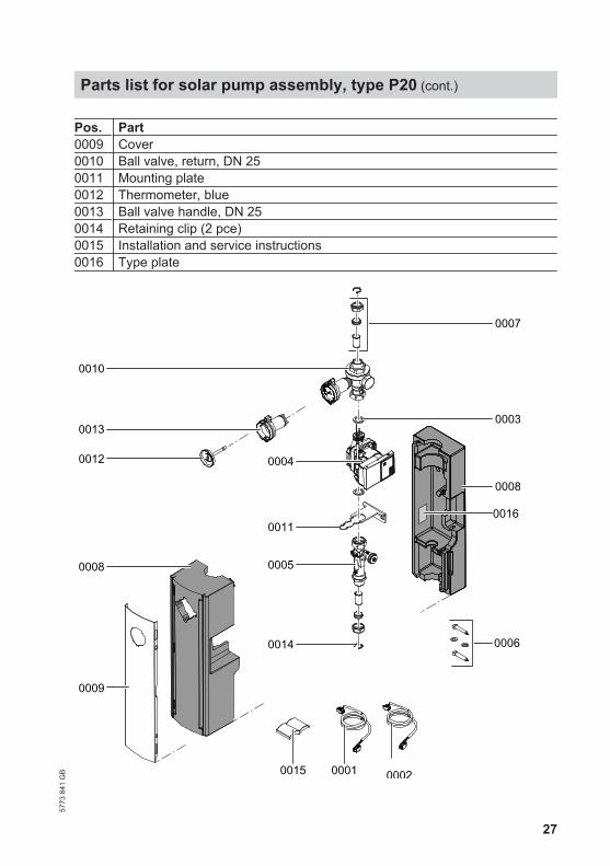
Parts list for solar pump assembly, type P20
Pos. Part0001 Circulation pump connecting cable, 230 V~0002 Circulation pump connecting cable, PWM0003 Gasket set0004 HE circulation pump, Para 15/7.50005 Flow rate indicator0006 Fixings0007 Locking ring fitting (2 pce)0008 Insulation shell
Parts list for Solar-Divicon, type PS20 (cont.)
5773
841
GB
27
Pos. Part0009 Cover0010 Ball valve, return, DN 250011 Mounting plate0012 Thermometer, blue0013 Ball valve handle, DN 250014 Retaining clip (2 pce)0015 Installation and service instructions0016 Type plate
0001
0005
0004
0014
0007
0003
0011
00020015
0016
0006
0008
0010
0013
0012
0008
0009
Parts list for solar pump assembly, type P20 (cont.)
5773
841
GB
28
Applicability
Serial No.:7511246 7511247 7511248 75112497511250 7511251 7511252 75112537514721 7514725
Viessmann LimitedHortonwood 30, TelfordShropshire, TF1 7YP, GBTelephone: +44 1952 675000Fax: +44 1952 675040E-mail: [email protected]
Viessmann Werke GmbH&Co KGD-35107 AllendorfTelephone: +49 6452 70-0Fax: +49 6452 70-2780www.viessmann.com
5773
841
GB
Sub
ject
to te
chni
cal m
odifi
catio
ns.