Embed Size (px)
Citation preview
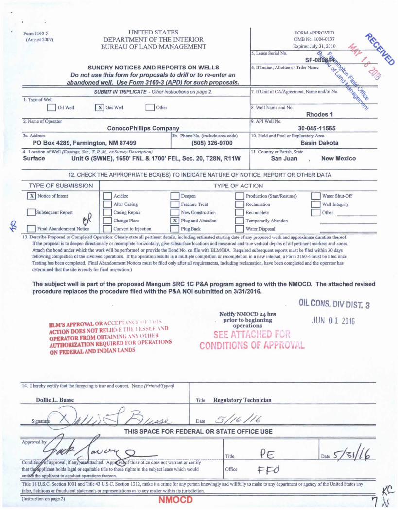
Form 3160-5 UNITED STATES
(August 2007) DEPARTMENT OF THE INTERIOR
BUREAU OF LAND MANAGEMENT
SUNDRY NOTICES AND REPORTS ON WELLS
Do not use this form for proposals to drill or to re-enter an abandoned well. Use Form 3160-3 (APD) for such proposals.
FORM APPROVED a
OMB No. 1004-0137Expires: July 31.2010 /£, Q
5. Lease Serial No. <£ ^SF-Oifa*^ /
6. If Indian, Allottee or Tribe Name ^ 3
%s %SUBMIT IN TRIPUCATE - Other instructions on page 2. 7. If Unit of CA/Agreement, Name and/or No.
V1. Type of Well
] Oil Well [x] Gas Well Q Other 8. Well Name and No.
Rhodes 12. Name of Operator
ConocoPhillips Company
9. API Well No.
30-045-115653a Address 3b. Phone No. (include area code)
PO Box 4289, Farmington, NM 87499 (505) 326-9700
10. Field and Pool or Exploratory Area
Basin Dakota
4. Location of Well (Footage, Sec., T..R.M, or Survey Description)
Surface Unit G (SWNE), 1650' FNL & 1700’ FEL, Sec. 20, T28N, R11W
11. Country or Parish, State
San Juan , New Mexico
12. CHECK THE APPROPRIATE BOX(ES) TO INDICATE NATURE OF NOTICE, REPORT OR OTHER DATA
TYPE OF SUBMISSION TYPE OF ACTION
| X | Notice of Intent
| Subsequent Report a
\ _| Final Abandonment Notice
~~[ Acidize
, | Alter Casing
[ ^ Casing Repair
Change Plans
| Convert to Injection
Deepen
| Fracture Treat
New Construction
| X | Plug and Abandon
HU Plug Back
^ Production (Start/Resume)
^ Reclamation
| Recomplete
Temporarily Abandon
Water Disposal
[] Water Shut-Off
Well Integrity
| Other
13. Describe Proposed or Completed Operation. Clearly state all pertinent details, including estimated starting date of any proposed work and approximate duration thereof
If the proposal is to deepen directionally or recomplete horizontally, give subsurface locations and measured and true vertical depths of all pertinent markers and zones.
Attach the bond under which the work will be performed or provide the Bond No. on file with BLM/BIA. Required subsequent reports must be filed within 30 days
following completion of the involved operations. If the operation results in a multiple completion or recompletion in a new interval, a Form 3160-4 must be filed once
Testing has been completed. Final Abandonment Notices must be filed only after all requirements, including reclamation, have been completed and the operator has
determined that the site is ready for final inspection.)
The subject well is part of the proposed Mangum SRC 1C P&A program agreed to with the NMOCD. The attached revised
procedure replaces the procedure filed with the P&A NOI submitted on 3/31/2016.
BLOTS APPROVAL OR ACCEPT\M 1' "I ' “1>
ACTION DOES NOT RELIEVE Hit 1 KSM.F \SDOPERATOR FROM OBTA1MM. AM ‘‘TllKRauthorization required for OPERA riONS
ON FEDERAL AND INDIAN LANDS
OIL CONS. DIV DIST. 3Notify NMOCD 24 hrs
. prior to beginning JUN 01 2016operations
SEE ATTACHED FOR CONDITIONS OF APPROVAL
Title 18 U.S.C. Section 1001 and Title 43 U.S.C. Section 1212, make it a crime for any person knowingly and willfully to make to any department or agency of the United States any
false, fictitious or fraudulent statements or representations as to any matter within its jurisdiction.
(Instruction on page 2) NMOCD
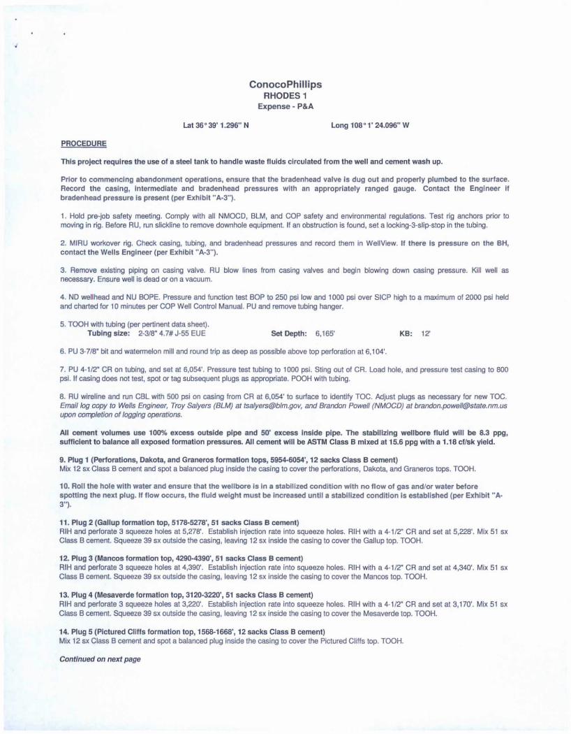
ConocoPhillips RHODES 1
Expense - P&A
Lat 36° 39' 1.296" N
PROCEDURE
Long 108° 1’ 24.096" W
This project requires the use of a steel tank to handle waste fluids circulated from the well and cement wash up.
Prior to commencing abandonment operations, ensure that the bradenhead valve is dug out and properly plumbed to the surface. Record the casing, intermediate and bradenhead pressures with an appropriately ranged gauge. Contact the Engineer if bradenhead pressure is present (per Exhibit "A-3").
1. Hold pre-job safety meeting. Comply with all NMOCD, BLM, and COP safety and environmental regulations. Test rig anchors prior to moving in rig. Before RU, run slickline to remove downhole equipment. If an obstruction is found, set a locking-3-slip-stop in the tubing.
2. MIRU workover rig. Check casing, tubing, and bradenhead pressures and record them in WellView. If there is pressure on the BH, contact the Wells Engineer (per Exhibit "A-3").
3. Remove existing piping on casing valve. RU blow lines from casing valves and begin blowing down casing pressure. Kill well as necessary. Ensure well is dead or on a vacuum.
4. ND wellhead and NU BOPE. Pressure and function test BOP to 250 psi low and 1000 psi over SICP high to a maximum of 2000 psi held and charted for 10 minutes per COP Well Control Manual. PU and remove tubing hanger.
5. TOOH with tubing (per pertinent data sheet).Tubing size: 2-3/8" 4.7# J-55 EUE Set Depth: 6,165' KB: 12'
6. PU 3-7/8" bit and watermelon mill and round trip as deep as possible above top perforation at 6,104'.
7. PU 4-1/2" CR on tubing, and set at 6,054'. Pressure test tubing to 1000 psi. Sting out of CR. Load hole, and pressure test casing to 800 psi. If casing does not test, spot or tag subsequent plugs as appropriate. POOH with tubing.
8. RU wireline and run CBL with 500 psi on casing from CR at 6,054' to surface to identify TOC. Adjust plugs as necessary for new TOC. Email log copy to Wells Engineer, Troy Salyers (BLM) at [email protected], and Brandon Powell (NMOCD) at [email protected] upon completion of logging operations.
All cement volumes use 100% excess outside pipe and 50' excess inside pipe. The stabilizing wellbore fluid will be 8.3 ppg, sufficient to balance all exposed formation pressures. All cement will be ASTM Class B mixed at 15.6 ppg with a 1.18 cf/sk yield.
9. Plug 1 (Perforations, Dakota, and Graneros formation tops, 5954-6054', 12 sacks Class B cement)Mix 12 sx Class B cement and spot a balanced plug inside the casing to cover the perforations, Dakota, and Graneros tops. TOOH.
10. Roll the hole with water and ensure that the wellbore is in a stabilized condition with no flow of gas and/or water before spotting the next plug. If flow occurs, the fluid weight must be increased until a stabilized condition is established (per Exhibit "A- 3").
11. Plug 2 (Gallup formation top, 5178-5278', 51 sacks Class B cement)RIH and perforate 3 squeeze holes at 5,278'. Establish injection rate into squeeze holes. RIH with a 4-1/2" CR and set at 5,228'. Mix 51 sx Class B cement. Squeeze 39 sx outside the casing, leaving 12 sx inside the casing to cover the Gallup top. TOOH.
12. Plug 3 (Mancos formation top, 4290-4390', 51 sacks Class B cement)RIH and perforate 3 squeeze holes at 4,390'. Establish injection rate into squeeze holes. RIH with a 4-1/2” CR and set at 4,340'. Mix 51 sx Class B cement. Squeeze 39 sx outside the casing, leaving 12 sx inside the casing to cover the Mancos top. TOOH.
13. Plug 4 (Mesaverde formation top, 3120-3220', 51 sacks Class B cement)RIH and perforate 3 squeeze holes at 3,220'. Establish injection rate into squeeze holes. RIH with a 4-1/2" CR and set at 3,170'. Mix 51 sx Class B cement. Squeeze 39 sx outside the casing, leaving 12 sx inside the casing to cover the Mesaverde top. TOOH.
14. Plug 5 (Pictured Cliffs formation top, 1568-1668’, 12 sacks Class B cement)Mix 12 sx Class B cement and spot a balanced plug inside the casing to cover the Pictured Cliffs top. TOOH.
Continued on next page
ConocoPhillips RHODES 1
Expense - P&A
Lat 36° 39’ 1.296" N Long 108° 1' 24.096" W
PROCEDURE (continued)
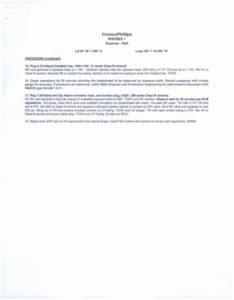
15. Plug 6 (Fruitland formation top, 1090-1190', 51 sacks Class B cement)RIH and perforate 3 squeeze holes at 1,190'. Establish injection rate into squeeze holes. RIH with a 4-1/2" CR and set at 1,140'. Mix 51 sx Class B cement. Squeeze 39 sx outside the casing, leaving 12 sx inside the casing to cover the Fruitland top. TOOH.
16. Cease operations for 30 minutes allowing the bradenhead to be observed for pressure build. Record pressures with crystal gauge for accuracy. If pressures are observed, notify Wells Engineer and Production Engineering for path-forward discussion with NMOCD (per Exhibit "A-3").
17. Plug 7 (Kirtland and Ojo Alamo formation tops, and surface plug, 0-625', 268 sacks Class B cement)RU WL and perforate 4 big hole charge (if available) squeeze holes at 625'. TOOH and RD wireline. Observe well for 30 minutes per BLM regulations. RU pump, close blind rams and establish circulation out bradenhead with water. Circulate BH clean. TIH with 4-1/2” CR and set at 575'. Mix 220 sx Class B cement and squeeze until good cement returns to surface out BH valve. Shut BH valve and squeeze to max 200 psi. Sting out of CR and reverse circulate cement out of tubing. TOOH and LD stinger. TIH with open ended tubing to 575'. Mix 48 sx Class B cement and pump inside plug. TOOH and LD Tubing. SI well and WOC.
18. Nipple down BOP and cut off casing below the casing flange. Install P&A marker with cement to comply with regulations. RDMO.

Ex hi Ml “A -3"
To Final Agreement- Withdrawal of Notice of Violation (3-15-02)
dated May 4 2016 from Conoco Phillips Company fc> NMOCD
Updated Abandonment Procedures
The following procedural changes will be required for the P&A Program:
1) Prior lo commencing abandonment operations, ensure that the bradenhead valve is
dug out and properly plumbed to the surface. Record the casing, intermediate and
bradenhead pressures with an appropriately ranged gauge. Contact the Engineer if
bradenhead pressure is present. After the last set of completion perforations are
abandoned with cement roll the hole with water and ensure that the wellbore is in a
stabilized condition with no flow of gas and/or water before spotting the next plug.
If flow occurs, the fluid weight must be increased until a stabilized condition is
established.
2) Following the plug over the Fruiitand Formation Top. and prior to the plug over the
Kirtland and Qjo Alamo Tops:
a. Operations will cease far 30 minutes allowing the Bradenhead to be observed for pressure build.
b. Pressures will be recorded with a crystal gauge for accuracy.
c. If pressures as observed, notify Wells Engineer and Production Engineering
far {nth-forward discussion with NMOCD.
3) Within 24 hours of the abandonment and after two weeks. BLM will check for the
presence of gas at the base of the dry hole marker and at the weep hole. Note ambient
weather conditions when recording the results. If gas is delected, contact the
Engineer.
4) If a Cathodic Protection well is on the well pad. check far the presence of gas at the
vent cap If gas is present record results in AFMSS and contact the Engineer.
Note: when checking any sample point for the presence of gas. please be prepared for the
possibility of anomalous pressure and the H2S gas.

GREENHORN
DAKOTA
IPInned Collar; 2 3/8 In; 6,194.0 ftKB;
mo "KB
I PBTD; 6,267.0lasing; Productionl; 4 1/2 In; 10.50
Ib/Tt J-SS: 12.0 ftKB 6 299.0 WKBProduction Casing Cement 5,496.0-
6,300.0; 11/27/1966; 1st Stage; Cmfd w/200 sx Class C cement,
TOC a 6495- by 76% eff calc.Auto cement plug; 6.267 .06,300.0; 11/27/1966; Automatically created
:ement plug from the casing cement because il had a lagged depth.
Schematic - Current
RHODES 1ConocoPhillips
Vertical - Original Hole, 12/2/1965
Vertical schematic (actual)_________ Formation Tops
12.1
Casing; Surface; B 6/8 in, 24.00 Ib/Tt J-66, 12.0 ftKB; 213.0flKB2119
Surface Casing Cement; 12 0-213.0; 11/18/1965. Cmfd w/136 sx Class A
_______ cement, circ cmt to surface.212.9
388 1 OJO ALAMO
KIRTLAND
FRUfTLAND
5761
1,140.1
1.617.1 /SB|DV Tool Q 1712'
1,618.1 PICTURED CLIFFSProduction Casing Cement 1.617.0- 1,712.0; 11/27/1966; 2nd Stage;
Cmfd w/50 sx Class A cement 40% Dlacel, TOC Q 161T by 76% eff.
calc.
1,711 9
1,712.9
1,774.9 LEWIS
CUFF HOUSE
MENEFEE
POINT LOOKOUT
MANCOS
GALLUP
3,169.9
3.284.1
4,022.0
4,339 9
5.228 0
6 4961
6.005 9
6.065.9
6.104 0
6.132.9
6,164 0
I Pinned Collar 0616616.165.0
6,168 0
6,233 5
6 267.1
6.297.9
6,298.9
6.2599
Page 1/1 Report Printed: 3/9/2016

District
[Surface Casing Camera. ------------11.16 1365 C.eu13w.'136m Class A cemerc
OJO ALAMO
WRTLAND
FRUIT LAND
Production Casing Censer*: 1.517.0-1.712.0 11/2?/19e6; * — “_ Cm"3»'5D5j( Clsss
' A camera «% DM. TCC 8 WIT by 75S eff. cefc.
MENEFEE
POINT LOOKOUT
MANCOS
GALLUP
ClAKOTA:
etnaidihftS«M 303 0
ConocoPhillipsSchematic - Proposed
RHODES 1
OTTginal Sp^Jd Date----------------- Surface Legal Locator EastTWest Distance [ft* EastWest Reference Norm'South Distance (ft) North; South Reference11/16/1965 020-028N-C11W-G 1.700. CO FEL 1.650.00 FNL
Vertical - Original Hole, 1/1/2020
12,1
212.9
575.1
625.0
1.140.1
1.190.0
1.5675
1.668.0
1.7125
3.120.1
3.171.9
3.284.1
4.290.0
4,3415
6.178.1
6.230.0
6.496.1
6.005.9
6.066.1
6.104.0
6.165.0
6.233.9
6.297.9
6.299.9
Vertical schematic (actual)
----------------------------- ------------------------------------gg
Casing; Surface; 8 5/8 in; 24.CO ItuTt •?&&! J-66: 12.011KB: 213.0 flKB
Idvtooi e i7izl-------------
iPinncd Collar 061651-
iasing; Productionl; 4 1/2 in; 10.50 Ibfft J-S5; 12.011KB: 6299.0 ft KB
Formation Tops
LEWIS
CUFF HOUSE
GRANEROS
DAKOTA
Page 1/1 Report Printed: 5/9/2016

UNITED STATES DEPARTMENT OF THE INTERIOR BUREAU OF LAND MANAGEMENT FARMINGTON DISTRICT OFFICE
6251 COLLEGE BLVD. FARMINGTON, NEW MEXICO 87402
Attachment to notice of Intention to Abandon:
Re: Permanent Abandonment Well: Rhodes 1
CONDITIONS OF APPROVAL1. Plugging operations authorized are subject to the attached "General Requirements for Permanent Abandonment of Wells on Federal and Indian Lease."
2. Farmington Office is to be notified at least 24 hours before the plugging operations commence (505) 564-7750.
3. The following modifications to your plugging program are to be made:
a) Set plug #4 (3093-3193) ft. inside/outside to cover Mesa Verde Formation top. BLM picks top of Mesa Verde at 3143 ft.
b) Set plug #6 (1285-1385) ft. inside/outside to cover Fruitland Formation top. BLM picks top of Fruitland at 1335 ft.
You are also required to place cement excesses per 4.2 and 4.4 of the attached General Requirements.
Office Hours: 7:45 a.m. to 4:30 p.m.


![SICP [SV-Series] User Manual - GPO Display](https://img.pdfslide.us/doc/110x75/6258237aefeefe074308e80b/sicp-sv-series-user-manual-gpo-display.jpg)