Embed Size (px)
Citation preview
maxon motor maxon motor control EPOS Positioning Controller Getting Started Edition July 2007
maxon document number 573049-08
24/1
Positioning Controller
Documentation
Getting Started
maxon motor EPOS Positioning Controller EPOS 24/1 Getting Started
1 Table of contents 1 Table of contents ...................................................................................................................2 2 Table of figures ......................................................................................................................3 3 Introduction ............................................................................................................................4 4 How to use this guide ............................................................................................................4 5 Safety Instructions .................................................................................................................5 6 Installation and Configuration ................................................................................................6
6.1 Step 1: Software Installation................................................................................................6 6.2 Step 2: Minimum External Wiring ........................................................................................7
6.2.1 EPOS 24/1 for maxon DC motor with integrated motor/encoder ribbon cable ...............7 6.2.2 EPOS 24/1 for maxon EC 6 motor with Hall sensor and digital MR-Encoder.................9 6.2.3 EPOS 24/1 for maxon EC16/EC22 motor with Hall sensor and digital Encoder...........11 6.2.4 EPOS 24/1 for maxon DC/EC motor (Molex connectors) with Hall sensor and digital
Encoder .........................................................................................................................13 6.3 Step 3: System Configuration............................................................................................15 6.4 Step 4: Regulation Gains Tuning.......................................................................................22
6.4.1 Start the Auto-tuning Tool..............................................................................................22 6.4.2 Auto-tuning of the Current Regulator.............................................................................23 6.4.3 Auto-tuning of the Velocity Regulator ............................................................................25 6.4.4 Auto-tuning of the Position Regulator............................................................................27 6.4.5 Manual Tuning...............................................................................................................29 6.4.6 Save all Regulation Gains .............................................................................................30
7 Conclusion ...........................................................................................................................30
2 maxon motor control Edition July 2007 / Subject to change
maxon motor EPOS 24/1 Getting Started EPOS Positioning Controller
2 Table of figures Figure 1: EPOS 24/1 photo ..............................................................................................................4 Figure 2: EPOS documentation hierarchy........................................................................................4 Figure 3: EPOS CD-ROM ................................................................................................................6 Figure 4: Minimum wiring for DC-Motor with integrated motor/encoder ribbon cable......................8 Figure 5: Minimum wiring for EC 6-Motor ......................................................................................10 Figure 6: Minimum wiring for EC16/EC22-Motor ...........................................................................12 Figure 7: Minimum wiring for DC/EC-Motor with Molex connectors ..............................................14 Figure 8: Startup wizard dialog for minimum external wiring .........................................................15 Figure 9: Startup wizard dialog for setting RS-232 communication...............................................16 Figure 10: Communication settings found......................................................................................16 Figure 11: Startup wizard dialog for choosing motor type..............................................................16 Figure 12: Startup wizard dialog for choosing EC motor pole pairs...............................................17 Figure 13: Startup wizard dialog for setting DC motor data ...........................................................17 Figure 14: Startup wizard dialog for setting EC motor data ...........................................................17 Figure 15: Startup wizard dialog for choosing DC motor position sensor type ..............................17 Figure 16: Startup wizard dialog for choosing EC motor position sensor type ..............................18 Figure 17: Recommendations for using Hall sensors as position sensors ....................................18 Figure 18: Startup wizard dialog for setting DC motor encoder resolution ....................................18 Figure 19: Startup wizard dialog for setting EC motor encoder resolution ....................................19 Figure 20: Startup wizard configuration summary .........................................................................19 Figure 21: Startup wizard dialog for setting EC motor encoder resolution ....................................20 Figure 22: Save & activate the configured parameters..................................................................20 Figure 23: Confirm parameter activation........................................................................................20 Figure 24: Clear CAN error ............................................................................................................21 Figure 25: Start regulation tuning...................................................................................................22 Figure 26: Auto-tuning of current regulator ....................................................................................23 Figure 27: Auto-tuning button.........................................................................................................23 Figure 28: Confirm motor shaft blocking ........................................................................................23 Figure 29: Confirm end of tuning....................................................................................................24 Figure 30: Confirm tuning error ......................................................................................................24 Figure 31: Clear tuning error ..........................................................................................................24 Figure 32: Auto-tuning of velocity regulator ...................................................................................25 Figure 33: Auto-tuning button.........................................................................................................25 Figure 34: Confirm free running of motor .......................................................................................25 Figure 35: Confirm end of tuning....................................................................................................26 Figure 36: Confirm tuning error ......................................................................................................26 Figure 37: Clear tuning error ..........................................................................................................26 Figure 38: Auto-tuning of position regulator ...................................................................................27 Figure 39: Auto-tuning button.........................................................................................................27 Figure 40: Confirm free running of motor .......................................................................................27 Figure 41: Confirm end of tuning....................................................................................................28 Figure 42: Confirm tuning error ......................................................................................................28 Figure 43: Clear tuning error ..........................................................................................................28 Figure 44: Manual tuning mode .....................................................................................................29 Figure 45: Manual tuning mode .....................................................................................................29 Figure 46: Next tuning step ............................................................................................................29 Figure 47: Save button ...................................................................................................................30 Figure 48: Confirm regulation gains saving....................................................................................30 Figure 49: Confirm saving of all parameters ..................................................................................30
Edition July 2007 / Subject to change maxon motor control 3
maxon motor EPOS Positioning Controller EPOS 24/1 Getting Started
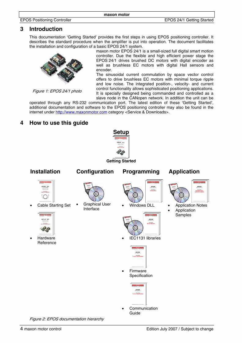
3 Introduction This documentation ‘Getting Started’ provides the first steps in using EPOS positioning controller. It describes the standard procedure when the amplifier is put into operation. The document facilitates the installation and configuration of a basic EPOS 24/1 system.
maxon motor EPOS 24/1 is a small-sized full digital smart motion controller. Due the flexible and high efficient power stage the EPOS 24/1 drives brushed DC motors with digital encoder as well as brushless EC motors with digital Hall sensors and encoder. The sinusoidal current commutation by space vector control offers to drive brushless EC motors with minimal torque ripple and low noise. The integrated position-, velocity- and current control functionality allows sophisticated positioning applications. It is specially designed being commanded and controlled as a slave node in the CANopen network. In addition the unit can be
operated through any RS-232 communication port. The latest edition of these ‘Getting Started’, additional documentation and software to the EPOS positioning controller may also be found in the internet under http://www.maxonmotor.com category <Service & Downloads>.
Figure 1: EPOS 24/1 photo
4 How to use this guide
Setup
Getting Started
Installation Configuration Programming Application
• Cable Starting Set
• Hardware
Reference
• Graphical User
Interface
• Windows DLL
• IEC1131 libraries
• Firmware
Specification
• Communication
Guide
• Application Notes • Application
Samples
Figure 2: EPOS documentation hie archy r
4 maxon motor control Edition July 2007 / Subject to change
maxon motor EPOS 24/1 Getting Started EPOS Positioning Controller
5 Safety Instructions
Skilled Personnel Installation and starting of the equipment shall only be performed by experienced, skilled personnel.
Statutory Regulations The user must ensure that the positioning controller and the components belonging to it are assembled and connected according to local statutory regulations.
Load Disconnected For primary operation the motor should be free running, i.e. with the load disconnected.
Additional Safety Equipment An electronic apparatus is not fail-safe in principle. Machines and apparatus must therefore be fitted with independent monitoring and safety equipment. If the equipment breaks down, if it is operated incorrectly, if the control unit breaks down or if the cables break, etc., it must be ensured that the drive or the complete apparatus is kept in a safe operating mode.
Repairs Repairs may be made by authorized personnel only or by the manufacturer. It is dangerous for the user to open the unit or make repairs to it.
Danger Do ensure that during the installation of the EPOS 24/1 no apparatus is connected to the electrical supply. After switching on, do not touch any live parts!
Max. Supply Voltage Make sure that the supply voltage is between 9 and 24 VDC. Voltages higher than 27 VDC or of wrong polarity will destroy the unit.
Electrostatic Sensitive Device (ESD)
Edition July 2007 / Subject to change maxon motor control 5
maxon motor EPOS Positioning Controller EPOS 24/1 Getting Started
6 Installation and Configuration
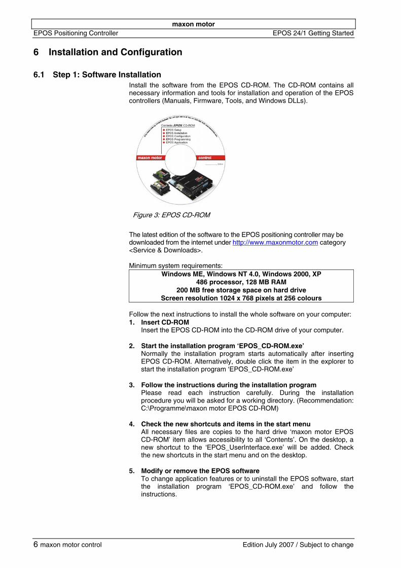
6.1 Step 1: Software Installation Install the software from the EPOS CD-ROM. The CD-ROM contains all necessary information and tools for installation and operation of the EPOS controllers (Manuals, Firmware, Tools, and Windows DLLs).
Figure 3: EPOS CD-ROM
The latest edition of the software to the EPOS positioning controller may be downloaded from the internet under http://www.maxonmotor.com category <Service & Downloads>. Minimum system requirements:
Windows ME, Windows NT 4.0, Windows 2000, XP 486 processor, 128 MB RAM
200 MB free storage space on hard drive Screen resolution 1024 x 768 pixels at 256 colours
Follow the next instructions to install the whole software on your computer: 1. Insert CD-ROM
Insert the EPOS CD-ROM into the CD-ROM drive of your computer.
2. Start the installation program ‘EPOS_CD-ROM.exe’ Normally the installation program starts automatically after inserting EPOS CD-ROM. Alternatively, double click the item in the explorer to start the installation program ‘EPOS_CD-ROM.exe’
3. Follow the instructions during the installation program Please read each instruction carefully. During the installation procedure you will be asked for a working directory. (Recommendation: C:\Programme\maxon motor EPOS CD-ROM)
4. Check the new shortcuts and items in the start menu All necessary files are copies to the hard drive ‘maxon motor EPOS CD-ROM’ item allows accessibility to all ‘Contents’. On the desktop, a new shortcut to the ‘EPOS_UserInterface.exe’ will be added. Check the new shortcuts in the start menu and on the desktop.
5. Modify or remove the EPOS software To change application features or to uninstall the EPOS software, start the installation program ‘EPOS_CD-ROM.exe’ and follow the instructions.
6 maxon motor control Edition July 2007 / Subject to change
maxon motor EPOS 24/1 Getting Started EPOS Positioning Controller
Edition July 2007 / Subject to change maxon motor control 7
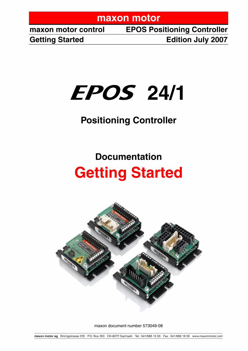
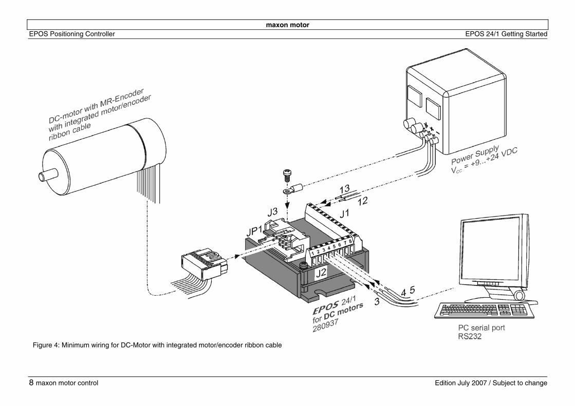
6.2.1 EPOS 24/1 for maxon DC motor with integrated motor/encoder ribbon cable Next option allows hardware installation of EPOS 24/1 for maxon DC motor with integrated motor/encoder ribbon cable (Order No. 280937). Follow the steps and see also figure 4.
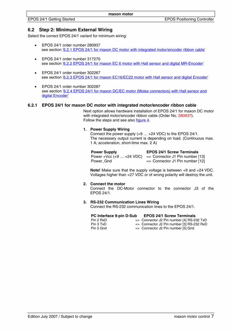
Select the correct EPOS 24/1 variant for minimum wiring:
• EPOS 24/1 order number 280937 see section '6.2.1 EPOS 24/1 for maxon DC motor with integrated motor/encoder ribbon cable'
6.2 Step 2: Minimum External Wiring
• EPOS 24/1 order number 302267 see section '6.2.3 EPOS 24/1 for maxon EC16/EC22 motor with Hall sensor and digital Encoder'
• EPOS 24/1 order number 317270 see section '6.2.2 EPOS 24/1 for maxon EC 6 motor with Hall sensor and digital MR-Encoder'
• EPOS 24/1 order number 302287 see section '6.2.4 EPOS 24/1 for maxon DC/EC motor (Molex connectors) with Hall sensor and digital Encoder’
1. Power Supply Wiring Connect the power supply (+9 … +24 VDC) to the EPOS 24/1. The necessary output current is depending on load. (Continuous max. 1 A; acceleration, short-time max. 2 A) Power Supply EPOS 24/1 Screw Terminals Power +Vcc (+9 … +24 VDC) => Connector J1 Pin number [13] Power_Gnd => Connector J1 Pin number [12] Note! Make sure that the supply voltage is between +9 and +24 VDC. Voltages higher than +27 VDC or of wrong polarity will destroy the unit.
2. Connect the motor Connect the DC-Motor connector to the connector J3 of the EPOS 24/1.
3. RS-232 Communication Lines Wiring Connect the RS-232 communication lines to the EPOS 24/1. PC Interface 9-pin D-Sub EPOS 24/1 Screw Terminals Pin 2 RxD => Connector J2 Pin number [4] RS-232 TxD Pin 3 TxD => Connector J2 Pin number [3] RS-232 RxD Pin 5 Gnd => Connector J2 Pin number [5] Gnd
maxon motor
ge
EPOS Positioning Controll
8
er EPOS 24/1 Getting Started
maxon motor control Edition July 2007 / Subject to chan
Figure 4: Minimum wiring for DC-Motor with integrated motor/encoder ribbon cable
maxon motor EPOS 24/1 Getting Started EPOS Positioning Controller
Edition July 2007 / Subject to change maxon motor control 9
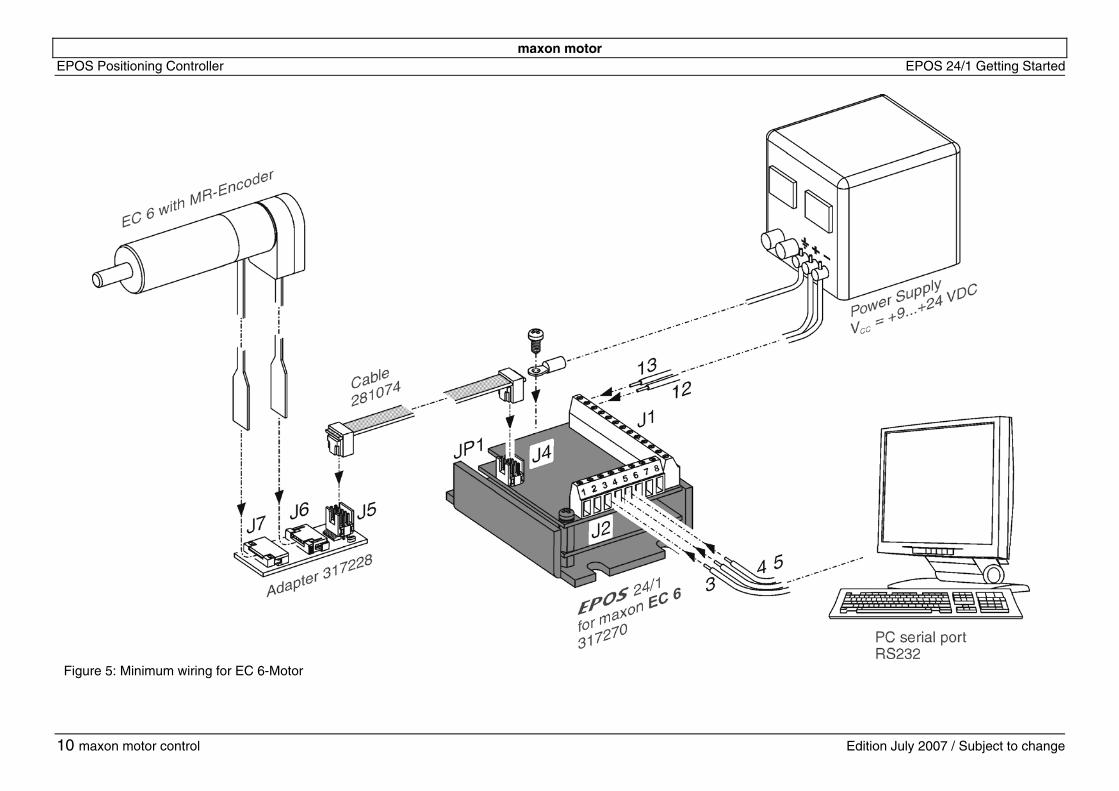
6.2.2 EPOS 24/1 for maxon EC 6 motor with Hall sensor and digital MR-Encoder Install the EPOS 24/1 hardware. Use the maxon cable assemblies below for wiring. You should have: EPOS 24/1 positioning controller for maxon EC 6 motor .................................................. order number 317270 EPOS cable (included in delivery of 317270) ......... order number 281074 EPOS adapter (included in delivery of 317270) ...... order number 317228 Follow the steps and see also figure 5. 1. Power supply wiring
Connect the power supply (+9 … +24 VDC) to the EPOS 24/1. The necessary output current is depending on load. (Continuous max. 1 A; acceleration, short-time max. 2 A) Power Supply EPOS 24/1 Screw Terminals Power +Vcc (+9 … +24 VDC) => Connector J1 Pin number [13] Power_Gnd => Connector J1 Pin number [12] Note! Make sure that the supply voltage is between +9 and +24 VDC. Voltages higher than +27 VDC or of wrong polarity will destroy the unit.
2. Connect maxon motor control Cable Connect cable (Order No. 281074) to the connector J4 of the EPOS 24/1 (Order No. 317270). On the opposite side connect to the connector J5 of the adapter (Order No. 317228).
3. Connect the maxon EC 6 motor Connect the EC 6 motor flex-print to the connector J7 of the adapter (Order No. 317228). Connect the EC 6 encoder flex-print to the connector J6 of the adapter (Order No. 317228).
4. RS-232 Communication Lines Wiring Connect the RS-232 communication lines to the EPOS 24/1. PC Interface 9-pin D-Sub EPOS 24/1 Screw Terminals Pin 2 RxD => Connector J2 Pin number [4] RS-232 TxD Pin 3 TxD => Connector J2 Pin number [3] RS-232 RxD Pin 5 Gnd => Connector J2 Pin number [5] Gnd
maxon motor
ge
EPOS Positioning Controll
10
er EPOS 24/1 Getting Started
maxon motor control Edition July 2007 / Subject to chan
Figure 5: Minimum wiring for EC 6-Motor
maxon motor EPOS 24/1 Getting Started EPOS Positioning Controller
Edition July 2007 / Subject to change maxon motor control 11
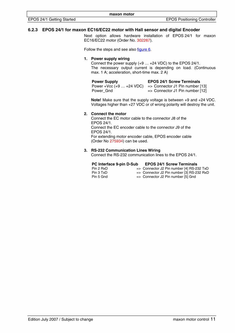
6.2.3 EPOS 24/1 for maxon EC16/EC22 motor with Hall sensor and digital Encoder Next option allows hardware installation of EPOS 24/1 for maxon EC16/EC22 motor (Order No. 302267). Follow the steps and see also figure 6. 1. Power supply wiring
Connect the power supply (+9 … +24 VDC) to the EPOS 24/1. The necessary output current is depending on load. (Continuous max. 1 A; acceleration, short-time max. 2 A) Power Supply EPOS 24/1 Screw Terminals Power +Vcc (+9 … +24 VDC) => Connector J1 Pin number [13] Power_Gnd => Connector J1 Pin number [12] Note! Make sure that the supply voltage is between +9 and +24 VDC. Voltages higher than +27 VDC or of wrong polarity will destroy the unit.
2. Connect the motor Connect the EC motor cable to the connector J8 of the EPOS 24/1. Connect the EC encoder cable to the connector J9 of the EPOS 24/1. For extending motor encoder cable, EPOS encoder cable (Order No 275934) can be used.
3. RS-232 Communication Lines Wiring Connect the RS-232 communication lines to the EPOS 24/1. PC Interface 9-pin D-Sub EPOS 24/1 Screw Terminals Pin 2 RxD => Connector J2 Pin number [4] RS-232 TxD Pin 3 TxD => Connector J2 Pin number [3] RS-232 RxD Pin 5 Gnd => Connector J2 Pin number [5] Gnd
maxon motor
ge
EPOS Positioning Controll
12
er EPOS 24/1 Getting Started
maxon motor control Edition July 2007 / Subject to chan
Figure 6: Minimum wiring for EC16/EC22-Motor
maxon motor EPOS 24/1 Getting Started EPOS Positioning Controller
Edition July 2007 / Subject to change maxon motor control 13
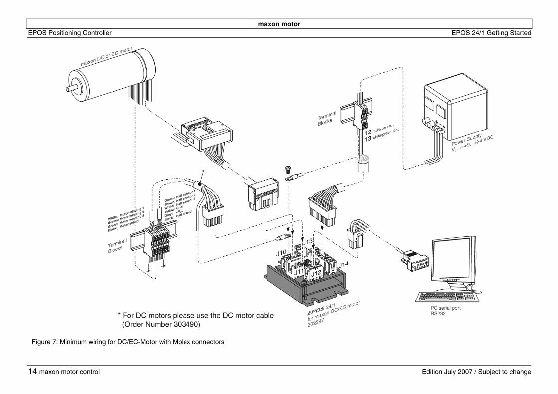
6.2.4 EPOS 24/1 for maxon DC/EC motor (Molex connectors) with Hall sensor and digital Encoder
Next option allows hardware installation of EPOS 24/1 for maxon DC/EC motor (Order No. 302287). Use the maxon cable assemblies below for wiring. You should have: EPOS 24/1 for maxon DC/EC motor .................... order number 302287 EPOS 24/1 EC motor / hall sensor cable (Connector J10)..................................................... order number 302948 or EPOS 24/1 DC motor cable (Connector J10) ...... order number 303490 EPOS encoder cable (Connector J11) ................. order number 275934 EPOS RS232-COM cable (Connector J12) ......... order number 275900 EPOS signal cable (Connector J14) .................... order number 275932
Follow the steps and see also figure 7. 1. Power supply wiring
Connect the signal cable (Order No. 275932) to the connector J14 of the EPOS 24/1. On the opposite side connect the red/blue (+Vcc) line and the white/green (Gnd) line to terminal blocks. Connect a power supply (+9 … +24 VDC) to the opposite side of the terminal blocks. The necessary output current is depending on load. (Continuous max. 1 A; acceleration, short-time max. 2 A) Note! Make sure that the supply voltage is between +9 and +24 VDC. Voltages higher than +27 VDC or of wrong polarity will destroy the unit.
2. Connect the motor a. EC motor Connect the EPOS 24/1 EC motor / hall sensor cable (Order No. 302948) to the connector J10 of the EPOS 24/1. On the opposite side connect to terminal blocks. Connect the motor Hall sensor and motor power lines to the opposite side of the terminal blocks. b. DC motor Connect the EPOS 24/1 DC motor cable (Order No. 303490) to the connector J10 of the EPOS 24/1. On the opposite side connect to terminal blocks. Connect the motor power lines to the opposite side of the terminal blocks.
3. Connect EPOS encoder cable Connect the encoder cable (Order No. 275934) to the connector J11 of the EPOS 24/1. On the opposite side connect to the encoder of the motor.
4. Connect EPOS RS232-COM cable Connect the RS232-COM cable (Order No. 275900) to the connector J12 of the EPOS 24/1. On the opposite side connect to a free RS-232 port of your computer.
Note! If you do not use the maxon cables, you have to do the wiring using the ‘EPOS 24/1 Cable Starting Set’ manual.
maxon motor
ge
EPOS Positioning Controll
14
er EPOS 24/1 Getting Started
maxon motor control Edition July 2007 / Subject to chan
Figure 7: Minimum wiring for DC/EC-Motor with Molex connectors
maxon motor EPOS 24/1 Getting Started EPOS Positioning Controller
6.3 Step 3: System Configuration In this section you will configure the EPOS 24/1 for your drive system. Please note:
• The EPOS User Interface provides an online help. It contains all available documentation. To open online help functions: - press F1
- or use the help buttons - or click the right mouse button
• You have to know some technical data about your system. Use the
maxon catalogue or the datasheets of the components used. To configure your drive system: 1. Power-up
Switch on the EPOS 24/1 power supply.
2. Start the ‘EPOS User Interface’ Version 2.00 or higher Double click on the item ‘EPOS UserInterface.exe’ on the desktop to start the graphical user interface (GUI). By starting the ‘EPOS User Interface’ the ‘Startup Wizard’ will be started automatically.
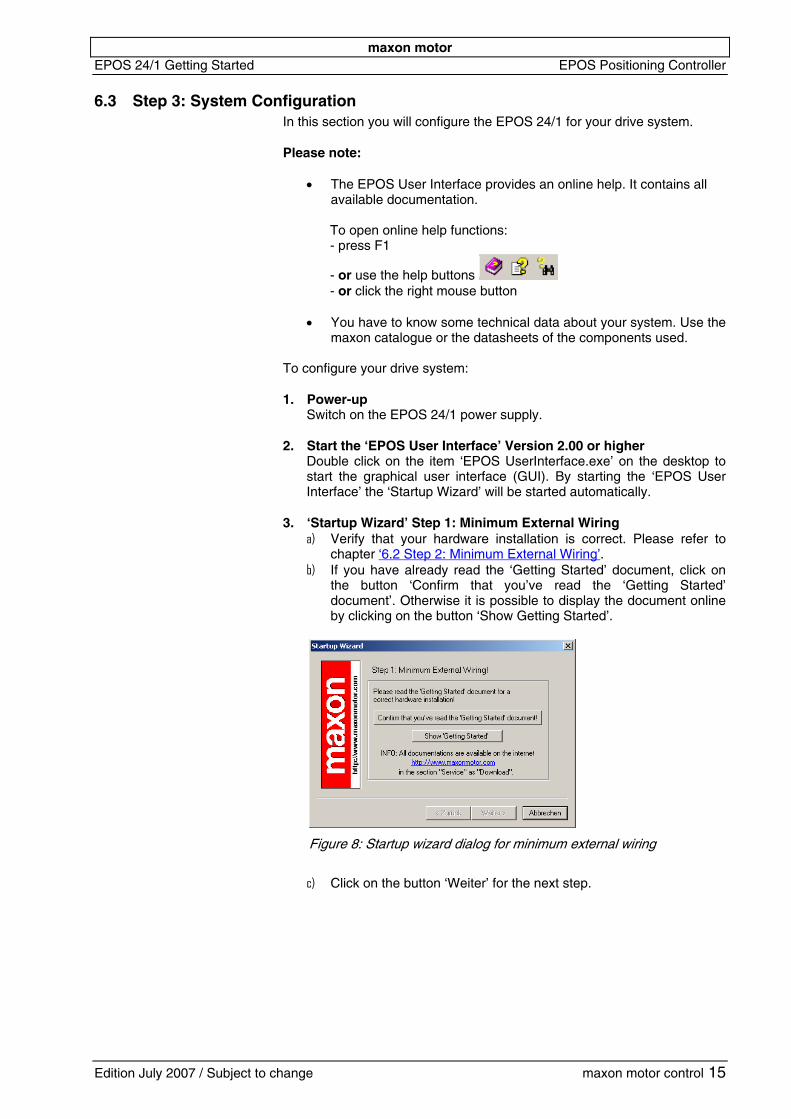
3. ‘Startup Wizard’ Step 1: Minimum External Wiring a) Verify that your hardware installation is correct. Please refer to
chapter ‘6.2 Step 2: Minimum External Wiring’. b) If you have already read the ‘Getting Started’ document, click on
the button ‘Confirm that you’ve read the ‘Getting Started’ document’. Otherwise it is possible to display the document online by clicking on the button ‘Show Getting Started’.
c)
Figure 8: Startup wizard dialog for minimum external wiring
Click on the button ‘Weiter’ for the next step.
Edition July 2007 / Subject to change maxon motor control 15
maxon motor EPOS Positioning Controller EPOS 24/1 Getting Started
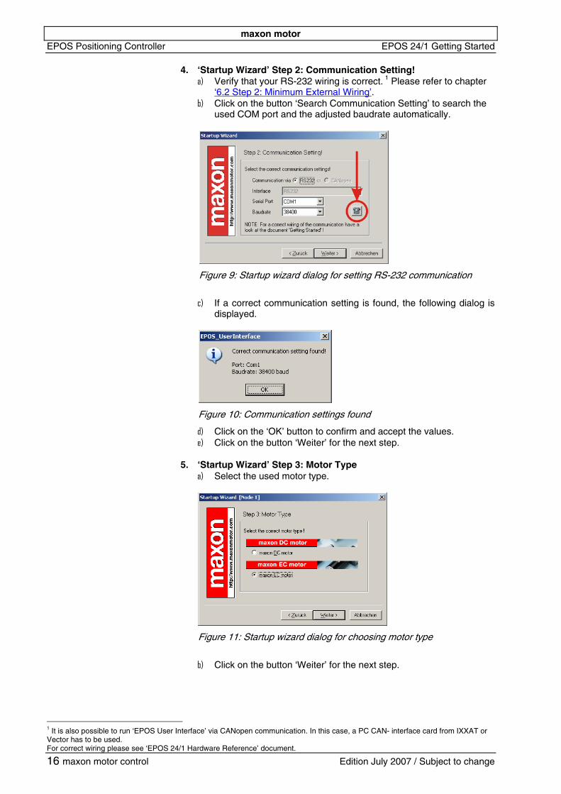
4. ‘Startup Wizard’ Step 2: Communication Setting!
Verify that your RS-232 wiring is correct. 1 Please refer to chapter ‘6.2 Step 2: Minimum External Wiring’.
a)
b) Click on the button ‘Search Communication Setting’ to search the used COM port and the adjusted baudrate automatically.
c)
Figure 9: Startup wizard dialog for setting RS-232 communication
If a correct communication setting is found, the following dialog is displayed.
d) e)
a)
Figure 10: Communication settings found
Click on the ‘OK’ button to confirm and accept the values. Click on the button ‘Weiter’ for the next step.
5. ‘Startup Wizard’ Step 3: Motor Type
Select the used motor type.
Figure 11: Startup wizard dialog for choosing motor type
b)
Click on the button ‘Weiter’ for the next step.
1 It is also possible to run ‘EPOS User Interface’ via CANopen communication. In this case, a PC CAN- interface card from IXXAT or Vector has to be used. For correct wiring please see ‘EPOS 24/1 Hardware Reference’ document.
16 maxon motor control Edition July 2007 / Subject to change
maxon motor EPOS 24/1 Getting Started EPOS Positioning Controller
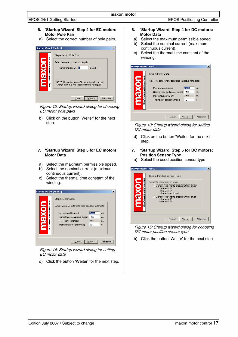
6. ‘Startup Wizard’ Step 4 for EC motors:
Motor Pole Pair a) Select the correct number of pole pairs.
Figure 12: Startup wizard dialog for choosingEC motor pole pairs
b)
a) b)
c)
Click on the button ‘Weiter’ for the next step.
6. ‘Startup Wizard’ Step 4 for DC motors: Motor Data Select the maximum permissible speed. Select the nominal current (maximum continuous current). Select the thermal time constant of the winding.
Figure 13: Startup wizard dialog for setting DC motor data
d) Click on the button ‘Weiter’ for the next step.
7. ‘Startup Wizard’ Step 5 for EC motors: Motor Data
a) b)
c)
Select the maximum permissible speed. Select the nominal current (maximum continuous current). Select the thermal time constant of the winding.
Figure 14: Startup wizard dialog for setting EC motor data
d)
a)
Click the button ‘Weiter’ for the next step.
7. ‘Startup Wizard’ Step 5 for DC motors: Position Sensor Type Select the used position sensor type
Figure 15: Startup wizard dialog for choosingDC motor position senso type
r
b) Click the button ‘Weiter’ for the next step.
Edition July 2007 / Subject to change maxon motor control 17
maxon motor EPOS Positioning Controller EPOS 24/1 Getting Started
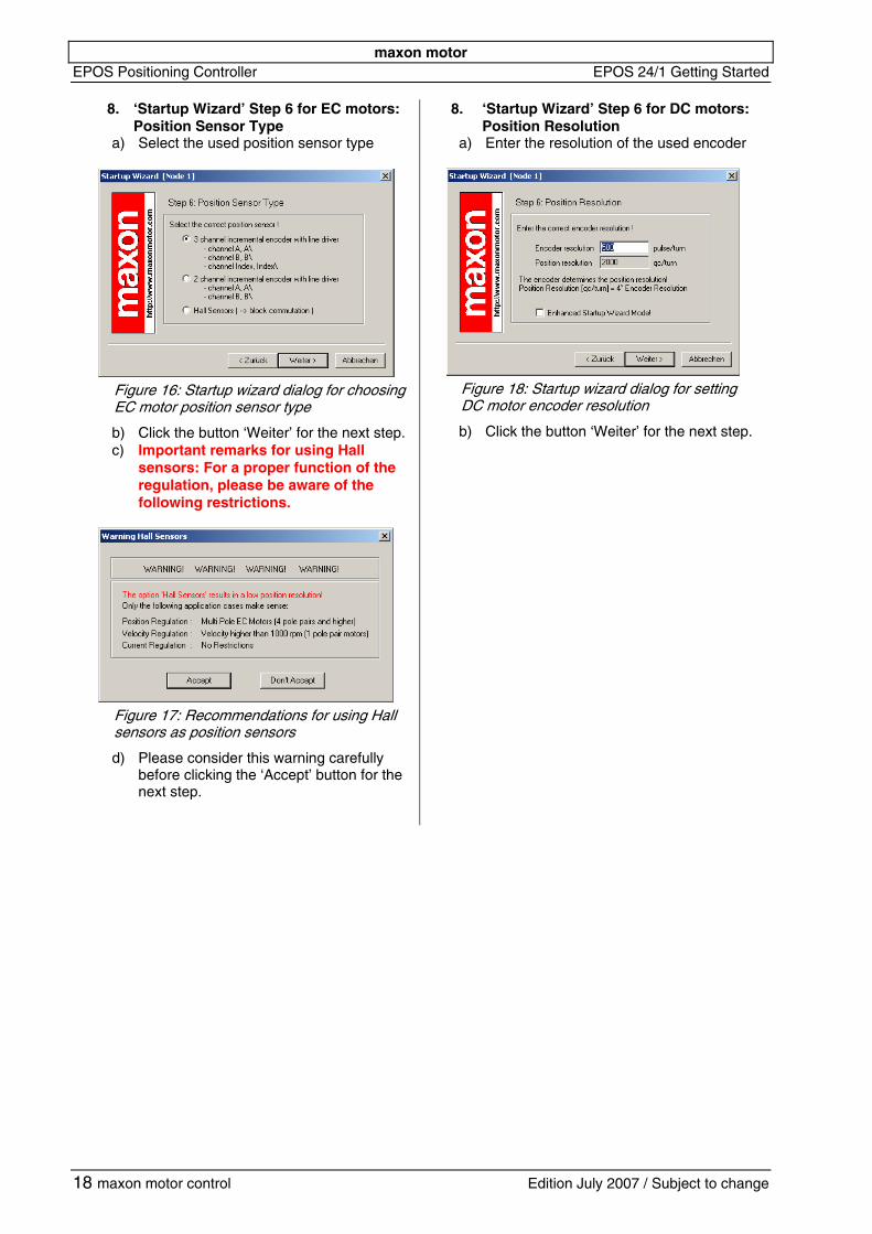
8. ‘Startup Wizard’ Step 6 for EC motors: Position Sensor Type
a) Select the used position sensor type
Figure 16: Startup wizard dialog for choosingEC motor position sensor type
b) c)
Click the button ‘Weiter’ for the next step. Important remarks for using Hall sensors: For a proper function of the regulation, please be aware of the following restrictions.
Figure 17: Recommendations for using Hall sensors as position sensors
d)
a)
Please consider this warning carefully before clicking the ‘Accept’ button for the next step.
8. ‘Startup Wizard’ Step 6 for DC motors: Position Resolution Enter the resolution of the used encoder
Figure 18: Startup wizard dialog for setting DC motor encoder resolution
b) Click the button ‘Weiter’ for the next step.
18 maxon motor control Edition July 2007 / Subject to change
maxon motor EPOS 24/1 Getting Started EPOS Positioning Controller
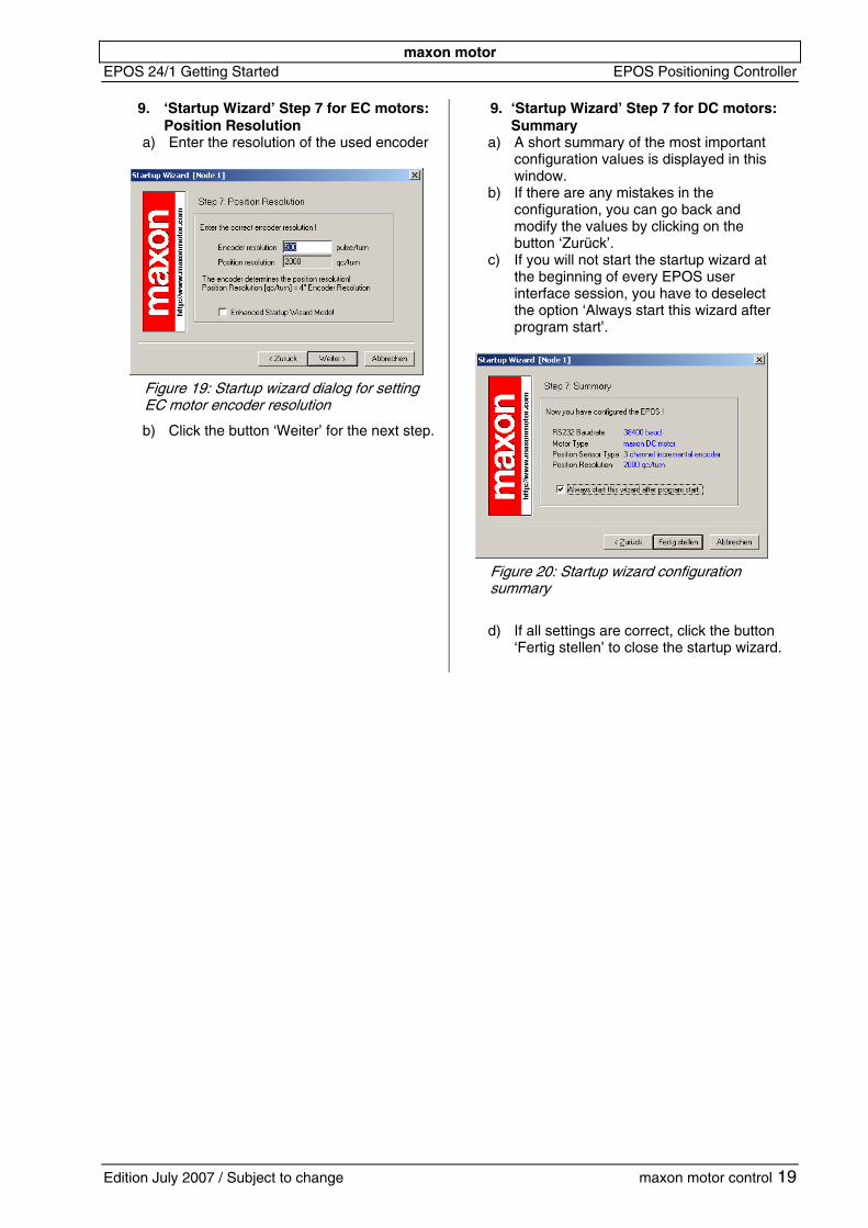
9. ‘Startup Wizard’ Step 7 for EC motors: Position Resolution
a) Enter the resolution of the used encoder
Figure 19: Startup wizard dialog for setting EC motor encoder resolution
b)
a)
b)
c)
Click the button ‘Weiter’ for the next step.
9. ‘Startup Wizard’ Step 7 for DC motors: Summary A short summary of the most important configuration values is displayed in this window. If there are any mistakes in the configuration, you can go back and modify the values by clicking on the button ‘Zurück’. If you will not start the startup wizard at the beginning of every EPOS user interface session, you have to deselect the option ‘Always start this wizard after program start’.
Figure 20: Startup wizard configuration summary
d) If all settings are correct, click the button
‘Fertig stellen’ to close the startup wizard.
Edition July 2007 / Subject to change maxon motor control 19
maxon motor EPOS Positioning Controller EPOS 24/1 Getting Started
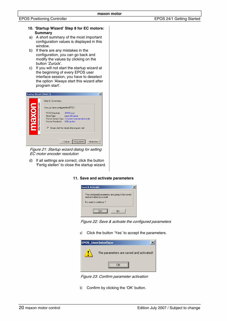
10. ‘Startup Wizard’ Step 8 for EC motors:
Summary a)
b)
c)
A short summary of the most important configuration values is displayed in this window. If there are any mistakes in the configuration, you can go back and modify the values by clicking on the button ‘Zurück’. If you will not start the startup wizard at the beginning of every EPOS user interface session, you have to deselect the option ‘Always start this wizard after program start’.
Figure 21: Startup wizard dialog for setting EC motor encoder resolution
d) If all settings are correct, click the button ‘Fertig stellen’ to close the startup wizard.
11. Save and activate parameters
r
a)
Figure 22: Save & activate the configured paramete s
Click the button ‘Yes’ to accept the parameters.
b)
Figure 23: Confirm parameter activation
Confirm by clicking the ‘OK’ button.
20 maxon motor control Edition July 2007 / Subject to change
maxon motor EPOS 24/1 Getting Started EPOS Positioning Controller
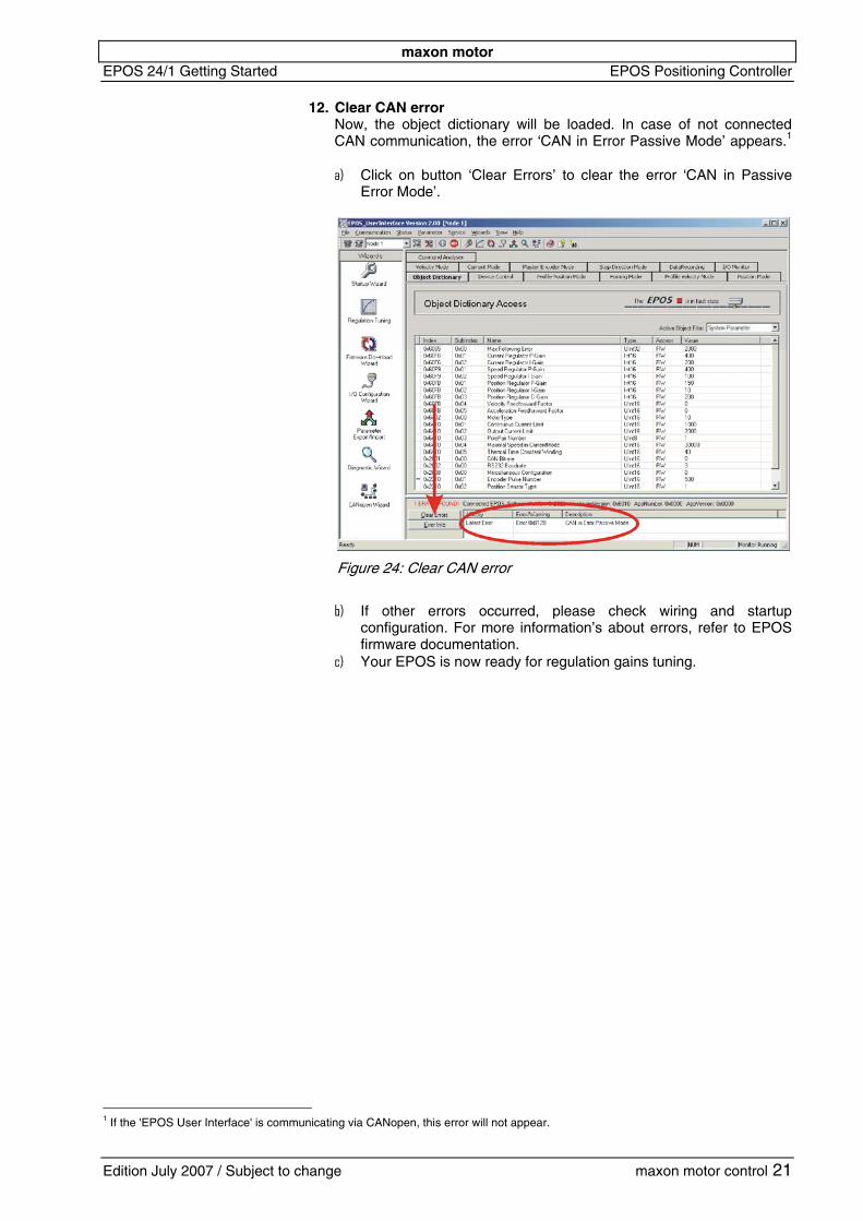
12. Clear CAN error
Now, the object dictionary will be loaded. In case of not connected CAN communication, the error ‘CAN in Error Passive Mode’ appears.1
a)
Click on button ‘Clear Errors’ to clear the error ‘CAN in Passive Error Mode’.
b)
c)
Figure 24: Clear CAN error
If other errors occurred, please check wiring and startup configuration. For more information’s about errors, refer to EPOS firmware documentation. Your EPOS is now ready for regulation gains tuning.
1 If the 'EPOS User Interface' is communicating via CANopen, this error will not appear.
Edition July 2007 / Subject to change maxon motor control 21
maxon motor EPOS Positioning Controller EPOS 24/1 Getting Started
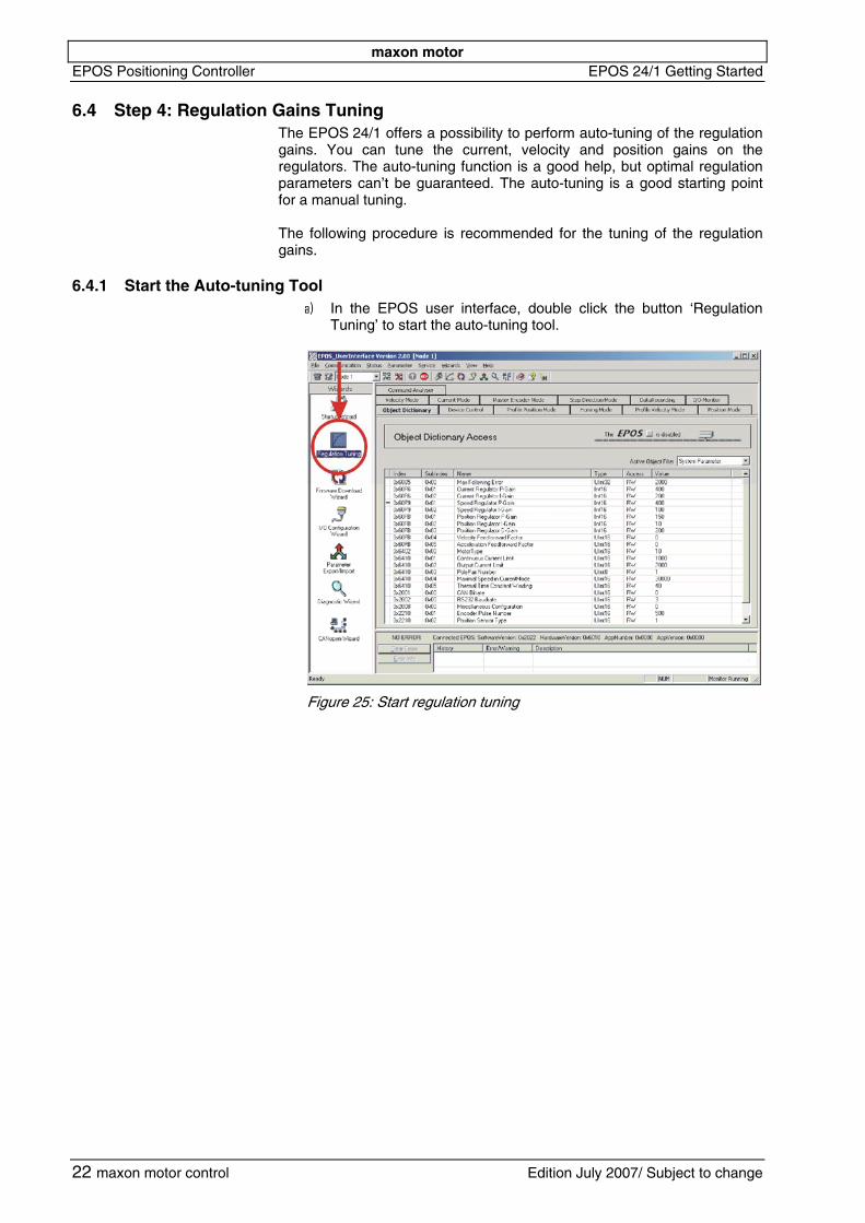
6.4 Step 4: Regulation Gains Tuning The EPOS 24/1 offers a possibility to perform auto-tuning of the regulation gains. You can tune the current, velocity and position gains on the regulators. The auto-tuning function is a good help, but optimal regulation parameters can’t be guaranteed. The auto-tuning is a good starting point for a manual tuning. The following procedure is recommended for the tuning of the regulation gains.
6.4.1 Start the Auto-tuning Tool a) In the EPOS user interface, double click the button ‘Regulation
Tuning’ to start the auto-tuning tool.
Figure 25: Start regulation tuning
22 maxon motor control Edition July 2007/ Subject to change
maxon motor EPOS 24/1 Getting Started EPOS Positioning Controller
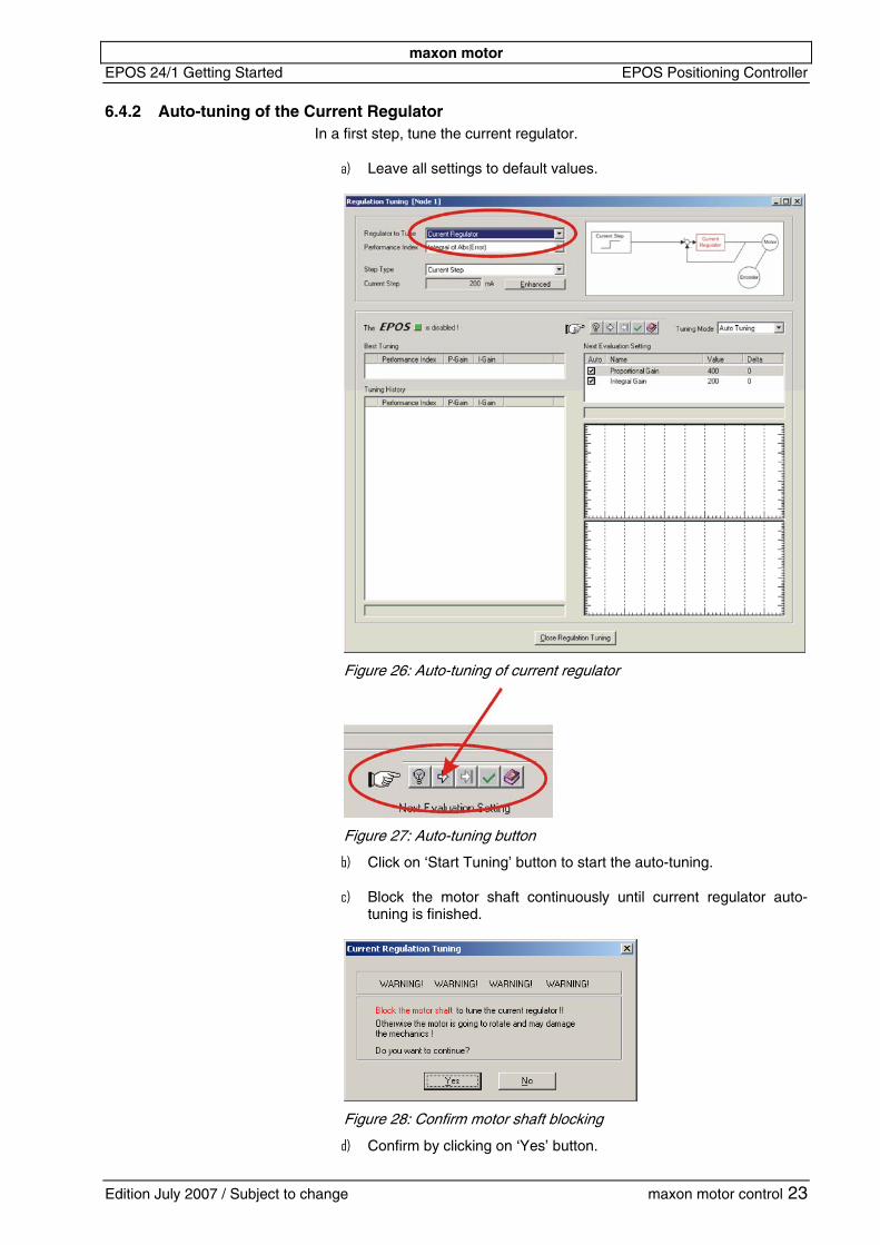
6.4.2 Auto-tuning of the Current Regulator In a first step, tune the current regulator.
a) Leave all settings to default values.
Figure 26: Auto-tuning of current regulator
b)
c)
Figure 27: Auto-tuning button
Click on ‘Start Tuning’ button to start the auto-tuning.
Block the motor shaft continuously until current regulator auto-tuning is finished.
d)
Figure 28: Confirm motor shaft blocking
Confirm by clicking on ‘Yes’ button.
Edition July 2007 / Subject to change maxon motor control 23
maxon motor EPOS Positioning Controller EPOS 24/1 Getting Started
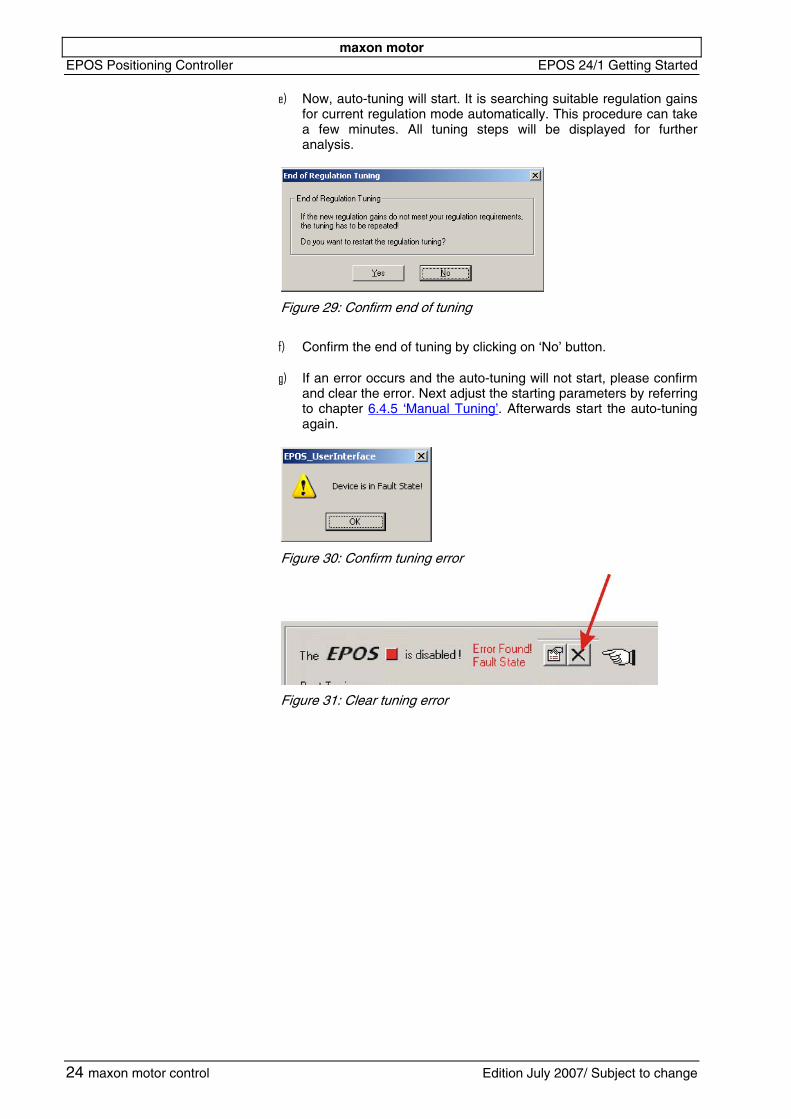
e) Now, auto-tuning will start. It is searching suitable regulation gains
for current regulation mode automatically. This procedure can take a few minutes. All tuning steps will be displayed for further analysis.
f)
g)
Figure 29: Confirm end of tuning
Confirm the end of tuning by clicking on ‘No’ button.
If an error occurs and the auto-tuning will not start, please confirm and clear the error. Next adjust the starting parameters by referring to chapter 6.4.5 ‘Manual Tuning’. Afterwards start the auto-tuning again.
Figure 30: Confirm tuning error
Figure 31: Clear tuning error
24 maxon motor control Edition July 2007/ Subject to change
maxon motor EPOS 24/1 Getting Started EPOS Positioning Controller
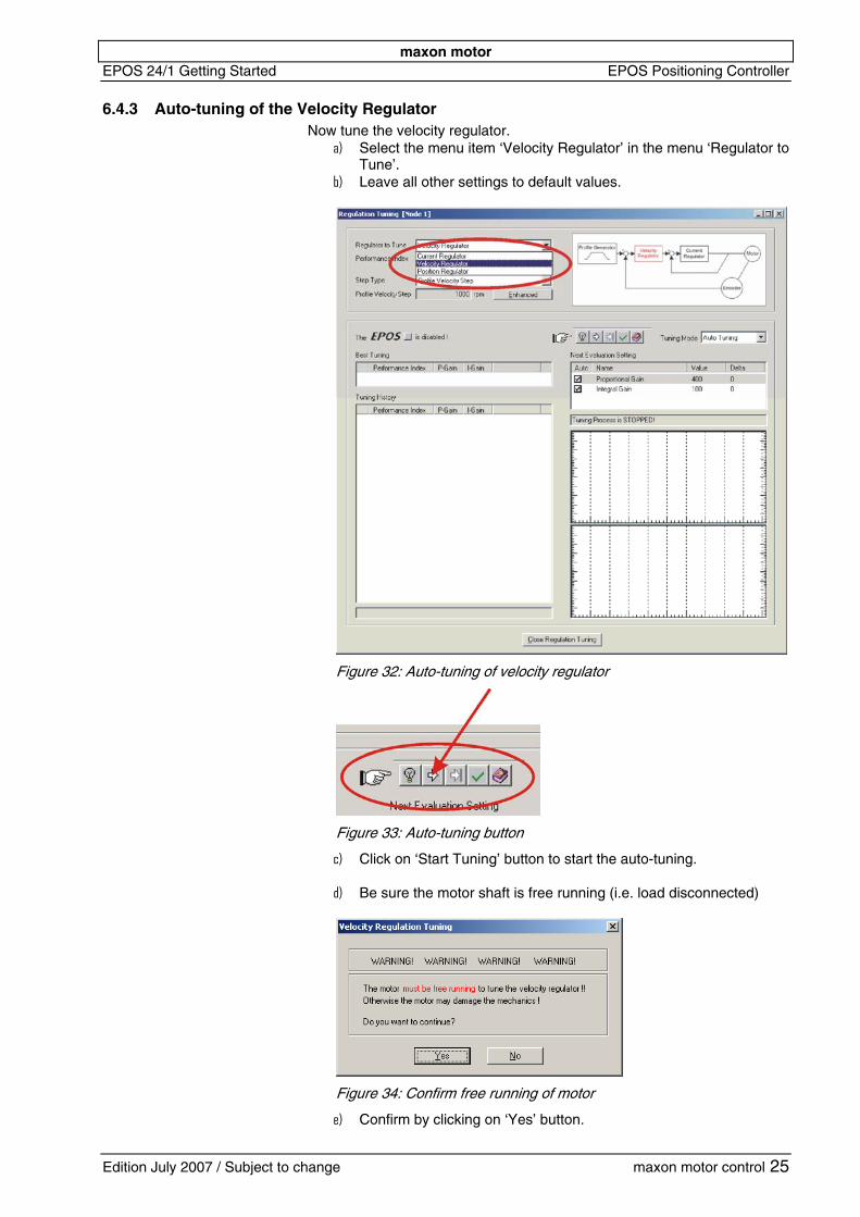
6.4.3 Auto-tuning of the Velocity Regulator Now tune the velocity regulator.
a)
b)
Select the menu item ‘Velocity Regulator’ in the menu ‘Regulator to Tune’. Leave all other settings to default values.
Figure 32: Auto-tuning of velocity regulator
c)
d)
Figure 33: Auto-tuning button
Click on ‘Start Tuning’ button to start the auto-tuning.
Be sure the motor shaft is free running (i.e. load disconnected)
e)
Figure 34: Confirm free running of motor
Confirm by clicking on ‘Yes’ button.
Edition July 2007 / Subject to change maxon motor control 25
maxon motor EPOS Positioning Controller EPOS 24/1 Getting Started
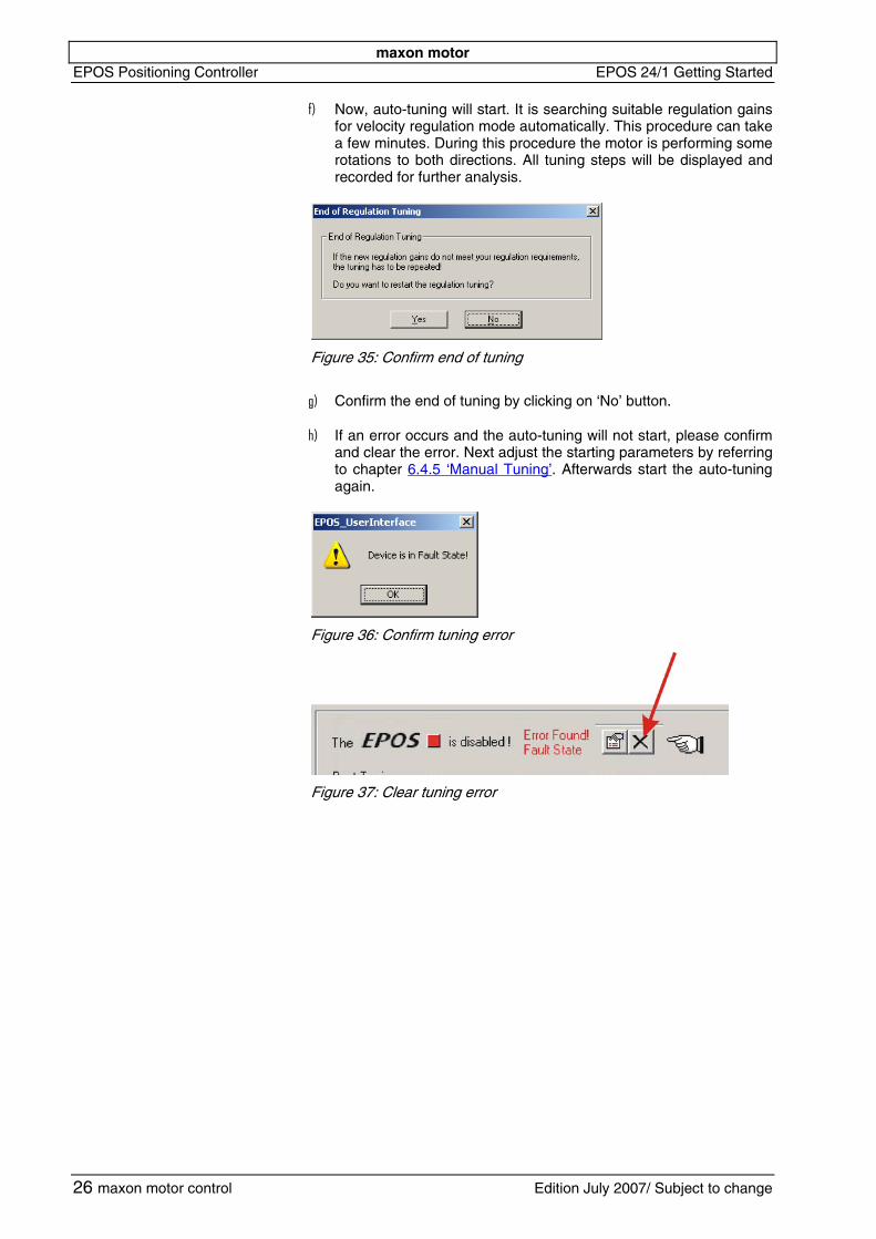
f) Now, auto-tuning will start. It is searching suitable regulation gains
for velocity regulation mode automatically. This procedure can take a few minutes. During this procedure the motor is performing some rotations to both directions. All tuning steps will be displayed and recorded for further analysis.
g)
h)
Figure 35: Confirm end of tuning
Confirm the end of tuning by clicking on ‘No’ button.
If an error occurs and the auto-tuning will not start, please confirm and clear the error. Next adjust the starting parameters by referring to chapter 6.4.5 ‘Manual Tuning’. Afterwards start the auto-tuning again.
Figure 36: Confirm tuning error
Figure 37: Clear tuning error
26 maxon motor control Edition July 2007/ Subject to change
maxon motor EPOS 24/1 Getting Started EPOS Positioning Controller
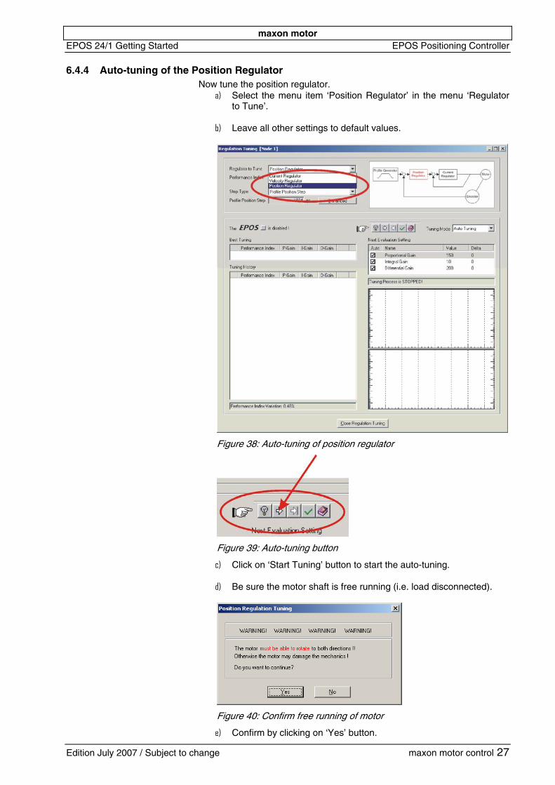
6.4.4 Auto-tuning of the Position Regulator Now tune the position regulator.
a)
b)
Select the menu item ‘Position Regulator’ in the menu ‘Regulator to Tune’.
Leave all other settings to default values.
Figure 38: Auto-tuning of position regulator
c)
d)
Figure 39: Auto-tuning button
Click on ‘Start Tuning’ button to start the auto-tuning.
Be sure the motor shaft is free running (i.e. load disconnected).
e)
Figure 40: Confirm free running of motor
Confirm by clicking on ‘Yes’ button.
Edition July 2007 / Subject to change maxon motor control 27
maxon motor EPOS Positioning Controller EPOS 24/1 Getting Started
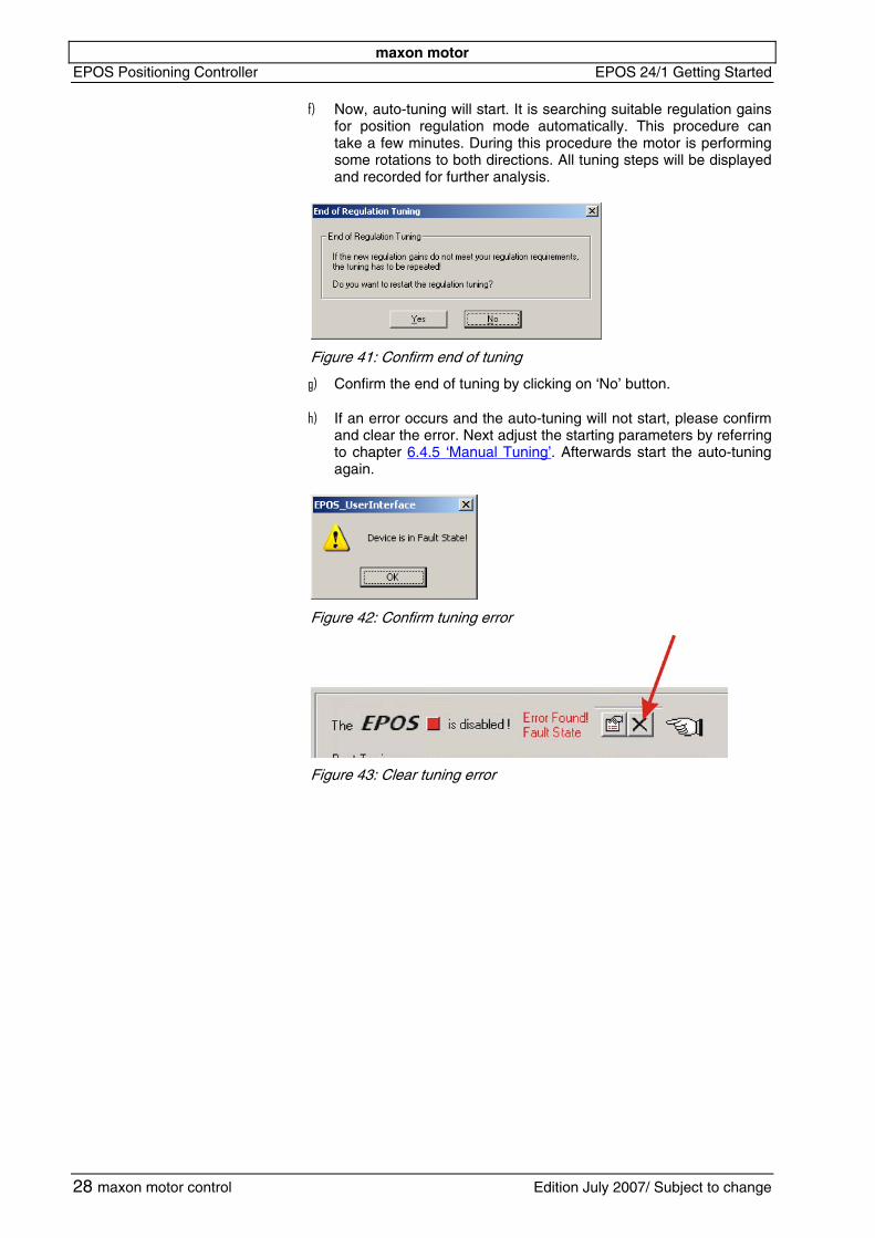
f) Now, auto-tuning will start. It is searching suitable regulation gains
for position regulation mode automatically. This procedure can take a few minutes. During this procedure the motor is performing some rotations to both directions. All tuning steps will be displayed and recorded for further analysis.
g)
h)
Figure 41: Confirm end of tuning
Confirm the end of tuning by clicking on ‘No’ button.
If an error occurs and the auto-tuning will not start, please confirm and clear the error. Next adjust the starting parameters by referring to chapter 6.4.5 ‘Manual Tuning’. Afterwards start the auto-tuning again.
Figure 42: Confirm tuning error
Figure 43: Clear tuning error
28 maxon motor control Edition July 2007/ Subject to change
maxon motor EPOS 24/1 Getting Started EPOS Positioning Controller
6.4.5 Manual Tuning If the auto-tuning shows an error or the result of the auto-tuning is not sufficient, you have to tune the appropriate regulator manually. You have to start an iterative search of the regulation gains. Change the system parameters manually, start a single step movement and check the recorded data. Follow the next instructions:
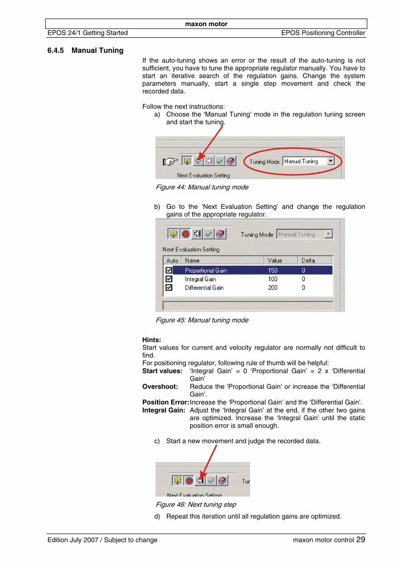
a) Choose the ‘Manual Tuning’ mode in the regulation tuning screen and start the tuning.
Figure 44: Manual tuning mode
b) Go to the ‘Next Evaluation Setting’ and change the regulation
gains of the appropriate regulator.
Figure 45: Manual tuning mode
Hints: Start values for current and velocity regulator are normally not difficult to find. For positioning regulator, following rule of thumb will be helpful: Start values: ‘Integral Gain’ = 0 ‘Proportional Gain’ = 2 x ‘Differential
Gain’ Overshoot: Reduce the ‘Proportional Gain’ or increase the ‘Differential
Gain’. Position Error: Increase the ‘Proportional Gain’ and the ‘Differential Gain’. Integral Gain: Adjust the ‘Integral Gain’ at the end, if the other two gains
are optimized. Increase the ‘Integral Gain’ until the static position error is small enough.
c) Start a new movement and judge the recorded data.
Figure 46: Next tuning step
d) Repeat this iteration until all regulation gains are optimized.
Edition July 2007 / Subject to change maxon motor control 29
maxon motor EPOS Positioning Controller EPOS 24/1 Getting Started
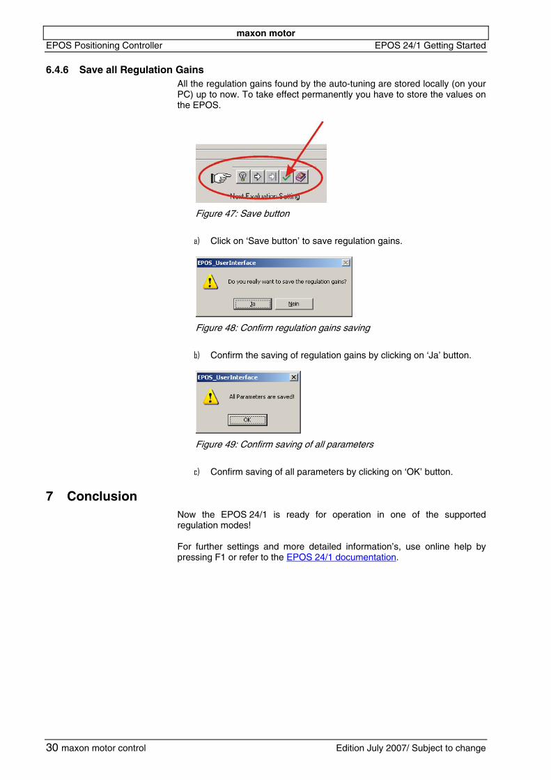
6.4.6 Save all Regulation Gains All the regulation gains found by the auto-tuning are stored locally (on your PC) up to now. To take effect permanently you have to store the values on the EPOS.
a)
Figure 47: Save button
Click on ‘Save button’ to save regulation gains.
b)
Figure 48: Confirm regulation gains saving
Confirm the saving of regulation gains by clicking on ‘Ja’ button.
c)
Figure 49: Confirm saving of all parameters
Confirm saving of all parameters by clicking on ‘OK’ button.
7 Conclusion Now the EPOS 24/1 is ready for operation in one of the supported regulation modes! For further settings and more detailed information’s, use online help by pressing F1 or refer to the EPOS 24/1 documentation.
30 maxon motor control Edition July 2007/ Subject to change