Embed Size (px)
Citation preview
© 2010, TSI Incorporated
Volumetric 3-Component Velocimetry (V3V)
© 2010, TSI Incorporated
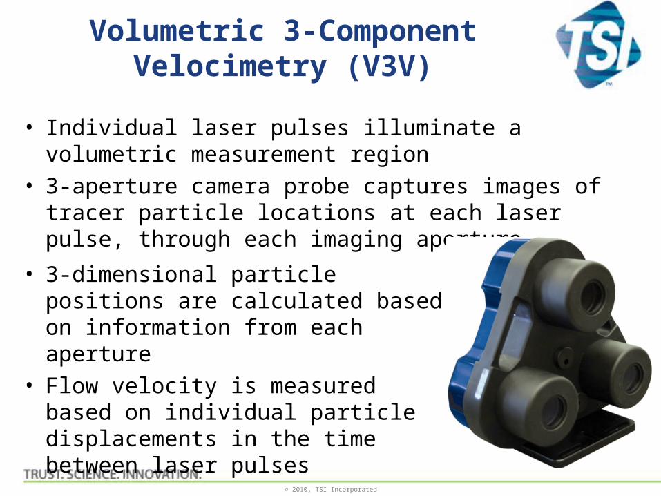
Volumetric 3-Component Velocimetry (V3V)
• Individual laser pulses illuminate a volumetric measurement region
• 3-aperture camera probe captures images of tracer particle locations at each laser pulse, through each imaging aperture
• 3-dimensional particle positions are calculated based on information from each aperture
• Flow velocity is measured based on individual particle displacements in the time between laser pulses
© 2010, TSI Incorporated
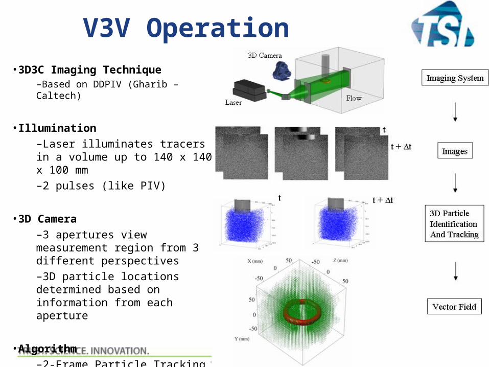
V3V Operation•3D3C Imaging Technique
–Based on DDPIV (Gharib – Caltech)
•Illumination
–Laser illuminates tracers in a volume up to 140 x 140 x 100 mm
–2 pulses (like PIV)
•3D Camera
–3 apertures view measurement region from 3 different perspectives
–3D particle locations determined based on information from each aperture
•Algorithm
–2-Frame Particle Tracking
–Velocity is based on individual particle displacements in the time between laser pulses
© 2010, TSI Incorporated
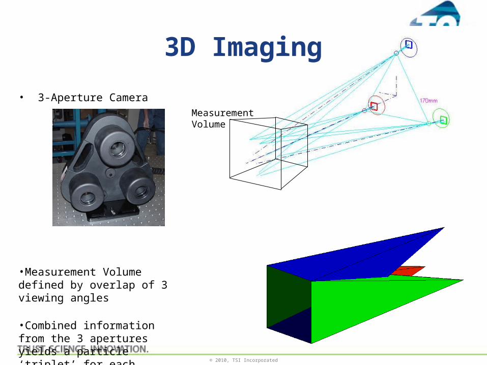
• 3-Aperture Camera
•Measurement Volume defined by overlap of 3 viewing angles
•Combined information from the 3 apertures yields a particle ‘triplet’ for each particle in the common viewing area.
3D Imaging
MeasurementVolume
© 2010, TSI Incorporated
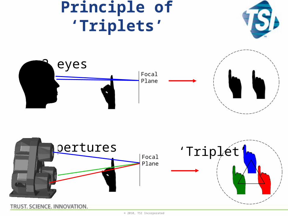
Principle of ‘Triplets’
FocalPlane
FocalPlane
2 eyes
3 apertures ‘Triplet’

© 2010, TSI Incorporated
3D Camera Calibration
• Automated Multi-plane Calibration • Capture calibration target images in z-planes parallel to the camera.
– Find the target center in each plane to correct misalignment error
– Find dewarping polynomials in each plane to correct lens distortion
– Find pixel adjustment factor in each plane to correct pinhole deviation.Triplet size at each calibration plane
© 2010, TSI Incorporated
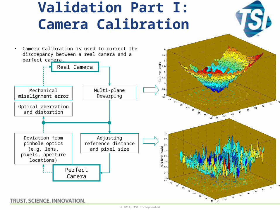
Validation Part I: Camera Calibration
• Camera Calibration is used to correct the discrepancy between a real camera and a perfect camera.
Real Camera
Perfect Camera
Mechanical misalignment error
Optical aberration and distortion
Deviation from pinhole optics (e.g. lens, pixels,
aperture locations)
Adjusting reference distance and pixel size
Multi-plane Dewarping
© 2010, TSI Incorporated
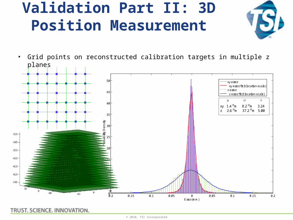
Validation Part II: 3D Position Measurement
• Grid points on reconstructed calibration targets in multiple z planes
-0.2 -0.15 -0.1 -0.05 0 0.05 0.1 0.15 0.20
5
10
15
20
25
30
35
40
45
50
Error (mm)
Pro
ba
bili
ty D
en
sity
xy error xy error fit (t location-scale)z error z error fit (t location-scale)
xy 1.4 m 8.2 m 3.24z 2.6 m 37.2 m 5.00
© 2010, TSI Incorporated
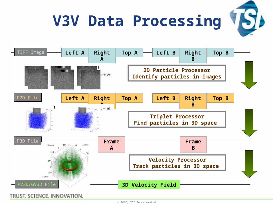
V3V Data Processing
Right A
Left A Top A Right B
Left B Top B
Frame A
2D Particle ProcessorIdentify particles in images
Frame B
Right A
Left A Top A Right B
Left B Top B
Triplet ProcessorFind particles in 3D space
Velocity ProcessorTrack particles in 3D space
TIFF Image
3D Velocity Field
P2D File
P3D File
PV3D/GV3D File
© 2010, TSI Incorporated
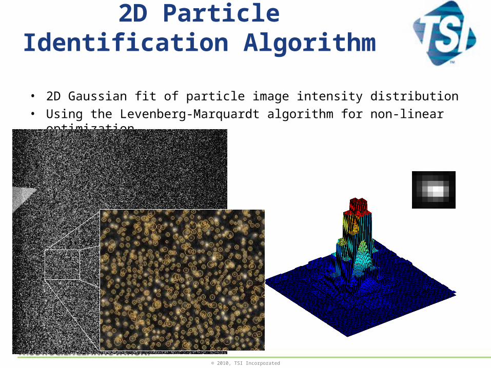
2D Particle Identification Algorithm
• 2D Gaussian fit of particle image intensity distribution
• Using the Levenberg-Marquardt algorithm for non-linear optimization
© 2010, TSI Incorporated
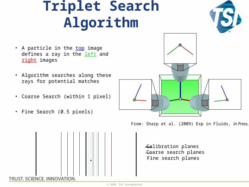
Triplet Search Algorithm
• A particle in the top image defines a ray in the left and right images
• Algorithm searches along these rays for potential matches
• Coarse Search (within 1 pixel)
• Fine Search (0.5 pixels)
Calibration planesCoarse search planesFine search planes
From: Sharp et al. (2009) Exp in Fluids, in Press.
© 2010, TSI Incorporated
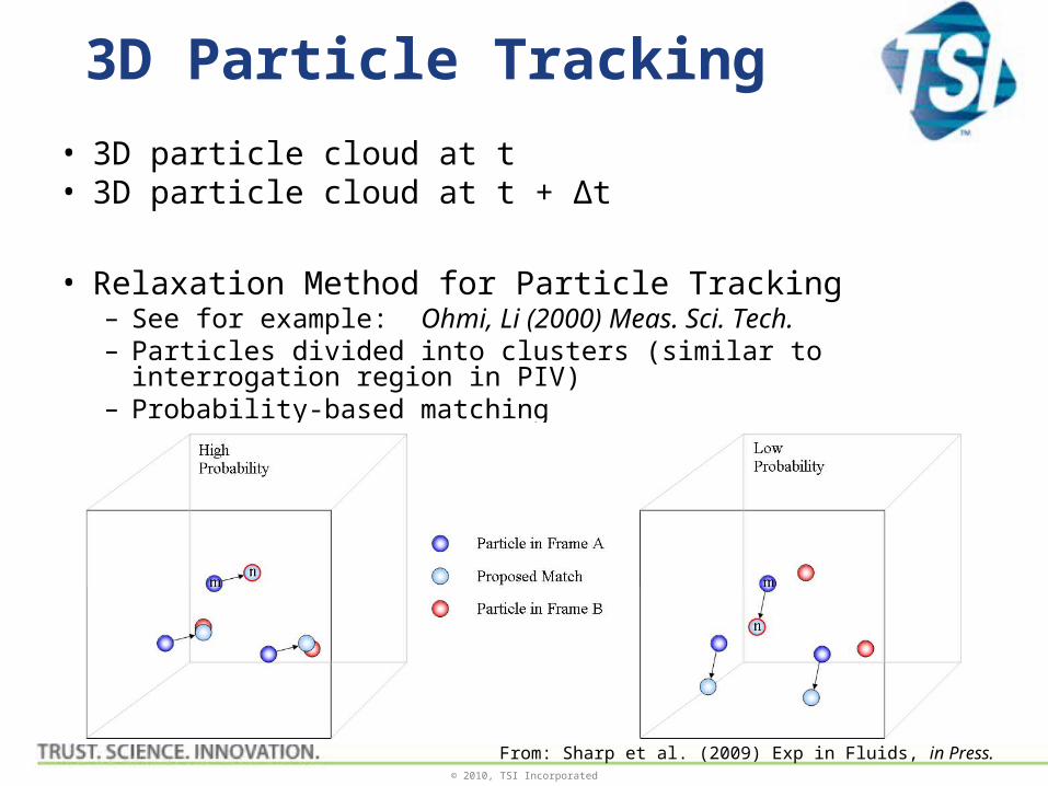
3D Particle Tracking
• 3D particle cloud at t• 3D particle cloud at t + Δt
• Relaxation Method for Particle Tracking– See for example: Ohmi, Li (2000) Meas. Sci. Tech.– Particles divided into clusters (similar to interrogation region in PIV)– Probability-based matching
From: Sharp et al. (2009) Exp in Fluids, in Press.
© 2010, TSI Incorporated
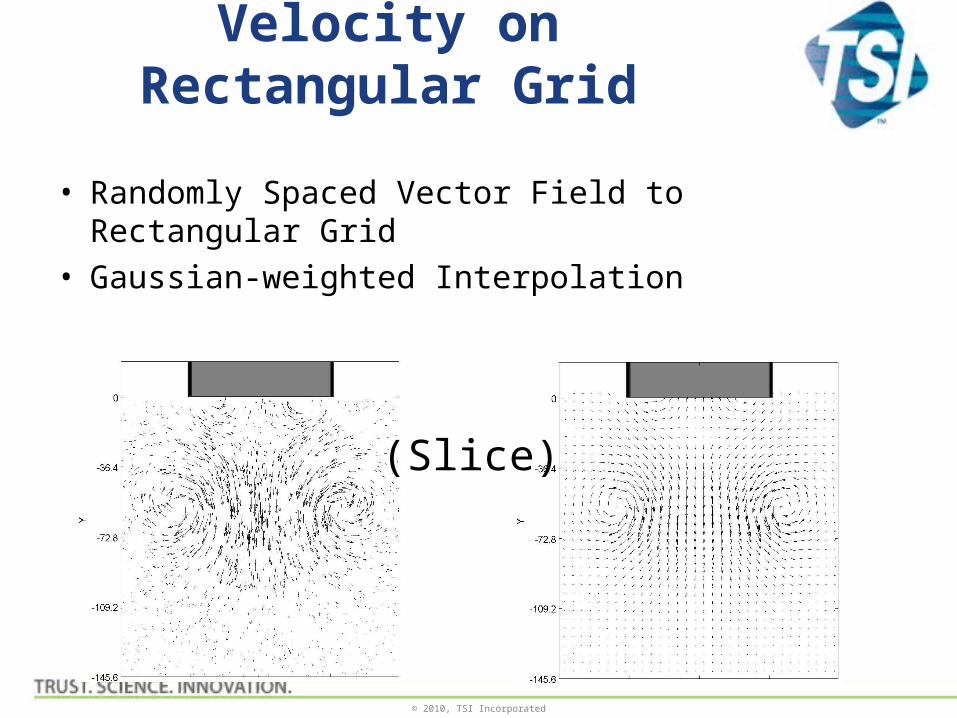
Velocity on Rectangular Grid
• Randomly Spaced Vector Field to Rectangular Grid
• Gaussian-weighted Interpolation
(Slice)
© 2010, TSI Incorporated
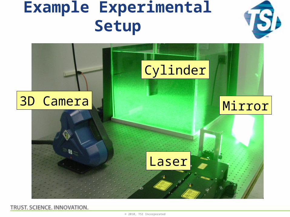
Example Experimental Setup
Cylinder
Laser
3D Camera Mirror
© 2010, TSI Incorporated
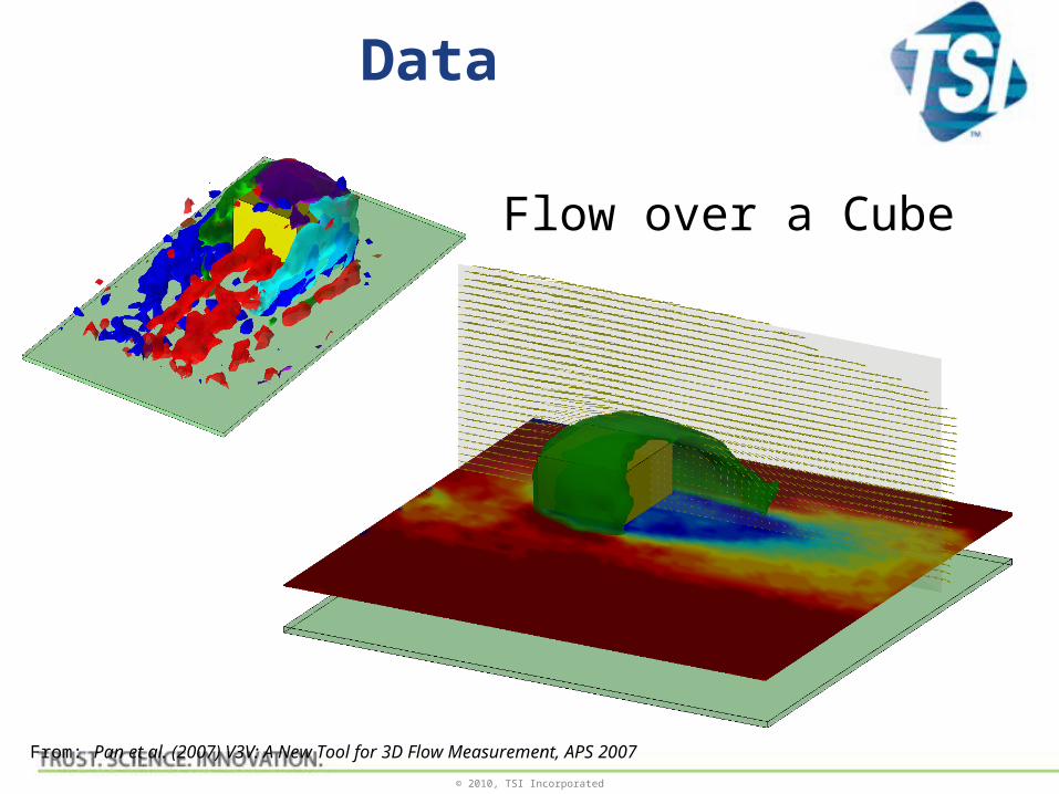
Data
Flow over a Cube
From: Pan et al. (2007) V3V: A New Tool for 3D Flow Measurement, APS 2007
© 2010, TSI Incorporated
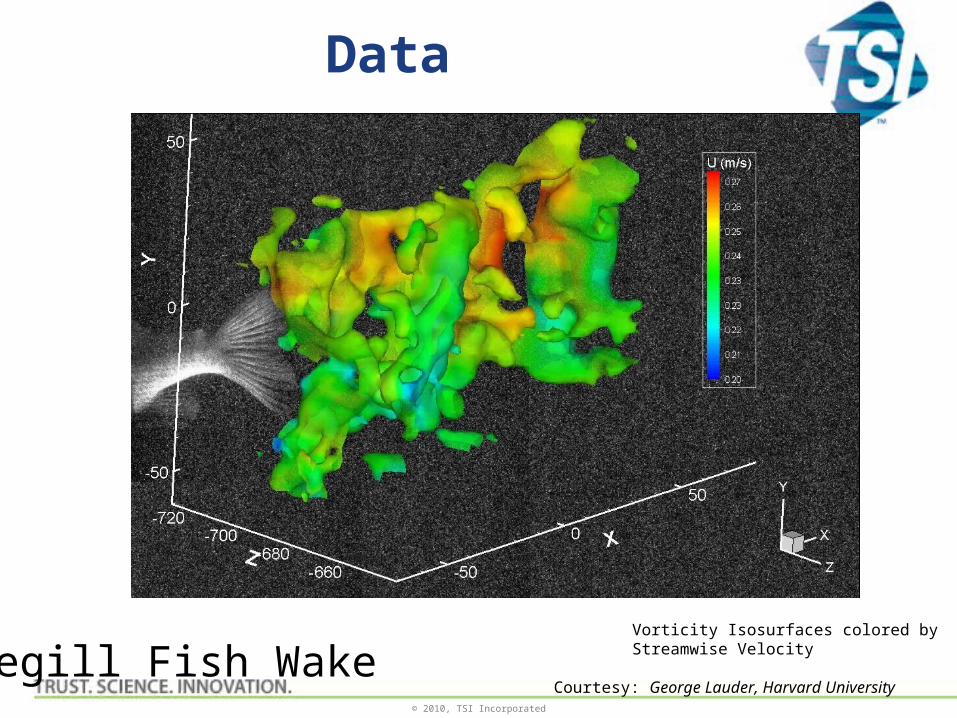
Data
Bluegill Fish Wake Vorticity Isosurfaces colored by Streamwise Velocity
Courtesy: George Lauder, Harvard University
© 2010, TSI Incorporated
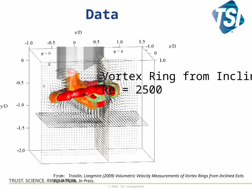
Data
Vortex Ring from Inclined ExitRe = 2500
From: Troolin, Longmire (2009) Volumetric Velocity Measurements of Vortex Rings from Inclined ExitsExp in Fluids, In Press.
© 2010, TSI Incorporated
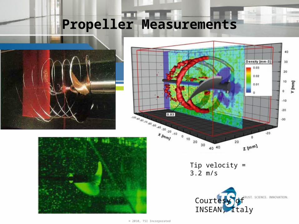
Propeller Measurements
Tip velocity = 3.2 m/s
Courtesy of INSEAN, Italy

© 2010, TSI Incorporated
Mixer with Rushton Turbine
Courtesy of Penn State U
© 2010, TSI Incorporated
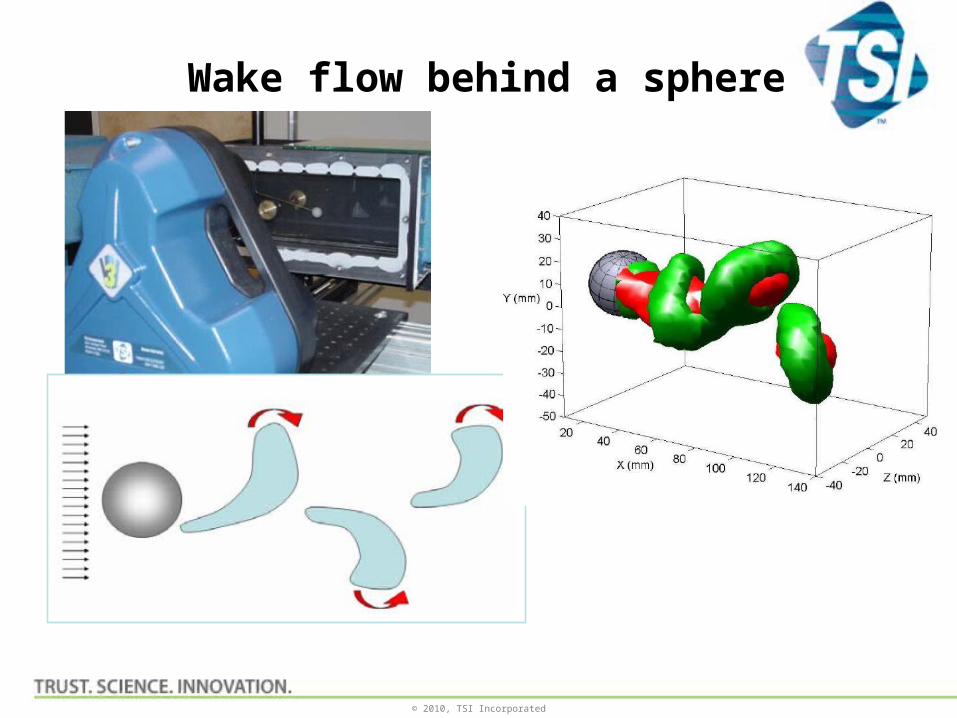
Wake flow behind a sphere
© 2010, TSI Incorporated
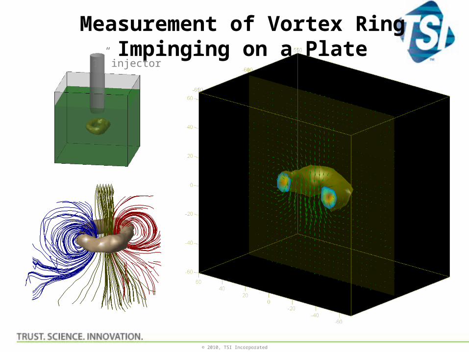
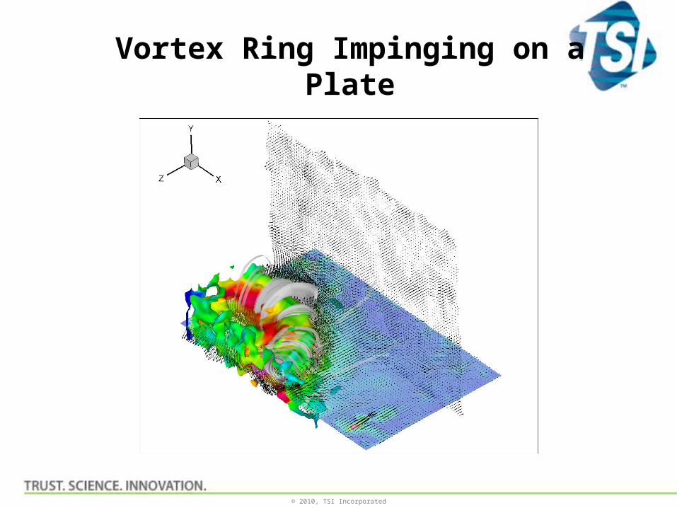
Measurement of Vortex Ring Impinging on a Plate
1” injector
© 2010, TSI Incorporated
Vortex Ring Impinging on a Plate
© 2010, TSI Incorporated
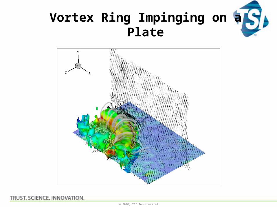
Vortex Ring Impinging on a Plate
© 2010, TSI Incorporated
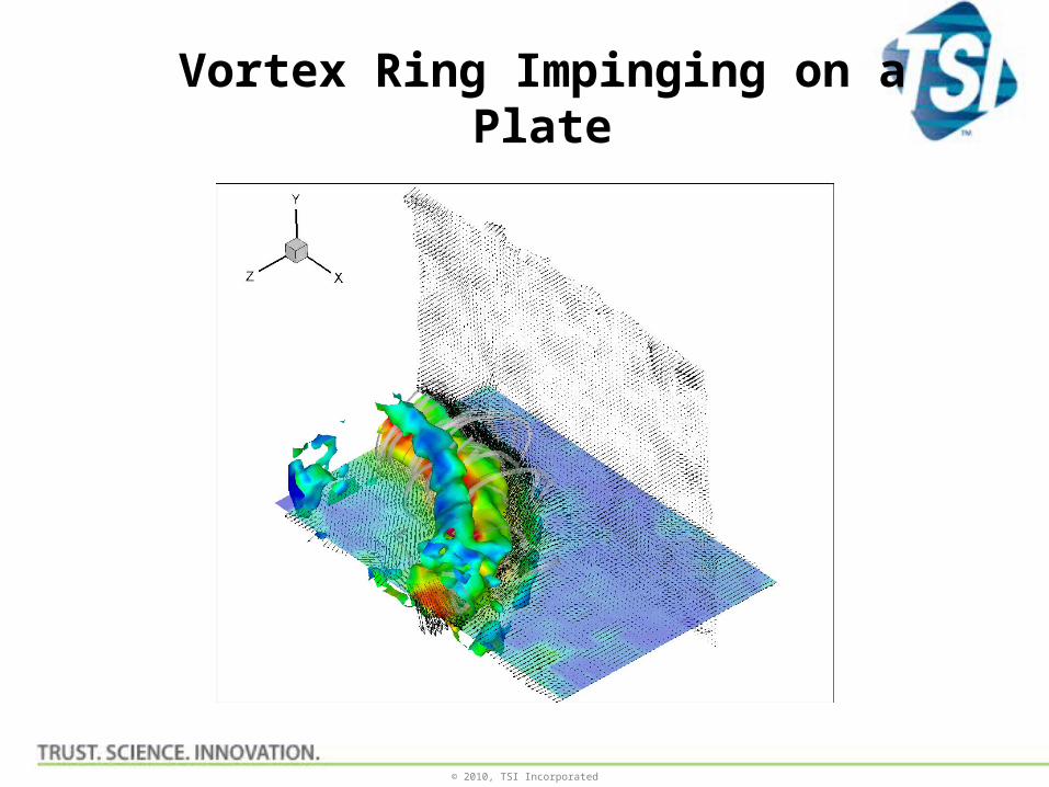
Vortex Ring Impinging on a Plate
© 2010, TSI Incorporated
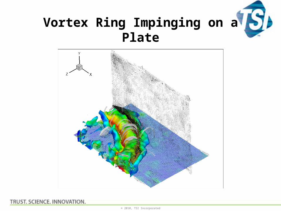
Vortex Ring Impinging on a Plate