Embed Size (px)
Citation preview

© 2
01
0 B
en
tley
Syst
em
s, In
corp
ora
ted
Integrating the Plant Design Processfor Structural Engineers
Mitch Sklar, Technical Director, Structural Products
POYRY

© 2
010
Bent
ley
Syst
ems,
Inco
rpor
ated
2 | WWW.BENTLEY.COM
Interoperability
Analysis & Design
Analyze
Detailing & Fabrication
Augment
Modeling & Documentation
Deliverable Publishing
View
Content Management
Project Review

© 2
010
Bent
ley
Syst
ems,
Inco
rpor
ated
3 | WWW.BENTLEY.COM
iWare Apps
Bentley's Free Software Serving Infrastructure Professionals.
Software Interoperability Is Crucial To The Successful, Cost-effective Design, Delivery, & Operation Of Infrastructure.
Http://www.Bentley.Com/En-us/Free+software/

© 2
010
Bent
ley
Syst
ems,
Inco
rpor
ated
4 | WWW.BENTLEY.COM
What is the Structural Dashboard?
The Dashboard is a free tool that assists in managing the data & workflow of projects from start to finish.
The Dashboard provides a Single Interface to learn how Bentley’s comprehensive products integrate together in more efficient project workflows.
It also a useful Launch Pad & Web Portal for easy access to any information on Bentley’s structural products, RSS News Feeds, Be Community Blogs & Forums, SELECT software downloads, support & sales.

© 2
010
Bent
ley
Syst
ems,
Inco
rpor
ated
5 | WWW.BENTLEY.COM
Benefits of the Structural Dashboard Easy access to open
“recently opened model files” for any installed structural product
Project Folder & File management filtered by structural product
Quick links to Be Community website, log a support issue, contact Bentley Sales or SELECT
Real-time RSS News Feeds Project Notes include quick
links to specifications, design documents & project web sites or embed pictures, spreadsheets or add notes like project billing codes, contacts
All latest Product Versions

© 2
010
Bent
ley
Syst
ems,
Inco
rpor
ated
6 | WWW.BENTLEY.COM
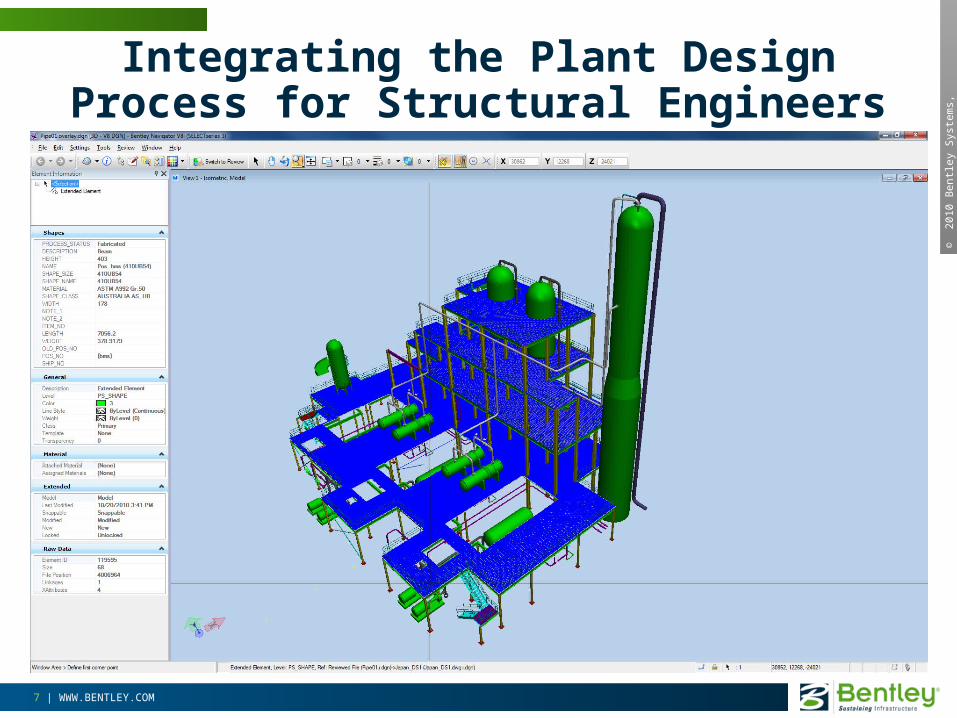
New Dashboard DGN Viewer• View Basic, i-Model or ISM DGN Models
• Navigate, Search, Isolate & Measure Components
© 2
010
Bent
ley
Syst
ems,
Inco
rpor
ated
7 | WWW.BENTLEY.COM
Integrating the Plant Design Process for Structural Engineers

© 2
010
Bent
ley
Syst
ems,
Inco
rpor
ated
9 | WWW.BENTLEY.COM
Structural Engineer Pipe Stress Engineer
Pipe Supports(Type, Loads, Location)
Piping Designer
How do EPC’s Work Today?

© 2
010
Bent
ley
Syst
ems,
Inco
rpor
ated
10 | WWW.BENTLEY.COM
How do EPC’s Work Today?
“A manual approach to managing these piping loads begins with analysis of the piping system to locate supports, guides, & anchor points.
After the analysis is complete the piping engineer sorts through the piping support reactions to find the critical cases that the supports/ structure must be designed for.
These forces are hand marked on a multiple piping isometric drawings; with one copy given to the piping designer to complete the PDS piping model, locations of pipe shoes, guides, anchor points, etc; and Another copy given to the structural engineer for designing the supporting structures.
While working in PDS / FrameWorks the structural engineer would build the structural model incorporating all the required pipe supports. To prepare the structural model for analysis the engineer must then search each isometric finding the support points and associated loads evaluate and apply them to the structural model.
“The biggest problem here is that a single process structure may have hundreds or thousands of piping isometric drawings associated with it, resulting in a vast amount of paper and manual evaluation. This is very inefficient and time consuming.”

© 2
010
Bent
ley
Syst
ems,
Inco
rpor
ated
11 | WWW.BENTLEY.COM
The Typical way of working as a Structural Engineer is somewhat, if not all, Fragmented
OtherTools, Software,
& Techniques
ConstructionDocumentation
Structural Analysis &
Design
Proprietary File Formats(fragmented)
Industry Standards (fragmented)
3D Plant DesignPipe Stress
Analysis
Project Data &Deliverables

© 2
010
Bent
ley
Syst
ems,
Inco
rpor
ated
12 | WWW.BENTLEY.COM
Problem Is Consistent Across The Plant Market
• EPC # 2 – “There are some significant disconnects between the pipe stress and the structural engineers. When conveying information from pipe stress to Structural, we typically provide the preliminary structural steel drawings to pipe stress for them to mark up loads on it. This is extremely inefficient. Also, piping should try to get as much structural steel put onto the steel drawings so that detailing, fabrication and erection can be done in a single pass”
• EPC # 3 – We have some serious frustrations in the way piping designers do their work, interfacing with structural and mechanical. I know the current process is disjointed, but it is all our tools provide us.”
• EPC #4 - We have standard loadings that take care of the major stuff. The thing that is a killer is the special case stuff. The thermal loads and piping movements, spring supports, anchor points etc; these types of things have special details, as well as high loads. In addition, a structural engineer can’t guess where these things are going to be or what they will look like. This has to come from the Piping Engineer and we have to sort through drawings. Most of the time this info gets to structural at best just before you issue the drawings. Sometimes it is after the first fabrication release has been sent out and you have to revise the drawings.
© 2
010
Bent
ley
Syst
ems,
Inco
rpor
ated
13 | WWW.BENTLEY.COM
What if, as a structural engineer, you could receive quality data from the 3D plant model and the pipe stress model, and link these to your structural analysis and design model…
Starting with the Structural Analysis Model …Including the Foundations (mats, pile caps, combined, pad)…Including the Connections (gussets, moment, base plates, prequalified)…Accounting for the various Codes (wind, seismic, load combos)Combined with the Support information from the Pipe Stress Model Develop the Steel/Concrete Design Documentation Deliverables
... to automatically create and maintain the engineering drawings, schedules, foundation designs, connection designs, piping isometrics, and more?
…How could that impact your work and bottom line?
Why do we want to have Integration Across Disciplines? Why do we want to Share or have Continuity of Information?

© 2
01
0 B
en
tley
Syst
em
s, In
corp
ora
ted
Interoperability with Bentley Navigator,STAAD, AutoPIPE, and ProStructures

© 2
010
Bent
ley
Syst
ems,
Inco
rpor
ated
15 | WWW.BENTLEY.COM
Bentley Integrated Structural and CAE Solution
OtherTools, Software,
& Techniques
OpenPLANT,AutoPLANT
ProStructures
AutoPIPE
STAADProject Data &Deliverables

© 2
010
Bent
ley
Syst
ems,
Inco
rpor
ated
16 | WWW.BENTLEY.COM
Bentley Integrated Structural and CAE Solution
AutoPLANTOpenPLANT
AutoPIPE Nozzle, StressISO, PlantFlow,
Puls
Foundations, Connections, Advance Analysis, & Offshore
AutoPIPE
STAAD
ProSteel, ProConcrete ProStructures
Project Data & Deliverables

© 2
01
0 B
en
tley
Syst
em
s, In
corp
ora
ted
Let’s See the Interoperability between STAAD, AutoPIPE, and ProStructures…

© 2
010
Bent
ley
Syst
ems,
Inco
rpor
ated
18 | WWW.BENTLEY.COM
DataIntegration
DataIntegration
Bi-Directional Exchange
Bi-Directional Exchange
AutoPIPE…CAE Pipe Stress Analysis & Integration
Data Export

© 2
010
Bent
ley
Syst
ems,
Inco
rpor
ated
19 | WWW.BENTLEY.COM
Bi-Directional Exchange
Data Export Data Export
Data Export
Data Export*
AutoPIPE Modeling Interoperability

© 2
010
Bent
ley
Syst
ems,
Inco
rpor
ated
20 | WWW.BENTLEY.COM
Bi-Directional Exchange
Bi-Directional Exchange
Data Integration
Data Integration
STAAD…Structural Analysis & Design Integration

© 2
010
Bent
ley
Syst
ems,
Inco
rpor
ated
21 | WWW.BENTLEY.COM
STAAD…Modeling Interoperability
Bi-Directional ExchangePartial DataIntegration**
Data Import/Export**
Data Export*
Data Export

© 2
010
Bent
ley
Syst
ems,
Inco
rpor
ated
22 | WWW.BENTLEY.COM
ProSteel
3D-Structural Steel Modeling and Detailing
for AutoCAD and MicroStation
ProConcrete
3D-Structural Concrete Modeling and Detailing
for AutoCAD
ProStructures
Bentley’s ProStructures is the combination of ProSteel & ProConcrete. For advanced 3D Modeling, Documentation, & Detailing of
Steel and Concrete Structures
ProStructures

© 2
010
Bent
ley
Syst
ems,
Inco
rpor
ated
23 | WWW.BENTLEY.COM
AutoCAD and
MicroStation
Bill of
Materials &
Schedules
CNC/DSTV
Fabrication
Customized
Platework
Modeling &
Documentation for
Steel\Concrete
Clash Detection
Reinforcement
Detailing
Cast in Place
& PreCast
Concrete
ProStructures Capabilities
Engineering/
Fabrication
Drawings

© 2
010
Bent
ley
Syst
ems,
Inco
rpor
ated
24 | WWW.BENTLEY.COM
•Faster Design Combined structure + piping model w/changed piping loads automatically updated multiple times in STAAD
•Structural Sway and StiffnessCombined structure + piping model to analyze true combined stiffness
•Less Assumptions
More accurate pipe support& equipment loads + realistic structural and piping design stresses
•Cost SavingsAvoid costly re-design and construction delays
AutoPIPE - STAAD Integration
Bi-Directional Exchange
Single-User IntegratedPiping/Structure
Models

© 2
010
Bent
ley
Syst
ems,
Inco
rpor
ated
25 | WWW.BENTLEY.COM
Multi-User AutoPIPE
·Faster Design transfer piping and support loads in hours not weeks
·Structural Sway and Stiffness considerations for more accurate designs
·Less Assumptionsleading to safer structure, piping, and equipment
·Cost Savingspotential on pipe supportsand structure
STAAD ModelImport & Manage Multiple AutoPIPE & STAAD model
changes & results
Model 1, Line 1
Model 2, Line 2
Model 3, Line 3
Model 4, Line 4
Multi-User IntegratedPiping/Structure
Models
AutoPIPE - STAAD Integration

© 2
010
Bent
ley
Syst
ems,
Inco
rpor
ated
26 | WWW.BENTLEY.COM
STAAD - ProStructures Integration
Complete Bi-Directional Workflow
Complete Steel and Concrete Solution

© 2
010
Bent
ley
Syst
ems,
Inco
rpor
ated
27 | WWW.BENTLEY.COM
Bentley Navigator
Open
Measure
Manipulate
Simulate
ExploreMarkup
Find
Group
Produce
Measuring2D & 3D Navigation
Dynamic Sectioning
Markup Redline
Data Interrogation
Rendering Animation
Print Paper / PDF
Clash Detection Schedule Simulation

© 2
010
Bent
ley
Syst
ems,
Inco
rpor
ated
28 | WWW.BENTLEY.COM
AutoPIPE & Navigator Hot Clash DetectionTo Avoid Design Mistakes and Operation Failure
AutoPIPE
Bentley Navigator
Aug 2011

© 2
010
Bent
ley
Syst
ems,
Inco
rpor
ated
29 | WWW.BENTLEY.COM
Bentley Navigator for the iPADUnmanaged view, query & mark-up
MicroStation or i-model Composer
optimized i-model
enhancement
DropBox, email, i-tunes
etc.
Optimised
for iPad
Mark-ups
Optimised
for iPad
JAN 20
12

© 2
010
Bent
ley
Syst
ems,
Inco
rpor
ated
30 | WWW.BENTLEY.COM
ProjectWise
Optimised
for iPad
MicroStation or i-model Composer
optimized i-model
enhancement
ProjectWiseExplorer
Packaging i-model
enhancement
DropBox, email, i-tunes
etc.
SET
ProjectWise Explorer for the iPADManaged mobile dynamic synchronisation
JAN 20
12

© 2
010
Bent
ley
Syst
ems,
Inco
rpor
ated
31 | WWW.BENTLEY.COM
Structural/Piping Interoperability Benefits
Fragmented Approach
• Engineers build 2D (LAC) Structure/Piping models of their project for Analysis
• Designers build a second matching 2D/3D model to incorporate elevations, sections, and details
• Engineers would re-analyze and re-evaluate their individual design elements, and manually submit changes back to the designers for updating
Integrated Workflow
• Interoperability allows the design and engineering processes to be optimized and efficient, as both teams share the same 3D Modeling Environment
• Engineers, can import the 3D models and supplement them with member/material properties before proceeding with the engineering analysis
• Modifications to the model may/will still be required; Real Time Design Reviews allows project savings and efficiencies by working with one model and eliminating duplicate work
• Designers/Engineers can analyze, evaluate and perform sensitivity studies on the integrated Structural/Piping Systems

© 2
01
0 B
en
tley
Syst
em
s, In
corp
ora
ted
Integrating the Plant Design Processfor Structural Engineers Thank You!
Mitch Sklar, Director, Sales Technical Support


![Scientology Sklar Case 2009 SupremeCt Writ S.Ct.08-9180-Sklar-Cert_Petition[1]](https://img.pdfslide.us/doc/110x75/577dabcd1a28ab223f8cfa99/scientology-sklar-case-2009-supremect-writ-sct08-9180-sklar-certpetition1.jpg)