Embed Size (px)
Citation preview

© 2009 Collier Research Corp.
Workshop on Multiscale Modeling of CompositesJuly 24-25, 2009
Collier Research Corporation Newport News, VA
Multi-Scale Methods in HyperSizer for Design, Analysis and Structural Sizing
© 2009 Collier Research Corporation
Overview
• HyperSizer as a multi-scale environment
• Integration with Global Vehicle FEA
• Integration with Micromechanics
• Ongoing Research• Variational Multiscale Cohesive Method VMCM
• Progressive Damage using Shapery Theory

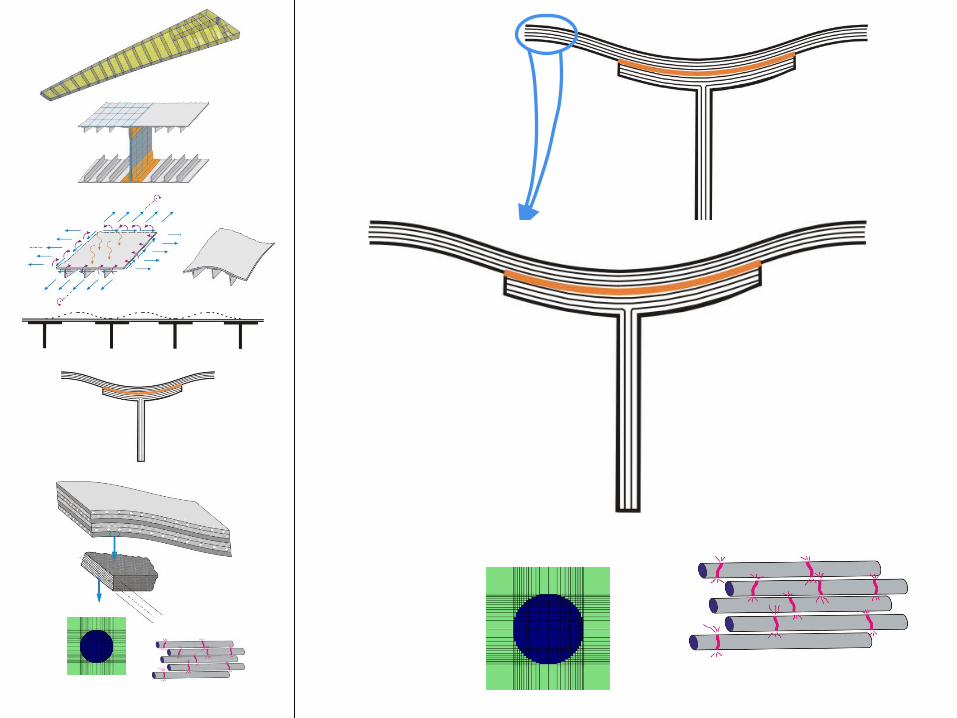
HyperSizer as a Multiscale Envoronment
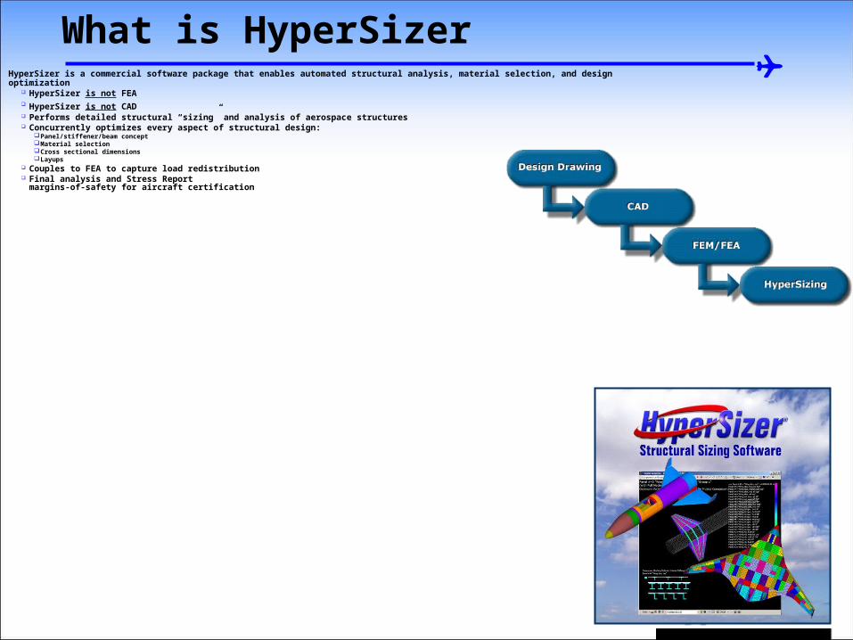
What is HyperSizer
HyperSizer is a commercial software package that enables automated structural analysis, material selection, and design optimization HyperSizer is not FEA HyperSizer is not CAD Performs detailed structural “sizing” and analysis of aerospace structures Concurrently optimizes every aspect of structural design:
Panel/stiffener/beam conceptMaterial selectionCross sectional dimensionsLayups
Couples to FEA to capture load redistribution Final analysis and Stress Report
margins-of-safety for aircraft certification

Modeled as a surface of 2D shell elements (NASTRAN CQUAD4)
Modeled as a line of 1D beam elements (NASTRAN CBAR)
Joint between substructure to surface skin
- wing spar to OML stiffened panel
Joint between surface skin and panel stiffener
- flange bond line


-
σ33
σxx, σyy, σzz
τxy, τxz, τyz
σ11, σ22, σ33
τ12, τ13, τ23
at every ply depth
transformed to ply direction
-τxz
-τ23
-σzz
An example ply from Top Adherend (all plies analyzed)
An example ply from Bottom Adherend (all plies analyzed)
Adhesive Layer
-τ23
-
σ33

-
σ33
-τxz
-τ23
-σzz
-τ23
-
σ33
Out-of-Plane stresses in adherend σ33, τ23, τ13
Computing all six components of stress
σ11, σ22, σ33
τ12, τ13, τ23
for every: - ply- distance increment (> 200 points per ply)
Out-of-Plane stresses in adherend σ33, τ23, τ13
For each of the over 200 points per ply, perform multi-axial stress analysis on the micromechanics Repeating Unit Cell
33
τ23
τ13
τ23τ23
11
22
τ12
σ33σ33
σ22σ22
τ12τ12σ11σ11
In-Plane stresses in adherend σ11, σ22, τ12
In-Plane stresses in adherend σ11, σ22, τ12
τ13
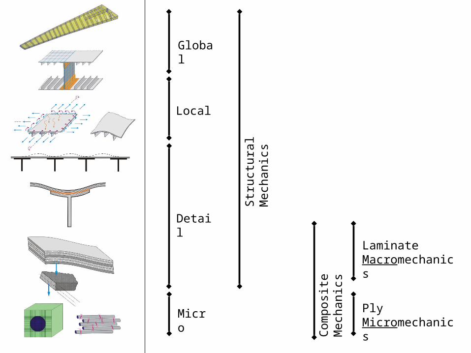
Global
Detail
Local
Str
uctu
ral M
echa
nics
Laminate Macromechanics
Ply Micromechanics
Com
posi
te M
echa
nics
Micro

Integration with a Global FEM

© 2009 Collier Research Corporation
HyperSizer Design Process
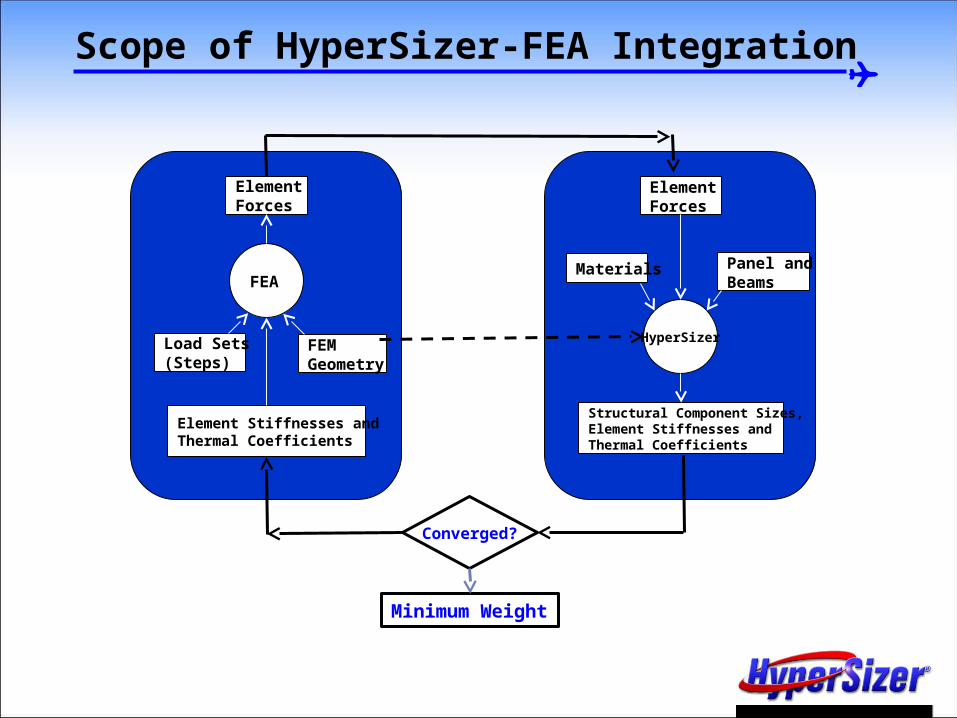
Scope of HyperSizer-FEA Integration
FEA
HyperSizer
Materials Panel and Beams
ElementForces
ElementForces
Structural Component Sizes, Element Stiffnesses and Thermal Coefficients
Load Sets(Steps)
FEMGeometry
Element Stiffnesses and Thermal Coefficients
Converged?
Minimum Weight

Integration with Micromechanics
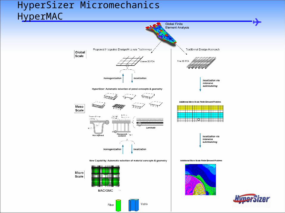
HyperSizer MicromechanicsHyperMAC

Link Established Between HyperSizer and MAC/GMC Materials
Laminate
Ply 1
Ply 2
Ply 3
Ply 4
Matrix 1
Matrix 2
Fiber 1
Fiber 2
HyperSizerHyperSizer with MAC
StiffenedPanel
Laminate
OrthotropicPly
Micro(Fiber-Matrix)
HyperSizer Micromechanics allows the user to graphically “peer” into a structural analysis from the macro to the micro level

HyperSizer Micromechanics ModuleHyperSizer Micromechanics Module
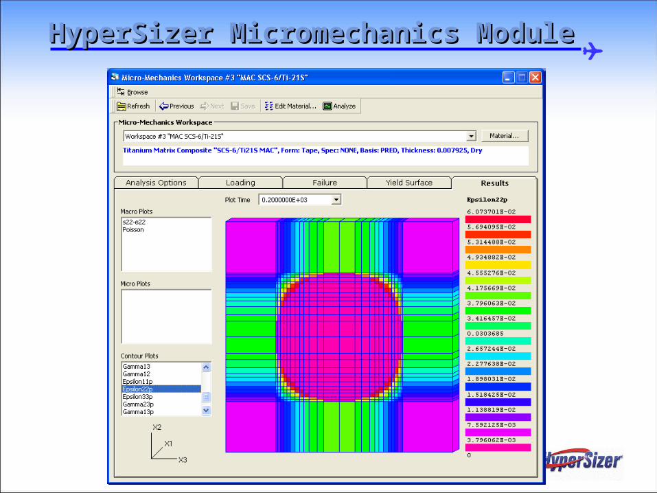
HyperSizer Micromechanics ModuleHyperSizer Micromechanics Module

Ongoing Research
Progressive Failure in Composites

Coupling of HyperSizer with High-Fidelity Analysis Methods
Nx,(Mx, etc)
Nx
Nxy
NxyInitial Crack
Crack Propagation
Stiffeners
The objective is to develop a synergistic coupling between HyperSizer and the Highly Detailed Composite Failure Methods.
© 2009 Collier Research Corporation
• Partnering with University of Michigan to develop accurate methods to predict ultimate and progressive failure in Composites
• Collier Research funding two PhD candidates to develop methods and assist integration into HyperSizer
• Variational Multiscale Cohesive Method (VMCM)• Siva Rudraraju
• Progress Failure with Shapery Theory• Evan Pineda
• Be sure to catch their presentations tomorrow!
Coupling of HyperSizer with High-Fidelity Analysis Methods
Variational Multiscale Cohesive Method (VMCM)
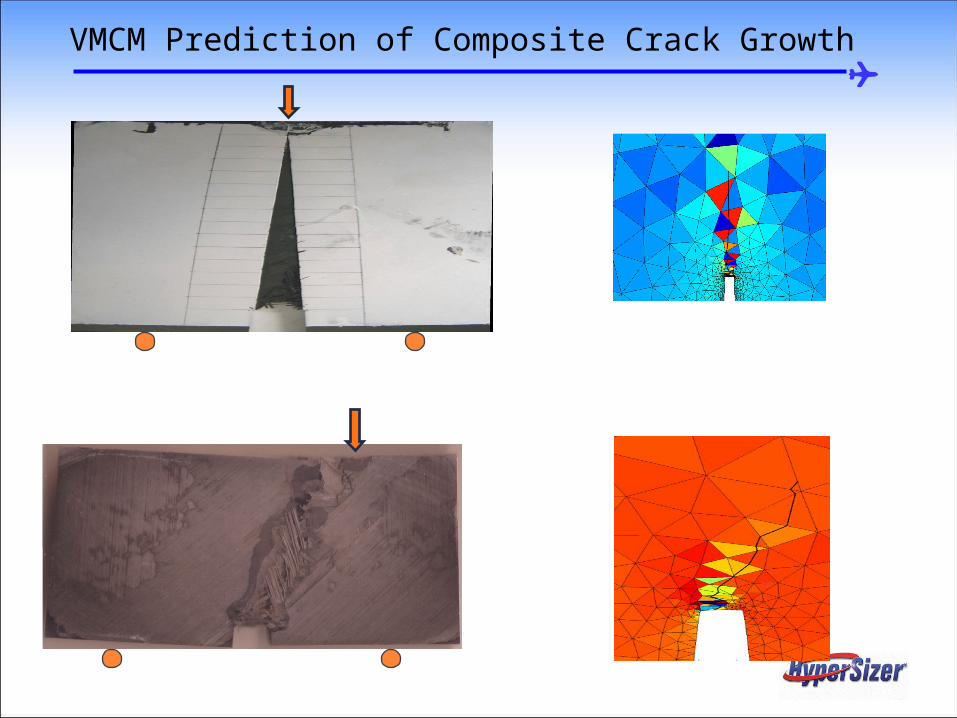
VMCM Prediction of Composite Crack Growth

HyperSizer to VMCM Process
1. Design a stiffened panel structure in HyperSizer using built-in rapid sizing methods
2. Generate a local ABAQUS finite element model of the stiffened panel with user specified crack and all parameters needed for VMCM
3. VMCM will then:a) Predict IF the crack will grow with the given loads, or if
not, at what load level the crack will begin to grow (returns a margin-of-safety)
b) Once the crack begins to grow, determine if it will continue to grow catastrophically or arrest at an adjacent stiffener, etc.
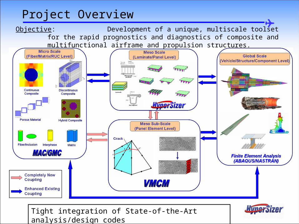
Project Overview
Objective: Development of a unique, multiscale toolset for the rapid prognostics and diagnostics of composite and multifunctional airframe and propulsion structures.
Tight integration of State-of-the-Art analysis/design codes

Progressive Failure using Shapery Theory

27 of 29
Objective
Develop a multiscale analysis tool that captures complicated failure/damage of advanced composite structures using the physics of mechanisms

Coupling between Damage and Failure at the Microscale
© 2008 Collier Research Corporation.
Coupling between damage and failure at the lamina level and the microscale
MAC/GMC
P, Δ
y
x

Conclusions / Summary
HyperSizer is a Multi-Scale Analysis, Design and Sizing Tool working from Global/Vehicle Scale Local Scale Laminate/Layup Scale Micromechanics scale
Continuous Research is being done at every scale to improve robustness, accuracy with the ultimate goal of designing lighter, stronger structures

Backup

A Differential Continuum Damage Model (DCDM) for Fatigue of Unidirectional Composites
I1, I2, I3 are physically meaningful invariants; Max. tran. shear, Max. long. Shear and stress in fiber direction, respectively
• Fatigue Method is included in MAC/GMC, developed at NASA Glenn – Collier’s role is integration with HyperSizer
• Multiaxial,isothermal,transversely isotropic
• Scalar damage variable• Mean stress effect - fatigue limit• Accounts for typical nonlinear
cumulative effects for two level tests and complex block loading programs
• Fatigue and creep damage can be combined in a natural way
• Orientation of fibers relative to load internally accounted for within theory
** Can be extended to include temperature, environmental, probability theory and micro-mechanical effects, (e.g. fiber/matrix bond strength, fiber volume fraction, etc.)

Composite Fatigue Damage Analysis in HyperSizer
Panel
Ply
Constituent
1800
1850
1900
1950
2000
2050
2100
2150
1.E+07 1.E+08 1.E+09
Max
imu
m S
tres
s (M
Pa)
Nf - Cycles to Failure
Predicted Panel S-N Curve
Effects of cyclic loading on composite panel response being incorporated into HyperSizer at constituent level
Panel level cyclic load “block” localized to ply, then MAC/GMC repeating unit cell Calculate and store resulting stress and strain HISTORY for every subcell, for
every ply in stiffened panel DCDM calculates number of load “block” cycles to cause specified local damage
increment calculated This number of cycles applied to entire panel and damage distribution determined New load “block” applied to panel, now local stresses redistribute due to damage Repeated until final panel failure Process much more efficient than explicitly apply each cycle to panel
HyperSizer Load-Strain Analysis

Progress:
Dynamic linkage between HyperSizer and MAC/GMC updated for current versions of software
Data structure established to store stress/strain history (needed for fatigue calculations) for each subcell in each ply in each panel section
Linkage and process established to allow HyperSizer to call MAC/GMC damage routines directly
Need to enable HyperSizer to search throughout panel to determine controlling subcell (to which specified damage increment is applied)
Need to enable HyperSizer to Repeat Fatigue Load blocks automatically and determine: a) Final Failure and b) Panel S-N Curve
33
Composite Fatigue Damage Analysis in HyperSizer
© 2009 Collier Research Corporation
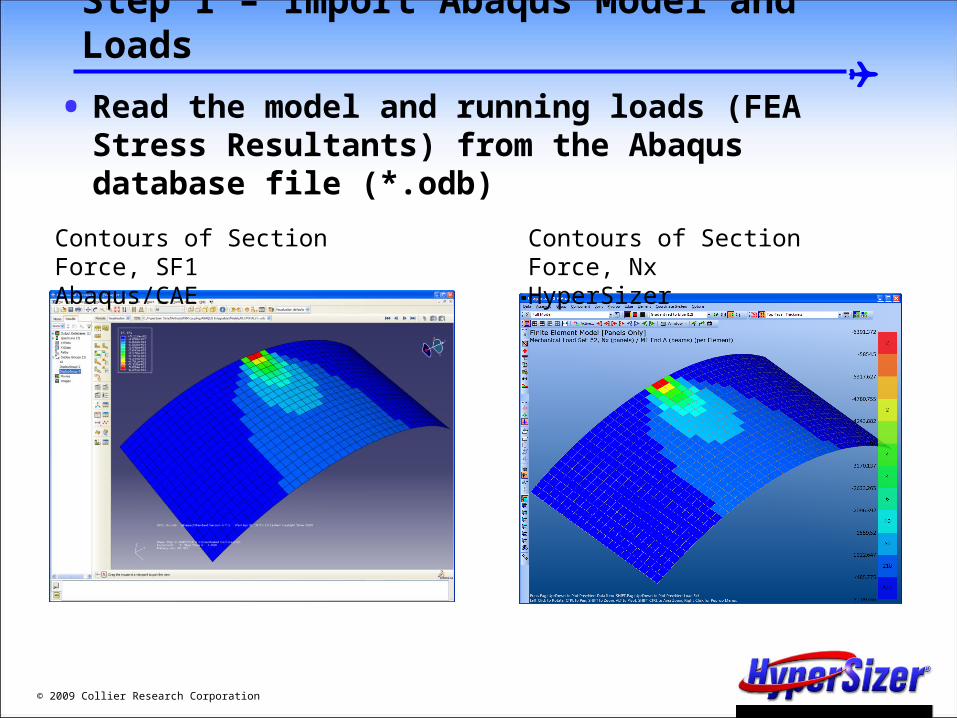
Step 1 – Import Abaqus Model and Loads
• Read the model and running loads (FEA Stress Resultants) from the Abaqus database file (*.odb)
Contours of Section Force, SF1Abaqus/CAE
Contours of Section Force, NxHyperSizer
© 2009 Collier Research Corporation
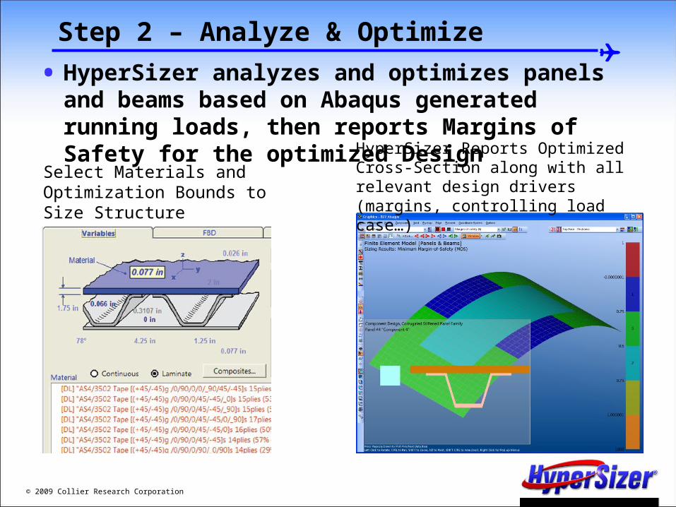
Step 2 – Analyze & Optimize
• HyperSizer analyzes and optimizes panels and beams based on Abaqus generated running loads, then reports Margins of Safety for the optimized Design
Select Materials and Optimization Bounds to Size Structure
HyperSizer Reports Optimized Cross-Section along with all relevant design drivers (margins, controlling load case…)

© 2008 Collier Research Corporation;
Step 2 – Analyze & Optimize
• HyperSizer calculates and report Margins of Safety for every aspect of the stiffened panel, top face, web, crown, etc. as well as margins such as crippling or panel buckling which affect the overall cross-section
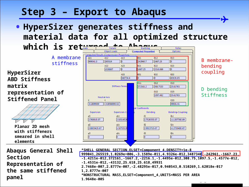
Step 3 – Export to Abaqus
• HyperSizer generates stiffness and material data for all optimized structure which is returned to Abaqus
*SHELL GENERAL SECTION,ELSET=Component_4,DENSITY=1e-8999041,265519,1.0269e+006,-3.1589e-011,4.9326e-012,3487340,-242961,-1667.23,-1.4211e-012,372161,-1667.2,-2216.1,-1.4495e-012,308.75,1097.5,-1.4577e-012,-1.4531e-012,-43132,25.618,25.618,499312.7468e-007,2.8777e-007,-2.48295e-017,0.940543,0.510269,1.62018e-0171,2.8777e-007*NONSTRUCTURAL MASS,ELSET=Component_4,UNITS=MASS PER AREA1.9648e-005
HyperSizer ABD Stiffness matrix representation of Stiffened Panel
Abaqus General Shell Section Representation of the same stiffened panel
A membranestiffness
B membrane-bending coupling
D bending Stiffness
Planar 2D mesh with stiffeners smeared in shell elements
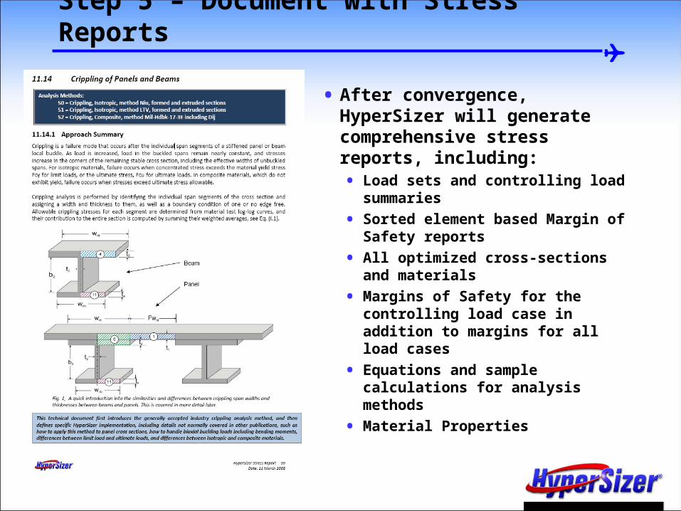
Step 5 – Document with Stress Reports
• After convergence, HyperSizer will generate comprehensive stress reports, including:• Load sets and controlling load
summaries
• Sorted element based Margin of Safety reports
• All optimized cross-sections and materials
• Margins of Safety for the controlling load case in addition to margins for all load cases
• Equations and sample calculations for analysis methods
• Material Properties
Joint Analysis

© 2009 Collier Research Corporation
Project Overview
• you can talk about HyperMAC
• ST into Hs
• Siva stuff into HS
• and joints
• Brett says:
• Maybe the open hole thing too - that is multiscale
• basically, anything embedded that is a local analyss
• Actually, all of Hs is multiscale when running HyperFEA
• how your whole process is based on a global loads model
• and then your efficient local model for the panel segments


![Laplacian Dynamics and Multiscale Modular arXiv:0812.1770v3 … · 2009-10-09 · arXiv:0812.1770v3 [physics.soc-ph] 9 Oct 2009 Laplacian Dynamics and Multiscale Modular Structure](https://img.pdfslide.us/doc/110x75/5e7f491b8c37393dd67d4ce9/laplacian-dynamics-and-multiscale-modular-arxiv08121770v3-2009-10-09-arxiv08121770v3.jpg)