Embed Size (px)
Citation preview


© 2008 Autodesk, Inc. All rights reserved. Except as otherwise permitted by Autodesk, Inc., this publication, or parts thereof, may not be reproducedin any form, by any method, for any purpose.
Certain materials included in this publication are reprinted with the permission of the copyright holder.
Portions relating to ADOdb Copyright © 2000, 2001, 2002, 2003, 2004 John Lim. All rights reserved. Redistribution and use in source and binary forms,with or without modification, are permitted provided that the following conditions are met: Redistributions of source code must retain the above copyrightnotice, this list of conditions and the following disclaimer. Redistributions in binary form must reproduce the above copyright notice, this list of conditionsand the following disclaimer in the documentation and/or other materials provided with the distribution. Neither the name of the John Lim nor the namesof its contributors may be used to endorse or promote products derived from this software without specific prior written permission. DISCLAIMER: THISSOFTWARE IS PROVIDED BY THE COPYRIGHT HOLDERS AND CONTRIBUTORS "AS IS" AND ANY EXPRESS OR IMPLIED WARRANTIES,INCLUDING, BUT NOT LIMITED TO, THE IMPLIED WARRANTIES OF MERCHANTABILITY AND FITNESS FOR A PARTICULAR PURPOSEARE DISCLAIMED. IN NO EVENT SHALL JOHN LIM OR CONTRIBUTORS BE LIABLE FOR ANY DIRECT, INDIRECT, INCIDENTAL, SPECIAL,EXEMPLARY, OR CONSEQUENTIAL DAMAGES (INCLUDING, BUT NOT LIMITED TO, PROCUREMENT OF SUBSTITUTE GOODS ORSERVICES; LOSS OF USE, DATA, OR PROFITS; OR BUSINESS INTERRUPTION HOWEVER CAUSED AND ON ANY THEORY OF LIABILITY,WHETHER IN CONTRACT, STRICT LIABILITY, OR TORT (INCLUDING NEGLIGENCE OR OTHERWISE) ARISING IN ANY WAY OUT OFTHE USE OF THIS SOFTWARE, EVEN IF ADVISED OF THE POSSIBILITY OF SUCH DAMAGE.
Portions relating to GetOpt Copyright © 1987, 1993, 1994. The Regents of the University of California. All rights reserved. Redistribution and use in sourceand binary forms, with or without modification, are permitted provided that the following conditions are met: 1. Redistributions of source code must retainthe above copyright notice, this list of conditions and the following disclaimer. 2. Redistributions in binary form must reproduce the above copyright notice,this list of conditions and the following disclaimer in the documentation and/or other materials provided with the distribution. 3. All advertising materialsmentioning features or use of this software must display the following acknowledgement: This product includes software developed by the University ofCalifornia, Berkeley and its contributors. 4. Neither the name of the University nor the names of its contributors may be used to endorse or promote productsderived from this software without specific prior written permission. THIS SOFTWARE IS PROVIDED BY THE REGENTS AND CONTRIBUTORS "ASIS" AND ANY EXPRESS OR IMPLIED WARRANTIES, INCLUDING, BUT NOT LIMITED TO, THE IMPLIED WARRANTIES OFMERCHANTABILITY AND FITNESS FOR A PARTICULAR PURPOSE ARE DISCLAIMED. IN NO EVENT SHALL THE REGENTS ORCONTRIBUTORS BE LIABLE FOR ANY DIRECT, INDIRECT, INCIDENTAL, SPECIAL, EXEMPLARY, OR CONSEQUENTIAL DAMAGES(INCLUDING, BUT NOT LIMITED TO, PROCUREMENT OF SUBSTITUTE GOODS OR SERVICES; LOSS OF USE, DATA, OR PROFITS; ORBUSINESS INTERRUPTION) HOWEVER CAUSED AND ON ANY THEORY OF LIABILITY, WHETHER IN CONTRACT, STRICT LIABILITY, ORTORT (INCLUDING NEGLIGENCE OR OTHERWISE) ARISING IN ANY WAY OUT OF THE USE OF THIS SOFTWARE, EVEN IF ADVISED OFTHE POSSIBILITY OF SUCH DAMAGE.
Portions relating to GetOpt Copyright ©1999, 2000 Politecnico di Torino. All rights reserved. Redistribution and use in source and binary forms, with orwithout modification, are permitted provided that: (1) source code distributions retain the above copyright notice and this paragraph in its entirety, (2)distributions including binary code include the above copyright notice and this paragraph in its entirety in the documentation or other materials providedwith the distribution, and (3) all advertising materials mentioning features or use of this software display the following acknowledgement:"This productincludes software developed by the Politecnico di Torino, and its contributors." Neither the name of the University nor the names of its contributors may beused to endorse or promote products derived from this software without specific prior written permission. THIS SOFTWARE IS PROVIDED "AS IS" ANDWITHOUT ANY EXPRESS OR IMPLIED WARRANTIES, INCLUDING, WITHOUT LIMITATION, THE IMPLIED WARRANTIES OFMERCHANTABILITY AND FITNESS FOR A PARTICULAR PURPOSE.
Portions relating to LibXML2 2.6.20 Copyright © 2005 Daniel Veillard. Permission is hereby granted, free of charge, to any person obtaining a copy of thissoftware and associated documentation files (the "Software"), to deal in the Software without restriction, including without limitation the rights to use,copy, modify, merge, publish, distribute, sublicense, and/or sell copies of the Software, and to permit persons to whom the Software is furnished to do so,subject to the following conditions: The above copyright notice and this permission notice shall be included in all copies or substantial portions of theSoftware. THE SOFTWARE IS PROVIDED "AS IS", WITHOUT WARRANTY OF ANY KIND, EXPRESS OR IMPLIED, INCLUDING BUT NOTLIMITED TO THE WARRANTIES OF MERCHANTABILITY, FITNESS FOR A PARTICULAR PURPOSE AND NONINFRINGEMENT. IN NOEVENT SHALL THE AUTHORS OR COPYRIGHT HOLDERS BE LIABLE FOR ANY CLAIM, DAMAGES OR OTHER LIABILITY, WHETHER INAN ACTION OF CONTRACT, TORT OR OTHERWISE, ARISING FROM, OUT OF OR IN CONNECTION WITH THE SOFTWARE OR THE USEOR OTHER DEALINGS IN THE SOFTWARE.
The following are registered trademarks or trademarks of Autodesk, Inc., in the USA and other countries: 3DEC (design/logo), 3December,3December.com, 3ds Max, ADI, Alias, Alias (swirl design/logo), AliasStudio, Alias|Wavefront (design/logo), ATC, AUGI, AutoCAD, AutoCAD LearningAssistance, AutoCAD LT, AutoCAD Simulator, AutoCAD SQL Extension, AutoCAD SQL Interface, Autodesk, Autodesk Envision, Autodesk Insight,Autodesk Intent, Autodesk Inventor, Autodesk Map, Autodesk MapGuide, Autodesk Streamline, AutoLISP, AutoSnap, AutoSketch, AutoTrack, Backdraft,Built with ObjectARX (logo), Burn, Buzzsaw, CAiCE, Can You Imagine, Character Studio, Cinestream, Civil 3D, Cleaner, Cleaner Central, ClearScale,Colour Warper, Combustion, Communication Specification, Constructware, Content Explorer, Create>what's>Next> (design/logo), Dancing Baby(image), DesignCenter, Design Doctor, Designer's Toolkit, DesignKids, DesignProf, DesignServer, DesignStudio, Design|Studio (design/logo), DesignWeb Format, DWF, DWG, DWG (logo), DWG Extreme, DWG TrueConvert, DWG TrueView, DXF, Ecotect, Exposure, Extending the Design Team, FBX,Filmbox, FMDesktop, Freewheel, GDX Driver, Gmax, Green Building Studio, Heads-up Design, Heidi, HumanIK, IDEA Server, i-drop, ImageModeler,iMOUT, Incinerator, Inventor, Inventor LT, Kaydara, Kaydara (design/logo), Kynapse, Kynogon, LocationLogic, Lustre, Matchmover, Maya, MechanicalDesktop, MotionBuilder, Movimento, Mudbox, NavisWorks, ObjectARX, ObjectDBX, Open Reality, Opticore, Opticore Opus, PolarSnap, PortfolioWall,Powered with Autodesk Technology, Productstream, ProjectPoint, ProMaterials, RasterDWG, Reactor, RealDWG, Real-time Roto, REALVIZ, Recognize,Render Queue, Retimer,Reveal, Revit, Showcase, ShowMotion, SketchBook, SteeringWheels, Stitcher, StudioTools, Topobase, Toxik, TrustedDWG,ViewCube, Visual, Visual Construction, Visual Drainage, Visual Landscape, Visual Survey, Visual Toolbox, Visual LISP, Voice Reality, Volo, Vtour, Wiretap,and WiretapCentral.

The following are registered trademarks or trademarks of Autodesk Canada Co. in the USA and/or Canada and other countries: Backburner,Discreet, Fire, Flame, Flint, Frost, Inferno, Multi-Master Editing, River, Smoke, Sparks, Stone, and Wire.
The following are registered trademarks or trademarks of Moldflow Corp. in the USA and/or other countries: Moldflow MPA, MPA (design/logo),Moldflow Plastics Advisers, MPI, MPI (design/logo), Moldflow Plastics Insight, MPX, MPX (design/logo), Moldflow Plastics Xpert.
All other brand names, product names or trademarks belong to their respective holders.
DisclaimerTHIS PUBLICATION AND THE INFORMATION CONTAINED HEREIN IS MADE AVAILABLE BY AUTODESK, INC. "AS IS." AUTODESK,INC. DISCLAIMS ALL WARRANTIES, EITHER EXPRESS OR IMPLIED, INCLUDING BUT NOT LIMITED TO ANY IMPLIEDWARRANTIES OF MERCHANTABILITY OR FITNESS FOR A PARTICULAR PURPOSE REGARDING THESE MATERIALS.
Title: Autodesk Lustre 2009 Software Installation Guide for Linux Workstations
Document Version: 1
Date: October 10, 2008


contents
v
Contents
1 Introduction 1Summary . . . . . . . . . . . . . . . . . . . . . . . . . . . . . . . . . . . . . . . . . . . . . . . . . . . . . . . . . . . . . . . 1About This Guide . . . . . . . . . . . . . . . . . . . . . . . . . . . . . . . . . . . . . . . . . . . . . . . . . . . . . . . . 1Related Documentation. . . . . . . . . . . . . . . . . . . . . . . . . . . . . . . . . . . . . . . . . . . . . . . . . . . 1
Accessing PDF Documentation . . . . . . . . . . . . . . . . . . . . . . . . . . . . . . . . . . . . . . . 2Notational Conventions . . . . . . . . . . . . . . . . . . . . . . . . . . . . . . . . . . . . . . . . . . . . . . . . . . 3Contacting Customer Support . . . . . . . . . . . . . . . . . . . . . . . . . . . . . . . . . . . . . . . . . . . . . 4Lustre Hardware and Software Components . . . . . . . . . . . . . . . . . . . . . . . . . . . . . . . . . 4
Lustre Workstations . . . . . . . . . . . . . . . . . . . . . . . . . . . . . . . . . . . . . . . . . . . . . . . . . 4Other Components . . . . . . . . . . . . . . . . . . . . . . . . . . . . . . . . . . . . . . . . . . . . . . . . . . 5
Typical Workgroup Configuration . . . . . . . . . . . . . . . . . . . . . . . . . . . . . . . . . . . . . . . . . 6
2 Configuring Storage 9Summary . . . . . . . . . . . . . . . . . . . . . . . . . . . . . . . . . . . . . . . . . . . . . . . . . . . . . . . . . . . . . . . 9Workflow for Configuring Storage . . . . . . . . . . . . . . . . . . . . . . . . . . . . . . . . . . . . . . . . . 9Connecting and Powering Up Storage . . . . . . . . . . . . . . . . . . . . . . . . . . . . . . . . . . . . . . 10Creating Hardware LUNs . . . . . . . . . . . . . . . . . . . . . . . . . . . . . . . . . . . . . . . . . . . . . . . . . 10LUNs and Partitions. . . . . . . . . . . . . . . . . . . . . . . . . . . . . . . . . . . . . . . . . . . . . . . . . . . . . . 11
Creating the Partition Type on the LUNs . . . . . . . . . . . . . . . . . . . . . . . . . . . . . . . 11Checking Storage Device Detection . . . . . . . . . . . . . . . . . . . . . . . . . . . . . . . . . . . . 13Checking Storage Device Partitions . . . . . . . . . . . . . . . . . . . . . . . . . . . . . . . . . . . . 14
Assembling the LUNs into a Logical Volume . . . . . . . . . . . . . . . . . . . . . . . . . . . . . . . . 15Creating the XFS Filesystem on the Storage Array . . . . . . . . . . . . . . . . . . . . . . . . . . . . 18

tentsCon
vi
3 Installing Lustre on the Linux Workstation 21Summary . . . . . . . . . . . . . . . . . . . . . . . . . . . . . . . . . . . . . . . . . . . . . . . . . . . . . . . . . . . . . . . 21Overview. . . . . . . . . . . . . . . . . . . . . . . . . . . . . . . . . . . . . . . . . . . . . . . . . . . . . . . . . . . . . . . . 21Installation Requirements Checklist . . . . . . . . . . . . . . . . . . . . . . . . . . . . . . . . . . . . . . . . 21Determining the Red Hat Enterprise Linux Version . . . . . . . . . . . . . . . . . . . . . . . . . . 22Determining the Kernel Version . . . . . . . . . . . . . . . . . . . . . . . . . . . . . . . . . . . . . . . . . . . 22Mounting an CD-ROM Drive. . . . . . . . . . . . . . . . . . . . . . . . . . . . . . . . . . . . . . . . . . . . . . 23Installing Lustre. . . . . . . . . . . . . . . . . . . . . . . . . . . . . . . . . . . . . . . . . . . . . . . . . . . . . . . . . . 23Acquiring and Installing a License . . . . . . . . . . . . . . . . . . . . . . . . . . . . . . . . . . . . . . . . . . 24
Determining the License Codes You Require . . . . . . . . . . . . . . . . . . . . . . . . . . . 24Obtaining the lmhostid of the Workstation . . . . . . . . . . . . . . . . . . . . . . . . . . . . . 25Requesting License Codes . . . . . . . . . . . . . . . . . . . . . . . . . . . . . . . . . . . . . . . . . . . 25Installing License Codes . . . . . . . . . . . . . . . . . . . . . . . . . . . . . . . . . . . . . . . . . . . . . . 26
Starting the Software for the First Time . . . . . . . . . . . . . . . . . . . . . . . . . . . . . . . . . . . . . 27
4 Configuring Slave Rendering 29Summary . . . . . . . . . . . . . . . . . . . . . . . . . . . . . . . . . . . . . . . . . . . . . . . . . . . . . . . . . . . . . . . 29Workflow for Configuring Slave Rendering. . . . . . . . . . . . . . . . . . . . . . . . . . . . . . . . . . 29Configuring the Network Addresses . . . . . . . . . . . . . . . . . . . . . . . . . . . . . . . . . . . . . . . . 30Installing the Slave Renderer Software and License . . . . . . . . . . . . . . . . . . . . . . . . . . . 31Configuring Read/Write Access to Storage from the Slave Renderer . . . . . . . . . . . . 32Mounting the Storage on the Slave Renderer. . . . . . . . . . . . . . . . . . . . . . . . . . . . . . . . . 33Setting Up Lustre Projects to Use Slave Rendering . . . . . . . . . . . . . . . . . . . . . . . . . . . . 34
5 Configuring Background Rendering 35Summary . . . . . . . . . . . . . . . . . . . . . . . . . . . . . . . . . . . . . . . . . . . . . . . . . . . . . . . . . . . . . . . 35About Background Rendering . . . . . . . . . . . . . . . . . . . . . . . . . . . . . . . . . . . . . . . . . . . . . 35
Background Rendering Related Documentation . . . . . . . . . . . . . . . . . . . . . . . . 35Background Rendering Components . . . . . . . . . . . . . . . . . . . . . . . . . . . . . . . . . . . . . . . 36Workflow for Setting Up Background Rendering. . . . . . . . . . . . . . . . . . . . . . . . . . . . . 37Sharing the Storage for Read/Write Access from Background Render Nodes . . . . . 38Installing Backburner Manager and Backburner Monitor . . . . . . . . . . . . . . . . . . . . . 39Configuring Lustre to Detect Backburner Manager . . . . . . . . . . . . . . . . . . . . . . . . . . . 40Setting Up Render Nodes . . . . . . . . . . . . . . . . . . . . . . . . . . . . . . . . . . . . . . . . . . . . . . . . . 40
Render Node Hardware and Software Requirements . . . . . . . . . . . . . . . . . . . . . 41Mounting the Storage on the Render Nodes . . . . . . . . . . . . . . . . . . . . . . . . . . . . 41Installing and Configuring Burn for Lustre . . . . . . . . . . . . . . . . . . . . . . . . . . . . . 43
Specifying the Background Rendering Path in Lustre . . . . . . . . . . . . . . . . . . . . . . . . . 48

Contents
vii
6 Configuring BrowseD 49Summary . . . . . . . . . . . . . . . . . . . . . . . . . . . . . . . . . . . . . . . . . . . . . . . . . . . . . . . . . . . . . . . 49About BrowseD . . . . . . . . . . . . . . . . . . . . . . . . . . . . . . . . . . . . . . . . . . . . . . . . . . . . . . . . . . 49Workflow for Configuring BrowseD . . . . . . . . . . . . . . . . . . . . . . . . . . . . . . . . . . . . . . . . 50Starting and Stopping the BrowseD Service . . . . . . . . . . . . . . . . . . . . . . . . . . . . . . . . . . 50Configuring Workstations to Use the BrowseD Server . . . . . . . . . . . . . . . . . . . . . . . . 50Making BrowseD Directories Accessible from the Lustre Browser . . . . . . . . . . . . . . 51Using BrowseD for Rendering with Burn for Lustre. . . . . . . . . . . . . . . . . . . . . . . . . . . 52
A Software, Project, and User Configuration Files55Summary . . . . . . . . . . . . . . . . . . . . . . . . . . . . . . . . . . . . . . . . . . . . . . . . . . . . . . . . . . . . . . . 55Configuration File Overview. . . . . . . . . . . . . . . . . . . . . . . . . . . . . . . . . . . . . . . . . . . . . . . 55System Settings . . . . . . . . . . . . . . . . . . . . . . . . . . . . . . . . . . . . . . . . . . . . . . . . . . . . . . . . . . 56
Index 61

tentsCon
viii
1
Introduction
SummaryAbout This Guide . . . . . . . . . . . . . . . . . . . . . . . . . . . . . . . . . . . . . . . . . . . . . . . . . . . . . . . . . 1
Related Documentation . . . . . . . . . . . . . . . . . . . . . . . . . . . . . . . . . . . . . . . . . . . . . . . . . . . 1
Notational Conventions . . . . . . . . . . . . . . . . . . . . . . . . . . . . . . . . . . . . . . . . . . . . . . . . . . . 3
Contacting Customer Support . . . . . . . . . . . . . . . . . . . . . . . . . . . . . . . . . . . . . . . . . . . . . 4
Lustre Hardware and Software Components . . . . . . . . . . . . . . . . . . . . . . . . . . . . . . . 4
Typical Workgroup Configuration . . . . . . . . . . . . . . . . . . . . . . . . . . . . . . . . . . . . . . . . . 6
About This GuideThis guide provides basic information about installing Autodesk® Lustre® 2009 application software on the hardware components in your Lustre system. Use this guide in conjunction with the Hardware Setup Guide for your platform to install and configure the hardware and software components of your Lustre system.
The most up-to-date versions of all guides are available in PDF format from the Web at www.autodesk.com/lustre-documentation. For the best results viewing and printing these PDF files, use Adobe® Acrobat® Reader™ 6 or later.
NOTE: In most cases, both hardware setup and application installation is done on delivery by an
authorized technician, so you may not need to perform all of the procedures in these guides.
Related DocumentationThe following table describes the documentation associated with your application. For a detailed list of the latest documentation, see your release notes.
User Guides Provides
Autodesk Lustre 2009 User Guide Detailed instructions on using the software.
Autodesk Control Surface User Guide Detailed instructions on using the Autodesk control surface and the Tangent CP100.

Introduction1
2
Consult the Autodesk Web site at www.autodesk.com/lustre-documentation for the latest version of guides, release notes, and fixed and known bugs documents.
Accessing PDF DocumentationThe complete documentation set is available in PDF (Portable Document Format) for online viewing and printing. On Windows® systems, use Adobe® Acrobat® Reader™ to view and print the PDF files. On Linux® workstations, use either Adobe Acrobat Reader or the Xpdf viewer. You can access the PDF files from the Lustre software CD or from www.autodesk.com/lustre-documentation.
NOTE: If you do not have Acrobat Reader, you can download a free copy from the Adobe Web site
(www.adobe.com). If you do not have Xpdf viewer, you can download a free copy from the Xpdf
Web site (www.foolabs.com/xpdf/).
Autodesk Lustre 2009 New Features Guide Information about the new features for this release.
Autodesk Lustre 2009 Hot Keys Card A list of the most frequently used hot keys.
Autodesk Lustre 2009 Release Notes A complete list of documentation and information on late-breaking features.
Autodesk Lustre 2009 Fixed and Known Bug List
A complete list of fixed and known bugs for this release.
Installation and Configuration Guides Provides
Hardware Setup Guide (for your workstation)
Information on how to set up your workstation and video I/O peripherals.
Stone Direct Configuration Guide Detailed connectivity diagrams and configuration procedures for your Autodesk Stone® storage arrays.
Stone and Wire Filesystem and Networking Guide
Procedures for configuring your Autodesk Wiretap® services.
Autodesk Lustre 2009 Software Installation Guide (for your operating system)
Information about installing and licensing yourAutodesk Lustre software.
Autodesk Incinerator 2009 Installation and User Guide
Information on installing, licensing, and using Autodesk® Incinerator®.
Other Guides Provides
Autodesk Lustre Sparks API Reference Guide
Instructions for developing Sparks® plugins for Lustre.
Autodesk Backburner 2008.1 Installation Guide
Information on how to install and set up Autodesk Backburner™.
Autodesk Backburner 2008.1 User Guide Information on how to use Autodesk Backburner.
User Guides Provides

Notational Conventions
3
From the Lustre Application CDYou can view and print the PDF files from the Lustre CD using Adobe Acrobat Reader. PDF files are located in a directory called Documentation at the top level of the CD.
To view the PDF files on the application CD:
1. Place the Lustre CD in the CD-ROM drive of your system.
2. If using the Windows version of Lustre, in Windows Explorer, go to the Documentation folder on the CD.
3. If using the Linux version of Lustre, open a Linux shell and navigate to the Documentation folder on the CD. Type:
/mnt/cdrom/documentation
4. To view one of the documentation PDF files, do one of the following:
• If using the Windows version of Lustre, double-click the desired file.
• If using the Linux version of Lustre, type:
xpdf <filename>
The file opens in Acrobat Reader or the Xpdf viewer.
Accessing PDF Documentation from the Autodesk Web SiteYou can also find the PDF files on the Autodesk Web site, www.autodesk.com/lustre-documentation, and download any of the available files.
Notational ConventionsA number of style conventions are used throughout this guide. These conventions and examples of their use are shown as follows.
Convention Example
Text that you enter in a command line or shell appears in Courier bold. You must press the Enter key after each command.
rpm -qa
Variable names appear in Courier, enclosed in angle brackets.
<filename>
Feedback from the command line or shell appears in Courier.
limit coredumpsize
Directory names, filenames, URLs, and command line utilities appear in italics.
/usr/autodesk

Introduction1
4
NOTE: Throughout this guide, when referring to Windows-specific file locations, the term folder
will be used. When referring to Linux-specific file locations, the term directory will be used. When
referring to both, directory will be used.
Contacting Customer SupportA list of contact information for Autodesk Media and Entertainment Customer Support is available at www.autodesk.com/support.
Customer support is also available through your Autodesk reseller. To find a reseller near you, consult the reseller look-up database on the Autodesk Web site at www.autodesk.com/resellers.
Lustre Hardware and Software ComponentsA Lustre system consists of a number of different hardware and software components. This section describes each of the hardware components in a Lustre installation, and the software associated with each component. You may or may not have all of the components listed here in your Lustre installation. The type of workgroup, as well as the feature set you purchase for each of the workstations in that workgroup, determine the components in your installation.
Lustre WorkstationsThere are three kinds of Lustre workstations: the Master Station, the HD Station, and the Lustre Station. Every Lustre installation is built around either a Master Station or an HD Station. The optional Lustre Station offers a way to improve the efficiency and cost-effectiveness of a pipeline by offloading tasks that do not require the full feature set of the Master Station or HD Station.
Master StationThe Master Station is designed for GPU-accelerated sessions where the colorist works together with the cinematographer. It includes an extensive creative toolset for elaborate visual design and grading, using up to 4K resolution and 16-bit files and for completing tasks like dust busting, conforming, rotoscoping, and capture/playout. It also includes SD and HD I/O, dual link and HSDL video formats, and the DI Pack, which consists of infrared channel dust removal and support for all standard input and output resolutions and bit-depths.
The Master Station can support up to three panels of the Autodesk Control Surface and, with an additional license, a Slave Renderer. You can also purchase licenses for plug-ins.
You install the Lustre application on the Master Station.

Lustre Hardware and Software Components
5
HD StationThe HD Station is a cost-effective GPU workstation for conforming, preparing, grading, and mastering short-form and long-form HDTV projects, as well as HD film projects, and mastering to different formats. It does not include the DI Pack. File input is limited to 10-bit 2K resolution, and file output is limited to SD and 10-bit HD resolution.
The HD Station can support up to three panels of the Autodesk Control Surface and, with an additional license, a Slave Renderer. Dual link and HSDL video formats are available with the purchase of a separate video I/O license. You can also purchase licenses for plug-ins.
You install the Lustre application on the HD Station.
Lustre StationTasks that do not require the direct intervention or supervision of the colorist can be efficiently handled by a Lustre Station. Multiple Lustre Stations can work in parallel to increase throughput and can be used for tasks such as dust-busting, preparatory work, fine-tuning creative sessions, conforming data from EDLs, updating editorial changes, and mastering to different formats using the real-time deliverables function. The Lustre Station includes the DI Pack, along with full dust removal functionality, and the ability to create geometries and masks.
Primary colour grading on the Lustre Station requires a separate license. The following features also require an additional license: SD and HD I/O, dual link and HSDL video formats, and plug-ins.
The Lustre Station does not support the Slave Renderer.
You install the Lustre application on the Lustre Station.
Other ComponentsYou can expand the features of your Lustre system and improve the efficiency of your workflow by adding any of the following components.
Control Surface — The Autodesk Control Surface provides improved interactivity when colour grading film and video footage. You can perform many of the same tasks you do in the Lustre user interface using the Control Surface.
You connect the Autodesk Control Surface to a Master Station or HD Station, and configure the Control Surface on the workstation to which it is connected.
Video I/O Board and Breakout Box — On the HP 8600, video I/O is provided by the AJA board, while other workstations use the DVS Centaurus board. Both video boards consist of an HD/SD board and a breakout box. This configuration provides real-time SDI input and output of uncompressed 8- or 10-bit HD or SD video in both YUV (4:2:2) and RGB formats (4:4:4 or 4:2:2). For a list of supported video formats, see the Lustre 2009 User Guide.

Introduction1
6
The drivers for the video board and breakout box are installed by the Discreet® Kernel Utility, as part of the Red Hat® Linux installation procedure.
Slave Renderer — The Slave Renderer is a rack-mounted server that is connected directly to the Lustre workstation. It frees system resources by off-loading render tasks, thus ensuring real-time interaction on the Lustre system.
You install rendering software on the Slave Renderer.
Background Renderer — Background rendering frees up Lustre workstations for colour grading. You can use up to eight background rendering machines to process your final frames.
You install background rendering software on each background render node.
Typical Workgroup ConfigurationThe following illustration shows a typical workgroup configuration built around a Master Station. It includes a Lustre Station, and other optional components.

Typical Workgroup Configuration
7
NOTE: Although not illustrated, you can expand your system to include a Visual Effects and
Finishing workstation. If you do so, you must install and configure BrowseD and Autodesk
Wiretap® on that workstation to enable Lustre read/write access to the storage connected to the
Visual Effects and Finishing workstation. This feature assumes that the Visual Effects and Finishing
workstation is on the same network (GigE or Infiniband) as the Incinerator® workgroup, and that
the “Scans/Render Full Home” project variable is properly configured in Lustre.
SAN optionsLustre Station
Control Surface
Video I/O (DVS Centaurus + Break out box)
Slave Renderer
RS422A
RS422BGPICVBSWclkAudio InLTC
1/2In OutOutOut
3/4 5/6 7/8 1/2 3/4 5/6 7/8
Out
Video I/O
RS422A
RS422BGPICVBSWclkAudio InLTC
1/2In OutOutOut
3/4 5/6 7/8 1/2 3/4 5/6 7/8
Out
Background Rendering (burn)
Lustre Master Workstation
Lustre Storage
Peripheral Options
Network Options
Stone Shared
HighHue Brightness Saturation
G+ B+R+
R G B Sh MidBrightBright
+G - B -R - -
Multi
MatteO/P
StillALT
WipeSplit
Proxy
.
Curve KeyP&S
InsideMisc
Outside#0001.000019
InPr OutPr
Geom
Grade
GRADE CURVES KEY GEOM P&S MISCMORE
MOREOUT
IN
1
+/-
4
7
5 6
98
2
0
3
ALT
ENTER
CURSOR REVERT COMP
UNDOREDO
DO
RECALL OFFSET GRADE
CLIPA/B
CUE
F1 F2F3 F4 F5
F6
F7 F8F9
ShadowContrast
Brightness

Introduction1
8

9
Configuring Storage
SummaryWorkflow for Configuring Storage . . . . . . . . . . . . . . . . . . . . . . . . . . . . . . . . . . . . . . . . . 9
Connecting and Powering Up Storage . . . . . . . . . . . . . . . . . . . . . . . . . . . . . . . . . . . . 10
Creating Hardware LUNs . . . . . . . . . . . . . . . . . . . . . . . . . . . . . . . . . . . . . . . . . . . . . . . . . 10
LUNs and Partitions . . . . . . . . . . . . . . . . . . . . . . . . . . . . . . . . . . . . . . . . . . . . . . . . . . . . . . 11
Assembling the LUNs into a Logical Volume . . . . . . . . . . . . . . . . . . . . . . . . . . . . . . . 15
Creating the XFS Filesystem on the Storage Array . . . . . . . . . . . . . . . . . . . . . . . . . . 18
Workflow for Configuring StorageYou must connect some storage to the Lustre workstation. After the storage is connected, it must be configured to provide access to all frames and proxies.
NOTE: This chapter describes how to configure a direct-attached storage. If you are also
configuring a Storage Area Network (SAN), it is recommended that you configure the SAN prior to
configuring a direct-attached storage.
Before you can configure the storage, the Lustre workstation must be up, and running a custom distribution of 64-bit Red Hat Linux supplied by Autodesk, which includes a custom kernel, drivers, and other required utilities. If necessary, refer to the Linux RHEW 4 Update 3 Installation and Configuration Guidefor help installing Linux on the Lustre workstation.
NOTE: For a list of storage configurations supported by your system, refer to the Storage vs Systems
Matrix. If your storage configuration is an earlier generation than those listed in the Storage vs
Systems Matrix, refer to the Stone Direct Configuration Guide.
See the following table for the recommended steps for configuring Lustre storage.

Configuring Storage2
10
Connecting and Powering Up Storage You must connect the Lustre workstation to the storage. Refer to the latest edition of the Autodesk Stone Direct Configuration Guide for illustrations demonstrating how to connect storage to your system.
To connect and power up the storage:
1. Power down the workstation.
2. Use the optical cabling provided to connect the fiber channel adapter ports on the workstation to the appropriate ports on the storage arrays, as illustrated in the Autodesk Stone Direct Configuration Guide.
3. Power up the storage arrays.
4. Power up the workstation.
Creating Hardware LUNsPhysical disks in storage devices are grouped into Logical Units (LUNs). The operating system sees each LUN as a single disk, even though each LUN is composed of several physical disks.
Refer to the latest edition of the Autodesk Stone Direct Configuration Guide for help creating LUNs on both IR-series and XR-series storage.
NOTE: LUN configurations are designed and tested by Autodesk to provide optimal performance
for media playback on your workstation. Although the RAID management utilities (Stone Storage
Step: Refer to:
1. Connect and power-up the storage devices. “Connecting and Powering Up Storage” on page 10.
2. Create the hardware LUNs (Logical UNits). “Creating Hardware LUNs” on page 10.
3. Configure the LUNs on the storage devices as Linux LVM partitions and verify that they are detected by the operating system.
“LUNs and Partitions” on page 11.
4. Assemble all of the LUNs into a single logical volume. When assembled, all LUNs appear as one device to the operating system.
“Assembling the LUNs into a Logical Volume” on page 15.
5. Create and mount the XFS filesystem on the storage array.
“Creating the XFS Filesystem on the Storage Array” on page 18.
WARNING: You must power down the workstation before you connect the storage.

LUNs and Partitions
11
Manager for XR-series storage, and Discreet Storage Manager for IR-series storage) let you
customize LUN configuration manually, deviating from the documented LUN configuration
procedures is not supported.
LUNs and PartitionsVerify that the LUNs are set up properly before you assemble them into a single logical volume and create the filesystem.
To partition the LUNs and ensure they are detected correctly:
1. Create the partition type on the LUNs. See “Creating the Partition Type on the LUNs” on page 11.
2. Check that all LUNs of the storage devices are detected by the operating system. See “Checking Storage Device Detection” on page 13.
3. Check that each LUN is partitioned as a Linux LVM partition. See “Checking Storage Device Partitions” on page 14.
Creating the Partition Type on the LUNsUse the following procedure to change the partition type of a LUN.
Before you check the number of LUNs detected by the operating system, ensure that:
• All storage devices are connected to the workstation and are powered up.
• The workstation is running.
• You have root access to the workstation.
To clear and recreate the partition type for a LUN:
1. Log in as root to the workstation.
2. Reload the drivers for the fibre channel card. Do one of the following in a shell:
• If your system uses a QLogic fibre channel card (IBM® systems), type:
rmmod qla2300
modprobe -v qla2300
• If your system uses an ATTO fibre channel card (HP systems), type:
rmmod celerityfc
modprobe -v celerityfc
The fibre channel drivers reload and probe the attached storage devices.

Configuring Storage2
12
3. Determine the device names of the LUNs with incorrect partition types. In a shell, type:
fdisk -l | grep dev
4. Note down the device names of the LUNs with incorrect partition types.
5. Clear the unsupported partition type on one of the LUNs using the dd command.
Type:
dd if=/dev/zero of=<disk_name> count=1
where <disk_name> is the full name of a disk you noted down in the previous step. For example, if the disk is named /dev/sdb, the command to clear the partition is:
dd if=/dev/zero of=/dev/sdb count=1
Typically device names start at /dev/sdb. For example, the following table lists typical device names in a six LUN configuration.
The existing partition on the LUN is cleared. You are ready to create a new partition on the LUN using the fdisk utility.
6. Start the fdisk utility for the LUN. Type:
fdisk <disk name>
where <disk name> is the full name of the disk cleared in step 2, such as /dev/sdb.
The fdisk utility starts, checks the LUN, and then displays its prompt.
NOTE: When fdisk starts, a warning about the number of disk cylinders may appear. You can
disregard this warning.
7. At the prompt, press N to display the partition creation menu.
The fdisk utility displays the type of partitions you can create (primary or extended) on the LUN.
WARNING: Do not run the dd command on /dev/sda, the system disk. Doing so may erase the
partition table on that disk, making it impossible for you to reboot the machine. It may also
erase data.
LUN Disk Name
1 /dev/sdb
2 /dev/sdc
3 /dev/sdd
4 /dev/sde
5 /dev/sdf
6 /dev/sdg
LUNs and Partitions
13
8. Create a primary partition on the LUN by typing p at the prompt.
9. When prompted to enter a partition number, type 1 to make the primary partition the first one on the LUN.
10. When prompted to set the starting cylinder number, press ENTER to accept the default.
11. When prompted to set the ending cylinder number, press ENTER to accept the default.
The fdisk prompt reappears. Next, set the type of partition to be created.
12. At the prompt, type t to set the partition type.
You are prompted to enter the hexidecimal code of the partition type to be created on the LUN.
13. Create a Linux LVM partition by typing 8e at the prompt.
The fdisk utility sets the partition to be compatible with a RAID configuration and the following output appears:
Changed system type of partition 1 to 8e (Linux LVM)
Only partitions set up for a Linux LVM configuration are supported on storage devices for Lustre.
14. Save the new partition table by pressing W at the prompt.
15. Repeat steps 4 through 13 for each of the LUNs with an incorrect partition type.
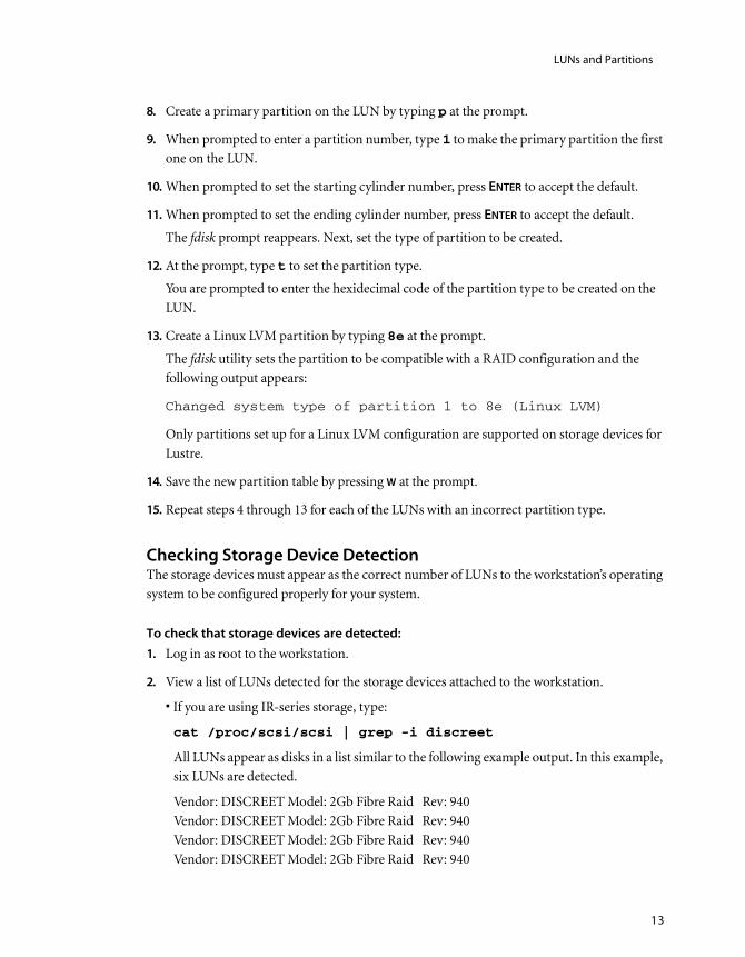
Checking Storage Device DetectionThe storage devices must appear as the correct number of LUNs to the workstation’s operating system to be configured properly for your system.
To check that storage devices are detected:
1. Log in as root to the workstation.
2. View a list of LUNs detected for the storage devices attached to the workstation.
• If you are using IR-series storage, type:
cat /proc/scsi/scsi | grep -i discreet
All LUNs appear as disks in a list similar to the following example output. In this example, six LUNs are detected.
Vendor: DISCREET Model: 2Gb Fibre Raid Rev: 940Vendor: DISCREET Model: 2Gb Fibre Raid Rev: 940Vendor: DISCREET Model: 2Gb Fibre Raid Rev: 940Vendor: DISCREET Model: 2Gb Fibre Raid Rev: 940
Configuring Storage2
14
Vendor: DISCREET Model: 2Gb Fibre Raid Rev: 940Vendor: DISCREET Model: 2Gb Fibre Raid Rev: 940
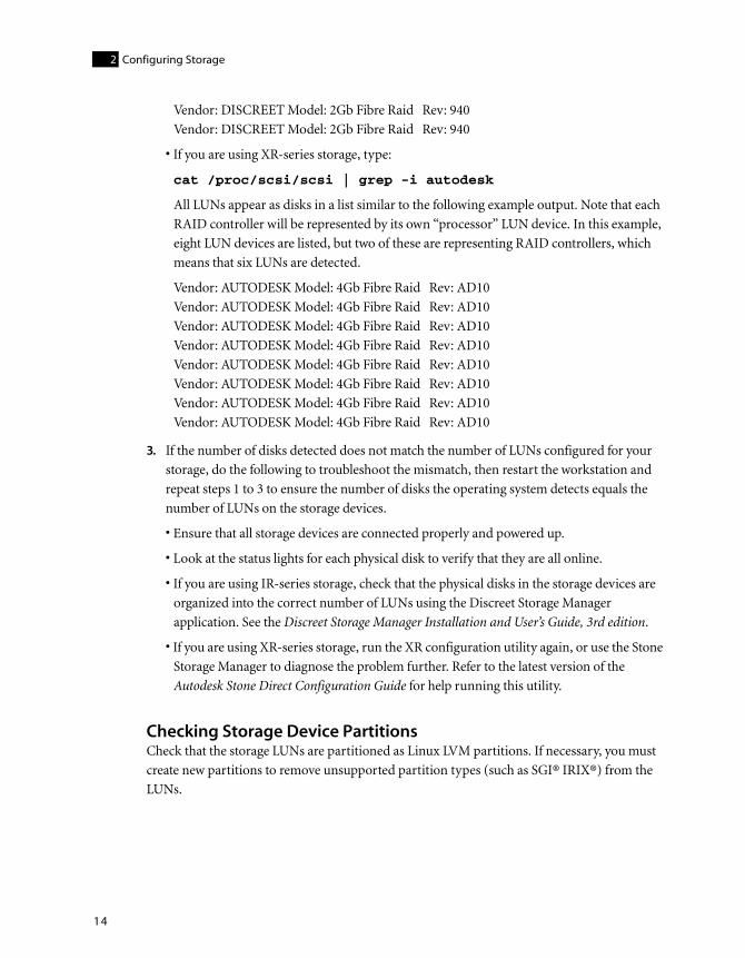
• If you are using XR-series storage, type:
cat /proc/scsi/scsi | grep -i autodesk
All LUNs appear as disks in a list similar to the following example output. Note that each RAID controller will be represented by its own “processor” LUN device. In this example, eight LUN devices are listed, but two of these are representing RAID controllers, which means that six LUNs are detected.
Vendor: AUTODESK Model: 4Gb Fibre Raid Rev: AD10Vendor: AUTODESK Model: 4Gb Fibre Raid Rev: AD10Vendor: AUTODESK Model: 4Gb Fibre Raid Rev: AD10Vendor: AUTODESK Model: 4Gb Fibre Raid Rev: AD10Vendor: AUTODESK Model: 4Gb Fibre Raid Rev: AD10Vendor: AUTODESK Model: 4Gb Fibre Raid Rev: AD10Vendor: AUTODESK Model: 4Gb Fibre Raid Rev: AD10Vendor: AUTODESK Model: 4Gb Fibre Raid Rev: AD10
3. If the number of disks detected does not match the number of LUNs configured for your storage, do the following to troubleshoot the mismatch, then restart the workstation and repeat steps 1 to 3 to ensure the number of disks the operating system detects equals the number of LUNs on the storage devices.
• Ensure that all storage devices are connected properly and powered up.
• Look at the status lights for each physical disk to verify that they are all online.
• If you are using IR-series storage, check that the physical disks in the storage devices are organized into the correct number of LUNs using the Discreet Storage Manager application. See the Discreet Storage Manager Installation and User’s Guide, 3rd edition.
• If you are using XR-series storage, run the XR configuration utility again, or use the Stone Storage Manager to diagnose the problem further. Refer to the latest version of the Autodesk Stone Direct Configuration Guide for help running this utility.
Checking Storage Device PartitionsCheck that the storage LUNs are partitioned as Linux LVM partitions. If necessary, you must create new partitions to remove unsupported partition types (such as SGI® IRIX®) from the LUNs.

Assembling the LUNs into a Logical Volume
15
To check storage device partitions:
1. Log in as root to the workstation.
2. View a list of LUNs for the storage devices attached to the workstation to confirm that they are “Linux lvm” partitions. In a shell, type:
fdisk -l | grep dev
All LUNs appear as disks in a list similar to the following example. The example is for an eight LUN storage configuration.
Disk /dev/sdb: 726.2 GB, 726247931904 bytes
/dev/sdb1 1 88294 709221523+ 8e Linux LVM
Disk /dev/sdc: 726.2 GB, 726247931904 bytes
/dev/sdc1 1 88294 709221523+ 8e Linux LVM
Disk /dev/sdd: 726.2 GB, 726247931904 bytes
/dev/sdd1 1 88294 709221523+ 8e Linux LVM
Disk /dev/sde: 726.2 GB, 726247931904 bytes
/dev/sde1 1 88294 709221523+ 8e Linux LVM
Disk /dev/sdf: 726.2 GB, 726247931904 bytes
/dev/sdf1 1 88294 709221523+ 8e Linux LVM
Disk /dev/sdg: 726.2 GB, 726247931904 bytes
/dev/sdg1 1 88294 709221523+ 8e Linux LVM
Disk /dev/sdh: 726.2 GB, 726247931904 bytes
/dev/sdh1 1 88294 709221523+ 8e Linux LVM
Disk /dev/sdi: 726.2 GB, 726247931904 bytes
/dev/sdi1 1 88294 709221523+ 8e Linux LVM
The partition type should be one of the following.
Assembling the LUNs into a Logical VolumeAfter you have verified that the storage is organized into the correct number LUNs and that each LUN is formatted as a Linux LVM partition, you must assemble the LUNs into a single logical volume on which you create the XFS filesystem.
Partition type: Is correct for:
Linux LVM All LUNs that are not part of a Stone Shared Storage Area Network (SAN). All LUNs starting from /dev/sdb, should be listed as this partition type. If this is not the case for any LUN, you must change its partition type to “Linux LVM”. Refer to “Creating the Partition Type on the LUNs” on page 11. After you correct the partition type for each LUN, repeat this procedure to verify the partition types are now correct.
SGI disk label All LUNs on a Stone Shared Storage Area Network (SAN).

Configuring Storage2
16
To assemble the LUNs into a logical volume:
1. Verify that the LUN devices are detected by the operating system. Type:
fdisk -l | grep dev
All LUN devices appear in a list similar to the following example. The example is for an eight LUN storage configuration.
Disk /dev/sdb: 726.2 GB, 726247931904 bytes
/dev/sdb1 1 88294 709221523+ 8e Linux LVM
Disk /dev/sdc: 726.2 GB, 726247931904 bytes
/dev/sdc1 1 88294 709221523+ 8e Linux LVM
Disk /dev/sdd: 726.2 GB, 726247931904 bytes
/dev/sdd1 1 88294 709221523+ 8e Linux LVM
Disk /dev/sde: 726.2 GB, 726247931904 bytes
/dev/sde1 1 88294 709221523+ 8e Linux LVM
Disk /dev/sdf: 726.2 GB, 726247931904 bytes
/dev/sdf1 1 88294 709221523+ 8e Linux LVM
Disk /dev/sdg: 726.2 GB, 726247931904 bytes
/dev/sdg1 1 88294 709221523+ 8e Linux LVM
Disk /dev/sdh: 726.2 GB, 726247931904 bytes
/dev/sdh1 1 88294 709221523+ 8e Linux LVM
Disk /dev/sdi: 726.2 GB, 726247931904 bytes
/dev/sdi1 1 88294 709221523+ 8e Linux LVM
2. Create a physical volume on each of the LUN devices. Type:
pvcreate <list of devices>
where <list of devices> is a list of all LUN devices. For example, if you have eight LUN devices, ranging from /dev/sdb to /dev/sdi, you would type:
pvcreate /dev/sdb1 /dev/sdc1 /dev/sdd1 /dev/sde1 /dev/sdf1 /
dev/sdg1 /dev/sdh1 /dev/sdi1
3. Verify that the physical volumes were initialized correctly. Type:
pvscan -v
A list of all of the physical volumes you created appears. Each volume should contain “lvm2”. The following sample output is for the previous example of eight LUNs created on devices /dev/sdb through /dev/sdi.
Wiping cache of LVM-capable devices
Wiping internal VG cache
Walking through all physical volumes

Assembling the LUNs into a Logical Volume
17
PV /dev/sdb1 lvm2 [676.37 GB]
PV /dev/sdc1 lvm2 [676.37 GB]
PV /dev/sdd1 lvm2 [676.37 GB]
PV /dev/sde1 lvm2 [676.37 GB]
PV /dev/sdf1 lvm2 [676.37 GB]
PV /dev/sdg1 lvm2 [676.37 GB]
PV /dev/sdh1 lvm2 [676.37 GB]
PV /dev/sdi1 lvm2 [676.37 GB]
Total: 8 [5.28 TB] / in use: 0 [0 ] / in no VG: 8 [5.28 TB]
4. Create the volume group “vg00” from the physical volumes you created in the preceding step. Type:
vgcreate vg00 <list of volumes>
where <list of volumes> is the list of physical volumes you created in the preceding step. The following sample output continues the previous example of eight LUNs.
vgcreate vg00 /dev/sdb1 /dev/sdc1 /dev/sdd1 /dev/sde1 /dev/
sdf1 /dev/sdg1 /dev/sdh1 /dev/sdi1
5. Verify the volume was created and obtain the value of the “Free PE / Size” field. Type:
vgdisplay -v
In the output, find the line that contains the “Free PE / Size” field and write down the value of the “Free PE”. For example, in the following example output the “Free PE” value is 1385192.
Free PE / Size 1385192 / 5.28 TB
6. Create a logical volume on “vg00”. Type:
lvcreate -l <calculated_value> -i <#_of_physical_volumes> -
I 32 -n lvol1 vg00
where <calculated_value> is the “Free PE” value you noted in the preceding step and <#_of_physical_volumes> is the number of physical volumes. If we continue with the example used in the previous steps, we would type:
lvcreate -l 1385200 -i 8 -I 32 -n lvol1 vg00
The output confirms the creation of the logical volume:
Logical volume “lvol1” created

Configuring Storage2
18
Creating the XFS Filesystem on the Storage ArrayCreate the XFS filesystem on the storage array and then mount this filesystem on the workstation.
The XFS filesystem is designed to provide high-performance access for large storage arrays.
To create and mount the XFS filesystem on the storage device:
1. Identify the optimal agsize value for your array by running the mkfs.xfs command. Type:
mkfs.xfs -i size=1024 -d agcount=128 -f /dev/vg00/lvol1
This command displays diagnostics information similar to the following:
Note the agsize on the first line, and the sunit and swidth on the fourth line. Depending on the values of sunit and swidth, you perform one of the three steps that follow.
2. If the values of sunit and swidth are both equal to 0, multiply the agsize value by the block size value of 4096. For example:
1066667 * 4096 = 4369068032
Proceed to step 5 using the value calculated above as the agsize.
3. If the command displays a warning message similar to the following:
WARNING: The following procedure reformats the storage. All existing data will be deleted.
Back up any data that you want to keep from the storage before continuing with this
procedure. See your system administrator for help determining and carrying out the backup
procedures used in your facility.

Creating the XFS Filesystem on the Storage Array
19
Multiply the agsize value by the block size value of 4096, and subtract the sunit value multiplied by 4096, For example:
1050000 * 4096 = 4300800000
16 (sunit) * 4096= 65536
4300800000 - 65536 = 4300734464
Proceed to step 5 using the value calculated above as the agsize.
4. If the values of sunit and swidth are not equal to 0, and no warning message appears,
proceed to step 6 using the agsize value displayed by the command.
5. Run the mkfs.xfs command again to create the XFS filesystem on the device /dev/vg00/lvol1 using the value calculated in one of the previous steps. Type:
mkfs.xfs -i size=1024 -d agsize=<new agsize> -f /dev/vg00/
lvol1
For example:
mkfs.xfs -i size=1024 -d agsize=4369068032 -f /dev/vg00/
lvol1
The filesystem is created on the storage array.
6. Create the directory that will serve as the mount point for the filesystem. Type:
mkdir /mnt/md0
7. Mount the XFS filesystem you created on the logical volume /dev/vg00/lvol1, on the /mnt/md0 mount point. Type:
mount -av -t xfs /dev/vg00/lvol1 /mnt/md0
The filesystem is mounted as /mnt/md0.
8. Confirm that the storage is now mounted. Type:
df -k
The output should display /dev/vg00/lvol1 as mounted on /mnt/md0. For example:/dev/vg00/lvol1 3299635072 2176 3299632896 1% /mnt/md0
9. An entry for the /mnt/md0 mountpoint should already exist in the /etc/fstab file to automatically mount the filesystem. If the entry is not present add the following line in /etc/fstab:
/dev/vg00/lvol1 /mnt/md0 xfs rw,noatime

Configuring Storage2
20

21
Installing Lustre on the Linux Workstation
SummaryOverview . . . . . . . . . . . . . . . . . . . . . . . . . . . . . . . . . . . . . . . . . . . . . . . . . . . . . . . . . . . . . . . . 21
Installation Requirements Checklist . . . . . . . . . . . . . . . . . . . . . . . . . . . . . . . . . . . . . . . 21
Determining the Red Hat Enterprise Linux Version . . . . . . . . . . . . . . . . . . . . . . . . . 22
Determining the Kernel Version . . . . . . . . . . . . . . . . . . . . . . . . . . . . . . . . . . . . . . . . . . . 22
Mounting an CD-ROM Drive . . . . . . . . . . . . . . . . . . . . . . . . . . . . . . . . . . . . . . . . . . . . . . 23
Installing Lustre . . . . . . . . . . . . . . . . . . . . . . . . . . . . . . . . . . . . . . . . . . . . . . . . . . . . . . . . . . 23
Acquiring and Installing a License . . . . . . . . . . . . . . . . . . . . . . . . . . . . . . . . . . . . . . . . 24
Starting the Software for the First Time . . . . . . . . . . . . . . . . . . . . . . . . . . . . . . . . . . . 27
OverviewThis chapter describes the Lustre software installation process. If you received a new system with this release, the Lustre software is already installed. Autodesk ships Lustre systems with the software already installed so you do not have to perform the procedures in this chapter. Use these procedures if you are upgrading from the previous release of Lustre, or if you must reinstall the software at any point.
Installation Requirements ChecklistBefore you install or upgrade Lustre, you must ensure your system meets the following installation requirements.
Hardware — It is a fully integrated system with all the appropriate hardware properly installed. See the Hardware Setup Guide for your platform.
Operating System — It is running the correct version of Red Hat Enterprise Linux Workstation (WS) and has the correct version of the kernel installed. See “Determining the Red Hat Enterprise Linux Version” on page 22 and “Determining the Kernel Version” on page 22.

Installing Lustre on the Linux Workstation3
22
NOTE: To guarantee optimal performance, it is mandatory that only Lustre and the required Red
Hat Enterprise Linux WS packages be installed on Linux workstations.
Permissions — You have root access to your system. Many hardware and software configuration and installation procedures require root access to your Linux workstation. If you cannot log in as root, contact your system administrator. The default root account password on Linux workstations with Autodesk software installed is password.
Installation Media — You have the product software CD. If you do not have the CD, you can download Lustre from the FTP site. For information, contact Customer Support. For instructions on mounting the CD-ROM, see “Mounting an CD-ROM Drive” on page 23.
CD-ROM Drive — The workstation has a mounted CD-ROM drive. See “Mounting an CD-ROM Drive” on page 23.
Determining the Red Hat Enterprise Linux VersionLustre 2009 runs under Red Hat Enterprise Linux Workstation 4 Update 3. Use the following procedure to determine the version of Red Hat Linux currently installed on your system.
If you do not have the correct version of Linux installed, refer to the Linux RHEW 4 Update 3 Installation and Configuration Guide, for help installing the correct version.
To determine the version of Red Hat Enterprise Linux currently installed:
1. As root, open a Linux shell.
2. Display the Red Hat Enterprise Linux version installed. Type:
cat /etc/redhat-release
The Red Hat Enterprise Linux version appears. Your shell should display the following:
Red Hat Enterprise Linux WS release 4 (Nahant Update 3)
If this in not the information that appears in the shell, your system is not running the correct version of Linux. For help installing the correct version refer to the Linux RHEW 4 Update 3 Installation and Configuration Guide.
Determining the Kernel VersionLustre 2009 requires a specific version of the Discreet Kernel Utility, as described in your application release notes. Use the following procedure to verify that the correct version is installed.

Mounting an CD-ROM Drive
23
If you do not have the correct version of the Discreet Kernel Utility installed, refer to the Linux RHEW 4 Update 3 Installation and Configuration Guide, for help installing the correct version.
To verify the kernel version:
1. As root, open a Linux shell.
2. Type the following to display the content of the DKUversion file:
cat /etc/DKUversion
The first line of the output of the command should be:
DKUversion <version_number>
where <version_number> is the correct DKU version number for your release. For example, if the workstation is running version 3.0.1 of the DKU, the first line of the command output is:
DKUversion 3.5.0
Mounting an CD-ROM DriveTo access content from a CD, you must have access to a mounted CD-ROM drive.
To mount the CD-ROM drive:
1. As root, open a Linux shell.
2. Insert a CD into the CD-ROM drive.
3. Type:
mount /mnt/cdrom
To verify the CD-ROM drive is mounted:
1. As root, open a Linux shell.
2. Type:
df -k
You should see /dev/cdrom appear in the system response. If not, mount the CD-ROM drive.
Installing LustreUse the following procedure to install Lustre.

Installing Lustre on the Linux Workstation3
24
To install Lustre:
1. As root, open a Linux shell.
2. Insert and mount the Lustre 2009 CD-ROM.
3. Navigate to the directory containing the installation script. Type:
cd /mnt/cdrom/lustre_2009
4. Start the installation script by typing:
./INSTALL_LUSTRE_2009
5. If prompted with a message asking if you would like to automatically run Backburner Server on this machine, click Yes.
The Lustre package is installed. A default icon is added to the desktop, which can be customized to use the Lustre icon. See “Starting the Software for the First Time” on page 27. For instructions on obtaining and installing the license, see “Acquiring and Installing a License” on page 24.
Acquiring and Installing a LicenseThe recommended steps for acquiring and installing licenses for Lustre are as follows.
Determining the License Codes You RequireThere are several different types of licenses, and the type you need must be specified when requesting a license code from the Licensing Department. There are two license type categories: main components and optional components.
The main component license types are as follows:
• Master Station
• Lustre Station with Primary Grading
• Lustre Station without Primary Grading
• Slave Renderer
Step: Refer to:
1. Determine the license codes you require. “Determining the License Codes You Require” on page 24.
2. Obtain the lmhostid of the workstation. “Obtaining the lmhostid of the Workstation” on page 25.
3. Request license codes from the Autodesk Licensing Department.
“Requesting License Codes” on page 25.
4. Install the license codes. “Installing License Codes” on page 26.

Acquiring and Installing a License
25
• Background Renderer
The optional component license types are as follows:
• HD Video I/O
• HD Dual Link Video I/O
License codes must be requested for each main and optional Lustre component.
Obtaining the lmhostid of the WorkstationBefore you can successfully run Lustre, you must generate an lmhostid and send it to Autodesk in exchange for a valid license code. The lmhostid is a unique number that identifies your workstation and authenticates your registration. You generate an lmhostid using a utility that is installed with Lustre.
To obtain an lmhostid:
1. Log in to the workstation.
2. Run the dlhostid utility to generate a unique lmhostid for the machine. Type:
dlhostid
A message appears that includes a line indicating the lmhostid of the machine:
The lmhost ID of this machine is "<lmhostid>" (eth0)
For example, in the following line the lmhostid is 000d6016cf34:
The lmhost ID of this machine is "00E0ED11C798" (eth0)
3. Take note of the lmhostid.
4. Repeat this procedure for each Linux workstation on which you install Lustre.
Requesting License Codes You can obtain license codes for Lustre from the Autodesk Media and Entertainment Licensing Department by e-mail, telephone, or fax. All license codes obtained by e-mail, fax or telephone are temporary 30-day licenses that you use until your permanent license is confirmed and delivered.
NOTE: For emergencies, you can acquire an immediate temporary license code by going to the
Autodesk Registration Web page (www.autodesk.com, clicking the Support link, selecting your
product, then clicking Register Your Product and following the step-by-step instructions). A 4-day
license code is emailed to the address you provide.

Installing Lustre on the Linux Workstation3
26
To obtain license codes by e-mail or fax:
1. Gather the following information:
• Company name
• Contact name (with e-mail and phone contact information)
• lmhostid for every workstation on which Lustre is installed
• Required license type for every workstation (see “Determining the License Codes You Require” on page 24)
• Requested term
2. Send the lmhostid of the Lustre workstation to the Licensing Department to receive all license codes for the components in your Lustre system.
You will receive your temporary license code within 8 business hours.
To obtain license codes by telephone:
1. Gather the following information:
• Company name
• Contact name (with e-mail and phone contact information)
• lmhostid for every workstation on which Lustre is installed
• Required license type for every workstation (see “Determining the License Codes You Require” on page 24)
• Requested term
2. Speak to a licensing representative by calling the Licensing Department toll-free in North America at 1-800-925-6442 between 9 AM and 5:30 PM eastern standard time (EST). Outside of North America, call 1-514-954-7199 between 7 AM and 3 PM EST.
Installing License CodesOnce you receive a license code, it needs to be installed and recognized by Lustre.
To install a license:
1. Create the directory to which the license file will be copied. Type:
mkdir -p /usr/local/flexlm/licenses/
To submit the form by: Use:
E-mail [email protected]
Fax 1-514-954-7199

Starting the Software for the First Time
27
2. Create a file called DL_license.dat using a text editor such as nedit, and save it to the new directory. Type:
nedit /usr/local/flexlm/licenses/DL_license.dat
NOTE: The license directory and filename are case-sensitive and must be created and named
exactly as specified.
3. Copy the license code you received from Autodesk to the DL_license.dat file.
Starting the Software for the First Time Once you have installed Lustre and obtained your license codes, you are ready to start the software.
You can start Lustre either by double-clicking the desktop icon, or by typing commands in a Linux shell.
To start Lustre using a Linux shell:
1. In a shell, navigate to the Lustre directory. Type:
cd /usr/autodesk/lustre_2009/
2. Start Lustre. Type:
./lustre
When the Lustre UI appears, you can begin working. For a new project, this includes:
• Creating the project and setting project parameters (such as logarithmic or linear colour space)
• Specifying the location of footage
• Setting up user profiles
• Specifying the scenes that contain the reel or scene footage that you are going to work on
NOTE: For information on creating projects and users, see the chapter “Project Management” in
the Lustre 2009 User Guide.

Installing Lustre on the Linux Workstation3
28

29
Configuring Slave Rendering
SummaryWorkflow for Configuring Slave Rendering . . . . . . . . . . . . . . . . . . . . . . . . . . . . . . . . 29
Configuring the Network Addresses . . . . . . . . . . . . . . . . . . . . . . . . . . . . . . . . . . . . . . . 30
Installing the Slave Renderer Software and License . . . . . . . . . . . . . . . . . . . . . . . . 31
Configuring Read/Write Access to Storage from the Slave Renderer . . . . . . . . 32
Mounting the Storage on the Slave Renderer . . . . . . . . . . . . . . . . . . . . . . . . . . . . . . 33
Setting Up Lustre Projects to Use Slave Rendering . . . . . . . . . . . . . . . . . . . . . . . . . 34
Workflow for Configuring Slave RenderingThe Slave Renderer renders modified frames when the artist moves to the next shot on the timeline from the Master Station or HD Station. With slave rendering, playback is enabled without compromising the interactivity of the Master Station or HD Station during creative sessions.
See the following table for a summary of the steps necessary to configure slave rendering.
Step: Refer to:
1. Install Linux and the Discreet Kernel Utility (DKU) on the Slave Renderer.
The Linux RHEW 4 Update 3 Installation and Configuration Guide.
2. Connect the Slave Renderer to the Master or HD Station using a standard network cable (the standard network cable replaces the crossover cable used in earlier releases).
The Hardware Setup Guide for your platform.
3. Configure the network addresses that the Slave Renderer and Master or HD Station use to communicate.
“Configuring the Network Addresses” on page 30.
4. Install the slave rendering software and license. “Installing the Slave Renderer Software and License” on page 31.
5. Configure read/write access to storage attached to the Master or HD Station from the Slave Renderer.
“Configuring Read/Write Access to Storage from the Slave Renderer” on page 32.

Configuring Slave Rendering4
30
Configuring the Network AddressesAfter you physically connect the Slave Renderer to the Master or HD Station, you must assign an IP address to each of the two ports of the physical connection (one port on the Slave Renderer, and one on the Master or HD Station).
The addresses you choose must not conflict with any of the other IP addresses on the network.
In a Lustre installation in which you have not altered any of the IP addresses used by default, you can use the following IP addresses.
To configure the network addresses:
1. Start the Slave Renderer and log in as root.
2. Assign an IP address to the port that connects the Slave Renderer to the Master or HD Station.
HINT: Typically, your Linux workstation’s TCP/IP settings are configured in the file /etc/
sysconfig/network-scripts/ifcfg-eth<port#> , where <port#> is the port used to connect the
Slave Renderer to the Master or HD Station. For example, if the connection is on port 0 of the
onboard network card, the file you would edit would be /etc/sysconfig/network-scripts/ifcfg-
eth0.
3. Log in to the Master or HD Station as root.
4. Assign an IP address to the port that connects the Master or HD Station to the Slave Renderer.
HINT: Typically, your Linux workstation’s TCP/IP settings are configured in the file /etc/
sysconfig/network-scripts/ifcfg-eth<port#>, where <port#> is the port used to connect the
Master or HD Station to the Slave Renderer. For example, if the connection is on port 0 of the
onboard network card, the file you would edit would be /etc/sysconfig/network-scripts/ifcfg-
eth0.
6. Mount the storage attached to the Master or HD Station on the Slave Renderer.
“Mounting the Storage on the Slave Renderer” on page 33.
7. Set up the configuration file so that Lustre projects can use slave rendering.
“Setting Up Lustre Projects to Use Slave Rendering” on page 34.
8. Render shots as you work. The Autodesk Lustre 2009 User Guide.
Master Station or HD Station 193.1.1.1
Slave Renderer 193.1.1.2
Step: Refer to:

Installing the Slave Renderer Software and License
31
Installing the Slave Renderer Software and LicenseUse the following procedures to install the Slave Renderer software and license.
To install the Slave Renderer software:
1. Start the Slave Renderer and log in as root.
2. Insert the Autodesk Lustre 2009 CD and mount the CD-ROM drive. See “Mounting an CD-ROM Drive” on page 23.
3. Navigate to the directory containing the installation script. Type:
cd /mnt/cdrom/lustre_2009
4. Check the contents of the directory by typing:
ls
Verify that the directory contents include the installation script file INSTALL_LUSTRE_2009_SLAVE.
5. Start the installation script by typing:
./INSTALL_LUSTRE_2009_SLAVE
The Slave Renderer is installed.
To install the Slave Renderer license:
1. If you have not already done so, obtain a license for the Slave Renderer. You will need the lmhostid of the Slave Renderer. Refer to “Obtaining the lmhostid of the Workstation” on page 25 and “Requesting License Codes” on page 25.
2. Log in to the Slave Renderer as root.
3. Create the directory for the license file. Type:
mkdir -p /usr/local/flexlm/licenses/
4. Create a file called DL_license.dat using a text editor such as nedit, and save it to the new directory. Type:
nedit /usr/local/flexlm/licenses/DL_license.dat
NOTE: The license directory and filename are case-sensitive and must be created and named
exactly as specified.
5. Copy the license code you received for the Slave Renderer from Autodesk to the DL_license.dat file.

Configuring Slave Rendering4
32
Configuring Read/Write Access to Storage from the Slave Renderer
The storage must be exported from the Master or HD Station in order to allow read/write access. This, in turn, makes it possible for the Slave Renderer to remotely mount the storage system.
To export the storage attached to the Master or HD Station:
1. Log in to the Master Station as root. The storage filesystem is mounted as /mnt/md0.
2. Open the /etc/exports file in vi by typing:
vi /etc/exports
The contents of the exports file appears, listing the available network shares (filesystems mountable over the network). Next, add a new line for the mount point of the storage filesystem.
3. Scroll to the end of the exports file using the arrow keys.
4. Press INSERT to enter insert mode.
5. On a new line, add the following:
/mnt/md0 *(rw,no_subtree_check,async)
This line creates a network share for /mnt/md0, the mount point for the storage filesystem. Other users on the network will access the storage devices by mounting its network share.
6. Press ESC to enter command mode.
7. Save and close the exports file by pressing SHIFT + ZZ.
The exports file is saved and you are returned to the command prompt.
8. Activate the new network share for the storage device. Type:
exportfs -a
The list of network shares is refreshed from the exports file.
9. Confirm the storage devices are available to be mounted by typing:
exportfs
The network shares of the Lustre Frame server appears in a list similar to the following:
/mnt/md0 <world>
...
The /mnt/md0 entry in this list confirms that the storage is visible and mountable by others over the network.

Mounting the Storage on the Slave Renderer
33
Mounting the Storage on the Slave RendererAfter you configure read and write access on the storage filesystem, you create a mount point on the Slave Renderer and configure the Slave Renderer to automatically mount that filesystem.
To create a mount point on the Slave Renderer:
1. On the Slave Renderer, log in as root.
2. To go to the top level directory, in a Linux shell, type:
cd /
3. Create a directory for the mount point. For example, type:
mkdir /mnt/md0
4. Change the permissions on this folder to allow read/write access. For example, type:
chmod 666 /mnt/md0
5. Mount the storage exported from the Master Station. Type:
mount <Master Station>:/mnt/md0/ /mnt/md0
To configure the Slave Renderer to automatically mount the storage filesystem:
1. In a Linux shell, type:
vi /etc/fstab
2. Press INSERT on the keyboard, and then add a line for the mount point you just created:
<IP address>:/<exported filesystem> /<mount point> nfs
rw,bg,hard,intr 0 0
For example, type:
172.16.60.226:/mnt/md0 /mnt/md0 nfs rw,bg,hard,intr 0 0
NOTE: Both examples are single lines.
3. Save the file by pressing ESC, typing :wq!, and then pressing ENTER.
4. Restart the Slave Renderer.
When you restart your system, the storage filesystem mounts automatically.

Configuring Slave Rendering4
34
Setting Up Lustre Projects to Use Slave RenderingAfter you have configured the Master or HD Station and the slave rendering machine to communicate, you must:
• Configure the SlaveRenderer keyword with the slave rendering machine IP address in the init.config file. See Appendix A, “Software, Project, and User Configuration Files,” on page 55.
• Enable slave rendering for the project. See the Project Management chapter in the user guide.

35
Configuring Background Rendering
SummaryAbout Background Rendering . . . . . . . . . . . . . . . . . . . . . . . . . . . . . . . . . . . . . . . . . . . . 35
Background Rendering Components . . . . . . . . . . . . . . . . . . . . . . . . . . . . . . . . . . . . . 36
Workflow for Setting Up Background Rendering . . . . . . . . . . . . . . . . . . . . . . . . . . . 37
Sharing the Storage for Read/Write Access from Background Render Nodes 38
Installing Backburner Manager and Backburner Monitor . . . . . . . . . . . . . . . . . . 39
Configuring Lustre to Detect Backburner Manager . . . . . . . . . . . . . . . . . . . . . . . . 40
Setting Up Render Nodes . . . . . . . . . . . . . . . . . . . . . . . . . . . . . . . . . . . . . . . . . . . . . . . . . 40
Specifying the Background Rendering Path in Lustre . . . . . . . . . . . . . . . . . . . . . . 48
About Background RenderingDuring background rendering, a shot on the timeline is rendered by a background rendering network. This is different from the Slave Renderer, which renders shots on a shot-by-shot basis as they are colour graded to enable playback performance.
Background rendering in Lustre is performed using Burn™ for Lustre. This application is specific to Lustre and provides asynchronous background processing of Lustre render jobs. By off-loading rendering activities to remote Linux® servers, Lustre stations are freed up for interactive colour grading, while background rendering is sped up by splitting the task among multiple hosts.
Background Rendering Related DocumentationThe procedures in this chapter reference the following documents.
Autodesk Backburner 2008.1 Installation Guide and Autodesk Backburner 2008.1 User
guide — Provide information on installing and configuring Backburner 2008.1. Use the guides to obtain Backburner information that does not relate directly to Lustre background rendering, such as details on setting up Web monitoring and troubleshooting tips.

Configuring Background Rendering5
36
Linux RHEW 4 Update 3 Installation and Configuration Guide — Provides instructions for installing Linux on the render node.
Background Rendering ComponentsThe components of the basic background rendering package include Lustre, a background management and monitoring application running on a Windows XP Professional system (such as Backburner Manager and Backburner Monitor), and several Burn for Lustre rendering nodes running on Linux servers. The Lustre system and all background rendering nodes are connected through NFS mount points over a dedicated background TCP/IP network.
The background rendering components are illustrated as follows.
NOTE: You can have up to eight render nodes on the background rendering network.
For faster access to remote locations for footage and metadata, BrowseD can be used instead of NFS or SMBFS mount points. BrowseD is covered in detail in Chapter 6, “Configuring BrowseD,” on page 49. The other background rendering components are described as follows.
Lustre application — This is the client application. Running on a Linux workstation, Lustre rendering jobs are submitted for background rendering through the Render | Backburner menu.
Rendered frames are saved back to Lustre Storage or SAN/NAS (Renders home)
Master or HD Station (Windows or Linux)
Backburner Manager (Windows XP)
Render Nodes ( Linux) Backburner Server
Burn for Lustre
Background rendering GigE or Infiniband infrastructure
SAN / NAS File server
Backburner Monitor (Windows XP)
Jobs
Lustre Storage
Source frames are pulled from the Lustre Storage or SAN/NAS (Scans home)
Jobs
Switch
Note - Render nodes can render back to the storage through: • NFS (Linux server)• SMBFS (Windows server)
Or • BrowseD server (Windows or Linux)
Source Frames
Rendered Frames

Workflow for Setting Up Background Rendering
37
Backburner Manager — This is the hub of the background rendering workgroup. Backburner Manager resides on a Windows 2000 or Windows XP workstation. When jobs are submitted from Lustre to Backburner Manager, Backburner Manager breaks each submitted job into tasks and distributes the tasks to the rendering servers on the network. To view the progress of the tasks, use Backburner Monitor.
Backburner Monitor — This is the user interface for the Backburner rendering network. It allows you to view and control jobs currently being processed. You can stop, restart, reorder or remove jobs completely using the Monitor. You also use Backburner Monitor to identify any render nodes that are not working and check the overall status of the rendering network.
Backburner Monitor runs natively on a Windows workstation but can also be run through a Web browser from any workstation on the network.
Backburner Server — This is a server that runs on a Linux workstation with Burn for Lustre. Backburner Server accepts commands from Backburner Manager to start and stop rendering tasks. Backburner Server communicates through a plug-in to execute rendering tasks.
Burn for Lustre — This is the Linux rendering engine that renders one or more frames from Lustre render jobs.
Shared storage mount point — This is the mount point on each Linux server that allows Burn for Lustre to transfer rendered frames/files to the Lustre storage system. It allows files to be exchanged between systems running either Windows, Linux, or IRIX® operating systems.
NOTE: The storage does not have to be mounted on the Burn for Lustre render nodes if you are
using BrowseD for background rendering. See Chapter 5, “Configuring Background Rendering,” on
page 35.
Workflow for Setting Up Background RenderingBurn for Lustre and the Backburner components interact across Windows and Linux workstations over the network. As a result, you must install Burn for Lustre and Backburner components on each of these workstations.
The following outlines the general workflow for installing and configuring background rendering.

Configuring Background Rendering5
38
Sharing the Storage for Read/Write Access from Background Render Nodes
In order to allow read and write access, the storage must be exported from the system to which it is connected. This makes it possible for the background rendering components on the network to remotely mount the storage system.
To make the storage system visible over the network:
1. Login to the Lustre system (or the central storage system) as root. The storage filesystem is mounted as /mnt/md0.
2. Open the /etc/exports file in vi by typing:
vi /etc/exports
The contents of the exports file appears, listing the available network shares (filesystems mountable over the network). Next, add a new line for the mount point of the storage filesystem.
3. Scroll to the end of the exports file using the arrow keys.
4. Press INSERT to enter insert mode.
5. On a new line, add the following:
/mnt/md0 *(rw,no_subtree_check,async)
This line creates a network share for /mnt/md0, the mount point for the storage filesystem. Other users on the network will access the storage devices by mounting its network share.
6. Press ESC to enter command mode.
Step: Refer to:
1. Enable sharing on the system storing the Lustre project and render files.
“Sharing the Storage for Read/Write Access from Background Render Nodes” on page 38.
2. Install and configure Backburner Manager and Backburner Monitor.
“Installing Backburner Manager and Backburner Monitor” on page 39.
3. Connect Lustre to Backburner Manager so that it can receive render jobs.
“Configuring Lustre to Detect Backburner Manager” on page 40.
4. Set up the components of the render node. “Setting Up Render Nodes” on page 40.
5. Specify the mount point of the background rendering nodes in Lustre.
“Specifying the Background Rendering Path in Lustre” on page 48.

Installing Backburner Manager and Backburner Monitor
39
7. Save and close the exports file by pressing SHIFT + ZZ.
The exports file is saved and you are returned to the command prompt.
8. Activate the new network share for the storage device. Type:
exportfs -a
The list of network shares is refreshed from the exports file.
9. Confirm the storage devices are available to be mounted by typing:
exportfs
The network shares of the Lustre Frame server appears in a list similar to the following:
/mnt/md0 <world>
...
The /mnt/md0 entry in this list confirms that the storage is visible and mountable by others over the network.
Installing Backburner Manager and Backburner MonitorYou can install Backburner Manager on any Windows XP system attached to the same network as Lustre. Render jobs handled by Backburner can be viewed using Backburner Monitor from any Windows XP system or through a Web browser from any workstation on the network.
During installation, the Backburner Server application is also installed on the same Windows system. This Backburner Server is not used for Lustre background rendering and can be ignored.
NOTE: If Backburner is installed on a station where Lustre is also installed, performance
degradation will occur due to Backburner conducting background processing at the same time
that Lustre is running.
To install Backburner Manager and Backburner Monitor:
1. On the Windows system, navigate to the Lustre package directory and access the Backburner_2008.1 folder.
2. Double-click the backburner.exe file.
The Backburner for Windows installation program is launched.
3. Follow the on-screen prompts by clicking Next.
4. Click Finish to complete the installation.

Configuring Background Rendering5
40
Refer to the Autodesk Backburner 2008.1 Installation Guide for information on configuring Backburner. It explains how to:
• Start and configure Backburner Manager.
• Set up Backburner Manager as a Windows service.
• Configure the Backburner Monitor to detect Backburner Manager.
Configuring Lustre to Detect Backburner ManagerFor Backburner Manager to receive render jobs, you must set up Lustre to connect to the Backburner Manager workstation:
• To configure all new projects to use background rendering, you must set the IP address of the Backburner Manager workstation in the init.config file. This value will be copied to the configuration of all subsequently created projects.
• To configure select or existing projects to use background rendering, you must set the IP address of the Backburner Manager workstation in the lustre.config file.
For more information on the configuration file keywords, see Appendix A, “Software, Project, and User Configuration Files,” on page 55.
To configure Lustre to detect Backburner Manager:
1. Using a text editor such as nedit, open the init.config file. Type:
nedit init.config
2. Locate the Backburner keyword.
3. In the HostName line, set the string to the IP address of the Windows system where Backburner Manager is installed. For example:
<HostName string=”172.19.23.161” />
NOTE: Do not forget the quotes, or its functionality will be compromised.
4. Save and close the configuration file.
Setting Up Render NodesYou can set up as many as eight render nodes for background rendering with Lustre. On each Linux system intended for background rendering, you must do the following.

Setting Up Render Nodes
41
Render Node Hardware and Software RequirementsThe recommended minimum hardware requirements for Burn for Lustre render nodes are listed as follows.
Mounting the Storage on the Render NodesAfter Red Hat is installed, you must mount the Lustre storage on each render node using an NFS mount point. This involves identifying the IP address of the system that manages the storage and setting a mount point on each render node that points to the correct path on the storage. Also, for this mount point to be available when you restart the system, you must add an entry in the fstab file.
If the system that stores the render files is different from the system that stores the Project Home directories, you need two (or more) mount points. For example, if, in the Project Setup menu, the Project Home path is /mnt/md0/SCENES and the Renders Full Home path is Sanserver:/RENDERS located on a central storage system, you must define a mount point for each path.
The BrowseD service can also be used to allow background render nodes to access the workstation’s storage. BrowseD allows for fast access and requires a separate license. If you are
Step: Refer to:
1. Verify that the render nodes meet the minimum system requirements.
“Render Node Hardware and Software Requirements” on page 41.
2. Install the appropriate Red Hat operating system (Enterprise Linux Workstation 4 Update 3).
Linux Installation and Configuration Guide for RHEW 4 Update 3.
3. Configure each Linux server to mount the storage that contains the project render files.
“Mounting the Storage on the Render Nodes” on page 41.
4. Install Burn for Lustre. “Installing Burn for Lustre” on page 43.
5. Connect the render nodes to Backburner Manager. “Configuring Backburner Server to Detect Backburner Manager” on page 44.
6. Start the Backburner Server on each render node. “Starting Backburner Server” on page 44.
Processor: 1 or 2 Xeon® Intel® Processor DP
Memory: 2 GB
Hard drive: 20 GB
Ethernet: 100/1000 Mbps
OS: Red Hat Enterprise Linux Workstation 4 Update 3

Configuring Background Rendering5
42
using BrowseD for background rendering, you do not have to mount the storage on the render nodes. See Chapter 6, “Configuring BrowseD,” on page 49.
To mount the storage on a render node:
1. Determine the IP address of the computer that manages the Lustre storage.
If you are using direct attached storage only, this is the IP address of the Lustre Master Station or Lustre HD Station. You must also determine the IP address of your centralized file server if you are also using a server area network (SAN) or network attached storage (NAS).
2. On the Linux render node, log in as root.
3. Go to the root directory. In a Linux shell, type:
cd /
4. Create a directory for the mount point. For example, type:
mkdir /mnt/Lustre_storage
NOTE: The directory name must be the same for the mount point on each Linux server. Also,
the directory should not be created in the /root directory, but in the mnt directory.
5. Change the permissions on this folder to allow read/write access. For example, type:
chmod 666 /mnt/Lustre_storage
6. Set up the mount point to access the Lustre system storage or the central system storage. You must use the mount point as defined in the Project_home setting in the Lustre Project Setup menu. For example, if the Project Home is /mnt/md0/SCENES, and the Linux mount point directory is named /mnt/Lustre_storage, the mount command will be:
mount <hostname>:/mnt/md0/SCENES /mnt/Lustre_storage
To add an entry in the fstab file:
1. In a Linux shell, type:
vi /etc/fstab
2. Press INSERT on the keyboard, and then add a line for your new mount point:
<IP address>:/<exported filesystem> /<mount point> nfs
rw,bg,hard,intr,nfsvers=3 0 0
For example, type:
172.16.60.226:/mnt/md0 /mnt/Lustre_storage nfs
rw,bg,hard,intr,nfsvers=3 0 0
NOTE: Both examples are single lines.

Setting Up Render Nodes
43
3. To save the file, press ESC, type :wq!, and then press ENTER.
4. Restart the render node.
When you restart your system, this remote location will mount automatically.
Installing and Configuring Burn for LustreInstall and configure Burn for Lustre on each Linux render node. To install and configure Burn for Lustre, you must:
• Install Burn for Lustre.
• Add the IP address of the machine where Backburner Manager is installed to the manager.host file on each render node.
• Start the Backburner Server on each render node.
• License Burn for Lustre.
Installing Burn for Lustre Launch the executable that installs Burn for Lustre on each Linux render node.
NOTE: When you install Burn for Lustre, the Backburner Server application is also installed on the
Linux render node. This application communicates with Backburner Manager.
To install Burn for Lustre:
1. Open a Linux shell and log in as root.
2. Insert the Autodesk Lustre 2009 CD into the CD-ROM drive.
3. Go to the CD-ROM. Type:
cd /mnt/cdrom
4. Copy the Lustre_2009_Renderer directory from the CD to a temporary directory on the host. For example, type:
cp Lustre_2009_Renderer -r /usr/tmp
5. Go to the directory where you moved the directory. For example, type:
cd /usr/tmp
6. Start the installation script by typing:
./INSTALL_LUSTRE_2009_BURN
The Lustre package is installed. For instructions on obtaining and installing a Burn license, see “Licensing Burn for Lustre” on page 45.
7. Repeat this procedure on all Linux render nodes.

Configuring Background Rendering5
44
Configuring Backburner Server to Detect Backburner ManagerBackburner Server needs to be able to detect the location of Backburner Manager in order to provide status information concerning the render jobs. Set this in the manager.host configuration file located in the /usr/discreet/backburner/cfg directory on each Burn for Lustre render node.
NOTE: This file should only contain the IP address of Backburner Manager.
To configure the Backburner Server to detect Backburner Manager:
1. On the Backburner Manager workstation, open a DOS shell by choosing Start | Run | Command.
2. Determine which IP address the Backburner Manager workstation uses to connect to the network. Type:
ipconfig /all
Information about all the network adapters is displayed. You will find the required IP address in the section Ethernet Adapter Local Area Connection under the IPAddress entry.
3. On each render node, open a shell and log in as root.
4. Type:
cd /usr/discreet/backburner/cfg
5. Use a Linux text editor such as vi to edit the file. For example, type:
vi manager.host
6. Specify the IP address of the host where Backburner Manager is installed. For example:
172.19.23.161
7. To save the file, press ESC, type :wq!, and then press ENTER.
Starting Backburner ServerYou must start the Backburner Server daemon on each Linux system for the first time. Once it is started the first time, the daemon will start automatically.
To start Backburner Server:
1. Log in to your Linux system as root.
2. In a Linux shell, type:
cd /
3. Type:
/etc/init.d/backburner_server start

Setting Up Render Nodes
45
4. You can verify that Backburner Server is properly configured by checking the log file backburnerServer.log. Type the following to view the file:
tail -f /usr/discreet/backburner/log/backburnerServer.log
The file should contain the following lines:
<INF>: Loading plugin: Lustre 2009 renderer plugin
5. To stop viewing the file, press CTRL+C.
6. Repeat these steps to start Backburner Server on each Linux server participating in the background rendering network.
If you cannot start the Backburner Server, contact Customer Support.
NOTE: If you need to stop or restart Backburner Server, use one of these commands:
/etc/init.d/backburner_server stop
/etc/init.d/backburner_server restart
Licensing Burn for LustreYou need a license for Burn on each Linux render node. You have two possible licensing schemes:
• Node-locked, which means that each render node has its own license
• Floating, which means that licenses are centralized on a license server
To obtain Burn for Lustre node-locked licenses for each Linux Burn node:
1. Navigate to the /usr/autodesk/lustre_2009 directory. Type:
cd /usr/autodesk/lustre_2009
2. Type:
./lmhostid
The following lines appear:
lmhostid - Copyright (c) 1989-2003 by Macrovision
Corporation. All rights reserved.The FLEXlm host ID of this
machine is "00025567c66f"
3. Take note of the host ID number.
4. Repeat the previous steps on all other Linux render nodes to obtain their host IDs.
5. Request license codes from the Autodesk Media and Entertainment Licensing Department. See “Requesting License Codes” on page 26.

Configuring Background Rendering5
46
To install a node-locked license on each render node:
1. Log in to the render node as root.
2. Create a directory to which the license file will be copied. Type:
mkdir -p /usr/local/flexlm/licenses/
3. Navigate to the directory. Type:
cd /usr/local/flexlm/licenses/
4. In a Linux text editor such as vi, create a file called DL_license.dat. For example, type:
vi DL_license.dat
5. Press INSERT to enter insert mode.
6. Enter the information provided by the Licensing Department in this file.
7. To save the file, press ESC, type :wq!, and then press ENTER.
8. Repeat this procedure for each Burn node.
NOTE: The license directory and filename are case-sensitive and must be created and named
exactly as specified.
To confirm that the node-locked licenses were properly installed:
Test a few Command Line Renderer commands on each Burn node. For example, type:
./render -s a -g a -r full
This command will likely produce a few error messages. These can be disregarded. Among the messages is the following line that confirms that the node-locked license is properly installed:
Flexlm: Found license.
Installing Floating Licenses for Background RenderingAs an alternative to licensing Lustre background rendering stations by installing a license on each machine individually, you can install a single network license on a license server that will automatically provide a license to all registered machines.
The license server can be any of the render nodes on the rendering network.
To obtain the Lustre network license, contact the Licensing Department with the lmhostID and host name of the license server.

Setting Up Render Nodes
47
To obtain the network license:
1. In a shell, run the dlhostid utility to generate a unique lmhostid for the machine. Type:
dlhostid
A message appears that includes a line indicating the lmhostid of the machine:
The lmhost ID of this machine is "<lmhostid>" (eth0)
For example, in the following line the lmhostid is 000d6016cf34:
The lmhost ID of this machine is "00E0ED11C798" (eth0)
2. Take note of the lmhostid.
3. Request license codes from the Autodesk Media and Entertainment Licensing Department. See “Requesting License Codes” on page 26.
To install the license server:
1. Log in to the license server as root.
2. Navigate to the directory containing the license server installation script. Type:
cd /mnt/cdrom
cd Lustre_2009_Renderer_license_daemon
3. Check the contents of the directory by typing:
ls
4. Verify that the directory contents include the installation script file INSTALL_LINUX.
5. Start the installation script by typing:
./INSTALL_LINUX
To start the license server:
1. Log in to the license server as root.
2. Go to the licenses directory by typing:
cd /usr/discreet/licserv/licenses/
3. In a Linux text editor such as vi, create a file called DL_license.dat by typing:
vi DL_license.dat
4. In this file, enter all the information submitted to you by the Licensing Department upon your registration.
5. Save and close the file.

Configuring Background Rendering5
48
6. Start the license server by running the following commands:
/etc/init.d/license_server start
NOTE: The license server starts/stops automatically when the machine is booted/shut down.
You can stop and restart the server manually by running one of the following commands:
/etc/init.d/license_server stop
/etc/init.d/license_server restart
Use the following procedure for each Linux render node on which Lustre is installed.
To enable the render nodes to contact the license server:
1. Log in to each Linux render node as root.
2. Navigate to the license directory. Type:
cd /usr/local/flexlm/licenses/
3. In a Linux text editor such as vi, open the DL_license.dat file and type:
vi DL_license.dat
4. In this file, copy the first three lines of the information submitted to you by the Licensing Department upon your registration. For example:
SERVER burn-01 000255c720ce
VENDOR lustre
USE_SERVER
5. Save and close the file.
NOTE: Each render node must be able to contact the license server. Use ping from each node
to the license server to confirm that the two machines can communicate.
Specifying the Background Rendering Path in LustreFor the last step in setting up background rendering, you must specify the mount point in each project that uses background rendering. Under the Project menu, in Network Rendering, define Project Home, Scans Full Home, Scans Half Home, Renders Full Home, and Renders Half Home. See the Project Configuration Settings section of the Project Management chapter in the Lustre 2009 User Guide.

49
Configuring BrowseD
SummaryAbout BrowseD . . . . . . . . . . . . . . . . . . . . . . . . . . . . . . . . . . . . . . . . . . . . . . . . . . . . . . . . . . 49
Workflow for Configuring BrowseD . . . . . . . . . . . . . . . . . . . . . . . . . . . . . . . . . . . . . . . 50
Starting and Stopping the BrowseD Service . . . . . . . . . . . . . . . . . . . . . . . . . . . . . . . 50
Configuring Workstations to Use the BrowseD Server . . . . . . . . . . . . . . . . . . . . . . 50
Making BrowseD Directories Accessible from the Lustre Browser . . . . . . . . . . . 51
Using BrowseD for Rendering with Burn for Lustre . . . . . . . . . . . . . . . . . . . . . . . . . 52
About BrowseDBrowseD is a Lustre file server with its own high level protocols that optimize network transfers. BrowseD provides Lustre workstations and background render nodes with high-speed access to centralized storage.
Consider using BrowseD if your facility uses a storage area network (SAN), network attached storage (NAS), or a network file server. In these configurations, you install and configure BrowseD on the computer that is connected to the centralized storage and configure all workstations to use the BrowseD server to access Lustre project files.
The recommended Lustre configuration in a digital film or high-resolution workflow is to store the full-resolution images on a SAN, NAS, or file server, and the proxies locally. For information on configuring your projects, see the Autodesk Lustre 2009 User Guide.
NOTE: You can run BrowseD on the Lustre Master Station or Lustre HD Station to provide Burn for
Lustre background render nodes high-speed access to local storage for background rendering.
However, this is not recommended. The BrowseD process requires extra bandwidth from the
storage and adds extra load on the host system's CPU. Real-time functionality cannot be
guaranteed with this setup—2K playback speed and video input and output will not function
correctly.

Configuring BrowseD6
50
Workflow for Configuring BrowseDSee the following table for a summary of the steps necessary to configure BrowseD.
Starting and Stopping the BrowseD ServiceThe BrowseD service starts automatically after you install it. You can manually start the service using the Microsoft® Windows Computer Management tools or the command line interface. The service starts automatically whenever the computer running BrowseD restarts.
For instructions on installing and licensing BrowseD, see Chapter 3, “Installing Lustre on Windows,” on page 23.
To start or stop BrowseD:
In a Linux shell, type one of the following.
Configuring Workstations to Use the BrowseD ServerYou must configure the init.config file for all workstations, such as Burn render nodes or Lustre workstations, that will use the BrowseD server to access centralized storage.
Step: Refer to:
1. Install and license BrowseD on the computer that is connected to the storage.
Chapter 3, “Installing Lustre on Windows,” on page 23.
2. Start the BrowseD server. “Starting and Stopping the BrowseD Service” on page 50.
3. On all machines (like the Lustre Master Station, the Lustre HD Station, and background render nodes), configure the browsed.config file to connect to the BrowseD server.
“Configuring Workstations to Use the BrowseD Server” on page 50.
4. Make the remote storage accessible from the file browser on the Lustre workstations.
“Making BrowseD Directories Accessible from the Lustre Browser” on page 51.
5. Configure background rendering to use the BrowseD server.
“Using BrowseD for Rendering with Burn for Lustre” on page 52.
Command Description
/etc/init.d/browsed_2009 stop Stops BrowseD.
/etc/init.d/browsed_2009 start
Starts BrowseD.
/etc/init.d/browsed_2009 restart
Restarts BrowseD if it is not currently running.
/etc/init.d/browsed_2009 condrestart
Restarts BrowseD if it is already running.

Making BrowseD Directories Accessible from the Lustre Browser
51
Use a text editor to edit the init.config file, located at /usr/autodesk/<version>.
Use the following table as a reference when configuring the init.config.
Making BrowseD Directories Accessible from the Lustre BrowserWhen using centralized storage, you must make the directories on the BrowseD server accessible to all Lustre workstations through the browser. You do this by configuring the BrowsedServerGroup keyword in init.config. See “Configuring Workstations to Use the BrowseD Server” on page 50.
The mapped directory will appear in the Lustre browser.
Keyword Required values
Username Enter the administrative user on the BrowseD server, for example, root on Linux.
Password Enter the password for the administrative user as defined above.
Port All computers on the BrowseD network must use the same port to communicate. Set to 1055, the default. If configuring a render node or a workstation running on a GigE network, set this as 1044. If configuring a render node or a workstation running on a high-speed InfiniBand network with the Lustre Media Server (i.e. Incinerator), set this as 1055.
BrowsedServer Defines the IP address or DNS host name for a specific BrowseD Server.
UseInfi Select if the networking procotol to use with Browsed is InfiniBand.

Configuring BrowseD6
52
Using BrowseD for Rendering with Burn for LustreYou must configure the Lustre Render Backburner paths with the IP address of the BrowseD server to use BrowseD to render with Burn for Lustre.
For information on configuring background rendering for Lustre, see Chapter 5, “Configuring Background Rendering,” on page 35.
To use BrowseD for rendering with Burn for Lustre:
1. In Lustre, set the local project paths in the Setup Project menu. For information on configuring your projects, see the Lustre 2009 User Guide.
2. Open the Network Rendering menu and add the IP address of the BrowseD server to each path.

Using BrowseD for Rendering with Burn for Lustre
53
For example, if your Project_Home is set to the bernice directory on mount point md0: of a station that has an IP address of 172.17.20.146, the Project_Home path in the Render > Remote menu should read 172.17.20.146:/mnt/md0/project/bernice.
NOTE: These path examples are specific to the Linux environment, and imply that the media
frames are located on either a Lustre 2009 workstation, or on a file server which is running the
Linux operating system. If you are configuring the BrowseD path to connect to a Windows system,
the paths are be different.

Configuring BrowseD6
54

55
Software, Project, and User Configuration Files
SummaryConfiguration File Overview . . . . . . . . . . . . . . . . . . . . . . . . . . . . . . . . . . . . . . . . . . . . . . 55
System Settings . . . . . . . . . . . . . . . . . . . . . . . . . . . . . . . . . . . . . . . . . . . . . . . . . . . . . . . . . . 56
Configuration File OverviewThe configuration files define all the necessary settings Lustre needs to recognize various hardware and software settings on the Master Station or Lustre HD Station, and on the dedicated render station.
Before doing any colour correction in Lustre, you must first log into a project with a valid user profile. See the “Project Management” chapter in the Lustre 2009 User Guide. When you create a user profile and project in Lustre, you are indirectly creating the user.config, project.config, and <user>Context.config files. However, aside from the initial system configuration in the init.config file that you must set before you begin working, there is no need for you to manually create or modify any of the other configuration files. All of the configuration settings are set within Lustre’s user interface (refer to “System Settings” in the “Project Management” chapter of the Lustre 2009 User Guide).
When you log into a particular project in Lustre for the first time, Lustre creates the <user>Context.config file, where <user> represents the user name associated with the user profile. The context file is found in the ...\projects\<project>\ folder in Windows and the .../projects/<project>/ directory in Linux. The context keywords include some attributes not defined in the Project or User configuration settings. They are saved and reloaded each time the context (same user and project) applies. The context settings include:
• Last scene
• Last shot
• Resolution
• Crop value

Software, Project, and User Configuration FilesA
56
• Assemble frame rate / drop frame mode
• State of the surface control
• Audio file
The following is a list of the Lustre configuration files.
System SettingsBefore you first log into Lustre, you must configure the system settings in the init.config file (refer to “Configuring System Settings” in the “Project Management” chapter of the Lustre 2009 User Guide). If these system settings are not configured, Lustre uses the default system settings. The following table describes the relevant system settings that should be configured before the first login.
Configuration file
Default Location Description
init.config Windows: C:\Program files\Autodesk\Lustre2009\Linux: /usr/autodesk/lustre2009/
This file stores system settings as well as Wiretap servers, Slave Render settings, and film stock information.
login.config Windows: C:\Program Files\Autodesk\Lustre2009\Linux: /usr/autodesk/lustre2009/
This file records the last user and last project used so at the next session, the user and project login defaults will reflect these values.
project.config Windows: C:\Autodesk\projects\<project>\project.configLinux: /usr/autodesk/projects/<project>/project.config
This file stores project-level information including project settings, calibration, rendering, engineering, and BackBurner and Wiretap settings specific to the project.
user.config Windows: C:\Autodesk\users\<user>\user.configLinux: /usr/autodesk/users/<user>/user.config
This file stores user settings specific to a particular user, such as Autosave, printer light, GUI background/gain/gamma.
<user>Context.config
Windows: C:\Autodesk\projects\<project>\<user>Context.configLinux: /usr/autodesk/projects/<project>/<user>Context.config
This file stores several settings relevant to the context of a particular user working on a particular project. The purpose of storing context-specific information is that there are some parameter settings that, by their nature, are more likely to be needed in the next session, but that are not configurable in the Project Management pages.
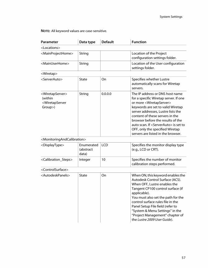
System Settings
57
NOTE: All keyword values are case-sensitive.
Parameter Data type Default Function
<Locations>
<MainProjectHome> String Location of the Project configuration settings folder.
<MainUserHome> String Location of the User configuration settings folder.
<Wiretap>
<ServerAuto> State On Specifies whether Lustre automatically scans for Wiretap servers.
<WiretapServer>(within <WiretapServerGroup>)
String 0.0.0.0 The IP address or DNS host name for a specific Wiretap server. If one or more <WiretapServer> keywords are set to valid Wiretap server addresses, Lustre lists the content of these servers in the browser before the results of the auto scan. If <ServerAuto> is set to OFF, only the specified Wiretap servers are listed in the browser.
<MonitoringAndCalibration>
<DisplayType> Enumerated (abstract data)
LCD Specifies the monitor display type (e.g., LCD or CRT).
<Calibration_Steps> Integer 10 Specifies the number of monitor calibration steps performed.
<ControlSurface>
<AutodeskPanels> State On When ON, this keyword enables the Autodesk Control Surface (ACS). When OFF, Lustre enables the Tangent CP100 control surface (if applicable).You must also set the path for the control surface rules file in the Panel Setup File field (refer to “System & Menu Settings” in the “Project Management” chapter of the Lustre 2009 User Guide).

Software, Project, and User Configuration FilesA
58
<PanelIDs> function=”0”grading=”0”navigation=”0”
The ID numbers for the Function, Navigation, and Grading panels of the ACS. You must manually configure these keywords.If your control surface is a Tangent CP100, Lustre does not use these keywords.
<PanelIPTags> function=”101”grading=”100”navigation=”102”
<Browsed>
<Port> Integer 1055 All computers on the BrowseD network must use the same port to communicate.
<Username> String Administrator Administrative user on the BrowseD server (e.g., root on Linux and Administrator on Windows).
<Password> String xxx Password for the administrative user.
<UseInfi> State Off Switch to ON if the networking protocol to use with BrowseD is the InfiniBand.
<ReadCacheBufferNum>
Integer 0
<ReadCacheThreadNum>
Integer 0
<BrowsedServer>(within <BrowsedServerGroup>)
String 0.0.0.0 Defines the IP address or DNS host name for a specific BrowseD server.
<SlaveRenderer>
<HostName> String The IP address or DNS host name for a specific Slave Render machine.
<Timeout> Integer 5000 Sets the timeout duration (in milliseconds) of the automatic slave renderer detection.
<Backburner>
<Hostname> String The IP address or DNS host name for a specific Backburner Manager machine.
<MatchCustomGroup>
Parameter Data type Default Function

System Settings
59
<MatchCustom> Name “AliasName”type=”s”
Specifies the XML metadata field to be used by the Custom match option selected from the Browse menu.“s” represents string.
<MatchCustom> Name “DPXTimeCode”type=”tc”
“tc” represents timecode.
<MatchCustom> Name “DPXkeycode”type=”kk”
“kk” represents keycode.
<MatchCustom> Name “DPXTapeNAME”type=”s”
“s” represents string.
<MatchCustom> Name “EDLReelName”type=”s”
“s” represents string.
<MatchCustom> Name “DL_EDLClip_name”type=”s”
“s” represents string.
<MatchCustom> Name “DL_edlFrameID”type=”i”
“i” represents integer.
<MatchCustom> Name “DLEDL_startTC”type=”tc”
“tc” represents timecode.
<AVIO>
<PlayoutHighSpeed> State Off When OFF, it refreshes the Player as you are performing a playout.When ON, the Player is no longer refreshed and therefore the performance of the playout improves.If you are using an IBM 6223 workstation, you must set this keyword to ON.
<WTTFirstSDLeadInCorrection>
Integer 1 Sets the delay for the SD first lead-in.
<WTTSubsequentSDLeadInCorrection>
Integer 2 Delays all the lead-ins following the SD first shot.
<WTTSDLeadInIncrement>
Integer 0 Corrects the delay after the SD third shot.
<WTTFirstHDLeadInCorrection>
Integer 0 Sets the delay for the HD first lead-in.
<WTTSubsequentHDLeadInCorrection>
Integer 0 Delays all the lead-ins following the HD first shot.
<WTTHDLeadInIncrement>
Integer 0 Corrects the delay after the HD third shot.
Parameter Data type Default Function

Software, Project, and User Configuration FilesA
60
<Miscellaneous>
<DisablePanScanFrame>
State On
<NVidiaSDISync> State Off
<NVidiaPlayoutDelay> Integer 0
<BlockSize> Integer 2048
<AudioResyncTime> Float -1
<LoadingSetup> Integer 0
<EnableKeykodeSending>
Enumerated (abstract data)
Off
<LoginGUIGain> Float 1.0
<LoginGUIGamma> Float 1.0
<ClusterPlayDelay> Integer 0 Available for Incinerator only.
<ClusterSmoothPlayback>
State Off Available for Incinerator only.
<Debug>
<DumpDLEDLPath> String Path to place the contents of a DLEDL when it is loaded in the timeline or Shot bin.
<DumpWiretapCreateClip>
State Off When ON, the attributes of a Wiretap clip are placed into a log file each time a clip is created on a Wiretap server. The file WiretapClipDump.log is located in the Lustre home folder. Use this keyword for debugging only.
<FilmTypeGroup>
<FilmType> Name Various film types for AGFA, Kodak™, Eastman, and Fuji emulsions. It defines the relationship between the DPX film emulsion code and the DPX film code number.
Parameter Data type Default Function

index
61
Index
BBackburner Manager
configuring 39detecting in Lustre 40detecting with Backburner Server 44installing 39overview 37
Backburner Monitorinstalling 39overview 37
Backburner Serverdetecting Backburner Manager 44overview 37starting 44
background renderingcomponents 36configuring in Lustre 48overview 35related documentation 35setting up render nodes 40setup, workflow 37storage, mounting 41with BrowseD 52
BrowseDaccessing directories from Lustre 51configuring, workflow 50overview 49remote rendering 52starting and stopping 50using 50
browsed.configconfiguring 50
Burn for Lustrehardware and software requirements 41
installing and configuring 43license 45overview 37
CCD-ROM drive, mounting 23configuration file
overview 55configuring
Backburner Manager 39browsed.config 50Burn for Lustre 43
Ddocumentation
about this guide 1conventions 3library, on the Autodesk Web site 3set of guides 1
Ffloating licenses
background rendering 46framestore
initialising on start-up 27
Hhardware
requirements, Burn for Lustre 41
Iinitialising the framestore 27installation

62
Index
overview 4installation requirements 21installing
Backburner Manager 39Backburner Monitor 39Burn for Lustre 43Lustre (Linux) 23
Kkernel, confirming the version 22
Llicense
background rendering, floating 46Burn for Lustre 45
license serverbackground rendering 46
licensinginstalling and acquiring 24requesting license codes 25
Linuxverifying the version 22
logging in as root 22logical volume, assembling LUNs 15LUNs
assembling into logical volume 15checking detection 13checking partition type 14
Lustreaccessing BrowseD directories 51detecting Backburner Manager 40installing (Linux) 23starting 27
Mmount points
overview 37mounting the CD-ROM 23
NNAS
using BrowseD 49
Ooperating system, verifying 22
PPDF documentation, accessing 2projects
setting up slave rendering 34
Rrender nodes
setting up 40rendering
with BrowseD 52root login 22
SSAN
using BrowseD 49slave rendering
configuring, workflow 29setting up Lustre projects 34
softwarerequirements for Burn for Lustre 41
storageconnecting and powering up 10creating the XFS filesystem 18workflow for configuring 9
Wworkflow
configuring BrowseD 50configuring slave rendering 29setting up background rendering 37storage configuration 9
XXFS filesystem 18


![Arrays in Lustre - laure.gonnord.orglaure.gonnord.org/pro/research/ER02_2014/nh_arrays.pdf · Arrays in Lustre-V4 Arrays in Lustre-V4[Rocheteau 92] Introduced for hardware description](https://img.pdfslide.us/doc/110x75/5f6aff17cf1717211a5172da/arrays-in-lustre-laure-arrays-in-lustre-v4-arrays-in-lustre-v4rocheteau-92.jpg)