Embed Size (px)
Citation preview

© 2007 The McGraw-Hill Companies, Inc. All rights reserved.
Vector Mechanics for Engineers: Statics
Eig
ht
hEd
ition
2 - 1
CE 102 Statics
Chapter 2
Statics of Particles

© 2007 The McGraw-Hill Companies, Inc. All rights reserved.
Vector Mechanics for Engineers: Statics
Eig
ht
hEd
ition
2 - 2
Contents
Introduction
Resultant of Two Forces
Vectors
Addition of Vectors
Resultant of Several Concurrent Forces
Sample Problem 2.1
Sample Problem 2.2
Rectangular Components of a Force: Unit Vectors
Addition of Forces by Summing Components
Sample Problem 2.3
Equilibrium of a Particle
Free-Body Diagrams
Sample Problem 2.4
Sample Problem 2.5
Rectangular Components in Space
Sample Problem 2.6

© 2007 The McGraw-Hill Companies, Inc. All rights reserved.
Vector Mechanics for Engineers: Statics
Eig
ht
hEd
ition
2 - 3
Introduction
• The objective for the current chapter is to investigate the effects of forces on particles:
- replacing multiple forces acting on a particle with a single equivalent or resultant force,
- relations between forces acting on a particle that is in a state of equilibrium.
• The focus on particles does not imply a restriction to miniscule bodies. Rather, the study is restricted to analyses in which the size and shape of the bodies is not significant so that all forces may be assumed to be applied at a single point.

© 2007 The McGraw-Hill Companies, Inc. All rights reserved.
Vector Mechanics for Engineers: Statics
Eig
ht
hEd
ition
2 - 4
Resultant of Two Forces
• force: action of one body on another; characterized by its point of application, magnitude, line of action, and sense.
• Experimental evidence shows that the combined effect of two forces may be represented by a single resultant force.
• The resultant is equivalent to the diagonal of a parallelogram which contains the two forces in adjacent legs.
• Force is a vector quantity.

© 2007 The McGraw-Hill Companies, Inc. All rights reserved.
Vector Mechanics for Engineers: Statics
Eig
ht
hEd
ition
2 - 5
Vectors• Vector: parameters possessing magnitude and direction
which add according to the parallelogram law. Examples: displacements, velocities, accelerations.
• Vector classifications:- Fixed or bound vectors have well defined points of
application that cannot be changed without affecting an analysis.
- Free vectors may be freely moved in space without changing their effect on an analysis.
- Sliding vectors may be applied anywhere along their line of action without affecting an analysis.
• Equal vectors have the same magnitude and direction.
• Negative vector of a given vector has the same magnitude and the opposite direction.
• Scalar: parameters possessing magnitude but not direction. Examples: mass, volume, temperature

© 2007 The McGraw-Hill Companies, Inc. All rights reserved.
Vector Mechanics for Engineers: Statics
Eig
ht
hEd
ition
2 - 6
Addition of Vectors
• Trapezoid rule for vector addition
• Triangle rule for vector addition
B
B
C
C
QPRBPQQPR
cos2222
• Law of cosines,
• Law of sines,
A
C
R
B
Q
A sinsinsin
• Vector addition is commutative,
PQQP
• Vector subtraction

© 2007 The McGraw-Hill Companies, Inc. All rights reserved.
Vector Mechanics for Engineers: Statics
Eig
ht
hEd
ition
2 - 7
Addition of Vectors
• Addition of three or more vectors through repeated application of the triangle rule
• The polygon rule for the addition of three or more vectors.
• Vector addition is associative,
SQPSQPSQP
• Multiplication of a vector by a scalar

© 2007 The McGraw-Hill Companies, Inc. All rights reserved.
Vector Mechanics for Engineers: Statics
Eig
ht
hEd
ition
2 - 8
Resultant of Several Concurrent Forces
• Concurrent forces: set of forces which all pass through the same point.
A set of concurrent forces applied to a particle may be replaced by a single resultant force which is the vector sum of the applied forces.
• Vector force components: two or more force vectors which, together, have the same effect as a single force vector.

© 2007 The McGraw-Hill Companies, Inc. All rights reserved.
Vector Mechanics for Engineers: Statics
Eig
ht
hEd
ition
2 - 9
Sample Problem 2.1
The two forces act on a bolt at A. Determine their resultant.
SOLUTION:
• Graphical solution - construct a parallelogram with sides in the same direction as P and Q and lengths in proportion. Graphically evaluate the resultant which is equivalent in direction and proportional in magnitude to the the diagonal.
• Trigonometric solution - use the triangle rule for vector addition in conjunction with the law of cosines and law of sines to find the resultant.

© 2007 The McGraw-Hill Companies, Inc. All rights reserved.
Vector Mechanics for Engineers: Statics
Eig
ht
hEd
ition
2 - 10
Sample Problem 2.1
• Graphical solution - A parallelogram with sides equal to P and Q is drawn to scale. The magnitude and direction of the resultant or of the diagonal to the parallelogram are measured,
35N 98 R
• Graphical solution - A triangle is drawn with P and Q head-to-tail and to scale. The magnitude and direction of the resultant or of the third side of the triangle are measured,
35N 98 R

© 2007 The McGraw-Hill Companies, Inc. All rights reserved.
Vector Mechanics for Engineers: Statics
Eig
ht
hEd
ition
2 - 11
Sample Problem 2.1• Trigonometric solution - Apply the triangle rule.
From the Law of Cosines,
155cosN60N402N60N40
cos222
222 BPQQPR
AA
R
QBA
R
B
Q
A
2004.15
N73.97
N60155sin
sinsin
sinsin
N73.97R
From the Law of Sines,
04.35

© 2007 The McGraw-Hill Companies, Inc. All rights reserved.
Vector Mechanics for Engineers: Statics
Eig
ht
hEd
ition
2 - 12
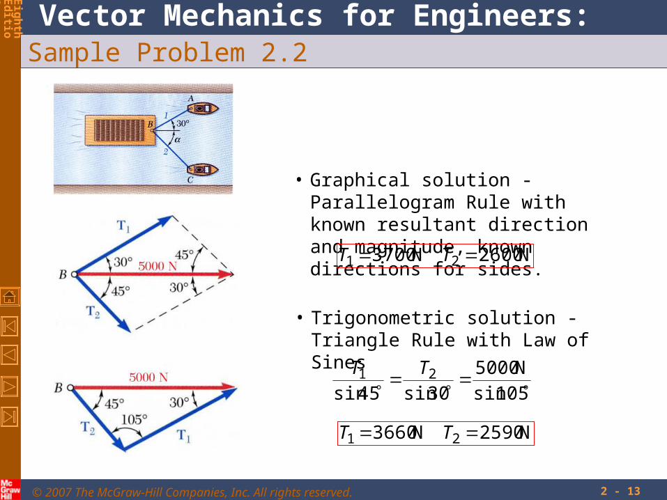
Sample Problem 2.2
a) the tension in each of the ropes for = 45o,
b) the value of for which the tension in rope 2 is a minimum.
A barge is pulled by two tugboats. If the resultant of the forces exerted by the tugboats is 5000 N directed along the axis of the barge, determine
SOLUTION:
• Find a graphical solution by applying the Parallelogram Rule for vector addition. The parallelogram has sides in the directions of the two ropes and a diagonal in the direction of the barge axis and length proportional to 5000 N.
• The angle for minimum tension in rope 2 is determined by applying the Triangle Rule and observing the effect of variations in .
• Find a trigonometric solution by applying the Triangle Rule for vector addition. With the magnitude and direction of the resultant known and the directions of the other two sides parallel to the ropes given, apply the Law of Sines to find the rope tensions.
© 2007 The McGraw-Hill Companies, Inc. All rights reserved.
Vector Mechanics for Engineers: Statics
Eig
ht
hEd
ition
2 - 13
Sample Problem 2.2
• Graphical solution - Parallelogram Rule with known resultant direction and magnitude, known directions for sides.
N2600N3700 21 TT
• Trigonometric solution - Triangle Rule with Law of Sines
105sin
N5000
30sin45sin21 TT
N2590N3660 21 TT

© 2007 The McGraw-Hill Companies, Inc. All rights reserved.
Vector Mechanics for Engineers: Statics
Eig
ht
hEd
ition
2 - 14
Sample Problem 2.2
• The angle for minimum tension in rope 2 is determined by applying the Triangle Rule and observing the effect of variations in .
• The minimum tension in rope 2 occurs when T1 and T2 are perpendicular.
30sinN50002T N25002 T
30cosN50001T N43301 T
3090 60

© 2007 The McGraw-Hill Companies, Inc. All rights reserved.
Vector Mechanics for Engineers: Statics
Eig
ht
hEd
ition
2 - 15
Rectangular Components of a Force: Unit Vectors
• Vector components may be expressed as products of the unit vectors with the scalar magnitudes of the vector components.
Fx and Fy are referred to as the scalar components of
jFiFF yx
F
• May resolve a force vector into perpendicular components so that the resulting parallelogram is a rectangle. are referred to as rectangular vector components and
yx FFF
yx FF
and
• Define perpendicular unit vectors which are parallel to the x and y axes.
ji
and

© 2007 The McGraw-Hill Companies, Inc. All rights reserved.
Vector Mechanics for Engineers: Statics
Eig
ht
hEd
ition
2 - 16
Addition of Forces by Summing Components
SQPR
• Wish to find the resultant of 3 or more concurrent forces,
jSQPiSQP
jSiSjQiQjPiPjRiR
yyyxxx
yxyxyxyx
• Resolve each force into rectangular components
x
xxxxF
SQPR
• The scalar components of the resultant are equal to the sum of the corresponding scalar components of the given forces.
y
yyyy
F
SQPR
x
yyx R
RRRR 122 tan
• To find the resultant magnitude and direction,

© 2007 The McGraw-Hill Companies, Inc. All rights reserved.
Vector Mechanics for Engineers: Statics
Eig
ht
hEd
ition
2 - 17
Sample Problem 2.3
Four forces act on bolt A as shown. Determine the resultant of the force on the bolt.
SOLUTION:
• Resolve each force into rectangular components.
• Calculate the magnitude and direction of the resultant.
• Determine the components of the resultant by adding the corresponding force components.

© 2007 The McGraw-Hill Companies, Inc. All rights reserved.
Vector Mechanics for Engineers: Statics
Eig
ht
hEd
ition
2 - 18
Sample Problem 2.3SOLUTION:
• Resolve each force into rectangular components.
9.256.96100
0.1100110
2.754.2780
0.759.129150
4
3
2
1
F
F
F
F
compycompxmagforce
22 3.141.199 R N6.199R
• Calculate the magnitude and direction.
N1.199
N3.14tan 1.4
• Determine the components of the resultant by adding the corresponding force components.
1.199xR 3.14yR

© 2007 The McGraw-Hill Companies, Inc. All rights reserved.
Vector Mechanics for Engineers: Statics
Eig
ht
hEd
ition
2 - 19
Equilibrium of a Particle• When the resultant of all forces acting on a particle is zero, the particle is
in equilibrium.
• Particle acted upon by two forces:
- equal magnitude
- same line of action
- opposite sense
• Particle acted upon by three or more forces:
- graphical solution yields a closed polygon
- algebraic solution
00
0
yx FF
FR
• Newton’s First Law: If the resultant force on a particle is zero, the particle will remain at rest or will continue at constant speed in a straight line.

© 2007 The McGraw-Hill Companies, Inc. All rights reserved.
Vector Mechanics for Engineers: Statics
Eig
ht
hEd
ition
2 - 20
Free-Body Diagrams
Space Diagram: A sketch showing the physical conditions of the problem.
Free-Body Diagram: A sketch showing only the forces on the selected particle.

© 2007 The McGraw-Hill Companies, Inc. All rights reserved.
Vector Mechanics for Engineers: Statics
Eig
ht
hEd
ition
2 - 21
Sample Problem 2.4
In a ship-unloading operation, a 3500-N automobile is supported by a cable. A rope is tied to the cable and pulled to center the automobile over its intended position. What is the tension in the rope?
SOLUTION:
• Construct a free-body diagram for the particle at the junction of the rope and cable.
• Apply the conditions for equilibrium by creating a closed polygon from the forces applied to the particle.
• Apply trigonometric relations to determine the unknown force magnitudes.

© 2007 The McGraw-Hill Companies, Inc. All rights reserved.
Vector Mechanics for Engineers: Statics
Eig
ht
hEd
ition
2 - 22
Sample Problem 2.4
SOLUTION:
• Construct a free-body diagram for the particle at A.
• Apply the conditions for equilibrium.
• Solve for the unknown force magnitudes.
58sin
N3500
2sin120sinACAB TT
N3570ABT
N144ACT

© 2007 The McGraw-Hill Companies, Inc. All rights reserved.
Vector Mechanics for Engineers: Statics
Eig
ht
hEd
ition
2 - 23
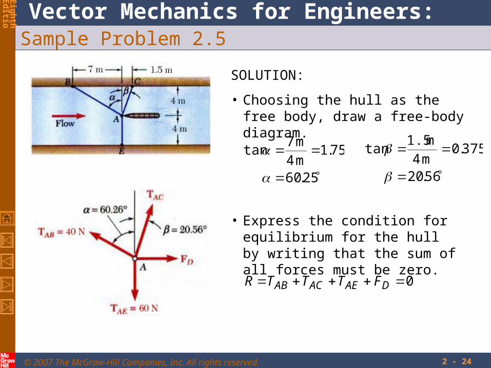
Sample Problem 2.5
It is desired to determine the drag force at a given speed on a prototype sailboat hull. A model is placed in a test channel and three cables are used to align its bow on the channel centerline. For a given speed, the tension is 40 N in cable AB and 60 N in cable AE.
Determine the drag force exerted on the hull and the tension in cable AC.
SOLUTION:
• Choosing the hull as the free body, draw a free-body diagram.
• Express the condition for equilibrium for the hull by writing that the sum of all forces must be zero.
• Resolve the vector equilibrium equation into two component equations. Solve for the two unknown cable tensions.
© 2007 The McGraw-Hill Companies, Inc. All rights reserved.
Vector Mechanics for Engineers: Statics
Eig
ht
hEd
ition
2 - 24
Sample Problem 2.5
SOLUTION:
• Choosing the hull as the free body, draw a free-body diagram.
25.60
75.1m 4
m 7tan
56.20
375.0m 4
m 1.5tan
• Express the condition for equilibrium for the hull by writing that the sum of all forces must be zero.
0 DAEACAB FTTTR
© 2007 The McGraw-Hill Companies, Inc. All rights reserved.
Vector Mechanics for Engineers: Statics
Eig
ht
hEd
ition
2 - 25
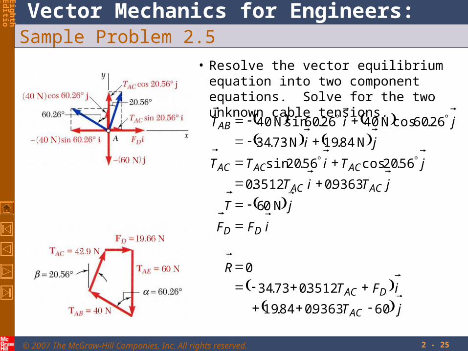
Sample Problem 2.5
• Resolve the vector equilibrium equation into two component equations. Solve for the two unknown cable tensions.
jT
iFT
R
iFF
jT
jTiT
jTiTT
ji
jiT
AC
DAC
DD
ACAC
ACACAC
AB
609363.084.19
3512.073.34
0
N 06
9363.03512.0
56.20cos56.20sin
N 84.19N 73.34
26.60cosN 4026.60sinN 40

© 2007 The McGraw-Hill Companies, Inc. All rights reserved.
Vector Mechanics for Engineers: Statics
Eig
ht
hEd
ition
2 - 26
Sample Problem 2.5
jT
iFT
R
AC
DAC
609363.084.19
3512.073.34
0
This equation is satisfied only if each component of the resultant is equal to zero.
609363.084.1900
3512.073.3400
ACy
DACx
TF
FTF
N 66.19
N 9.42
D
AC
F
T

© 2007 The McGraw-Hill Companies, Inc. All rights reserved.
Vector Mechanics for Engineers: Statics
Eig
ht
hEd
ition
2 - 27
Rectangular Components in Space
• The vector is contained in the plane OBAC.
F
• Resolve into horizontal and vertical components.
yh FF sin
F
yy FF cos
• Resolve into rectangular components.
hF
sinsin
sin
cossin
cos
y
hz
y
hx
F
FF
F
FF

© 2007 The McGraw-Hill Companies, Inc. All rights reserved.
Vector Mechanics for Engineers: Statics
Eig
ht
hEd
ition
2 - 28
Rectangular Components in Space
• With the angles between and the axes,F
kji
F
kjiF
kFjFiFF
FFFFFF
zyx
zyx
zyx
zzyyxx
coscoscos
coscoscos
coscoscos
• is a unit vector along the line of action ofand are the direction cosines for
F
F
zyx cos and,cos,cos

© 2007 The McGraw-Hill Companies, Inc. All rights reserved.
Vector Mechanics for Engineers: Statics
Eig
ht
hEd
ition
2 - 29
Rectangular Components in Space
Direction of the force is defined by the location of two points,
222111 ,, and ,, zyxNzyxM
d
FdF
d
FdF
d
FdF
kdjdidd
FF
zzdyydxxd
kdjdid
NMd
zz
yy
xx
zyx
zyx
zyx
1
and joining vector
121212

© 2007 The McGraw-Hill Companies, Inc. All rights reserved.
Vector Mechanics for Engineers: Statics
Eig
ht
hEd
ition
2 - 30
Sample Problem 2.6
The tension in the guy wire is 2500 N. Determine:
a) components Fx, Fy, Fz of the force acting on the bolt at A,
b) the angles x, y, zdefining the direction of the force
SOLUTION:
• Based on the relative locations of the points A and B, determine the unit vector pointing from A towards B.
• Apply the unit vector to determine the components of the force acting on A.
• Noting that the components of the unit vector are the direction cosines for the vector, calculate the corresponding angles.

© 2007 The McGraw-Hill Companies, Inc. All rights reserved.
Vector Mechanics for Engineers: Statics
Eig
ht
hEd
ition
2 - 31
Sample Problem 2.6SOLUTION:
• Determine the unit vector pointing from A towards B.
m 3.94
m30m80m40
m30m80m40
222
AB
kjiAB
• Determine the components of the force.
kji
kji
FF
N 795N 2120N1060
318.0848.0424.0N 2500
kji
kji
318.0848.0424.0
3.94
30
3.94
80
3.94
40

© 2007 The McGraw-Hill Companies, Inc. All rights reserved.
Vector Mechanics for Engineers: Statics
Eig
ht
hEd
ition
2 - 32
Sample Problem 2.6• Noting that the components of the unit vector are
the direction cosines for the vector, calculate the corresponding angles.
kji
kji zyx
318.0848.0424.0
coscoscos
5.71
0.32
1.115
z
y
x

33
Problem 2.7
The direction of the 75-lbforces may vary, but theangle between the forcesis always 50o. Determinethe value of for whichthe resultant of the forcesacting at A is directedhorizontally to the left.
240 lb
30o
50o75 lb
75 lb
A

34
Solving Problems on Your Own
1. Determine the resultant R of two or more forces.
2. Draw a parallelogram with the applied forces as two adjacent sides and the resultant as the included diagonal.
3. Set the resultant, or sum of the forces, directed horizontally.
The direction of the 75-lbforces may vary, but theangle between the forcesis always 50o. Determinethe value of for whichthe resultant of the forcesacting at A is directedhorizontally to the left.
240 lb
30o
50o75 lb
75 lb
A
Problem 2.7

35
Problem 2.7 Solution
Determine the resultant R of twoor more forces.
We first Replace the two 75-lbforces by their resultant R1, usingthe triangle rule.
50o
25o
25oR1
R1 = 2(75 lb) cos25o = 135.95 lb
R1 = 135.95 lb +25o
240 lb
30o
50o75 lb
75 lb
A

36
Draw a parallelogram with the applied forces as two adjacentsides and the resultant as the included diagonal. Set the resultant, or sum of the forces, directed horizontally.
Problem 2.7 Solution
30o +25o
R2
R1 = 135.95 lb240 lb
Consider the resultant R2
of R1 and the 240-lb forceand recall that R2 must behorizontal and directed tothe left.
Law of sines:
sin(+25o)240 lb
=sin(30o)
135.95 lb
sin(+25o) = (240 lb) sin(30o)
135.95 lb= 0.88270
+ 25o = 61.97o
= 37.0o

37
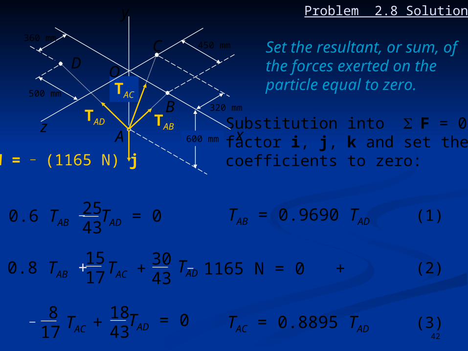
Problem 2.8
A container of weight W = 1165 N is supportedby three cables as shown.Determine the tension ineach cable.600 mm
320 mm
450 mm360 mm
500 mm
DO
C
B
A x
y
z

38
A container of weight W = 1165 N is supportedby three cables as shown.Determine the tension ineach cable.
Solving Problems on Your Own
1. Draw a free-body diagram of the particle. This diagram shows the particle and all the forces acting on it.
2. Resolve each of the forces into rectangular components. Follow the method outlined in the text.
F = F = (dx i + dy j + dz k) Fd
600 mm
320 mm
450 mm360 mm
500 mm
DO
C
B
A x
y
z
Problem 2.8

39
3. Set the resultant, or sum, of the forces exerted on the particle equal to zero. You will obtain a vectorial equation consisting of terms containing the unit vectors i, j, and k. Three scalar equations result, which can be solved for the unknowns.
Solving Problems on Your Own
A container of weight W = 1165 N is supportedby three cables as shown.Determine the tension ineach cable.
600 mm
320 mm
450 mm360 mm
500 mm
DO
C
B
A x
y
z
Problem 2.8

40
Problem 2.8 Solution
F = 0
TAB + TAC + TAD + W = 0
AB = (450 mm)i + (600 mm)j AB = 750 mm
AC = (600 mm)j _ (320mm)k AC = 680 mm
AD = (_500 mm)i + (600 mm)j + (360 mm)k AD = 860 mm
600 mm
320 mm
450 mm360 mm
500 mm
DC
B
A x
y
zTAD TAB
TAC
W = _ (1165 N) j
O
Draw a free-body diagram of the particle.

41
( )450750
i +600750
j TAB
= (0.6 i + 0.8 j) TAB
TAB = TAB AB = TAB ABAB
=
= =600 mm
320 mm
450 mm360 mm
500 mm
DC
B
A x
y
zTAD TAB
TAC
W = _ (1165 N) j
O
TAD ADAD
= TAD = TAD AD = ( )TAD
500860
i +600860
j +360860
k
=( ) TAD
25 43
i + 30 43
j + 18 43
k
=
Resolve each of the forces into rectangular components.
Problem 2.8 Solution
TAC ACAC ( )680 j _
320680
k TAC= TAC = TAC AC = ( )1517
j _= 817
k600TAC
42
Substitution into F = 0,factor i, j, k and set theircoefficients to zero:
0.6 TAB _ 2543
TAD = 0 TAB = 0.9690 TAD (1)
0.8 TAB + 1517
TAC3043
TAD+ _ 1165 N = 0 (2)
817
_ TAC +1843
TAD = 0
+
TAC = 0.8895 TAD (3)
600 mm
320 mm
450 mm360 mm
500 mm
DC
B
A x
y
zTAD TAB
TAC
W = _ (1165 N) j
O
Set the resultant, or sum, ofthe forces exerted on theparticle equal to zero.
Problem 2.8 Solution

43
Substitution for TAB andTAC from (1) and (3)into (2):
( 0.8 x 0.9690 + x 0.8895 + )TAD _ 1165 N = 01517
3043
2.2578 TAD _ 1165 N = 0
From (1): TAB = 0.9690 (516 N)
From (3): TAC = 0.8895 (516 N)
TAD = 516 N
TAB = 500 N
TAC = 459 N
600 mm
320 mm
450 mm360 mm
500 mm
DC
B
A x
y
zTAD TAB
TAC
W = _ (1165 N) j
O
Problem 2.8 Solution

44
Problem 2.9
Cable AB is 65 ft long, andthe tension in that cable is3900 lb. Determine (a) thex, y, and z components ofthe force exerted by thecable on the anchor B, (b)the angles x, y, and z
defining the direction ofthat force.
O
x
y
z
56 ft
D
B
C
A
50o 20o

45
Solving Problems on Your Own
O
x
y
z
56 ft
D
B
C
A
50o 20o
Cable AB is 65 ft long, andthe tension in that cable is3900 lb. Determine (a) thex, y, and z components ofthe force exerted by thecable on the anchor B, (b)the angles x, y, and z
defining the direction ofthat force.
1. Determine the rectangular components of a force defined byits magnitude and direction. If the direction of the force F isdefined by the angles y and , projections of F through theseangles or their components will yield the components of F.
Problem 2.9

46
Solving Problems on Your Own
Cable AB is 65 ft long, andthe tension in that cable is3900 lb. Determine (a) thex, y, and z components ofthe force exerted by thecable on the anchor B, (b)the angles x, y, and z
defining the direction ofthat force.
2. Determine the direction cosines of the line of action of a force.The direction cosines of the line of action of a force F aredetermined by dividing the components of the force by F.
cos x=Fx
F cos y=Fy
F cos z=Fz
F
O
x
y
z
56 ft
D
B
C
A
50o 20o
Problem 2.9

47
Problem 2.9 Solution
z
y
Determine the direction cosines ofthe line of action of a force.
O
x
B
A
Fy
Fz
F
Fx
20o
y
65 ftFrom triangle AOB:
cos y = 56 ft65 ft
= 0.86154
y = 30.51o
(a) Fx = _ F sin y cos 20o
= _ (3900 lb) sin 30.51o cos 20o
Fx = _1861 lb
Fy = + F cos y = (3900 lb)(0.86154) Fy = + 3360 lb
Fz = + (3900 lb) sin 30.51o sin 20o Fz = + 677 lb
56 ft

48
Problem 2.9 Solution
O
x
B
A
Fy
Fz
F
Fx
20o
y
65 ft
y
Determine the direction cosinesof the line of action of a force.
(b) cos x = Fx
F=
_1861 lb3900 lb
cos x = _ 0.4771
x = 118.5o
From above (a): y = 30.5o
cos z = Fz
F= + 677 lb
3900 lb= + 0.1736 z = 80.0o
56 ft

49
Problem 2.10
A
9 ft
5 ft
8.5 ft
12 ft 7.5 ft
Two cables are tiedtogether at C andloaded as shown.determine the tension(a) in cable AC,(b) in cable BC.
B
C
396 lb

50
Solving Problems on Your Own
Two cables are tiedtogether at C andloaded as shown.determine the tension(a) in cable AC,(b) in cable BC.
A
9 ft
5 ft
8.5 ft
12 ft 7.5 ft
B
C
396 lb
1. Draw a free-body diagram of the particle. This diagram shows the particle and all the forces acting on it.
2. Set the resultant, or sum, of the forces exerted on the particle equal to zero. You will obtain a vectorial equation consisting of terms containing the unit vectors i, j, and k. Three scalar equations result, which can be solved for the unknowns.
Problem 2.10

51
x
y
TAC
TBC
4
7.512
3.58.512.5
396 lb
FREE BODY C:
TBC = 0 Fx = 0 : 1212.5
TAC7.58.5+
TBC = 1.088 TAC
Fy = 0 : TAC 48.5+
3.512.5 TBC 396 lb = 0
Problem 2.10 Solution
Draw a free-body diagramof the particle.
Set the resultant, or sum, ofthe forces exerted on theparticle equal to zero.

52
x
y
TAC
TBC
4
7.512
3.58.512.5
396 lb
(a) Substitute for TBC:
TAC 48.5+
3.512.5 (1.088 TAC )
_ 396 lb = 0
(0.280 + 0.512) TAC _ 396 lb = 0
(b) TBC = 1.088 (500 lb)
TAC = 500 lb
TBC = 544 lb
Problem 2.10 Solution

53
Problem 2.11
Collars A and B are connectedby a 25-in.-long wire and canslide freely on frictionless rods.If a 60-lb force Q is applied tocollar B as shown, Determine(a) the tension in the wire whenx = 9 in., (b) the correspondingmagnitude of the force P requiredto maintain the equilibrium ofthe system.
yx
x
20 in
A
B
O
z
z
P
Q

54
yx
x
20 in
A
B
O
z
z
P
Q
1. Draw a free-body diagram of the particle. This diagram shows the particle and all the forces acting on it.
Solving Problems on Your Own
Collars A and B are connectedby a 25-in.-long wire and canslide freely on frictionless rods.If a 60-lb force Q is applied tocollar B as shown, Determine(a) the tension in the wire whenx = 9 in., (b) the correspondingmagnitude of the force P requiredto maintain the equilibrium ofthe system.
Problem 2.11

55
2. Set the resultant, or sum, of the forces exerted on the particle equal to zero. You will obtain a vectorial equation consisting of terms containing the unit vectors i, j, and k. Three scalar equations result, which can be solved for the unknowns.
yx
x
20 in
A
B
O
z
z
P
Q
Solving Problems on Your Own
Collars A and B are connectedby a 25-in.-long wire and canslide freely on frictionless rods.If a 60-lb force Q is applied tocollar B as shown, Determine(a) the tension in the wire whenx = 9 in., (b) the correspondingmagnitude of the force P requiredto maintain the equilibrium ofthe system.
Problem 2.11

56
Problem 2.11 Solutionyx
x
20 in
A
B
O
z
z
P
Q
AB = ABAB =
_ x i _ (20 in) j + z k25 in
Draw a free-body diagram of the particle.
Ny j
Nz k
TAB AB
P i
A
Free Body: Collar A
F = 0: P i + Ny j + Nz k + TAB AB = 0
Substitute for AB and set coefficients
of i equal to zero:
P _ TAB x
25= 0 (1)

57
Problem 2.11 SolutionNy j
Nx i
_ TAB AB
Q = (60 lb) k
Free Body: Collar B
F = 0: (60 lb) k + Nx i + Ny j _ TAB AB = 0
Substitute for AB and set coefficients
of k equal to zero:
60 _ TAB z
25= 0 (2)
(a) Since x = 9 in.: (9 in)2 + (20 in) 2 + z 2 = (25 in) 2 z = 12 in
From eq. (2): 60 _ TAB (12)
25= 0 TAB = 125.0 lb
(b) From eq. (1): P =(125.0 lb)(9 in)
25 inP = 45.0 lb
B