Embed Size (px)
Citation preview

© 2006 ETFA 2006, ABB
Standard Redundancy Methods for Highly Available Automation Networks
rationales behind the upcoming IEC 62439 standard
Hubert Kirrmann
ABB Switzerland Ltd,
Corporate Research
© 2
006
ET
FA
, AB
B, 2
20
06-0
9-21
Pra
gStandard Redundancy in Industrial Ethernet Scope
The good thing about “Industrial Ethernet” standards is that there are so manyto choose from (IEC 61784) - you can even make your own.
It remains to be proved that the new networks are more reliable than the field busses that they are supposed to replace.
However, customers require the new technology to be “at least as dependable as the one it replaces”
But few “Industrial Ethernets” care about redundancy.
This talk shows what must be looked at when considering automation network redundancy and which solutions IEC 62439 proposes

© 2
006
ET
FA
, AB
B, 3
20
06-0
9-21
Pra
gStandard Redundancy in Industrial Ethernet
1. Terms: availability and redundancy
2. Classification of requirements
3. Levels of device and network redundancy
4. Ethernet-based automation networks
5. Parallel (static) and serial (dynamic) redundancy
6. IEC 62439 solutions
7. Conclusion

© 2
006
ET
FA
, AB
B, 4
20
06-0
9-21
Pra
gStandard Redundancy in Industrial Ethernet Some terms
Availability applies to repairable systems
Availability is the fraction of time a system is in the “up” (capable of operation) state.
We consider systems in which availability is increased by introducing redundancy(availability could also be increased by better parts, maintenance)
Redundancy is any resource that would not be needed if there were no failures.
We consider automatic insertion of redundancy in case of failure (fault-tolerant systems)and automatic reinsertion after repair.
© 2
006
ET
FA
, AB
B, 5
20
06-0
9-21
Pra
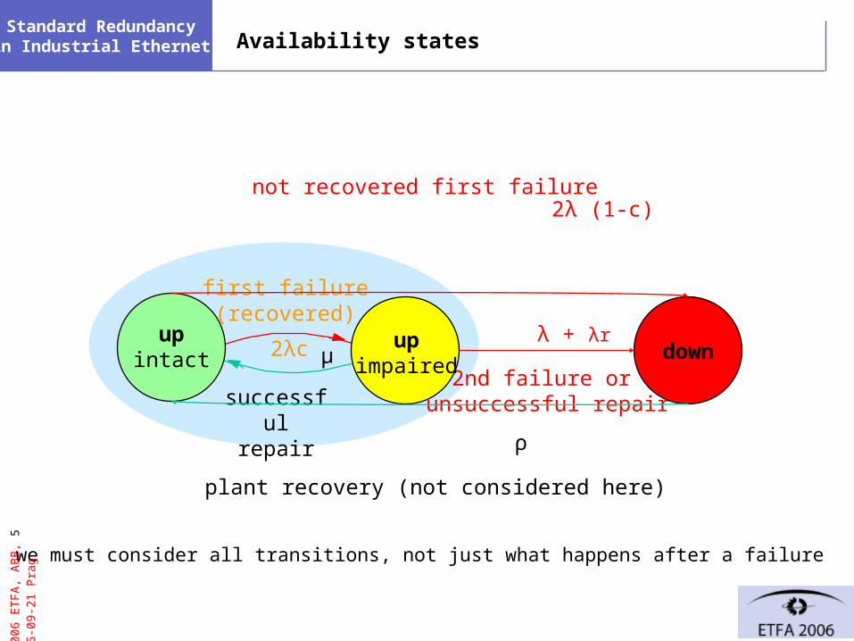
gStandard Redundancy in Industrial Ethernet Availability states
first failure(recovered)
successfulrepair
2nd failure or unsuccessful repair
not recovered first failure
downup
intactup
impaired
plant recovery (not considered here)
λ + λr
2λ (1-c)
2λc μ
ρ
we must consider all transitions, not just what happens after a failure
© 2
006
ET
FA
, AB
B, 6
20
06-0
9-21
Pra
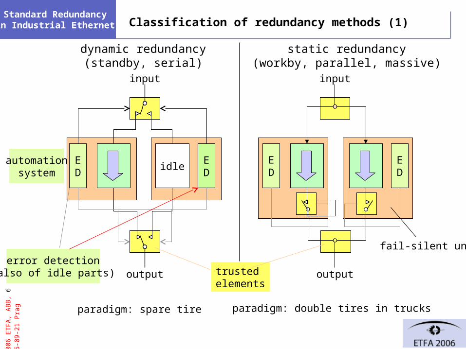
gStandard Redundancy in Industrial Ethernet Classification of redundancy methods (1)
static redundancy(workby, parallel, massive)
dynamic redundancy(standby, serial)
idle
input
ED
ED
ED
ED
output
input
outputtrustedelements
fail-silent unit
error detection(also of idle parts)
paradigm: spare tire paradigm: double tires in trucks
automationsystem
© 2
006
ET
FA
, AB
B, 7
20
06-0
9-21
Pra
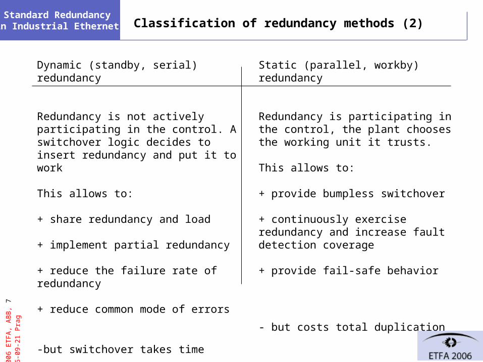
gStandard Redundancy in Industrial Ethernet Classification of redundancy methods (2)
Dynamic (standby, serial) redundancy
Redundancy is not actively participating in the control. A switchover logic decides to insert redundancy and put it to work
This allows to:
+ share redundancy and load
+ implement partial redundancy
+ reduce the failure rate of redundancy
+ reduce common mode of errors
-but switchover takes time
Static (parallel, workby) redundancy
Redundancy is participating in the control, the plant chooses the working unit it trusts.
This allows to:
+ provide bumpless switchover
+ continuously exercise redundancy and increase fault detection coverage
+ provide fail-safe behavior
- but costs total duplication
© 2
006
ET
FA
, AB
B, 8
20
06-0
9-21
Pra
gStandard Redundancy in Industrial Ethernet
1. Terms: availability and redundancy
2. Classification of requirements
3. Levels of device and network redundancy
4. Industrial Ethernet topologies
5. Industrial Ethernet stack and redundancy
6. IEC 62439 solutions
7. Conclusion
© 2
006
ET
FA
, AB
B, 9
20
06-0
9-21
Pra
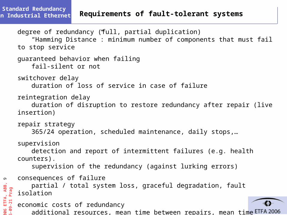
gStandard Redundancy in Industrial Ethernet Requirements of fault-tolerant systems
degree of redundancy (full, partial duplication)“Hamming Distance”: minimum number of components that must fail to stop service
guaranteed behavior when failingfail-silent or not
switchover delayduration of loss of service in case of failure
reintegration delayduration of disruption to restore redundancy after repair (live insertion)
repair strategy365/24 operation, scheduled maintenance, daily stops,…
supervisiondetection and report of intermittent failures (e.g. health counters).supervision of the redundancy (against lurking errors)
consequences of failurepartial / total system loss, graceful degradation, fault isolation
economic costs of redundancyadditional resources, mean time between repairs, mean time between system failure
factors depending on environment (failure rate, repair rate) are not considered here.
© 2
006
ET
FA
, AB
B, 1
0 20
06-0
9-21
Pra
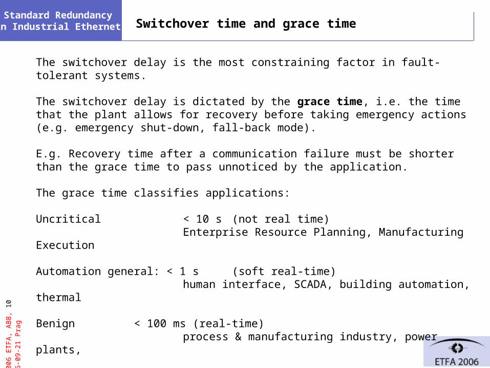
gStandard Redundancy in Industrial Ethernet Switchover time and grace time
The switchover delay is the most constraining factor in fault-tolerant systems.
The switchover delay is dictated by the grace time, i.e. the time that the plant allows for recovery before taking emergency actions (e.g. emergency shut-down, fall-back mode).
E.g. Recovery time after a communication failure must be shorter than the grace time to pass unnoticed by the application.
The grace time classifies applications:
Uncritical < 10 s (not real time)Enterprise Resource Planning, Manufacturing Execution
Automation general: < 1 s (soft real-time)human interface, SCADA, building automation, thermal
Benign < 100 ms (real-time)process & manufacturing industry, power plants,
Critical: < 10 ms (hard real time) synchronized drives, robot control, substations, X-by-wire
© 2
006
ET
FA
, AB
B, 1
1 20
06-0
9-21
Pra
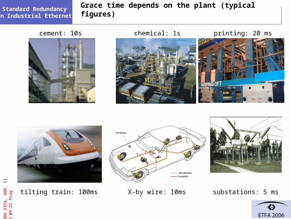
gStandard Redundancy in Industrial Ethernet Grace time depends on the plant (typical figures)
chemical: 1scement: 10s
tilting train: 100ms X-by wire: 10ms substations: 5 ms
printing: 20 ms

© 2
006
ET
FA
, AB
B, 1
2 20
06-0
9-21
Pra
gStandard Redundancy in Industrial Ethernet
1. Terms: availability and redundancy
2. Classification of requirements
3. Levels of device and network redundancy
4. Industrial Ethernet topologies
5. Industrial Ethernet stack and redundancy
6. IEC 62439 solutions
7. Conclusion

© 2
006
ET
FA
, AB
B, 1
3 20
06-0
9-21
Pra
gStandard Redundancy in Industrial Ethernet Automation Networks
We consider networks for automation systems, consisting ofnodes, switches and links.
engineeringworkplace
Field Bus
Firewall
Plant Network / Intranet
Field Bus
Client/server Network
3rd party application server
applicationserver
dbserver
Workplaces(clients)
Enterprise Optimization
(clients)
MobileOperator
connectivityserver
Control Network
ProgrammableLogic Controller
RedundantPLC
touch-screen
© 2
006
ET
FA
, AB
B, 1
4 20
06-0
9-21
Pra
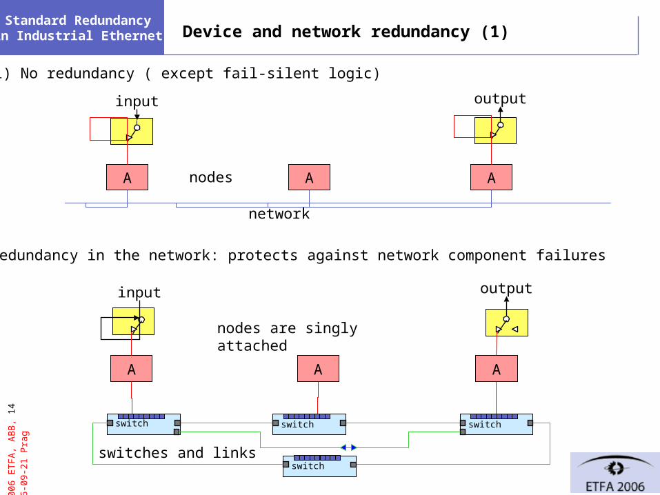
gStandard Redundancy in Industrial Ethernet Device and network redundancy (1)
1) No redundancy ( except fail-silent logic)
A A A
input output
2) Redundancy in the network: protects against network component failures
A A A
input output
switch switch switch
switch
network
nodes
nodes are singly attached
switches and links
© 2
006
ET
FA
, AB
B, 1
5 20
06-0
9-21
Pra
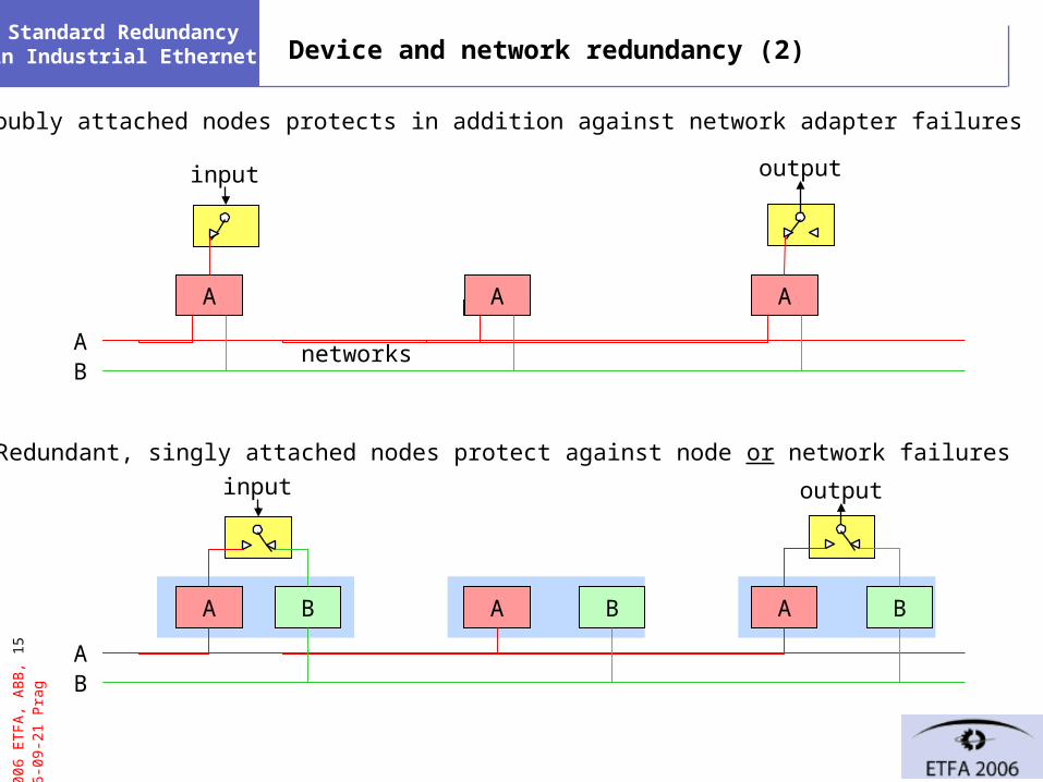
gStandard Redundancy in Industrial Ethernet Device and network redundancy (2)
3) Doubly attached nodes protects in addition against network adapter failures
A A A
A B
input output
4) Redundant, singly attached nodes protect against node or network failures
A A A
A
B B B
B
input output
networks
© 2
006
ET
FA
, AB
B, 1
6 20
06-0
9-21
Pra
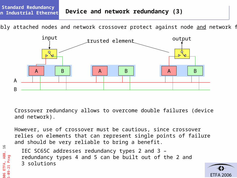
gStandard Redundancy in Industrial Ethernet Device and network redundancy (3)
A B
input output
A B A B
Crossover redundancy allows to overcome double failures (device and network).
However, use of crossover must be cautious, since crossover relies on elements that can represent single points of failure and should be very reliable to bring a benefit.
A
B
5) Doubly attached nodes and network crossover protect against node and network failure
trusted element
IEC SC65C addresses redundancy types 2 and 3 – redundancy types 4 and 5 can be built out of the 2 and 3 solutions
© 2
006
ET
FA
, AB
B, 1
7 20
06-0
9-21
Pra
gStandard Redundancy in Industrial Ethernet
1. Terms: availability and redundancy
2. Classification of requirements
3. Levels of device and network redundancy
4. Industrial Ethernet topologies
5. Industrial Ethernet stack and redundancy
6. IEC 62439 solutions
7. Conclusion

© 2
006
ET
FA
, AB
B, 1
8 20
06-0
9-21
Pra
gStandard Redundancy in Industrial Ethernet Ethernet-based automation networks (tree topology)
local area network
switch
trunk ports
inter-switch link
edge port
leaf link
edge links
inter-switch
link
edge port
end node
switchswitch
end node
end node
end node
end node
end node
end node
switch
end node
end node
switch
end node
end node
end node
end node
in principle no redundancy
© 2
006
ET
FA
, AB
B, 1
9 20
06-0
9-21
Pra
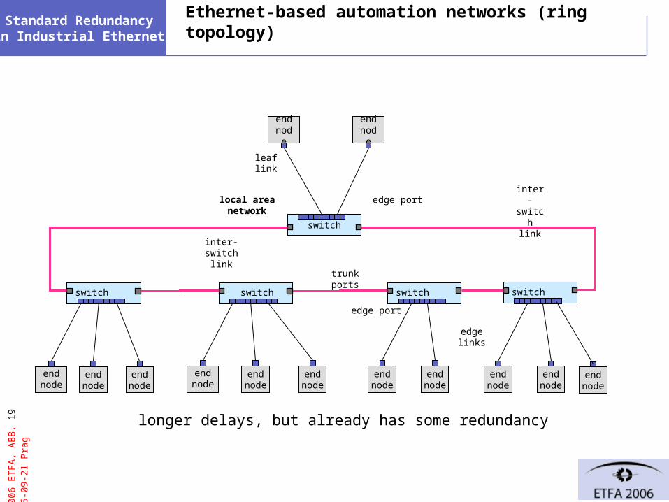
gStandard Redundancy in Industrial Ethernet Ethernet-based automation networks (ring topology)
local area network
switch
trunk ports
inter-switch link
edge port
leaf link
edge links
inter-switch
link
edge port
end node
switchswitch
end node
end node
end node
end node
end node
end node
switch
end node
end node
switch
end node
end node
end node
end node
longer delays, but already has some redundancy
© 2
006
ET
FA
, AB
B, 2
0 20
06-0
9-21
Pra
gStandard Redundancy in Industrial Ethernet
switch
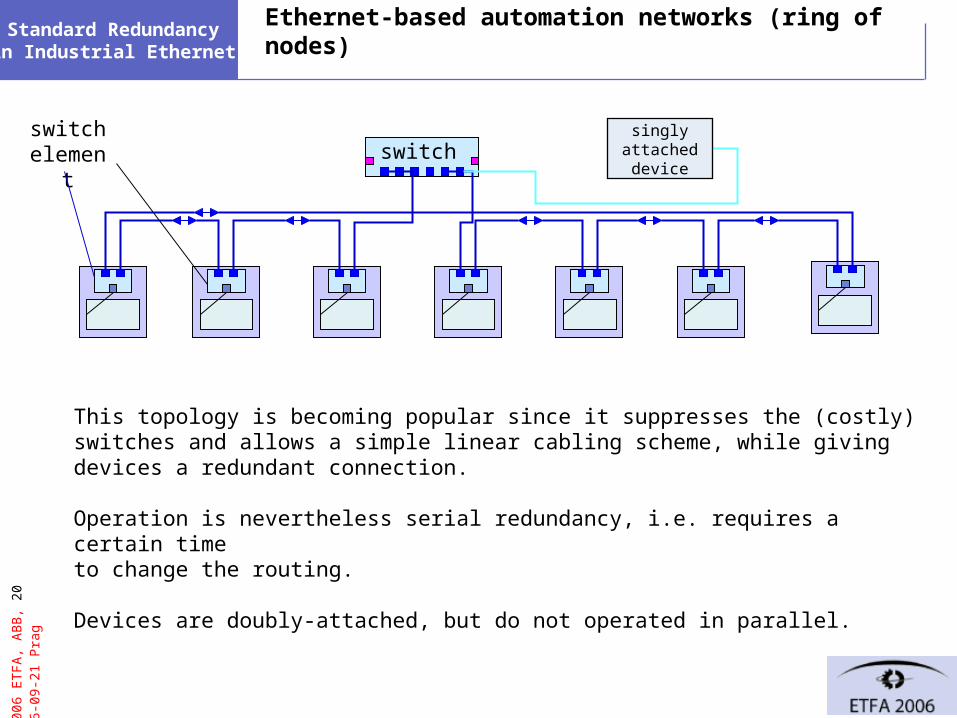
Ethernet-based automation networks (ring of nodes)
This topology is becoming popular since it suppresses the (costly) switches and allows a simple linear cabling scheme, while giving devices a redundant connection.
Operation is nevertheless serial redundancy, i.e. requires a certain timeto change the routing.
Devices are doubly-attached, but do not operated in parallel.
switch element
singlyattacheddevice
© 2
006
ET
FA
, AB
B, 2
1 20
06-0
9-21
Pra
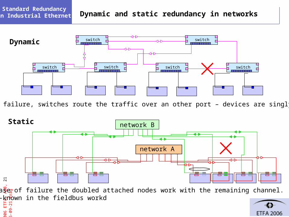
gStandard Redundancy in Industrial Ethernet Dynamic and static redundancy in networks
network BStatic
network A
switch
Dynamic
in case of failure, switches route the traffic over an other port – devices are singly attached
in case of failure the doubled attached nodes work with the remaining channel.Well-known in the fieldbus workd
switch switch switchswitch
switch switch

© 2
006
ET
FA
, AB
B, 2
2 20
06-0
9-21
Pra
gStandard Redundancy in Industrial Ethernet
1. Terms: availability and redundancy
2. Classification of requirements
3. Levels of device and network redundancy
4. Industrial Ethernet topologies
5. Industrial Ethernet stack and redundancy
6. IEC 62439 solutions
7. Conclusion

© 2
006
ET
FA
, AB
B, 2
3 20
06-0
9-21
Pra
gStandard Redundancy in Industrial Ethernet What makes Industrial Ethernet special
Most “Industrial Ethernet” uses the classical TCP-UDP-IP stack and in addition a layer 2 traffic for real-time data (but some use UDP) and a clock synchronization (IEEE 1588)
MAC/PHY Ethernet 802.3
TCP RFC 793UDP
IP
Client / Server services
PT=0800Link Layer
applicationapplicationapplication
SNTP,PTP,
(SNMP)
ARP
802.p1 / 802.1QPriority tag
PT=0806PTID=8100 802.2
spanningtree
(802.1d)
Hard Real-Time stack
void
Soft-Time stack
ICMP
Layer 7Publisher/Subscriber
Layer 2 Publisher /Subscriber
01
void
Therefore, Industrial Ethernet redundancy must operate at level 2

© 2
006
ET
FA
, AB
B, 2
4 20
06-0
9-21
Pra
gStandard Redundancy in Industrial Ethernet Communication stack and redundancy
The redundant Ethernet solutions distinguish themselves by:
- the OSI level at which switchover or selection is performed.
- whether they operate with dynamic or static redundancy
Industrial protocols operate both at network layer (IP) and at link layer (e.g. Real Time traffic, clock synchronization traffic),
Redundancy only at network level is not sufficient, it must be implemented at layer two to account for industrial Ethernets that use these layers.
Since standard methods handle effectively redundancy at the network layer ( TCP / IP), network level redundancy is separated from the device-level redundancy.
© 2
006
ET
FA
, AB
B, 2
5 20
06-0
9-21
Pra
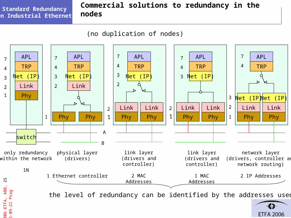
gStandard Redundancy in Industrial Ethernet Commercial solutions to redundancy in the nodes
physical layer(drivers)
1 Ethernet controller
link layer(drivers and controller)
2 MAC Addresses
network layer(drivers, controller and
network routing)
2 IP Addresses
only redundancywithin the network
1N
1
2
3
4
7
Net (IP)
Link
Phy
TRP
Link
Phy Phy
TRP
Net (IP)
Link
Phy Phy
Link
TRP
Net (IP)
Link
Phy Phy
Link
Net (IP)
Net (IP)
APL APL APL
TRP
APL
2
3
4
7
2
3
4
7
1
2
3
4
7
1 1 1
TRP
Net (IP)
Link
Phy Phy
Link
APL
2
3
4
7
link layer(drivers and controller)
1 MAC Addresses
A
Bswitch
1
2
(no duplication of nodes)
the level of redundancy can be identified by the addresses used
© 2
006
ET
FA
, AB
B, 2
6 20
06-0
9-21
Pra
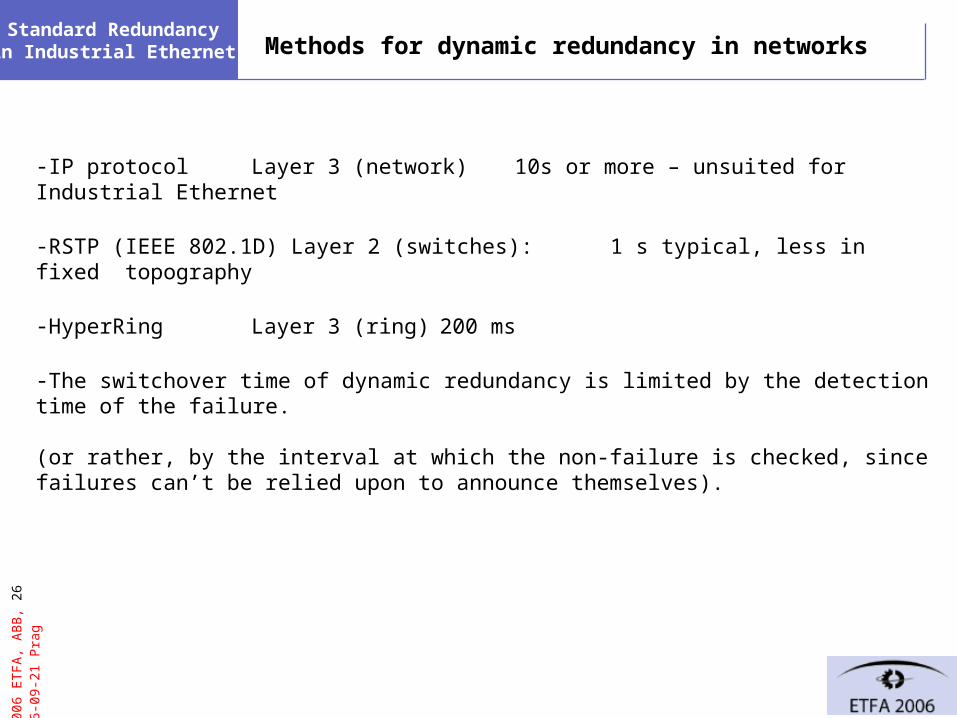
gStandard Redundancy in Industrial Ethernet Methods for dynamic redundancy in networks
-IP protocol Layer 3 (network) 10s or more – unsuited for Industrial Ethernet
-RSTP (IEEE 802.1D) Layer 2 (switches): 1 s typical, less in fixed topography
-HyperRing Layer 3 (ring) 200 ms
-The switchover time of dynamic redundancy is limited by the detection time of the failure.
(or rather, by the interval at which the non-failure is checked, since failures can’t be relied upon to announce themselves).

© 2
006
ET
FA
, AB
B, 2
7 20
06-0
9-21
Pra
gStandard Redundancy in Industrial Ethernet
1. Terms: availability and redundancy
2. Classification of requirements
3. Levels of device and network redundancy
4. Industrial Ethernet topologies
5. Industrial Ethernet stack and redundancy
6. IEC 62439 solutions
7. Conclusion
© 2
006
ET
FA
, AB
B, 2
8 20
06-0
9-21
Pra
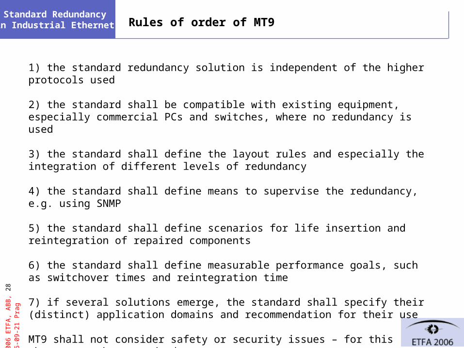
gStandard Redundancy in Industrial Ethernet Rules of order of MT9
1) the standard redundancy solution is independent of the higher protocols used 2) the standard shall be compatible with existing equipment, especially commercial PCs and switches, where no redundancy is used
3) the standard shall define the layout rules and especially the integration of different levels of redundancy
4) the standard shall define means to supervise the redundancy, e.g. using SNMP
5) the standard shall define scenarios for life insertion and reintegration of repaired components
6) the standard shall define measurable performance goals, such as switchover times and reintegration time
7) if several solutions emerge, the standard shall specify their (distinct) application domains and recommendation for their use
MT9 shall not consider safety or security issues – for this there are other standards.
© 2
006
ET
FA
, AB
B, 2
9 20
06-0
9-21
Pra
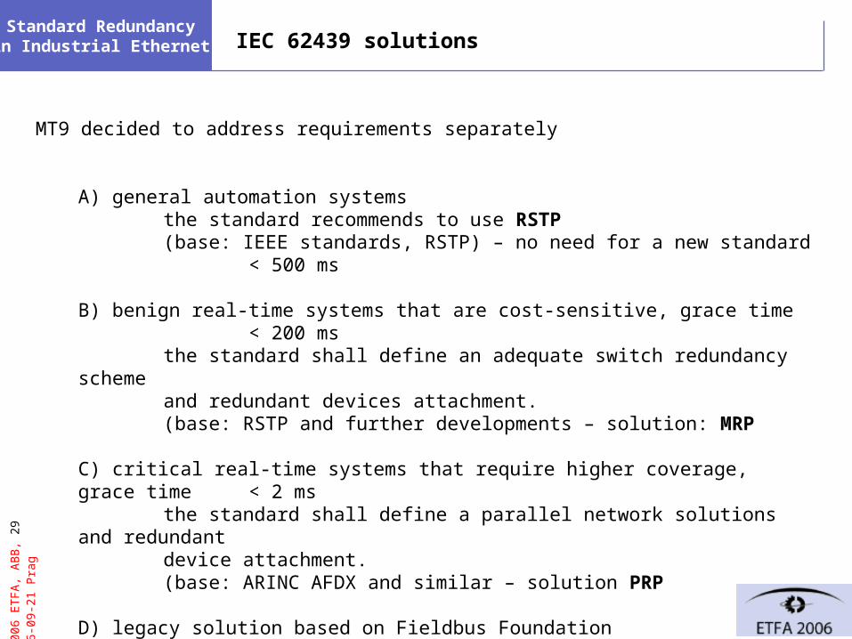
gStandard Redundancy in Industrial Ethernet IEC 62439 solutions
MT9 decided to address requirements separately
A) general automation systemsthe standard recommends to use RSTP(base: IEEE standards, RSTP) – no need for a new standard < 500
ms
B) benign real-time systems that are cost-sensitive, grace time < 200 ms
the standard shall define an adequate switch redundancy schemeand redundant devices attachment.
(base: RSTP and further developments – solution: MRP
C) critical real-time systems that require higher coverage, grace time < 2 ms the standard shall define a parallel network solutions and redundantdevice attachment.(base: ARINC AFDX and similar – solution PRP
D) legacy solution based on Fieldbus Foundation
© 2
006
ET
FA
, AB
B, 3
0 20
06-0
9-21
Pra
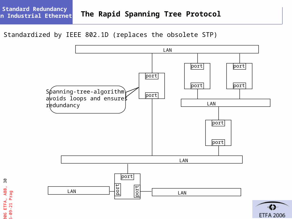
gStandard Redundancy in Industrial Ethernet The Rapid Spanning Tree Protocol
Standardized by IEEE 802.1D (replaces the obsolete STP)
port
port
LAN
port
port
port
port
LAN
port
port
LAN
LANLAN po
rt
port
po
rt
Spanning-tree-algorithmavoids loops and ensuresredundancy
© 2
006
ET
FA
, AB
B, 3
1 20
06-0
9-21
Pra
gStandard Redundancy in Industrial Ethernet RSTP performance
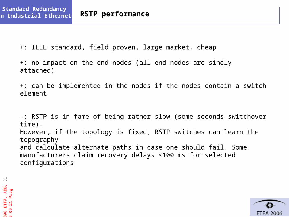
+: IEEE standard, field proven, large market, cheap
+: no impact on the end nodes (all end nodes are singly attached)
+: can be implemented in the nodes if the nodes contain a switch element
-: RSTP is in fame of being rather slow (some seconds switchover time). However, if the topology is fixed, RSTP switches can learn the topographyand calculate alternate paths in case one should fail. Some manufacturers claim recovery delays <100 ms for selected configurations
© 2
006
ET
FA
, AB
B, 3
2 20
06-0
9-21
Pra
gStandard Redundancy in Industrial Ethernet MRP (based on Siemens-Hirschmann hyperring)
intact ring MRC
end node
end node
end node
… end node
end node
end node
…end node
end node
end node
…
MRM
end node
end node
end node
end node
end node
end node
MRCMRCMRC
MRC
end node
end node
end node
…end node
end node
end node
…end node
end node
end node
…
MRM
end node
end node
end node
end node
end node
end node
MRCMRCMRC
broken ring
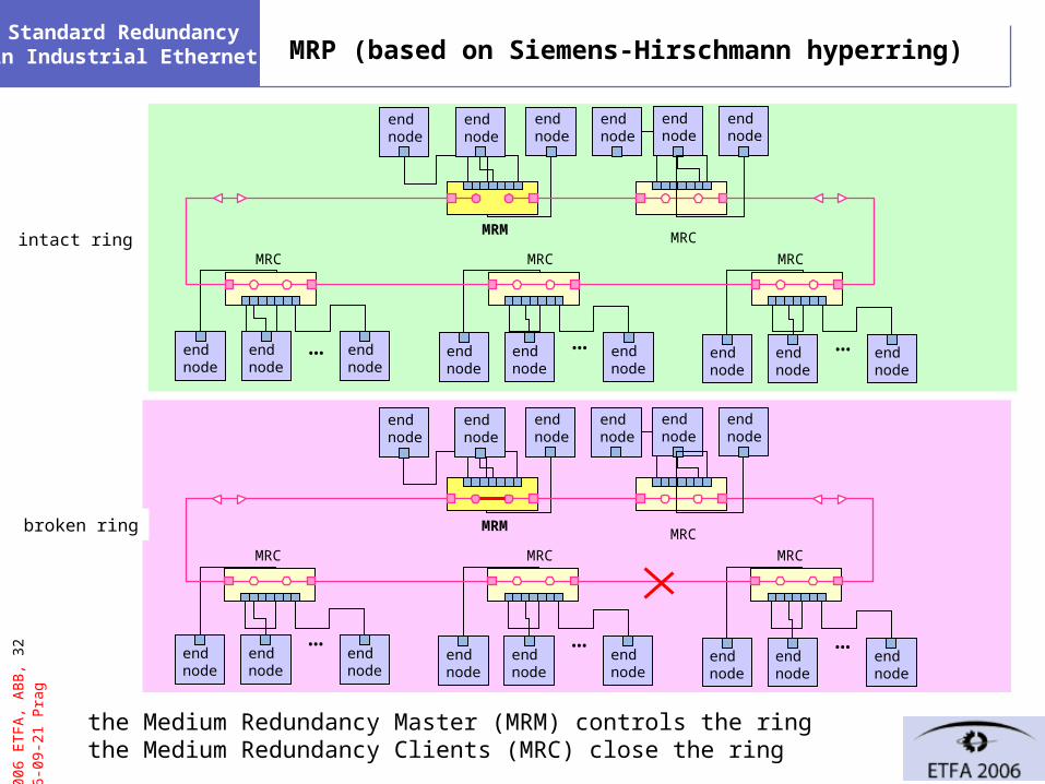
the Medium Redundancy Master (MRM) controls the ringthe Medium Redundancy Clients (MRC) close the ring
© 2
006
ET
FA
, AB
B, 3
3 20
06-0
9-21
Pra
gStandard Redundancy in Industrial Ethernet MRP
The MRM checks the integrity of the ring by sending in both direction test frames.
These test frames are forwarded by all intact switches and inter-switch links.
If the MRM does not receive its own frames over its other interface, it closes the ringat its location, reestablishing traffic.
Supervision frames allows to locate the source of the trouble.
+: fast switchover (< 200ms worst case)
+: no impact on the nodes
+: no increase in network infrastructure.
-: MRP switches are not compatible with RSTP switches, limited market
-: limited to ring topology
© 2
006
ET
FA
, AB
B, 3
4 20
06-0
9-21
Pra
gStandard Redundancy in Industrial Ethernet Fieldbus Redundancy Protocol
trunk link
branch port
trunk link
switch
end node
switch
local area network (tree) B
branch port
leaf link
end node
leaf link
switchswitch
trunk ports
branch port
switch
end node
leaf link
switch
trunk inter-LAN link
end node
end node
end node
local area network (tree) A
© 2
006
ET
FA
, AB
B, 3
5 20
06-0
9-21
Pra
gStandard Redundancy in Industrial Ethernet FRP
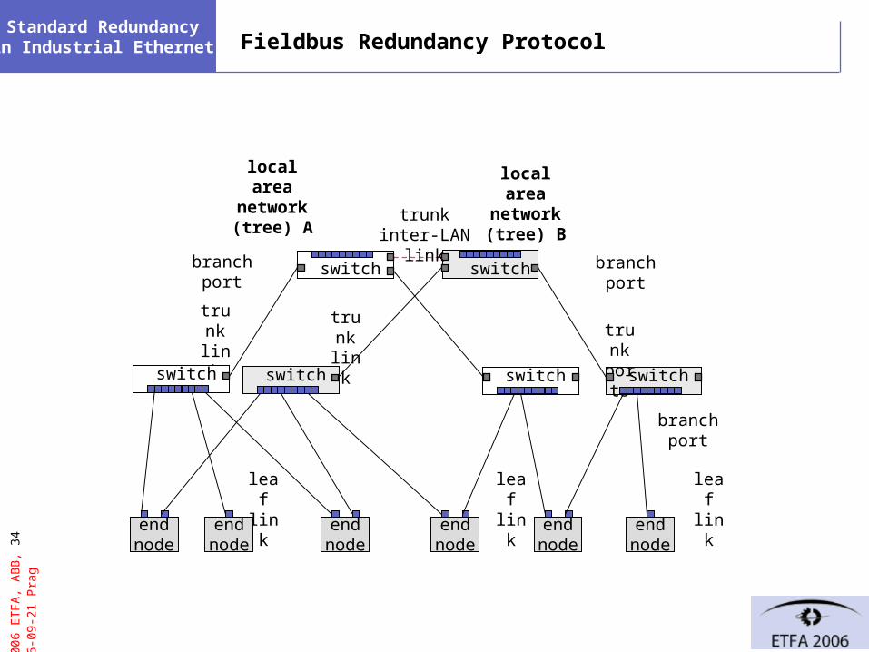
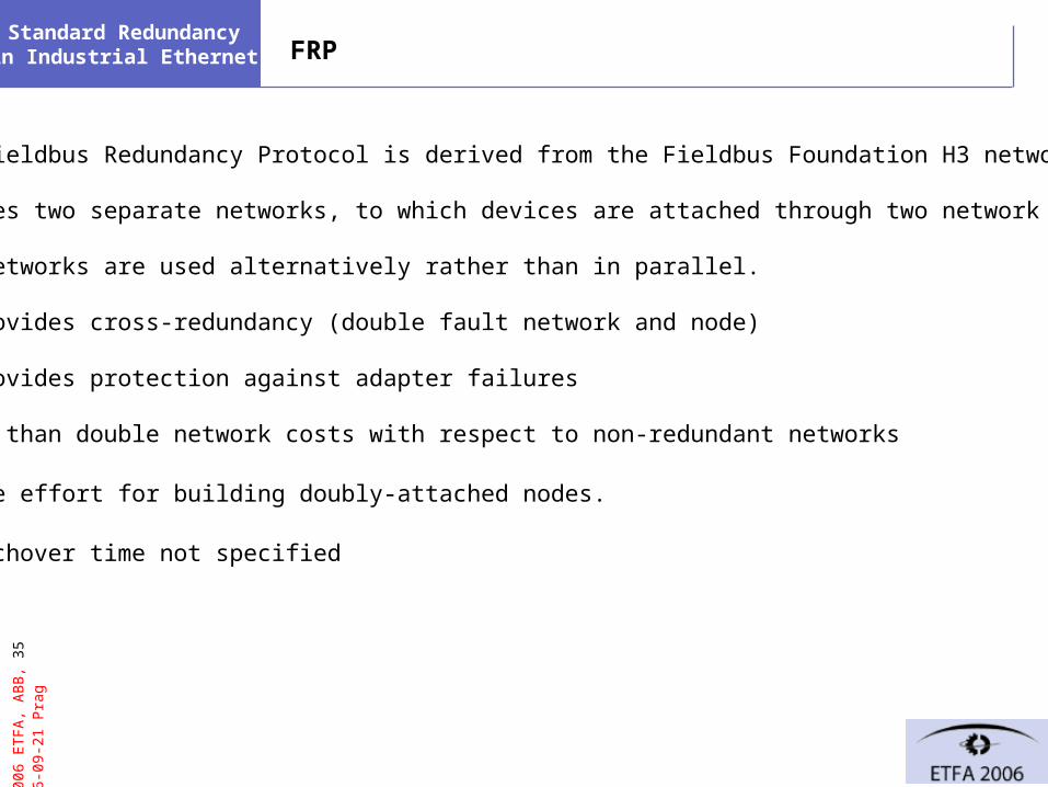
The Fieldbus Redundancy Protocol is derived from the Fieldbus Foundation H3 network.
It uses two separate networks, to which devices are attached through two network adapters.
The networks are used alternatively rather than in parallel.
+: provides cross-redundancy (double fault network and node)
+: provides protection against adapter failures
-more than double network costs with respect to non-redundant networks
-large effort for building doubly-attached nodes.
-switchover time not specified

© 2
006
ET
FA
, AB
B, 3
6 20
06-0
9-21
Pra
gStandard Redundancy in Industrial Ethernet Parallel Redundancy Protocol
A
B
send
Tx RxTx Tx RxTx Rx
receive
send on both lines: each frame is send on both A and B lines, frames over A and B have different transmission delays (or may not arrive at all)
receive on both lines: the stack receives both frames from both lines treated as equal, a "merge layer" between the link and the network layer suppresses duplicates.
network layer
transport layer
send
Rx
receive
bus controller
layer redundancymanager
transceivers
A B A B
sameinterface
publisher/subscriber network layer
transport layerpublisher/subscriber
upper layers
lane A
lane B
© 2
006
ET
FA
, AB
B, 3
7 20
06-0
9-21
Pra
gStandard Redundancy in Industrial Ethernet PRP layout examples
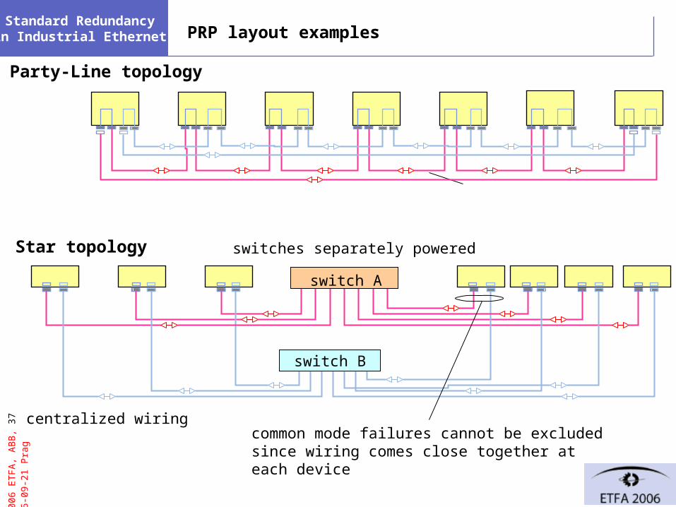
centralized wiring
switch B
Star topology
Party-Line topology
switch A
common mode failures cannot be excluded since wiring comes close together at each device
switches separately powered
© 2
006
ET
FA
, AB
B, 3
8 20
06-0
9-21
Pra
gStandard Redundancy in Industrial Ethernet PRP suppressing duplicates
timedestination source LLC FCSLPDUpreamble sizesequence line
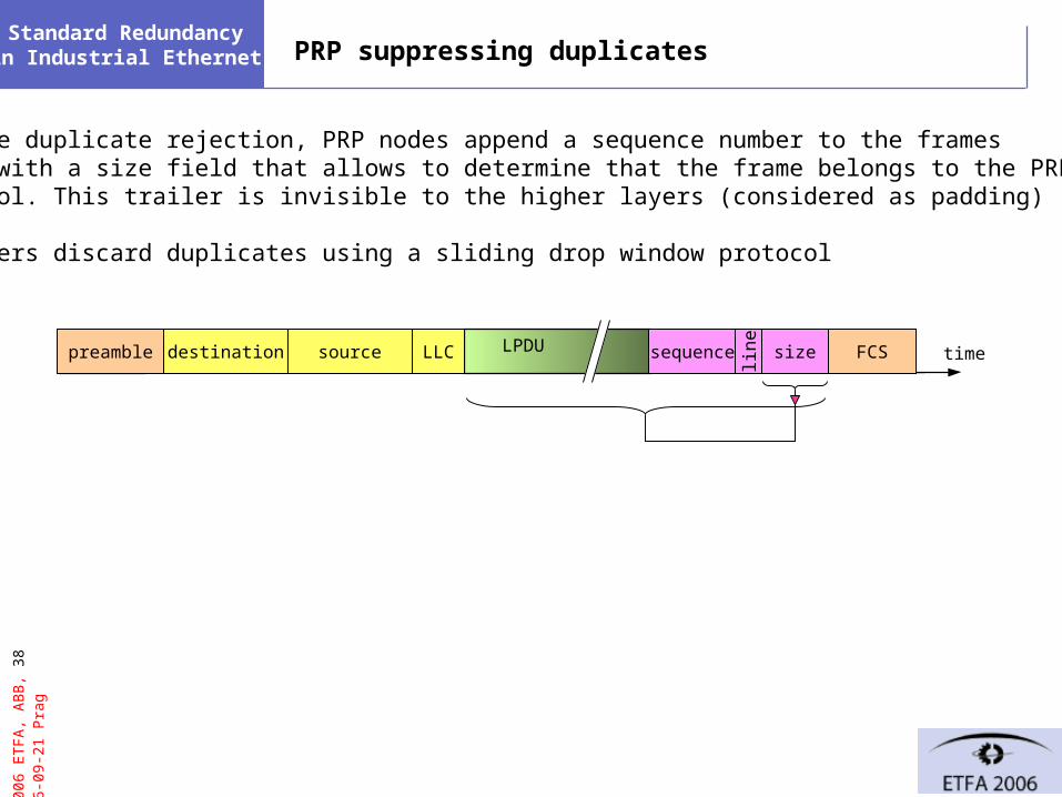
To ease duplicate rejection, PRP nodes append a sequence number to the framesalong with a size field that allows to determine that the frame belongs to the PRPprotocol. This trailer is invisible to the higher layers (considered as padding)
Receivers discard duplicates using a sliding drop window protocol
© 2
006
ET
FA
, AB
B, 3
9 20
06-0
9-21
Pra
gStandard Redundancy in Industrial Ethernet PRP
+ PRP allows bumpless switchover, no frames are lost
+ During normal operation, PRP reduces the loss rate
+ PRP checks the presence of nodes by periodical supervision frames that also indicate which nodes participate in the protocol and which not
-: double network costs
-: doubly attached devices are costly to build
-: frame size must be limited to prevent frames from becoming longer than the IEEE 802.3-maximum size (but most switches and Ethernet controllers accept frames up to 1536 octets)

© 2
006
ET
FA
, AB
B, 4
0 20
06-0
9-21
Pra
gStandard Redundancy in Industrial Ethernet
1. Terms: availability and redundancy
2. Classification of requirements
3. Levels of device and network redundancy
4. Industrial Ethernet topologies
5. Industrial Ethernet stack and redundancy
6. IEC 62439 solutions
7. Conclusion

© 2
006
ET
FA
, AB
B, 4
1 20
06-0
9-21
Pra
gStandard Redundancy in Industrial Ethernet Conclusion
IEC 62439 satisfies the needs of the Industrial Ethernets belonging to the IEC 61784suite with three (four) solutions:
-RSTP is sufficient for many applications–with improvements for fixed configuration
-MRP: a ring-based protocol for demanding automation networks and singly attached nodes
-PRP: a parallel network protocol for critical applications requiring doubly attached nodes.
-FRP, especially in conjunction with Fieldbus Foundation, requiring doubly attached nodes.


© 2
006
ET
FA
, AB
B, 4
3 20
06-0
9-21
Pra
gStandard Redundancy in Industrial Ethernet Consider redundancy failure
upfirst failure(recovered)
successfulrepair
2nd failure or unsuccessful repair
not recovered first failure
plant recovery (not considered here)
λ + λr
λ (1-c)
λc μ
ρ
2nd failure or unsuccessful repair
successfuldetection and repair
upimpaired
upintact down
upredundancy
loss


![Performance of a full-hardware PTP implementation 3 ......2 [5], by using IEC 62439-3 [2] as explained IEC 62439-3 consists of two redundanc zero switchover delay, PRP (Parallel Redu](https://img.pdfslide.us/doc/110x75/6131896f1ecc51586944cc45/performance-of-a-full-hardware-ptp-implementation-3-2-5-by-using-iec.jpg)