Embed Size (px)
Citation preview
2005 Pearson Education South Asia Pte Ltd
TUTORIAL-4: FAILURE THEORIES
1
THEORIES OF FAILURE
Failure in a ductile material is specified by the initiation of yielding.
Failure in a brittle material is specified by fracture.
THEORIES OF FAILURE FOR DUCTILE MATERIALS
Maximum Shear Stress Theory (Tresca Yield Criterion)
The most common cause of yielding of a ductile material such as steel is slipping, which occurs along the contact planes of randomly ordered crystals that make up the material.
This slipping is due to shear stress : 2
minmaxabsmax
2005 Pearson Education South Asia Pte Ltd
TUTORIAL-4: FAILURE THEORIES
2
THEORIES OF FAILURE
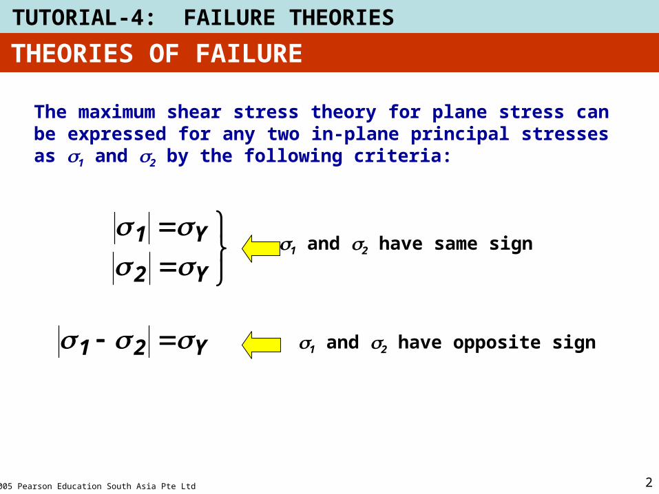
The maximum shear stress theory for plane stress can be expressed for any two in-plane principal stresses as s1 and s2 by the following criteria:
Y2
Y1
s1 and s2 have same sign
Y21 s1 and s2 have opposite sign
2005 Pearson Education South Asia Pte Ltd
TUTORIAL-4: FAILURE THEORIES
3
THEORIES OF FAILURE
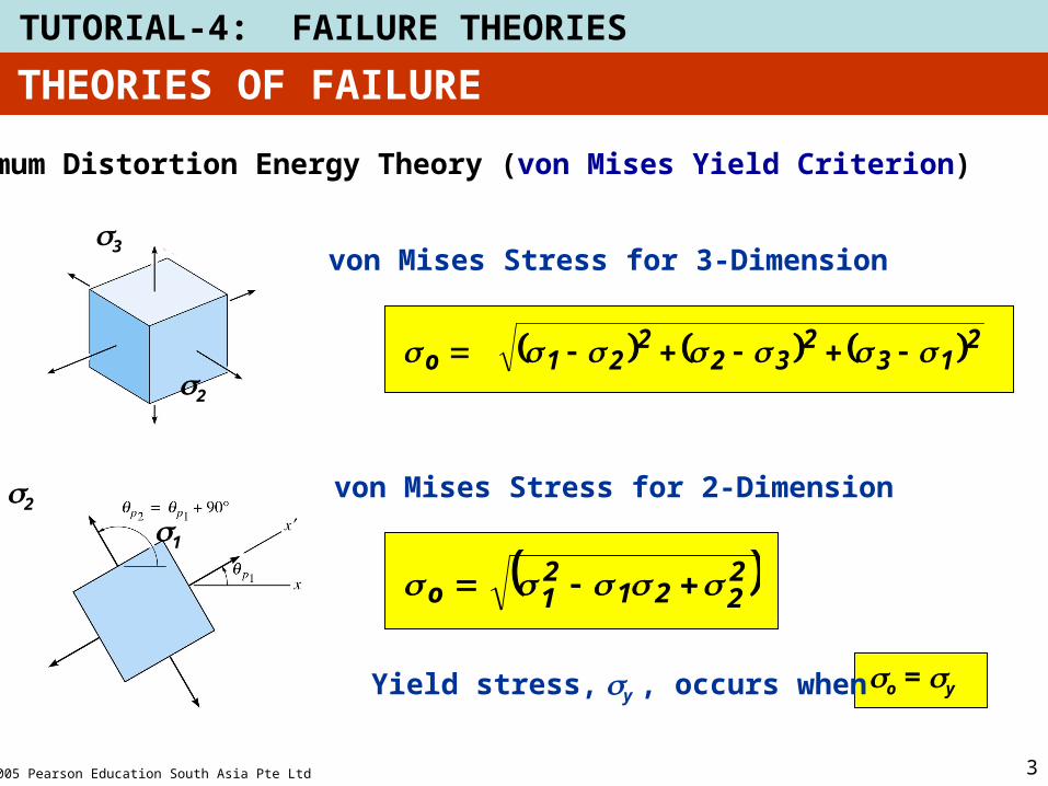
Maximum Distortion Energy Theory (von Mises Yield Criterion)
s1
s3
s2
von Mises Stress for 3-Dimension
2132
322
21o
s2
s1
von Mises Stress for 2-Dimension
2221
21o
Yield stress, sy , occurs when so = sy
2005 Pearson Education South Asia Pte Ltd
TUTORIAL-4: FAILURE THEORIES
4
THEORIES OF FAILURE
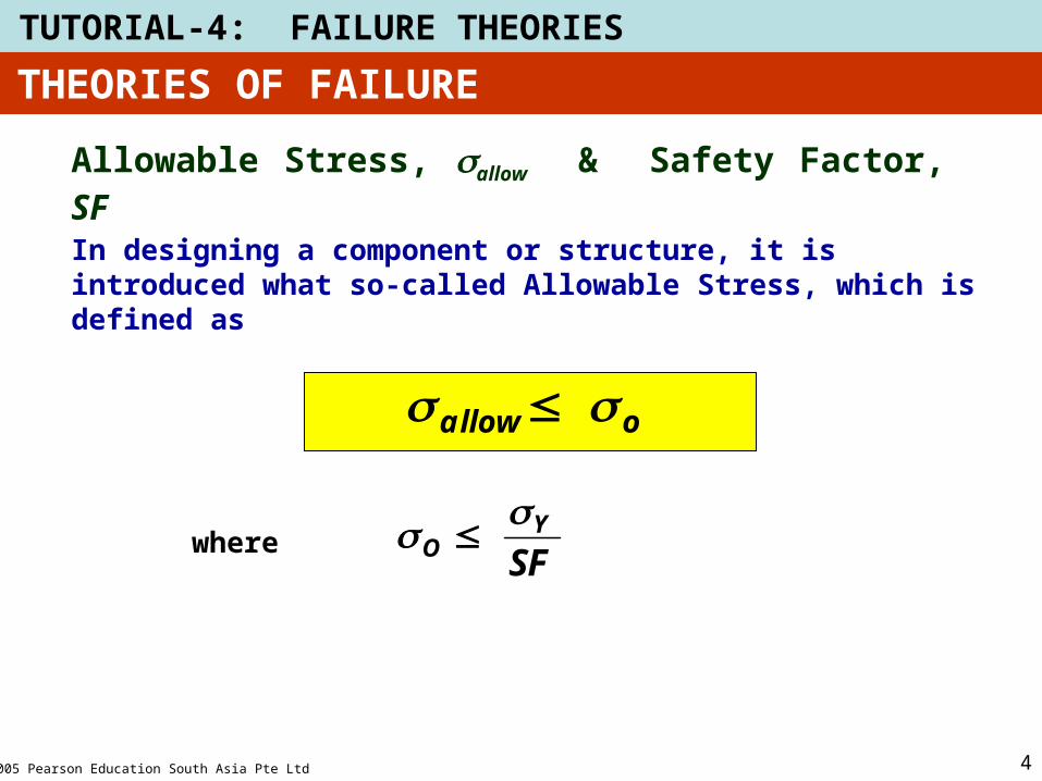
Allowable Stress, sallow & Safety Factor, SF
In designing a component or structure, it is introduced what so-called Allowable Stress, which is defined as
oallow
SFY
O where
2005 Pearson Education South Asia Pte Ltd
TUTORIAL-4: FAILURE THEORIES
5
THEORIES OF FAILURE
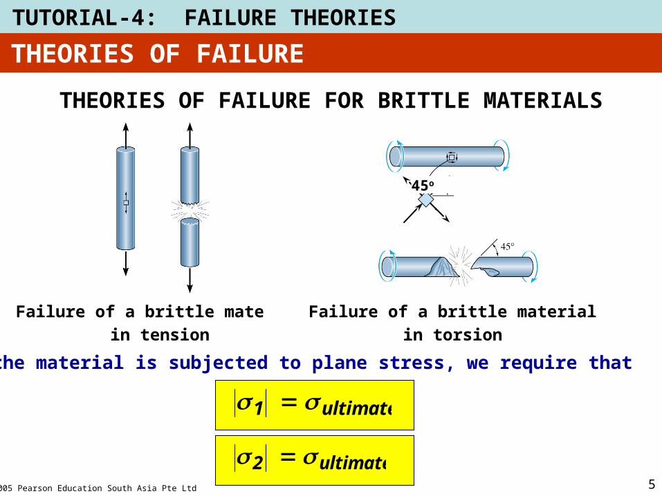
THEORIES OF FAILURE FOR BRITTLE MATERIALS
Failure of a brittle material
in tension
45o
Failure of a brittle material
in torsion
If the material is subjected to plane stress, we require that
ultimate1
ultimate2
2005 Pearson Education South Asia Pte Ltd
TUTORIAL-4: FAILURE THEORIES
6
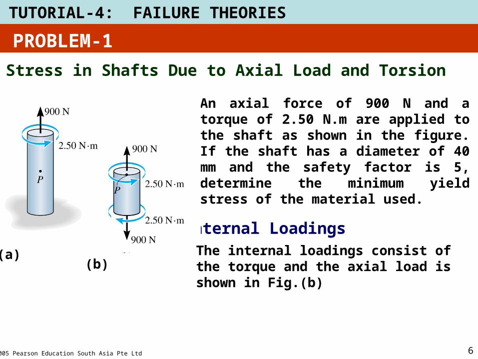
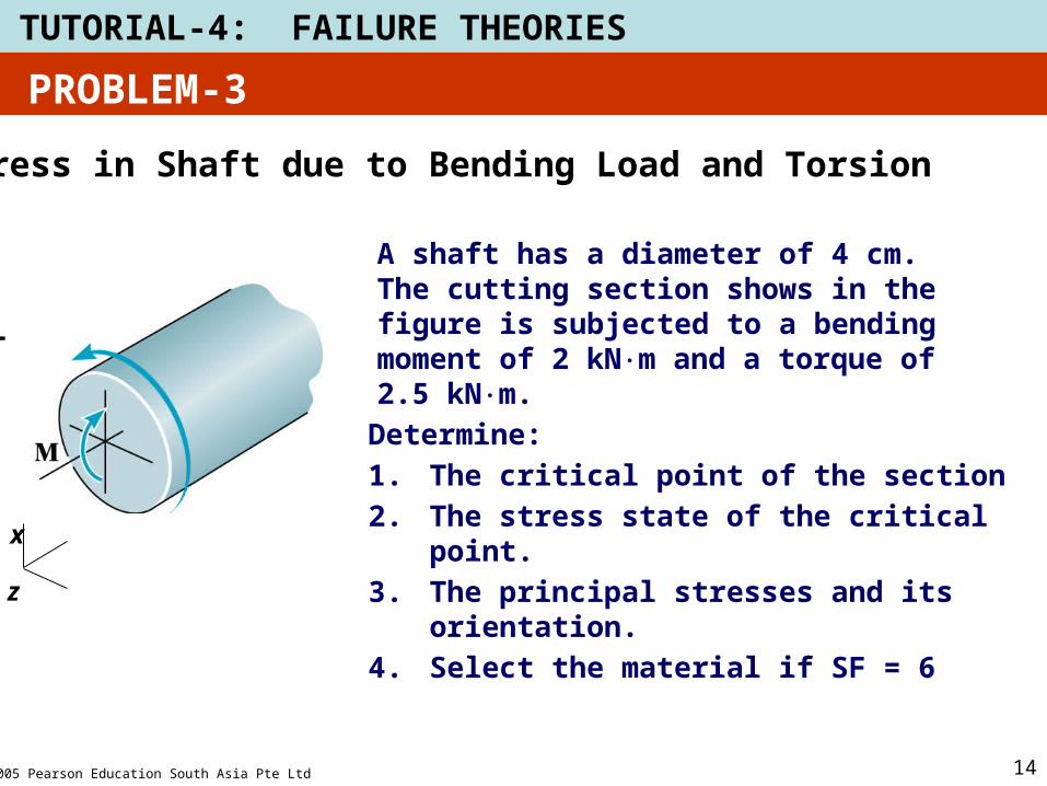
Stress in Shafts Due to Axial Load and Torsion
An axial force of 900 N and a torque of 2.50 N.m are applied to the shaft as shown in the figure. If the shaft has a diameter of 40 mm and the safety factor is 5, determine the minimum yield stress of the material used.
Internal Loadings
(a)(a)(b)
PROBLEM-1
The internal loadings consist of the torque and the axial load is shown in Fig.(b)
2005 Pearson Education South Asia Pte Ltd
TUTORIAL-4: FAILURE THEORIES
7
(a)(b)
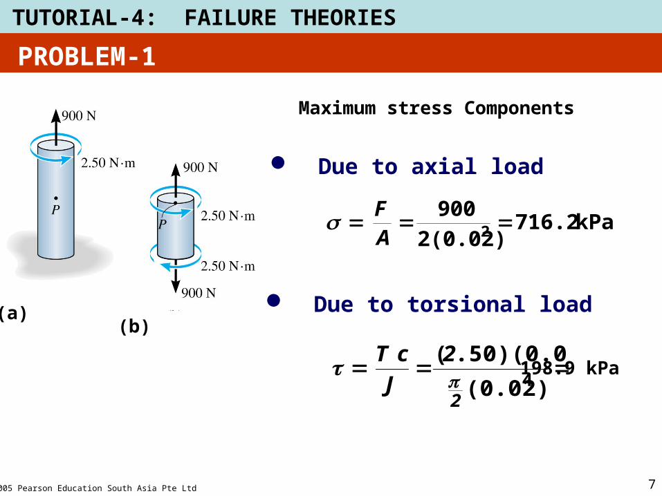
Maximum stress Components
Due to torsional load
4(0.02)
.50)(0.02)(
2
2
J
cT
198.9 kPa
Due to axial load
kPa716.22(0.02)
9002
AF
PROBLEM-1
2005 Pearson Education South Asia Pte Ltd
TUTORIAL-4: FAILURE THEORIES
8
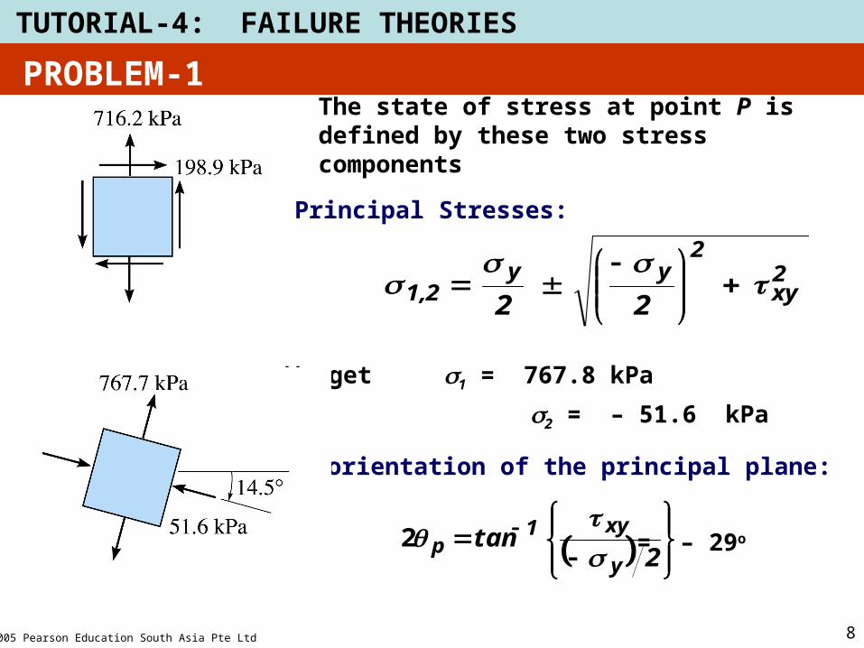
The state of stress at point P is defined by these two stress components
Principal Stresses:
2xy
2yy
2,1 22
We get s1 = 767.8 kPa
s2 = – 51.6 kPa
The orientation of the principal plane:
2tan
y
xy1p
2 = – 29o
PROBLEM-1
2005 Pearson Education South Asia Pte Ltd
TUTORIAL-4: FAILURE THEORIES
9
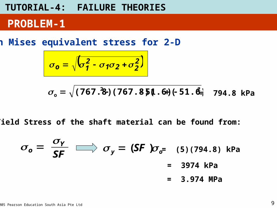
von Mises equivalent stress for 2-D
2221
21o
22o 51.6)(51.6)(767.8)((767.8) = 794.8 kPa
PROBLEM-1
Yield Stress of the shaft material can be found from:
SFY
o
oy SF )( = (5)(794.8) kPa
= 3974 kPa
= 3.974 MPa
2005 Pearson Education South Asia Pte Ltd
TUTORIAL-4: FAILURE THEORIES
10
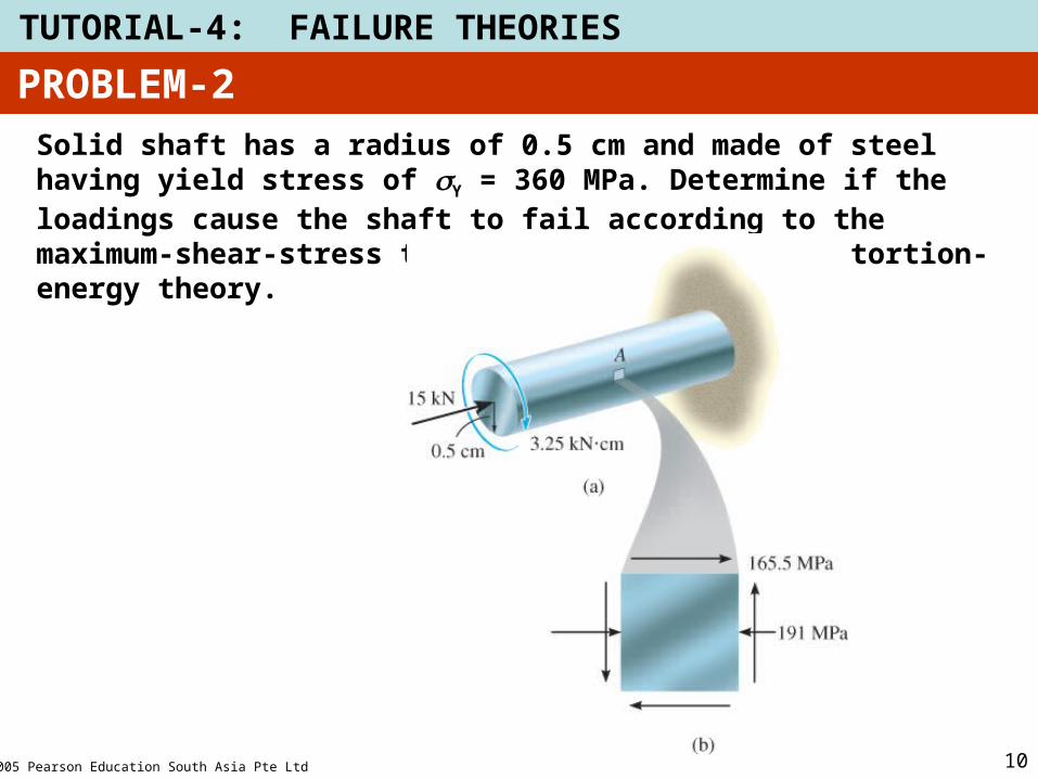
Solid shaft has a radius of 0.5 cm and made of steel having yield stress of Y = 360 MPa. Determine if the loadings cause the shaft to fail according to the maximum-shear-stress theory and the maximum-distortion-energy theory.
PROBLEM-2
2005 Pearson Education South Asia Pte Ltd
TUTORIAL-4: FAILURE THEORIES
11
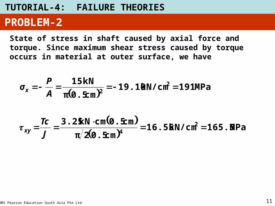
State of stress in shaft caused by axial force and torque. Since maximum shear stress caused by torque occurs in material at outer surface, we have
MPa165.5kN/cm16.55cm0.52π
cm0.5cmkN3.25
MPa191kN/cm19.10cm0.5π
kN15
24
22
J
Tc
A
Pσ
xy
x
PROBLEM-2
2005 Pearson Education South Asia Pte Ltd
TUTORIAL-4: FAILURE THEORIES
12
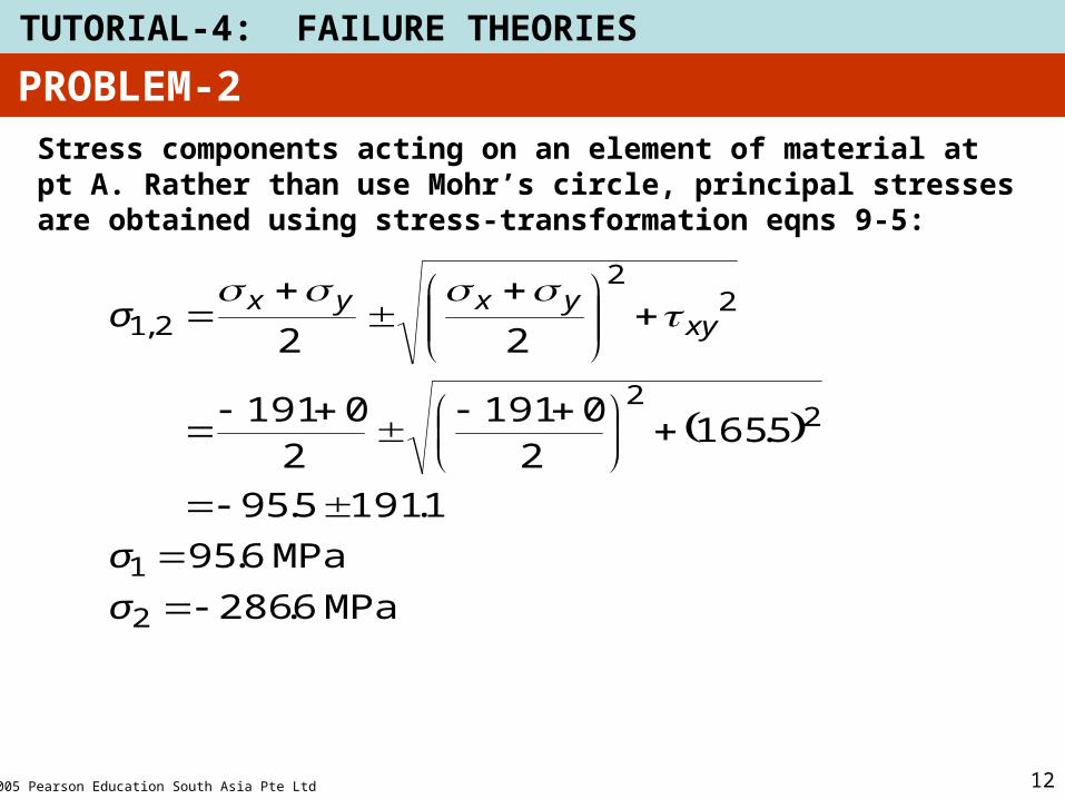
Stress components acting on an element of material at pt A. Rather than use Mohr’s circle, principal stresses are obtained using stress-transformation eqns 9-5:
MPa6.286
MPa6.95
1.1915.95
5.16520191
20191
22
2
1
22
22
2,1
σ
σ
σ xyyxyx
PROBLEM-2
2005 Pearson Education South Asia Pte Ltd
TUTORIAL-4: FAILURE THEORIES
13
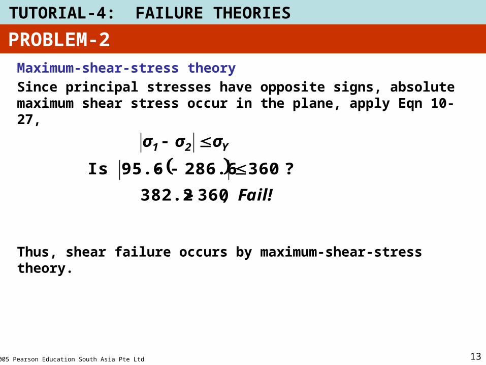
Maximum-shear-stress theory
Since principal stresses have opposite signs, absolute maximum shear stress occur in the plane, apply Eqn 10-27,
Thus, shear failure occurs by maximum-shear-stress theory.
Fail!,
σσσ Y21
360382.2
?360286.695.6Is
PROBLEM-2
2005 Pearson Education South Asia Pte Ltd
TUTORIAL-4: FAILURE THEORIES
14
Stress in Shaft due to Bending Load and Torsion
T
xy
z
A shaft has a diameter of 4 cm. The cutting section shows in the figure is subjected to a bending moment of 2 kNm and a torque of 2.5 kNm.
Determine:
1. The critical point of the section
2. The stress state of the critical point.
3. The principal stresses and its orientation.
4. Select the material if SF = 6
PROBLEM-3
2005 Pearson Education South Asia Pte Ltd
TUTORIAL-4: FAILURE THEORIES
15
T
xy
z
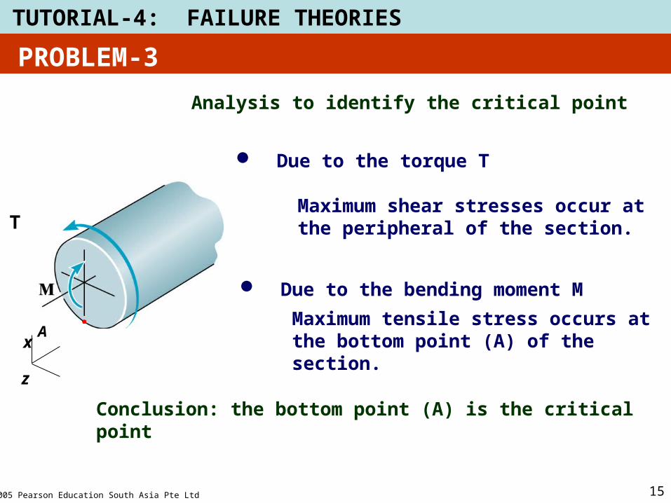
Analysis to identify the critical point
Maximum shear stresses occur at the peripheral of the section.
Due to the torque T
Due to the bending moment M
Maximum tensile stress occurs at the bottom point (A) of the section.
Conclusion: the bottom point (A) is the critical point
A
PROBLEM-3
2005 Pearson Education South Asia Pte Ltd
TUTORIAL-4: FAILURE THEORIES
16
T
xy
z
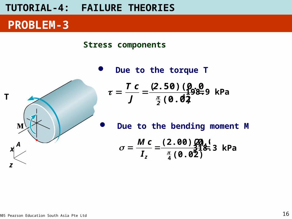
Stress components
Due to the torque T
Due to the bending moment M
A
198.9 kPa)(0.02
.50)(0.02)(4
2
2
J
cT
318.3 kPa4
4 (0.02)
2)(2.00)(0.0
zI
cM
PROBLEM-3
2005 Pearson Education South Asia Pte Ltd
TUTORIAL-4: FAILURE THEORIES
17
318.3 kPa
198.9 kPa
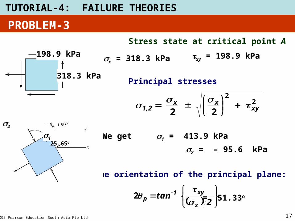
Stress state at critical point A
sx = 318.3 kPa txy = 198.9 kPa
Principal stresses
22
22 xyxx
1,2
We get s1 = 413.9 kPa
s2 = – 95.6 kPa
The orientation of the principal plane:
2tan
x
xy1
p2 = 51.33o
25.65o
s1
s2
PROBLEM-3
2005 Pearson Education South Asia Pte Ltd
TUTORIAL-4: FAILURE THEORIES
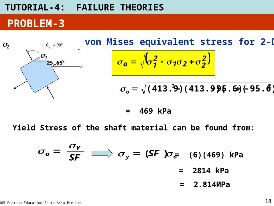
18
25.65o
s1
s2von Mises equivalent stress for 2-D
2221
21o
22o 95.6)(95.6)(413.9)((413.9)
= 469 kPa
PROBLEM-3
Yield Stress of the shaft material can be found from:
SFY
o
oy SF )( = (6)(469) kPa
= 2814 kPa
= 2.814MPa
2005 Pearson Education South Asia Pte Ltd
TUTORIAL-4: FAILURE THEORIES
19
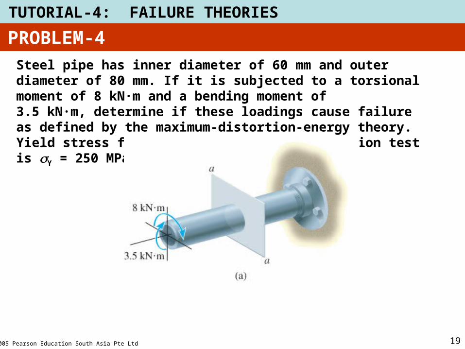
PROBLEM-4
Steel pipe has inner diameter of 60 mm and outer diameter of 80 mm. If it is subjected to a torsional moment of 8 kN·m and a bending moment of
3.5 kN·m, determine if these loadings cause failure as defined by the maximum-distortion-energy theory. Yield stress for the steel found from a tension test is Y = 250 MPa.
2005 Pearson Education South Asia Pte Ltd
TUTORIAL-4: FAILURE THEORIES
20
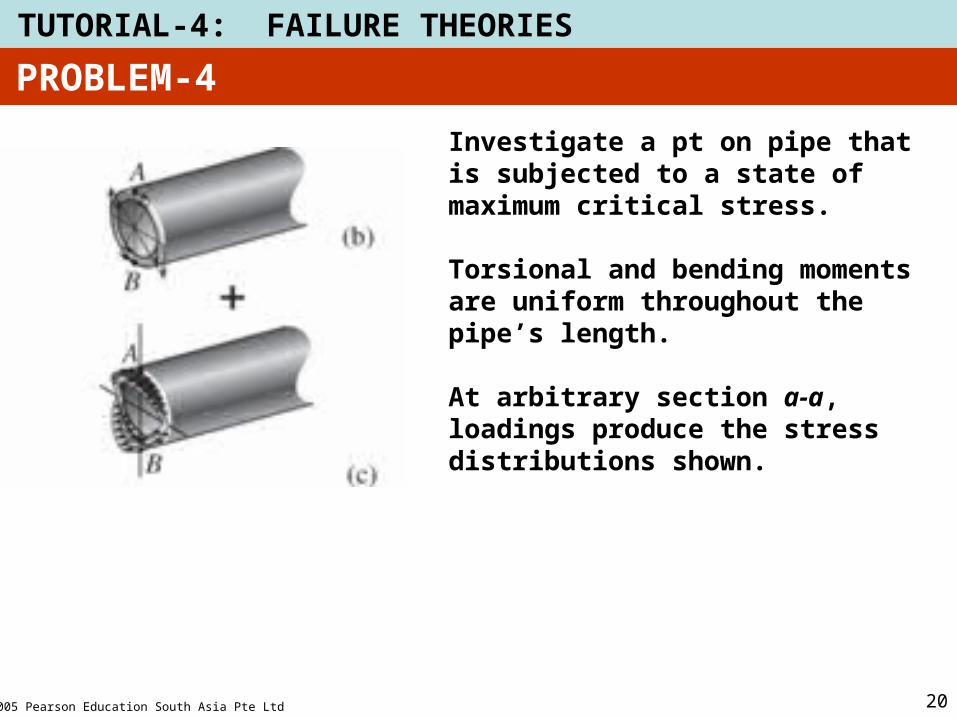
Investigate a pt on pipe that is subjected to a state of maximum critical stress.
Torsional and bending moments are uniform throughout the pipe’s length.
At arbitrary section a-a, loadings produce the stress distributions shown.
PROBLEM-4
2005 Pearson Education South Asia Pte Ltd
TUTORIAL-4: FAILURE THEORIES
21
PROBLEM-4

2005 Pearson Education South Asia Pte Ltd
TUTORIAL-4: FAILURE THEORIES
22
PROBLEM-4

2005 Pearson Education South Asia Pte Ltd
TUTORIAL-4: FAILURE THEORIES
23
PROBLEM-4
2005 Pearson Education South Asia Pte Ltd
TUTORIAL-4: FAILURE THEORIES
24
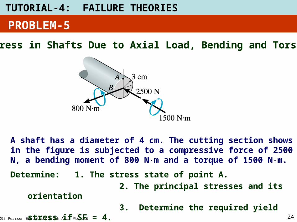
Stress in Shafts Due to Axial Load, Bending and Torsion
A shaft has a diameter of 4 cm. The cutting section shows in the figure is subjected to a compressive force of 2500 N, a bending moment of 800 Nm and a torque of 1500 Nm.
Determine: 1. The stress state of point A.
2. The principal stresses and its orientation
3. Determine the required yield stress if SF = 4.
PROBLEM-5
2005 Pearson Education South Asia Pte Ltd
TUTORIAL-4: FAILURE THEORIES
25
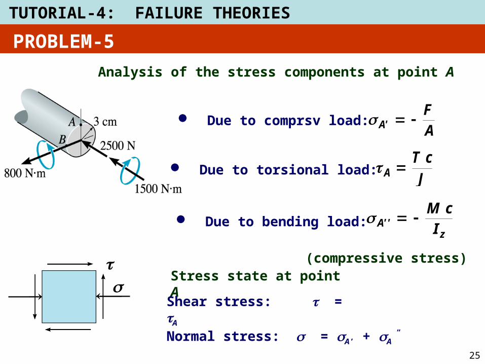
Analysis of the stress components at point A
Due to comprsv load:
Due to torsional load:JcT
A
AF
A'
Due to bending load:z
'A' IcM
(compressive stress)
Stress state at point A
Shear stress: t = tA
Normal stress: s = sA’ + sA”
ts
PROBLEM-5