Embed Size (px)
Citation preview

بسم هللا الرحمن الرحيم
Dimensioning
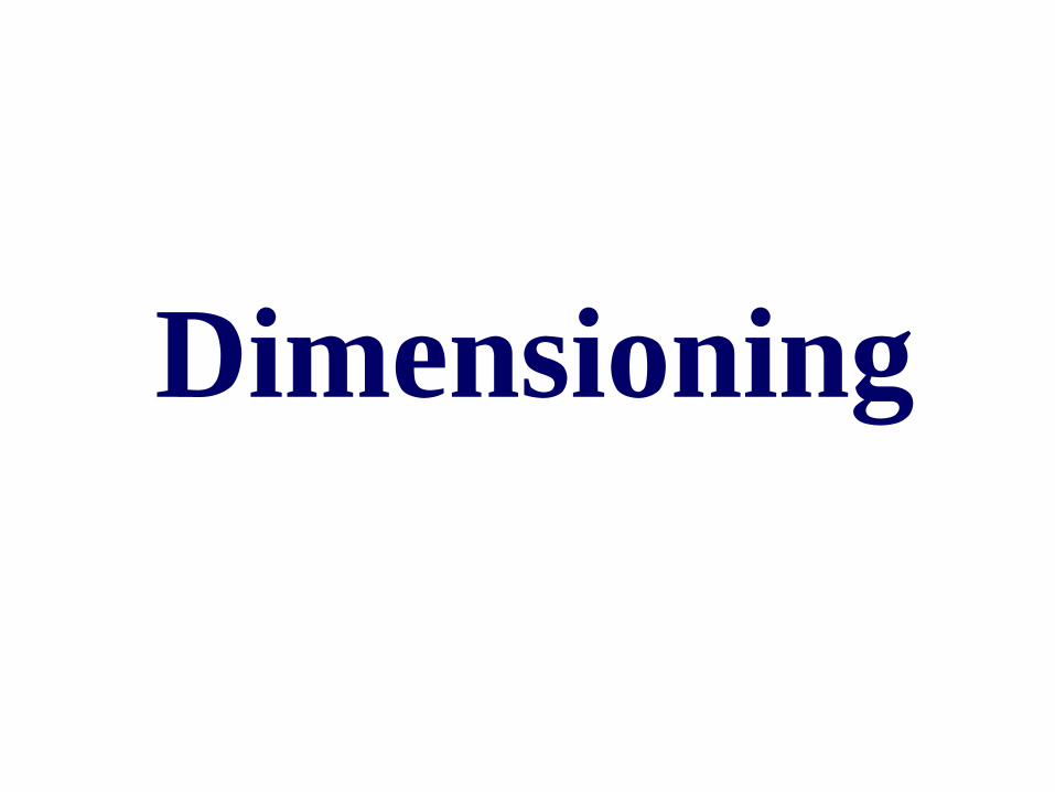
Shape Multiview
Drawing
Dimensioning
Design
a part
1. Size, Location
ENGINEERING DESIGN
2. Non-graphic information
TRANSFERRED
INFORMATION
Create
drawings
Manufacture
RESULT
Sketches
of ideas
PROCESS
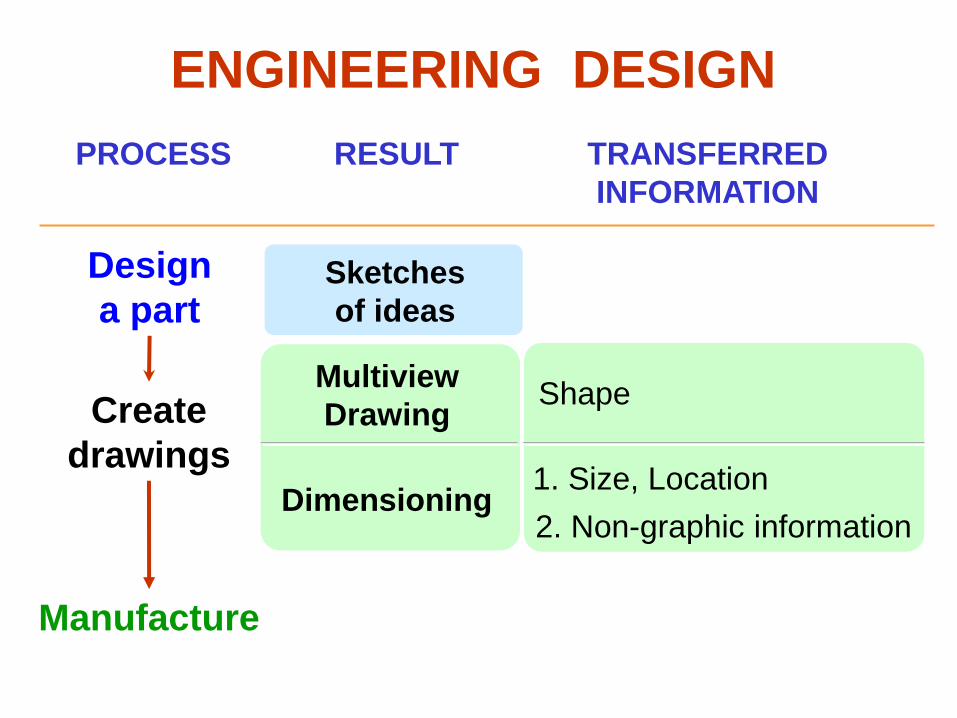
DEFINITION
Dimensioning is the process of specifying part’ s
information by using of figures, symbols and notes.
This information are such as:
1. Sizes and locations of features
2. Material’s type
3. Number required
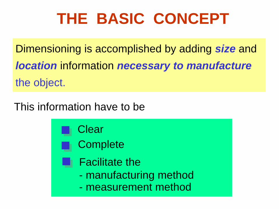
THE BASIC CONCEPT
Dimensioning is accomplished by adding size and
location information necessary to manufacture
the object.
Clear Complete
Facilitate the
- manufacturing method - measurement method
This information have to be
L
L
S
S
S
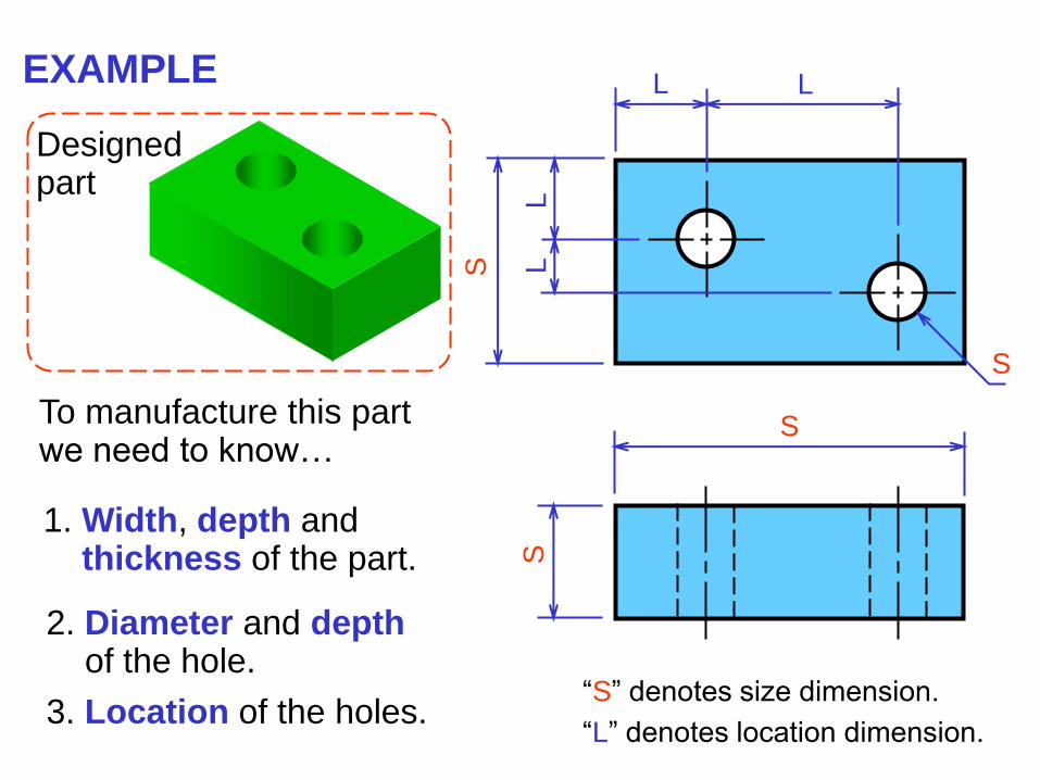
Designed part
EXAMPLE
To manufacture this part we need to know…
1. Width, depth and thickness of the part.
2. Diameter and depth of the hole.
3. Location of the holes. “S” denotes size dimension.
“L” denotes location dimension.
S
L
L
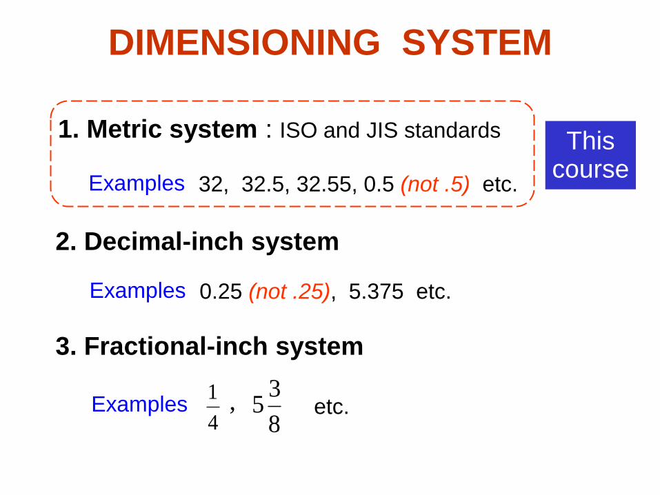
DIMENSIONING SYSTEM
4
1
1. Metric system : ISO and JIS standards
2. Decimal-inch system
3. Fractional-inch system
8
35,
0.25 (not .25), 5.375 etc. Examples
Examples
32, 32.5, 32.55, 0.5 (not .5) etc. Examples
etc.
This course
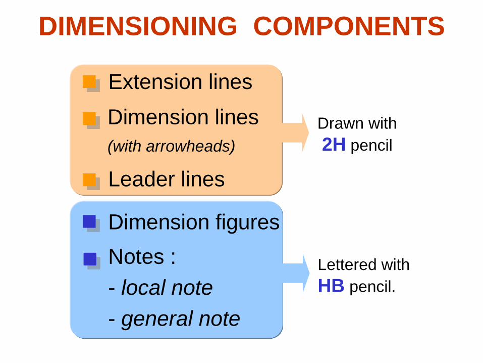
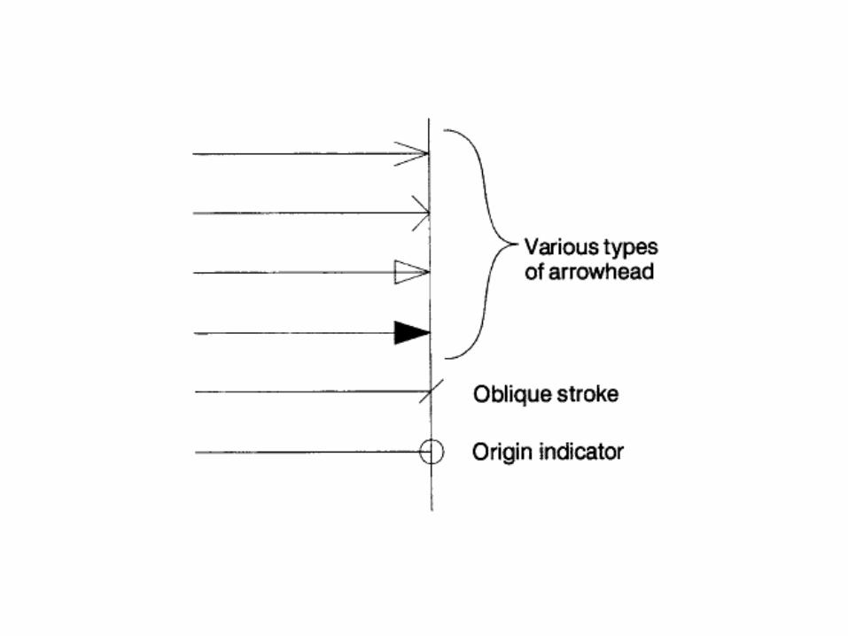
DIMENSIONING COMPONENTS
Extension lines
Dimension lines
(with arrowheads)
Leader lines
Dimension figures
Notes :
- local note
- general note
Drawn with
2H pencil
Lettered with
HB pencil.
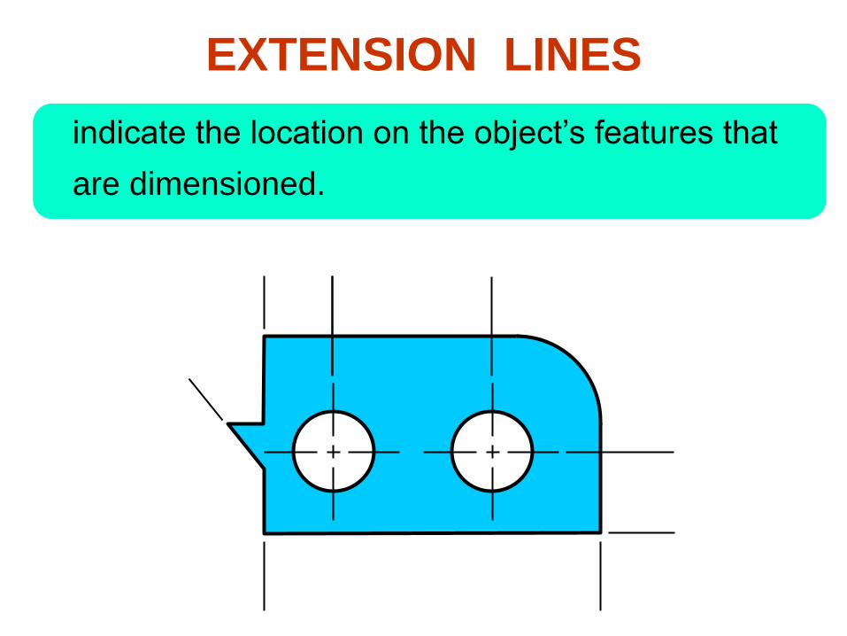
indicate the location on the object’s features that
are dimensioned.
EXTENSION LINES
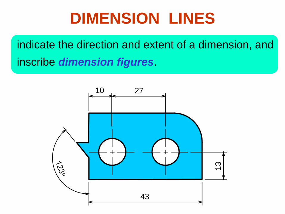
DIMENSION LINES
indicate the direction and extent of a dimension, and
inscribe dimension figures.
10 27
43
13
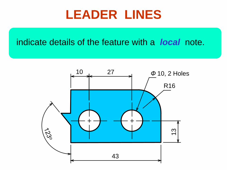
indicate details of the feature with a local note.
LEADER LINES
10 27
43
13
Ф 10, 2 Holes
R16
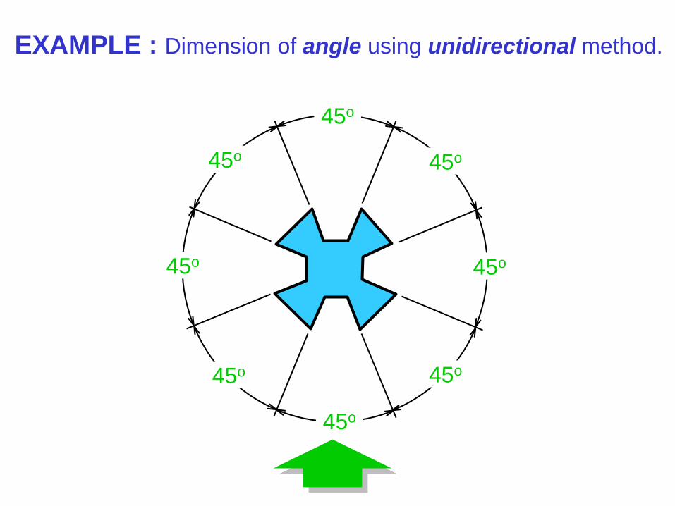
The JIS and ISO standards adopt the unit of
Angular dimension in degree with a symbol “o”
place behind the figures (and if necessary
minutes and seconds may be used together).
DIMENSION FIGURES : UNITS
Length dimension in millimeters without
specifying a unit symbol “mm”.
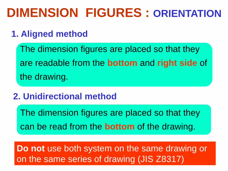
1. Aligned method
2. Unidirectional method
The dimension figures are placed so that they
are readable from the bottom and right side of
the drawing.
The dimension figures are placed so that they
can be read from the bottom of the drawing.
Do not use both system on the same drawing or
on the same series of drawing (JIS Z8317)
DIMENSION FIGURES : ORIENTATION
30
30
30
30
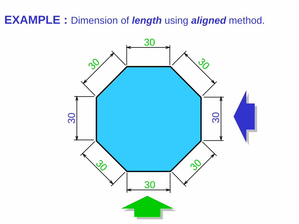
EXAMPLE : Dimension of length using aligned method.
30
30
30
30
30 30
30
30
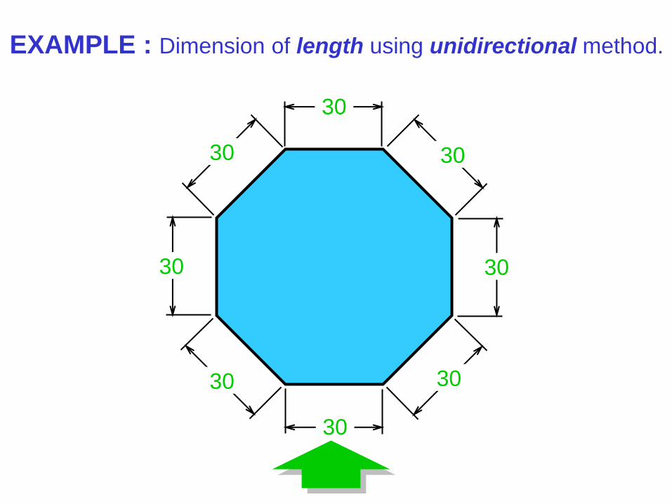
EXAMPLE : Dimension of length using unidirectional method.
45o
45
o
45o
45
o
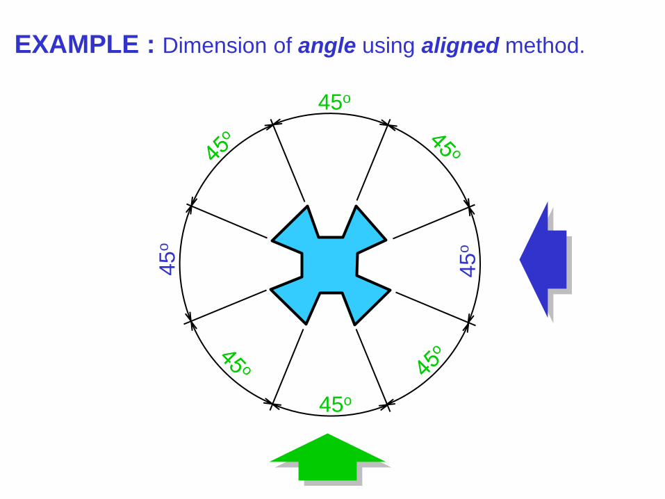
EXAMPLE : Dimension of angle using aligned method.
45o
45o
45o
45o
45o 45o
45o
45o
EXAMPLE : Dimension of angle using unidirectional method.

Recommended
Practices
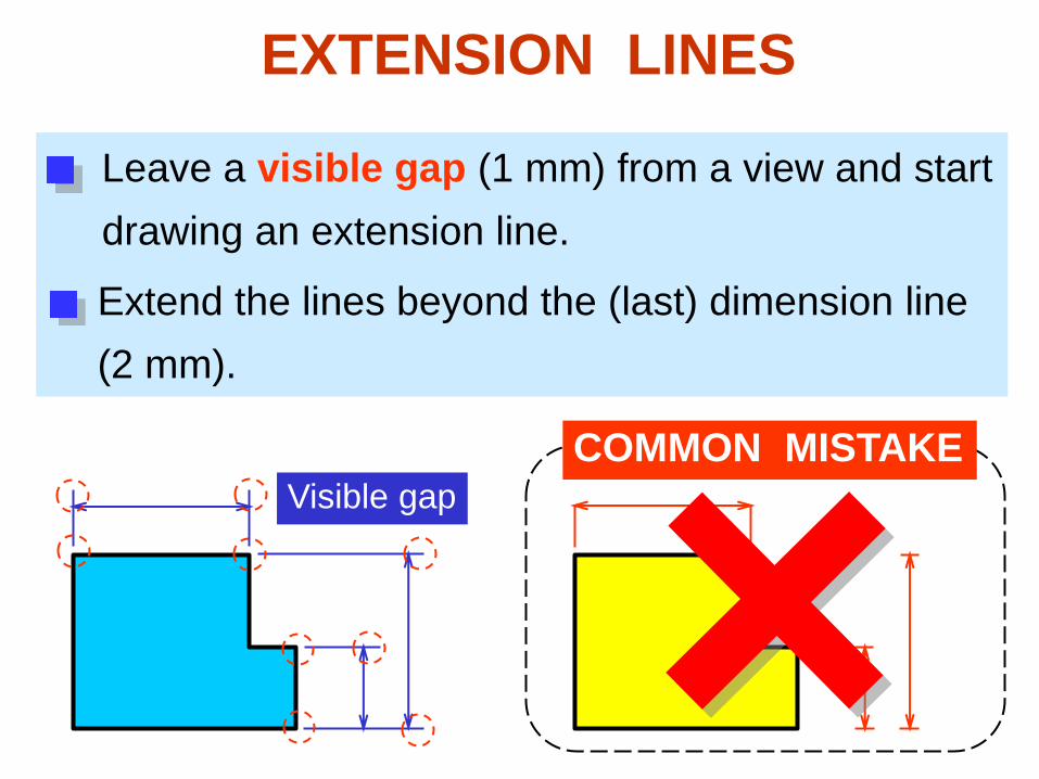
EXTENSION LINES
Leave a visible gap (1 mm) from a view and start
drawing an extension line.
Extend the lines beyond the (last) dimension line
(2 mm).
Visible gap COMMON MISTAKE
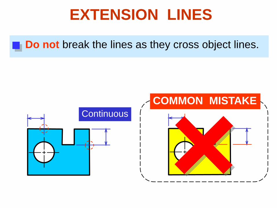
Do not break the lines as they cross object lines.
COMMON MISTAKE Continuous
EXTENSION LINES
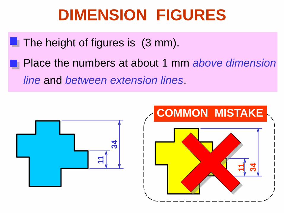
DIMENSION FIGURES
The height of figures is (3 mm).
Place the numbers at about 1 mm above dimension
line and between extension lines.
COMMON MISTAKE
11
11
34
34
16.25 16.25
or
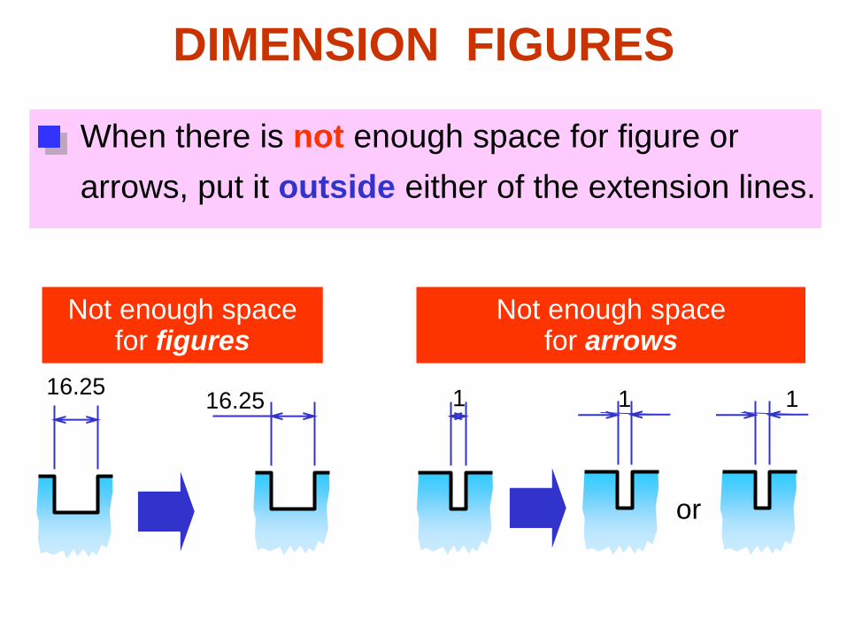
DIMENSION FIGURES
When there is not enough space for figure or
arrows, put it outside either of the extension lines.
1
Not enough space for figures
Not enough space for arrows
1 1
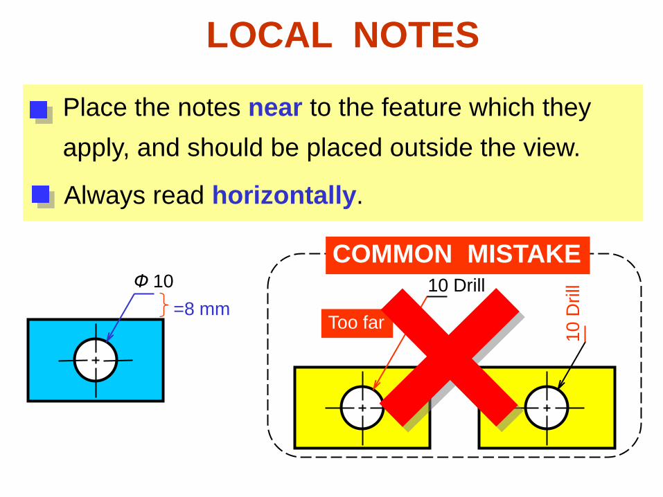
LOCAL NOTES
Place the notes near to the feature which they
apply, and should be placed outside the view.
Always read horizontally.
Ф 10 COMMON MISTAKE
10 Drill =8 mm
10
Dri
ll
Too far

Dimensioning
Practices
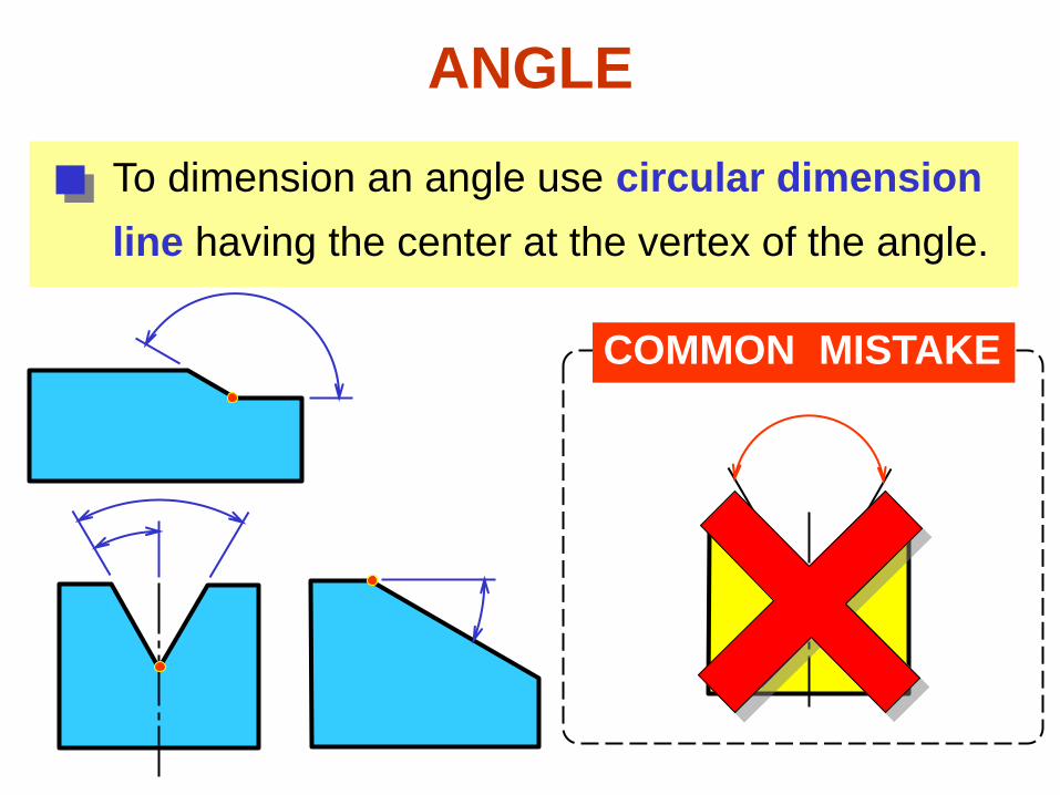
ANGLE
To dimension an angle use circular dimension
line having the center at the vertex of the angle.
COMMON MISTAKE
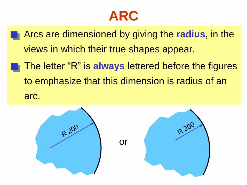
ARC
Arcs are dimensioned by giving the radius, in the
views in which their true shapes appear.
The letter “R” is always lettered before the figures
to emphasize that this dimension is radius of an
arc.
or
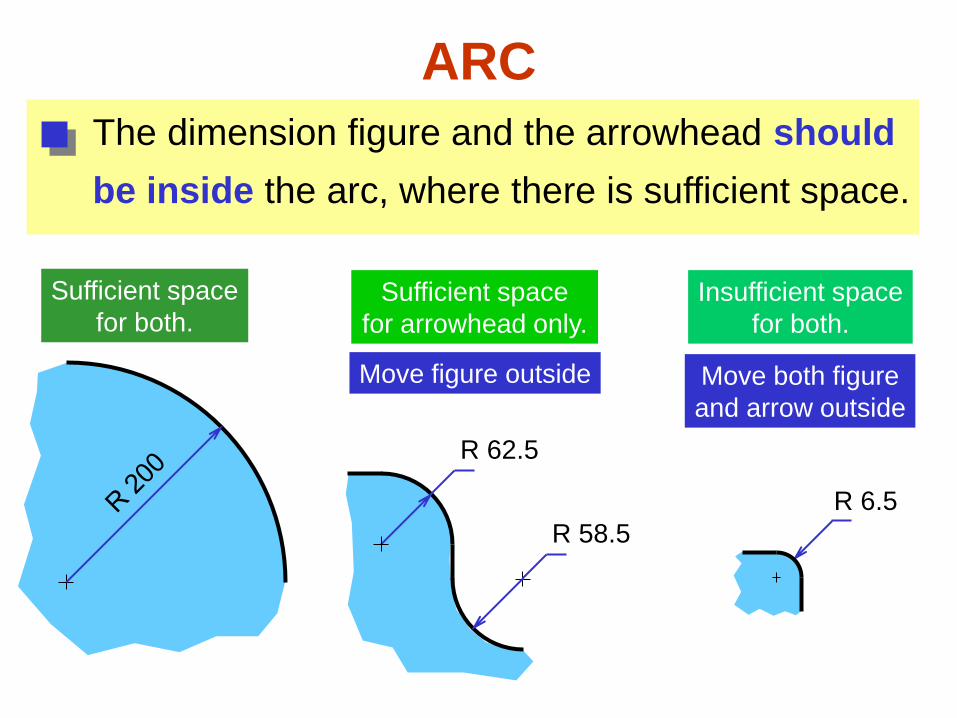
ARC
The dimension figure and the arrowhead should
be inside the arc, where there is sufficient space.
R 62.5
Move figure outside
R 6.5
Move both figure
and arrow outside
Sufficient space
for both. Sufficient space
for arrowhead only.
R 58.5
Insufficient space
for both.
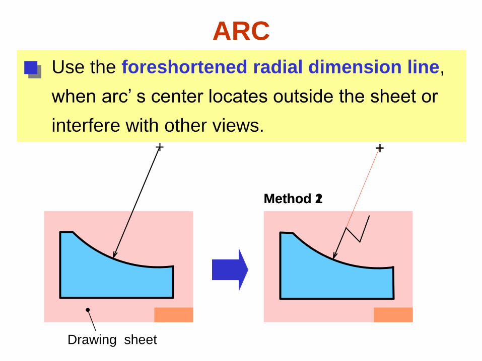
ARC
Use the foreshortened radial dimension line,
when arc’ s center locates outside the sheet or
interfere with other views.
Drawing sheet
Method 1 Method 2
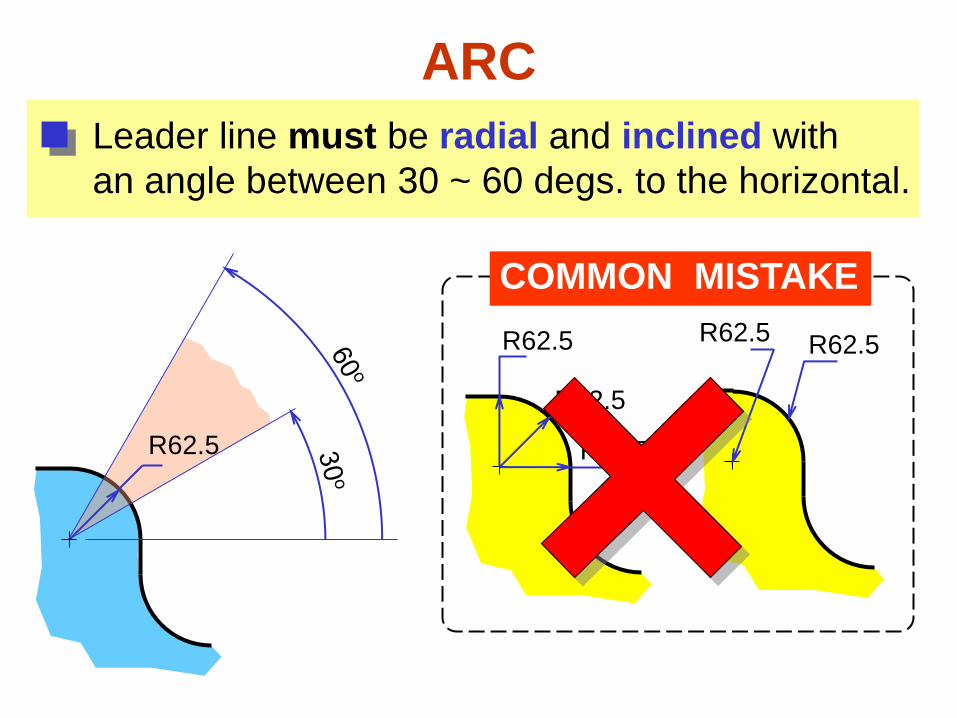
ARC
Leader line must be radial and inclined with
an angle between 30 ~ 60 degs. to the horizontal.
COMMON MISTAKE
R62.5
R62.5
R62.5
R62.5 R62.5
R62.5
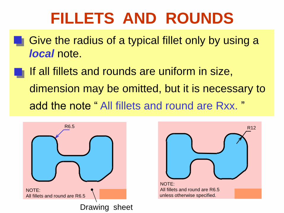
FILLETS AND ROUNDS
Give the radius of a typical fillet only by using a
local note.
R6.5
If all fillets and rounds are uniform in size,
dimension may be omitted, but it is necessary to
add the note “ All fillets and round are Rxx. ”
NOTE:
All fillets and round are R6.5
Drawing sheet
R12
unless otherwise specified. NOTE:
All fillets and round are R6.5
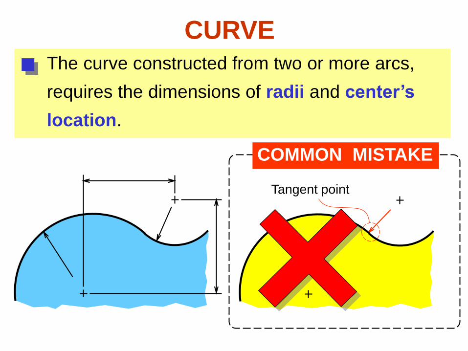
The curve constructed from two or more arcs,
requires the dimensions of radii and center’s
location.
CURVE
COMMON MISTAKE
Tangent point
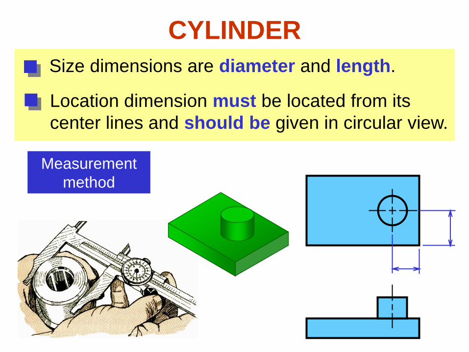
CYLINDER
Size dimensions are diameter and length.
Measurement
method
Location dimension must be located from its
center lines and should be given in circular view.
1
00
7
0
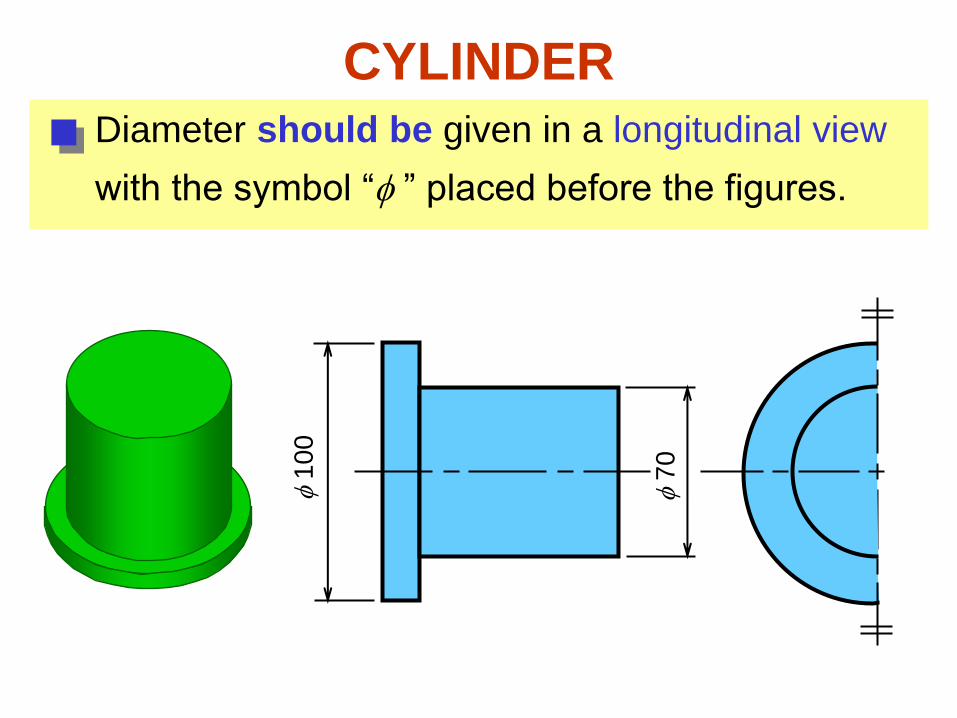
CYLINDER
Diameter should be given in a longitudinal view
with the symbol “ ” placed before the figures.
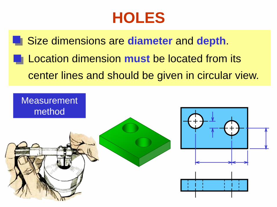
HOLES
Size dimensions are diameter and depth.
Location dimension must be located from its
center lines and should be given in circular view.
Measurement
method
xx
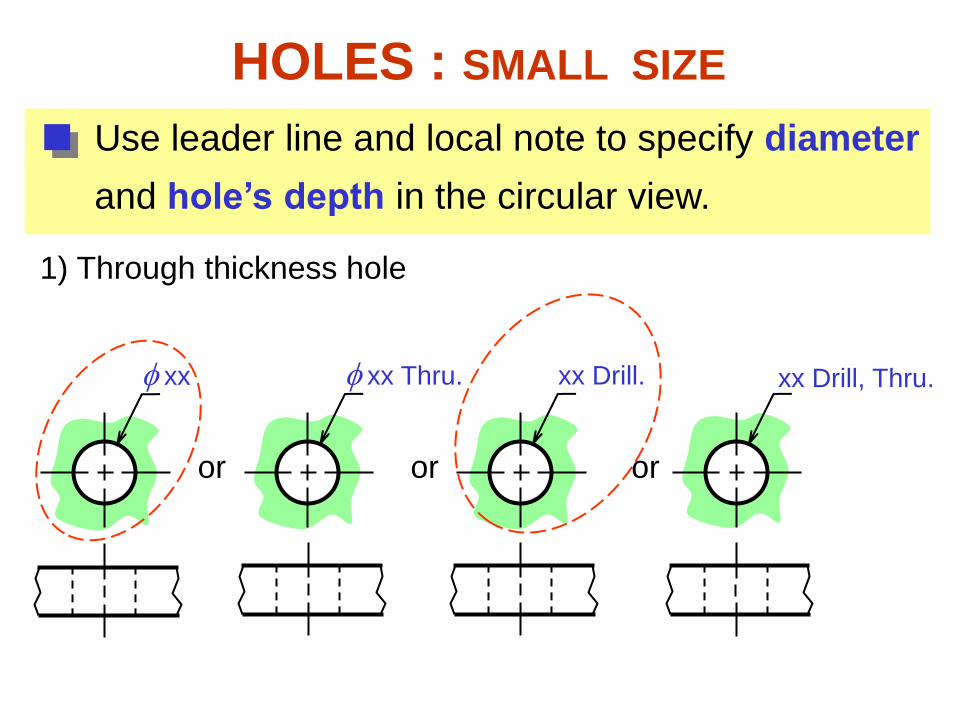
Use leader line and local note to specify diameter
and hole’s depth in the circular view.
HOLES : SMALL SIZE
xx Drill, Thru.
1) Through thickness hole
xx Thru.
or
xx Drill.
or or
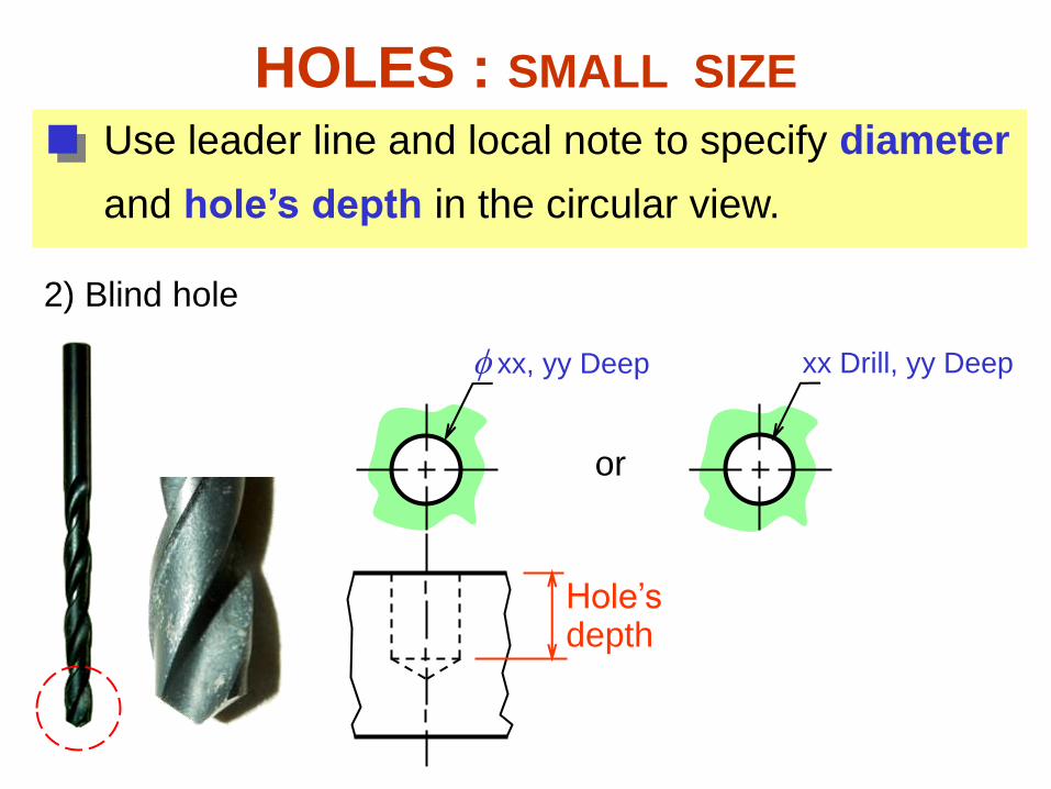
xx, yy Deep
HOLES : SMALL SIZE
or
xx Drill, yy Deep
Hole’s depth
Use leader line and local note to specify diameter
and hole’s depth in the circular view.
2) Blind hole
xx
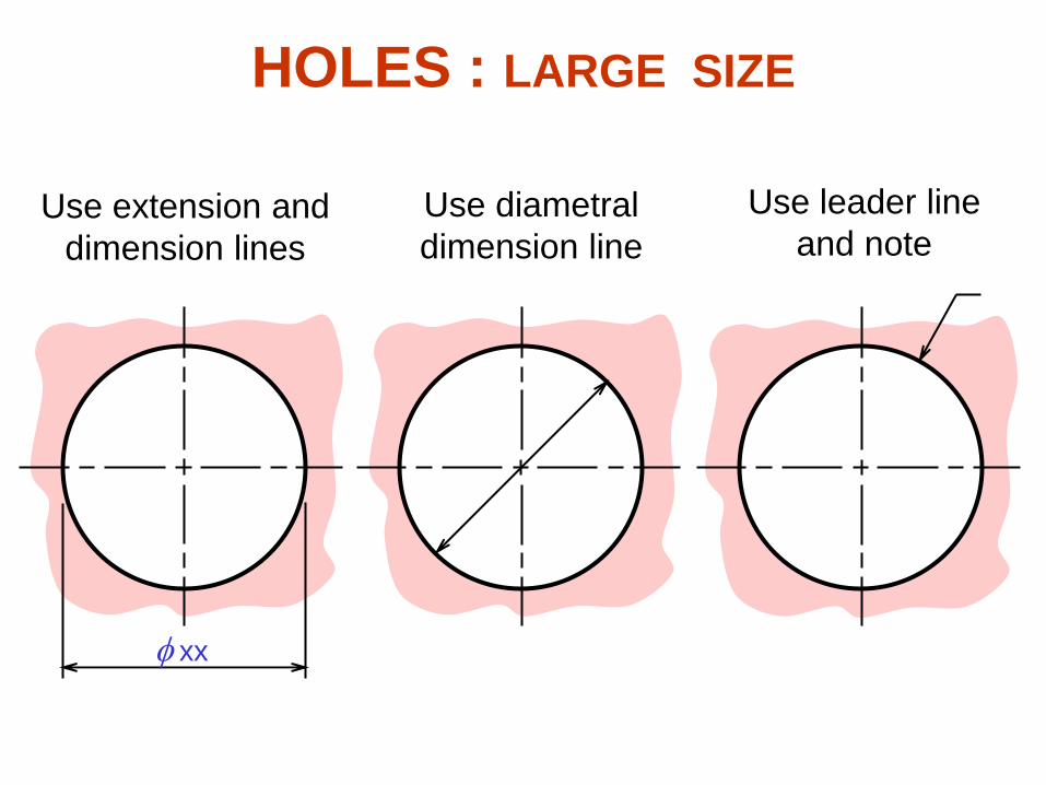
Use extension and
dimension lines
Use diametral
dimension line
Use leader line
and note
HOLES : LARGE SIZE
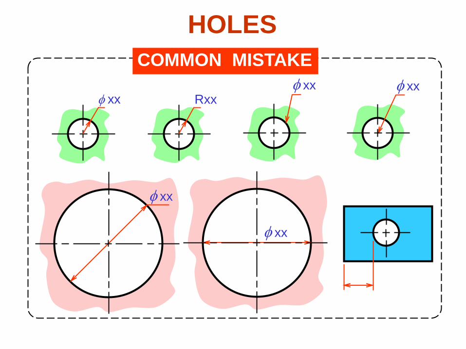
COMMON MISTAKE
xx xx xx
Rxx
xx
HOLES
xx
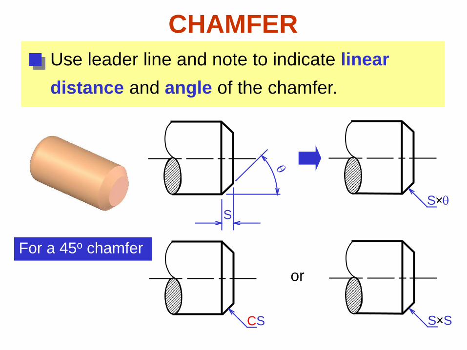
CHAMFER
Use leader line and note to indicate linear
distance and angle of the chamfer.
S S q
For a 45o chamfer
S S CS
or

Placement of
Dimensions
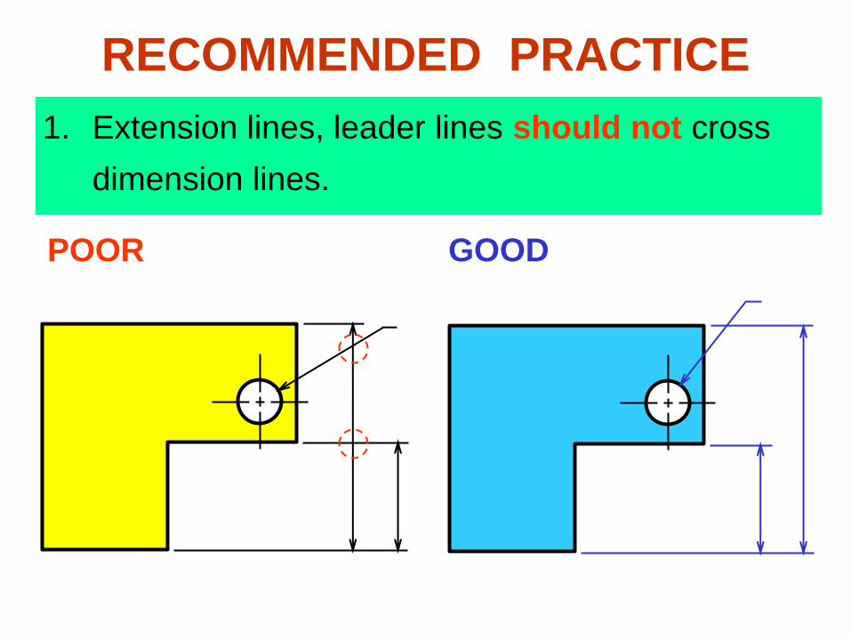
1. Extension lines, leader lines should not cross
dimension lines.
POOR GOOD
RECOMMENDED PRACTICE
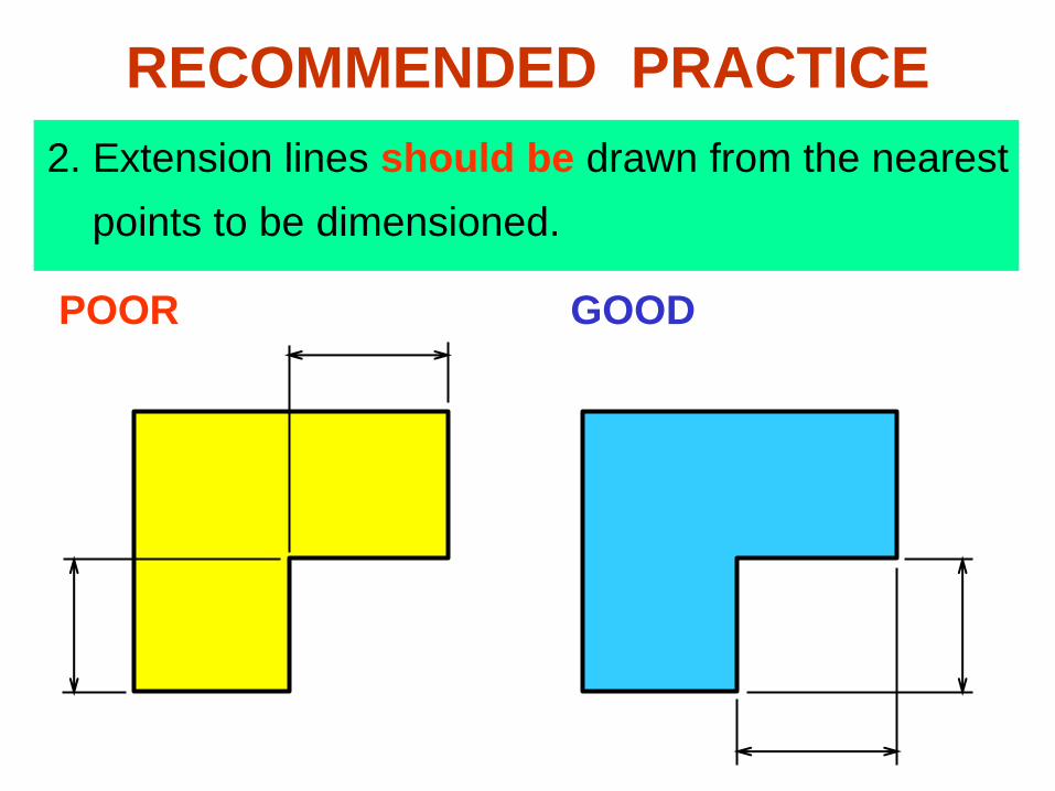
2. Extension lines should be drawn from the nearest
points to be dimensioned.
POOR GOOD
RECOMMENDED PRACTICE
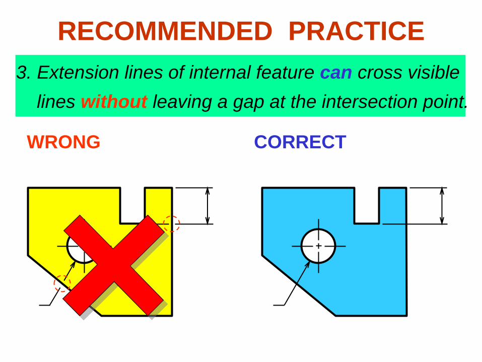
3. Extension lines of internal feature can cross visible
lines without leaving a gap at the intersection point.
WRONG CORRECT
RECOMMENDED PRACTICE
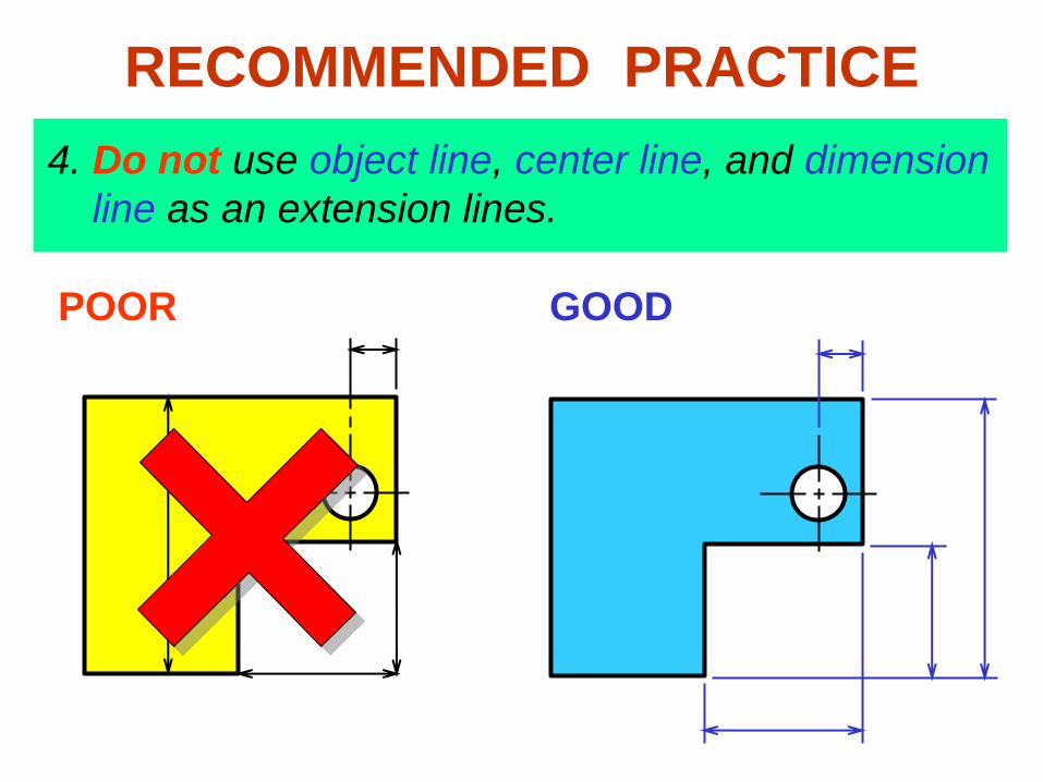
4. Do not use object line, center line, and dimension
line as an extension lines.
POOR GOOD
RECOMMENDED PRACTICE
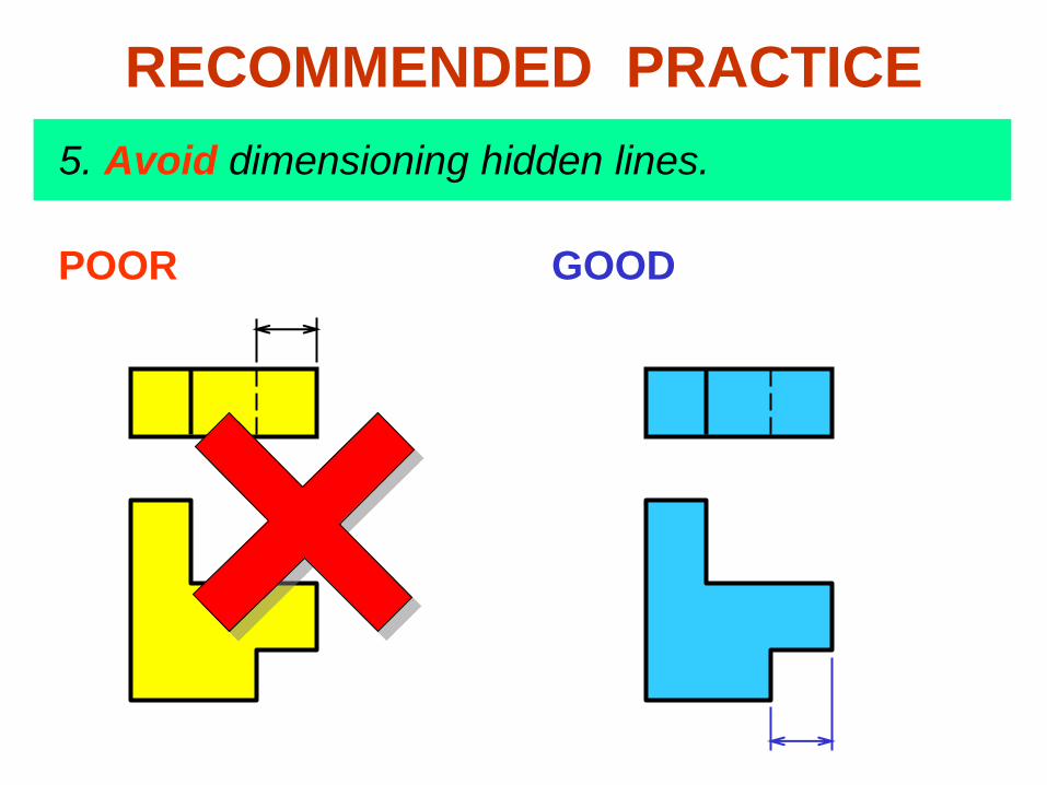
POOR GOOD
5. Avoid dimensioning hidden lines.
RECOMMENDED PRACTICE
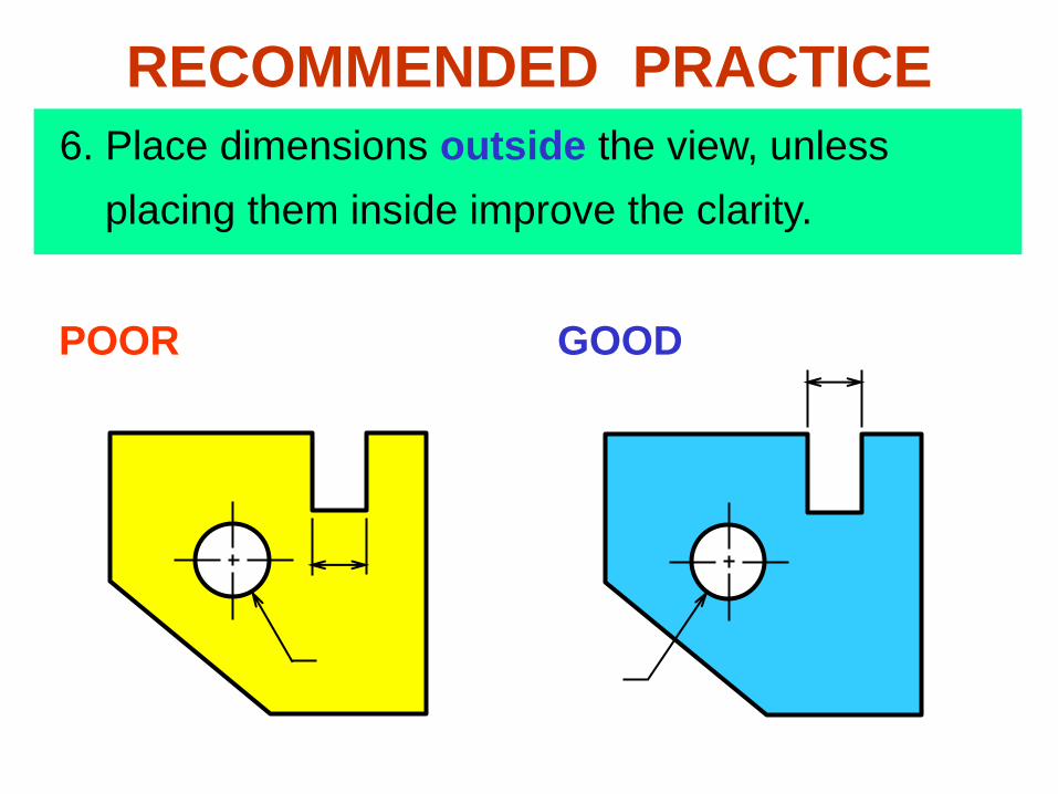
POOR GOOD
6. Place dimensions outside the view, unless
placing them inside improve the clarity.
RECOMMENDED PRACTICE
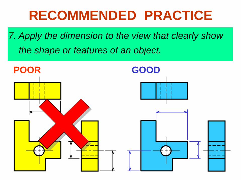
7. Apply the dimension to the view that clearly show
the shape or features of an object.
POOR GOOD
RECOMMENDED PRACTICE
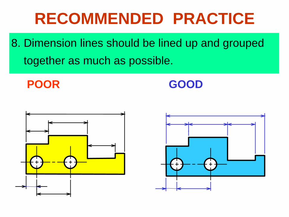
8. Dimension lines should be lined up and grouped
together as much as possible.
POOR GOOD
RECOMMENDED PRACTICE
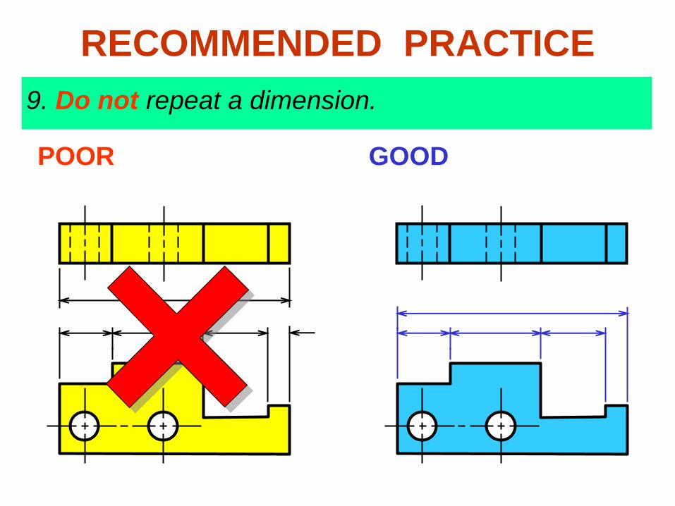
9. Do not repeat a dimension.
POOR GOOD
RECOMMENDED PRACTICE
END

30
30
30
30
EXAMPLE : Dimension of length using aligned method.