Embed Size (px)
Citation preview

SLEVEL __
CONTRACT REPORT ARBRL-CR-00413
00 POST-TEST BLAST RESPONSE ANALYSES
OF DICE THROW VEHICLES
"Prepared by
Kaman AviDyneA Division of Kaman Sciences Corporation
83 Second AvenueBurlington, MA 01803 DTrc
C•ELECTEAPR 231980
January 1980 UB
I•US ARMY ARMAMENT RESE:ARCH AND DEVELOPMENT COMMAND
BALLISTIC RESEARCH LABORATORYABERDEEN PROVING GROUND, MARYLAND
Approved for public release, distribution unlimited.
.. ... 27 02..
"L - .. . . ... .... .. ..... ..__ _ _. . - ... .... ........... ....... . . .. . .. . . . ..... m " m - - =

i -
Destroy this report when it is no longer needed.Do not return it to the originator.
Secondary distribution of this report by originatingor sponsoring activity is prohibited.
Additional copies of this report may be obtainedfrom the National Technical Information Service,U.S. Department of Commerce, Springfield, Virginia22151.
The findings in this report are not to be construed asan official Department of the Army position, unlessso designated by other authorized documents.
Th, WOO of t-.'.e nzam or. namu4nfao•o•u, noma in thia rwportdeoe oonnt".,i"e indoruime"t of mY COMImrcial prodwot.

IiNCLASS I FI iDSECURITY CLASSIFICATION OF THIS PAGE (1When Vote Entered)
S REPORT DOCUMENTATION PAGE READ INSTRUCTIONSREPORTDOCUMENTATIONPAGE BEFORE COMPLETING FORM
I. REPORT NUMBER 2. GOVT ACCESSION NO. 2. RECIPIENT'S CATALOG NUMBER
CONTRACT REPORT ARBRL-CR-0U413 L d)-/k43 __
4 TITLE (and rubtilI.) SI TYPE OF REPORT & PERIOD COVERED
POST-TEST BLAST RESPONSE ANALYSES OF Final ReportDICE "I1IROW VEIIICLIS 26 Jul 77 - I Mar 78
4. PERFORMING ORG. REPORT NUMMERKA TR-150 /
7. AUTHOR(&) 8. CONTRACT OR GRANT NUMNrR(s)
Kenneth R. Wetmore DAAD05-74-C-0744
S. PERFORMING ORGANIZATION N7U 9 AND ADDRESS III PROGRAM ELI.MENtT, PROJECT T'ArKaman AvlI)yne AREA & WO14K UNiT NUMtERI'
A Division of Kaman Sciences Corporation83 Second AvenueBurlington, MA 01803
11. CONTROLLING OFFICE NAME AND ADDRESS 12. REPORT DATEUS Army Armament Research & Development Command JANUARY 1980US Army Ballistic Research Laboratory (DRDAR-BL) IS. NUMBEROrPAGOES
Aberdeen Proving Ground, MD 21005 12314. MONITORING AGENCY NAME A AODREKSSI( dlfferent troam Controlling Office) II. SECURITY"CLAIr? (of tipoti)
UNCLASSIFIED
Ila. tECLASSI ICATION/DOWNGRADEINOISCHEDr ULE.
16. DI•TRINUTION STATEMENT (of this Report)
Approved for public release; distribution unlimited.
17, DISTRIBUTION STATEIMENT (of the abtract entered In Bloak 20, It diffeent from Report
IS. SUPPLEMENTARY NOTES
This research was sponsored by the U.S. Army Project DA No. 1Llh2118A1175,AMCi'S Code 132306.1 1.117200, Nuclear Weapons lffects for Army Applications,Blast and Shock.
IS. KEY WORDSO (Contlinu on favorse side H ncocasa'y and Idantlly by block number)
ID ICF-lTIMROW TestBlast ResponseVehicles
20. ASITRALT (othma - mVem eme t N ,ses'eee md Iderulty by block inmbe.)
This report summarizes the results of a blast response study of selecttruck configurations fielded In the DICE THROW test. Using the TRUCK computercode, the response time-histories of four different Army wheeled vehicle systemsexposed to both blast ovorpressure and dynamic pressure loadings were obtained.Im1Port'int motions of the total systems subsequent to blast wave interception,partlculary vehicle overturning, are plotted.
DO' 1AN73" 147I E oDITlSOf tMOV o.. OSOLETE UNCLASSIIFIEI)SECURITY CLAUIFICATION OF ThIs PAGE (lhm.o Does Entered)

FOREWORD
This work was performed for Ballistic Research Laboratory underContract Number DAAD05-74-C-0744 by Kaman AviDyne, Burlington, Mass., adivision of Kaman Sciences Corporation. The technical monitor for BRLwas Dr. W. Don Allison. Mr. Kenneth R. Wetmore was the project leaderand principal investigator of the study which was performed in theStructural Mechanics Group, headed by Mr. E. S. Criscione, of KamanAviDyne.
The author is indebted to Messrs. R. Raley, G. Teel, N. Ethridgeand Dr. W. Shuman, Jr. of BRL, and to Mr. J. Endicott of MTD, APG forproviding data relevant to the analyses reported herein. The assistanceof Dr. J. Ray Ruetenik and Mr. William N. Lee of Kaman AviDyne in con-figuring the DICE THROW experimental pressure time-history data to theTRUCK computer code aerodynamic loading requirements is also gratefullyacknowledged.
DTIC
ELECTE f1APR 2 3 1980
B
ACCESSION for
NTIS White SectionDDC DllI Sectloo a0NANNOUNKI [3JUSvIlICAION -
YDITRRIOUil0Pq AY , BiUTY W-OS
3 A ,

FOREWORD
This work was performed for Ballistic Research Laboratory underContract Number DAAD05-74-C-0744 by Kaman AviDyne, Burlington, Mass., adivision of Kaman Sciences Corporation. The technical monitor for BRLwas Dr. W. Don Allison. Mr. Kenneth R. Wetmore was the project leaderand principal investigator of the study which was performed in theStructural Mechanics Group, headed by Mr. E. S. Criscione, of KamanAviDyne.
The author is indebted to Messrs. R. Raley, G. Teal, N. Ethridge
and Dr. W. Shuman, Jr. of BRL, and to Mr. J. Endicott of MTD, APG forproviding data relevant to the analyses reported herein. The assistanceof Dr. J. Ray Ruetenik and Mr. William N. Lee of Kaman AviDyne in con-figuring the DICE THROW experimental pressure time-history data to theTRUCK computer code aerodynamic loading requirements is also gratefullyacknowledged.
DTICELECTE ftAPR 2 3 1980
B
ACCESSION or.
NTIS White SectionDDC Bull Section C3UNANNOUNCT D1
SA/Vtl. r) /iN5............ . . . .. . .
3•r

TABLE OF CONTENTS
FOREWORD . . . . . . . . . . . . . . . . . . . . . . . . .. . 3LIST OF ILLUSTRATIONS .. .. .. .. .. .. .. .. .. . .. 7
I. INTRODUCTION ....................... 9
2. VEHICLE SYSTEM CONFIGURATIONS . .. .. .. .. .. . .. 112.1 Introduction .. .. .. .. .. .. .. ..... 112.2 M35A2 Truck Configurations ...... ....... 112.3 M38AI Jeep Configuration .............. 13
3. TRUCK COMPUTER CODE ....................... 153.1 Introduction . . . ................. 153.2 Capabilities of the Code .............. 153.3 Input Data Requirements. .. ........... . 16
4. VEHICLE SYSTEM MECHANICAL MODELS. . . . . . . . . . . . . 194,1 Introduction ........ .. . ..... .. ... 194.2 M35A2 Truck Configurations . . . . . . . . . . . . . 194.3 M38A1 Jeep Configuration . . . . . ...... . 23
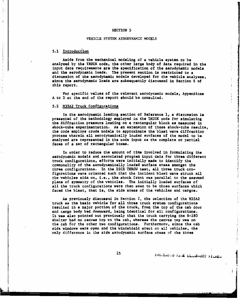
5. VEHICLE SYSTEM AERODYNAMIC MODELS . . . . . . . ... . 255.1 Introduction . . . . . . . . .... .. . 255.2 M35A2 Truck Configurations . . . ........ . 255.3 M38A1 Jeep Configuration .... . . . . . . . .. 26
6. VEHICLE SYSTEM AERODYNAMIC LOADS. . . . . . . . . . . . . 276.1 Introduction ............. ... .. .. .. ... 27
6.2 DICE THROW Experimental Overpressure Data. . . . . . 276.3 Analytical Overpressure and Dynamic Pressure Data.. 27
7. TRUCK RESPONSE ANALYSES RESULTS . . .......... 417.1 Introduction .t.i. ........................ 417.2 TRUCK Response Analysis Parameters . . . . . . . .. 417.3 M38A1 Jeep Response Results .... ............. .... 417.4 M35A2 Truck Response Results . . . . . . ...... 48
5 ~ ~~~~~ 3rL2uAI .'. LAAJJ

TABLE OF CONTENTS (CONT'D)
P age
APPENDIX A INPUT DATA LIST FOR TRUCK CODE - M35A2 TRUCK,EMPTY . ................ ..... 73
APPENDIX B INPUT DATA LIST FOR TRUCK CODE - M35A2 TRUCK,LOADED, WITH CANVAS . .............. 81
APPENDIX C INPUT DATA LIST FOR TRUCK COPL - M35A2 TRUCK,
WITH S280 SHELTER ................. 89
APPENDIX D INPUT DATA LIST FOR TRUCK CODE - M38A1 JEEP . . . . 97
APPENDIX E INPUT DATA LIST FOR TRUCK CODE - M35A2 TRUCK,LOADED, WITHOUT CANVAS. . . . . . . . . . . . . . . 105
DISTRIBUTION LIST. . ............ . . . . . . 113
6

LIST OF ILLUSTRATIONS
Figture Page
1. M35A2 Truck ................................. 12
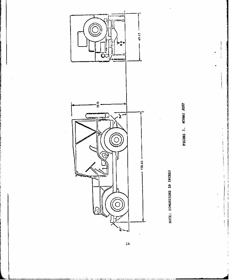
2. M38Ai Jeep ........................ 14
3. Schematic of S280 Shelter in M35A2 Truck .......... 21
4. Schematic of Concrete Blocks in M35A2 Truck ..... 22
5. Experimental Overpressure Time-History at GageStation 324-2 ....... . . . .. . . . . . . . 28
6. Experimental Overpressure Time-History at GageStation 324-3 . . . . ... .......... 29
7. Experimental Overpressure Time-History at GageStation 322-3........... ... . . . . . . . . . 30
8. Experimental Overpressure Time-History at GageStation 322-2 ... . . . . . * , 6 9 0 . 31
9. Experimental Overpressure Time-History at GageStation 223 . . . . . . . . . . . . . . . . . . . . 32
10. C.G. Margin Time-History for M38A1 Jeep Subjectedto 12.9 psi Incident Overpressure (88.9 kPa), . . 42
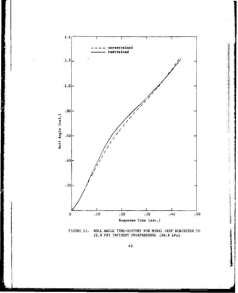
11. Roll Angle Time-History for M38A1 Jeep Subjectedto 12,9 psi Incident Overpressure (88,9 kPa) ... 43
12. Lateral C.G. Displacement Time-History for M38A1 JeepSubjected to 12.9 psi Incident Overpressure (88.9 kPa) 44
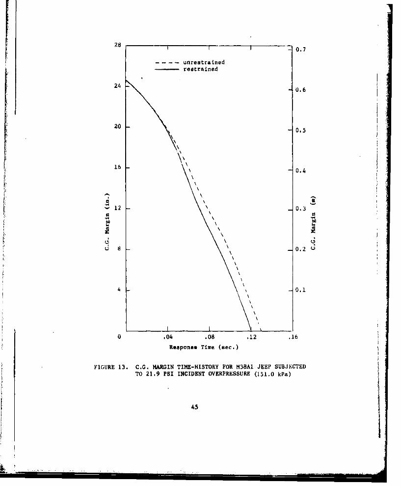
13. C.G. Margin Time-History for M38A1 Jeep Subjectedto 21,9 psi Incident Overpressure (151.0 kPa) .... 45
14. Roll Angle Time-History for M38AI Jeep Subjectedto 21.9 psi Incident Overpressure (151.0 kPa) . .0. . 46
15. Lateral C.G. Displacement Time-History for M38A1 JeepSubjected to 21.9 psi Incident Overpressure (151.0 kPa) 47
16. C.G. Margin Time-History for M35A2 Empty TruckSubjected to 13.9 psi Incident Overpressure (95.8 kPa) 49
17. Roll Angle Time-History for M35A2 Empty Truck Subjectedto 13.9 psi Incident Overpressure (95.8 kPa) . . . . . 50
18. Lateral C.G. Displacement Time-History for M35A2 EmptyTruck Subjected to 13.9 psi Incident Overpressure(95.8 kPa) ..... .............. . . . . . . . . . 51
19. C.G. Margin Time-History for M35A2 Empty TruckSubjected to 21.6 psi Incident Overpressure (148.9 kPa) 52
20. Roll Angle Time-History for M35A2 Empty Truck Subjectedto 21.6 psi Incident Overpressure (148.9 kPa). 53
21. Lateral C.G. Displacement Time-History for M35A2Empty Truck Subjected to 21.6 psi Incident Over-pressure (148.9 kPa) .... ... .......... 54
7

r
LIST OF ILLUSTRATIONS (CONT'D)
Figure Page
22. C.G. Margin Time-History for Restrained M35A2 LoadedTruck Subjected to 12.9 psi Incident Overpressure(88.9 kPa). . . ...... . . . ......... . . . . 56
23. Roll Angle Time-History for Restrained M35A2 LoadedTruck Subjected to 12.9 psi Incident Overpressure(88.9 kPa). . . . .......... . . . . . . . 57
24. Lateral C.G. Displacement Time-History for RestrainedM35A2 Loaded Truck Subjected to 12.9 psi IncidentOverpressure (88.9 kPa)........... . . . . . . 58
25. C.G. Margin Time-History for Unrestrained M35A2Loaded Truck Subjected to 12.9 psi Incident Over-pressure (88.9 kPa) ... .... ............ 59
26. Roll Angle Time-History for Unrestrained M35A2 LoadedTruck Subjected to 12.9 psi Incident Overpressure(88.9 kPa) . . . . . . . . . . ........... 60
27. Lateral C.G. Displacement Time-History for UnrestrainedM35A2 Loaded Truck Subjected to 12.9 psi IncidentOverpressure (88.9 kPa).... . . t.......... . 61
28. C.G. Margin Time-History for Restrained M35A2 LoadedTruck Subjected to 21.9 psi Incident Overpressure(151.0 kPa) . . .. .. .. . ... 63
29. Roll Angle Time-History for Restrained M35A2 LoadedTruck Subjected to 21.9 psi Incident Overprcssure(151.0 kPa) . . .... ... ... . . . ... .. ... 64
30. Lateral C.G. Displacement Time-History for RestrainedM35A2 Loaded Truck Subjected to 21.9 psi IncidentOverpressure (151.0 kPa). .......... . . . 65
31. C.G. Margin Time-History for Unrestrained M35A2Loaded Truck Subjected to 21.9 psi IncidentOverpressure (151.0 kPa)............. . . . . . 66
32. Roll Angle Time-History for Unrestrained M35A2Loaded Truck Subjected to 21.9 psi IncidentOverpressure (151.0 kPa). . . . .. ....... . 67
33. Lateral C.G. Displacement Time-History for UnrestrainedM35A2 Loaded Truck Subjected to 21.9 psi IncidentOverpressure (151.0 kPa) ....... ...... ...... 68
34. C.G. Margin Time-History for M35A2 Truck CarryingS-280 Shelter . . . . . . . . . ................... 69
35. Roll Angle Time-History for M35A2 Truck CarryingS-280 Shelter ...... ................... 70
36. Lateral C.G. Displacement Time-History for M35A2Truck Carrying S-280 Shelter ................ .... 71
8

SECTION 1
INTRODUCTION
The response of tracked and wheeled vehicles to blast waves in atactical nuclear warfare scenario is of considerable interest to militaryplanners. In order to predict such response, Kaman AviDyne previouslydeveloped for the U.S. Army Ballistic Research Laboratory a complexcomputer program called TRUCK.
The TRUCK program, Reference 1, was originally developed to analyzethe blast response of either a soft- or hard-mounted communicationsshelter on a truck, including either soft- or hard-mounted equipmentracks within the shelter. As such, both gross motions of the truck,including vehicle overturning, and motions of the shelter and its internalequipment relative to the vehicle body are considered in the programresponse through inclusion of the necessary multiple degrees of freedom.For less complex dynamic models involving a smaller number of degrees offreedom, the code retains its inherent ability to predict blast-inducedsystem response but with a reduction both in modeling requirements andcomputer running time.
In the study presently being reported, the TRUCK program was appliedto the analysis of four different Army wheeled vehicle systems exposedto blast loading in the DICE THROW field test. During this event, whichtook place on 6 October 1976 at the White Sands Missile Range, New Mexico,the Ballistic Research Laboratory conducted projects concerned withdetermining the response of communication systems and a number of vehiclesto the blast loading. Additionally, the Ballistic Research Laboratoryperformed measurements to document the air blast phenomena, and the measuredpressure time histories were the basis of the aerodynamic loadings employedin the TRUCK analyses. Three of the vehicle systems studied were differentload configurations of a 2 1/2-ton M35A2 cargo truck while the fourthsystem examined was a 1/4-ton M38A1 utility truck, commonly referred toas a jeep.
Three of the four wheeled vehicle systems were analyzed for twodifferent incident pressure levels and two different vehicle restraintconditions in order to simulate the actual conditions experienced by thesystems in DICE THROW. The-fourth vehicle system was analyzed only atone incident pressure level and one restraint condition.
Reference 1. Hobbs, N.P., et at, TRUCK-A Digital Computer Program forCalculating the Response of Army Vehicles to Blast Waves,Kaman AviDyne TR-136, March, 1977.
9

In Section 2, a discussion of the various vehicle and loadingronfiguratione analyzed in this study is presented. A brief overview ofthe TRUCK computer code capabilities and input data requirements isincluded in Section 3. Sections 4 and 5 describe the mechanical andaerodynamic models, respectively, developed for the various vehiclesystem configurAtions analyzed. The aerodynamic loads employed in theTRUCK response runs for the various vehicle systems are included inSection 6, and Section 7 presents the results of the TRUCK analyses.Finally, Appendices A to E contain the TRUCK code input data listingsfor the system configurations analyzed.
10

SECTION 2
VEHICLE SYSTEM CONFIGURATIONS
2.1 Introduction
As stated in Section 1, blast response analyses of four differentArmy wheeled vehicle systems exposed to blast in the DICE THROW fieldtest were conducted in the presently reported ,tudy. Three of thesewheeled vehicle systems were basically M35A2 cargo trucks with differentload configurations, while the fourth vehicle was an M38A1 utility truckoften referred to as an M38A1 jeep.
2.2 M35A2 Truck Configurations
The configurations of the truck systems to be analyzed were specifiedin References 2 and 3 as (1) an M35A2C truck with an S-280 communicationsshelter tied down in the cargo body, (2) an M35 truck with stake sidesbut no load in the cargo body, and (3) an M35 truck with canvas topraised over the cargo body and loaded with concrete blocks to simulatecargo. All three configurations were specified as including no winch onthe vehicle.
Figure 1, which was used as a guide in formulating the computermodels, is an unaltered copy of an original drawing of the 2 1/2-ton,M35A2 cargo truck and shows the basic truck dimensions. Attempts atdifferentiating between the major characteristics and dimensions of theM35, M35A2 and M35A2C truck versions were, as a whole, unsuccessful andthe minor dimensional differences which were determined were consideredto be relatively unimportant. Consequently, the primary configurationof the M35A2 truck without winch, as dimensioned in Figure 1, was employedas a base for configuring the three truck versions to be analyzed.
The major components of the M35A2 truck are the cab, the engine,the cargo body, the frame or chassis which supports those three components,and the running gear. Of these major components, only the cab and thecargo body can be reconfigured.
The top of the cab above the doors is a supported canvas structurewhich is removable, and the cab windshield may be either erect or foldeddown onto the top of the engine hood when the cab top is removed. Thecargo body bed is solid structure at the front and sides and extendsvertically approximately 14 inches (.36m) above the cargo bed floor.The rear of the cargo bed may be either open or closed, depending upon
Reference 2. Contract "Scope of Work" Statement.
Reference 3. Wheeled vehicle and shelter physical data contained inprivate communication from Noel Ethridge of BRL inSpring, 1977.
L 11

VIM
IAO 30SI9
j HL. laggu
- - ~JO
4.-
Iz
12

whether the movable tailgate is down or up. Although not clearly indicatedin Figure 1, the cargo body may be reconfigured with stake sides suchthat both the front and sides of the truck are enclosed by gappedlongitudinal slats attached to vertical stakes which extend to a heightof approximately 36 1/2 inches (.93m) above the cargo bed floor.Additionally, wLth the insertion of bowed support frames above the stakesides, a canvas top may be added which completely encloses the cargobody on the front and sides and leaves only a small opening at the rearof the truck.
As analyzed in this study, then, all three of the previouslymentioned truck configurations from the top of the cab door and the topof the cargo body bed downward, which represents the unchangeableportions of the vehicle, were identical and as shown in Figure 1.Additionally, for all three configurations the cab side windows wereopen, the windshield was erect, and the cargo body tailgate was in an upposition. For configuration (1), the only addition to this base con-figuration was an S-280 shelter tied down in the cargo bed. No canvastop on the cab was included in configuration (1). Configuration (2)included the canvas top on the cab, no load in the cargo body bed, butthe slatted stake sides were erected on the cargo body. Configuration(3) also included the canvas top on the cab, a 5300 pound (2404 kg)load of concrete blocks and supporting timbers rested on the cargo bedfloor, and the canvas top was erected to enclose the cargo body.
2.3 M38AI Jeep Configuration
Unlike the three different M35A2 truck configurations requiringanalysis, only one basic configuration of the M38AI jeep was analyzed.As specified in Reference 2, the basic configuration to be examined wasthe jeep empty, with no canvas.
The specification of jeep empty indicated that no cargo was onboardthe vehicle and the specification of no canvas indicated that neitherthe removable canvas top nor the removable canvas side curtains were onthe vehicle. Figure 2 portrays the 1/4-ton M38A1 jeep with canvas toperected but without the side curtains. The basic configuration of thejeep so analyzed, then, was as shown in Figure 2 but with the canvas topremoved from the vehicle. The possibility that the windshield wasfolded down onto the hood, achievable only in the no canvas condition,in the DICE THROW field test is of negligible importance as will beindicated later in the report.
13
L.
C 00)
I C,
-, Alz
'00
10o
14

SECTION 3
TRUCK COMPUTER CODE
3.1 Introduction
The computer code which was employed to analyze the response of thevehicles discussed in Section 2 to blast exposure in DICE THROW was theTRUCK computer code. Within this section, only an overview of thecapabilities and input requirements of the code will be presented.Reference 1, Kaman AviDyne's report on the development of TRUCK, shouldbe referred to for explicit details of the program.
3.2 Capabilities of the Code
The TRUCK code was formulated basically to have the capability ofanalyzing the response of a truck-mounted communications shelter exposedto a blast wave. In its simplest concept, therefore, consideration hadto be given to items such as the non-linearity of the vehicle suspensionsystem and the complex tire-ground interaction effects. Required con-sideration of the possibility of either or both of the shelter and itsinternal equipment racks being soft-mounted instead of rigidly attachedadded to the program development complexity. Additional consideration ofall or part of the vehicle lifting off the ground or even overturning,as well as consideration of both the diffraction and drag loading phasesof an arbitrarily oriented blast wave, further increased the programscope.
As finally developed, the code has the capability of analyzing theresponse to an arbitrarily oriented blast wave of either a hard- orsoft-mounted shelter, with either hard- or soft-mounted internal racks,on a wheeled or tracked vehicle, with a non-linear suspension system,and parked on a possibly inclined surface. The large number of degreesof freedom included within the program permit examination of largedisplacements and rotations of the vehicle including overturning, aswell as individual motions of the vehicle axles, the shelter, and theinternal shelter racks, relative to the vehicle body. Bottoming andrebounding of the suspension system springs are included in the code,and the tire-ground interaction modeling permits the tire to leave theground, to recontact the ground, to slide along the ground, and to stopsliding.
Options within the code permit repression of various degrees offreedom when analyzing problems of lesser complexity than those indicatedabove. The truck and jeep configurations analyzed in this study, forexample, did not require consideration of all the degrees of freedomavailable within the code. This point may beat be illustrated bydescribing certain of the input data requirements as they applied to thestudy.
15

3.3 Inut Data Requirements
The majority of the input data required by the TRUCK code may becharacterized, in general, as mass data, spring data, tire-ground data,aerodynamic model data, and aerodynamic load data. The present discussionwill be restricted to a general analysis of the TRUCK input data require-ments, since following sections of the report discuss in more detailspecific modeling procedures relevant to the input data requirements ofthis study.
The mass data require specification of the individual values of themass, center of gravity location, and mass moments of Inertia for all ofthe following items which may be individually suspended: the vehiclebody, the vehicle axle assemblies (axle assembly includes axle, wheelsand tires, springs and shock absorbers), the shelter, and the internalshelter equipment racks. For truck configuration (1), the M35A2 truckcarrying the S-280 shelter, the shelter internal racks were rigidlyattached to the shelter and the shelter itself was rigidly attached tothe truck cargo bed floor. Therefore, both the shelter and the internalracks were included as part of the vehicle body mass, leaving only thevehicle body and the axle assemblies as the individually suspendedmasses requiring input data definition. For truck configuration (2),the M35A2 truck with stake sides but with no load, again the vehiclebody and the axle assemblies were the only masses requiring definition.The M35A2 truck with canvas top and loaded with concrete blocks, truckconfiguration (3), also required only vehicle body and axle assembly massdata input since the concrete blocks were not spring mounted and wereincluded as part of the vehicle body mass. Similarly, since the M38AIjeep carried no cargo, only the vehicle body and the axle assembliesrequired individual mass identification.
The spring data portion of the input data defines the character-istics of the spring systems which couple the aforementioned individuallysuspended mass items. As previously indicated, all of the four vehiclesystems analyzed required specification only of the individually sus-pended vehicle body and axle assembly masses, and correspondingly onlythe spring systems linking these masses required definition. It shouldbe noted that the term spring system is used in the general sense andincludes both actual springs as well as shock absorbers. In specifyingthe characteristics of the spring system, the locations of the attach-ment points of each of the springs are required to define the line ofaction of the spring force. Additionally, data defining the non-linearspring force-displacement and damping force-velocity curves for boththe compression and rebound phases of each spring are required.
The tire-ground data required by TRUCK are those data which definethe interaction between the vehicle's tires and the ground. For eachtire on the vehicle, the program requires information on the tire locationon the vehicle, the tire radius, and the coefficient of sliding friction
16

between the tire and surface upon which it rests. Additionally, thenon-linear force-normal displacement and force-tangential displacementdata as well as the radial and tangential tire damping coefficients mustbe provided. Since the three truck systems analyzed involved the sameM35A2 vehicle, all of the tire-ground input data were identical for allthree truck configurations but differed from the M38A1 Jeep data.
The TRUCK input data defining the blast loading on the vehicle area combination of the aerodynamic model data and the aerodynamic loaddata. The aerodynamic model data require that the vehicle system to beanalyzed be broken down into a finite number of rectangular boxes com-prising the total aerodynamic model of the system. Each rectangular boxin turn establishes a specific geometry relevant to both the diffractionloading of the incident blast wave and the drag loading associated withthe material velocity behind the shock front. The aerodynamic load dataare necessary to define the time-history of the blast loading to beapplied to the aerodynamic model and are comprised of the blast over-pressure time-history and the material velocity time-history. Sinceall of the aerodynamic models and some of the aerodynamic load data weredifferent for each of the four vehicle system configurations analyzed inthis study, further discussion of these data will be deferred to latersections of the report.
17

SECTION 4
VEHICLE SYSTEM MECHANICAL MODELS
4.1 Introduction
As indicated in the previous section, the majority of the TRUCKcode input data may be generally grouped into mass data, spring data,tire-ground interaction data, aerodynamic model data, and aerodynamicload data. The first three of these data groups may be more specificallycharacterized as mechanical model data relevant to the physical featuresof a vehicle system. The aerodynamic model and load data developmentwill be subsequently discussed in Sections 5 and 6 respectively, whilethe re.ainder of this section will be exclusively devoted to themechanical model development of the four primary vehicle system con-figurations analyzed in this study.
Appendices A to D should be referred to for specific values ofrelevant mechanical model data.
4.2 M35A2 Truck Configurations
As indicated in Section 3, the only portions of all three trucksystem configurations which normally would have required separate massmodeling to satisfy the input data requirements were the vehicJ.e bodyand the vehicle running gear, since none of the cargos carried wereindependently suspended. However, since the running gear were identicalfor all three truck configurations due to the assumed commonality ofthe primary vehicles, only the vehicle bodies required different modelsin order to account for the differences in the cargo configurations.
It should be noted that the TRUCK code inherently assumes that anysystem to be modeled is laterally symmetrical. Hence, in modeling thevehicle systems for this study, any asymmetries of the vehicle or cargowere ignored, and the lateral c.g. location of each mass was assumed tolie in a vertical plane passing through the mid-points of the vehicleaxles.
References 3 and 4 were used to first establish the mass, c.g.location, and mass moments of inertia about the e.g. of an empty M35A2truck with stal.e sides but without running gear. These values thenwere used as the vehicle body mass data for the no-load truck config-uration. For the truck configuration involving the S-280 shelter
Reference 4. "Preliminary Target Description Data for the Calculationof the Response of a Truck-Shelter-Rack System Exposed toa Blast Wave, and Proposed Test Procedures for ObtainingSuch Data" prepared by R-Associates for BRL underContract No. DAADO5-74-C-0754.
19

rigidly mounted in the vehicle cargo body (Figure 3), the mass, c.g.location, and mass moments of inertia about the shelter e.g. wereestablished from data contained in Reference 3. The shelter mass andc.g. were then combined with the vehicle body mass and c.g. for theno-load truck configuration to obtain a combined truck-shelter massand center of-gravity. Mass moments of inertia about the combinede.g. were then calculated to complete the vehicle body mass data forthe combined truck-shelter system. For the truck configuration involvingthe truck cargo body loaded with concrete blocks and covered with thecanvas top, a procedure similar to the above was employed to obtain aset of combined truck-load mass data.
The configuration of the concrete blocks carried in the truck cargobody was as portrayed in Figure 4. based on information provided byReference 5, and the configuration of the canvas covering the cargobody was estimated from Figure 1. Individual mass data for both theconcrete blocks and the canvas top were then calculated and combined,as previously indicated, with the no-load vehicle body mass data toobtain a complete set of combined truck-load mass data.
The M35A2 vehicle running gear is comprised of a single frontaxle assembly and a dual rear axle assembly. The front axle assemblyconsists of an axle attached to a single wheel on each side of thevehicle, while the dual rear axle assembly, a bogie arrangement,consists of two axles, each attached to dual wheels on either side ofthe vehicle. The front suspension system on each side of the vehicleis comprised of a leaf-type spring and a shock absorber, each itemattached to both the chassis and to the front axle. The rear suspensionsystem on each side of the vehicle contains no shock absorbers per se,but does have one leaf-type spring attached at each end to one of thedual rear axles and at its mid-point to the vehicle chassis.
The separate mass data for each of the three M35A2 wheel-axlecombinations were established from the data contained in References3 and 4. The spring and shock absorber attachment point locations weregiven in Reference 4, and Reference 6 was were used to establish thespring and shock absorber response characteristics. Since the samevehicle running gear were modeled for all three truck configurations,the mass and spring input data remained constant.
Due to the commonality of the running gear on all three configura-tions, the tire-ground interaction modeling was the same for all threeconfigurations except for the coefficient of sliding friction betweenthe vehicle tires and the ground. Although all of the trucks wereassumed to be sitting on level ground in the DICE THROW field test,
Reference 5. Telephone conversation with Mr. R. Raley of BRL on
August 2, 1977.
Reference 6. "Determination of Physical Characteristics of a WheeledVehicle," USATECOM Project No. 9-CO-150-000, Test RecordNo. TU-W-162, Materiel Testing Directorate, U.S. ArmyAberdeen Proving Ground, 16 September 1977.
20

--- II
It
21,_ _ I I.
L---.-
C I
- I
VP N
I-Ii
21

r; i
Ln W,
t IA
F..W-
22i

different restraint conditions were imposed on two of the three truckconfigurations. Since the truck carrying the S-280 shelter was un-restrained from sliding, a coefficient of sliding friction of 0.8,from Reference 4, was used in the TRUCK code input for this vehicle.For each of the remaining two truck configurations, two vehicles ofthe same configuration but with different sliding restraints werefielded in the test event at each pressure level. For each of thesetwo configurations, one vehicle was unrestrained from normal slidingmotion and the second vehicle was restrained from sliding by concretecurbs placed against the tires on the leeward side of the vehicle.Each unrestrained vehicle was modeled with a coefficient of slidingfriction of 0.8, and the restrained vehicles were modeled with acoefficient of 1000, thus effectively restricting the sliding of thetruck. The remainder of the data required by the tire-ground inter-action modeling for all three truck configurations were establishedfrom the data contained in Reference 4.
4.3 M38Al Jeep Configuration
The one M38A1 Jeep configuration modeled was the empty, no canvasconfiguration previously discussed in Section 2. Separate mass modelsfor both the vehicle body and the vehicle running gear were establishedfrom the data presented in References 3, 4 and 7.
The M38AI running gear consists of single front and rear axleassemblies, with each axle attached to a single wheel on each side ofthe vehicle. The front and rear suspension systems of the Jeep aresimilar in that each suspension system on each side of the vehicle iscomprised of both a leaf-type spring and a shock absorber, and theattachment points on the vehicle for these items were obtained fromReference 4. The response characteristics of the Jeep front and rearsprings and shock absorbers required for the TRUCK input were takenfrom Reference 4, since MTD test data on the Jeep springs and shockswere not available as they were for the M35A2 truck.
The tire-ground interaction modeling necessary to satisfy theTRUCK input data requirements for the jeep followed the same generalpattern established for the M35A2 truck configurations, even thoughthe tire size for the two vehicles differed. At each pressure levelanalyzed, two jeeps of the same configuration were fielded in DICETHROW, one restrained and one unrestrained against sliding. Coefficientsof sliding friction of 1000 and 0.8, as used for the M35A2 truckc, werealso used for the Jeep to represent the different restraint conditions,and the vehicles again were assumed to be sitting on level ground inthe field test. The remainder of the tire-ground interaction modeldata were also established from information contained in Reference 4.
Reference 7. "Measurement of Weight, Center-of-Gravity, and Moment-of-Inertia About the Roll Axis of Test Item (Truck, Utility,1/4-Ton, 4X4, M38AI)", USATECOM Project No. 9-CO-150-000-019,Test Record No. TU-W-155, Materiel Testing Directorate,U.S. Army Aberdeen Proving Ground, 10 March 1977.
23 .j
SECTION 5
VEHICLE SYSTEM AERODYNAMIC MODELS
5.1 Introduction
Aside from the mechanical modeling of a vehicle system to beanalyzed by the TRUCK code, the other large body of data required in theinput data requirements are the specification of the aerodynamic modelsand the aerodynamic loads. The present section is restricted to adiscussion of the aerodynamic models developed for the vehicle analyses,since the aerodynamic loads are subsequently discussed in Section 6 ofthis report.
For specific values of the relevant aerodynamic models, AppendicesA to D at the end of the report should be consulted.
5.2 M35A2 Truck Configurations
In the aerodynamic loading section of Reference 1, a discussion ispresented of the methodology employed in the TRUCK code for simulatingthe diffraction pressure loading on a rectangular block as measured inshock-tube experimentation. As an extension of these shock-tube results,the code employs crude models to approximate the blast wave diffractionprocess wherein all aerodynamically lodded surfaces of the model to beanalyzed are represented in the code input as the complete or partialfaces of a set of rectangular boxes.
In order to reduce the amount of time involved in formulating theaerodynamic models and associated program input data for three differenttruck configurations, efforts were initially made to identify thecommonality of the aerodynamically loaded surface areas amongst thethree configurations. In the DICE THROW test, all three truck con-figurations were oriented such that the incident blast wave struck allthe vehicles side on, i.e., the shock front was parallel to the assumedplane of symmetry of the vehicles. The initially loaded surfaces ofall the truck configurations were then seen to be those surfaces whichfaced the blast, that is, the side areas of the vehicles and cargos.
As previously discussaed in Section 2, the selection of the M35A2truck as the basic vehicle for all three truck system configurationsresulted in a major portion of the truck, from the top of the cab doorand cargo body bed downward, being identical for all configurations.It was also pointed out previously that the truck carrying the S-280shelter had no canvas top on the cab, whereas the canvas top was onthe cab for the other two configurations. Furthermore, since the cabside windows were open and the windshield erect on all vehicles, theonly difference in the side aerodynamic surface areas of the three
25 LiL4L U.us.J1

truck cabs was due to the side-on area of the cab canvas top. Sincethe combined side-on areas of the windshield and cab canvas top aresmall in comparison with the side areas of the remainder of the truck,it was decided to simplify the modeling by ignoring the cab top suchthat all three configurations, exclusive of the cargo body, would havethe same aerodynamic surface area.
Each of the three truck system configurations was aerodynamicallymodeled to consist of three rectangular boxes. One rectangular boxrepresented that portion of the truck forward of the cargo body,another rectangular box represented the remainder of the truck belowthe top of the cargo body bed, and both of these boxes were identicalfor all three truck-system configurations. The third rectangular boxwas modeled to represent the aerodynamic surfaces above the top ofthe cargo body bed and, hence, was different for each of the threeconfigurations.
For the empty truck with stake sides, the third rectangular boxwas modeled to represent the aerodynamic surface areas of the slatted,stake sides of the cargo body. The modeling of the truck with canvastop and loaded with concrete blocks required that the third rectangularbox represent only the canvas top over the cargo body since the concreteblocks contributed nothing to the aerodynamic model. The third rectang-ular box for the truck loaded with the S-280 shelter represented onlythat portion of the shelter which protruded above the top of the cargobody bed.
5.3 M38A1 Jeep Confiauration
The aerodynamic model for the one M38A1 Jeep configuration analyzed,empty with no canvas, was based on the configuration of the Jeep inFigure 2 but without the portrayed canvas top. Since the Jeep fieldedin DICE THROW was also oriented side-on to the blast, the initiallyloaded surface areas of the vehicle were those areas shown in theside view of Figure 2. The side-on area of the windshield, as viewedin Figure 2, was considered negligible and, hence, the assumption ofeither an upright or lowered windshield was irrelevant.
The aerodynamic model of the Jeep was constructed as fourrectangular aerodynamic boxes. The first aerodynamic box was modeledto represent the forward portion of the vehicle ahead of the windshield.The second aerodynamic box was modeled to represent the small portionof the body between the windshield and the driver's seat. The aftportion of the body between the driver's seat and the aft end of thevehicle was represented by the third box, and the fourth box approximatedthe spare tire on the rear of the vehicle as a rectangular box.
26

SECTION 6
VEHICLE SYSTEM AERODYNAMIC LOADS
6.1 Introduction
Section 5 of this report discusses the procedures employed inconstructing the aerodynamic models for the primary vehicle-system
configurations analyzed. In the present section, the derivation of theloads which were applied to these aerodynamic models are discussed.Additionally, the actual loads data which were employed in the TRUCKanalyses are presented herein and are excluded from the input datalistings of Appendices A to D.
6.2 DICE THROW Experimental Overpressure Data
As specified in Reference 2, each of the vehicle-system configura-tions with the exception of the truck carrying the S-280 shelter wereto be analyzed at two different pressure levels, with different slidingrestraint conditions imposed at each pressure level as previouslyindicated. Each of the pressure levels selected by BRL correspondedto actual blast data measurements recorded in DICE THROW in the vicinityof the actual test vehicle-system configurations.
Figures 5 through 9 are time-history plots of blast static overpressuremeasured at various pressure gage stations in DICE THROW, as providedby BRL. The values of peak shock static overpressure indicated by BRIJon Figures 5 through 8 were designated as the appropriate pressure levels forthe analyses to be performed. Specific values for the durations of thepositive phase of the blast overpressure portrayed in Figures 5 through 8were also obtained from BRL (Reference 8). The correspondence of thedesignated pressure levels to the appropriate vehicle-system configurationsas specified by BRL are presented in Table 1, together with positivephase durations and gage station numbers, for completeness. It shouldbe noted that no values of either peak overpressure level or positivephase duration are indicated in Table 1 for the truck carrying the S-280shelter for reasons which will be discussed subsequently.
6.3 Analytical Overpressure and Dynamic Pressure Data
The aerodynamic loads normally used in a TRUCK code responseanalysis are blast model data self-contained within the program. Forthe present correlation response study, however, the aerodynamic loadswhich were to be applied to the aerodynamic models discussed in Section5 were the actual loads measured in the DICE THROW test. Since theTRUCK code employs both blast overpressure and dynamic pressure time-
histories in its simulation of the diffraction and drag loading regimesof blast waves, additional efforts were required to formulate dynamicpressure time-histories compatible with the experimentally-measuredoverpressure time-histories provided.
Reference 8. Telephone conversation with Mr. G. Teal of BRL onSeptember 1, 1977.
27

clN
C)N
N
Lr)0 1 (
en I
VL
4 000 1
T OT X VdX-ZflSSTflda
4' N 0) 00 '4
*oT x isd-amnfssau1
28

0
o -d
Ltn
C14U) -P4w M-
ý4 r-4
LnH
OD 0 N 4
c,4I 0 - N
OOT X lgcT-MTfSSMth
29

.00It.~
0 L0
"41.
N P-4
t N30

0
I I I
en C4
Ln
04 Ih .7
oG
Ln 0 Lfu 1C%4 14
No trx isa-nnss~a -
31

C4
en~
LMt
r4 P4
TOT~M X 14WSM
Ooi~~U~ x I-ms
32i

H~4 ( 4 4 4 N
4-.
4).
8o
cn
1.4 14 94 1
0% 4 P4 04 % 0
4.
33

The general procedure used in formulating the required dynamicpressure time-history data was based on a slight modification of themethodology contained in Reference 9. Reference 9 presents ananalytical method which was formulated for computing the pressure,density, and material velocity behind a spherical blast wave, producedby TNT or Pentolite, based on experimental measurements of overpressurerecorded at a number of gage locations. Part of the methodology inReference 9 involves the use of a constructed cross plot of pressure,density, and material velocity behind the shock front, and two keyparameters established from the peak overpressure at the shock front,the ambient pressure ahead of the shock front, and the specific valueof interest of the overpressure behind the shock.
For each of the overpressure traces of Figures 5 through 8, anarbitrary number of overpressure values were first read from a smoothcurve drawn through the data as recorded. Since the ambient pressurewas readily established and the peak overpressure was already specified,it was then possible to calculate the two key parameters, correspondingto each selected overpressure value, which were required to enter thecross plot of Reference 9. Interpolation of the plotted values ofdensity and material velocity behind the shock provided the appropriatedata necessary to formulate values of dynamic pressure correspondingto the selected values of overpressure. At the shock front, a moreaccurate value of dynamic pressure than that obtained from the plot ofReference 9 was independently calculated from normal shock equations.The dynamic pressure data were then plotted against the times aftershock arrival obtained from the original overpressure traces correspondingto the initially chosen values of overpressure, and smooth curves weredrawn through the data to eliminate any minor computational errors. Thefinal list of discrete values of overpressure and dynamic pressure whichwere used in the TRUCK code response analyses to represent the blastwave positive phase duration for each of the specified pressure levelsin Figures 5 through 8 are presented in Tables 2 through 5.
Table 6 presents the discrete values of overpressure and dynamicpressure which were used in the TRUCK code to represent the assumedoverpressure and dynamic pressure time-histories corresponding to GageStation No. 223.
As can be seen from Figure 9, the recorded static overpressuretime-history trace for Station No. 223 was extremely erratic and ill-defined. Since neither the maximum overpressure value at the shock frontnor the positive phase duration could be ascertained from Figure 9 withany degree of confidence, it was impossible to fair a smooth curve throughthe experimental overpressure trace. After reviewing all the availableoverpressure, both static and total, time-histories recorded along theDICE THROW blast line 2, it was decided that the only feasible way toobtain a realistic static overpressure time-history curve for Station No.223 would be through interpolation of the static overpressure datameasured at other blast line 2 pressure gage stations, based on groundrange location of the gages. Consequently, after considerable cross-plotting
Reference 9. Ruetenik, J.R., and Lewis, S.D., Computation of BlastProperties for Spherical TNT or Pentolite From MeasuredPressure Histories, AFFDL-TR-66-47, October 1966.
34

0-0 0 n%0- o. . - o@-%A' o 0 o-%o-. o-
C.. 04 fn M M LM otv c.d .S 01 a:~'~ ~~-%
P4n
%V Nr crt V'-4'
0: . 19 1 . 00 "1N Cý ~0 N - M00.0P4 19
oGo%D -C mn N N 1- P-4M 0
' .00 % . ' . % . % .o % L .
tq Pi9 .., .
90 ,0 r 4 M 04N -
cI
35

N P% .-% 4 D M$%P1 -
%-# %.0 0 -- 0 w . -0 . -
P4 0 wN (CP 7
4H ~ ~ ~ .r% oo N r. w % -Lne -
I 0 00 D w4
04 -VM fn N P l
0ý
36

a .n %t N N 4r4r I i cc co
U h N%0 1^ t-4 m 4£0 Nr.4
- . .. Ch C4 C n %o C
-t 9. 'D4 LA m_ C4 4 C
1-4
37

r% I n eIn s~~%'-b* e ~ . r 0
,, M
I LnN~ fot fo . ...
44WI
38
. .... . ...... ......

rWe 4 40HIC COSO
C Ui - I' - % -
1'.M~O N r- 0~ a0 Ui C
0i~ MM '04 % s 00 00 0 9 ST
P- '041'9N ,-rOO 04
J41
39

of the data pertinent to the various pressure gage stations of blastline 2, a static overpressure time-history curve for Station No. 223was formulated.
Once theformulation of an acceptable curve of static overpressuretime-history for Station No. 223 was accomplished, it was a simple taskto formulate the required compatible dynamic pressure time-history data.The procedure followed was identical to that previously described forFigures 5 through 8 and, as indicated previously, the resultant discretevalues of both overpressure and dynamic pressure used in the TRUCKanalysis of the truck-shelter system are tabulated in Table 6.
40
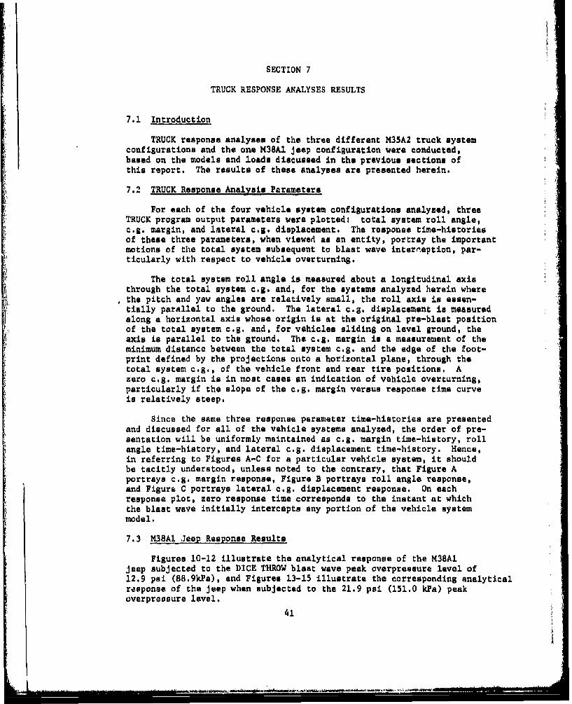
SECTION 7
TRUCK RESPONSE ANALYSES RESULTS
7.1 Introduction
TRUCK response analyses of the three different M35A2 truck systemconfigurations and the one M38A1 jeep configuration were conducted,based on the models and loads discussed in the previous sections ofthis report. The results of these analyses are presented herein.
7.2 TRUCK Response Analysis Parameters
For each of the four vehicle system configurations analyzed, threeTRUCK program output parameters were plotted: total system roll angle,c.g. margin, and lateral c.g. displacement. The response time-historiesof these three parameters, when viewed as an entity, portray the importantmotions of the total system subsequent to blast wave interneption, par-ticularly with respect to vehicle overturning.
The total system roll angle is measured about a longitudinal axisthrough the total system c,g. and, for the systems analyzed herein wherethe pitch and yaw angles are relatively small, the roll axis is essen-tially parallel to the ground. The lateral e.g. displacement is measuredalong a horizontal axis whose origin is at the original pre-blast positionof the total system c.g. and, for vehicles sliding on level ground, theaxis is parallel to the ground. The e.g. margin is a measurement of theminimum distance between the total system e.g. and the edge of the foot-print defined by the projections onto a horizontal plane, through thetotal system e.g., of the vehicle front and rear tire positions. Azero c.g. margin is in most cases an indication of vehicle overturning,particularly if the slope of the c.g. margin versus response time curveis relatively steep.
Since the same three response parameter time-histories are presentedand discussed for all of the vehicle systems analyzed, the order of pre-sentation will be uniformly maintained as c.g. margin time-history, rollangle time-history, and lateral e.g. displacement time-history. Hence,in referring to Figures A-C for a particular vehicle system, it shouldbe tacitly understood, unless noted to the contrary, that Figure Aportrays c.g. margin response, Figure B portrays roll angle response,and Figure C portrays lateral e.g. displacement response. On eachresponse plot, zero response time corresponds to the instant at whichthe blast wave initially intercepts any portion of the vehicle systemmodel.
7.3 M38A1 Jeep Response Results
Figures 10-12 illustrate the analytical response of the M38Aljeep subjected to the DICE THROW blast wave peak overpressure level of12.9 psi (88.9kPa), and Figures 13-15 illustrate the corresponding analyticalresponse of the jeep when subjected to the 21.9 psi (151.0 kPa) peakoverpreosure level.
41

30
unrestrained 0.7
restrained
25-'•, ~0.6 .
20-
• N• N,• x 0.4
Slo •
N\
Sx I~0.2 ,'
15-
-010
0 .05 .10 .15 .20 .25 .30
Response Time (sec.)
FIGURE 10. C.G. MARGIN TIME-HISTORY FOR M38A1 JEEP SUBJECTED TO 12.9PSI INCIDENT OVERPRESSURE (88.9 kPa)
42
.1 .4 . . .
unrestrainedrestrained
1.2
/9
1.0 /:
.80 -
.40
I .20 -
0 .10 .20 .30 .4U .5o0i
Response Time (sec.) :
FIGUJRE 11. ROLL ANGLE TIME-111STORY FOR M38AI ,IEI-'P SUBJECTED) TO12.9 PSI INCIDENT OVERPRESSURE (88.9 kPa)
43
1/
: . . .. .. . . , ... m . ..

35I I I -I/
unrestrained /
restrained /0.8
30 /'
/ - 0.7//
25 /
0/ / -0.6
S ¢~/S20 0.5
0.4
15 /
- 0.3
10/
0.2
5-
0.1
S]I I i
0 .10 .20 .30 .40 .50
Response Time (sec.)
FIGURE 12. LATERAL C.G. DISPLACEMENT TIME-HISTORY FOR M38AIJEEP SUBJECTED TO 12.9 PSI INCIDENT OVERPRESSURE (88.9 kP~a)
44
28 I 0.7
unrestratnedrestrained
24 0.6
20 0.5
16
0.4
12 _0,3
L; 80.2
4 0.1
0 .04 .08 .12 .16
Response Time (sec.)
FIGURE 13. C.G. MARGIN TIME-HISTORY FOR M38A1 JEEP SUBJECTEDTO 21.9 PSI INCIDENT OVERPRESSURE (151.0 kPa)
45

1.4- i I
-unrestrained
restrained
1.2 -•S //,/
//
//
1.0 //
.80/
V
'4 . 60-
.40 -
.20-
0 .04 .08 .12 .1.6
Response Time (sec.) '
FIGURE 14. ROLL ANGLE TIME-HISTORY FOR M38AI JEEP SUBJECTED TOi
21.9 PSI INCIDENT OVERPRESSURE (151.0 kPa)
46
N //I
hi .60,-- • -• . . , .. .. . . .. . .... • . . ;; ,.,..., ., ,.; ., . , . ........ .... . .. .. ... ...... .. .
S. . .i I I I II I i i i--/

F "1.0
unrestrainedrestrained
/ 0.9(.35 / i
//
/ ;4/ •
30- 0.8
30//
/ 0.7// - ,
25 /"t. /
I / 0.6
/Q
U20O / 0.5
U.
' 1 5 / 0.4 d
0_ .3
10
0.2
5-0.1
f . . . J .... .. .. ..... J.. .. ....... .. L..1
U .04 .08 .12 .16
Response Time (sec.)
FIGURE 15. LATERAL C.G. DISPLACLMENT TIME-HISTORY FOR M38A1 JEEPSUBJECTED TO 21.9 PSI INCIDENT OVERPRESSURE (151.0 kPa)
47
- ~ ~ ~ ~ ~ ~ ~ ~ ~ ~ ~ .d I ... W WatoS.f. S' WW.Ct..M,.d

*1
For both overpressure levels analyzed, the comparative resultsshown for the two assumed sliding restraint conditions indicate thatvery little sliding motion of the total system takes place, as evidencedby the closeness of the restrained and unrestrained curves. The slopesof the c.g. m~rgin time-history curves at zero c.g. margin indicatethat overturning of the vehicle occurs at both levels of overpressure,with the system subjected to the higher overpressure overturning muchearlier as would normally be expected due to the higher level of loading.For the higher overpressure level, the values of both roll angle andlateral c.g. displacement at the response time corresponding to zeroc.g. margin are slightly higher than the corresponding values for thelower overpressure level.
7.4 M35A2 Truck Response Results
Figures 16-18 portray the analytical response of the M35A2 emptytruck subjected to the 13.9 psi (95.8 kPa) peak overpressure level, andthe analytical response of the same system subjected to a peak overpressurelevel of 21.6 psi (148.9 kPa) is presented in Figures 19-21.
The. c.g. margin time-history curves indicate that overturning ofthe empty truck also occurs at both overpressure levels analyzed and,again, at a much earlier response time for the higher overpressurelevel. Although the results presented indicate that the restrainedvehicle overturns slightly faster than the unrestrained vehicle and thatrelatively little sliding motion takes place at either overpressure level,it is interesting to note that at the lower overpressure level the vehicleshows a slight hesitancy to overturn as evidenced by the marked changein vehicle roll rate prior to the attainment of a zero value for thec.g, margin. Again, at the higher overpressure level the values of bothroll angle and'lateral c.g. displacement at the response time correspondingto overturning are higher than the corresponding values for the loweroverpressure level, and more so for the roll angle due to the roll ratechange experienced at the lower. overpressure level.
Before discussing the analysis results presented for the responseof the M35A2 loaded trucks containing concrete blocks and subjected tothe two DICE THROW overpressure test levels of 12.9 psi (88.9 kPa) and21.9 psi (151.0 kPa), some background discussion is necessary since theanalyses required procedures different than originally planned. Aspreviously indicated in Sections 4 and 5, a separate mechanical modelwas originally formulated to represent the M35A2 loaded truck withcanvas and a separate aerodynamic box was modeled to represent thecovered cargo body for aerodynamic loading. The combination of thesemodels, together with the two assumed restrained conditions, were to beused to investigate the system response at the two indicated pressurelevels. It was subsequently learned, however, that during the actualDICE THROW experiment the canvas enclosures on the M35A2 loaded truckswere blown off the trucks shortly after blast wave interception and atboth levels of overpressure to be analyzed. Consequently, the actualM35A2 loaded truck configurations which required analysis were systems
48
i[ i i....~lns~V~bt.' , i i.i

40 T!]TTT1.0
unrestrained
restrained35 "0.9
30 •••, .
0.7
20 , 0.7
S0.4 .
U.
10-
0.2
0.1
\'4
0 .05 .10 .15 .20 .25 .30 ,s
Response Time (sec.)
FIGURE 16. C.6. MARGIN TIME-HISTORY FOR H135A2 EMPTY TRUCK SUB.IECTEI) TO13.9 PSI INCIDENT OVERPRESSURE (95.8 kPii)
49

1.4 I i
unrestrained--- restrained
1.0
/
80
.60
.40
.20
I I I I A
0 .10 .20 .30 .40 .50 .60
Response Time (see.,)
FIGURE 17. ROLL ANGLE TIME-4HISTORY FOR M35A2 EMPTY TRUCK SUBJECTED TO13.9 PSI INCIDENT OVERPRESSURE (95.8 kPa)
50

60
unrestrained -1.4restrained
50-/
/VS40- /
/30
0.6 8
0. / 0.4
to-'
I- O //./
S0.2
0.10 .20 .30 .40 .50 .60
Response Time (sec.)
FtGURE. 18. LATERAL, C.(;. DISPLACEMENT TIME-H4ISTORY FOR M35A2 EMPT'YTRUCK SUBJECTED TO 13.9 PSI INCIDENT OVERPRESSURE (95.8 kla)
5 .
/ , , , I I II

40 _______r__ .
Sunreatra1ned
restrained
0.935
0.8
30
25 0.7
~25
\\ - 0.6
,• 20 _o.5
0.4S,.; 15
0.3
10
0.2
0.1\
\
0 .04 .08 .12 .16 .20Response Time (sec.)
FIGURE 19. C.G. MARGIN TIME-HISTORY FOR M35A2 EMPTY TRUCKSUBJECTED TO 21.6 PSI INCIDENT OVERPRESSURE (148.9 kPa)
52

1.4 I i
unrestrained
restrained
1.0/
/
.. .80
.60 /- /0
/! ..40 /
./
.20
i I I
0 .04 .08 .12 .16 .20 .24
Response Time (sec.)
FIGURE 20. ROLL ANGLE TIMF-HISTORY FOR M35A2 EMPTY TRUCK SUBJECTEDTO 21.6 PSI INCIDENT OVERPRESSURE (148.9 kPa)
53

50
unrestrained2restrained
40-,I
08
30 - 0.6/ ,
20-
0.4 -
. ,* /
-0.24 -) - 0)I I'
004 .08 .12 .16 .20 .24
Response Time (sec.)
FIGURE 21. LATERAL C.G. DISPLACEMENT TIME-HISTORY FOR M35A2 EMPTYTRUCK SUBJECTED TO 21.6 PSI INCIDENT OVERPRESSURE (148.9 kPa)
54
ha.S L l i.LL

wbich realistically underwent both mechanical and aerodynamic configurationchanges during the period of system response.
Since the TRUCK code has no provision for configuration changesduring response evaluation, it was apparent that the actual M35A2 loadedtruck responseasimulation could not be properly handled by TRUCK. How-ever, it did appear logical to expect that the actual response of thesystem would be between two extremes - the analytical response of aloaded truck with canvas erected during the entire response time andthe response of a loaded truck without canvas during the entire responsetime. Acceptin6 this premise as valid and having the canvas erect modelsalready at hand, it was only necessary to model the loaded truck withoutcanvas in order to proceed with the intended comparative analyses.
The formulation of the required mechanical model of an M35A2 truckloaded with concrete blocks bit without canvas was relatively simple.The only effort involved was to remove the mass and inertia contribu-tions of the cargo body canvac top from the previously constructed modelwith canvas top, resulting in a new total system model with modifiedmass, inertia, and e.g. characteristics. No additional effort wasinvolved in aerodynamically modeling the loaded truck without canvassince, aerodynamically, that configuration was identical to the aerodynamicconfiguration of the M35A2 empty truck. Specific values of the relevantmechanical and aerodynamic model data for the M35A2 loaded truck withoutcanvas are presented in Appendix E at the end of the report. Once thisnew model was completed, TRUCK response analyses for the loaded truckwith and without canvas were conducted for both require.1 overpressurelevels and both assumed restraint conditions.
The analytical response results for the restrained M35A2 loadedtruck subjected to the 12.9 psi (68.9 kPa) peak overpressure level arepresented in Figures 22-24. Similarly, the results for the unrestrainedvehicle subjected to the same overpressure level are shown in Figures25-27.
For either assumed restraint condition, the plotted re3ults showa most obvious difference in the overall system response of the twovehicles - namely, the vehicle with canvas overturns, as evidenced bythe c.g. margin time-history curve going to zero, but the vehicle withoutcanvas does not, as evidenced by the c.g. margin time-hibtory curvereturning to its original time zero value. Both the restrained andunrestrained vehicles with canvas do show a slight hesitancy to overturn,as indicated by the change in roll rate, but this heasitancy is overcomaand overturning takes place. Again, as was noted in discussing boththe M38A1 jeep and the M35A2 empty truck results, the overall totalmotions of the restrained and unrestrained loaded trucks are quitesimilar, indicating that very little sliding motion of the vehicles hastaken place.
55
[40 IL
with canvaswithout canvas/
0.935-0
O,B
30--
0.7
25 \
0.6
• 20-0.5
I) 0.4 .;
S15- .
0.3
10-
5-
0.1
20 .40 .60 .80 1.0 1.2
Response Time (sec.)
FI(;URE 22. C.G. MARGIN TIME-HISTORY FOR RESTkAINED M35A2 LOADED TRUCKSUBJECTED TO 12.9 PSI INCIDENT OVERPRESSURE (88.9 kPa)
56
V,..............

1.4 r -
-- - with canvas
without canvas
1.02.
/ 1W//
//
.80- /
SI
0-4
.40ý
.20- -
•, • /
0 .20 .40 .60 .80 1.0 1.2
Response Time (sec.)
FIGURE 23. ROLL ANGLE TIME-HISTORY FOR RESTRAINED M35A2 LOADED TRUCKSUBJECTED TO 12.9 PSI INCIDENT OVERPRESSURE (88.9 kPa)
57
/Now

80 .... ... 0I--. I 1 2.0
with canvaswithout canvas
/
70[- /1.8
Il /i /
' I - 1.6/ -
601- i
I
I I
" I I
" /1.
UU
" * Ii
IiU I/ d..I .,i 0 .83 / :3I_
! 0.6
20--
/0.4
I~ // ... •.
/ • -0.2
I /
.20' .40 .60 .80 1.0 1.2
Response Time (see.)
FIGURE 24. LATERAL, C.G. DISPLACEMENT TIME-HISTORY FORRESTRAINWE M35A2LOADED TRUCK SUBJECTED TO 12.9 PSI INCIDENT OVERPRESSURE (88.9 kPa)
58
.......................... .. . . .. . .

40 -,-r- -**--- ,-1 .- . -1- - 1.0
-with canvaswithout canvas
35 - 0 .9
0.8
30
"0.7
25.4 0.6
1510.4i 0.I• \
10 0.5
0.1
I t
0 .20 .40 .60 .80 1.0 1.2
Response Titme (sec.)
FIGURE 25. C.G. MARGIN TINE-HISTORY FOR UNRESTRAINED M35A2 LOADED TRUCKSUBJECTED TO 12.9 PSI INCIDENT OVERPRESSURE (88.9 kPa)
59
Aii -o.,..•

1 . 4 r -... . .. . . . . .. I. . . .. . . . .
-with canvaswithout canvas
1. 21.2-. /
I //
/
/
1.0.- / .
TRUK S
-- "680--
- . /
.6 .- /
-/
/.401--
/ 1 / ----,-* I/
0.0.0.60 .80 1.0 1.2
Response Tite(se.
FI(;URE 26. ROtL ANGLE TIME-HISTORY FOR UNRESTRAINED M35A2 LOADED)TRUCK SUBJECTED TO 12.9 PSI INCIDENT OVERPRESSURE (88.9 kPu)
60
70 1 1 1 I
with canvaswithout canvas /
/ 1.6/
00- //
/, 1.4
/
50-/
/ 1.2/
40- /1.S~/
S/ 0.8 Z4•30 /30
S/ 0.6
20-
20 ,/ 0.4
13 - / - 0.2/ •
/
0 .20 .40 .60 .80 1.0 1.2
Response Time (sec.)
FIGURE 27. LATERAL C.G. DISPLACEMENT TIME-HISTORY FOR UNRESTRAINEDM35A2 LOADED TRUCK SUBJECTED TO 12.9 PSI INCIDENTOVERPRESSURE (88.9 kPa)
61

For the M35A2 loaded truck subjected to the 21.9 psi (151.0 kPa)peak overpressure level, the analytical results are presented in Figures28-30 for the restrained vehicle and in Figures 31-33 for the unrestrainedvehicle. For either restraint condition, the results indicate that boththe vehicle with canvas and the vehicle without canvas overturn, with aslight overturning hesitancy showing up in the roll angle time-historiesof both vehicles. The same previously noted similarity in total vehicleresponse between the restrained and unrestrained vehicles is evident.
Based on the premise that the simulated response of the actualM35A2 loaded trucks in the DICE THROW experiment would fall somewherebetween the analytical responses of a truck with canvas and a truckwithout canvas, the analyses conducted indicate overturning of thetrucks does occur at the 21.9 psi (151.0 kPa) overpressure level but atthe 12.9 psi (88.9 kPa) level a definite conclusion regarding overturningcannot be made. The assumed conditions of restraint for the vehicleshave little or no bearing on these conclusions.
Figures 34-36 indicate the analytical response results for theM35A2 truck carrying the modified S-280 communications shelter. Aspreviously mentioned in Section 4, this configuration as fielded inthe DICE THROW test was unrestrained from sliding and, hence, only acoefficient of sliding friction of 0.8 was used in the TRUCK analysis.Furthermore, this particular vehicle system was subjected to only oneincident overpressure level and, as indicated in Section 6, this levelwas estimated as 12.064 psi (83.18 kPa).
As indicated in Figure 34, the c.g. margin curve rapidly decreasesto a value of zero indicating an overturning vehicle, and both Figure 35and Figure 36 further confirm this overturning occurrence. It shouldbe noted, however, that although Figures 34-36 indicate entirelyreasonable results consistent with the assumed overpressure loading,the validity of accepting these results as indicative of the actualvehicle response is questionable due to the uncertainty of the actualoverpressure time-history at Station 223 in the DICE THROW test.
A summary of the vehicle overturning predictions resulting fromthe TRUCK code analyses of all system cc..figurations reported hereinare presented in Table 7.
62
.... .. .. ... .. .. ... .. n.n..
40
- - with canvaswithout canvas
35-\ 0.9
30-
- 0.7
25
0.6
S20-0.5
10 0.1• \ -0,4
0.2
5-
0.1
0 -. 0 .10 .15 .20 .25 .30
Response Time (sec.)
FIGURE 28. CG. MARGIN TIME-HISTORY FOR RESTRAINED M35A2 LOADED TRUCKSUBJECTED TO 21.9 PSI INCIDENT OVER~PRESSUJRE (151.0 kPa)
63I I • ,.....

1 .4 -. . . . . .
with canvas
without canvas
1.2- 1/
/
I
1.0 I// -
*80 /
.60-
.40 - /
.20 -
0 .10 .20 .30 .40 .50
Response Time (sec.)
FIGURE 29. ROLL ANGLE TIME-HISTORY FOR RESTRAINED M35A2 LOADEDTRUCK SUBJECTED TO 21.9 PSI INCIDENT OVERPRESSURE (151.0 kPa)
64

60 1 1
with canvas 1.4without canvas
50 /1.2
'2, /
-40 - 1.0
300.20/
Qj
;:=• 3 oL / •
060.2
20 .1 .2 3 4 5
I T (e
FIUR 0.4AEA .. DSPAEETTM-ITOYFRRSRIE
/
SI10- /I/ -0.2/
0.10 .20 .30 .40 .50
Response Time (see.)
FIGURE 30. LATERAL e.G. DISPLACEMENT TIME-HISTORY FOR RESTRAINED
M35A2 LOADED TRUCK SUBJECTED TO 21.9 PSI INCIDENTOVERPRESSURE (151.0 kPa)
65
[,L ., • ,• . .

40F i 1.0
---- with canvaswithout canvas
35ý, 0.9
0.8
S30 - \
0.7
25 \
20 - 0.5
W •0.4
~15
U 0.3
10 \
-0.2
5\
\ 0.1\
0 .05 .10 .15 .20 .25 .30
Response Time (sec.)
FIGURE 31. C.G. MARGIN TIME-HISTORY FOR UNRESTRAINED M35A2 LOADEDTRUCK SUBJECTED TO 21.9 PSI INCIDENT OVERPRESSURE (151.0 kPa)
66

with canvaswithout canvas
1.2
.80i
S//SI,
.40 //
/!
.20 i lt
i /
0 .10 .20 .30 .40 .50
Response Time (sec.)
FIGURE 32. ROLY AXGLZ TIME-HISTORY FOR UNRESTRAINED M35A2 LOADEDTRUCK SUBJECTED TO 21.9 PSI INCIDENT OVERPRESSURE (151.0 kPa)
67

60
with canvas 1.4without canvas
5 1.2
•40 /1.0
Sj _ 0.8S30/
d / 0.6
S20
//
S/ 0,///
//
10 i
/
0 .10 .20 .30 .40 .50
Response Time (sec.)
FIGURE 33. LATERAL C.G. DISPLACEMENT TIME•-HISTORY FOR UNRESTRAIt'EDM35A2 LOADED TRUCK SUBJECTED TO 21.9 PSI 1NCIDE1NTOVERPRESSURE (151.0 kPa)
68

40 .
35 -0.9
-0.8
30
0.7
-0.6
"20 _0.5
-0.415
-0.3
10
-0.2
-0.1
0,.10 .20 .30 .40 .50
Response Time (see.)
FIGURE 34. C.G. MARGIN TIME-HISTORY FOR M35A2 TRUCK CARRYING S-280 SHELTER
69
=ME

1.2
.30
-. 60
20
0
.10 .20 .30 .40 .50 .60
Response Time (see.)
FEIGURE 35. ROLL ANGLE TIME-HISTORY FOR M35A2 TRUCK CARRYING S-280 SHELTER
70

60 1 1 .---
1.4
50
H1. 2-. I
~40- 1.0--/ i
lo-
20.
'4 '0.4
I0
/ ,II...1.2L.10 .20 .30 .40 .50 .60
Response Time (sec.)
FIGURE 36. LATERAL C.G. DISPLACEMENT TIME-HISTORY FOR M35A2 TRUCKCARRYING S-280 SHELTER
71

TABLE 7
SYSTEM CONFIGURATION OVERTURNING PREDICTIONS
System Configuration Peak Overpressure Overturning Predictedpsi (kP&a) _
M35A2 truck, with 12.064 (83.18) YesS-280 shelter (assumed)(unrestrained)
M35A2 truck, empty, 13.9 (95.8) Yeswith stake sides 21.6 (148.9) Yes
(unrestrained)
M35A2 truck, empty, 13.9 (95.8) Yeswith stake sides 21.6 (148.9) Yes
(restrained)
M35A2 truck, loaded 12.9 (88.9) Yeswith concrete blocks, 21.9 (151.0) Yeswith canvas top
(unrestrained)
M35A2 truck, loaded 12.9 (88.9) Yeswith concrete blocks, 21.9 (151.0) Yeswith canvas top
(restrained)
M35A2 truck, loaded 12.9 (88.9) Nowith concrete blocks, 21.9 (151.0) Yeswithout canvas top
(unrestrained)
M35A2 truck, loaded 12.9 (88.9) Nowith concrete blocks, 21.9 (151.0) Yeswithout canvas top
(restrained)
M38A1 jeep, empty, 12.9 (88.9) Yeswith no canvas 21.9 (151.0) Yes
(unrestrained)
M38A1 jeep, empty, 12.9 (88.9) Yeswith no canvas 21.9 (151.0) Yes
(restrained)
72

APPENDIX A
INPUT DATA LIST FOR TRUCK CODEM35A2 TRUCK, EMPTY
73
L.. _...... ..

CLC
er 00
a~ fi
U 'i - III
.4 p 0 P
-- % 0.0
1 .4 OM .r LI
0O * 4-4 ~ iI LtI~
P.74
LL

0 0
*0 a a I
* 0 0
* 0 U44 0 0
N Lo 4 1 .4 a
0 .4. *f.01 Sb 0 1 1 0 C-4
_4 04 C14
~7
.. . . . . . .

0 M0 .m0 In 0 61 mu
moll0 to0 f~~~ It 'a Is 11.- . *~00 6~~~~F a ~e.S
0 e m PflwiO 0 to tr c
*0 %5 4"U" 0ý P0 fu0-to I n o
"j m. m 1A 04I I P.'.r'tr j9.V0
N on N P.
76

0 (Y r 0 fu 0 u we
,I, Al •te s • eN ONe* •J o~ •
o f
.,..,..,, ,,.• •, • O s.. .... •.•
'd,74 N a N
0 -4 so L fu@ 5**~P "4 a 4 l 4 0I % L
P44m u
~o.
fufl (Y O Gu fou O fu
a -0 M C M .
Lm W, i em eCU.' a0 N'I Z.~ *
0ut j ,, elm, *1',, o', I e en' en) en *• • r
CC ~ C 41 1 w.C )~) #l0 00
*' 0 S . 6. 0 6 6 0 0 4* S
m LM
0@4 LoA4P A nWo?
4o -' " _*U *M*.C44
00 0u
N CP onN &NU
78

0 ID0 0 c000
t- r- 1CP. 0
LM 0 * a eU0 0P 0 10 Cffa ftj a u0 0a,4 .0~
I u O V 0 C i0 00 a h.I i 4D a100 1 P.J,40
m ~ m m 0 Ui 4 0 i o C
400000 a yaa ua4
CAACAof en
IA en 00 0 00'e *.J QIa.
4f 0 Cia F- u fu
79

0 v 0
Ln a Ln 4
ru -A i LW 4toa
thS
0i
"Wf" dg
F0 I 4D O h 94aUOVO N
so

APPENDIX B
INPUT DATA LIST FOR TRUCK CODE
M35A2 TRUCK, LOADED, WITH CANVAS
81

rx C:
0 r0
No.o94 m aI rwb o
- LA
S. 00 a. m I106 44 N0 4 f.0c .10 M
C ( 4w- 44
o ~ 4 CL 0A* OO0
.P a ýw 0
to V 0.
04 t- a00 i 't- C1I I I I OM 430 cr04F 1 s".4 4 enl le LM lF *1I %O l
LW U I 82

44
sZ! 0= coC 3W
a C% S, I S-
*4 444
ID 0 %Vcc 0 0 4D .
S.-4 E in 1%, 0 iz 0S
N 00 (1
1- 0 4
0 C 0 0e - r 83
................ * .H.. . .......
F4I
414
w~
V 41% 0 0
to On -4 w oP %C 4 nUiU
8J 4.4
0 0'
N C4 N N
I~d~p84

. . , .4 W
It ir Ir. 60.F p Ir rtru * 6
r 4, 6u ? 1 1C'F
S*.a -0 -- -n -a a I
7 ou LIr ru ft a
~ 4) 4)U 4) fl*~ ~ U U 6 U 4 U * * * * 0 * 6 6 fu
44 .4 4 -
N N ~ L) ~
CP 'r en 11 V _
N 14C4
85

PU V'
4 S n ýo-
U up ui
C 0X M)6rW I 7 m I M
'A L LA LW L
(NP- (N( 4-4
0 0.
C~ hu* 0% -0.pr~n - *n SV Cp rU C% r -m( ,T 7 h mN N (jf n10 0 N (nNýr Q
(.o
86

kr p J% b 10 0 k
C r *C *t r f tc '' LGrt~'fj* f~ tf
a~~ e- - i
ZZ %, .. 1 10 lj %;'r. N
ft *U *J% 5 si .~r *U~sit
JO a
.0 ý1 N cc&4e r j
vt. . IV0f 4 g- 4 ea w Lt lL
N 0 lf o
cm Ip
87

w 0I
0~0
en 44
190
zI
7 1- bIen
tow

APPENDIX C
INPUT DATA LIST FOR TRUCK CODEM35A2 TRUCK, WITH S280 SHELTER
I
89

itiLM I co-Li~S W% 0 cr I
V '
44
61.-j.,4 IH . a
U*
0 0
41
U) c A C )
41 4Jm. 41 to0 1
0. 0.;
44 0. V. 4z t 0r tLm m ) wi00 0 D ts 10 .
90

t V C
4 4
o~t m .lz C f. T- Tq =
$41
.,4 w
40 0
f- Z1 t10 9 0 ai hir
0l m a a V a m l~ au * a -
a mCc 0 0 o( z C > 1 0 0 fu
0 0 0 0 0 (0 S II 0
91

"41
0OnID C 0 ea n aU
to ~ ~ ~ ~ # le l lUuw .j
-~ .00 -T a Vr *I., a
r- jD P - I N I' U PM -4 V
41 d) 9.0
W NA
0%1 0) 44C
44 44.4
0~ 0 0
km a p a Lm = -, NSI.-
Zi a,0 V~ 3100 p
(4 0~ 0 on %D "40 % mmNNN -Ne v-N4 N 14 C N ~
* .~ 92

,u0ru 0 0 0 Z
fur go~ hcr.rij PU ~ C
01 .9V Lir 4
Atf ctr ti 9t ;ta f;
10 fo 10 W 0) d)SC f C
0I. 0 0a 0QP -W 'F r
$0 0
V3 W
neI*4."V 0% 0 ~ 0 r~O 0%
N N N N
fD optl
93

.4 Lr.
C0 .0 0 0 r- i6A .1
0 70 0 T It V' If tt r
LMA
ar fUtE coo oNO u t 0 *0 0 C 0 0 0
(IZiý J~C P% N tL, 12fl~ '~I t 0 0D Zb t
fN vI Np 44 ~ ~
~eeN~oU9Of IN. QD ? !
0 cc *** Wa II a am am041
NP NN N N )0TIMC
C1494
944

Z 4D
Lr CC T Mv ir at,~ U, u .0 0
LI r sir CP .. 0i 0 ~ ~ a
In I
0.n *% 11 ta* 0 (1 c0 ci
CO C "$ C 00 o A c40C95M
FU
CP aC, Zo
fti0.9 1 U 0 1 N
oE%
0 C
a 0~ ell IazA[0 W
0 4 An
.*** u f'U a % mtC4 N m m
U%0.4 Bc 96

APPENDIX DINPUT DATA LIST FOR TRUCK CODE
M38AI, JEEP
9,"

Z~ N
%-O 0 V4 C
-44
-W. 00 Q
-OOw
H 0 *w. 3.~eu4
0.
41 cd ., 0
4JN
41 0.0
44 - W CI 0 t (98
0, LM0 Lr4
aro in0% 0.40 , 1.

0 P D0
C~r C '
0 1 PO I CD
1* 14
a -4
0 0 0 5 .Li
* U4 ~ 99
44
0 I iIr4 Q.9 w o N N
Cl~ 600 LP LA a,000 W)PNflM
1.4
0 W or0G
04 N eq N
10

ii
do 0 cc 1
LM P4,4 LA
4b -V .to m W "d0N A I-
f.1 VCD d 0, R m e 0 1
101
~c ~c |

cc-0 @0 ..0 tr 43 90 0 o
.0.59.0 ir go1 90 4D 0 N
0 Lr 1, LMAf c so .0 u 0 1r1
% .4. w WA PA ?& w .0 *6Pet I~ VC 6 0 -4 ? 1 - w I %IIf
0 ~ ~ ~ P P. N~ P% en ~ '9 ~ - U -
44 0' 4- dwk K i4In -
102 1:"4I

0 0 6 4
00 Z ofv IA
-- - ,
4) t4
w 0jJ
Mt o! 0: 44 44-4 44 e-
fuN N u ft
103

6rii
omoo0l 0
00 c0
*0 0 4
*J 9
1104

APPENDIX E
INPUT DATA LIST FOR TRUCK CODE
M35A2 TRUCK, LOADED, WITHOUT CANVAS
105

eu 0 w
41 l I
x,
u.V
0 u uI -u
ýo a 60 0 P4 ?V
411, 41
44 0%. 0)
ii 48II- d P0a . ct4-H a 1 rL
C3 cn 0 M c 00.c , w # n 00 . " P. ,m3nL
., 4) 0 WAd. r~ p40 W
w N4 L)
d "
41 0.
(V P-4 4 P106
41 It u ul to .

0 0 0
S0 c a oC
141
0 0c 0
CC 0 Q cru a
r (z 0 No -el
o~t fuC C
00
0 C,
a 40 00 0u M cc m0 0 N 0
0.107

II;
'-4
041
010
U 41 11O~I1I9P
a) un cc _
0. (A -j -' 1ý t. ru P- -~ ~o. U% M .p 4h
N 44
(d1 4.1 444
P- Ai- P- J, F.W
Nr N
m . M) QV C; 61 1 0 a U0 Ur uP uI 1
0 108

or~~~ Itc , . !I% . k . ý s u o
Anf ct J .0m ON
- e~* c ftj*EL eP~j *~4 *~LM
at i
H - 4
sly a
V 0
109,
... ......

k•oC ow & O
N. V # of , . -. a rN *t *f'l oa N a- .N' .r ~o NU d Ce'- Ce- NIII.. ,..o,• .C .PVh V Ct ., ,.-*
" C C2, c a .ip c 'arr
e . W, AM P -o U'W to co * oe.No' oatCi•oS,'U ,JI''.0 " . l~ftI'ON I
* 0 U. * o' * " * I " 5 I U SI S ** .0 t *~ 5 ,. *
U'' •r~r . .O" e •,. "4 uI ~ C
, 0n 0 r oe aOe r.. I ap• • ,%• I S•
Nl 44 WNW M M 4
Sa tcFUft N e- f- %0
Nr - N Nr uI
110

Uý WN I I Pm 6 PA N,
0 r(p0 0 J IfD a0 zI r
it La "tN~VIll w$i
a C I
04 0 N 4f fu1 % 0 . tNU V
O InON~l0~.0%0 O
00: 0f~VS~ % ~ fIU
m.0.0
-- 111

.4 LWL0~ 0 W
44.
mi .0 m 0 10 0J
LUl IV ~ LI
I99 Z an I
04 P
112
DISTRIBUTION LIST
No. of No. ofCopies Organization Copies Organization
12 Commander 1 DirectorDefense Technical Info Center Weapons Systems Evaluation GpATTN: DDC-DDA ATTN: Document ControlCameron Station Washington, DC 20305Alexandria, VA 22314
1 Director4 Director of Defense National Security Agency
Research and Engineering ATTN: E.F. Butala, R15AT'rN: DD/TWP Ft. George G. Meade, MD 20755DD/S4SS
DD/ISS 3 DirectorAD/SW Joint Strategic Target
Washington, DC 20301 Planning Staff JCSATTN: Sci & Tech Info Lib
2 Asst to the Secretary of JLTW-2Defense (Atomic Energy) DOXT
ATTN: Document Control Offut AFBDonald R. Cotter Omaha, NM 68113
Washington, DC 20301I Director
3 Director Defense Communications AgencyDefense Advanced Research ATTN: Code 930
Projects Agency Washington, DC 20305ATTN: Tech Lib
NMRO 5 DirectorPMO Defense Nuclear Age•wy . .
1400 Wilson Boulevard ATTN: STStOScilAvesArlington, VA 22209 ... SPAS/Mr. J. Moulton
STSP2 Diretor- STVL/Dr, La Vier
-•----•efense Civil Preparedness RATN. Agency Washington, DC 20305
ATTN: Mr. George Sisson/RF-SRTechnical Library 6 Director
Washington, DC 20301 Defense Nuclear AgencyATTN: DDST/Dr. Conrad
4 Director DDST/Dr. OswaldDefense Intelligence Agency STTL/Tech Lib (2 cys)ATTN: DT-IB SPSS (2 cys)
DB-4C/E. 0. Farrell Washington, DC 20305DT-2/Wpns & Sys DivRDS-3A4 2 Commander
Washington, DC 20301 Field Command, DNAATTN: FCPR
FCTHOFKirtland APB, NM 87115
113

DISTRIBUTION LIST
No. of No. ofCopies Organization Copies Organization
Commander 2 Office, Chief of EngineersPield Command, DNA Department of the ArmyLivermore Branch ATTN: DAEN-MCE-DATTN: FCPRL DAEN-RDMP.O. Box 808 890 South Pickett StreetLivermore, CA 94550 Alexandria, VA 22304
Director 1 CommanderInstitute for Defense Analyses US Army Engineering CenterATTN: IDA Librarian, ATTN: ATSEN-SY-L
Ruth S. Smith Fort Belvoir, VA 22060400 Army-Navy DriveArlington, VA 22202 1 Division Engineer
US Army Engineering DivisionSHQDA (DAMA-AR; NCL Div) ATTN: HNDSE-R/M. M. Dembo
Washington, DC 20310 Huntsville Box 1600Huntsville,_AL.-35C4_
1 Program Manager . ..US Army BMD Program.Office ..- 1 Division EngineerATTNL.J.hn-Se- US Army Engineering Division
- .. .Aexandria, VA 22333 Ohio RiverATTN: Docu Con
2 Director P.O. Box 1159US Army BMD Advanced Cincinnati, OH 45201
Technology CenterATTN: CRDABH-X S Commander
CRDABH-S US Army EngineerHuntsville, AL 35807 Waterways Experiment Station
ATTN: Technical LibraryCommander William FlathauUS Army BMD System Command John N. StrangeATTN: BDMSC-TFN/N.J. Hurst Guy JacksonP.O. Box 1500 Leo IngramHuntsville, AL 35807 P.O. Box 631
Vicksburg, MS 391802 Deputy Chief of Staff for
Operations and Plans 1 CommanderATTN: Technical Library US Army Materiel Development
Director of Chemical and Readiness Commandand Nuclear Operations ATTN: DRCDMD-ST
Department of the Army 5001 Eisenhower AvenueWashington, DC 20310 Alexandria, VA 22333
114

DISTRIBUTION LIST
No. of No. ofCopies Organization Copies Organization
Commander 6 CommanderUS Army Materiel Development US Army Electronics Research
and Readiness Command and Development CommandATTN: Technical Library ATTN: DELSD-L5001 Eisenhower Avenue DELEW-EAlexandria, VA 22333 W.S. McAfee
R. Frieberg3 Commander DELSD-EI, J. Roma
US Army Armament Research DELSD-EMand Development Command A. Sigismondi
ATTN: DRDAR-LCN-F, W. Reiner C. GoldyDRDAR-TSS (2 cys) Fort Monmouth, NJ 07703
Dover , NJ 07801 ... .... .-........S... -CemmaneU...
Director . . US Army Harry Diamond LabsUS Army ARRADCOM ATTN: Mr. James GaulBenet Weapons Laboratory Mr. L. BelliveauATTN: DRDAR-LCB-TL Mr. J. GwaltneyWatervliet, NY 12189 Mr, F.N. Wimenitz
Mr. Bill VaultCommander 2800 Powder Mill RoadUS Army Armament Materiel Adelphi, MD 20783
Readiness CommandATTN: DRSAR-LEP-L, Tech Lib 5 CommanderRock Island, IL 61299 US Army Harry Diamond Labs
ATTN: DRXDO-TICommander DRXDO-TI/012US Army Aviation Research DRXDO-NP
and Development Command DRXDO-RBH/P. CaldwellATTN: DRSAV-E DEBLHD-RBA/J. RosadoP.O. Box 209 2800 Powder Mill RoadSt. Louis, MO 63166 Adelphi, MD 20783
Director 3 CommanderUS Army Air Mobility Research US Army Missile Command
and Development Laboratory ATTN: DRDMI-RAmes Research Center DRDMI-YDLMoffett Field, CA 94035 Chief Scientist
Redstone Arsenal, AL 35809CommanderUS Army Communications Research 2 Commander
and Development Command US Army Natick Research andATTN: DRDCO-PPA-SA Development CommandFort Monmouth, NJ 07703 ATTN: DRXRE/Dr. D. Sieling
DRXNM-UE,Arthur JohnsonNatick, MA 01762
115
... ..... .. .... .. .... .. .. .

DISTRIBUTION LIST
No. of No. ofCopies Organization Copies Organization
Commander 2 DirectorUS Army Tank Automotive Rsch US Army TRADOC Systems
and Development Command Analysis ActivityATTN! DRDTA-UL ATTN: LTC John HesseWarren, MI 48090 ATAA-SL (Tech Lib)
White Sands Missile Range,
Commander New Mexico 88002US Army Foreign Science and
Technology Center 1 CommanderATTN: Rsch 4 Concepts Branch Combined Arms Combat220 7th Street, NE Developments ActivityCharlottesville, VA 22901 ATTN: ATCA-CO/Mr. L.C. Pleger
Fort Leavenworth, KS 66027CommanderUS Army Logistical Center 1 Chief of Naval ResearchATTN: ATCL-SCA ATTN: N. Perrone
Mr. Robert Cameron Department of the NavyFort Lee, VA 23801 Washington, DC 20360
3 Commander 2 Chief of Naval OperationsUS Army Materials and ATTN: OP-03EG
Mechanics Research Center OP-985FATTN: Technical Library Department of the Navy
John Mescall Washington, DC 20350Richard Shea
Watertown, MA 02172 1 Chief of Naval MaterialATTN: MAT 0323
2 Commander Department of the NavyUS Army Nuclear Agency Arlington, VA 22217ATTN: ACTA-NAW
Technical Library 3 Director7500 Backlick Road, Bldg. 2073 Strategic Systems Projects OfcSpringfield, VA 22150 ATTN: NSP-43, Tech Lib
NSP-273Commander NSP-272US Army Research Office Department of the NavyP.O. Box 12211 Washington, DC 20360Research Triangle ParkNC 27709 1 Commander
Naval Electronic Systems CommandCommander ATTN: PME 117-21AUSA Training 4 Doctrine Command Washington, DC 20360ATTN: ATCD-SA/Mr. Oscar WellsFort Monroe, VA 23351
116

DISTRIBUTION LIST
No. of No. ofCopies Organization Copies Organization
3 Commander 3 CommanderNaval Facilities Engineering Naval Surface Weapons Center
Command ATTN: Code WAS01/Navy NuclearATTN: Code 03A Programs Office
Code 04B Code WX21/Tech LibTechnical Library Code 240/C.J. Aronson
Washington, DC 20360 Silver Spring, MD 20910
2 Commander 2 CommanderNaval Sea Systems Command Naval Weapons CenterATTN: ORD-91313 Library ATTN: Code 533/Tech Lib
Code 03511 Code 40701/M. KeithDepartment of the Navy China Lake, CA 94555Washington, DC 20362
2 Commander4 Officer-in-Charge Naval Ship Research and
Civil Engineering Laboratory Development Center FacilityNaval Constr Ptn Ctr Underwater Explosions ResearchATTN: Stan rakahashi Division
,%.J. Odello ATTN: Code 17/W.W. MurrayJohn Crawford Technical LibraryTechnical Library Portsmouth, VA 23709
Port Hueneme, CA 930412 Commander
2 Commander Naval Weapons Evaluation FacilityNaval Ship Engineering Center ATTN: Document ControlATTN: Technical Library R. Hughes
NSEC 6105G Kirtland APBHyattsville, MD 20782 Albuquerque, NM 87117
Commander 2 CommanderDavid W. Taylor Naval Ship Naval Research Laboratory
Research 6 Development Center ATTN: Code 2027/Tech LibATTN: Lib Div, Code 522 Code 8440/F. RosenthalBethesda, MD 20084 Washington, DC 20375
Commander 1 SuperintendentNaval Surface Weapons Center Naval Postgraduate SchoolATTN: DX-21, Library Br. ATTN: Code 2124/Tech Rpts LibDahlgren, VA 22448 Monterey, CA 93940
1 HQ USAF (IN)Washington, DC 20330
117

DISTRIBUTION LIST
No. of No. ofcopies Organization CoPiS Oranization
1 HQ USAF (PRE) 1 FTD (TD-BTA/Lib)Washington, DC 20330 wright-Patterson AFB
Ohio 45433
2 AFSC (DLCAW; Tech Lib)Andrews APB 1 AFIT (Lib Bldg. 640, Area B)Washington, DC 20331 Wright-Patterson AFB
Ohio 45433
2 AFATL (DLYV, P. Nash)Eglin AFB, FL 32542 1 Director
US Bureau of Mines
I AFATL (DLYV, Jim Flint) ATTN: Technical Library
Eglin AFB, FL 32542 Denver Federal CenterDenver, CO 80225
2 ADTC (ADBRL-2; Tech Lib)Eglin APB, FL 32542 1 Director
US Bureau of Mines
2 RADC (EMTLD/Docu Lib; EMRBC/ Twin Cities Research Center
R.W. Hair) ATTN: Technical Library
Griffis APB, NY 13440 P.O. Box 1660Minneapolis, MN 55111
"I APWL/DE-IKirt1and AFB, NW 711 1 US Energy Research and
Development Administration
1 AFWL/DEX Albuquerque operations OfficeKirtland AB, NM 87117 ATTN: Doc Control for Tech Lib
PO. Box 5400
1 AFWL/SUL Jimmie L. Bratton Albuquerque, NM 87115
Kirtland AFB, NM 871171 US Energy Research and
1 AFWL/R. Kenny Development Administration
Kirtland AFB, NM 87117 Nevada Operations OfficeATTN: Doc Control for Tech Lib
1 AFWL/SUL M.A. Plamondon P.O. Box 14100
Kirtland AFB, NM 87117 Las Vegas, NV 89114
1 Interservice Nuclear 1 Director
Weapons School Lawrence Livermore LaboratoryATTN: Technical Library ATTN: L.W, Woodruft/L-96
Kirtland AFB. NM 87115 P.O. Box 808Livermore, CA 94550
2 Commander-in-ChiefStrategic Air Command I Director
ATTN: NRI-STINrO Lib Lawrence Livermore Laboratory
XPFS ATTN: Jack Kahn/L-7
Offutt AFB, NB 68113 P.O. Box 808Livermore, CA 94550
118

1*!DISTRIBUTION LIST
No. of No. ofCopies Organization Copies Organi zation
Director 6 Sandia LaboratoriesLawrence Livermore Laboratory ATTN: Doc Control for 3141ATTN: Tech Info Dept L-3 Sandia Rpt CollectionP.O. Box 808 A.M. ChabanLivermore, CA 94550 M.L. Merritt
L.J. VortmanDirector W. RohertyLawrence Livermore Laboratory L. HillATTN: R.G. Dong/L-90 Albuquerque, NM 87115P.O. Box 808 •
Livermore, CA 94550 1 Sandia LaboratoriesLivermore Laboratory
I Director ATTN: Doc Control for Tech LibLawrence Livermore Laboratory P.O. Box 969ATTN. Ted Butkovich/L-200 Livermore, CA 94550P.O. Box 808
Livermore, CA 94550 1 DirectorNational Aeronautics and
Director Space AdministrationLawrence Livermore Laboratory Scientific and TechnicalATTN: Robert Schock/L-437 Information FacilityP.O. Box 808 P.O. Box 8757Livermore, CA 94550 Baltimore/Washington
International Airport, MD 21240DirectorLawrence Livermore Laboratory 3 Aerospace CorporationATTN: J.R. Hearst/L-205 ATTN: Tech Info ServicesP.O. Box 808 (2 cys)Livermore, CA 94550 P.N. Mathur
P.O. Box 929574 Director Los Angeles, CA 90009
Los Alamos Scientific LaboratoryATTN: Doc Control for Rpts Lib 1 Agbabian Associates
R.A. Gentry ATTN: M. AgbabianG.R, Spillman 250 North Nash StreetAl Davis El Segundo, CA 90245
P.O. Box 1663Los Alamos, NM 87544 1 Applied Theory, Inc.
ATTN: John G. Trulio1010 Westwood Blvd.Los Angeles, CA 90024
1 Artec Associates, Inc.
ATTN: Steven Gill26046 Eden Landing RoadHayward, CA 94545
119
• i i --3 - i4
DISTRIBUTION LIST
No. of No. ofCopies Organization Copies Organization
AVCO 1 The Franklin InstituteATTN: Res Lib A830, RM 7201 ATTN: Zemons Zudans201 Lowell Street 20th Street and ParkwayWilmington, MA 01887 Philadelphia, PA 19103
The BDM Corporation 1 General American TransATTN: Richard Hensley CorporationSP.O. Box 9274 General American Research Division
Albuquerque International ATTN: G.L. NeidhardtAlbuquerque, NM 87119 7449 N. Natchez Avenue
Niles, IL 60648
2 The Boeing CompanyATTN: Aerospace Library 1 General Electric Company-TEMPO
R.H. Carlson ATTN: DASIACP.O. Box 3707 P.O. Drawer QQSeattle, WA 98124 Santa Barbara, CA 93102
Brown Engineering Co., Inc. 1 General Electric-TEMPOATTN: Manu Patel ATTN: E. BryantCummings Research Park 220 S. Main Street, Rm 206Huntsville, At. 35807 Bel Air, MD 21014
California Research and 2 Hazeltinc Corp.Technology, Inc. ATTN: Cai' Meinen
ATTN: Ken Kreyenhagen Greenlawn, NY 11740Technical Library
6269 Variel Avenue 1 J.H. Wiggins Co., Inc.Woodland Hills, CA 91364 ATIN: John Collins
1650 South Pacific Coast HighwayCalspan Corporation Redondo Beach, CA 90277ATTN: Technical LibreryP.O lox 235 5 Kaman AvidyneBuffalo, NY 14223. ATTN: Dr. N.P. Hobbs (4 cys)
Mr. S. CriscioneCivil/Nuclear Systems 83 Second Avenue
Corporations Northwest Industrial Park
ATTN: Robert Crawford Burlington, MA 018301200 University N.E.Albuquerque, NM 87102 3 Kamnan Sciences Corporation
ATTN: LibraryEG&G, Incorporated P.A. EllisAlbuquerque Division P.H. SheltonATTN: Technical Library 1SOC Garden of the Gods RoadP.O. Box 10218 Colorado Springs, CO 80907Albuquerque, NM 87114
120
S_. , .....,,,:. .... ..... .... : ', • ,=-,-. •., ,-, ....... . .. , .,. , ..,,.... ..... .

DISTRIBUTION LIST
No. of No. ofjoes Organizatior Copies Organization
Lockheed Missiles 4 Space Co. 2 Pacifica TechnologyATTN: Technical Library ATTN: G. KentP.O. Box 504 R. BjorkSunniyvalo, CA 94088 P.O. Box 148
Del Mar, CA 920142 Martin Marietta Aerospace
Orlando Division 4 Physics International Corp.ATTN: ., Potleo ATTN: E.T. Moore
Mail Point 505, Dennis OrphalCraig Luongo Coye Vincent
P.O. Box 5837 F.M. SauerOrlando, FL 32805 2700 Merced Street
San Leandro, CA 94577
3 McDonnell Douglas AstronauticsCorporation 4 Physics International Corp.
ATTN: Robert W. Halprin ATTN: Robert SwiftMr. C. Gardiner Charles GodfreyDr. P. Lewis Larry A. Behrmann
5301 Bolsa Avenue Technical LibraryHuntington Beach, CA 92647 2700 Merced Street
San Leandro, CA 945772 Merritt Cases, Inc.
ATTN: J.L. Merritt 1 Radkowski AssociatesTechnical Library ATTN: Peter P. Radkowski
P.O.Box 1206 P.O. Box 5474Redlands, CA 92373
2 R&D AssociatesMeteorology Research, Inc. ATTN: Dr. Albert L. LatterATTN: W.D. Green William B. Wright454 West Woodbury Road P.O. Box 9695Altadena, CA 91001 Marina del Rey, CA 90291
flhe Mitre Corporation 4 R&D AssociatesATTN: Library ATTN: Jerry CarpenterP.O. Box 208 Sheldon SchusterBedford, MA 01730 J.G. Lewis
Technical Library
Pacific Sierra Research Corp P.O. Box 9695ATTN: Dr. Harold Brode Marina del Rey, CA 902911456 Cloverfield BoulevardSanta Monica, CA 90404 1 R&D Associates
ATTN: Henry CooperSuite 5001401 Wilson BoulevardArlington, VA 22209
121
I

DISTRIBUTION LIST
No. of No. ofCopies Organization Copes Organization
The Rand Corporation 1 TRW Systems GroupATTN: C.C. Mow ATTN: Greg Hulcher1700 Main Street San Bernardinao OperationsSanta Monica, CA 90406 P.O. Box 1310
San Bernardina, CA 92402Science Applications, Inc.2450 Washington Avenue 2 Union Carbide CorporationSuite 120 Holifield National LaboratorySan Leandro, CA 94577 ATTN: Doc Control for Tech Lib
Civil Defense Research Proj2 Science Applications, Inc. P.O. Box X
ATTN: Technical Library Oak Ridge, TN 37830Michael McKay
P.O. Box 2351 1 Universal Analytics, Inc.La Jolla, CA 92038 ATTN: E.I. Field
7740 W. Manchester Blvd.4 Systems, Science 4 Software Playa del Rey, CA 90291
ATTN: Donald R. GrineTed Cherry 1 Weidlinger Assoc. ConsultingThomas D. Riney EngineersTechnical Library ATTN: M.L, Baron
P.O. Box 1620 110 East 59th StreetLa Jolla, CA 92037 New York, NY 10022
3 Terra Tek, Inc. 1 Westinghouse Electric CompanyATTN: Sidney Green Marine Division
A.H. Jones ATTN: W.A. VoltzTechnical Library Hendy Avenue
420 Wakara Way Sunnyvale, CA 94008Salt Lake City, UT 84108
2 Battelle Memorial Institute2 Terra Tech, Inc. ATTN: Technical Library
ATTN: Li-San Hwang R,W. KlingesmithTechnical Library 505 King Avenue
630 North Rosemead Blvd. Columbus, OH 43201Pasadena, CA 91107
1 California Institute of Technology7 TRW Systems Group ATTN: T.J. AhrensATTN: Paul Lieberman 1201 .California Blvd.
Benjamin Sussholtz Pasadena, CA 91109Norm Lipner
William Rowan 2 Denver Research InstituteJack Farrell University of DenverPravin Bhutta ATTN: Mr. J. WisotskiTech Info Ctr/S-1930 Technical Library
One Space Park P.O. Box 10127Redondo Beach, CA 92078 Denver, CO 80210
122
... e• , '....... ... .. ..... .. . .. .... . ......

DISTRIBUTION LIST
No. of No. ofCopies Organization Copies Organization
3 lIT Research Institute 1 University of IllinoisATTN: Milton R. Johnson Consulting Engineering Services
R.E. Welch ATTN: Nathan M. Newmark
Technical Library 1211 Civil Engineering Building10 West 35th Street Urbana, IL 61801
Chicago, IL 606162 The University of New Mexico
2 Lovelace Foundation for The Eric H. Wang CivilMedical Education Engineering Research Facility
ATTN: Asst. Dir of Research/ ATTN: Larry BickleRobert K. Jones Neal Baum
Technical Library University StationP.O. Box 5890 Box 188Albuquerque, NM 87115 Albuquerque, NM 87131
Massachusetts Institute of 2 Washington State UniversityTechnology Administration Office
Aeroelastic and Structures ATTN: Arthur Miles Hohorf
Research Laboratory George DuvalATTN: Dr. B.A. Witmer Pullman, WA 99163Cambridge, MA 02139 Aberdeen Proving Ground
2 Southwest Research Institute itATTN: Dr. W.E. Baker Dir, USAMSAA
A.B. Wenzel ATTN: DRXSY-D
8500 Culebra Road DRXSY-MP, H. Cohen
San Antonio, TX 78206 B. E. CummingsM. Reches
2 SRI International Cdr, USATECOM
ATTN: Dr. G.R. Abrahamson ATTN: DRSTE-TO-FCarl Poterson Dir, Wpns Sys Concepts Team,
333 Ravenswood Avenue Bldg. E3516, EA
Menlo Park, CA 94025 ATTN: DRDAR-ACWCmdt, USAOC&S
University of Dayton ATTN: ATSL-CD-CS, LT C.E. Tate
Industrial SecuritySuper. KL-505
ATTN: H.F. Swift300 College Park AvenueDayton, OH 45409
123
USER EVALUATION OF REPORT
Please take a few minutes to answer the questions below; tear outthis sheet and return it to Director, US Army Ballistic ResearchLaboratory, ARRADCOM, ATTN: DRDAR-TSB, Aberdeen Proving Ground,Maryland 21005. Your comments will provide us with informationfor improving future reports.
1. BRL Report Number___
2. Does this report satisfy a need? (Comment on purpose, relatedproject, or other area of interest for which report will be used.)
3. How, specifically, is the report being used? (Informationsource, design data or procedure, management procedure, source ofideas, etc.)
4. Has the information in this report led to any quantitativesavings as far as man-hours/contract dollars saved, operating costsavoided, efficiencies achieved, etc.? If so, please elaborate.
5. General Comments (Indicate what you think should be changed tomake this report and future reports of this type more responsiveto your needs, more usable, improve readability, etc.)
6. If you would like to be contacted by the personnel who preparedthis report to raise specific questions or discuss the topic,please fill in the following information.
Name:
Telephone Number___
Organization Address:
. ... .. A f