Embed Size (px)
Citation preview

CiB with Windows 2012 R2 Best practices Guide
September 2014 Rev V1.02
Supermicro Storage Group
Supermicro Cluster-in-a-Box with Windows 2012 R2 Best Practices Guide
i
White Paper
Windows Server 2012 R2 on Supermicro Cluster-in-a-Box performance and availability
considerations.
Executive Summary This document introduces Supermicro’s SuperStorage bridge bay Cluster-in-a-box (CiB) products and
presents a number of considerations/best practices for the System Administrator when deploying the
product within a Microsoft Windows 2012 R2 ® High Availability environment.
A set of guidelines are presented which shows how best to deploy the solution in order to maximize
performance and availability in a number of generic usage scenarios. The intent is to show
characteristics of the system and any performance figures are not intended to be taken as benchmark
metrics but rather to illustrate general behavior under a range of conditions. The true test of
performance is dependent on a wide variety of vectors such as infrastructure, I/O load, number of
clients and the user’s application.
The first section of this guide introduces the CiB and explains how it naturally complements the High
Availability features of Windows Server 2012 R2 to bring affordable highly reliable solutions to the SMB
market. Particular attention is given to Windows 2012 features such as tiering and write back caching
along with the use of network optimization. The CiB has been designed as a complete plug and play
solution and the default shipping configuration has been carefully chosen to complement these business
critical features. The emphasis in this document is to provide a set of guidelines within a generic
environment.
The final section presents a number of well documented examples covering configuration examples to
show how to configure high availability shares, iSCSI targets and tiered drives.
It is planned at a later date to provide application specific white papers within particular environments
such as Microsoft Exchange and MSSQL.
Best practices and tips are highlighted in bold text with a “note icon” throughout the document!

Supermicro Cluster-in-a-Box with Windows 2012 R2 Best Practices Guide
ii
Disclaimer The intent of this document is to provide a set of general guidelines for the user deploying the
Supermicro CiB product. These guidelines are derived from our internal testing and customer feedback
and may not be always be appropriate for individual deployments. The appropriate software vendor
should be consulted as the definitive resource. Information contained herein is provided with the best
intent, however Supermicro cannot be held responsible for errors or omissions contained in this
document.
Feedback is greatly encouraged.
All Trademarks respected and acknowledged.

Supermicro Cluster-in-a-Box with Windows 2012 R2 Best Practices Guide
iii
Contents Executive Summary .................................................................................................................................... i
Disclaimer.................................................................................................................................................. ii
1. System Considerations and Introduction ........................................................................................... 1-1
Hardware Reliability ........................................................................................................................... 1-1
Achieving RAS ..................................................................................................................................... 1-1
2. Introduction to Cluster-in-a-Box ........................................................................................................ 2-1
Hardware Layout ................................................................................................................................ 2-2
Performance Considerations ................................................................................................................. 2-7
Network Considerations ........................................................................................................................ 2-7
Enabling Jumbo Packets ..................................................................................................................... 2-7
Creating a Teamed Network .............................................................................................................. 2-8
3. Configuration Walkthroughs .............................................................................................................. 3-1
Example 1 - Creating a Storage Pool .................................................................................................. 3-1
Example 2 - Creating a Virtual Disk .................................................................................................... 3-4
Example 3 - Creating a Volume .......................................................................................................... 3-7
Example 4 – Creating a File Share Role ............................................................................................ 3-10
Accessing the share .......................................................................................................................... 3-17
Example 5 – Creating an iSCSI Target Role ...................................................................................... 3-17
Example 6 – Creating a Storage Tier ................................................................................................ 3-22
Example 7 – Moving Ownership ...................................................................................................... 3-26
Quorum and Ownership .................................................................................................................. 3-29
Further Resources ................................................................................................................................ 3-29
4. References and Glossary .................................................................................................................... 4-1
Glossary of terms ................................................................................................................................... 4-1
References/Useful Links ......................................................................................................................... 4-2
Supermicro Cluster-in-a-Box with Windows 2012 R2 Best Practices Guide
iv
Figure 2-1 SSG-6037B-CIB032 .................................................................................................................... 2-1
Figure 2-2 SSG-2027B-CIB020H .................................................................................................................. 2-1
Figure 2-3 937R-E2JB JBOD expansion Chassis .......................................................................................... 2-1
Figure 2-4 Rear View of CiB Models ........................................................................................................... 2-2
Figure 2-5 Rear View of Nodes Showing Ethernet Port Assignment ......................................................... 2-3
Figure 2-6 Default Storage Pool Configuration .......................................................................................... 2-3
Figure 2-7 (SATADOM) SATA Disk on Module Device ................................................................................ 2-4
Figure 2-8 CiB Expansion Capabilities ........................................................................................................ 2-4
Figure 2-9 Top View Showing COA Labels.................................................................................................. 2-5
Figure 2-10 Tiering within a Virtual Drive .................................................................................................. 2-6
Figure 2-11 Enabling Jumbo Frames on an Ethernet X540-AT2 NIC .......................................................... 2-8
Figure 2-12 Configuring a New Teamed NIC .............................................................................................. 2-8
Figure 2-13 Add the New Team ................................................................................................................. 2-9
Figure 2-14 Naming and Selecting the NICs for Teaming .......................................................................... 2-9
Figure 2-15 Viewing the New Teamed Network Connection .................................................................... 2-9
Figure 3-1 Starting the Storage Pool Wizard .............................................................................................. 3-1
Figure 3-2 Selecting and Naming the New Pool......................................................................................... 3-2
Figure 3-3 Selecting the Physical Disk to be Added to the New Pool ........................................................ 3-2
Figure 3-4 Pool Creation Confirmation Screen .......................................................................................... 3-3
Figure 3-5 Newly Created Storage Pool ..................................................................................................... 3-4
Figure 3-6 Starting the Virtual Disk Wizard ................................................................................................ 3-5
Figure 3-7 Selecting the Virtual Disk Layout .............................................................................................. 3-6
Figure 3-8 Selecting the Virtual Drive's Capacity ....................................................................................... 3-7
Figure 3-9 Confirming the Virtual Disk Configuration ................................................................................ 3-7
Figure 3-10 Selecting the Server and Disk for the New Virtual Volume .................................................... 3-8
Figure 3-11 Selecting the Volume's Capacity ............................................................................................. 3-8
Figure 3-12 Assigning a Volume's Drive Letter .......................................................................................... 3-9
Figure 3-13 Confirmation of Volume Creation .......................................................................................... 3-9
Figure 3-14 Configuring a High Availability Role ...................................................................................... 3-11
Figure 3-15 Selecting the High Availability Role ...................................................................................... 3-11
Figure 3-16 Selecting the File Server Type ............................................................................................... 3-12
Figure 3-17 Naming the Role for Clients .................................................................................................. 3-12
Figure 3-18 Selecting Storage for the Share ............................................................................................ 3-13
Figure 3-19 Confirming the Clustered Role Selection .............................................................................. 3-13
Figure 3-20 File Server Summary Screen ................................................................................................. 3-14
Figure 3-21 Showing the Newly Added File Server Role .......................................................................... 3-14
Figure 3-22 Selecting the File Share Location .......................................................................................... 3-15
Figure 3-23 Selecting the Share Setting ................................................................................................... 3-16
Figure 3-24 Confirming the SMB Share Creation ..................................................................................... 3-16
Figure 3-25 Entering the File Share IP Address ........................................................................................ 3-17
Figure 3-26 Viewing the Newly Created Share ........................................................................................ 3-17
Figure 3-27 Bringing up the Failover Cluster Manager ............................................................................ 3-18

Supermicro Cluster-in-a-Box with Windows 2012 R2 Best Practices Guide
v
Figure 3-28 Selecting a High Availability Role .......................................................................................... 3-18
Figure 3-29 Selecting a Highly Available iSCSI Target Server Role ........................................................... 3-19
Figure 3-30 Naming the iSCSI Target Server Role .................................................................................... 3-19
Figure 3-31 Selecting the Virtual Disk for the iSCSI Role ......................................................................... 3-20
Figure 3-32 Confirming the iSCSI Target Server Selection ....................................................................... 3-20
Figure 3-33 Summary Screen of the iSCSI Server Role Creation .............................................................. 3-21
Figure 3-34 Showing the iSCSI Target Role .............................................................................................. 3-21
Figure 3-35 Creating a Tiered Virtual Disk ............................................................................................... 3-22
Figure 3-36 Selecting the Storage Layout ................................................................................................ 3-23
Figure 3-37 Selecting the Resiliency Type ................................................................................................ 3-24
Figure 3-38 Selecting the Capacity and SSD to HDD Ratio for the VD ..................................................... 3-25
Figure 3-39 Virtual Disk Creation Confirmation ....................................................................................... 3-25
Figure 3-40 Changing Node Ownership - Screen 1 .................................................................................. 3-26
Figure 3-41 Changing Node Ownership - Screen 2 .................................................................................. 3-26
Figure 3-42 Changing Node Ownership - Screen 3 .................................................................................. 3-27
Figure 3-43 Changing Node Ownership - Screen 4 .................................................................................. 3-27
Figure 3-44 Changing Node Ownership - Screen 5 .................................................................................. 3-28
Figure 3-45 Selecting a Role's Preferred Owner ...................................................................................... 3-28
Tables
Table 1 Add-on Board Options ................................................................................................................... 2-1
Table 2 CiB Specifications at a Glance ....................................................................................................... 2-2

Supermicro Cluster-in-a-Box with Windows 2012 R2 Best Practices Guide
vi

Supermicro Cluster-in-a-Box with Windows 2012 R2 Best Practices Guide
1-1
1. System Considerations and Introduction When implementing a high availability solution it is important to understand the system as a whole from
a hardware, software, application and environment perspective. All aspects need to be considered
carefully in order to derive an optimum tradeoff between cost, performance and reliability. Hardware
must be reliable, cost effective and able to deliver data in a timely fashion. This has been the design
objectives for Supermicro’s Cluster-in-a-Box product
Hardware Reliability
Obviously all physical components are subject to failure, but the key issue for the implementer with a
High Availability design is to ensure that the system delivers data in a continuous fashion (although it
may be at reduced delivery rates) with no impact on data availability to the clients. Ideally the frequency
of component failure should be a rare event and from a hardware perspective this goal is met by
implementing a high quality system without any single point of failure. A well designed system such as
the Supermicro CiB product features highly reliable, redundant components which will significantly
reduce the likelihood of any system downtime occurring. In addition to avoiding this downtime it is also
desirable that failed components should be easily serviceable by using replaceable “on the fly” modules
thus avoiding having to schedule offline/downtime time. These factors are measured using Reliability,
Availability and Serviceability metrics collectively known as RAS.
Achieving RAS
Supermicro’s CiB product incorporates full system redundancy and tolerates infrastructure failures
within Microsoft’s 2012 cluster environment since the cluster will automatically reroute clients should a
host fail.
Reliability is accomplished by the use of Supermicro’s redundant component design.
Availability is achieved through the synergy of Microsoft Windows and Supermicro’s CiB design.
Serviceability is met by the use of the innovative Super SBB modules.
The next section of this paper introduces the hardware components of the CiB and shows how it has
been designed to meet these challenges.
Supermicro Cluster-in-a-Box with Windows 2012 R2 Best Practices Guide
2-1
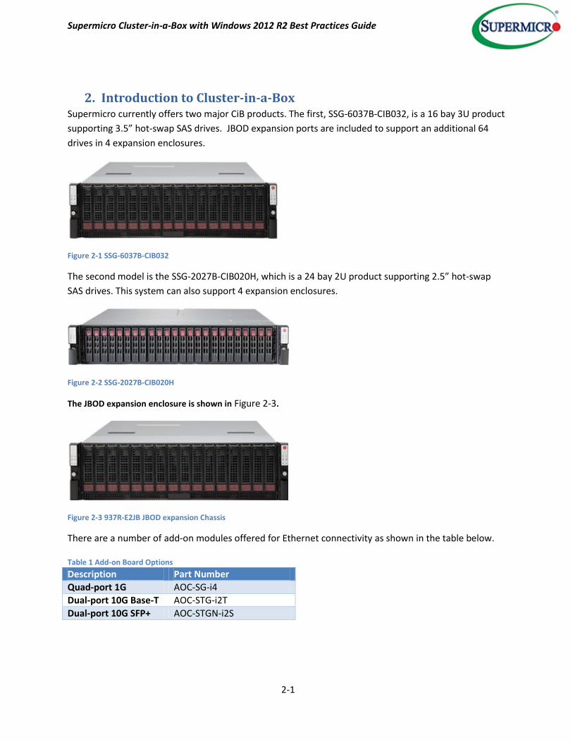
2. Introduction to Cluster-in-a-Box Supermicro currently offers two major CiB products. The first, SSG-6037B-CIB032, is a 16 bay 3U product
supporting 3.5” hot-swap SAS drives. JBOD expansion ports are included to support an additional 64
drives in 4 expansion enclosures.
Figure 2-1 SSG-6037B-CIB032
The second model is the SSG-2027B-CIB020H, which is a 24 bay 2U product supporting 2.5” hot-swap
SAS drives. This system can also support 4 expansion enclosures.
Figure 2-2 SSG-2027B-CIB020H
The JBOD expansion enclosure is shown in Figure 2-3.
Figure 2-3 937R-E2JB JBOD expansion Chassis
There are a number of add-on modules offered for Ethernet connectivity as shown in the table below. Table 1 Add-on Board Options
Description Part Number
Quad-port 1G AOC-SG-i4
Dual-port 10G Base-T AOC-STG-i2T
Dual-port 10G SFP+ AOC-STGN-i2S

Supermicro Cluster-in-a-Box with Windows 2012 R2 Best Practices Guide
2-2
Table 2 CiB Specifications at a Glance
Part Number / Datasheet SSG-6037B-CIB032 SSG-2027B-CIB020H
Form Factor 3U / 16x 3.5" Hot-swap Bays 2U / 24x 2.5" Hot-swap Bays
Server Node 2 2
Processors per Node Dual Intel Xeon E5-2403 v2 Dual Intel Xeon E5-2403 v2
Memory per Node 32GB 64GB
Hard Drives 8x 4TB Nearline SAS Drives 20x 1TB Nearline SAS Drives
SSD - 4x 200GB SSD
JBOD Expansion Ports/per Node Dual SAS2 ports Single SAS2 port
The Super SBB design provides hot-swappable canisters for active components.
Hardware Layout
Figure 2-4 shows a rear view of both models. Node locations in this document are left-to-right when the
system is viewed from the front. Each system features a number of vacant PCI-e slots for additional
functionality.
Figure 2-4 Rear View of CiB Models
Note node names may be swapped if server modules are relocated in another slot. Cluster-N1 and
Cluster-N2 names are not bound to left or right server locations.
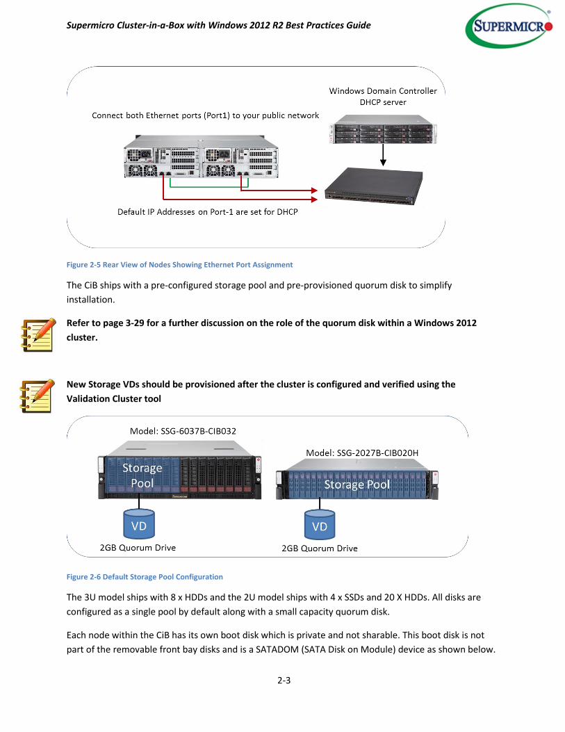
Ethernet port 1 on the nodes is set for DHCP by default and should be connected to the public network
and port 2 is set for heartbeat communications, as shown in Figure 2-5. In addition, there is an option to
add 10 Gigabit Ethernet cards, as listed in Table 1 earlier.
Supermicro Cluster-in-a-Box with Windows 2012 R2 Best Practices Guide
2-3
Figure 2-5 Rear View of Nodes Showing Ethernet Port Assignment
The CiB ships with a pre-configured storage pool and pre-provisioned quorum disk to simplify
installation.
Refer to page 3-29 for a further discussion on the role of the quorum disk within a Windows 2012
cluster.
New Storage VDs should be provisioned after the cluster is configured and verified using the
Validation Cluster tool
Figure 2-6 Default Storage Pool Configuration
The 3U model ships with 8 x HDDs and the 2U model ships with 4 x SSDs and 20 X HDDs. All disks are
configured as a single pool by default along with a small capacity quorum disk.
Each node within the CiB has its own boot disk which is private and not sharable. This boot disk is not
part of the removable front bay disks and is a SATADOM (SATA Disk on Module) device as shown below.
Supermicro Cluster-in-a-Box with Windows 2012 R2 Best Practices Guide
2-4
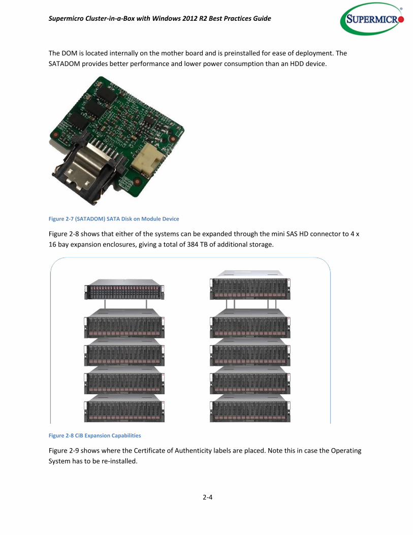
The DOM is located internally on the mother board and is preinstalled for ease of deployment. The
SATADOM provides better performance and lower power consumption than an HDD device.
Figure 2-7 (SATADOM) SATA Disk on Module Device
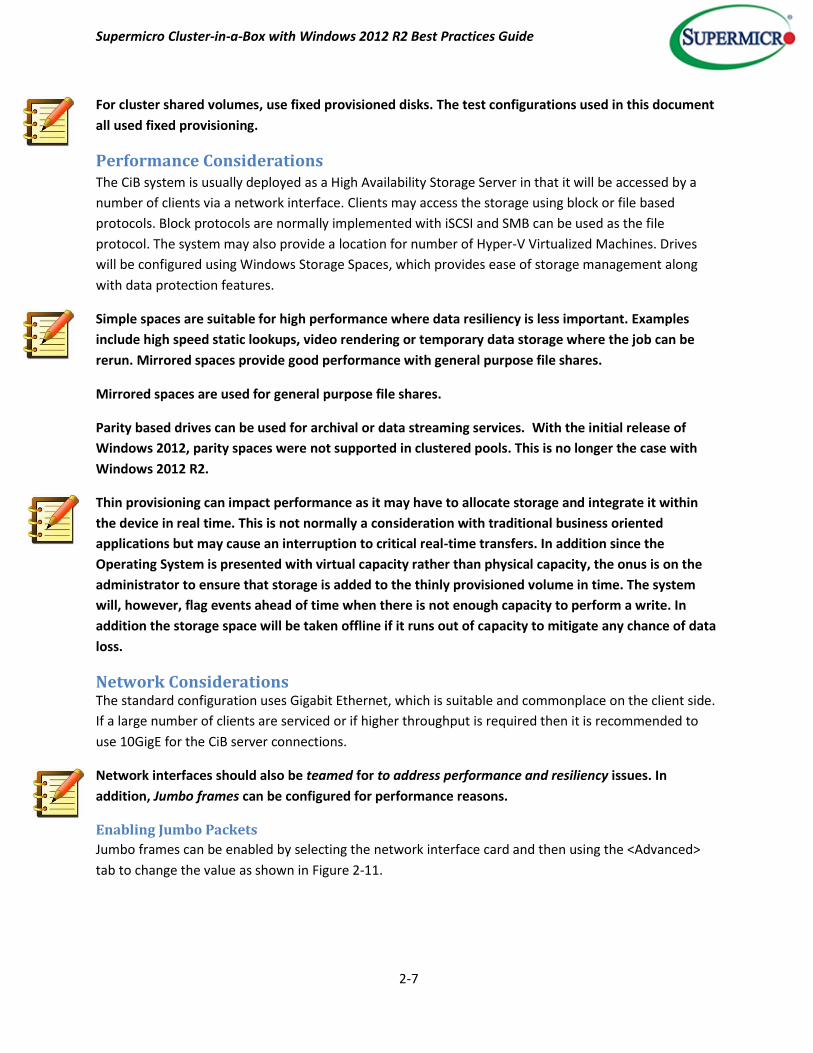
Figure 2-8 shows that either of the systems can be expanded through the mini SAS HD connector to 4 x
16 bay expansion enclosures, giving a total of 384 TB of additional storage.
Figure 2-8 CiB Expansion Capabilities
Figure 2-9 shows where the Certificate of Authenticity labels are placed. Note this in case the Operating
System has to be re-installed.

Supermicro Cluster-in-a-Box with Windows 2012 R2 Best Practices Guide
2-5
Figure 2-9 Top View Showing COA Labels
For further information refer to the references listed in this document.
Storage Spaces Storage Spaces from Microsoft virtualizes physical disks into pools which in turn can be divided into
virtual disks. These virtual disks feature improved resilience, performance and ease of management
compared to their physical counterparts and are an aggregation of the physical disks.
Layout and Resiliency Options
Storage Spaces provides a number of layout options –
Simple requires at least one disk and is optimized for performance and capacity, however it
provides no additional protection in that there is only one copy of the data.
Mirrored requires a minimum of two disks and will duplicate the data. In this case a catastrophic
disk failure will still be able to deliver the data to the clients since the remaining disk has a full
copy. In this instance only half of the physical drive capacity is available due to the mirroring
function.
Parity stripes data and redundancy information across several disks. This improves capacity
utilization when compared to the mirrored configuration described above. Single disk failure
protection can be achieved with three disks and dual disk failure protection can be achieved
with seven disks.
Storage Spaces can automatically rebuild mirror and parity spaces in which a disk fails by using
dedicated disks that are reserved for replacing failed disks (hot spares), or more rapidly by using
spare capacity on other drives in the pool. Storage Spaces also includes background scrubbing
and intelligent error correction to provide continuous service availability despite storage
component failures. In the event of a power failure or cluster failover, data integrity is preserved
so that recovery happens quickly and does not result in data loss. (Microsoft, 2014).

Supermicro Cluster-in-a-Box with Windows 2012 R2 Best Practices Guide
2-6
Performance Enhancements
Tiering
In addition to data protection, Storage Spaces also provides enhanced performance by the use of tiered
storage. When a combination of Hard Disk Drives (HDDs) and Solid State Drives (SSDs) are used
together, the system will automatically move “hot” data onto the SSDs. The improved access times of
the SSDs ensure that frequently accessed data is delivered more efficiently to the clients. This is done
transparently by the system. Tiering can be selected at virtual disk creation time and the ratio of SSD to
HDD storage space can be selected as shown in Figure 2-10. In this example the ratio is 1:10.
Figure 2-10 Tiering within a Virtual Drive
Data is dynamically moved at a sub-file level between both tiers.
Although the benefits of tiering are highly dependent on the application, in general it is well suited for
transient hot data. Hot data is also termed the working set.
The goal of tiering is that frequently accessed files are located on the SSD with less frequently
accessed files being located on the HDDs. This way the performance benefits of SSD can be realized
without suffering the cost disadvantages.
The default shipping configuration of the Supermicro SSG-2027B-CIB020H (described on page 2-1)
uses 4 x SSDs and 20 x HDDs in a single pool and with the ratio of SSD to HDD designed to ensure good
use of the tiering feature. In addition, a quorum disk is used within this shared storage pool.
Write-back Cache.
Storage Spaces can use a write-back cache on SSDs in pool-to-buffer write operations. Once the data has
been written to the SSD, an acknowledgement is sent back to the issuer of the I/O. The data is then
subsequently written to the HDD. In general this works well for small size block write operations which
are common in many applications such as transaction processing. It will also help “smooth out” short
bursts of activity.
Provisioning
Volumes may be fixed or thin provisioned. The advantage of thin provisioning is that the capacity
presented can be larger than the actual physical capacity. Storage can be added as required at a later
stage when needed rather than having to purchase it at deployment time. Thin provisioning exhibits
allocation on demand behavior.
Supermicro Cluster-in-a-Box with Windows 2012 R2 Best Practices Guide
2-7
For cluster shared volumes, use fixed provisioned disks. The test configurations used in this document
all used fixed provisioning.
Performance Considerations The CiB system is usually deployed as a High Availability Storage Server in that it will be accessed by a
number of clients via a network interface. Clients may access the storage using block or file based
protocols. Block protocols are normally implemented with iSCSI and SMB can be used as the file
protocol. The system may also provide a location for number of Hyper-V Virtualized Machines. Drives
will be configured using Windows Storage Spaces, which provides ease of storage management along
with data protection features.
Simple spaces are suitable for high performance where data resiliency is less important. Examples
include high speed static lookups, video rendering or temporary data storage where the job can be
rerun. Mirrored spaces provide good performance with general purpose file shares.
Mirrored spaces are used for general purpose file shares.
Parity based drives can be used for archival or data streaming services. With the initial release of
Windows 2012, parity spaces were not supported in clustered pools. This is no longer the case with
Windows 2012 R2.
Thin provisioning can impact performance as it may have to allocate storage and integrate it within
the device in real time. This is not normally a consideration with traditional business oriented
applications but may cause an interruption to critical real-time transfers. In addition since the
Operating System is presented with virtual capacity rather than physical capacity, the onus is on the
administrator to ensure that storage is added to the thinly provisioned volume in time. The system
will, however, flag events ahead of time when there is not enough capacity to perform a write. In
addition the storage space will be taken offline if it runs out of capacity to mitigate any chance of data
loss.
Network Considerations The standard configuration uses Gigabit Ethernet, which is suitable and commonplace on the client side.
If a large number of clients are serviced or if higher throughput is required then it is recommended to
use 10GigE for the CiB server connections.
Network interfaces should also be teamed for to address performance and resiliency issues. In
addition, Jumbo frames can be configured for performance reasons.
Enabling Jumbo Packets
Jumbo frames can be enabled by selecting the network interface card and then using the <Advanced>
tab to change the value as shown in Figure 2-11.

Supermicro Cluster-in-a-Box with Windows 2012 R2 Best Practices Guide
2-8
Figure 2-11 Enabling Jumbo Frames on an Ethernet X540-AT2 NIC
Creating a Teamed Network
To create a teamed network, select a server from the server manager screen and then right click to
select <Configure NIC teaming> to form a combined network team.
Figure 2-12 Configuring a New Teamed NIC
At the next screen select <Add to New Team>.
Supermicro Cluster-in-a-Box with Windows 2012 R2 Best Practices Guide
2-9
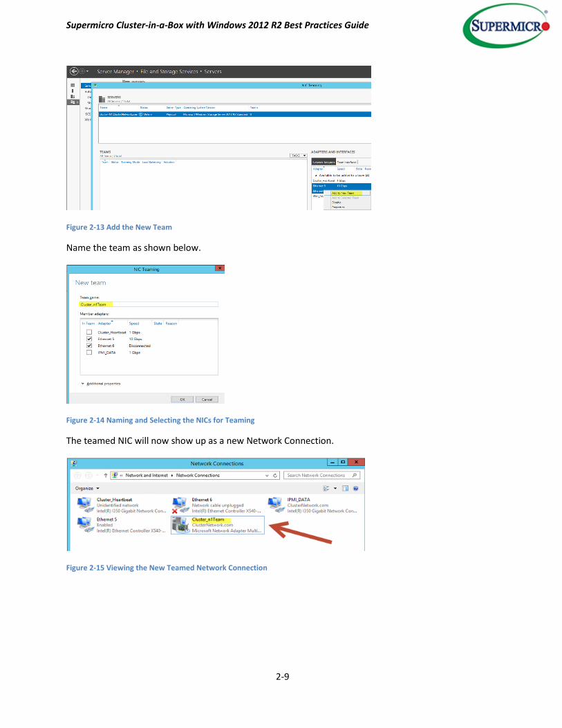
Figure 2-13 Add the New Team
Name the team as shown below.
Figure 2-14 Naming and Selecting the NICs for Teaming
The teamed NIC will now show up as a new Network Connection.
Figure 2-15 Viewing the New Teamed Network Connection

Supermicro Cluster-in-a-Box with Windows 2012 R2 Best Practices Guide
3-1
3. Configuration Walkthroughs
Example 1 - Creating a Storage Pool
From the Server Manager screen – select <Tools> - <Failover Cluster Manager>. Expand the Storage
branch on the left and select <New Storage Pool> as shown to bring up the Storage Pool Wizard.
Figure 3-1 Starting the Storage Pool Wizard
In this example, three drives have been added to the optional JBOD enclosure. Microsoft uses the term
primordial for a set of disks that have not yet been configured as a storage pool. Next the pool needs to
be named.
Supermicro Cluster-in-a-Box with Windows 2012 R2 Best Practices Guide
3-2
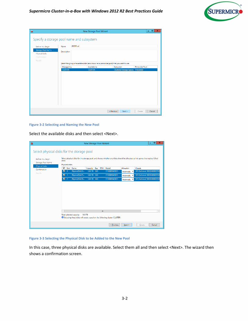
Figure 3-2 Selecting and Naming the New Pool
Select the available disks and then select <Next>.
Figure 3-3 Selecting the Physical Disk to be Added to the New Pool
In this case, three physical disks are available. Select them all and then select <Next>. The wizard then
shows a confirmation screen.
Supermicro Cluster-in-a-Box with Windows 2012 R2 Best Practices Guide
3-3
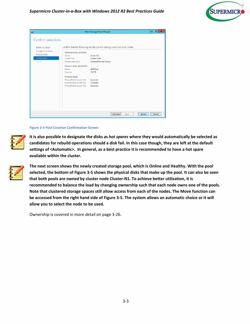
Figure 3-4 Pool Creation Confirmation Screen
It is also possible to designate the disks as hot spares where they would automatically be selected as
candidates for rebuild operations should a disk fail. In this case though, they are left at the default
settings of <Automatic>. In general, as a best practice it is recommended to have a hot spare
available within the cluster.
The next screen shows the newly created storage pool, which is Online and Healthy. With the pool
selected, the bottom of Figure 3-5 shows the physical disks that make up the pool. It can also be seen
that both pools are owned by cluster node Cluster-N1. To achieve better utilization, it is
recommended to balance the load by changing ownership such that each node owns one of the pools.
Note that clustered storage spaces still allow access from each of the nodes. The Move function can
be accessed from the right hand side of Figure 3-5. The system allows an automatic choice or it will
allow you to select the node to be used.
Ownership is covered in more detail on page 3-26.

Supermicro Cluster-in-a-Box with Windows 2012 R2 Best Practices Guide
3-4
Figure 3-5 Newly Created Storage Pool
After the pool has been created there is a prompt to configure a new virtual disk.
Example 2 - Creating a Virtual Disk
The CiB as delivered comes with a pre-configured storage pool. The virtual disk will be created from the
newly added pool.
Either accept the offer to create the new virtual disk from the storage pool wizard or, from the server
manager screen with <Storage Pool> selected, right click to start the New Virtual Disk Wizard.
Select the pool (JBODPool) to start the virtual disk creation.
Supermicro Cluster-in-a-Box with Windows 2012 R2 Best Practices Guide
3-5
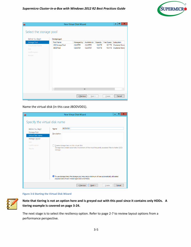
Name the virtual disk (in this case JBODVD01).
Figure 3-6 Starting the Virtual Disk Wizard
Note that tiering is not an option here and is greyed out with this pool since it contains only HDDs. A
tiering example is covered on page 3-24.
The next stage is to select the resiliency option. Refer to page 2-7 to review layout options from a
performance perspective.

Supermicro Cluster-in-a-Box with Windows 2012 R2 Best Practices Guide
3-6
Figure 3-7 Selecting the Virtual Disk Layout
In this example <Mirror> has been selected as the layout.
Note that the three physical disks used here are enough for single parity protection; however seven
drives are necessary for dual disk protection. In the interests of performance it is recommended to
have a minimum of five drives for single parity based layout schemes.
After the layout has been selected, the next choice is to decide what capacity of the pool should be
configured for the virtual drive.
Supermicro Cluster-in-a-Box with Windows 2012 R2 Best Practices Guide
3-7
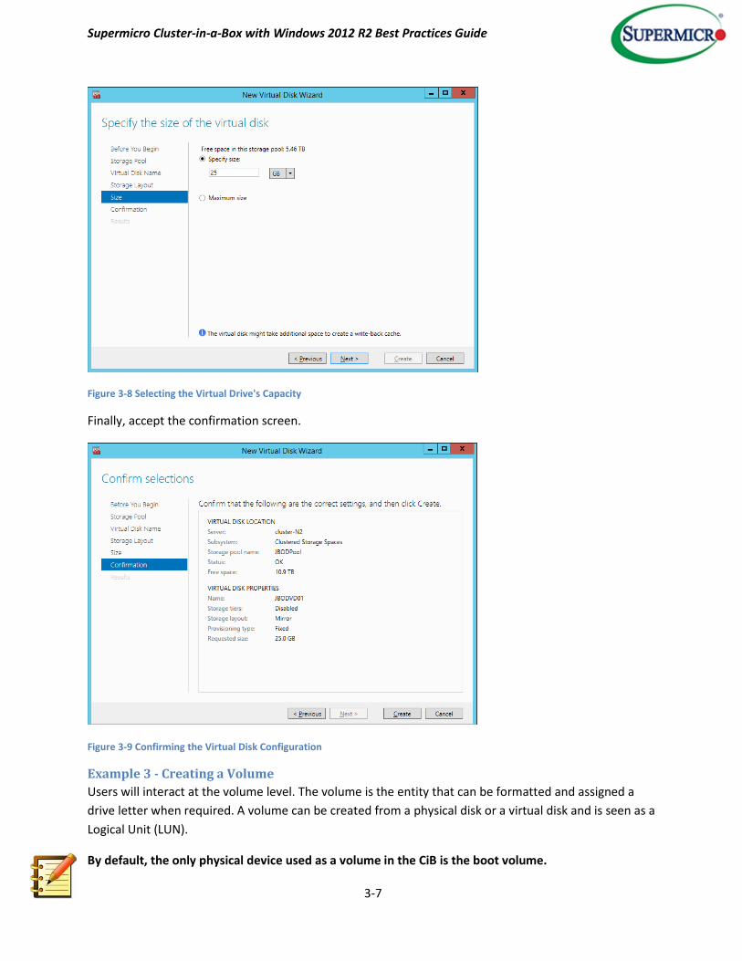
Figure 3-8 Selecting the Virtual Drive's Capacity
Finally, accept the confirmation screen.
Figure 3-9 Confirming the Virtual Disk Configuration
Example 3 - Creating a Volume
Users will interact at the volume level. The volume is the entity that can be formatted and assigned a
drive letter when required. A volume can be created from a physical disk or a virtual disk and is seen as a
Logical Unit (LUN).
By default, the only physical device used as a volume in the CiB is the boot volume.
Supermicro Cluster-in-a-Box with Windows 2012 R2 Best Practices Guide
3-8
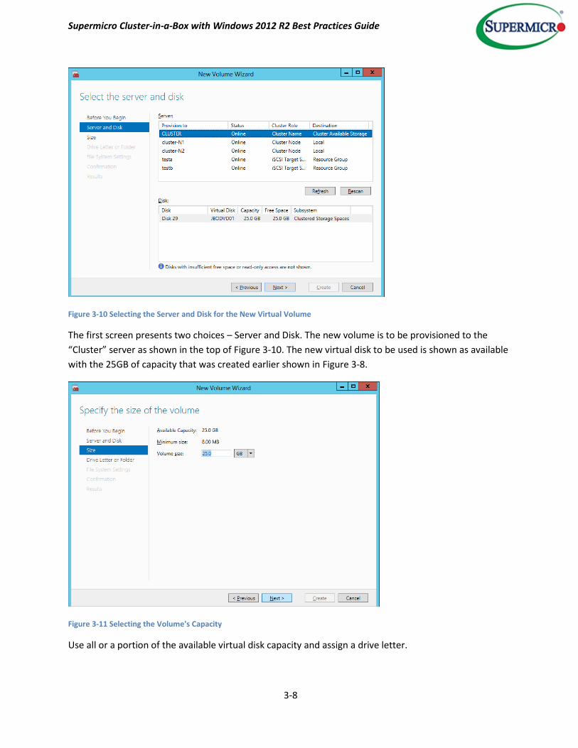
Figure 3-10 Selecting the Server and Disk for the New Virtual Volume
The first screen presents two choices – Server and Disk. The new volume is to be provisioned to the
“Cluster” server as shown in the top of Figure 3-10. The new virtual disk to be used is shown as available
with the 25GB of capacity that was created earlier shown in Figure 3-8.
Figure 3-11 Selecting the Volume's Capacity
Use all or a portion of the available virtual disk capacity and assign a drive letter.

Supermicro Cluster-in-a-Box with Windows 2012 R2 Best Practices Guide
3-9
Figure 3-12 Assigning a Volume's Drive Letter
The next stage is to decide on the file system type.
Note: NTFS is shown here as the default file system; however Microsoft has recently introduced the
ReFS (Resilient File System), which uses a checksum to provide enhanced data integrity. In addition, it
will not overwrite a previous edition of a file until the new version has been safely written to disk.
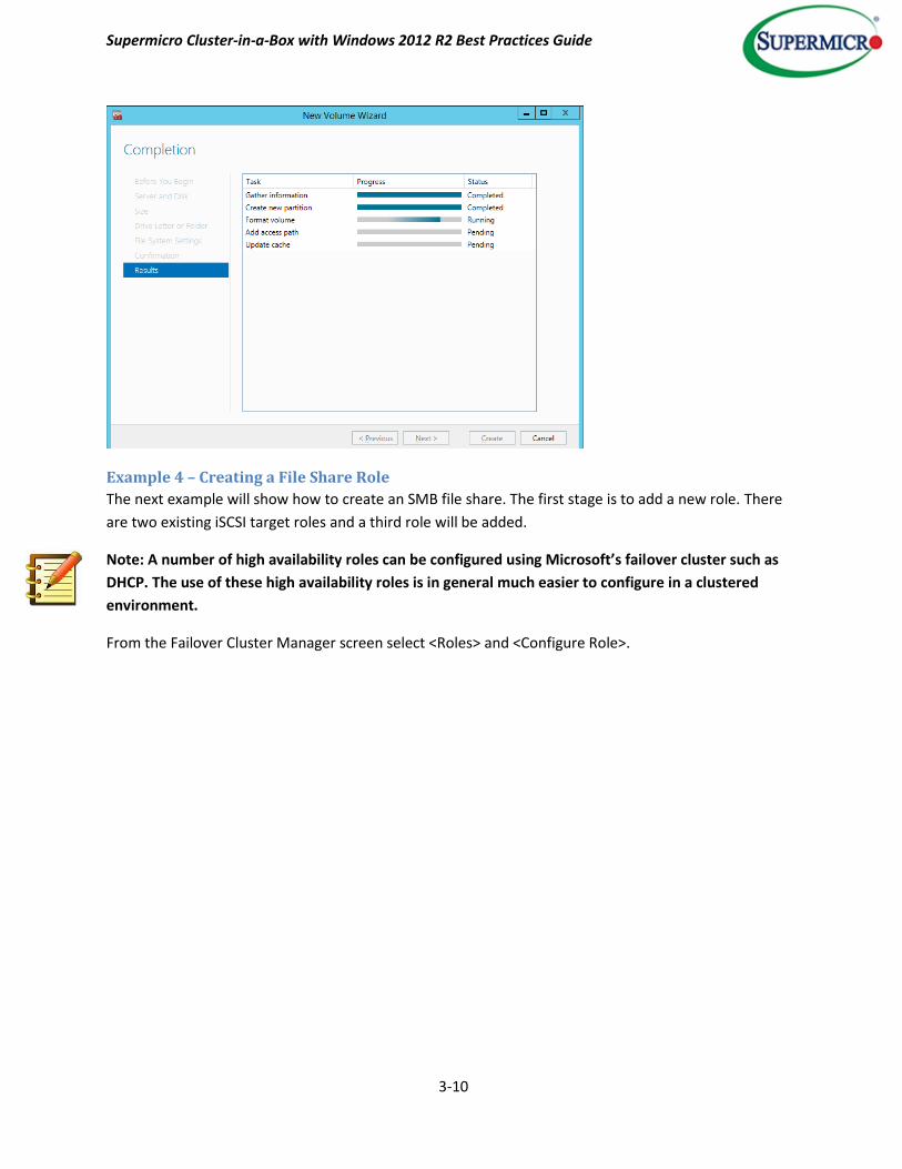
Finally, confirm the choices.
Figure 3-13 Confirmation of Volume Creation
Supermicro Cluster-in-a-Box with Windows 2012 R2 Best Practices Guide
3-10
Example 4 – Creating a File Share Role
The next example will show how to create an SMB file share. The first stage is to add a new role. There
are two existing iSCSI target roles and a third role will be added.
Note: A number of high availability roles can be configured using Microsoft’s failover cluster such as
DHCP. The use of these high availability roles is in general much easier to configure in a clustered
environment.
From the Failover Cluster Manager screen select <Roles> and <Configure Role>.

Supermicro Cluster-in-a-Box with Windows 2012 R2 Best Practices Guide
3-11
Figure 3-14 Configuring a High Availability Role
Select the desired role (in this case File Server) from the drop down choices.
Figure 3-15 Selecting the High Availability Role
Choose the <File Server for general use> option.

Supermicro Cluster-in-a-Box with Windows 2012 R2 Best Practices Guide
3-12
Note that the scale out file server is used for distributed applications where clients can access files
across multiple nodes. This is only appropriate for the SMB protocol.
Figure 3-16 Selecting the File Server Type
Name the role that will be accessed by the clients. NETBIOS names will be truncated and an IP address
will be created for client access.
Figure 3-17 Naming the Role for Clients
Select the virtual disk created earlier; also note that the selection has been expanded to show the
volumes that “belong” to this virtual disk.

Supermicro Cluster-in-a-Box with Windows 2012 R2 Best Practices Guide
3-13
Figure 3-18 Selecting Storage for the Share
Finally, confirm to accept the selection.
Figure 3-19 Confirming the Clustered Role Selection
The summary screen is shown in Figure 3-20 below.

Supermicro Cluster-in-a-Box with Windows 2012 R2 Best Practices Guide
3-14
Figure 3-20 File Server Summary Screen
Returning to the main Failover Cluster Manager screen, the new role shows the following information: it
is owned by node cluster-N1, the status is running and an IP address of 192.168.4.177 has been
allocated.
Figure 3-21 Showing the Newly Added File Server Role
Supermicro Cluster-in-a-Box with Windows 2012 R2 Best Practices Guide
3-15
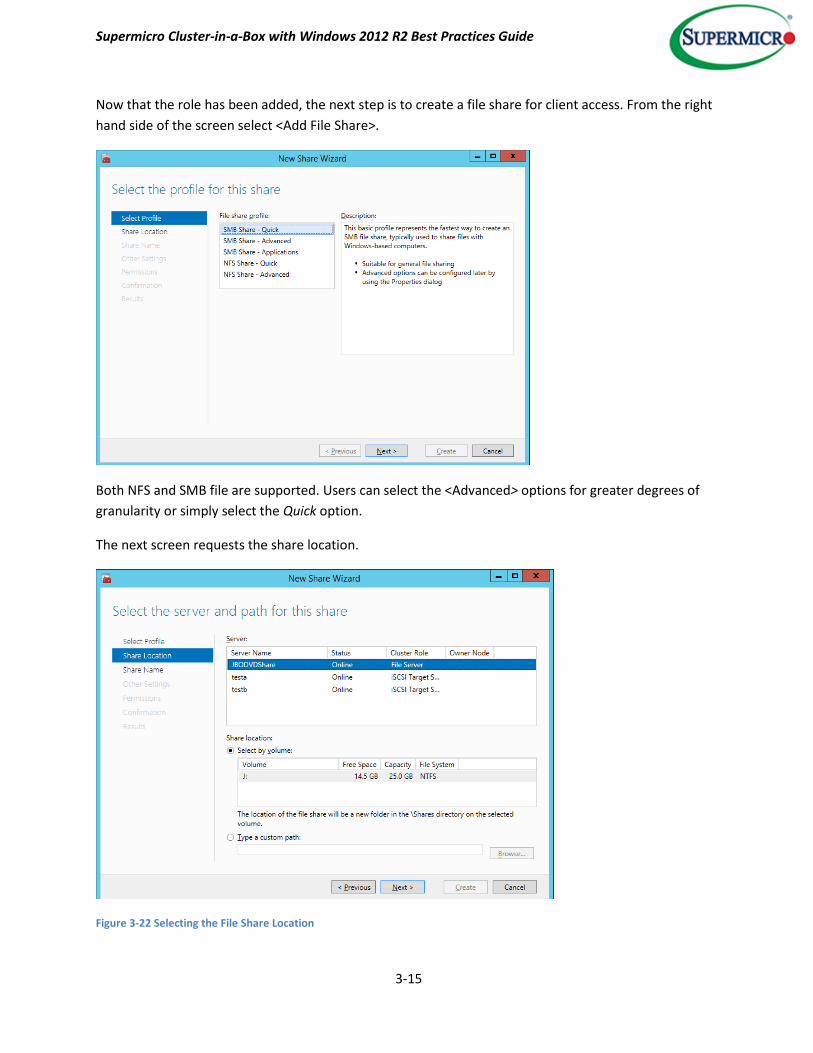
Now that the role has been added, the next step is to create a file share for client access. From the right
hand side of the screen select <Add File Share>.
Both NFS and SMB file are supported. Users can select the <Advanced> options for greater degrees of
granularity or simply select the Quick option.
The next screen requests the share location.
Figure 3-22 Selecting the File Share Location
Supermicro Cluster-in-a-Box with Windows 2012 R2 Best Practices Guide
3-16
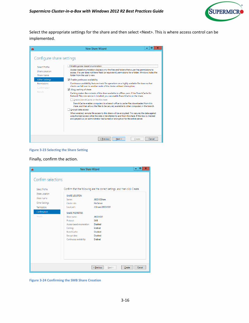
Select the appropriate settings for the share and then select <Next>. This is where access control can be
implemented.
Figure 3-23 Selecting the Share Setting
Finally, confirm the action.
Figure 3-24 Confirming the SMB Share Creation

Supermicro Cluster-in-a-Box with Windows 2012 R2 Best Practices Guide
3-17
Accessing the share
Invoke the run command <Windows key + r) and enter the IP address (as shown at the bottom of Figure
3-21) of the share into the dialog box.
Figure 3-25 Entering the File Share IP Address
The share should now appear as shown below.
Figure 3-26 Viewing the Newly Created Share
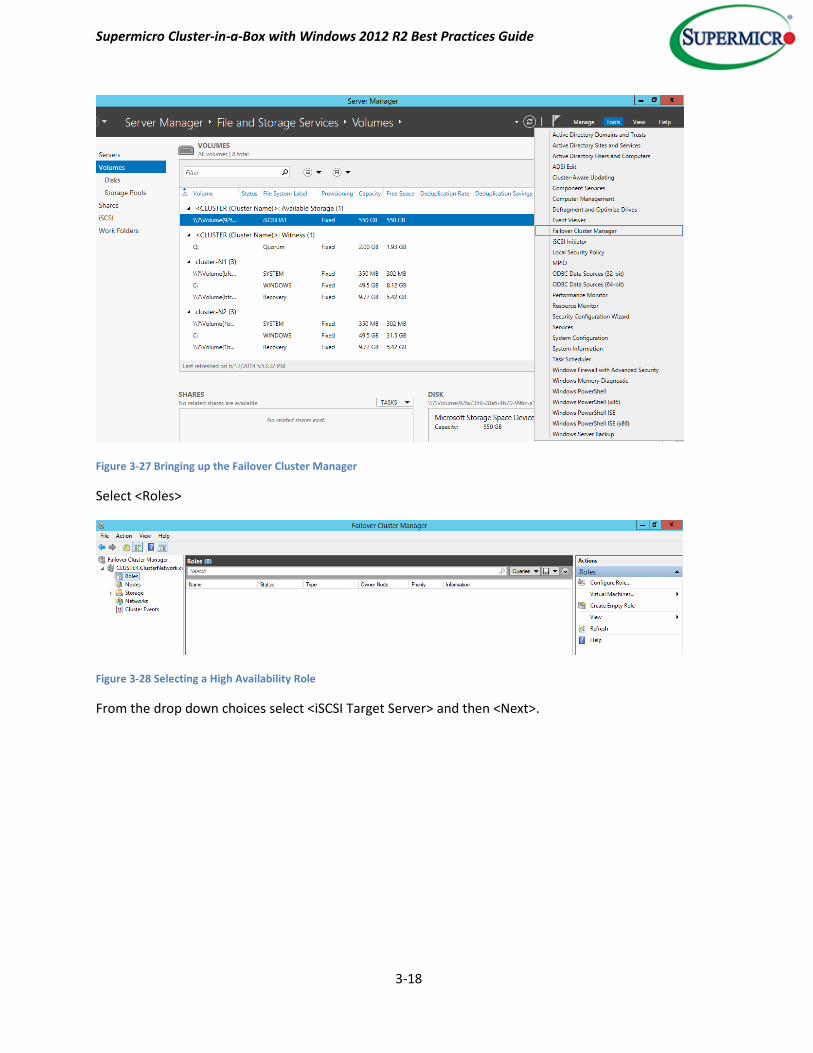
Example 5 – Creating an iSCSI Target Role
From the Server Manager main screen, select <Tools> - <Failover Cluster Manager>.
Supermicro Cluster-in-a-Box with Windows 2012 R2 Best Practices Guide
3-18
Figure 3-27 Bringing up the Failover Cluster Manager
Select <Roles>
Figure 3-28 Selecting a High Availability Role
From the drop down choices select <iSCSI Target Server> and then <Next>.

Supermicro Cluster-in-a-Box with Windows 2012 R2 Best Practices Guide
3-19
Figure 3-29 Selecting a Highly Available iSCSI Target Server Role
Name the role.
Figure 3-30 Naming the iSCSI Target Server Role
Select the virtual disk to host the iSCSI server.
Supermicro Cluster-in-a-Box with Windows 2012 R2 Best Practices Guide
3-20
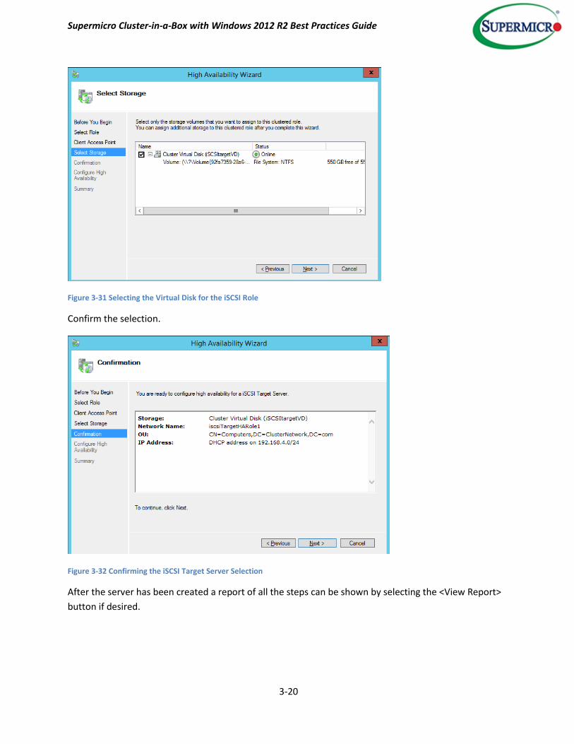
Figure 3-31 Selecting the Virtual Disk for the iSCSI Role
Confirm the selection.
Figure 3-32 Confirming the iSCSI Target Server Selection
After the server has been created a report of all the steps can be shown by selecting the <View Report>
button if desired.
Supermicro Cluster-in-a-Box with Windows 2012 R2 Best Practices Guide
3-21
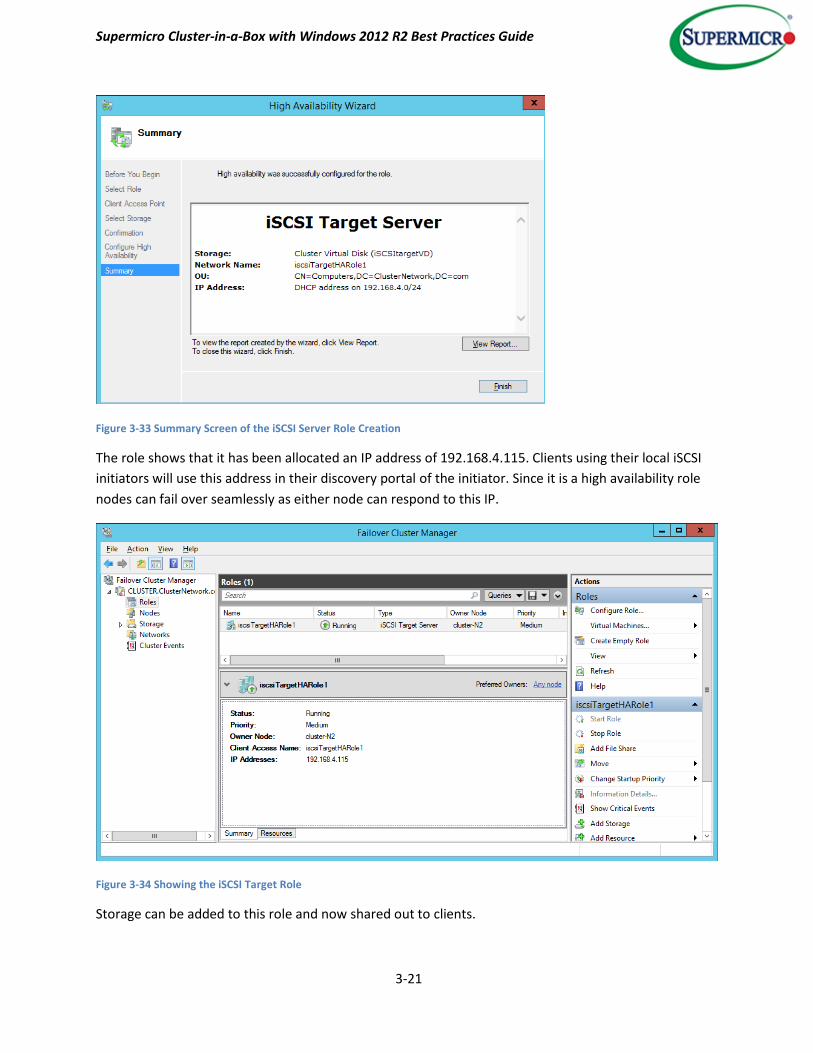
Figure 3-33 Summary Screen of the iSCSI Server Role Creation
The role shows that it has been allocated an IP address of 192.168.4.115. Clients using their local iSCSI
initiators will use this address in their discovery portal of the initiator. Since it is a high availability role
nodes can fail over seamlessly as either node can respond to this IP.
Figure 3-34 Showing the iSCSI Target Role
Storage can be added to this role and now shared out to clients.

Supermicro Cluster-in-a-Box with Windows 2012 R2 Best Practices Guide
3-22
Example 6 – Creating a Storage Tier
This example shows the creation of an iSCSI based storage tier. In Figure 3-35 below, the option to
create a storage tier is checked.
Figure 3-35 Creating a Tiered Virtual Disk
Select <Next> to configure the capacity. Since the storage tiering option was selected, the ratio of SSD
space to HDD space can be selected on a later screen. Again, this is highly dependent on the nature of
the application.
Backup or large streaming applications where the data is not regularly revisited are in general less
attractive candidates for tiering. A backup application may write the data once and then perform a
verify pass and afterwards this data might never be accessed again. A transaction oriented application
can in many cases perform well if the data is such that it is shared among many users and exhibits
locality of reference as briefly described on page 2-6.
The next stage is to configure the storage layout. In this example a mirrored layout will be selected to
provide a degree of data resiliency.

Supermicro Cluster-in-a-Box with Windows 2012 R2 Best Practices Guide
3-23
Figure 3-36 Selecting the Storage Layout
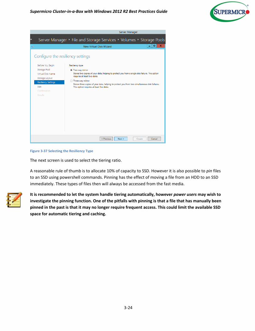
Next, configure the resiliency settings. Refer to page 2-5 for a description of resiliency options and
requirements.
A two way mirror will be used here, in that it represents a good tradeoff between performance,
capacity and cost in a file sharing application. Essentially 50% of the capacity is used for resiliency.
Three way mirroring can be used for increased data availability, and parity based spaces can be
deployed for better capacity usage.
Supermicro Cluster-in-a-Box with Windows 2012 R2 Best Practices Guide
3-24
Figure 3-37 Selecting the Resiliency Type
The next screen is used to select the tiering ratio.
A reasonable rule of thumb is to allocate 10% of capacity to SSD. However it is also possible to pin files
to an SSD using powershell commands. Pinning has the effect of moving a file from an HDD to an SSD
immediately. These types of files then will always be accessed from the fast media.
It is recommended to let the system handle tiering automatically, however power users may wish to
investigate the pinning function. One of the pitfalls with pinning is that a file that has manually been
pinned in the past is that it may no longer require frequent access. This could limit the available SSD
space for automatic tiering and caching.

Supermicro Cluster-in-a-Box with Windows 2012 R2 Best Practices Guide
3-25
Figure 3-38 Selecting the Capacity and SSD to HDD Ratio for the VD
Finally, create the virtual disk.
Figure 3-39 Virtual Disk Creation Confirmation
Supermicro Cluster-in-a-Box with Windows 2012 R2 Best Practices Guide
3-26
Example 7 – Moving Ownership
Windows 2012 R2 allows Clustered Shared Volumes (CSVs) to have simultaneous read/write access from
multiple nodes. A major benefit is that a failover can occur efficiently without the volume being
dismounted and remounted. A CSV is owned by a particular node at any one time, which coordinates
access. This ownership is balanced across the nodes automatically to ensure optimum performance.
There are times however when the administrator may want to manually change ownership. This could
be to prepare a node for maintenance, conduct tests or to do some fine tuning with regards to
throughput.
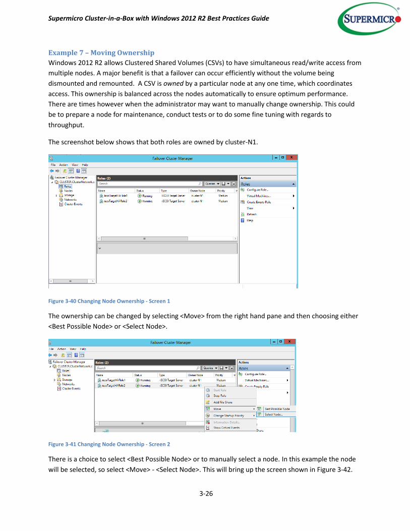
The screenshot below shows that both roles are owned by cluster-N1.
Figure 3-40 Changing Node Ownership - Screen 1
The ownership can be changed by selecting <Move> from the right hand pane and then choosing either
<Best Possible Node> or <Select Node>.
Figure 3-41 Changing Node Ownership - Screen 2
There is a choice to select <Best Possible Node> or to manually select a node. In this example the node
will be selected, so select <Move> - <Select Node>. This will bring up the screen shown in Figure 3-42.
Supermicro Cluster-in-a-Box with Windows 2012 R2 Best Practices Guide
3-27
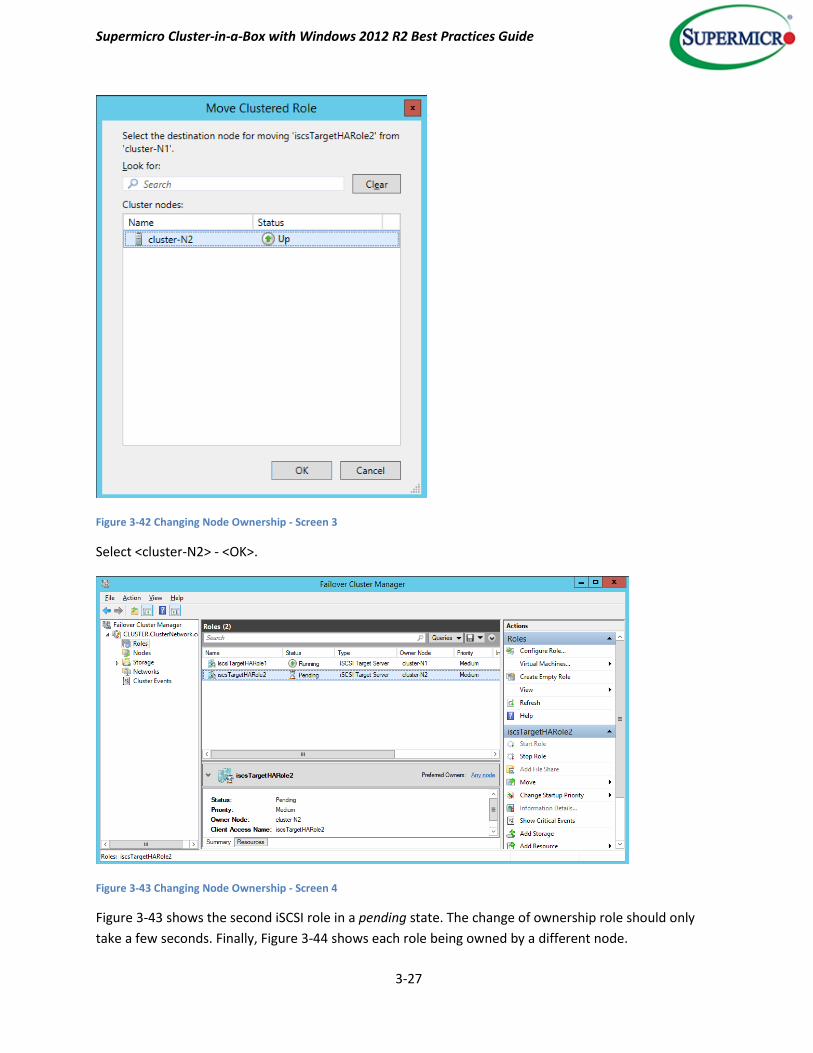
Figure 3-42 Changing Node Ownership - Screen 3
Select <cluster-N2> - <OK>.
Figure 3-43 Changing Node Ownership - Screen 4
Figure 3-43 shows the second iSCSI role in a pending state. The change of ownership role should only
take a few seconds. Finally, Figure 3-44 shows each role being owned by a different node.

Supermicro Cluster-in-a-Box with Windows 2012 R2 Best Practices Guide
3-28
Figure 3-44 Changing Node Ownership - Screen 5
To designate a particular role with a preferred node, select the role and then from the right hand screen
select <Properties> and check the preferred node.
Figure 3-45 Selecting a Role's Preferred Owner
Prior to deployment in a production role, it is recommended that freshly created resources be failed
over to each node in turn and back again to verify that both nodes can service clients in the event of a
failed node situation.

Supermicro Cluster-in-a-Box with Windows 2012 R2 Best Practices Guide
3-29
Quorum and Ownership
Ownership plays a key role in the quorum function. The idea behind quorum is to avoid uncoordinated
access to resources. In this situation each node is unaware of the other and data corruption can occur.
This is commonly known as split brain syndrome. To avoid this, the concept of quorum is introduced. In
a two node cluster such as Supermicro’s CiB product, each node is allotted a single vote and a third
resource – the quorum disk is also given a vote. For the cluster to function normally at least of two votes
must be met. If there is uncoordinated access one node will own the quorum resource and therefore
hold two votes. The other node will have no access to the quorum disk and will only hold one vote. Since
one vote is not enough to maintain a cluster, cluster services will be stopped and the node will not be
able to access the cluster resources. When the source of the issue is found the node without the
necessary number of votes will be allowed to join the cluster in a controlled, coordinated fashion.
The quorum disk must be a shared volume so that it can be accessed by either node. The CiB comes
with a pre-configured quorum disk within a pool. Refer to Figure 2-6 to show the disk configuration as
shipped with the CiB. (Microsoft, 2013).
Further Resources Please refer to the references for further information relating to the CiB and Windows Server 2012 R2.
Supermicro Cluster-in-a-Box with Windows 2012 R2 Best Practices Guide
4-1
4. References and Glossary
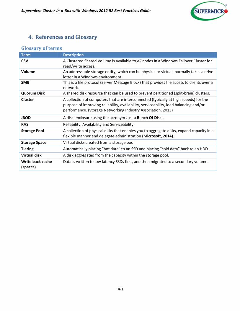
Glossary of terms Term Description
CSV A Clustered Shared Volume is available to all nodes in a Windows Failover Cluster for read/write access.
Volume An addressable storage entity, which can be physical or virtual, normally takes a drive letter in a Windows environment.
SMB This is a file protocol (Server Message Block) that provides file access to clients over a network.
Quorum Disk A shared disk resource that can be used to prevent partitioned (split-brain) clusters.
Cluster A collection of computers that are interconnected (typically at high speeds) for the purpose of improving reliability, availability, serviceability, load balancing and/or performance. (Storage Networking Industry Association, 2013)
JBOD A disk enclosure using the acronym Just a Bunch Of Disks.
RAS Reliability, Availability and Serviceability.
Storage Pool A collection of physical disks that enables you to aggregate disks, expand capacity in a flexible manner and delegate administration (Microsoft, 2014).
Storage Space Virtual disks created from a storage pool.
Tiering Automatically placing “hot data” to an SSD and placing “cold data” back to an HDD.
Virtual disk A disk aggregated from the capacity within the storage pool.
Write back cache (spaces)
Data is written to low latency SSDs first, and then migrated to a secondary volume.

Supermicro Cluster-in-a-Box with Windows 2012 R2 Best Practices Guide
4-2
References/Useful Links Microsoft. (2013, October). Deploy a Hyper-V Cluster. Retrieved from http://technet.microsoft.com/en-
us/library/jj863389.aspx
Microsoft. (2014). Failover Cluster Step-by-Step Guide: Configuring the Quorum in a Failover Cluster. Retrieved
from http://technet.microsoft.com/en-us/library/cc770620(v=WS.10).aspx
Microsoft. (2014, April). Windows Server. Retrieved from Storage Spaces overview:
http://technet.microsoft.com/en-us/library/hh831739.aspx
Storage Networking Industry Association,. (2013). SNIA Dictionary. In SNIA Dictionary (p. 40).
Supermicro. (2014). CiB Solution Customer Walkthrough. Supermicro.
Supermicro. (2014). Windows Storage Server 2012 R2 on Supermicro High-Performance 2U Cluster-in-a-Box.
Retrieved from http://www.supermicro.com/products/nfo/files/CiB/SSG-2027B-CIB020H.pdf
Supermicro. (2014). Windows Storage Server 2012 R2 on Supermicro High-Performance 3U Cluster-in-a-Box.
Retrieved from http://www.supermicro.com/products/nfo/files/CiB/SSG-6037B-CIB032.pdf