Embed Size (px)
Citation preview

UNIT-3SOFTWARE
DESIGN
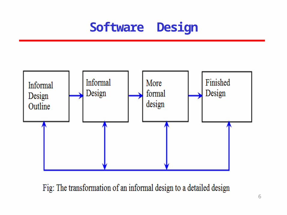
Software Design
2
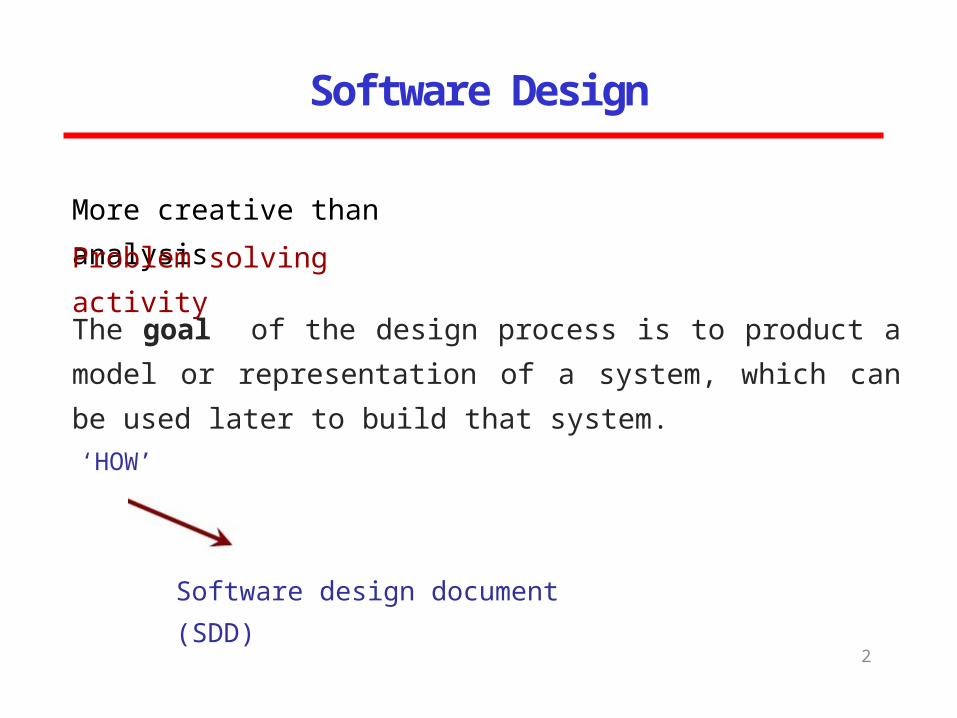
More creative than analysisProblem solving activity
‘HOW’
Software design document (SDD)
The goal of the design process is to product a model or representation of a system, which can be used later to build that system.
Why design is important?
3
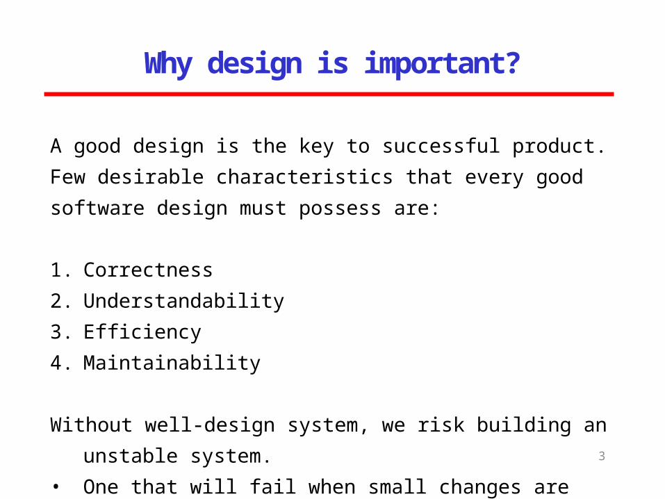
A good design is the key to successful product. Few desirable characteristics that every good software design must possess are:
1. Correctness2. Understandability3. Efficiency4. Maintainability
Without well-design system, we risk building an unstable system.
• One that will fail when small changes are made.• One that will be difficult to maintain.
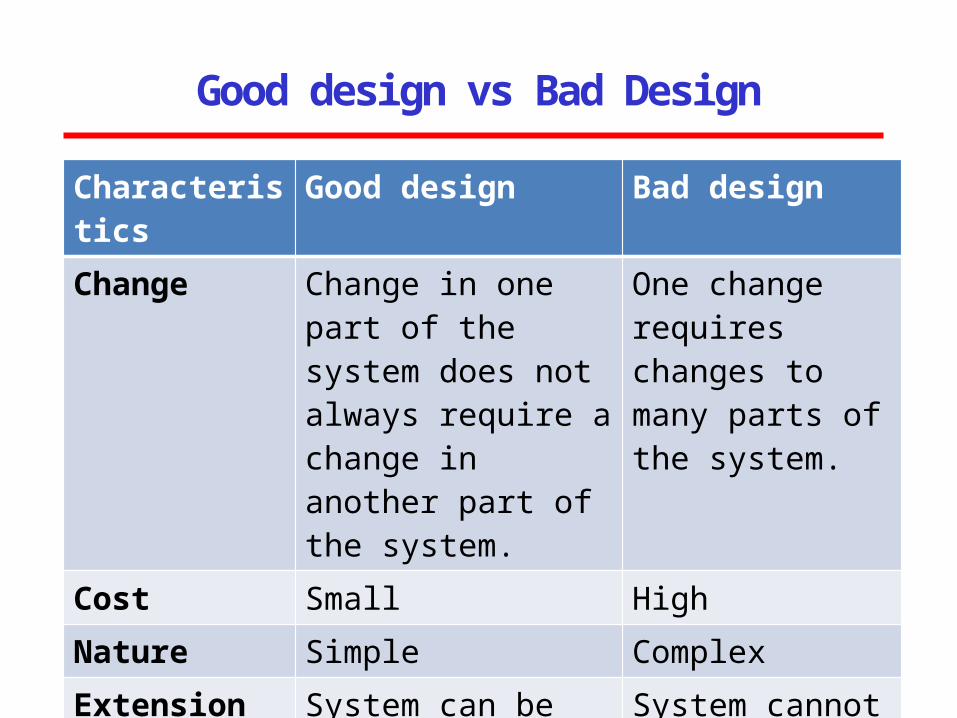
Good design vs Bad Design
4
Characteristics Good design Bad designChange Change in one part of
the system does not always require a change in another part of the system.
One change requires changes to many parts of the system.
Cost Small HighNature Simple ComplexExtension System can be
extended with changes in only one place
System cannot be extended easily.
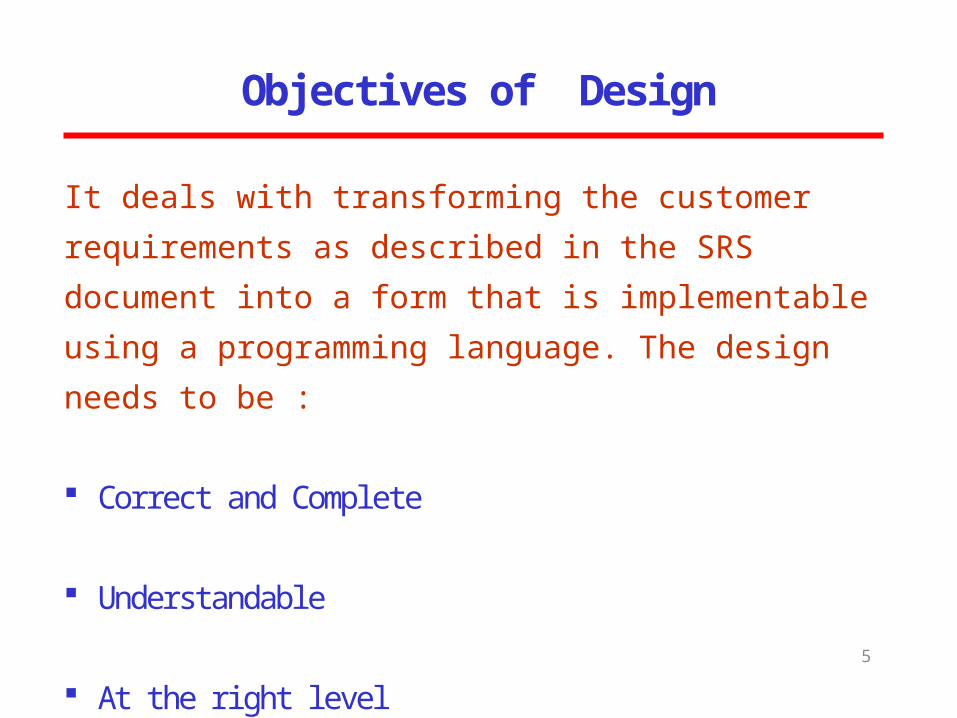
Objectives of Design
5
It deals with transforming the customer requirements as described in the SRS document into a form that is implementable using a programming language. The design needs to be :
Correct and Complete
Understandable
At the right level
Maintainable
Software Design
6
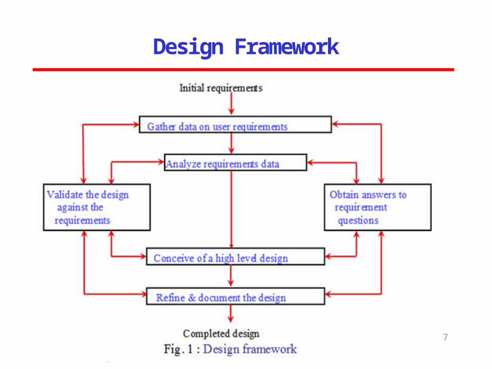
Design Framework
7
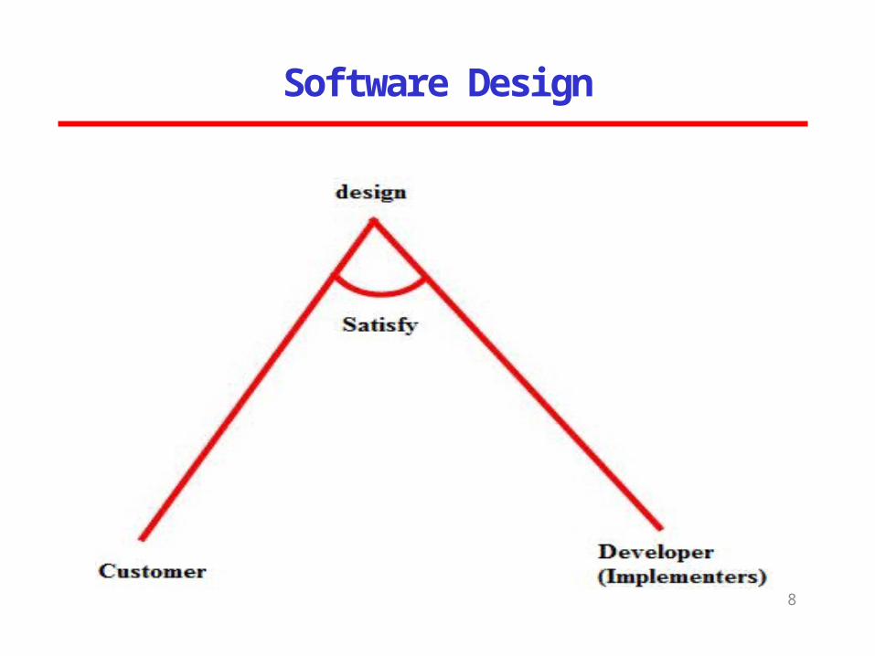
Software Design
8
Software Design
9
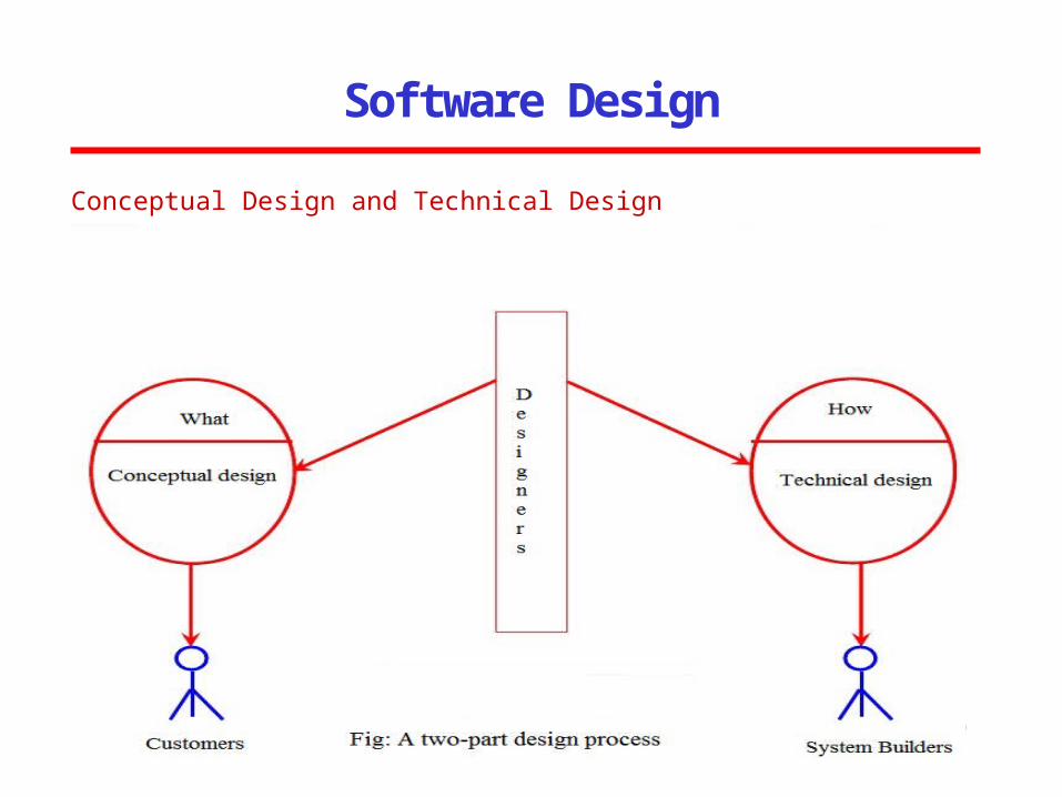
Conceptual Design and Technical Design
Software Design
10
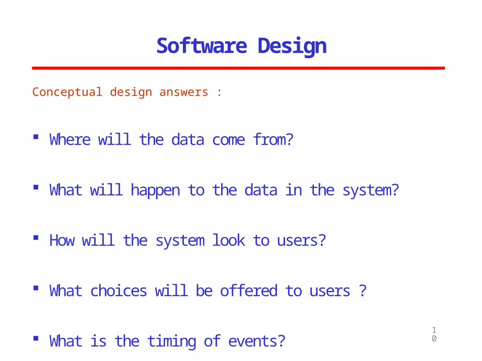
Conceptual design answers :
Where will the data come from?
What will happen to the data in the system?
How will the system look to users?
What choices will be offered to users ?
What is the timing of events?
How will the reports and screens look like?
Software Design
11
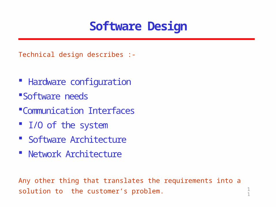
Technical design describes :-
Hardware configurationSoftware needsCommunication Interfaces I/O of the system Software Architecture Network Architecture
Any other thing that translates the requirements into a solution to the customer’s problem.
HLD and LLD
12
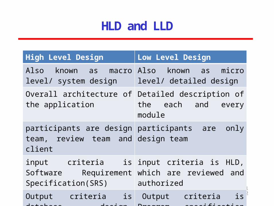
High Level Design Low Level DesignAlso known as macro level/ system design
Also known as micro level/ detailed design
Overall architecture of the application
Detailed description of the each and every module
participants are design team, review team and client
participants are only design team
input criteria is Software Requirement Specification(SRS)
input criteria is HLD, which are reviewed and authorized
Output criteria is database design, functional design and review record
Output criteria is Program specification and unit test plan
LOW LEVEL DESIGN
13
MODULARIZATION
A system is considered modular, if it consists of discrete components so that each component can be implemented separately and a change to one component has minimal impact on other components.
Advantages of Modular Systems
14
• Modular systems are easier to understand and explain because their parts are functionally independent.
• Modular systems are easier to document because each part can be documented as an independent unit.
• Programming individual modules is easier because the programmer can focus on just one small, simple problem rather than a large complex problem.
• Testing and debugging individual modules is easier because they can be dealt with in isolation from the rest of the program.
• Bugs are easier to isolate and understand and they can be fixed without fear of introducing problems outside the module.
DESIGN MODEL
15
After analyzing and specifying all the requirements, the process of software design begins. Each of the elements of analysis model is used to create the design model. The elements of design model are:-
1. Data Design (ER Diagram + Data Dictionary)
2. Architectural Design (DFD)
3. Interface Design (DFD + Control flow diagrams)
4. Component-level Design (Process + Control specification)
SOFTWARE DESIGN
16
Software design is a creative process, just like designing anything else
To see a wrong design, we can check with the requirements in the analysis model
To see a bad design, we need to assess the design model and analyze the components, whether the performance can be improved by changing the modules or the interfaces
In analyzing the software Design, many factors are used, out of which two important factors are –
Coupling Cohesion
COUPLING
17
Coupling is the measure of “the degree of interdependence between modules".
We aim to minimize coupling – to make modules as independent as possible.
Low coupling can be achieve by:eliminating unnecessary relationshipsreducing the number of necessary relationships
COUPLING
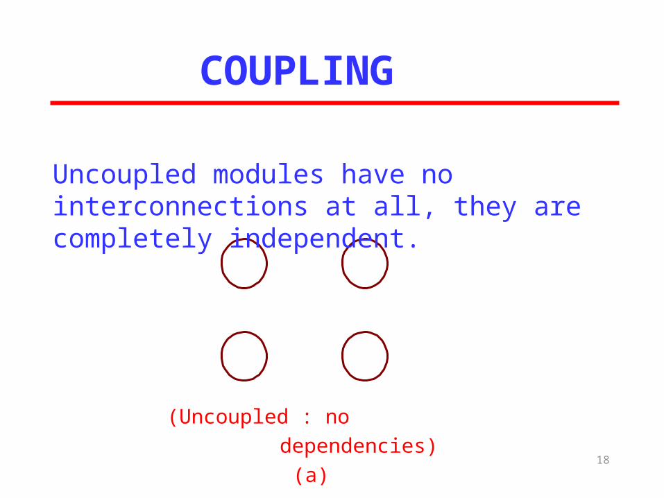
(Uncoupled : no dependencies) (a)
18
Uncoupled modules have no interconnections at all, they are completely independent.
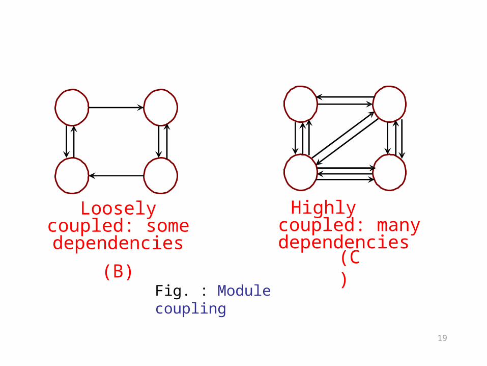
Loosely coupled: some dependencies
(B)
Highly coupled: many dependencies
(C)
Fig. : Module coupling
19
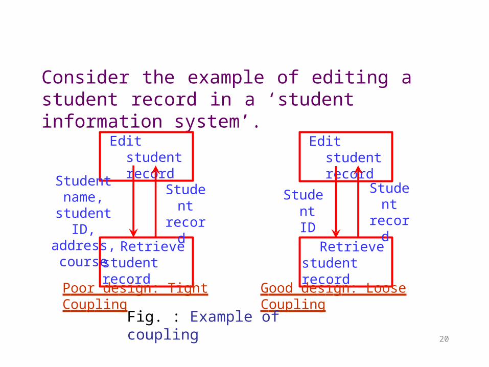
Consider the example of editing a student record in a ‘student information system’.
Edit student record
Retrieve student record
Student name, student ID, address, course
Student record
Edit student record
Retrieve student record
Student record
20
Student ID
Poor design: Tight Coupling Good design: Loose Coupling
Fig. : Example of coupling
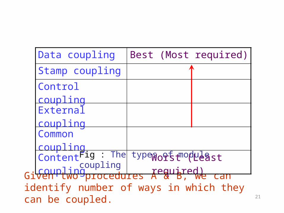
Given two procedures A & B, we can identify number of ways in which they can be coupled.
Fig : The types of module coupling
21
Data coupling Best (Most required)
Stamp coupling
Control coupling
External coupling
Common coupling
Content coupling Worst (Least required)
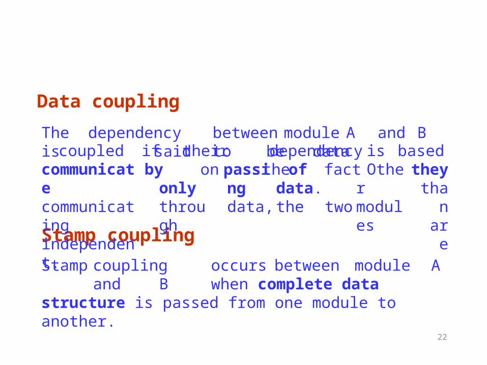
Data coupling
22
Stamp couplingStamp coupling occurs between module A and B when complete data structure is passed from one module to another.
The dependency between module A and B is said to be datacoupled if their dependency is based on the fact they
than are
communicate communicating independent.
byonly through
passing data,
of
data. thetwo
Other modules
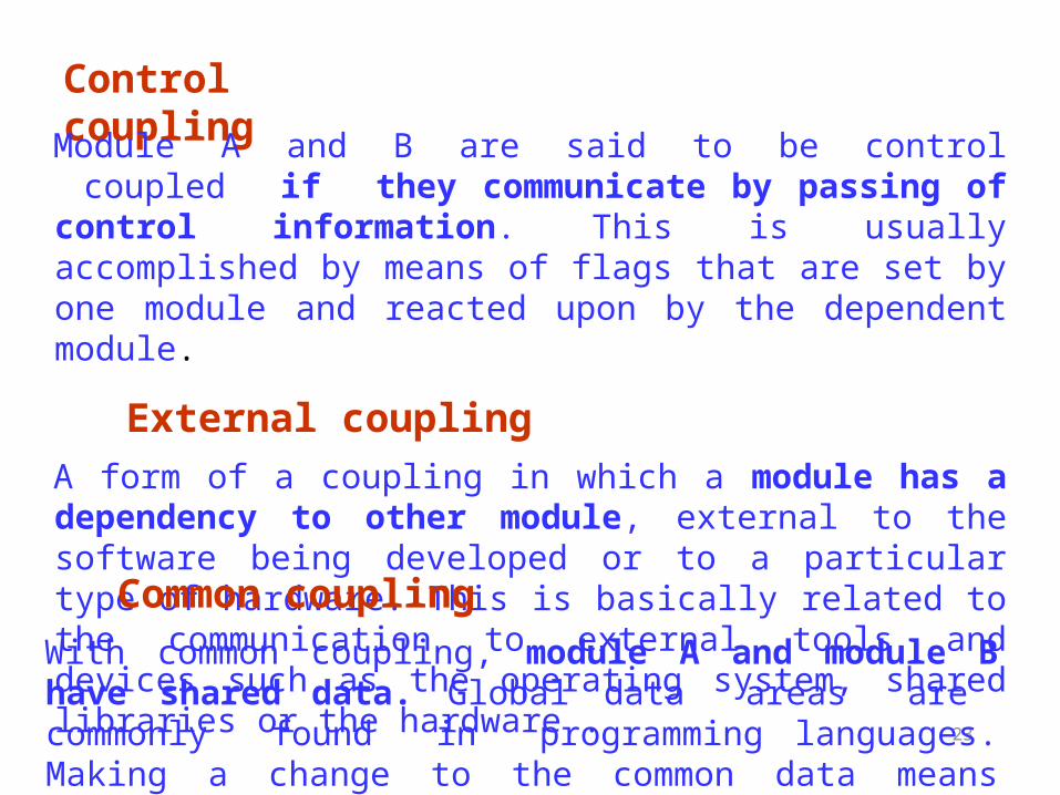
Control coupling
23
Module A and B are said to be control coupled if they communicate by passing of control information. This is usually accomplished by means of flags that are set by one module and reacted upon by the dependent module.
External couplingA form of a coupling in which a module has a dependency to other module, external to the software being developed or to a particular type of hardware. This is basically related to the communication to external tools and devices such as the operating system, shared libraries or the hardware . Common couplingWith common coupling, module A and module B have shared data. Global data areas are commonly found in programming languages. Making a change to the common data means tracing back to all the modules which access that data to evaluate the effect of changes.
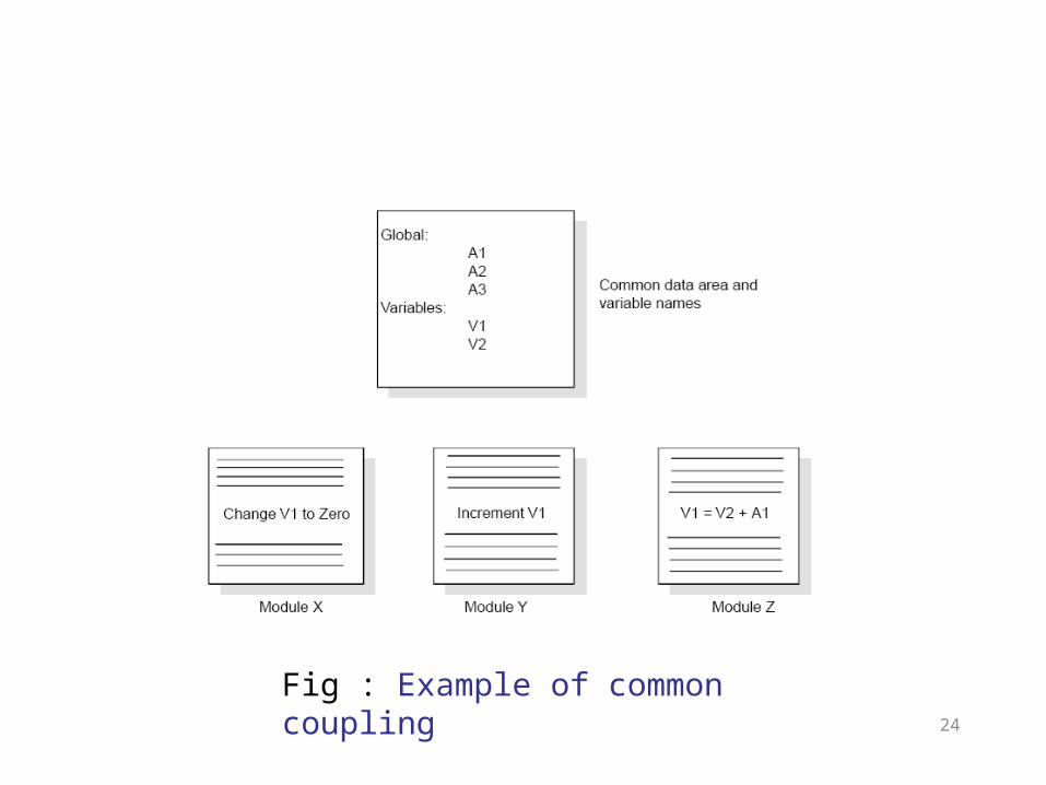
Fig : Example of common coupling24
Content coupling
25
Content coupling occurs when module A changes data of module B or when control is passed from one module to the middle of another.
Impact of Coupling on Design
26
A good design process should aim at reducing coupling.
Reduction of coupling -> reduction of dependence of onemodule on another -> increase the independence of module ->increase the ability to change or maintain the modules.
COHESION
27
Cohesion measures how a single module is related to a particular functionality in the system.
– only one module is involved – ideally, a highly cohesive module should do only one task/ activity/function – example:
• a sorting module that contains only one sorting function and this function sorts integers only. • a sorting module that contains several sorting functions that implement various sorting techniques but all sort integers only. • a sorting module that contains several sorting functions that implement various sorting techniques but sort integers and floats.
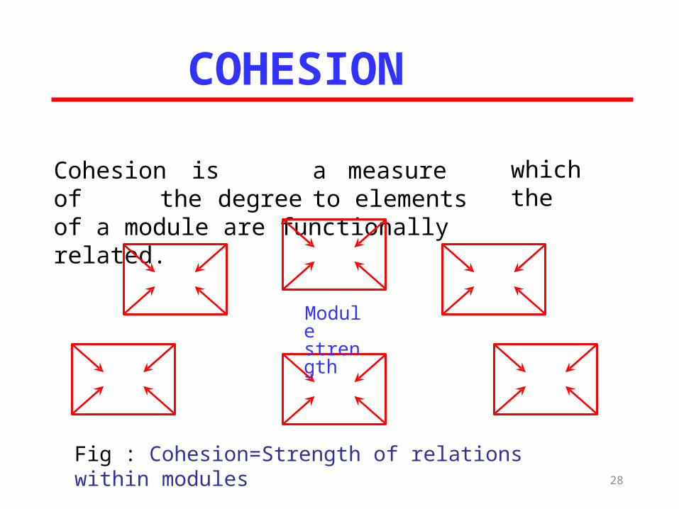
Cohesion is a measure of the degree to elements of a module are functionally related.
which the
COHESION
Fig : Cohesion=Strength of relations within modules28
Module strength
Types of cohesion
29
➢ Functional cohesion
➢ Sequential cohesion
➢ Procedural cohesion
➢ Temporal cohesion
➢ Logical cohesion
➢ Coincident cohesion
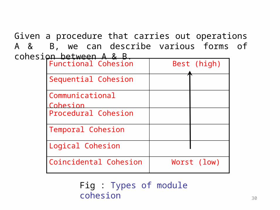
Fig : Types of module cohesion
30
Functional Cohesion Best (high)
Sequential Cohesion
Communicational Cohesion
Procedural Cohesion
Temporal Cohesion
Logical Cohesion
Coincidental Cohesion Worst (low)
Given a procedure that carries out operations A & B, we can describe various forms of cohesion between A & B.
Functional Cohesion
31
➢ . This is very good reason for them to be contained in the same procedure.
➢ All elements contribute to the execution of one and only one problem-related task
➢ Examples of functional cohesive modules:• Compute cosine of angle• Read transaction record• Assign seat to airline passenger
➢A and B are part of a single functional task
Sequential Cohesion
32
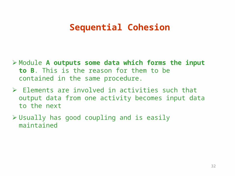
➢ Module A outputs some data which forms the input to B. This is the reason for them to be contained in the same procedure.
➢ Elements are involved in activities such that output data from one activity becomes input data to the next
➢ Usually has good coupling and is easily maintained
Communicational Cohesion
33
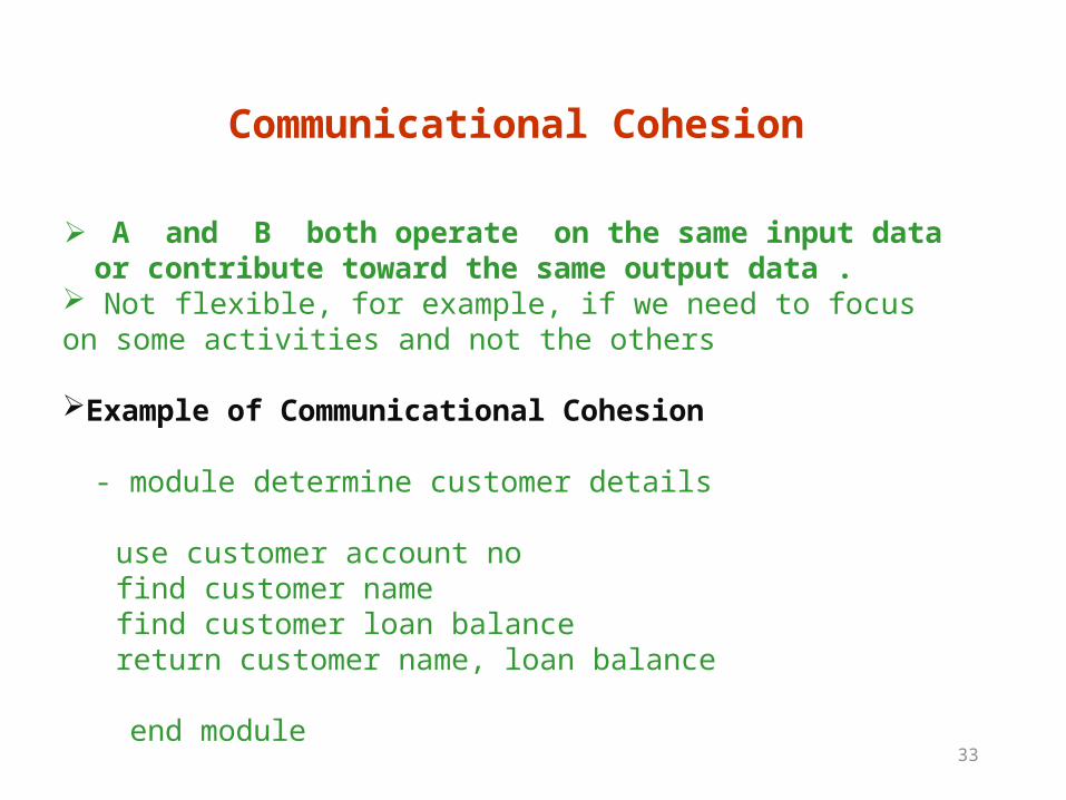
➢ A and B both operate on the same input data or contribute toward the same output data .
Not flexible, for example, if we need to focus on some activities and not the others Example of Communicational Cohesion
- module determine customer details
use customer account nofind customer namefind customer loan balancereturn customer name, loan balance
end module
34
Procedural Cohesion
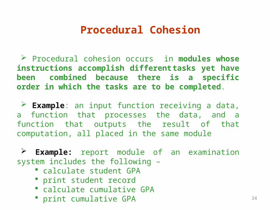
Procedural cohesion occurs in modules whose instructions accomplish different tasks yet have been
combined because there is a specific order in which the tasks are to be completed.
Example: an input function receiving a data, a function that processes the data, and a function that outputs the result of that computation, all placed in the same module
Example: report module of an examination system includes the following –
calculate student GPA print student record calculate cumulative GPA print cumulative GPA
35
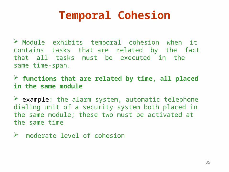
Module exhibits temporal cohesion when it contains tasks that are related by the fact that all tasks must be executed in the same time-span.
functions that are related by time, all placed in the same module
example: the alarm system, automatic telephone dialing unit of a security system both placed in the same module; these two must be activated at the same time
moderate level of cohesion
Temporal Cohesion
36
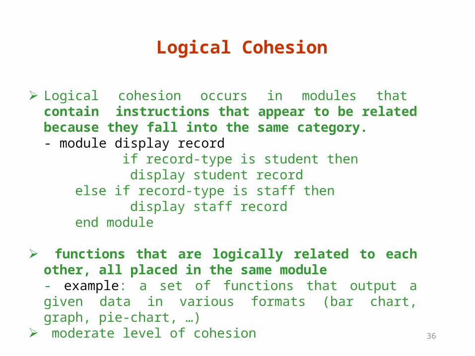
Logical Cohesion
➢ Logical cohesion occurs in modules that contain instructions that appear to be related because they fall into the same category.- module display record
if record-type is student then display student record else if record-type is staff then display staff record end module
➢ functions that are logically related to each other, all placed in the same module- example: a set of functions that output a given data in various formats (bar chart, graph, pie-chart, …)
➢ moderate level of cohesion
37
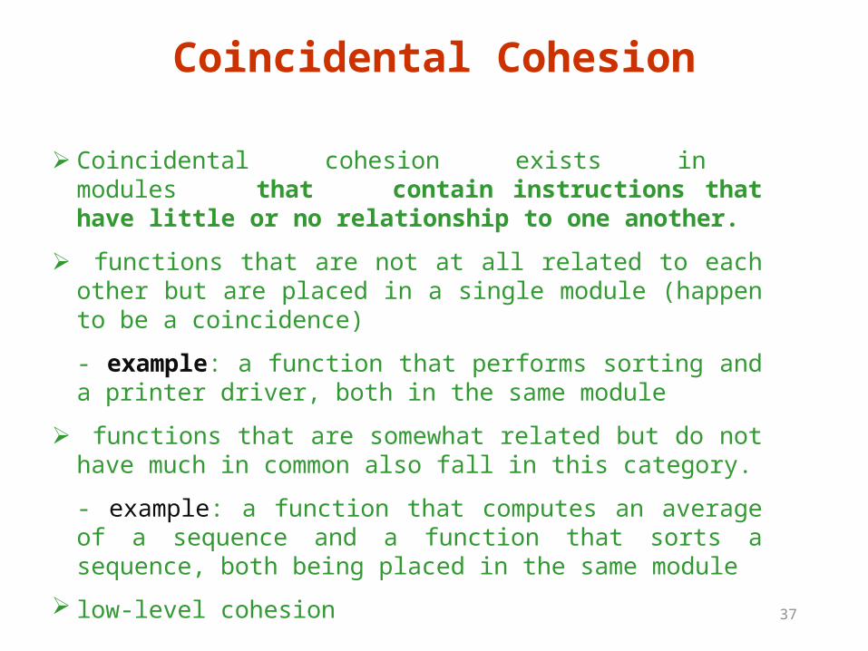
➢ Coincidental cohesion exists in modules that contain instructions that have little or no relationship to one another.
➢ functions that are not at all related to each other but are placed in a single module (happen to be a coincidence)
- example: a function that performs sorting and a printer driver, both in the same module
➢ functions that are somewhat related but do not have much in common also fall in this category.
- example: a function that computes an average of a sequence and a function that sorts a sequence, both being placed in the same module
low-level cohesion
Coincidental Cohesion
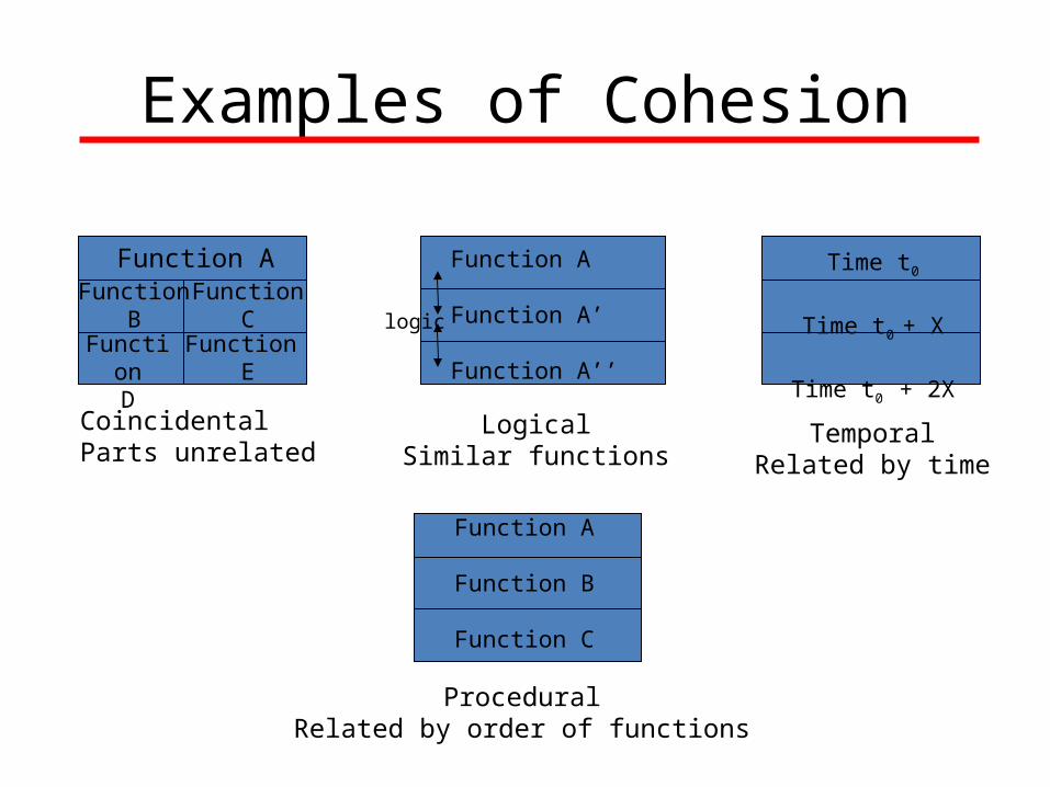
Examples of Cohesion
Function AFunction
BFunction
D
FunctionC
Function E
CoincidentalParts unrelated
Function A
Function A’
Function A’’
logic
LogicalSimilar functions
Time t0
Time t0 + X
Time t0 + 2X
TemporalRelated by time
Function A
Function B
Function C
ProceduralRelated by order of functions
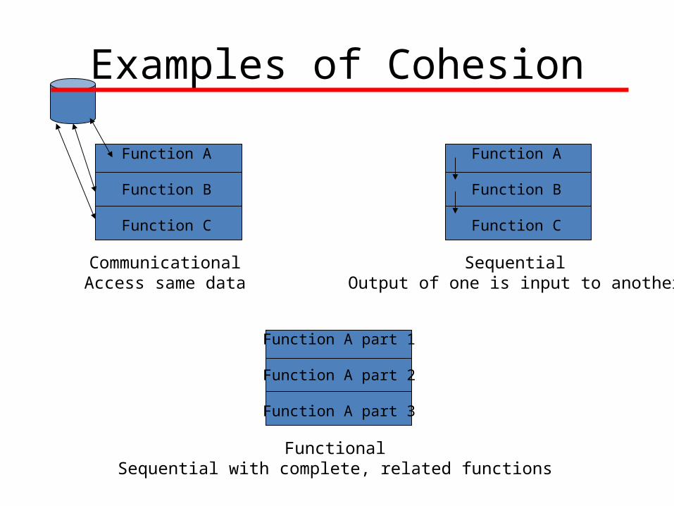
Examples of Cohesion
Function A part 1
Function A part 2
Function A part 3
FunctionalSequential with complete, related functions
Function A
Function B
Function C
CommunicationalAccess same data
Function A
Function B
Function C
SequentialOutput of one is input to another
Impact of Cohesion on Design
40
A good design process should try to maximize cohesion of each module
maximizing cohesion -> maximizing the use of the module towards particular functionality -> appropriate modularization of the design
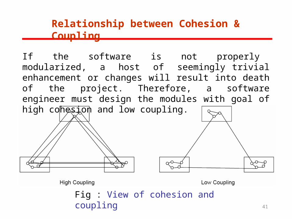
Relationship between Cohesion & Coupling
Fig : View of cohesion and coupling
If the software is not properly modularized, a host of seemingly trivial enhancement or changes will result into death of the project. Therefore, a software engineer must design the modules with goal of high cohesion and low coupling.
41
Evaluating Coupling and Cohesion
42
• Coupling can be evaluated using metrics tools. - metrics will be discussed later.
• Cohesion is generally evaluated manually by experts / software engineers. – walk through the design documents and iterate the design until cohesion is improved to a satisfactory level .
HIGH LEVEL DESIGN
43
ARCHITECTURAL DESIGN
The HLD, also called architectural design. Large systems are always decomposed into subsystems that provide some related set of services. The initial design process of identifying these sub-systems and establishing a framework for sub-system control and communication is called architectural design.
Architectural design methods look into various alternate architectural style of designing a system. These are:
• Data centric architecture• Data flow architecture• Object oriented architecture• Layered architecture
ARCHITECTURAL DESIGN
44
Data centric architecture approach involves the use of a central database operations of inserting, updating it in the form of a table.
Data flow architecture is applied when input data takes the form of output after passing through various phases of transformations. These transformations can be through various computations done on data.
In Object oriented architecture, the software design moves around the classes and objects of the system. The class encapsulates the data and methods.
Layered approach defines the number of layers and each layer performs tasks. The outermost layer handles the functionality of user interface and the innermost layer handles interaction with the hardware.
Objective of Architectural Design
45
• To develop a model of software architecture, this gives overall organization of program module in the software product.
• To control relationship between modules. One module may control another module or may be controlled by another module.
• The organization of module can be represented through a tree like structure.
•In addition, HLD possess some attributes such as height, depth, width and module fan-in, fan-out.
Attributes
46
The height or depth of the design hierarchy is the number of modules along the longest path from the top-level module down to the lowest module in the hierarchy.
The width of the design hierarchy is the largest number of modules existing at a given level of the hierarchy.
The no. of components which controls a said component is called fan-in i.e, the no of incoming edges to a component.
The no. of components that are controlled by a module is called fan-out i.e, the no of outgoing edges.
STRATEGY OF DESIGN
47
A good system design strategy is to organize the program modules in such a way that are easy to develop and latter to, change. Structured design techniques help developers to deal with the size and complexity of programs. Analysts create instructions for the developers about how code should be written and how pieces of code should fit together to form a program. It is important for two reasons:
➢ First, even pre-existing code, if any, needs to be understood, organized and pieced together.
➢ Second, it is still common for the project team to have to write some code and produce original programs that support the application logic of the system.
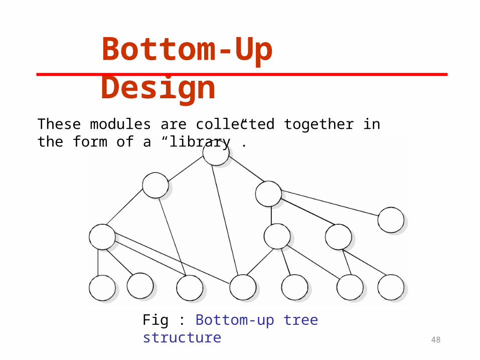
Bottom-Up Design
Fig : Bottom-up tree structure
These modules are collected together in the form of a “library”.
48
Top-Down Design
•A top down design approach starts by identifying the major modules of the system, decomposing them into their lower level modules and iterating until the desired level of detail is achieved. This is stepwise refinement; starting from an abstract design, in each step the design is refined to a more concrete level, until we reach a level where no more refinement is needed and the design can be implemented directly.
49
Hybrid Design
For top-down approach to be effective, some bottom-up approach is essential for the following reasons:
➢ To permit common sub modules.
➢ Near the bottom of the hierarchy, where the intuition is simpler, and the need for bottom-up testing is greater, because there are more number of modules at low levels than high levels.
➢ In the use of pre-written library modules, in particular, reuse of modules.
50
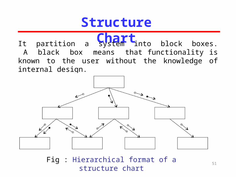
Structure ChartIt partition a system into block boxes. A black box means that functionality is known to the user without the knowledge of internal design.
Fig : Hierarchical format of a structure chart51
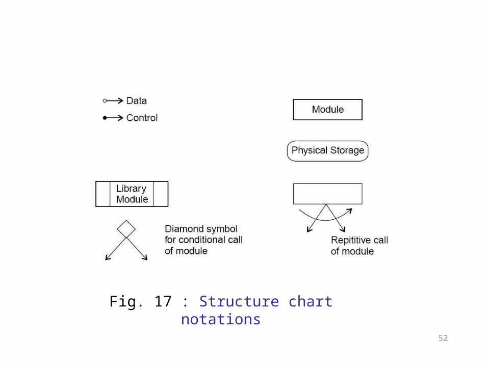
Fig. 17 : Structure chart notations
52
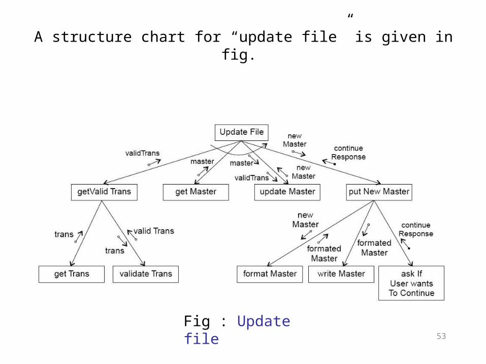
Fig : Update file
A structure chart for “update file” is given in fig.
53
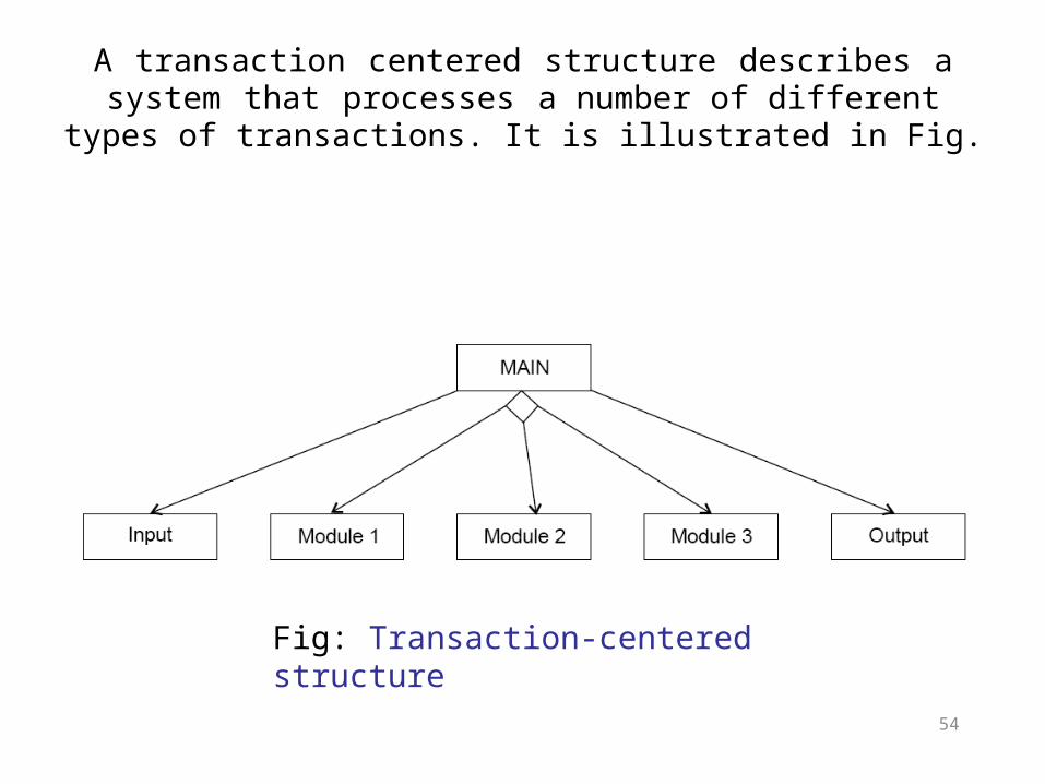
Fig: Transaction-centered structure
A transaction centered structure describes a system that processes a number of different types of transactions. It is illustrated in Fig.
54
In the above figure the MAIN module controls the system operation its functions is to:
55
➢ invoke the INPUT module to read a transaction;
➢ determine the kind of transaction and select one of a number of transaction modules to process that transaction, and
➢ output the results of the processing by callingOUTPUT module.
Pseudocode
•Pseudocode notation can be used in both the preliminary and detailed design phases.
•Using pseudocode, the designer describes system characteristics using short, concise, English language phrases that are structured by key words such as If-Then-Else, While-Do, and End.
56


![]Uptu electromechanical energy conversion](https://img.pdfslide.us/doc/110x75/58f131c01a28ab33388b456d/uptu-electromechanical-energy-conversion.jpg)